Embed Size (px)
Citation preview
Micro Motion®
Model D and DT Sensors
Instruction Manual
Installation and Operation ManualP/N 1005172, Rev. CAugust 2008

©2008, Micro Motion, Inc. All rights reserved. ELITE and ProLink are registered trademarks, and MVD and MVD Direct Connect are trademarks of Micro Motion, Inc., Boulder, Colorado. Micro Motion is a registered trade name of Micro Motion, Inc., Boulder, Colorado. The Micro Motion and Emerson logos are trademarks and service marks of Emerson Electric Co. All other trademarks are property of their respective owners.
Micro Motion® Model D and DT Sensors Instruction Manual iii
Contents
Before You Begin. . . . . . . . . . . . . . . . . . . . . . . . . . . . . . . . . . . . 1Your new sensor. . . . . . . . . . . . . . . . . . . . . . . . . . . . . . . . . . . . . 1The installation process . . . . . . . . . . . . . . . . . . . . . . . . . . . . . . . 6Additional information . . . . . . . . . . . . . . . . . . . . . . . . . . . . . . . . . 7
Step 2. Location . . . . . . . . . . . . . . . . . . . . . . . . . . . . . . . . . . . . . 9Pipe run . . . . . . . . . . . . . . . . . . . . . . . . . . . . . . . . . . . . . . . . . . . 9Maximum wiring distances . . . . . . . . . . . . . . . . . . . . . . . . . . . . . 9DT sensor junction box. . . . . . . . . . . . . . . . . . . . . . . . . . . . . . . . 10Environmental limits . . . . . . . . . . . . . . . . . . . . . . . . . . . . . . . . . . 10Valves. . . . . . . . . . . . . . . . . . . . . . . . . . . . . . . . . . . . . . . . . . . . . 10Hazardous area installations . . . . . . . . . . . . . . . . . . . . . . . . . . . 11
Step 3. Orientation . . . . . . . . . . . . . . . . . . . . . . . . . . . . . . . . 13Flow direction . . . . . . . . . . . . . . . . . . . . . . . . . . . . . . . . . . . . . . . 13Process fluid . . . . . . . . . . . . . . . . . . . . . . . . . . . . . . . . . . . . . . . . 13
Step 4. Mounting . . . . . . . . . . . . . . . . . . . . . . . . . . . . . . . . . . 17Conduit openings . . . . . . . . . . . . . . . . . . . . . . . . . . . . . . . . . . . . 18Optional Model D600 mounting . . . . . . . . . . . . . . . . . . . . . . . . . 18DT sensors . . . . . . . . . . . . . . . . . . . . . . . . . . . . . . . . . . . . . . . . . 18
Step 5. Wiring . . . . . . . . . . . . . . . . . . . . . . . . . . . . . . . . . . . . . 19Hazardous area installations . . . . . . . . . . . . . . . . . . . . . . . . . . . 19Model D sensor junction box . . . . . . . . . . . . . . . . . . . . . . . . . . . 19Model DT sensor cable and junction box . . . . . . . . . . . . . . . . . . 20Connecting and shielding 9-wire cable. . . . . . . . . . . . . . . . . . . . 21D600 sensor . . . . . . . . . . . . . . . . . . . . . . . . . . . . . . . . . . . . . . . . 24Power supply wiring to the remote booster amplifier . . . . . . . . . 26Power supply wiring to the integral booster amplifier . . . . . . . . . 27Wiring from the remote booster amplifier to the sensor . . . . . . . 28Wiring to a transmitter (D600 sensor with junction box) . . . . . . . 29Core processor to a 4-wire remote transmitter or remote host . . 32Sensor grounding . . . . . . . . . . . . . . . . . . . . . . . . . . . . . . . . . . . . 37
Step 6. Startup. . . . . . . . . . . . . . . . . . . . . . . . . . . . . . . . . . . . . 39Zeroing . . . . . . . . . . . . . . . . . . . . . . . . . . . . . . . . . . . . . . . . . . . . 39Configuration, calibration, and characterization . . . . . . . . . . . . . 39Customer Service . . . . . . . . . . . . . . . . . . . . . . . . . . . . . . . . . . . . 40
iv Micro Motion® Model D and DT Sensors Instruction Manual
Contents continued
Troubleshooting . . . . . . . . . . . . . . . . . . . . . . . . . . . . . . . . . . . 41General information. . . . . . . . . . . . . . . . . . . . . . . . . . . . . . . . . . . 41Zero drift . . . . . . . . . . . . . . . . . . . . . . . . . . . . . . . . . . . . . . . . . . . 42Erratic flow rate . . . . . . . . . . . . . . . . . . . . . . . . . . . . . . . . . . . . . . 43Inaccurate flow rate or batch total . . . . . . . . . . . . . . . . . . . . . . . . 44Inaccurate density reading . . . . . . . . . . . . . . . . . . . . . . . . . . . . . 45Inaccurate temperature reading . . . . . . . . . . . . . . . . . . . . . . . . . 46Troubleshooting at the transmitter . . . . . . . . . . . . . . . . . . . . . . . 46Troubleshooting at the sensor. . . . . . . . . . . . . . . . . . . . . . . . . . . 51
Appendix A Purge Fittings . . . . . . . . . . . . . . . . . . . . . . 55
Appendix B Rupture Disk . . . . . . . . . . . . . . . . . . . . . . . 59
Appendix C Label Maintenance and Replacement . . . . . . . . . . . . . . . . . . . . . . . . . . . . . . . . . . . 61
Appendix D Return Policy . . . . . . . . . . . . . . . . . . . . . . 65
Micro Motion® Model D and DT Sensors Instruction Manual 1
Before You Begin
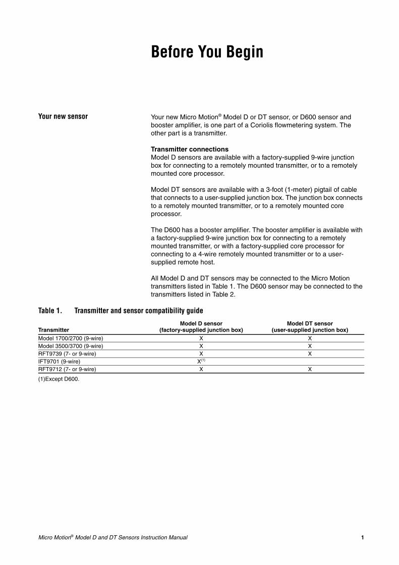
Your new sensor Your new Micro Motion® Model D or DT sensor, or D600 sensor and booster amplifier, is one part of a Coriolis flowmetering system. The other part is a transmitter.
Transmitter connectionsModel D sensors are available with a factory-supplied 9-wire junction box for connecting to a remotely mounted transmitter, or to a remotely mounted core processor.
Model DT sensors are available with a 3-foot (1-meter) pigtail of cable that connects to a user-supplied junction box. The junction box connects to a remotely mounted transmitter, or to a remotely mounted core processor.
The D600 has a booster amplifier. The booster amplifier is available with a factory-supplied 9-wire junction box for connecting to a remotely mounted transmitter, or with a factory-supplied core processor for connecting to a 4-wire remotely mounted transmitter or to a user-supplied remote host.
All Model D and DT sensors may be connected to the Micro Motion transmitters listed in Table 1. The D600 sensor may be connected to the transmitters listed in Table 2.
Table 1. Transmitter and sensor compatibility guide
TransmitterModel D sensor
(factory-supplied junction box)Model DT sensor
(user-supplied junction box)Model 1700/2700 (9-wire) X XModel 3500/3700 (9-wire) X XRFT9739 (7- or 9-wire) X XIFT9701 (9-wire) X(1)
RFT9712 (7- or 9-wire) X X
(1)Except D600.
2 Micro Motion® Model D and DT Sensors Instruction Manual
Before You Begin continued
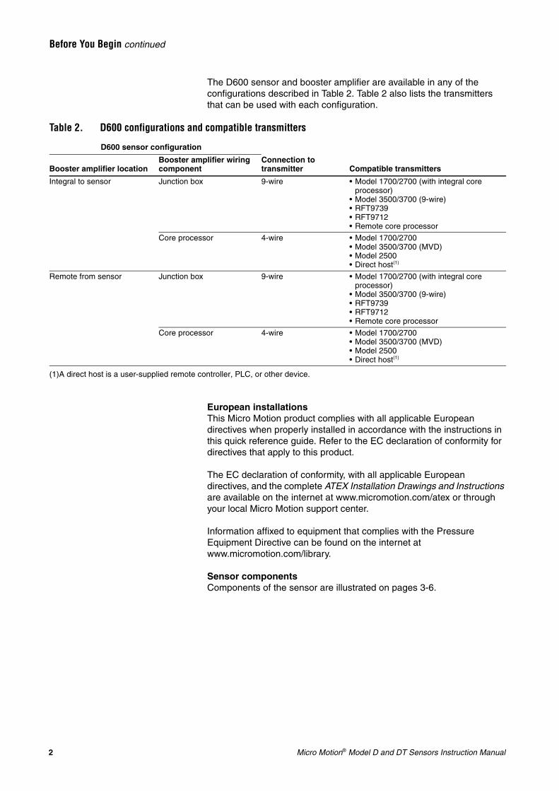
The D600 sensor and booster amplifier are available in any of the configurations described in Table 2. Table 2 also lists the transmitters that can be used with each configuration.
European installationsThis Micro Motion product complies with all applicable European directives when properly installed in accordance with the instructions in this quick reference guide. Refer to the EC declaration of conformity for directives that apply to this product.
The EC declaration of conformity, with all applicable European directives, and the complete ATEX Installation Drawings and Instructions are available on the internet at www.micromotion.com/atex or through your local Micro Motion support center.
Information affixed to equipment that complies with the Pressure Equipment Directive can be found on the internet at www.micromotion.com/library.
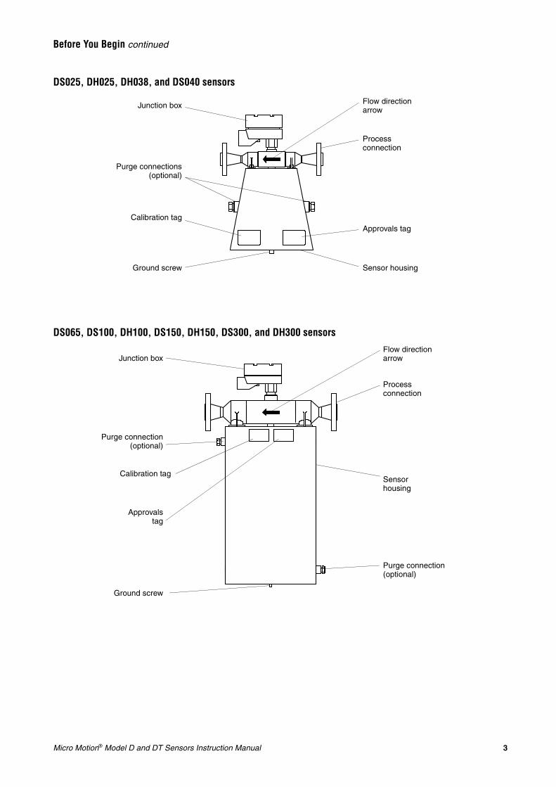
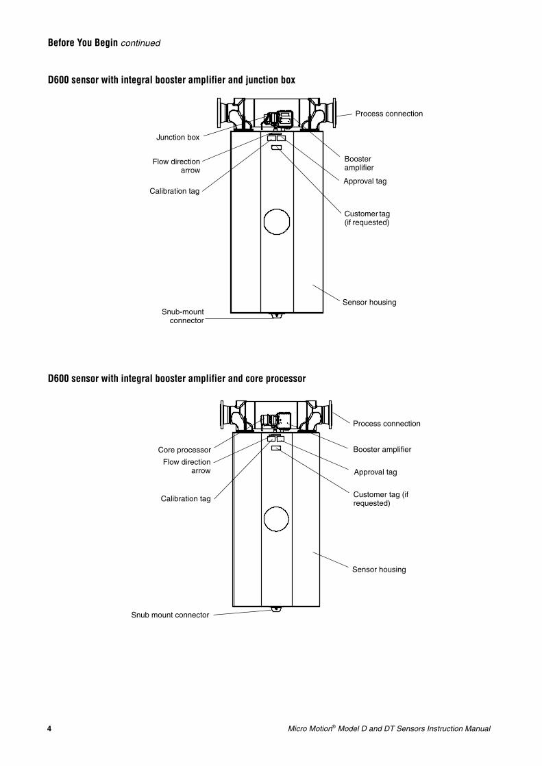
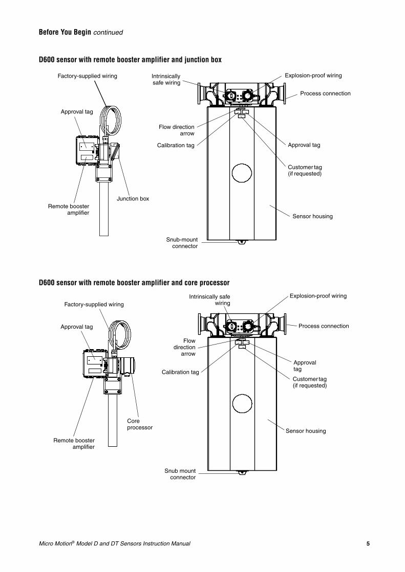
Sensor componentsComponents of the sensor are illustrated on pages 3-6.
Table 2. D600 configurations and compatible transmitters
D600 sensor configuration
Booster amplifier locationBooster amplifier wiring component
Connection to transmitter Compatible transmitters
Integral to sensor Junction box 9-wire • Model 1700/2700 (with integral core processor)
• Model 3500/3700 (9-wire)• RFT9739• RFT9712• Remote core processor
Core processor 4-wire • Model 1700/2700• Model 3500/3700 (MVD)• Model 2500• Direct host(1)
Remote from sensor Junction box 9-wire • Model 1700/2700 (with integral core processor)
• Model 3500/3700 (9-wire)• RFT9739• RFT9712• Remote core processor
Core processor 4-wire • Model 1700/2700• Model 3500/3700 (MVD)• Model 2500• Direct host(1)
(1)A direct host is a user-supplied remote controller, PLC, or other device.
Micro Motion® Model D and DT Sensors Instruction Manual 3
Before You Begin continued
DS025, DH025, DH038, and DS040 sensors
DS065, DS100, DH100, DS150, DH150, DS300, and DH300 sensors
Ground screw
Purge connections(optional)
Junction box
Sensor housing
Flow direction arrow
Process connection
Calibration tagApprovals tag
Flow direction arrow
Purge connection(optional)
Calibration tagSensor housing
Junction box
Process connection
Approvalstag
Ground screw
Purge connection (optional)
4 Micro Motion® Model D and DT Sensors Instruction Manual
Before You Begin continued
D600 sensor with integral booster amplifier and junction box
D600 sensor with integral booster amplifier and core processor
Sensor housing
Booster amplifier
Process connection
Customer tag (if requested)
Snub-mountconnector
Junction box
Flow directionarrow
Calibration tagApproval tag
Approval tag
Sensor housing
Calibration tag
Flow directionarrow
Booster amplifierCore processor
Process connection
Customer tag (if requested)
Snub mount connector
Micro Motion® Model D and DT Sensors Instruction Manual 5
Before You Begin continued
D600 sensor with remote booster amplifier and junction box
D600 sensor with remote booster amplifier and core processor
Approval tag
Sensor housing
Remote boosteramplifier
Process connection
Customer tag (if requested)
Snub-mountconnector
Junction box
Flow directionarrow
Calibration tag
Explosion-proof wiringIntrinsicallysafe wiring
Approval tag
Factory-supplied wiring
Approval tag
Explosion-proof wiringIntrinsically safewiring
Flowdirection
arrow
Core processor
Sensor housing
Approval tag
Calibration tag
Remote boosteramplifier
Customer tag (if requested)
Process connection
Snub mountconnector
Factory-supplied wiring
6 Micro Motion® Model D and DT Sensors Instruction Manual
Before You Begin continued
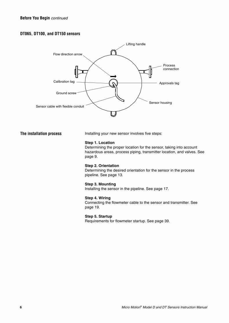
DT065, DT100, and DT150 sensors
The installation process Installing your new sensor involves five steps:
Step 1. LocationDetermining the proper location for the sensor, taking into account hazardous areas, process piping, transmitter location, and valves. See page 9.
Step 2. OrientationDetermining the desired orientation for the sensor in the process pipeline. See page 13.
Step 3. MountingInstalling the sensor in the pipeline. See page 17.
Step 4. WiringConnecting the flowmeter cable to the sensor and transmitter. See page 19.
Step 5. StartupRequirements for flowmeter startup. See page 39.
Flow direction arrow
Calibration tag
Sensor cable with flexible conduit
Process connection
Approvals tag
Ground screw
Lifting handle
Sensor housing
Micro Motion® Model D and DT Sensors Instruction Manual 7
Before You Begin continued
Additional information In addition to installation instructions, the following subjects are also covered in this manual:
• Troubleshooting for problems that might be attributable to the sensor begins on page 41.
• Purge fittings are described in Appendix A, page 55.
• Rupture disks are discussed in Appendix B, page 59.
• Maintenance of labels is covered in Appendix C, page 61.
• Return policy for Micro Motion equipment is described in Appendix D, page 65.

8 Micro Motion® Model D and DT Sensors Instruction Manual
Micro Motion® Model D and DT Sensors Instruction Manual 9
Pipe run Micro Motion sensors do not require a straight run of pipe upstream or downstream.
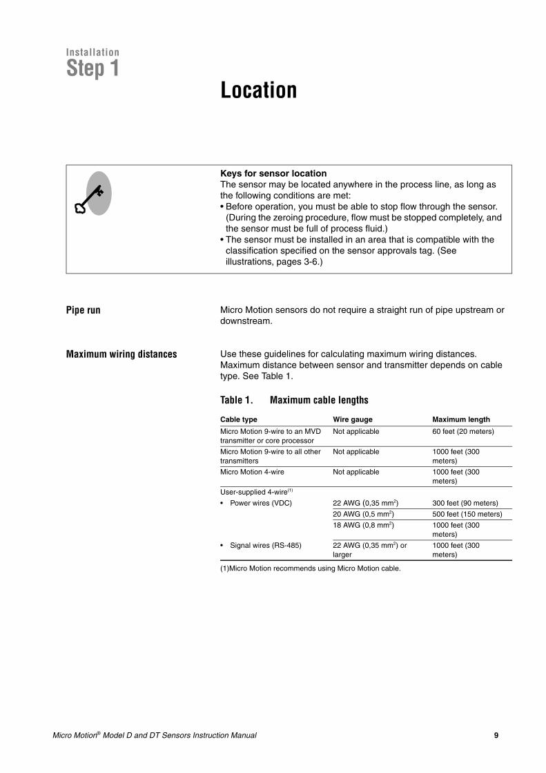
Maximum wiring distances Use these guidelines for calculating maximum wiring distances. Maximum distance between sensor and transmitter depends on cable type. See Table 1.
.
Keys for sensor locationThe sensor may be located anywhere in the process line, as long as the following conditions are met:• Before operation, you must be able to stop flow through the sensor.
(During the zeroing procedure, flow must be stopped completely, and the sensor must be full of process fluid.)
• The sensor must be installed in an area that is compatible with the classification specified on the sensor approvals tag. (See illustrations, pages 3-6.)
Table 1. Maximum cable lengths
Cable type Wire gauge Maximum length
Micro Motion 9-wire to an MVD transmitter or core processor
Not applicable 60 feet (20 meters)
Micro Motion 9-wire to all other transmitters
Not applicable 1000 feet (300 meters)
Micro Motion 4-wire Not applicable 1000 feet (300 meters)
User-supplied 4-wire(1)
(1)Micro Motion recommends using Micro Motion cable.
• Power wires (VDC) 22 AWG (0,35 mm2) 300 feet (90 meters)
20 AWG (0,5 mm2) 500 feet (150 meters)
18 AWG (0,8 mm2) 1000 feet (300 meters)
• Signal wires (RS-485) 22 AWG (0,35 mm2) or larger
1000 feet (300 meters)
Step 1Location
Installation
10 Micro Motion® Model D and DT Sensors Instruction Manual
Location continued
DT sensor junction box Model DT sensors come with a 3-foot (1 meter) pigtail of cable pre-installed. A junction box can be installed at the end of this pigtail.
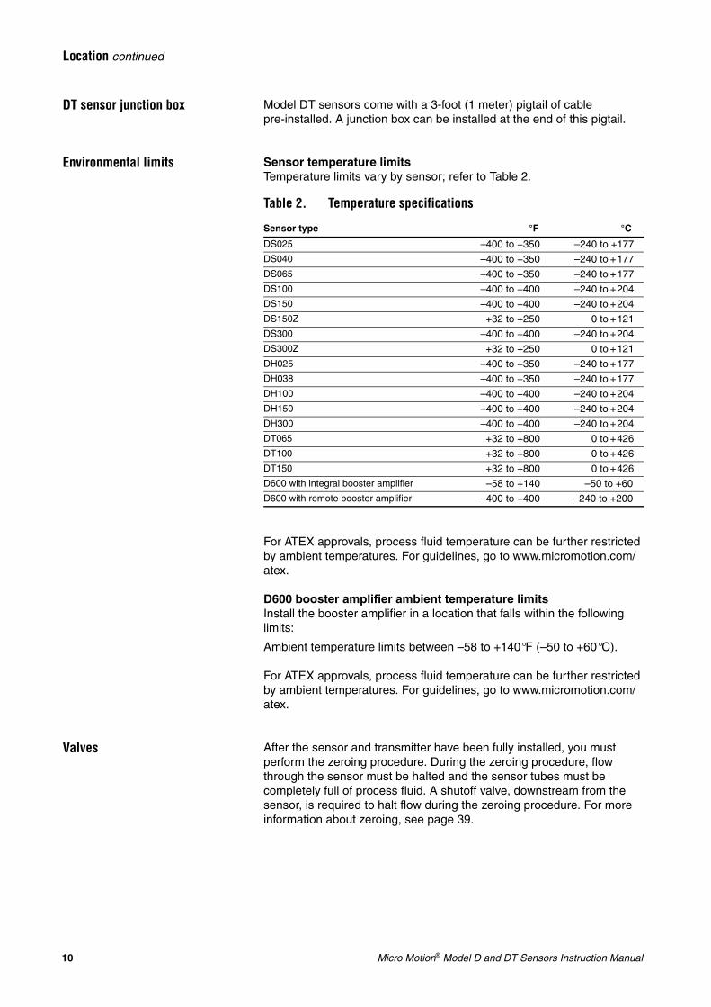
Environmental limits Sensor temperature limitsTemperature limits vary by sensor; refer to Table 2.
For ATEX approvals, process fluid temperature can be further restricted by ambient temperatures. For guidelines, go to www.micromotion.com/atex.
D600 booster amplifier ambient temperature limitsInstall the booster amplifier in a location that falls within the following limits:
Ambient temperature limits between –58 to +140°F (–50 to +60°C).
For ATEX approvals, process fluid temperature can be further restricted by ambient temperatures. For guidelines, go to www.micromotion.com/atex.
Valves After the sensor and transmitter have been fully installed, you must perform the zeroing procedure. During the zeroing procedure, flow through the sensor must be halted and the sensor tubes must be completely full of process fluid. A shutoff valve, downstream from the sensor, is required to halt flow during the zeroing procedure. For more information about zeroing, see page 39.
Table 2. Temperature specifications
Sensor type °F °C
DS025 –400 to +350 –240 to +177DS040 –400 to +350 –240 to +177DS065 –400 to +350 –240 to +177DS100 –400 to +400 –240 to +204DS150 –400 to +400 –240 to +204DS150Z +32 to +250 0 to +121DS300 –400 to +400 –240 to +204DS300Z +32 to +250 0 to +121DH025 –400 to +350 –240 to +177DH038 –400 to +350 –240 to +177DH100 –400 to +400 –240 to +204DH150 –400 to +400 –240 to +204DH300 –400 to +400 –240 to +204DT065 +32 to +800 0 to +426DT100 +32 to +800 0 to +426DT150 +32 to +800 0 to +426D600 with integral booster amplifier –58 to +140 –50 to +60D600 with remote booster amplifier –400 to +400 –240 to +200
Micro Motion® Model D and DT Sensors Instruction Manual 11
Location continued
Hazardous area installations Make sure the hazardous area specified on the sensor approvals tag is suitable for the environment in which the sensor is installed. (See illustrations on pages 3-6.) For installation in an area that requires intrinsic safety, refer to Micro Motion hazardous approval documentation, shipped with the sensor or available from the Micro Motion web site.
For hazardous installations in Europe, refer to standard EN 60079-14 if national standards do not apply.
If you don’t have access to the World Wide Web, you can obtain an I.S. manual by contacting the Micro Motion Customer Service Department:
• In the U.S.A., phone 1-800-522-MASS (1-800-522-6277), 24 hours• In Canada and Latin America, phone +1 303-527-5200 (U.S.A.)• In Asia, phone +65 6777-8211 (Singapore)• In the U.K., phone 0870 240 1978 (toll-free)• Outside the U.K., phone +31 (0) 318 495 555 (The Netherlands)

12 Micro Motion® Model D and DT Sensors Instruction Manual
Micro Motion® Model D and DT Sensors Instruction Manual 13
Installation
Step 2 Orientation
Flow direction Micro Motion sensors measure accurately regardless of flow direction as long as the sensor flow tubes remain filled with process fluid.
Flow direction arrowThe sensor has a flow direction arrow (see illustrations, pages 3-6) to help you configure the transmitter for flow direction. Process fluid flowing in the direction opposite to the flow direction arrow may cause unexpected transmitter output unless the transmitter is configured appropriately. For instructions on configuring the transmitter’s flow direction parameter, refer to the transmitter instruction manual.
Vertical pipelineIf the sensor is installed in a vertical pipeline, liquids and slurries should flow upward through the sensor. Gases may flow upward or downward.
Process fluid Typical sensor orientations are shown in the tables on the following pages:• For measuring liquids, see page 14.• For measuring gases, see page 15.• For measuring slurries, see page 16.
Keys for sensor orientationThe sensor will function properly in any orientation if the sensor flow tubes remain filled with process fluid.
14 Micro Motion® Model D and DT Sensors Instruction Manual
Orientation continued
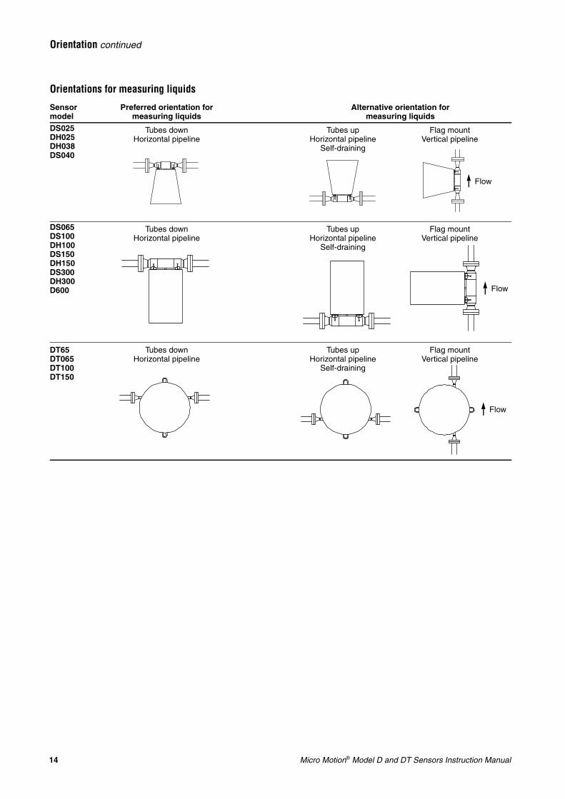
Orientations for measuring liquids
Sensor model
Preferred orientation for measuring liquids
Alternative orientation for measuring liquids
DS025DH025DH038DS040
Tubes downHorizontal pipeline
Tubes upHorizontal pipeline
Self-draining
Flag mountVertical pipeline
DS065DS100DH100DS150DH150DS300DH300D600
Tubes downHorizontal pipeline
Tubes upHorizontal pipeline
Self-draining
Flag mountVertical pipeline
DT65DT065DT100DT150
Tubes downHorizontal pipeline
Tubes upHorizontal pipeline
Self-draining
Flag mountVertical pipeline
Flow
Flow
Flow
Micro Motion® Model D and DT Sensors Instruction Manual 15
Orientation continued
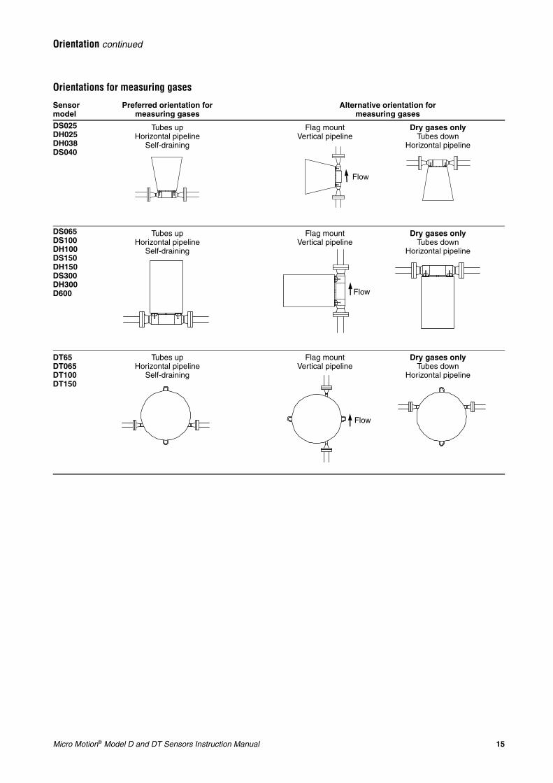
Orientations for measuring gases
Sensor model
Preferred orientation for measuring gases
Alternative orientation formeasuring gases
DS025DH025DH038DS040
Tubes upHorizontal pipeline
Self-draining
Flag mountVertical pipeline
Dry gases onlyTubes down
Horizontal pipeline
DS065DS100DH100DS150DH150DS300DH300D600
Tubes upHorizontal pipeline
Self-draining
Flag mountVertical pipeline
Dry gases onlyTubes down
Horizontal pipeline
DT65DT065DT100DT150
Tubes upHorizontal pipeline
Self-draining
Flag mountVertical pipeline
Dry gases onlyTubes down
Horizontal pipeline
Flow
Flow
Flow
16 Micro Motion® Model D and DT Sensors Instruction Manual
Orientation continued
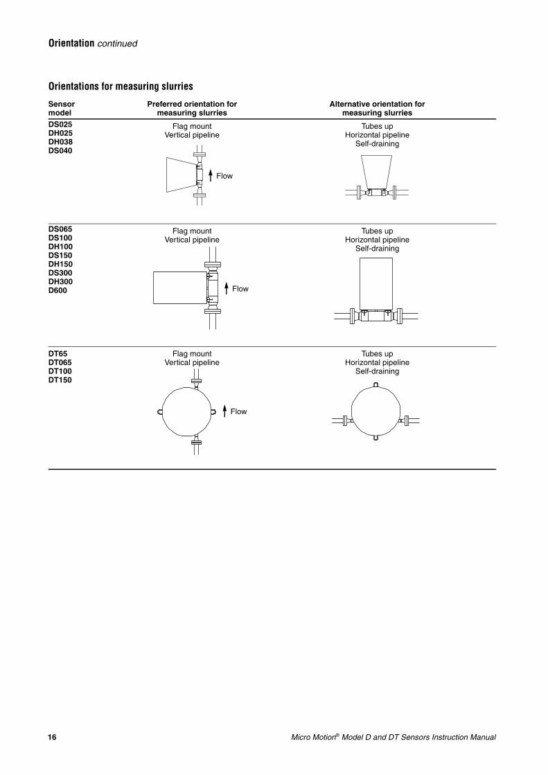
Orientations for measuring slurries
Sensor model
Preferred orientation formeasuring slurries
Alternative orientation for measuring slurries
DS025DH025DH038DS040
Flag mountVertical pipeline
Tubes upHorizontal pipeline
Self-draining
DS065DS100DH100DS150DH150DS300DH300D600
Flag mountVertical pipeline
Tubes upHorizontal pipeline
Self-draining
DT65DT065DT100DT150
Flag mountVertical pipeline
Tubes upHorizontal pipeline
Self-draining
Flow
Flow
Flow
Micro Motion® Model D and DT Sensors Instruction Manual 17
Installation
Step 3 Mounting
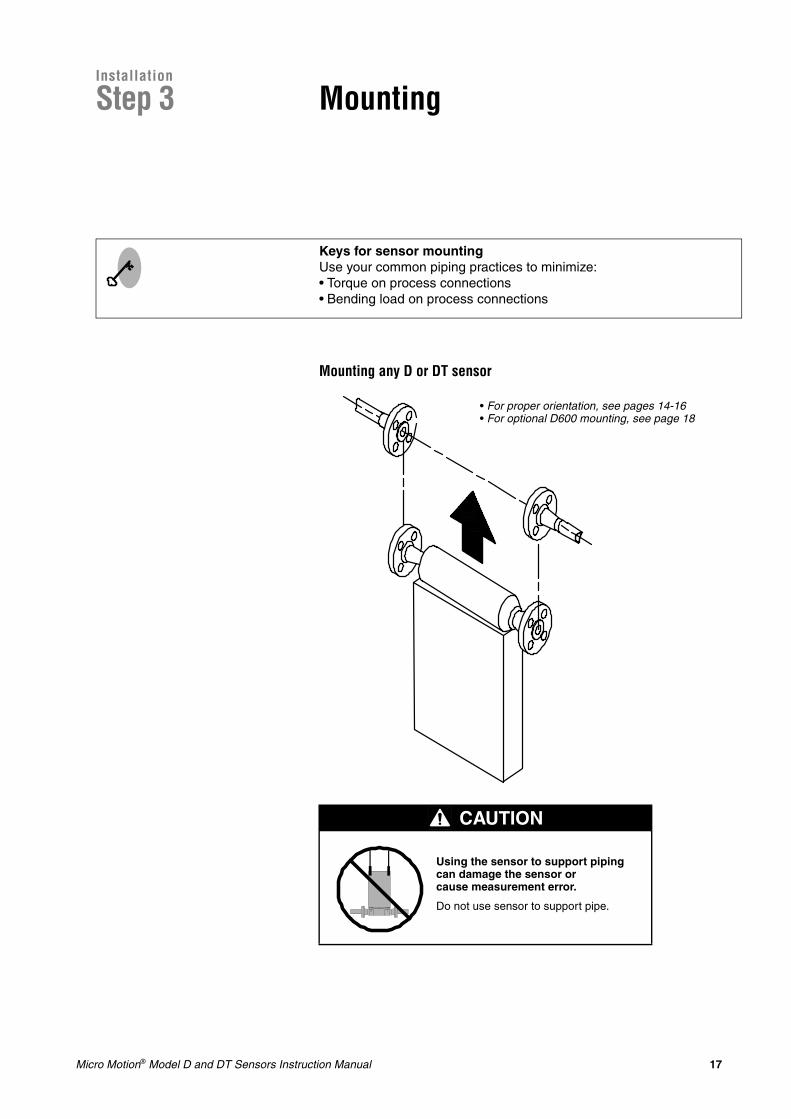
Mounting any D or DT sensor
CAUTION
Using the sensor to support piping can damage the sensor or cause measurement error.
Do not use sensor to support pipe.
Keys for sensor mountingUse your common piping practices to minimize:• Torque on process connections• Bending load on process connections
• For proper orientation, see pages 14-16• For optional D600 mounting, see page 18
18 Micro Motion® Model D and DT Sensors Instruction Manual
Mounting continued
Conduit openings If possible, install wiring with the conduit openings pointed downward to reduce the risk of condensation or excessive moisture in the housing. Otherwise, install drip legs on the cable or conduit.
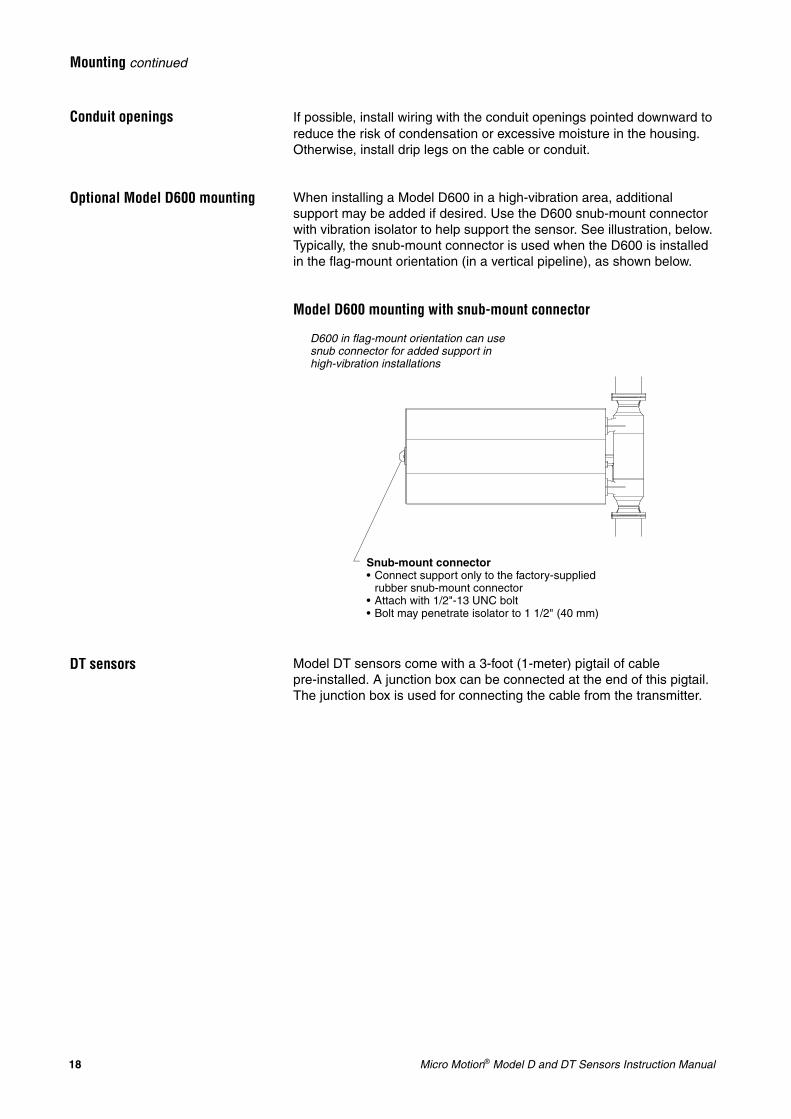
Optional Model D600 mounting When installing a Model D600 in a high-vibration area, additional support may be added if desired. Use the D600 snub-mount connector with vibration isolator to help support the sensor. See illustration, below. Typically, the snub-mount connector is used when the D600 is installed in the flag-mount orientation (in a vertical pipeline), as shown below.
Model D600 mounting with snub-mount connector
DT sensors Model DT sensors come with a 3-foot (1-meter) pigtail of cable pre-installed. A junction box can be connected at the end of this pigtail. The junction box is used for connecting the cable from the transmitter.
Snub-mount connector• Connect support only to the factory-supplied
rubber snub-mount connector• Attach with 1/2"-13 UNC bolt• Bolt may penetrate isolator to 1 1/2" (40 mm)
D600 in flag-mount orientation can use snub connector for added support in high-vibration installations
Micro Motion® Model D and DT Sensors Instruction Manual 19
Installation
Step 4 Wiring
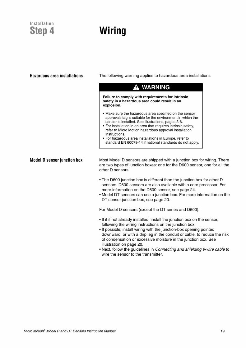
Hazardous area installations The following warning applies to hazardous area installations
Model D sensor junction box Most Model D sensors are shipped with a junction box for wiring. There are two types of junction boxes: one for the D600 sensor, one for all the other D sensors.
• The D600 junction box is different than the junction box for other D sensors. D600 sensors are also available with a core processor. For more information on the D600 sensor, see page 24.
• Model DT sensors can use a junction box. For more information on the DT sensor junction box, see page 20.
For Model D sensors (except the DT series and D600):
• If it if not already installed, install the junction box on the sensor, following the wiring instructions on the junction box.
• If possible, install wiring with the junction-box opening pointed downward, or with a drip leg in the conduit or cable, to reduce the risk of condensation or excessive moisture in the junction box. See illustration on page 20.
• Next, follow the guidelines in Connecting and shielding 9-wire cable to wire the sensor to the transmitter.
WARNING
Failure to comply with requirements for intrinsic safety in a hazardous area could result in an explosion.
• Make sure the hazardous area specified on the sensor approvals tag is suitable for the environment in which the sensor is installed. See illustrations, pages 3-6.
• For installation in an area that requires intrinsic safety, refer to Micro Motion hazardous approval installation instructions.
• For hazardous area installations in Europe, refer to standard EN 60079-14 if national standards do not apply.
20 Micro Motion® Model D and DT Sensors Instruction Manual
Wiring continued
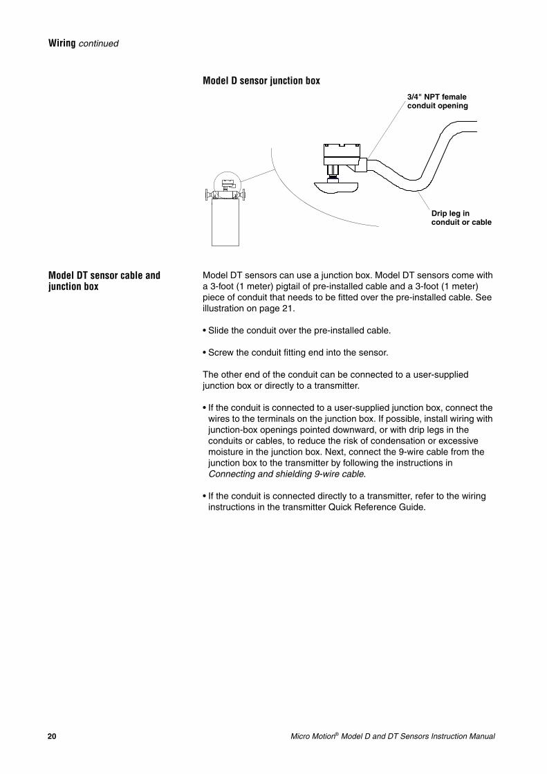
Model D sensor junction box
Model DT sensor cable and junction box
Model DT sensors can use a junction box. Model DT sensors come with a 3-foot (1 meter) pigtail of pre-installed cable and a 3-foot (1 meter) piece of conduit that needs to be fitted over the pre-installed cable. See illustration on page 21.
• Slide the conduit over the pre-installed cable.
• Screw the conduit fitting end into the sensor.
The other end of the conduit can be connected to a user-supplied junction box or directly to a transmitter.
• If the conduit is connected to a user-supplied junction box, connect the wires to the terminals on the junction box. If possible, install wiring with junction-box openings pointed downward, or with drip legs in the conduits or cables, to reduce the risk of condensation or excessive moisture in the junction box. Next, connect the 9-wire cable from the junction box to the transmitter by following the instructions in Connecting and shielding 9-wire cable.
• If the conduit is connected directly to a transmitter, refer to the wiring instructions in the transmitter Quick Reference Guide.
3/4" NPT female conduit opening
Drip leg in conduit or cable
Micro Motion® Model D and DT Sensors Instruction Manual 21
Wiring continued
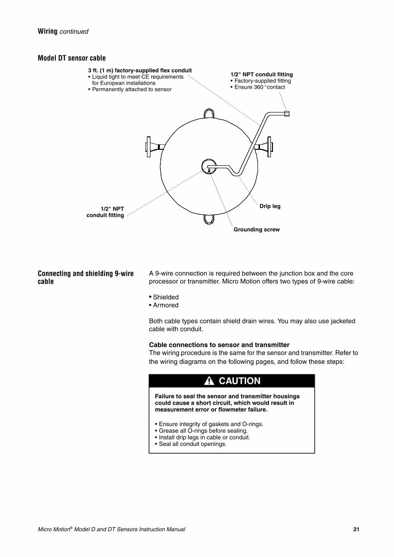
Model DT sensor cable
Connecting and shielding 9-wire cable
A 9-wire connection is required between the junction box and the core processor or transmitter. Micro Motion offers two types of 9-wire cable:
• Shielded• Armored
Both cable types contain shield drain wires. You may also use jacketed cable with conduit.
Cable connections to sensor and transmitterThe wiring procedure is the same for the sensor and transmitter. Refer to the wiring diagrams on the following pages, and follow these steps:
Drip leg1/2" NPTconduit fitting
3 ft. (1 m) factory-supplied flex conduit• Liquid tight to meet CE requirements
for European installations• Permanently attached to sensor
Grounding screw
1/2" NPT conduit fitting• Factory-supplied fitting• Ensure 360° contact
CAUTION
Failure to seal the sensor and transmitter housings could cause a short circuit, which would result in measurement error or flowmeter failure.
• Ensure integrity of gaskets and O-rings.• Grease all O-rings before sealing.• Install drip legs in cable or conduit.• Seal all conduit openings.
22 Micro Motion® Model D and DT Sensors Instruction Manual
Wiring continued
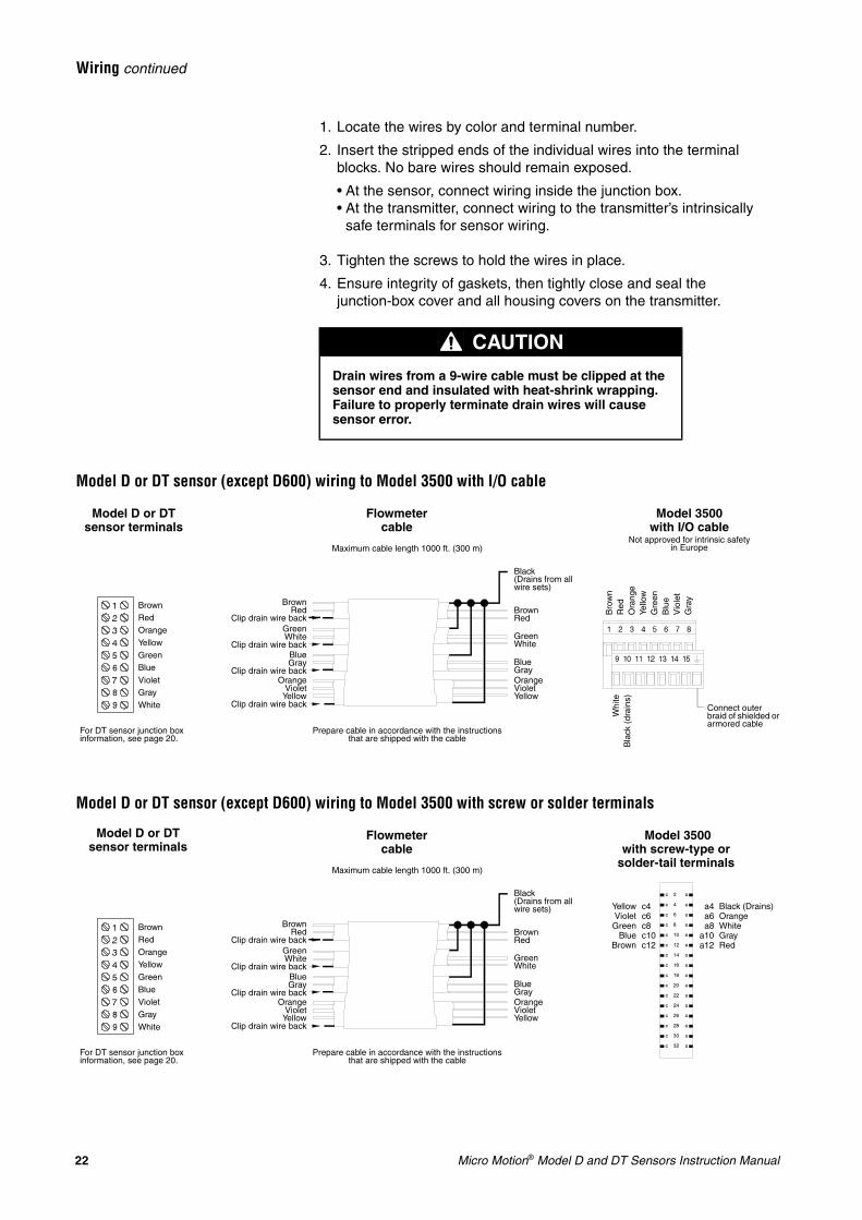
1. Locate the wires by color and terminal number.
2. Insert the stripped ends of the individual wires into the terminal blocks. No bare wires should remain exposed.
• At the sensor, connect wiring inside the junction box.• At the transmitter, connect wiring to the transmitter’s intrinsically
safe terminals for sensor wiring.
3. Tighten the screws to hold the wires in place.
4. Ensure integrity of gaskets, then tightly close and seal the junction-box cover and all housing covers on the transmitter.
Model D or DT sensor (except D600) wiring to Model 3500 with I/O cable
Model D or DT sensor (except D600) wiring to Model 3500 with screw or solder terminals
CAUTION
Drain wires from a 9-wire cable must be clipped at the sensor end and insulated with heat-shrink wrapping. Failure to properly terminate drain wires will cause sensor error.
BrownRed
Clip drain wire backGreenWhite
Clip drain wire backBlueGray
Clip drain wire backOrange
VioletYellow
Clip drain wire back
Model D or DT sensor terminals
Flowmeter cable
BrownRed
GreenWhite
BlueGrayOrangeVioletYellow
Black(Drains from all wire sets)
Maximum cable length 1000 ft. (300 m)
Prepare cable in accordance with the instructions that are shipped with the cable
BrownRedOrangeYellowGreenBlueVioletGrayWhite
Bro
wn
Red
Ora
nge
Yello
wG
reen
Blu
eV
iole
tG
ray
Whi
teB
lack
(dr
ains
)
Connect outer braid of shielded or armored cable
For DT sensor junction box information, see page 20.
Model 3500 with I/O cable
Not approved for intrinsic safety in Europe
BrownRed
Clip drain wire backGreenWhite
Clip drain wire backBlueGray
Clip drain wire backOrange
VioletYellow
Clip drain wire back
Model D or DT sensor terminals
Flowmeter cable
Model 3500 with screw-type or
solder-tail terminals
BrownRed
GreenWhite
BlueGrayOrangeVioletYellow
Black(Drains from all wire sets) Yellow
VioletGreen
BlueBrown
Black (Drains)OrangeWhiteGrayRed
Maximum cable length 1000 ft. (300 m)
Prepare cable in accordance with the instructions that are shipped with the cable
c4c6c8c10c12
a4a6a8
a10a12
BrownRedOrangeYellowGreenBlueVioletGrayWhite
For DT sensor junction box information, see page 20.
Micro Motion® Model D and DT Sensors Instruction Manual 23
Wiring continued
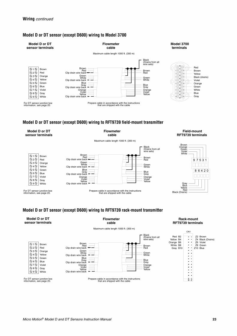
Model D or DT sensor (except D600) wiring to Model 3700
Model D or DT sensor (except D600) wiring to RFT9739 field-mount transmitter
Model D or DT sensor (except D600) wiring to RFT9739 rack-mount transmitter
BrownRed
Clip drain wire backGreenWhite
Clip drain wire backBlueGray
Clip drain wire backOrange
VioletYellow
Clip drain wire back
Model D or DT sensor terminals
Flowmeter cable
Model 3700 terminals
BrownRed
GreenWhite
BlueGrayOrangeVioletYellow
Black(Drains from all wire sets)
Maximum cable length 1000 ft. (300 m)
Prepare cable in accordance with the instructions that are shipped with the cable
BrownRedOrangeYellowGreenBlueVioletGrayWhite
RedBrownYellowBlack (drains)VioletOrangeGreenWhiteBlueGray
For DT sensor junction box information, see page 20.
9 7 5 3 1
8 6 4 2 0
BrownRed
Clip drain wire backGreenWhite
Clip drain wire backBlueGray
Clip drain wire backOrange
VioletYellow
Clip drain wire back
Model D or DT sensor terminals
Flowmeter cable
Field-mount RFT9739 terminals
BrownRed
GreenWhite
BlueGrayOrangeVioletYellow
Black(Drains from all wire sets)
BrownOrangeGreenVioletWhite
GrayBlue
YellowRed
Black (Drains)
Maximum cable length 1000 ft. (300 m)
Prepare cable in accordance with the instructions that are shipped with the cable
BrownRedOrangeYellowGreenBlueVioletGrayWhite
For DT sensor junction-box information, see page 20.
CN1
B Z
BrownRed
Clip drain wire backGreenWhite
Clip drain wire backBlueGray
Clip drain wire backOrange
VioletYellow
Clip drain wire back
Model D or DT sensor terminals
Flowmeter cable
Rack-mount RFT9739 terminals
BrownRed
GreenWhite
BlueGrayOrangeVioletYellow
Black(Drains from all wire sets)
RedYellow
OrangeWhiteGray
BrownBlack (Drains)VioletGreenBlue
Maximum cable length 1000 ft. (300 m)
Prepare cable in accordance with the instructions that are shipped with the cable
B2B4B6B8B10
Z2Z4Z6Z8
Z10
BrownRedOrangeYellowGreenBlueVioletGrayWhite
For DT sensor junction box information, see page 20.
24 Micro Motion® Model D and DT Sensors Instruction Manual
Wiring continued
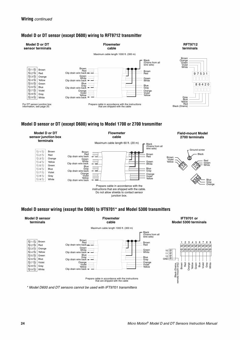
Model D or DT sensor (except D600) wiring to RFT9712 transmitter
Model D sensor or DT (except D600) wiring to Model 1700 or 2700 transmitter
Model D sensor wiring (except the D600) to IFT9701* and Model 5300 transmitters
9 7 5 3 1
8 6 4 2 0
BrownRed
Clip drain wire backGreenWhite
Clip drain wire backBlueGray
Clip drain wire backOrange
VioletYellow
Clip drain wire back
Model D or DT sensor terminals
Flowmeter cable
RFT9712 terminals
BrownRed
GreenWhite
BlueGrayOrangeVioletYellow
Black(Drains from all wire sets)
BrownOrangeGreenVioletWhite
GrayBlue
YellowRed
Black (Drains)
Maximum cable length 1000 ft. (300 m)
Prepare cable in accordance with the instructions that are shipped with the cable
BrownRedOrangeYellowGreenBlueVioletGrayWhite
For DT sensor junction box information, see page 20.
BrownRed
Clip drain wire backGreenWhite
Clip drain wire backBlueGray
Clip drain wire backOrange
VioletYellow
Clip drain wire back
Model D or DT sensor junction box
terminals
Flowmeter cable
Field-mount Model 2700 terminals
BrownRed
GreenWhite
BlueGrayOrangeVioletYellow
Black(Drains from all wire sets)
BrownViolet
Yellow
Maximum cable length 60 ft. (20 m)
Prepare cable in accordance with the instructions that are shipped with the cable.
Do not allow shields to contact sensor junction box.
BlueGrayOrange
RedGreenWhite
Ground screw
BlackBrownRedOrangeYellowGreenBlueVioletGrayWhite
10 11 12
GND
BrownRedOrangeYellowGreenBlueVioletGrayWhite
BrownRed
Clip drain wire backGreenWhite
Clip drain wire backBlueGray
Clip drain wire backOrange
VioletYellow
Clip drain wire back
Flowmeter cable
BrownRed
GreenWhite
BlueGrayOrangeVioletYellow
Black(Drains from all wire sets)
Maximum cable length 1000 ft. (300 m)
Prepare cable in accordance with the instructions that are shipped with the cable
Bla
ck (
Dra
ins,
rem
ote-
mou
nt o
nly)
Bro
wn
Red
Ora
nge
Yello
w
Gre
en
Blu
e
Vio
let
Gra
y
Whi
te
Model D sensor terminals
* Model D600 and DT sensors cannot be used with IFT9701 transmitters
IFT9701 or Model 5300 terminals
Micro Motion® Model D and DT Sensors Instruction Manual 25
Wiring continued
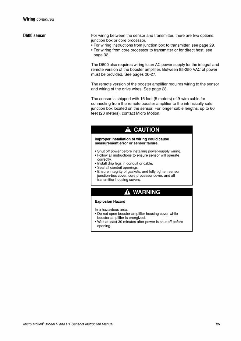
D600 sensor For wiring between the sensor and transmitter, there are two options: junction box or core processor.• For wiring instructions from junction box to transmitter, see page 29.• For wiring from core processor to transmitter or for direct host, see
page 32.
The D600 also requires wiring to an AC power supply for the integral and remote version of the booster amplifier. Between 85-250 VAC of power must be provided. See pages 26-27.
The remote version of the booster amplifier requires wiring to the sensor and wiring of the drive wires. See page 28.
The sensor is shipped with 16 feet (5 meters) of 9-wire cable for connecting from the remote booster amplifier to the intrinsically safe junction box located on the sensor. For longer cable lengths, up to 60 feet (20 meters), contact Micro Motion.
CAUTION
Improper installation of wiring could cause measurement error or sensor failure.
• Shut off power before installing power-supply wiring.• Follow all instructions to ensure sensor will operate
correctly.• Install drip legs in conduit or cable.• Seal all conduit openings.• Ensure integrity of gaskets, and fully tighten sensor
junction-box cover, core processor cover, and all transmitter housing covers.
WARNING
Explosion Hazard
In a hazardous area:• Do not open booster amplifier housing cover while
booster amplifier is energized.• Wait at least 30 minutes after power is shut off before
opening.
26 Micro Motion® Model D and DT Sensors Instruction Manual
Wiring continued
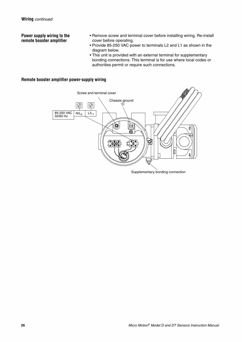
Power supply wiring to the remote booster amplifier
• Remove screw and terminal cover before installing wiring. Re-install cover before operating.
• Provide 85-250 VAC power to terminals L2 and L1 as shown in the diagram below.
• This unit is provided with an external terminal for supplementary bonding connections. This terminal is for use where local codes or authorities permit or require such connections.
Remote booster amplifier power-supply wiring
Screw and terminal cover
Chassis ground
L/L1N/L285-250 VAC50/60 Hz
Supplementary bonding connection
Micro Motion® Model D and DT Sensors Instruction Manual 27
Wiring continued
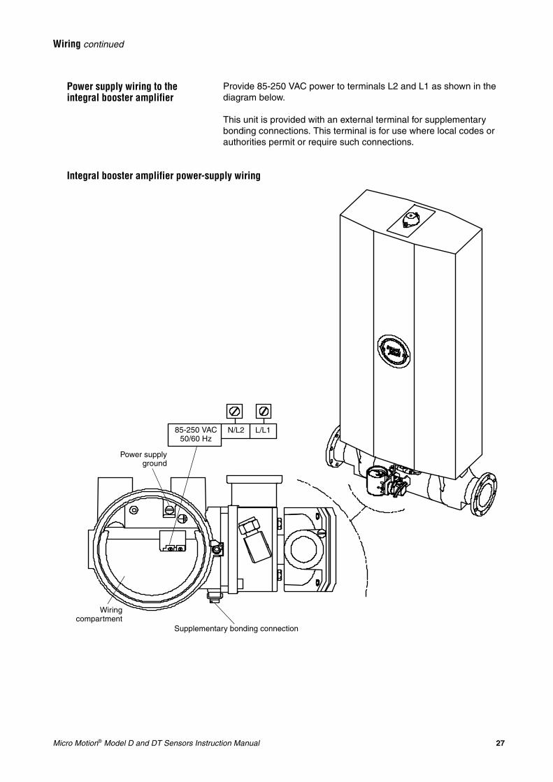
Power supply wiring to the integral booster amplifier
Provide 85-250 VAC power to terminals L2 and L1 as shown in the diagram below.
This unit is provided with an external terminal for supplementary bonding connections. This terminal is for use where local codes or authorities permit or require such connections.
Integral booster amplifier power-supply wiring
85-250 VAC50/60 Hz
N/L2 L/L1
Power supplyground
Wiringcompartment
Supplementary bonding connection
28 Micro Motion® Model D and DT Sensors Instruction Manual
Wiring continued
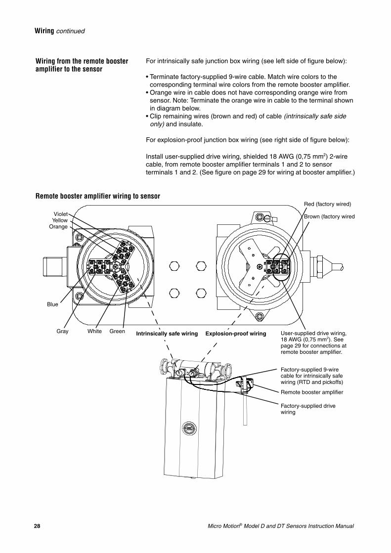
Wiring from the remote booster amplifier to the sensor
For intrinsically safe junction box wiring (see left side of figure below):
• Terminate factory-supplied 9-wire cable. Match wire colors to the corresponding terminal wire colors from the remote booster amplifier.
• Orange wire in cable does not have corresponding orange wire from sensor. Note: Terminate the orange wire in cable to the terminal shown in diagram below.
• Clip remaining wires (brown and red) of cable (intrinsically safe side only) and insulate.
For explosion-proof junction box wiring (see right side of figure below):
Install user-supplied drive wiring, shielded 18 AWG (0,75 mm2) 2-wire cable, from remote booster amplifier terminals 1 and 2 to sensor terminals 1 and 2. (See figure on page 29 for wiring at booster amplifier.)
Remote booster amplifier wiring to sensor
User-supplied drive wiring, 18 AWG (0,75 mm2). See page 29 for connections at remote booster amplifier.
White
Blue
VioletYellow
Orange
Red (factory wired)
Brown (factory wired)
Factory-supplied drive wiring
Gray
Factory-supplied 9-wire cable for intrinsically safe wiring (RTD and pickoffs)
Remote booster amplifier
Green Explosion-proof wiringIntrinsically safe wiring
12
Micro Motion® Model D and DT Sensors Instruction Manual 29
Wiring continued
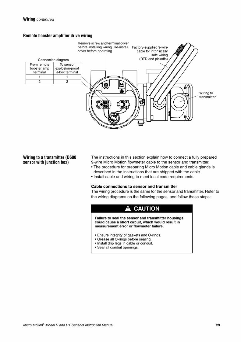
Remote booster amplifier drive wiring
Wiring to a transmitter (D600 sensor with junction box)
The instructions in this section explain how to connect a fully prepared 9-wire Micro Motion flowmeter cable to the sensor and transmitter.• The procedure for preparing Micro Motion cable and cable glands is
described in the instructions that are shipped with the cable.• Install cable and wiring to meet local code requirements.
Cable connections to sensor and transmitterThe wiring procedure is the same for the sensor and transmitter. Refer to the wiring diagrams on the following pages, and follow these steps:
Factory-supplied 9-wirecable for intrinsically
safe wiring(RTD and pickoffs)
Wiring to transmitter
Remove screw and terminal cover before installing wiring. Re-install cover before operating
Connection diagramFrom remote booster amp
terminal
To sensor explosion-proof J-box terminal
1 12 2
CAUTION
Failure to seal the sensor and transmitter housings could cause a short circuit, which would result in measurement error or flowmeter failure.
• Ensure integrity of gaskets and O-rings.• Grease all O-rings before sealing.• Install drip legs in cable or conduit.• Seal all conduit openings.
30 Micro Motion® Model D and DT Sensors Instruction Manual
Wiring continued
1. Locate the wires by color and terminal number.
2. Insert the stripped ends of the individual wires into the terminal blocks. No bare wires should remain exposed.
• At the sensor, connect wiring inside the junction box.• At the transmitter, connect wiring to the transmitter’s intrinsically
safe terminals for sensor wiring.3. Tighten the screws to hold the wires in place.
4. Ensure integrity of gaskets, then tightly close and seal the junction-box cover and all housing covers on the transmitter.
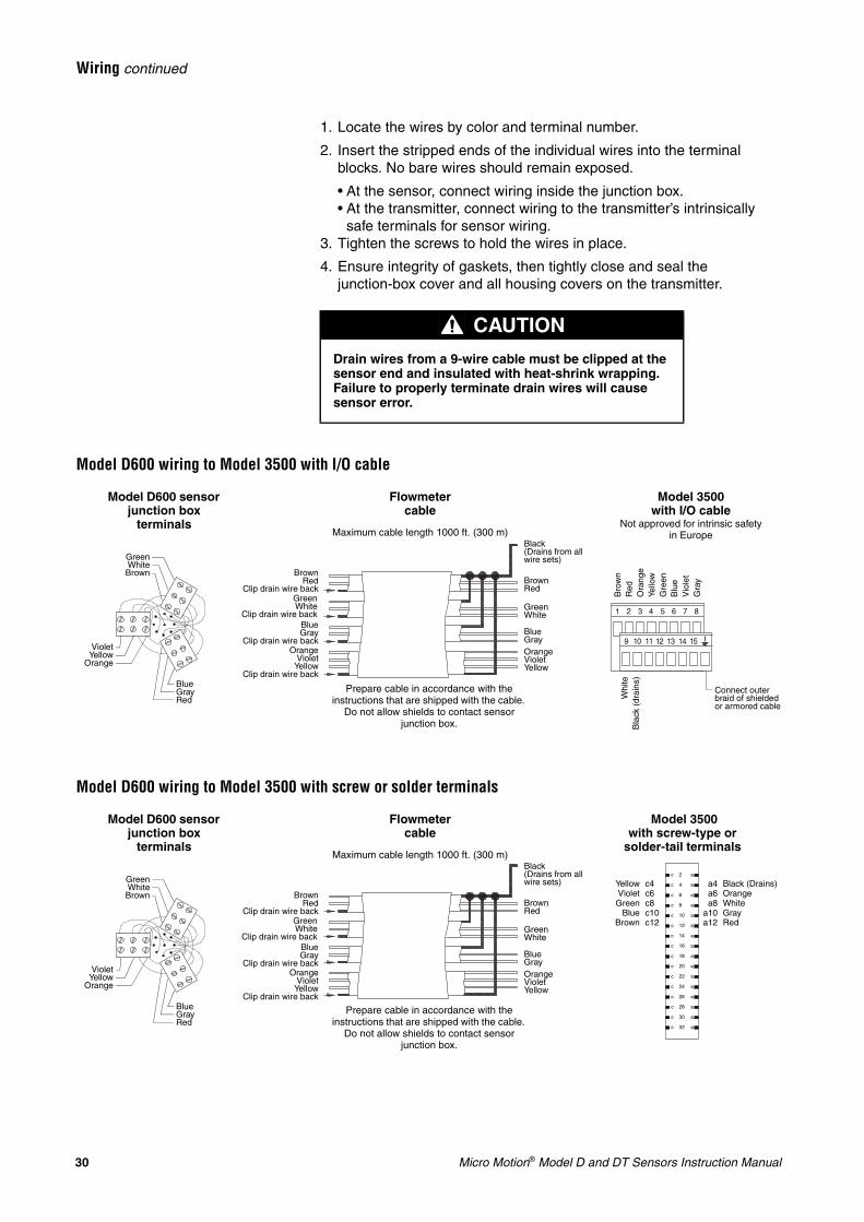
Model D600 wiring to Model 3500 with I/O cable
Model D600 wiring to Model 3500 with screw or solder terminals
CAUTION
Drain wires from a 9-wire cable must be clipped at the sensor end and insulated with heat-shrink wrapping. Failure to properly terminate drain wires will cause sensor error.
Bro
wn
Red
Ora
nge
Yello
wG
reen
Blu
eV
iole
tG
ray
Whi
teB
lack
(dr
ains
)
Connect outer braid of shielded or armored cable
BrownRed
Clip drain wire backGreenWhite
Clip drain wire backBlueGray
Clip drain wire backOrange
VioletYellow
Clip drain wire back
Flowmeter cable
BrownRed
GreenWhite
BlueGrayOrangeVioletYellow
Black(Drains from all wire sets)
Maximum cable length 1000 ft. (300 m)
GreenWhiteBrown
VioletYellow
Orange
BlueGrayRed
Model D600 sensor junction box
terminals
Model 3500 with I/O cable
Not approved for intrinsic safety in Europe
Prepare cable in accordance with the instructions that are shipped with the cable.
Do not allow shields to contact sensor junction box.
Model 3500 with screw-type or
solder-tail terminals
YellowVioletGreen
BlueBrown
Black (Drains)OrangeWhiteGrayRed
c4c6c8c10c12
a4a6a8
a10a12
BrownRed
Clip drain wire backGreenWhite
Clip drain wire backBlueGray
Clip drain wire backOrange
VioletYellow
Clip drain wire back
Flowmeter cable
BrownRed
GreenWhite
BlueGrayOrangeVioletYellow
Black(Drains from all wire sets)
Maximum cable length 1000 ft. (300 m)
GreenWhiteBrown
VioletYellow
Orange
BlueGrayRed
Model D600 sensor junction box
terminals
Prepare cable in accordance with the instructions that are shipped with the cable.
Do not allow shields to contact sensor junction box.
Micro Motion® Model D and DT Sensors Instruction Manual 31
Wiring continued
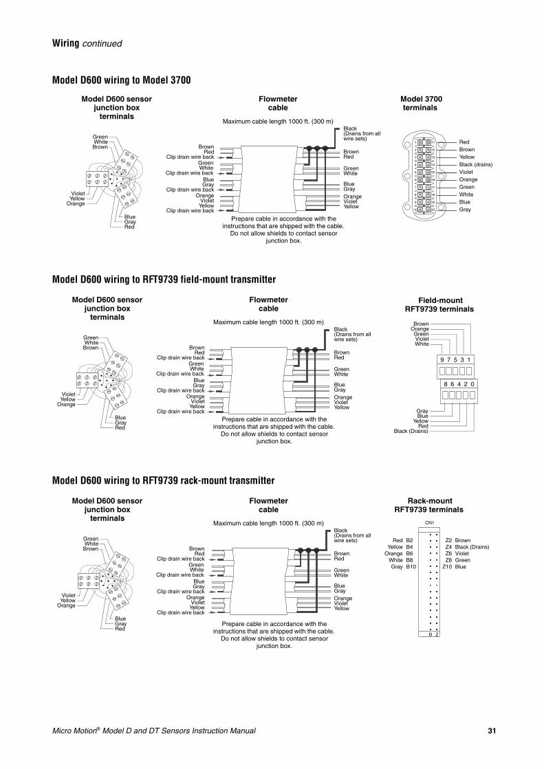
Model D600 wiring to Model 3700
Model D600 wiring to RFT9739 field-mount transmitter
Model D600 wiring to RFT9739 rack-mount transmitter
Model 3700 terminals
RedBrownYellowBlack (drains)VioletOrangeGreenWhiteBlueGray
BrownRed
Clip drain wire backGreenWhite
Clip drain wire backBlueGray
Clip drain wire backOrange
VioletYellow
Clip drain wire back
Flowmeter cable
BrownRed
GreenWhite
BlueGrayOrangeVioletYellow
Black(Drains from all wire sets)
Maximum cable length 1000 ft. (300 m)
GreenWhiteBrown
VioletYellow
Orange
BlueGrayRed
Model D600 sensor junction box
terminals
Prepare cable in accordance with the instructions that are shipped with the cable.
Do not allow shields to contact sensor junction box.
GreenWhiteBrown
VioletYellow
Orange
BlueGrayRed
BrownRed
Clip drain wire backGreenWhite
Clip drain wire backBlueGray
Clip drain wire backOrange
VioletYellow
Clip drain wire back
Model D600 sensor junction box
terminals
Flowmeter cable
Field-mount RFT9739 terminals
BrownRed
GreenWhite
BlueGrayOrangeVioletYellow
Black(Drains from all wire sets)
BrownOrangeGreenVioletWhite
GrayBlue
YellowRed
Black (Drains)
Maximum cable length 1000 ft. (300 m)
Prepare cable in accordance with the instructions that are shipped with the cable.
Do not allow shields to contact sensor junction box.
Rack-mount RFT9739 terminals
RedYellow
OrangeWhiteGray
BrownBlack (Drains)VioletGreenBlue
B2B4B6B8B10
Z2Z4Z6Z8
Z10
BrownRed
Clip drain wire backGreenWhite
Clip drain wire backBlueGray
Clip drain wire backOrange
VioletYellow
Clip drain wire back
Flowmeter cable
BrownRed
GreenWhite
BlueGrayOrangeVioletYellow
Black(Drains from all wire sets)
Maximum cable length 1000 ft. (300 m)
GreenWhiteBrown
VioletYellow
Orange
BlueGrayRed
Model D600 sensor junction box
terminals
Prepare cable in accordance with the instructions that are shipped with the cable.
Do not allow shields to contact sensor junction box.
32 Micro Motion® Model D and DT Sensors Instruction Manual
Wiring continued
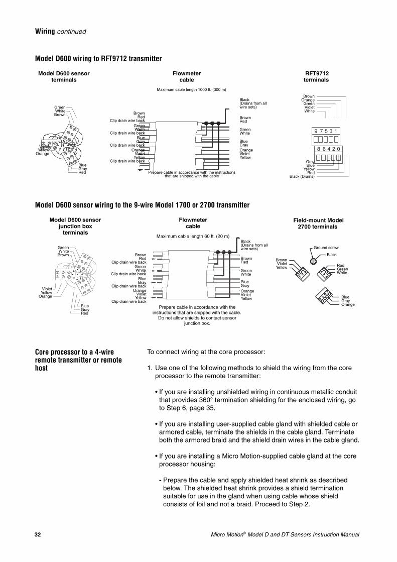
Model D600 wiring to RFT9712 transmitter
Model D600 sensor wiring to the 9-wire Model 1700 or 2700 transmitter
Core processor to a 4-wire remote transmitter or remote host
To connect wiring at the core processor:
1. Use one of the following methods to shield the wiring from the core processor to the remote transmitter:
• If you are installing unshielded wiring in continuous metallic conduit that provides 360° termination shielding for the enclosed wiring, go to Step 6, page 35.
• If you are installing user-supplied cable gland with shielded cable or armored cable, terminate the shields in the cable gland. Terminate both the armored braid and the shield drain wires in the cable gland.
• If you are installing a Micro Motion-supplied cable gland at the core processor housing:
- Prepare the cable and apply shielded heat shrink as described below. The shielded heat shrink provides a shield termination suitable for use in the gland when using cable whose shield consists of foil and not a braid. Proceed to Step 2.
9 7 5 3 1
8 6 4 2 0
9 7 5 3 1
8 6 4 2 0
9 7 5 3 1
8 6 4 2 0
BrownRed
Clip drain wire backGreenWhite
Clip drain wire backBlueGray
Clip drain wire backOrange
VioletYellow
Clip drain wire back
Model D600 sensor terminals
Flowmeter cable
RFT9712 terminals
BrownRed
GreenWhite
BlueGrayOrangeVioletYellow
Black(Drains from all wire sets)
BrownOrangeGreenVioletWhite
GrayBlue
YellowRed
Black (Drains)
Maximum cable length 1000 ft. (300 m)
Prepare cable in accordance with the instructions that are shipped with the cable
GreenWhiteBrown
VioletYellow
Orange
BlueGrayRed
GreenWhiteBrown
VioletYellow
Orange
BlueGrayRed
BrownRed
Clip drain wire backGreenWhite
Clip drain wire backBlueGray
Clip drain wire backOrange
VioletYellow
Clip drain wire back
Model D600 sensor junction box
terminals
Flowmeter cable
Field-mount Model 2700 terminals
BrownRed
GreenWhite
BlueGrayOrangeVioletYellow
Black(Drains from all wire sets)
BrownViolet
Yellow
Maximum cable length 60 ft. (20 m)
Prepare cable in accordance with the instructions that are shipped with the cable.
Do not allow shields to contact sensor junction box.
BlueGrayOrange
RedGreenWhite
Ground screw
Black
Micro Motion® Model D and DT Sensors Instruction Manual 33
Wiring continued
- With armored cable, where the shield consists of braid, prepare the cable as described below, but do not apply heat shrink. Proceed to Step 2.
2. Remove the cover from the core processor.
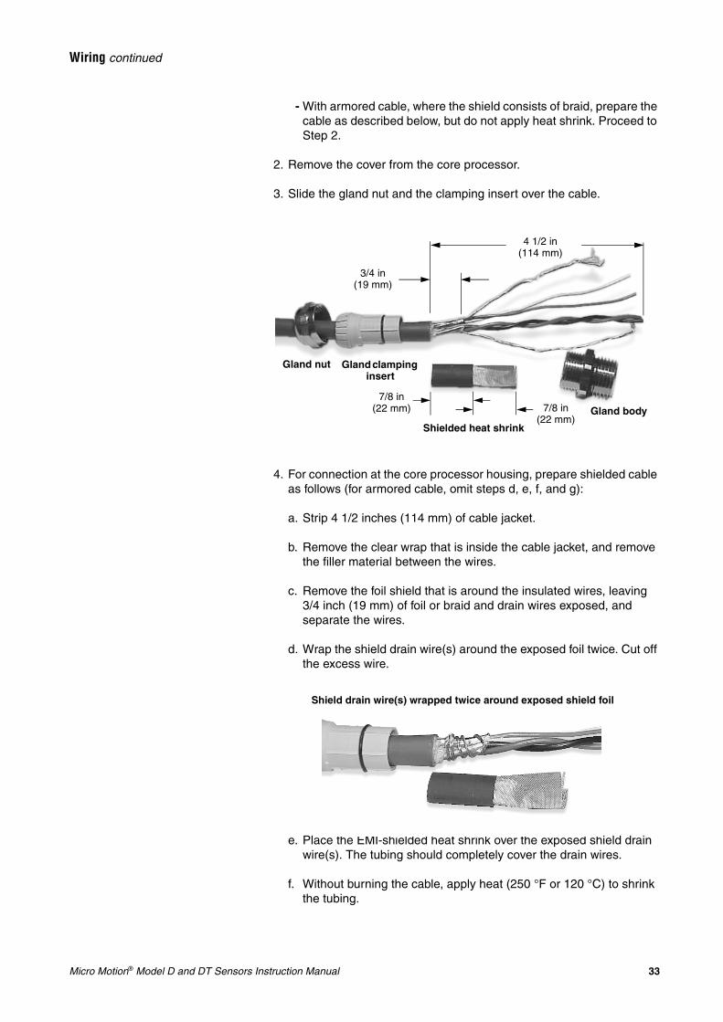
3. Slide the gland nut and the clamping insert over the cable.
4. For connection at the core processor housing, prepare shielded cable as follows (for armored cable, omit steps d, e, f, and g):
a. Strip 4 1/2 inches (114 mm) of cable jacket.
b. Remove the clear wrap that is inside the cable jacket, and remove the filler material between the wires.
c. Remove the foil shield that is around the insulated wires, leaving3/4 inch (19 mm) of foil or braid and drain wires exposed, and separate the wires.
d. Wrap the shield drain wire(s) around the exposed foil twice. Cut off the excess wire.
e. Place the EMI-shielded heat shrink over the exposed shield drain wire(s). The tubing should completely cover the drain wires.
f. Without burning the cable, apply heat (250 °F or 120 °C) to shrink the tubing.
4 1/2 in(114 mm)
3/4 in(19 mm)
7/8 in (22 mm) 7/8 in
(22 mm)Shielded heat shrink
Gland body
Gland nut Gland clamping insert
Shield drain wire(s) wrapped twice around exposed shield foil
34 Micro Motion® Model D and DT Sensors Instruction Manual
Wiring continued
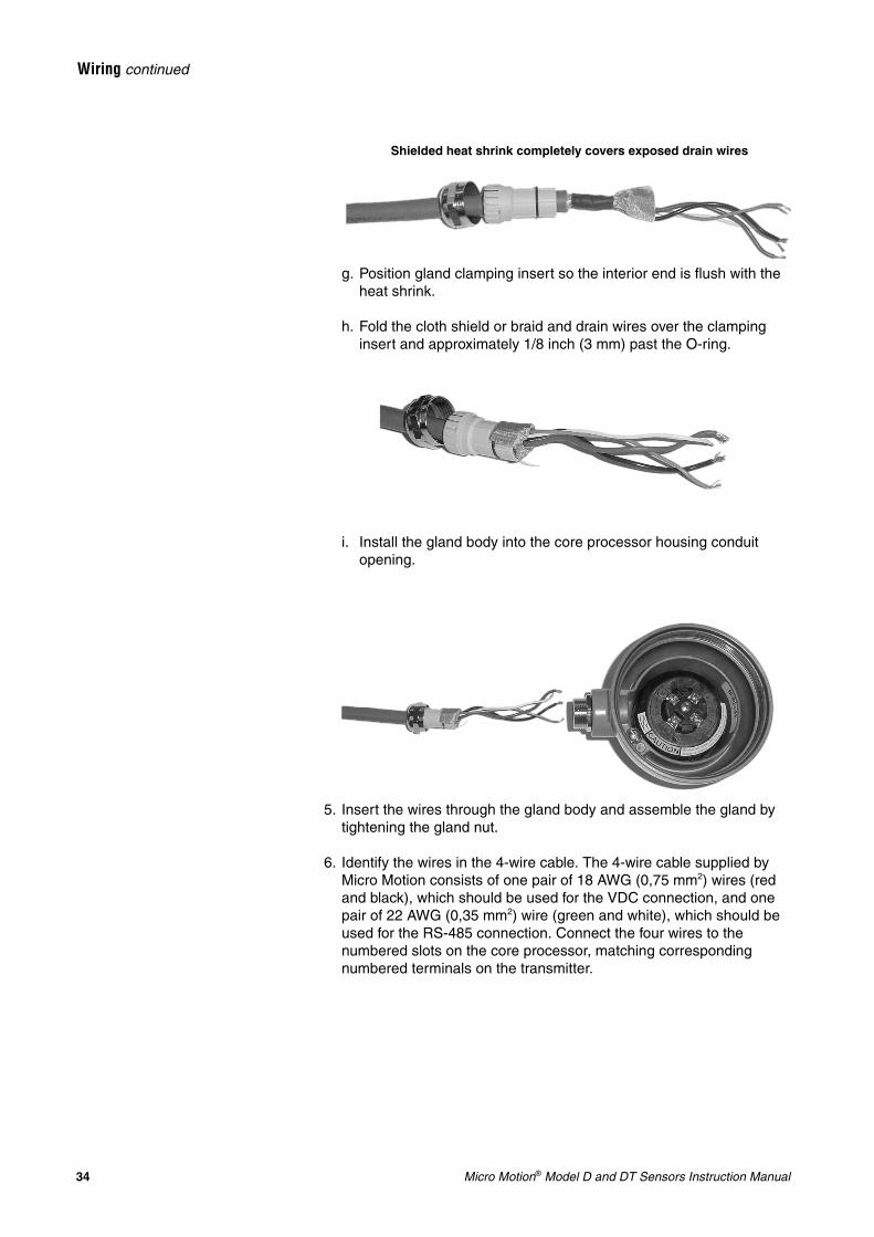
g. Position gland clamping insert so the interior end is flush with the heat shrink.
h. Fold the cloth shield or braid and drain wires over the clamping insert and approximately 1/8 inch (3 mm) past the O-ring.
i. Install the gland body into the core processor housing conduit opening.
5. Insert the wires through the gland body and assemble the gland by tightening the gland nut.
6. Identify the wires in the 4-wire cable. The 4-wire cable supplied by Micro Motion consists of one pair of 18 AWG (0,75 mm2) wires (red and black), which should be used for the VDC connection, and one pair of 22 AWG (0,35 mm2) wire (green and white), which should be used for the RS-485 connection. Connect the four wires to the numbered slots on the core processor, matching corresponding numbered terminals on the transmitter.
Shielded heat shrink completely covers exposed drain wires
Micro Motion® Model D and DT Sensors Instruction Manual 35
Wiring continued
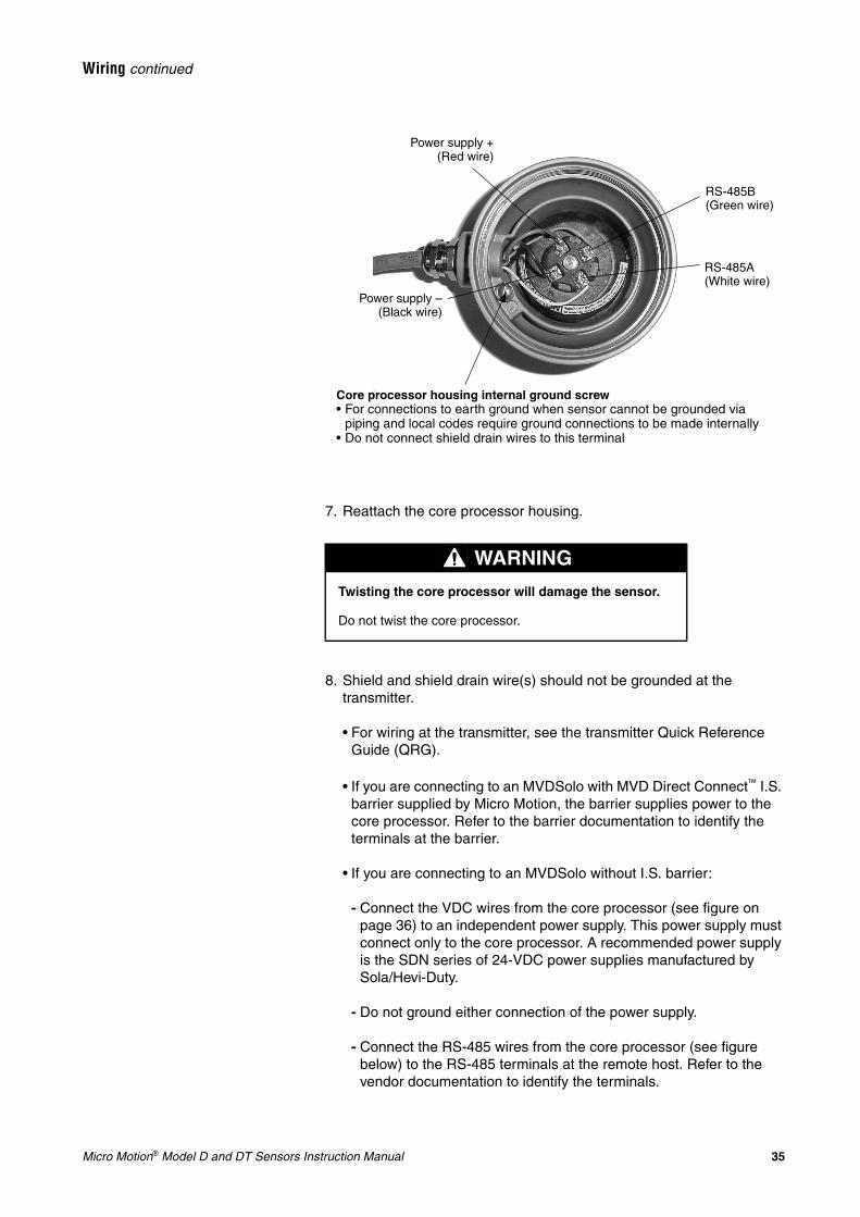
7. Reattach the core processor housing.
8. Shield and shield drain wire(s) should not be grounded at the transmitter.
• For wiring at the transmitter, see the transmitter Quick Reference Guide (QRG).
• If you are connecting to an MVDSolo with MVD Direct Connect™ I.S. barrier supplied by Micro Motion, the barrier supplies power to the core processor. Refer to the barrier documentation to identify the terminals at the barrier.
• If you are connecting to an MVDSolo without I.S. barrier:
- Connect the VDC wires from the core processor (see figure on page 36) to an independent power supply. This power supply must connect only to the core processor. A recommended power supply is the SDN series of 24-VDC power supplies manufactured by Sola/Hevi-Duty.
- Do not ground either connection of the power supply.
- Connect the RS-485 wires from the core processor (see figure below) to the RS-485 terminals at the remote host. Refer to the vendor documentation to identify the terminals.
WARNING
Twisting the core processor will damage the sensor.
Do not twist the core processor.
Power supply +(Red wire)
Power supply –(Black wire)
RS-485A (White wire)
RS-485B (Green wire)
Core processor housing internal ground screw• For connections to earth ground when sensor cannot be grounded via
piping and local codes require ground connections to be made internally• Do not connect shield drain wires to this terminal
36 Micro Motion® Model D and DT Sensors Instruction Manual
Wiring continued
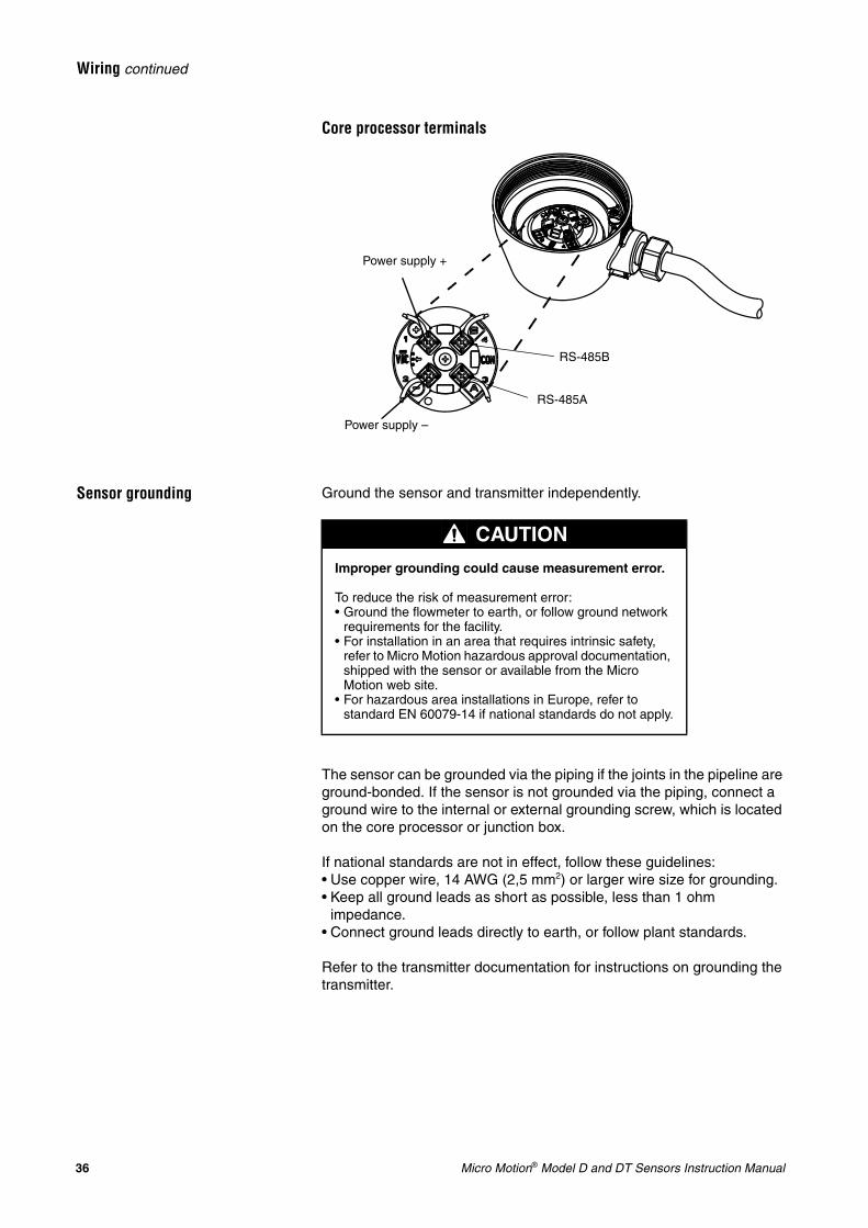
Core processor terminals
Sensor grounding Ground the sensor and transmitter independently.
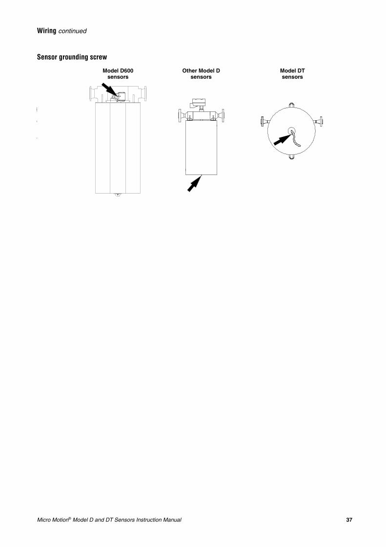
The sensor can be grounded via the piping if the joints in the pipeline are ground-bonded. If the sensor is not grounded via the piping, connect a ground wire to the internal or external grounding screw, which is located on the core processor or junction box.
If national standards are not in effect, follow these guidelines:• Use copper wire, 14 AWG (2,5 mm2) or larger wire size for grounding.• Keep all ground leads as short as possible, less than 1 ohm
impedance.• Connect ground leads directly to earth, or follow plant standards.
Refer to the transmitter documentation for instructions on grounding the transmitter.
Power supply +
Power supply –
RS-485B
RS-485A
CAUTION
Improper grounding could cause measurement error.
To reduce the risk of measurement error:• Ground the flowmeter to earth, or follow ground network
requirements for the facility.• For installation in an area that requires intrinsic safety,
refer to Micro Motion hazardous approval documentation, shipped with the sensor or available from the Micro Motion web site.
• For hazardous area installations in Europe, refer to standard EN 60079-14 if national standards do not apply.
Micro Motion® Model D and DT Sensors Instruction Manual 37
Wiring continued
Sensor grounding screw
Other Model D sensors
Model DT sensors
Model D600 sensors

38 Micro Motion® Model D and DT Sensors Instruction Manual
Micro Motion® Model D and DT Sensors Instruction Manual 39
Installation
Step 5 Startup
Zeroing After the flowmeter has been fully installed, you must perform the zeroing procedure. Flowmeter zeroing establishes flowmeter response to zero flow and sets a baseline for flow measurement. Refer to the transmitter instruction manual for information on performing the zeroing procedure.
Configuration, calibration, and characterization
You can use the transmitter to configure, calibrate, and characterize the meter. For more information, refer to the transmitter instruction manuals.
The following information explains the difference between configuration, calibration, and characterization. Certain parameters might require configuration even when calibration is not necessary.
Configuration parameters include such items as flowmeter tag, measurement units, flow direction, damping values, and slug flow parameters. If requested at time of order, the meter is configured at the factory according to customer specifications.
Calibration accounts for the flowmeter’s sensitivity to flow, density, and temperature. Calibration is done at the factory.
Characterization is the process of entering calibration factors for flow, density, and temperature directly into transmitter memory, instead of performing field calibration procedures. Calibration factors can be found on the sensor serial number tag and on the certificate that is shipped with the sensor.
For instructions about flowmeter configuration, calibration, and characterization, see the manual that was shipped with the transmitter.
If the sensor and transmitter are ordered together as a Coriolis flowmeter, the factory has characterized the meter — no additional characterization is necessary. If either the sensor or transmitter is replaced, characterization is required.
40 Micro Motion® Model D and DT Sensors Instruction Manual
Startup continued
Customer Service The Micro Motion Customer Service Department is available for assistance with flowmeter startup if you experience problems you cannot solve on your own.
If possible, provide us with the model numbers and/or serial numbers of your Micro Motion equipment, which will assist us in answering your questions.• In the U.S.A., phone 1-800-522-MASS (1-800-522-6277), 24 hours• In Canada and Latin America, phone +1 303-527-5200 (U.S.A.)• In Asia, phone +65 6777-8211 (Singapore)• In the U.K., phone 0870 240 1978 (toll-free)• Outside the U.K., phone +31 (0) 318 495 555 (The Netherlands)• Or visit our website at www.micromotion.com.
Micro Motion® Model D and DT Sensors Instruction Manual 41
Troubleshooting
General information Most troubleshooting is performed at the transmitter. However, the following troubleshooting topics are described in this manual:• Zero drift, page 42• Erratic flow rate, page 43• Inaccurate flow rate or batch total, page 44• Inaccurate density reading, page 45• Inaccurate temperature reading, page 46
If you cannot find the problem you are looking for, check the transmitter instruction manual.
To troubleshoot the flowmeter, you might need a digital multimeter (DMM) or similar device, the transmitter display, if it has one, and one of the following:• HART Communicator• ProLink or ProLink II software• AMS software• Modbus master controller (RFT9739, Series 1000, or Series 2000)• Fieldbus host controller (Series 1000 or Series 2000)• Profibus-PA host controller (Series 1000 or Series 2000)If you cannot find the problem you are looking for, or if troubleshooting fails to reveal the problem, contact the Micro Motion Customer Service Department.
If possible, provide us with the model numbers and/or serial numbers of your Micro Motion equipment, which will assist us in answering your questions.• In the U.S.A., phone 1-800-522-MASS (1-800-522-6277), 24 hours• In Canada and Latin America, phone +1 303-527-5200 (U.S.A.)• In Asia, phone +65 6777-8211 (Singapore)• In the U.K., phone 0870 240 1978 (toll-free)• Outside the U.K., phone +31 (0) 318 495 555 (The Netherlands)
42 Micro Motion® Model D and DT Sensors Instruction Manual
Troubleshooting continued
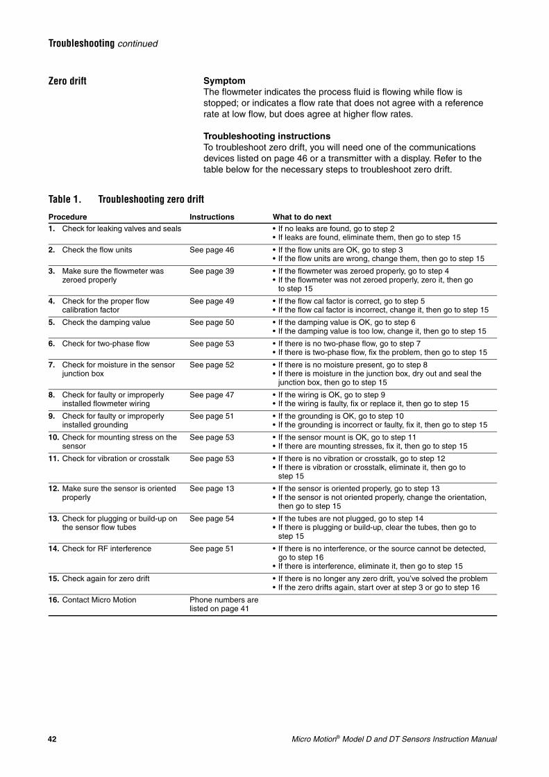
Zero drift SymptomThe flowmeter indicates the process fluid is flowing while flow is stopped; or indicates a flow rate that does not agree with a reference rate at low flow, but does agree at higher flow rates.
Troubleshooting instructionsTo troubleshoot zero drift, you will need one of the communications devices listed on page 46 or a transmitter with a display. Refer to the table below for the necessary steps to troubleshoot zero drift.
Table 1. Troubleshooting zero drift
Procedure Instructions What to do next1. Check for leaking valves and seals • If no leaks are found, go to step 2
• If leaks are found, eliminate them, then go to step 15
2. Check the flow units See page 46 • If the flow units are OK, go to step 3• If the flow units are wrong, change them, then go to step 15
3. Make sure the flowmeter was zeroed properly
See page 39 • If the flowmeter was zeroed properly, go to step 4• If the flowmeter was not zeroed properly, zero it, then go
to step 15
4. Check for the proper flow calibration factor
See page 49 • If the flow cal factor is correct, go to step 5• If the flow cal factor is incorrect, change it, then go to step 15
5. Check the damping value See page 50 • If the damping value is OK, go to step 6• If the damping value is too low, change it, then go to step 15
6. Check for two-phase flow See page 53 • If there is no two-phase flow, go to step 7• If there is two-phase flow, fix the problem, then go to step 15
7. Check for moisture in the sensor junction box
See page 52 • If there is no moisture present, go to step 8• If there is moisture in the junction box, dry out and seal the
junction box, then go to step 15
8. Check for faulty or improperly installed flowmeter wiring
See page 47 • If the wiring is OK, go to step 9• If the wiring is faulty, fix or replace it, then go to step 15
9. Check for faulty or improperly installed grounding
See page 51 • If the grounding is OK, go to step 10• If the grounding is incorrect or faulty, fix it, then go to step 15
10. Check for mounting stress on the sensor
See page 53 • If the sensor mount is OK, go to step 11• If there are mounting stresses, fix it, then go to step 15
11. Check for vibration or crosstalk See page 53 • If there is no vibration or crosstalk, go to step 12• If there is vibration or crosstalk, eliminate it, then go to
step 15
12. Make sure the sensor is oriented properly
See page 13 • If the sensor is oriented properly, go to step 13• If the sensor is not oriented properly, change the orientation,
then go to step 15
13. Check for plugging or build-up on the sensor flow tubes
See page 54 • If the tubes are not plugged, go to step 14• If there is plugging or build-up, clear the tubes, then go to
step 15
14. Check for RF interference See page 51 • If there is no interference, or the source cannot be detected, go to step 16
• If there is interference, eliminate it, then go to step 15
15. Check again for zero drift • If there is no longer any zero drift, you’ve solved the problem• If the zero drifts again, start over at step 3 or go to step 16
16. Contact Micro Motion Phone numbers are listed on page 41
Micro Motion® Model D and DT Sensors Instruction Manual 43
Troubleshooting continued
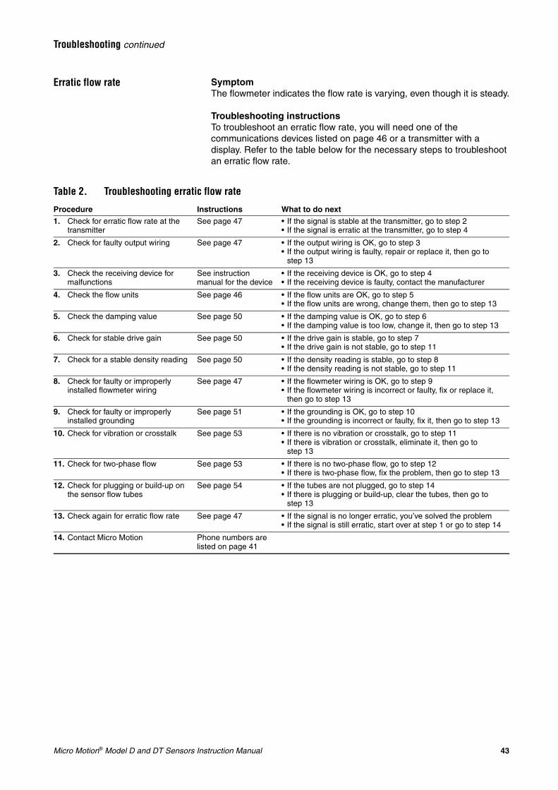
Erratic flow rate SymptomThe flowmeter indicates the flow rate is varying, even though it is steady.
Troubleshooting instructionsTo troubleshoot an erratic flow rate, you will need one of the communications devices listed on page 46 or a transmitter with a display. Refer to the table below for the necessary steps to troubleshoot an erratic flow rate.
Table 2. Troubleshooting erratic flow rate
Procedure Instructions What to do next1. Check for erratic flow rate at the
transmitterSee page 47 • If the signal is stable at the transmitter, go to step 2
• If the signal is erratic at the transmitter, go to step 4
2. Check for faulty output wiring See page 47 • If the output wiring is OK, go to step 3• If the output wiring is faulty, repair or replace it, then go to
step 13
3. Check the receiving device for malfunctions
See instruction manual for the device
• If the receiving device is OK, go to step 4• If the receiving device is faulty, contact the manufacturer
4. Check the flow units See page 46 • If the flow units are OK, go to step 5• If the flow units are wrong, change them, then go to step 13
5. Check the damping value See page 50 • If the damping value is OK, go to step 6• If the damping value is too low, change it, then go to step 13
6. Check for stable drive gain See page 50 • If the drive gain is stable, go to step 7• If the drive gain is not stable, go to step 11
7. Check for a stable density reading See page 50 • If the density reading is stable, go to step 8• If the density reading is not stable, go to step 11
8. Check for faulty or improperly installed flowmeter wiring
See page 47 • If the flowmeter wiring is OK, go to step 9• If the flowmeter wiring is incorrect or faulty, fix or replace it,
then go to step 13
9. Check for faulty or improperly installed grounding
See page 51 • If the grounding is OK, go to step 10• If the grounding is incorrect or faulty, fix it, then go to step 13
10. Check for vibration or crosstalk See page 53 • If there is no vibration or crosstalk, go to step 11• If there is vibration or crosstalk, eliminate it, then go to
step 13
11. Check for two-phase flow See page 53 • If there is no two-phase flow, go to step 12• If there is two-phase flow, fix the problem, then go to step 13
12. Check for plugging or build-up on the sensor flow tubes
See page 54 • If the tubes are not plugged, go to step 14• If there is plugging or build-up, clear the tubes, then go to
step 13
13. Check again for erratic flow rate See page 47 • If the signal is no longer erratic, you’ve solved the problem• If the signal is still erratic, start over at step 1 or go to step 14
14. Contact Micro Motion Phone numbers are listed on page 41
44 Micro Motion® Model D and DT Sensors Instruction Manual
Troubleshooting continued
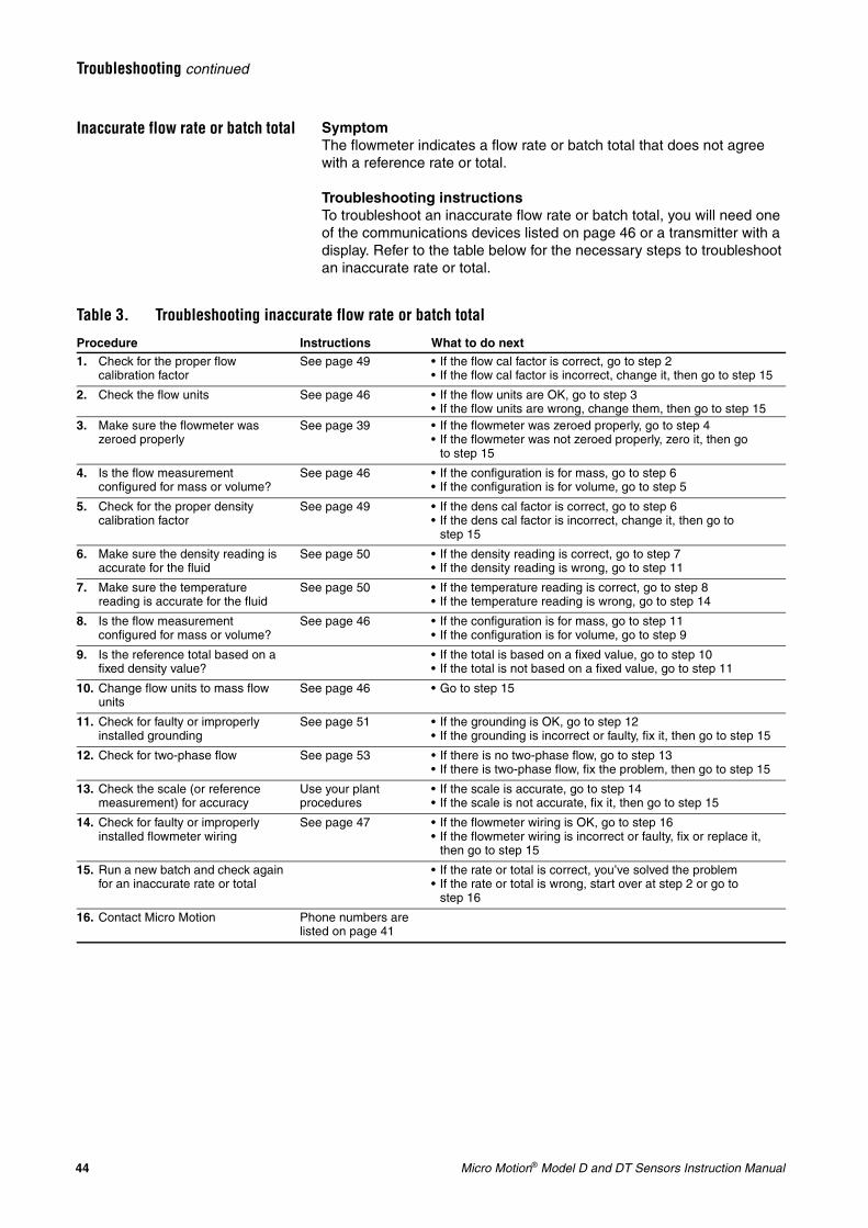
Inaccurate flow rate or batch total SymptomThe flowmeter indicates a flow rate or batch total that does not agree with a reference rate or total.
Troubleshooting instructionsTo troubleshoot an inaccurate flow rate or batch total, you will need one of the communications devices listed on page 46 or a transmitter with a display. Refer to the table below for the necessary steps to troubleshoot an inaccurate rate or total.
Table 3. Troubleshooting inaccurate flow rate or batch total
Procedure Instructions What to do next1. Check for the proper flow
calibration factorSee page 49 • If the flow cal factor is correct, go to step 2
• If the flow cal factor is incorrect, change it, then go to step 15
2. Check the flow units See page 46 • If the flow units are OK, go to step 3• If the flow units are wrong, change them, then go to step 15
3. Make sure the flowmeter was zeroed properly
See page 39 • If the flowmeter was zeroed properly, go to step 4• If the flowmeter was not zeroed properly, zero it, then go
to step 15
4. Is the flow measurement configured for mass or volume?
See page 46 • If the configuration is for mass, go to step 6• If the configuration is for volume, go to step 5
5. Check for the proper density calibration factor
See page 49 • If the dens cal factor is correct, go to step 6• If the dens cal factor is incorrect, change it, then go to
step 15
6. Make sure the density reading is accurate for the fluid
See page 50 • If the density reading is correct, go to step 7• If the density reading is wrong, go to step 11
7. Make sure the temperature reading is accurate for the fluid
See page 50 • If the temperature reading is correct, go to step 8• If the temperature reading is wrong, go to step 14
8. Is the flow measurement configured for mass or volume?
See page 46 • If the configuration is for mass, go to step 11• If the configuration is for volume, go to step 9
9. Is the reference total based on a fixed density value?
• If the total is based on a fixed value, go to step 10• If the total is not based on a fixed value, go to step 11
10. Change flow units to mass flow units
See page 46 • Go to step 15
11. Check for faulty or improperly installed grounding
See page 51 • If the grounding is OK, go to step 12• If the grounding is incorrect or faulty, fix it, then go to step 15
12. Check for two-phase flow See page 53 • If there is no two-phase flow, go to step 13• If there is two-phase flow, fix the problem, then go to step 15
13. Check the scale (or reference measurement) for accuracy
Use your plant procedures
• If the scale is accurate, go to step 14• If the scale is not accurate, fix it, then go to step 15
14. Check for faulty or improperly installed flowmeter wiring
See page 47 • If the flowmeter wiring is OK, go to step 16• If the flowmeter wiring is incorrect or faulty, fix or replace it,
then go to step 15
15. Run a new batch and check again for an inaccurate rate or total
• If the rate or total is correct, you’ve solved the problem• If the rate or total is wrong, start over at step 2 or go to
step 16
16. Contact Micro Motion Phone numbers are listed on page 41
Micro Motion® Model D and DT Sensors Instruction Manual 45
Troubleshooting continued
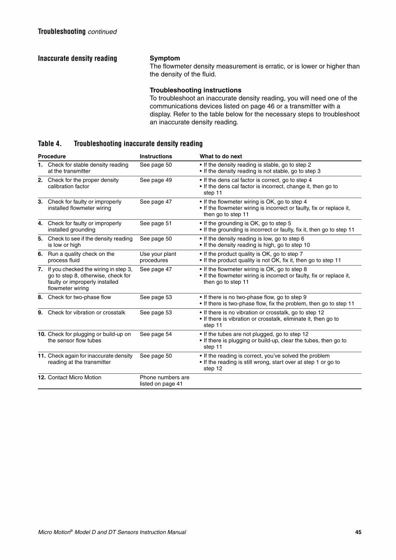
Inaccurate density reading SymptomThe flowmeter density measurement is erratic, or is lower or higher than the density of the fluid.
Troubleshooting instructionsTo troubleshoot an inaccurate density reading, you will need one of the communications devices listed on page 46 or a transmitter with a display. Refer to the table below for the necessary steps to troubleshoot an inaccurate density reading.
Table 4. Troubleshooting inaccurate density reading
Procedure Instructions What to do next1. Check for stable density reading
at the transmitterSee page 50 • If the density reading is stable, go to step 2
• If the density reading is not stable, go to step 3
2. Check for the proper density calibration factor
See page 49 • If the dens cal factor is correct, go to step 4• If the dens cal factor is incorrect, change it, then go to
step 11
3. Check for faulty or improperly installed flowmeter wiring
See page 47 • If the flowmeter wiring is OK, go to step 4• If the flowmeter wiring is incorrect or faulty, fix or replace it,
then go to step 11
4. Check for faulty or improperly installed grounding
See page 51 • If the grounding is OK, go to step 5• If the grounding is incorrect or faulty, fix it, then go to step 11
5. Check to see if the density reading is low or high
See page 50 • If the density reading is low, go to step 6• If the density reading is high, go to step 10
6. Run a quality check on the process fluid
Use your plant procedures
• If the product quality is OK, go to step 7• If the product quality is not OK, fix it, then go to step 11
7. If you checked the wiring in step 3, go to step 8, otherwise, check for faulty or improperly installed flowmeter wiring
See page 47 • If the flowmeter wiring is OK, go to step 8• If the flowmeter wiring is incorrect or faulty, fix or replace it,
then go to step 11
8. Check for two-phase flow See page 53 • If there is no two-phase flow, go to step 9• If there is two-phase flow, fix the problem, then go to step 11
9. Check for vibration or crosstalk See page 53 • If there is no vibration or crosstalk, go to step 12• If there is vibration or crosstalk, eliminate it, then go to
step 11
10. Check for plugging or build-up on the sensor flow tubes
See page 54 • If the tubes are not plugged, go to step 12• If there is plugging or build-up, clear the tubes, then go to
step 11
11. Check again for inaccurate density reading at the transmitter
See page 50 • If the reading is correct, you’ve solved the problem• If the reading is still wrong, start over at step 1 or go to
step 12
12. Contact Micro Motion Phone numbers are listed on page 41
46 Micro Motion® Model D and DT Sensors Instruction Manual
Troubleshooting continued
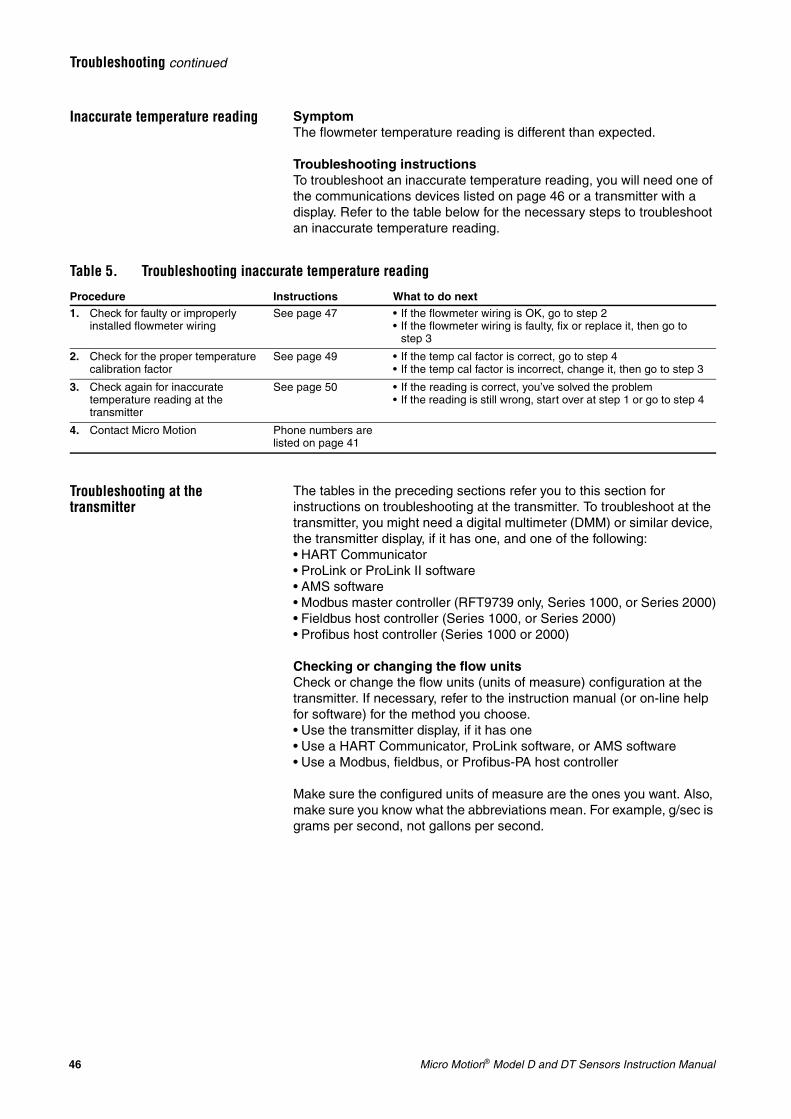
Inaccurate temperature reading SymptomThe flowmeter temperature reading is different than expected.
Troubleshooting instructionsTo troubleshoot an inaccurate temperature reading, you will need one of the communications devices listed on page 46 or a transmitter with a display. Refer to the table below for the necessary steps to troubleshoot an inaccurate temperature reading.
Troubleshooting at the transmitter
The tables in the preceding sections refer you to this section for instructions on troubleshooting at the transmitter. To troubleshoot at the transmitter, you might need a digital multimeter (DMM) or similar device, the transmitter display, if it has one, and one of the following:• HART Communicator• ProLink or ProLink II software• AMS software• Modbus master controller (RFT9739 only, Series 1000, or Series 2000)• Fieldbus host controller (Series 1000, or Series 2000)• Profibus host controller (Series 1000 or 2000)
Checking or changing the flow unitsCheck or change the flow units (units of measure) configuration at the transmitter. If necessary, refer to the instruction manual (or on-line help for software) for the method you choose.• Use the transmitter display, if it has one• Use a HART Communicator, ProLink software, or AMS software• Use a Modbus, fieldbus, or Profibus-PA host controller
Make sure the configured units of measure are the ones you want. Also, make sure you know what the abbreviations mean. For example, g/sec is grams per second, not gallons per second.
Table 5. Troubleshooting inaccurate temperature reading
Procedure Instructions What to do next1. Check for faulty or improperly
installed flowmeter wiringSee page 47 • If the flowmeter wiring is OK, go to step 2
• If the flowmeter wiring is faulty, fix or replace it, then go to step 3
2. Check for the proper temperature calibration factor
See page 49 • If the temp cal factor is correct, go to step 4• If the temp cal factor is incorrect, change it, then go to step 3
3. Check again for inaccurate temperature reading at the transmitter
See page 50 • If the reading is correct, you’ve solved the problem• If the reading is still wrong, start over at step 1 or go to step 4
4. Contact Micro Motion Phone numbers are listed on page 41
Micro Motion® Model D and DT Sensors Instruction Manual 47
Troubleshooting continued
Checking for erratic flow rate at the transmitterBefore troubleshooting erratic flow rate, you must first determine whether it is a result of the transmitter or a connected output device. Check for an erratic flow signal at the transmitter using any of the following methods. If necessary, refer to the instruction manual (or on-line help for software) for the method you choose.• Use the transmitter display, if it has one• Use a HART Communicator, ProLink software, or AMS software• Use a Modbus, fieldbus, or Profibus-PA host controller• Use a DMM on the transmitter’s 4-20 mA or frequency output terminals
If the flow rate or output signal is not erratic at the transmitter outputs, the problem is not with the transmitter.
Checking for faulty output wiringHaving already checked the output at the transmitter end (above), use a DMM to check the signal at the other end (the receiving end) of the output wiring. If the signal is not erratic, the problem is not with the output wiring.
Checking for faulty flowmeter wiringWiring problems are often incorrectly diagnosed as a faulty sensor. Examine wiring between the sensor and transmitter as follows:
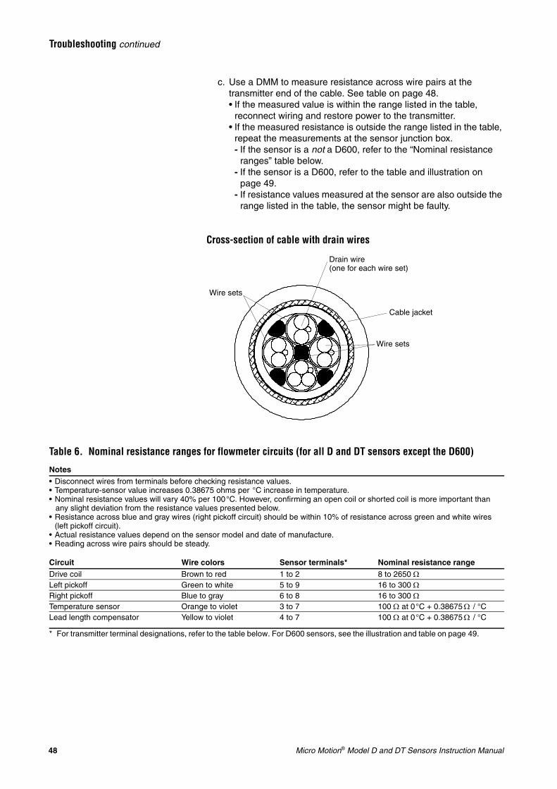
1. Check the cable preparation. The flowmeter cable must be prepared correctly. The most common problem is improperly prepared drain wires. See illustration, below. The drains are clipped at the sensor end. They should not be connected to any terminals in the sensor junction box. See wiring diagrams, pages 22-32.
2. Check wire terminations. Check to be sure wires are secured tightly in the terminal blocks, and making good connections. Make sure no wires remain exposed at either end of the flowmeter cable.
3. Check ohm levels. If the cable was properly prepared and terminal connections are good, check resistance across wire pairs to determine whether the flowmeter cable is faulty. The procedure is performed first at the transmitter, then at the sensor. Follow these steps:a. Disconnect the transmitter’s power supply.b. Disconnect sensor wiring from the transmitter’s flowmeter
terminals.
48 Micro Motion® Model D and DT Sensors Instruction Manual
Troubleshooting continued
c. Use a DMM to measure resistance across wire pairs at the transmitter end of the cable. See table on page 48.• If the measured value is within the range listed in the table,
reconnect wiring and restore power to the transmitter.• If the measured resistance is outside the range listed in the table,
repeat the measurements at the sensor junction box.- If the sensor is a not a D600, refer to the “Nominal resistance
ranges” table below.- If the sensor is a D600, refer to the table and illustration on
page 49.- If resistance values measured at the sensor are also outside the
range listed in the table, the sensor might be faulty.
Cross-section of cable with drain wires
Cable jacket
Wire sets
Wire sets
Drain wire (one for each wire set)
Table 6. Nominal resistance ranges for flowmeter circuits (for all D and DT sensors except the D600)
Notes• Disconnect wires from terminals before checking resistance values.• Temperature-sensor value increases 0.38675 ohms per °C increase in temperature.• Nominal resistance values will vary 40% per 100°C. However, confirming an open coil or shorted coil is more important than
any slight deviation from the resistance values presented below.• Resistance across blue and gray wires (right pickoff circuit) should be within 10% of resistance across green and white wires
(left pickoff circuit).• Actual resistance values depend on the sensor model and date of manufacture.• Reading across wire pairs should be steady.
Circuit Wire colors Sensor terminals* Nominal resistance rangeDrive coil Brown to red 1 to 2 8 to 2650 ΩLeft pickoff Green to white 5 to 9 16 to 300 ΩRight pickoff Blue to gray 6 to 8 16 to 300 ΩTemperature sensor Orange to violet 3 to 7 100 Ω at 0°C + 0.38675 Ω / °CLead length compensator Yellow to violet 4 to 7 100 Ω at 0°C + 0.38675 Ω / °C
* For transmitter terminal designations, refer to the table below. For D600 sensors, see the illustration and table on page 49.
Micro Motion® Model D and DT Sensors Instruction Manual 49
Troubleshooting continued
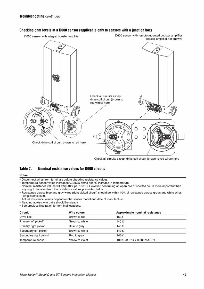
Checking ohm levels at a D600 sensor (applicable only to sensors with a junction box)
Check drive coil circuit, brown to red here
Check all circuits except drive coil circuit (brown to red wires) here
D600 sensor with integral booster amplifier D600 sensor with remote mounted booster amplifier(booster amplifier not shown)
Check all circuits except drive coil circuit (brown to red wires) here
Table 7. Nominal resistance values for D600 circuits
Notes• Disconnect wires from terminals before checking resistance values.• Temperature-sensor value increases 0.38675 ohms per °C increase in temperature.• Nominal resistance values will vary 40% per 100°C. However, confirming an open coil or shorted coil is more important than
any slight deviation from the resistance values presented below.• Resistance across blue and gray wires (right pickoff circuit) should be within 10% of resistance across green and white wires
(left pickoff circuit).• Actual resistance values depend on the sensor model and date of manufacture.• Reading across wire pairs should be steady.• See previous illustration for terminal locations.
Circuit Wire colors Approximate nominal resistanceDrive coil Brown to red 16 Ω
Primary left pickoff Green to white 140 Ω
Primary right pickoff Blue to gray 140 Ω
Secondary left pickoff Brown to white 140 Ω
Secondary right pickoff Red to gray 140 Ω
Temperature sensor Yellow to violet 100 Ω at 0°C + 0.38675 Ω / °C
50 Micro Motion® Model D and DT Sensors Instruction Manual
Troubleshooting continued
Checking the calibration factorsCheck or change the flow, density, or temperature calibration factors at the transmitter. The temperature cal factor is for the RFT9739, Model 1700, Model 2700, Model 3500, and 3700 only. If necessary, refer to the instruction manual (or on-line help for software) for the method you choose.
• Use the Model 3500 or 3700 display• Use a HART Communicator, ProLink or ProLink II software, or AMS
software• Use the host controller
Enter the calibration factors that are listed on the flowmeter calibration tag. (Calibration factors are also listed on the certificate that was shipped with the meter.) If the calibration factors at the flowmeter are already correct, the problem is not with the calibration factors.
Checking the damping valueCheck or change the damping value at the transmitter. If necessary, refer to the instruction manual (or on-line help for software) for the method you choose.• Use the Model 3500 or 3700 display• Use a HART Communicator, ProLink software, or AMS software• Use the host controller
In almost all applications, the damping value should be greater than or equal to 0.8 seconds. If the damping value is already greater than or equal to 0.8 seconds, the problem is probably not with the damping value.
Damping values less than 0.8 seconds are used in very few applications. After troubleshooting is complete, if you have a question about whether your application might require a lower damping value, contact the Micro Motion Customer Service Department. Phone numbers are listed on page 41. The two most common applications affected by a damping value that is too high are:• Very short batching applications• Very short-pass proving applications
Checking the drive gainContact Micro Motion to check the drive gain. Phone numbers are listed on page 41.
If the transmitter is a Model 1700, 2700, 3500, or 3700, you can use the display to view drive gain. For more information, refer to the manual that is shipped with the transmitter.
Checking the density or temperature readingView the flowmeter density or temperature measurement in any of several ways:• Use the transmitter display, if it has one• Use a HART Communicator, ProLink or ProLink II software, or AMS
software• Use the connected output device, if there is one
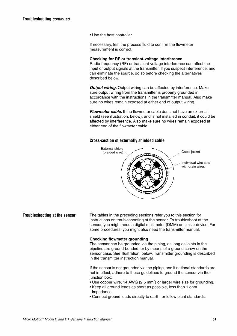
Micro Motion® Model D and DT Sensors Instruction Manual 51
Troubleshooting continued
• Use the host controller
If necessary, test the process fluid to confirm the flowmeter measurement is correct.
Checking for RF or transient-voltage interferenceRadio-frequency (RF) or transient-voltage interference can affect the input or output signals at the transmitter. If you suspect interference, and can eliminate the source, do so before checking the alternatives described below.
Output wiring. Output wiring can be affected by interference. Make sure output wiring from the transmitter is properly grounded in accordance with the instructions in the transmitter manual. Also make sure no wires remain exposed at either end of output wiring.
Flowmeter cable. If the flowmeter cable does not have an external shield (see illustration, below), and is not installed in conduit, it could be affected by interference. Also make sure no wires remain exposed at either end of the flowmeter cable.
Cross-section of externally shielded cable
Troubleshooting at the sensor The tables in the preceding sections refer you to this section for instructions on troubleshooting at the sensor. To troubleshoot at the sensor, you might need a digital multimeter (DMM) or similar device. For some procedures, you might also need the transmitter manual.
Checking flowmeter groundingThe sensor can be grounded via the piping, as long as joints in the pipeline are ground-bonded, or by means of a ground screw on the sensor case. See illustration, below. Transmitter grounding is described in the transmitter instruction manual.
If the sensor is not grounded via the piping, and if national standards are not in effect, adhere to these guidelines to ground the sensor via the junction box:• Use copper wire, 14 AWG (2,5 mm2) or larger wire size for grounding.• Keep all ground leads as short as possible, less than 1 ohm
impedance.• Connect ground leads directly to earth, or follow plant standards.
External shield(braided wire) Cable jacket
Individual wire sets with drain wires
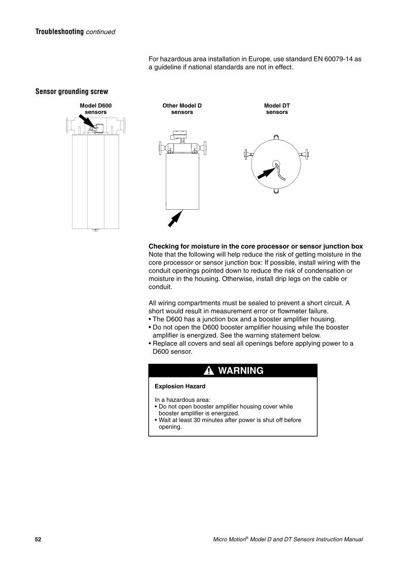
52 Micro Motion® Model D and DT Sensors Instruction Manual
Troubleshooting continued
For hazardous area installation in Europe, use standard EN 60079-14 as a guideline if national standards are not in effect.
Sensor grounding screw
Checking for moisture in the core processor or sensor junction boxNote that the following will help reduce the risk of getting moisture in the core processor or sensor junction box: If possible, install wiring with the conduit openings pointed down to reduce the risk of condensation or moisture in the housing. Otherwise, install drip legs on the cable or conduit.
All wiring compartments must be sealed to prevent a short circuit. A short would result in measurement error or flowmeter failure.• The D600 has a junction box and a booster amplifier housing.• Do not open the D600 booster amplifier housing while the booster
amplifier is energized. See the warning statement below.• Replace all covers and seal all openings before applying power to a
D600 sensor.
Other Model D sensors
Model DT sensors
Model D600 sensors
WARNING
Explosion Hazard
In a hazardous area:• Do not open booster amplifier housing cover while
booster amplifier is energized.• Wait at least 30 minutes after power is shut off before
opening.
Micro Motion® Model D and DT Sensors Instruction Manual 53
Troubleshooting continued
Open the junction box (and, for a D600, the booster amplifier housing) to check for moisture. If moisture is present, dry out the junction box. Do not use contact cleaner. Follow these guidelines to avoid risk of condensation or excessive moisture from accumulating:• Seal all conduit openings.• Install drip legs in conduit or cable.• If possible, install wiring with junction-box openings pointed down.• Check integrity of gaskets.• Close and fully seal all housing covers.
Checking for mounting stress on the sensorBecause each installation is unique, it is not possible to offer a definitive solution for mounting problems. However, mounting stresses can be caused by one or more of the following conditions:• The pipeline is being supported by (hung from) the sensor.• Misaligned piping was drawn together by the sensor.• An unsupported pipeline is not sturdy enough to support the sensor.
If you are unable to determine whether the process connections are being subjected to mounting stress, contact Micro Motion for additional assistance. Phone numbers are listed on page 41.
Checking for vibration and crosstalkMicro Motion sensors have been designed to minimize the effect of vibration. In very rare cases, however, vibration or crosstalk can affect flowmeter operation. Crosstalk is the transfer of resonant vibration from one sensor to another, and sometimes occurs when two like-size sensors are installed in close proximity to each other and are operating on the same fluid for short periods of time.
Micro Motion meters are rarely affected by vibration, so vibration or crosstalk is probably not the problem. If you are not sure whether vibration or crosstalk is affecting the sensor, contact Micro Motion for additional assistance. Phone numbers are listed on page 41.
Checking for 2-phase flowTwo-phase flow occurs when air or gas is present in a liquid process stream, or when liquid is present in a gas process stream. Two-phase flow has several causes, as described below.
Leaks. Leaks can occur at process connections, valve seals, and pump seals, resulting in air being introduced into a liquid stream. Air might also be drawn in at the system inlet. Check the system for leaks, and repair any leaks that are found.
Cavitation and flashing. Cavitation and flashing are caused by operating the system at or near the process fluid vapor pressure, resulting in pockets of air or gas being introduced into the process fluid. If the sensor is near a device that causes pressure drop, such as a control valve, locating the sensor upstream from the device can decrease the risk of flashing. Alternatively, increasing back pressure downstream from the sensor can also reduce the risk of cavitation and flashing.
Cascading. Cascading of the fluid can occur when the flow rate diminishes to the point where the sensor tube is only partially filled.
54 Micro Motion® Model D and DT Sensors Instruction Manual
Troubleshooting continued
Often, this occurs because fluid is flowing downward through a sensor installed in a vertical pipeline. (When a sensor is mounted this way, it is called the flag-mount orientation).
To help eliminate cascading, fluids should flow upward through a flag-mounted sensor. Mounting the sensor in the preferred orientation often reduces cascading. (See Orientation, page 13.) Increasing back pressure downstream from the sensor can also reduce or eliminate cascading.
High points in the system. When measuring liquids, entrained air (pockets of non-condensable gas) can collect in high points of a fluid system. If the fluid velocity is low, and/or the high points are very high relative to the system, entrained air pockets can grow and persist. If the air pocket releases and passes through the sensor, measurement error could occur. One possible solution is to install vent valves or air eliminators at a high point in the system, upstream from the sensor. Use your common plant practices if you choose to install vent valves or air eliminators.
Low points in the system. When measuring gases, liquid condensate can collect in low points of a fluid system. If the fluid velocity is low, and/or the low points are very low relative to the system, condensates can accumulate and persist. If the liquid passes through the sensor, measurement error could occur. One possible solution is to install condensate valves at a low point in the system, upstream from the sensor. Use your common plant practices if you choose to install condensate valves.
Checking for plugging or build-upIf the process fluid tends to build up in the piping, the sensor can become plugged or partially plugged due to build-up of material inside the sensor flow tubes. To determine whether plugging or build-up has occurred, check at the transmitter for a high drive gain and high density reading (see page 50).• If the drive gain and the density reading are both high, flush or clean
the sensor, then check for an accurate density reading on water (or some other fluid with a known density). If the density is still wrong, plugging of the tube is probably not the problem.
• If either the drive gain or the density reading is not high, plugging of the tube is probably not the problem.
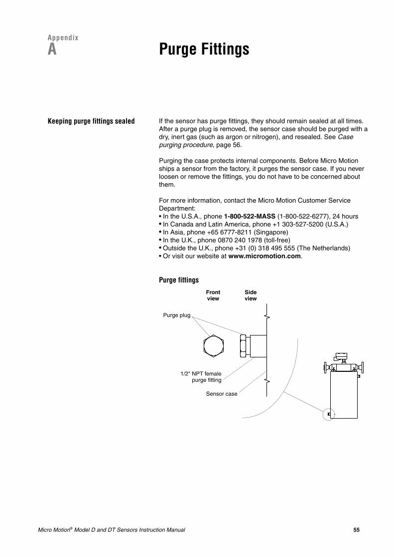
Micro Motion® Model D and DT Sensors Instruction Manual 55
Appendix
A Purge Fittings
Keeping purge fittings sealed If the sensor has purge fittings, they should remain sealed at all times. After a purge plug is removed, the sensor case should be purged with a dry, inert gas (such as argon or nitrogen), and resealed. See Case purging procedure, page 56.
Purging the case protects internal components. Before Micro Motion ships a sensor from the factory, it purges the sensor case. If you never loosen or remove the fittings, you do not have to be concerned about them.
For more information, contact the Micro Motion Customer Service Department:• In the U.S.A., phone 1-800-522-MASS (1-800-522-6277), 24 hours• In Canada and Latin America, phone +1 303-527-5200 (U.S.A.)• In Asia, phone +65 6777-8211 (Singapore)• In the U.K., phone 0870 240 1978 (toll-free)• Outside the U.K., phone +31 (0) 318 495 555 (The Netherlands)• Or visit our website at www.micromotion.com.
Purge fittings
1/2" NPT femalepurge fitting
Purge plug
Sensor case
Front view
Side view
56 Micro Motion® Model D and DT Sensors Instruction Manual
Purge Fittings continued
Using purge fittings The primary reason for having purge fittings is to monitor pressure inside the sensor case. Some users, such as those measuring highly volatile fluids, install a pressure transmitter across the sensor purge fittings. A control device, connected to the pressure transmitter, shuts down the process if a change in pressure is detected. This provides additional protection should a rupture occur inside the sensor.
Removing a purge plug If you remove a purge plug from the sensor case, it is necessary to re-purge the case.
Case purging procedure Read all instructions before performing the case purging procedure. It is not necessary to perform this procedure unless a purge plug has been removed.
1. Shut down the process, or set control devices for manual operation.
2. Remove both purge plugs from the sensor case. If purge lines are being used, open the valve in the purge lines.
WARNING
Removing a purge plug will require the sensor case to be re-purged with a dry inert gas. Improper pressurization could result in serious personal injury.
Follow all instructions for re-purging the sensor case. See Case purging procedure, below.
CAUTION
Performing the purge procedure while the flowmeter is operating could affect measurement accuracy, resulting in inaccurate flow signals.
Before performing the case purging procedure, shut down the process, or set control devices for manual operation.
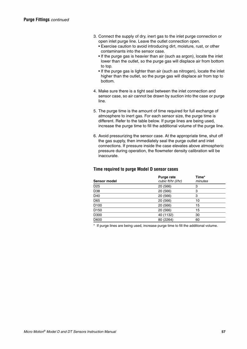
Micro Motion® Model D and DT Sensors Instruction Manual 57
Purge Fittings continued
3. Connect the supply of dry, inert gas to the inlet purge connection or open inlet purge line. Leave the outlet connection open.• Exercise caution to avoid introducing dirt, moisture, rust, or other
contaminants into the sensor case.• If the purge gas is heavier than air (such as argon), locate the inlet
lower than the outlet, so the purge gas will displace air from bottom to top.
• If the purge gas is lighter than air (such as nitrogen), locate the inlet higher than the outlet, so the purge gas will displace air from top to bottom.
4. Make sure there is a tight seal between the inlet connection and sensor case, so air cannot be drawn by suction into the case or purge line.
5. The purge time is the amount of time required for full exchange of atmosphere to inert gas. For each sensor size, the purge time is different. Refer to the table below. If purge lines are being used, increase the purge time to fill the additional volume of the purge line.
6. Avoid pressurizing the sensor case. At the appropriate time, shut off the gas supply, then immediately seal the purge outlet and inlet connections. If pressure inside the case elevates above atmospheric pressure during operation, the flowmeter density calibration will be inaccurate.
Time required to purge Model D sensor cases
Sensor modelPurge ratecubic ft/hr (l/hr)
Time*minutes
* If purge lines are being used, increase purge time to fill the additional volume.
D25 20 (566) 3D38 20 (566) 3D40 20 (566) 3D65 20 (566) 10D100 20 (566) 15D150 20 (566) 15D300 40 (1132) 30D600 80 (2264) 60

58 Micro Motion® Model D and DT Sensors Instruction Manual
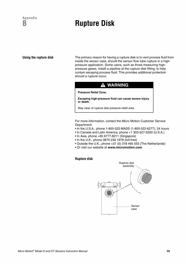
Micro Motion® Model D and DT Sensors Instruction Manual 59
Appendix
B Rupture Disk
Using the rupture disk The primary reason for having a rupture disk is to vent process fluid from inside the sensor case, should the sensor flow tube rupture in a high-pressure application. Some users, such as those measuring high-pressure gases, install a pipeline at the rupture disk fitting, to help contain escaping process fluid. This provides additional protection should a rupture occur.
For more information, contact the Micro Motion Customer Service Department:• In the U.S.A., phone 1-800-522-MASS (1-800-522-6277), 24 hours• In Canada and Latin America, phone +1 303-527-5200 (U.S.A.)• In Asia, phone +65 6777-8211 (Singapore)• In the U.K., phone 0870 240 1978 (toll-free)• Outside the U.K., phone +31 (0) 318 495 555 (The Netherlands)• Or visit our website at www.micromotion.com.
Rupture disk
WARNING
Pressure Relief Zone.
Escaping high-pressure fluid can cause severe injury or death.
Stay clear of rupture disk pressure-relief area.
Rupture diskassembly
Sensor case

60 Micro Motion® Model D and DT Sensors Instruction Manual
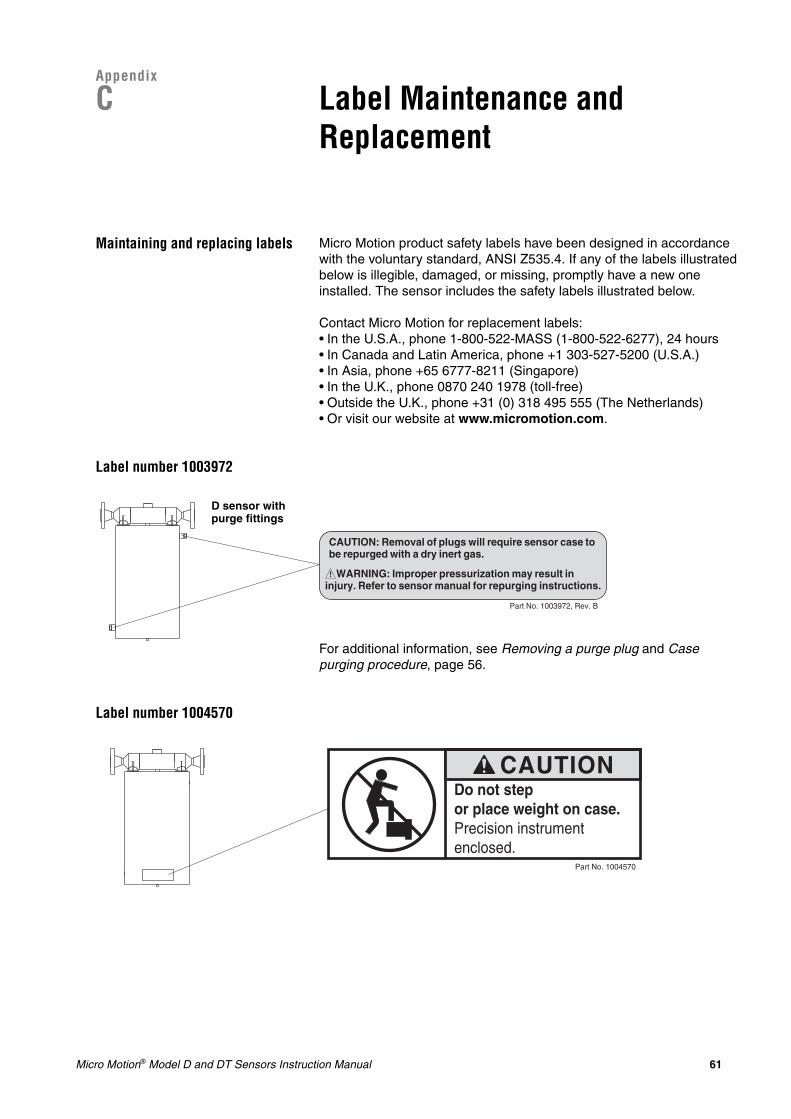
Micro Motion® Model D and DT Sensors Instruction Manual 61
Appendix
C Label Maintenance and Replacement
Maintaining and replacing labels Micro Motion product safety labels have been designed in accordance with the voluntary standard, ANSI Z535.4. If any of the labels illustrated below is illegible, damaged, or missing, promptly have a new one installed. The sensor includes the safety labels illustrated below.
Contact Micro Motion for replacement labels:• In the U.S.A., phone 1-800-522-MASS (1-800-522-6277), 24 hours• In Canada and Latin America, phone +1 303-527-5200 (U.S.A.)• In Asia, phone +65 6777-8211 (Singapore)• In the U.K., phone 0870 240 1978 (toll-free)• Outside the U.K., phone +31 (0) 318 495 555 (The Netherlands)• Or visit our website at www.micromotion.com.
Label number 1003972
For additional information, see Removing a purge plug and Case purging procedure, page 56.
Label number 1004570
CAUTION: Removal of plugs will require sensor case tobe repurged with a dry inert gas.
! WARNING: Improper pressurization may result ininjury. Refer to sensor manual for repurging instructions.
Part No. 1003972, Rev. B
D sensor with purge fittings
Part No. 1004570
CAUTIONDo not stepor place weight on case.Precision instrumentenclosed.
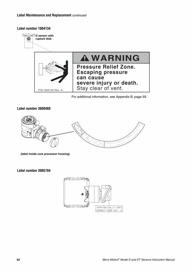
62 Micro Motion® Model D and DT Sensors Instruction Manual
Label Maintenance and Replacement continued
Label number 1004134
For additional information, see Appendix B, page 59.
Label number 3600460
Label number 3005784
P/N 1004134 Rev. A
WARNINGPressure Relief Zone.Escaping pressurecan cause severe injury or death.Stay clear of vent.
D sensor with rupture disk
(label inside core processor housing)
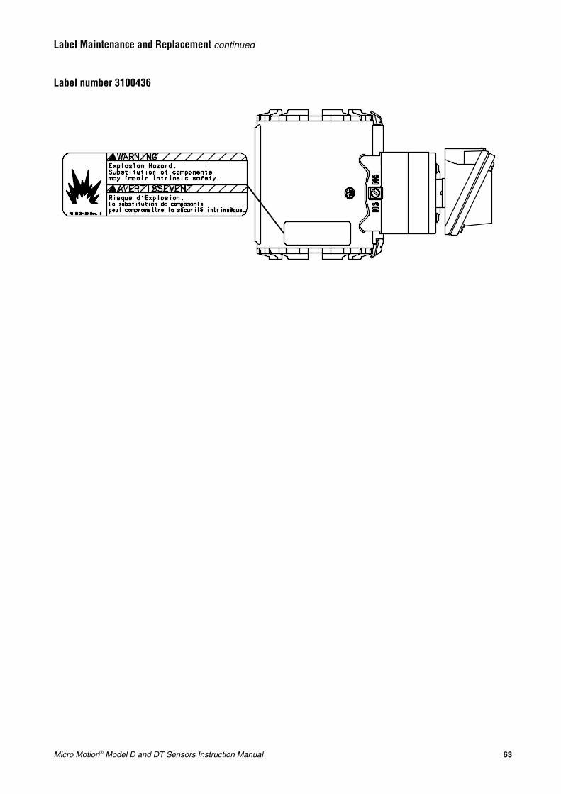
Micro Motion® Model D and DT Sensors Instruction Manual 63
Label Maintenance and Replacement continued
Label number 3100436

64 Micro Motion® Model D and DT Sensors Instruction Manual
Micro Motion® Model D and DT Sensors Instruction Manual 65
Appendix
D Return Policy
General guidelines Micro Motion procedures must be followed when returning equipment. These procedures ensure legal compliance with government transportation agencies and help provide a safe working environment for Micro Motion employees. Failure to follow Micro Motion procedures will result in your equipment being refused delivery.
Information on return procedures and forms is available on our web support system at www.micromotion.com, or by phoning the Micro Motion Customer Service department.
New and unused equipment Only equipment that has not been removed from the original shipping package will be considered new and unused. New and unused equipment requires a completed Return Materials Authorization form.
Used equipment All equipment that is not classified as new and unused is considered used. This equipment must be completely decontaminated and cleaned before being returned.
Used equipment must be accompanied by a completed Return Materials Authorization form and a Decontamination Statement for all process fluids that have been in contact with the equipment. If a Decontamination Statement cannot be completed (e.g., for food-grade process fluids), you must include a statement certifying decontamination and documenting all foreign substances that have come in contact with the equipment.

66 Micro Motion® Model D and DT Sensors Instruction Manual
Micro Motion® Model D and DT Sensors Instruction Manual 67
A
Air eliminators 54AMS software 41, 46Approvals tag
keys for sensor location 9
B
Batch totalinaccurate batch total 44
Before you begin 1–7additional information 7installation process 6your new sensor 1
Booster amplifiersensor location 10
C
Cable. See also Flowmeter cable; WiringDT sensor 10glands 29
Calibrationcertificate 50startup 39troubleshooting 49
Cascading 53Cavitation 53Certificate of conformance 50Characterization 39Condensate valves 54Configuration 39Coriolis flowmeter 1Crosstalk 53Customer service 40
D
Damping 50Density
checking 50inaccurate density reading 45
DMM 41, 46Drive gain 50
E
Entrained air or gas 53–54European installations 2
F
Fieldbus host 46Flashing 53Flow direction 13Flow direction arrow
sensor orientation 13Flow rate
erratic flow rate 43inaccurate flow rate 44
Flowmetercable
. See also WiringRF interference 51troubleshooting 47–49
components of 1grounding 28
troubleshooting 51startup 39zeroing 39
G
Groundingtroubleshooting 51wiring 28
H
HART Communicatortroubleshooting with 46
Hazardous area installationssensor location 11wiring 19
I
Installationstep 2: orientation 13step 3: mounting 17step 4: wiring 19, 22–36step 5: startup 39
Installation process 6
J
Junction boxtroubleshooting 52
K
Keys for installationsensor location 9sensor mounting 17sensor orientation 13
L
Labels 61Location
booster amplifier 10D600 10DT sensor junction box 10hazardous area installations 11keys for installation 9pipe run 9
M
Modbustroubleshooting with 46
Mounting 17D600 optional mounting 18DT sensors 18keys for installation 17
O
Index
68 Micro Motion® Model D and DT Sensors Instruction Manual
Index continued
Orientation 13flow direction 13flow direction arrow 13keys for installation 13process fluids 13vertical pipeline 13
P
Pipe run 9Plugging 54Process fluid
flow direction 13sensor orientation 13
ProLink software 41, 46Purge fittings
instructions 55–57
R
Resistance ranges for flowmeter circuits 48–49Return policy 65RF interference 51Rupture disk 59
S
Sensorbooster amplifier
location 10components 2–6grounding 28labels 61mounting 17orientation 13purge fittings 55–57rupture disk 59startup 39troubleshooting 41wiring 19, 22–32, 36
Startup 39configuration, calibration, and characterization 39customer service 40zeroing 39
T
Temperaturechecking 50inaccurate temperature reading 46
Transmittercompatible models 1
Troubleshooting 41air eliminators 54AMS software 41, 46at the sensor 51at the transmitter 46–51cascading 53cavitation 53
checkingcalibration factors 49crosstalk 53damping value 50density reading 50drive gain 50faulty flowmeter wiring 47–49faulty output wiring 47grounding 51junction box 52mounting stress 53plugging 54RF interference 51temperature reading 502-phase flow 53vibration 53
condensate valves 54customer service 41DMM 41, 46Fieldbus host 46flashing 53general information 41HART Communicator 46high points in system 54low points in system 54procedures
erratic flow rate 43inaccurate batch total 44inaccurate density reading 45inaccurate flow rate 44inaccurate temperature reading 46zero drift 42
ProLink software 41, 46RF interference 51vent valves 54wiring
resistance ranges 48–49
V
Vent valves 54
W
Wiring 19, 22–36connections to transmitter 21–24, 29–32D600 sensor 24grounding 28hazardous area installations 19transmitter
1700 or 2700 to Model D or DT sensor 24troubleshooting 47–49
grounding 51output wiring 51RF interference 51
Z
Zero drift 42Zeroing
flowmeter startup 39keys for sensor location 9

Micro Motion Inc. USAWorldwide Headquarters7070 Winchester CircleBoulder, Colorado 80301T +1 303-527-5200
+1 800-522-6277F +1 303-530-8459
Micro Motion EuropeEmerson Process ManagementNeonstraat 16718 WX EdeThe NetherlandsT +31 (0) 318 495 555F +31 (0) 318 495 556
Micro Motion JapanEmerson Process Management1-2-5, Higashi ShinagawaShinagawa-kuTokyo 140-0002 JapanT +81 3 5769-6803F +81 3 5769-6844
Micro Motion AsiaEmerson Process Management1 Pandan CrescentSingapore 128461Republic of SingaporeT +65 6777-8211F +65 6770-8003
Micro Motion United KingdomEmerson Process Management LimitedHorsfield WayBredbury Industrial EstateStockport SK6 2SU U.K.T +44 0870 240 1978F +44 0800 966 181
©2008, Micro Motion, Inc. All rights reserved. P/N 1005172, Rev. C
*1005172*
For the latest Micro Motion product specifications, view the PRODUCTS section of our web site at www.micromotion.com