Embed Size (px)
Citation preview

Model CP65
Cinema Processor
Installation and Alignment
InstructionsIssue 4 Part No. 91234
Model CP65 Cinema Processor Installation and Alignment Instructions
Dolby Laboratories Inc
U.S. HeadquartersDolby Laboratories Inc100 Potrero AvenueSan Francisco, CA 94103-4813Telephone 415-558-0200Facsimile 41-863-1373www.dolby.com
U.K. European OfficeDolby Laboratories IncWootton BassettWiltshire SN4 8QJ EnglandTelephone (44) 1793-842100Facsimile (44) 1793-842101
DISCLAIMER OF WARRANTIES: Equipment manufactured by Dolby Laboratories is warranted against defects in materials andworkmanship for a period of one year from the date of purchase. All warranties, conditions or other terms implied by statute ar excluded to thefullest extent allowed by law.
LIMITATION OF LIABILITY: It is understood and agreed that Dolby Laboratories’ liability whether in contract, in tort, under any warranty, innegligence or otherwise shall not exceed the cost of repair or replacement of the defective components and under no circumstances shall DolbyLaboratories be liable for incidental, special, direct, indirect or consequential damages (including but not limited to damage to software orrecorded audio or visual material), or loss of use, revenue or profit even if Dolby Laboratories or its agents have been advised, orally or inwriting, of the possibility of such damages.
Dolby and the double-D symbol are registered trademarks of Dolby Laboratories.
©1999 Dolby Laboratories Inc
ii
Issue 4S99/9563/12772
Part No. 91234
Model CP65 Cinema Processor Installation and Alignment Instructions
iii
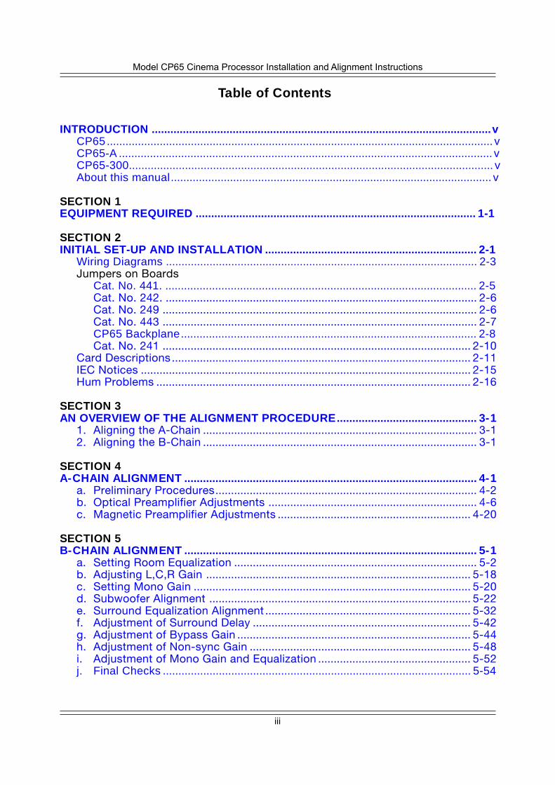
Table of Contents
INTRODUCTION .............................................................................................................vCP65............................................................................................................................ vCP65-A ........................................................................................................................ vCP65-300..................................................................................................................... vAbout this manual....................................................................................................... v
SECTION 1EQUIPMENT REQUIRED .......................................................................................... 1-1
SECTION 2INITIAL SET-UP AND INSTALLATION .................................................................... 2-1
Wiring Diagrams .................................................................................................... 2-3Jumpers on Boards
Cat. No. 441. .................................................................................................... 2-5Cat. No. 242. .................................................................................................... 2-6Cat. No. 249 ..................................................................................................... 2-6Cat. No. 443 ..................................................................................................... 2-7CP65 Backplane............................................................................................... 2-8Cat. No. 241 ................................................................................................... 2-10
Card Descriptions ................................................................................................ 2-11IEC Notices .......................................................................................................... 2-15Hum Problems ..................................................................................................... 2-16
SECTION 3AN OVERVIEW OF THE ALIGNMENT PROCEDURE............................................. 3-1
1. Aligning the A-Chain ........................................................................................ 3-12. Aligning the B-Chain ........................................................................................ 3-1
SECTION 4A-CHAIN ALIGNMENT .............................................................................................. 4-1
a. Preliminary Procedures.................................................................................... 4-2b. Optical Preamplifier Adjustments ................................................................... 4-6c. Magnetic Preamplifier Adjustments .............................................................. 4-20
SECTION 5B-CHAIN ALIGNMENT .............................................................................................. 5-1
a. Setting Room Equalization .............................................................................. 5-2b. Adjusting L,C,R Gain ..................................................................................... 5-18c. Setting Mono Gain ......................................................................................... 5-20d. Subwoofer Alignment .................................................................................... 5-22e. Surround Equalization Alignment .................................................................. 5-32f. Adjustment of Surround Delay ...................................................................... 5-42g. Adjustment of Bypass Gain ........................................................................... 5-44h. Adjustment of Non-sync Gain ....................................................................... 5-48i. Adjustment of Mono Gain and Equalization ................................................. 5-52j. Final Checks ................................................................................................... 5-54
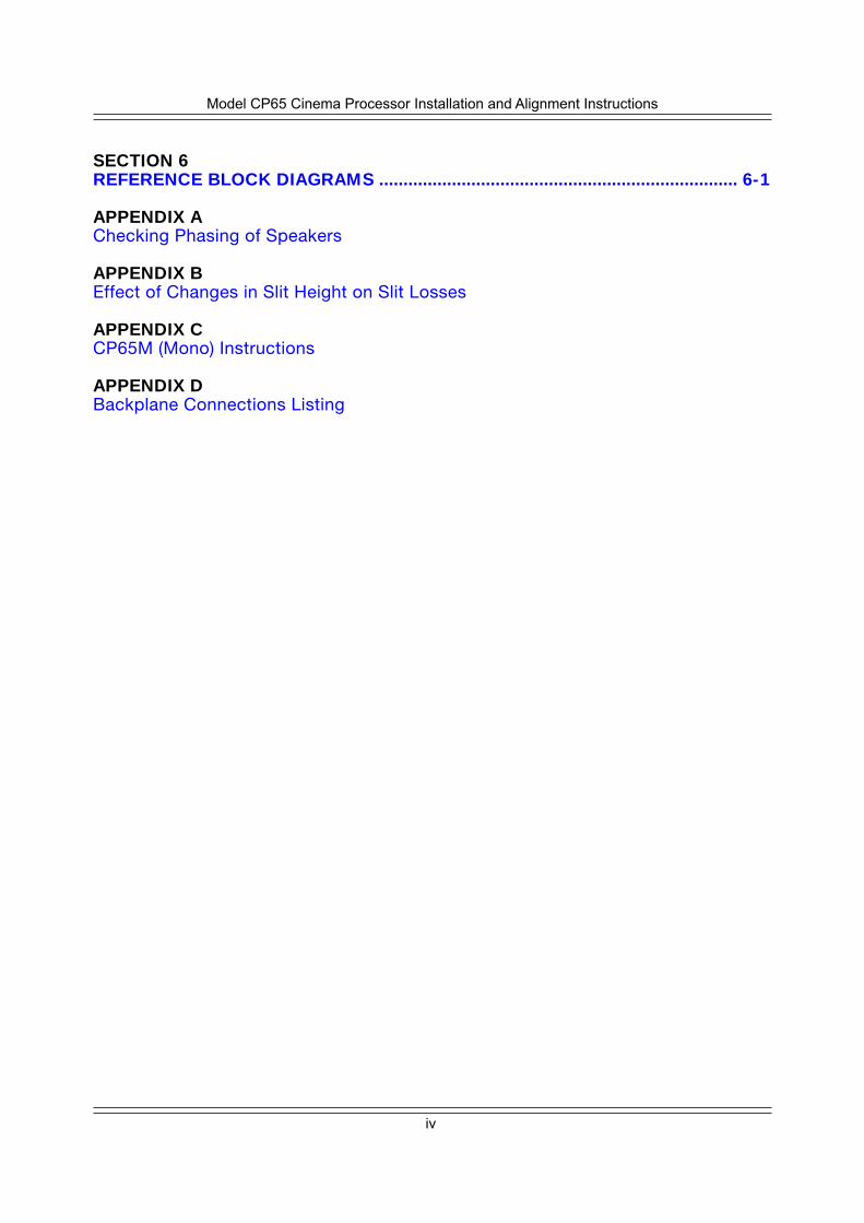
iv
Model CP65 Cinema Processor Installation and Alignment Instructions
SECTION 6REFERENCE BLOCK DIAGRAMS .......................................................................... 6-1
APPENDIX AChecking Phasing of Speakers
APPENDIX BEffect of Changes in Slit Height on Slit Losses
APPENDIX CCP65M (Mono) Instructions
APPENDIX DBackplane Connections Listing
INTRODUCTION
This manual contains essential information on the installation and alignment of the CP65Cinema Sound Processor. The CP65 supersedes the CP55 and is available in three versions:
CP65
The standard configuration, equipped for the reproduction of the followingsound formats
• 01 Mono–for all optical prints of any vintage with conventional mono optical(“Academy”) sound-tracks.
• 04 Dolby Stereo A-type
• 05 Dolby Stereo SR
• 10 Dolby Stereo Digital-with the addition of an external digital adapter
• 60 Non-sync
• Mag / Aux–This format may be programmed in a number of different ways.Possible options include:
• Magnetic sound-tracks without A-type noise reduction.
• Extra sound sources, such as a Magnetic follower/dubber, PA microphonewith preamp or a “stereo” synthesizer.
CP65-A
Equipped with A-type noise reduction only. Reproduces the same formatsas the standard CP65 with the exception of 05 Dolby Stereo SR.
CP65-300
Equipped with two Cat. No. 300 modules in place of the Cat. No. 350 SRmodules. Cat. No. 300 SR/A processors contain both A-type and SR circuitsand these additional two channels of A-type along with the channels in theCat. No. 222 modules are used to decode 70 mm Dolby Stereo magneticsoundtracks (format 42).
About this manual
This manual is intended to be used by individuals who are qualified in the area of cinemasound service. The basic day-to-day operation of the CP65 is covered in the CP65Operator’s Guide.
v
This installation and alignment manual covers the procedures necessary to ensure that thetheatre sound system is accurately aligned to standards that have been established by DolbyLaboratories. Following these procedures will ensure that the theatre sound system willaccurately reproduce the soundtrack as the director and sound mixers intended.
The Dolby Cinema Processor is the central element of the theatre sound system. Theprojector, the Dolby Processor, the power amplifiers and the loudspeakers, as well as theauditorium itself, must be considered when aligning the system for optimum performance.
The system alignment procedure is divided into two parts—the A-chain alignment whichcovers the projector, optical preamplifier, and Dolby noise reduction adjustments—and the B-chain alignment which covers the portions of the system from the room equalization circuitsto the CP65 fader through to the loudspeakers.
The alignment instructions in this Manual are presented in three columns. The first column,Action, contains a drawing of the item to be adjusted and a caption containing a briefdescription of the action to be taken. The second column, Indication, contains a visualindication of the desired results, where applicable. The third column, Notes, containsinformation which amplifies and supplements the other two columns.
If you are familiar with alignment of other Dolby Cinema Processors you need to follow onlythe information in the first two columns. If you are unfamiliar with the equipment or face specialsituations that require complete information you should consult the Notes column.
CAUTIONThis Installation Manual is for use byqualified personnel only. To avoidelectric shock do not perform anyservicing other than that contained inthe Operator's Guide unless you arequalified to do so.
vi
1-1
SECTION 1EQUIPMENT REQUIRED
a. Dual-trace oscilloscope with X-Y facilities.
b. 1/3 Octave Real Time Spectrum Analyzer (RTA) with calibrated microphone.(Preferably multiple microphones and a multiplexer should be used.)
c. Sound Pressure Level Meter (with slow time-constant and C weightingscale).
d. Cat. No. 85C pink noise generator.
e. Cat. No. 67 extender for the equalizer modules.
f. Test Films (available from Dolby Laboratories or equipment dealers). Werecommend that you make loops of these test films, sufficiently long to gothrough the entire projector film path so that azimuth and lateral filmposition adjustments can be made accurately.
(1) Dolby Tone and Pink Noise — Cat. No. 69
(2) 1kHz, 100% Modulation, Left/Right — Cat. No. 97
1-2
(3) SMPTE Buzz Track
(4) Stereo Optical Surround Level — Cat. No. 151
g. The following films can also be purchased from Dolby Laboratories or acinema equipment dealer. The films are optional items that are used in finalsystem sound verification:
(1) “Jiffy” Test Film — Cat. No. 251 (2) “Listen . . .” Film — Cat. No. 351.
JIFFYTEST FILM
CN 251–A subjective film for testing theatre sound
DOLBY STEREORunning time: 8 minutes.Picture format: 1.85:1 widescreen or 2.35:1 anamorphic.Sound format:
04stereo opticalwith surround
Dolby Laboratories, 100 Potrero Avenue,San Francisco, CA 94103-4813
Telephone 415-558-0200, Telex 34409, Facsimile 415-863-1373Dolby, the Double-D symbol and Dolby Stereo are trademarks
of Dolby Laboratories Licensing Corporation.S89/4784/8690
RECORDED IN
listen…CN 351–The Stereo Demonstration Film
DOLBY STEREORunning time: 8 minutes.Picture format: 2.35:1 anamorphic.Sound format:
04stereo opticalwith surround
Dolby Laboratories, 100 Potrero Avenue,San Francisco, CA 94103-4813
Telephone 415-558-0200, Telex 34409, Facsimile 415-863-1373Dolby, the Double-D symbol and Dolby Stereo are trademarks
of Dolby Laboratories Licensing Corporation.S89/4784/6776
RECORDED IN
2-1
SECTION 2INITIAL SET-UP AND INSTALLATION
Before you remove or replace the Cat. No. 240A Optical Pre-Amp or the Cat.No. 249 Power Supply Card, first disconnect AC power from the CP65 to protect thespeakers and the CP65 from damage. For all other modules in the CP65, first switchto BYPASS; you can then safely remove or replace the desired card withoutdisconnecting power from the CP65.
Do NOT connect the CP65 to mains power until all connections have been made and alljumpers have been installed (see STEP 9 later in this section).
STEP 1 If air-conditioning noise is audible in the theatre, arrange for lubrication ofthe motor, fan bearings, adjustment of belts and drives, and cleaning offilters to reduce the ambient noise to a minimum.
If the CP65 replaces an existing cinema sound system, play a typical filmbefore you remove the old system so you will have a benchmark forcomparison to the new system and as a check of the positioning of theexciter lamp, the focusing of the sound track lens, and the condition of thesolar cell.
Before you run the film:
• Verify that the existing power amplifiers are in good working order.• Verify that the existing speakers are in good working order, and that there
is no loose or missing hardware or structural members in the enclosures.• Verify that all wiring is present and properly connected and that crossovers
are operating and are correctly adjusted.• Check the phasing of the speaker connections (see Appendix A).• Verify that there are adequate earth (ground) connections.• Verify that radio interference problems are adequately resolved.
STEP 2 While you are running the film, listen carefully in various parts of the theatrefor audio system problems:
• Hum.• Noise, clicks, pops.• Distortion.• Poor tonal balance (lack of high-frequency or bass content).
These problems must be resolved before you can proceed to the next stepin the installation.
STEP 3 To avoid heat problems, do not locate the CP65 immediately above orbelow the power amplifiers.
Always leave a 1U (43 mm, 1.75") space above and below the CP65 toprovide adequate ventilation. Install an air guide or baffle to deflect hotair from equipment below the CP65.
2-2
Locate the power amplifiers away from the Cat. No. 240A optical preamplifierto avoid hum pickup problems.
STEP 4 Disconnect power from the existing cinema sound equipment.
STEP 5 Disconnect all cabling from the existing cinema sound processing system,but do not disconnect the wiring from power amplifiers, etc.
STEP 6 Check that the CP65 voltage selector switch is set correctly for your mainsvoltage and that the correct fuses are installed. (The selector switch islocated on the rear of the Cat. No. 259 Power Supply and can be seenthrough the backplane.)
DISCONNECT THE CP65 FROM POWER BEFORE YOU TURN THESELECTOR SWITCH FROM ONE POSITION TO ANOTHER.
The CP65 accepts both 50 Hz and 60 Hz power. The mains voltages mustfall within the following limits:
Voltage AcceptableSetting Voltage Range Fuse Type
100 VAC 85-110 VAC 1.25 A 1/4" x 1-1/4" slow-blow120 VAC 102-132 VAC 1.25 A 1/4" x 1-1/4" slow-blow140 VAC 119-154 VAC 1.25 A 1/4" x 1-1/4" slow-blow200 VAC 170-220 VAC T 630 mA 5 x 20mm time lag220 VAC 187-242 VAC T 630 mA 5 x 20mm time lag240 VAC 204-265 VAC T 630 mA 5 x 20mm time lag
NOTEFollow all local codes and regulations covering electricalwiring. It is recommended that conduit be used for wiringruns.
STEP 7 All signal connections (except those to automation connector J18 -- see thefollowing step) are made by soldering the leads to fanning strips (soldertags) that are supplied with the CP65. The fanning strips with the solderedwiring are fastened in place at the terminal blocks shown on the wiringdiagram.
STEP 8 If you plan to make use of the automation interface in the CP65, there aretwo methods you can follow.
If both remote switches and their accompanying indicators for format,mute, and local / remote fader control are required you should use the 25way D type connector J18. If only remote switches are required connectionscan be made to TB1 using the fanning strips supplied with the CP65.
2-5
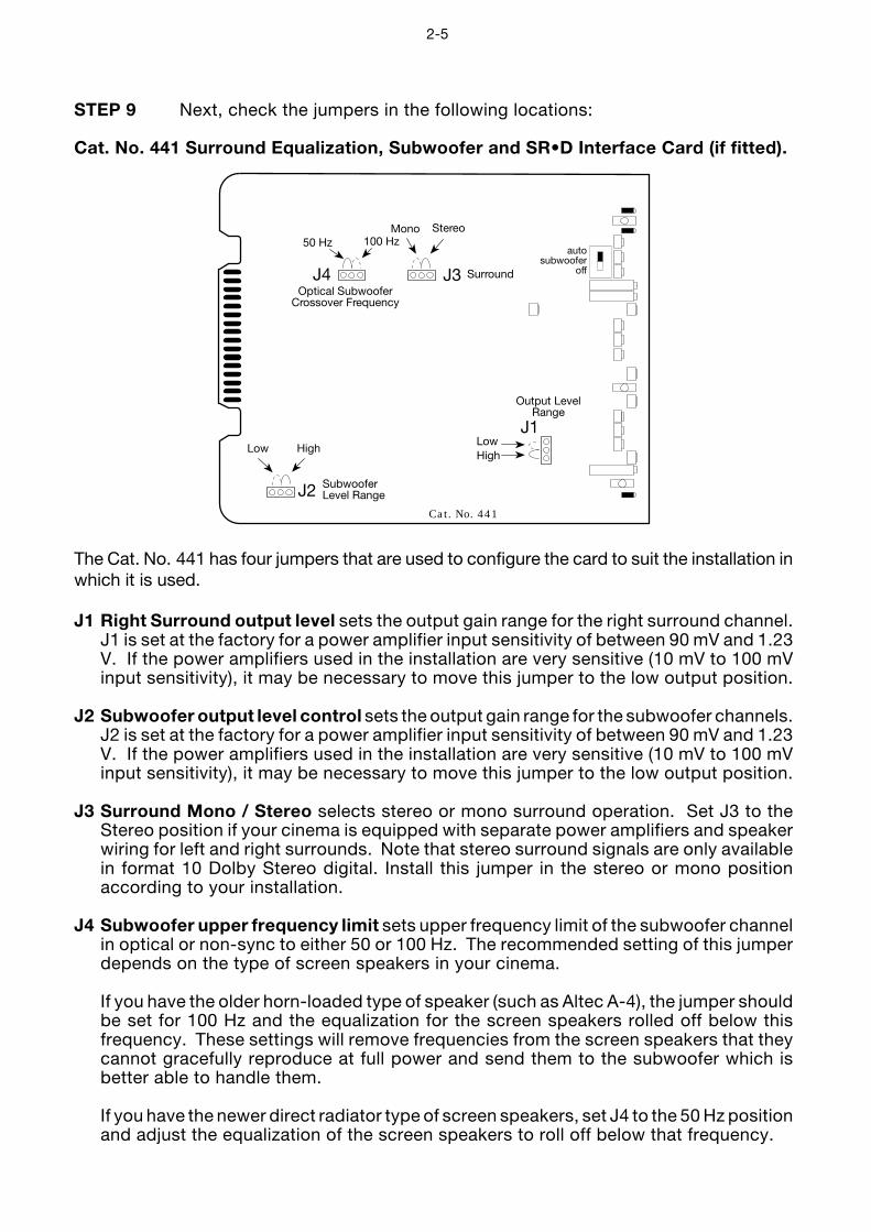
STEP 9 Next, check the jumpers in the following locations:
Cat. No. 441 Surround Equalization, Subwoofer and SR•D Interface Card (if fitted).
J3
J2
High
Cat. No. 441
J1Low
SubwooferLevel Range
HighLow
Output LevelRange
J4Optical Subwoofer
Crossover Frequency
Surround
StereoMono100 Hz50 Hz
autosubwoofer
off
The Cat. No. 441 has four jumpers that are used to configure the card to suit the installation inwhich it is used.
J1 Right Surround output level sets the output gain range for the right surround channel.J1 is set at the factory for a power amplifier input sensitivity of between 90 mV and 1.23V. If the power amplifiers used in the installation are very sensitive (10 mV to 100 mVinput sensitivity), it may be necessary to move this jumper to the low output position.
J2 Subwoofer output level control sets the output gain range for the subwoofer channels.J2 is set at the factory for a power amplifier input sensitivity of between 90 mV and 1.23V. If the power amplifiers used in the installation are very sensitive (10 mV to 100 mVinput sensitivity), it may be necessary to move this jumper to the low output position.
J3 Surround Mono / Stereo selects stereo or mono surround operation. Set J3 to theStereo position if your cinema is equipped with separate power amplifiers and speakerwiring for left and right surrounds. Note that stereo surround signals are only availablein format 10 Dolby Stereo digital. Install this jumper in the stereo or mono positionaccording to your installation.
J4 Subwoofer upper frequency limit sets upper frequency limit of the subwoofer channelin optical or non-sync to either 50 or 100 Hz. The recommended setting of this jumperdepends on the type of screen speakers in your cinema.
If you have the older horn-loaded type of speaker (such as Altec A-4), the jumper shouldbe set for 100 Hz and the equalization for the screen speakers rolled off below thisfrequency. These settings will remove frequencies from the screen speakers that theycannot gracefully reproduce at full power and send them to the subwoofer which isbetter able to handle them.
If you have the newer direct radiator type of screen speakers, set J4 to the 50 Hz positionand adjust the equalization of the screen speakers to roll off below that frequency.
2-6
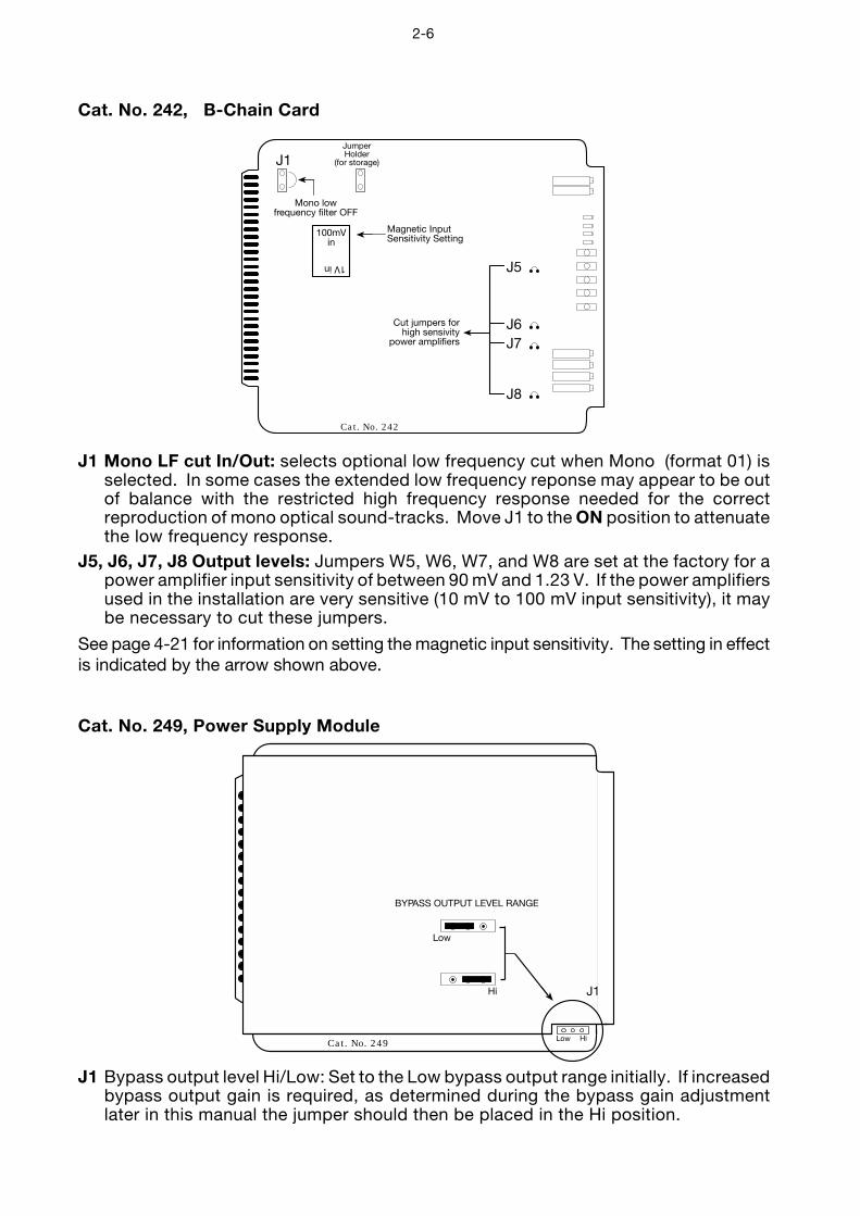
Cat. No. 242, B-Chain Card
JumperHolder
(for storage)J1
Cat. No. 242
Mono lowfrequency filter OFF
100mVin
1V in
Magnetic InputSensitivity Setting
J5
J6J7
J8
Cut jumpers forhigh sensivity
power amplifiers
J1 Mono LF cut In/Out: selects optional low frequency cut when Mono (format 01) isselected. In some cases the extended low frequency reponse may appear to be outof balance with the restricted high frequency response needed for the correctreproduction of mono optical sound-tracks. Move J1 to the ON position to attenuatethe low frequency response.
J5, J6, J7, J8 Output levels: Jumpers W5, W6, W7, and W8 are set at the factory for apower amplifier input sensitivity of between 90 mV and 1.23 V. If the power amplifiersused in the installation are very sensitive (10 mV to 100 mV input sensitivity), it maybe necessary to cut these jumpers.
See page 4-21 for information on setting the magnetic input sensitivity. The setting in effectis indicated by the arrow shown above.
Cat. No. 249, Power Supply Module
Low Hi
J1
Cat. No. 249
BYPASS OUTPUT LEVEL RANGE
Hi
Low
J1 Bypass output level Hi/Low: Set to the Low bypass output range initially. If increasedbypass output gain is required, as determined during the bypass gain adjustmentlater in this manual the jumper should then be placed in the Hi position.
2-7
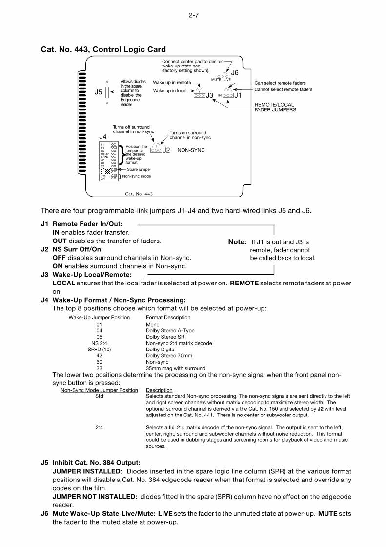
Cat. No. 443, Control Logic CardConnect center pad to desiredwake-up state pad(factory setting shown).
Cannot select remote fadersCan select remote faders
REMOTE/LOCALFADER JUMPERS
Turns off surroundchannel in non-sync Turns on surround
channel in non-sync
IN
MUTE LIVE
J1J3
Wake up in remote
Wake up in local
010405NS 2:4SR•D426022
STD2:4
J2Position thejumper tothe desiredwake-upformat
}Spare jumper
} Non-sync mode
NON-SYNC
Cat. No. 443
J5
J4
J6Allows diodesin the sparecolumn todisable theEdgecodereader
There are four programmable-link jumpers J1-J4 and two hard-wired links J5 and J6.
J1 Remote Fader In/Out:IN enables fader transfer.OUT disables the transfer of faders.
J2 NS Surr Off/On:OFF disables surround channels in Non-sync.ON enables surround channels in Non-sync.
J3 Wake-Up Local/Remote:LOCAL ensures that the local fader is selected at power on. REMOTE selects remote faders at poweron.
J4 Wake-Up Format / Non-Sync Processing:The top 8 positions choose which format will be selected at power-up:
Wake-Up Jumper Position Format Description01 Mono04 Dolby Stereo A-Type05 Dolby Stereo SR
NS 2:4 Non-sync 2:4 matrix decodeSR•D (10) Dolby Digital
42 Dolby Stereo 70mm60 Non-sync22 35mm mag with surround
The lower two positions determine the processing on the non-sync signal when the front panel non-sync button is pressed:
Non-Sync Mode Jumper Position DescriptionStd Selects standard Non-sync processing. The non-sync signals are sent directly to the left
and right screen channels without matrix decoding to maximize stereo width. Theoptional surround channel is derived via the Cat. No. 150 and selected by J2 with leveladjusted on the Cat. No. 441. There is no center or subwoofer output.
2:4 Selects a full 2:4 matrix decode of the non-sync signal. The output is sent to the left,center, right, surround and subwoofer channels without noise reduction. This formatcould be used in dubbing stages and screening rooms for playback of video and musicsources.
J5 Inhibit Cat. No. 384 Output:JUMPER INSTALLED: Diodes inserted in the spare logic line column (SPR) at the various formatpositions will disable a Cat. No. 384 edgecode reader when that format is selected and override anycodes on the film.JUMPER NOT INSTALLED: diodes fitted in the spare (SPR) column have no effect on the edgecodereader.
J6 Mute Wake-Up State Live/Mute: LIVE sets the fader to the unmuted state at power-up. MUTE setsthe fader to the muted state at power-up.
Note: If J1 is out and J3 isremote, fader cannotbe called back to local.
2-8
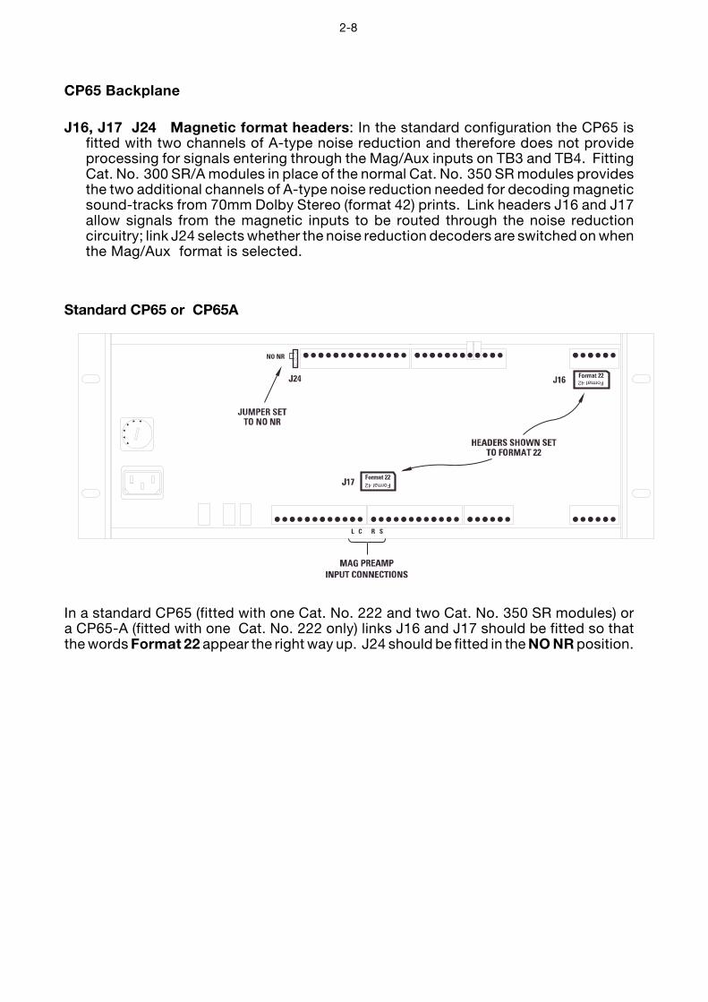
CP65 Backplane
J16, J17 J24 Magnetic format headers: In the standard configuration the CP65 isfitted with two channels of A-type noise reduction and therefore does not provideprocessing for signals entering through the Mag/Aux inputs on TB3 and TB4. FittingCat. No. 300 SR/A modules in place of the normal Cat. No. 350 SR modules providesthe two additional channels of A-type noise reduction needed for decoding magneticsound-tracks from 70mm Dolby Stereo (format 42) prints. Link headers J16 and J17allow signals from the magnetic inputs to be routed through the noise reductioncircuitry; link J24 selects whether the noise reduction decoders are switched on whenthe Mag/Aux format is selected.
Standard CP65 or CP65A
In a standard CP65 (fitted with one Cat. No. 222 and two Cat. No. 350 SR modules) ora CP65-A (fitted with one Cat. No. 222 only) links J16 and J17 should be fitted so thatthe words Format 22 appear the right way up. J24 should be fitted in the NO NR position.
2-9
CP65-300
In a CP65-300 (when Cat. No. 300 modules are fitted in place of the normal Cat. No. 350modules) J16 and J18 should be rotated so that the words “Format 42” appears the rightway up. With J24 in the “NR” position input signals will be A-type decoded when theMag/Aux format is selected. With J24 in the “NO NR” position signals pass through thenoise reduction modules but the processing will be turned off. If both of these processingoptions are required frequently an external switch may be connected to J24.
NOTE: To play 70mm Dolby Stereo (Format 42) with a CP65-300, the left, center, right,and surround outputs of the magnetic pre-amp must be connected to TB6 and the Leand Re outputs must be connected to TB4. If changing between an optical format andmag format 42 is required, external switching may be added (or J16 must be manuallyrotated to the Format 22 position for optical playback and to Format 42 for 70mmplayback).
2-10
Cat. No. 241 Surround Equalization and Optical Bass Extension. Module (iffitted).
Highsubwoofer
output
Cat. No. 241
J1
Lowsubwoofer
output
J1 Optical Bass Extension output level: sets the output level range for the subwooferchannel. In the HIGH position J1 is set at the factory for a power amplifier inputsensitivity of between 90 mV and 1.23 V. If the power amplifiers used in theinstallation are very sensitive (10 mV to 100 mV input sensitivity), it may be necessaryto set J1 to the LOW position. If you are unsure of the sensitivity of your poweramplifiers set J1 to the LOW position initially. If the high output position is requiredthis will be determined during OBE alignment.
2-11
STEP 10 If they are not already installed in the CP65 card cage, install all of the cardsfor your system as shown.
Card Descriptions:
Dol
by
Dol
by
Dol
by
Dol
by
Dol
byS
RRS
Dol
byTHESE MODULES ARE
NECESSARY FOR BYPASSOPERATION
2-channel
Lt
Rt
n-syncsurrgain
Q powersupplystatus
(L,R)Lt/Rt
(C)Lt
450 A
(S)Rt
450 A
on
gnd
Cat. No.242
B chainmodule
transformer259
regulatorvoltage
249control
443
subwooferand
surround441
REQ64
CEQ64
LEQ64
decoder2:4 ch
150
A-type
222300 SR/A
350 SR300 SR/A
350 SR
preampoptical
240A(spare)
240ACat. No.Cat. No.Cat. No.Cat. No.Cat. No.Cat. No.Cat. No.Cat. No.Cat. No.Cat. No.Cat. No.Cat. No.Cat. No.
Rt
Lt
Lt
Rt
gndProj. 2
hf
GAIN
hf
GAIN
Rt tp
Rt
Lt
Lt tp
Proj. 1
hf
GAIN
hf
GAIN
signalpresent
4
presentsignal
L
C
R
S
delay
Rt tp
Lt tp
gainmono
15V15V24V
gain
bypass
non-sync
gain
pointstest
mono eq
Ls
R
C
L
Ls
R
C
L
gnd
Ls
R
C
L
R
L
signalpresent
presentsignal
gndgainbass
Q
mid freq
cut
treble
tp
bass
Q
freqmid
cut
treble
gainmag/digopt gain
offauto freq
cut
tppresent
signal
Subw
oofe
rLe
ft Su
rrou
ndRi
ght S
urro
und
spare
sparenormal
bypass
fuse
fuse
(reset)
normal bypass
SlotNo. Card Function1 Slot for spare Spare location for Cat. No. 240A (or the older
Cat. No. 240A Card Cat. No. 240).
2 Cat. No. 240A Amplifies the outputs of the solar cell in theOptical Preamplifier selected projector. Electronic switches selectCard projector No. 1 or 2. The older Cat. No. 240 may also
be used.
3,4 Cat. No. 350 Each module contains a single channelSpectral recording of Dolby spectral recording (SR) processingModules for optical soundtracks recorded with Dolby SR (Format
05).
Note:1) Some installations may use two Cat. No. 300 SR/AProcessing modules in place of Cat. No. 350.
2) In CP65-A, Cat. No. 350/300 are not fitted and theslots are empty.
2-12
SlotNo. Card Function5 Cat. No. 222 Contains two channels of Dolby A-type noise
Two-channel Noise reduction circuitry with LED indicators to setReduction Module Dolby Level.
6 Cat. No. 150 Derives left, right, center, and surround2:4 Channel Decoder information from the two optical tracks on theCard film.
7,8,9 Cat. No. 64B Contains treble and bass controls and 27Equalizer Module third-octave equalizer controls. One card is used
for each front channel: left, center, right.
10 Cat No. 441 (1) Provides equalization for the surroundSurround Equalizer, channels.Subwoofer card. (2) Extracts low frequency information from the L,
C, and R signals and sends this signal to asubwoofer output through an equalizer and a fadercircuit.
(3) Provides Subwoofer input for magnetic anddigital soundtracks and Stereo Surround from aDolby Digital adapter.
Note: Cat. No. 241 may also be used in thisposition but does not provide (3) above.
11 Cat. No. 242 Contains the signal processing circuitry for theB-Chain Card B-Chain except for the equalizers. Has input buffers
and filters for non-sync, aux and magnetic sources,electronic switches to select input sources, a 4-channel fader circuit, and output levelpotentiometers for L,C,R,S.
12 Cat. No. 443 Configures the CP65 for the selected format.Control Logic Card Also contains fader mute and fader local/remote
status circuits. Generates control logic signals forother cards in the CP65. Its inputs are the Cat.No. 447 front panel controls, external remoteboxes, or automation inputs to the CP65. It alsocontains a jumper block to enable the wake-upcondition to be preselected.
2-13
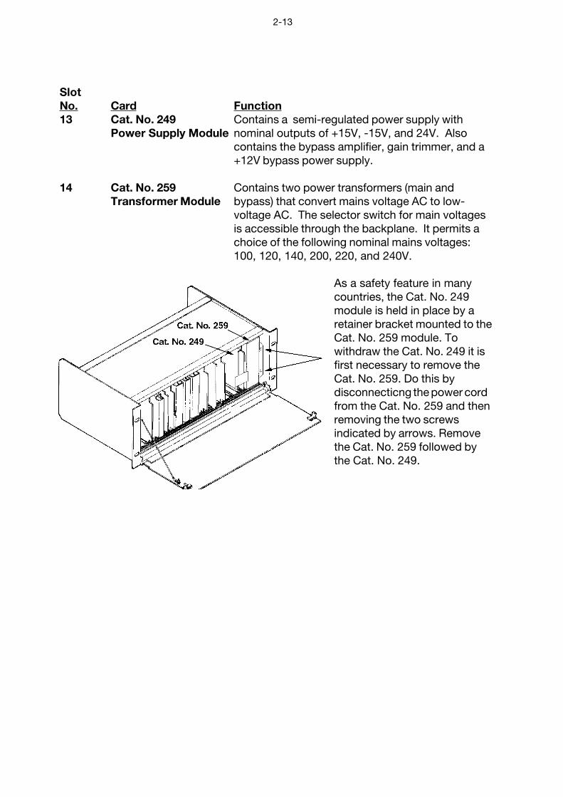
SlotNo. Card Function13 Cat. No. 249 Contains a semi-regulated power supply with
Power Supply Module nominal outputs of +15V, -15V, and 24V. Alsocontains the bypass amplifier, gain trimmer, and a+12V bypass power supply.
14 Cat. No. 259 Contains two power transformers (main andTransformer Module bypass) that convert mains voltage AC to low-
voltage AC. The selector switch for main voltagesis accessible through the backplane. It permits achoice of the following nominal mains voltages:100, 120, 140, 200, 220, and 240V.
As a safety feature in manycountries, the Cat. No. 249module is held in place by aretainer bracket mounted to theCat. No. 259 module. Towithdraw the Cat. No. 249 it isfirst necessary to remove theCat. No. 259. Do this bydisconnecticng the power cordfrom the Cat. No. 259 and thenremoving the two screwsindicated by arrows. Removethe Cat. No. 259 followed bythe Cat. No. 249.
2-14
ADDITIONAL INFORMATION FOR THE SAFE OPERATION OF THE CP65
To ensure proper operation and guard against potential shock hazard, the CP65 must beconnected only to a properly wired, grounded (earthed) mains receptacle. If you areuncertain about the wiring of your mains outlet do not use it. Consult a qualified electrician.The power cord is supplied with either a standard U.S.A. three-prong plug or withunterminated leads for use in other countries. The wires are colored in accordance with thefollowing international code:
International U.S.live or hot brown blackneutral blue whiteearth green/yellow green/yellow
Before the power cord is connected to the CP65, ensure that a qualified electrician haswired the cord following the code.
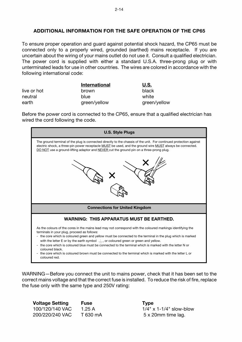
U.S. Style Plugs
The ground terminal of the plug is connected directly to the chassis of the unit. For continued protection againstelectric shock, a three-pin power receptacle MUST be used, and the ground wire MUST always be connected.DO NOT use a ground-lifting adaptor and NEVER cut the ground pin on a three-prong plug.
Connections for United Kingdom
WARNING: THIS APPARATUS MUST BE EARTHED.
As the colours of the cores in the mains lead may not correspond with the coloured markings identifying theterminals in your plug, proceed as follows:- the core which is coloured green and yellow must be connected to the terminal in the plug which is marked
with the letter E or by the earth symbol , or coloured green or green and yellow.- the core which is coloured blue must be connected to the terminal which is marked with the letter N or
coloured black.- the core which is coloured brown must be connected to the terminal which is marked with the letter L or
coloured red.
WARNING—Before you connect the unit to mains power, check that it has been set to thecorrect mains voltage and that the correct fuse is installed. To reduce the risk of fire, replacethe fuse only with the same type and 250V rating:
Voltage Setting Fuse Type100/120/140 VAC 1.25 A 1/4" x 1-1/4" slow-blow200/220/240 VAC T 630 mA 5 x 20mm time lag.
2-15
GB
D
F
I
S
NL
IMPORTANT SAFETY NOTICEThis unit complies with the safety standard IEC65. To ensure safe operation and to guardagainst potential shock hazard or risk of fire, the following must be observed:• If the unit has a voltage selector, ensure that it is set to the correct mains voltage for your supply. If there
is no voltage selector, ensure that your supply is in the correct range for the input requirement of the unit.• Ensure fuses fitted are the correct rating and type as marked on the unit.• The unit must be earthed by connecting to a correctly wired and earthed power outlet.• The power cord supplied with this unit must be wired as follows:
Live—Brown Neutral—Blue Earth—Green/Yellow
IMPORTANT – NOTE DE SECURITECe materiel est conforme à la norme IEC65. Pour vous assurer d'un fonctionnement sans danger et de prévenirtout choc électrique ou tout risque d'incendie, veillez à observer les recommandations suivantes.• Le selecteur de tension doit être placé sur la valeur correspondante à votre alimentation réseau.• Les fusibles doivent correspondre à la valeur indiquée sur le materiel.• Le materiel doit être correctement relié à la terre.• Le cordon secteur livré avec le materiel doit être cablé de la manière suivante:
Phase—Brun Neutre—Bleu Terre—Vert/Jaune
WICHTIGER SICHERHEITSHINWEISDieses Gerät entspricht der Sicherheitsnorm IEC65. Für das sichere Funktionieren des Gerätes und zur Unfallverhütung(elektrischer Schlag, Feuer) sind die folgenden Regeln unbedingt einzuhalten:• Der Spannungswähler muß auf Ihre Netzspannung eingestellt sein.• Die Sicherungen müssen in Type und Stromwert mit den Angaben auf dem Gerät übereinstimmen.• Die Erdung des Gerätes muß über eine geerdete Steckdose gewährleistet sein.• Das mitgelieferte Netzkabel muß wie folgt verdrahtet werden:
Phase—braun Nulleiter—blau Erde—grün/gelb
NORME DI SICUREZZA – IMPORTANTEQuesta apparecchiatura è stata costruita in accordo alle norme di sicurezza IEC 65. Per una perfetta sicurezza edal fine di evitare eventuali rischi di scossa êlettrica o d'incendio vanno osservate le seguenti misure di sicurezza:• Assicurarsi che il selettore di cambio tensione sia posizionato sul valore corretto.• Assicurarsi che la portata ed il tipo di fusibili siano quelli prescritti dalla casa costruttrice.• L'apparecchiatura deve avere un collegamento di messa a terra ben eseguito; anche la connessione rete deve
avere un collegamento a terra.• Il cavo di alimentazione a corredo dell'apparecchiatura deve essere collegato come segue:
Filo tensione—Marrone Neutro—Blu Massa—Verde/Giallo
AVISO IMPORTANTE DE SEGURIDADEsta unidad cumple con la norma de seguridad IEC65. Para asegurarse un funcionamientoseguro y prevenir cualquier posible peligro de descarga o riesgo de incendio, se han de observarlas siguientes precauciones:• Asegúrese que el selector de tensión esté ajustado a la tensión correcta para su alimentación.• Asegúrese que los fusibles colocados son del tipo y valor correctos, tal como se marca en la unidad.• La unidad debe ser puesta a tierra, conectándola a un conector de red correctamente cableado y puesto a tierra.• El cable de red suministrado con esta unidad, debe ser cableado como sigue:
Vivo—Marrón Neutro—Azul Tierra—Verde/Amarillo
VIKTIGA SÄKERHETSÅTGÄRDER!Denna enhet uppfyller säkerhetsstandard IEC65. För att garantera säkerheten och gardera moteventuell elchock eller brandrisk, måste följande observeras:• Kontrollera att spänningsväljaren är inställd på korrekt nätspänning.• Konrollera att säkringarna är av rätt typ och för rätt strömstyrka så som anvisningarna på enheten föreskriver
.
• Enheten måste vara jordad genom anslutning till ett korrekt kopplat och jordat el-uttag.• El-sladden som medföljer denna enhet måste kopplas enligt foljande:
Fas—Brun Neutral—Blå Jord—Grön/Gul
BELANGRIJK VEILIGHEIDS-VOORSCHRIFT:Deze unit voldoet aan de IEC65 veiligheids-standaards. Voor een veilig gebruik en om het gevaar van electrischeschokken en het risico van brand te vermijden, dienen de volgende regels in acht te worden genomen:• Controleer of de spanningscaroussel op het juiste Voltage staat.• Gebruik alleen zekeringen van de aangegeven typen en waarden.• Aansluiting van de unit alleen aan een geaarde wandcontactdoos.• De netkabel die met de unit wordt geleverd, moet als volgt worden aangesloten:
Fase—Bruin Nul—Blauw Aarde—Groen/Geel
E
IEC NOTICES
2-16
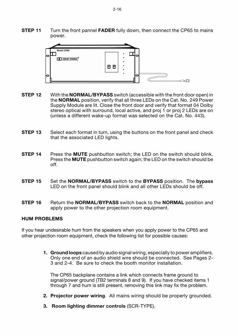
STEP 11 Turn the front pannel FADER fully down, then connect the CP65 to mainspower.
Model CP65
STEP 12 With the NORMAL/BYPASS switch (accessible with the front door open) inthe NORMAL position, verify that all three LEDs on the Cat. No. 249 PowerSupply Module are lit. Close the front door and verify that format 04 Dolbystereo optical with surround, local active, and proj 1 or proj 2 LEDs are on(unless a different wake-up format was selected on the Cat. No. 443).
STEP 13 Select each format in turn, using the buttons on the front panel and checkthat the associated LED lights.
STEP 14 Press the MUTE pushbutton switch; the LED on the switch should blink.Press the MUTE pushbutton switch again; the LED on the switch should beoff.
STEP 15 Set the NORMAL/BYPASS switch to the BYPASS position. The bypassLED on the front panel should blink and all other LEDs should be off.
STEP 16 Return the NORMAL/BYPASS switch back to the NORMAL position andapply power to the other projection room equipment.
HUM PROBLEMS
If you hear undesirable hum from the speakers when you apply power to the CP65 andother projection room equipment, check the following list for possible causes:
1. Ground loops caused by audio signal wiring, especially to power amplifiers.Only one end of an audio shield wire should be connected. See Pages 2-3 and 2-4. Be sure to check the booth monitor installation.
The CP65 backplane contains a link which connects frame ground tosignal/power ground (TB2 terminals 8 and 9). If you have checked items 1through 7 and hum is still present, removing this link may fix the problem.
2. Projector power wiring. All mains wiring should be properly grounded.
3. Room lighting dimmer controls (SCR-TYPE).

2-17
4. Power amplifiers. Disconnect from the CP65 and ground the inputs todetermine if the power amplifiers are causing hum problems.
With CP65 FADER turned up and format 04 selected:
5. Solar cell wiring. Check the shield connections. Cell wiring should beplaced away from mains and other wiring.
6. Exciter lamp power supply. Check for ripple on the DC power supplyoutputs. Some old exciter lamp power supplies and emergency suppliesprovide AC to the lamp. The resulting hum makes them totally unsuitablefor a stereo playback system. Such exciter supplies should be replaced.
7. Projection room lighting/solar cells. Ambient lighting, especially florescenttubes, can leak into the solar cell area and cause hum.
3-1
SECTION 3AN OVERVIEW OF THE ALIGNMENT PROCEDURE
This section is an overview of the general principles involved in the alignment of Dolbycinema equipment. It is useful to develop an understanding of why the CP65 is alignedas described in this manual. If the installer is already familiar with these principles, oris in a hurry to complete the installation, this section may be read later. Continue theinstallation procedure beginning with Section 4.
1. Aligning the A-Chain
The A-Chain is first calibrated by use of the Cat. No. 69 Dolby Tone test film to establish thecorrect Dolby operating level within the CP65 and to ensure correct tracking of the Dolby noisereduction circuit.
Pink noise is used for equalization of the A-chain. (Pink noise is similar to white noise butprovides equal energy per octave of bandwidth.) Pink noise for A-chain alignment is recordedon the other side of the Cat. No. 69 test film. The output should be displayed on a Real TimeAnalyzer (RTA) so adjustments can be made quickly.
The optical slit is the key element in the A-chain because it imposes the initial limitation on thehigh-frequency response of the system. Light from the exciter lamp passes through the opticalslit and is focussed on the optical soundtracks on the film. The light that passes through thesoundtracks falls on the stereo solar cell which generates an electrical signal that isproportional to the audio signal recorded on the optical soundtracks. The slit introduces highfrequency loss which must be compensated by circuitry in the Cat. No. 240A opticalpreamplifier (see Appendix B).
The slit image must be correctly focussed on the film and must be precisely at right angles tothe direction of film movement in order to maintain the correct phase relationships betweenthe two optical tracks. Any azimuth error will show as a loss of high frequency in the frontchannels and potentially excessive crosstalk in the surround channels.
Each channel in the Cat. No. 240A optical preamplifier is equipped with a slit loss equalizercontrol. Adjustment of this control shifts a fixed amount of boost upward or downward infrequency, but the shape of the curve remains constant. A perfectly flat response up to aminimum of 12 kHz can be achieved possible. See Appendix B for further details.
2. Aligning the B-Chain
In most theatre playback systems, the acoustical qualities of the theatre are difficult tochange. Therefore, the primary area where improvement is possible is correctingloudspeaker response errors caused by the theatre acoustic environment.
It is not practical for the entire cinema industry to standardize on a single make and model ofloudspeaker. In any event, the different acoustical characteristics of individual theatreswould, to some extent, negate any such standardized speakers. Electronic equalization ofeach loudspeaker system achieves consistent results in a broad spectrum of environments,
3-2
and with a broad range of speakers. Accurate equalization requires the use of standardizedacoustic measurement procedures.
A pink noise generator provides a continuous random noise signal that covers the totalbandwidth and is used to measure and adjust the response of the loudspeakers. The use ofrandom noise eliminates the problems inherent with tones (standing wave patterns in thetheatres) and enables the frequency response of the entire system to be observed. Eachchannel can be measured and adjusted independently of the other channels.
A calibrated microphone is placed in the auditorium to receive the pink noise reproduced bythe loudspeaker; the output of the microphone is fed to a real time analyzer (RTA). The RTAdisplays the complete audio spectrum received by the microphone in the form of a frequencyresponse curve. Pure pink noise would yield a “flat” horizontal line on the RTA. Thus, the effectof adjustments to the equalizers is quickly and easily seen.
One of the problems inherent in equalization is the nature of the environment. In an openspace, a perfect loudspeaker, radiating a perfectly flat response in all directions, placed infront of a perfectly flat microphone, producing perfectly flat response to sounds arriving fromall directions, will produce a perfectly flat response on the RTA from pink noise. In an enclosedspace such as a theatre, the results are different. When the pink noise generator is first turnedon, all of the sound that initially reaches the microphone comes directly from the loudspeaker;the response is flat–for a few milliseconds. Then reflected sound from the walls, ceiling, floor,seats, etc. starts to arrive at the microphone together with the direct sound from theloudspeaker. This indirect or reflected sound reinforces the direct sound. The system soonsettles into an equilibrium condition. As much energy is being absorbed at the walls, ceiling,etc. as is fed into the room. Since high and mid frequency energy is absorbed when soundis reflected, the displayed response appears to have a rising bass and a falling treblecharacteristic. At first glance, rolling off the bass and boosting the high frequencies mayappear to be the logical approach for a flat steady-state response, but such an arrangementworks only on sustained sounds. Dialogue contains short, impulsive sounds and will yield amuch-too-bright result because there is no time for reverberation to build and add to theoriginal sound. What is required is a curve that favors such impulsive “first arrival” sound andimplies the same gently falling response that is observed when the output of an idealloudspeaker is measured with a perfect microphone in the theatre.
The amount of reverberation varies with frequency and the higher the frequency the more thetreble will be absorbed rather than being reflected. A typical reverberation curve in a theatrerolls off at about 3 dB per octave above 2 kHz. This characteristic is used to define thestandard steady-state response curve for all dubbing theatres in which Dolby stereo films aremixed and for all Dolby stereo-equipped cinemas.
The size of the theatre affects the reverberation time and, therefore, the measurement offrequency response. After alignment to this standard curve, some slight adjustment of highfrequency slope may be found necessary for extremely large or small theatres. The treblecontrol on the Cat. No. 64 Equalizer card can be adjusted to reduce the output on the responsecurve by approximately 1 dB at 8 kHz for very large theatres; an increase of 1 dB at 8 kHz maybe in order for a very small theatre. Any such adjustment should be based on an evaluationby ear of actual known films rather than as a rule of thumb.
3-3
Many loudspeakers used in theatres are far from ideal and require boosting of the low- andhigh-frequency extremes in order to produce an approximation of the standard referenceresponse curve. Bass and treble controls—centered on the turnover points of typicalloudspeakers—lift the ends of the spectrum without the need for large amounts of narrow-band boost from the third-octave controls in the Cat. No. 64 cards. The third-octave controlsare used for minor adjustments that are required to smooth the frequency response curve.
The final factor is masking of the screen. Most stereo films today are shown in a wide-screenformat. The masking curtains of the screen must be drawn back sufficiently to clear the leftand right speakers before any adjustments or measurements are made. The treble hornsshould clear the screen frame and be mounted as close as possible to the screen.Conventional black felt side masking can severely curtail high frequency response.Consequently, there would be severe losses if the left and right loudspeakers were equalizedwith the masking open as for a 2.35:1 film, and then the masking were brought in for a 1.85:1film, thus obscuring the outer speakers. To avoid this problem, some theatres have installedacoustically transparent masking cloth, and others leave the masking open whenever they areshowing a 1.85:1 film with a stereo soundtrack. Moving the speakers towards the center ofthe screen so as to clear heavy masking is not a good solution, since the stereo sound widthwould be degraded.
Repainted screens cannot be used for quality sound playback, since the perforations whichallow the high frequencies through the screen become clogged with paint.

4-1
SECTION 4A-CHAIN ALIGNMENT
The A-chain is the part of the sound system that covers the film path, solar cell, opticalpreamplifier, slit loss equalizer and Dolby noise reduction circuit.
The CP65 does not contain a magnetic A-chain but has facilities for switching externalmagnetic preamplifiers into the B-chain. An overview of external magnetic A-chain adjustmentsis given at the end of this section.
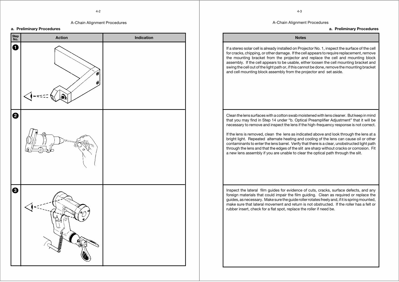
A-Chain Alignment Procedures
StepNo.
4-2
IndicationAction
a. Preliminary Procedures
1
2
3
A-Chain Alignment Procedures
Notes
4-3
a. Preliminary Procedures
Inspect the lateral film guides for evidence of cuts, cracks, surface defects, and anyforeign materials that could impair the film guiding. Clean as required or replace theguides, as necessary. Make sure the guide roller rotates freely and, if it is spring mounted,make sure that lateral movement and return is not obstructed. If the roller has a felt orrubber insert, check for a flat spot, replace the roller if need be.
Clean the lens surfaces with a cotton swab moistened with lens cleaner. But keep in mindthat you may find in Step 14 under “b. Optical Preamplifier Adjustment” that it will benecessary to remove and inspect the lens if the high-frequency response is not correct.
If the lens is removed, clean the lens as indicated above and look through the lens at abright light. Repeated alternate heating and cooling of the lens can cause oil or othercontaminants to enter the lens barrel. Verify that there is a clear, unobstructed light paththrough the lens and that the edges of the slit are sharp without cracks or corrosion. Fita new lens assembly if you are unable to clear the optical path through the slit.
If a stereo solar cell is already installed on Projector No. 1, inspect the surface of the cellfor cracks, chipping, or other damage. If the cell appears to require replacement, removethe mounting bracket from the projector and replace the cell and mounting blockassembly. If the cell appears to be usable, either loosen the cell mounting bracket andswing the cell out of the light path or, if this cannot be done, remove the mounting bracketand cell mounting block assembly from the projector and set aside.
A-Chain Alignment Procedures
StepNo.
4-4
IndicationAction
70 TO 80%OF RATED VOLTAGE
a. Preliminary Procedures
✓
4
5
A-Chain Alignment Procedures
Notes
4-5
a. Preliminary Procedures
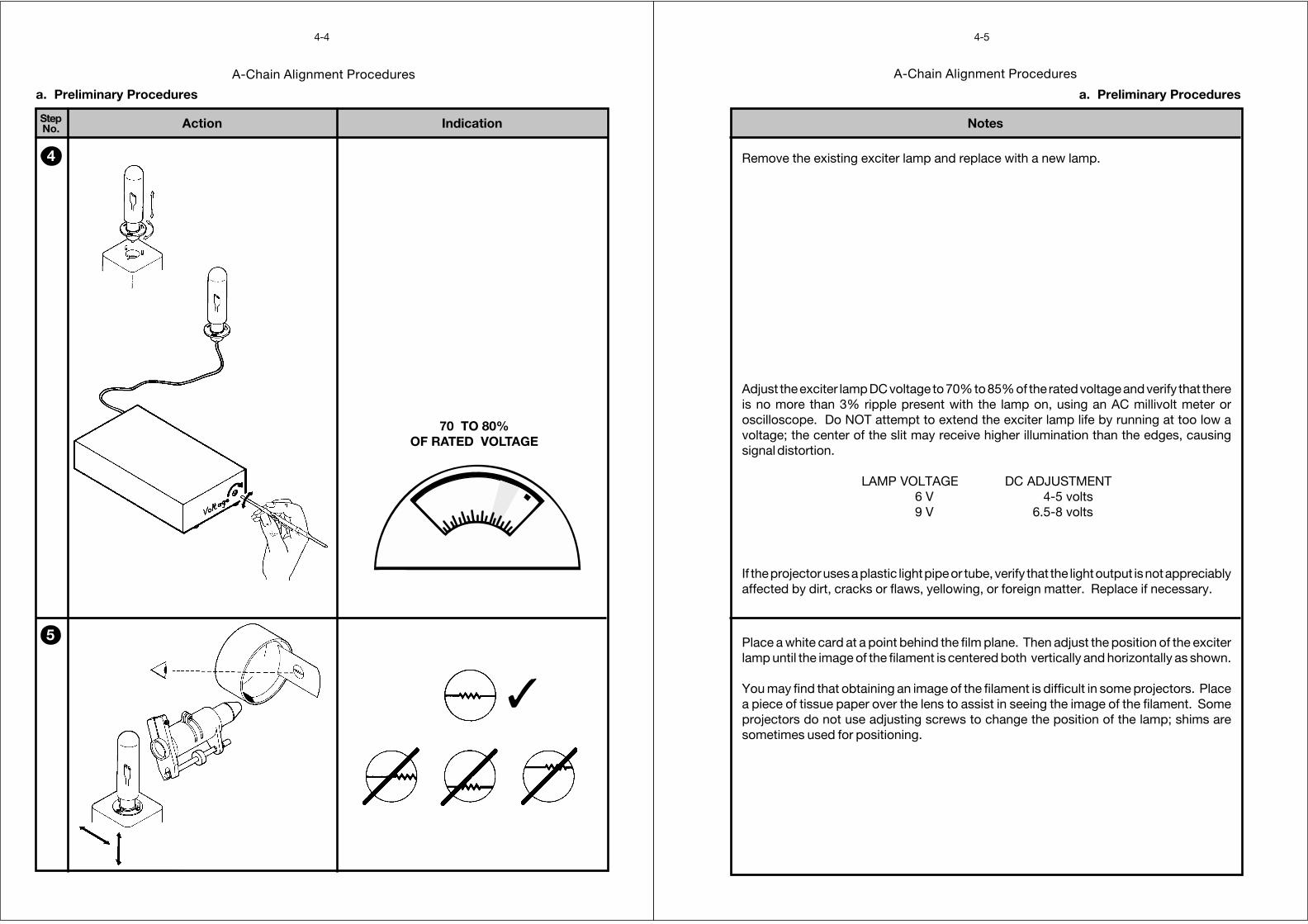
Remove the existing exciter lamp and replace with a new lamp.
Adjust the exciter lamp DC voltage to 70% to 85% of the rated voltage and verify that thereis no more than 3% ripple present with the lamp on, using an AC millivolt meter oroscilloscope. Do NOT attempt to extend the exciter lamp life by running at too low avoltage; the center of the slit may receive higher illumination than the edges, causingsignal distortion.
LAMP VOLTAGE DC ADJUSTMENT6 V 4-5 volts9 V 6.5-8 volts
If the projector uses a plastic light pipe or tube, verify that the light output is not appreciablyaffected by dirt, cracks or flaws, yellowing, or foreign matter. Replace if necessary.
Place a white card at a point behind the film plane. Then adjust the position of the exciterlamp until the image of the filament is centered both vertically and horizontally as shown.
You may find that obtaining an image of the filament is difficult in some projectors. Placea piece of tissue paper over the lens to assist in seeing the image of the filament. Someprojectors do not use adjusting screws to change the position of the lamp; shims aresometimes used for positioning.
A-Chain Alignment Procedures
StepNo.
4-6
IndicationAction
b. Optical Preamplifier Adjustments
1
2
3
Dolby
Rt
Lt
Lt
Rt
gndProj. 2
hf
GAIN
hf
GAIN
Rt tp
Rt
Lt
Lt tp
Proj. 1
hf
GAIN
hf
GAIN
signalpresent
Cat. No.240A
A-Chain Alignment Procedures
Notes
4-7
b. Optical Preamplifier Adjustments
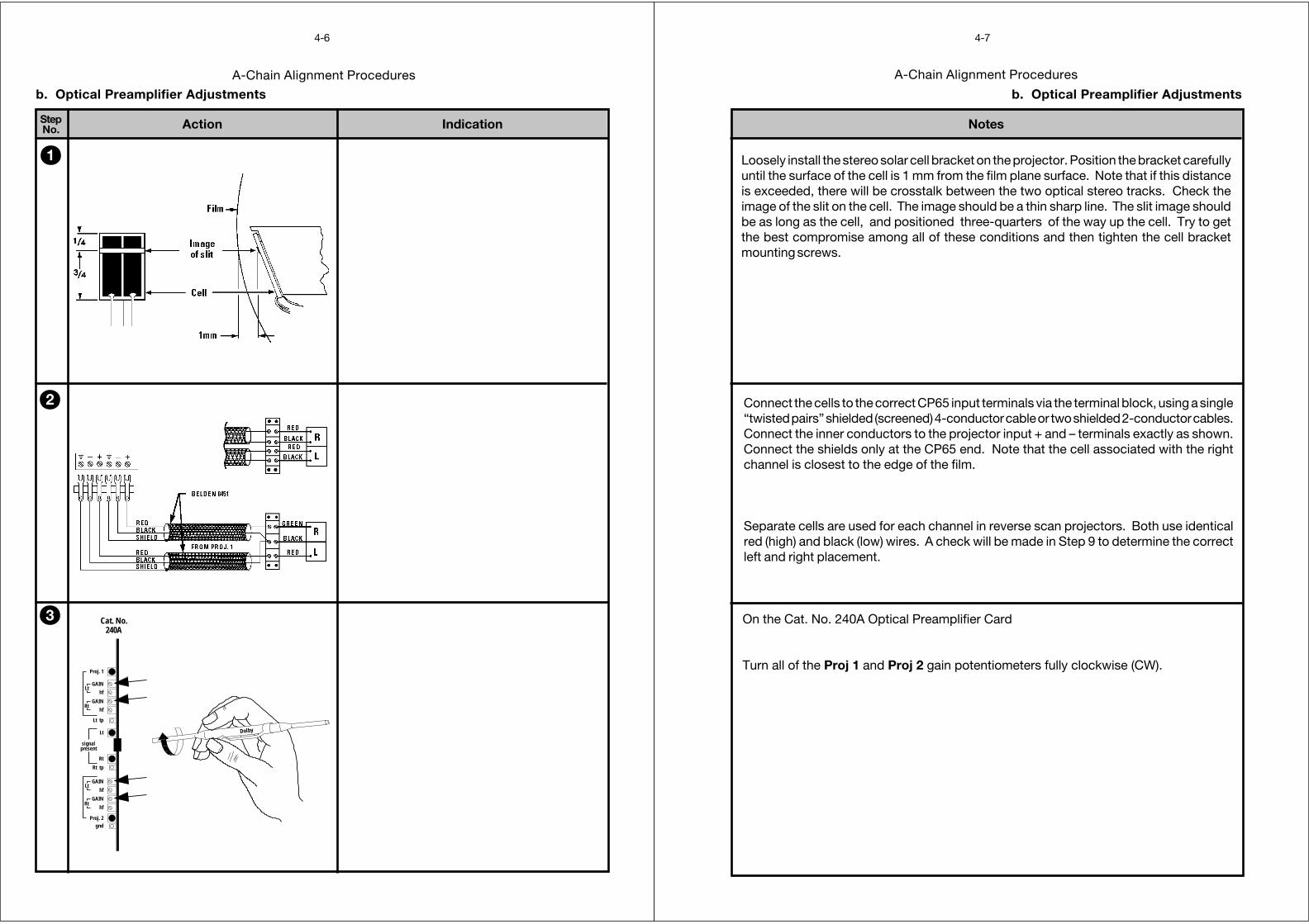
Connect the cells to the correct CP65 input terminals via the terminal block, using a single“twisted pairs” shielded (screened) 4-conductor cable or two shielded 2-conductor cables.Connect the inner conductors to the projector input + and – terminals exactly as shown.Connect the shields only at the CP65 end. Note that the cell associated with the rightchannel is closest to the edge of the film.
Separate cells are used for each channel in reverse scan projectors. Both use identicalred (high) and black (low) wires. A check will be made in Step 9 to determine the correctleft and right placement.
Loosely install the stereo solar cell bracket on the projector. Position the bracket carefullyuntil the surface of the cell is 1 mm from the film plane surface. Note that if this distanceis exceeded, there will be crosstalk between the two optical stereo tracks. Check theimage of the slit on the cell. The image should be a thin sharp line. The slit image shouldbe as long as the cell, and positioned three-quarters of the way up the cell. Try to getthe best compromise among all of these conditions and then tighten the cell bracketmounting screws.
On the Cat. No. 240A Optical Preamplifier Card
Turn all of the Proj 1 and Proj 2 gain potentiometers fully clockwise (CW).
A-Chain Alignment Procedures
StepNo.
4-8
IndicationAction
b. Optical Preamplifier Adjustments
Mono01
format
Mono01
format
4
5
6
Dolby
Rt
Lt
Lt
Rt
gndProj. 2
hf
GAIN
hf
GAIN
Rt tp
Rt
Lt
Lt tp
Proj. 1
hf
GAIN
hf
GAIN
signalpresent
Cat. No.240A
Cat. No. 240A
X
Y
Proj. 1 Status
RV101 GainRV102 hfRV201 GainRV202 hf
TP501 L tp
TP502 R tpR
L
RV301 GainRV302 hfRV401 GainRV402 hf
Proj. 2 Status
TP503 GND
R
R
L
L
SIGNALPRESENT
RTA
SCOPE
DUAL TRACEMODE
IN
NOTE: Be sure that the vertical range is set the same on both channels.
A-Chain Alignment Procedures
Notes
4-9
b. Optical Preamplifier Adjustments
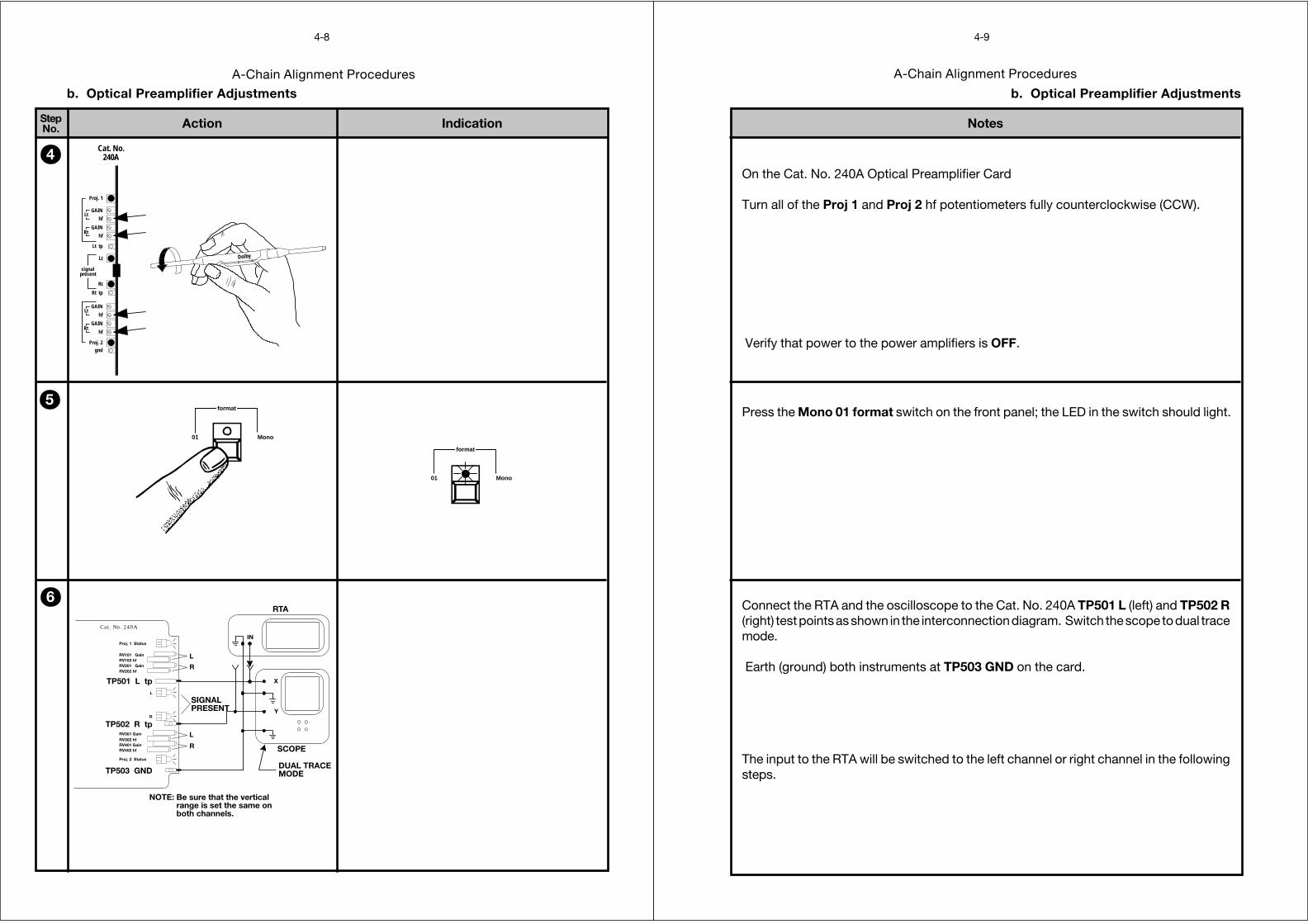
On the Cat. No. 240A Optical Preamplifier Card
Turn all of the Proj 1 and Proj 2 hf potentiometers fully counterclockwise (CCW).
Verify that power to the power amplifiers is OFF.
Press the Mono 01 format switch on the front panel; the LED in the switch should light.
Connect the RTA and the oscilloscope to the Cat. No. 240A TP501 L (left) and TP502 R(right) test points as shown in the interconnection diagram. Switch the scope to dual tracemode.
Earth (ground) both instruments at TP503 GND on the card.
The input to the RTA will be switched to the left channel or right channel in the followingsteps.
A-Chain Alignment Procedures
StepNo.
4-10
IndicationAction
b. Optical Preamplifier Adjustments
L L
L L
R R
R R
✓ ✓
OSCILLOSCOPE TRACES
Rt
Lt
CAT NO.222
7
8
Dolby
Rt
Lt
Lt
Rt
gndProj. 2
hf
GAIN
hf
GAIN
Rt tp
Rt
Lt
Lt tp
Proj. 1
hf
GAIN
hf
GAIN
signalpresent
Cat. No.240A
A-Chain Alignment Procedures
Notes
4-11
b. Optical Preamplifier Adjustments
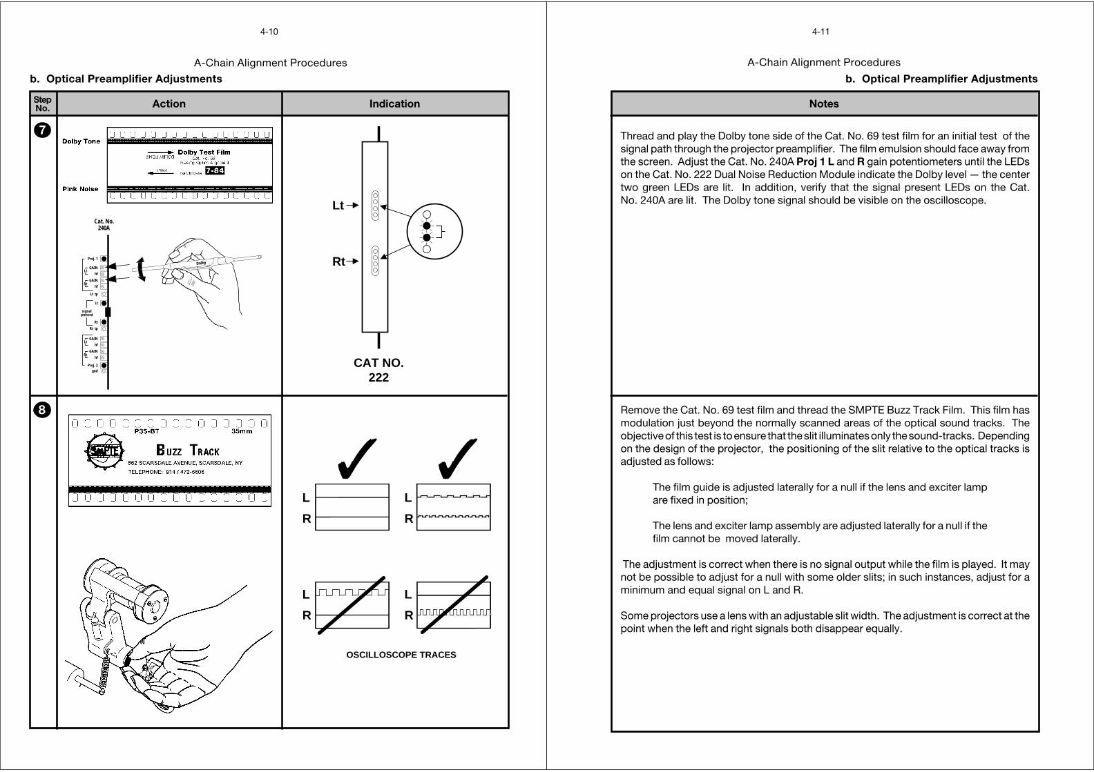
Thread and play the Dolby tone side of the Cat. No. 69 test film for an initial test of thesignal path through the projector preamplifier. The film emulsion should face away fromthe screen. Adjust the Cat. No. 240A Proj 1 L and R gain potentiometers until the LEDson the Cat. No. 222 Dual Noise Reduction Module indicate the Dolby level — the centertwo green LEDs are lit. In addition, verify that the signal present LEDs on the Cat.No. 240A are lit. The Dolby tone signal should be visible on the oscilloscope.
Remove the Cat. No. 69 test film and thread the SMPTE Buzz Track Film. This film hasmodulation just beyond the normally scanned areas of the optical sound tracks. Theobjective of this test is to ensure that the slit illuminates only the sound-tracks. Dependingon the design of the projector, the positioning of the slit relative to the optical tracks isadjusted as follows:
The film guide is adjusted laterally for a null if the lens and exciter lampare fixed in position;
The lens and exciter lamp assembly are adjusted laterally for a null if thefilm cannot be moved laterally.
The adjustment is correct when there is no signal output while the film is played. It maynot be possible to adjust for a null with some older slits; in such instances, adjust for aminimum and equal signal on L and R.
Some projectors use a lens with an adjustable slit width. The adjustment is correct at thepoint when the left and right signals both disappear equally.
A-Chain Alignment Procedures
StepNo.
4-12
IndicationnAction
b. Optical Preamplifier Adjustments
Rt
Lt
CAT NO.222
9
10
11 REPEAT AND
L R
98
OSCILLOSCOPE TRACE
CAT. NO. 97 TEST FILM
Rt
Lt
Lt
Rt
gndProj. 2
hfGAIN
hfGAIN
Rt tpRt
Lt
Lt tp
Proj. 1
hfGAIN
hfGAIN
signalpresent
Rt
Lt
Cat. No.240A
A-Chain Alignment Procedures
Notes
4-13
b. Optical Preamplifier Adjustments
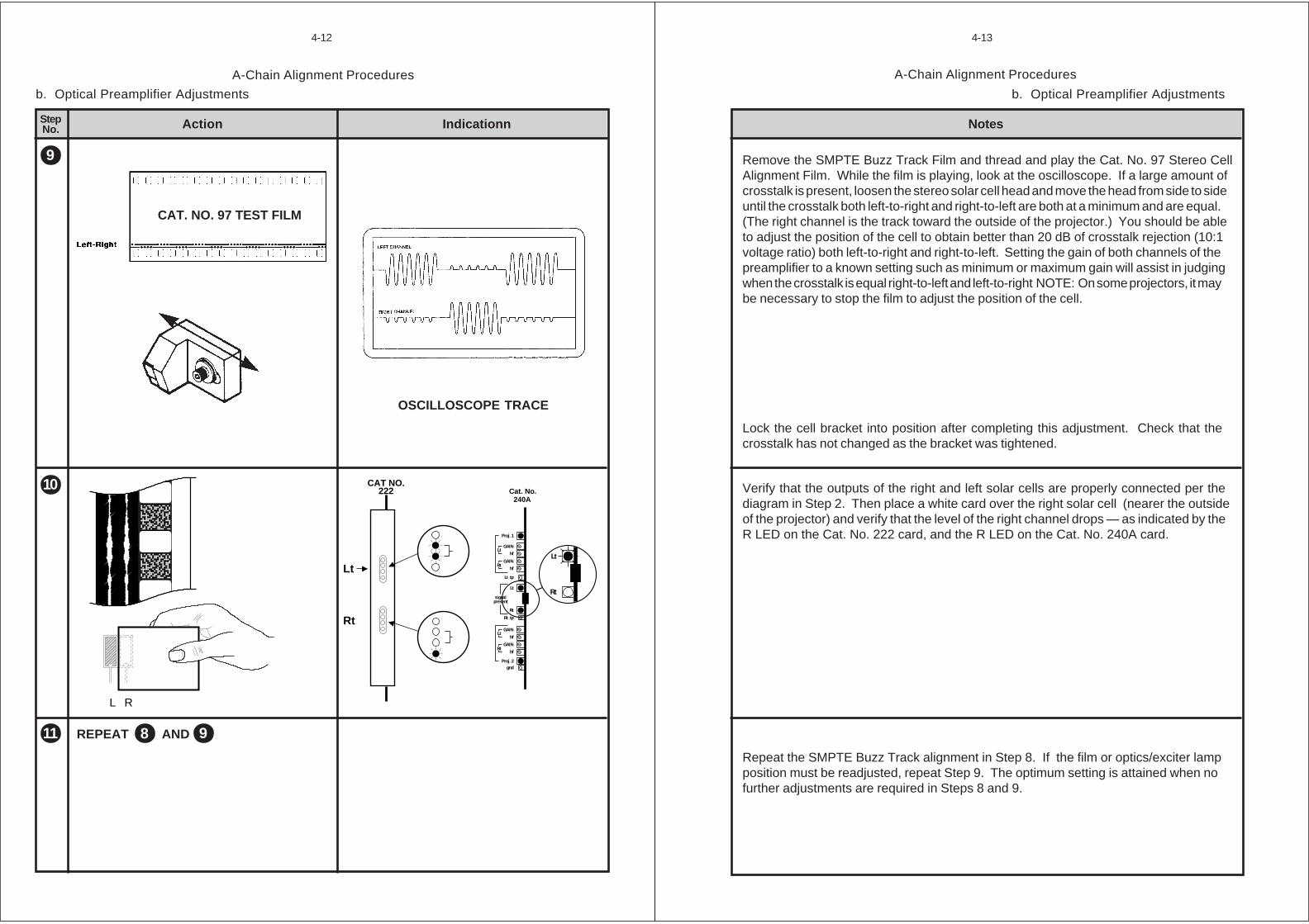
Remove the SMPTE Buzz Track Film and thread and play the Cat. No. 97 Stereo CellAlignment Film. While the film is playing, look at the oscilloscope. If a large amount ofcrosstalk is present, loosen the stereo solar cell head and move the head from side to sideuntil the crosstalk both left-to-right and right-to-left are both at a minimum and are equal.(The right channel is the track toward the outside of the projector.) You should be ableto adjust the position of the cell to obtain better than 20 dB of crosstalk rejection (10:1voltage ratio) both left-to-right and right-to-left. Setting the gain of both channels of thepreamplifier to a known setting such as minimum or maximum gain will assist in judgingwhen the crosstalk is equal right-to-left and left-to-right NOTE: On some projectors, it maybe necessary to stop the film to adjust the position of the cell.
Lock the cell bracket into position after completing this adjustment. Check that thecrosstalk has not changed as the bracket was tightened.
Verify that the outputs of the right and left solar cells are properly connected per thediagram in Step 2. Then place a white card over the right solar cell (nearer the outsideof the projector) and verify that the level of the right channel drops — as indicated by theR LED on the Cat. No. 222 card, and the R LED on the Cat. No. 240A card.
Repeat the SMPTE Buzz Track alignment in Step 8. If the film or optics/exciter lampposition must be readjusted, repeat Step 9. The optimum setting is attained when nofurther adjustments are required in Steps 8 and 9.
A-Chain Alignment Procedures
StepNo.
4-14
IndicationAction
✓
x
x
Out of phase
Incorrect azimuth
....00005555 ....1111 ....2222 ....4444 ....8888 1111....6666 3333....11115555 6666....3333 11112222....5555 kkkkHHHHzzzz
ddddBBBB
––––11110000
++++5555
0000
––––5555
++++11110000
OUT OFFOCUS
INTOFOCUS
X
✓
b. Optical Preamplifier Adjustments
112
113
OSCILLOSCOPE TRACES
RTA DISPLAY
Cat. No. 240A
X
Y
Proj. 1 Status
RV101 GainRV102 hfRV201 GainRV202 hf
TP501 L tp
TP502 R tpR
L
RV301 GainRV302 hfRV401 GainRV402 hf
Proj. 2 Status
TP503 GND
R
R
L
L
SIGNALPRESENT
RT
SCOPE
X-YMODE
IN
A-Chain Alignment Procedures
Notes
4-15
b. Optical Preamplifier Adjustments
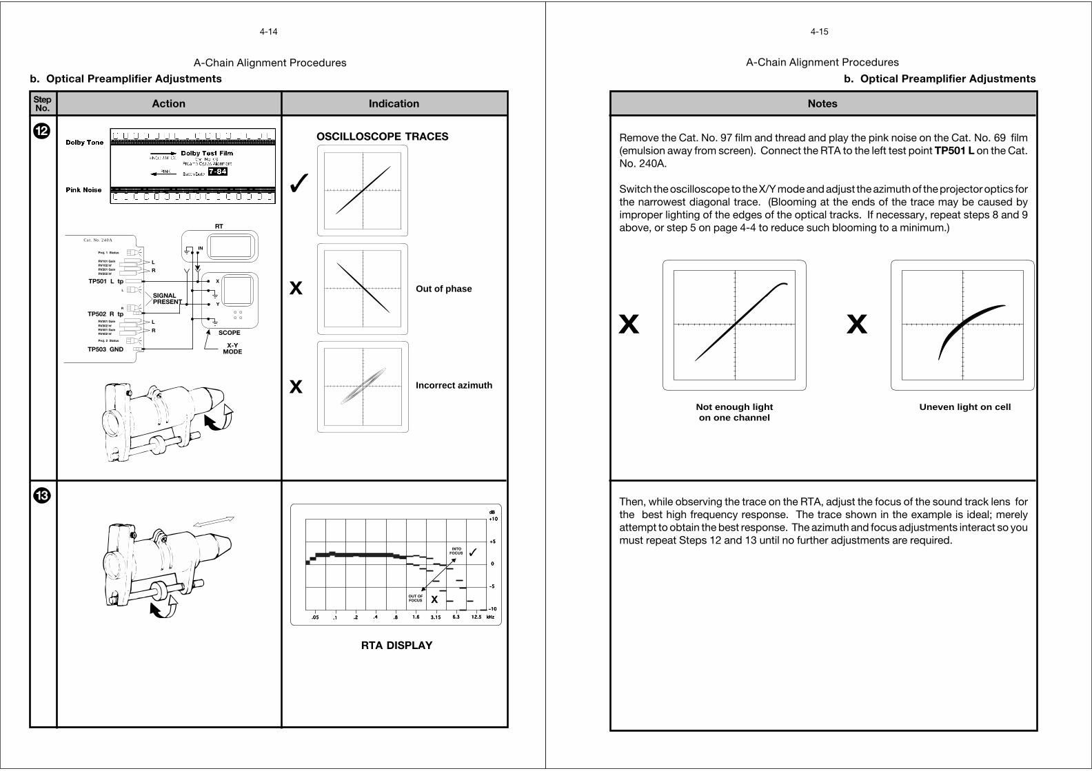
Remove the Cat. No. 97 film and thread and play the pink noise on the Cat. No. 69 film(emulsion away from screen). Connect the RTA to the left test point TP501 L on the Cat.No. 240A.
Switch the oscilloscope to the X/Y mode and adjust the azimuth of the projector optics forthe narrowest diagonal trace. (Blooming at the ends of the trace may be caused byimproper lighting of the edges of the optical tracks. If necessary, repeat steps 8 and 9above, or step 5 on page 4-4 to reduce such blooming to a minimum.)
Then, while observing the trace on the RTA, adjust the focus of the sound track lens forthe best high frequency response. The trace shown in the example is ideal; merelyattempt to obtain the best response. The azimuth and focus adjustments interact so youmust repeat Steps 12 and 13 until no further adjustments are required.
x x
Not enough lighton one channel
Uneven light on cell
A-Chain Alignment Procedures
StepNo.
4-16
IndicationAction
b. Optical Preamplifier Adjustments
....00005555 ....1111 ....2222 ....4444 ....8888 1111....6666 3333....11115555 6666....3333 11112222....5555 kkkkHHHHzzzz
ddddBBBB
––––11110000
++++5555
0000
––––5555
++++11110000
....00005555 ....1111 ....2222 ....4444 ....8888 1111....6666 3333....11115555 6666....3333 11112222....5555 kkkkHHHHzzzz
ddddBBBB
––––11110000
++++5555
0000
––––5555
++++11110000
....00005555 ....1111 ....2222 ....4444 ....8888 1111....6666 3333....11115555 6666....3333 11112222....5555 kkkkHHHHzzzz
ddddBBBB
––––11110000
++++5555
0000
––––5555
++++11110000
....00005555 ....1111 ....2222 ....4444 ....8888 1111....6666 3333....11115555 6666....3333 11112222....5555 kkkkHHHHzzzz
ddddBBBB
––––11110000
++++5555
0000
––––5555
++++11110000
OUT OFFOCUS
INTOFOCUS
X
✓
X
✓
X
14
15
Dolby
Rt
Lt
Lt
Rt
gndProj. 2
hf
GAIN
hf
GAIN
Rt tp
Rt
Lt
Lt tp
Proj. 1
hf
GAIN
hf
GAIN
signalpresent
Cat. No.240A
REPEAT AND112 113
Cat. No. 240
X
Y
Proj. 1 Status
RV101 GainRV102 hfRV201 GainRV202 hf
TP501 L tp
TP502 R tpR
L
RV301 GainRV302 hfRV401 GainRV402 hf
Proj. 2 Status
TP503 GND
R
R
L
L
SIGNALPRESENT
RTA
SCOPE
IN
A-Chain Alignment Procedures
Notes
4-17
b. Optical Preamplifier Adjustments
The test in this step is performed both at the right and left channel test points of the Cat.No. 240A card.
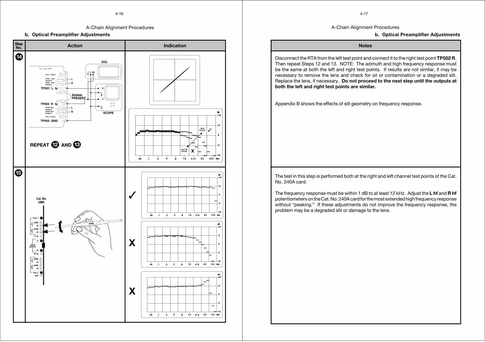
The frequency response must be within 1 dB to at least 12 kHz. Adjust the L hf and R hfpotentiometers on the Cat. No. 240A card for the most extended high frequency responsewithout “peaking.” If these adjustments do not improve the frequency response, theproblem may be a degraded slit or damage to the lens.
Disconnect the RTA from the left test point and connect it to the right test point TP502 R.Then repeat Steps 12 and 13. NOTE: The azimuth and high frequency response mustbe the same at both the left and right test points. If results are not similar, it may benecessary to remove the lens and check for oil or contamination or a degraded slit.Replace the lens, if necessary. Do not proceed to the next step until the outputs atboth the left and right test points are similar.
Appendix B shows the effects of slit geometry on frequency response.
A-Chain Alignment Procedures
StepNo.
4-18
IndicationAction
16
17FOR PROJECTOR NO. 2
REPEAT 1 → 16
Rt
Lt
CAT NO.222
Dolby
Rt
Lt
Lt
Rt
gndProj. 2
hf
GAIN
hf
GAIN
Rt tp
Rt
Lt
Lt tp
Proj. 1
hf
GAIN
hf
GAIN
signalpresent
Cat. No.240A
b. Optical Preamplifier Adjustments
A-Chain Alignment Procedures
Notes
4-19
b. Optical Preamplifier Adjustments
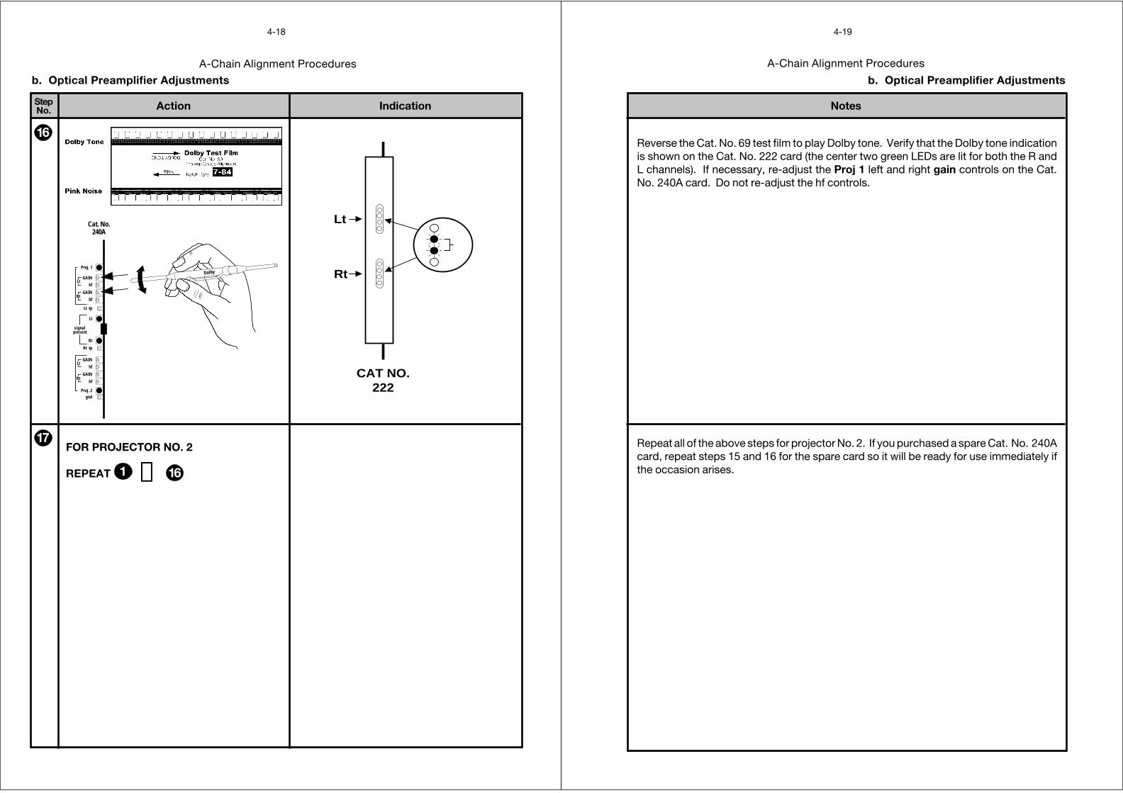
Reverse the Cat. No. 69 test film to play Dolby tone. Verify that the Dolby tone indicationis shown on the Cat. No. 222 card (the center two green LEDs are lit for both the R andL channels). If necessary, re-adjust the Proj 1 left and right gain controls on the Cat.No. 240A card. Do not re-adjust the hf controls.
Repeat all of the above steps for projector No. 2. If you purchased a spare Cat. No. 240Acard, repeat steps 15 and 16 for the spare card so it will be ready for use immediately ifthe occasion arises.
c. Magnetic Preamplifier Adjustments
Magnetic Alignment
The CP65 in its normal configuration does not provide noise reduction for signalsentering through the Magnetic/Aux input. However an optional configuration using Cat.No. 300 SR/A modules in place of the normal Cat. No. 350 SR modules can be used forplaying 70 mm Dolby Stereo prints. To use this option, headers J16, J17 and link J24on the CP65 backplane must be in the correct position. See page 2-8 for informationon the correct positions for J16, J17 and J24.
1. Inspect the magnetic head for evidence of wear. Wear can degrade the frequencyresponse. De-magnetize the head and all elements in the film path, both metal andplastic (some plastic parts may have steel centers). If you have an Annis gauss meteror its equivalent, verify that no elements in the film path are magnetized. Repeat thedegaussing, as required.
2. Inspect the penthouse and perform any mechanical adjustments in accordance withthe manufacturer’s instructions. Verify that all bearings, gears, and guide rollers arein good working order.
3. Install the magnetic preamplifier according to the manufacturer’s information.
4. Connect the magnetic heads to the MPU input barrier strip with high-quality shieldedcable, Belden 8451 or equivalent. Connect the shield at the MPU end only.
5. For a standard CP65 (fitted with Cat. No. 350 SR modules), no A-type noisereduction is provided for magnetic inputs.
• Connect the outputs of the magnetic preamplifier to the“from mpu - no nr” inputs on the TB3 and TB4 barrier strips. See thewiring diagram on page 2-3.
For a CP65-300 (fitted with Cat. No. 300 SR/A modules), A-type noise reduction isprovided for L, C,R,S magnetic inputs.
• Connect the outputs of the magnetic preamplifier to the“from mpu - (format 42)” inputs on TB6 (L,C,R,S) and "fmt 42" inputon TB4 (Le, Re). See the wiring diagram on page 2-4.
6. Place the NORMAL/BYPASS switch in the BYPASS position.
A-Chain Alignment Procedures
4-20
Magnetic Alignment
c. Magnetic Preamplifier Adjustments
7. Remove the Cat. No. 242 card and locate the reversible plug-in Magnetic InputSensitivity header.
100mVin
1V in
The CP65 accepts a nominal operating input level of either 100 mV or 1V — chosenby the position of the reversible plug-in header. The input impedance of the CP65is 100K at both input levels. In addition, some preamplifiers may require atermination resistor (usually 600 ohms). You can connect the termination resistorsat the input barrier strip TB3 and TB4 "from mpu–no nr" terminals on the backplane.Note that changeover between projector 1 and projector 2 must be accomplishedin the magnetic preamplifier.
If noise reduction is to be used for decoding 70 mm Dolby Stereo soundtracks,the header on the Cat. No. 242 B-chain card must be set to the 100 mV position.
If the existing non-Dolby magnetic preamplifiers are used, their compatibility with theCP65 must be ensured.
8. Re-install the Cat. No. 242 card and restore the NORMAL/BYPASS switch to theNORMAL position.
A-Chain Alignment Procedures
4-21

SECTION 5B-CHAIN ALIGNMENT
5-1
B-Chain Alignment Procedures
Action IndicationStepNo.
5-2
a. Setting Room Equalization
NORMAL BYPASS
bypass(switch behind panel)
1
CIN
EM
A E
QU
ALI
ZE
R M
OD
ULE
CA
T. N
o. 6
4BD
olby
Lab
orat
orie
s In
c. S
an F
ranc
isco
and
Lon
don.
L
CIN
EM
A E
QU
ALI
ZE
R M
OD
ULE
CA
T. N
o. 6
4BD
olby
Lab
orat
orie
s In
c. S
an F
ranc
isco
and
Lon
don.
C
CIN
EM
A E
QU
ALI
ZE
R M
OD
ULE
CA
T. N
o. 6
4BD
olby
Lab
orat
orie
s In
c. S
an F
ranc
isco
and
Lon
don.
R2
3
B-Chain Alignment Procedures
Notes
5-3
a. Setting Room Equalization
Open the front panel and place the NORMAL/BYPASS switch in the BYPASS positionso power is removed from the Cat. No. 64 Equalizer modules and the loudspeakers areprotected. The BYPASS LED should be flashing.
Use the labels that are furnished with the CP65 to mark the three Equalizer modules asL, C, and R respectively. The labels make it easy to restore the modules to their correctpositions after they have been removed.
Remove all of the marked Equalizer modules. Remove the shield cover from eachequalizer and verify that all of the equalizer controls are set to the mid-position (12 o’clock).Replace the screws to avoid losing them then plug each of the equalizer modules with itscover removed back into the CP65 in its proper slot.
B-Chain Alignment Procedures
Action IndicationStepNo.
5-4
a. Setting Room Equalization
4
5
Cat. No.85
Cat. No.150
B-Chain Alignment Procedures
Notes
5-5
Remove the Cat. No. 150 Card. Note that when the Cat. No. 150 card is removed, twocard edge connectors are exposed on the backplane and that another slot to theimmediate left of the Cat. No. 150 slot is accessible. This second slot and associatedconnector are for the Cat. No. 85C Pink Noise Generator.
Install the Cat. No. 85C Pink Noise Generator in the special slot to the left of the Cat.No. 150 slot. The switches in the Cat. No. 85C are up or down for ON and center for OFF.The phase is positive when the switches are in the up position and negative in the downposition.
a. Setting Room Equalization
Loudspeakers and Crossovers
Thoroughly check the loudspeakers and power amplifiers for sources of poor performance:
• Check that the loudspeaker cables are in good condition and that they of a suitablegauge for the impedance of the speakers and the length of the run.
• Rattles (a leak in the woofer cabinet may appear to be a rattle).
• Loose bolts or other hardware.
• Open drivers.In systems with pairs of drivers — woofers or tweeters — one of the pair maybe open but the system will still function. Check the speakers with anohmmeter. If one channel requires markedly more equalization than the otheror if one speaker overloads at lower levels than the other speakers, an opendriver circuit could be the cause.
• Missing drivers or other components.
• The settings of the crossovers to match the type of drivers in use and the acousticsof the theater.
The tweeter level control must be set for the best possible frequency responsewith the Cat. No. 64 controls all at mid-point before you attempt any equalization.(The same procedures should be followed if the system uses active crossoverswith bi-amp equipment.) This check should be made with a real time analyzer.
• Phasing between the woofers and tweeters, and between the channels (seeAppendix A).
• Aiming of speakers.Check that the speakers are correctly aimed into the auditorium, and that theyare not obstructed by the screen frame, struts or other obstructions.
B-Chain Alignment Procedures
Action IndicationStepNo.
5-6
a. Setting Room Equalization
5CONT'D
NORMAL BYPASSbypass
(switch behind panel)
6
7
ON
POWER AMP
B-Chain Alignment Procedures
Notes
5-7
Set all the gain controls on all power amplifiers to a known repeatable setting, but do notturn amplifiers on. The preferred setting for the amplifier gain controls is maximum. If adifferent setting is required in order to optimize the noise performance of the system, thecontrols should be locked in position or marked clearly.
Position calibrated microphones in the theatre. Whenever possible use multiplemicrophones and a multiplexer.
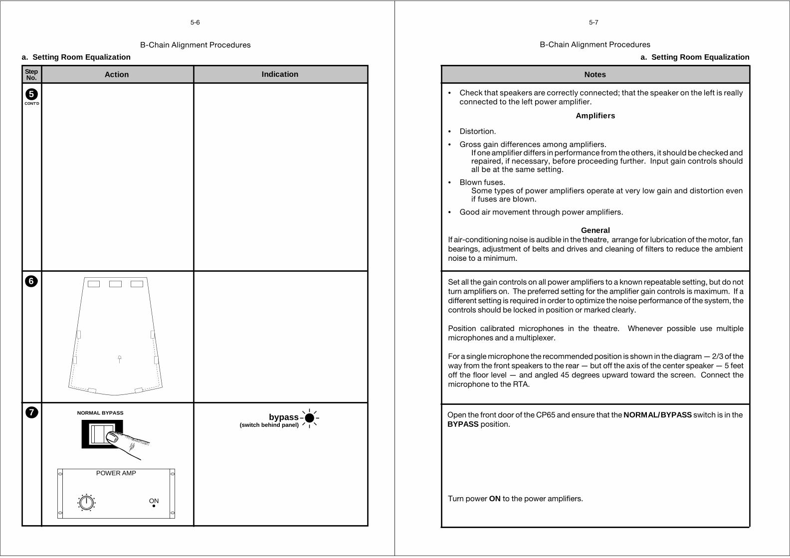
For a single microphone the recommended position is shown in the diagram — 2/3 of theway from the front speakers to the rear — but off the axis of the center speaker — 5 feetoff the floor level — and angled 45 degrees upward toward the screen. Connect themicrophone to the RTA.
a. Setting Room Equalization
• Check that speakers are correctly connected; that the speaker on the left is reallyconnected to the left power amplifier.
Amplifiers
• Distortion.
• Gross gain differences among amplifiers.If one amplifier differs in performance from the others, it should be checked andrepaired, if necessary, before proceeding further. Input gain controls shouldall be at the same setting.
• Blown fuses.Some types of power amplifiers operate at very low gain and distortion evenif fuses are blown.
• Good air movement through power amplifiers.
GeneralIf air-conditioning noise is audible in the theatre, arrange for lubrication of the motor, fanbearings, adjustment of belts and drives and cleaning of filters to reduce the ambientnoise to a minimum.
Turn power ON to the power amplifiers.
Open the front door of the CP65 and ensure that the NORMAL/BYPASS switch is in theBYPASS position.
B-Chain Alignment Procedures
Action IndicationStepNo.
5-8
0
1
2
3
4 5 67
8
9
10
selectlocal/remote
mute
local active
a. Setting Room Equalization
0
1
2
3
4 5 67
8
9
10
NORMAL BYPASS
0
1
2
3
4 5 67
8
9
10
selectlocal/remote
mute
local active
04 Dolby StereoA-type
autosubwoofer
off
CAT. NO. 441
Subwooferoff
8
9
10
11
B-Chain Alignment Procedures
Notes
5-9
a. Setting Room Equalization
Set the FADER to the 0 position.
Verify that the fader local active LED is on. If necessary, press the select local/remoteswitch.
Press the 04 Dolby Stereo A-type switch; the LED in the switch should light.
If a Cat No. 441 Surround Equalizer, Subwoofer card is fitted set thesubwoofer switch to the OFF position.
Set the NORMAL/BYPASS switch to the NORMAL position.
Switch on the center channel pink noise on the Cat. No. 85 Pink Noise Generator (C switchup or down).
Slowly advance the FADER control to position 7. You should hear pink noise.
B-Chain Alignment Procedures
Action IndicationStepNo.
5-10
a. Setting Room Equalization
12
13 → 1211REPEAT
Dolby
gainmono
non-sync
gain
pointstest
mono eq
Ls
R
C
L
Ls
R
C
L
gnd
Ls
R
C
L
R
L
signalpresent
Cat. No.242
Dolby
gainmono
non-sync
gain
pointstest
mono eq
Ls
R
C
L
Ls
R
C
L
gnd
Ls
R
C
L
R
L
signalpresent
Cat. No.242
OFF
80
70
60
50 40 30
75-80 dBC
OFF
80
70
60
50 40 30
75-80 dBC
OFF
80
70
60
50 40 30
75-80 dBC
Dolby
gainmono
non-sync
gain
pointstest
mono eq
Ls
R
C
L
Ls
R
C
L
gnd
Ls
R
C
L
R
L
signalpresent
Cat. No.242
B-Chain Alignment Procedures
Notes
5-11
a. Setting Room Equalization
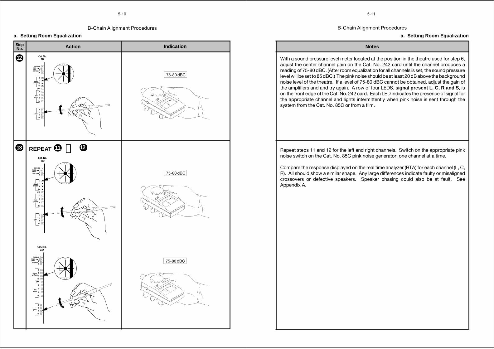
With a sound pressure level meter located at the position in the theatre used for step 6,adjust the center channel gain on the Cat. No. 242 card until the channel produces areading of 75-80 dBC. (After room equalization for all channels is set, the sound pressurelevel will be set to 85 dBC.) The pink noise should be at least 20 dB above the backgroundnoise level of the theatre. If a level of 75-80 dBC cannot be obtained, adjust the gain ofthe amplifiers and and try again. A row of four LEDS, signal present L, C, R and S, ison the front edge of the Cat. No. 242 card. Each LED indicates the presence of signal forthe appropriate channel and lights intermittently when pink noise is sent through thesystem from the Cat. No. 85C or from a film.
Repeat steps 11 and 12 for the left and right channels. Switch on the appropriate pinknoise switch on the Cat. No. 85C pink noise generator, one channel at a time.
Compare the response displayed on the real time analyzer (RTA) for each channel (L, C,R). All should show a similar shape. Any large differences indicate faulty or misalignedcrossovers or defective speakers. Speaker phasing could also be at fault. SeeAppendix A.
B-Chain Alignment Procedures
Action IndicationStepNo.
5-12
a. Setting Room Equalization
bypass(switch behind panel)
NORMAL BYPASS
NORMAL BYPASS
04 Dolby StereoA-type
14
15
.05 .1 .2 .4 .8 1.6 3.15 6.3 12.5 kHz
dB
–10
+5
0
–5
+10
2.0 8.0
B-Chain Alignment Procedures
Notes
5-13
a. Setting Room Equalization
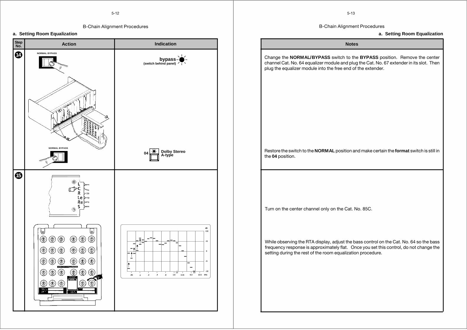
Change the NORMAL/BYPASS switch to the BYPASS position. Remove the centerchannel Cat. No. 64 equalizer module and plug the Cat. No. 67 extender in its slot. Thenplug the equalizer module into the free end of the extender.
Restore the switch to the NORMAL position and make certain the format switch is still inthe 04 position.
Turn on the center channel only on the Cat. No. 85C.
While observing the RTA display, adjust the bass control on the Cat. No. 64 so the bassfrequency response is approximately flat. Once you set this control, do not change thesetting during the rest of the room equalization procedure.
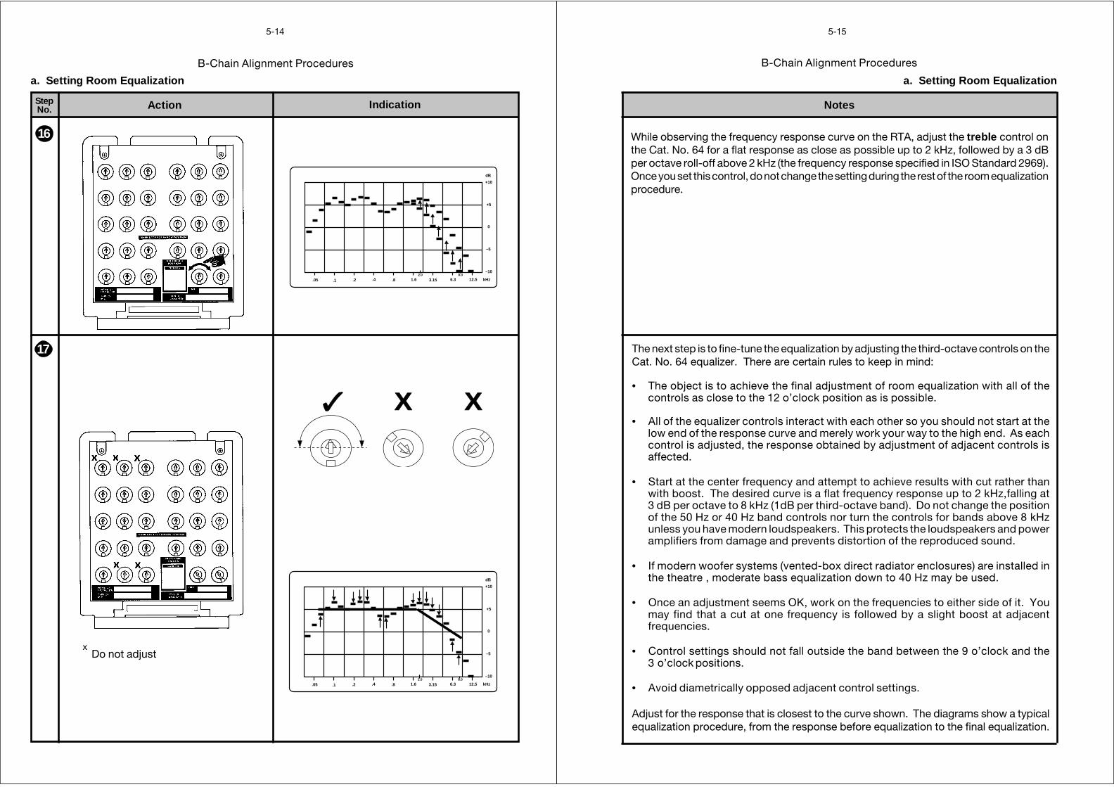
B-Chain Alignment Procedures
Action IndicationStepNo.
5-14
a. Setting Room Equalization
.05 .1 .2 .4 .8 1.6 3.15 6.3 12.5 kHz
dB
–10
+5
0
–5
+10
2.0 8.0
.05 .1 .2 .4 .8 1.6 3.15 6.3 12.5 kHz
dB
–10
+5
0
–5
+10
2.0 8.0
16
✓ X X
17
x Do not adjust
B-Chain Alignment Procedures
Notes
5-15
a. Setting Room Equalization
While observing the frequency response curve on the RTA, adjust the treble control onthe Cat. No. 64 for a flat response as close as possible up to 2 kHz, followed by a 3 dBper octave roll-off above 2 kHz (the frequency response specified in ISO Standard 2969).Once you set this control, do not change the setting during the rest of the room equalizationprocedure.
The next step is to fine-tune the equalization by adjusting the third-octave controls on theCat. No. 64 equalizer. There are certain rules to keep in mind:
• The object is to achieve the final adjustment of room equalization with all of thecontrols as close to the 12 o’clock position as is possible.
• All of the equalizer controls interact with each other so you should not start at thelow end of the response curve and merely work your way to the high end. As eachcontrol is adjusted, the response obtained by adjustment of adjacent controls isaffected.
• Start at the center frequency and attempt to achieve results with cut rather thanwith boost. The desired curve is a flat frequency response up to 2 kHz,falling at3 dB per octave to 8 kHz (1dB per third-octave band). Do not change the positionof the 50 Hz or 40 Hz band controls nor turn the controls for bands above 8 kHzunless you have modern loudspeakers. This protects the loudspeakers and poweramplifiers from damage and prevents distortion of the reproduced sound.
• If modern woofer systems (vented-box direct radiator enclosures) are installed inthe theatre , moderate bass equalization down to 40 Hz may be used.
• Once an adjustment seems OK, work on the frequencies to either side of it. Youmay find that a cut at one frequency is followed by a slight boost at adjacentfrequencies.
• Control settings should not fall outside the band between the 9 o’clock and the3 o’clock positions.
• Avoid diametrically opposed adjacent control settings.
Adjust for the response that is closest to the curve shown. The diagrams show a typicalequalization procedure, from the response before equalization to the final equalization.
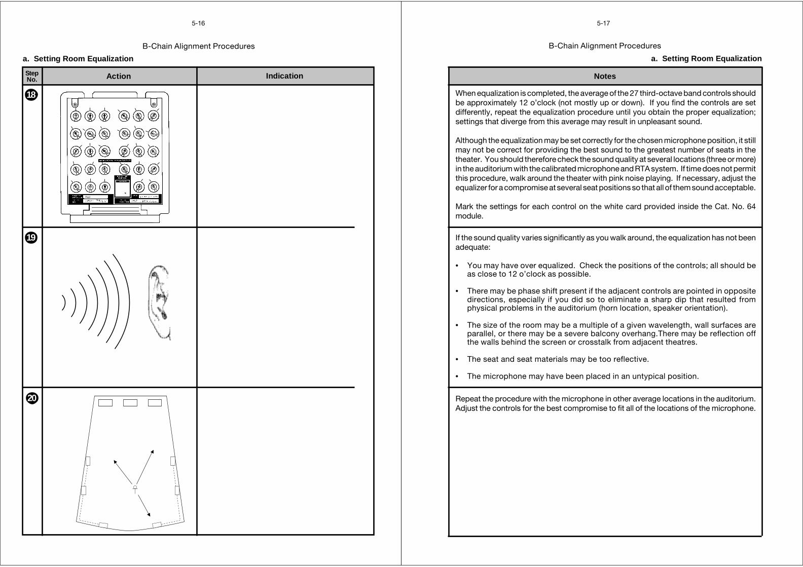
B-Chain Alignment Procedures
Action IndicationStepNo.
5-16
18
19
20
a. Setting Room Equalization
Paul
B-Chain Alignment Procedures
Notes
5-17
a. Setting Room Equalization
When equalization is completed, the average of the 27 third-octave band controls shouldbe approximately 12 o’clock (not mostly up or down). If you find the controls are setdifferently, repeat the equalization procedure until you obtain the proper equalization;settings that diverge from this average may result in unpleasant sound.
Although the equalization may be set correctly for the chosen microphone position, it stillmay not be correct for providing the best sound to the greatest number of seats in thetheater. You should therefore check the sound quality at several locations (three or more)in the auditorium with the calibrated microphone and RTA system. If time does not permitthis procedure, walk around the theater with pink noise playing. If necessary, adjust theequalizer for a compromise at several seat positions so that all of them sound acceptable.
Mark the settings for each control on the white card provided inside the Cat. No. 64module.
If the sound quality varies significantly as you walk around, the equalization has not beenadequate:
• You may have over equalized. Check the positions of the controls; all should beas close to 12 o’clock as possible.
• There may be phase shift present if the adjacent controls are pointed in oppositedirections, especially if you did so to eliminate a sharp dip that resulted fromphysical problems in the auditorium (horn location, speaker orientation).
• The size of the room may be a multiple of a given wavelength, wall surfaces areparallel, or there may be a severe balcony overhang.There may be reflection offthe walls behind the screen or crosstalk from adjacent theatres.
• The seat and seat materials may be too reflective.
• The microphone may have been placed in an untypical position.
Repeat the procedure with the microphone in other average locations in the auditorium.Adjust the controls for the best compromise to fit all of the locations of the microphone.
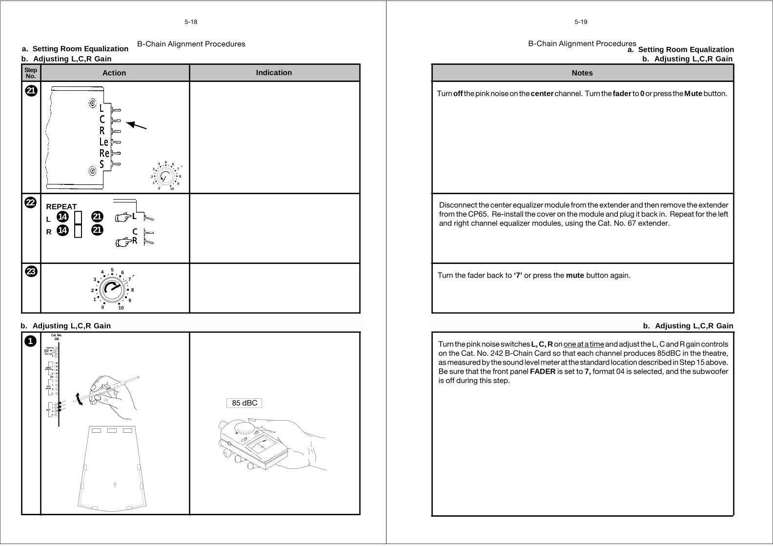
B-Chain Alignment Procedures
Action IndicationStepNo.
5-18
a. Setting Room Equalizationb. Adjusting L,C,R Gain
0
1
2
3
4 5 67
8
9
10
21
22
23
0
1
2
3
4 5 67
8
9
10
b. Adjusting L,C,R Gain
1
REPEAT
L
R
14 →21
14 →21
Dolby
gainmono
non-sync
gain
pointstest
mono eq
Ls
R
C
L
Ls
R
C
L
gnd
Ls
R
C
L
R
L
signalpresent
Cat. No.242
OFF
80
70
60
50 40 30
85 dBC
B-Chain Alignment Procedures
Notes
5-19
Turn off the pink noise on the center channel. Turn the fader to 0 or press the Mute button.
a. Setting Room Equalizationb. Adjusting L,C,R Gain
b. Adjusting L,C,R Gain
Turn the pink noise switches L, C, R on one at a time and adjust the L, C and R gain controlson the Cat. No. 242 B-Chain Card so that each channel produces 85dBC in the theatre,as measured by the sound level meter at the standard location described in Step 15 above.Be sure that the front panel FADER is set to 7, format 04 is selected, and the subwooferis off during this step.
Turn the fader back to ‘7’ or press the mute button again.
Disconnect the center equalizer module from the extender and then remove the extenderfrom the CP65. Re-install the cover on the module and plug it back in. Repeat for the leftand right channel equalizer modules, using the Cat. No. 67 extender.
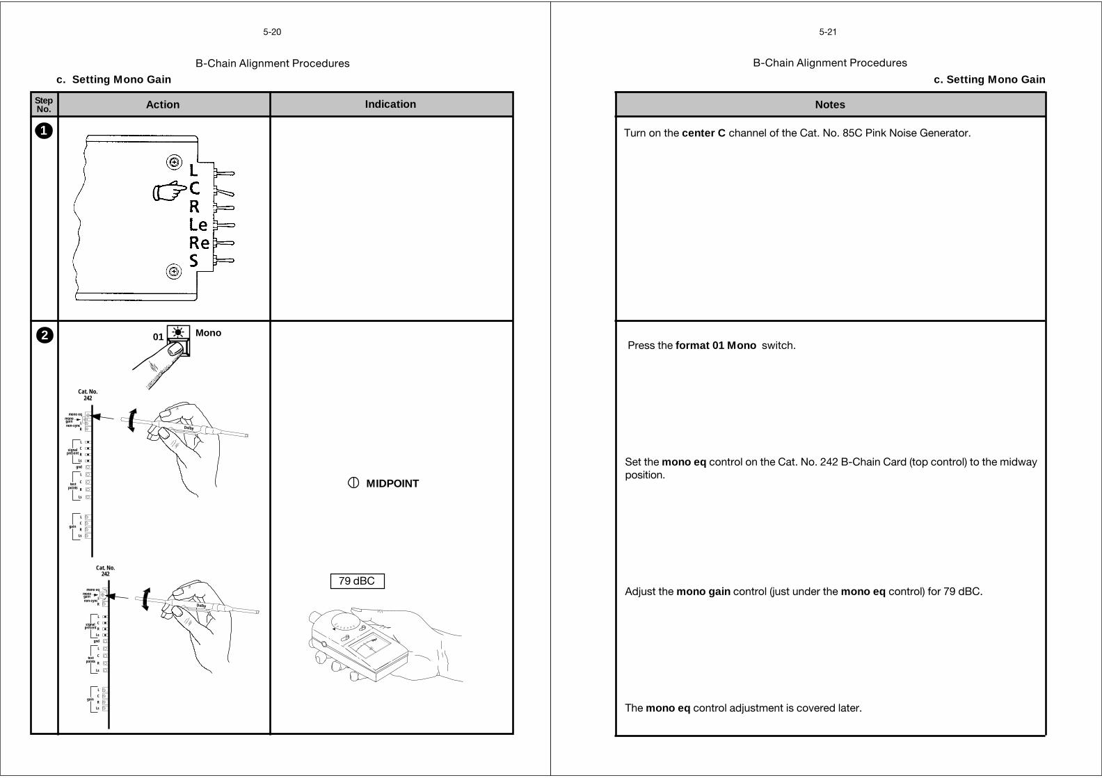
B-Chain Alignment Procedures
Action IndicationStepNo.
5-20
Dolby
gainmono
non-sync
gain
pointstest
mono eq
Ls
R
C
L
Ls
R
C
L
gnd
Ls
R
C
L
R
L
signalpresent
Cat. No.242
c. Setting Mono Gain
1
MIDPOINT
2 01 Mono
Dolby
gainmono
non-sync
gain
pointstest
mono eq
Ls
R
C
L
Ls
R
C
L
gnd
Ls
R
C
L
R
L
signalpresent
Cat. No.242
OFF
80
70
60
50 40 30
79 dBC
B-Chain Alignment Procedures
Notes
5-21
c. Setting Mono Gain
Turn on the center C channel of the Cat. No. 85C Pink Noise Generator.
Press the format 01 Mono switch.
Set the mono eq control on the Cat. No. 242 B-Chain Card (top control) to the midwayposition.
Adjust the mono gain control (just under the mono eq control) for 79 dBC.
The mono eq control adjustment is covered later.
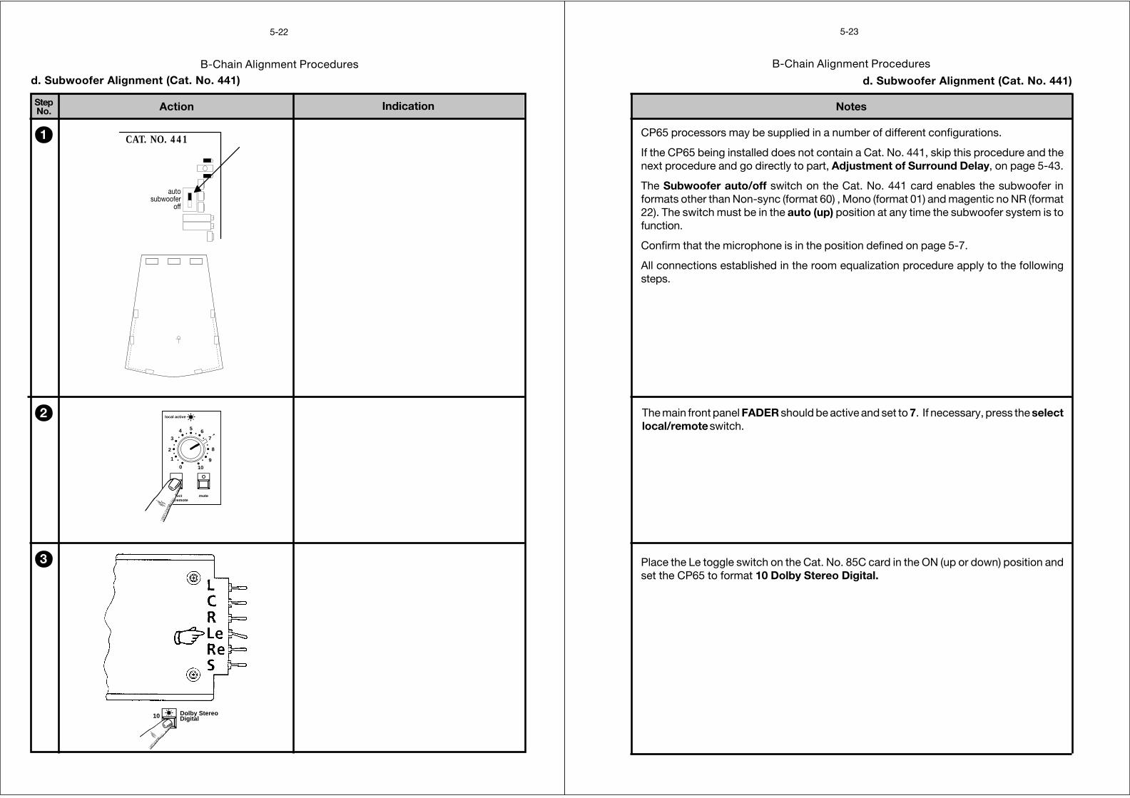
B-Chain Alignment Procedures
Action IndicationStepNo.
5-22
0
1
2
3
4 5 67
8
9
10
selectlocal/remote
mute
local active
autosubwoofer
off
CAT. NO. 4411
2
3
d. Subwoofer Alignment (Cat. No. 441)
10 Dolby StereoDigital
B-Chain Alignment Procedures
Notes
5-23
d. Subwoofer Alignment (Cat. No. 441)
CP65 processors may be supplied in a number of different configurations.
If the CP65 being installed does not contain a Cat. No. 441, skip this procedure and thenext procedure and go directly to part, Adjustment of Surround Delay, on page 5-43.
The Subwoofer auto/off switch on the Cat. No. 441 card enables the subwoofer informats other than Non-sync (format 60) , Mono (format 01) and magentic no NR (format22). The switch must be in the auto (up) position at any time the subwoofer system is tofunction.
Confirm that the microphone is in the position defined on page 5-7.
All connections established in the room equalization procedure apply to the followingsteps.
The main front panel FADER should be active and set to 7. If necessary, press the selectlocal/remote switch.
Place the Le toggle switch on the Cat. No. 85C card in the ON (up or down) position andset the CP65 to format 10 Dolby Stereo Digital.
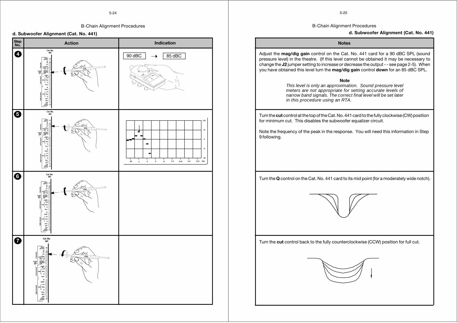
B-Chain Alignment Procedures
Action IndicationStepNo.
5-24
4
5
6
7
d. Subwoofer Alignment (Cat. No. 441)
Dolby
n-syncsurrgain
Q
on
presentsignal
gndgainbass
Q
mid freq
cut
treble
tp
bass
Q
freqmid
cut
treble
gainmag/digopt gain
offauto freq
cut
tppresent
signal
Subw
oofe
rLe
ft Su
rrou
ndRi
ght S
urro
und
Cat. No.441
Dolby
n-syncsurrgain
Q
on
presentsignal
gndgainbass
Q
mid freq
cut
treble
tp
bass
Q
freqmid
cut
treble
gainmag/digopt gain
offauto freq
cut
tppresent
signal
Subw
oofe
rLe
ft Su
rrou
ndRi
ght S
urro
und
Cat. No.441
Dolby
n-syncsurrgain
Q
on
presentsignal
gndgainbass
Q
mid freq
cut
treble
tp
bass
Q
freqmid
cut
treble
gainmag/digopt gain
offauto freq
cut
tppresent
signal
Subw
oofe
rLe
ft Su
rrou
ndRi
ght S
urro
und
Cat. No.441
90 dBC 85 dBC➝
Dolbyn-sync
surrgain
Q
on
presentsignal
gndgainbass
Q
mid freq
cut
treble
tp
bass
Q
freqmid
cut
treble
gainmag/digopt gain
offauto freq
cut
tppresent
signal
Subw
oofe
rLe
ft Su
rrou
ndRi
ght S
urro
und
Cat. No.441
OFF
80
70
60
50 40 30
.05 .1 .2 .4 .8 1.6 3.15 6.3 12.5 kHz
dB
–10
+5
0
–5
+10
B-Chain Alignment Procedures
Notes
5-25
d. Subwoofer Alignment (Cat. No. 441)
Adjust the mag/dig gain control on the Cat. No. 441 card for a 90 dBC SPL (soundpressure level) in the theatre. (If this level cannot be obtained it may be necessary tochange the J2 jumper setting to increase or decrease the output - - see page 2-5). Whenyou have obtained this level turn the mag/dig gain control down for an 85 dBC SPL.
NoteThis level is only an approximation. Sound pressure levelmeters are not appropriate for setting accurate levels ofnarrow band signals. The correct final level will be set laterin this procedure using an RTA.
Turn the cut control at the top of the Cat. No. 441 card to the fully clockwise (CW) positionfor minimum cut. This disables the subwoofer equalizer circuit.
Note the frequency of the peak in the response. You will need this information in Step9 following.
Turn the Q control on the Cat. No. 441 card to its mid point (for a moderately wide notch).
Turn the cut control back to the fully counterclockwise (CCW) position for full cut.
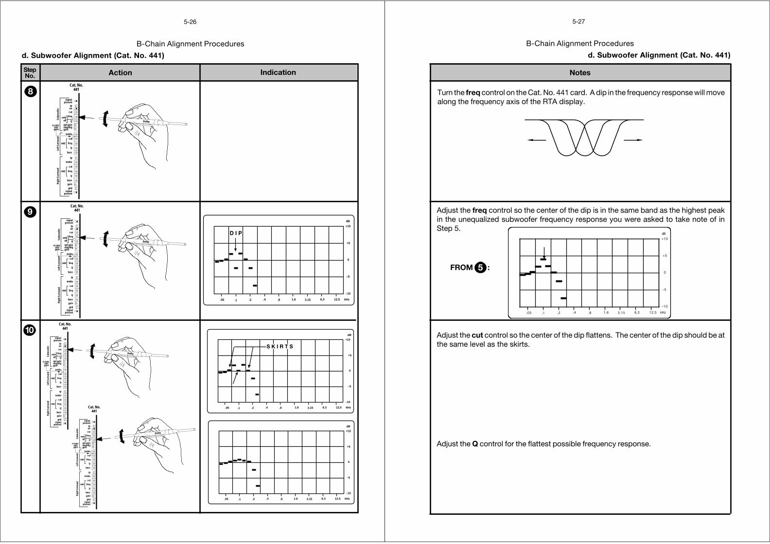
B-Chain Alignment Procedures
Action IndicationStepNo.
5-26
8
9
10
d. Subwoofer Alignment (Cat. No. 441)
Dolbyn-sync
surrgain
Q
on
presentsignal
gndgainbass
Q
mid freq
cut
treble
tp
bass
Q
freqmid
cut
treble
gainmag/digopt gain
offauto freq
cut
tppresent
signal
Subw
oofe
rLe
ft Su
rrou
ndRi
ght S
urro
und
Cat. No.441
Dolbyn-sync
surrgain
Q
on
presentsignal
gndgainbass
Q
mid freq
cut
treble
tp
bass
Q
freqmid
cut
treble
gainmag/digopt gain
offauto freq
cut
tppresent
signal
Subw
oofe
rLe
ft Su
rrou
ndRi
ght S
urro
und
Cat. No.441
Dolby
n-syncsurrgain
Q
on
presentsignal
gndgainbass
Q
mid freq
cut
treble
tp
bass
Q
freqmid
cut
treble
gainmag/digopt gain
offauto freq
cut
tppresent
signal
Subw
oofe
rLe
ft Su
rrou
ndRi
ght S
urro
und
Cat. No.441
Dolby
n-syncsurrgain
Q
on
presentsignal
gndgainbass
Q
mid freq
cut
treble
tp
bass
Q
freqmid
cut
treble
gainmag/digopt gain
offauto freq
cut
tppresent
signal
Subw
oofe
rLe
ft Su
rrou
ndRi
ght S
urro
und
Cat. No.441
.05 .1 .2 .4 .8 1.6 3.15 6.3 12.5 kHz
dB
–10
+5
0
–5
+10
D I P
.05 .1 .2 .4 .8 1.6 3.15 6.3 12.5 kHz
dB
–10
+5
0
–5
+10
S K I R T S
.05 .1 .2 .4 .8 1.6 3.15 6.3 12.5 kHz
dB
–10
+5
0
–5
+10
B-Chain Alignment Procedures
Notes
5-27
d. Subwoofer Alignment (Cat. No. 441)
Turn the freq control on the Cat. No. 441 card. A dip in the frequency response will movealong the frequency axis of the RTA display.
Adjust the cut control so the center of the dip flattens. The center of the dip should be atthe same level as the skirts.
Adjust the Q control for the flattest possible frequency response.
Adjust the freq control so the center of the dip is in the same band as the highest peakin the unequalized subwoofer frequency response you were asked to take note of inStep 5.
5FROM :
.05 .1 .2 .4 .8 1.6 3.15 6.3 12.5 kHz
dB
–10
+5
0
–5
+10
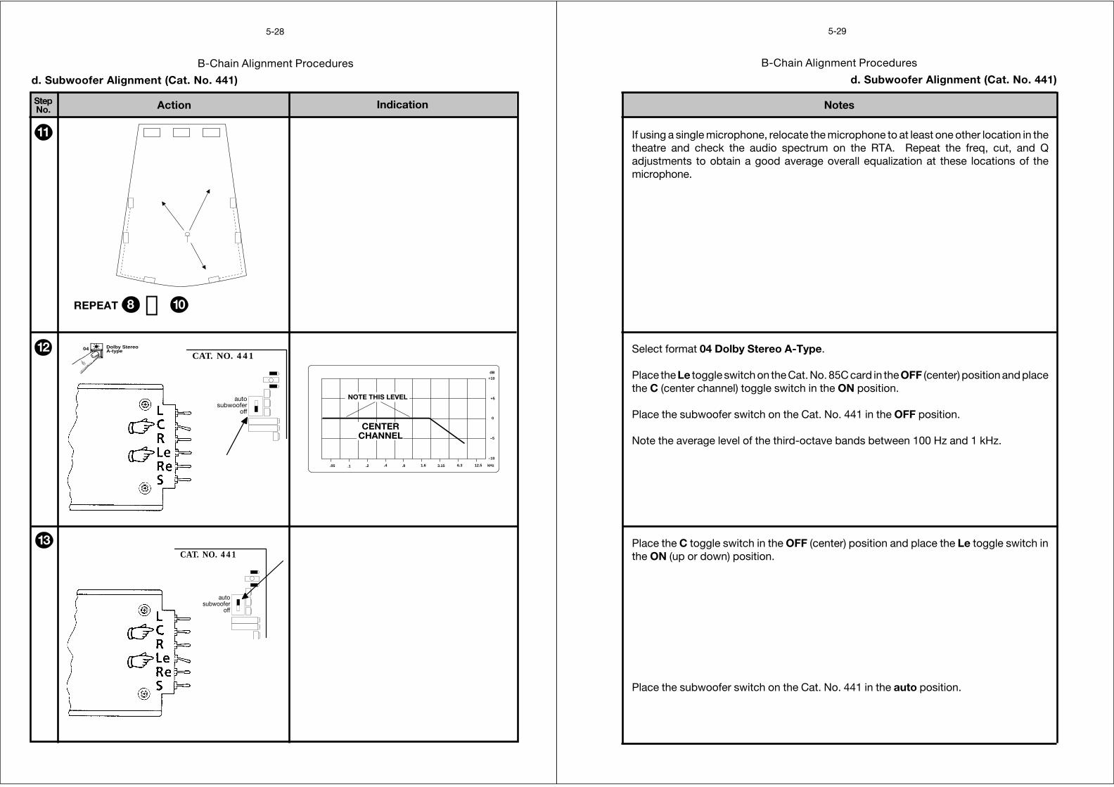
B-Chain Alignment Procedures
Action IndicationStepNo.
5-28
.05 .1 .2 .4 .8 1.6 3.15 6.3 12.5 kHz
dB
–10
+5
0
–5
+10
CENTERCHANNEL
NOTE THIS LEVEL
11
112
autosubwoofer
off
CAT. NO. 44113
d. Subwoofer Alignment (Cat. No. 441)
REPEAT →8 10
autosubwoofer
off
CAT. NO. 44104 Dolby Stereo
A-type
B-Chain Alignment Procedures
Notes
5-29
d. Subwoofer Alignment (Cat. No. 441)
If using a single microphone, relocate the microphone to at least one other location in thetheatre and check the audio spectrum on the RTA. Repeat the freq, cut, and Qadjustments to obtain a good average overall equalization at these locations of themicrophone.
Select format 04 Dolby Stereo A-Type.
Place the Le toggle switch on the Cat. No. 85C card in the OFF (center) position and placethe C (center channel) toggle switch in the ON position.
Place the subwoofer switch on the Cat. No. 441 in the OFF position.
Note the average level of the third-octave bands between 100 Hz and 1 kHz.
Place the C toggle switch in the OFF (center) position and place the Le toggle switch inthe ON (up or down) position.
Place the subwoofer switch on the Cat. No. 441 in the auto position.
B-Chain Alignment Procedures
Action IndicationStepNo.
5-30
.05 .1 .2 .4 .8 1.6 3.15 6.3 12.5 kHz
dB
–10
+5
0
–5
+10
.05 .1 .2 .4 .8 1.6 3.15 6.3 12.5 kHz
dB
–10
+5
0
–5
+10
14
d. Subwoofer Alignment (Cat. No. 441)
15
Dolby
n-syncsurrgain
Q
on
presentsignal
gndgainbass
Q
mid freq
cut
treble
tp
bass
Q
freqmid
cut
treble
gainmag/digopt gain
offauto freq
cut
tppresent
signal
Subw
oofe
rLe
ft Su
rrou
ndRi
ght S
urro
und
Cat. No.441
10 Dolby StereoDigital
Dolbyn-sync
surrgain
Q
on
presentsignal
gndgainbass
Q
mid freq
cut
treble
tp
bass
Q
freqmid
cut
treble
gainmag/digopt gain
offauto freq
cut
tppresent
signal
Subw
oofe
rLe
ft Su
rrou
ndRi
ght S
urro
und
Cat. No.441
16
.05 .1 .2 .4 .8 1.6 3.15 6.3 12.5 kHz
dB
–10
+5
0
–5
+10
+10 dB
.05 .1 .2 .4 .8 1.6 3.15 6.3 12.5 kHz
dB
–10
+5
0
–5
+10
.05 .1 .2 .4 .8 1.6 3.15 6.3 12.5 kHz
dB
–10
+5
0
–5
+10
autosubwoofer
off
autosubwoofer
off
112SAME AS
B-Chain Alignment Procedures
Notes
5-31
d. Subwoofer Alignment (Cat. No. 441)
Adjust the optical gain control on the Cat. No. 441 card so that the average level of thebands from the subwoofer is at the same level on the analyzer screen as you noted forthe center channel in the previous step.
Place the Le toggle switch on the Cat. No. 85C card in the OFF (center) position andplace the C (center channel) toggle switch in the ON position.
Note the change in the average level of the bands from 20 Hz to 100 Hz when thesubwoofer switch on the Cat. No. 441 is switched between OFF and AUTO. Thereshould be a level INCREASE when it is switched to AUTO. The subwoofer is out ofphase with the front channels if you do not see this level increase. Reverse thesubwoofer(s) speaker connections.
Re-select Format 10.
Adjust the mag/dig gain on the Cat. No. 441 so that the level of the bands from thesubwoofer increases 10 dB above the level in the previous step.
The subwoofer alignment is completed.
B-Chain Alignment Procedures
Action IndicationStepNo.
5-32
e. Surround Equalization Alignment (Cat. No. 441)
1
2
OFF
RIGHT
3
85 dBC
STEREO SURROUND
88 dBC
MONO SURROUND
Dolby
gainmono
non-sync
gain
pointstest
mono eq
Ls
R
C
L
Ls
R
C
L
gnd
Ls
R
C
L
R
L
signalpresent
Cat. No.242
04 Dolby StereoA-type
OFF
80
70
60
50 40 30
ReS
B-Chain Alignment Procedures
Notes
5-33
e. Surround Equalization Alignment (Cat. No. 441)
If your CP65 does not contain the Cat. No. 441 Surround Equalizer and Subwoofer Card,skip this paragraph and go directly to page 5-42, Adjustment of Surround Delay. TheCP65 will function without the Cat. No. 441 card, but the surround frequency responsecannot be equalized.
The surround equalizer on the Cat. No. 441 card consists of:
• A parametric mid-band section with variable cut, bandwidth, and center frequency.
• Shelving type Bass and Treble controls.
All connections established in the previous procedure still apply to the surround equalizationalignment. Confirm that the microphone is in the position defined on page 5.6. Ensurethat format 04 is selected.
Note: The Cat. No. 441 can be configured for either Mono or Stereo surround operation using linkJ3 ( See page 2-5 for details). If Mono operation is selected then an identical signal will be fedto both Ls and Rs outputs in all formats. If only one power amplifier is to be used for the surroundchannel then the Ls should be used. If more than one surround amplifier is to be used, bothoutputs may be used to feed, for example, balcony and ground floor. The separate level controlsand equalizers may then be used to compensate for differences caused by the different acousticenvironments of the two areas. If stereo operation is selected a stereo surround signal will be fedto the surround channels when format 10, Dolby Stereo SR•D is selected.
If the surround speakers are wired for stereo operation or both surround outputs are in useswitch off (or disconnect the input to) the right surround amplifier or amplifiers.
Turn on the S switch on the Cat. No. 85C pink noise generator. Be sure that format 04is selected.
Adjust the Ls ( left surround) gain control on the Cat. No. 242 B-Chain card for a soundpressure level of approximately 85 dBC in the theatre. If only one surround output is usedset the level to 88 dBC.
Action IndicationStepNo.
5-34
B-Chain Alignment Procedures
e. Surround Equalization Alignment (Cat. No. 441)
3
5
4
Dolby
n-syncsurrgain
Q
on
presentsignal
gndgainbass
Q
mid freq
cut
treble
tp
bass
Q
freqmid
cut
treble
gainmag/digopt gain
offauto freq
cut
tppresent
signal
Subw
oofe
rLe
ft Su
rrou
ndRi
ght S
urro
und
Cat. No.441
Dolby
n-syncsurrgain
Q
on
presentsignal
gndgainbass
Q
mid freq
cut
treble
tp
bass
Q
freqmid
cut
treble
gainmag/digopt gain
offauto freq
cut
tppresent
signal
Subw
oofe
rLe
ft Su
rrou
ndRi
ght S
urro
und
Cat. No.441
Dolby
n-syncsurrgain
Q
on
presentsignal
gndgainbass
Q
mid freq
cut
treble
tp
bass
Q
freqmid
cut
treble
gainmag/digopt gain
offauto freq
cut
tppresent
signal
Subw
oofe
rLe
ft Su
rrou
ndRi
ght S
urro
und
Cat. No.441
.05 .1 .2 .4 .8 1.6 3.15 6.3 12.5 kHz
dB
–10
+5
0
–5
+10
NOTE
.05 .1 .2 .4 .8 1.6 3.15 6.3 12.5 kHz
dB
–10
+5
0
–5
+10
B-Chain Alignment Procedures
Notes
5-35
e. Surround Equalization Alignment (Cat. No. 441)
Adjust the Left Surround bass control on the Cat. No. 441 card for as flat as possiblelow frequency response on the RTA. Use caution when adjusting the bass control; manysurround loudspeaker systems are deficient in their low frequency response. Attempts toboost the output of such system beyond their capabilities simply wastes amplifier powerand can result in distortion and possibly damage to the surround loudspeakers.
Turn the Cut control fully counterclockwise and note the position of the notch producedby the equalizer.
Adjust the Left Surround treble control to its mid point, so that it provides neither cutnor boost.
Adjust the mid frequency controls as follows: Turn the Cut control fully clockwise (CW).Set the Q and freq controls to their mid positions.
Note the position of the center of the highest frequency peak in the 350 Hz to 3 kHz regionon the analyzer screen.
Action IndicationStepNo.
5-36
B-Chain Alignment Procedures
e. Surround Equalization Alignment (Cat. No. 441)
6
9 REPEAT 6 → 8
8
7
Dolby
n-syncsurrgain
Q
on
presentsignal
gndgainbass
Q
mid freq
cut
treble
tp
bass
Q
freqmid
cut
treble
gainmag/digopt gain
offauto freq
cut
tppresent
signal
Subw
oofe
rLe
ft Su
rrou
ndRi
ght S
urro
und
Cat. No.441
Dolby
n-syncsurrgain
Q
on
presentsignal
gndgainbass
Q
mid freq
cut
treble
tp
bass
Q
freqmid
cut
treble
gainmag/digopt gain
offauto freq
cut
tppresent
signal
Subw
oofe
rLe
ft Su
rrou
ndRi
ght S
urro
und
Cat. No.441
Dolbyn-syncsurrgain
Q
on
presentsignal
gndgainbass
Q
mid freq
cut
treble
tp
bass
Q
freqmid
cut
treble
gainmag/digopt gain
offauto freq
cut
tppresent
signal
Subw
oofe
rLe
ft Su
rrou
ndRi
ght S
urro
und
Cat. No.441
.05 .1 .2 .4 .8 1.6 3.15 6.3 12.5 kHz
dB
–10
+5
0
–5
+10
D I P
.05 .1 .2 .4 .8 1.6 3.15 6.3 12.5 kHz
dB
–10
+5
0
–5
+10
.05 .1 .2 .4 .8 1.6 3.15 6.3 12.5 kHz
dB
–10
+5
0
–5
+10
DESIREDRESPONSE
B-Chain Alignment Procedures
Notes
5-37
e. Surround Equalization Alignment (Cat. No. 441)
Turn the freq control so that the notch is located over the peak noted in the previous step.
The treble and mid equalizer controls interact. Repeat the adjustments until no furtheradjustment is required and you have attained the optimum frequency response.
Adjust the treble control on the Cat. No. 441 card for the best approximation to the desiredresponse shown.
Adjust the Cut and Q controls for the flattest response in this part of the spectrum.
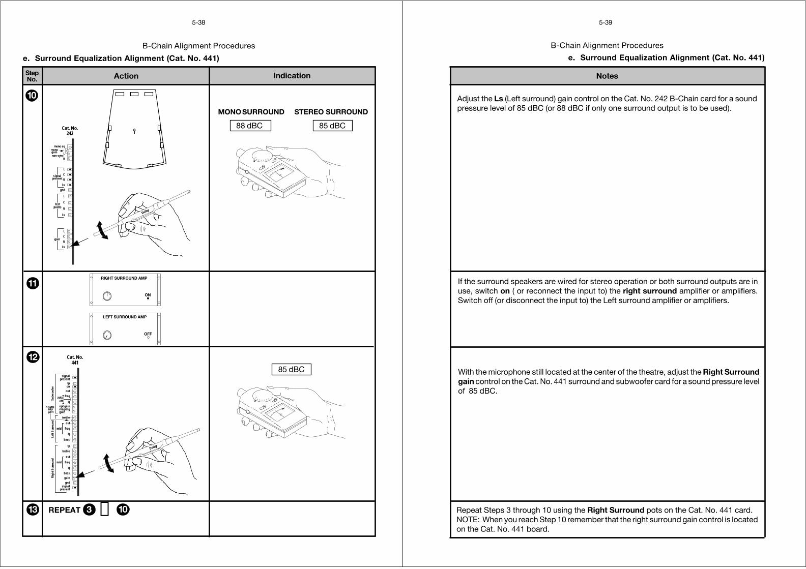
Action IndicationStepNo.
5-38
B-Chain Alignment Procedures
85 dBC
STEREO SURROUND
88 dBC
MONO SURROUND
e. Surround Equalization Alignment (Cat. No. 441)
10
113 REPEAT 3 →10
11285 dBC
Dolby
n-syncsurrgain
Q
on
presentsignal
gndgainbass
Q
mid freq
cut
treble
tp
bass
Q
freqmid
cut
treble
gainmag/digopt gain
offauto freq
cut
tppresent
signal
Subw
oofe
rLe
ft Su
rrou
ndRi
ght S
urro
und
Cat. No.441
ON
RIGHT SURROUND AMP
OFF
LEFT SURROUND AMP
11
Dolby
gainmono
non-sync
gain
pointstest
mono eq
Ls
R
C
L
Ls
R
C
L
gnd
Ls
R
C
L
R
L
signalpresent
Cat. No.242
OFF
80
70
60
50 40 30
OFF
80
70
60
50 40 30
B-Chain Alignment Procedures
Notes
5-39
e. Surround Equalization Alignment (Cat. No. 441)
Adjust the Ls (Left surround) gain control on the Cat. No. 242 B-Chain card for a soundpressure level of 85 dBC (or 88 dBC if only one surround output is to be used).
Repeat Steps 3 through 10 using the Right Surround pots on the Cat. No. 441 card.NOTE: When you reach Step 10 remember that the right surround gain control is locatedon the Cat. No. 441 board.
With the microphone still located at the center of the theatre, adjust the Right Surroundgain control on the Cat. No. 441 surround and subwoofer card for a sound pressure levelof 85 dBC.
If the surround speakers are wired for stereo operation or both surround outputs are inuse, switch on ( or reconnect the input to) the right surround amplifier or amplifiers.Switch off (or disconnect the input to) the Left surround amplifier or amplifiers.
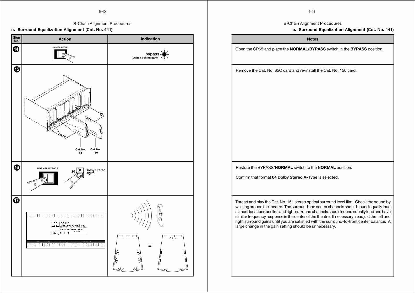
Action IndicationStepNo.
5-40
B-Chain Alignment Procedures
=
17
e. Surround Equalization Alignment (Cat. No. 441)
16
bypass(switch behind panel)
NORMAL BYPASS
14
15
10 Dolby StereoDigital
NORMAL BYPASS
Cat. No.150
Cat. No.85
B-Chain Alignment Procedures
Notes
5-41
e. Surround Equalization Alignment (Cat. No. 441)
Thread and play the Cat. No. 151 stereo optical surround level film. Check the sound bywalking around the theatre. The surround and center channels should sound equally loudat most locations and left and right surround channels should sound equally loud and havesimilar frequency response in the center of the theatre. If necessary, readjust the left andright surround gains until you are satisfied with the surround-to-front center balance. Alarge change in the gain setting should be unnecessary.
Restore the BYPASS/NORMAL switch to the NORMAL position.
Confirm that format 04 Dolby Stereo A-Type is selected.
Open the CP65 and place the NORMAL/BYPASS switch in the BYPASS position.
Remove the Cat. No. 85C card and re-install the Cat. No. 150 card.
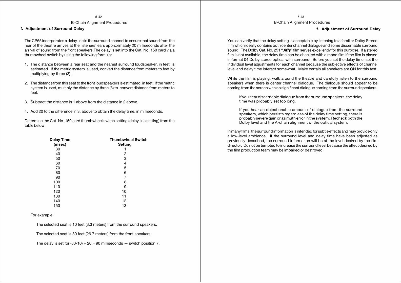
f. Adjustment of Surround Delay
5-42
B-Chain Alignment Procedures
The CP65 incorporates a delay line in the surround channel to ensure that sound from therear of the theatre arrives at the listeners’ ears approximately 20 milliseconds after thearrival of sound from the front speakers.The delay is set into the Cat. No. 150 card via athumbwheel switch by using the following formula:
1. The distance between a rear seat and the nearest surround loudspeaker, in feet, isestimated. If the metric system is used, convert the distance from meters to feet bymultiplying by three (3).
2. The distance from this seat to the front loudspeakers is estimated, in feet. If the metricsystem is used, multiply the distance by three (3) to convert distance from meters tofeet.
3. Subtract the distance in 1 above from the distance in 2 above.
4. Add 20 to the difference in 3. above to obtain the delay time, in milliseconds.
Determine the Cat. No. 150 card thumbwheel switch setting (delay line setting) from thetable below.
Delay Time Thumbwheel Switch(msec) Setting30 140 250 360 470 580 690 7
100 8110 9120 10130 11140 12150 13
For example:
The selected seat is 10 feet (3.3 meters) from the surround speakers.
The selected seat is 80 feet (26.7 meters) from the front speakers.
The delay is set for (80-10) + 20 = 90 milliseconds — switch position 7.
f. Adjustment of Surround Delay
5-43
B-Chain Alignment Procedures
You can verify that the delay setting is acceptable by listening to a familiar Dolby Stereofilm which ideally contains both center channel dialogue and some discernable surroundsound. The Dolby Cat. No. 251 “Jiffy” film serves excellently for this purpose. If a stereofilm is not available, the delay time can be checked with a mono film if the film is playedin format 04 Dolby stereo optical with surround. Before you set the delay time, set theindividual level adjustments for each channel because the subjective effects of channellevel and delay time interact somewhat. Make certain all speakers are ON for this test.
While the film is playing, walk around the theatre and carefully listen to the surroundspeakers when there is center channel dialogue. The dialogue should appear to becoming from the screen with no significant dialogue coming from the surround speakers.
If you hear discernable dialogue from the surround speakers, the delaytime was probably set too long.
If you hear an objectionable amount of dialogue from the surroundspeakers, which persists regardless of the delay time setting, there isprobably severe gain or azimuth error in the system. Recheck both theDolby level and the A-chain alignment of the optical system.
In many films, the surround information is intended for subtle effects and may provide onlya low-level ambience. If the surround level and delay time have been adjusted aspreviously described, the surround information will be at the level desired by the filmdirector. Do not be tempted to increase the surround level because the effect desired bythe film production team may be impaired or destroyed.
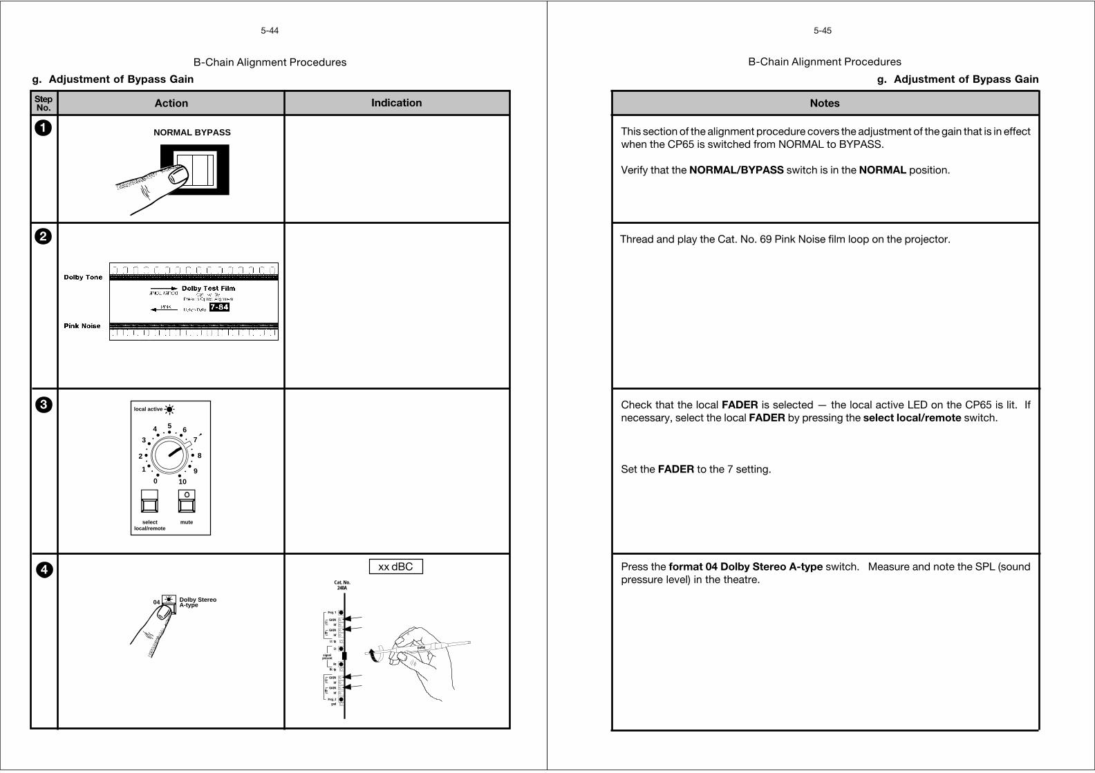
Action IndicationStepNo.
5-44
B-Chain Alignment Procedures
g. Adjustment of Bypass Gain
NORMAL BYPASS1
2
3
4
0
1
2
3
4 5 67
8
9
10
selectlocal/remote
mute
local active
xx dBC
04 Dolby StereoA-type
Dolby
Rt
Lt
Lt
Rt
gndProj. 2
hf
GAIN
hf
GAIN
Rt tp
Rt
Lt
Lt tp
Proj. 1
hf
GAIN
hf
GAIN
signalpresent
Cat. No.240A
B-Chain Alignment Procedures
Notes
5-45
g. Adjustment of Bypass Gain
Check that the local FADER is selected — the local active LED on the CP65 is lit. Ifnecessary, select the local FADER by pressing the select local/remote switch.
Set the FADER to the 7 setting.
Thread and play the Cat. No. 69 Pink Noise film loop on the projector.
This section of the alignment procedure covers the adjustment of the gain that is in effectwhen the CP65 is switched from NORMAL to BYPASS.
Verify that the NORMAL/BYPASS switch is in the NORMAL position.
Press the format 04 Dolby Stereo A-type switch. Measure and note the SPL (soundpressure level) in the theatre.
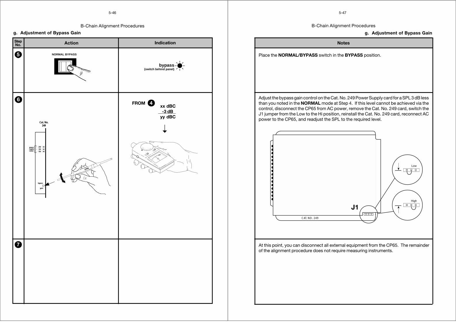
Action IndicationStepNo.
5-46
B-Chain Alignment Procedures
NORMAL BYPASS
bypass(switch behind panel)
g. Adjustment of Bypass Gain
6
7
5
Dolby
15V15V24V
gain
bypass
statussupplypower
Cat. No.249
OFF
80
70
60
50 40 30
xx dBC-3 dB
yy dBC
FROM 4
➝
B-Chain Alignment Procedures
Notes
5-47
g. Adjustment of Bypass Gain
Place the NORMAL/BYPASS switch in the BYPASS position.
Adjust the bypass gain control on the Cat. No. 249 Power Supply card for a SPL 3 dB lessthan you noted in the NORMAL mode at Step 4. If this level cannot be achieved via thecontrol, disconnect the CP65 from AC power, remove the Cat. No. 249 card, switch theJ1 jumper from the Low to the Hi position, reinstall the Cat. No. 249 card, reconnect ACpower to the CP65, and readjust the SPL to the required level.
CAT. NO. 249
Low
High
At this point, you can disconnect all external equipment from the CP65. The remainderof the alignment procedure does not require measuring instruments.
J1
Action IndicationStepNo.
5-48
B-Chain Alignment Procedures
60 non-sync
1
4
2
4
3
NORMAL BYPASS
0
1
2
3
4 5 67
8
9
10
selectlocal/remote
mute
local active
h. Adjustment of Non-sync Gain
B-Chain Alignment Procedures
Notes
5-49
h. Adjustment of Non-sync Gain
Connect a cassette deck or CD player to the from non sync terminals on terminal blockTB1 on the backplane of the CP65.
Press the format 60 non sync switch.
Place the NORMAL/BYPASS switch in the NORMAL position.
Set the FADER to the 7 setting.
Check that the local FADER is selected — the local active LED on the CP65 is lit. Ifnecessary, select the local FADER by pressing the select local/remote switch.
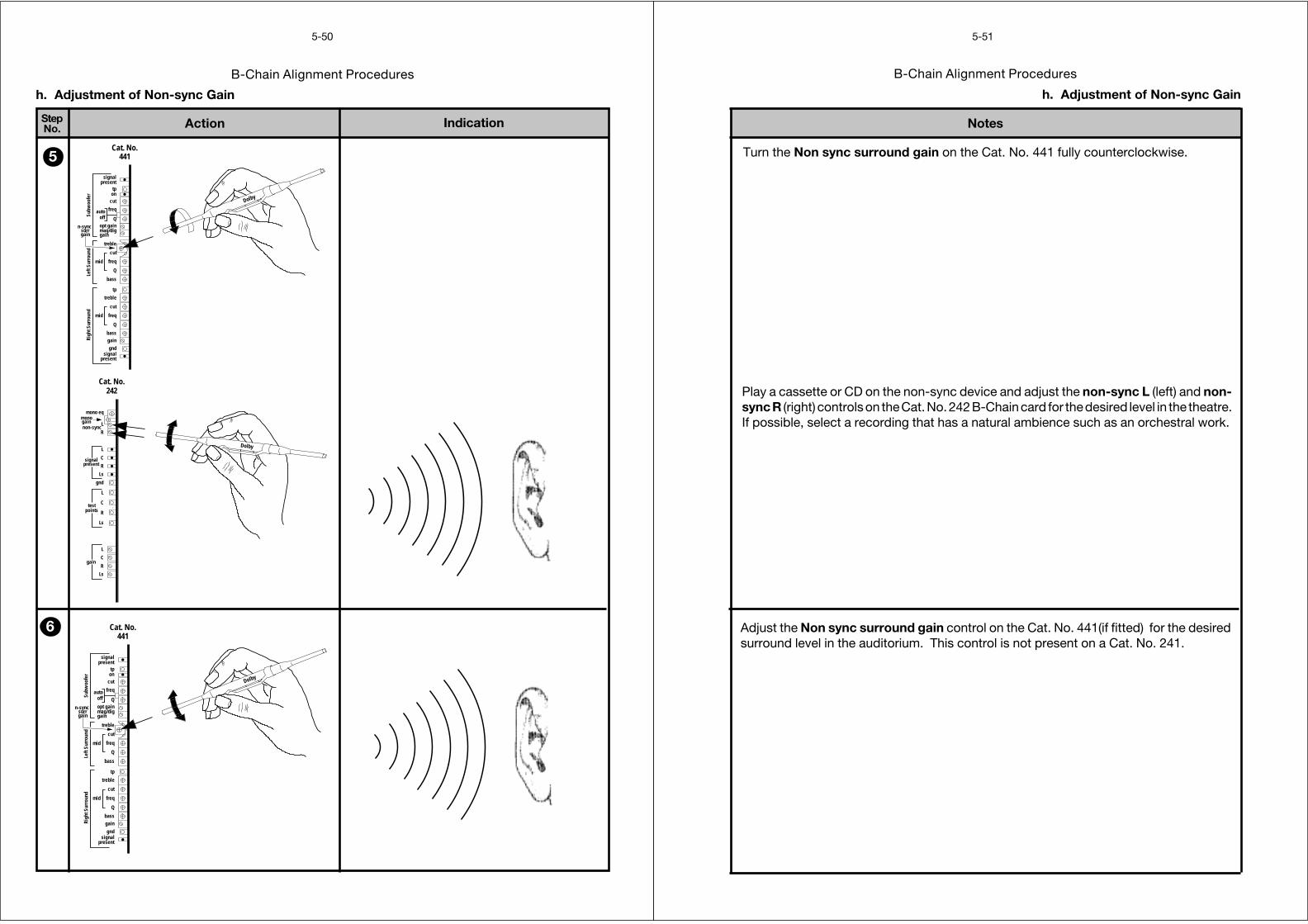
Action IndicationStepNo.
5-50
B-Chain Alignment Procedures
h. Adjustment of Non-sync Gain
5
6
Dolby
gainmono
non-sync
gain
pointstest
mono eq
Ls
R
C
L
Ls
R
C
L
gnd
Ls
R
C
L
R
L
signalpresent
Cat. No.242
Dolby
n-syncsurrgain
Q
on
presentsignal
gndgainbass
Q
mid freq
cut
treble
tp
bass
Q
freqmid
cut
treble
gainmag/digopt gain
offauto freq
cut
tppresent
signal
Subw
oofe
rLe
ft Su
rrou
ndRi
ght S
urro
und
Cat. No.441
Dolby
n-syncsurrgain
Q
on
presentsignal
gndgainbass
Q
mid freq
cut
treble
tp
bass
Q
freqmid
cut
treble
gainmag/digopt gain
offauto freq
cut
tppresent
signal
Subw
oofe
rLe
ft Su
rrou
ndRi
ght S
urro
und
Cat. No.441
B-Chain Alignment Procedures
Notes
5-51
h. Adjustment of Non-sync Gain
Turn the Non sync surround gain on the Cat. No. 441 fully counterclockwise.
Adjust the Non sync surround gain control on the Cat. No. 441(if fitted) for the desiredsurround level in the auditorium. This control is not present on a Cat. No. 241.
Play a cassette or CD on the non-sync device and adjust the non-sync L (left) and non-sync R (right) controls on the Cat. No. 242 B-Chain card for the desired level in the theatre.If possible, select a recording that has a natural ambience such as an orchestral work.
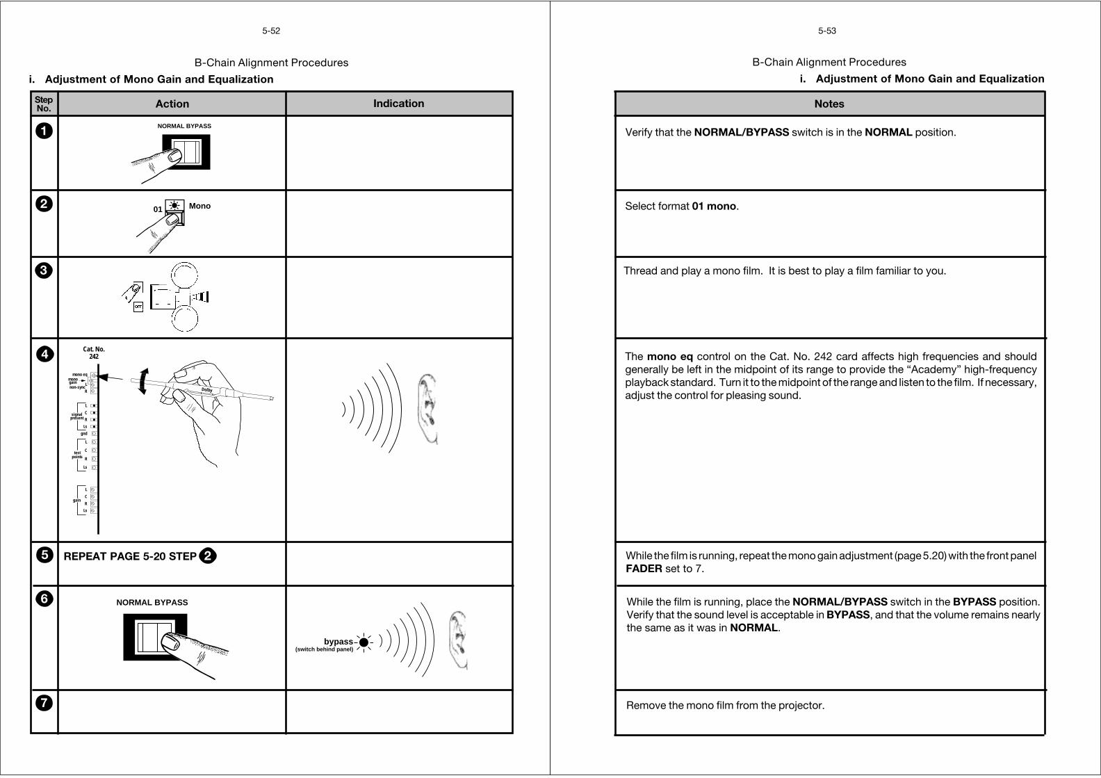
Action IndicationStepNo.
5-52
B-Chain Alignment Procedures
i. Adjustment of Mono Gain and Equalization
1 NORMAL BYPASS
2 01 Mono
3
4
Dolby
gainmono
non-sync
gain
pointstest
mono eq
Ls
R
C
L
Ls
R
C
L
gnd
Ls
R
C
L
R
L
signalpresent
Cat. No.242
5 REPEAT PAGE 5-20 STEP 2
bypass(switch behind panel)
NORMAL BYPASS6
7
B-Chain Alignment Procedures
Notes
5-53
i. Adjustment of Mono Gain and Equalization
Verify that the NORMAL/BYPASS switch is in the NORMAL position.
Select format 01 mono.
Thread and play a mono film. It is best to play a film familiar to you.
The mono eq control on the Cat. No. 242 card affects high frequencies and shouldgenerally be left in the midpoint of its range to provide the “Academy” high-frequencyplayback standard. Turn it to the midpoint of the range and listen to the film. If necessary,adjust the control for pleasing sound.
While the film is running, repeat the mono gain adjustment (page 5.20) with the front panelFADER set to 7.
While the film is running, place the NORMAL/BYPASS switch in the BYPASS position.Verify that the sound level is acceptable in BYPASS, and that the volume remains nearlythe same as it was in NORMAL.
Remove the mono film from the projector.
Action IndicationStepNo.
5-54
B-Chain Alignment Procedures
j. Final Checks
NORMAL BYPASS1
4NORMAL BYPASS
3
04 Dolby StereoA-type
2
JIFFYTEST FILM
CN 251–A subjective film for testing theatre sound
DOLBY STEREORunning time: 8 minutes.Picture format: 1.85:1 widescreen or 2.35:1 anamorphic.Sound format:
04stereo opticalwith surround
Dolby Laboratories, 100 Potrero Avenue,San Francisco, CA 94103-4813
Telephone 415-558-0200, Telex 34409, Facsimile 415-863-1373Dolby, the Double-D symbol and Dolby Stereo are trademarks
of Dolby Laboratories Licensing Corporation.S89/4784/8690
RECORDED IN
listen…CN 351–The Stereo Demonstration Film
DOLBY STEREORunning time: 8 minutes.Picture format: 2.35:1 anamorphic.Sound format:
04stereo opticalwith surround
Dolby Laboratories, 100 Potrero Avenue,San Francisco, CA 94103-4813
Telephone 415-558-0200, Telex 34409, Facsimile 415-863-1373Dolby, the Double-D symbol and Dolby Stereo are trademarks
of Dolby Laboratories Licensing Corporation.S89/4784/6776
RECORDED IN
B-Chain Alignment Procedures
Notes
5-55
j. Final Checks
Verify that the NORMAL/BYPASS switch is in the NORMAL position.
Remove the “Jiffy” film, return to NORMAL
Play the Dolby Cat. No. 351 “listen . . .” film on the newly aligned system. The filmconsists of a wide variety of short scenes — both live action and animated. Each scenewas selected to demonstrate different aspects of stereo sound. Evaluate the quality ofthe sound. If problems occur, contact the technical staff at Dolby Laboratories.
Thread and play the Dolby Cat. No. 251 “Jiffy” test film, if available, for a quick check ofthe system alignment. This film contains a series of tests, each of which is described bya male or female voice and is supplemented by captions on the screen to help identify thecauses of sound problems. Visual checks are also included to assist in identifying somepicture projection problems.
Press the format 04 Dolby Stereo A-type switch.

6-1
SECTION 6REFERENCE DIAGRAMS
Cat. No. 222 Dual Noise Reduction Module
CA
T. NO
. 240A O
PTIC
AL P
RE
-AM
PLIFIE
R C
AR
D
Slit LossEQ
Indicatorpower
P1 LED
P2 LED
25 Hz-18 kHz
25 Hz-18 kHz
Slit LossEQ
Slit LossEQ
Slit LossEQ
6
7Proj1 Left
-
+
2
1Proj2 Left
-
+
B
CProj1 Right
-
+
H
JProj2 Right
-
+
3 +
N
Gnd forProj 2
C/Ostatus
12
10
Ltoutput
Rtoutput
14
R
16
T
Auxoutputs
P1L
P2L
P1R
P2R
INPUTS
OUTPUTS
Cat. No. 241 Optical Bass Extension and Surround Equalizer Card
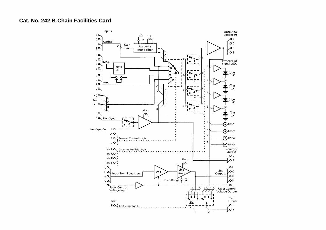
Cat. No. 242 B-Chain Facilities Card
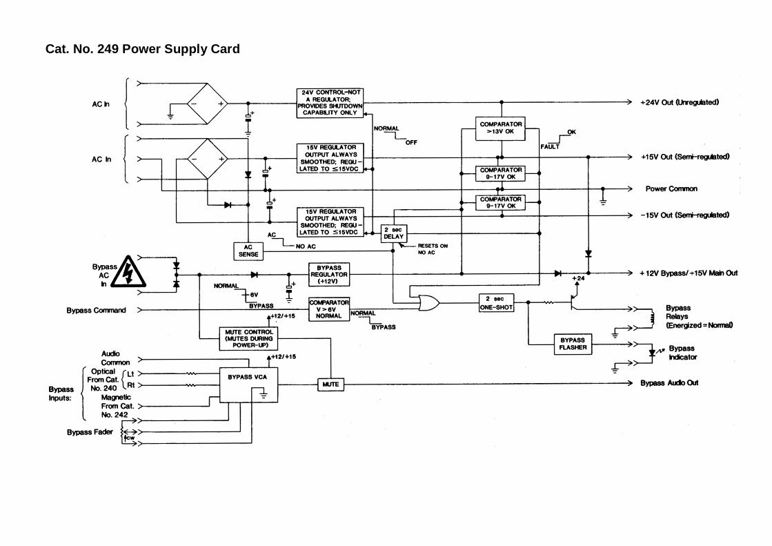
Cat. No. 249 Power Supply Card
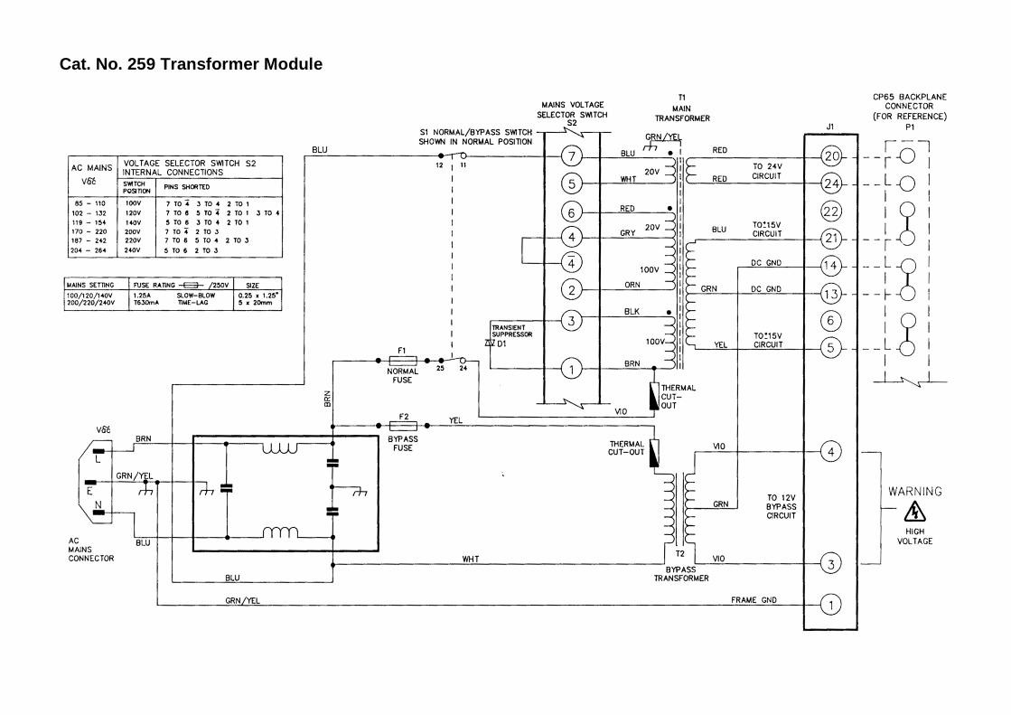
Cat. No. 259 Transformer Module
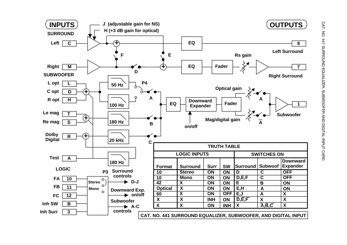
CA
T. NO
. 441 SU
RR
OU
ND
EQ
UA
LIZE
R, S
UB
WO
OFE
R A
ND
DIG
ITAL IN
PU
T CA
RD
C
T
S
R
10
11
12
B
3
+
+
+
+
+
A
180 Hz
180 Hz
100 Hz
50 Hz
20 kHz
M
L
D
H
EQ
EQ
Downward ExpanderEQ
Fader
Fader
8
1
7
SUBWOOFER
SURROUND
LOGIC
Left
Right
L opt
C opt
R opt
Le mag
Re mag
Dolby Digital
Test
FA
FB
FC
Inh SW
Inh Surr
OUTPUTS
Left Surround
Right Surround
Subwoofer
INPUTS
Surround controls
Subwoofer
controls
D-J
A-C
F
D
E
A
B
C
J (adjustable gain for NS)H (+3 dB gain for optical)
Optical gain
Mag/digital gain
A
A
Rs gain
CAT. NO. 441 SURROUND EQUALIZER, SUBWOOFER, AND DIGITAL INPUT
Downward Exp.on/off
on/off
Stereo
Mono
DownwardExpander
INH
Format Surround Surr SW Surround Subwoof10 Stereo ON ON D C10 Mono ON ON D,E,F C42 X ON ON E BOptical X ON ON E,H A60 X ON OFF E,J AX X INH ON D,E,F XX X ON X A,B,C
ONONXXX
TRUTH TABLE
LOGIC INPUTS SWITCHES ON
OFFOFF
P4
P3
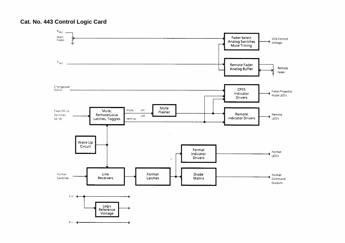
Cat. No. 443 Control Logic Card
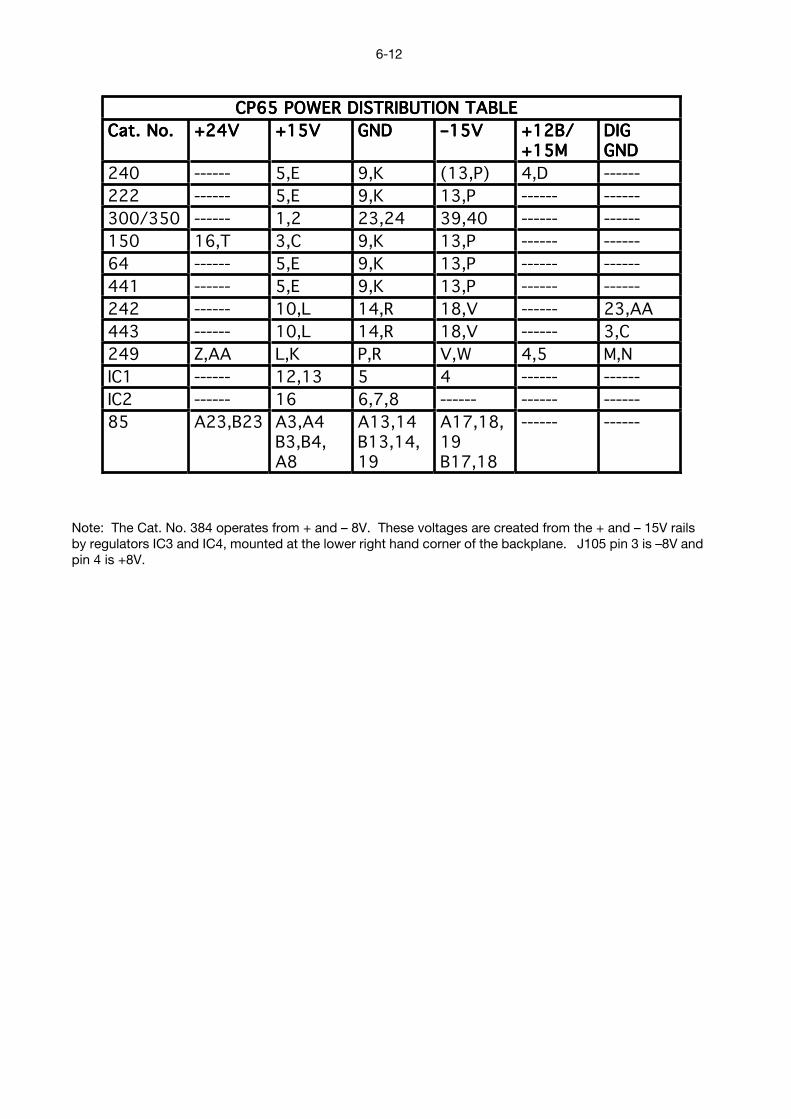
6-12
Note: The Cat. No. 384 operates from + and – 8V. These voltages are created from the + and – 15V railsby regulators IC3 and IC4, mounted at the lower right hand corner of the backplane. J105 pin 3 is –8V andpin 4 is +8V.
CCCCPPPP66665555 PPPPOOOOWWWWEEEERRRR DDDDIIIISSSSTTTTRRRRIIIIBBBBUUUUTTTTIIIIOOOONNNN TTTTAAAABBBBLLLLEEEE
CCCCaaaatttt.... NNNNoooo.... ++++22224444VVVV ++++11115555VVVV GGGGNNNNDDDD ––––11115555VVVV ++++11112222BBBB////++++11115555MMMM
DDDDIIIIGGGGGGGGNNNNDDDD
240 ------ 5,E 9,K (13,P) 4,D ------
222 ------ 5,E 9,K 13,P ------ ------
300/350 ------ 1,2 23,24 39,40 ------ ------
150 16,T 3,C 9,K 13,P ------ ------
64 ------ 5,E 9,K 13,P ------ ------
441 ------ 5,E 9,K 13,P ------ ------
242 ------ 10,L 14,R 18,V ------ 23,AA
443 ------ 10,L 14,R 18,V ------ 3,C
249 Z,AA L,K P,R V,W 4,5 M,N
IC1 ------ 12,13 5 4 ------ ------
IC2 ------ 16 6,7,8 ------ ------ ------
85 A23,B23 A3,A4B3,B4,A8
A13,14B13,14,19
A17,18,19B17,18
------ ------
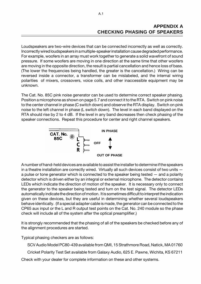
A.1
APPENDIX ACHECKING PHASING OF SPEAKERS
Loudspeakers are two-wire devices that can be connected incorrectly as well as correctly.Incorrectly wired loudspeakers in a multiple-speaker installation cause degraded performance.For example, woofers in an array must work together to generate a solid wavefront of soundpressure. If some woofers are moving in one direction at the same time that other woofersare moving in the opposite direction, the result is partial cancellation and hence loss of bass.(The lower the frequencies being handled, the greater is the cancellation.) Wiring can bereversed inside a connector, a transformer can be mislabeled, and the internal wiringpolarities of mixers, crossovers, voice coils, and other inaccessible equipment may beunknown.
The Cat. No. 85C pink noise generator can be used to determine correct speaker phasing.Position a microphone as shown on page 5.7 and connect it to the RTA. Switch on pink noiseto the center channel in phase (C switch down) and observe the RTA display. Switch on pinknoise to the left channel in phase (L switch down). The level in each band displayed on theRTA should rise by 2 to 4 dB. If the level in any band decreases then check phasing of thespeaker connections. Repeat this procedure for center and right channel speakers.
A number of hand-held devices are available to assist the installer to determine if the speakersin a theatre installation are correctly wired. Virtually all such devices consist of two units —a pulse or tone generator which is connected to the speaker being tested — and a polaritydetector which is driven either by an integral or external microphone. The detector containsLEDs which indicate the direction of motion of the speaker. It is necessary only to connectthe generator to the speaker being tested and turn on the test signal. The detector LEDsautomatically indicate the direction of motion. It is sometimes difficult to interpret the indicationgiven on these devices, but they are useful in determining whether several loudspeakersbehave identically. (If a special adapter cable is made, the generator can be connected to theCP65 aux input or the L and R output test points on the Cat. No. 240 module so the phasecheck will include all of the system after the optical preamplifier.)
It is strongly recommended that the phasing of all of the speakers be checked before any ofthe alignment procedures are started.
Typical phasing checkers are as follows:
SCV Audio Model PC80-439 available from QMI, 15 Strathmore Road, Natick, MA 01760
Cricket Polarity Test Set available from Galaxy Audio, 625 E. Pawne, Wichita, KS 67211
Check with your dealer for complete information on these and other systems.
IN PHASE
OFF
OUT OF PHASE
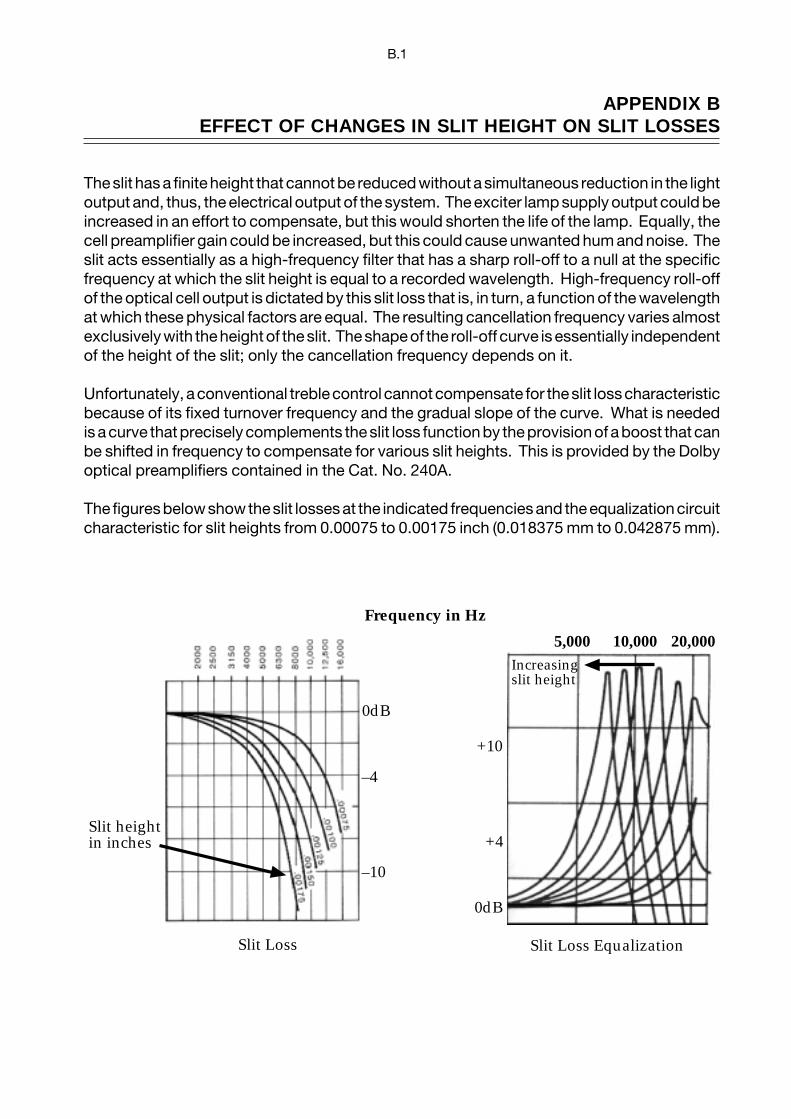
B.1
APPENDIX BEFFECT OF CHANGES IN SLIT HEIGHT ON SLIT LOSSES
The slit has a finite height that cannot be reduced without a simultaneous reduction in the lightoutput and, thus, the electrical output of the system. The exciter lamp supply output could beincreased in an effort to compensate, but this would shorten the life of the lamp. Equally, thecell preamplifier gain could be increased, but this could cause unwanted hum and noise. Theslit acts essentially as a high-frequency filter that has a sharp roll-off to a null at the specificfrequency at which the slit height is equal to a recorded wavelength. High-frequency roll-offof the optical cell output is dictated by this slit loss that is, in turn, a function of the wavelengthat which these physical factors are equal. The resulting cancellation frequency varies almostexclusively with the height of the slit. The shape of the roll-off curve is essentially independentof the height of the slit; only the cancellation frequency depends on it.
Unfortunately, a conventional treble control cannot compensate for the slit loss characteristicbecause of its fixed turnover frequency and the gradual slope of the curve. What is neededis a curve that precisely complements the slit loss function by the provision of a boost that canbe shifted in frequency to compensate for various slit heights. This is provided by the Dolbyoptical preamplifiers contained in the Cat. No. 240A.
The figures below show the slit losses at the indicated frequencies and the equalization circuitcharacteristic for slit heights from 0.00075 to 0.00175 inch (0.018375 mm to 0.042875 mm).
Frequency in Hz
5,000 10,000 20,000Increasingslit height
0dB
–4
–10
+10
0dB
+4Slit heightin inches
Slit Loss Slit Loss Equalization
C-1
APPENDIX CCP65M (MONO) INSTRUCTIONS
1. Operation
The CP65 can be configured for mono-only operation. Systems so equipped are shipped withonly the center channel Cat. No. 64 house equalization module and without the Cat. No. 150surround decoder module and Cat. No. 241 or 441 surround equalizer and optical bassextension board. A Cat. No. 327A mono board replaces the Cat. No. 150 module. The Cat.No. 443 control board should have diode D56 in the INC (Inhibit Center) row removed.
When the system is so configured, optical and non-sync sources will be summed and sent tothe center channel via the fader or faders and house equalization. When using non-syncinputs the left, right, and center LEDs on the Cat. No. 242 will light although signal will onlybe present at the center channel output. Magnetic and auxiliary center channel inputs can beselected by choosing the appropriate format using the front panel controls.
Mono films should be played using format 01 Mono. However, with the CP65M, Dolby Stereofilms can be screened with the noise reduction and wider frequency response usually onlyavailable in Dolby Stereo theatres. Simply select format 04 Dolby Stereo A-type. This turnson the noise reduction circuitry and disables the mono filter. Although the sound will bemonophonic, the quality of reproduction will be improved. If your CP65M is fitted with Cat.No. 300 or 350 modules, you can play Dolby Stereo SR prints best by selecting format 05Dolby Stereo SR.
Follow the level adjustment procedures in the installation and alignment manual. Adjust onlythe center channel.
2. Cat. No. 327A Circuit Description
The Cat. No. 327A mono board accepts four inputs: optical Lt and Rt from the Cat. No. 222or Cat. Nos. 350/300 at both 300 and 500 mV levels. All inputs are combined and fed to theoutput, which appears at the same pin as the center output of a Cat. No. 150.
The Cat. No. 327A may be replaced by a Cat. No. 327 but this will require re-adjustment oflevels. Follow the level adjustment procedures in the installation and alignment manual.Adjust only the center channel.
A signal present LED is provided at the output of the Cat. No. 327A. It will come on at about15 dB below Dolby level, which is the same threshold as the other signal present lights in thesystem.
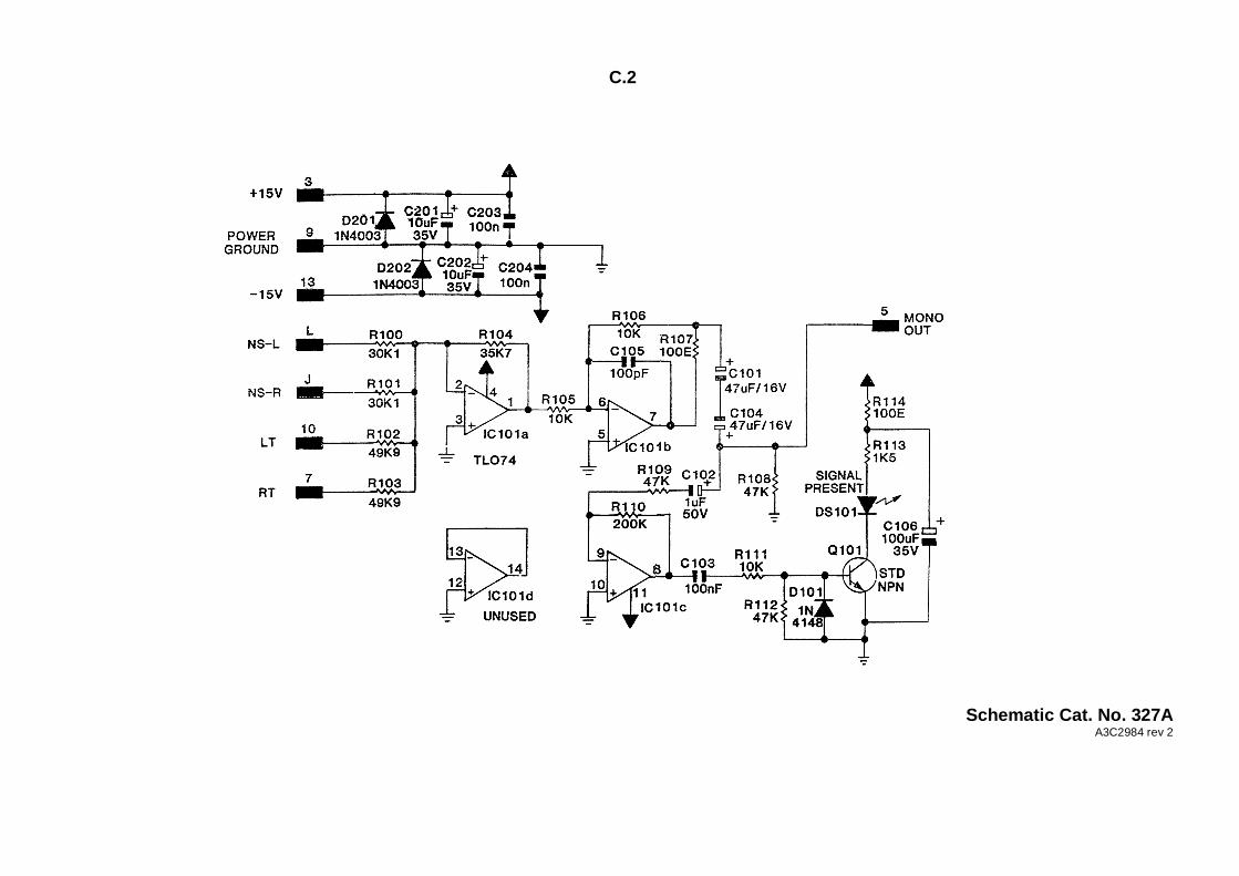
C.2
Schematic Cat. No. 327AA3C2984 rev 2
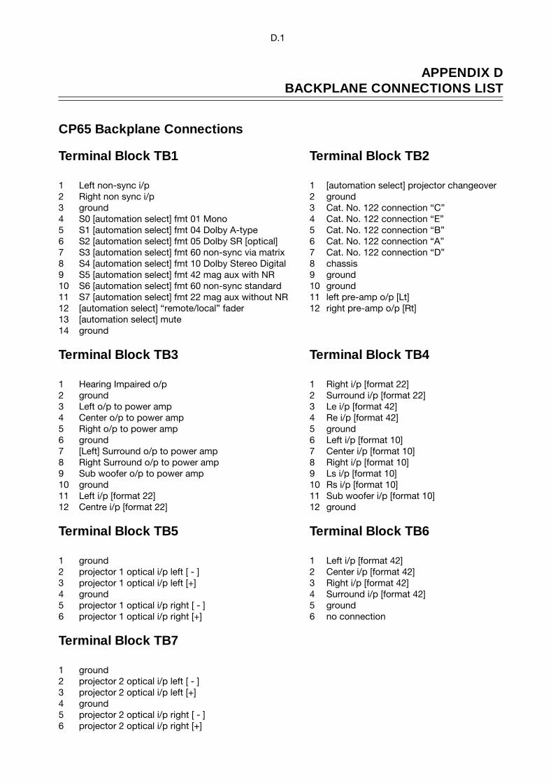
D.1
APPENDIX DBACKPLANE CONNECTIONS LIST
CP65 Backplane Connections
Terminal Block TB1 Terminal Block TB2
1 Left non-sync i/p 1 [automation select] projector changeover2 Right non sync i/p 2 ground3 ground 3 Cat. No. 122 connection “C”4 S0 [automation select] fmt 01 Mono 4 Cat. No. 122 connection “E”5 S1 [automation select] fmt 04 Dolby A-type 5 Cat. No. 122 connection “B”6 S2 [automation select] fmt 05 Dolby SR [optical] 6 Cat. No. 122 connection “A”7 S3 [automation select] fmt 60 non-sync via matrix 7 Cat. No. 122 connection “D”8 S4 [automation select] fmt 10 Dolby Stereo Digital 8 chassis9 S5 [automation select] fmt 42 mag aux with NR 9 ground10 S6 [automation select] fmt 60 non-sync standard 10 ground11 S7 [automation select] fmt 22 mag aux without NR 11 left pre-amp o/p [Lt]12 [automation select] “remote/local” fader 12 right pre-amp o/p [Rt]13 [automation select] mute14 ground
Terminal Block TB3 Terminal Block TB4
1 Hearing Impaired o/p 1 Right i/p [format 22]2 ground 2 Surround i/p [format 22]3 Left o/p to power amp 3 Le i/p [format 42]4 Center o/p to power amp 4 Re i/p [format 42]5 Right o/p to power amp 5 ground6 ground 6 Left i/p [format 10]7 [Left] Surround o/p to power amp 7 Center i/p [format 10]8 Right Surround o/p to power amp 8 Right i/p [format 10]9 Sub woofer o/p to power amp 9 Ls i/p [format 10]10 ground 10 Rs i/p [format 10]11 Left i/p [format 22] 11 Sub woofer i/p [format 10]12 Centre i/p [format 22] 12 ground
Terminal Block TB5 Terminal Block TB6
1 ground 1 Left i/p [format 42]2 projector 1 optical i/p left [ - ] 2 Center i/p [format 42]3 projector 1 optical i/p left [+] 3 Right i/p [format 42]4 ground 4 Surround i/p [format 42]5 projector 1 optical i/p right [ - ] 5 ground6 projector 1 optical i/p right [+] 6 no connection
Terminal Block TB7
1 ground2 projector 2 optical i/p left [ - ]3 projector 2 optical i/p left [+]4 ground5 projector 2 optical i/p right [ - ]6 projector 2 optical i/p right [+]
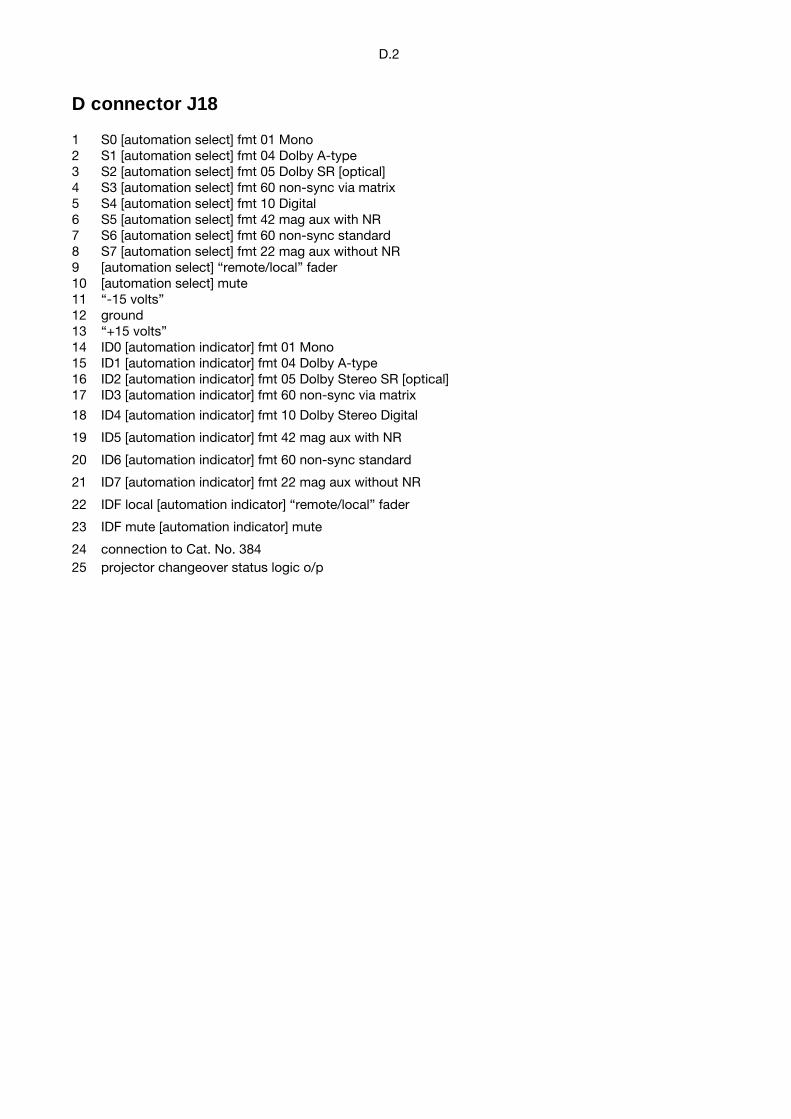
D.2
D connector J18
1 S0 [automation select] fmt 01 Mono2 S1 [automation select] fmt 04 Dolby A-type3 S2 [automation select] fmt 05 Dolby SR [optical]4 S3 [automation select] fmt 60 non-sync via matrix5 S4 [automation select] fmt 10 Digital6 S5 [automation select] fmt 42 mag aux with NR7 S6 [automation select] fmt 60 non-sync standard8 S7 [automation select] fmt 22 mag aux without NR9 [automation select] “remote/local” fader10 [automation select] mute11 “-15 volts”12 ground13 “+15 volts”14 ID0 [automation indicator] fmt 01 Mono15 ID1 [automation indicator] fmt 04 Dolby A-type16 ID2 [automation indicator] fmt 05 Dolby Stereo SR [optical]17 ID3 [automation indicator] fmt 60 non-sync via matrix
18 ID4 [automation indicator] fmt 10 Dolby Stereo Digital
19 ID5 [automation indicator] fmt 42 mag aux with NR
20 ID6 [automation indicator] fmt 60 non-sync standard
21 ID7 [automation indicator] fmt 22 mag aux without NR
22 IDF local [automation indicator] “remote/local” fader
23 IDF mute [automation indicator] mute
24 connection to Cat. No. 38425 projector changeover status logic o/p