Embed Size (px)
Citation preview

Model CIM-1200K Dual Format ANI Encoder
for Kenwood Radios
GE Star® AND MDC-1200® Identification Encoder with Kenwood mating connector
Instruction Manual Rev 100505
(Photo enlarged to show detail)
© 2010 Cimarron Technologies Corp., Escondido, CA, USA. All rights reserved. No part of this manual may be reproduced in any way without the express written permission of Cimarron Technologies Corporation.

MODEL CIM-1200K ANI ENCODER © 2010 Cimarron Technologies Corporation All rights reserved Cimarron Technologies Inc. 934 S. Andreasen Suite G Escondido, CA 92029 USA Voice: 760-738-3282 (sales) 760-738-3285 (Service) FAX: 760-480-0233 Email: [email protected] Web: www.cimtechcorp.com
Cimarron Technologies Corporation is a licensee of the Motorola MDC-1200 Protocol technology. MDC-1200® is a registered trademark of Motorola Inc. GE Star® is a registered trademark of General Electric Corporation Manual revision CIM-1200K 100505

T a b l e o f C o n t e n t s
C H A P T E R 1 Features and Capabilities _________________________ 6
What Is the CIM-1200K _____________________________________________________ 6
Capabilities ________________________________________________________________ 6
Specifications ______________________________________________________________ 8
C H A P T E R 2 Installation _____________________________________ 9
Installation in the x180 Series Radio ___________________________________________ 9 Configuring the Kenwood Radio _____________________________________________________ 9
Installation in the TK-2170/3170 Radios _______________________________________ 10 Configuring the Kenwood Radio ____________________________________________________ 11
Installation in the TK-5210 Radio ____________________________________________ 11
Installation in the TK-5710 Radio ____________________________________________ 11
Jumper Information _______________________________________________________ 11
Jumper Definitions _________________________________________________________ 12
Data Deviation Adjustment __________________________________________________ 13
Pad Information ___________________________________________________________ 13
C H A P T E R 3 Programming __________________________________ 15
QuikWare Programming Software ___________________________________________ 15
Opening Page _____________________________________________________________ 16
Common Settings __________________________________________________________ 19 Attack Delay ___________________________________________________________________ 19 Acknowledgment Delay ___________________________________________________________ 19 Startup Delay ___________________________________________________________________ 19 ANI Repeat Timer _______________________________________________________________ 20 TX Time Out Timer ______________________________________________________________ 20 TX Data Level __________________________________________________________________ 20 PTT Sidetone ___________________________________________________________________ 20 Mute Data _____________________________________________________________________ 20 Mute on Incorrect Key ____________________________________________________________ 20 MDC Call Alert Encode ___________________________________________________________ 20 MDC Wildcard Enable ___________________________________________________________ 20 Unlock PIN ____________________________________________________________________ 20 Key Follows PTT ________________________________________________________________ 20 Respond to Channel Codes ________________________________________________________ 21 Enable Keypad __________________________________________________________________ 21 Display Received ANI ____________________________________________________________ 21 Canned Message Type ____________________________________________________________ 21 Inversion Preamble ______________________________________________________________ 21 Disconnect Delay ________________________________________________________________ 21 Pre Mute _______________________________________________________________________ 21
Emergency Settings ________________________________________________________ 21 Open Microphone Monitor on Emergency TX time _____________________________________ 21 Open Microphone Monitor on Emergency RX time _____________________________________ 22 Repeat Max ____________________________________________________________________ 22 Repeat Period ___________________________________________________________________ 22

Emergency TX Warning Tone ______________________________________________________ 22
ManDown Settings _________________________________________________________ 22 Open Microphone Monitor on Man Down TX time _____________________________________ 23 Open Microphone Monitor on Man Down RX time _____________________________________ 23 Repeat Max ____________________________________________________________________ 23 Repeat Period ___________________________________________________________________ 23 Man Down TX Warning Tone ______________________________________________________ 24 Man Down Warning Delay ________________________________________________________ 24 Man Down Activation Delay _______________________________________________________ 24
Audio Settings _____________________________________________________________ 24
Digital I/O Control _________________________________________________________ 26
TX Mode _________________________________________________________________ 27 Conventional ___________________________________________________________________ 27 Trunked _______________________________________________________________________ 27 Trunk Debounce_________________________________________________________________ 28 Trunk Key Time _________________________________________________________________ 28 Trunk Time Out _________________________________________________________________ 28
Channel Settings ___________________________________________________________ 28 Inv Type _______________________________________________________________________ 30 Fix Frq ________________________________________________________________________ 30 Min Frq _______________________________________________________________________ 30 Max Frq _______________________________________________________________________ 30 Min Dwl _______________________________________________________________________ 30 Max Dwl ______________________________________________________________________ 30 P/U INV _______________________________________________________________________ 30 ANI Type ______________________________________________________________________ 30 ANI Loc _______________________________________________________________________ 30 PTT ID – EM ID – M/D ID ________________________________________________________ 30 PTT MSG ______________________________________________________________________ 30 TOT MSG _____________________________________________________________________ 31 EM MSG ______________________________________________________________________ 31 M/D MSG _____________________________________________________________________ 31 Group ID ______________________________________________________________________ 31 Mute Mode _____________________________________________________________________ 31 Crit ANI _______________________________________________________________________ 31 CRIT RVRT ____________________________________________________________________ 31 C T ___________________________________________________________________________ 31 ACK __________________________________________________________________________ 31 Base ID _______________________________________________________________________ 31 Encryption Key _________________________________________________________________ 31
The MenuBar _____________________________________________________________ 32 Communications ________________________________________________________________ 32 Channels_______________________________________________________________________ 33 Device ________________________________________________________________________ 33
C H A P T E R 4 Operation _____________________________________ 34
ANI-ID___________________________________________________________________ 34
Time-out-timer ____________________________________________________________ 34
Emergency _______________________________________________________________ 34
Man-Down _______________________________________________________________ 34
Status ____________________________________________________________________ 35
Canned Messages __________________________________________________________ 35
Multiple ANI format and ID Capability _______________________________________ 35
C H A P T E R 5 Technical Information ___________________________ 37
GE Star® Format Selections _________________________________________________ 37
Format Definitions _________________________________________________________ 37
GE Star® Message Descriptions ______________________________________________ 37
MDC-1200® Message Type __________________________________________________ 38
Code Line Interpretation ____________________________________________________ 38
Trunking Operation ________________________________________________________ 40 Systems where Trunk Key Time and Trunk Timeout are set to the same value (LTR): __________ 40
Emergency __________________________________________________________________ 40 PTT ANI beginning send not “Key follows PTT” ____________________________________ 40 PTT ANI end send not “Key follows PTT” _________________________________________ 41 PTT ANI beginning send with “Key follows PTT” ___________________________________ 41 PTT ANI end send with “Key follows PTT” ________________________________________ 41
Systems where Trunk Key Time and Trunk Timeout are not set to the same value (MPT and others):
______________________________________________________________________________ 41 Emergency __________________________________________________________________ 41 PTT ANI beginning send not “Key follows PTT” ____________________________________ 42 PTT ANI end send not “Key follows PTT” _________________________________________ 42 PTT ANI beginning send with “Key follows PTT” ___________________________________ 43 PTT ANI end send with “Key follows PTT” ________________________________________ 43
Component Location _______________________________________________________ 43
Schematic ________________________________________________________________ 44
C H A P T E R 6 Troubleshooting ________________________________ 45
Installation Hints __________________________________________________________ 45
Isolating System Problems __________________________________________________ 45
Equipment Problems _______________________________________________________ 45
C H A P T E R 7 Product Support ________________________________ 47
A P P E N D I X A Quick Start Guide for QuikWare Software ________ 48

Chapter 1 Features and Capabilities 6
C H A P T E R 1 Features and Capabilities
What Is the CIM-1200K The Cimarron Technologies' Model CIM-1200K, ANI/Emergency ID Encoder is a dual format encoder. It can be programmed to operate in GE Star® or MDC-1200® modes. The unit provides Automatic Numeric Identification (ANI) of the associated radio transmitter each time the microphone push-to-talk (PTT) switch is activated and is capable of transmitting other data messages as well. Typically the unit is programmed to encode “Stuck-Microphone”, “Emergency”, and “Man-Down” messages but can be preprogrammed for any valid special message. The Model CIM-1200K can also be used as a monitoring or alarm transmission module by programming status and “canned” messages and interpreting them as sensor inputs at the decoding site. The CIM-1200K is available with either the 26 pin or the 20 pin mating connector. Order either CIM-1200K-26 or CIM-1200K-20 as required.
Capabilities Identify every transmission
Reduce nuisance and obscene transmissions
Emergency and Man-Down situations instantly identified
Microphone monitoring mode during emergency/man down cycles
Trunking compatible
Stuck microphone identification
Time-Out-Timer with alert tone
ANI identification at beginning, End or Both
Audible Man-Down and Emergency alert
Multiple ID/personality capability
Dual format capability
Flexible message coding allows special signaling capabilities
Programmable using Cimarron QuikWare software and a USB programming cable
Able to be used as a status encoder for both MDC-1200® and GE Star®
Very low current consumption
Extended ID range MDC-1200® ID’s to DEEE and GE Star® to 16,383
Software controlled output adjustment – no more potentiometer to fail.
Sine wave output provides cleaner system functioning and compliance
Programmable audible alerts allow for individually adjusting of tone frequency and amplitude

Chapter 1 Features and Capabilities 7
In order to realize these capabilities the CIM-1200K must be correctly installed and programmed. Some features may require additional equipment not supplied. The CIM-1200K is programmed with “defaults” which allow compatibility with most installations when received from the factory. The device is programmed via the Cimarron Technologies QuikWare programming software and a USB cable which has three grabbers to attach to the labeled programming holes on the CIM-1200K.
Chapter 1 Features and Capabilities 8
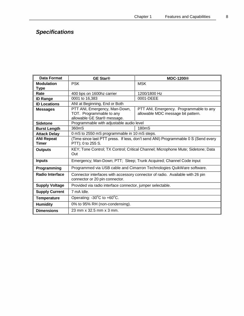
Specifications
Data Format GE Star® MDC-1200®
Modulation Type
PSK MSK
Rate 400 bps on 1600hz carrier 1200/1800 Hz
ID Range 0001 to 16,383 0001-DEEE
ID Locations ANI at Beginning, End or Both
Messages PTT ANI, Emergency, Man-Down, TOT. Programmable to any allowable GE Star® message.
PTT ANI, Emergency. Programmable to any allowable MDC message bit pattern.
Sidetone Programmable with adjustable audio level
Burst Length 360mS 180mS
Attack Delay 0 mS to 2550 mS programmable in 10 mS steps.
ANI Repeat Timer
(Time since last PTT press. If less, don’t send ANI) Programmable 0 S (Send every PTT); 0 to 255 S.
Outputs KEY; Tone Control; TX Control; Critical Channel; Microphone Mute; Sidetone; Data Out
Inputs Emergency; Man-Down; PTT; Sleep; Trunk Acquired; Channel Code input
Programming Programmed via USB cable and Cimarron Technologies QuikWare software.
Radio Interface Connector interfaces with accessory connector of radio. Available with 26 pin connector or 20 pin connector.
Supply Voltage Provided via radio interface connector, jumper selectable.
Supply Current 7 mA Idle.
Temperature Operating: -30oC to +60
oC.
Humidity 0% to 95% RH (non-condensing).
Dimensions 23 mm x 32.5 mm x 3 mm.

Chapter 2 Installation 9
C H A P T E R 2 Installation
Installation in the x180 Series Radio The x180 series radio uses the CIM-1200K-26 to interface with the 26 pin connector of the radio. Install jumpers 2, 4, F, V, and H on the CIM-1200K board. Remove any other jumpers. Locate the accessory connector as shown in the below pictures.
TK-2180/TK-3180 TK-7180/TK-8180
Configuring the Kenwood Radio
Using the Kenwood KPG-89D software, select “Program” > “Read Data from the Transceiver”. The Read Data window appears. Click “Read”. When reading is completed, select “Edit” > “Extended Function”. The Extended Function window appears:
TK-2180/TK-3180 TK-7180/TK-8180 Select “ANI Board” from the external device pull-down menu. Then select LOK (Continuous) for the OPT1 pull-down menu.
Chapter 2 Installation 10
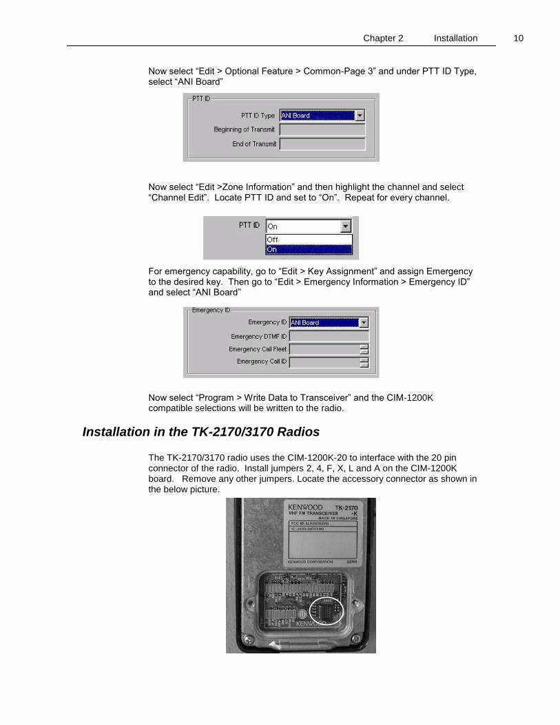
Now select “Edit > Optional Feature > Common-Page 3” and under PTT ID Type, select “ANI Board” Now select “Edit >Zone Information” and then highlight the channel and select “Channel Edit”. Locate PTT ID and set to “On”. Repeat for every channel. For emergency capability, go to “Edit > Key Assignment” and assign Emergency to the desired key. Then go to “Edit > Emergency Information > Emergency ID” and select “ANI Board” Now select “Program > Write Data to Transceiver” and the CIM-1200K compatible selections will be written to the radio.
Installation in the TK-2170/3170 Radios The TK-2170/3170 radio uses the CIM-1200K-20 to interface with the 20 pin connector of the radio. Install jumpers 2, 4, F, X, L and A on the CIM-1200K board. Remove any other jumpers. Locate the accessory connector as shown in the below picture.

Chapter 2 Installation 11
Configuring the Kenwood Radio
Using the Kenwood KPG-101D software, select “Program” > “Read Data from the Transceiver”. The Read Data window appears. Click “Read”. When reading is completed, select “Product Information” from the “Model” pull-down window. The Product Information window appears: Select “ANI Board” from the “Optional Board” dropdown list. Then, on the Zone Information window, select each channel which ANI is desired, then select channel edit and turn on “PTT ID”. If emergency functions are desired, select “Emergency Information” from the Edit pull-down menu. In the Emergency Information window, locate the Emergency ID section and select “Option board” from the Emergency ID pull-down list. Assign a button to the emergency function. Write the new information to the radio.
Installation in the TK-5210 Radio For the TK-5210 radio, use the CIM-1200K-26 and install jumpers 2, 4, E and H. Remove any other jumpers. Using the Kenwood KPG-95D software software, select “Extended Function”. Set “Optional Board” to ANI BOARD; Select “Key Assignment”. Set “Orange Key” to EMERGENCY; Select “Personal”, select “System”, select “Personality” and set PTT ID to “ON” for desired personalities.
Installation in the TK-5710 Radio For the TK-5710 radio, install jumpers 2, 4, E and H. Remove any other jumpers. Using the Kenwood KPG-95D software, select “Extended Function”. Set “Optional Board” to ANI BOARD and set OPT1 to “TOR”; select, “Personal”, select “Personal Features”, “Emergency”, “Emergency ID” and set to “ANI Board”. Select “Key Assignment” and Set the desired button to EMERGENCY; Select “Personal”, select “Personality”, “Analog” and set PTT ID to “ON” for desired personalities.
Jumper Information The CIM-1200K is supplied with jumpers 2, 4, F, H and V installed. To remove a jumper, use the fine tip soldering iron and solder wick to wipe the jumper off. To install other jumpers, use a fine tip soldering iron and create a solder bridge.
Chapter 2 Installation 12
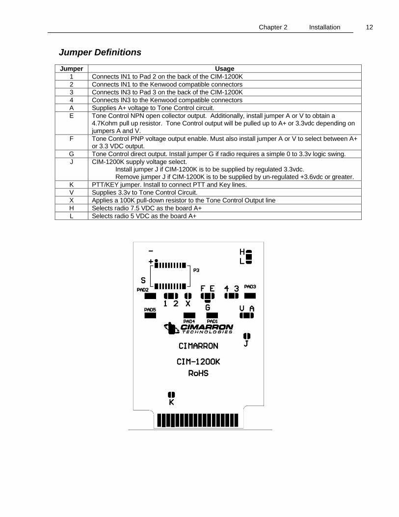
Jumper Definitions
Jumper Usage
1 Connects IN1 to Pad 2 on the back of the CIM-1200K
2 Connects IN1 to the Kenwood compatible connectors
3 Connects IN3 to Pad 3 on the back of the CIM-1200K
4 Connects IN3 to the Kenwood compatible connectors
A Supplies A+ voltage to Tone Control circuit.
E Tone Control NPN open collector output. Additionally, install jumper A or V to obtain a 4.7Kohm pull up resistor. Tone Control output will be pulled up to A+ or 3.3vdc depending on jumpers A and V.
F Tone Control PNP voltage output enable. Must also install jumper A or V to select between A+ or 3.3 VDC output.
G Tone Control direct output. Install jumper G if radio requires a simple 0 to 3.3v logic swing.
J CIM-1200K supply voltage select. Install jumper J if CIM-1200K is to be supplied by regulated 3.3vdc. Remove jumper J if CIM-1200K is to be supplied by un-regulated +3.6vdc or greater.
K PTT/KEY jumper. Install to connect PTT and Key lines.
V Supplies 3.3v to Tone Control Circuit.
X Applies a 100K pull-down resistor to the Tone Control Output line
H Selects radio 7.5 VDC as the board A+
L Selects radio 5 VDC as the board A+

Chapter 2 Installation 13
Data Deviation Adjustment The CIM-1200K data deviation is adjusted by software selection. The value can be programmed between 1 and 255. Settings between 1 and 128 will result in output levels from 0 vpp to 250 mvpp. Settings between 128 and 255 result in output levels from 250 mvpp to the maximum output of 2 VPP. Modify the value of Output Level until data deviation is just below voice deviation. It is most appropriate to start at a deviation that is much lower than voice and then adjust up until the correct point is reached.
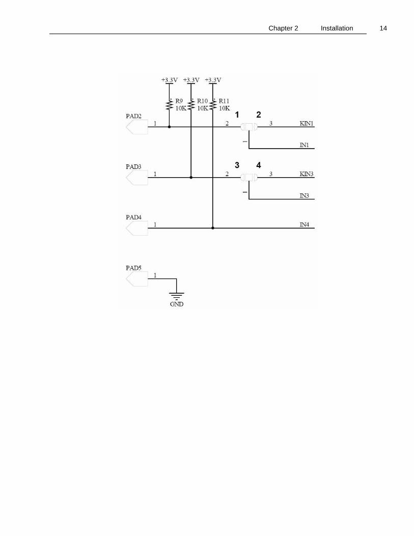
Pad Information There are five solder pads on the back of the CIM-1200K to accommodate unique applications. The schematic below shows the connection of OUT3 to PAD1 which is a solder pad on the back of the CIM-1200K board. OUT3 does not connect to the Kenwood interface connectors so it is totally isolated from radio circuitry. This output can be programmed and used for unique or enhanced installations. Note the schematic of inputs 1, 3 and 4. Jumpers 2 and 4 are the default connections and are inserted at the factory. These jumpers connect inputs IN1 and IN3 to the Kenwood interface connector. Replacing these jumpers with jumpers 1 and 3 would isolate IN1 and IN3 from the radio circuitry and connect them to pull-up resistors and solder pads on the back of the CIM-1200K for unique applications. IN4 is dedicated to solder PAD4 and can be programmed and used as required. PAD5 is a convenient ground point if using an external Man Down tilt sensor.
Chapter 2 Installation 14

Chapter 3 Programming 15
C H A P T E R 3 Programming
Many functions and features of the CIM-1200K are user programmable. In addition to signaling type, ID and radio interface parameters, the device can be optimized for the application’s particular needs.
QuikWare Programming Software Cimarron Technologies QuikWare programming software is used to program the latest Cimarron devices that include both the “CIM” series of ANI devices as well as the “QS” and “VQS” combination secure voice and ANI devices. A license is required to activate the software. The license necessary for the “CIM” series is distributed at no charge and permits the programming of only the “CIM” ANI boards. The program is distributed either on a CD or can be downloaded from our website www.cimtechcorp.com. Click the Icon and follow the installation directions. The routine will check your computer system and install any required components. When the installation is complete, you will need to import the license. Start QuikWare and on the menu bar, select File and then click on “Import License”. You will be asked for the location of the .cimlicense file. This will be either on your CD, or if you downloaded the QuikWare, Cimarron will email you the generic license that is required to activate QuikWare for programming the “CIM” family of ANI devices.

Chapter 3 Programming 16
The CIM-1200K is programmed using the associated USB programming cable. Remove the board from the host radio and connect it to the programming cable as shown. The Cimarron QuikWare software is used for selection of desired parameters.
Opening Page Upon starting, the QuikWare software program will open with the page shown on the next page. This is the Common Settings window of the Global Settings tab. In addition to the Common Settings, you can also access settings for Emergency, Man Down, Audio, Digital I/O and TX Mode. The Menu Bar provides access to the following windows: File, Edit, Communications, Channels, Device and Help.

Chapter 3 Programming 17

Chapter 3 Programming 18
To start using the software, from the menu bar, select “Device” and choose the CIM-1200 from the list. Then from the menu bar, select “Communications” and “Setup” and select the correct computer COM port that your programming cable is connected. If you are not sure which port the computer has assigned to your USB programming cable, press “Start”, right click on “My Computer”, select Properties – Hardware – Device Manager - then, scroll down to “Ports –(COM & LPT)”. When you open “Ports (COM & LPT) you will be presented with a list of existing COM ports. Look for the one that defines your USB Serial Device. In parentheses it will describe which COM port has been assigned to your USB programming cable.

Chapter 3 Programming 19
Common Settings
Attack Delay
0ms to 2550ms in steps of 10ms. [Default 500mS] The period of time from when the user keys the radio and the data begins to be transmitted. This delay allows the communications system to stabilize and be ready for transmission.
Acknowledgment Delay
Not available in the CIM-1200K
Startup Delay
(0mS to 2550 mS in 10 mS steps)[Default 500mS] This parameter holds off the startup of the device after power is applied. Used to ensure host radio stability on power up.

Chapter 3 Programming 20
ANI Repeat Timer
(time since last PTT press. If less, don’t send PTT ANI) (0=send every PTT; 10s, 20s, 40s, 60s, 90s, 120s) [Default 0] Used to reduce the amount of data transmissions. If the selected time since the last PTT press is not exceeded, data is not transmitted with that PTT press.
TX Time Out Timer
(OFF,30s, 60s, 90s, 120s) [Default: OFF] If the radio is held keyed up for greater than the selected time, the ID is transmitted and the radio is automatically unkeyed.
TX Data Level
(0 – 255) [Default 200] The CIM-1200K data deviation is adjusted by software selection. The value can be programmed between 1 and 255. Settings between 1 and 128 will result in output levels from 0 VPP to 250 mVPP (open output). Settings between 128 and 255 result in output levels from 250 mVPP to the maximum output of 2 VPP (open output). Adjust the setting until data deviation is just below voice deviation. It is most appropriate to start at a deviation that is much lower than voice and then adjust up until the correct point is reached. Actual output voltage levels depend on the impedance of the selected interface point.
PTT Sidetone
(Y/N) [Default Yes] If programmed “Yes”, a tone will sound through the local speaker in conjunction with Beginning Send PTT ANI to advise the user to hold off talking. This prevents “Voice syllable clipping” which could occur during data transmission.
Mute Data
Not available in the CIM-1200K
Mute on Incorrect Key
Not available in the CIM-1200K
MDC Call Alert Encode
Not available in the CIM-1200K.
MDC Wildcard Enable
Not available in the CIM-1200K.
Unlock PIN
Not available in the CIM-1200K.
Key Follows PTT
(Y/N) [Default Yes] Enabling Key Follows PTT makes the CIM-1200K key line echo the condition of the PTT line. So if the PTT line goes low, the key line will follow and stay in the condition until the PTT line again changes state.

Chapter 3 Programming 21
This is especially useful if you desire the CIM-1200K to un-key the radio at the expiration of the Time-Out-Timer time.
Respond to Channel Codes
(Y/N) [Default No] If this parameter is set to No, the “channel settings” screen will have only one channel to be used regardless of code line inputs.
Enable Keypad
Not available in the CIM-1200K.
Display Received ANI
Not available in the CIM-1200K.
Canned Message Type
Not available in the CIM-1200K.
Inversion Preamble
Not available in the CIM-1200K.
Disconnect Delay
Not available in the CIM-1200K.
Pre Mute
Not available in the CIM-1200K.
Emergency Settings
Open Microphone Monitor on Emergency TX time
(0s to 55s, 5s steps) [Default 0s] If not set to zero, once an emergency is activated, the radio will key up and transmit the emergency message and then unkey for the designated Open Microphone Monitor on Emergency RX time. It will then key up again and transmit ambient noise for the period of time described in Open Microphone Monitor on emergency TX time. It will then unkey and remain unkeyed for the programmed amount of RX time and then repeat the process. It will alternate between TX and RX throughout the emergency cycle. The length of the cycle is determined by the settings
Chapter 3 Programming 22
of “Number of repeat emergency transmissions” and “Time between emergency repeats”. If the value is set to zero, there will be no open microphone monitor. If RX time is defined as zero, then the TX time will occur only once.
Open Microphone Monitor on Emergency RX time
(0s to 55s, 5s steps) [Default 0s] If open microphone monitor on emergency TX time is not set to zero, the radio will remain unkeyed for this period of time between TX times. If the RX time is set to zero, then the TX monitor time will only occur once at the beginning of the emergency cycle.
Repeat Max
(1, 5, 10, 15, 20, forever) [Default =5] Number of times that an emergency message is transmitted. The emergency message transmission will be repeated a programmed number of times with a programmed period between transmissions. The repeats will be transmitted regardless of radio status. If this value is set to 1 (one), the transmission will be considered a non-critical message instead of emergency.
Repeat Period
(5s, 10, 20, 30s) [Default=5s]
When in the emergency mode, if the number of repeat emergency transmissions is not “One”, this is the time that will be waited between emergency transmissions.
Emergency TX Warning Tone
(Y/N) [Default Yes] If programmed “Yes”, a warning tone will sound through the local speaker to advise the user that an emergency message is being transmitted.
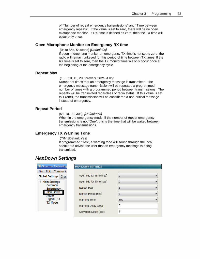
ManDown Settings
Chapter 3 Programming 23
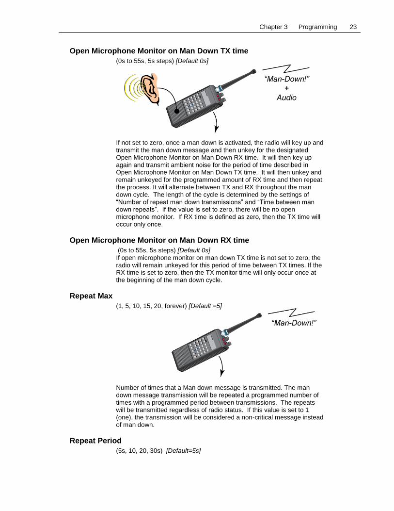
Open Microphone Monitor on Man Down TX time
(0s to 55s, 5s steps) [Default 0s] If not set to zero, once a man down is activated, the radio will key up and transmit the man down message and then unkey for the designated Open Microphone Monitor on Man Down RX time. It will then key up again and transmit ambient noise for the period of time described in Open Microphone Monitor on Man Down TX time. It will then unkey and remain unkeyed for the programmed amount of RX time and then repeat the process. It will alternate between TX and RX throughout the man down cycle. The length of the cycle is determined by the settings of “Number of repeat man down transmissions” and “Time between man down repeats”. If the value is set to zero, there will be no open microphone monitor. If RX time is defined as zero, then the TX time will occur only once.
Open Microphone Monitor on Man Down RX time
(0s to 55s, 5s steps) [Default 0s] If open microphone monitor on man down TX time is not set to zero, the radio will remain unkeyed for this period of time between TX times. If the RX time is set to zero, then the TX monitor time will only occur once at the beginning of the man down cycle.
Repeat Max
(1, 5, 10, 15, 20, forever) [Default =5] Number of times that a Man down message is transmitted. The man down message transmission will be repeated a programmed number of times with a programmed period between transmissions. The repeats will be transmitted regardless of radio status. If this value is set to 1 (one), the transmission will be considered a non-critical message instead of man down.
Repeat Period
(5s, 10, 20, 30s) [Default=5s]

Chapter 3 Programming 24
Repeated Man Down transmissions will be separated by a programmed delay period between transmissions.
Man Down TX Warning Tone
(Y/N) [Default No] If programmed “Yes”, a warning tone will sound through the local speaker at the end of the programmed warning delay to advise the user that a Man Down message will be transmitted if the radio is not up-righted within the programmed active delay time. Additionally, a warning tone will sound through the local speaker for each data transmission to advise the user that a man down message is being transmitted.
Man Down Warning Delay
(0 – 255 S) [Default 5 S] Once the board senses a man down situation, this timer begins to run. If the radio is not up righted within this period of time, a warning tone lasting 1 second is sounded. If the radio is up righted, the warning timer resets.
Man Down Activation Delay
(0 – 255 S)[Default 5 S] If the warning delay timer succeeds to complete its countdown and the warning tone is sounded, the activation delay timer begins to run. The activation delay timer is programmable 0 to 255 seconds. If the radio is not up righted within this period of time, the radio will key up and send a message to the base.
Audio Settings For the CIM-1200K, the Audio Control Pane allows you to designate the audio frequency and amplitude of critical warning tones and the PTT sidetone. Audio levels can be set between 0 and 255. Frequencies are available from drop-down lists.

Chapter 3 Programming 25

Chapter 3 Programming 26
Digital I/O Control As the CIM-1200K is a plug-in board, the necessary inputs and outputs are already connected to the correct pins on the interface connectors. The assignments required to complete the connectivity are as follows:
PAD FUNCTION SIGNAL
IN0 PTT Low
IN1 Emergency Low
IN3 Man Down Low
OUT0 Key High
OUT1 Critical Channel High
OUT2 Microphone Mute High
OUT4 Tone Control High
All Pull-ups should be set to “NO” and debounce for the inputs should be set to “10”. If the TX mode will be set to “Trunking” IN2 will also need to be programmed for “Trunk Acquired”. Be sure to program all unused inputs to “Disconnected”. If you do not program a radio button for “Emergency”, do not program an input for Emergency. There are five input ports and five output ports. All inputs and outputs required for your particular radio installation must be assigned to these ports. Input ports IN5 through IN8 are not available in the CIM-1200K device. Functions available for assignment to inputs are: Code0, Code1, Code2, Code3, PTT, Busy, Sleep, Emergency, Man Down, and Trunk Acquired.
Chapter 3 Programming 27
Individual output functions can be assigned to up to two output ports. Polarity can be assigned as Neg, Pos, or Pulse. Polarity of the signal in the input section refers to the polarity of the signal presented to the microprocessor. The microprocessor pull-up feature can be programmed on an individual I/O line basis. Debounce time is the time the line must remain active before the microprocessor recognizes it as a valid input. Functions available for assignment to outputs are: Key, Tone Control, TX Control, and Critical Channel. Polarity can be assigned as Neg or Pos. Polarity of the signal in the output section refers to the polarity of the signal generated by the microprocessor. The ultimate polarity achieved at the radio interface or solder pad will be determined by the output port selected as well as the jumpers being used for that output port.
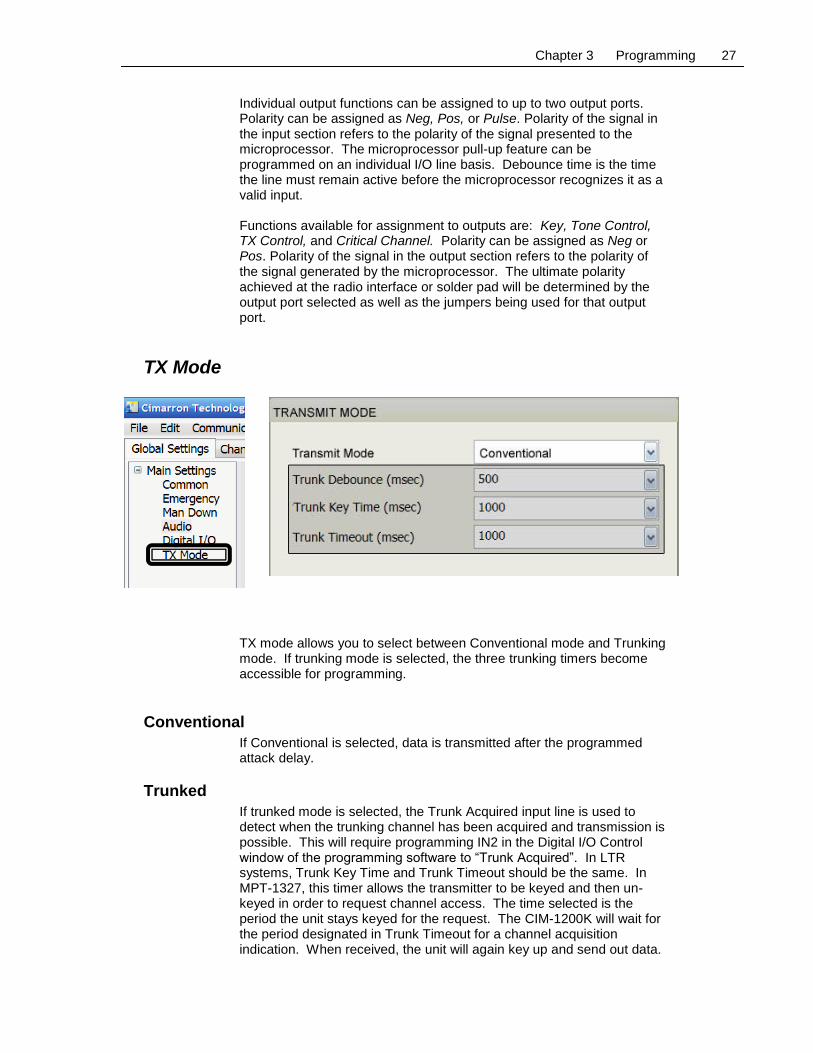
TX Mode
TX mode allows you to select between Conventional mode and Trunking mode. If trunking mode is selected, the three trunking timers become accessible for programming.
Conventional
If Conventional is selected, data is transmitted after the programmed attack delay.
Trunked
If trunked mode is selected, the Trunk Acquired input line is used to detect when the trunking channel has been acquired and transmission is possible. This will require programming IN2 in the Digital I/O Control window of the programming software to “Trunk Acquired”. In LTR systems, Trunk Key Time and Trunk Timeout should be the same. In MPT-1327, this timer allows the transmitter to be keyed and then un-keyed in order to request channel access. The time selected is the period the unit stays keyed for the request. The CIM-1200K will wait for the period designated in Trunk Timeout for a channel acquisition indication. When received, the unit will again key up and send out data.

Chapter 3 Programming 28
Trunk Debounce
Some trunking radios have channel acquired logic which pulses while attempting to be granted access and then remain in a state showing access is granted. For this reason, the line is programmable to set the debounce time so that pulsing is ignored. The unit will not transmit data until the specified time period has been exceeded.
Trunk Key Time
Trunk Key sets the time the unit is keyed while awaiting channel acquisition.
Trunk Time Out
Trunk Timeout sets the maximum amount of time that the unit will attempt to acquire a trunk. Once exceeded, the unit will quit attempts.
Channel Settings The figure on the next page shows the Channel Settings window. The maximum number of channels that can be designated is dependent on the number of device inputs that are programmed as code lines. One code line would provide you with two channels (line is either 0 or 1). Two code lines would give you four channels (00, 01, 10, 11) and so on. If “Respond to Channel Codes” in the Common menu is set to “No” then only channel one will be accessible.

Chapter 3 Programming 29

Chapter 3 Programming 30
Inv Type
This selection is not applicable for use with the CIM-1200K.
Fix Frq
This selection is not applicable for use with the CIM-1200K.
Min Frq
This selection is not applicable for use with the CIM-1200K.
Max Frq
This selection is not applicable for use with the CIM-1200K.
Min Dwl
This selection is not applicable for use with the CIM-1200K.
Max Dwl
This selection is not applicable for use with the CIM-1200K.
P/U INV
This selection is not applicable for use with the CIM-1200K.
ANI Type
“MDC” or “GE x” where x designates the GE Star® format. GE Star® formats are selectable from A through P. See page 37 for more details.
ANI Loc
None, Start, End, Both [Default = Start] If programmed “Start”, the ID will be transmitted when the user keys the radio. If programmed “End”, the ID will be transmitted when the user unkeys the radio. “Both” will provide ID transmissions at both the Start and the End.
PTT ID – EM ID – M/D ID
Generally, the PTT ID Emergency ID and the Man Down ID are the same; however, they could be programmed different if desired. In MDC-1200®, the valid ID range is from 0001 through DEEE. A radio ID cannot contain the character F nor can it begin with the character E as these are defined as wildcards. However, a radio can encode to a target ID containing these characters. In GE Star®, the actual maximum value depends on the GE Star® format type selected.
PTT MSG
In MDC-1200®, the default PTT message is 8001. In GE Star®, the default is “01”. Although these values are adjustable to permit worldwide system flexibility, they should never be changed except to accommodate documented system variances.

Chapter 3 Programming 31
TOT MSG
In MDC-1200®, the default TOT message is 8001. In GE Star®, the default is “09”. Although these values are adjustable to permit worldwide system flexibility, they should never be changed except to accommodate documented system variances.
EM MSG
In MDC-1200®, the default emergency message is 8000. In GE Star®, the default is “07”. Although these values are adjustable to permit worldwide system flexibility, they should never be changed except to accommodate documented system variances.
M/D MSG
In MDC-1200®, the default man down message is 8000. In GE Star®, the default is “0F”. Although these values are adjustable to permit worldwide system flexibility, they should never be changed except to accommodate documented system variances.
Group ID
This selection is not applicable for use with the CIM-1200K.
Mute Mode
This selection is not applicable for use with the CIM-1200K.
Crit ANI
If enabled, any PTT press during a critical cycle (e.g. emergency or man down) that would generate a PTT ANI will generate the critical message instead.
CRIT RVRT
(ONCE, ALL, NONE) [Default ONCE] Determines how the Critical Channel Revert output line reacts (if one is programmed in the I/O). “Once” means that the line momentarily goes low at the beginning of the critical cycle. “ALL” means that the line goes low for each critical data transmission within the cycle. “NONE” means that the Critical Channel Revert output is not activated on that channel.
C T
Unkey Courtesy Tone. If programmed “Yes”, a tone will be transmitted when the user unkeys to inform listeners that they may now transmit.
ACK
This selection is not applicable for use with the CIM-1200K.
Base ID
This selection is not applicable for use with the CIM-1200K.
Encryption Key
This selection is not applicable for use with the CIM-1200K.

Chapter 3 Programming 32
The MenuBar
Communications
Selections are available to send and receive settings from the device. You can select “All”, “Global” or “Channel” settings to be transferred. This feature makes reprogramming faster if changes have been made only in one section of the device. Additionally, you can select “Retrieve Device Information” which provides you with information relating to the firmware installed in the device. The Setup selection is used to define serial port settings.

Chapter 3 Programming 33
Channels
This selection is not applicable for use with the CIM-1200K.
Device
Open the device selection window and select CIM-1200K before performing programming.

Chapter 4 Operation 34
C H A P T E R 4 Operation
ANI-ID
ANI (Automatic Numeric Identification) provides for digital identification of a transmission initiated by a transmitter's microphone switch (“Press-To-Talk” or “PTT” switch). This “digital burst” can occur when the switch is first pressed, or when the switch is released, or at both times. The burst time for most identifiers is approximately 1/3 second and, if transmitted upon pressing the PTT switch, and the user immediately begins to talk, may obliterate one or two syllables of spoken speech. To overcome this annoyance, the Model CIM-1200K is programmable to produce the burst either at the beginning or at the end of the voice transmission, or at both times. To further guard against voice-syllable clipping, the user may program a “PTT Sidetone“. When programmed and interfaced to receiver audio, this feature will provide an audible tone during the beginning transmission of the ANI-ID burst to alert the operator that data is being transmitted.
Time-out-timer When a mobile or portable radio inadvertently remains keyed due to a stuck microphone switch, it generally means that the radio frequency is unusable for communications. Unfortunately, this activity is sometimes deliberately caused by a field operator. Whenever a microphone switch is held closed for more than the designated time-out-timer time the CIM-1200K will sound a local warning tone and send the ID of the offending radio. The unit can also be installed in a manner that will automatically open the key line until the microphone switch is released.
Emergency The Emergency feature is generally used by law enforcement, security agencies and fire departments to automatically signal a life-threatening situation where it is difficult, impossible, or impractical to use voice. The emergency message is also frequently used by business and industrial users to signal a critical situation, such as a mechanical failure, over or under temperature (pressure, etc.), or extraordinary event. The CIM-1200K allows for programming whether the message should be repeated and at what intervals and for how long. In addition, during the emergency cycle the microphone of the sending radio can be monitored, and can alternate between monitoring and allowing the channel to be used for voice communications.
Man-Down The Man-Down feature is primarily for use by law enforcement, security agencies, and fire departments. It also finds uses in business and industry where individuals can be overcome by toxic fumes, lack of oxygen, etc. The Man-Down ID transmission is generally initiated by closure of an optional tilt switch located within a hand-held radio when the radio is

Chapter 4 Operation 35
continuously tipped greater than 60 degrees from vertical. To guard against false “Man-Down” transmissions an initial pause of a few seconds is provided during which the closure must be constant. After this duration a short tone is produced via the radio's speaker. A second pause follows the tone to allow the radio to be placed in an upright position (in the event no actual “Man-Down” is occurring). Following the second pause the “Man-Down-ID” data burst is transmitted in the same manner as the “Emergency-ID”. The Man-Down mode also can include the microphone monitoring alternative. Transmission of a unique coding for the Man-Down message (in lieu of a general Emergency coding), and multiple choices of initiation, tone, and final pause times are available.
Status Status messages typically relate to the status of the field unit, such as “In Service”, “Out Of Service”, “On Break”, etc. and their appropriate meaning can be displayed at the decoding site equipped with a Cimarron Technologies C Plus decoder. The CIM-1200K is capable of transmitting status messages in lieu of the Man-Down, Emergency and PTT ANI as required.
Canned Messages
“Canned” messages handle such communications as “Request-To-Talk”, “Priority-Request-To-Talk”, “Repeat Last Transmission”, “Repeat Address”, “10-4”, “Roger”, and other routine requests and responses. Their appropriate meaning can be displayed at the decoding site equipped with a Cimarron Technologies C Plus decoder. The CIM-1200K is capable of transmitting canned messages in lieu of the Man-Down, Emergency and PTT ANI as required.
Multiple ANI format and ID Capability QuikWare programming software allows the CIM-1200K to be configured with multiple ANI personalities that are defined by the user under the Channel Settings tab. Personalities are selected by changing the states of code lines assigned to device inputs. The maximum number of channels that can be designated is dependent on the number of device inputs that are programmed as code lines. One code line would provide you with two channels (line is either 0 or 1). Two code lines would give you four channels (00, 01, 10, 11) and so on. If “Respond to Channel Codes” in the Common menu is set to “No” then only channel one will be accessible.


Chapter 5 Technical Information 37
C H A P T E R 5 Technical Information
GE Star® Format Selections
Radio systems using GE Star® can define the T1, T2 and S1 bits to have different values or various meanings. Industry-wide, there are sixteen accepted variants with Format “B” being the industry defacto standard. The CIM-1200K is programmable for any of the sixteen variants.
Format Definitions The following table defines the sixteen GE Star® formats.
Format Description T1 T2 S1 Comments
A IDs to 2047 (1st 11 bits). X X X T1, T2, and S1 ignored
B IDs to 16383 (14 bit ID) 8192 4096 2048 Expanded-ID STAR #1.
C IDs to 16383 (14 bit ID) 4096 8192 2048 GE-STAR #3.
D IDs to 16383 (14 bit ID) 4096 2048 8192 Compatible with GE-STAR #4
E IDs to 4095 (12 bit ID, T2 =“0”) 2048 M0 X GE-STAR #1. T2 = “0” for Mobile.
F IDs to 4095 (12 bit ID, T2=“1”) 2048 P1 X GE-STAR #1. T2 = “1” for Portable.
G IDs to 8191 (13 bit ID, T2 =“0”) 4096 M0 2048 GE-STAR #2. T2 = “0” for Mobile.
H IDs to 8191 (13 bit ID, T2 =“1”) 4096 P1 2048 GE-STAR #2. T2 = “1” for Portable.
I IDs to 4095 (12 bit ID),
Tags=“00”
0 0 2048 System “0”
J IDs to 4095 (12 bit ID),
Tags=“01”
0 1 2048 System “1”.
K IDs to 4095 (12 bit ID),
Tags=“10”
1 0 2048 System “2”.
L IDs to 4095 (12 bit ID),
Tags=“11”
1 1 2048 System “3”.
M - P IDs to 2047 (11 bit ID) X Identical to I - L with capability only to
program IDs to max of 2047.
Value Assignment Description
8192 If bit is set, add 8192 to ID
4096 If bit is set, add 4096 to ID
2048 If bit is set, add 2048 to ID
M0 If the bit is not set, originator is a Mobile
P1 If the bit is set, originator is a Portable
X This bit is ignored
For system types I through P, the C Plus decoder looks for a match in the T1 and T2 bits. If the bits match then the C Plus decoder will react to the received message. If not, the message is ignored. This is for communications systems that have multiple unrelated users so that different users do not see ID’s from other users.
GE Star® Message Descriptions
The GE Star® bits designated S2, S3, S4 and M1 through M4 are used to code various messages. The CIM-1200K can be programmed so that different message types are transmitted for PTT ANI, Emergency ANI, Man-Down and TOT ANI. The desired star code is selected in
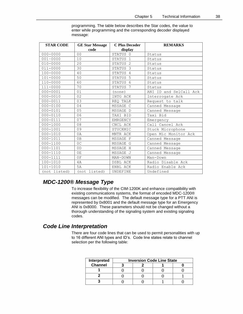
Chapter 5 Technical Information 38
programming. The table below describes the Star codes, the value to enter while programming and the corresponding decoder displayed message:
STAR CODE GE Star Message
code
C Plus Decoder
display
REMARKS
000-0000 00 STATUS 0 Status
001–0000 10 STATUS 1 Status
010-0000 20 STATUS 2 Status
011-0000 30 STATUS 3 Status
100-0000 40 STATUS 4 Status
101-0000 50 STATUS 5 Status
110-0000 60 STATUS 6 Status
111-0000 70 STATUS 7 Status
000-0001 01 (none) ANI ID and SelCall Ack
000-0010 02 INTG ACK Interrogate Ack
000-0011 03 REQ TALK Request to talk
000-0100 04 MSSAGE C Canned Message
000-0101 05 MSSAGE D Canned Message
000-0110 06 TAXI BID Taxi Bid
000-0111 07 EMRGENCY Emergency
000-1000 08 CNCL ACK Call Cancel Ack
000-1001 09 STUCKMIC Stuck Microphone
000-1010 0A MNTR ACK Open Mic Monitor Ack
000-1011 0B MSSAGE F Canned Message
000-1100 0C MSSAGE G Canned Message
000-1101 0D MSSAGE H Canned Message
000-1110 0E MSSAGE J Canned Message
000-1111 0F MAN-DOWN Man-Down
100-1010 4A DSBL ACK Radio Disable Ack
101-1010 5A ENBL ACK Radio Enable Ack
(not listed) (not listed) UNDEFINE Undefined
MDC-1200® Message Type To increase flexibility of the CIM-1200K and enhance compatibility with existing communications systems, the format of encoded MDC-1200® messages can be modified. The default message type for a PTT ANI is represented by 0x8001 and the default message type for an Emergency ANI is 0x8000. These parameters should not be changed without a thorough understanding of the signaling system and existing signaling codes.
Code Line Interpretation There are four code lines that can be used to permit personalities with up to 16 different ANI types and ID’s. Code line states relate to channel selection per the following table:
Interpreted Channel
Inversion Code Line State
3 2 1 0
1 0 0 0 0 2 0 0 0 1 3 0 0 1 0

Chapter 5 Technical Information 39
4 0 0 1 1 5 0 1 0 0 6 0 1 0 1 7 0 1 1 0 8 0 1 1 1 9 1 0 0 0
10 1 0 0 1 11 1 0 1 0 12 1 0 1 1 13 1 1 0 0 14 1 1 0 1 15 1 1 1 0 16 1 1 1 1
This capability is not currently supported by Kenwood radio firmware. There are, however solder pads on the back of the CIM-1200K that can be configured to accept up to three of these code inputs which would permit up to 8 personality selections by using external switches. In this table, “Code Line State” refers to logical inputs after QuikWare Digital I/O crossbar polarity has been applied to physical inputs (Neg polarity assigned).
Chapter 5 Technical Information 40
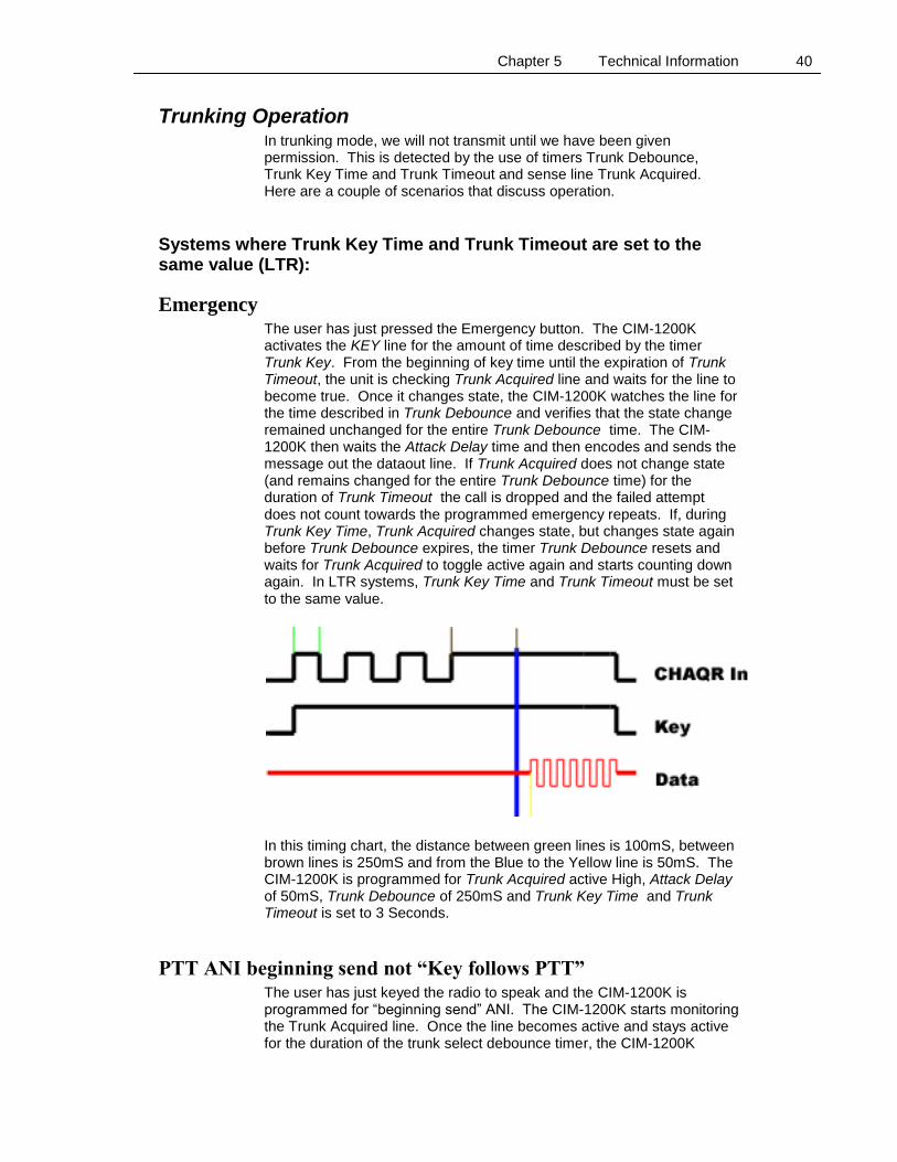
Trunking Operation In trunking mode, we will not transmit until we have been given permission. This is detected by the use of timers Trunk Debounce, Trunk Key Time and Trunk Timeout and sense line Trunk Acquired. Here are a couple of scenarios that discuss operation.
Systems where Trunk Key Time and Trunk Timeout are set to the same value (LTR):
Emergency The user has just pressed the Emergency button. The CIM-1200K activates the KEY line for the amount of time described by the timer Trunk Key. From the beginning of key time until the expiration of Trunk Timeout, the unit is checking Trunk Acquired line and waits for the line to become true. Once it changes state, the CIM-1200K watches the line for the time described in Trunk Debounce and verifies that the state change remained unchanged for the entire Trunk Debounce time. The CIM-1200K then waits the Attack Delay time and then encodes and sends the message out the dataout line. If Trunk Acquired does not change state (and remains changed for the entire Trunk Debounce time) for the duration of Trunk Timeout the call is dropped and the failed attempt does not count towards the programmed emergency repeats. If, during Trunk Key Time, Trunk Acquired changes state, but changes state again before Trunk Debounce expires, the timer Trunk Debounce resets and waits for Trunk Acquired to toggle active again and starts counting down again. In LTR systems, Trunk Key Time and Trunk Timeout must be set to the same value.
In this timing chart, the distance between green lines is 100mS, between brown lines is 250mS and from the Blue to the Yellow line is 50mS. The CIM-1200K is programmed for Trunk Acquired active High, Attack Delay of 50mS, Trunk Debounce of 250mS and Trunk Key Time and Trunk Timeout is set to 3 Seconds.
PTT ANI beginning send not “Key follows PTT” The user has just keyed the radio to speak and the CIM-1200K is programmed for “beginning send” ANI. The CIM-1200K starts monitoring the Trunk Acquired line. Once the line becomes active and stays active for the duration of the trunk select debounce timer, the CIM-1200K

Chapter 5 Technical Information 41
activates the Key line, waits the attack delay and then sends the PTT ANI and then deactivates the Key line. The radio remains keyed because the user is still pressing the PTT button. If the Trunk Acquired line does not become active and remain active for the duration of the trunk select debounce timer, by the end of the Trunk Time out, the call is dropped.
PTT ANI end send not “Key follows PTT” The user has just keyed the radio to speak and the CIM-1200K is programmed for “end send” ANI. The CIM-1200K waits for the user to unkey the radio. The CIM-1200K then activates the KEY line for the amount of time described by the timer Trunk Key. From the beginning of key time until the expiration of Trunk Timeout, the unit is checking Trunk Acquired line and waits for the line to become true. Once it changes state, the CIM-1200K watches the line for the time described in Trunk Debounce and verifies that the state change remained unchanged for the entire Trunk Debounce time. The CIM-1200K then waits the Attack Delay time and then encodes and sends the message out the dataout line. If Trunk Acquired does not change state (and remain changed for the entire Trunk Debounce time) for the duration of Trunk Timeout the call is dropped. If, during Trunk Key Time, Trunk Acquired changes state, but changes state again before Trunk Debounce expires, the timer Trunk Debounce resets and waits for Trunk Acquired to toggle active again and starts counting down again.
PTT ANI beginning send with “Key follows PTT” The user has just keyed the radio to speak and the CIM-1200K is programmed for “beginning send” ANI. The CIM-1200K activates the key line and starts monitoring the Trunk Acquired line. Once the line becomes active and stays active for the duration of the trunk select debounce timer, the CIM-1200K waits the attack delay and then sends the PTT ANI. The Key line remains active until the user releases the PTT button. If the Trunk Acquired line does not become active within the time set in Trunk Timeout, the key line relaxes and the call is dropped. The user must rekey the radio to make another attempt. The value of Trunk Key (which is the same as the value of Trunk Timeout) is ignored.
PTT ANI end send with “Key follows PTT” The user has just keyed the radio to speak and the CIM-1200K is programmed for “end send” ANI. The CIM-1200K activates the key line and continues monitoring the PTT line. Once the line becomes inactive, the CIM-1200K sends the PTT ANI and then unkeys the radio. The values of Trunk Key Time, Trunk Timeout and Trunk Debounce time are ignored.
Systems where Trunk Key Time and Trunk Timeout are not set to the same value (MPT and others):
Emergency The user has just pressed the Emergency button. The CIM-1200K activates the KEY line for the amount of time described by the timer Trunk Key. From the beginning of key time until the expiration of Trunk

Chapter 5 Technical Information 42
Timeout, the unit checks Trunk Acquired line and waits for the line to become true. Once it changes state, the CIM-1200K watches the line for the time described in Trunk Debounce and verifies that the state remains unchanged for the entire Trunk Debounce time. It then rekeys, waits the attack delay and sends out data. If Trunk Acquired does not change state for the duration of Trunk Timeout the call is dropped and the failed attempt does not count towards the programmed emergency repeats.
In this timing chart, the distance between green lines is 100mS, between blue lines is 50mS and between brown lines is 200mS. The CIM-1200K is programmed for Trunk Acquired active High, Attack Delay of 200mS, Trunk Debounce of 50mS, Trunk Key Time of 100mS and Trunk Timeout to 3 Seconds.
PTT ANI beginning send not “Key follows PTT” The user has just keyed the radio to speak and the CIM-1200K is programmed for “beginning send” ANI. If the values of Trunk Key Time and Trunk Timeout are not the same, the CIM-1200K starts monitoring the Trunk Acquired line. Once the line becomes active, the CIM-1200K begins monitoring the PTT line. When the PTT line becomes active, and the Trunk Acquired line is still active, the CIM-1200K activates the Key line, waits the attack delay and then sends the PTT ANI and then deactivates the Key line. The radio remains keyed because the user is still pressing the PTT button. If the Trunk Acquired line and the PTT line do not both become active within the programmed Trunk Timeout time, the call is cancelled.
PTT ANI end send not “Key follows PTT” The user has just keyed the radio to speak and the CIM-1200K is programmed for “end send” ANI. If the values of Trunk Key Time and Trunk Timeout are not the same, the CIM-1200K monitors the Trunk acquired line and the PTT line. When both lines become active, the CIM-1200K waits for the PTT line to become inactive and then The CIM-1200K activates the KEY line for the amount of time described by the timer Trunk Key. From the beginning of key time until the expiration of Trunk Timeout, the unit checks Trunk Acquired line and waits for the line to become true. Once it changes state, the CIM-1200K watches the line for the time described in Trunk Debounce and verifies that the state remains unchanged for the entire Trunk Debounce time. It then rekeys, waits the attack delay and sends out data. If Trunk Acquired does not change state for the duration of Trunk Timeout the call is dropped

Chapter 5 Technical Information 43
PTT ANI beginning send with “Key follows PTT” The user has just keyed the radio to speak and the CIM-1200K is programmed for “beginning send” ANI. The values of Trunk Key Time and Trunk Timeout are not the same. The CIM-1200K key line follows the action of the radio PTT line. The CIM-1200K starts monitoring the Trunk Acquired line. Once the line becomes active the CIM-1200K waits for the PTT line to again become active, waits the attack delay and then sends the PTT ANI. The Key line follows the action of the radio PTT line. If the radio PTT line does not become active within Trunk Timeout of when the Trunk Acquired line became active, the call is dropped.
PTT ANI end send with “Key follows PTT” The user has just keyed the radio to speak and the CIM-1200K is programmed for “end send” ANI. The values of Trunk Key Time and Trunk Timeout are not the same. The CIM-1200K key line follows the action of the radio PTT line. The CIM-1200K starts monitoring the Trunk Acquired line. Once the line becomes active the CIM-1200K waits for the PTT line to again become active, then waits for the line to relax. When the radio PTT line relaxes, the CIM-1200K Key line remains active and sends the PTT ANI. The Key line then relaxes. If the radio PTT line does not become active within Trunk Timeout of when the Trunk Acquired line became active, the call is dropped.
Component Location
Chapter 5 Technical Information 44
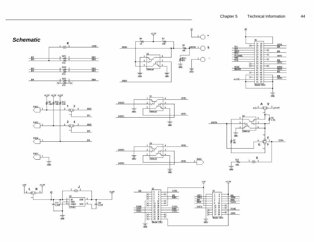
Schematic
Chapter 6 Troubleshooting 45
C H A P T E R 6 Troubleshooting
Installation Hints The CIM-1200K must be programmed with your desires before it will work in your system. The CIM-1200K will be keying the associated transmitter and injecting audio into the radio. It is very important to adjust data out to ensure the correct deviation level. The deviation level should be just marginally below that of voice. Keep in mind that most transmitters have limiter circuitry. Limiter circuits ensure that the radio will never over-deviate and violate FCC rules. The limiter does this by clipping the transmit audio. The output of the CIM-1200K must be adjusted to a point just below where limiter clipping occurs. If the limiter is allowed to function, the data will be distorted. Be sure to only program inputs for functions that will be used. Unused inputs must be programmed for “Disconnected” to avoid unstable results.
Isolating System Problems Today’s modern communication systems take advantage of many available resources. Voters, repeaters, various trunking protocols, scramblers and innumerable other devices make passing data substantially more difficult than it was in the “Simplex” days. Timing is very important. If you have system problems, the first place to spend your energies is with timing issues. Check attack delay in repeater systems. Start with a long delay that gives you 100% decode and then shorten it up. If you have trunking system problems using the CIM-1200K, review the trunking information located on page 40 of this manual.
Equipment Problems Radio keys and stays keyed If the radio sends ANI data and then stays keyed even after releasing the PTT button, verify the condition of jumper K on the CIM-1200K and the programming parameter “Key follows PTT”. If you have “Key Follows PTT” enabled, jumper K must not be connected. Radio keys up but stays keyed only for duration of ANI This symptom is usually caused by incorrect conditions of the “Key follows PTT” parameter. ANI goes out at “End” regardless of programming This symptom is usually caused by the “PTT Sense” being programmed opposite of how it should be or the voltage swing is insufficient. Use an O’scope to measure the level at the yellow (PTT) line when at rest and then when active (Keyed). The line should rest above 1.9VDC and go low when keyed if active low. It should rest below 0.9VDC and go above 1.9VDC when active if active high. ID Decoded is not the same as programmed

Chapter 6 Troubleshooting 46
This occurs when the unit is in GE Star® mode and the CIM-1200K “format” is not set the same as the decoder. See page 37 for details.

Chapter7 Product Support 47
C H A P T E R 7 Product Support
If you have any questions or comments about Cimarron products, please make use of our technical support hotline at (760) 738-3285. Cimarron Technologies Corporation 934 South Andreasen Drive, Suite G Escondido, CA 92029 Technical Support Hot-Line (760) 738-3285 [email protected] www.cimtechcorp.com
WARRANTY
Cimarron Technologies Corporation warrants this product to be free from defects in material and
workmanship for a period of three years from date of shipment. If a malfunction occurs due to defective
material or workmanship, the product will be repaired or replaced (Cimarron's discretion) without charge
if returned to the factory
This warranty does not apply to any failure or damage caused by accident, neglect, unreasonable use,
improper installation, or to alterations or modifications to the unit. Nor does the warranty extend to damage
incurred by force majeure (natural causes) such as lightning, fire, floods, or other such catastrophes, nor to
damage caused by environmental extremes, power surges and/or transients
Cimarron Technologies Corporation makes no other warranty, either expressed or implied, with respect to
this product. Cimarron Technologies Corporation specifically disclaims the implied warranties of
merchantability and fitness for a particular purpose. Some states or provinces do not allow limitations on
how long an implied warranty lasts, so the above limitation or exclusion may not apply to you.
The remedies provided herein are customer's sole and exclusive remedies. In no event shall Cimarron
Technologies Corporation be liable for any lost profits, direct, indirect, special, incidental, or
consequential damages, whether based on contract, tort, or any other legal theory
.

Appendix A Quick Start Guide for QuikWare Software 48
A P P E N D I X A Quick Start Guide for QuikWare Software
You will have received an installation program called QuikWare.exe with an icon like this: The program is distributed either on a CD or can be downloaded from our website www.cimtechcorp.com. Click the Icon and follow the installation directions. The routine will check your computer system and install required components. When the installation is complete, you will need to import the license. Start QuikWare and on the menu bar, select File and then click on “Import License”. You will be asked for the location of the .cimlicense file. This will be either on your CD, or if you downloaded the QuikWare, Cimarron will email you your license at time of purchase.
QuikWare software is used to program the CIM-1200/2200 board with the Cimarron QuikSync USB cable. Attach the cable as shown using the three “grabbers”.
Now, go to “Device” in the menubar and select CIM-1200 or CIM-2200.
Configure the QuikWare to access the correct communications port on the computer. Select “Communications” and “Setup” and select the COM port that your programming cable is connected. Refer to the Programming chapter of the CIM manual for information regarding available programming parameters. Make all required changes. Write the parameters to the board. From the menu bar, select “communications”. You can choose to “Send All” or if you only changed settings in Global or Channel areas, “Send Global” or “Send Channel”.
Index 49
INDEX
.
.cimlicense file .......................................................... 15
A
ANI location ............................................................. 30
ANI repeat timer ....................................................... 20
ANI type ................................................................... 30
Attack delay ........................................................ 19, 45
Audio settings ........................................................... 24
Automatic Numeric Identification ............................ 34
C
Canned messages ...................................................... 35
Capabilities ................................................................. 6
Channel settings ........................................................ 28
Cimarron Technologies QuikWare ........................... 15
Code line interpretation ............................................. 39
Code lines ................................................................. 28
Communications ....................................................... 32
Conventional mode ................................................... 27
Critical ANI .............................................................. 31
Critical channel revert ............................................... 31
D
Data deviation ............................................... 13, 20, 45
Device ....................................................................... 18
Device selection ........................................................ 33
Digital I/O control ..................................................... 26
E
Emergency ................................................................ 34
Emergency message .................................................. 31
Emergency message repeat ....................................... 22
Emergency open microphone monitor ...................... 22
Emergency repeat period .......................................... 22
Emergency settings ................................................... 21
Emergency TX warning tone .................................... 22
G
GE Star format type .................................................. 37
GE Star message descriptions ................................... 37
I
Import license ........................................................... 15
Input ports ................................................................ 26
Installation .................................................................. 9
Installation hints ....................................................... 45
J
Jumpers .............................................................. 11, 12
K
Key follows PTT ................................................ 20, 45
KPG-101D software ................................................. 11
KPG-89D software ..................................................... 9
KPG-95D software ................................................... 11
L
LTR systems ............................................................ 27
M
Man down ................................................................ 34
Man down activation delay ...................................... 24
Man down message repeat ....................................... 23
Man down open microphone monitor ...................... 23
Man down repeat period ........................................... 24
Man down settings ................................................... 23
Man down TX warning tone .................................... 24
Man down warning delay ......................................... 24
Mandown message ................................................... 31
MDC-1200 message type ......................................... 38
Microphone monitoring ............................................ 35
MPT-1327 ................................................................ 27
Multiple ANI personalities ....................................... 35
N
Non-critical ........................................................ 22, 23
Number of repeat emergency transmissions ............. 22
Number of repeat man down transmissions.............. 23
O
Open microphone monitor on emergency ................ 21

Index 50
Output ports .............................................................. 26
P
Product support ......................................................... 47
Programming ............................................................ 15
Programming software .............................................. 16
PTT input .................................................................. 45
PTT message ............................................................. 30
PTT sidetone ............................................................. 34
Q
QuikWare .................................................................. 16
R
Repeaters .................................................................. 45
Respond to channel codes ................................... 21, 35
Retrieve device information ...................................... 32
S
Setup ......................................................................... 32
Sidetone with PTT ANI ............................................ 20
Software license ........................................................ 15
Solder pads................................................................ 13
Specifications .............................................................. 8
Startup delay ............................................................. 19
Status messages......................................................... 35
System problems ....................................................... 45
T
Time out timer .................................................... 20, 34
Timing ...................................................................... 45
TK-2170/3170 .......................................................... 10
TK-2180/TK-3180 ..................................................... 9
TK-5210 ................................................................... 11
TK-5710 ................................................................... 11
TK-7180/TK-8180 ..................................................... 9
TOT message ........................................................... 31
Trunk debounce ........................................................ 28
Trunk key time ......................................................... 28
Trunk timeout ........................................................... 28
Trunking mode ................................................... 27, 40
TX data level ............................................................ 20
TX mode .................................................................. 27
U
Unkey courtesy tone ................................................. 31
USB programming cable .......................................... 16
V
Voice-syllable clipping ............................................ 34
W
Warranty................................................................... 47