Embed Size (px)
Citation preview
Model Checking Industrial Robot Systems
Markus Weißmann1, Stefan Bedenk2, Christian Buckl3, and Alois Knoll1
1 Technische Universitat Munchen, Fakultat fur InformatikBoltzmannstrasse 3, 85748 Garching, Germany
[email protected] AUDI AG
85057 Ingolstadt, [email protected]
3 fortiss GmbHGuerickestr. 25, 80805 Munchen, Germany
Abstract. Modern production plants are highly automated complexsystems consisting of several robots and other working machines. Er-rors leading to damage and stop of production are extremely expensiveand must be avoided by all means. Hence, the state of practice is to testcontrol programs in advance which implies high effort and comes withhigh costs. To increase the confidence into the control systems and toreduce the necessary effort, this paper proposes to use model checkingto verify certain properties. It presents a compiler that can transformindustrial robot programs into PROMELA models. Since the statementsof the robot programming language can not be mapped directly intoPROMELA statements, we apply compiler optimization techniques toclose the semantic gap. In case of a specification violation the trace ismapped to the original context so that the robot programmer can re-construct the problem. As a case study we applied the tool to verify theabsence of collisions and deadlocks. We were able to detect one deadlockin a car-body welding station with 9 robots, correct the program andverify the correctness of the resulting system.
Keywords: model checking, abstract interpretation, industrial robots,distributed systems
1 Introduction
Modern production plants are highly automated, complex systems. They use in-dustrial robots for lifting, welding, bonding and other tasks for which the robotsmay have to work in the same area. Design errors resulting e. g. in collisionsor deadlocks can lead to downtime of the plant which are extremely expensive.This is especially true for modern production plants that use just in time pro-duction; in these systems each industrial robot system easily becomes a singlepoint of failure the outage of which can quickly result in an outage of the wholeproduction line.
2
To address this problem upfront, the control programs are tried to be keptas simple as possible. This approach is counteracted upon by the necessity formore and more dynamic production processes. For example car body productionplants are used to produce different variants of cars, e. g. a fastback and stationwagon, different numbers of doors, etc. This flexibility has to be provided by thecontrol programs.
Virtual commissioning is an approach to find problems in the programmingupfront, before the plant is built. Most commonly it is carried out as a computersimulation of the industrial robot system. Different levels of detail on the physicalpart of the plant are used, reaching from a plain emulation of the programs to3D simulations with a hardware-in-the-loop setup of the controllers. Using thissimulation the programs can be tested. However this approach implies greattesting effort and does not guarantee the correctness of the system.
To target this issue, this paper proposes the use of model checking techniquesto verify the correctness of the system with respect to certain properties. Thisapproach has the advantage that it can prove the absence of errors – in contrastto tests. To apply model checking on the control programs, they must first betransformed into a formal model. Since engineers without a background in for-mal verification should be able to apply this method, too, a manual creation ofthis formal model is not feasible. An automated translation solves this problemand also the need to keep the formal model and the original robot programssynchronized.
This paper presents a compiler that can transform industrial robot programsinto PROMELA models as input for the SPIN model checker [12]. Since thestatements of the robot programming language can not be mapped directly intoPROMELA statements, we apply compiler optimization techniques to close thesemantic gap. To verify certain properties our tool extends the PROMELA codewith assertions. The engineer can add further properties in form of linear tem-poral logic (LTL) formulas. To simplify the formulation of these LTL formulas,LTL patterns for each property to verify are provided.
If SPIN detects a violation of one property, it generates an error trace leadingto the violation in the PROMELA model. To help a robot programmer under-stand the result of the analysis, the presented tool-chain provides a projectionof the error-trace in the model back to the original robot programs.
As a case study we applied the tool to verify the absence of collisions anddeadlocks. We were able to detect one deadlock in a car-body welding stationwith 9 robots, correct the robot control programs and verify the correctness ofthe resulting system.
The structure of the paper is as follows: Section 2 contains preliminarieson the problem and gives an overview of previous work; Section 3 discussesthe problem details; our solution is presented in section 4. The results of ouranalysis of two industrial robot systems can be found in section 5. We concludein section 6.
3
2 Background
An industrial robot system typically consists of a programmable logic controller(PLC) and several robots. The PLC and the robots are running the controlprograms. They control further devices like welding guns and riveting systems,which are not programmable devices; they are either controlled by the PLC or arobot. The PLC controls the system as a whole; it tells the robots which controlprogram to use for the current process. The PLC is also the master hub of theindustrial robot system: All up-stream communication from the system devicesis routed through the PLC; hence the network topology of the system is a tree.
To reduce costs, increase reliability and to shorten product cycles, manufac-turers want to have a high quality control software before starting the commis-sioning process. The current approach is to model the industrial robot systemin a hardware-in-the-loop (HIL) simulation, the so-called virtual commissioning.This method allows testing up-front, but finding bugs is still a tedious task andthe absence of bugs can not be shown. To address this problem, we want tointroduce formal verification to analyze the control software.
Several approaches to formal verification for embedded systems [7] and morespecifically industrial control systems using PLCs [19] are available. A commonsolution is to use model checking, e. g. with the SPIN model checker; otherapproaches include abstract interpretation [17] or manually created, computerbased proofs [18].
A basic solution for making use of a model checker is to manually create amodel of the PLC program, then use a model checker to verify it [14]. As ourgoal includes providing a system for non-experts in verification, manually cre-ated proofs are not a suitable option. More advanced approaches use automatictranslation from PLC programs in Instruction List (IL) [4, 15] or in SequentialFunction Charts (SFC) [1]. This method is suitable not only for PLC program-ming languages: The Java PathFinder can be used to verify Java programs [11]by compiling them to PROMELA, the modeling language of SPIN. Bandera fol-lows a similar approach and can analyze Java programs; it uses an optimizingcompiler to translate them to either a Spin or NuSMV model [5]. This has alsobeen done with programs written in C with a mixed-mode translation; the pro-grams are compiled and combined with manually written system calls [8]. Carehas to be taken that the extraction provides a faithful model of the system [10].
A remaining problem of the automatic model extraction [13] is that there isstill the need for an expert to interpret the resulting trace in case of an error.This problem can be solved by creating highly specialized model checkers thatcan use the original program as model, e. g. in C [2] and in PLC/IL language[16].
Abstract interpretation has been used on modeling languages [9] and also onPLC/IL programs to perform range analysis [3].
Our approach uses model extraction on the robot programs, while the PLCtask is generated. The resulting model consisting of multiple processes can thenbe verified. In case an error is found in the model, the resulting error-trace is
4
projected back to the original context. Example properties that can be checkedare deadlocks, collisions and kill-switch violations.
3 Problem Statement
In this section we provide an overview of the system we want to verify. We willdiscuss the robot programming language and the interlock algorithm providedby the PLC.
An industrial robot system typically consists of up to 10 robots and a PLCwhich communicate over field bus. This distributed system shares common re-sources in the form of physical space that can be occupied by a single robotonly. If more than one robot tries to use the same area at the same time, thisbehavior leads to a collision of the robots. To avoid this behavior the robots usea software locking mechanism with the PLC as central arbiter.
Before an industrial robot system’s start of production (SOP) its behavior istested to assure it is working correctly, e. g. it is free of collisions. This testing istedious, expensive and can not guarantee the absence of errors.
Our goal is to provide a system that:
– does not require much effort to set up for a concrete industrial robot system– can quickly verify the absence of certain programming errors– is easy to use for a robot programmer, i. e. does not require expertise in
formal verification
3.1 Robot Programming Language
The robot control language (VKRC) is an imperative language. Our compilerhandles the core language which is sufficient to detect the faults we want to find.For simplicity we will refer to this subset as VKRC. This core language includesassignments, control flow commands and movement commands for the roboticarm.
Variables The language only has boolean expressions. Depending on their type,variables can either store a boolean value or a boolean expression. Variables neednot be declared, the set of variables is fixed. There are local variables, outgo-ing, incoming and symbolic variables; variables have a one-character prefix thatdetermines their type followed by a natural number (see table 1). The outgoingand incoming variables are for communication with the PLC: Their contents aresent to the PLC by the robots runtime system, received from it respectively. Thiscommunication is completely transparent to the robot programmer. The sym-bolic variables can store an expression which gets evaluated when the symbolicvariable is read. The kill-switch condition variable is a special purpose symbolicvariable: When moving, the robot continuously checks this variable and triggersan emergency stop if the stored expression evaluates to false.
5
Variable Semantics
Fn Local variableAn Outgoing variableEn Incoming variable (read-only)Mn Symbolic variable (local)FB SPS Kill-switch condition (only on left-hand side)
Table 1. Types of variables in VKRC (n ∈ N+)
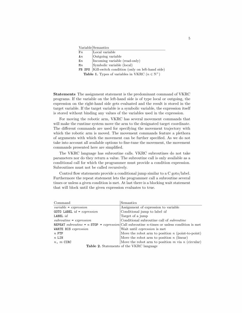
Statements The assignment statement is the predominant command of VKRCprograms. If the variable on the left-hand side is of type local or outgoing, theexpression on the right-hand side gets evaluated and the result is stored in thetarget variable. If the target variable is a symbolic variable, the expression itselfis stored without binding any values of the variables used in the expression.
For moving the robotic arm, VKRC has several movement commands thatwill make the runtime system move the arm to the designated target coordinate.The different commands are used for specifying the movement trajectory withwhich the robotic arm is moved. The movement commands feature a plethoraof arguments with which the movement can be further specified. As we do nottake into account all available options to fine-tune the movement, the movementcommands presented here are simplified.
The VKRC language has subroutine calls. VKRC subroutines do not takeparameters nor do they return a value. The subroutine call is only available as aconditional call for which the programmer must provide a condition expression.Subroutines must not be called recursively.
Control flow statements provide a conditional jump similar to a C goto/label.Furthermore the repeat statement lets the programmer call a subroutine severaltimes or unless a given condition is met. At last there is a blocking wait statementthat will block until the given expression evaluates to true.
Command Semantics
variable = expression Assignment of expression to variableGOTO LABEL id = expression Conditional jump to label idLABEL id Target of a jumpsubroutine = expression Conditional subroutine call of subroutineREPEAT subroutine = n STOP = expression Call subroutine n-times or unless condition is metWARTE BIS expression Wait until expression is metn PTP Move the robot arm to position n (point-to-point)n LIN Move the robot arm to position n (linear)n, m CIRC Move the robot arm to position m via n (circular)
Table 2. Statements of the VKRC language
6
Boolean Expression Semantics
expression & expression Logical and of two expressionsexpression + expression Logical or of two expressions! expression Logical inversion of expression( expression ) Brackets for changing order of precedencevariable See table 1AUS false (literally off )EIN true (literally on)
Table 3. Boolean functions in VKRC
Communication The robot uses the input and output variables to communi-cate with the PLC; this communication is handled by a field bus. To the robotprogrammer this communication is completely transparent, to him the robotappears to have a shared memory with the PLC.
The PLC can either handle the incoming and outgoing variables of the robotwith a PLC program, or just map the outgoing variables to incoming ones ofanother robot.
3.2 Interlock algorithm
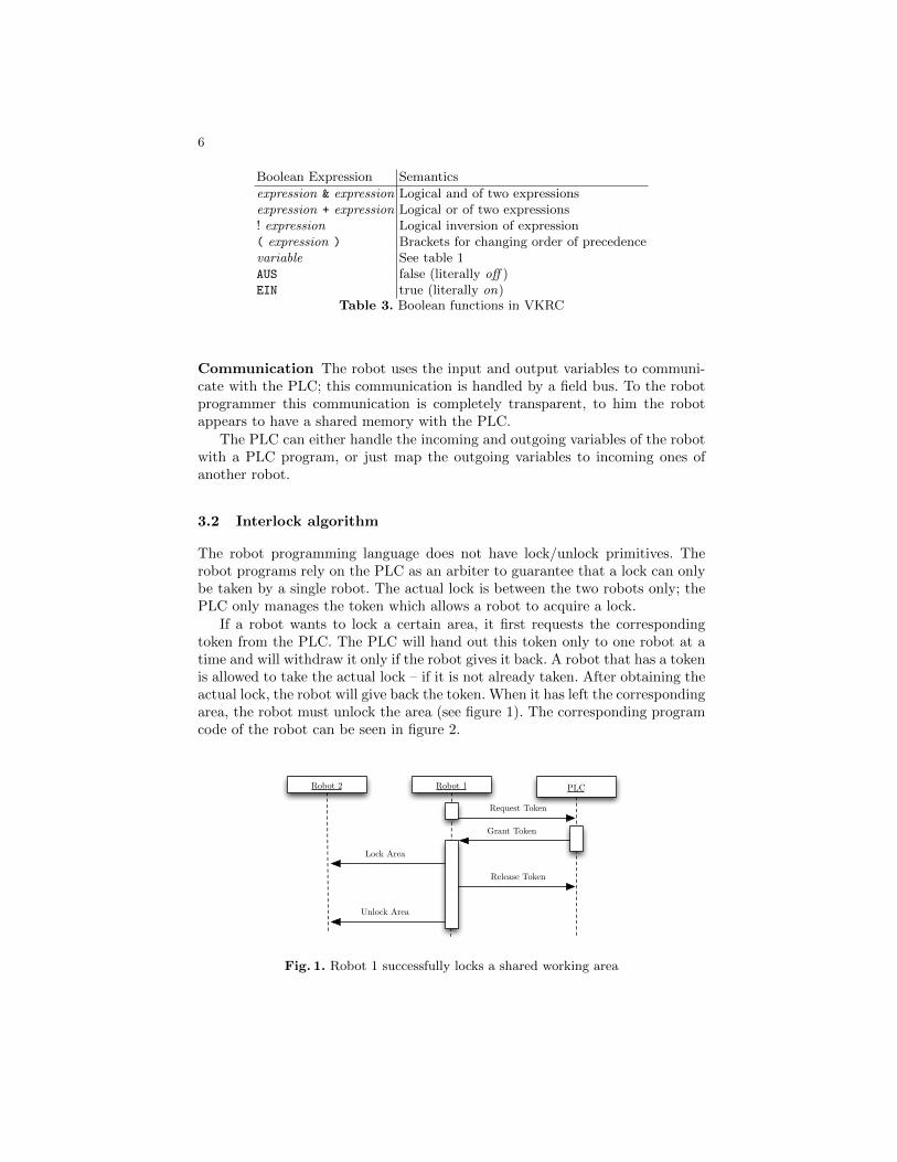
The robot programming language does not have lock/unlock primitives. Therobot programs rely on the PLC as an arbiter to guarantee that a lock can onlybe taken by a single robot. The actual lock is between the two robots only; thePLC only manages the token which allows a robot to acquire a lock.
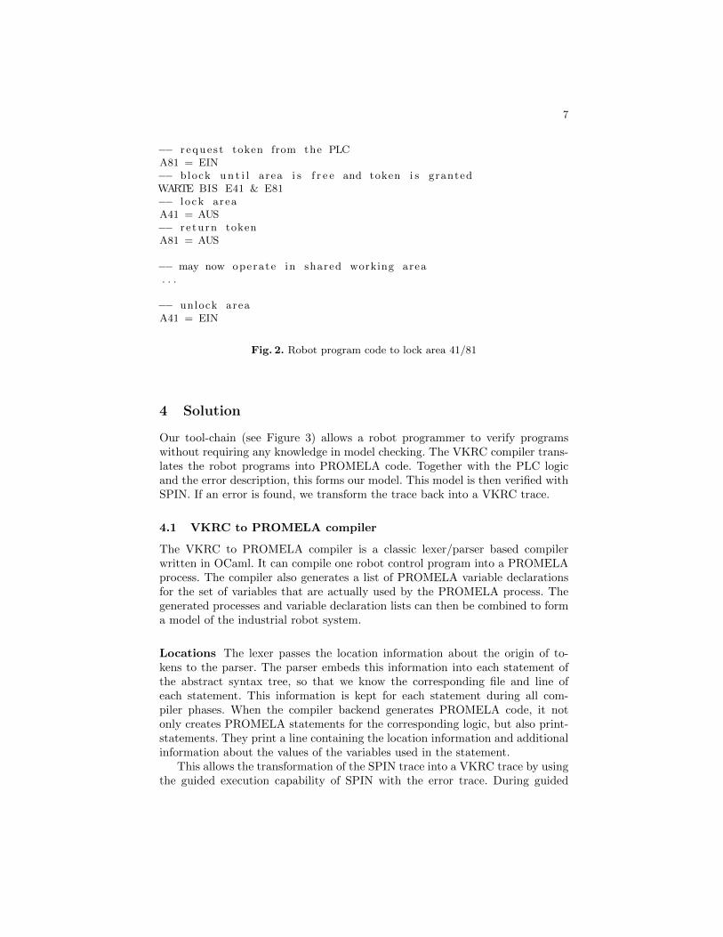
If a robot wants to lock a certain area, it first requests the correspondingtoken from the PLC. The PLC will hand out this token only to one robot at atime and will withdraw it only if the robot gives it back. A robot that has a tokenis allowed to take the actual lock – if it is not already taken. After obtaining theactual lock, the robot will give back the token. When it has left the correspondingarea, the robot must unlock the area (see figure 1). The corresponding programcode of the robot can be seen in figure 2.
Robot 1 PLC
Request Token
Robot 2
Lock Area
Release Token
Unlock Area
Grant Token
Fig. 1. Robot 1 successfully locks a shared working area
7
−− r eque s t token from the PLCA81 = EIN−− block u n t i l area i s f r e e and token i s grantedWARTE BIS E41 & E81−− l o ck areaA41 = AUS−− re turn tokenA81 = AUS
−− may now operate in shared working area. . .
−− unlock areaA41 = EIN
Fig. 2. Robot program code to lock area 41/81
4 Solution
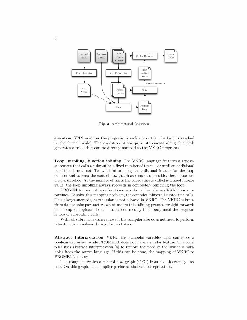
Our tool-chain (see Figure 3) allows a robot programmer to verify programswithout requiring any knowledge in model checking. The VKRC compiler trans-lates the robot programs into PROMELA code. Together with the PLC logicand the error description, this forms our model. This model is then verified withSPIN. If an error is found, we transform the trace back into a VKRC trace.
4.1 VKRC to PROMELA compiler
The VKRC to PROMELA compiler is a classic lexer/parser based compilerwritten in OCaml. It can compile one robot control program into a PROMELAprocess. The compiler also generates a list of PROMELA variable declarationsfor the set of variables that are actually used by the PROMELA process. Thegenerated processes and variable declaration lists can then be combined to forma model of the industrial robot system.
Locations The lexer passes the location information about the origin of to-kens to the parser. The parser embeds this information into each statement ofthe abstract syntax tree, so that we know the corresponding file and line ofeach statement. This information is kept for each statement during all com-piler phases. When the compiler backend generates PROMELA code, it notonly creates PROMELA statements for the corresponding logic, but also print-statements. They print a line containing the location information and additionalinformation about the values of the variables used in the statement.
This allows the transformation of the SPIN trace into a VKRC trace by usingthe guided execution capability of SPIN with the error trace. During guided
8
Robot Control Program
Robot Process
Spin
Robot Control Program
Robot Process
VKRC Compiler
Promela Trace
Spin
Inter-mediate Trace
CollisionClaims
Replay RendererSystem Trace
PLCProcess
Interlock Matrix
PLC Generator
Robot Process
Guided Execution
Robot Control Program
Fig. 3. Architectural Overview
execution, SPIN executes the program in such a way that the fault is reachedin the formal model. The execution of the print statements along this pathgenerates a trace that can be directly mapped to the VKRC programs.
Loop unrolling, function inlining The VKRC language features a repeat-statement that calls a subroutine a fixed number of times – or until an additionalcondition is not met. To avoid introducing an additional integer for the loopcounter and to keep the control flow graph as simple as possible, these loops arealways unrolled. As the number of times the subroutine is called is a fixed integervalue, the loop unrolling always succeeds in completely removing the loop.
PROMELA does not have functions or subroutines whereas VKRC has sub-routines. To solve this mapping problem, the compiler inlines all subroutine calls.This always succeeds, as recursion is not allowed in VKRC. The VKRC subrou-tines do not take parameters which makes this inlining process straight forward:The compiler replaces the calls to subroutines by their body until the programis free of subroutine calls.
With all subroutine calls removed, the compiler also does not need to performinter-function analysis during the next step.
Abstract Interpretation VKRC has symbolic variables that can store aboolean expression while PROMELA does not have a similar feature. The com-piler uses abstract interpretation [6] to remove the need of the symbolic vari-ables from the source language. If this can be done, the mapping of VKRC toPROMELA is easy.
The compiler creates a control flow graph (CFG) from the abstract syntaxtree. On this graph, the compiler performs abstract interpretation.
9
The compiler can perform constant evaluation, copy propagation and deadcode elimination: The goal is to remove the assignments to the symbolic vari-ables. First the compiler performs constant evaluation, to simplify the CFG.With this simplification in place, the copy propagation optimization can deter-mine the value of the symbolic variables in the statements they are used in. Afterthe copy propagation, the symbolic variables occuring in right-hand side valuesare replaced by their value. This step removes the usage of the symbolic variablesin right-hand side values. This in turn makes the assignments to the symbolicvariables unnecessary. The dead code analysis can now determine which assign-ments are unnecessary and remove them. After this step, no symbolic variablesshould appear on left-hand side values anymore either.
The abstract interpretation allows us to get rid of the symbolic variables, sothat no PROMELA code needs to get generated for them. There can be VKRCprograms for which this method does not work. The method worked for all robotcontrol programs we analyzed. If this method does not succeed, this could wellbe a programming error.
The compiler can be told to only perform the optimizations on the symbolicvariables instead of all variables. This can lead to minor differences in the timerequired to verify the model as can be seen in section 5.
Movement commands The robot control programs have movement com-mands. These commands will make the robotic arm move to the given posi-tion. The positions are given as integer numbers in the robot control program;a lookup-table exists where the actual movement coordinates are stored. Weknow from the CAD program the industrial robot system is planned in, whichcombinations of robots in which positions can lead to collisions.
The VKRC compiler translates the movement commands to assignments toa global position variable. The target points of the movements are enumeratedalready, so we use these numbers as right-hand side value of the assignment.
During movement, the robot continuously checks the kill-switch variable.This symbolic variable is evaluated and if returns false, will make the robotperform an emergency stop. To map this behavior, the compiler inserts an assertstatement on the value of the kill-switch variable at the position of the movementcommand. This way the model checker will find a violation of this property.
4.2 PLC generator
For the functioning of the locking mechanism, a model of the PLC is required.We have written a code generator that creates this model based on the interlockconfiguration.
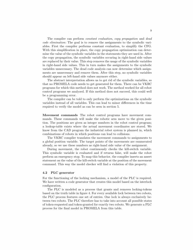
The PLC is modeled as a process that grants and removes locking-tokensbased on the truth table in figure 4. For every available lock between two robots,the PLC process features one set of entries. One lock is always exclusively be-tween two robots. The PLC therefore has to take into account all possible statesof token-requested and token-granted for exactly two robots. We generate a PLCprocess for the final model in PROMELA from this table.
10
The PLC process consists of an event loop and decides non-deterministicallywhich token to grant or withdraw; the two robots n and m can request theirtokens Tn and Tm by sending requests Rn and Rm. For every lock in the system,we generate 8 lines for the PLC process: The table in figure 4 has 17 rows;the row with both robots requesting the locking token has a non-deterministicresult and for this reason appears twice. For the error-lines, where both robotshave been granted the locking token, no code needs to be generated as they areunreachable. The lines for which the PLC process does not need to take anyaction, can also be omitted.
Rn Rm Tn Tm T′n T′
m
0 0 0 0 - -0 0 0 1 - 0 remove token from m0 0 1 0 0 - remove token from n0 0 1 1 error the token was granted to both robots0 1 0 0 0 1 grant token to m0 1 0 1 - -0 1 1 0 0 10 1 1 1 error the token was granted to both robots1 0 0 0 1 - grant token to n1 0 0 1 1 0 grant token to n, remove from m1 0 1 0 - -1 0 1 1 error the token was granted to both robots1 1 0 0 1 - grant token to n1 1 0 0 - 1 grant token to m1 1 0 1 - -1 1 1 0 - -1 1 1 1 error the token was granted to both robots
Fig. 4. Truth table of how the PLC grants and removes tokens T based on requests R
The actual locking bits are exchanged directly between the robots. A robotis only allowed to claim an area if it owns the locking token and the area is notalready locked. The locking token is not required to release an area.
The robots can not directly communicate with each other, but all commu-nication is handled via the PLC. In the original system, the PLC performs amapping from the corresponding output variables of one robot to the inputvariables of the partner robot. We model this mapping by renaming the inputvariables to the output variables they are connected to.
4.3 Fault description
We are searching for three classes of faults:
– Deadlocks– Collisions– Kill-switch violations
11
Deadlocks are searched for by SPIN automatically. We only need to mark thePLC process with its event loop as not needing to terminate.
Collisions are found via the movement commands. We translate a movementcommand to an assignment of the unique movement point number to the positionvariable of the corresponding robot. The contents of this variable designate themovement coordinate that the robot is on its way to or has already reached.From the 3D model of the industrial robot system, we know which movementcombinations of which robots can cause collisions. We use this information toformulate a never claim: No combination of locations of two robots must occurthat would lead to a potential collision.
The user has to supply a matrix of possible collisions based on the movementpoints of the robot programs. From this matrix we generate claims in LTL; forevery possible collision between two robots – robot n at position i and robot mat position k – we add the claim:
�¬((positionn = i) ∧ (positionm = k))
Kill-switch violations are directly generated by the compiler as assertionsin the PROMELA process. While in movement the robot continuously checksthe FB SPS variable for its contents. If this is false, the robot will trigger anemergency stop. While in normal operation, this kind of emergency situationmust not occur; hence, it is considered an error in the model.
During translation the compiler determines the value of the FB SPS variableat each movement command. A movement command is then translated to theassignment to the position and a preceding PROMELA-assert statement. Thisassertion guarantees the expression in the kill-switch variable to be true duringmovement.
4.4 Putting the model together
To create a model for the entire industrial robot system, we combine the gen-erated files: We create a main PROMELA file that first includes the variabledeclaration files of all robots. It then includes the files of the robot processesand of the PLC process. The verification engineer then has to add a never claimfor the potential collision combinations. Finally we write a main process thatinitializes certain variables and then starts all robot processes and the PLCprocess.
As of now, we have several devices that are missing from our model, e. g.welding devices. To allow the robot program to work as intended, we manuallyset the variables that represent the feedback from those devices to their desiredvalue. This means these events always succeed and the behavior of the systemwith these events failing is not taken into account.
12
4.5 Replay trace
If the model checker finds a counter-example, it generates a trace leading to thiserror. This trace can be replayed in guided execution, executing the PROMELAprogram in such a way, that it leads to the found violation.
When executed in this way, the model checker will also execute the printf
statements that were inserted by the compiler. The back-end of the compilergenerates an accompanying printf statement for every statement generated.For a VKRC assignment, a PROMELA assignment is generated which is placedtogether with a printf statement inside an atomic block. This block then out-puts the original location of the VKRC statement and the values of the variablesused in the original statement.
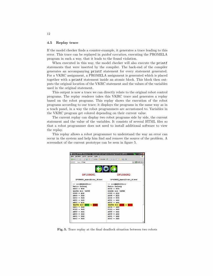
This output is now a trace we can directly relate to the original robot controlprograms. The replay renderer takes this VKRC trace and generates a replaybased on the robot programs. This replay shows the execution of the robotprograms according to our trace; it displays the programs in the same way as ina teach panel, in a way the robot programmers are accustomed to. Variables inthe VKRC program get colored depending on their current value.
The current replay can display two robot programs side by side, the currentstatement and the value of the variables. It consists of several HTML files sothat a robot programmer does not need to install additional software to viewthe replay.
This replay allows a robot programmer to understand the way an error canoccur in the system and help him find and remove the source of the problem. Ascreenshot of the current prototype can be seen in figure 5.
Fig. 5. Trace replay at the final deadlock situation between two robots
13
5 Evaluation
We conducted verification runs on a training station and on several recent car-body stations. The training station has 2 robots, while the car-body stationshave 9.
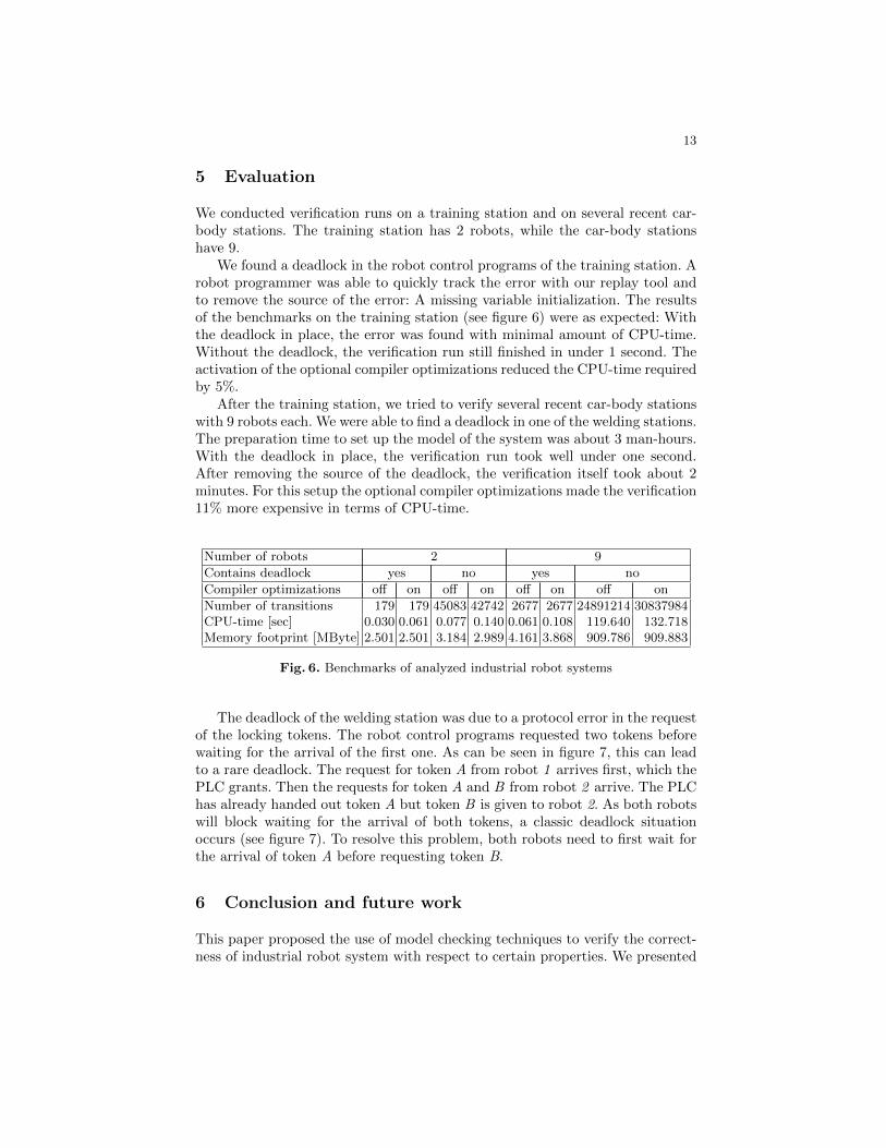
We found a deadlock in the robot control programs of the training station. Arobot programmer was able to quickly track the error with our replay tool andto remove the source of the error: A missing variable initialization. The resultsof the benchmarks on the training station (see figure 6) were as expected: Withthe deadlock in place, the error was found with minimal amount of CPU-time.Without the deadlock, the verification run still finished in under 1 second. Theactivation of the optional compiler optimizations reduced the CPU-time requiredby 5%.
After the training station, we tried to verify several recent car-body stationswith 9 robots each. We were able to find a deadlock in one of the welding stations.The preparation time to set up the model of the system was about 3 man-hours.With the deadlock in place, the verification run took well under one second.After removing the source of the deadlock, the verification itself took about 2minutes. For this setup the optional compiler optimizations made the verification11% more expensive in terms of CPU-time.
Number of robots 2 9
Contains deadlock yes no yes no
Compiler optimizations off on off on off on off on
Number of transitions 179 179 45083 42742 2677 2677 24891214 30837984CPU-time [sec] 0.030 0.061 0.077 0.140 0.061 0.108 119.640 132.718Memory footprint [MByte] 2.501 2.501 3.184 2.989 4.161 3.868 909.786 909.883
Fig. 6. Benchmarks of analyzed industrial robot systems
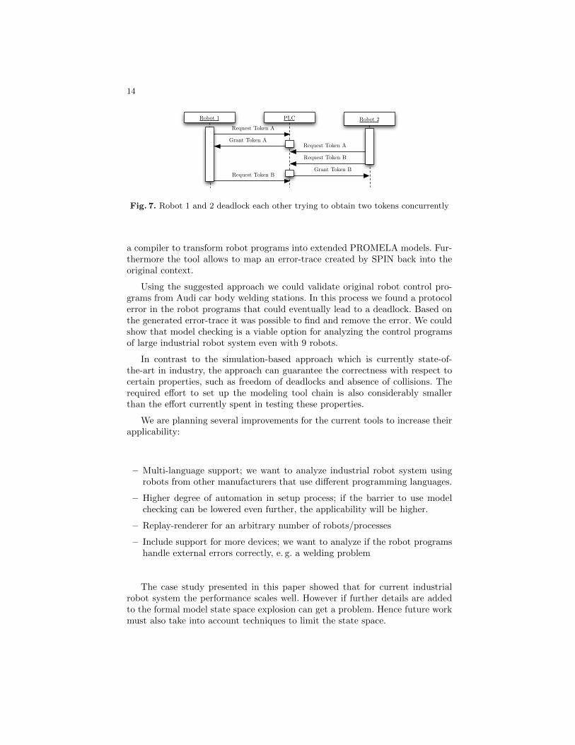
The deadlock of the welding station was due to a protocol error in the requestof the locking tokens. The robot control programs requested two tokens beforewaiting for the arrival of the first one. As can be seen in figure 7, this can leadto a rare deadlock. The request for token A from robot 1 arrives first, which thePLC grants. Then the requests for token A and B from robot 2 arrive. The PLChas already handed out token A but token B is given to robot 2. As both robotswill block waiting for the arrival of both tokens, a classic deadlock situationoccurs (see figure 7). To resolve this problem, both robots need to first wait forthe arrival of token A before requesting token B.
6 Conclusion and future work
This paper proposed the use of model checking techniques to verify the correct-ness of industrial robot system with respect to certain properties. We presented
14
PLC Robot 2Request Token A
Request Token A
Robot 1
Grant Token A
Request Token B
Request Token B
Grant Token B
Fig. 7. Robot 1 and 2 deadlock each other trying to obtain two tokens concurrently
a compiler to transform robot programs into extended PROMELA models. Fur-thermore the tool allows to map an error-trace created by SPIN back into theoriginal context.
Using the suggested approach we could validate original robot control pro-grams from Audi car body welding stations. In this process we found a protocolerror in the robot programs that could eventually lead to a deadlock. Based onthe generated error-trace it was possible to find and remove the error. We couldshow that model checking is a viable option for analyzing the control programsof large industrial robot system even with 9 robots.
In contrast to the simulation-based approach which is currently state-of-the-art in industry, the approach can guarantee the correctness with respect tocertain properties, such as freedom of deadlocks and absence of collisions. Therequired effort to set up the modeling tool chain is also considerably smallerthan the effort currently spent in testing these properties.
We are planning several improvements for the current tools to increase theirapplicability:
– Multi-language support; we want to analyze industrial robot system usingrobots from other manufacturers that use different programming languages.
– Higher degree of automation in setup process; if the barrier to use modelchecking can be lowered even further, the applicability will be higher.
– Replay-renderer for an arbitrary number of robots/processes
– Include support for more devices; we want to analyze if the robot programshandle external errors correctly, e. g. a welding problem
The case study presented in this paper showed that for current industrialrobot system the performance scales well. However if further details are addedto the formal model state space explosion can get a problem. Hence future workmust also take into account techniques to limit the state space.
15
References
1. Nanette Bauer, Sebastian Engell, Ralf Huuck, Ben Lukoschus, and Olaf Stursberg,Stursberg: Verification of PLC Programs given as Sequential Function Charts, In:Integration of Software Specification Techniques for Applications in Eng., Springer,LNCS, 2004, pp. 517–540.
2. Dirk Beyer, Thomas Henzinger, Ranjit Jhala, and Rupak Majumdar, The softwaremodel checker BLAST, International Journal on Software Tools for TechnologyTransfer (STTT) 9 (2007), 505–525, 10.1007/s10009-007-0044-z.
3. Sebastien Bornot, Ralf Huuck, Yassine Lakhnech, and Ben Lukoschus, Utilizingstatic analysis for programmable logic controllers, ADPM 2000: The 4th Interna-tional Conference on Automation of Mixed Processes: Hybrid Dynamic Systems,2000, pp. 183–187.
4. G. Canet, S. Couffin, J. j. Lesage, A. Petit, and Ph. Schnoebelen, Towards the auto-matic verification of PLC programs written in Instruction List, IEEE InternationalConference on Systems, Man and Cybernetics, 2000, pp. 2449–2454.
5. James C. Corbett, Matthew B. Dwyer, John Hatcliff, Shawn Laubach, Corina S.Pasareanu, and Hongjun Zheng, Bandera: Extracting Finite-state Models from JavaSource Code, Proceedings of the 22nd international conference on Software engi-neering, ACM Press, 2000, pp. 439–448.
6. Patrick Cousot and Radhia Cousot, Abstract interpretation: a unified lattice modelfor static analysis of programs by construction or approximation of fixpoints, Pro-ceedings of the 4th ACM SIGACT-SIGPLAN symposium on Principles of pro-gramming languages (New York, NY, USA), POPL ’77, ACM, 1977, pp. 238–252.
7. Patrick Cousot and Radhia Cousot, Verification of embedded software: Problemsand perspectives, Proceedings of the 1st International Workshop on EmbeddedSoftware (EMSOFT), USA. LNCS 2211, Springer-Verlag, 2001, pp. 97–113.
8. Pedro de la Camara, Marıa del Mar Gallardo, and Pedro Merino, Model extractionfor ARINC 653 based avionics software, Proceedings of the 14th international SPINconference on Model checking software (Berlin, Heidelberg), Springer-Verlag, 2007,pp. 243–262.
9. Yifei Dong and C. R. Ramakrishnan, An optimizing compiler for efficient modelchecking, Proceedings of the IFIP TC6 WG6.1 Joint International Conference onFormal Description Techniques for Distributed Systems and Communication Pro-tocols (FORTE XII) and Protocol Specification, Testing and Verification (PSTVXIX) (Deventer, The Netherlands, The Netherlands), FORTE XII / PSTV XIX’99, Kluwer, B.V., 1999, pp. 241–256.
10. Lucio Mauro Duarte, Jeff Kramer, and Sebastian Uchitel, Towards faithful modelextraction based on contexts, Proceedings of the Theory and practice of software,11th international conference on Fundamental approaches to software engineering(Berlin, Heidelberg), FASE’08/ETAPS’08, Springer-Verlag, 2008, pp. 101–115.
11. Klaus Havelund, Java PathFinder, A Translator from Java to Promela, Proceed-ings of the 5th and 6th International SPIN Workshops on Theoretical and PracticalAspects of SPIN Model Checking (London, UK), Springer-Verlag, 1999, pp. 152–.
12. Gerard J. Holzmann, The Model Checker SPIN, IEEE Transactions on SoftwareEngineering 23 (1997), 279–295.
13. Gerard J. Holzmann and Margaret H. Smith, An automated verification methodfor distributed systems software based on model extraction, IEEE Transactions onSoftware Engineering 28 (2002), 364–377.
16
14. Mauro Mazzolini, Alessandro Brusaferri, and Emanuele Carpanzano, Model-checking based verification approach for advanced industrial automation solutions,Emerging Technologies and Factory Automation (ETFA), 2010, pp. 1–8.
15. Olivera Pavlovic, Ralf Pinger, and Mail Kollmann, Automated formal verificationof PLC programs written in IL, Conference on Automated Deduction (CADE),2007, pp. 152–163.
16. Bastian Schlich, Jorg Brauer, Jorg Wernerus, and Stefan Kowalewski, Direct modelchecking of PLC programs in IL, 2nd IFAC Workshop on Dependable Control ofDiscrete Systems (DCDS) (Bari, Italy), 2009.
17. Helmut Seidl and Vesal Vojdani, Region analysis for race detection, Proceedingsof the 16th International Symposium on Static Analysis (Berlin, Heidelberg), SAS’09, Springer-Verlag, 2009, pp. 171–187.
18. Hai Wan, Gang Chen, Xiaoyu Song, and Ming Gu, Formalization and Verificationof PLC Timers in Coq, Proceedings of the 2009 33rd Annual IEEE InternationalComputer Software and Applications Conference - Volume 01 (Washington, DC,USA), IEEE Computer Society, 2009, pp. 315–323.
19. Mohammed Bani Younis and Georg Frey, Formalization of existing PLC programs:A survey, Proceedings of Computing Engineering in Systems Applications (CESA)(Lille, France), July 2003.