Embed Size (px)
DESCRIPTION
magazin
Citation preview
£6.99
SP
EC
IAL
ISS
UE
201
4 P
RIN
TED
IN T
HE
UK
MO
DE
L G
RO
UP
Build some of the 20th Century warships that changed history
TemerityH.M.S.H.M.S.
WW2 ROYAL NAVY DESTROYERWW2 ROYAL NAVY DESTROYER
WW2 ROYAL NAVY DESTROYER WORTH £17.50EXCLUSIVE FREE PLAN! SPECIAL ISSUE
U.S.S. Bodega Bay
LCT6
Stunning stand-off scale model escort carrier
Glynn Guests’ semi-scale working model based on a WW2 tank landing craft w
ww
.mod
elboa
ts.c
o.uk
H.M.T. Sir Lancelot
Avispa
Giuseppe Garibaldi
1942 minesweeper
The history behind WW1 coastal motor boats
Take a look inside H.M.S. Belfast
Royal Navy postcards
Torpedo boat destroyer
Italy’s fl agship aircraft carrier
and many more...
Our guide to the best model boat warships
WARSHIPSWAR POWER!
MODEL BOATMODEL BOAT
SEMI-SCALE PLAN!FREE
PLUS
132PAGE
SPECIAL ISSUE

Model Boats Warships 125
Model Boats Warships 3
Welcome
Model Boats Warships is published once a year by MyTimeMedia Ltd, Hadlow House, 9 High Street, Green Street Green, Orpington, Kent BR6 6BG
© MyTimeMedia Ltd. 2014. All rights reserved ISBN 9781907063688. The Publisher’s written consent must be obtained before any part of this publication may be reproduced in any form whatsoever, including photocopiers, and information retrieval systems. All reasonable care is taken in the preparation of the magazine contents, but the publishers cannot be held legally responsible for errors in the contents of this magazine or for any loss however arising from such errors, including loss resulting from negligence of our staff. Reliance placed upon the contents of this magazine is at reader’s own risk.
Welcome to this special issue from the publishers ofEDITORIALGlynn GuestColin BishopPaul Freshney PRODUCTIONDesign Manager: Siobhan Nolan
DESIGN & RETOUCHINGSteve StonerNik Harber
ADVERTISING Ben [email protected]: 01689 869851
MANAGEMENTPublisher: Julie Miller
Chief Executive: Owen Davies
Chairman: Peter Harkness
BACK ISSUESTel: 0844 848 8822From outside UK +44 (0) 133 261 2894 [email protected] www.myhobbystore.co.uk
Any country that has an economy which depends on seaborne trade inevitably
recognises the need for a Navy to protect this vital link. Once you have a Navy
it can also be used to threaten, if not deny the use of the sea by any potential
enemies. Even countries with modest coastlines will feel the need to have some sort of
littoral protection. So it is not diffi cult to see that warships have, from the earliest days
of oar and sail power to the modern nuclear powered behemoths, featured prominently
in human history. This makes them fascinating subjects for many people so their
popularity as a subject for working models ought to be a surprise to no one.
However, models of warships have always had something of a reputation of being
“diffi cult” compared with something like a model based on a tug or lifeboat design.
It is true that having a narrower beam can make a warship model less stable than a
beamier model but, it does not mean that they are going to be unstable. Careful design
and construction, usually by keeping the weight of items above the deck as light as
possible and any internal ballast as low as possible, can avoid such problems. The advent
of economical and reliable Radio Control equipment, along with suitable electric power,
has also gone a long way in making the warship modellers life much easier.
It is possible to buy a suitable warship model in kit form, indeed if cost is no
objection you can now buy highly detailed ready to sail model warships. But many
modellers prefer to build their own which means they can say “it’s all my own work”.
There is an intermediate route of buying a commercial ready made hull, usually in Glass
Reinforced Plastic, and then building the decks and superstructure upon it. However
the model is built you still have to fi rst decide on which vessel to base the model on and
then just how much detail to add.
This publication includes a Free plan worth £17.50 for a destroyer model that ought
to be straightforward to build especially if you use the associated woodpack kit. It was
designed to represent the many destroyers built for the Royal Navy during World War
Two rather than be based on a specifi c vessel. It can be easily altered to match several
different classes of destroyers. It may fall into the category of semi or stand-off scale
but dashing across the water it looks the part of warship moving purposely into action.
Which is just what any working model ought to do!
For more special features, and great subscriber offers go to www.modelboats.co.uk
Glynn Guest 2014
4 www.modelboats.co.uk
MODEL BOATS WARSHIPS
CONTENTS
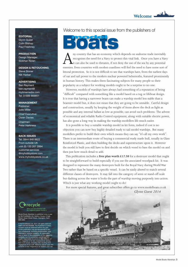
HMS Daring.. . . . . . . . . . . . . . . . . . . . . 30TONY DALTON describes his semi-scale model of the Royal Navy’s new toy
Historical postcards.. . .24Colin Bishop takes a look at how the Navy changed between the wars using a unique collection of postcards.
Coastal boats.. . . . . . . . . . . . . . . . . 18Coastal motor boats performed a vital role in attackingGerman naval bases and shipping. IVOR WARNE takes a look at the survivors
Dazzle ships.. . . . . . . . . . . . . . . . . . . . 12ANTHONY ADDAMS explores ship subterfuge
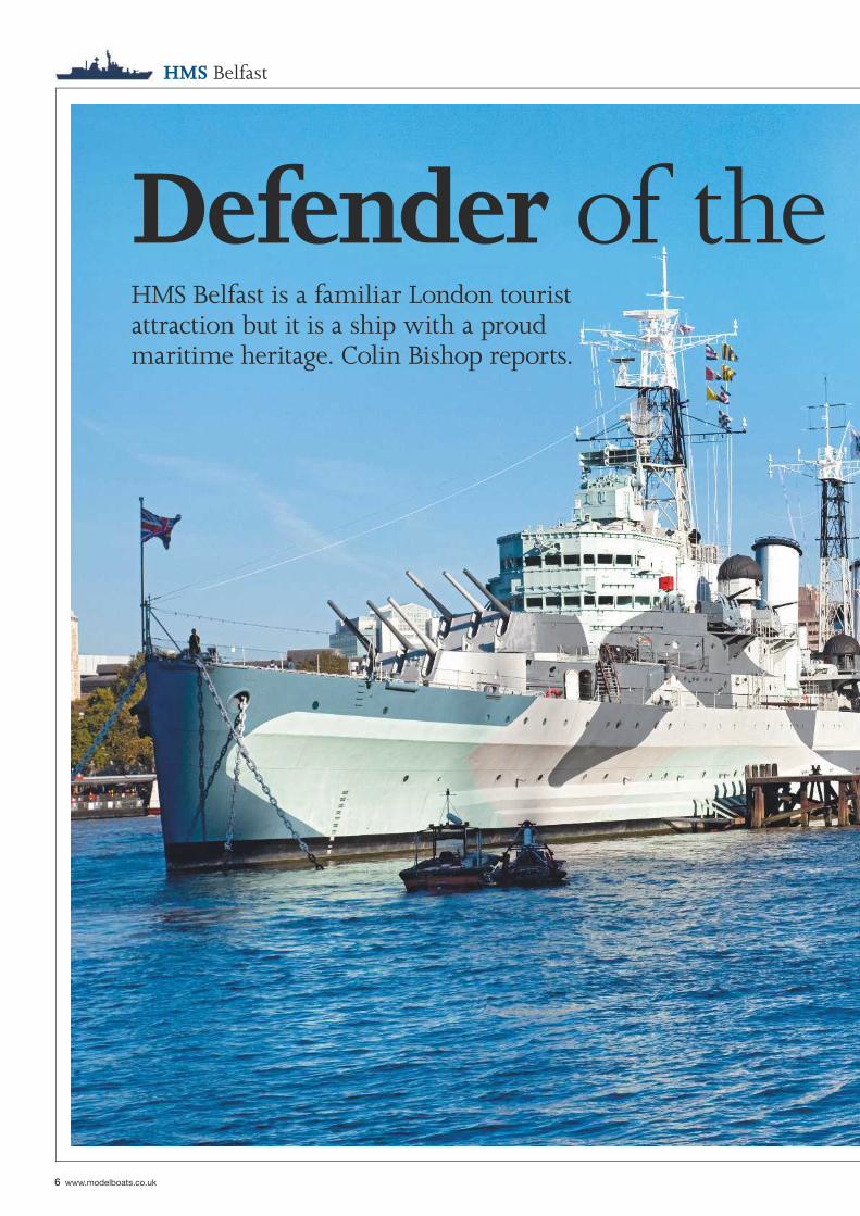
HMS Belfast . . . . . . . . . . . . . . . . . . . . . . .6HMS Belfast is a familiar London tourist attraction but it is a ship with a proud maritime heritage. Colin Bishop reports.
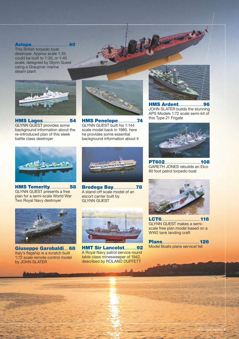
Model Boats Warships 5
LCT6... . . . . . . . . . . . . . . . . . . . . . . . . . . . . . . . 116GLYNN GUEST makes a semi-scale free plan model based on a WW2 tank landing craft
PT602... . . . . . . . . . . . . . . . . . . . . . . . . . . . . .108GARETH JONES rebuilds an Elco 80 foot patrol torpedo boat
HMS Ardent.. . . . . . . . . . . . . . . . . . . . .96JOHN SLATER builds the stunning APS Models 1:72 scale semi-kit of this Type 21 Frigate
Brodega Bay.. . . . . . . . . . . . . . . . . . . 78A stand-off scale model of an escort carrier built by GLYNN GUEST
HMS Penelope... . . . . . . . . . . . . . . 74GLYNN GUEST built his 1:144 scale model back in 1980. here he provides some essential background information about it
Giuseppe Garobaldi.. . . 68Italy’s fl agship is a scratch built 1:72 scale remote control model by JOHN SLATER
HMS Temerity.. . . . . . . . . . . . . . . . .58GLYNN GUEST presents a free plan for a semi-scale World War Two Royal Navy destroyer
HMT Sir Lancelot.. . . . . . . . . .92A Royal Navy patrol service round table class minesweeper of 1942, described by ROLAND DUFFETT
Avispa... . . . . . . . . . . . . . . . . . . . . . . . . . . . . . . 40This British torpedo boat destroyer, Approx scale 1:35, could be built to 1:30, or 1:40 scale, designed by Glynn Guest using a Graupner marine steam plant
HMS Lagos... . . . . . . . . . . . . . . . . . . . . .54GLYNN GUEST provides some background information about the re-introduced plan of this sleek battle class destroyer
Plans.. . . . . . . . . . . . . . . . . . . . . . . . . . . . . . . . 126Model Boats plans servicel list
6 www.modelboats.co.uk
HMS Belfast
Defender of the HMS Belfast is a familiar London tourist attraction but it is a ship with a proud maritime heritage. Colin Bishop reports.
Model Boats Warships 7
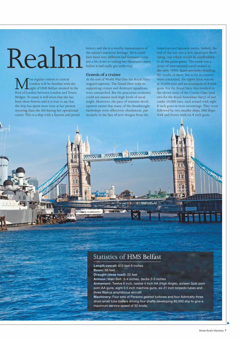
Most regular visitors to central London will be familiar with the sight of HMS Belfast moored in the
Pool of London between London and Tower Bridges. To many it will seem that she has been there forever and it is true to say that the ship has spent more time at her present mooring than she did during her operational career. This is a ship with a famous and proud
Realmhistory and she is a worthy representative of the nation’s maritime heritage. Yet it could have been very different had Germany come just a bit closer to ending her illustrious career before it had really got underway.
Genesis of a cruiserAt the end of World War One the Royal Navy reigned supreme. The Grand Fleet with its supporting cruiser and destroyer squadrons were unmatched. But the peacetime economy could not sustain such high levels of naval might. Moreover, the pace of wartime devel-opment meant that many of the dreadnought battleships were effectively obsolescent, par-ticularly in the face of new designs from the
American and Japanese navies. Indeed, the end of the war saw a new naval race devel-oping, one which would be unaffordable to all the participants. The result was a series of international naval treaties in the early 1920s. Space precludes detailing the results of these, but as far as cruisers were concerned, the upper limit was set at 10,000 tons and an armament of 8 inch guns. For the Royal Navy this resulted in the eleven units of the County Class (and two for the Royal Australian Navy) of just under 10,000 tons, each armed with eight 8 inch guns in twin mountings. They were followed by two smaller ships, HM Ships York and Exeter with six 8 inch guns.
Statistics of HMS BelfastLength overall: 613 feet 6 inchesBeam: 66 feetDraught (deep load): 22 feetArmour: Main Belt: 3-4 inches, decks 2-3 inchesArmament: Twelve 6 inch, twelve 4 inch HA (High Angle), sixteen 2pdr pom pom AA guns, eight 0.5 inch machine guns, six 21 inch torpedo tubes and three Walrus amphibious aircraftMachinery: Four sets of Parsons geared turbines and four Admiralty three drum small tube boilers driving four shafts developing 80,000 shp to give a maximum service speed of 32 knots.
8 www.modelboats.co.uk
HMS Belfast
The ‘Counties’ were expensive ships and did not meet the RN need for numbers to protect the sea lanes of the British Empire. The end of WW1 saw the introduction into service of the C and D Class cruisers which carried a uniform armament of 6 inch guns in single mountings. Although state of the art in their day, they were becoming out-dated in the 1930s, although many acquitted themselves well in WW2, especially those converted to anti-aircraft ships. The response of the Admiralty was to build the Leander (5 ships) and Amphion (3 ships) Classes of around 8,000 tons, armed with eight 6 inch guns in twin mountings. They were followed by smaller vessels of the Arethusa (4 ships) Class intended mainly for commerce protec-tion with just six 6 inch guns.
Meanwhile, international naval thinking was moving away from 8 inch gun cruisers, the opinion being that a vessel mounting a larger number of quick fi ring 6 inch guns would overwhelm the heavier gunned ship, provided that the more lightly armed cruiser could get close enough. Despite the much heavier 8 inch shell, 250lbs against the 112lb 6 inch, nominal rates of fi re indicated that the light cruiser could deliver a much greater weight of fi re in a given period. In practice, when using aimed fi re, the disparity
was much less than claimed, but both the American and Japanese navies embraced the concept with their Brooklyn and Mogami Classes mounting no less than fi fteen 6 inch guns. The Royal Navy’s response was to develop the somewhat smaller Southampton, or Town, Class from the Leander design, armed with twelve 6 inch guns in four triple turrets. These were well balanced ships with a handsome profi le and proved to be excel-lent designs under wartime conditions where they were used extensively in the Mediterra-nean. The eight ships of the fi rst two batches were generally similar but with the last two, Edinburgh and Belfast, the Admiralty wanted an enlarged, up gunned version with four quadruple turrets to match foreign rivals. The secondary armament was also to be upgraded from eight to twelve 4 inch. However, trials with a prototype version of the quadruple turret showed that there were problems with shells from adjacent guns interfering and col-liding with each other. Rectifying this with wider turrets to increase the spread between the guns had implications for the arcs over which the guns would bear. Remedying this meant lengthening the ship and increasing the armour weight and so on. In the end it was decided to stick with the same twelve gun confi guration of the earlier ships, but to
retain the intended improvements in armour and secondary guns. It was also decided to move the 4 inch gun magazine forward of the machinery spaces which necessitated a 110 foot trolley system to move ammunition to the 4 inch guns along the upper deck from the hoists on the fl ight deck – this was nicknamed the ‘Scenic Railway’. The reason for this change is not known although it has been suggested that it was to minimise the length of the propeller shafts. It did however have a major effect on the appearance of the ship with the fore funnel now stepped well aft of the bridge and the after funnel behind the mainmast. Improvements to the turret, shell handling and magazine arrangements necessitated mounting the after turrets one deck higher than in the previous vessels. The overall effect was to give Edinburgh and Bel-fast a rather unbalanced and heavier appear-ance compared with their more elegant half sisters and the changes made them the only 6 inch cruisers built up to the 10,000 ton treaty limit (which they actually exceeded) and they were able to withstand 8 inch gunfi re.
Service historyOn completion, H.M.S Belfast was commis-sioned into the Fleet on 5th August 1939 as war clouds gathered over Europe. Following
“ At the end of WW1 the Royal Navy reigned supreme. The Grand Fleet with its supporting cruiser & destroyer squadrons were unmatched ”
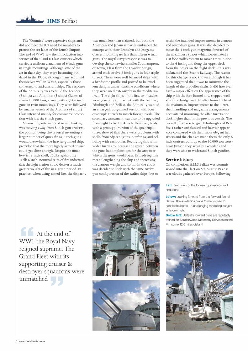
below: Looking forward from the forward funnel. Below: The amidships crane formerly used to handle the boats – a challenging modelling subject in its own right.
Left: Front view of the forward gunnery control and radar.
Below left: Belfast’s forward guns are reputedly trained on Scratchwood Motorway Services on the M1, some 12.5 miles distant!
Model Boats Warships 9
the outbreak of war, the ship was assigned to the 18th cruiser squadron operating out of Scapa Flow as part of the blockade of Germany. On 9th October she scored her fi rst success in capturing the German liner Cap Norte, NW of the Faroe Islands. However, this was almost to be the sum total of her career. In November, while serving with the 2nd Cruiser Squadron operating out of Rosyth, she set off a magnetic mine while proceeding to sea on exercises. The effect was devastating. The middle of the vessel was pushed up by over four feet and her back was broken. The whiplash effect shattered equipment throughout the ship, particularly iron castings for mounting heavy items like the turbines and she was totally immobilised. Temporary patching up enabled the ship to reach Devonport where the decision was almost made to scrap her. Due to other priorities, the extensive repairs required were protracted and not completed until November 1942. Repairs to the hull included fi tting an anti-torpedo bulge with the armour belt refi tted outboard of it. The opportunity was also taken to update the ship with the latest radar and other electronics. When she re-entered service, Belfast was indeed a formidable ship.
Belfast spent most of 1943 in Arctic waters escorting or covering Russian convoys. These
arduous duties culminated in what was per-haps the high point of her career – the Battle of North Cape on 26th December in which the Home Fleet consisting of the battleship Duke of York, four cruisers and destroyers in-tercepted and sank the German battlecruiser Scharnhorst which was bent upon attacking convoy JW 55B near Bear Island off the North Cape of Norway. Belfast, together with the cruisers Sheffi eld and Norfolk, were the fi rst to sight Scharnhorst and bring her to action, Belfast scoring hits with her fourth salvo un-der radar control. A running battle developed which brought the battlecruiser within range of the Duke of York which rapidly scored damaging hits including one in a boiler room which reduced her speed, opening the way for a successful torpedo attack by the de-stroyers which left the crippled giant on fi re and dead in the water. Belfast and the cruiser Jamaica were ordered in to administer the coup de grace and Scharnhorst sank with the loss of all but 36 of her 1,968 crew. During the action Belfast fi red 316 six inch shells, 77 four inch shells and three torpedoes.
At the end of March 1944, Belfast par-ticipated as part of the covering forces in Operation Tungsten, a Fleet Air Arm attack on the battleship Tirpitz in Altenfjord, Nor-way which put her out of action until July.
Belfast’s next major task was to act as fl agship of one of the D Day bombardment forces. Over the course of fi ve weeks she provided gunfi re support to the troops ashore. The ship then underwent a major refi t to prepare her for service against the Japanese during which two of the twin 4 inch gun mountings were removed to allow more close range anti air-craft weapons to be fi tted. Her aircraft were landed, the catapult removed and the hangers converted to accommodation. Her electronics were upgraded and the ship was modifi ed to improve habitability in the tropics. Following completion of her refi t in April 1945 and a short working up period in Malta, Belfast sailed for the Far East, but the Japanese had surrendered before her arrival. The ship then spent a hectic period dealing with the after-math of the war and evacuating prisoners of war from Japanese prison camps. Belfast was to remain in the Far East until October 1947 before paying off into reserve.
A year later following another refi t, Belfast was off to the Far East again where she par-ticipated in the fi nal stages of the well known incident involving HMS Amethyst. The years 1950 to 1952 saw Belfast engaged almost full time in the Korean War as part of the United Nations forces. Much of her time was taken up with bombardment duties in support of the
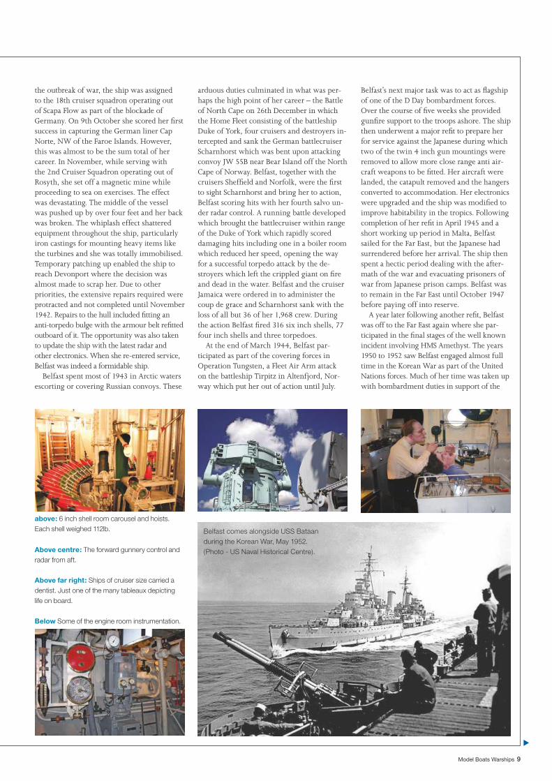
above: 6 inch shell room carousel and hoists. Each shell weighed 112lb.
Below Some of the engine room instrumentation.
Above centre: The forward gunnery control and radar from aft.
Above far right: Ships of cruiser size carried a dentist. Just one of the many tableaux depicting life on board.
Belfast comes alongside USS Bataan during the Korean War, May 1952. (Photo - US Naval Historical Centre).
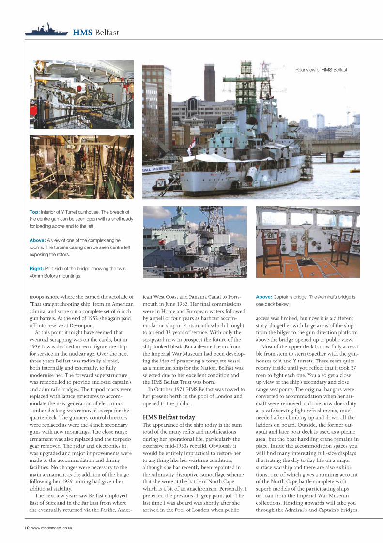
Top: Interior of Y Turret gunhouse. The breech of the centre gun can be seen open with a shell ready for loading above and to the left.
Right: Port side of the bridge showing the twin 40mm Bofors mountings.
Above: A view of one of the complex engine rooms. The turbine casing can be seen centre left, exposing the rotors.
Above: Captain’s bridge. The Admiral’s bridge is one deck below.
10 www.modelboats.co.uk
HMS Belfast
troops ashore where she earned the accolade of ‘That straight shooting ship’ from an American admiral and wore out a complete set of 6 inch gun barrels. At the end of 1952 she again paid off into reserve at Devonport.
At this point it might have seemed that eventual scrapping was on the cards, but in 1956 it was decided to reconfi gure the ship for service in the nuclear age. Over the next three years Belfast was radically altered, both internally and externally, to fully modernise her. The forward superstructure was remodelled to provide enclosed captain’s and admiral’s bridges. The tripod masts were replaced with lattice structures to accom-modate the new generation of electronics. Timber decking was removed except for the quarterdeck. The gunnery control directors were replaced as were the 4 inch secondary guns with new mountings. The close range armament was also replaced and the torpedo gear removed. The radar and electronics fi t was upgraded and major improvements were made to the accommodation and dining facilities. No changes were necessary to the main armament as the addition of the bulge following her 1939 mining had given her additional stability.
The next few years saw Belfast employed East of Suez and in the Far East from where she eventually returned via the Pacifi c, Amer-
ican West Coast and Panama Canal to Ports-mouth in June 1962. Her fi nal commissions were in Home and European waters followed by a spell of four years as harbour accom-modation ship in Portsmouth which brought to an end 32 years of service. With only the scrapyard now in prospect the future of the ship looked bleak. But a devoted team from the Imperial War Museum had been develop-ing the idea of preserving a complete vessel as a museum ship for the Nation. Belfast was selected due to her excellent condition and the HMS Belfast Trust was born.
In October 1971 HMS Belfast was towed to her present berth in the pool of London and opened to the public.
HMS Belfast todayThe appearance of the ship today is the sum total of the many refi ts and modifi cations during her operational life, particularly the extensive mid-1950s rebuild. Obviously it would be entirely impractical to restore her to anything like her wartime condition, although she has recently been repainted in the Admiralty disruptive camoufl age scheme that she wore at the battle of North Cape which is a bit of an anachronism. Personally, I preferred the previous all grey paint job. The last time I was aboard was shortly after she arrived in the Pool of London when public
access was limited, but now it is a different story altogether with large areas of the ship from the bilges to the gun direction platform above the bridge opened up to public view.
Most of the upper deck is now fully accessi-ble from stem to stern together with the gun-houses of A and Y turrets. These seem quite roomy inside until you refl ect that it took 27 men to fi ght each one. You also get a close up view of the ship’s secondary and close range weaponry. The original hangars were converted to accommodation when her air-craft were removed and one now does duty as a cafe serving light refreshments, much needed after climbing up and down all the ladders on board. Outside, the former cat-apult and later boat deck is used as a picnic area, but the boat handling crane remains in place. Inside the accommodation spaces you will fi nd many interesting full-size displays illustrating the day to day life on a major surface warship and there are also exhibi-tions, one of which gives a running account of the North Cape battle complete with superb models of the participating ships on loan from the Imperial War Museum collections. Heading upwards will take you through the Admiral’s and Captain’s bridges,
Rear view of HMS Belfast
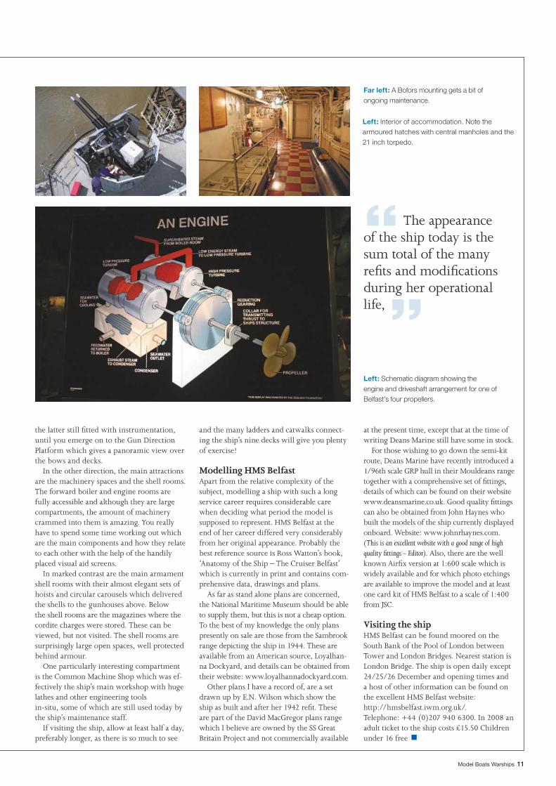
Far left: A Bofors mounting gets a bit of ongoing maintenance.
Left: Interior of accommodation. Note the armoured hatches with central manholes and the 21 inch torpedo.
Left: Schematic diagram showing the engine and driveshaft arrangement for one of Belfast’s four propellers.
Model Boats Warships 11
the latter still fi tted with instrumentation, until you emerge on to the Gun Direction Platform which gives a panoramic view over the bows and decks.
In the other direction, the main attractions are the machinery spaces and the shell rooms. The forward boiler and engine rooms are fully accessible and although they are large compartments, the amount of machinery crammed into them is amazing. You really have to spend some time working out which are the main components and how they relate to each other with the help of the handily placed visual aid screens.
In marked contrast are the main armament shell rooms with their almost elegant sets of hoists and circular carousels which delivered the shells to the gunhouses above. Below the shell rooms are the magazines where the cordite charges were stored. These can be viewed, but not visited. The shell rooms are surprisingly large open spaces, well protected behind armour.
One particularly interesting compartment is the Common Machine Shop which was ef-fectively the ship’s main workshop with huge lathes and other engineering tools in-situ, some of which are still used today by the ship’s maintenance staff.
If visiting the ship, allow at least half a day, preferably longer, as there is so much to see
and the many ladders and catwalks connect-ing the ship’s nine decks will give you plenty of exercise!
Modelling HMS BelfastApart from the relative complexity of the subject, modelling a ship with such a long service career requires considerable care when deciding what period the model is supposed to represent. HMS Belfast at the end of her career differed very considerably from her original appearance. Probably the best reference source is Ross Watton’s book, ‘Anatomy of the Ship – The Cruiser Belfast’ which is currently in print and contains com-prehensive data, drawings and plans.
As far as stand alone plans are concerned, the National Maritime Museum should be able to supply them, but this is not a cheap option. To the best of my knowledge the only plans presently on sale are those from the Sambrook range depicting the ship in 1944. These are available from an American source, Loyalhan-na Dockyard, and details can be obtained from their website: www.loyalhannadockyard.com.
Other plans I have a record of, are a set drawn up by E.N. Wilson which show the ship as built and after her 1942 refi t. These are part of the David MacGregor plans range which I believe are owned by the SS Great Britain Project and not commercially available
at the present time, except that at the time of writing Deans Marine still have some in stock.
For those wishing to go down the semi-kit route, Deans Marine have recently introduced a 1/96th scale GRP hull in their Mouldeans range together with a comprehensive set of fi ttings, details of which can be found on their website www.deansmarine.co.uk. Good quality fi ttings can also be obtained from John Haynes who built the models of the ship currently displayed onboard. Website: www.johnrhaynes.com. (This is an excellent website with a good range of high quality fi ttings - Editor). Also, there are the well known Airfi x version at 1:600 scale which is widely available and for which photo etchings are available to improve the model and at least one card kit of HMS Belfast to a scale of 1:400 from JSC.
Visiting the shipHMS Belfast can be found moored on the South Bank of the Pool of London between Tower and London Bridges. Nearest station is London Bridge. The ship is open daily except 24/25/26 December and opening times and a host of other information can be found on the excellent HMS Belfast website: http://hmsbelfast.iwm.org.uk/. Telephone: +44 (0)207 940 6300. In 2008 an adult ticket to the ship costs £15.50 Children under 16 free
“ The appearance of the ship today is the sum total of the many refi ts and modifi cations during her operational life, ”
■
12 www.modelboats.co.uk
Special feature
Dazzle, camouf lage and ANTHONY ADDAMS explores ship subterfugeANTHONY ADDAMS explores ship subterfuge
Model Boats Warships 13
deception?2
14 www.modelboats.co.uk
be done by extreme blocks of colour and shapes which will so distort the vessel as to its symmetry and bulk. Lt. Wilkinson and his team of professional artists, model builders and engineers operated from Burlington House, and they used the model testing tank at Leamington Spa to view Dazzle painted models, often four to six feet long, from a modifi ed periscope. The models were rotated as they were viewed with different backdrops and in various lighting conditions with some 30 personnel employed on this work. Later in the war, he went to America to assist the US Navy and their Dazzle camoufl age unit employed a similar number of personnel to those in the UK. Anyway, in other words, the schemes used were not just ‘hit and miss’, but some considerable thought and research went into them.
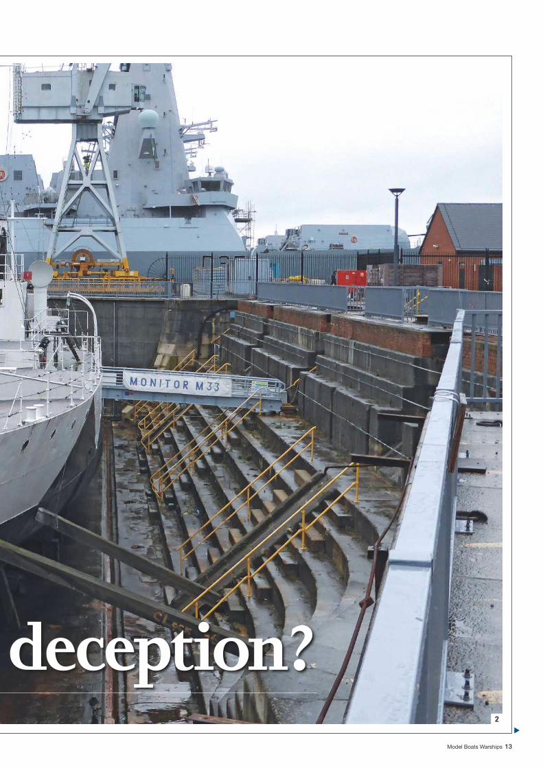
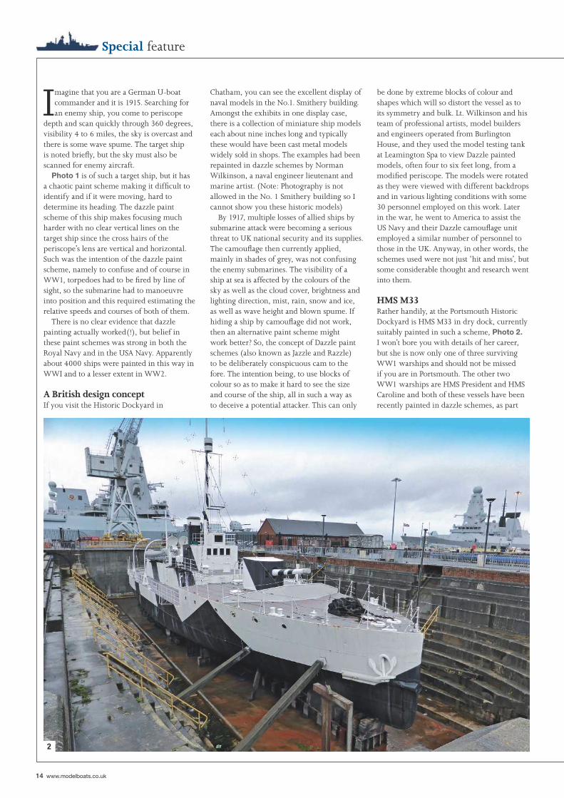
HMS M33Rather handily, at the Portsmouth Historic Dockyard is HMS M33 in dry dock, currently suitably painted in such a scheme, Photo 2. I won’t bore you with details of her career, but she is now only one of three surviving WW1 warships and should not be missed if you are in Portsmouth. The other two WW1 warships are HMS President and HMS Caroline and both of these vessels have been recently painted in dazzle schemes, as part
Chatham, you can see the excellent display of naval models in the No.1. Smithery building. Amongst the exhibits in one display case, there is a collection of miniature ship models each about nine inches long and typically these would have been cast metal models widely sold in shops. The examples had been repainted in dazzle schemes by Norman Wilkinson, a naval engineer lieutenant and marine artist. (Note: Photography is not allowed in the No. 1 Smithery building so I cannot show you these historic models)
By 1917, multiple losses of allied ships by submarine attack were becoming a serious threat to UK national security and its supplies. The camoufl age then currently applied, mainly in shades of grey, was not confusing the enemy submarines. The visibility of a ship at sea is affected by the colours of the sky as well as the cloud cover, brightness and lighting direction, mist, rain, snow and ice, as well as wave height and blown spume. If hiding a ship by camoufl age did not work, then an alternative paint scheme might work better? So, the concept of Dazzle paint schemes (also known as Jazzle and Razzle) to be deliberately conspicuous cam to the fore. The intention being, to use blocks of colour so as to make it hard to see the size and course of the ship, all in such a way as to deceive a potential attacker. This can only
Imagine that you are a German U-boat commander and it is 1915. Searching for an enemy ship, you come to periscope
depth and scan quickly through 360 degrees, visibility 4 to 6 miles, the sky is overcast and there is some wave spume. The target ship is noted briefl y, but the sky must also be scanned for enemy aircraft.
Photo 1 is of such a target ship, but it has a chaotic paint scheme making it diffi cult to identify and if it were moving, hard to determine its heading. The dazzle paint scheme of this ship makes focusing much harder with no clear vertical lines on the target ship since the cross hairs of the periscope’s lens are vertical and horizontal. Such was the intention of the dazzle paint scheme, namely to confuse and of course in WW1, torpedoes had to be fi red by line of sight, so the submarine had to manoeuvre into position and this required estimating the relative speeds and courses of both of them.
There is no clear evidence that dazzle painting actually worked(!), but belief in these paint schemes was strong in both the Royal Navy and in the USA Navy. Apparently about 4000 ships were painted in this way in WWI and to a lesser extent in WW2.
A British design conceptIf you visit the Historic Dockyard in
Special feature
2
Model Boats Warships 15
topped main deck, just having a small pilot house (conning tower) that could be raised and lowered when needed. Trials soon began on procedures for aircraft handling and on arrestor wire systems and here she is shown in her dazzle paint scheme. In WW2 she served with distinction, delivering aircraft to Malta, the Gold Coast, Iceland and Mur-
of the celebrations of the centenary of the start of WW1. HMS President was originally HMS Saxifrage, a Flower class anti-submarine Q-ship built in 1918 and mounting 4 inch and 6pdr guns plus depth charges, but disguised as a coastal merchant ship. The idea being that a U-boat would not want to sacrifi ce a valuable torpedo on a small coaster, so would attack her on the surface using guns to sink the ship. However, the plan was that HMS Saxifrage would expose her guns at the critical moment and in turn, attack the submarine! As HMS President, she is moored at Blackfriars on the Thames in London. HMS Caroline was a WW1 C-class light cruiser and is currently moored in Belfast.
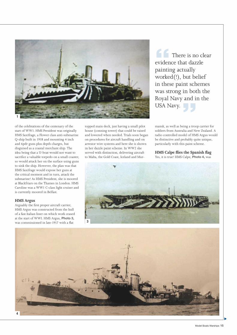
HMS ArgusArguably the fi rst proper aircraft carrier, HMS Argus was constructed from the hull of a fast Italian liner on which work ceased at the start of WWI. HMS Argus, Photo 3, was commissioned in late-1917 with a fl at
1
3
4
mansk, as well as being a troop carrier for soldiers from Australia and New Zealand. A radio controlled model of HMS Argus would be distinctive and probably quite unique, particularly with this paint scheme.
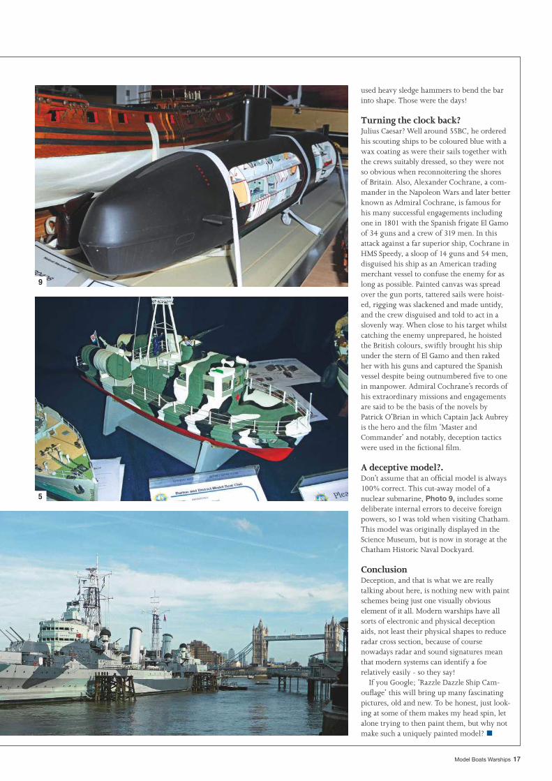
HMS Calpe fl ies the Spanish fl agYes, it is true! HMS Calpe, Photo 4, was
“ There is no clear evidence that dazzle painting actually worked(!), but belief in these paint schemes was strong in both the Royal Navy and in the USA Navy. ”

16 www.modelboats.co.uk
HMS BelfastThis is the last surviving WW2 RN warship and was painted in a deceptive scheme for 2014, Photo 7. Okay, maybe not as dramatic as some schemes, but deception is the name of the game. The dazzle scheme is also markedly different on the starboard side, Photo 8. Again, I shall not bore you with a history of this famous vessel’s career that stretched from 1939 to 1963, but suffi ce to say she had a sister, HMS Edinburgh and they were both lengthened Town class cruisers, the latter being lost in combat. Thankfully she has been preserved with the help of public fund raising and is now part of the National Historic Fleet, Core Collection, managed here by the Imperial War Museum. A visit to the ship is recommended and includes excellent audio visual fi lm effects inside Y turret.
Whilst on board I noted the heavy duty anchor chain and I well remember in 1955 visiting Rosyth Naval Dockyard and seeing anchor chain being made. Straight out of Victorian times in the glow of the huge blacksmiths forge, four men were stripped to the waist, one holding with giant tongs the red hot section of bar, whilst the other three
disguised as a Spanish ship with the crew kept out of sight as she steamed into the French port of St. Jean de Luz on 4th April 1942. Lowering the Spanish fl ag and replacing it with the White Ensign she opened fi re, bombarding the town in order to take off some Polish soldiers. HMS Calpe was a Hunt class destroyer, and saw action off North Africa and in the ill-fated Dieppe raid.
FrunzyakaThe Coastal Defence Vessel Frunzyaka, Photo 5, is a splendid example of a dazzle paint scheme on a Soviet Union Baltic Sea missile armed vessel. This fi ne and unusual model was exhibited by Moira Hawkins at a Coalville Model Boat Show.
Deans Marine Open DaysThis splendid model, Photo 6, was displayed in 2012, but unfortunately I did not note the name of the builder. This Rodney class battleship was not complete but when photo-graphed against the backdrop of a grey canvas screen and with the hull below the waterline hidden from view, the model’s outline does start to become quite indistinct.
Special feature
6
78
“ Julius Caesar? Well around 55BC, he ordered his scouting ships to be coloured blue with a wax coating as were their sails together with the crews suitably dressed, so they were not so obvious when reconnoitering the shores of Britain. ”
Model Boats Warships 17
used heavy sledge hammers to bend the bar into shape. Those were the days!
Turning the clock back?Julius Caesar? Well around 55BC, he ordered his scouting ships to be coloured blue with a wax coating as were their sails together with the crews suitably dressed, so they were not so obvious when reconnoitering the shores of Britain. Also, Alexander Cochrane, a com-mander in the Napoleon Wars and later better known as Admiral Cochrane, is famous for his many successful engagements including one in 1801 with the Spanish frigate El Gamo of 34 guns and a crew of 319 men. In this attack against a far superior ship, Cochrane in HMS Speedy, a sloop of 14 guns and 54 men, disguised his ship as an American trading merchant vessel to confuse the enemy for as long as possible. Painted canvas was spread over the gun ports, tattered sails were hoist-ed, rigging was slackened and made untidy, and the crew disguised and told to act in a slovenly way. When close to his target whilst catching the enemy unprepared, he hoisted the British colours, swiftly brought his ship under the stern of El Gamo and then raked her with his guns and captured the Spanish vessel despite being outnumbered fi ve to one in manpower. Admiral Cochrane’s records of his extraordinary missions and engagements are said to be the basis of the novels by Patrick O’Brian in which Captain Jack Aubrey is the hero and the fi lm ‘Master and Commander’ and notably, deception tactics were used in the fi ctional fi lm.
A deceptive model?.Don’t assume that an offi cial model is always 100% correct. This cut-away model of a nuclear submarine, Photo 9, includes some deliberate internal errors to deceive foreign powers, so I was told when visiting Chatham. This model was originally displayed in the Science Museum, but is now in storage at the Chatham Historic Naval Dockyard.
ConclusionDeception, and that is what we are really talking about here, is nothing new with paint schemes being just one visually obvious element of it all. Modern warships have all sorts of electronic and physical deception aids, not least their physical shapes to reduce radar cross section, because of course nowadays radar and sound signatures mean that modern systems can identify a foe relatively easily - so they say!
If you Google; ‘Razzle Dazzle Ship Cam-oufl age’ this will bring up many fascinating pictures, old and new. To be honest, just look-ing at some of them makes my head spin, let alone trying to then paint them, but why not make such a uniquely painted model? ■
5
9
Side view of the 55ft CMB at Chatham Historic Dockyard (Photo courtesy of Colin Bishop).
18 www.modelboats.co.uk
WW1 coastal motor boats
WW1 coastalmotor boatsCoastal motor boats performed a vital role in attackingGerman naval Coastal motor boats performed a vital role in attackingGerman naval bases and shipping. IVOR WARNE takes a look at the survivorsbases and shipping. IVOR WARNE takes a look at the survivors
Model Boats Warships 19
ConstructionThis was of mahogany plank-on-frame, with a single step planing round form hull. The 40ft CMB had an 8ft 6ins beam and displaced fi ve tons with a draught of 2ft 9ins. The stepped hydroplane design lessened the wetted area of the boat in the water and so reduced drag and allowed a higher speed. The wetted area was lessened because as the boat increased speed through the water, it would lift the hull up on to the step, thus raising a large proportion of the hull out of the water.
Power was provided by a V12 Thornycroft petrol engine developing 275bhp through a single propeller shaft. The engine was adapted from an aero unit and in the interests of weight saving there was no reverse gearbox. In the end, a total of 39 were built and they carried a variety of armaments, which included:
• 18 inch torpedo• Depth charges• Mines• Machine guns, e.g. Lewis guns
History of the coastal motor boat
The Coastal Motor Boats (CMBs) were developed at the suggestion of young naval offi cers of the Harwich destroyer force in 1915. Their proposal was to use fast racing boats to skim over German minefi elds and then attack the German naval bases and shipping. The CMB designation was used to disguise their ultimate purpose. The Admiralty adopted the suggestion and put out a specifi cation for a vessel that would:• Carry an 18 inch torpedo
• Have a maximum speed of 30 • knots Carry suffi cient petrol to give a wide radius of action• Weigh less than 4.5 tons so that it could be davit launched from light cruisersThe method of deploying from light cruisers was soon abandoned and the weight gradually increased with the addition of performance improving developments. John I. Thornycroft of Hampton-on-Thames, developed a design to meet this
demanding specifi cation. Twelve were ordered in 1916 and delivered to the Royal Navy within seven months. The design stemmed from a 1910 Thornycroft speedboat called Miranda IV, which was a 25 feet long, single step hydroplane powered by a 120hp Thornycroft petrol engine and that could reach 35 knots. So, this was the basis for the 40 foot design that was accepted by the Admiralty.
Below: Stern view of CMB No.4 showing torpedo trough.
Above: Samson post at the stern.
20 www.modelboats.co.uk
WW1 coastal motor boats
Operational challengesIn order to keep the weight down, the torpedo could not be fi red from a tube. Instead it was carried in a rear facing trough. To fi re the torpedo, it was pushed backwards out of the vessel by a cordite fi ring pistol and a long steel ram, to enter the water tail fi rst and already running. The CMB would then swiftly turn away from the target to give the torpedo a clear run. There is no record of a CMB being hit by its own torpedo, but it was defi nitely a hairy way to earn a living! In the interests of further weight saving, the boats were quite basic and must have been demanding to operate, crew comfort not being a major consideration. However, they did get the luxury of a spray defl ection screen in front of the cockpit.
Without hydraulics or any sort of power steering to operate the rudder, the only assistance for the coxswain was provided by his muscles and a system of levers and linkages. The choice of petrol engine with a wooden hull is always a tricky combination for any warship, no matter how big or small. The CMBs were particularly vulnerable to aeroplane attack and if hit they would certainly burn well.
In actionThe largest CMB base was on Osea Island in the River Blackwater, Essex ( near to Maldon). At Duxford (just off the M11 near Cambridge) you can see a fi lm clip of the early boats being operated from this base.
The fi rst group of CMBs were deployed off the Belgian coast in 1916 operating from a forward base at Dunkirk. In 1917, Lt W.N.T. Beckett attacked the German destroyers in Zeebrugge Harbour and managed to sink one and damage another. For this he was mentioned in dispatches and awarded the Distinguished Service Cross. In 1918 they saw major action again off Zeebrugge and Ostend where they laid a smokescreen to cover the approach of block ships that were going to be sunk at the harbour entrances.
CMB No. 4, the preserved example at Duxford, was used in action by ‘The Mystery VC’. His identity was suppressed initially as he was involved in secret operations instigated by the British Government to suppress the Russian Revolution. His identity was later revealed to be Lieutenant (subsequently Captain) Augustus Agar. He established a base at Terrioki on the north shore of Petrograd Bay in the Baltic. He used two CMBs to land secret agents near Petrograd to spy on the Bolsheviks. In 1919 there were nine such operations to either drop off or pick up agents (James Bond 007 eat your heart out!), seven of which involved Lieutenant Agar.
He followed up this activity in June 1919 with an attack, using CMB No.4, on the Soviet Cruiser Oleg, which was besieging dissident
rebels at Krasnaya Gorka near the Bolshevik base of Kronstadt. Despite problems with the premature ignition of the cordite launching charge, he slipped past the destroyer screen to sink the cruiser. For this he was awarded the Victoria Cross, known as ‘The Mystery VC’.
In August 1919, Commander Dobson and Lieutenant Agar (now in CMB No.7) led seven of the new larger 55ft CMBs on a night raid into Kronstadt Harbour. One broke down and had to be left behind. The group succeeded in sinking the battleships Andrei Pervozvanni and Petropavlovsk, plus the submarine depot ship Pamiat Azova. For the loss of three CMBs, the battle fl eet had effectively been destroyed. Agar received the Distinguished Service Order for his part in the action and Cmdr. Dobson and Sub-Lt. Steel received the Victoria Cross.
The Russians were now well aware of the CMBs and their potential for surprise attacks. Despite this, in September 1919, Lt. Agar led two 55ft CMBs in his CMB No.4 to lay mines in the approaches to Kronstadt Harbour, but
unfortunately he was spotted and the mines were safely swept with no damage done. Nevertheless, the CMBs had punched well above their weight to achieve spectacular successes against signifi cant targets.
“ In 1918 they saw major action again off Zeebrugge and Ostend where they laid a smokescreen to cover the approach of block ships that were going to be sunk at the harbour entrances. ”
Above: CMB No.4 bow fi tting. Above: Model of a 55ft CMB at Duxford.
Above: The step of the stepped hydroplane hull.
Below: The rudder operating mechanism – just muscle strength required.
Model Boats Warships 21
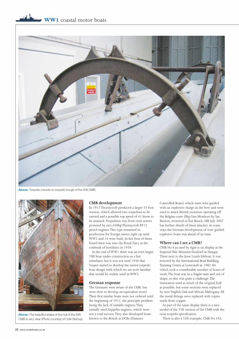
Above: Torpedo mounts on torpedo trough of the 40ft CMB.
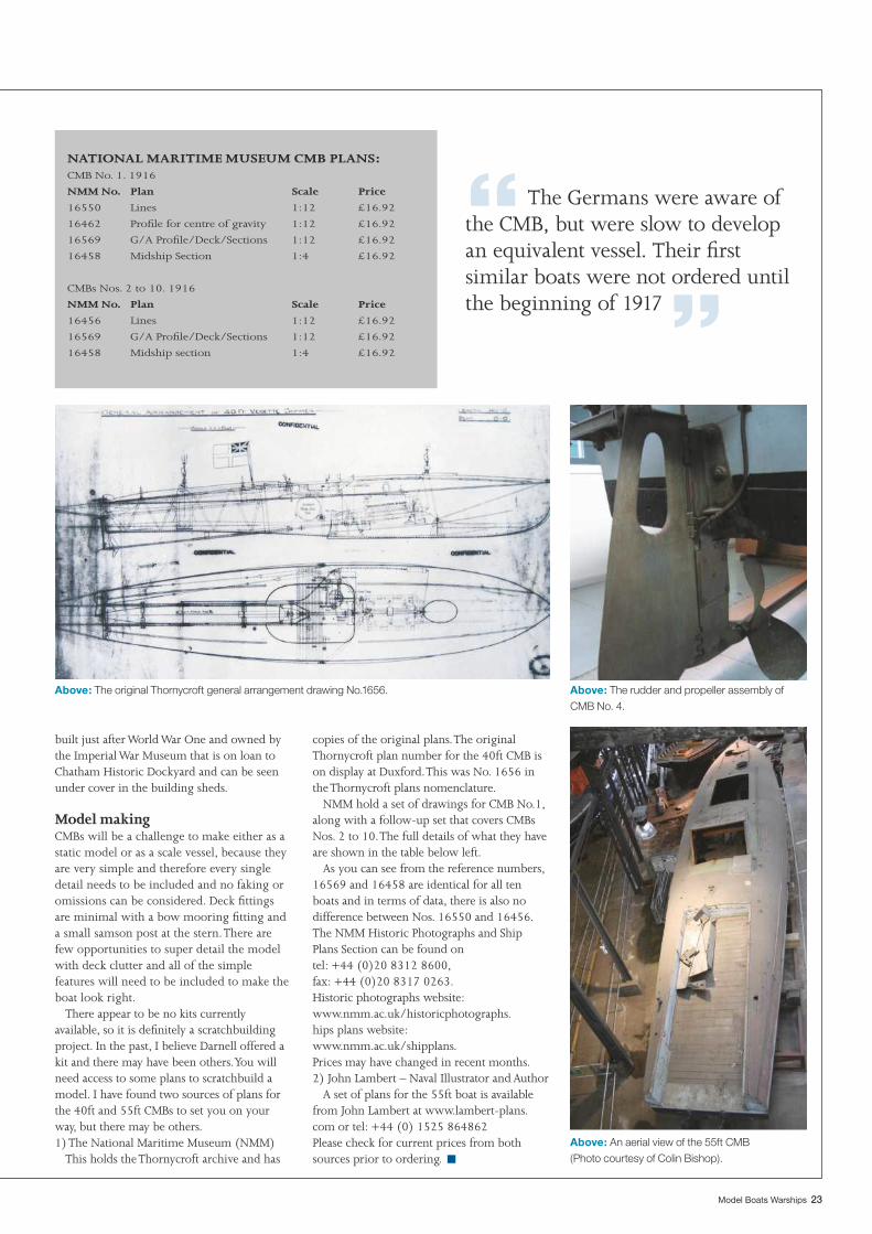
Above: The beautiful shape of the hull of the 55ft CMB is very clear (Photo courtesy of Colin Bishop).
22 www.modelboats.co.uk
WW1 coastal motor boats
CMB developmentIn 1917 Thornycroft produced a larger 55 foot version, which allowed two torpedoes to be carried and a possible top speed of 41 knots to be attained. Propulsion was from twin screws powered by two 650hp Thornycroft RY12 petrol engines. This type remained in production for foreign navies right up until WW2 and 14 were built. In fact four of them found their way into the Royal Navy at the outbreak of hostilities in 1939.
At the end of WW1 there was an even larger 70ft boat under construction as a fast minelayer, but it was not until 1936 that Vosper started to develop the motor torpedo boat design with which we are now familiar that would be widely used in WW2.
German responseThe Germans were aware of the CMB, but were slow to develop an equivalent vessel. Their fi rst similar boats were not ordered until the beginning of 1917, the principle problem being the lack of suitable engines. They initially used Zeppelin engines, which were not a total success. They also developed boats known to the British as DCBs (Distance
Controlled Boats) which were wire guided with an explosive charge in the bow and were used to attack British monitors operating off the Belgian coast (Big Gun Monitors by Ian Buxton, reviewed in Test Bench, MB July 2007 has further details of these attacks). In some ways the German development of wire guided explosive boats was ahead of its time.
Where can I see a CMB?CMB No.4 as used by Agar is on display at the Imperial War Museum Duxford in Hangar Three next to the Jesse Lumb lifeboat. It was restored by the International Boat Building Training Centre at Lowestoft in 1982-84 which took a considerable number of hours of work. The boat was in a fragile state and out of shape, so this was quite a challenge. The restoration used as much of the original hull as possible, but some sections were replaced by new English Oak and African Mahogany. All the metal fi ttings were replaced with copies made from copper.
As part of the same display there is a nice model of the 55ft version of the CMB with the twin torpedo specifi cation.
There is also a 55ft example, CMB No.103,
“ The Germans were aware of the CMB, but were slow to develop an equivalent vessel. Their fi rst similar boats were not ordered until the beginning of 1917 ”
Above: An aerial view of the 55ft CMB (Photo courtesy of Colin Bishop).
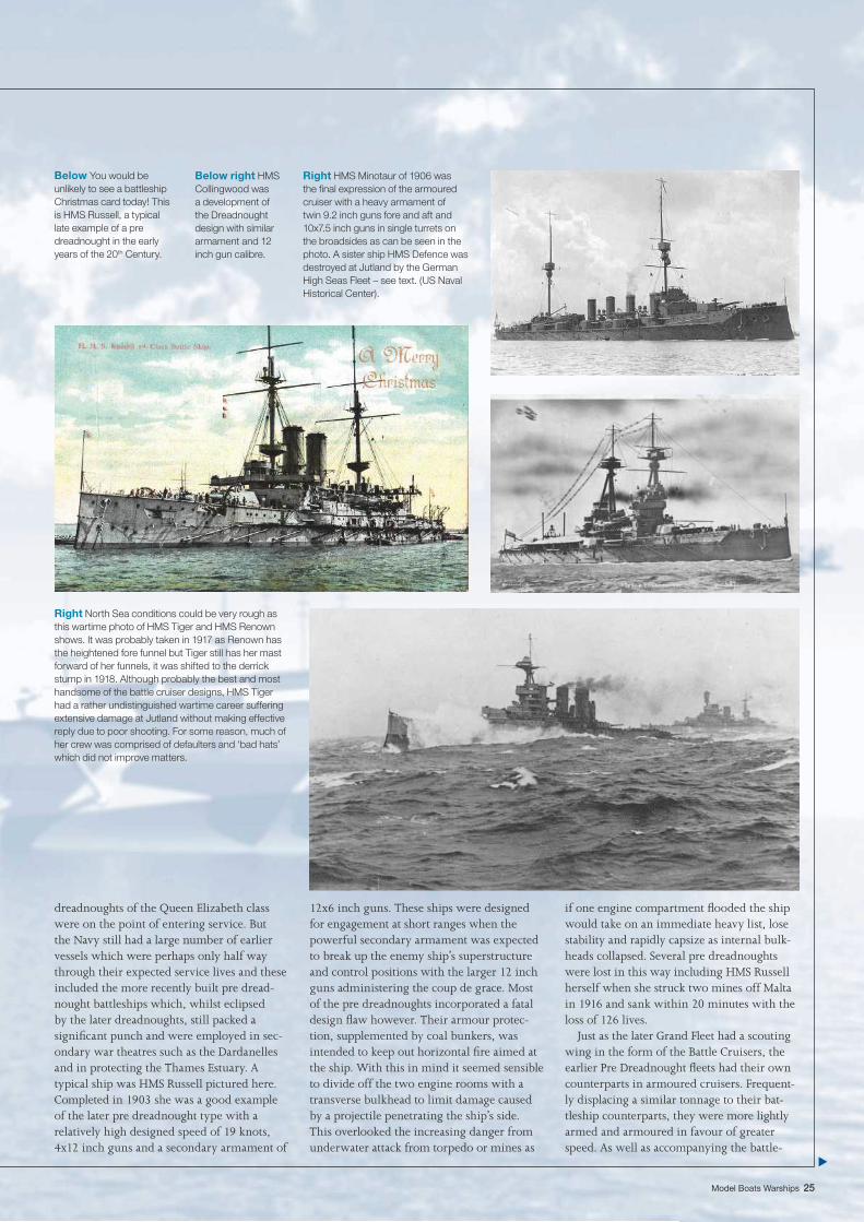
Above: The rudder and propeller assembly of CMB No. 4.
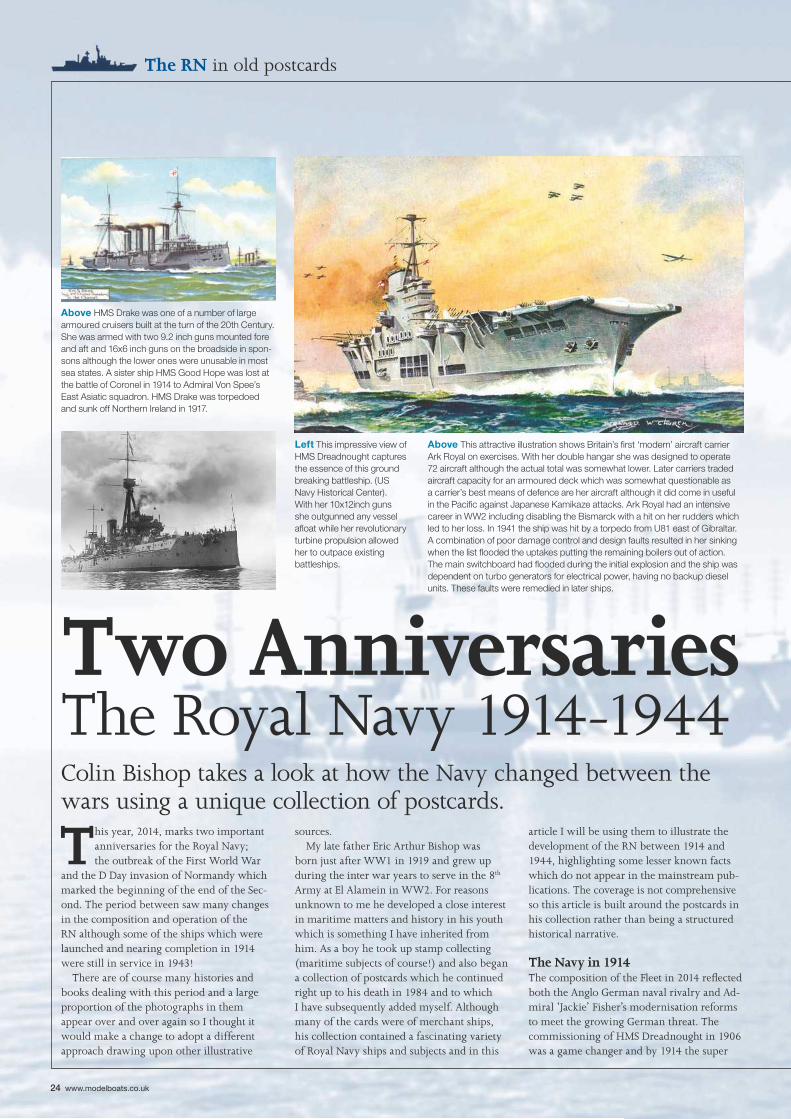
Above: The original Thornycroft general arrangement drawing No.1656.
NATIONAL MARITIME MUSEUM CMB PLANS:CMB No. 1. 1916
NMM No. Plan Scale Price
16550 Lines 1:12 £16.92
16462 Profi le for centre of gravity 1:12 £16.92
16569 G/A Profi le/Deck/Sections 1:12 £16.92
16458 Midship Section 1:4 £16.92
CMBs Nos. 2 to 10. 1916
NMM No. Plan Scale Price
16456 Lines 1:12 £16.92
16569 G/A Profi le/Deck/Sections 1:12 £16.92
16458 Midship section 1:4 £16.92
■
Model Boats Warships 23
built just after World War One and owned by the Imperial War Museum that is on loan to Chatham Historic Dockyard and can be seen under cover in the building sheds.
Model makingCMBs will be a challenge to make either as a static model or as a scale vessel, because they are very simple and therefore every single detail needs to be included and no faking or omissions can be considered. Deck fi ttings are minimal with a bow mooring fi tting and a small samson post at the stern. There are few opportunities to super detail the model with deck clutter and all of the simple features will need to be included to make the boat look right.
There appear to be no kits currently available, so it is defi nitely a scratchbuilding project. In the past, I believe Darnell offered a kit and there may have been others. You will need access to some plans to scratchbuild a model. I have found two sources of plans for the 40ft and 55ft CMBs to set you on your way, but there may be others.1) The National Maritime Museum (NMM)
This holds the Thornycroft archive and has
copies of the original plans. The original Thornycroft plan number for the 40ft CMB is on display at Duxford. This was No. 1656 in the Thornycroft plans nomenclature.
NMM hold a set of drawings for CMB No.1, along with a follow-up set that covers CMBs Nos. 2 to 10. The full details of what they have are shown in the table below left.
As you can see from the reference numbers, 16569 and 16458 are identical for all ten boats and in terms of data, there is also no difference between Nos. 16550 and 16456. The NMM Historic Photographs and Ship Plans Section can be found ontel: +44 (0)20 8312 8600, fax: +44 (0)20 8317 0263.Historic photographs website:www.nmm.ac.uk/historicphotographs. hips plans website:www.nmm.ac.uk/shipplans.Prices may have changed in recent months.2) John Lambert – Naval Illustrator and Author
A set of plans for the 55ft boat is available from John Lambert at www.lambert-plans.com or tel: +44 (0) 1525 864862Please check for current prices from both sources prior to ordering.
24 www.modelboats.co.uk
The RN in old postcards
This year, 2014, marks two important anniversaries for the Royal Navy; the outbreak of the First World War
and the D Day invasion of Normandy which marked the beginning of the end of the Sec-ond. The period between saw many changes in the composition and operation of the RN although some of the ships which were launched and nearing completion in 1914 were still in service in 1943!
There are of course many histories and books dealing with this period and a large proportion of the photographs in them appear over and over again so I thought it would make a change to adopt a different approach drawing upon other illustrative
sources.My late father Eric Arthur Bishop was
born just after WW1 in 1919 and grew up during the inter war years to serve in the 8th Army at El Alamein in WW2. For reasons unknown to me he developed a close interest in maritime matters and history in his youth which is something I have inherited from him. As a boy he took up stamp collecting (maritime subjects of course!) and also began a collection of postcards which he continued right up to his death in 1984 and to which I have subsequently added myself. Although many of the cards were of merchant ships, his collection contained a fascinating variety of Royal Navy ships and subjects and in this
article I will be using them to illustrate the development of the RN between 1914 and 1944, highlighting some lesser known facts which do not appear in the mainstream pub-lications. The coverage is not comprehensive so this article is built around the postcards in his collection rather than being a structured historical narrative.
The Navy in 1914The composition of the Fleet in 2014 refl ected both the Anglo German naval rivalry and Ad-miral ‘Jackie’ Fisher’s modernisation reforms to meet the growing German threat. The commissioning of HMS Dreadnought in 1906 was a game changer and by 1914 the super
Two Anniversaries The Royal Navy 1914-1944Colin Bishop takes a look at how the Navy changed between the wars using a unique collection of postcards.
Above HMS Drake was one of a number of large armoured cruisers built at the turn of the 20th Century. She was armed with two 9.2 inch guns mounted fore and aft and 16x6 inch guns on the broadside in spon-sons although the lower ones were unusable in most sea states. A sister ship HMS Good Hope was lost at the battle of Coronel in 1914 to Admiral Von Spee’s East Asiatic squadron. HMS Drake was torpedoed and sunk off Northern Ireland in 1917.
Above This attractive illustration shows Britain’s fi rst ‘modern’ aircraft carrier Ark Royal on exercises. With her double hangar she was designed to operate 72 aircraft although the actual total was somewhat lower. Later carriers traded aircraft capacity for an armoured deck which was somewhat questionable as a carrier’s best means of defence are her aircraft although it did come in useful in the Pacifi c against Japanese Kamikaze attacks. Ark Royal had an intensive career in WW2 including disabling the Bismarck with a hit on her rudders which led to her loss. In 1941 the ship was hit by a torpedo from U81 east of Gibraltar. A combination of poor damage control and design faults resulted in her sinking when the list fl ooded the uptakes putting the remaining boilers out of action. The main switchboard had fl ooded during the initial explosion and the ship was dependent on turbo generators for electrical power, having no backup diesel units. These faults were remedied in later ships.
Left This impressive view of HMS Dreadnought captures the essence of this ground breaking battleship. (US Navy Historical Center). With her 10x12inch guns she outgunned any vessel afl oat while her revolutionary turbine propulsion allowed her to outpace existing battleships.
Model Boats Warships 25
dreadnoughts of the Queen Elizabeth class were on the point of entering service. But the Navy still had a large number of earlier vessels which were perhaps only half way through their expected service lives and these included the more recently built pre dread-nought battleships which, whilst eclipsed by the later dreadnoughts, still packed a signifi cant punch and were employed in sec-ondary war theatres such as the Dardanelles and in protecting the Thames Estuary. A typical ship was HMS Russell pictured here. Completed in 1903 she was a good example of the later pre dreadnought type with a relatively high designed speed of 19 knots, 4x12 inch guns and a secondary armament of
12x6 inch guns. These ships were designed for engagement at short ranges when the powerful secondary armament was expected to break up the enemy ship’s superstructure and control positions with the larger 12 inch guns administering the coup de grace. Most of the pre dreadnoughts incorporated a fatal design fl aw however. Their armour protec-tion, supplemented by coal bunkers, was intended to keep out horizontal fi re aimed at the ship. With this in mind it seemed sensible to divide off the two engine rooms with a transverse bulkhead to limit damage caused by a projectile penetrating the ship’s side. This overlooked the increasing danger from underwater attack from torpedo or mines as
if one engine compartment fl ooded the ship would take on an immediate heavy list, lose stability and rapidly capsize as internal bulk-heads collapsed. Several pre dreadnoughts were lost in this way including HMS Russell herself when she struck two mines off Malta in 1916 and sank within 20 minutes with the loss of 126 lives.
Just as the later Grand Fleet had a scouting wing in the form of the Battle Cruisers, the earlier Pre Dreadnought fl eets had their own counterparts in armoured cruisers. Frequent-ly displacing a similar tonnage to their bat-tleship counterparts, they were more lightly armed and armoured in favour of greater speed. As well as accompanying the battle-
Below You would be unlikely to see a battleship Christmas card today! This is HMS Russell, a typical late example of a pre dreadnought in the early years of the 20th Century.
Right HMS Minotaur of 1906 was the fi nal expression of the armoured cruiser with a heavy armament of twin 9.2 inch guns fore and aft and 10x7.5 inch guns in single turrets on the broadsides as can be seen in the photo. A sister ship HMS Defence was destroyed at Jutland by the German High Seas Fleet – see text. (US Naval Historical Center).
Below right HMS Collingwood was a development of the Dreadnought design with similar armament and 12 inch gun calibre.
Right North Sea conditions could be very rough as this wartime photo of HMS Tiger and HMS Renown shows. It was probably taken in 1917 as Renown has the heightened fore funnel but Tiger still has her mast forward of her funnels, it was shifted to the derrick stump in 1918. Although probably the best and most handsome of the battle cruiser designs, HMS Tiger had a rather undistinguished wartime career suffering extensive damage at Jutland without making effective reply due to poor shooting. For some reason, much of her crew was comprised of defaulters and ‘bad hats’ which did not improve matters.
26 www.modelboats.co.uk
The RN in old postcards
fl eet, they were also intended to act as ‘Ships of Force’ on foreign stations, able to match potential enemies for speed and bring to bear overwhelming fi repower. Here we have two examples of the type. HMS Drake was one of a number of broadly similar ships and was armed with 9.2 inch guns fore and aft with a broadside battery of no less than 16x6 inch guns in casemates although those in the low-er positions could not be worked in a seaway due to fl ooding. A sister ship, HMS Good Hope was lost at the battle of Coronel when manned by relatively untrained reservists. Outranged and in a hopeless tactical position, she succumbed to Admiral Von Spee’s more modern and regular navy manned armoured cruisers Scharnhorst and Gneisenau.
The later armoured cruisers were quite powerful vessels as the illustration of HMS
This period is very well supported by the mod-
elling trade, particularly in respect of Royal
Navy ships. The list below is not exhaustive.
Just about everything is available ranging from
plans, kits, hulls, and fi ttings and there are
even some Almost Ready to Run models such
as Graupner’s HMS Hood to 1:150 scale if your
pockets are deep enough!
■ If you are building from scratch then the
Model Boats Plans Service has an excellent
selection to choose from.
www.myhobbystore.co.uk/
■ John Lambert Plans, www.feralchicken.
co.uk/lambert-plans offer accurate drawings of
WW2 period ships of destroyer size and below.
■ Deans Marine www.deansmarine.co.uk/
have excellent coverage with their wide range
of kits and hulls which include ships of the
pre dreadnought era, HMS Dreadnought
herself, hulls for Nelson & Rodney and the King
George V class battleships and examples of
most of the destroyer classes which served
in WW2.
Modelling resources ■ Fleetscale www.fl eetscale.com/store/ are well
known for their high quality products and offer
a semi kit for the last of the pre Dreadnoughts
Lord Nelson plus hulls for many of the major
warships of the Inter War and WW2 periods.
■ Models by Design www.modelsbydesign.
co.uk/ offer hulls for HMS Dreadnought and
HMS Warspite.
■ John Haynes, www.johnrhaynes.com is well
known for his extensive range of fi ttings for
WW2 period ships and his museum quality
hulls for various warships are now marketed
through Fleetscale.
■ Nautical Marine Models
www.nauticalmarinemodels.co.uk/ also offer
a range of naval fi ttings.
■ White Ensign Models
mwww.whiteensignmodels.com/, although
primarily known for their authentic paints, also
supply naval fi ttings in the form of photo etch.
■ For more information check out the supplier
advertisements in Model Boats magazine and
on the Model Boats Website
www.modelboats.co.uk
Right Admiral Jellicoe’s fl agship HMS Iron Duke was the fi nal development of the Dreadnought design. Her 13.5 inch main and 6 inch secondary armament made her a much more powerful and effective antagonist. Later ships with 15 inch guns were to be known as super dreadnoughts.
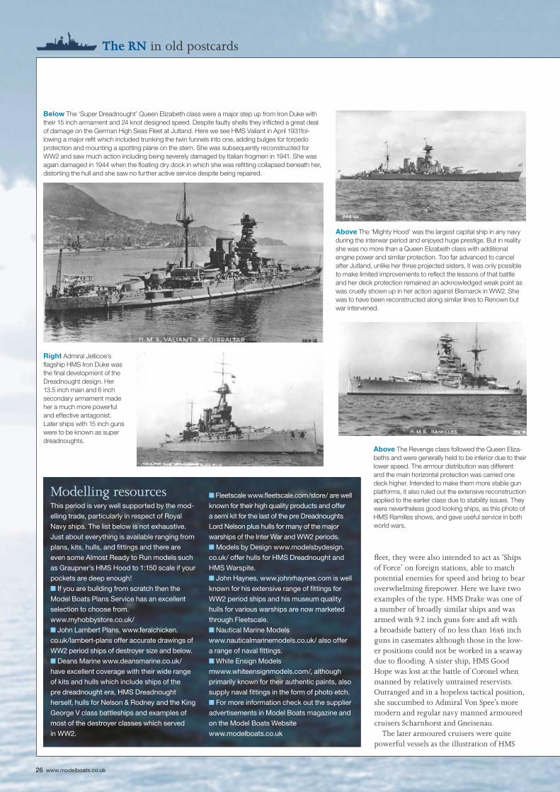
Below The ‘Super Dreadnought’ Queen Elizabeth class were a major step up from Iron Duke with their 15 inch armament and 24 knot designed speed. Despite faulty shells they infl icted a great deal of damage on the German High Seas Fleet at Jutland. Here we see HMS Valiant in April 1931fol-lowing a major refi t which included trunking the twin funnels into one, adding bulges for torpedo protection and mounting a spotting plane on the stern. She was subsequently reconstructed for WW2 and saw much action including being severely damaged by Italian frogmen in 1941. She was again damaged in 1944 when the fl oating dry dock in which she was refi tting collapsed beneath her, distorting the hull and she saw no further active service despite being repaired.
Above The Revenge class followed the Queen Eliza-beths and were generally held to be inferior due to their lower speed. The armour distribution was different and the main horizontal protection was carried one deck higher. Intended to make them more stable gun platforms, it also ruled out the extensive reconstruction applied to the earlier class due to stability issues. They were nevertheless good looking ships, as this photo of HMS Ramilles shows, and gave useful service in both world wars.
Above The ‘Mighty Hood’ was the largest capital ship in any navy during the interwar period and enjoyed huge prestige. But in reality she was no more than a Queen Elizabeth class with additional engine power and similar protection. Too far advanced to cancel after Jutland, unlike her three projected sisters, it was only possible to make limited improvements to refl ect the lessons of that battle and her deck protection remained an acknowledged weak point as was cruelly shown up in her action against Bismarck in WW2. She was to have been reconstructed along similar lines to Renown but war intervened.
Model Boats Warships 27
Minotaur shows and carried a heavy arma-ment of 4x9.2 inch guns in twin turrets fore and aft plus 10x7.5 inch on the broadside, all in single turrets. They were still no match for modern battleships and battlecruisers as was cruelly exposed at Jutland when HMS Defence of the class was rashly taken into range of the High Seas Fleet by Rear Admiral Arbuthnot and rapidly obliterated. At the time the ship was thought to have been almost in-stantaneously blown to pieces but subsequent discovery of the wreck showed it to be largely intact. Again there were design vulnerabilities in that the 7.5 inch guns were served by connecting ammunition passages and it was observed that the 7.5 inch turrets exploded in rapid succession following the detonation of one of the 9.2 inch magazines as fi re and explosions spread through the ship. The state
of the wreck suggests that the bow and stern were blown off by the 9.2 inch magazines exploding leaving the centre section of the ship on the seabed as discovered. There were no survivors from over 900 crew.
As something of an aside, there is a lot of information on the Internet concerning the Jutland battle wrecks, many of which are still substantially intact. Just Google ‘Jutland Wrecks’.
The Dreadnought eraDreadnought herself was a ‘one off’ but she was followed by a succession of classes of similar ships with improved armour and armament layout but still armed with the successful 12 inch gun. HMS Collingwood was a typical example. When their German counterparts moved from the 11 inch to
the 12 inch gun, the British ships went one better with the 13.5 inch, another very effective weapon which was also fi tted to the Lion class battlecruisers. Admiral Jellicoe’s fl agship, Iron Duke, belonged to the last class of 13.5 inch gun equipped dreadnoughts. The next class of battleships represented a quantum step forward. Queen Elizabeth and her sisters were armed with 15 inch guns fi ring a shell of 1,950lbs compared with the maximum shell weight of 1,400lb of the ear-lier gun. With just 8 twin turrets, enhanced armour and a three knot speed increase over the standard fl eet speed from their oil fi red machinery, the QEs were in a class of their own and are generally considered to have been among the most successful warship designs of all time with distinguished service in both World Wars. At Jutland the class
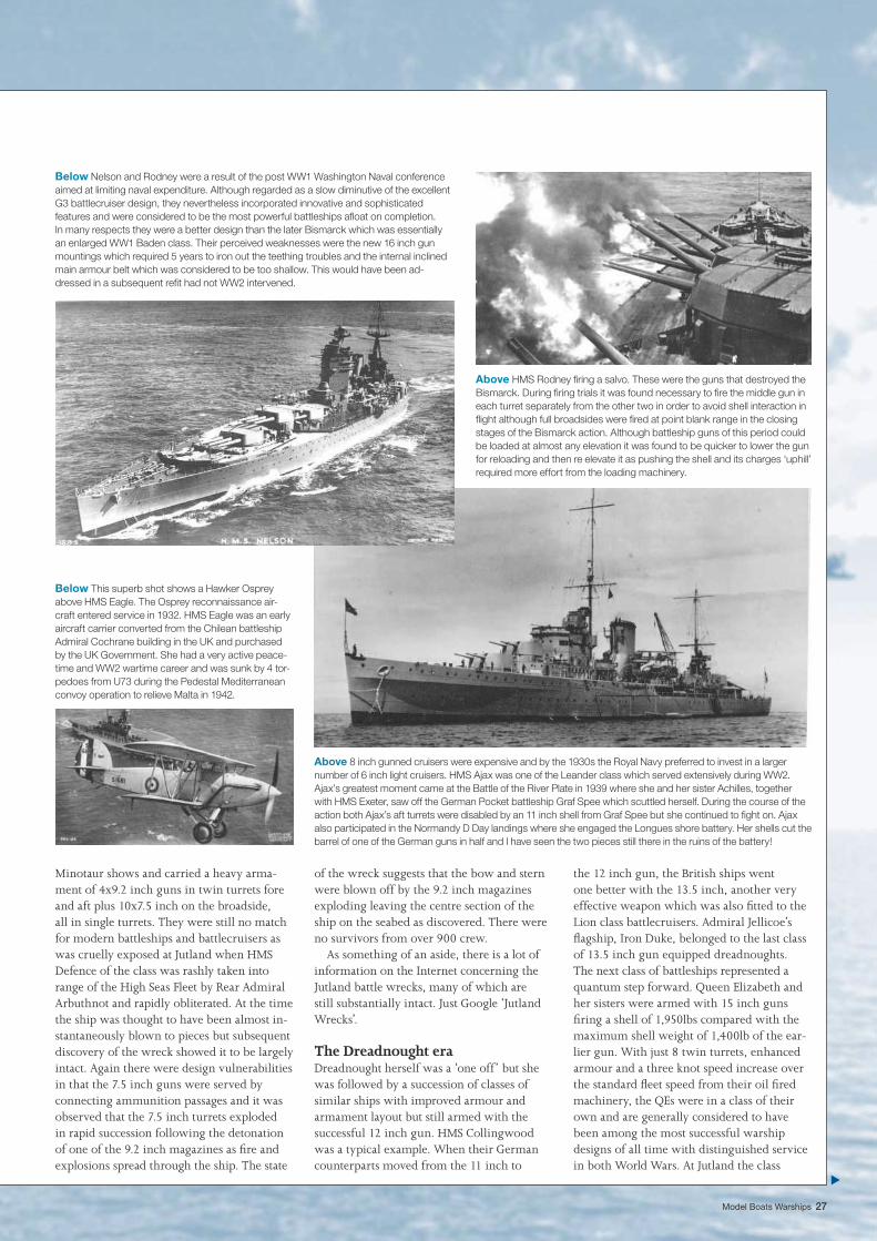
Below Nelson and Rodney were a result of the post WW1 Washington Naval conference aimed at limiting naval expenditure. Although regarded as a slow diminutive of the excellent G3 battlecruiser design, they nevertheless incorporated innovative and sophisticated features and were considered to be the most powerful battleships afl oat on completion. In many respects they were a better design than the later Bismarck which was essentially an enlarged WW1 Baden class. Their perceived weaknesses were the new 16 inch gun mountings which required 5 years to iron out the teething troubles and the internal inclined main armour belt which was considered to be too shallow. This would have been ad-dressed in a subsequent refi t had not WW2 intervened.
Above HMS Rodney fi ring a salvo. These were the guns that destroyed the Bismarck. During fi ring trials it was found necessary to fi re the middle gun in each turret separately from the other two in order to avoid shell interaction in fl ight although full broadsides were fi red at point blank range in the closing stages of the Bismarck action. Although battleship guns of this period could be loaded at almost any elevation it was found to be quicker to lower the gun for reloading and then re elevate it as pushing the shell and its charges ‘uphill’ required more effort from the loading machinery.
Below This superb shot shows a Hawker Osprey above HMS Eagle. The Osprey reconnaissance air-craft entered service in 1932. HMS Eagle was an early aircraft carrier converted from the Chilean battleship Admiral Cochrane building in the UK and purchased by the UK Government. She had a very active peace-time and WW2 wartime career and was sunk by 4 tor-pedoes from U73 during the Pedestal Mediterranean convoy operation to relieve Malta in 1942.
Above 8 inch gunned cruisers were expensive and by the 1930s the Royal Navy preferred to invest in a larger number of 6 inch light cruisers. HMS Ajax was one of the Leander class which served extensively during WW2. Ajax’s greatest moment came at the Battle of the River Plate in 1939 where she and her sister Achilles, together with HMS Exeter, saw off the German Pocket battleship Graf Spee which scuttled herself. During the course of the action both Ajax’s aft turrets were disabled by an 11 inch shell from Graf Spee but she continued to fi ght on. Ajax also participated in the Normandy D Day landings where she engaged the Longues shore battery. Her shells cut the barrel of one of the German guns in half and I have seen the two pieces still there in the ruins of the battery!
28 www.modelboats.co.uk
The RN in old postcards
demonstrated their capacity to absorb heavy punishment whilst retaining their offensive capability to deal it out to the High Seas Fleet.
The class were extensively modifi ed and updated after WW1 with the trunking of the two funnels into one being the main visual indication. Prior to WW2, Warspite, Queen Elizabeth and Valiant underwent complete reconstruction along with the battlecruiser Renown enabling them to serve as front line units well into the war years despite being inferior to later battleships.
The Queen Elizabeths were followed by the Revenge or ‘R’ class, also armed with 8x15 inch guns but with less power to main-tain the standard 21 knot fl eet speed. The design differed from the Queen Elizabeths in that the horizontal armour was carried one deck higher and the ships had a higher meta-centric height intended to make them stead-ier gun platforms at the expense of reserve
stability. The secondary battery was mounted further aft where it was less affected by sea conditions. These ‘improvements’ did however mean that the class was unsuitable for the extensive rebuilding subsequently ap-plied to the Queen Elizabeths and they were always regarded as inferior to the earlier class largely because of their lower speed and the fact that their main armament was not generally modifi ed to give increased eleva-tion and range. In WW2 they were initially effectively used for convoy defence; on at least one occasion the German battlecruisers Scharnhorst and Gneisenau thought better of attacking a convoy when the fi ghting top of an ‘R’ class hove into view. WW2 service in-cluded acting as a ‘fl eet in being’ after Japan’s entry into the war and later for bombard-ment duties. Most had been withdrawn from front line service well before the war’s end. Royal Oak was sunk by submarine attack in Scapa Flow in 1939 while Royal Sovereign
spent her fi nal years loaned to Russia in place of a surrendered Italian battleship.
The iconic ‘Mighty Hood’ which served as a symbol of Britain’s naval might between the wars was in fact a fast battleship based on the Queen Elizabeth design and although completed post WW1 only incorporated some of the lessons learned at the battle of Jutland. In particular, her deck protection was weak as pre Jutland ships were designed for relatively short battle ranges with protec-tion against incoming horizontal fi re. This weakness was well known and proved fatal in her encounter with Bismarck.
Naval policy between the warsAt the end of WW1 the Royal Navy was unrivalled as a fi ghting force in terms of ma-teriel and experience but many ships were effectively worn out from wartime service or obsolescent while the Country was almost bankrupt. Meanwhile the USA and Japan
Above During the inter war period, the Royal Navy’s destroyer strength depended on the A-I classes developed from the WW1 V&W class. These successful vessels were all broadly similar with 4x4.7 inch guns and two banks of torpedo tubes and HMS Fearless was a typical example. Fearless herself was sunk in the Mediterra-nean in 1941 by Italian aircraft while screening HMS Ark Royal.
Left A dramatic photo of the Tribal class destroyer Afridi fi ring a torpedo. After just two years in commission Afridi was sunk by Stuka dive bombers with heavy loss of life.
Above right HMS Mashona was a Tribal class destroyer built just prior to WW2. The ‘Tribals’ were a response to the large destroyers building for the Italian, French and German navies and carried a heavy gun armament of 8x4.7 inch but only 4 torpedo tubes, Whilst powerful surface combatants for their size, the main armament had only a limited anti aircraft capability and as the war progressed, surviving vessels of the class had X mounting replaced with a twin 4.5 inch high angle mount. Mashona was lost to German air attack whilst returning from the Bismarck action in 1941.
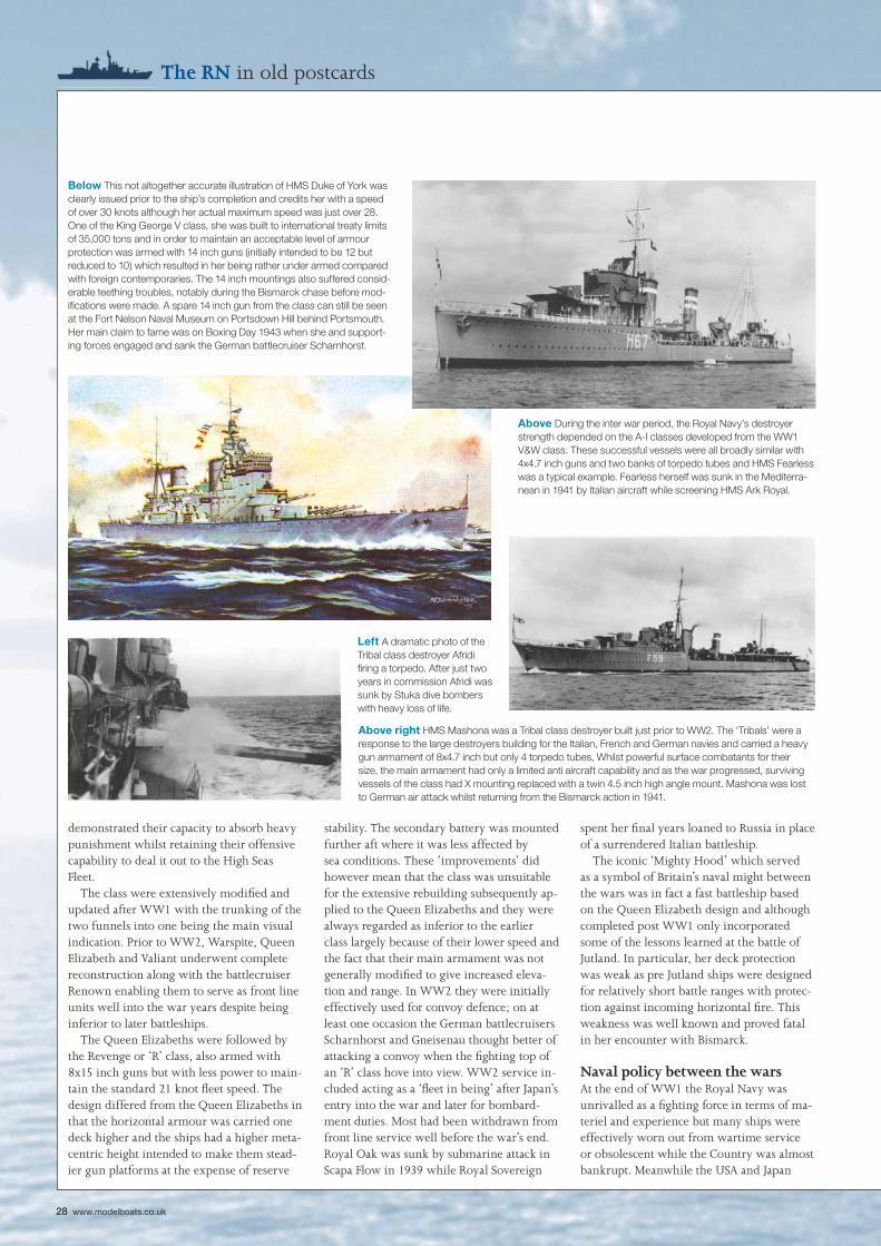
Below This not altogether accurate illustration of HMS Duke of York was clearly issued prior to the ship’s completion and credits her with a speed of over 30 knots although her actual maximum speed was just over 28. One of the King George V class, she was built to international treaty limits of 35,000 tons and in order to maintain an acceptable level of armour protection was armed with 14 inch guns (initially intended to be 12 but reduced to 10) which resulted in her being rather under armed compared with foreign contemporaries. The 14 inch mountings also suffered consid-erable teething troubles, notably during the Bismarck chase before mod-ifi cations were made. A spare 14 inch gun from the class can still be seen at the Fort Nelson Naval Museum on Portsdown Hill behind Portsmouth. Her main claim to fame was on Boxing Day 1943 when she and support-ing forces engaged and sank the German battlecruiser Scharnhorst.
Right HMS Lightning of 1941. The L class were a develop-ment of the J class with 6x4.7 inch guns in enclosed twin mountings with 50 degrees elevation. The after mount was fi tted to face forward with a blind arc astern. These ships were not built to retreat! A 4 inch high angle gun was fi tted in place of the after bank of torpedo tubes. Lightning was sunk in 1943 by a German MTB.
Model Boats Warships 29
guns which sacrifi ced gunpower in favour of protection and speed, much the same as the Germans had done in WW1. Their intended successors, the Lion class, would have been armed with 9x16 inch guns but were never completed although Britain’s last battleship, HMS Vanguard, completed post war, was es-sentially a Lion class but armed with 4x15 inch twin mountings taken from the WW1 light battlecruisers Glorious and Courageous before they were converted to aircraft carriers.
The major navies built up to the treaty lim-its for cruiser design which limited armament to 8 inch guns and 10,000 tons displacement and in the Royal Navy this resulted in the County Class which were good ships but rather larger than the RN really needed for commerce protection. By the early 1930s the RN had switched to smaller 6 inch gunned ships commencing with the Leander class which included Ajax and Achilles of River Plate fame. Both smaller and larger 6 inch cruisers were subsequently built, notably the excellent Southampton class with its fi nal development in HMS Edinburgh and HMS Belfast which were designed to resist 8 inch shellfi re.
Destroyers evolved steadily from the superb V & W classes at the end of WW1 through the A-I classes of the 1920s and 1930s and culminating in the Tribal and J-N classes and war built emergency classes of which HMS Cavalier is the only remaining example preserved at Chatham Dockyard.
The RN entered WW2 with a mixture of new, obsolescent and reconstructed warships, all of which gave sterling service throughout the war years and many of which were scrapped or put into reserve soon afterwards.
Today the Royal Navy, despite new ships such as the Daring class air defence destroyers and Astute class submarines is a shadow of its former self and whether the two new carriers presently building will effectively enter service remains in doubt. Meanwhile the World remains just as potentially dangerous as it always was and the country remains dependent upon keeping the sea lanes open for imports of vital food and materials just as it always has been but the lessons of history are frequently conveniently forgotten when budget restrictions begin to bite.
which were diminutives of the excellent G3 battlecruiser design and which were com-pleted as Nelson and Rodney and became the most powerful battleships in the world until the USS North Carolina and IJNS Yamato commissioned in 1941. The naval architects in all countries experimented with various methods of getting ‘the mostest for the leastest’ and in fi nding loopholes in the treaty restrictions such as the Royal Navy using ‘water armour’ in Nelson and Rodney. Japan attempted too much on the displacement of their cruiser size vessels and below to the point where they became unstable and had to be modifi ed which took them well over the treaty tonnage limits although this was not admitted at the time. Britain and the USA generally kept to the terms of the treaties but Germany, when she began rearming, paid little attention to the limits although claiming to do so. The RN’s ‘treaty’ battleships were the King George V class with their 10x14 inch
were busily engaged in building up their own navies with modern ships which included battleships armed with 16 inch guns. Great Britain had to respond and designs were drawn up for battlecruisers armed with 16 inch guns and battleships with 18 inch guns. All the signs were in place for another totally unaffordable naval race.
Realising that the strain on national fi nances would be too great, the politicians, at the instigation of America, entered into discussions to curb naval expenditure and the resulting Washington Naval Treaty set out relative strengths for the major navies of Great Britain, USA, Japan, France and Italy together with design limitations on major warship types with battleships being limited to 35,000 tons and 16 inch guns and ‘Treaty Cruisers’ to 10,000 tons and 8 inch guns. As many of the existing Royal Navy battleships were effectively obsolescent, Britain was allowed to build two 16 inch gun battleships
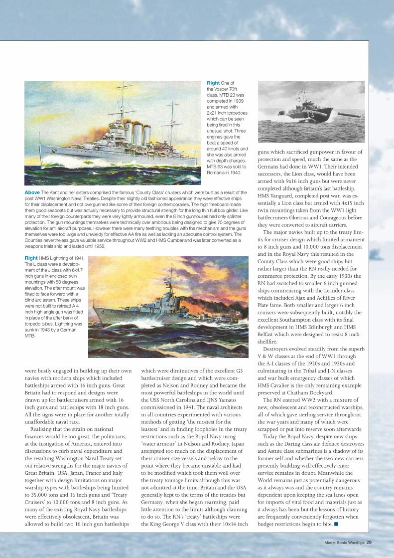
Above The Kent and her sisters comprised the famous ‘County Class’ cruisers which were built as a result of the post WW1 Washington Naval Treaties. Despite their slightly old fashioned appearance they were effective ships for their displacement and not overgunned like some of their foreign contemporaries. The high freeboard made them good seaboats but was actually necessary to provide structural strength for the long thin hull box girder. Like many of their foreign counterparts they were very lightly armoured, even the 8 inch gunhouses had only splinter protection. The gun mountings themselves were technically over ambitious being designed to give 70 degrees of elevation for anti aircraft purposes. However there were many teething troubles with the mechanism and the guns themselves were too large and unwieldy for effective AA fi re as well as lacking an adequate control system. The Counties nevertheless gave valuable service throughout WW2 and HMS Cumberland was later converted as a weapons trials ship and lasted until 1958.
Right One of the Vosper 70ft class, MTB 23 was completed in 1939 and armed with 2x21 inch torpedoes which can be seen being fi red in this unusual shot. Three engines gave the boat a speed of around 40 knots and she was also armed with depth charges. MTB 63 was sold to Romania in 1940.
■
30 www.modelboats.co.uk
1
HMS Daring
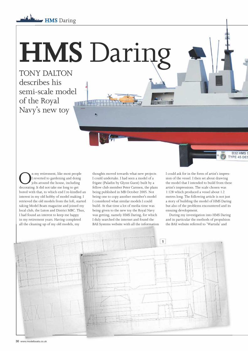
On my retirement, like most people I reverted to gardening and doing jobs around the house, including
decorating. It did not take me long to get bored with that, to which end I re-kindled an interest in my old hobby of model making. I retrieved the old models from the loft, started taking Model Boats magazine and joined my local club, the Luton and District MBC. Thus, I had found an interest to keep me happy in my retirement years. Having completed all the cleaning up of my old models, my
thoughts moved towards what new projects I could undertake. I had seen a model of a frigate (Paladin by Glynn Guest) built by a fellow club member Peter Carmen, the plans being published in MB October 2005. Not being one to copy another member’s model I considered what similar models I could build. At that time a lot of media time was being given to the new toy the Royal Navy was getting, namely HMS Daring, for which I duly searched the internet and found the BAE Systems website with all the information
I could ask for in the form of artist’s impres-sion of the vessel. I then set about drawing the model that I intended to build from these artist’s impressions. The scale chosen was 1:128 which produced a vessel about 1.2 metres long. The following article is not just a story of building the model of HMS Daring but also of the problems encountered and its ensuing development.
During my investigation into HMS Daring and in particular the methods of propulsion the BAE website referred to ‘Wartsila’ and
HMS DaringTONY DALTON describes his semi-scale modelof the RoyalNavy’s new toy
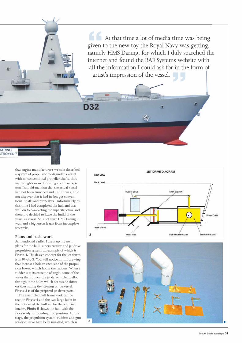
Model Boats Warships 31
2
3
that engine manufacturer’s website described a system of propulsion pods under a vessel with no conventional propeller shafts, thus my thoughts moved to using a jet drive sys-tem. I should mention that the actual vessel had not been launched and until it was, I did not discover that it had in fact got conven-tional shafts and propellers. Unfortunately by this time I had completed the hull and was well on to completing the superstructure and therefore decided to leave the build of the vessel as it was. So, a jet drive HMS Daring it was, and a big lesson learnt from incomplete research!
Plans and basic workAs mentioned earlier I drew up my own plans for the hull, superstructure and jet drive propulsion system, an example of which is Photo 1. The design concept for the jet drives is in Photo 2. You will notice in this drawing that there is a hole in each side of the propul-sion boxes, which house the rudders. When a rudder is at its extreme of angle, some of the water thrust from the jet drive is channelled through these holes which act as side thrust-ers thus aiding the steering of the vessel. Photo 3 is of the prepared jet drive parts.
The assembled hull framework can be seen in Photo 4 and the two large holes in the bottom of the hull are for the jet drive intakes. Photo 5 shows the hull with the sides ready for bonding into position. At this stage, the propulsion system, rudders and gun rotation servo have been installed, which is
“ At that time a lot of media time was being given to the new toy the Royal Navy was getting, namely HMS Daring, for which I duly searched the internet and found the BAE Systems website with all the information I could ask for in the form of artist’s impression of the vessel. ”
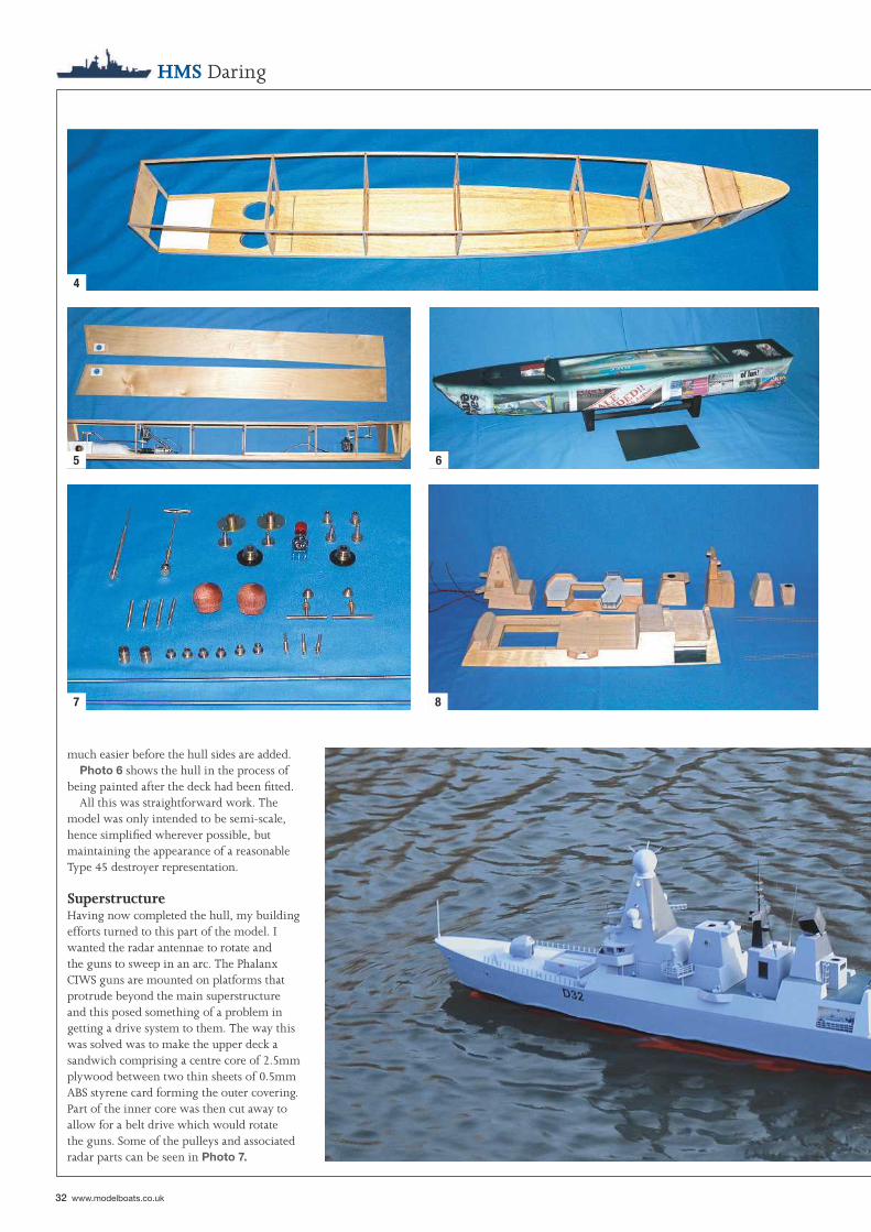
32 www.modelboats.co.uk
HMS Daring
much easier before the hull sides are added.Photo 6 shows the hull in the process of
being painted after the deck had been fi tted.All this was straightforward work. The
model was only intended to be semi-scale, hence simplifi ed wherever possible, but maintaining the appearance of a reasonable Type 45 destroyer representation.
SuperstructureHaving now completed the hull, my building efforts turned to this part of the model. I wanted the radar antennae to rotate and the guns to sweep in an arc. The Phalanx CIWS guns are mounted on platforms that protrude beyond the main superstructure and this posed something of a problem in getting a drive system to them. The way this was solved was to make the upper deck a sandwich comprising a centre core of 2.5mm plywood between two thin sheets of 0.5mm ABS styrene card forming the outer covering. Part of the inner core was then cut away to allow for a belt drive which would rotate the guns. Some of the pulleys and associated radar parts can be seen in Photo 7.
4
5 6
7 8
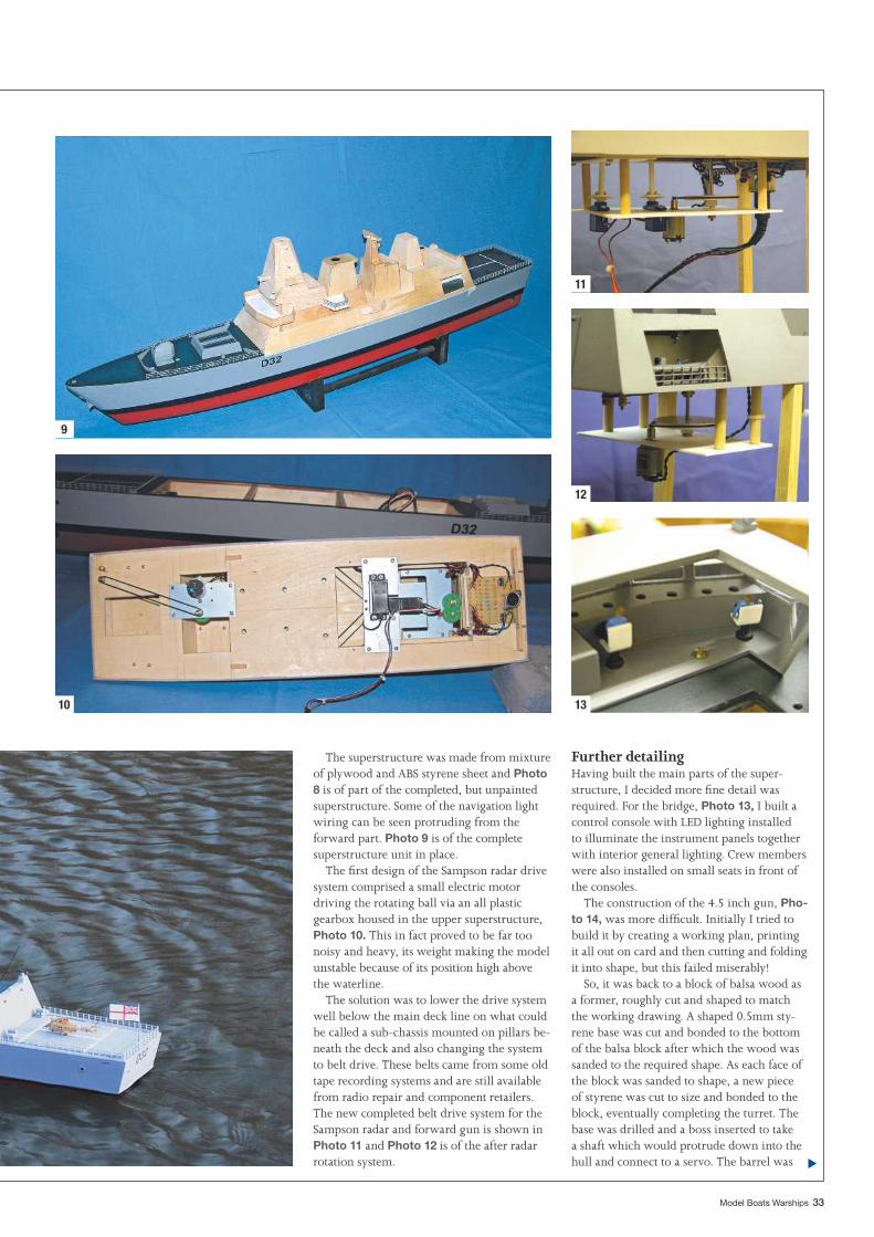
Model Boats Warships 33
The superstructure was made from mixture of plywood and ABS styrene sheet and Photo 8 is of part of the completed, but unpainted superstructure. Some of the navigation light wiring can be seen protruding from the forward part. Photo 9 is of the complete superstructure unit in place.
The fi rst design of the Sampson radar drive system comprised a small electric motor driving the rotating ball via an all plastic gearbox housed in the upper superstructure, Photo 10. This in fact proved to be far too noisy and heavy, its weight making the model unstable because of its position high above the waterline.
The solution was to lower the drive system well below the main deck line on what could be called a sub-chassis mounted on pillars be-neath the deck and also changing the system to belt drive. These belts came from some old tape recording systems and are still available from radio repair and component retailers. The new completed belt drive system for the Sampson radar and forward gun is shown in Photo 11 and Photo 12 is of the after radar rotation system.
Further detailingHaving built the main parts of the super-structure, I decided more fi ne detail was required. For the bridge, Photo 13, I built a control console with LED lighting installed to illuminate the instrument panels together with interior general lighting. Crew members were also installed on small seats in front of the consoles.
The construction of the 4.5 inch gun, Pho-to 14, was more diffi cult. Initially I tried to build it by creating a working plan, printing it all out on card and then cutting and folding it into shape, but this failed miserably!
So, it was back to a block of balsa wood as a former, roughly cut and shaped to match the working drawing. A shaped 0.5mm sty-rene base was cut and bonded to the bottom of the balsa block after which the wood was sanded to the required shape. As each face of the block was sanded to shape, a new piece of styrene was cut to size and bonded to the block, eventually completing the turret. The base was drilled and a boss inserted to take a shaft which would protrude down into the hull and connect to a servo. The barrel was
9
10
11
12
13
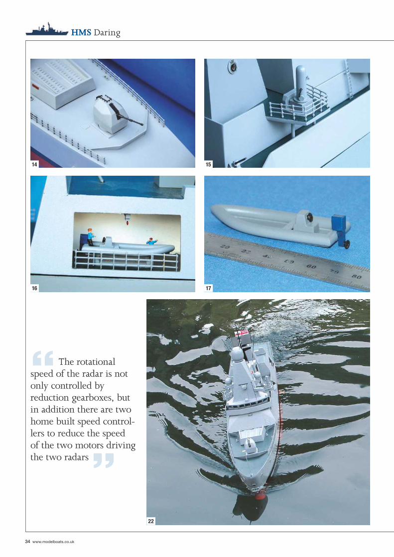
34 www.modelboats.co.uk
HMS Daring
14 15
16 17
22
“ The rotational speed of the radar is not only controlled by reduction gearboxes, but in addition there are two home built speed control-lers to reduce the speed of the two motors driving the two radars ”
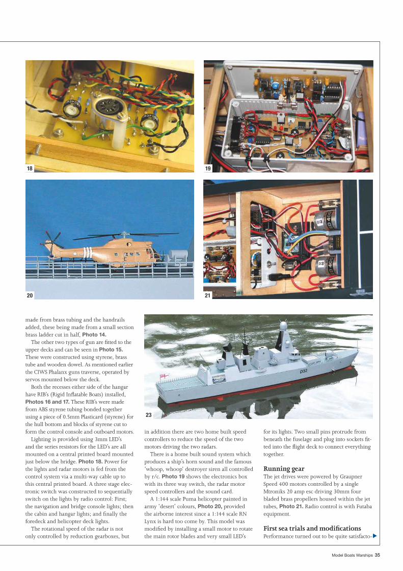
Model Boats Warships 35
for its lights. Two small pins protrude from beneath the fuselage and plug into sockets fi t-ted into the fl ight deck to connect everything together.
Running gearThe jet drives were powered by Graupner Speed 400 motors controlled by a single Mtroniks 20 amp esc driving 30mm four bladed brass propellers housed within the jet tubes, Photo 21. Radio control is with Futaba equipment.
First sea trials and modifi cationsPerformance turned out to be quite satisfacto-
in addition there are two home built speed controllers to reduce the speed of the two motors driving the two radars.
There is a home built sound system which produces a ship’s horn sound and the famous ‘whoop, whoop‘ destroyer siren all controlled by r/c. Photo 19 shows the electronics box with its three way switch, the radar motor speed controllers and the sound card.
A 1:144 scale Puma helicopter painted in army ‘desert’ colours, Photo 20, provided the airborne interest since a 1:144 scale RN Lynx is hard too come by. This model was modifi ed by installing a small motor to rotate the main rotor blades and very small LED’s
made from brass tubing and the handrails added, these being made from a small section brass ladder cut in half, Photo 14.
The other two types of gun are fi tted to the upper decks and can be seen in Photo 15. These were constructed using styrene, brass tube and wooden dowel. As mentioned earlier the CIWS Phalanx guns traverse, operated by servos mounted below the deck.
Both the recesses either side of the hangar have RIB’s (Rigid Infl atable Boats) installed, Photos 16 and 17. These RIB’s were made from ABS styrene tubing bonded together using a piece of 0.5mm Plasticard (styrene) for the hull bottom and blocks of styrene cut to form the control console and outboard motors.
Lighting is provided using 3mm LED’s and the series resistors for the LED’s are all mounted on a central printed board mounted just below the bridge. Photo 18. Power for the lights and radar motors is fed from the control system via a multi-way cable up to this central printed board. A three stage elec-tronic switch was constructed to sequentially switch on the lights by radio control: First; the navigation and bridge console lights; then the cabin and hangar lights; and fi nally the foredeck and helicopter deck lights.
The rotational speed of the radar is not only controlled by reduction gearboxes, but
18 19
20 21
23
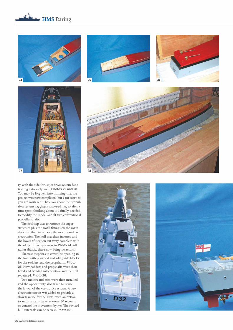
36 www.modelboats.co.uk
HMS Daring
ry with the side thrust jet drive system func-tioning extremely well, Photos 22 and 23. You may be forgiven into thinking that the project was now completed, but I am sorry as you are mistaken. The error about the propul-sion system naggingly annoyed me, so after a time spent thinking about it, I fi nally decided to modify the model and fi t two conventional propeller shafts.
The fi rst step was to remove the super-structure plus the small fi ttings on the main deck and then to remove the motors and r/c electronics. The hull was then inverted and the lower aft section cut away complete with the old jet drive system as in Photo 24. All rather drastic, there now being no return!
The next step was to cover the opening in the hull with plywood and add guide blocks for the rudders and the propshafts, Photo 25. New rudders and propshafts were then fi tted and bonded into position and the hull repainted. Photo 26.
Two motors and esc’s were then installed and the opportunity also taken to revise the layout of the electronics system. A new electronic circuit was added to provide a slow traverse for the guns, with an option to automatically traverse every 30 seconds or control the movement by r/c. The revised hull internals can be seen in Photo 27.
24 25 26
27 28
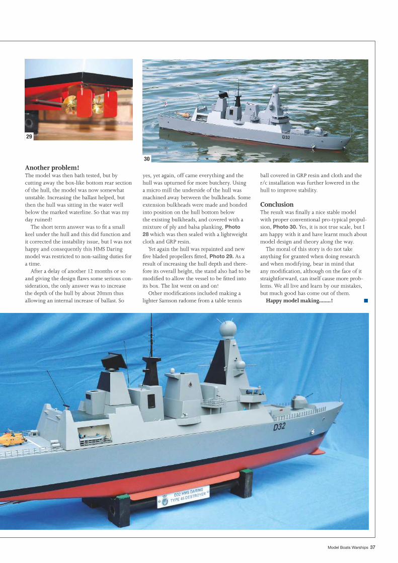
Model Boats Warships 37
Another problem!The model was then bath tested, but by cutting away the box-like bottom rear section of the hull, the model was now somewhat unstable. Increasing the ballast helped, but then the hull was sitting in the water well below the marked waterline. So that was my day ruined!
The short term answer was to fi t a small keel under the hull and this did function and it corrected the instability issue, but I was not happy and consequently this HMS Daring model was restricted to non-sailing duties for a time.
After a delay of another 12 months or so and giving the design fl aws some serious con-sideration, the only answer was to increase the depth of the hull by about 20mm thus allowing an internal increase of ballast. So
yes, yet again, off came everything and the hull was upturned for more butchery. Using a micro mill the underside of the hull was machined away between the bulkheads. Some extension bulkheads were made and bonded into position on the hull bottom below the existing bulkheads, and covered with a mixture of ply and balsa planking, Photo 28 which was then sealed with a lightweight cloth and GRP resin.
Yet again the hull was repainted and new fi ve bladed propellers fi tted, Photo 29. As a result of increasing the hull depth and there-fore its overall height, the stand also had to be modifi ed to allow the vessel to be fi tted into its box. The list went on and on!
Other modifi cations included making a lighter Samson radome from a table tennis
ball covered in GRP resin and cloth and the r/c installation was further lowered in the hull to improve stability.
ConclusionThe result was fi nally a nice stable model with proper conventional pro-typical propul-sion, Photo 30. Yes, it is not true scale, but I am happy with it and have learnt much about model design and theory along the way.
The moral of this story is do not take anything for granted when doing research and when modifying, bear in mind that any modifi cation, although on the face of it straightforward, can itself cause more prob-lems. We all live and learn by our mistakes, but much good has come out of them.
Happy model making........!
29
30
■
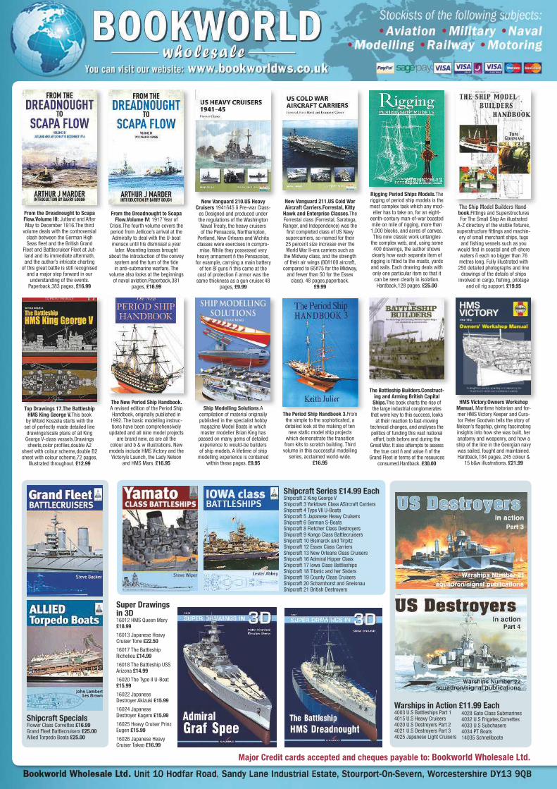
Major Credit cards accepted and cheques payable to: Bookworld Wholesale Ltd.
From the Dreadnought to Scapa Flow.Volume IV: 1917 Year of
Crisis.The fourth volume covers the period from Jellicoe’s arrival at the Admiralty to deal with the U-boat menace until his dismissal a year
later. Mounting losses brought about the introduction of the convoy
system and the turn of the tide in anti-submarine warfare. The
volume also looks at the beginnings of naval aviation.Paperback,381
pages, £16.99
F h D d h SFrom the Dreadnought to Scapa Flow.Volume III: Jutland and After May to December 1916.The third
volume deals with the controversial clash between the German High Seas fl eet and the British Grand
Fleet and Battlecruiser Fleet at Jut-land and its immediate aftermath, and the author’s intricate charting
of this great battle is still recognised and a major step forward in our
understanding of the events.Paperback,383 pages, £16.99
From the Dreadnought to Scapa
New Vanguard 210.US Heavy Cruisers 1941ñ45 ñ Pre-war Class-
es Designed and produced under the regulations of the Washington Naval Treaty, the heavy cruisers of the Pensacola, Northampton,
Portland, New Orleans and Wichita classes were exercises in compro-mise. While they possessed very
heavy armament ñ the Pensacolas, for example, carrying a main battery
of ten 8î guns ñ this came at the cost of protection ñ armor was the same thickness as a gun cruiser.48
pages, £9.99
N V d 210 US H New Vanguard 211.US Cold War Aircraft Carriers.Forrestal, Kitty
Hawk and Enterprise Classes.The Forrestal class (Forrestal, Saratoga, Ranger, and Independence) was the
fi rst completed class of US Navy supercarriers, so-named for their 25 percent size increase over the World War II-era carriers such as
the Midway class, and the strength of their air wings (80ñ100 aircraft,
compared to 65ñ75 for the Midway, and fewer than 50 for the Essex
class). 48 pages,paperback. £9.99
The Battleship Builders.Construct-ing and Arming British Capital
Ships.This book charts the rise of the large industrial conglomerates
that were key to this success, looks at their reaction to fast-moving
technical changes, and analyses the politics of funding this vast national effort, both before and during the
Great War. It also attempts to assess the true cost ñ and value ñ of the
Grand Fleet in terms of the resources consumed.Hardback. £30.00
HMS Victory.Owners Workshop Manual. Maritime historian and for-mer HMS Victory Keeper and Cura-tor Peter Goodwin tells the story of Nelson’s fl agship, giving fascinating insights into how she was built, her anatomy and weaponry, and how a ship of the line in the Georgian navy was sailed, fought and maintained. Hardback,184 pages, 245 colour &
15 b&w illustrations. £21.99
HMS Victory Owners Workshop
Rigging Period Ships Models.The rigging of period ship models is the most complex task which any mod-
eller has to take on, for an eight-eenth-century man-of-war boasted mile on mile of rigging, more than 1,000 blocks, and acres of canvas.This now classic work untangles
the complex web, and, using some 400 drawings, the author shows
clearly how each separate item of rigging is fi tted to the masts, yards and sails. Each drawing deals with only one particular item so that it can be seen clearly in isolation.Hardback,128 pages. £25.00
Rigging Period Ships Models The
The Ship Model Builders Hand-book.Fittings and Superstructures For The Small Ship An illustrated
A-Z directory of the visible fi xtures, superstructure fi ttings and machin-ery of small merchant ships, tugs and fi shing vessels such as you
would fi nd in coastal and off-shore waters ñ each no bigger than 76 metres long. Fully illustrated with 250 detailed photographs and line
drawings of the details of ships involved in cargo, fi shing, pilotage
and oil rig support. £19.95
The Ship Model Builders Hand-
The Period Ship Handbook 3.From the simple to the sophisticated, a detailed look at the making of ten
new static model ship projects which demonstrate the transition from kits to scratch building. Third
volume in this successful modelling series, acclaimed world-wide.
£16.95
The Period Ship Handbook 3 From
The New Period Ship Handbook. A revised edition of the Period Ship Handbook, originally published in
1992. The basic modelling instruc-tions have been comprehensively
updated and all nine model projects are brand new, as are all the
colour and b & w illustrations. New models include HMS Victory and the Victoryís Launch, the Lady Nelson
and HMS Mars. £16.95
Th N P i d Shi H db kShip Modelling Solutions.A
compilation of material originally published in the specialist hobby magazine Model Boats in which master modeller Brian King has
passed on many gems of detailed experience to would-be builders of ship models. A lifetime of ship
modelling experience is contained within these pages. £9.95
Ship Modelling Solutions ATop Drawings 17.The Battleship HMS King George V.This book
by Witold Koszela starts with the set of perfectly made detailed line drawings/scale plans of all King George V-class vessels.Drawings sheets,color profi les,double A2
sheet with colour scheme,double B2 sheet with colour scheme,72 pages,
Illustrated throughout. £12.99
Top Drawings 17 The Battleship
Shipcraft Series £14.99 EachShipcraft 2 King George VShipcraft 3 Yorktown Class ASircraft CarriersShipcraft 4 Type VII U-BoatsShipcraft 5 Japanese Heavy CruisersShipcraft 6 German S-BoatsShipcraft 8 Fletcher Class DestroyersShipcraft 9 Kongo Class BattlecruisersShipcraft 10 Bismarck and TirpitzShipcraft 12 Essex Class CarriersShipcraft 13 New Orleans Class CruisersShipcraft 16 Admiral Hipper ClassShipcraft 17 Iowa Class BattleshipsShipcraft 18 Titanic and her SistersShipcraft 19 County Class CruisersShipcraft 20 Scharnhorst and GneisnauShipcraft 21 British Destroyers
Shipcraft SpecialsFlower Class Corvettes £16.99Grand Fleet Battlecruisers £25.00Allied Torpedo Boats £25.00
Warships in Action £11.99 Each4003 U.S Battleships Part 14015 U.S Heavy Cruisers4020 U.S Destroyers Part 24021 U.S Destroyers Part 34025 Japanese Light Cruisers
Super Drawings in 3D16012 HMS Queen Mary £18.99
16013 Japanese Heavy Cruiser Tone £22.50
16017 The Battleship Richelieu £14.99
16018 The Battleship USS Arizona £14.99
16020 The Type II U-Boat £15.99
16022 Japanese Destroyer Akizuki £15.99
16024 Japanese Destroyer Kagero £15.99
16025 Heavy Cruiser Prinz Eugen £15.99
16026 Japanese Heavy Cruiser Takao £16.99
4028 Gato Class Submarines4032 U.S Frigates,Corvettes 4033 U.S Subchasers4034 PT Boats14035 Schnellboote
UK Postage: single book £2.50, two or more books £4.50. Overseas Airmail: please allow 15% of order value.
Bookworld Wholesale are pleasedto announce that they are NOW stockists of
Sabingamartin Publications
Images of War.Battleships: The First Big Guns.This new addition to the Images of War series takes
as its focus the early Big Gun battleships that saw development and deployment during the First World War. Iconic ships such as
HMS Warspite and Malaya feature amidst this pictorial history that is sure to appeal to fans of the series, and naval enthusiasts in particular.Paperback,144 pages.
£14.99
Images of War Battleships: The
Battleships of the Bismarck Class. Detailed description of the ships, with full technical details, and an outline of their service,
heavily illustrated with plans, battle maps and a substantial collection of photographs. These have been out of print for ten years or more and are now much sought after by enthusiasts and collectors, so this new modestly priced
reprint of the series will be widely welcomed.160 pages,paperback.
£16.99
Battleships of the BismarckBattleships of the Scharnhorst. Detailed description of the ships, with full technical details, and an outline of their service, heavily
illustrated with plans, battle maps and a substantial collection of photographs. These have been
out of print for ten years or more and are now much sought after by enthusiasts and collectors, so this new modestly priced
reprint of the series will be widely welcomed.176 pages,paperback.
£16.99
Battleships of the Scharnhorst Pocket Battleships of the Deutschland Class. Detailed
description of the ships, with full technical details, and an outline of
their service, heavily illustrated with plans, battle maps and a substantial
collection of photographs. These have been out of print for ten years or more and are now much sought after by enthusiasts and collectors,
so this new modestly priced reprint of the series will be widely welcomed.224 pages,paperback.
£16.99
Pocket Battleships of the
Images of War.U-boat Prey: Mer-chant Sailors at War, 1939-1942.Over 30,000 men fell victim to the
German U-boats between 1939 and 1945. This publication serves
as a tribute to their efforts, and will be followed by a second volume
covering the fi nal stages of the war, from 1943-45. Images of some of the most imposing merchant ships
feature, accompanied by a lucid narrative describing the various roles enacted by the sailors on
board and the wartime context in which they worked.Paperback,128
pages. £14.99
Images of War U boat Prey: Mer New Vanguard 204.British Battleships 1914ñ18 (2)The
Super Dreadnoughts.In 1906, the Germans began building their own dreadnought fl eet armed with larger guns, word of which soon
reached the British Admiralty. This raised the spectre that the British dreadnought fl eet would be out-
gunned, and prompted the Admiral-ty to order the building of their own ìsuper dreadnoughtsî. The fi rst of
these new dreadnoughts were laid down in 1909, and entered service
three years later. Paperback,48 pages. £9.99
New Vanguard 204 British
Ship Dioramas. Bringing Your Models to Life.This book is about
the art of displaying waterline models. By their very nature, ship models that do not show the full hull and are not mounted on an artificial stand cry out for a real-istic setting. At its most basic this can be just a representation of the sea itself, but to give the model a context ñ even to tell some sort
of story ñ is far more challenging. This is the province of the diora-ma, which at its most effective is a depiction of a scene or an event
in which the ship model takes centre stage.Hardback.
£25.00
Ship Dioramas Bringing YourShip Models from Kits. Basic and
Advanced Techniques for Small Scales.In the past thirty years the
world of model kits has undergone a veritable revolution. New tech-niques in injection moulding have improved the scale accuracy and
surface detail of the humble plastic kit, while many specialist compa-nies now produce top-quality resin
models, vastly broadening the range of subjects on the market. However, the really radical change has been the advent of photo-etched brass fret, which allows the fi nest detail to be reproduced to scale.Paper-
back,140 pages. £14.99
Ship Models from Kits Basic and
Warships and Warship Modelling.This is a book which will appeal equally to naval enthusiasts and
ship modellers. It offers an overview of the design, development and classifi cation of modern warship
types and it studies the constructorsí original models, explaining why and how they were made. The book then turns to scale modelling with detailed
chapters on choosing a subject, a scale, methods of construction, ma-
terials and techniques and the details of fi ttings and painting. £19.95
Warships and Warship ModellingThe Anatomy of Nelsonís Ships.The naval archives containing re-
cords of Horatio Nelsonís ships were researched in detail by Dr. Longridge to produce this classic book. His ex-
pert text is supported by 271 detailed line drawings, rare photographs
and unique fold-out plans showing hull framing, interior construction, complex rigging and deck layouts. Anyone interested in ships, naval architecture or ship modelling will fi nd this book invaluable. £40.00
The Anatomy of Nelsonís Ships
Japanese Heavy Cruiser Takao, 1937-1946 in 3D.With
ground-breaking 3D imagery, each corner, angle, and dimension of the ship is viewable. With various close-up views, and each 3D image based on actual technical scale drawings and photographs, this makes an
exceptional reference tool.Takao was the fi rst of four Takao-
class heavy cruisers designed to be an improvement over the previous Myoko-class design. The Myoko had proved to be unstable and
required modifi cations, which were incorporated into the Takao design.
£15.99
Japanese Heavy Cruiser Top Drawings 18.The Battleship HMS Warspite. Includes drawing sheets, colour profi les, double A2 sheet with colour scheme, double B2 sheet with colour scheme.The latest in the Topdrawings series.
HMS Warspite is in the “Queen Eliz-abeth Class” or a superdreadnought
as they became known.She saw action at Jutland and continued her career through the Second World
War in action at D day before being scrapped in 1948. She earned the most battle honours ever awarded
to an indiviual ship in the Royal Navy and the most awarded for
actions during World War II. £15.99
Top Drawings 18 The Battleship
WP 4 USS Texas BB-35WP 10 Indianapolis & PortlandWP 23 Italian Heavy CruisersWP 24 Arleigh Burke WP 30 IJN TakaoWP 31 USS BuchananWP 32 South DakotaWP 33 USS Lexington CV-2WP 34 USN Battleships in ColourWP 35 Ticonderoga ClassWP 36 Kriegsmarine ScharnhorstWP 37 RM RomaWP 38 IJN NagatoWP 39 German Battleships 39-45WP 40 USS Independance CVL-22WP 41 US Midway CV-41
On Deck Warship Walkaround £15.99 Each5601 USS Alabama5602 USS Lexington5603 Ohio-Class SSBN5604 USS Pampanito5605 Elco 80 PT Boat5606 Nimitz Class Carriers5607 Iowa Class Battleships26008 Higgins PT Boat £16.9926010 USS Kidd £11.9926011 USS Massachusets £11.99
Warship Pictorial £14.99 Each
Realistic Wood Effects.First book of this new collection.The collection is oriented to help modelers through different modeling tasks.This volume is dedicated to paint different types of wood, planes,ships , tools, accessories etc.Becasuse of its low price it will be a great help for all modelers and a stand out collection.Published by AK Interactive £10.99
The Weathering Magazine 7.In-side, the theme of snow and ice is covered in depth with all of the techniques needed to set our models in a winter environment with plenty of Ice and Snow. From how to make a spectacular frozen diorama to adding subtle snow effects on a T34. Furthermore, this issue has 16 additional pages to learn and enjoy even more. As always, these techniques will be explained by the best modelers in the world.£8.99
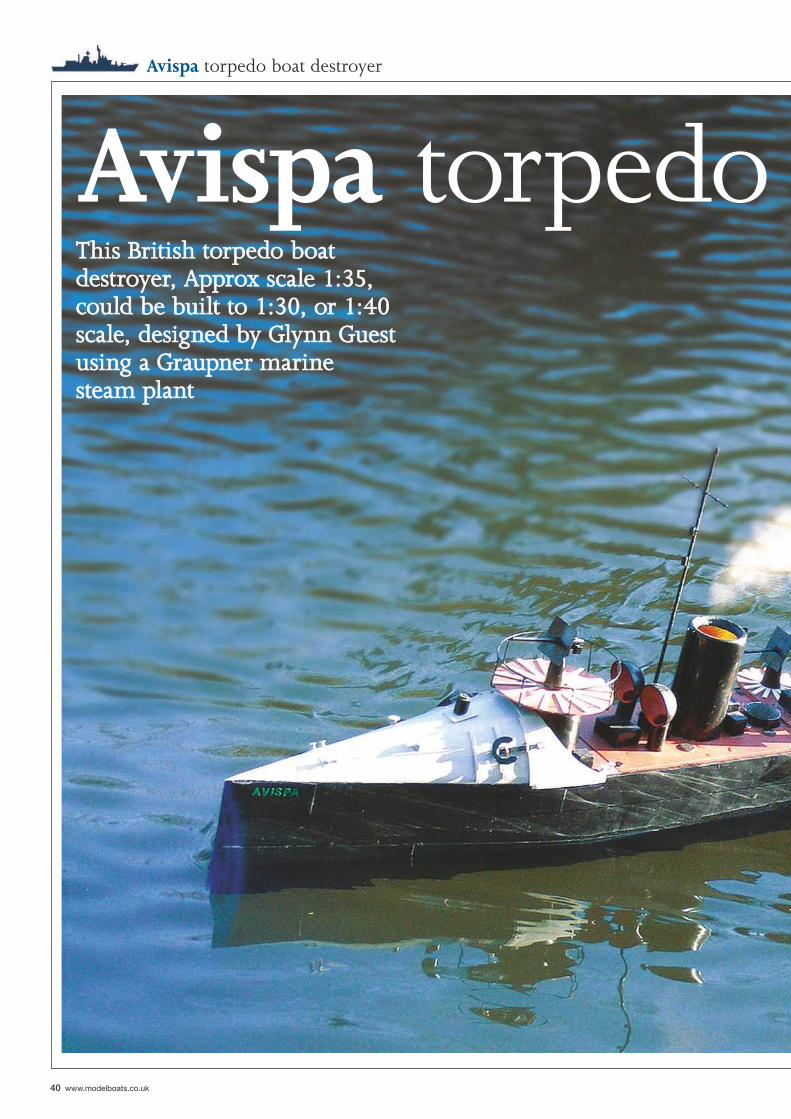
40 www.modelboats.co.uk
Avispa torpedo boat destroyer
Avispa torpedo This British torpedo boat This British torpedo boat destroyer, Approx scale 1:35, destroyer, Approx scale 1:35, could be built to 1:30, or 1:40 could be built to 1:30, or 1:40 scale, designed by Glynn Guest scale, designed by Glynn Guest using a Graupner marine using a Graupner marine steam plantsteam plant
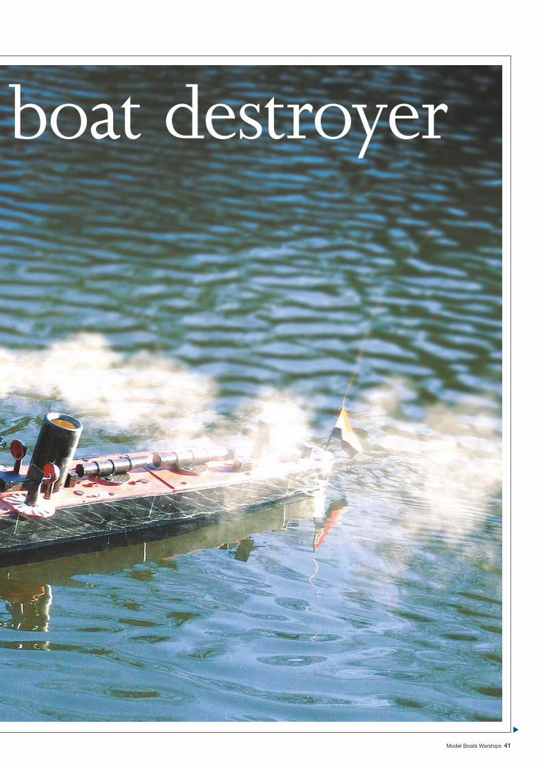
Model Boats Warships 41
boat destroyer
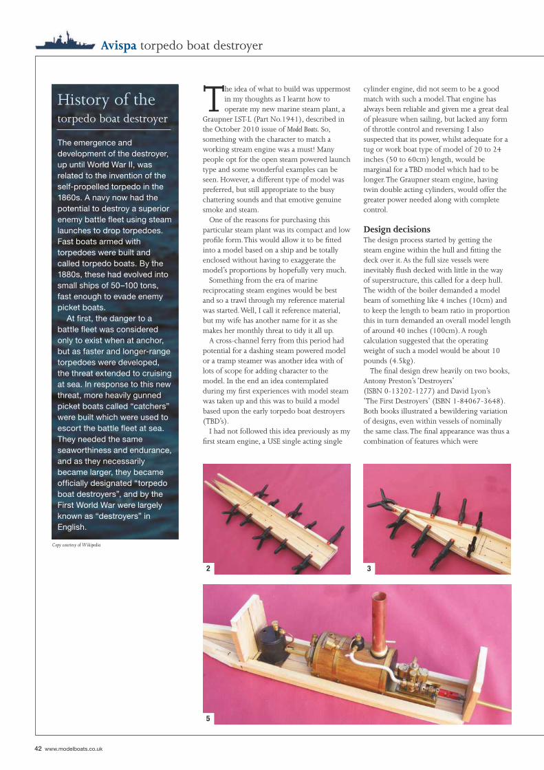
42 www.modelboats.co.uk
History of the torpedo boat destroyer
Avispa torpedo boat destroyer
The idea of what to build was uppermost in my thoughts as I learnt how to operate my new marine steam plant, a
Graupner LST-L (Part No.1941), described in the October 2010 issue of Model Boats. So, something with the character to match a working stream engine was a must! Many people opt for the open steam powered launch type and some wonderful examples can be seen. However, a different type of model was preferred, but still appropriate to the busy chattering sounds and that emotive genuine smoke and steam.
One of the reasons for purchasing this particular steam plant was its compact and low profi le form. This would allow it to be fi tted into a model based on a ship and be totally enclosed without having to exaggerate the model’s proportions by hopefully very much.
Something from the era of marine reciprocating steam engines would be best and so a trawl through my reference material was started. Well, I call it reference material, but my wife has another name for it as she makes her monthly threat to tidy it all up.
A cross-channel ferry from this period had potential for a dashing steam powered model or a tramp steamer was another idea with of lots of scope for adding character to the model. In the end an idea contemplated during my fi rst experiences with model steam was taken up and this was to build a model based upon the early torpedo boat destroyers (TBD’s).
I had not followed this idea previously as my fi rst steam engine, a USE single acting single
cylinder engine, did not seem to be a good match with such a model. That engine has always been reliable and given me a great deal of pleasure when sailing, but lacked any form of throttle control and reversing. I also suspected that its power, whilst adequate for a tug or work boat type of model of 20 to 24 inches (50 to 60cm) length, would be marginal for a TBD model which had to be longer. The Graupner steam engine, having twin double acting cylinders, would offer the greater power needed along with complete control.
Design decisionsThe design process started by getting the steam engine within the hull and fi tting the deck over it. As the full size vessels were inevitably fl ush decked with little in the way of superstructure, this called for a deep hull. The width of the boiler demanded a model beam of something like 4 inches (10cm) and to keep the length to beam ratio in proportion this in turn demanded an overall model length of around 40 inches (100cm). A rough calculation suggested that the operating weight of such a model would be about 10 pounds (4.5kg).
The fi nal design drew heavily on two books, Antony Preston’s ‘Destroyers’ (ISBN 0-13202-1277) and David Lyon’s ‘The First Destroyers’ (ISBN 1-84067-3648). Both books illustrated a bewildering variation of designs, even within vessels of nominally the same class. The fi nal appearance was thus a combination of features which were
The emergence and development of the destroyer, up until World War II, was related to the invention of the self-propelled torpedo in the 1860s. A navy now had the potential to destroy a superior enemy battle fl eet using steam launches to drop torpedoes. Fast boats armed with torpedoes were built and called torpedo boats. By the 1880s, these had evolved into small ships of 50–100 tons, fast enough to evade enemy picket boats. At fi rst, the danger to a battle fl eet was considered only to exist when at anchor, but as faster and longer-range torpedoes were developed, the threat extended to cruising at sea. In response to this new threat, more heavily gunned picket boats called “catchers” were built which were used to escort the battle fl eet at sea. They needed the same seaworthiness and endurance, and as they necessarily became larger, they became offi cially designated “torpedo boat destroyers”, and by the First World War were largely known as “destroyers” in English.
2 3
5
Copy courtesy of Wikipedia
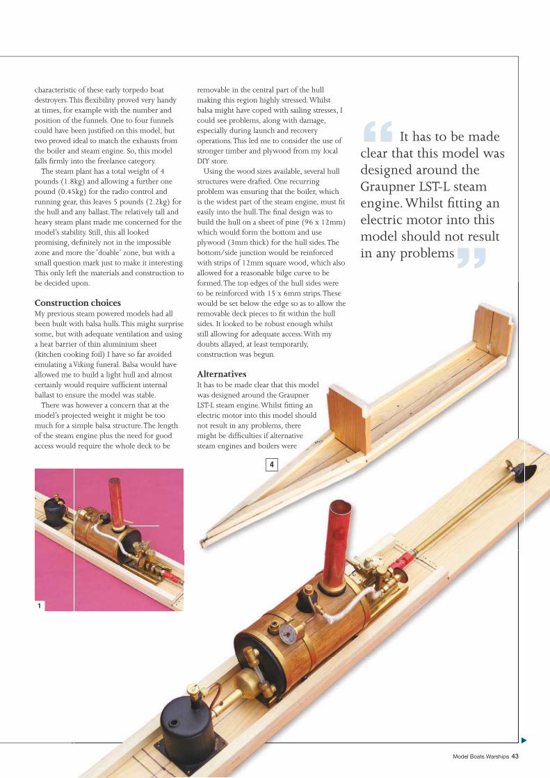
Model Boats Warships 43
characteristic of these early torpedo boat destroyers. This fl exibility proved very handy at times, for example with the number and position of the funnels. One to four funnels could have been justifi ed on this model, but two proved ideal to match the exhausts from the boiler and steam engine. So, this model falls fi rmly into the freelance category.
The steam plant has a total weight of 4 pounds (1.8kg) and allowing a further one pound (0.45kg) for the radio control and running gear, this leaves 5 pounds (2.2kg) for the hull and any ballast. The relatively tall and heavy steam plant made me concerned for the model’s stability. Still, this all looked promising, defi nitely not in the impossible zone and more the ‘doable’ zone, but with a small question mark just to make it interesting. This only left the materials and construction to be decided upon.
Construction choicesMy previous steam powered models had all been built with balsa hulls. This might surprise some, but with adequate ventilation and using a heat barrier of thin aluminium sheet (kitchen cooking foil) I have so far avoided emulating a Viking funeral. Balsa would have allowed me to build a light hull and almost certainly would require suffi cient internal ballast to ensure the model was stable.
There was however a concern that at the model’s projected weight it might be too much for a simple balsa structure. The length of the steam engine plus the need for good access would require the whole deck to be
removable in the central part of the hull making this region highly stressed. Whilst balsa might have coped with sailing stresses, I could see problems, along with damage, especially during launch and recovery operations. This led me to consider the use of stronger timber and plywood from my local DIY store.
Using the wood sizes available, several hull structures were drafted. One recurring problem was ensuring that the boiler, which is the widest part of the steam engine, must fi t easily into the hull. The fi nal design was to build the hull on a sheet of pine (96 x 12mm) which would form the bottom and use plywood (3mm thick) for the hull sides. The bottom/side junction would be reinforced with strips of 12mm square wood, which also allowed for a reasonable bilge curve to be formed. The top edges of the hull sides were to be reinforced with 15 x 6mm strips. These would be set below the edge so as to allow the removable deck pieces to fi t within the hull sides. It looked to be robust enough whilst still allowing for adequate access. With my doubts allayed, at least temporarily, construction was begun.
AlternativesIt has to be made clear that this model was designed around the Graupner LST-L steam engine. Whilst fi tting an electric motor into this model should not result in any problems, there might be diffi culties if alternative steam engines and boilers were
“ It has to be made clear that this model was designed around the Graupner LST-L steam engine. Whilst fi tting an electric motor into this model should not result in any problems”
md
pengine plus the need for g
Model Boats Warships 43
engine plus the need for gd require the whole deck to
1
ad all surprise d using
ided d have most nal
theoo length
formed. The top edges of the hull sides were to be reinforced with 15 x 6mm strips. Thesewould be set below the edge so as to allow the
w
ggoodgood o be
would be set below the edge so as to allow the removable deck pieces to fi t within the hull sides. It looked to be robust enough whilst still allowing for adequate access. With my doubts allayed, at least temporarily,construction was begun.
AlternativesIt has to be made clear that this model was designed around the GraupnerLST-L steam engine. Whilst fi tting an electric motor into this model should not result in any problems, there y pmight be difficulties if alternativemight be diffi culties if alternative steam engines and boilers were
4
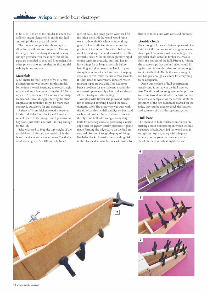
44 www.modelboats.co.uk
Avispa torpedo boat destroyer
to be used. It is up to the builder to check that different steam plants will fi t inside this hull and still produce a practical model.
The model’s design is simple enough to allow for modifi cations if required. Altering the length, beam or draught should be easy enough provided you make sure that all the parts are modifi ed so they still fi t together. The other proviso is to ensure that the fi nal model stability is not impaired.
MaterialsA 2.4 metre (8 foot) length of 96 x 12mm planned timber was bought for this model. Some time is worth spending to select straight, square and knot free wood. Lengths of 12mm square, 15 x 6mm and 12 x 6mm wood strip are needed. I would suggest buying the same lengths as the timber; it might be more than you need, but allows for any mistakes.
A sheet of 3mm thick plywood is required for the hull sides. I was lucky and found a suitable piece in the garage, but if you have to buy some just make sure that it is long enough for the job.
Balsa was used to keep the top weight of the model down. It formed the turtleback in the bows, the decks and rounded stern. The decks needed a length of 5 x 100mm (3/16 x 4
inches) balsa, but scrap pieces were used for the other items. All the wood-wood joints were made with PVA white woodworking glue. It allows suffi cient time to adjust the position of the items to be joined before they must be held together and allowed to dry. This normally takes 24 hours although more rapid setting types are available, but I still like to leave things for as long as possible before handling any glued structure. The fi nal glue strength, absence of smell and ease of wiping away any excess, make the use of PVA sensible. It is not rated as waterproof, although water-resistant types are available. This has never been a problem for me since my models do not remain permanently afl oat and are always allowed to dry out after sailing.
Working with timber and plywood ought not to demand anything beyond the usual domestic tools. The prototype was built with the aid of an electric drill and jigsaw, but hand tools would suffi ce. In fact I chose to cut out the plywood hull sides using a heavy duty knife for accuracy and also producing a neater edge than the jigsaw usually produces. A plane made forming the bilge curve on the hull an easy task. For quick rough shaping of things like balsa blocks, I usually use a sanding disk in the electric drill which is one of those jobs
that need to be done with care, and outdoors!
Double checkEven though all the calculations appeared okay, I still took the precaution of laying the whole steam plant connected with a coupling to the propeller shaft, onto the timber that was to form the bottom of the hull, Photo 1. Adding the square strips that the hull sides would fi t against, and it was clear that everything ought to fi t into the hull. The boiler was a snug fi t, but had just enough clearance for everything to be acceptable.
Using this method of hull construction I usually fi nd it best to cut the hull sides out fi rst. The dimensions are given on the plan and to ensure two identical sides, the fi rst one can be used as a template for the second. With the positions of the two bulkheads marked on the sides, they can be used to check the location and accuracy of parts during construction.
Hull baseThe method of hull construction centres on making a stout hull base upon which the hull structure is built. Provided the wood used is straight and square, along with adequate accuracy in the parts you cut out (which should be easy as only straight cuts are
7
6
8
9
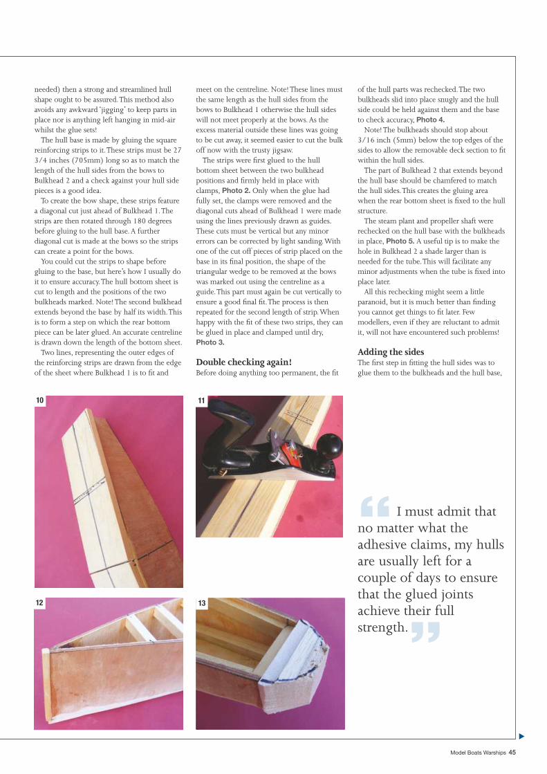
Model Boats Warships 45
needed) then a strong and streamlined hull shape ought to be assured. This method also avoids any awkward ‘jigging’ to keep parts in place nor is anything left hanging in mid-air whilst the glue sets!
The hull base is made by gluing the square reinforcing strips to it. These strips must be 27 3/4 inches (705mm) long so as to match the length of the hull sides from the bows to Bulkhead 2 and a check against your hull side pieces is a good idea.
To create the bow shape, these strips feature a diagonal cut just ahead of Bulkhead 1. The strips are then rotated through 180 degrees before gluing to the hull base. A further diagonal cut is made at the bows so the strips can create a point for the bows.
You could cut the strips to shape before gluing to the base, but here’s how I usually do it to ensure accuracy. The hull bottom sheet is cut to length and the positions of the two bulkheads marked. Note! The second bulkhead extends beyond the base by half its width. This is to form a step on which the rear bottom piece can be later glued. An accurate centreline is drawn down the length of the bottom sheet.
Two lines, representing the outer edges of the reinforcing strips are drawn from the edge of the sheet where Bulkhead 1 is to fi t and
meet on the centreline. Note! These lines must the same length as the hull sides from the bows to Bulkhead 1 otherwise the hull sides will not meet properly at the bows. As the excess material outside these lines was going to be cut away, it seemed easier to cut the bulk off now with the trusty jigsaw.
The strips were fi rst glued to the hull bottom sheet between the two bulkhead positions and fi rmly held in place with clamps, Photo 2. Only when the glue had fully set, the clamps were removed and the diagonal cuts ahead of Bulkhead 1 were made using the lines previously drawn as guides. These cuts must be vertical but any minor errors can be corrected by light sanding. With one of the cut off pieces of strip placed on the base in its fi nal position, the shape of the triangular wedge to be removed at the bows was marked out using the centreline as a guide. This part must again be cut vertically to ensure a good fi nal fi t. The process is then repeated for the second length of strip. When happy with the fi t of these two strips, they can be glued in place and clamped until dry, Photo 3.
Double checking again!Before doing anything too permanent, the fi t
of the hull parts was rechecked. The two bulkheads slid into place snugly and the hull side could be held against them and the base to check accuracy, Photo 4.
Note! The bulkheads should stop about 3/16 inch (5mm) below the top edges of the sides to allow the removable deck section to fi t within the hull sides.
The part of Bulkhead 2 that extends beyond the hull base should be chamfered to match the hull sides. This creates the gluing area when the rear bottom sheet is fi xed to the hull structure.
The steam plant and propeller shaft were rechecked on the hull base with the bulkheads in place, Photo 5. A useful tip is to make the hole in Bulkhead 2 a shade larger than is needed for the tube. This will facilitate any minor adjustments when the tube is fi xed into place later.
All this rechecking might seem a little paranoid, but it is much better than fi nding you cannot get things to fi t later. Few modellers, even if they are reluctant to admit it, will not have encountered such problems!
Adding the sidesThe fi rst step in fi tting the hull sides was to glue them to the bulkheads and the hull base,
“ I must admit that no matter what the adhesive claims, my hulls are usually left for a couple of days to ensure that the glued joints achieve their full strength.”
1110
1312
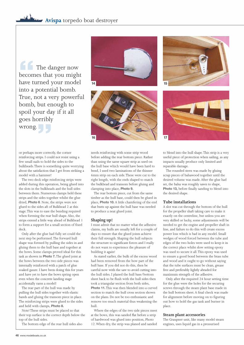
46 www.modelboats.co.uk
Avispa torpedo boat destroyer
or perhaps more correctly, the corner reinforcing strips. I could not resist using a few small nails to hold the sides to the bulkheads. There is something quite worrying about the satisfaction that I get from striking a model with a hammer!
The two deck edge reinforcing strips were added during this operation, being glued into the slots in the bulkheads and the hull sides between them. Numerous clamps held these strips and the sides together whilst the glue dried, Photo 6. Note, the strips were not glued to the sides aft of Bulkhead 2 at this stage. This was to ease the bending required when forming the rear hull shape. Also, the strips extend a little way ahead of Bulkhead 1 to form a support for a small section of fi xed deck.
Only after the glue had fully set could the next step be performed. The forward hull shape was formed by pulling the sides in and gluing them to the hull base and together at the bows. Some clamps proved ideal for this task as shown in Photo 7. The glued joint at the bows between the two side pieces was internally reinforced with a patch of glue soaked gauze. I have been doing this for years and have yet to have the bows spring open even when the concrete landing stage accidentally rams a model!
The rear part of the hull was made by pulling the hull sides together with elastic bands and gluing the transom piece in place. The reinforcing strips were glued to the sides and held with clamps, Photo 8.
Note! These strips must be placed so that their top surface is the correct depth below the top of the hull sides.
The bottom edge of the rear hull sides also
needs reinforcing with some strip wood before adding the rear bottom piece. Rather than using the same square strip as used on the hull base which would have been hard to bend, I used two laminations of the thinner 6mm strip on each side. These were cut to the right length, with the ends shaped to match the bulkhead and transom before gluing and clamping into place, Photo 9.
The rear bottom piece, cut from the same timber as the hull base, could then be glued in place, Photo 10. A little chamfering of the end that butts up against the hull base was needed to produce a neat glued joint.
Shaping up!I must admit that no matter what the adhesive claims, my hulls are usually left for a couple of days to ensure that the glued joints achieve their full strength. Shaping the hull subjects the structure to signifi cant forces and I really do not want to experience the pleasure of building it again!
As stated earlier, the bulk of the excess wood had been removed from the bow part of the hull base. If you did not do this, then be careful now with the saw to avoid cutting into the hull sides. I planed the hull base/bottom sheet back to be fl ush with the hull sides then took a triangular section from both sides, Photo 11. This was then blended into a curved section to match the hull cross section shown on the plans. Do not be too enthusiastic and remove too much material thus weakening the hull.
Where the edges of the two side pieces meet at the bows, this was sanded fl at before a strip of hardwood was glued into position, Photo 12. When dry, the strip was planed and sanded
to blend into the hull shape. This strip is a very useful piece of protection when sailing, as any impacts usually produce only limited and reparable damage.
The rounded stern was made by gluing scrap pieces of balsawood together until the desired volume was made. After the glue had set, the balsa was roughly sawn to shape, Photo 13, before fi nally sanding to blend into the desired shape.
Tube installationsA slot was cut through the bottom of the hull for the propeller shaft taking care to make it exactly on the centreline, but unless you are very skilled or lucky, some adjustments will be needed to get the engine and propeller shaft in line, and failure to do this will create excess power loss which is bad in any model. Small wedges of wood forced between the tube and edges of the two holes were used to keep it in the correct place whilst slow setting epoxy was used to secure it all. This epoxy was used to ensure a good bond between the brass tube and wood and it ought to go without saying that the tube surfaces must be clean, grease free and preferably lightly abraded for maximum strength of the adhesive.
Only after the required 24 hour setting time for the glue were the holes for the securing screws through the steam plant base made in the hull bottom sheet. A fi nal check was made for alignment before moving on to fi guring out how to hold the gas tank and burner in place.
Steam plant accessoriesThe Graupner unit, like many model steam engines, uses liquid gas in a pressurised
“ The danger now becomes that you might have turned your model into a potential bomb. True, not a very powerful bomb, but enough to spoil your day if it all goes horribly wrong.”
14 15
16 17
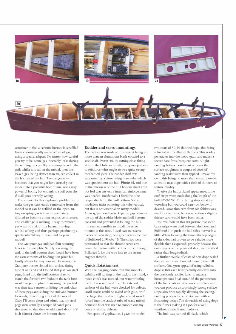
Model Boats Warships 47
container to fuel a ceramic burner. It is refi lled from a commercially available can of gas, using a special adapter. No matter how careful you try to be, some gas inevitably leaks during the refi lling process. If you attempt to refi ll the tank whilst it is still in the model, then the leaked gas, being denser than air, can collect in the bottom of the hull. The danger now becomes that you might have turned your model into a potential bomb. True, not a very powerful bomb, but enough to spoil your day if it all goes horribly wrong.
The answer to this explosive problem is to make the gas tank easily removable from the model so it can be refi lled in the open air. Any escaping gas is thus immediately diluted to become a non-explosive mixture. The challenge is making it easy to remove, yet with no risk of the burner moving whilst sailing and thus perhaps producing a spectacular Viking funeral end to your model!
The Graupner gas tank had four securing holes in its base plate. Simply screwing the tank to the hull bottom sheet would have been the easiest means of holding it in place but hardly allows for easy removal. However, the Graupner burner slotted into a close fi tting tube at one end and I found that just two steel pegs, fi tted into the hull bottom sheet to match the forward two holes in the tank base, would keep it in place. Removing the gas tank was then just a matter of lifting the tank clear of these pegs and sliding the tank and burner forwards, then lifting it out of the model. Okay, I’ll come clean and admit that my steel pegs were actually a couple of panel pins shortened so that they would stand about 1/8 inch (3mm) above the bottom sheet.
Rudder and servo mountingsThe rudder was made at this time, it being no more than an aluminium blade epoxied to a steel shaft, Photo 14. By cutting close fi tting slots in the blade and shaft, the epoxy just acts to reinforce what ought to be a quite strong mechanical joint. The rudder shaft was supported by a close fi tting brass tube which was epoxied into the hull, Photo 15. and due to the thickness of the hull bottom sheet I did not feel that any extra internal reinforcement was needed. Incidentally I fi xed the tube perpendicular to the hull bottom. Some modellers insist on fi tting this tube vertical, but this is not essential on many models. Anyway, ‘perpendicular’ kept the gap between the top of the rudder blade and hull bottom constant and prevented it fouling the hull.
It seemed sensible to install the servo mounts at this time. I used two transverse pieces of balsa strip, one glued across the rear of Bulkhead 2, Photo 16. The strips were positioned so that the throttle servo arm would be in-line with the hole drilled though Bulkhead 2 for the wire link to the steam engines throttle.
Quick fl otation testWith the nagging doubt over this model’s stability still lurking in the back of my mind, a quick check was needed, but waterproofi ng the hull was required fi rst. The external surfaces of the hull were checked for defects. Small cracks could be sealed with glue, or if too large, then a sliver of glue coated wood forced into the crack. A tube of ready mixed domestic fi ller was used to smooth out any dents or similar defects.
For speed of application, I gave the model
two coats of 50:50 thinned dope, this being achieved with cellulose thinners. This readily penetrates into the wood grain and makes a secure base for subsequent coats. A light sanding between each coat removes the surface roughness. A couple of coats of sanding sealer were then applied. I make my own, this being no more than talcum powder added to neat dope with a dash of thinners to restore fl uidity.
To give the hull a plated appearance, some card strips were stuck along the length of the hull, Photo 17. This plating stopped at the waterline but you could carry on below if desired. Some thin card from old folders was used for the plates, but on refl ection a slightly thicker card would have been better.
You will note in this last picture that some balsa strips were used between the bows and Bulkhead 1 to push the hull sides outwards a little. When forming the bows, the top edges of the sides had proven to be a shade more fl exible than I expected, probably because the outer layers of the plywood sheet were vertical rather than longitudinal.
A further couple of coats of neat dope sealed the card strips and bonded them to the hull surfaces. One great appeal of using cellulose dope is that each layer partially dissolves into the previously applied layer to make a homogeneous fi nal coat. Add the penetration of the fi rst coats into the wood structure and you can produce a surprisingly strong surface. Dope also dries rapidly allowing the sealing/sanding process to be carried out without frustrating delays. The downside of using dope is the fumes making it a job for a well ventilated space, if not outdoors.
The hull was painted all black, which
18 19 21
20
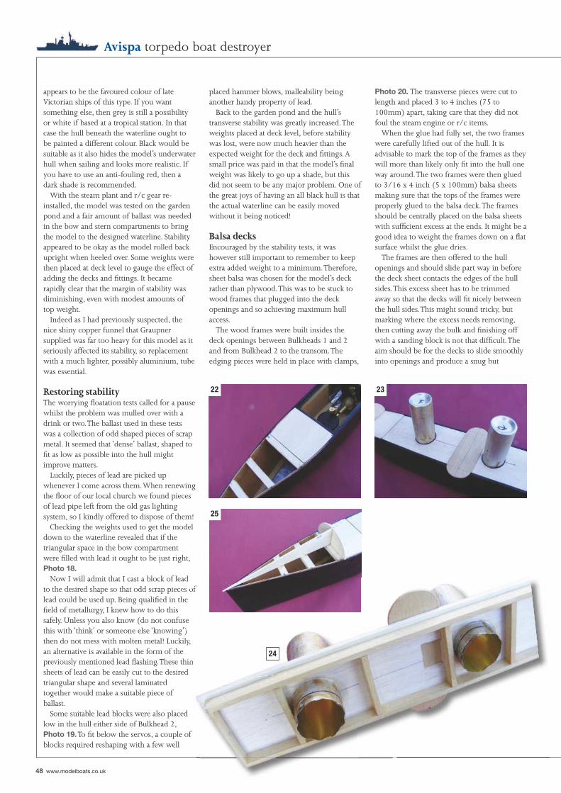
48 www.modelboats.co.uk
Avispa torpedo boat destroyer
appears to be the favoured colour of late Victorian ships of this type. If you want something else, then grey is still a possibility or white if based at a tropical station. In that case the hull beneath the waterline ought to be painted a different colour. Black would be suitable as it also hides the model’s underwater hull when sailing and looks more realistic. If you have to use an anti-fouling red, then a dark shade is recommended.
With the steam plant and r/c gear re-installed, the model was tested on the garden pond and a fair amount of ballast was needed in the bow and stern compartments to bring the model to the designed waterline. Stability appeared to be okay as the model rolled back upright when heeled over. Some weights were then placed at deck level to gauge the effect of adding the decks and fi ttings. It became rapidly clear that the margin of stability was diminishing, even with modest amounts of top weight.
Indeed as I had previously suspected, the nice shiny copper funnel that Graupner supplied was far too heavy for this model as it seriously affected its stability, so replacement with a much lighter, possibly aluminium, tube was essential.
Restoring stabilityThe worrying fl oatation tests called for a pause whilst the problem was mulled over with a drink or two. The ballast used in these tests was a collection of odd shaped pieces of scrap metal. It seemed that ‘dense’ ballast, shaped to fi t as low as possible into the hull might improve matters.
Luckily, pieces of lead are picked up whenever I come across them. When renewing the fl oor of our local church we found pieces of lead pipe left from the old gas lighting system, so I kindly offered to dispose of them!
Checking the weights used to get the model down to the waterline revealed that if the triangular space in the bow compartment were fi lled with lead it ought to be just right, Photo 18.
Now I will admit that I cast a block of lead to the desired shape so that odd scrap pieces of lead could be used up. Being qualifi ed in the fi eld of metallurgy, I knew how to do this safely. Unless you also know (do not confuse this with ‘think’ or someone else ‘knowing’) then do not mess with molten metal! Luckily, an alternative is available in the form of the previously mentioned lead fl ashing. These thin sheets of lead can be easily cut to the desired triangular shape and several laminated together would make a suitable piece of ballast.
Some suitable lead blocks were also placed low in the hull either side of Bulkhead 2, Photo 19. To fi t below the servos, a couple of blocks required reshaping with a few well
placed hammer blows, malleability being another handy property of lead.
Back to the garden pond and the hull’s transverse stability was greatly increased. The weights placed at deck level, before stability was lost, were now much heavier than the expected weight for the deck and fi ttings. A small price was paid in that the model’s fi nal weight was likely to go up a shade, but this did not seem to be any major problem. One of the great joys of having an all black hull is that the actual waterline can be easily moved without it being noticed!
Balsa decksEncouraged by the stability tests, it was however still important to remember to keep extra added weight to a minimum. Therefore, sheet balsa was chosen for the model’s deck rather than plywood. This was to be stuck to wood frames that plugged into the deck openings and so achieving maximum hull access.
The wood frames were built insides the deck openings between Bulkheads 1 and 2 and from Bulkhead 2 to the transom. The edging pieces were held in place with clamps,
Photo 20. The transverse pieces were cut to length and placed 3 to 4 inches (75 to 100mm) apart, taking care that they did not foul the steam engine or r/c items.
When the glue had fully set, the two frames were carefully lifted out of the hull. It is advisable to mark the top of the frames as they will more than likely only fi t into the hull one way around. The two frames were then glued to 3/16 x 4 inch (5 x 100mm) balsa sheets making sure that the tops of the frames were properly glued to the balsa deck. The frames should be centrally placed on the balsa sheets with suffi cient excess at the ends. It might be a good idea to weight the frames down on a fl at surface whilst the glue dries.
The frames are then offered to the hull openings and should slide part way in before the deck sheet contacts the edges of the hull sides. This excess sheet has to be trimmed away so that the decks will fi t nicely between the hull sides. This might sound tricky, but marking where the excess needs removing, then cutting away the bulk and fi nishing off with a sanding block is not that diffi cult. The aim should be for the decks to slide smoothly into openings and produce a snug but
es of he
se ) y,
n
22 23
25
24
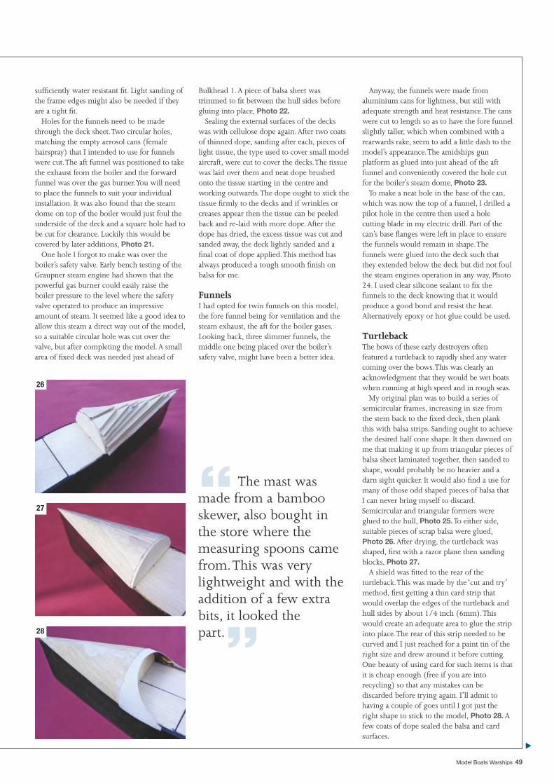
Model Boats Warships 49
suffi ciently water resistant fi t. Light sanding of the frame edges might also be needed if they are a tight fi t.
Holes for the funnels need to be made through the deck sheet. Two circular holes, matching the empty aerosol cans (female hairspray) that I intended to use for funnels were cut. The aft funnel was positioned to take the exhaust from the boiler and the forward funnel was over the gas burner. You will need to place the funnels to suit your individual installation. It was also found that the steam dome on top of the boiler would just foul the underside of the deck and a square hole had to be cut for clearance. Luckily this would be covered by later additions, Photo 21.
One hole I forgot to make was over the boiler’s safety valve. Early bench testing of the Graupner steam engine had shown that the powerful gas burner could easily raise the boiler pressure to the level where the safety valve operated to produce an impressive amount of steam. It seemed like a good idea to allow this steam a direct way out of the model, so a suitable circular hole was cut over the valve, but after completing the model. A small area of fi xed deck was needed just ahead of
Bulkhead 1. A piece of balsa sheet was trimmed to fi t between the hull sides before gluing into place, Photo 22.
Sealing the external surfaces of the decks was with cellulose dope again. After two coats of thinned dope, sanding after each, pieces of light tissue, the type used to cover small model aircraft, were cut to cover the decks. The tissue was laid over them and neat dope brushed onto the tissue starting in the centre and working outwards. The dope ought to stick the tissue fi rmly to the decks and if wrinkles or creases appear then the tissue can be peeled back and re-laid with more dope. After the dope has dried, the excess tissue was cut and sanded away, the deck lightly sanded and a fi nal coat of dope applied. This method has always produced a tough smooth fi nish on balsa for me.
FunnelsI had opted for twin funnels on this model, the fore funnel being for ventilation and the steam exhaust, the aft for the boiler gases. Looking back, three slimmer funnels, the middle one being placed over the boiler’s safety valve, might have been a better idea.
Anyway, the funnels were made from aluminium cans for lightness, but still with adequate strength and heat resistance. The cans were cut to length so as to have the fore funnel slightly taller, which when combined with a rearwards rake, seem to add a little dash to the model’s appearance. The amidships gun platform as glued into just ahead of the aft funnel and conveniently covered the hole cut for the boiler’s steam dome, Photo 23.
To make a neat hole in the base of the can, which was now the top of a funnel, I drilled a pilot hole in the centre then used a hole cutting blade in my electric drill. Part of the can’s base fl anges were left in place to ensure the funnels would remain in shape. The funnels were glued into the deck such that they extended below the deck but did not foul the steam engines operation in any way, Photo 24. I used clear silicone sealant to fi x the funnels to the deck knowing that it would produce a good bond and resist the heat. Alternatively epoxy or hot glue could be used.
TurtlebackThe bows of these early destroyers often featured a turtleback to rapidly shed any water coming over the bows. This was clearly an acknowledgment that they would be wet boats when running at high speed and in rough seas.
My original plan was to build a series of semicircular frames, increasing in size from the stem back to the fi xed deck, then plank this with balsa strips. Sanding ought to achieve the desired half cone shape. It then dawned on me that making it up from triangular pieces of balsa sheet laminated together, then sanded to shape, would probably be no heavier and a darn sight quicker. It would also fi nd a use for many of those odd shaped pieces of balsa that I can never bring myself to discard. Semicircular and triangular formers were glued to the hull, Photo 25. To either side, suitable pieces of scrap balsa were glued, Photo 26. After drying, the turtleback was shaped, fi rst with a razor plane then sanding blocks, Photo 27.
A shield was fi tted to the rear of the turtleback. This was made by the ‘cut and try’ method, fi rst getting a thin card strip that would overlap the edges of the turtleback and hull sides by about 1/4 inch (6mm). This would create an adequate area to glue the strip into place. The rear of this strip needed to be curved and I just reached for a paint tin of the right size and drew around it before cutting. One beauty of using card for such items is that it is cheap enough (free if you are into recycling) so that any mistakes can be discarded before trying again. I’ll admit to having a couple of goes until I got just the right shape to stick to the model, Photo 28. A few coats of dope sealed the balsa and card surfaces.
26
27
28
“ The mast was made from a bamboo skewer, also bought in the store where the measuring spoons came from. This was very lightweight and with the addition of a few extra bits, it looked the part.”
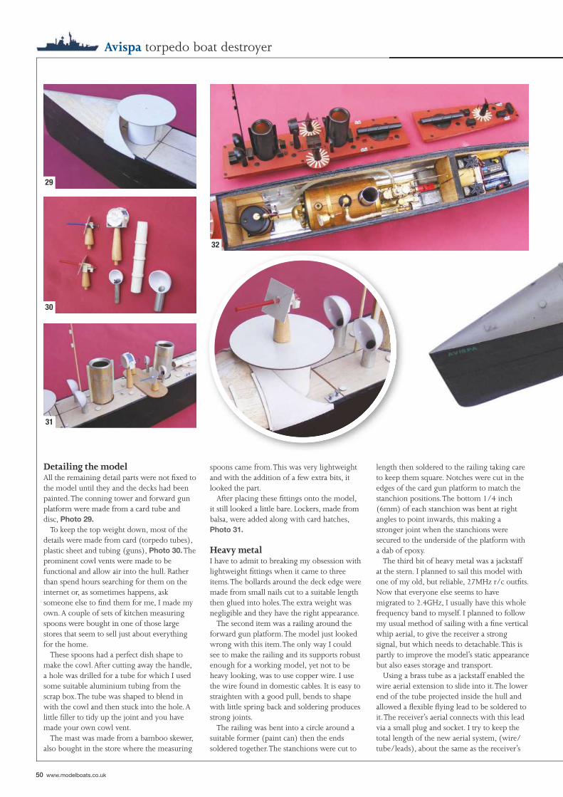
50 www.modelboats.co.uk
Avispa torpedo boat destroyer
Detailing the modelAll the remaining detail parts were not fi xed to the model until they and the decks had been painted. The conning tower and forward gun platform were made from a card tube and disc, Photo 29.
To keep the top weight down, most of the details were made from card (torpedo tubes), plastic sheet and tubing (guns), Photo 30. The prominent cowl vents were made to be functional and allow air into the hull. Rather than spend hours searching for them on the internet or, as sometimes happens, ask someone else to fi nd them for me, I made my own. A couple of sets of kitchen measuring spoons were bought in one of those large stores that seem to sell just about everything for the home.
These spoons had a perfect dish shape to make the cowl. After cutting away the handle, a hole was drilled for a tube for which I used some suitable aluminium tubing from the scrap box. The tube was shaped to blend in with the cowl and then stuck into the hole. A little fi ller to tidy up the joint and you have made your own cowl vent.
The mast was made from a bamboo skewer, also bought in the store where the measuring
spoons came from. This was very lightweight and with the addition of a few extra bits, it looked the part.
After placing these fi ttings onto the model, it still looked a little bare. Lockers, made from balsa, were added along with card hatches, Photo 31.
Heavy metalI have to admit to breaking my obsession with lightweight fi ttings when it came to three items. The bollards around the deck edge were made from small nails cut to a suitable length then glued into holes. The extra weight was negligible and they have the right appearance.
The second item was a railing around the forward gun platform. The model just looked wrong with this item. The only way I could see to make the railing and its supports robust enough for a working model, yet not to be heavy looking, was to use copper wire. I use the wire found in domestic cables. It is easy to straighten with a good pull, bends to shape with little spring back and soldering produces strong joints.
The railing was bent into a circle around a suitable former (paint can) then the ends soldered together. The stanchions were cut to
length then soldered to the railing taking care to keep them square. Notches were cut in the edges of the card gun platform to match the stanchion positions. The bottom 1/4 inch (6mm) of each stanchion was bent at right angles to point inwards, this making a stronger joint when the stanchions were secured to the underside of the platform with a dab of epoxy.
The third bit of heavy metal was a jackstaff at the stern. I planned to sail this model with one of my old, but reliable, 27MHz r/c outfi ts. Now that everyone else seems to have migrated to 2.4GHz, I usually have this whole frequency band to myself. I planned to follow my usual method of sailing with a fi ne vertical whip aerial, to give the receiver a strong signal, but which needs to detachable. This is partly to improve the model’s static appearance but also eases storage and transport.
Using a brass tube as a jackstaff enabled the wire aerial extension to slide into it. The lower end of the tube projected inside the hull and allowed a fl exible fl ying lead to be soldered to it. The receiver’s aerial connects with this lead via a small plug and socket. I try to keep the total length of the new aerial system, (wire/tube/leads), about the same as the receiver’s
29
30
32
31
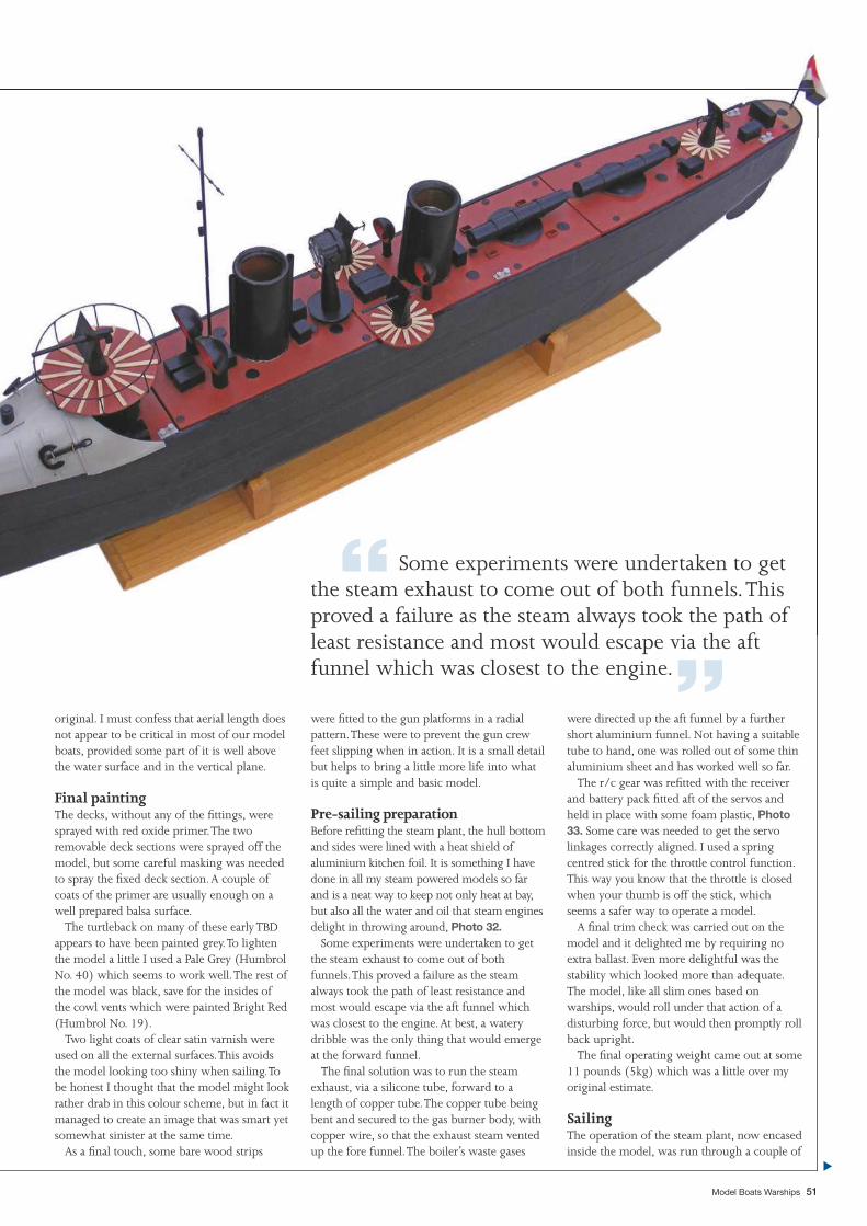
Model Boats Warships 51
original. I must confess that aerial length does not appear to be critical in most of our model boats, provided some part of it is well above the water surface and in the vertical plane.
Final paintingThe decks, without any of the fi ttings, were sprayed with red oxide primer. The two removable deck sections were sprayed off the model, but some careful masking was needed to spray the fi xed deck section. A couple of coats of the primer are usually enough on a well prepared balsa surface.
The turtleback on many of these early TBD appears to have been painted grey. To lighten the model a little I used a Pale Grey (Humbrol No. 40) which seems to work well. The rest of the model was black, save for the insides of the cowl vents which were painted Bright Red (Humbrol No. 19).
Two light coats of clear satin varnish were used on all the external surfaces. This avoids the model looking too shiny when sailing. To be honest I thought that the model might look rather drab in this colour scheme, but in fact it managed to create an image that was smart yet somewhat sinister at the same time.
As a fi nal touch, some bare wood strips
were fi tted to the gun platforms in a radial pattern. These were to prevent the gun crew feet slipping when in action. It is a small detail but helps to bring a little more life into what is quite a simple and basic model.
Pre-sailing preparationBefore refi tting the steam plant, the hull bottom and sides were lined with a heat shield of aluminium kitchen foil. It is something I have done in all my steam powered models so far and is a neat way to keep not only heat at bay, but also all the water and oil that steam engines delight in throwing around, Photo 32.
Some experiments were undertaken to get the steam exhaust to come out of both funnels. This proved a failure as the steam always took the path of least resistance and most would escape via the aft funnel which was closest to the engine. At best, a watery dribble was the only thing that would emerge at the forward funnel.
The fi nal solution was to run the steam exhaust, via a silicone tube, forward to a length of copper tube. The copper tube being bent and secured to the gas burner body, with copper wire, so that the exhaust steam vented up the fore funnel. The boiler’s waste gases
were directed up the aft funnel by a further short aluminium funnel. Not having a suitable tube to hand, one was rolled out of some thin aluminium sheet and has worked well so far.
The r/c gear was refi tted with the receiver and battery pack fi tted aft of the servos and held in place with some foam plastic, Photo 33. Some care was needed to get the servo linkages correctly aligned. I used a spring centred stick for the throttle control function. This way you know that the throttle is closed when your thumb is off the stick, which seems a safer way to operate a model.
A fi nal trim check was carried out on the model and it delighted me by requiring no extra ballast. Even more delightful was the stability which looked more than adequate. The model, like all slim ones based on warships, would roll under that action of a disturbing force, but would then promptly roll back upright.
The fi nal operating weight came out at some 11 pounds (5kg) which was a little over my original estimate.
SailingThe operation of the steam plant, now encased inside the model, was run through a couple of
“ Some experiments were undertaken to get the steam exhaust to come out of both funnels. This proved a failure as the steam always took the path of least resistance and most would escape via the aft funnel which was closest to the engine.”
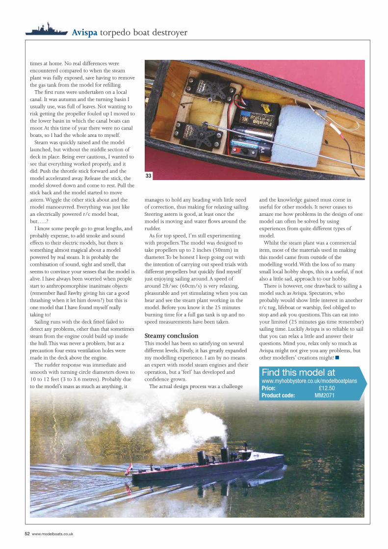
52 www.modelboats.co.uk
Avispa torpedo boat destroyer
times at home. No real differences were encountered compared to when the steam plant was fully exposed, save having to remove the gas tank from the model for refi lling.
The fi rst runs were undertaken on a local canal. It was autumn and the turning basin I usually use, was full of leaves. Not wanting to risk getting the propeller fouled up I moved to the lower basin in which the canal boats can moor. At this time of year there were no canal boats, so I had the whole area to myself.
Steam was quickly raised and the model launched, but without the middle section of deck in place. Being ever cautious, I wanted to see that everything worked properly, and it did. Push the throttle stick forward and the model accelerated away. Release the stick, the model slowed down and come to rest. Pull the stick back and the model started to move astern. Wiggle the other stick about and the model manoeuvred. Everything was just like an electrically powered r/c model boat, but…..?
I know some people go to great lengths, and probably expense, to add smoke and sound effects to their electric models, but there is something almost magical about a model powered by real steam. It is probably the combination of sound, sight and smell, that seems to convince your senses that the model is alive. I have always been worried when people start to anthropomorphise inanimate objects (remember Basil Fawlty giving his car a good thrashing when it let him down?) but this is one model that I have found myself really taking to!
Sailing runs with the deck fi tted failed to detect any problems, other than that sometimes steam from the engine could build up inside the hull. This was never a problem, but as a precaution four extra ventilation holes were made in the deck above the engine.
The rudder response was immediate and smooth with turning circle diameters down to 10 to 12 feet (3 to 3.6 metres). Probably due to the model’s mass as much as anything, it
manages to hold any heading with little need of correction, thus making for relaxing sailing. Steering astern is good, at least once the model is moving and water fl ows around the rudder.
As for top speed, I’m still experimenting with propellers. The model was designed to take propellers up to 2 inches (50mm) in diameter. To be honest I keep going out with the intention of carrying out speed trials with different propellers but quickly fi nd myself just enjoying sailing around. A speed of around 2ft/sec (60cm/s) is very relaxing, pleasurable and yet stimulating when you can hear and see the steam plant working in the model. Before you know it the 25 minutes burning time for a full gas tank is up and no speed measurements have been taken.
Steamy conclusionThis model has been so satisfying on several different levels. Firstly, it has greatly expanded my modelling experience. I am by no means an expert with model steam engines and their operation, but a ‘feel’ has developed and confi dence grown.
The actual design process was a challenge
and the knowledge gained must come in useful for other models. It never ceases to amaze me how problems in the design of one model can often be solved by using experiences from quite different types of model.
Whilst the steam plant was a commercial item, most of the materials used in making this model came from outside of the modelling world. With the loss of so many small local hobby shops, this is a useful, if not also a little sad, approach to our hobby.
There is however, one drawback to sailing a model such as Avispa. Spectators, who probably would show little interest in another r/c tug, lifeboat or warship, feel obliged to stop and ask you questions. This can eat into your limited (25 minutes gas time remember) sailing time. Luckily Avispa is so reliable to sail that you can relax a little and answer their questions. Mind you, relax only so much as Avispa might not give you any problems, but other modellers’ creations might!
Find this model atwww.myhobbystore.co.uk/modelboatplansPrice: £12.50Product code: MM2071
33
■
Great Books for Ship Modelers and Ship Lovers
Order by phone or online.
PHONE: 541-997-4439 FAX: 541-997-1282
SeaWatchBooks, llc
SEAWATCHBOOKS.COMPHONE: 541-997-4439 FAX: 541-997-1282
DAVID ANTSCHERL, ED TOSTI, ALLAN YEDLINSKY, GIB MCARDLE, ROB NAPIER, THE KRIEGSTEIN BROTHERS, AB HOVING
seawatchbooks.com
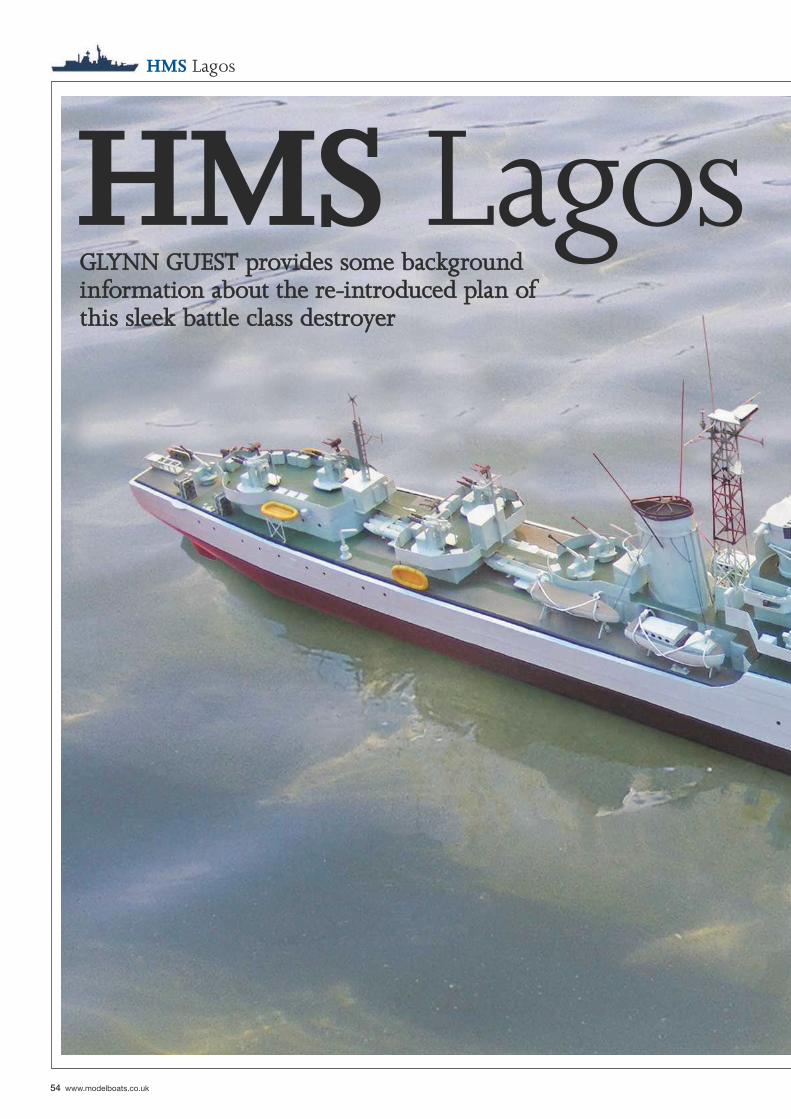
54 www.modelboats.co.uk
HMS Lagos
HMS LagosGLYNN GUEST provides some background GLYNN GUEST provides some background information about the re-introduced plan of information about the re-introduced plan of this sleek battle class destroyerthis sleek battle class destroyer
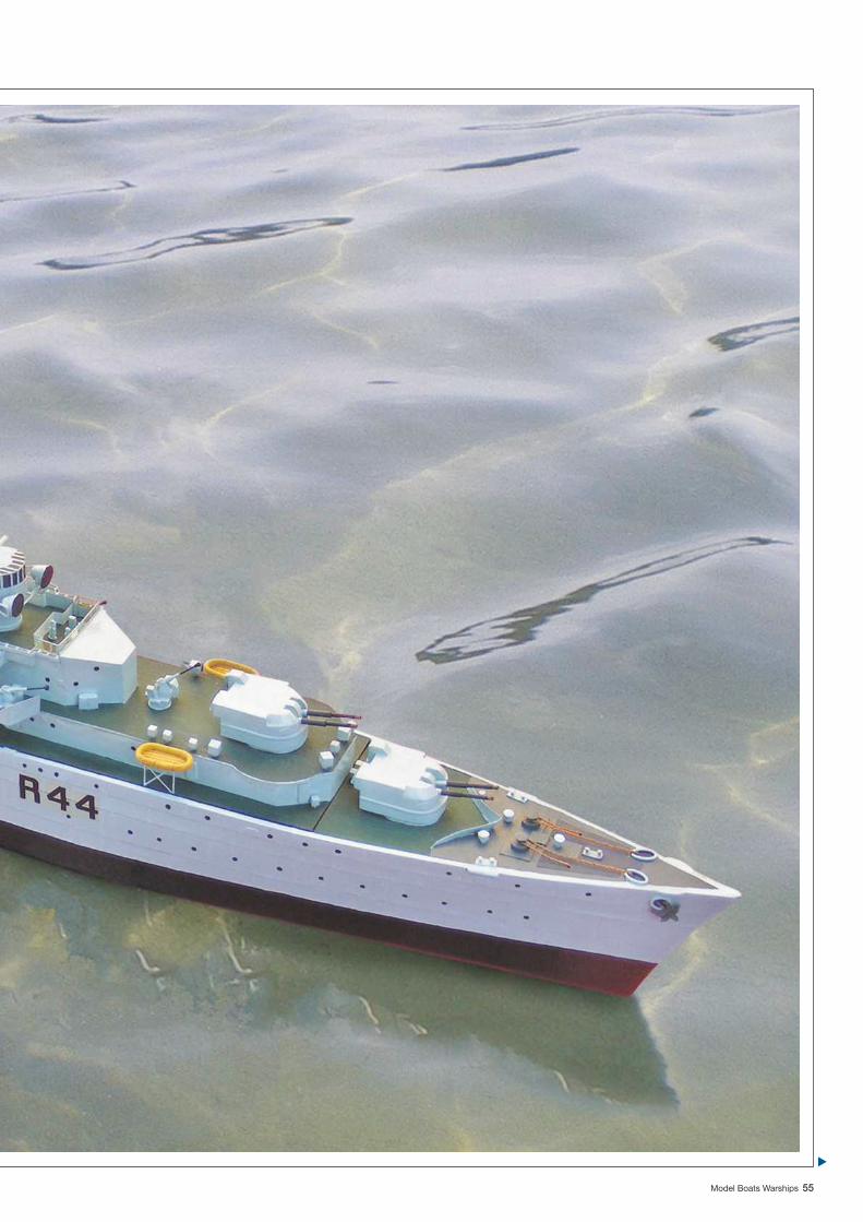
Model Boats Warships 55
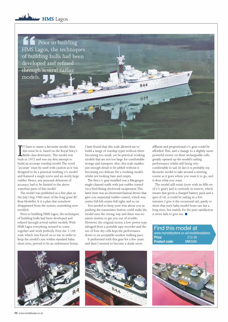
“ Prior to building HMS Lagos, the techniques of building hulls had been developed and refi ned through several earlier models. ”
56 www.modelboats.co.uk
If I have to name a favourite model, then this must be it, based on the Royal Navy’s Battle class destroyers,. The model was
built in 1972 and was my fi rst attempt to build an accurate warship model. The word ‘accurate’ must be used with caution as it was designed to be a practical working r/c model and featured a single screw and an overly large rudder. Hence, any personal delusions of accuracy had to be limited to the above waterline parts of this model.
The model was published as a free plan in the July/Aug 1986 issue of the long gone RC Boat Modeller. It is a plan that somehow disappeared from the system, something now rectifi ed.
Prior to building HMS Lagos, the techniques of building hulls had been developed and refi ned through several earlier models. With HMS Lagos everything seemed to come together and work perfectly. Even the 1:144 scale which was forced on to me in order to keep the model’s size within standard balsa sheet sizes, proved to be an unforeseen bonus.
affl uent and proportional r/c gear could be afforded. This, and a change to a slightly more powerful motor on three rechargeable cells, greatly opened up the model’s sailing performance whilst still being very comfortable to sail. In fact it is probably my favourite model to take around a steering course as it goes where you want it to go, and it does what you want.
The model still exists (now with its fi fth set of r/c gear) and is currently in reserve, which means that given a charged battery pack and a spot of oil, it could be sailing in a few minutes. I give it the occasional sail, partly to show that such balsa model boats can last a long time, but mainly for the pure satisfaction it never fails to give me.
Find this model atwww.myhobbystore.co.uk/modelboatplansPrice: £12.50Product code: MM2060
I later found that this scale allowed me to build a range of warship types without them becoming too small, yet be practical working models that are not too large for comfortable storage and transport. Also, this scale enables just enough detail to be added without it becoming too delicate for a working model, whilst not looking bare and empty.
The fi rst r/c gear installed was a Macgregor single channel outfi t with just rudder control via a Fred Rising clockwork escapement. This latter item was an electromechanical device that gave you sequential rudder control, which was; centre-full left-centre-full right, and so on.
You needed to keep your wits about you as pushing the transmitter button could make the model turn the wrong way and there was no astern motion to get you out of trouble. However, the original motor, a low power type salvaged from a portable tape recorder and the use of four dry cells kept the performance down to an acceptable modest walking pace.
It performed with this gear for a few years and then I seemed to become a shade more
HMS Lagos
■
The two were the basically the same, the LCM6 being 6ft longer than the LCM3 to provided the additional buoyancy needed to carry the heavier Sherman tanks of the war in the Pacifi c. A perfect partner to Tamiya’s 1/16 radio controlled Sherman and the halftracks currently available. The kit was designed with this tough use in mind.● The hulls are hand-laid GRP and feature the buckled panels from the welding process, for that ‘starved dog’ look. They are a super mouldings, very strong and light with lots of nice touches. ● All the bulkheads, inner walls, fl oors and wheelhouse are made from laser-cut ABS. This makes for easy assembly because everything fi ts perfectly and ABS is very tough and easy to glue. ● Smaller, detailing parts are made from white acrylic sheet ensuring they are cut very cleanly.
Two 1/16 scale LCM3 & LCM6 Landing craft.We have been making the LCM3 for a couple of years now and have been asked many times (mostly by ex-US troops) if we could make the LCM6 too. Well, we have. They are now both available.
See our website (www.speedlinemodels.com) for more information details TEL: 01455 637658
● The decks are covered in authentic scale checker-plate, laser cut to shape.● All castings are resin and include the two 0.5 Browning machine guns, the engine room ventilators, rope fenders and truck tyres, steering wheel, throttle levers, fi re extinguisher and bollards. ● The ‘weld seams’ on the wheelhouse are made from etched brass to give a very authentic look.● A substantial etched brass fabrication carries the motors, the rudder servo and the door opening mechanism, all accessible by lifting off the rear deck and wheelhouse.● Brass prop-shaft tubes, fi tted with bronze bearings and stainless steel
shafts carry the two scale cast brass propellers. ● The two drive couplings are included. ● Heavy gauge etched brass is used to make many fabricated parts including the keels, gun mounts and shields, brackets for the door lifting mechanism, railing bosses and instrument panel among others.● Vinyl lettering set is supplied for both US and British versions as are the optional parts required for the British version.
The motors and sail winch are both available from Speedline.The 540 motors are £13 each, the sail winch is £35The specially commissioned set of three fi gures is available at £36 plus £3 postage (if ordered separately).LCM3 is £395 and the LCM6 is £415.
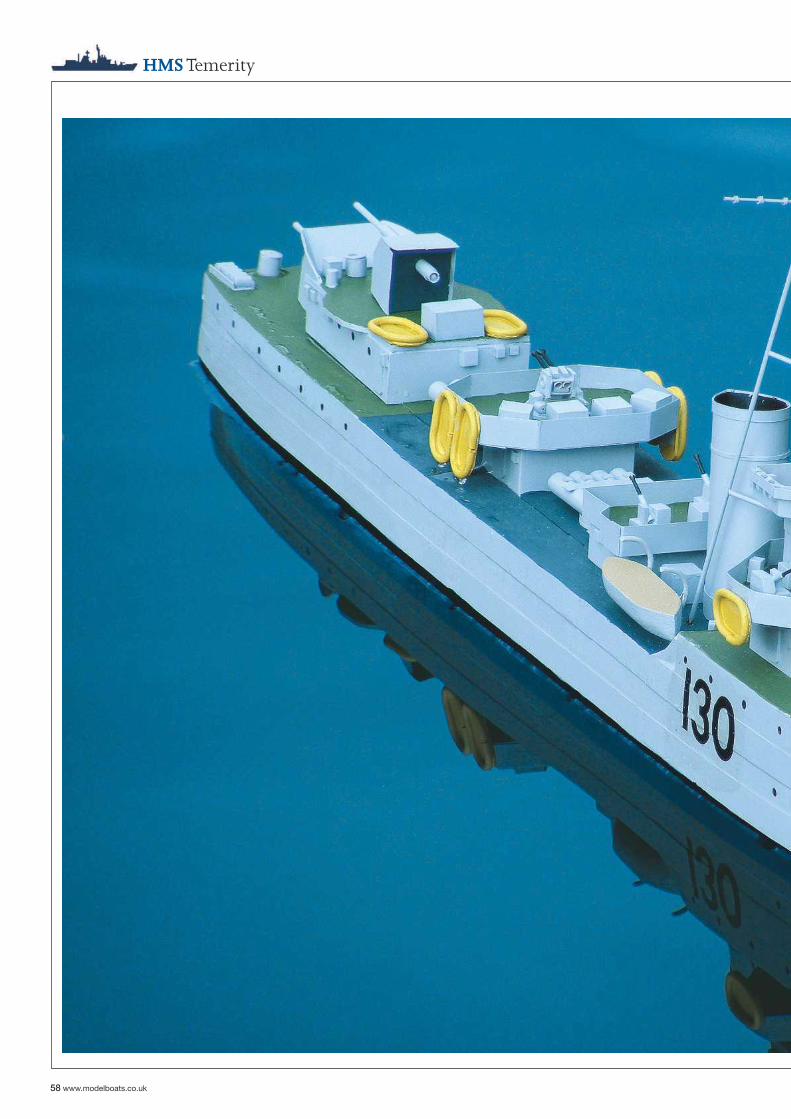
HMS Temerity
58 www.modelboats.co.uk
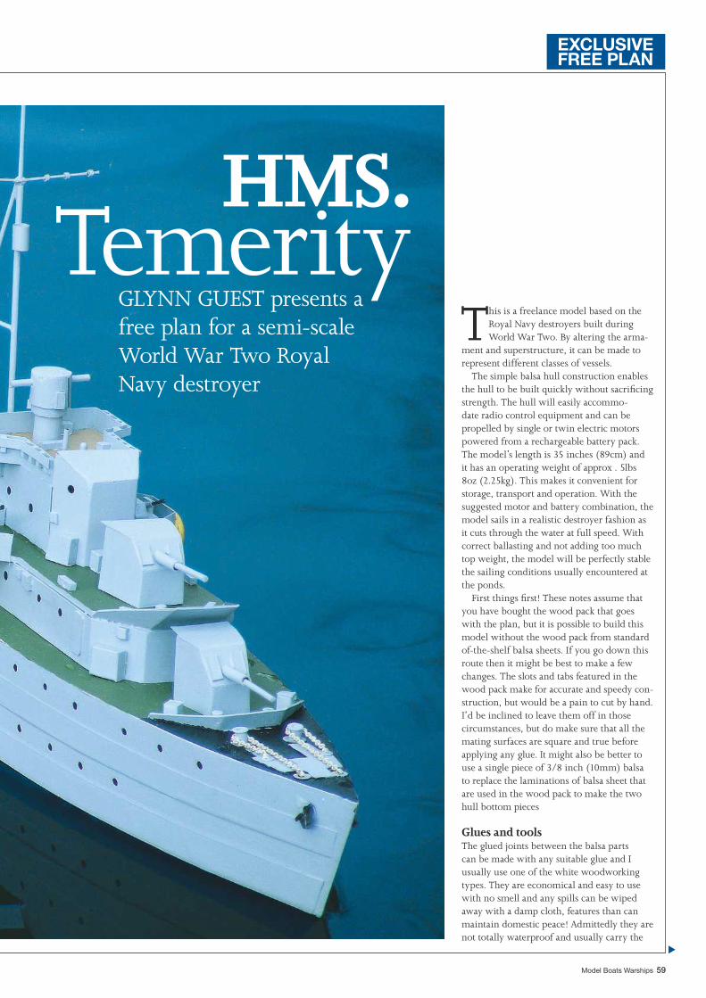
Model Boats Warships 59
This is a freelance model based on the Royal Navy destroyers built during World War Two. By altering the arma-
ment and superstructure, it can be made to represent different classes of vessels.
The simple balsa hull construction enables the hull to be built quickly without sacrifi cing strength. The hull will easily accommo-date radio control equipment and can be propelled by single or twin electric motors powered from a rechargeable battery pack. The model’s length is 35 inches (89cm) and it has an operating weight of approx . 5lbs 8oz (2.25kg). This makes it convenient for storage, transport and operation. With the suggested motor and battery combination, the model sails in a realistic destroyer fashion as it cuts through the water at full speed. With correct ballasting and not adding too much top weight, the model will be perfectly stable the sailing conditions usually encountered at the ponds.
First things fi rst! These notes assume that you have bought the wood pack that goes with the plan, but it is possible to build this model without the wood pack from standard of-the-shelf balsa sheets. If you go down this route then it might be best to make a few changes. The slots and tabs featured in the wood pack make for accurate and speedy con-struction, but would be a pain to cut by hand. I’d be inclined to leave them off in those circumstances, but do make sure that all the mating surfaces are square and true before applying any glue. It might also be better to use a single piece of 3/8 inch (10mm) balsa to replace the laminations of balsa sheet that are used in the wood pack to make the two hull bottom pieces
Glues and toolsThe glued joints between the balsa parts can be made with any suitable glue and I usually use one of the white woodworking types. They are economical and easy to use with no smell and any spills can be wiped away with a damp cloth, features than can maintain domestic peace! Admittedly they are not totally waterproof and usually carry the
GLYNN GUEST presents a free plan for a semi-scale World War Two Royal Navy destroyer
HMS. Temerity
EXCLUSIVEFREE PLAN
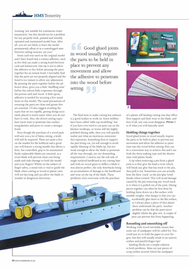
60 www.modelboats.co.uk
1
2
HMS Temerity
warning ‘not suitable for continuous water immersion’, but this should not be a problem for any properly built, painted and sensibly operated and maintained model boat. After all, you are not likely to leave the model permanently afl oat or in a waterlogged state between sailing sessions, are you?
Some card was used on the original model and I have found that a contact adhesive, such as Evo-Stik can make a strong bond between card and balsawood. One tip is not to allow the adhesive to dry before pressing the parts together for an instant bond. I inevitably fi nd that the parts are not properly aligned and the bond is too instant to allow any adjustment. By pressing the parts together before the ad-hesive dries, gives you a little ‘shuffl ing time’ before the solvent fully evaporates through the porous card and wood. A little epoxy adhesive is needed for securing a few metal items in this model. The usual precautions of ensuring the parts are clean and grease free are essential. I’d also suggest avoiding the types that set too rapidly, getting things accu-rately placed is much easier when you do not have to rush. Also, the slower setting types have more time to penetrate into surface irregularities and pores to create a stronger bond.
Even though the purchase of a wood pack will save you a lot of balsa cutting, a knife will still be required. There are quite a few on the market for the hobbyist and a good one will feature a strong handle that allows a fi rm, but controlled, grip to be maintained. Easily replaceable blades are essential, as a worn blade will prevent clean cuts being made and risks damage to both the model and your fi ngers! Whilst on the subject of fi nger safety, a metal rule is vital to guide the blade when cutting as wood or plastic ones will not last long and can allow the blade to wander in dangerous directions.
The fi nal item to make cutting less arduous is a good surface to work on. Some hobbies have been called ‘table top modelling’, but if you have ever tried to cut parts out on the kitchen worktops, or worse still the highly polished dining table, then you will quickly realise just what an enormous misnomer this represents. Something fi rm to support the part being cut, yet soft enough to avoid rapidly blunting of the blade tip, but not weak enough to allow the blade to penetrate all the way through, are our demanding requirements. I used to use the soft side of single surfaced hardboard as my cutting base and with no wood grain to defl ect a blade it was almost perfect, the only drawbacks being an accumulation of damage to the hardboard and wear on the tip of the blade. These problems were overcome with the purchase
of a plastic self-healing cutting mat that offers fi rm support and little wear to the blade, and best of all, any cuts soon disappear. Photo 1 is of what you will basically need.
Holding things togetherGood glued joints in wood usually require the parts to be held in place to prevent any movement and allow the adhesive to pene-trate into the wood before setting. Pins can be a convenient way to achieve this and I use both the dress making type and the shorter ones with plastic heads.
A tip when removing a pin from a glued joint is to fi rst give the head a twist which will break any glue that has stuck to the pin, then pull it out. Sometimes you can actually hear the faint ‘crack’ as the pin/glue bond breaks when twisted. This will avoid damage caused by the pin removing any wood stuck to it when it is pulled out of the joint. Gluing pieces together can often be best done by holding them down on a fl at surface with suitable weights. One danger is that you can
accidentally glue them to the fl at surface, so I always place a piece of thin plastic sheet underneath the parts. Another problem can be that the parts move slightly whilst the glue sets. A couple of pins can prevent this from happening.
Rounding and smoothing offWorking with wood inevitably means that some use of sandpaper will be called for. You could just try to hold the paper in your fi n-gers, but this will usually result in an uneven surface and painful fi nger tips!
Sanding blocks are a simple solution to both problems. Mine are just pieces of scrap timber around which the sandpaper
“ Good glued joints in wood usually require the parts to be held in place to prevent any movement and allow the adhesive to penetrate into the wood before setting. ”
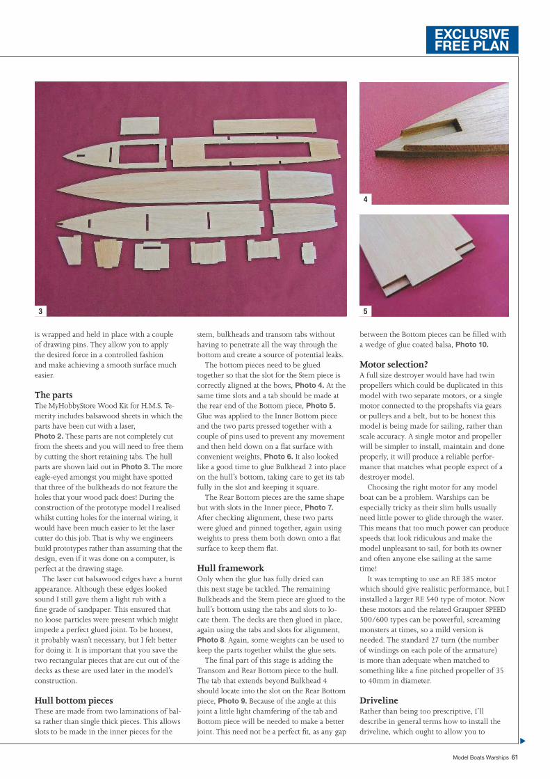
Model Boats Warships 61
3
4
5
is wrapped and held in place with a couple of drawing pins. They allow you to apply the desired force in a controlled fashion and make achieving a smooth surface much easier.
The partsThe MyHobbyStore Wood Kit for H.M.S. Te-merity includes balsawood sheets in which the parts have been cut with a laser, Photo 2. These parts are not completely cut from the sheets and you will need to free them by cutting the short retaining tabs. The hull parts are shown laid out in Photo 3. The more eagle-eyed amongst you might have spotted that three of the bulkheads do not feature the holes that your wood pack does! During the construction of the prototype model I realised whilst cutting holes for the internal wiring, it would have been much easier to let the laser cutter do this job. That is why we engineers build prototypes rather than assuming that the design, even if it was done on a computer, is perfect at the drawing stage.
The laser cut balsawood edges have a burnt appearance. Although these edges looked sound I still gave them a light rub with a fi ne grade of sandpaper. This ensured that no loose particles were present which might impede a perfect glued joint. To be honest, it probably wasn’t necessary, but I felt better for doing it. It is important that you save the two rectangular pieces that are cut out of the decks as these are used later in the model’s construction.
Hull bottom piecesThese are made from two laminations of bal-sa rather than single thick pieces. This allows slots to be made in the inner pieces for the
stem, bulkheads and transom tabs without having to penetrate all the way through the bottom and create a source of potential leaks.
The bottom pieces need to be glued together so that the slot for the Stem piece is correctly aligned at the bows, Photo 4. At the same time slots and a tab should be made at the rear end of the Bottom piece, Photo 5. Glue was applied to the Inner Bottom piece and the two parts pressed together with a couple of pins used to prevent any movement and then held down on a fl at surface with convenient weights, Photo 6. It also looked like a good time to glue Bulkhead 2 into place on the hull’s bottom, taking care to get its tab fully in the slot and keeping it square.
The Rear Bottom pieces are the same shape but with slots in the Inner piece, Photo 7. After checking alignment, these two parts were glued and pinned together, again using weights to press them both down onto a fl at surface to keep them fl at.
Hull frameworkOnly when the glue has fully dried can this next stage be tackled. The remaining Bulkheads and the Stem piece are glued to the hull’s bottom using the tabs and slots to lo-cate them. The decks are then glued in place, again using the tabs and slots for alignment, Photo 8. Again, some weights can be used to keep the parts together whilst the glue sets.
The fi nal part of this stage is adding the Transom and Rear Bottom piece to the hull. The tab that extends beyond Bulkhead 4 should locate into the slot on the Rear Bottom piece, Photo 9. Because of the angle at this joint a little light chamfering of the tab and Bottom piece will be needed to make a better joint. This need not be a perfect fi t, as any gap
between the Bottom pieces can be fi lled with a wedge of glue coated balsa, Photo 10.
Motor selection?A full size destroyer would have had twin propellers which could be duplicated in this model with two separate motors, or a single motor connected to the propshafts via gears or pulleys and a belt, but to be honest this model is being made for sailing, rather than scale accuracy. A single motor and propeller will be simpler to install, maintain and done properly, it will produce a reliable perfor-mance that matches what people expect of a destroyer model.
Choosing the right motor for any model boat can be a problem. Warships can be especially tricky as their slim hulls usually need little power to glide through the water. This means that too much power can produce speeds that look ridiculous and make the model unpleasant to sail, for both its owner and often anyone else sailing at the same time!
It was tempting to use an RE 385 motor which should give realistic performance, but I installed a larger RE 540 type of motor. Now these motors and the related Graupner SPEED 500/600 types can be powerful, screaming monsters at times, so a mild version is needed. The standard 27 turn (the number of windings on each pole of the armature) is more than adequate when matched to something like a fi ne pitched propeller of 35 to 40mm in diameter.
DrivelineRather than being too prescriptive, I’ll describe in general terms how to install the driveline, which ought to allow you to
EXCLUSIVEFREE PLAN
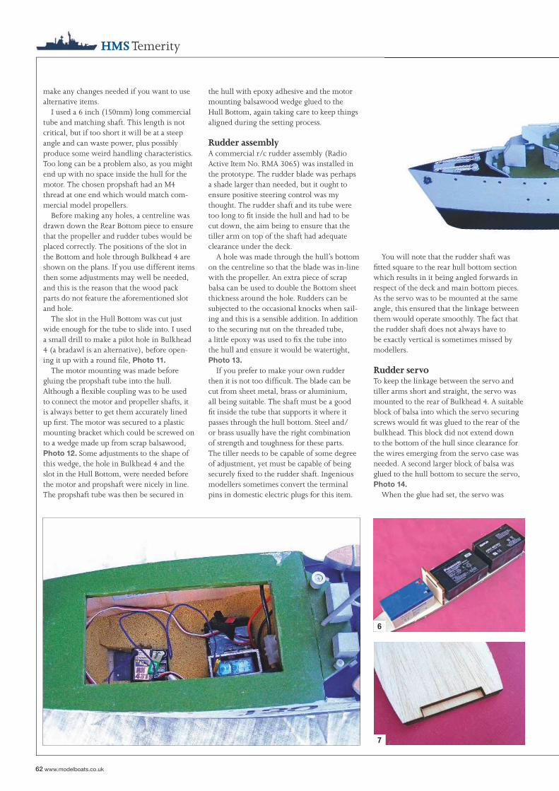
62 www.modelboats.co.uk
HMS Temerity
You will note that the rudder shaft was fi tted square to the rear hull bottom section which results in it being angled forwards in respect of the deck and main bottom pieces. As the servo was to be mounted at the same angle, this ensured that the linkage between them would operate smoothly. The fact that the rudder shaft does not always have to be exactly vertical is sometimes missed by modellers.
Rudder servoTo keep the linkage between the servo and tiller arms short and straight, the servo was mounted to the rear of Bulkhead 4. A suitable block of balsa into which the servo securing screws would fi t was glued to the rear of the bulkhead. This block did not extend down to the bottom of the hull since clearance for the wires emerging from the servo case was needed. A second larger block of balsa was glued to the hull bottom to secure the servo, Photo 14.
When the glue had set, the servo was
the hull with epoxy adhesive and the motor mounting balsawood wedge glued to the Hull Bottom, again taking care to keep things aligned during the setting process.
Rudder assemblyA commercial r/c rudder assembly (Radio Active Item No. RMA 3065) was installed in the prototype. The rudder blade was perhaps a shade larger than needed, but it ought to ensure positive steering control was my thought. The rudder shaft and its tube were too long to fi t inside the hull and had to be cut down, the aim being to ensure that the tiller arm on top of the shaft had adequate clearance under the deck.
A hole was made through the hull’s bottom on the centreline so that the blade was in-line with the propeller. An extra piece of scrap balsa can be used to double the Bottom sheet thickness around the hole. Rudders can be subjected to the occasional knocks when sail-ing and this is a sensible addition. In addition to the securing nut on the threaded tube, a little epoxy was used to fi x the tube into the hull and ensure it would be watertight, Photo 13.
If you prefer to make your own rudder then it is not too diffi cult. The blade can be cut from sheet metal, brass or aluminium, all being suitable. The shaft must be a good fi t inside the tube that supports it where it passes through the hull bottom. Steel and/or brass usually have the right combination of strength and toughness for these parts. The tiller needs to be capable of some degree of adjustment, yet must be capable of being securely fi xed to the rudder shaft. Ingenious modellers sometimes convert the terminal pins in domestic electric plugs for this item.
make any changes needed if you want to use alternative items.
I used a 6 inch (150mm) long commercial tube and matching shaft. This length is not critical, but if too short it will be at a steep angle and can waste power, plus possibly produce some weird handling characteristics. Too long can be a problem also, as you might end up with no space inside the hull for the motor. The chosen propshaft had an M4 thread at one end which would match com-mercial model propellers.
Before making any holes, a centreline was drawn down the Rear Bottom piece to ensure that the propeller and rudder tubes would be placed correctly. The positions of the slot in the Bottom and hole through Bulkhead 4 are shown on the plans. If you use different items then some adjustments may well be needed, and this is the reason that the wood pack parts do not feature the aforementioned slot and hole.
The slot in the Hull Bottom was cut just wide enough for the tube to slide into. I used a small drill to make a pilot hole in Bulkhead 4 (a bradawl is an alternative), before open-ing it up with a round fi le, Photo 11.
The motor mounting was made before gluing the propshaft tube into the hull. Although a fl exible coupling was to be used to connect the motor and propeller shafts, it is always better to get them accurately lined up fi rst. The motor was secured to a plastic mounting bracket which could be screwed on to a wedge made up from scrap balsawood, Photo 12. Some adjustments to the shape of this wedge, the hole in Bulkhead 4 and the slot in the Hull Bottom, were needed before the motor and propshaft were nicely in line. The propshaft tube was then be secured in
6
7
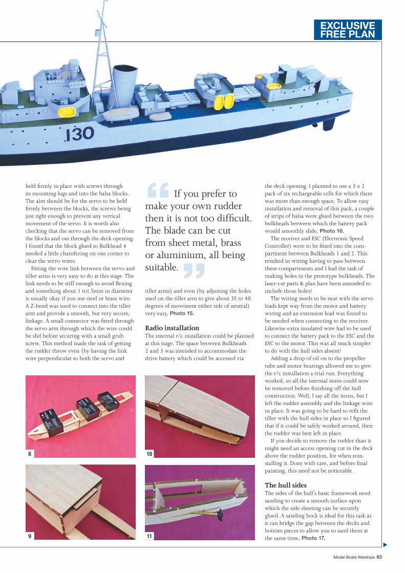
Model Boats Warships 63
the deck opening. I planned to use a 3 x 2 pack of six rechargeable cells for which there was more than enough space. To allow easy installation and removal of this pack, a couple of strips of balsa were glued between the two bulkheads between which the battery pack would smoothly slide, Photo 16.
The receiver and ESC (Electronic Speed Controller) were to be fi tted into the com-partment between Bulkheads 1 and 2. This resulted in wiring having to pass between these compartments and I had the task of making holes in the prototype bulkheads. The laser-cut parts & plan have been amended to include those holes!
The wiring needs to be neat with the servo leads kept way from the motor and battery wiring and an extension lead was found to be needed when connecting to the receiver. Likewise extra insulated wire had to be used to connect the battery pack to the ESC and the ESC to the motor. This was all much simpler to do with the hull sides absent!
Adding a drop of oil on to the propeller tube and motor bearings allowed me to give the r/c installation a trial run. Everything worked, so all the internal items could now be removed before fi nishing off the hull construction. Well, I say all the items, but I left the rudder assembly and the linkage wire in place. It was going to be hard to refi t the tiller with the hull sides in place so I fi gured that if it could be safely worked around, then the rudder was best left in place.
If you decide to remove the rudder than it might need an access opening cut in the deck above the rudder position, for when rein-stalling it. Done with care, and before fi nal painting, this need not be noticeable.
The hull sidesThe sides of the hull’s basic framework need sanding to create a smooth surface upon which the side sheeting can be securely glued. A sanding bock is ideal for this task as it can bridge the gap between the decks and bottom pieces to allow you to sand them at the same time, Photo 17.
held fi rmly in place with screws through its mounting lugs and into the balsa blocks. The aim should be for the servo to be held fi rmly between the blocks, the screws being just tight enough to prevent any vertical movement of the servo. It is worth also checking that the servo can be removed from the blocks and out through the deck opening. I found that the block glued to Bulkhead 4 needed a little chamfering on one corner to clear the servo wires.
Fitting the wire link between the servo and tiller arms is very easy to do at this stage. The link needs to be stiff enough to avoid fl exing and something about 1 to1.5mm in diameter is usually okay if you use steel or brass wire. A Z-bend was used to connect into the tiller arm and provide a smooth, but very secure, linkage. A small connector was fi tted through the servo arm through which the wire could be slid before securing with a small grub screw. This method made the task of getting the rudder throw even (by having the link wire perpendicular to both the servo and
tiller arms) and even (by adjusting the holes used on the tiller arm to give about 35 to 40 degrees of movement either side of neutral) very easy, Photo 15.
Radio installationThe internal r/c installation could be planned at this stage. The space between Bulkheads 2 and 3 was intended to accommodate the drive battery which could be accessed via
8
9
10
11
“ If you prefer to make your own rudder then it is not too diffi cult. The blade can be cut from sheet metal, brass or aluminium, all being suitable. ”
EXCLUSIVEFREE PLAN
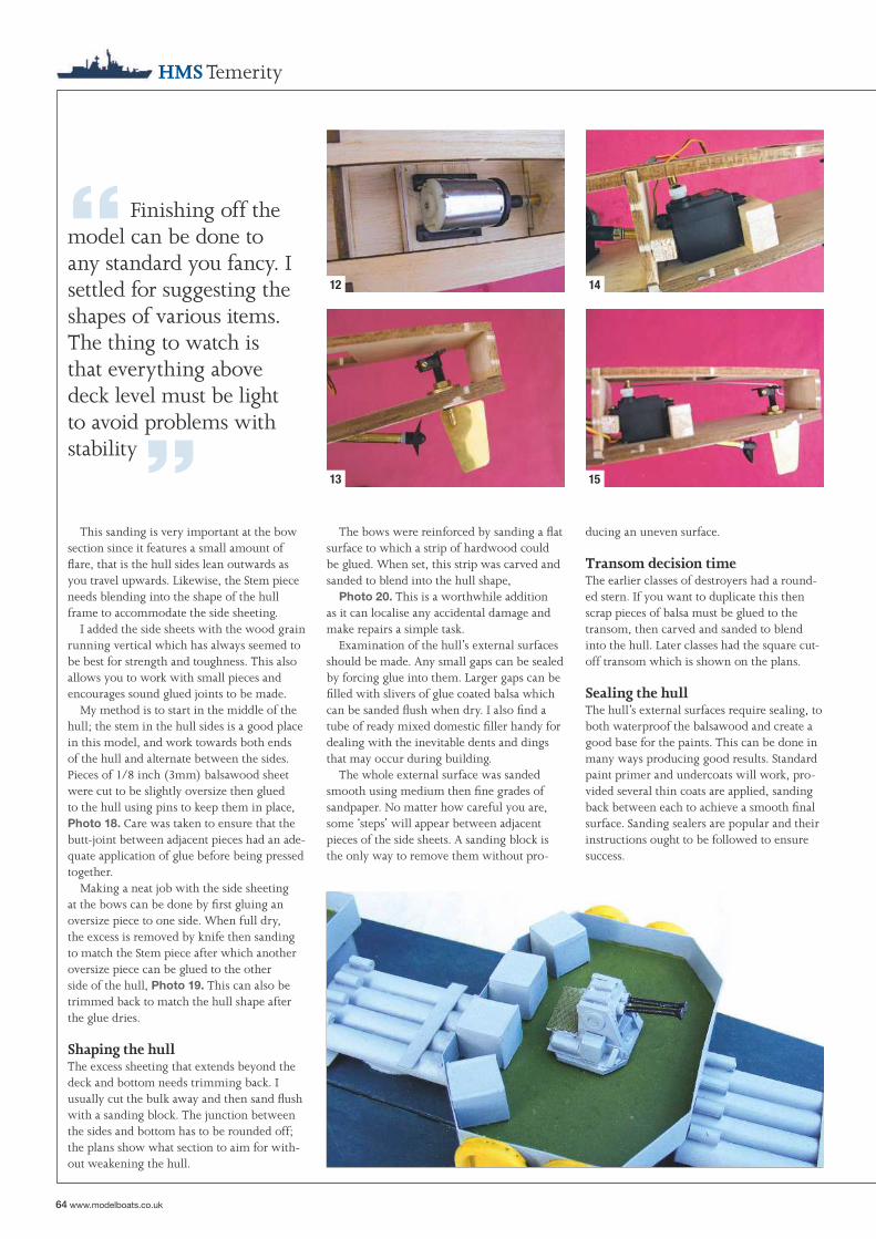
“ Finishing off the model can be done to any standard you fancy. I settled for suggesting the shapes of various items. The thing to watch is that everything above deck level must be light to avoid problems with stability ”
64 www.modelboats.co.uk
HMS Temerity
ducing an uneven surface.
Transom decision timeThe earlier classes of destroyers had a round-ed stern. If you want to duplicate this then scrap pieces of balsa must be glued to the transom, then carved and sanded to blend into the hull. Later classes had the square cut-off transom which is shown on the plans.
Sealing the hullThe hull’s external surfaces require sealing, to both waterproof the balsawood and create a good base for the paints. This can be done in many ways producing good results. Standard paint primer and undercoats will work, pro-vided several thin coats are applied, sanding back between each to achieve a smooth fi nal surface. Sanding sealers are popular and their instructions ought to be followed to ensure success.
The bows were reinforced by sanding a fl at surface to which a strip of hardwood could be glued. When set, this strip was carved and sanded to blend into the hull shape,
Photo 20. This is a worthwhile addition as it can localise any accidental damage and make repairs a simple task.
Examination of the hull’s external surfaces should be made. Any small gaps can be sealed by forcing glue into them. Larger gaps can be fi lled with slivers of glue coated balsa which can be sanded fl ush when dry. I also fi nd a tube of ready mixed domestic fi ller handy for dealing with the inevitable dents and dings that may occur during building.
The whole external surface was sanded smooth using medium then fi ne grades of sandpaper. No matter how careful you are, some ‘steps’ will appear between adjacent pieces of the side sheets. A sanding block is the only way to remove them without pro-
This sanding is very important at the bow section since it features a small amount of fl are, that is the hull sides lean outwards as you travel upwards. Likewise, the Stem piece needs blending into the shape of the hull frame to accommodate the side sheeting.
I added the side sheets with the wood grain running vertical which has always seemed to be best for strength and toughness. This also allows you to work with small pieces and encourages sound glued joints to be made.
My method is to start in the middle of the hull; the stem in the hull sides is a good place in this model, and work towards both ends of the hull and alternate between the sides. Pieces of 1/8 inch (3mm) balsawood sheet were cut to be slightly oversize then glued to the hull using pins to keep them in place, Photo 18. Care was taken to ensure that the butt-joint between adjacent pieces had an ade-quate application of glue before being pressed together.
Making a neat job with the side sheeting at the bows can be done by fi rst gluing an oversize piece to one side. When full dry, the excess is removed by knife then sanding to match the Stem piece after which another oversize piece can be glued to the other side of the hull, Photo 19. This can also be trimmed back to match the hull shape after the glue dries.
Shaping the hullThe excess sheeting that extends beyond the deck and bottom needs trimming back. I usually cut the bulk away and then sand fl ush with a sanding block. The junction between the sides and bottom has to be rounded off; the plans show what section to aim for with-out weakening the hull.
12
13
14
15
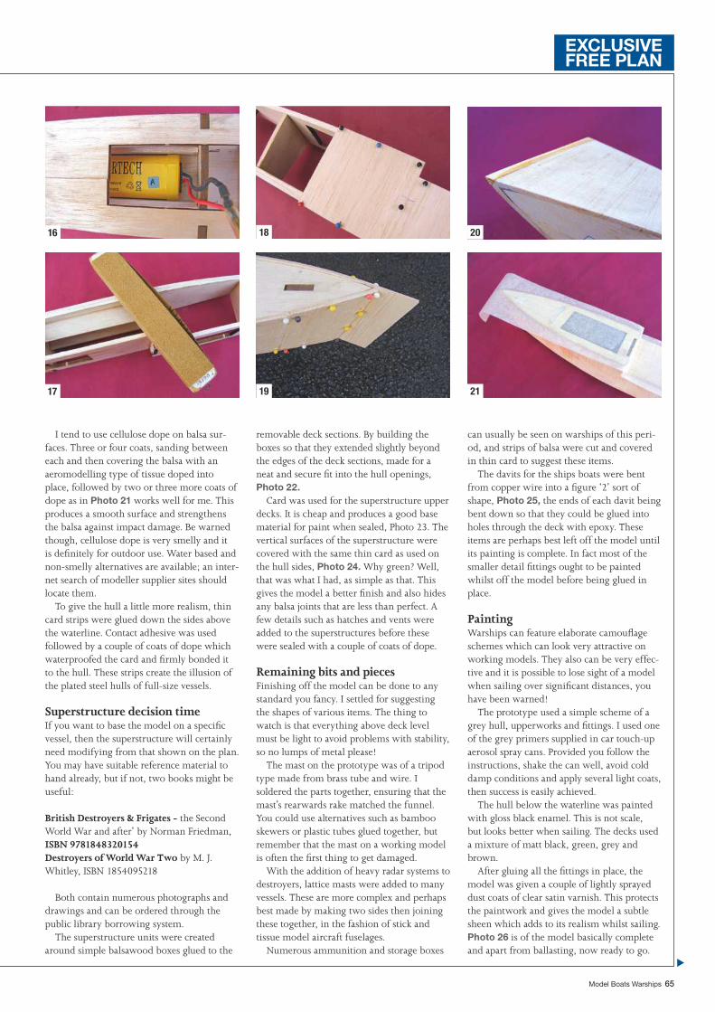
Model Boats Warships 65
can usually be seen on warships of this peri-od, and strips of balsa were cut and covered in thin card to suggest these items.
The davits for the ships boats were bent from copper wire into a fi gure ‘2’ sort of shape, Photo 25, the ends of each davit being bent down so that they could be glued into holes through the deck with epoxy. These items are perhaps best left off the model until its painting is complete. In fact most of the smaller detail fi ttings ought to be painted whilst off the model before being glued in place.
PaintingWarships can feature elaborate camoufl age schemes which can look very attractive on working models. They also can be very effec-tive and it is possible to lose sight of a model when sailing over signifi cant distances, you have been warned!
The prototype used a simple scheme of a grey hull, upperworks and fi ttings. I used one of the grey primers supplied in car touch-up aerosol spray cans. Provided you follow the instructions, shake the can well, avoid cold damp conditions and apply several light coats, then success is easily achieved.
The hull below the waterline was painted with gloss black enamel. This is not scale, but looks better when sailing. The decks used a mixture of matt black, green, grey and brown.
After gluing all the fi ttings in place, the model was given a couple of lightly sprayed dust coats of clear satin varnish. This protects the paintwork and gives the model a subtle sheen which adds to its realism whilst sailing. Photo 26 is of the model basically complete and apart from ballasting, now ready to go.
removable deck sections. By building the boxes so that they extended slightly beyond the edges of the deck sections, made for a neat and secure fi t into the hull openings, Photo 22.
Card was used for the superstructure upper decks. It is cheap and produces a good base material for paint when sealed, Photo 23. The vertical surfaces of the superstructure were covered with the same thin card as used on the hull sides, Photo 24. Why green? Well, that was what I had, as simple as that. This gives the model a better fi nish and also hides any balsa joints that are less than perfect. A few details such as hatches and vents were added to the superstructures before these were sealed with a couple of coats of dope.
Remaining bits and piecesFinishing off the model can be done to any standard you fancy. I settled for suggesting the shapes of various items. The thing to watch is that everything above deck level must be light to avoid problems with stability, so no lumps of metal please!
The mast on the prototype was of a tripod type made from brass tube and wire. I soldered the parts together, ensuring that the mast’s rearwards rake matched the funnel. You could use alternatives such as bamboo skewers or plastic tubes glued together, but remember that the mast on a working model is often the fi rst thing to get damaged.
With the addition of heavy radar systems to destroyers, lattice masts were added to many vessels. These are more complex and perhaps best made by making two sides then joining these together, in the fashion of stick and tissue model aircraft fuselages.
Numerous ammunition and storage boxes
I tend to use cellulose dope on balsa sur-faces. Three or four coats, sanding between each and then covering the balsa with an aeromodelling type of tissue doped into place, followed by two or three more coats of dope as in Photo 21 works well for me. This produces a smooth surface and strengthens the balsa against impact damage. Be warned though, cellulose dope is very smelly and it is defi nitely for outdoor use. Water based and non-smelly alternatives are available; an inter-net search of modeller supplier sites should locate them.
To give the hull a little more realism, thin card strips were glued down the sides above the waterline. Contact adhesive was used followed by a couple of coats of dope which waterproofed the card and fi rmly bonded it to the hull. These strips create the illusion of the plated steel hulls of full-size vessels.
Superstructure decision timeIf you want to base the model on a specifi c vessel, then the superstructure will certainly need modifying from that shown on the plan. You may have suitable reference material to hand already, but if not, two books might be useful:
British Destroyers & Frigates - the Second World War and after’ by Norman Friedman, ISBN 9781848320154Destroyers of World War Two by M. J. Whitley, ISBN 1854095218
Both contain numerous photographs and drawings and can be ordered through the public library borrowing system.
The superstructure units were created around simple balsawood boxes glued to the
16
17
18
19
20
21
EXCLUSIVEFREE PLAN
66 www.modelboats.co.uk
HMS Temerity
can start sailing with confi dence. If anything rattles inside the model whilst it rolls then fi nd out what it is and secure the offending item and retest.
Sailing (at last!)A calm day is best for this as you learn little if the model is being tossed about by wind and waves. Assuming the battery is fully charged and everything works okay on dry land, the model can be placed in the water for its maiden voyage.
With the bows pointing away from the edge of the water, the throttle can be ad-vanced, but gently. The model should start to move away from you, but if it moves in the opposite direction stop the motor immedi-ately. You have to reverse the electrical supply to the motor by either using the servo reverse switch on the transmitter or swopping over the motor connections. DO NOT reverse the battery connections unless you want to expe-
More lead was placed in the ‘pockets’ formed between the hull sides and battery supports in the next compartment. The fi nal trim was achieved using a couple of pieces of lead in the last two compartments. The model in the end weighed some 5.5 pounds (2.5kg). Once happy with the position of the ballast it was secured into the hull with dabs of silicone sealant, but latex adhesive will also do the job. This is important as the ballast must not move when sailing or you will at best have a silly looking model, and at worst you have no model if it capsizes and sinks!
The fi nal test for stability, but only when the ballast adhesive has set, is to roll the mod-el by pushing down on one edge of the deck until it is at the water’s level. If the fi nger is removed, then the model should smartly roll back upright. It will tend to overshoot and oscillate a few times before coming to rest, but that is quite normal.
If your model passes this test, then you
Ballast trialsWith all the internal items refi tted and checked, the model was ready to be placed in the water where it fl oated way higher than the desired waterline. The key to ensuring that the model never has any doubts about which way up it should fl oat (!), is to use dense ballast secured as low inside the hull as possible. Lead, being very dense and easy to shape, is one of the best materials to use, but scrap steel and brass pieces will also work. You need calm water to carry out ballasting and it is not something you can do easily at your regular sailing water. The bath is an ideal place for this job, provided it does not incur domestic wrath of course! Mind you, investing in a cheap child’s paddling pool or a plasterer’s mixing bath may also be a long term solution as a means of ballasting new models at home.
Lead sheet was defi nitely needed in the compartment between Bulkhead’s 1 and 2.
22 23 24
“With all the internal items refi tted and checked, the model was ready to be placed in the water where it fl oated way higher than the desired waterline ”
Model Boats Warships 67
occurred. There is always a reason for the odd glitch and it is better to locate the cause before it becomes a total failure.
Checking for any water that entered the hull during sailing ought to be second nature. If a signifi cant amount has entered then its source must be located and closed. Even if no water is found inside the hull, it’s not a bad idea to leave it opened-up for a day or two. Any dampness in a confi ned space can play havoc with electrical items.
Worth it?The result of all this effort is a model which, whilst it might not be as highly detailed or accurate as others, sails like a destroyer ought to and can cope with conditions that mas-terpieces might shy away from. It is a model that you can relax and enjoy sailing, without the worry about stability and damage, plus it’s nice to be able to say that it’s all my own work!
or if your transmitter features it, reduce the throttle ‘end-point’. You could also try fi tting a smaller diameter and lower pitch propeller.
Using the maximum rudder defl ection suggested (35 to 40 degrees). then the model can safely make 180 degree turns in 7 to 8 feet (2 to 2.25m) in diameter. The model will roll outwards when turning very tightly, but then so do real destroyers and the model is perfectly safe if properly ballasted.
Propellers are less effective when going astern, something worth remembering if you fi nd yourself heading for an accident at high speed, but the prototype does sail astern at a modest speed and can be steered.
Après sailThe people you regularly see at the pond side desperately trying to get their model to work are likely to be those who fail to carry out post-sailing maintenance, which means checking out any minor problems that
rience a bang, cloud of smoke and the bill for a new ESC!
With H.M.S. Temerity moving slowly away from you, try the rudder. If the model turns in the wrong direction then the servo reverse switch has to be used or the linkage placed on the other side of the servo output arm.
With everything working properly, it is just a case of getting the feel of the model at progressively higher speeds, Photo 27. If the model does run too fast for comfort then either employ some throttle restraint,
25 26
27
EXCLUSIVEFREE PLAN
■
The fi nished model launched on 26th November 2005 at the Task Force 72 10th Annual Regatta.
68 www.modelboats.co.uk
Giuseppe Garibaldi
Giuseppe Garibaldi
Italy’s fl agship is a scratch built 1:72 scaleItaly’s fl agship is a scratch built 1:72 scaleremote control model by JOHN SLATERremote control model by JOHN SLATER
Giuseppe Garibaldi C551 Specifi cations as at 1995 (year modelled)
Date Deployed: 1985.Launched: 04 June 1983.Commissioned: 30 September 1985.Function: Light aircraft carrier / cruiser. Italian Navy’s Flagship.Expected service life: To be retired in 2016. Conte di Cavour, launched in 2005 (ex - Andrea Doria) is scheduled to take over as fl ag ship.Displacement: tons 10100 standard, 13850 full load.Length: 180.2 m.Beam: 33.40 m.Draft: 6.70 m.Speed: 30 knots maximum, 20 knots typical.Range: (nautical miles) 7,000 at 20 knots.Complement: 550 + 230 air group + 45 fl ag staff .Propulsion: 4 x GE/Fiat LM-2500 gas turbines (80.000 hp ), 2 shafts.Radio call sign: IAIQ.SAM: 2 Albatros Octuple (48 Aspide Missiles).CIWS: 3 twin 40 mm Breda.SSM: 8 Otomat SSMs.Torpedoes: 2 triple 324 mm torpedo tubes (Honeywell Mk 46 torp / A290 torp.).Aircraft: 16 Harriers AV/8B plus II / or 18 SH-3D Sea Kings, 10 Harriers usual.Radar (Air search): Hughes SPS-52C, 3D, E/F bands, range 440 km; Selenia SPS-768 (RAN 3L),D band, range 220 km; SMA SPN-728, I band, range 73 km.Radar (Air/surface search): Selenia SPS-774 (RAN 10S), E/F bands;Radar (Surface search/target indication): SMA SPS-702 UPX;Radar (Navigation): SMA SPN-749(V)2; I band;Radar (Fire control): 3 x Selenia SPG-75 (RTN 30X), I/J bands, range 15 km (for Albatros); 3 x Selenia SPG-74 (RTN 20X), I/J bands, range 13 km (for Dardo); IFF: Mk XII; Tacan: SRN-15A.Sonar: Raytheon DE 1160 LF, bow-mounted, active search, medium frequency.Countermeasures Decoys: SLQ-25 Nixie; 2 x Breda SCLAR 105mm launchers (chaff and illuminates);ESM/ECM: Elettronica NettunoSLQ-732.
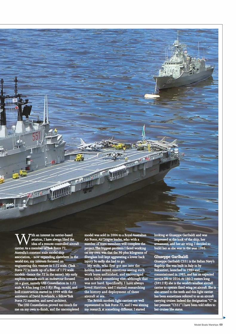
Model Boats Warships 69
With an interest in carrier-based ith an interest in carrier-based aviation, I have always liked the aviation, I have always liked the idea of a remote controlled aircraft idea of a remote controlled aircraft
carrier. As a member of Task Force 72, carrier. As a member of Task Force 72, Australia’s constant scale model ship Australia’s constant scale model ship association, - now expanding elsewhere in the association, - now expanding elsewhere in the world too, my interests focussed on world too, my interests focussed on engineering this venture in 1:72 scale. (Task engineering this venture in 1:72 scale. (Task Force 72 is made up of a fl eet of 1:72 scale Force 72 is made up of a fl eet of 1:72 scale models –hence the 72 in the name). My early models –hence the 72 in the name). My early exploits towards such an endeavour focused exploits towards such an endeavour focused on a giant, namely USS Constellation in 1:72 on a giant, namely USS Constellation in 1:72 scale. 4.43m long (14.5 ft)! Plug, mould, and scale. 4.43m long (14.5 ft)! Plug, mould, and hull construction started in 1999 with the hull construction started in 1999 with the assistance of David Rowlands, a fellow Task assistance of David Rowlands, a fellow Task Force 72 member, and naval architect.Force 72 member, and naval architect.
The USS Constellation proved too much for The USS Constellation proved too much for me on my own to fi nish, and the uncompleted me on my own to fi nish, and the uncompleted
model was sold in 2004 to a Royal Australian model was sold in 2004 to a Royal Australian Air Force, Air League leader, who with a Air Force, Air League leader, who with a number of team members will complete the number of team members will complete the project. The biggest problem I faced working project. The biggest problem I faced working on my own was that the 90 plus kilograms of on my own was that the 90 plus kilograms of fi breglass hull kept aggravating a lower back fi breglass hull kept aggravating a lower back injury. So sadly she had to go.injury. So sadly she had to go.
My wife, who first got me into the My wife, who first got me into the hobby, had mixed emotions seeing such hobby, had mixed emotions seeing such work leave unfinished, and encouraged work leave unfinished, and encouraged me to build something else, although that me to build something else, although that was not hard. Specifically, I have always was not hard. Specifically, I have always loved Harriers, and I started researching loved Harriers, and I started researching the history and deployment of these the history and deployment of these aircraft at sea.aircraft at sea.
The British modern light carriers are well The British modern light carriers are well represented in Task Force 72, and I was aiming represented in Task Force 72, and I was aiming my research at something different. I started my research at something different. I started
looking at Giuseppe Garibaldi and was looking at Giuseppe Garibaldi and was impressed at the look of the ship, her impressed at the look of the ship, her armament, and her air wing. I decided to armament, and her air wing. I decided to build her as she was in the year 1995.build her as she was in the year 1995.
Giuseppe GaribaldiGiuseppe GaribaldiGiuseppe Garibaldi C551 is the Italian Navy’s Giuseppe Garibaldi C551 is the Italian Navy’s fl agship. She was built in Italy in by fl agship. She was built in Italy in by Italcantieri, launched in 1983 and Italcantieri, launched in 1983 and commissioned in 1985, and has an expected commissioned in 1985, and has an expected service life to 2016. At 180.2 meters long service life to 2016. At 180.2 meters long (591.2 ft) she is the world’s smallest aircraft (591.2 ft) she is the world’s smallest aircraft carrier to operate fi xed wing jet aircraft. She is carrier to operate fi xed wing jet aircraft. She is also armed to the teeth and this light carrier also armed to the teeth and this light carrier has been sometimes referred to as an aircraft has been sometimes referred to as an aircraft carrying cruiser. Indeed the designation “C” in carrying cruiser. Indeed the designation “C” in her pennant “C551” I have been told refers to her pennant “C551” I have been told refers to her cruiser like status.her cruiser like status.
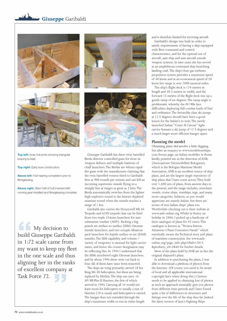
“ My decision to build Giuseppe Garibaldi in 1:72 scale came from my want to keep my fl eet in the one scale and thus aligning her in the ranks of excellent company at Task Force 72. ”
Top left: Inner hull joints showing triangular bracing to keel.
Top right: Early bow construction.
Above left: Hull nearing completion prior to fi breglassing.
Above right: Stern half of hull inverted with running gear installed and fi breglassing complete.
70 www.modelboats.co.uk
Giuseppe Garibaldi
and is therefore limited for servicing aircraft.Garibaldi’s design was built in order to
satisfy requirements of having a ship equipped with fl eet command and control characteristics, and for the optimal use of aircraft, anti-ship and anti-aircraft missile weapon systems. In later years she has served as an amphibious command ship launching landing craft. The ship’s four gas turbines propulsion system provides a maximum speed of 30 knots and at an economical speed of 20 knots her range is over 7000 nautical miles.
The ship’s fl ight deck is 174 metres in length and 30.5 metres in width, and the forward 15 metres of the fl ight deck rise up a gentle ramp of six degrees. The ramp angle is problematic whereby the AV/8Bs face diffi culties deploying full combat loads of fuel and ordinance. The Invincible class ski-jumps at 12.5 degrees should have been a good lesson for the Italian’s to note. The newly launched Italian “Conte di Cavour” light carrier features a ski jump of 12.5 degrees and a much larger more effi cient hanger space.
Planning the modelObtaining plans did involve a little digging, but after an enquiry to www.modelwarships.com forum page, an Italian modeller in Rome kindly pointed me in the direction of ANB, (Associazione Navimodellisti Bolognesi), which is the Bologna Maritime Model Association. ANB is an excellent source of ship plans, and are the largest single repository of ship plans that I have come across. They hold over 1,600 sets of plans, from ancient days to the present, and the range includes, merchant vessels, cruise ships, warships, tugs, and many more categories. Subjects, as you would appreciate are mainly Italian, but there are scores of non Italian ships’ plans too. Worthwhile checking out is their website at www.anb-online.org. Whilst in Venice on holiday in 2004, I picked up a hardcopy of their catalogue of plans for 45 euros. This catalogue is known as “Tecnica Estoria Attraverso I Piani Costruttivi Navali” which essentially means the Technical story and plans of maritime construction. See www.anb-online.org/page_info php?cPath=2015&products_id=3840 for further details.
Most of the plans held by ANB are in fact the original shipyard’s plans.
In addition to purchasing the plans, I was able to download a plethora of photos from the Internet. (Of course you need to be aware of local and all applicable international copyright laws when doing this.) Caution needs to be applied in obtaining lots of photos as such an approach invariably gets you photos from different time periods and I have found quite a bit of differences in structures and fi ttings over the life of the ship thus far. Indeed the latest version of Jane’s Fighting Ships
Giuseppe Garibaldi has three twin barrelled Breda director controlled guns for close-in weapon defence and multiple batteries of chaff launchers. The Bredas are 40mm rapid-fi re guns with the manufacturer claiming that the twin barrelled version fi tted to Garibaldi fi res at 900 rounds per minute and can kill an incoming supersonic missile fl ying in a straight line at ranges as great as 3 kms. The Breda automatically switches from the lighter high explosive round to the heavier depleted uranium round when the missile reaches a range of 1 km.
Garibaldi also carries the Honeywell Mk 46 Torpedo and A290 torpedo that can be fi red from two triple 324mm launchers for anti-submarine warfare (ASW). Packing a big punch are surface-to-surface (SSM) Ottomat missile launchers, and two octuple Albatross pack launchers for Aspide surface-to-air (SAM) missiles. The SSM capability and volume / variety of weaponry is unusual for light carrier status, and hence the cruiser designation may be refl ecting this. In 1994 I understand that the SSMs numbered eight Ottomat launchers, and by about 1996 these were cut back to four. All of them have since been removed.
The ships air wing primarily carried 18 Sea King SH-3D helicopters, but these are being replaced by Merlins. The ship can carry 16 AV/8B Plus II Harriers, the fi rst of which arrived in 1994. Carrying all 16 would not leave room for helicopters so usually a mix of Harriers (10 is usual) and helicopters is carried. The hangar does not extended through the ship’s maximum width or run its entire length
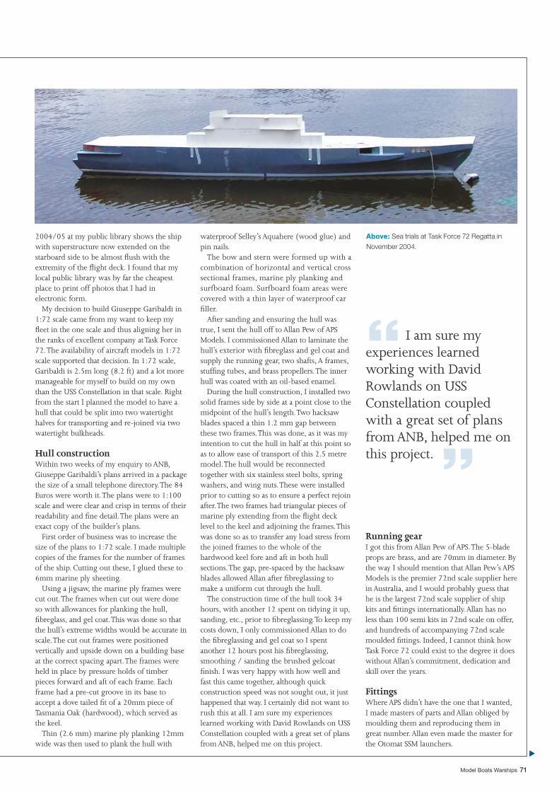
“ I am sure my experiences learned working with David Rowlands on USS Constellation coupled with a great set of plans from ANB, helped me on this project. ”
Above: Sea trials at Task Force 72 Regatta in November 2004.
Model Boats Warships 71
2004/05 at my public library shows the ship with superstructure now extended on the starboard side to be almost fl ush with the extremity of the fl ight deck. I found that my local public library was by far the cheapest place to print off photos that I had in electronic form.
My decision to build Giuseppe Garibaldi in 1:72 scale came from my want to keep my fl eet in the one scale and thus aligning her in the ranks of excellent company at Task Force 72. The availability of aircraft models in 1:72 scale supported that decision. In 1:72 scale, Garibaldi is 2.5m long (8.2 ft) and a lot more manageable for myself to build on my own than the USS Constellation in that scale. Right from the start I planned the model to have a hull that could be split into two watertight halves for transporting and re-joined via two watertight bulkheads.
Hull constructionWithin two weeks of my enquiry to ANB, Giuseppe Garibaldi’s plans arrived in a package the size of a small telephone directory. The 84 Euros were worth it. The plans were to 1:100 scale and were clear and crisp in terms of their readability and fi ne detail. The plans were an exact copy of the builder’s plans.
First order of business was to increase the size of the plans to 1:72 scale. I made multiple copies of the frames for the number of frames of the ship. Cutting out these, I glued these to 6mm marine ply sheeting.
Using a jigsaw, the marine ply frames were cut out. The frames when cut out were done so with allowances for planking the hull, fi breglass, and gel coat. This was done so that the hull’s extreme widths would be accurate in scale. The cut out frames were positioned vertically and upside down on a building base at the correct spacing apart. The frames were held in place by pressure holds of timber pieces forward and aft of each frame. Each frame had a pre-cut groove in its base to accept a dove tailed fi t of a 20mm piece of Tasmania Oak (hardwood), which served as the keel.
Thin (2.6 mm) marine ply planking 12mm wide was then used to plank the hull with
waterproof Selley’s Aquahere (wood glue) and pin nails.
The bow and stern were formed up with a combination of horizontal and vertical cross sectional frames, marine ply planking and surfboard foam. Surfboard foam areas were covered with a thin layer of waterproof car fi ller.
After sanding and ensuring the hull was true, I sent the hull off to Allan Pew of APS Models. I commissioned Allan to laminate the hull’s exterior with fi breglass and gel coat and supply the running gear, two shafts, A frames, stuffi ng tubes, and brass propellers. The inner hull was coated with an oil-based enamel.
During the hull construction, I installed two solid frames side by side at a point close to the midpoint of the hull’s length. Two hacksaw blades spaced a thin 1.2 mm gap between these two frames. This was done, as it was my intention to cut the hull in half at this point so as to allow ease of transport of this 2.5 metre model. The hull would be reconnected together with six stainless steel bolts, spring washers, and wing nuts. These were installed prior to cutting so as to ensure a perfect rejoin after. The two frames had triangular pieces of marine ply extending from the fl ight deck level to the keel and adjoining the frames. This was done so as to transfer any load stress from the joined frames to the whole of the hardwood keel fore and aft in both hull sections. The gap, pre-spaced by the hacksaw blades allowed Allan after fi breglassing to make a uniform cut through the hull.
The construction time of the hull took 34 hours, with another 12 spent on tidying it up, sanding, etc., prior to fi breglassing. To keep my costs down, I only commissioned Allan to do the fi breglassing and gel coat so I spent another 12 hours post his fi breglassing, smoothing / sanding the brushed gelcoat fi nish. I was very happy with how well and fast this came together, although quick construction speed was not sought out, it just happened that way. I certainly did not want to rush this at all. I am sure my experiences learned working with David Rowlands on USS Constellation coupled with a great set of plans from ANB, helped me on this project.
Running gearI got this from Allan Pew of APS. The 5-blade props are brass, and are 70mm in diameter. By the way I should mention that Allan Pew’s APS Models is the premier 72nd scale supplier here in Australia, and I would probably guess that he is the largest 72nd scale supplier of ship kits and fi ttings internationally. Allan has no less than 100 semi kits in 72nd scale on offer, and hundreds of accompanying 72nd scale moulded fi ttings. Indeed, I cannot think how Task Force 72 could exist to the degree it does without Allan’s commitment, dedication and skill over the years.
FittingsWhere APS didn’t have the one that I wanted, I made masters of parts and Allan obliged by moulding them and reproducing them in great number. Allan even made the master for the Otomat SSM launchers.
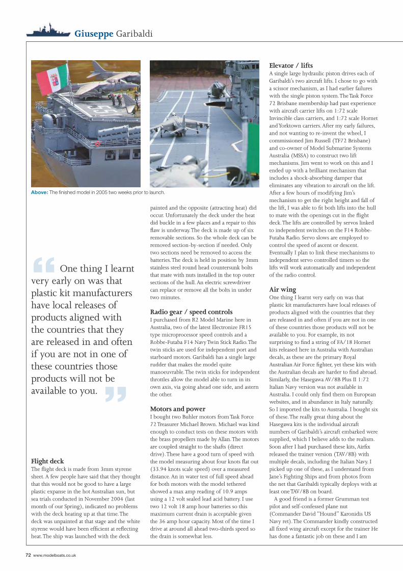
Above: The fi nished model in 2005 two weeks prior to launch.
“ One thing I learnt very early on was that plastic kit manufacturers have local releases of products aligned with the countries that they are released in and often if you are not in one of these countries those products will not be available to you. ”
72 www.modelboats.co.uk
Elevator / liftsA single large hydraulic piston drives each of Garibaldi’s two aircraft lifts. I chose to go with a scissor mechanism, as I had earlier failures with the single piston system. The Task Force 72 Brisbane membership had past experience with aircraft carrier lifts on 1:72 scale Invincible class carriers, and 1:72 scale Hornet and Yorktown carriers. After my early failures, and not wanting to re-invent the wheel, I commissioned Jim Russell (TF72 Brisbane) and co-owner of Model Submarine Systems Australia (MSSA) to construct two lift mechanisms. Jim went to work on this and I ended up with a brilliant mechanism that includes a shock-absorbing damper that eliminates any vibration to aircraft on the lift. After a few hours of modifying Jim’s mechanism to get the right height and fall of the lift, I was able to fi t both lifts into the hull to mate with the openings cut in the fl ight deck. The lifts are controlled by servos linked to independent switches on the F14 Robbe-Futaba Radio. Servo slows are employed to control the speed of ascent or descent. Eventually I plan to link these mechanisms to independent servo controlled timers so the lifts will work automatically and independent of the radio control.
Air wingOne thing I learnt very early on was that plastic kit manufacturers have local releases of products aligned with the countries that they are released in and often if you are not in one of these countries those products will not be available to you. For example, its not surprising to fi nd a string of FA/18 Hornet kits released here in Australia with Australian decals, as these are the primary Royal Australian Air Force fi ghter, yet these kits with the Australian decals are harder to fi nd abroad. Similarly, the Hasegawa AV/8B Plus II 1:72 Italian Navy version was not available in Australia. I could only fi nd them on European websites, and in abundance in Italy naturally. So I imported the kits to Australia. I bought six of these. The really great thing about the Hasegawa kits is the individual aircraft numbers of Garibaldi’s aircraft embarked were supplied, which I believe adds to the realism. Soon after I had purchased these kits, Airfi x released the trainer version (TAV/8B) with multiple decals, including the Italian Navy. I picked up one of these, as I understand from Jane’s Fighting Ships and from photos from the net that Garibaldi typically deploys with at least one TAV/8B on board.
A good friend is a former Grumman test pilot and self-confessed plane nut (Commander David “Hound” Karonidis US Navy ret). The Commander kindly constructed all fi xed wing aircraft except for the trainer He has done a fantastic job on these and I am
painted and the opposite (attracting heat) did occur. Unfortunately the deck under the heat did buckle in a few places and a repair to this fl aw is underway. The deck is made up of six removable sections. So the whole deck can be removed section-by-section if needed. Only two sections need be removed to access the batteries. The deck is held in position by 3mm stainless steel round head countersunk bolts that mate with nuts installed in the top outer sections of the hull. An electric screwdriver can replace or remove all the bolts in under two minutes.
Radio gear / speed controlsI purchased from R2 Model Marine here in Australia, two of the latest Electronize FR15 type microprocessor speed controls and a Robbe-Futaba F14 Navy Twin Stick Radio. The twin sticks are used for independent port and starboard motors. Garibaldi has a single large rudder that makes the model quite manoeuvrable. The twin sticks for independent throttles allow the model able to turn in its own axis, via going ahead one side, and astern the other.
Motors and powerI bought two Buhler motors from Task Force 72 Treasurer Michael Brown. Michael was kind enough to conduct tests on these motors with the brass propellers made by Allan. The motors are coupled straight to the shafts (direct drive). These have a good turn of speed with the model measuring about four knots fl at out (33.94 knots scale speed) over a measured distance. An in water test of full speed ahead for both motors with the model tethered showed a max amp reading of 10.9 amps using a 12 volt sealed lead acid battery. I use two 12 volt 18 amp hour batteries so this maximum current drain is acceptable given the 36 amp hour capacity. Most of the time I drive at around all ahead two-thirds speed so the drain is somewhat less.
Flight deckThe fl ight deck is made from 3mm styrene sheet. A few people have said that they thought that this would not be good to have a large plastic expanse in the hot Australian sun, but sea trials conducted in November 2004 (last month of our Spring), indicated no problems with the deck heating up at that time. The deck was unpainted at that stage and the white styrene would have been effi cient at refl ecting heat. The ship was launched with the deck
Giuseppe Garibaldi
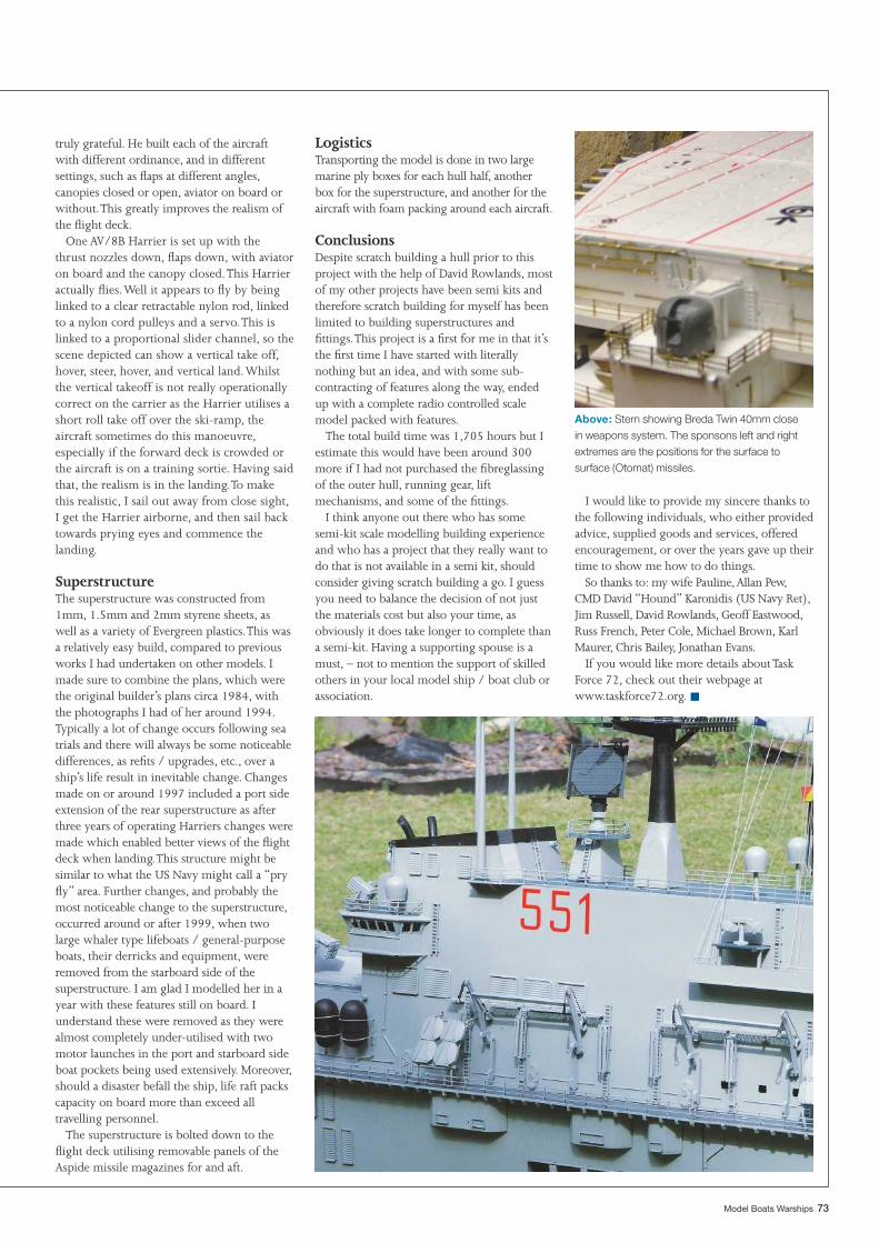
Above: Stern showing Breda Twin 40mm close in weapons system. The sponsons left and right extremes are the positions for the surface to surface (Otomat) missiles.
Model Boats Warships 73
truly grateful. He built each of the aircraft with different ordinance, and in different settings, such as fl aps at different angles, canopies closed or open, aviator on board or without. This greatly improves the realism of the fl ight deck.
One AV/8B Harrier is set up with the thrust nozzles down, fl aps down, with aviator on board and the canopy closed. This Harrier actually fl ies. Well it appears to fl y by being linked to a clear retractable nylon rod, linked to a nylon cord pulleys and a servo. This is linked to a proportional slider channel, so the scene depicted can show a vertical take off, hover, steer, hover, and vertical land. Whilst the vertical takeoff is not really operationally correct on the carrier as the Harrier utilises a short roll take off over the ski-ramp, the aircraft sometimes do this manoeuvre, especially if the forward deck is crowded or the aircraft is on a training sortie. Having said that, the realism is in the landing. To make this realistic, I sail out away from close sight, I get the Harrier airborne, and then sail back towards prying eyes and commence the landing.
SuperstructureThe superstructure was constructed from 1mm, 1.5mm and 2mm styrene sheets, as well as a variety of Evergreen plastics. This was a relatively easy build, compared to previous works I had undertaken on other models. I made sure to combine the plans, which were the original builder’s plans circa 1984, with the photographs I had of her around 1994. Typically a lot of change occurs following sea trials and there will always be some noticeable differences, as refi ts / upgrades, etc., over a ship’s life result in inevitable change. Changes made on or around 1997 included a port side extension of the rear superstructure as after three years of operating Harriers changes were made which enabled better views of the fl ight deck when landing. This structure might be similar to what the US Navy might call a “pry fl y” area. Further changes, and probably the most noticeable change to the superstructure, occurred around or after 1999, when two large whaler type lifeboats / general-purpose boats, their derricks and equipment, were removed from the starboard side of the superstructure. I am glad I modelled her in a year with these features still on board. I understand these were removed as they were almost completely under-utilised with two motor launches in the port and starboard side boat pockets being used extensively. Moreover, should a disaster befall the ship, life raft packs capacity on board more than exceed all travelling personnel.
The superstructure is bolted down to the fl ight deck utilising removable panels of the Aspide missile magazines for and aft.
LogisticsTransporting the model is done in two large marine ply boxes for each hull half, another box for the superstructure, and another for the aircraft with foam packing around each aircraft.
ConclusionsDespite scratch building a hull prior to this project with the help of David Rowlands, most of my other projects have been semi kits and therefore scratch building for myself has been limited to building superstructures and fi ttings. This project is a fi rst for me in that it’s the fi rst time I have started with literally nothing but an idea, and with some sub-contracting of features along the way, ended up with a complete radio controlled scale model packed with features.
The total build time was 1,705 hours but I estimate this would have been around 300 more if I had not purchased the fi breglassing of the outer hull, running gear, lift mechanisms, and some of the fi ttings.
I think anyone out there who has some semi-kit scale modelling building experience and who has a project that they really want to do that is not available in a semi kit, should consider giving scratch building a go. I guess you need to balance the decision of not just the materials cost but also your time, as obviously it does take longer to complete than a semi-kit. Having a supporting spouse is a must, – not to mention the support of skilled others in your local model ship / boat club or association.
I would like to provide my sincere thanks to the following individuals, who either provided advice, supplied goods and services, offered encouragement, or over the years gave up their time to show me how to do things.
So thanks to: my wife Pauline, Allan Pew, CMD David “Hound” Karonidis (US Navy Ret), Jim Russell, David Rowlands, Geoff Eastwood, Russ French, Peter Cole, Michael Brown, Karl Maurer, Chris Bailey, Jonathan Evans.
If you would like more details about Task Force 72, check out their webpage at www.taskforce72.org. ■
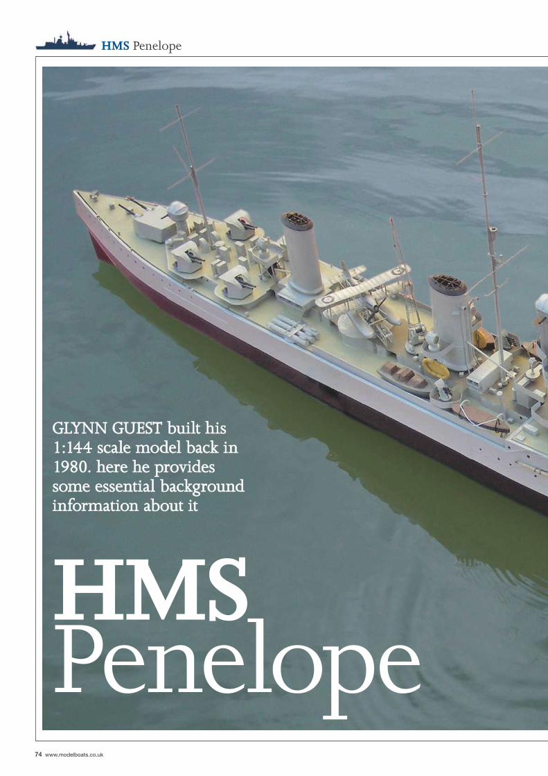
74 www.modelboats.co.uk
HMS Penelope
HMS Penelope
GLYNN GUEST built his GLYNN GUEST built his 1:144 scale model back in 1:144 scale model back in 1980. here he provides 1980. here he provides some essential background some essential background information about itinformation about it
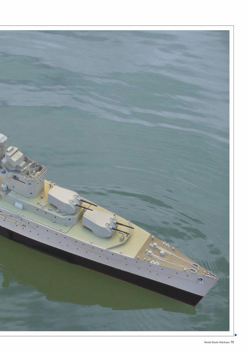
Model Boats Warships 75
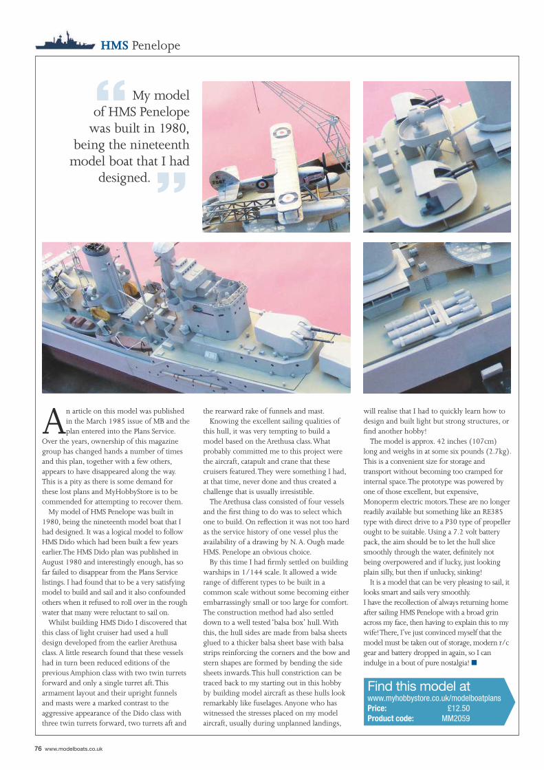
“ My model of HMS Penelope
was built in 1980, being the nineteenth
model boat that I had designed. ”
■
76 www.modelboats.co.uk
Find this model atwww.myhobbystore.co.uk/modelboatplansPrice: £12.50Product code: MM2059
HMS Penelope
An article on this model was published in the March 1985 issue of MB and the plan entered into the Plans Service.
Over the years, ownership of this magazine group has changed hands a number of times and this plan, together with a few others, appears to have disappeared along the way. This is a pity as there is some demand for these lost plans and MyHobbyStore is to be commended for attempting to recover them.
My model of HMS Penelope was built in 1980, being the nineteenth model boat that I had designed. It was a logical model to follow HMS Dido which had been built a few years earlier. The HMS Dido plan was published in August 1980 and interestingly enough, has so far failed to disappear from the Plans Service listings. I had found that to be a very satisfying model to build and sail and it also confounded others when it refused to roll over in the rough water that many were reluctant to sail on.
Whilst building HMS Dido I discovered that this class of light cruiser had used a hull design developed from the earlier Arethusa class. A little research found that these vessels had in turn been reduced editions of the previous Amphion class with two twin turrets forward and only a single turret aft. This armament layout and their upright funnels and masts were a marked contrast to the aggressive appearance of the Dido class with three twin turrets forward, two turrets aft and
the rearward rake of funnels and mast.Knowing the excellent sailing qualities of
this hull, it was very tempting to build a model based on the Arethusa class. What probably committed me to this project were the aircraft, catapult and crane that these cruisers featured. They were something I had, at that time, never done and thus created a challenge that is usually irresistible.
The Arethusa class consisted of four vessels and the fi rst thing to do was to select which one to build. On refl ection it was not too hard as the service history of one vessel plus the availability of a drawing by N. A. Ough made HMS. Penelope an obvious choice.
By this time I had fi rmly settled on building warships in 1/144 scale. It allowed a wide range of different types to be built in a common scale without some becoming either embarrassingly small or too large for comfort. The construction method had also settled down to a well tested ‘balsa box’ hull. With this, the hull sides are made from balsa sheets glued to a thicker balsa sheet base with balsa strips reinforcing the corners and the bow and stern shapes are formed by bending the side sheets inwards. This hull constriction can be traced back to my starting out in this hobby by building model aircraft as these hulls look remarkably like fuselages. Anyone who has witnessed the stresses placed on my model aircraft, usually during unplanned landings,
will realise that I had to quickly learn how to design and built light but strong structures, or fi nd another hobby!
The model is approx. 42 inches (107cm) long and weighs in at some six pounds (2.7kg). This is a convenient size for storage and transport without becoming too cramped for internal space. The prototype was powered by one of those excellent, but expensive, Monoperm electric motors. These are no longer readily available but something like an RE385 type with direct drive to a P30 type of propeller ought to be suitable. Using a 7.2 volt battery pack, the aim should be to let the hull slice smoothly through the water, defi nitely not being overpowered and if lucky, just looking plain silly, but then if unlucky, sinking!
It is a model that can be very pleasing to sail, it looks smart and sails very smoothly. I have the recollection of always returning home after sailing HMS Penelope with a broad grin across my face, then having to explain this to my wife! There, I’ve just convinced myself that the model must be taken out of storage, modern r/c gear and battery dropped in again, so I can indulge in a bout of pure nostalgia!

Claim your FREE Issue of Model Boats Magazine* today!
There are no obligations or catches. Simply call: 0845 286 4635** quoting MBWSFREE0514 to
claim your free copy now*
Model Boats has brought benchmark levels of in-depth writing and quality photography to the hobby. Each issue has extensive kit and model reviews, informative features, show reports, club news, new items for the modeller and regular expert columns from a number of highly regarded contributors. Within alternate issues you’ll find a high-quality free plan along with an accompanying build article. Model Boats covers all areas of this absorbing hobby. Whether your interest is in Tugs, Lifeboats, Warships, Sailing Craft, Model Yachting or Offshore Racing, (just to name a few!), you will find something of interest within its pages.
Terms & Conditions: Offer ends 30th August 2014 *This offer is available for UK delivery addresses only and is subject to availability. When you respond you will be offered the chance to take out a trial subscription – there is no obligation to do so. Your free issue will be the next available issue posted to you within 6 weeks of your phone call. This offer is not available to existing Model Boats subscribers and may not be used in conjunction with any other offer. 1 free issue only per household/caller. **Lines are open weekdays 8am to 8:30pm and weekends 10am to 4pm. Calls will cost 5p per minute from a BT landline. Calls from mobiles and other providers may vary.
Offer ends 30th August 2014
SPECIAL OFFER
for Model Boat Warships Readers!
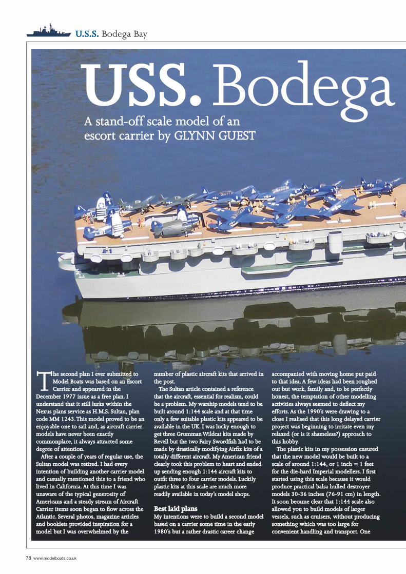
78 www.modelboats.co.uk
U.S.S. Bodega Bay
USS. Bodega A stand-off scale model of an A stand-off scale model of an escort carrier by GLYNN GUESTescort carrier by GLYNN GUEST
The second plan I ever submitted to he second plan I ever submitted to Model Boats was based on an Escort Model Boats was based on an Escort Carrier and appeared in the Carrier and appeared in the
December 1977 issue as a free plan. I December 1977 issue as a free plan. I understand that it still lurks within the understand that it still lurks within the Nexus plans service as H.M.S. Sultan, plan Nexus plans service as H.M.S. Sultan, plan code MM 1243. This model proved to be an code MM 1243. This model proved to be an enjoyable one to sail and, as aircraft carrier enjoyable one to sail and, as aircraft carrier models have never been exactly models have never been exactly commonplace, it always attracted some commonplace, it always attracted some degree of attention.degree of attention.
After a couple of years of regular use, the After a couple of years of regular use, the Sultan model was retired. I had every Sultan model was retired. I had every intention of building another carrier model intention of building another carrier model and casually mentioned this to a friend who and casually mentioned this to a friend who lived in California. At this time I was lived in California. At this time I was unaware of the typical generosity of unaware of the typical generosity of Americans and a steady stream of Aircraft Americans and a steady stream of Aircraft Carrier items soon began to fl ow across the Carrier items soon began to fl ow across the Atlantic. Several photos, magazine articles Atlantic. Several photos, magazine articles and booklets provided inspiration for a and booklets provided inspiration for a model but I was overwhelmed by the model but I was overwhelmed by the
number of plastic aircraft kits that arrived in number of plastic aircraft kits that arrived in the post.the post.
The Sultan article contained a reference The Sultan article contained a reference that the aircraft, essential for realism, could that the aircraft, essential for realism, could be a problem. My warship models tend to be be a problem. My warship models tend to be built around 1:144 scale and at that time built around 1:144 scale and at that time only a few suitable plastic kits appeared to be only a few suitable plastic kits appeared to be available in the UK. I was lucky enough to available in the UK. I was lucky enough to get three Grumman Wildcat kits made by get three Grumman Wildcat kits made by Revell but the two Fairy Swordfi sh had to be Revell but the two Fairy Swordfi sh had to be made by drastically modifying Airfi x kits of a made by drastically modifying Airfi x kits of a totally different aircraft. My American friend totally different aircraft. My American friend clearly took this problem to heart and ended clearly took this problem to heart and ended up sending enough 1:144 aircraft kits to up sending enough 1:144 aircraft kits to outfi t three to four carrier models. Luckily outfi t three to four carrier models. Luckily plastic kits at this scale are much more plastic kits at this scale are much more readily available in today’s model shops.readily available in today’s model shops.
Best laid plansBest laid plansMy intentions were to build a second model My intentions were to build a second model based on a carrier some time in the early based on a carrier some time in the early 1980’s but a rather drastic career change 1980’s but a rather drastic career change
accompanied with moving home put paid accompanied with moving home put paid to that idea. A few ideas had been roughed to that idea. A few ideas had been roughed out but work, family and, to be perfectly out but work, family and, to be perfectly honest, the temptation of other modelling honest, the temptation of other modelling activities always seemed to defl ect my activities always seemed to defl ect my efforts. As the 1990’s were drawing to a efforts. As the 1990’s were drawing to a close I realised that this long delayed carrier close I realised that this long delayed carrier project was beginning to irritate even my project was beginning to irritate even my relaxed (or is it shameless?) approach to relaxed (or is it shameless?) approach to this hobby.this hobby.
The plastic kits in my possession ensured The plastic kits in my possession ensured that the new model would be built to a that the new model would be built to a scale of around 1:144, or 1 inch = 1 feet scale of around 1:144, or 1 inch = 1 feet for the die-hard Imperial modellers. I fi rst for the die-hard Imperial modellers. I fi rst started using this scale because it would started using this scale because it would produce practical balsa hulled destroyer produce practical balsa hulled destroyer models 30-36 inches (76-91 cm) in length. models 30-36 inches (76-91 cm) in length. It soon became clear that 1:144 scale also It soon became clear that 1:144 scale also allowed you to build models of larger allowed you to build models of larger vessels, such as cruisers, without producing vessels, such as cruisers, without producing something which was too large for something which was too large for convenient handling and transport. One convenient handling and transport. One
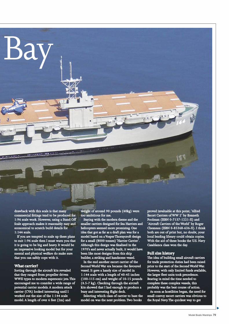
Model Boats Warships 79
Bay
drawback with this scale is that many drawback with this scale is that many commercial fi ttings tend to be produced for commercial fi ttings tend to be produced for 1:96 scale work. However, using a Stand Off 1:96 scale work. However, using a Stand Off Scale approach makes it reasonably easy and Scale approach makes it reasonably easy and economical to scratch build details for economical to scratch build details for 1:144 scale.1:144 scale.
If you are tempted to scale up these plans If you are tempted to scale up these plans to suit 1:96 scale then I must warn you that to suit 1:96 scale then I must warn you that it is going to be big and heavy. It would be it is going to be big and heavy. It would be an impressive looking model but for your an impressive looking model but for your mental and physical welfare do make sure mental and physical welfare do make sure that you can safely cope with it.that you can safely cope with it.
What carrier?What carrier?Sorting through the aircraft kits revealed Sorting through the aircraft kits revealed that they ranged from propeller driven that they ranged from propeller driven WWII types to modern supersonic jets. This WWII types to modern supersonic jets. This encouraged me to consider a wide range of encouraged me to consider a wide range of potential carrier models. A modern attack potential carrier models. A modern attack carrier (CVA) looked interesting until I carrier (CVA) looked interesting until I worked out the size of the 1:144 scale worked out the size of the 1:144 scale model. A length of over 6 feet (2m) and model. A length of over 6 feet (2m) and
weight of around 90 pounds (40kg) were weight of around 90 pounds (40kg) were too ambitious for me.too ambitious for me.
Staying with the modern theme and the Staying with the modern theme and the smaller carriers designed for Sea Harriers and smaller carriers designed for Sea Harriers and helicopters seemed more promising. One helicopters seemed more promising. One idea that got as far as a draft plan was for a idea that got as far as a draft plan was for a model based on a Vosper Thornycroft design model based on a Vosper Thornycroft design for a small (8000 tonnes) ‘Harrier Carrier’. for a small (8000 tonnes) ‘Harrier Carrier’. Although this design was fi nalised in the Although this design was fi nalised in the 1970’s and never actually built, it would have 1970’s and never actually built, it would have been like most designs from this ship been like most designs from this ship builder, a striking and handsome vessel.builder, a striking and handsome vessel.
In the end another escort carrier of the In the end another escort carrier of the Second World War era became the favoured Second World War era became the favoured vessel. It gave a handy size of model in vessel. It gave a handy size of model in 1:144 scale with a length of 40-45 inches 1:144 scale with a length of 40-45 inches (100-115 cm) and weight of 10-15 pounds (100-115 cm) and weight of 10-15 pounds (4.5-7 kg). Checking through the aircraft (4.5-7 kg). Checking through the aircraft kits showed that I had enough to produce a kits showed that I had enough to produce a busy and interesting fl ight deck.busy and interesting fl ight deck.
Selecting which class of carrier to base the Selecting which class of carrier to base the model on was the next problem. Two books model on was the next problem. Two books
proved invaluable at this point, ‘Allied proved invaluable at this point, ‘Allied Escort Carriers of WW 2’ by Kenneth Escort Carriers of WW 2’ by Kenneth Poolman (ISBN 0-7137-1221-X) and Poolman (ISBN 0-7137-1221-X) and ‘Aircraft Carriers of the World’ by Roger ‘Aircraft Carriers of the World’ by Roger Chesneau (ISBN 0-85368-636-X). I think Chesneau (ISBN 0-85368-636-X). I think both are out of print but, no doubt, your both are out of print but, no doubt, your local lending library could obtain copies. local lending library could obtain copies. With the aid of these books the U.S. Navy With the aid of these books the U.S. Navy Casablanca class won the day.Casablanca class won the day.
Full size historyFull size historyThe idea of building small aircraft carriers The idea of building small aircraft carriers for trade protection duties had been raised for trade protection duties had been raised prior to the start of the Second World War. prior to the start of the Second World War. However, with only limited funds available, However, with only limited funds available, the larger fl eet units took precedence. the larger fl eet units took precedence. Bearing in mind the time needed to Bearing in mind the time needed to complete these complex vessels, this complete these complex vessels, this probably was the best course of action.probably was the best course of action.
As soon as hostilities began, the need for As soon as hostilities began, the need for small convoy escort carriers was obvious to small convoy escort carriers was obvious to the Royal Navy. The quickest way to getthe Royal Navy. The quickest way to get
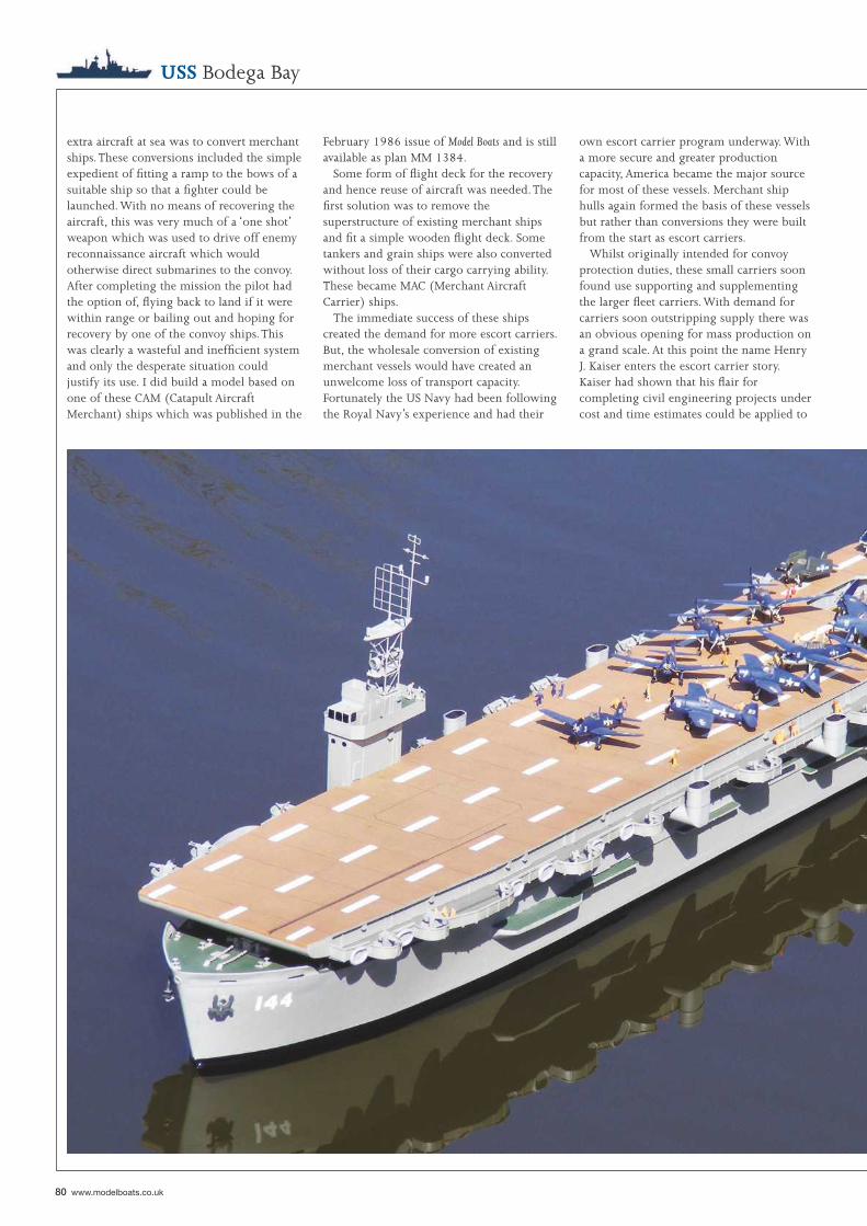
80 www.modelboats.co.uk
extra aircraft at sea was to convert merchant ships. These conversions included the simple expedient of fi tting a ramp to the bows of a suitable ship so that a fi ghter could be launched. With no means of recovering the aircraft, this was very much of a ‘one shot’ weapon which was used to drive off enemy reconnaissance aircraft which would otherwise direct submarines to the convoy. After completing the mission the pilot had the option of, fl ying back to land if it were within range or bailing out and hoping for recovery by one of the convoy ships. This was clearly a wasteful and ineffi cient system and only the desperate situation could justify its use. I did build a model based on one of these CAM (Catapult Aircraft Merchant) ships which was published in the
USS Bodega Bay
February 1986 issue of Model Boats and is still available as plan MM 1384.
Some form of fl ight deck for the recovery and hence reuse of aircraft was needed. The fi rst solution was to remove the superstructure of existing merchant ships and fi t a simple wooden fl ight deck. Some tankers and grain ships were also converted without loss of their cargo carrying ability. These became MAC (Merchant Aircraft Carrier) ships.
The immediate success of these ships created the demand for more escort carriers. But, the wholesale conversion of existing merchant vessels would have created an unwelcome loss of transport capacity. Fortunately the US Navy had been following the Royal Navy’s experience and had their
own escort carrier program underway. With a more secure and greater production capacity, America became the major source for most of these vessels. Merchant ship hulls again formed the basis of these vessels but rather than conversions they were built from the start as escort carriers.
Whilst originally intended for convoy protection duties, these small carriers soon found use supporting and supplementing the larger fl eet carriers. With demand for carriers soon outstripping supply there was an obvious opening for mass production on a grand scale. At this point the name Henry J. Kaiser enters the escort carrier story. Kaiser had shown that his fl air for completing civil engineering projects under cost and time estimates could be applied to
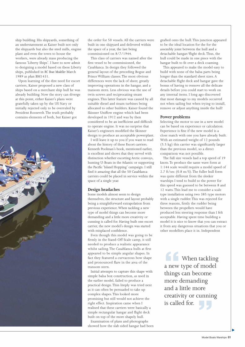
“When tackling a new type of model things can become more demanding and a little more creativity or cunning is called for. ”
Model Boats Warships 81
ship building. His shipyards, something of an understatement as Kaiser built not only the shipyards but also the steel mills, engine plant and even the town to house the workers, were already mass producing the famous ‘Liberty Ships’. I have to now admit to designing a model based on these Liberty ships, published in RC Boat Modeller March 1989 as plan BM1431.
Upon learning of the dire need for escort carriers, Kaiser proposed a new class of ships based on a merchant ship hull he was already building. Now the story can diverge at this point, either Kaiser’s plans were gratefully taken up by the US Navy or initially rejected only to be overruled by President Roosevelt. The truth probably contains elements of both, but Kaiser got
the order for 50 vessels. All the carriers were built in one shipyard and delivered within the space of a year, the last being commissioned on 8/7/1944.
This class of carriers was named after the fi rst vessel to be commissioned, the Casablanca. In design they followed the general layout of the preceding Bogue and Prince William classes. The most obvious differences were the lack of sheer, greatly improving operations in the hangar, and a transom stern. Less obvious was the use of twin screws and reciprocating steam engines. This latter feature was caused by all suitable diesel and steam turbines being allocated to other builders. Kaiser found the Skinner Unifl ow engine which had been developed in 1912 and was by then considered to be an ineffi cient and diffi cult to operate engine. It was no surprise that Kaiser’s engineers modifi ed the Skinner design to produce an acceptable powerplant.
I will leave it up to you if you want to read about the history of these Escort carriers. Kenneth Poolman’s book, mentioned earlier, is excellent and shows that they served with distinction whether escorting Arctic convoys, hunting U-Boats in the Atlantic or supporting the Pacifi c ‘Island Hopping’ campaign. I still fi nd it amazing that all the 50 Casablanca carriers could be placed in service within the space of a single year.
Design headachesSome models almost seem to design themselves, the structure and layout probably being a straightforward extrapolation from previous experience. When tackling a new type of model things can become more demanding and a little more creativity or cunning is called for. Having built one escort carrier, the new model’s design was started with misplaced confi dence.
Even though this model was going to be fi rmly in the Stand-Off Scale camp, it still needed to produce a realistic appearance whilst sailing. The Casablanca hulls at fi rst appeared to be simple angular shapes. In fact they featured a curvaceous bow shape and pronounced fl are in the area of the transom stern.
Initial attempts to capture this shape with simple balsa box construction, as used in the earlier model, failed to produce a practical design. Thin liteply was tried next as it can often be persuaded to take up complex shapes. This looked more promising but still would not achieve the right effect. Inspiration came when I realised that these carriers were basically a simple rectangular hangar and fl ight deck built on top of the more shapely hull.
Examination of plans and photographs showed how the slab sided hangar had been
grafted onto the hull. This junction appeared to be the ideal location for the for the assembly joint between the hull and a detachable hangar/fl ight deck. Thus, the hull could be made in one piece with the hangar built to fi t over a deck coaming.
This appeared to make the model easy to build with none of the balsa parts being longer than the standard sheet sizes. A detachable fl ight deck and hangar gave the bonus of having to remove all the delicate details before you could start to work on any internal items. I long ago discovered that most damage to my models occurred not when sailing but when trying to install, remove or adjust anything inside the hull!
Power problemsSelecting the motor to use in a new model can be based on experience or calculation. Experience is fi ne if the new model is a close match with one you have already built. With an estimated weight of 12 pounds (5.5 kg) this carrier was signifi cantly larger than the previous model, so a direct comparison was not possible.
The full size vessels had a top speed of 19 knots. To produce the same wave form at 1:144 scale would require a model speed of 2.7 ft/sec (0.8 m/S). The fuller hull form was quite different from the sleeker warships I tend to build so the power for this speed was guessed to be between 8 and 12 watts. This lead me to consider a scale type installation using two 385 type motors with a single rudder. This was rejected for three reasons, fi rstly the rudder being between the propellers would have produced less steering response than I felt acceptable. Having spent time building a model it is nice to know that you can extract it from any dangerous situations that you or other modellers place it in. Independent
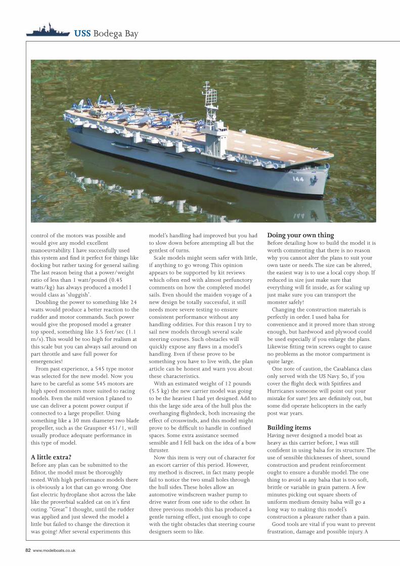
82 www.modelboats.co.uk
USS Bodega Bay
control of the motors was possible and would give any model excellent manoeuvrability. I have successfully used this system and fi nd it perfect for things like docking but rather taxing for general sailing. The last reason being that a power/weight ratio of less than 1 watt/pound (0.45 watts/kg) has always produced a model I would class as ‘sluggish’.
Doubling the power to something like 24 watts would produce a better reaction to the rudder and motor commands. Such power would give the proposed model a greater top speed, something like 3.5 feet/sec (1.1 m/s). This would be too high for realism at this scale but you can always sail around on part throttle and save full power for emergencies!
From past experience, a 545 type motor was selected for the new model. Now you have to be careful as some 545 motors are high speed monsters more suited to racing models. Even the mild version I planed to use can deliver a potent power output if connected to a large propeller. Using something like a 30 mm diameter two blade propeller, such as the Graupner 451/1, will usually produce adequate performance in this type of model.
A little extra?Before any plan can be submitted to the Editor, the model must be thoroughly tested. With high performance models there is obviously a lot that can go wrong. One fast electric hydroplane shot across the lake like the proverbial scalded cat on it’s fi rst outing. “Great” I thought, until the rudder was applied and just slewed the model a little but failed to change the direction it was going! After several experiments this
model’s handling had improved but you had to slow down before attempting all but the gentlest of turns.
Scale models might seem safer with little, if anything to go wrong. This opinion appears to be supported by kit reviews which often end with almost perfunctory comments on how the completed model sails. Even should the maiden voyage of a new design be totally successful, it still needs more severe testing to ensure consistent performance without any handling oddities. For this reason I try to sail new models through several scale steering courses. Such obstacles will quickly expose any fl aws in a model’s handling. Even if these prove to be something you have to live with, the plan article can be honest and warn you about these characteristics.
With an estimated weight of 12 pounds (5.5 kg) the new carrier model was going to be the heaviest I had yet designed. Add to this the large side area of the hull plus the overhanging fl ightdeck, both increasing the effect of crosswinds, and this model might prove to be diffi cult to handle in confi ned spaces. Some extra assistance seemed sensible and I fell back on the idea of a bow thruster.
Now this item is very out of character for an escort carrier of this period. However, my method is discreet, in fact many people fail to notice the two small holes through the hull sides. These holes allow an automotive windscreen washer pump to drive water from one side to the other. In three previous models this has produced a gentle turning effect, just enough to cope with the tight obstacles that steering course designers seem to like.
Doing your own thingBefore detailing how to build the model it is worth commenting that there is no reason why you cannot alter the plans to suit your own taste or needs. The size can be altered, the easiest way is to use a local copy shop. If reduced in size just make sure that everything will fi t inside, as for scaling up just make sure you can transport the monster safely!
Changing the construction materials is perfectly in order. I used balsa for convenience and it proved more than strong enough, but hardwood and plywood could be used especially if you enlarge the plans. Likewise fi tting twin screws ought to cause no problems as the motor compartment is quite large.
One note of caution, the Casablanca class only served with the US Navy. So, if you cover the fl ight deck with Spitfi res and Hurricanes someone will point out your mistake for sure! Jets are defi nitely out, but some did operate helicopters in the early post war years.
Building itemsHaving never designed a model boat as heavy as this carrier before, I was still confi dent in using balsa for its structure. The use of sensible thicknesses of sheet, sound construction and prudent reinforcement ought to ensure a durable model. The one thing to avoid is any balsa that is too soft, brittle or variable in grain pattern. A few minutes picking out square sheets of uniform medium density balsa will go a long way to making this model’s construction a pleasure rather than a pain.
Good tools are vital if you want to prevent frustration, damage and possible injury. A
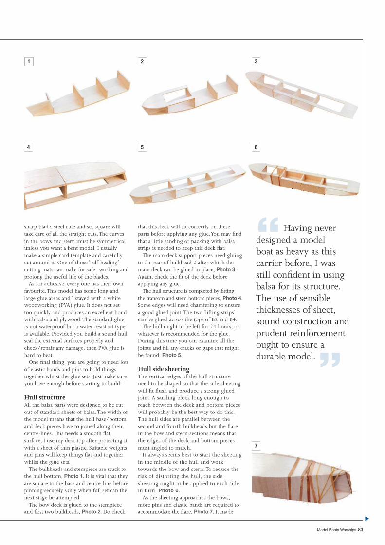
“ Having never designed a model boat as heavy as this carrier before, I was still confi dent in using balsa for its structure. The use of sensible thicknesses of sheet, sound construction and prudent reinforcement ought to ensure a durable model. ”
Model Boats Warships 83
sharp blade, steel rule and set square will take care of all the straight cuts. The curves in the bows and stern must be symmetrical unless you want a bent model. I usually make a simple card template and carefully cut around it. One of those ‘self-healing’ cutting mats can make for safer working and prolong the useful life of the blades.
As for adhesive, every one has their own favourite. This model has some long and large glue areas and I stayed with a white woodworking (PVA) glue. It does not set too quickly and produces an excellent bond with balsa and plywood. The standard glue is not waterproof but a water resistant type is available. Provided you build a sound hull, seal the external surfaces properly and check/repair any damage, then PVA glue is hard to beat.
One fi nal thing, you are going to need lots of elastic bands and pins to hold things together whilst the glue sets. Just make sure you have enough before starting to build!
Hull structureAll the balsa parts were designed to be cut out of standard sheets of balsa. The width of the model means that the hull base/bottom and deck pieces have to joined along their centre-lines. This needs a smooth fl at surface, I use my desk top after protecting it with a sheet of thin plastic. Suitable weights and pins will keep things fl at and together whilst the glue sets.
The bulkheads and stempiece are stuck to the hull bottom, Photo 1. It is vital that they are square to the base and centre-line before pinning securely. Only when full set can the next stage be attempted.
The bow deck is glued to the stempiece and fi rst two bulkheads, Photo 2. Do check
that this deck will sit correctly on these parts before applying any glue. You may fi nd that a little sanding or packing with balsa strips is needed to keep this deck fl at.
The main deck support pieces need gluing to the rear of bulkhead 2 after which the main deck can be glued in place, Photo 3. Again, check the fi t of the deck before applying any glue.
The hull structure is completed by fi tting the transom and stern bottom pieces, Photo 4. Some edges will need chamfering to ensure a good glued joint. The two ‘lifting strips’ can be glued across the tops of B2 and B4.
The hull ought to be left for 24 hours, or whatever is recommended for the glue. During this time you can examine all the joints and fi ll any cracks or gaps that might be found, Photo 5.
Hull side sheetingThe vertical edges of the hull structure need to be shaped so that the side sheeting will fi t fl ush and produce a strong glued joint. A sanding block long enough to reach between the deck and bottom pieces will probably be the best way to do this. The hull sides are parallel between the second and fourth bulkheads but the fl are in the bow and stern sections means that the edges of the deck and bottom pieces must angled to match.
It always seems best to start the sheeting in the middle of the hull and work towards the bow and stern. To reduce the risk of distorting the hull, the side sheeting ought to be applied to each side in turn, Photo 6.
As the sheeting approaches the bows, more pins and elastic bands are required to accommodate the fl are, Photo 7. It made
1 2 3
4 5 6
7
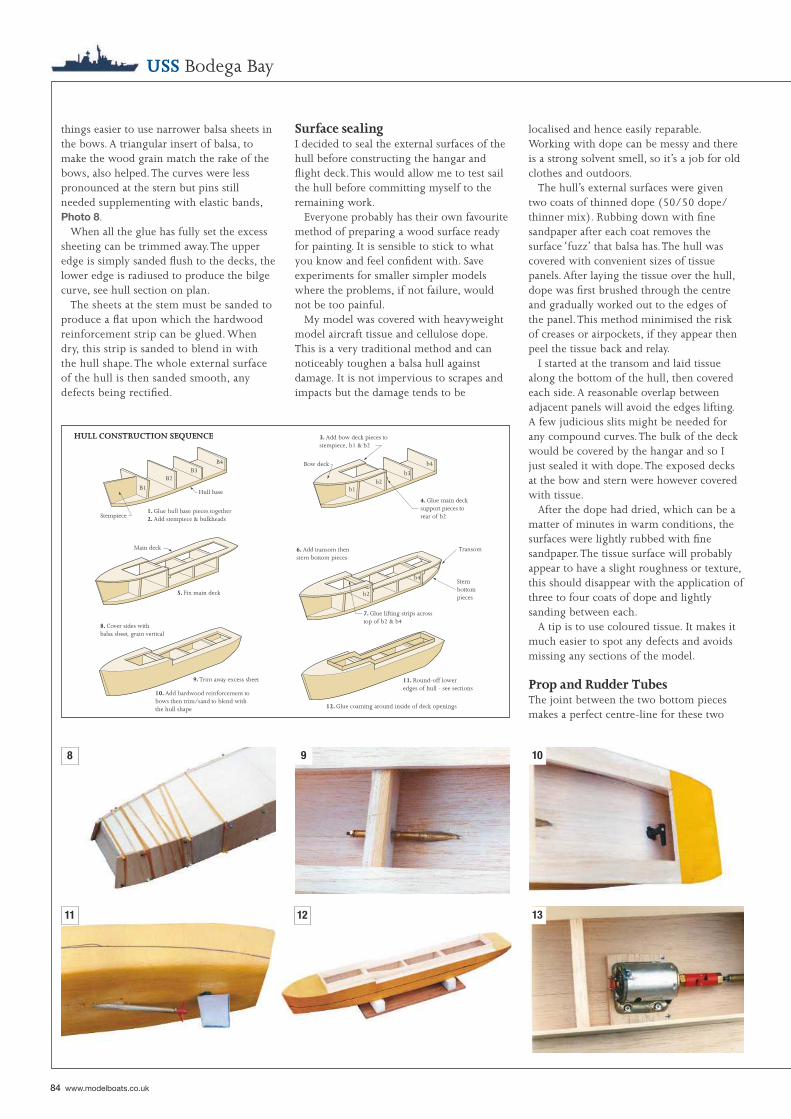
Stempiece
B1
B2B3
B4
Hull base
1. Glue hull base pieces together2. Add stempiece & bulkheads
3. Add bow deck pieces tostempiece, b1 & b2
Bow deck
b1b2
b3
b4
4. Glue main decksupport pieces torear of b2
5. Fix main deck
Main deck 6. Add transom thenstern bottom pieces
b2
b4
7. Glue lifting strips acrosstop of b2 & b4
Transom
Sternbottompieces
8. Cover sides withbalsa sheet, grain vertical
9. Trim away excess sheet
10. Add hardwood reinforcement tobows then trim/sand to blend withthe hull shape
11. Round-off loweredges of hull - see sections
12. Glue coaming around inside of deck openings
HULL CONSTRUCTION SEQUENCE
84 www.modelboats.co.uk
USS Bodega Bay
things easier to use narrower balsa sheets in the bows. A triangular insert of balsa, to make the wood grain match the rake of the bows, also helped. The curves were less pronounced at the stern but pins still needed supplementing with elastic bands, Photo 8.
When all the glue has fully set the excess sheeting can be trimmed away. The upper edge is simply sanded fl ush to the decks, the lower edge is radiused to produce the bilge curve, see hull section on plan.
The sheets at the stem must be sanded to produce a fl at upon which the hardwood reinforcement strip can be glued. When dry, this strip is sanded to blend in with the hull shape. The whole external surface of the hull is then sanded smooth, any defects being rectifi ed.
Surface sealingI decided to seal the external surfaces of the hull before constructing the hangar and fl ight deck. This would allow me to test sail the hull before committing myself to the remaining work.
Everyone probably has their own favourite method of preparing a wood surface ready for painting. It is sensible to stick to what you know and feel confi dent with. Save experiments for smaller simpler models where the problems, if not failure, would not be too painful.
My model was covered with heavyweight model aircraft tissue and cellulose dope. This is a very traditional method and can noticeably toughen a balsa hull against damage. It is not impervious to scrapes and impacts but the damage tends to be
localised and hence easily reparable. Working with dope can be messy and there is a strong solvent smell, so it’s a job for old clothes and outdoors.
The hull’s external surfaces were given two coats of thinned dope (50/50 dope/thinner mix). Rubbing down with fi ne sandpaper after each coat removes the surface ‘fuzz’ that balsa has. The hull was covered with convenient sizes of tissue panels. After laying the tissue over the hull, dope was fi rst brushed through the centre and gradually worked out to the edges of the panel. This method minimised the risk of creases or airpockets, if they appear then peel the tissue back and relay.
I started at the transom and laid tissue along the bottom of the hull, then covered each side. A reasonable overlap between adjacent panels will avoid the edges lifting. A few judicious slits might be needed for any compound curves. The bulk of the deck would be covered by the hangar and so I just sealed it with dope. The exposed decks at the bow and stern were however covered with tissue.
After the dope had dried, which can be a matter of minutes in warm conditions, the surfaces were lightly rubbed with fi ne sandpaper. The tissue surface will probably appear to have a slight roughness or texture, this should disappear with the application of three to four coats of dope and lightly sanding between each.
A tip is to use coloured tissue. It makes it much easier to spot any defects and avoids missing any sections of the model.
Prop and Rudder TubesThe joint between the two bottom pieces makes a perfect centre-line for these two
9 108
11 12 13
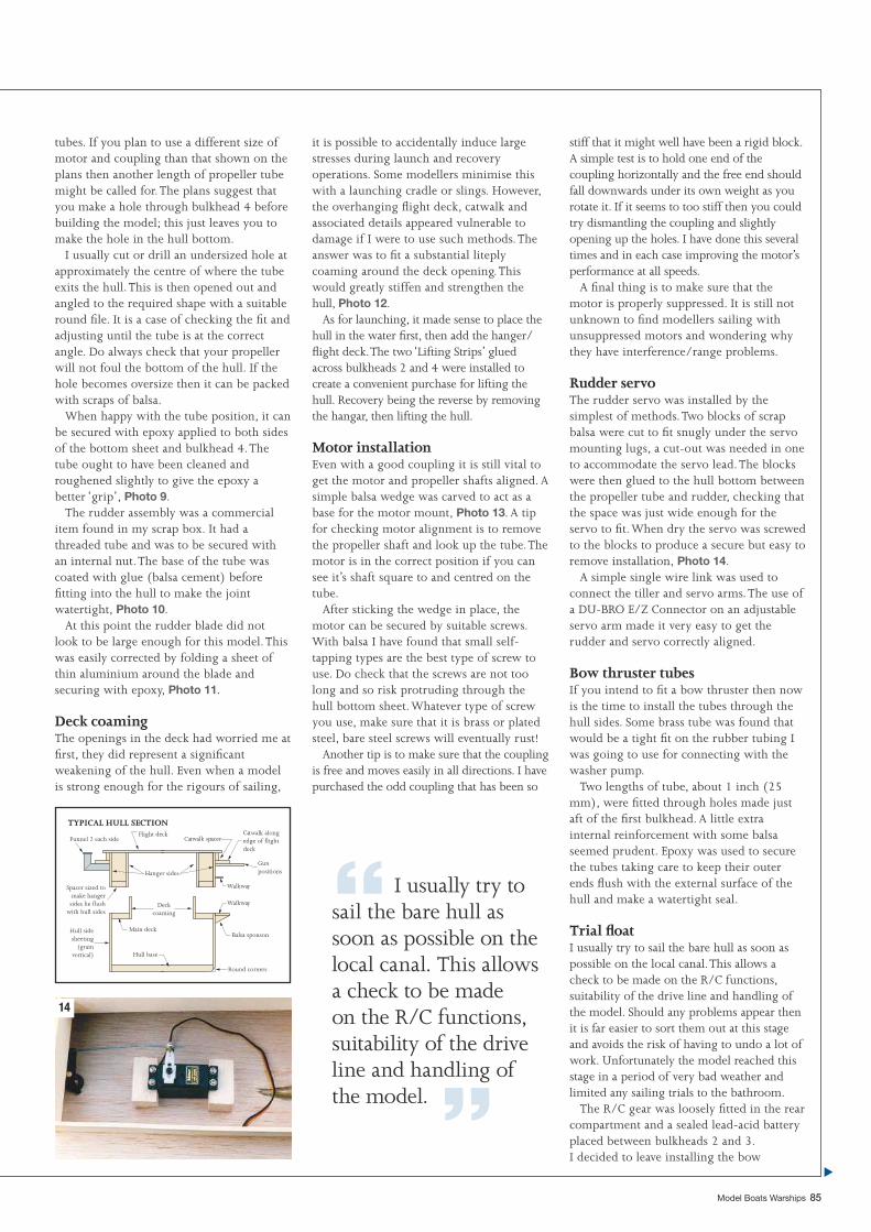
Funnel 2 each sideFlight deck
Hanger sides
Spacer sized tomake hangersides lie flush
with hull sides
Main deckHull sidesheeting
(grainvertical) Hull base
Round corners
Deckcoaming
Balsa sponson
Walkway
Walkway
Catwalk alongedge of flightdeck
Catwalk spacer
Gunpositions
TYPICAL HULL SECTION
“ I usually try to sail the bare hull as soon as possible on the local canal. This allows a check to be made on the R/C functions, suitability of the drive line and handling of the model. ”
Model Boats Warships 85
tubes. If you plan to use a different size of motor and coupling than that shown on the plans then another length of propeller tube might be called for. The plans suggest that you make a hole through bulkhead 4 before building the model; this just leaves you to make the hole in the hull bottom.
I usually cut or drill an undersized hole at approximately the centre of where the tube exits the hull. This is then opened out and angled to the required shape with a suitable round fi le. It is a case of checking the fi t and adjusting until the tube is at the correct angle. Do always check that your propeller will not foul the bottom of the hull. If the hole becomes oversize then it can be packed with scraps of balsa.
When happy with the tube position, it can be secured with epoxy applied to both sides of the bottom sheet and bulkhead 4. The tube ought to have been cleaned and roughened slightly to give the epoxy a better ‘grip’, Photo 9.
The rudder assembly was a commercial item found in my scrap box. It had a threaded tube and was to be secured with an internal nut. The base of the tube was coated with glue (balsa cement) before fi tting into the hull to make the joint watertight, Photo 10.
At this point the rudder blade did not look to be large enough for this model. This was easily corrected by folding a sheet of thin aluminium around the blade and securing with epoxy, Photo 11.
Deck coamingThe openings in the deck had worried me at fi rst, they did represent a signifi cant weakening of the hull. Even when a model is strong enough for the rigours of sailing,
it is possible to accidentally induce large stresses during launch and recovery operations. Some modellers minimise this with a launching cradle or slings. However, the overhanging fl ight deck, catwalk and associated details appeared vulnerable to damage if I were to use such methods. The answer was to fi t a substantial liteply coaming around the deck opening. This would greatly stiffen and strengthen the hull, Photo 12.
As for launching, it made sense to place the hull in the water fi rst, then add the hanger/fl ight deck. The two ‘Lifting Strips’ glued across bulkheads 2 and 4 were installed to create a convenient purchase for lifting the hull. Recovery being the reverse by removing the hangar, then lifting the hull.
Motor installationEven with a good coupling it is still vital to get the motor and propeller shafts aligned. A simple balsa wedge was carved to act as a base for the motor mount, Photo 13. A tip for checking motor alignment is to remove the propeller shaft and look up the tube. The motor is in the correct position if you can see it’s shaft square to and centred on the tube.
After sticking the wedge in place, the motor can be secured by suitable screws. With balsa I have found that small self-tapping types are the best type of screw to use. Do check that the screws are not too long and so risk protruding through the hull bottom sheet. Whatever type of screw you use, make sure that it is brass or plated steel, bare steel screws will eventually rust!
Another tip is to make sure that the coupling is free and moves easily in all directions. I have purchased the odd coupling that has been so
stiff that it might well have been a rigid block. A simple test is to hold one end of the coupling horizontally and the free end should fall downwards under its own weight as you rotate it. If it seems to too stiff then you could try dismantling the coupling and slightly opening up the holes. I have done this several times and in each case improving the motor’s performance at all speeds.
A fi nal thing is to make sure that the motor is properly suppressed. It is still not unknown to fi nd modellers sailing with unsuppressed motors and wondering why they have interference/range problems.
Rudder servoThe rudder servo was installed by the simplest of methods. Two blocks of scrap balsa were cut to fi t snugly under the servo mounting lugs, a cut-out was needed in one to accommodate the servo lead. The blocks were then glued to the hull bottom between the propeller tube and rudder, checking that the space was just wide enough for the servo to fi t. When dry the servo was screwed to the blocks to produce a secure but easy to remove installation, Photo 14.
A simple single wire link was used to connect the tiller and servo arms. The use of a DU-BRO E/Z Connector on an adjustable servo arm made it very easy to get the rudder and servo correctly aligned.
Bow thruster tubesIf you intend to fi t a bow thruster then now is the time to install the tubes through the hull sides. Some brass tube was found that would be a tight fi t on the rubber tubing I was going to use for connecting with the washer pump.
Two lengths of tube, about 1 inch (25 mm), were fi tted through holes made just aft of the fi rst bulkhead. A little extra internal reinforcement with some balsa seemed prudent. Epoxy was used to secure the tubes taking care to keep their outer ends fl ush with the external surface of the hull and make a watertight seal.
Trial fl oatI usually try to sail the bare hull as soon as possible on the local canal. This allows a check to be made on the R/C functions, suitability of the drive line and handling of the model. Should any problems appear then it is far easier to sort them out at this stage and avoids the risk of having to undo a lot of work. Unfortunately the model reached this stage in a period of very bad weather and limited any sailing trials to the bathroom.
The R/C gear was loosely fi tted in the rear compartment and a sealed lead-acid battery placed between bulkheads 2 and 3.I decided to leave installing the bow
14
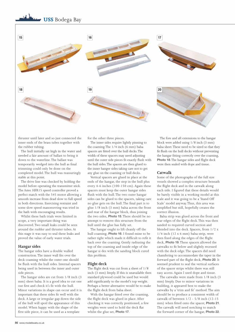
86 www.modelboats.co.uk
USS Bodega Bay
thruster until later and so just connected the inner ends of the brass tubes together with the rubber tubing.
The hull initially sat high in the water and needed a fair amount of ballast to bring it down to the waterline. The ballast was temporarily wedged into the hull as fi nal trimming could only be done on the completed model. The hull was reassuringly stable at this point.
The drive line was checked by holding the model before operating the transmitter stick. The Astec HFR15 speed controller proved a perfect match with the 545 motor allowing a smooth increase from dead slow to full speed in both directions. Exercising restraint and some slow speed manoeuvring was tried in the bath with encouraging results.
Whilst these bath trials were limited in scope, a very important thing was discovered. Two small leaks could be seen around the rudder and thruster tubes. At this stage it was easy to seal these leaks and proved the value of early water trials.
Hangar sidesThe hangar sides have a double walled construction. The inner wall fi ts over the deck coaming whilst the outer one should be fl ush with the hull sides. Internal spacers being used in between the inner and outer side pieces.
The hangar sides are cut from 1/8 inch (3 mm) sheet balsa. It is a good idea to cut one out fi rst and check it’s fi t with the hull. Minor variations in shape can occur and it is important that these sides fi t well with the deck. A large or irregular gap down the side of the hull will spoil the appearance of this model. When happy with the shape of the fi rst side piece, it can be used as a template
for the other three pieces.The inner sides require lightly pinning to
the coaming. The 1/4 inch (6 mm) balsa spacers are fi tted over the hull decks. The width of these spacers may need adjusting until the outer side pieces fi t exactly fl ush with the hull sides. The spacers are then glued to the inner hanger sides taking care not to get any glue on the coaming or hull decks.
Vertical spacers are glued in place at the ends of the hangar, the step in the hull plus every 4-6 inches (100-150 cm). Again these spacers must keep the outer hangar sides fl ush with the hull. The two outer hangar sides can be glued to the spacers, taking care no glue gets on the hull. The fi nal part is to glue 1/8 inch (3 mm) balsa across the front and rear of the hangar block, thus joining the two sides, Photo 15. There should be no attempt to remove this structure from the hull until the glue has fully set.
The hangar ought to lift cleanly off the hull coaming, Photo 16. I found mine to be rather tight which made it diffi cult to refi t it back over the coaming. Gently radiusing the top of the coaming and inside edge of the hangar si des with the sanding block cured this problem.
Flight deckThe fl ight deck was cut from a sheet of 1/8 inch (3 mm) liteply. If this is unavailable then standard plywood could be used but would add signifi cantly to the model’s top weight. Perhaps a better alternative would be to make the fl ight deck from balsa sheet.
With the hangar fi tted over the coaming, the fl ight deck was glued in place. After checking it was correctly positioned, a few weights were used to hold the deck fl at whilst the glue set, Photo 17.
The fore and aft extensions to the hangar block were added using 1/8 inch (3 mm) balsa sheet. These need to be sized so that they fi t fl ush on the hull decks without preventing the hangar fi tting correctly over the coaming, Photo 18. The hangar sides and fl ight deck were then sealed with dope and tissue.
CatwalkSome of the photographs of the full size vessels showed a complex structure beneath the fl ight deck and in the catwalk along each side. I fi gured that these details would be barely visible in a working model at this scale and it was going to be a ‘Stand Off Scale’ model anyway. Thus, this area was simplifi ed but still, hopefully creates the correct illusion.
Balsa strip was glued across the front and rear edges of the fl ight deck. This was then sanded to required curved section and blended into the deck. Spacers, from 1/2 x 1/4 inch (12 x 6 mm) balsa strip, were then fi xed along the edges of the fl ight deck, Photo 19. These spacers allowed the catwalks to fi t below and slightly recessed with the deck edge. The spacers did need chamfering to accommodate the taper in the forward part of the fl ight deck, Photo 20. It seemed prudent to seal the vertical surfaces of the spacer strips whilst there was still easy access. Again I used dope and tissue.
The catwalks were made from 1/8 inch (3 mm) liteply. Due to minor variations in building, it appeared best to make the catwalks by a ‘trim and fi t’ method. The aim should be to produce a consistent width of catwalk of between 1/2 - 5/8 inch (12-15 mm) when fi tted onto the spacer, Photo 21. The catwalk will need notching to match the forward corner of the hangar, Photo 22.
16
19
15 17
2018
Deck caoming
Main deck
Hull side
Fit innerhanger sides
against coaming
1/4"(6mm) balsasheet glued tohanger sides
1/4"(6mm) vertical spacersevery 4"-6"(100-150mm)
Glue hanger outerside to spacers
Check flush with hull sides
Add flight deck
DETAIL OF DETACHABLE HANGERFLIGHT DECK CONSTRUCTIONNote: Partial Section (LHS) Shown
TAKE CARE NOT TO GLUE TO COAMING OR DECK!
Model Boats Warships 87
Bow bulwarkThis was made by wrapping some card sheet around the bows and drawing the deck line on the card. Using this as a guide, the bulwark strip was cut from the card with the aim of producing the correct and even height above deck level and having about 1/4 inch (6 mm) to glue to the hull sides. I will confess that it took me a couple of attempts before the right shape was obtained.
After gluing to the hull the card was stiffened by gluing a narrow strip of plastic along the inside of the upper edge then applying a thin coat of dope, Photo 23. The bulwark created a small but noticeable ‘step’ where it joined the hull sides. This was removed by the used of a domestic fi ller and careful sanding. A couple more coats of thin dope sealed the card and fi ller surfaces.
Deck detailsA few details were added to the decks at this point. Card was used to make the bases of the bollards. Pins and nails, fi tted through holes drilled on these bases, formed the bollards. The hawsepipes were just tubes and washers stuck to the deck and hull sides.
The anchor winch was made up from scraps of plastic sheet and tube. I had no clear details of this item and so had to use some imagination. Luckily this winch is hidden under the forward end of the fl ight deck, Photo 24.
The aft deck area also required several bollards and these were made by the same method. A circular platform overhanging the transom stern was needed for the 5 inch gun. A disc of liteply was cut and stuck to the deck after which its upper surface was sealed with dope and tissue. A bulwark from
thin card was then added and sealed with dope, Photo 25.
WalkwaysFour walkways were needed on both sides of the model and were cut from liteply. The larger walkways on the hull sides required sponsons making from triangular sections of balsa, Photo 26. The pair on either side of the hangar were just simple rectangles.
I was worried about the vulnerability of these walkways to damage, such as might occur when attempting a docking manoeuvre. I decided to secure them to the model with epoxy and pins. This required some fi ne holes drilling through the liteply before the pins could be pushed through.
BridgeOne characteristic of escort carriers was their small bridge structure. On the model it is just a balsa box shape built up from the catwalk into the side of the fl ight deck, Photo 27. The bridge deck, from liteply, overhangs this balsa box structure.
Because the bridge now blocks the catwalk, a walkway around the bridge is needed. This was just a piece of liteply stuck to the underside of the catwalk.
Gun positionsThe plans show the shapes and locations of the many gun positions fi tted along the catwalks. Note that there are differences between each side. I cut these gun positions out of liteply and included a ‘tongue’ that could be glued to the underside of the catwalk, Photo 28. The exposed surfaces of the catwalk, gun positions and bridge were sealed with dope and tissue.
Bulwarks were needed around the gun
22
25
21 23
2624
88 www.modelboats.co.uk
guide. With the model level on its stand, I used a black waterproof marker pen secured to a suitable thickness of books and drew around the hull, Photo 34. This made painting the hull a very easy task.
When starting this model I knew that the colour of the fl ight deck was going to be a problem. These escort carriers had wooden fl ight decks which can, especially after exposure to the elements, take on many different shades. After searching through many different books, it appeared that a medium brown was the best bet. Consulting a Humbrol colour chart and No 118, US Tan, looked to be a good choice. A couple of coats, remembering to paint the lowered lift, produced an effect that was suitably dull.
On many photographs you could see the transverse tie down strips across the fl ight deck. The strips were perforated metal onto which the aircraft could be lashed, very handy in rough weather. These were drawn onto the fl ight deck with a soft pencil to give lines that were visible but only just. The success of these lines prompted me to draw the planks, catapult and forward hangar outline onto the deck.
Flight deck markings appeared to vary between ships. I settled on a simple scheme of dashed white lines, one down the centre and two along each edge. Careful application of masking tape was needed to produce parallel and even lines, Photo 35.
The catwalk decks were painted a slightly darker shade of grey than the hull colour using Humbrol No 92 Iron Grey. This trick has been used a few times to add a little more ‘depth’ to a model. The other decks and walkways were painted Deck Green, Humbrol No 88, Photo 36.
I tend to brush paint my models as, using good paint and brushes, it is not hard to achieve an acceptable fi nish. Painting can also be a relaxing and enjoyable activity, therapeutic in fact! However, looking at the carrier model revealed lots of tricky places to paint in the catwalk area. A compromise was selected, brush paint the hull below the waterline and the decks, but spray the rest.
Now for something to upset the spraying cognoscente, I was going to use cans of spray paint! I do possess a simple airbrush and fi nd it ideal for small tricky jobs that a brush could never cope with but, have never been able to justify the expense of sprayguns, compressors, etc.
My fi rst thoughts were to use cans of grey automotive primer but on searching through a local model shops stock, some spraycans of Humbrol matt Light Grey (No 64) were found. This looked like a good match with the grey used on many US Navy warships. Two 100 ml cans proved to be enough for this model.
The hull and hangar/fl ight deck were sprayed separately with the openings covered with masking tape and paper. Luckily I remembered to spray the inside of the lowered lift, Photo 33. The trick with these spray cans is to give the model numerous light coats. If you are unsure of your spraying technique, then practice on some scrap material fi rst. It is worth using an extra can to avoid a poor fi nish on your model.
The hull below the waterline was to be painted black with Humbrol No 21 gloss paint. This is not scale but it can improve a model’s appearance afl oat when you do not usually expect to see the colour of the anti-fouling paint used on the hull bottom. An accurate waterline was needed as a painting
positions and along the catwalk. I glued card strip, 3/8 inch (10 mm) wide, around each gun position, Photo 29. This card strip was cut slightly longer than needed to form a small fl ange with the catwalk. This provided a gluing point for the card strip stuck to the catwalk between the gun positions, Photo 30. The card was then sealed with dope.
The same size of card bulwark was glued around the bridge deck. After this the bridgehouse was added. Having looked long and hard at numerous photographs, this area needed some extra details and pieces of plastic strip were added to make bulwark stiffeners, pipes, vents, etc., Photo 31.
Up or down?There is a decision to take at this stage in the model’s construction, should the hangar lifts be up or down? I opted to have the aft lift partially down which, with a suitable arrangement of aircraft on the deck, could suggest that the carrier was about to fl y off a strike.
This was achieved by cutting the lift outline through the fl ight deck then fi tting a false fl oor beneath the opening, Photo 32. The internal surfaces of this opening were sealed before fi tting the deck cut-out piece to represent the lowered lift. Things looked a little bare so 1 added some plastic strip and tubes to suggest details on the inner hangar walls.
Basic paintingWith most scale models you have to strike a balance between when to stop adding details and when to start painting. There can be no hard and fast rules about this but it is usually best to paint the hull and superstructure before adding the small details which are probably easier to paint separately.
USS Bodega Bay
2827
3130
29
32
Model Boats Warships 89
available. A problem could be that the average shop is likely to have only one or two examples of the same type of kit in stock. It might be a good idea to start collecting kits as soon as you decide to build this model, by the time it is fi nished you might have the 10-12 kits needed to fi ll the fl ight deck.
Only US Navy aircraft can be realistically used on these Casablanca escort carriers. As for fi ghters both the Grumman Wildcat (F4F) and Hellcat (F6F) could be used. Another Grumman product, the Avenger (TBF), was widely used for torpedo and bombing strikes. The Douglas Dauntless (SBD) dive bomber also served on these carriers.
Sorting through my aircraft kits showed that four Hellcats and four Avengers could be built for this model. A few extra aircraft were still needed to avoid an empty appearance. A couple of Vought Corsairs were in stock but I do not think the US Navy used them on escort carriers although the Royal Navy did. Three kits of the Curtiss Helldiver (SB2C) were to hand but I was unsure if they ever operated from these small carriers. Then, totally by chance, a book on the Helldiver was found and included a picture of one landing on a Casablanca class carrier. Hence these three kits were added to the other eight.
The kits were built up as per the instructions except for a couple of changes. Fitting the models to the fl ight deck required a secure but not too permanent method. During the assembly of the fuselages a length of stiff plastic coated wire was added. This was long enough to extend below the aircraft and fi t into a hole made through the deck. When painted black this wire was hard to spot, Photo 41.
introduces the confl icting demands of a robust yet still delicate looking structure. I opted to solder up the mast and aerial from brass wire using simple jigs from scrap balsa and pins, Photo 38. This might sound tricky but by cutting the wire to just the right lengths, keeping everything clean and using a 40 watt iron, it can be easier than you think. Plastic sheet was used for the two mast platforms and the whole assembly fi tted onto a small deckhouse, Photo 39. For ease of transport, the deckhouse was secured to the bridge with small pegs.
Between the gun positions, life rafts were fi tted to the catwalk. The simple shape of an oval tube can be troublesome to make consistently. Having struggled (and usually failed!) to bend tubing in earlier projects, I now use solder. A suitable size of solder is wound around an oval former after which individual rings are cut off. These are then stuck to plastic card with Superglue. The life rafts are cut from the plastic and the excess trimmed away. Any gaps can be fi lled and, as a precaution, a bead of contact adhesive is run around the inside of the solder/plastic joint, Photo 40.
All these detail items are probably better painted before adding to the model. One of the. best ways I have found is to stick them onto some scrap wood strips with double sided tape or Blu-Tack. This will hold the item securely enough for spray or brush painting yet allows its easy removal for fi tting to the model.
AircraftA recent check in a couple of local model shops revealed that suitable 1:144 scale aircraft kits, whilst not as common as more popular scales like 1:72, ought to be
DetailingAt this point you are faced with a seemingly endless number of items to make. It is not surprising that many modellers will just fi t the basic details then start sailing their models, adding the missing items over a period of time. The only reason I did not go down this route was the weather, far too bad to think about sailing anything.
The four funnels were made from some oval section plastic pipe. Alternatives would be card tubes or carving from balsa. These exit horizontally through the hangar sides just below the catwalk, then turn upwards through 90 degrees.
The bow area was fi nished off by adding the anchors and chains, Photo 37. A suitable number was needed on both sides of the bow. As the model was not based on a specifi c vessel, hence the fi ctitious name Bodega Bay, an equally fi ctitious number was needed. The US Navy’s escort carrier numbers stopped around 130 so I could use 144, which also refl ects the model’s scale. These numbers were cut from some self-adhesive plastic fi lm. I am sure fi lm buffs will have latched on to the origin of this model’s name by now.
Numerous light guns are needed and some degree of mass production is called for. At this scale it is enough to suggest these items using wire, pins, tubing and plastic card. A useful tip is to start by making more than you need, any mistakes can be discarded along the way. The single 5 inch gun mounted on the stern is almost a relief after the smaller weapons. Again plastic card plus tubing can make a realistic item.
A short lattice mast supporting the radar aerial was a distinctive feature of these vessels. At 1:144 scale making this item
34
37
33 35
3836
AIRCRAFT FROM COMMERCIAL KITSOR SCRATCH BUILT FROM BALSA/CARD
Grumman F6F Hellcat Grumman TBF Avenger
90 www.modelboats.co.uk
USS Bodega Bay
The other change was to build the Helldivers with folded wings, thus allowing one to be fi tted on the hangar lift. This involved cutting the wings along the fold lines and gluing them at the correct angle. A simple jig was made from balsa and pins to ensure that nothing moved, Photo 42. If you decide to do this then take care to fold them the correct way. The Helldiver’s wings folded upwards whilst Grumman aircraft folded back alongside the fuselage.
When completed the aircraft were arranged on the fl ight deck with the fi ghters to fl y off fi rst, followed by the Avengers then the Helldivers. Small holes were then made
through the deck for the securing wires. A spot of contact adhesive on the underside of the deck fi xed the wire and hence the aircraft in place.
Satin sprayAt this stage the model was a mixture of matt and gloss paints. For better realism and durability, the whole model was given several light dustings with a clear satin varnish. Spray cans of PlastiKote Polyurethane varnish, from a local hardware store, have always worked well. There is only one possible problem in that a heavy coat of varnish could soften and damage the paint
41
39 40
44
42 43
fi nish. Several light coats, with drying time between, should avoid this problem.
R/C installationThe motor and rudder servo had been left in the model from the initial bath trails, so it was just a case producing a tidy internal layout. The receiver and speed controller were fi tted into the rear compartment. I used a block of foam plastic with two cut-outs to hold them secure, Photo 43.
The drive battery, a 6 volt 10 Ah sealed lead-acid type, fi tted into the compartment between bulkheads 2 and 3. Two lengths of foam plastic, placed either side of the battery, prevented it from moving whilst sailing but allowed for easy removal.
The auto windscreen washer pump was connected to the bow thruster tubes in the fi rst compartment. Again, two lengths of foam plastic were used to prevent movement. This left a convenient space for the pump switcher unit, Photo 44. 1 was using a servo mounted microswitch system which would give the pump forwards-stop-reverse control. Past experience had shown that it was perfectly adequate for this type of bow thruster.
Re-ballastingThe model was returned to the bath to carry out the permanent fi tting of the ballast. I say permanent but ballast is glued in place with either a latex adhesive or bath sealant, both hold it securely but allow for removal at any later time. This is desirable should you ever want to change things.
This time a little extra care was needed to ensure that the model fl oated on the waterline and was level. The R/C system checked out OK and stability looked good. It was just a case of waiting for decent weather to carry out the sailing trials.
Sailing trialsThe fi rst good day to sail was a bright if a little windy day. This made the club lake slightly choppy, not perfect conditions for testing a new model but I was tired of waiting.
The R/C functions, including a range check, proved OK so the model was placed in the lake. I was very glad of the two ‘lifting strips’ as they allowed me to launch
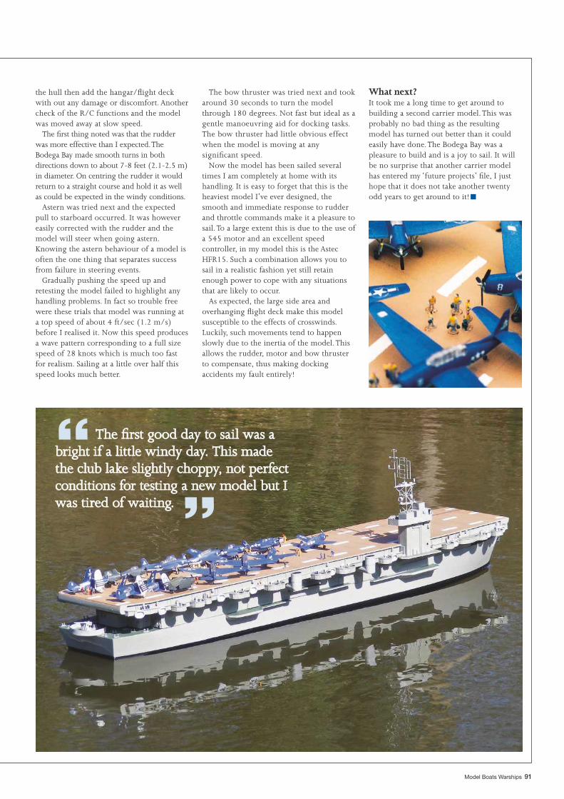
“ The fi rst good day to sail was a The fi rst good day to sail was a bright if a little windy day. This made bright if a little windy day. This made the club lake slightly choppy, not perfect the club lake slightly choppy, not perfect conditions for testing a new model but I conditions for testing a new model but I was tired of waiting. was tired of waiting. ”
■
Model Boats Warships 91
the hull then add the hangar/fl ight deck with out any damage or discomfort. Another check of the R/C functions and the model was moved away at slow speed.
The fi rst thing noted was that the rudder was more effective than I expected. The Bodega Bay made smooth turns in both directions down to about 7-8 feet (2.1-2.5 m) in diameter. On centring the rudder it would return to a straight course and hold it as well as could be expected in the windy conditions.
Astern was tried next and the expected pull to starboard occurred. It was however easily corrected with the rudder and the model will steer when going astern. Knowing the astern behaviour of a model is often the one thing that separates success from failure in steering events.
Gradually pushing the speed up and retesting the model failed to highlight any handling problems. In fact so trouble free were these trials that model was running at a top speed of about 4 ft/sec (1.2 m/s) before I realised it. Now this speed produces a wave pattern corresponding to a full size speed of 28 knots which is much too fast for realism. Sailing at a little over half this speed looks much better.
The bow thruster was tried next and took around 30 seconds to turn the model through 180 degrees. Not fast but ideal as a gentle manoeuvring aid for docking tasks. The bow thruster had little obvious effect when the model is moving at any signifi cant speed.
Now the model has been sailed several times I am completely at home with its handling. It is easy to forget that this is the heaviest model I’ve ever designed, the smooth and immediate response to rudder and throttle commands make it a pleasure to sail. To a large extent this is due to the use of a 545 motor and an excellent speed controller, in my model this is the Astec HFR15. Such a combination allows you to sail in a realistic fashion yet still retain enough power to cope with any situations that are likely to occur.
As expected, the large side area and overhanging fl ight deck make this model susceptible to the effects of crosswinds. Luckily, such movements tend to happen slowly due to the inertia of the model. This allows the rudder, motor and bow thruster to compensate, thus making docking accidents my fault entirely!
What next?It took me a long time to get around to building a second carrier model. This was probably no bad thing as the resulting model has turned out better than it could easily have done. The Bodega Bay was a pleasure to build and is a joy to sail. It will be no surprise that another carrier model has entered my ‘future projects’ fi le, I just hope that it does not take another twenty odd years to get around to it!
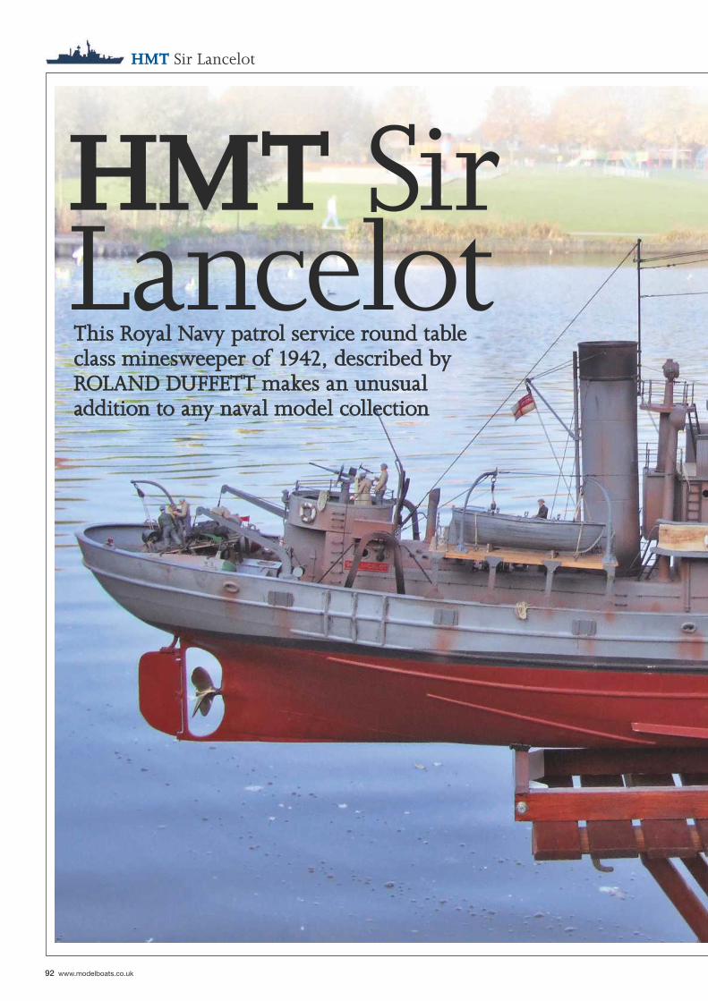
92 www.modelboats.co.uk
HMT Sir Lancelot
HMT Sir LancelotThis Royal Navy patrol service round table This Royal Navy patrol service round table class minesweeper of 1942, described by class minesweeper of 1942, described by ROLAND DUFFETT makes an unusual ROLAND DUFFETT makes an unusual addition to any naval model collectionaddition to any naval model collection
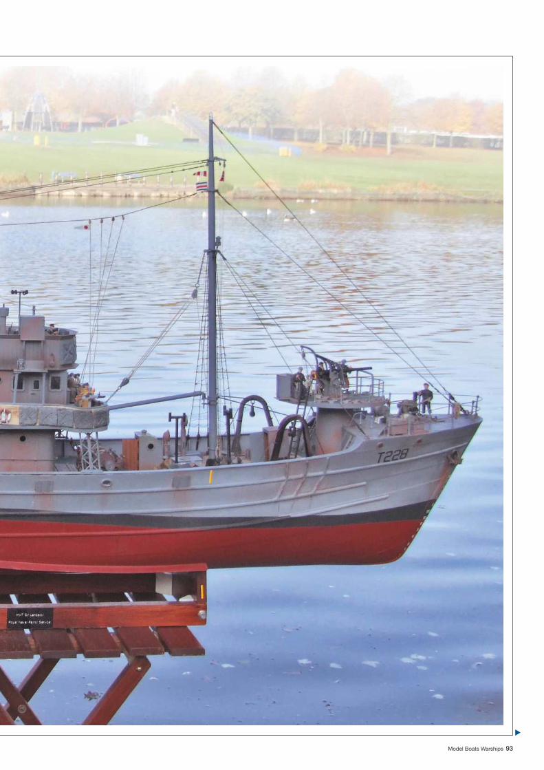
Model Boats Warships 93
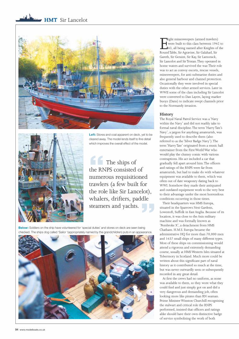
“ The ships of the RNPS consisted of numerous requisitioned trawlers (a few built for the role like Sir Lancelot), whalers, drifters, paddle steamers and yachts. ”
94 www.modelboats.co.uk
HMT Sir Lancelot
Eight minesweepers (armed trawlers) were built to this class between 1942 to 43, all being named after Knights of the
Round Table, Sir Agravine, Sir Galahad, Sir Gareth, Sir Geraint, Sir Kay, Sir Lamorack,Sir Lancelot and Sir Tristan. They operated in home waters and survived the war. Their role was to act as convoy escorts, rescue vessels, minesweepers, for anti-submarine duties and also general harbour and channel protection. Occasionally they were involved in special duties with the other armed services. Later in WWII some of the class including Sir Lancelot were converted to Dan Layers, laying marker buoys (Dans) to indicate swept channels prior to the Normandy invasion.
HistoryThe Royal Naval Patrol Service was a ‘Navy within the Navy’ and did not readily take to formal naval discipline. The term ‘Harry Tate’s Navy’, a jargon for anything amateurish, was frequently used to describe them (also referred to as the ‘Silver Badge Navy’). The term ‘Harry Tate’ originated from a music hall entertainer from the First World War who would play the clumsy comic with various contraptions. His act included a car that gradually fell apart around him. The offi cers and ratings of the RNPS were far from amateurish, but had to make do with whatever equipment was available to them, which was often out of date weaponry dating back to WWI. Somehow they made their antiquated and outdated equipment work to the very best to their advantage under the most horrendous conditions occurring in those times.
Their headquarters was HMS Europa, situated in the Sparrows Nest Gardens, Lowestoft, Suffolk in East Anglia. Because of its location, it was close to the Axis military machine and was formally known as ‘Pembroke X’, a detachment from HMS Chatham. H.M.S. Europa became the administrative HQ for more than 70,000 men and 1637 small ships of many different types. Most of these ships on commissioning would attend a rigorous and extremely demanding course, usually at HMS Western Isles situated at Tobermory in Scotland. Much more could be written about this signifi cant part of naval history as it contributed so much at the time, but was never outwardly seen or subsequently recorded in any great detail.
At fi rst the crews had no uniform, as none was available to them, so they wore what they could fi nd and just simply got on and did a very dangerous and demanding job, often looking more like pirates than RN seaman. Prime Minister Winston Churchill recognising the stalwart and critical role the RNPS performed, insisted that offi cers and ratings alike should have their own distinctive badge of service symbolising the work of both
Left: Stores and coal apparent on deck, yet to be cleared away. The model lends itself to fi ne detail which improves the overall effect of the model.
Below: Soldiers on the ship have volunteered for ‘special duties’ and stores on deck are seen being checked. The ships dog called ‘Sailor ‘(appropriately named by the grandchildren) puts in an appearance.
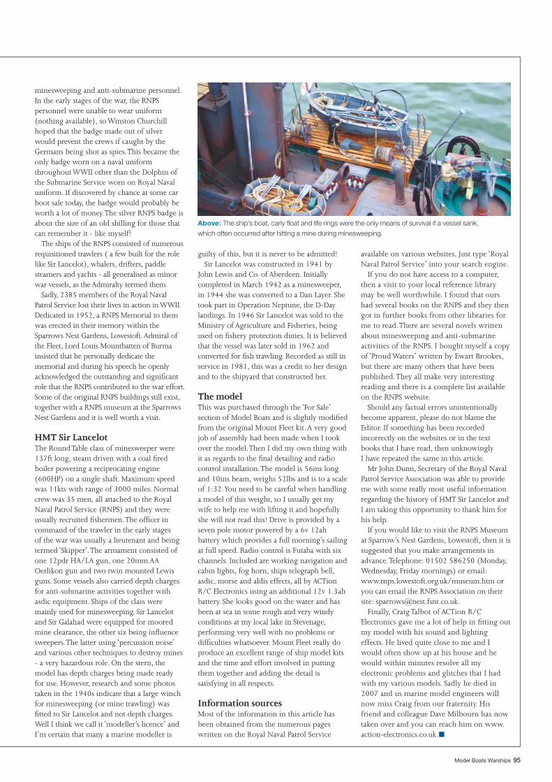
Model Boats Warships 95
guilty of this, but it is never to be admitted!Sir Lancelot was constructed in 1941 by
John Lewis and Co. of Aberdeen. Initially completed in March 1942 as a minesweeper, in 1944 she was converted to a Dan Layer. She took part in Operation Neptune, the D-Day landings. In 1946 Sir Lancelot was sold to the Ministry of Agriculture and Fisheries, being used on fi shery protection duties. It is believed that the vessel was later sold in 1962 and converted for fi sh trawling. Recorded as still in service in 1981, this was a credit to her design and to the shipyard that constructed her.
The modelThis was purchased through the ‘For Sale’ section of Model Boats and is slightly modifi ed from the original Mount Fleet kit. A very good job of assembly had been made when I took over the model. Then I did my own thing with it as regards to the fi nal detailing and radio control installation. The model is 56ins long and 10ins beam, weighs 52lbs and is to a scale of 1:32. You need to be careful when handling a model of this weight, so I usually get my wife to help me with lifting it and hopefully she will not read this! Drive is provided by a seven pole motor powered by a 6v 12ah battery which provides a full morning’s sailing at full speed. Radio control is Futaba with six channels. Included are working navigation and cabin lights, fog horn, ships telegraph bell, asdic, morse and aldis effects, all by ACTion R/C Electronics using an additional 12v 1.3ah battery. She looks good on the water and has been at sea in some rough and very windy conditions at my local lake in Stevenage, performing very well with no problems or diffi culties whatsoever. Mount Fleet really do produce an excellent range of ship model kits and the time and effort involved in putting them together and adding the detail is satisfying in all respects.
Information sourcesMost of the information in this article has been obtained from the numerous pages written on the Royal Naval Patrol Service
minesweeping and anti-submarine personnel. In the early stages of the war, the RNPS personnel were unable to wear uniform (nothing available), so Winston Churchill hoped that the badge made out of silver would prevent the crews if caught by the Germans being shot as spies. This became the only badge worn on a naval uniform throughout WWII other than the Dolphin of the Submarine Service worn on Royal Naval uniform. If discovered by chance at some car boot sale today, the badge would probably be worth a lot of money. The silver RNPS badge is about the size of an old shilling for those that can remember it - like myself!
The ships of the RNPS consisted of numerous requisitioned trawlers ( a few built for the role like Sir Lancelot), whalers, drifters, paddle steamers and yachts - all generalised as minor war vessels, as the Admiralty termed them.
Sadly, 2385 members of the Royal Naval Patrol Service lost their lives in action in WWII. Dedicated in 1952, a RNPS Memorial to them was erected in their memory within the Sparrows Nest Gardens, Lowestoft. Admiral of the Fleet, Lord Louis Mountbatten of Burma insisted that he personally dedicate the memorial and during his speech he openly acknowledged the outstanding and signifi cant role that the RNPS contributed to the war effort. Some of the original RNPS buildings still exist, together with a RNPS museum at the Sparrows Nest Gardens and it is well worth a visit.
HMT Sir LancelotThe Round Table class of minesweeper were 137ft long, steam driven with a coal fi red boiler powering a reciprocating engine (600HP) on a single shaft. Maximum speed was 11kts with range of 3000 miles. Normal crew was 35 men, all attached to the Royal Naval Patrol Service (RNPS) and they were usually recruited fi shermen. The offi cer in command of the trawler in the early stagesof the war was usually a lieutenant and being termed ‘Skipper’. The armament consisted of one 12pdr HA/LA gun, one 20mm AA Oerlikon gun and two twin mounted Lewis guns. Some vessels also carried depth charges for anti-submarine activities together with asdic equipment. Ships of the class were mainly used for minesweeping. Sir Lancelot and Sir Galahad were equipped for moored mine clearance, the other six being infl uence sweepers. The latter using ‘percussion noise’ and various other techniques to destroy mines - a very hazardous role. On the stern, the model has depth charges being made ready for use. However, research and some photos taken in the 1940s indicate that a large winch for minesweeping (or mine trawling) was fi tted to Sir Lancelot and not depth charges. Well I think we call it ‘modeller’s licence’ and I’m certain that many a marine modeller is
available on various websites. Just type ‘Royal Naval Patrol Service’ into your search engine.
If you do not have access to a computer, then a visit to your local reference library may be well worthwhile. I found that ours had several books on the RNPS and they then got in further books from other libraries for me to read. There are several novels written about minesweeping and anti-submarine activities of the RNPS. I bought myself a copy of ‘Proud Waters’ written by Ewart Brookes, but there are many others that have been published. They all make very interesting reading and there is a complete list available on the RNPS website.
Should any factual errors unintentionally become apparent, please do not blame the Editor. If something has been recorded incorrectly on the websites or in the text books that I have read, then unknowinglyI have repeated the same in this article.
Mr John Dunn, Secretary of the Royal Naval Patrol Service Association was able to provide me with some really most useful information regarding the history of HMT Sir Lancelot and I am taking this opportunity to thank him for his help.
If you would like to visit the RNPS Museum at Sparrow’s Nest Gardens, Lowestoft, then it is suggested that you make arrangements in advance. Telephone: 01502 586250 (Monday, Wednesday, Friday mornings) or email:www.rnps.lowestoft.org.uk/museum.htm or you can email the RNPS Association on their site: [email protected].
Finally, Craig Talbot of ACTion R/C Electronics gave me a lot of help in fi tting out my model with his sound and lighting effects. He lived quite close to me and I would often show up at his house and he would within minutes resolve all my electronic problems and glitches that I had with my various models. Sadly he died in 2007 and us marine model engineers will now miss Craig from our fraternity. His friend and colleague Dave Milbourn has now taken over and you can reach him on www.action-electronics.co.uk.
Above: The ship’s boat, carly fl oat and life rings were the only means of survival if a vessel sank, which often occurred after hitting a mine during minesweeping.
■
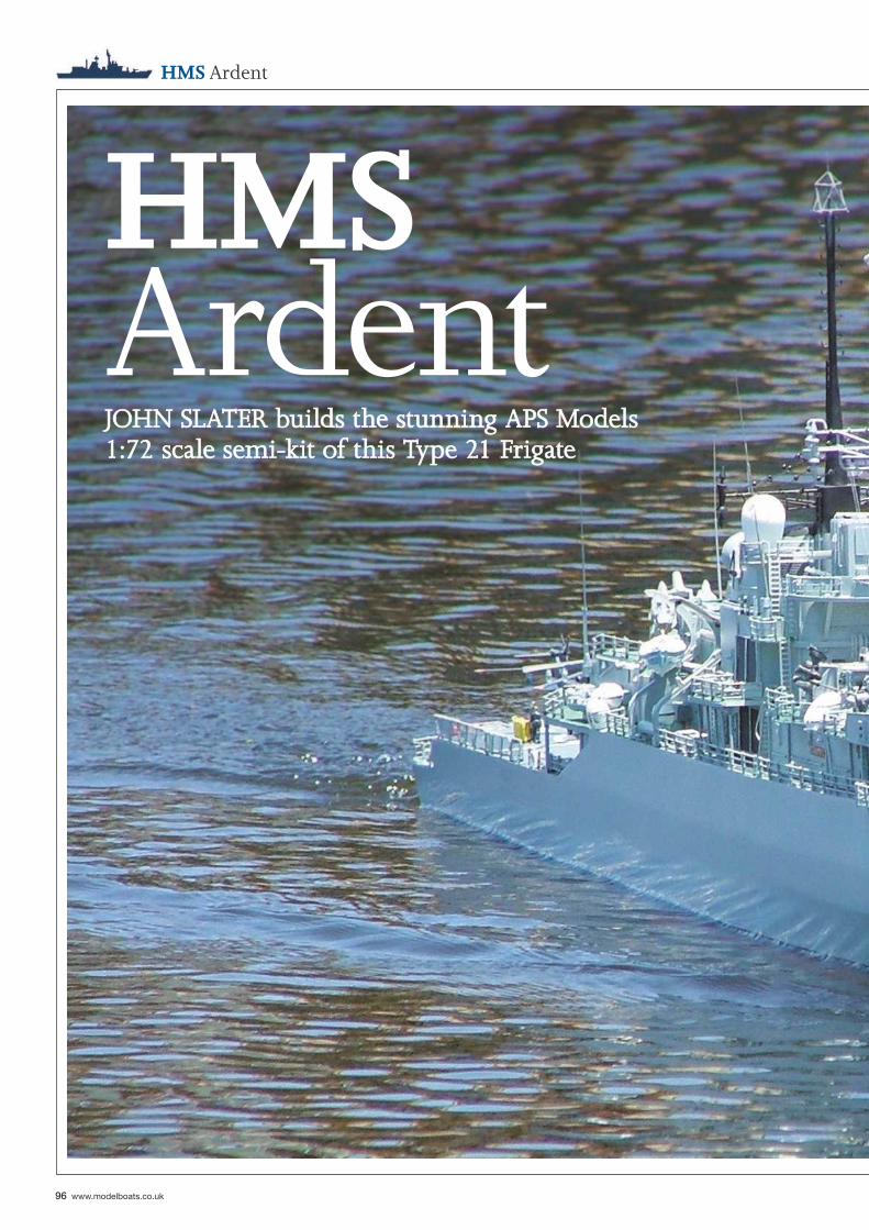
96 www.modelboats.co.uk
HMS Ardent
HMSArdentJOHN SLATER builds the stunning APS Models JOHN SLATER builds the stunning APS Models 1:72 scale semi-kit of this Type 21 Frigate1:72 scale semi-kit of this Type 21 Frigate
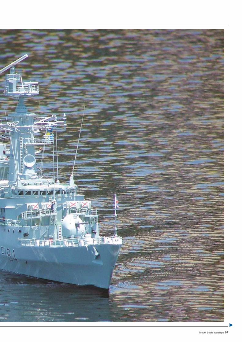
Model Boats Warships 97
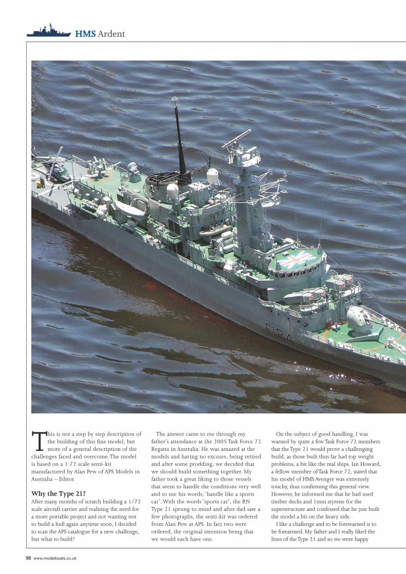
98 www.modelboats.co.uk
HMS Ardent
This is not a step by step description of the building of this fi ne model, but more of a general description of the
challenges faced and overcome. The model is based on a 1:72 scale semi-kit manufactured by Alan Pew of APS Models in Australia – Editor.
Why the Type 21?After many months of scratch building a 1/72 scale aircraft carrier and realising the need for a more portable project and not wanting not to build a hull again anytime soon, I decided to scan the APS catalogue for a new challenge, but what to build?
On the subject of good handling, I was warned by quite a few Task Force 72 members that the Type 21 would prove a challenging build, as those built thus far had top weight problems, a bit like the real ships. Ian Howard, a fellow member of Task Force 72, stated that his model of HMS Avenger was extremely touchy, thus confi rming this general view. However, he informed me that he had used timber decks and 1mm styrene for the superstructure and confessed that he just built the model a bit on the heavy side.
I like a challenge and to be forewarned is to be forearmed. My father and I really liked the lines of the Type 21 and so we were happy
The answer came to me through my father’s attendance at the 2005 Task Force 72 Regatta in Australia. He was amazed at the models and having no excuses, being retired and after some prodding, we decided that we should build something together. My father took a great liking to those vessels that seem to handle the conditions very well and to use his words; ‘handle like a sports car’. With the words ‘sports car’, the RN Type 21 sprung to mind and after dad saw a few photographs, the semi-kit was ordered from Alan Pew at APS. In fact two were ordered, the original intention being that we would each have one.
“We liked the concept of a vessel equipped with a Lynx helicopter, Exocet missiles and to a fair degree the colour contrast of green decks and the colourful Cheverton launch ”
Model Boats Warships 99
nonetheless with our decision. Our decision was reinforced when researching the class, which involved the purchase of the excellent book: Modern Combat Ships 5, Type 21 by Captain John Lippiett RN. I have high praise for Navy Books (www.navybooks.com), the Royal Mail and Australia Postal Service that had the book delivered to me in Australia by ordinary air mail just three days after it was ordered and this was four days before Christmas!
John Lippiett’s book is extremely informative of these ships, and I believe to be a most defi nitive source of information which it certainly was for us. That said, there are some areas of interest to the modeller that are
lacking, such as specifi c paint colours applied in different areas and the timescale when the ships received particular upgrades, if any. The bottom line though is that it is an excellent book, written from a balanced positive personal perspective that clearly identifi es some of their defi ciencies as well.
In contrast, I soon found on the internet a plethora of scathing criticism of the ships, naming stability problems, aluminium superstructures that burnt very well, lack of room and topweight too excessive for mid-life upgrades. Much of this criticism failed to factor in the views of those who crewed these ships risking their lives and who came back time and again to serve on them. Their popularity amongst the crews for their generous living quarters, general working conditions and their effectiveness, seemed absent. So too was the fact that HM Ships Antelope and Ardent absorbed a tremendous amount of damage in the Falklands War of 1982 prior to their loss. Yes, the aluminium superstructures caught fi re, but what might have happened if a contemporary ship were attacked in the same way?
The book assisted with actual ship choice for the model, as we liked the concept of a
vessel equipped with a Lynx helicopter, Exocet missiles and to a fair degree the colour contrast of green decks and the colourful Cheverton launch. With those colours alone, we were looking at a late 1970’s to just pre-Falklands era ship. The book revealed that HMS Ardent had Exocet missiles and a Lynx before the Falklands War. HMS Amazon had a Lynx for trials earlier and indeed HMS Arrow was actually the fi rst to be assigned a Lynx.
So we decided on HMS Ardent and furthermore as Task Force 72 operational Type 21’s thus far consisted of HM Ships Active and Avenger, we would now be adding to this Type 21 fl otilla. I should point out again that we initially intended to build two Type 21’s, the second being HMS Arrow and both scheduled for basic construction by me with this second model then being detailed, fi tted out and fi nished by my father. He (my father) unfortunately then fell head over heels for model yacht racing, so HMS Arrow was paid off prior to her completion to another Task Force 72 member. This article therefore focuses on my HMS Ardent.
Ian Howard very kindly gave me his plans for HMS Avenger, a similar ship of the class.
100 www.modelboats.co.uk
HMS Ardent
What I needed to build were:The funnel, superstructure, deck and masts plus other small detail parts as well as installing the shafts and motors etc.
Now, the current semi-kit includes a few extra detail parts to that which I received. A most useful addition is that you now receive the funnel, which is of lightweight GRP, the master of which I made and it includes the mast base just ahead of it. In addition I made moulds for various ventilator exit grills and Type 992 radar director tracker bases. All of these are now standard features of the semi-kit.
Starting constructionThe very fi rst job upon receiving the package is to check that all the parts are included, then to give the hull a good wash down with some warm soapy water and give the outer hull a light rub down with fi ne wet and dry sandpaper. The next task, save for building a secure boat stand, is to affi x lightweight timber strips along the entire length of the hull edges, suitably positioned to support the decks. These stringers help maintain the hull’s shape. These longitudinal deck edge stringers allow cross sectional beams to be inserted into the hull, maintaining the correct profi le. If you fi x cross section beams to the hull without reinforcing the deck edge, the sides will tend to bulge around those beams.
The lightweight stringers and cross sectional supports were glued in place using 24hr epoxy. A word of caution here, is that some fi ve minute or fast setting epoxy glues are actually not fully waterproof when cured.
One perplexing issue that we had to resolve was what masts and mast equipment were on HMS Ardent circa late 1970’s. The mainmast, just in front of the funnel had gone through some noticeable changes and the foremast just behind the bridge had electronic countermeasure sensors (ECM) additions that were quite noticeable features. I am very grateful to Michael Brown of Task Force 72 for supplying me with a good number of date assigned photographs for all the ships of this class, which with the many photographs in the book made recognition of relevant features for the year of build of my model much more accurate. Michael also provided some great on board shots of HMS Amazon and of a model of HMS Active that he photographed on one of his frequent UK visits to Portsmouth Historic Dockyard. Michael is our local RN painting expert and was also very quick in giving me exact colour formulas for the decks and hull.
The APS semi-kitAllan Pew of APS Models does great work in all the various 1/72 scale kits and semi-kits he supplies. What you get is all of very high quality and at a reasonable price. The kit came with:• GRP hull• 4 x Exocet missile canisters• 4.5in Mk 8 gun• 4 x 20mm Oerlikon machine guns and mountings• 2 x Triple STWS torpedo tubes • 1 Seacat mount• 2 x ECM aerials• 2 x Chaff launchers• 2 x Sonar decoys• 2 x SM6 Sea Rider infl atable boats• 2 x 912 Radar directors (tracker radar)• 1 Abbey Hill radar• 4 x Witches Hat antennae• 25 x watertight doors• 2 x electric winches• 30 x bulkhead light fi ttings• 10 x liferaft canisters• 1 x Cheverton launch• 1 x 27ft Motor Whaler hull• 10 x bollards• 12 x fairleads• 2 x signal lamps• 10 x fi re hose racks• 1 x stern hoist• 3 x anchor windlasses• 2 x anchors• Also included were stainless steel propshafts, A-frames, stuffi ng boxes and rudders.• What I needed to buy were:• Propellers (optional extra from APS)• Motors• Speed controllers, batteries and r/c• Building materials, styrene and wood, brass rod etc.• Consumables
Sonar domeThe next stage in the construction was to fi t this to the hull. To heed the warnings of those who have built the kit previously, we sought to keep weight as low as possible. In this respect my father, a keen r/c yachtsman hit upon a great idea. He suggested we make the dome out of solid lead. To do so would provide a lead like keel in a position very low down, actually lower than the bottom of the hull and the ballast could then be disguised as the sonar dome. My father built a ceramic mould and cast the dome. Two stainless steel bolts inserted into the lead secured the dome to the hull.
The relatively rough outer skin of the lead sonar dome was then fi lled with fi breglass fi ller and sanded to shape. This outer skin was then also coated with a layer of gel coat with a special drying agent added (gel coat remains tacky unless air is excluded or a special additive is included the catalysed mixture). Inside the hull a stainless steel plate was inserted over and around the bolts to spread the load and a layer of chopped strand mat and fi breglass resin secured everything permanently.
Top view of hull section with longitudinal stringers and cross beams
Top view of hull section with no longitudinal stringers
Hull sides Longitudinal stringers
Cross beams
Without stringer bracing along the hull sides - deviations(exaggerated in the illustration below) can occur along thehull at points where cross beams are installed
Pressure points that cause distortions (exaggerated in diagram)
Hull sides
Cross beams
Sonar dome (lead) installationStainless steel nuts and plate covered in car bog and overlaid withfibregalss and gelcoat
Stainless steel bolts inside lead sonar dome
Stainless steel plate inside hullStainless steel nuts
Inside hull
Bow
Sonar dome - solid lead
Model Boats Warships 101
at Task Force 72 kindly evaluated some motor and propeller combinations and the Mabuchi 555 on 12 volts was the motor that showed the most promise. With the radio gear loosely installed in the model, I ventured out for a test run on Manly Dam which is my local freshwater waterway. The results were very good, producing a great turn of speed and positive response from the motors.
Taking the model back to the test tank we tethered the model against the sides of the tank and ran her at full speed for 30 minutes. Five amps was drawn for both motors combined (i.e. just 2.5 amps each). However, the motors were extremely hot to touch at the end of the test.
What was required was a cooling source, so I fi tted to each motor, two r/c car motor heat sinks and a cooling fan in front of them. In addition, I fi tted a single 12v 90mm computer cooling fan over them. Repeating the test again, with the motors running fl at out for 30 minutes, resulted in a maximum of 2.3 amps drawn by each motor, but more important that were only mildly warm as against being painfully hot to the touch previously.
Running gear and tank testingAttention could now be given to installing the running gear and rudders. APS supplied an excellent set of brass propellers, ‘A’ frames, stainless steel shafts, stuffi ng tubes, connecting collars and universal joints for the drive train as well as the rudders. Once these were all installed, preliminary fl otation tests were carried out. The model seemed to sit slightly above the waterline, temporarily indicated with a marker pen and electrical tape. Two 10Ah 6v SLA batteries were laid fl at and low along the bottom of the hull as I planned to run the model off a 12v system by wiring the batteries in series with independent motor speed controls. The initial fl oatation tests were good, with the model being very stable and quick to right herself when healed her over deliberately at an extreme angle. I marked up where the batteries lay in the hull and fi xed in place a set of battery holders that I made from aluminium right angled rod.
With all the running gear and batteries in place I turned now to the motors. The Type 21 was no slouch on speed and I was determined to get this right for this model. Michael Brown
Above: The motors with additional heat sinks and the fan in front to keep the motors cool. The substantial deck edge stringers and deck beams are also visible.
Far left: The forward section of the superstructure under construction.
Left: The bracing inside the after part of the superstructure is clearly visible. This enables thin styrene to be used for the outer skin.
Below left: The main switch panel is located under where the RIB will be mounted between the two main parts of the superstructure
Below: The HMS Ardent fl oats!
102 www.modelboats.co.uk
HMS Ardent
the wind speed rises above 15 knots.A somewhat problematic decision very early
on in the construction, was that I would build the entire main deck out of styrene. On all the other models I have built, except my scratchbuilt 1:72 scale Italian aircraft carrier Giuseppe Garibaldi, the main decks have been of lightweight plywood, laminated with a thin coating of fi breglass resin. The choice with HMS Ardent to go the styrene route was primarily to save weight, but also as I needed a proper cement weld between the numerous styrene deck treads that were to be glued to it. The use of styrene for the main decks joined to a GRP hull is not without problems, as it has a much higher rate of expansion and contraction than the hull when experiencing extreme temperature variations. In a model with an ABS hull this is less of a problem, as the hull has a similar rate of expansion and contraction to styrene. This too is the case for styrene decks and superstructure, the whole structure having exactly the same rate of expansion and contraction. So, provided a superstructure just sits and is not glued down onto a deck of another material, there is no problem.
When a main deck of styrene is glued onto a GRP hull, the difference in the behaviour of these materials is quite noticeable. The differing rate of expansion of the styrene to GRP can compromise the glued joint between the two materials and can result in the deck warping or cracking of the joint. There really is no perfect method of getting around the physical limitation of joining such unlike materials and then exposing them to such hot conditions as the Australian summer sun. This may not be an issue for people in cooler climates, but it is a very real factor for us model boaters here in Australia. What I did on the Type 21 to minimise the chance of warping or cracking of the decks, was to employ signifi cant styrene underbracing both in longitudinal and cross sectional positions below the decks. These decks were then glued into position using 24 hour epoxy resin ensuring the decks were fi rmly fi xed to the hull’s longitudinal and cross-sectional timbers and braces.
Running the ship painted (which attracts more heat than unpainted white styrene which refl ects heat) in the Australian sun, has resulted thus far in no visual warping. I do expect over time to have the odd crack appear at the deck edge joint between the GRP hull and the fi xed deck areas. However, I must stress that in hindsight I will not be doing this again and will on my future projects use lightweight ply laminated with fi breglass resin for the main decks on a GRP hull. I think the reason why I have got away with using styrene main decks on this project was that in addition to the under deck bracing, the actual surface area under direct sunlight is not that large.
The construction of the foremast was similar to that of the entire superstructure. That is to say it is also a styrene space frame with a thin 0.5mm thick styrene outer skin. Great care must be taken when drilling this outer skin so as to allow the various pieces of brass rod, LEDs, tiny light globes and fi ttings to be positioned. This thin skin can easily puncture if too much pressure is applied, so great care needed to be taken with this rather delicate and intricate work.
The superstructure was built in two sections so that when completely removed it allowed almost complete access to the entire inner hull. Even the fl oor of the hangar was designed to be removable, which on hot days allows an even greater airfl ow over the cooling fans for maximum ventilation. This is probably a strange concept to readers in the UK, but in Australia it is not uncommon to have a sailing day when the air temperature is well above 30 degrees C, which is hot!
The entire superstructure sits on the deck located by coamings made from styrene strip. These strips, a minimum of 6mm high, run around the entire hull opening section and locate the superstructure positively. They also provide a barrier against water ingress, should the ship take ‘greenies’ on my local lake when
Superstructure and decksThe key to keeping the weight down and improving stability, apart from ensuring all machinery and batteries were kept as low as possible, was that the upper parts had to be as light as possible. However, I still wanted to build maximum strength into the superstructure and include all the scale detail. I also needed the best possible access into the hull for the batteries and any maintenance required. The entire superstructure, save for a few detail parts, is constructed from styrene card. Most parts of the superstructure are just 0.5mm thick and so I employed a space frame type of construction method to include maximum strength and by so doing this allowed me to keeping the bulk of the weight, which is the outer skin of the superstructure, very thin. The space frame concept is simply a series of supporting styrene beams that are fi xed in both a longitudinal and cross sectional fashion so as to support the whole structure and its outer skin. The result is a dramatic saving in top weight compared to using heavier and thicker styrene and at the same time the structure, thanks to the space frame, is also very strong. The fl ight deck area was fi tted with micro-LED’s during its construction.
Above: Full power trials in the test tank. The blocks of expanded foam hold the model fi rmly, without damaging it.
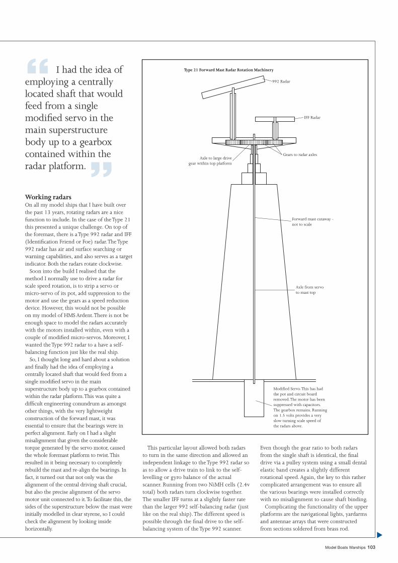
Gears to radar axles
IFF Radar
992 Radar
Forward mast cutaway -not to scale
Axle from servoto mast top
Modified Servo. This has hadthe pot and circuit boardremoved. The motor has beensuppressed with capacitors.The gearbox remains. Runningon 1.5 volts provides a veryslow turning scale speed ofthe radars above.
Axle to large drivegear within top platform
Type 21 Forward Mast Radar Rotation Machinery“ I had the idea of employing a centrally located shaft that would feed from a single modifi ed servo in the main superstructure body up to a gearbox contained within the radar platform. ”
Model Boats Warships 103
Working radarsOn all my model ships that I have built over the past 13 years, rotating radars are a nice function to include. In the case of the Type 21 this presented a unique challenge. On top of the foremast, there is a Type 992 radar and IFF (Identifi cation Friend or Foe) radar. The Type 992 radar has air and surface searching or warning capabilities, and also serves as a target indicator. Both the radars rotate clockwise.
Soon into the build I realised that the method I normally use to drive a radar for scale speed rotation, is to strip a servo or micro-servo of its pot, add suppression to the motor and use the gears as a speed reduction device. However, this would not be possible on my model of HMS Ardent. There is not be enough space to model the radars accurately with the motors installed within, even with a couple of modifi ed micro-servos. Moreover, I wanted the Type 992 radar to a have a self-balancing function just like the real ship.
So, I thought long and hard about a solution and fi nally had the idea of employing a centrally located shaft that would feed from a single modifi ed servo in the main superstructure body up to a gearbox contained within the radar platform. This was quite a diffi cult engineering conundrum as amongst other things, with the very lightweight construction of the forward mast, it was essential to ensure that the bearings were in perfect alignment. Early on I had a slight misalignment that given the considerable torque generated by the servo motor, caused the whole foremast platform to twist. This resulted in it being necessary to completely rebuild the mast and re-align the bearings. In fact, it turned out that not only was the alignment of the central driving shaft crucial, but also the precise alignment of the servo motor unit connected to it. To facilitate this, the sides of the superstructure below the mast were initially modelled in clear styrene, so I could check the alignment by looking inside horizontally.
This particular layout allowed both radars to turn in the same direction and allowed an independent linkage to the Type 992 radar so as to allow a drive train to link to the self-levelling or gyro balance of the actual scanner. Running from two NiMH cells (2.4v total) both radars turn clockwise together. The smaller IFF turns at a slightly faster rate than the larger 992 self-balancing radar (just like on the real ship). The different speed is possible through the fi nal drive to the self-balancing system of the Type 992 scanner.
Even though the gear ratio to both radars from the single shaft is identical, the fi nal drive via a pulley system using a small dental elastic band creates a slightly different rotational speed. Again, the key to this rather complicated arrangement was to ensure all the various bearings were installed correctly with no misalignment to cause shaft binding.
Complicating the functionality of the upper platforms are the navigational lights, yardarms and antennae arrays that were constructed from sections soldered from brass rod.
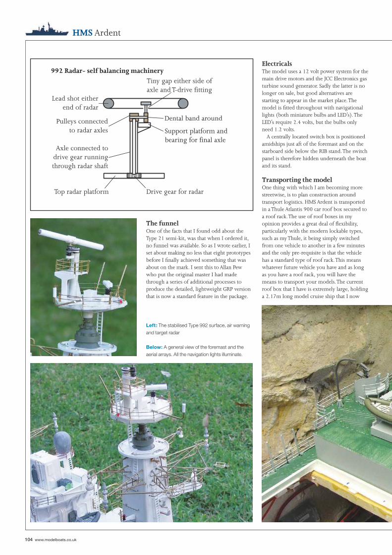
992 Radar- self balancing machinery
Dental band around
Support platform andbearing for final axle
Tiny gap either side ofaxle and T-drive fitting
Lead shot eitherend of radar
Pulleys connectedto radar axles
Axle connected todrive gear runningthrough radar shaft
Top radar platform Drive gear for radar
104 www.modelboats.co.uk
The funnelOne of the facts that I found odd about the Type 21 semi-kit, was that when I ordered it, no funnel was available. So as I wrote earlier, I set about making no less that eight prototypes before I fi nally achieved something that was about on the mark. I sent this to Allan Pew who put the original master I had made through a series of additional processes to produce the detailed, lightweight GRP version that is now a standard feature in the package.
HMS Ardent
Left: The stabilised Type 992 surface, air warning and target radar
Below: A general view of the foremast and the aerial arrays. All the navigation lights illuminate.
ElectricalsThe model uses a 12 volt power system for the main drive motors and the JCC Electronics gas turbine sound generator. Sadly the latter is no longer on sale, but good alternatives are starting to appear in the market place. The model is fi tted throughout with navigational lights (both miniature bulbs and LED’s). The LED’s require 2.4 volts, but the bulbs only need 1.2 volts.
A centrally located switch box is positioned amidships just aft of the foremast and on the starboard side below the RIB stand. The switch panel is therefore hidden underneath the boat and its stand.
Transporting the modelOne thing with which I am becoming more streetwise, is to plan construction around transport logistics. HMS Ardent is transported in a Thule Atlantis 900 car roof box secured to a roof rack. The use of roof boxes in my opinion provides a great deal of fl exibility, particularly with the modern lockable types, such as my Thule, it being simply switched from one vehicle to another in a few minutes and the only pre-requisite is that the vehicle has a standard type of roof rack. This means whatever future vehicle you have and as long as you have a roof rack, you will have the means to transport your models. The current roof box that I have is extremely large, holding a 2.17m long model cruise ship that I now
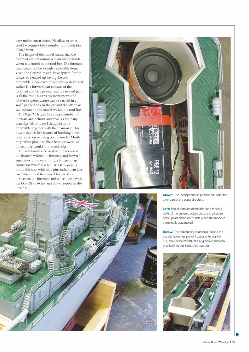
Model Boats Warships 105
have under construction. Needless to say, it could accommodate a number of models like HMS Ardent.
The height of the model means that the foremast section cannot remain on the model when it is stored in the roof box. The foremast itself could not be a single removable item, given the electronics and drive system for the radars, so I ended up having the two removable superstructure sections as described earlier. The forward part consists of the foremast and bridge area, and the second part is all the rest. This arrangement means the forward superstructure can be carried in a small padded box in the car and the after part can remain on the model within the roof box.
The Type 21 frigate has a large number of intricate and delicate antennae, as do many warships. All of these I designed to be removable together with the mainmast. This means there is less chance of breaking these features when working on the model. Mostly they either plug into their bases or swivel as indeed they would on the real ship.
The substantial electrical requirements of the features within the foremast and forward superstructure means using a bungee snap connector which is a bit like a Tamiya plug, but in this case with nine pins rather than just two. This is used to connect the electrical devices on the foremast and wheelhouse with the On/Off switches and power supply in the lower hull.
Above: The loudspeaker is positioned under the after part of the superstructure.
Left: The separation of the after and forward parts of the superstructure occurs at a natural break point and is not visible when the model is completely assembled.
Below: The substantial coamings around the access openings prevent water entering the hull, should the model take a ‘greenie’ and also positively locate the superstructure.
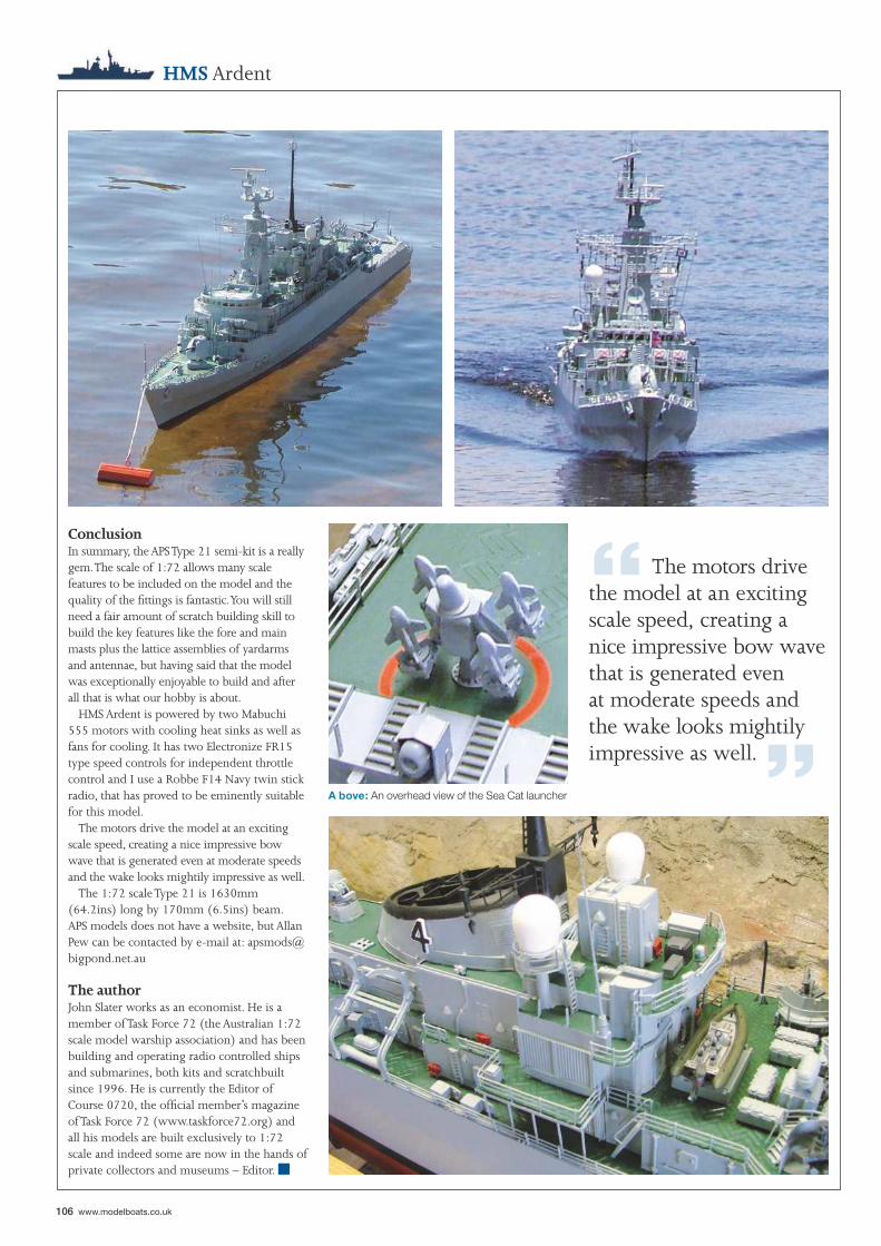
“ The motors drive the model at an exciting scale speed, creating a nice impressive bow wave that is generated even at moderate speeds and the wake looks mightily impressive as well. ”
106 www.modelboats.co.uk
HMS Ardent
ConclusionIn summary, the APS Type 21 semi-kit is a really gem. The scale of 1:72 allows many scale features to be included on the model and the quality of the fi ttings is fantastic. You will still need a fair amount of scratch building skill to build the key features like the fore and main masts plus the lattice assemblies of yardarms and antennae, but having said that the model was exceptionally enjoyable to build and after all that is what our hobby is about.
HMS Ardent is powered by two Mabuchi 555 motors with cooling heat sinks as well as fans for cooling. It has two Electronize FR15 type speed controls for independent throttle control and I use a Robbe F14 Navy twin stick radio, that has proved to be eminently suitable for this model.
The motors drive the model at an exciting scale speed, creating a nice impressive bow wave that is generated even at moderate speeds and the wake looks mightily impressive as well.
The 1:72 scale Type 21 is 1630mm (64.2ins) long by 170mm (6.5ins) beam. APS models does not have a website, but Allan Pew can be contacted by e-mail at: [email protected]
The authorJohn Slater works as an economist. He is a member of Task Force 72 (the Australian 1:72 scale model warship association) and has been building and operating radio controlled ships and submarines, both kits and scratchbuilt since 1996. He is currently the Editor of Course 0720, the offi cial member’s magazine of Task Force 72 (www.taskforce72.org) and all his models are built exclusively to 1:72 scale and indeed some are now in the hands of private collectors and museums – Editor.
A bove: An overhead view of the Sea Cat launcher
■

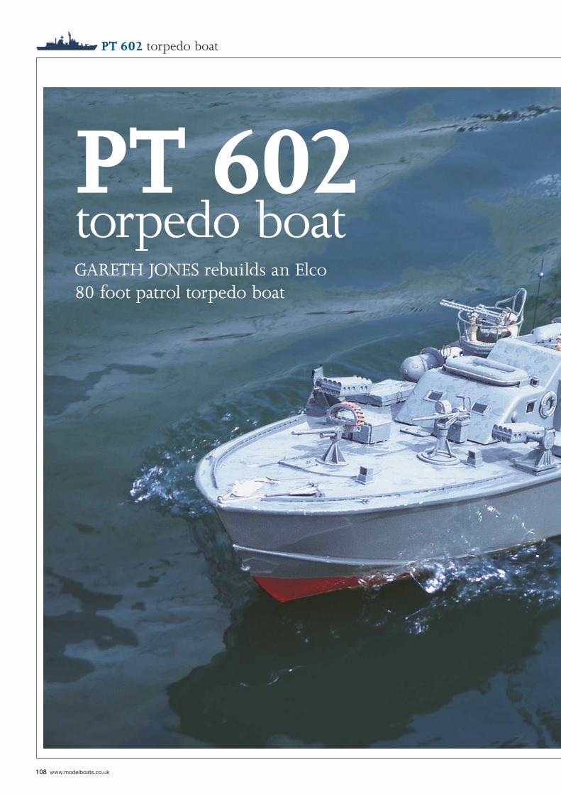
108 www.modelboats.co.uk
PT 602 torpedo boat
PT 602torpedo boatGARETH JONES rebuilds an Elco 80 foot patrol torpedo boat
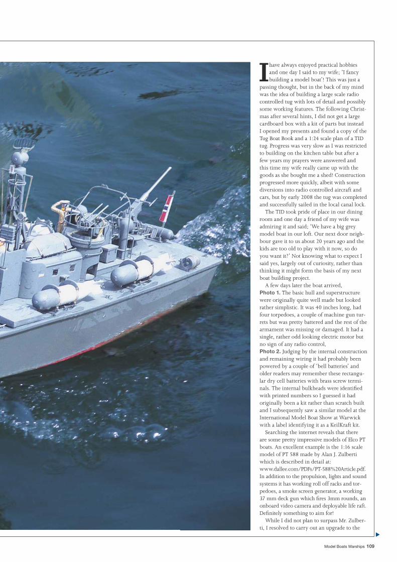
Model Boats Warships 109
I have always enjoyed practical hobbies and one day I said to my wife; ‘I fancy building a model boat’! This was just a
passing thought, but in the back of my mind was the idea of building a large scale radio controlled tug with lots of detail and possibly some working features. The following Christ-mas after several hints, I did not get a large cardboard box with a kit of parts but instead I opened my presents and found a copy of the Tug Boat Book and a 1:24 scale plan of a TID tug. Progress was very slow as I was restricted to building on the kitchen table but after a few years my prayers were answered and this time my wife really came up with the goods as she bought me a shed! Construction progressed more quickly, albeit with some diversions into radio controlled aircraft and cars, but by early 2008 the tug was completed and successfully sailed in the local canal lock.
The TID took pride of place in our dining room and one day a friend of my wife was admiring it and said; ‘We have a big grey model boat in our loft. Our next door neigh-bour gave it to us about 20 years ago and the kids are too old to play with it now, so do you want it?’ Not knowing what to expect I said yes, largely out of curiosity, rather than thinking it might form the basis of my next boat building project.
A few days later the boat arrived, Photo 1. The basic hull and superstructure were originally quite well made but looked rather simplistic. It was 40 inches long, had four torpedoes, a couple of machine gun tur-rets but was pretty battered and the rest of the armament was missing or damaged. It had a single, rather odd looking electric motor but no sign of any radio control, Photo 2. Judging by the internal construction and remaining wiring it had probably been powered by a couple of ‘bell batteries’ and older readers may remember these rectangu-lar dry cell batteries with brass screw termi-nals. The internal bulkheads were identifi ed with printed numbers so I guessed it had originally been a kit rather than scratch built and I subsequently saw a similar model at the International Model Boat Show at Warwick with a label identifying it as a KeilKraft kit.
Searching the internet reveals that there are some pretty impressive models of Elco PT boats. An excellent example is the 1:16 scale model of PT 588 made by Alan J. Zulberti which is described in detail at: www.dallee.com/PDFs/PT-588%20Article.pdf. In addition to the propulsion, lights and sound systems it has working roll off racks and tor-pedoes, a smoke screen generator, a working 37 mm deck gun which fi res 3mm rounds, an onboard video camera and deployable life raft. Defi nitely something to aim for!
While I did not plan to surpass Mr. Zulber-ti, I resolved to carry out an upgrade to the
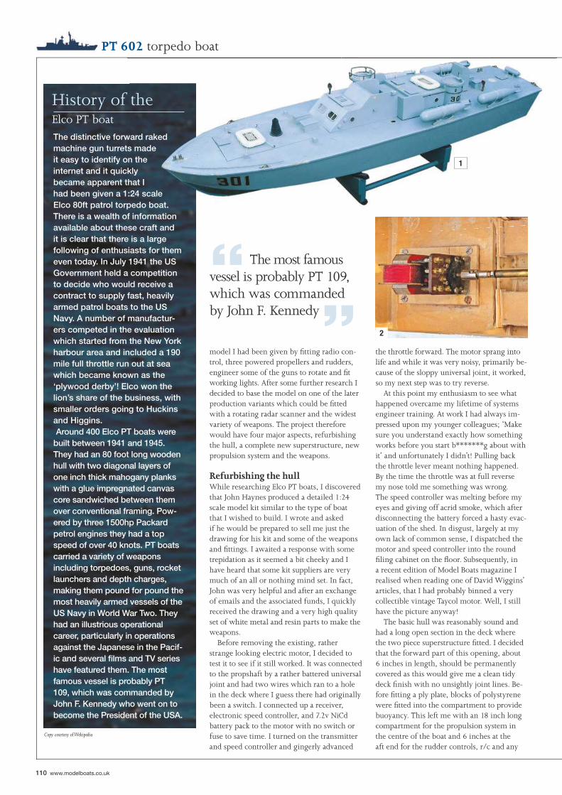
110 www.modelboats.co.uk
1
2
“ The most famous vessel is probably PT 109, which was commanded by John F. Kennedy”
History of the Elco PT boat
PT 602 torpedo boat
the throttle forward. The motor sprang into life and while it was very noisy, primarily be-cause of the sloppy universal joint, it worked, so my next step was to try reverse.
At this point my enthusiasm to see what happened overcame my lifetime of systems engineer training. At work I had always im-pressed upon my younger colleagues; ‘Make sure you understand exactly how something works before you start b*******g about with it’ and unfortunately I didn’t! Pulling back the throttle lever meant nothing happened. By the time the throttle was at full reverse my nose told me something was wrong. The speed controller was melting before my eyes and giving off acrid smoke, which after disconnecting the battery forced a hasty evac-uation of the shed. In disgust, largely at my own lack of common sense, I dispatched the motor and speed controller into the round fi ling cabinet on the fl oor. Subsequently, in a recent edition of Model Boats magazine I realised when reading one of David Wiggins’ articles, that I had probably binned a very collectible vintage Taycol motor. Well, I still have the picture anyway!
The basic hull was reasonably sound and had a long open section in the deck where the two piece superstructure fi tted. I decided that the forward part of this opening, about 6 inches in length, should be permanently covered as this would give me a clean tidy deck fi nish with no unsightly joint lines. Be-fore fi tting a ply plate, blocks of polystyrene were fi tted into the compartment to provide buoyancy. This left me with an 18 inch long compartment for the propulsion system in the centre of the boat and 6 inches at the aft end for the rudder controls, r/c and any
model I had been given by fi tting radio con-trol, three powered propellers and rudders, engineer some of the guns to rotate and fi t working lights. After some further research I decided to base the model on one of the later production variants which could be fi tted with a rotating radar scanner and the widest variety of weapons. The project therefore would have four major aspects, refurbishing the hull, a complete new superstructure, new propulsion system and the weapons.
Refurbishing the hullWhile researching Elco PT boats, I discovered that John Haynes produced a detailed 1:24 scale model kit similar to the type of boat that I wished to build. I wrote and asked if he would be prepared to sell me just the drawing for his kit and some of the weapons and fi ttings. I awaited a response with some trepidation as it seemed a bit cheeky and I have heard that some kit suppliers are very much of an all or nothing mind set. In fact, John was very helpful and after an exchange of emails and the associated funds, I quickly received the drawing and a very high quality set of white metal and resin parts to make the weapons.
Before removing the existing, rather strange looking electric motor, I decided to test it to see if it still worked. It was connected to the propshaft by a rather battered universal joint and had two wires which ran to a hole in the deck where I guess there had originally been a switch. I connected up a receiver, electronic speed controller, and 7.2v NiCd battery pack to the motor with no switch or fuse to save time. I turned on the transmitter and speed controller and gingerly advanced
The distinctive forward raked machine gun turrets made it easy to identify on the internet and it quickly became apparent that I had been given a 1:24 scale Elco 80ft patrol torpedo boat. There is a wealth of information available about these craft and it is clear that there is a large following of enthusiasts for them even today. In July 1941 the US Government held a competition to decide who would receive a contract to supply fast, heavily armed patrol boats to the US Navy. A number of manufactur-ers competed in the evaluation which started from the New York harbour area and included a 190 mile full throttle run out at sea which became known as the ‘plywood derby’! Elco won the lion’s share of the business, with smaller orders going to Huckins and Higgins.Around 400 Elco PT boats were
built between 1941 and 1945. They had an 80 foot long wooden hull with two diagonal layers of one inch thick mahogany planks with a glue impregnated canvas core sandwiched between them over conventional framing. Pow-ered by three 1500hp Packard petrol engines they had a top speed of over 40 knots. PT boats carried a variety of weapons including torpedoes, guns, rocket launchers and depth charges, making them pound for pound the most heavily armed vessels of the US Navy in World War Two. They had an illustrious operational career, particularly in operations against the Japanese in the Pacif-ic and several fi lms and TV series have featured them. The most famous vessel is probably PT 109, which was commanded by John F. Kennedy who went on to become the President of the USA.
Copy courtesy of Wekipedia
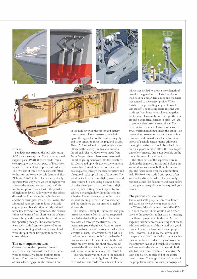
Model Boats Warships 111
3 4
5
6 7
which was drilled to allow a short length of dowel to be glued into it. This dowel was then held in a pillar drill chuck and the balsa was sanded to the correct profi le. When fi nished, the protruding length of dowel was cut off. The rotating radar antenna was made up from brass wire soldered together fl at for ease of assembly and then gently bent around a cylindrical former (a glass jam jar), to produce the correct curved shape. The drive motor is a small electric motor with a 500:1 gearbox mounted inside the cabin. The connection between motor and antenna is a thin brass rod, linked at each end by a short length of push fi t plastic tubing. Although the original radar mast could be folded back onto a support frame to allow the boat to pass under low bridges, this is not possible on the model because of the drive shaft.
The other parts of the superstructure in-cluding the engine air intake and Bofors gun ammunition rack were built up from sheet ply. The fabric cover over the ammunition rack, Photo 8 was made from a piece of an ancient handkerchief which had naturally reached a scale like fl exibility and even before painting was pretty close to the required grey colour.
The propulsion systemThe nearest scale propeller size was 30mm and based on my earlier experience with the TID tug I decided to use three MFA 457-RE540/1 motors. These would have a direct drive to the propellers rather than 6:1 gearing to a 70 mm propeller as in the tug. At this stage my inexperience was starting to show as I did not really know if this would be a good match of battery voltage, motor and prop size. However, I did know that it would fi t the space available. I decided to conduct a few tests in the bath in order to try and work out the optimum layout and weight distribution and eventually decided on two 6v4Ah, lead acid batteries connected in series to give 12v, with one battery at each end of the centre compartment. The original internal layout of the propulsion system was not photographed
in the hull covering the motor and battery compartment. The superstructure is built up on the upper half of the ladder using ply and strip timber to form the required shapes, Photo 5. Internal and navigation lights were fi tted and the wiring run to a connector at the aft end. The windows were made from 2mm Perspex sheet. I have never mastered the art of gluing windows into the structure as I always end up with glue on the windows themselves. Instead I cut the correct sized holes squarely through the superstructure and if required make up a frame of thin card. The window itself is then cut slightly oversize and then trimmed to size using a power fi le to chamfer the edges so that they form a slight taper. By trial fi tting them it is possible to achieve a neat tight fi t without the need for adhesive. The superstructure can be painted without needing to mask the transparency and the windows are just pressed in tightly afterwards.
The handrails along the cabin roof and gun turrets were made from brass rod supported in suitable sized split pins which locate in holes drilled through the structure. The instrument panel detail was found on an ex-cellent website: www.pt-boat.com, which has a wealth of useful information. For a while I tried without success, to fi nd a suitable ship’s boat to fi t on top of the cabin and in the end made my own from thin sheet ply. Since no internal details are visible this was quite easy and the end result is quite realistic, Photo 6.
The radar mast was built up to the required size from thin strips of ply, Photo 7. The fi xed radome was made from a bock of balsa
switches.I added spray strips to the hull sides using
3/32 inch square spruce. The towing eye and support plate, Photo 3, were made from a steel spring washer and a piece of brass sheet bonded to the hull with epoxy resin adhesive. The two sets of three engine exhausts fi tted to the transom were a notable feature of Elco PT boats, Photo 4. Each had a mechanically operated two-way valve which at high power allowed the exhaust to vent directly aft for minimum power loss but with the penalty of high noise levels. At low power, the valves directed the fl ow down through silencers and the exhaust gases exited underwater. The additional back pressure reduced available engine power but also signifi cantly reduced noise to allow stealthy operation. The exhaust valves were made from short lengths of 6mm brass tubing with brass wire bent to simulate the operating linkage. The silencer boxes were each made from two pieces of 6mm aluminium tubing glued together and fi lled with Milliput modelling putty to form the correct shape.
The new superstructureConstruction of the superstructure was relatively straightforward. The lower frame-work is essentially a ladder built up from 5mm x 25mm section pine. The lower half of this ladder engages in the main cut out
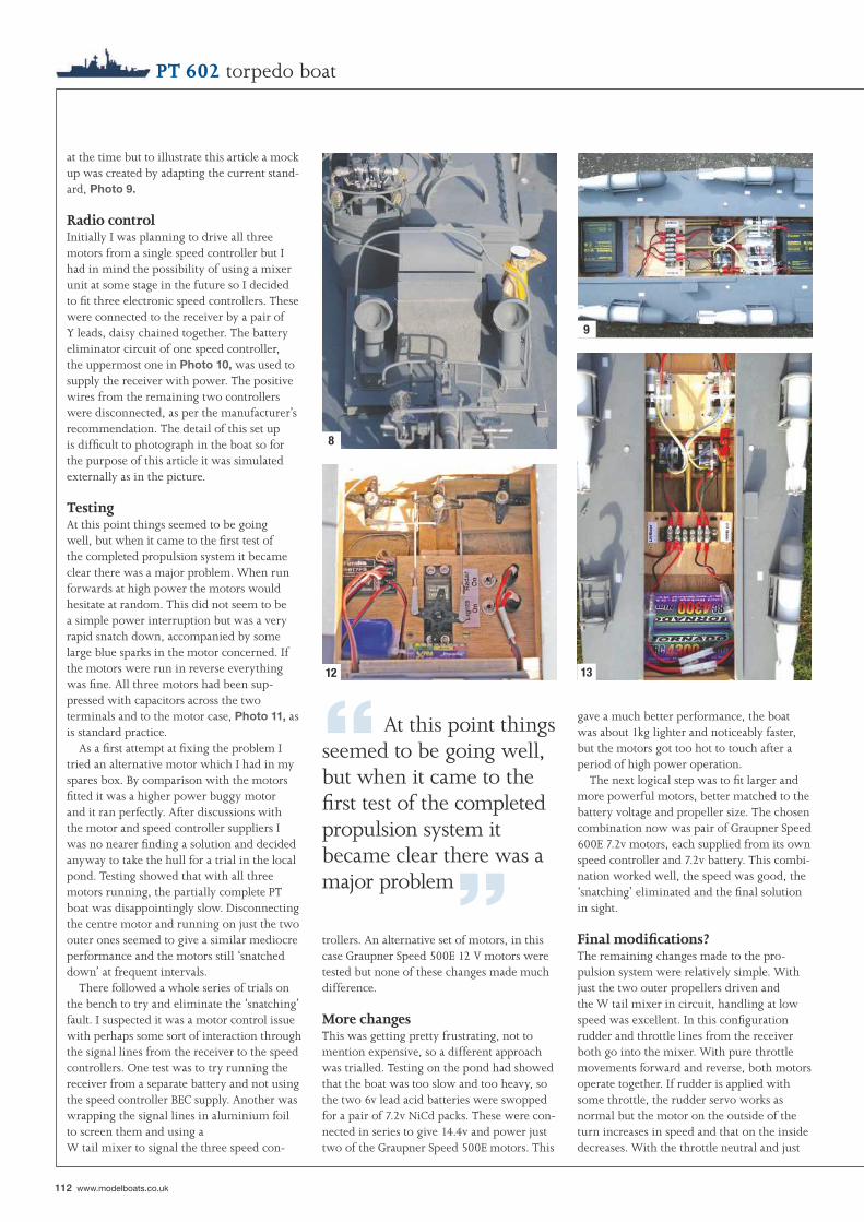
112 www.modelboats.co.uk
“ At this point things seemed to be going well, but when it came to the fi rst test of the completed propulsion system it became clear there was a major problem”
PT 602 torpedo boat
trollers. An alternative set of motors, in this case Graupner Speed 500E 12 V motors were tested but none of these changes made much difference.
More changesThis was getting pretty frustrating, not to mention expensive, so a different approach was trialled. Testing on the pond had showed that the boat was too slow and too heavy, so the two 6v lead acid batteries were swopped for a pair of 7.2v NiCd packs. These were con-nected in series to give 14.4v and power just two of the Graupner Speed 500E motors. This
at the time but to illustrate this article a mock up was created by adapting the current stand-ard, Photo 9.
Radio controlInitially I was planning to drive all three motors from a single speed controller but I had in mind the possibility of using a mixer unit at some stage in the future so I decided to fi t three electronic speed controllers. These were connected to the receiver by a pair of Y leads, daisy chained together. The battery eliminator circuit of one speed controller, the uppermost one in Photo 10, was used to supply the receiver with power. The positive wires from the remaining two controllers were disconnected, as per the manufacturer’s recommendation. The detail of this set up is diffi cult to photograph in the boat so for the purpose of this article it was simulated externally as in the picture.
TestingAt this point things seemed to be going well, but when it came to the fi rst test of the completed propulsion system it became clear there was a major problem. When run forwards at high power the motors would hesitate at random. This did not seem to be a simple power interruption but was a very rapid snatch down, accompanied by some large blue sparks in the motor concerned. If the motors were run in reverse everything was fi ne. All three motors had been sup-pressed with capacitors across the two terminals and to the motor case, Photo 11, as is standard practice.
As a fi rst attempt at fi xing the problem I tried an alternative motor which I had in my spares box. By comparison with the motors fi tted it was a higher power buggy motor and it ran perfectly. After discussions with the motor and speed controller suppliers I was no nearer fi nding a solution and decided anyway to take the hull for a trial in the local pond. Testing showed that with all three motors running, the partially complete PT boat was disappointingly slow. Disconnecting the centre motor and running on just the two outer ones seemed to give a similar mediocre performance and the motors still ‘snatched down’ at frequent intervals.
There followed a whole series of trials on the bench to try and eliminate the ‘snatching’ fault. I suspected it was a motor control issue with perhaps some sort of interaction through the signal lines from the receiver to the speed controllers. One test was to try running the receiver from a separate battery and not using the speed controller BEC supply. Another was wrapping the signal lines in aluminium foil to screen them and using a W tail mixer to signal the three speed con-
gave a much better performance, the boat was about 1kg lighter and noticeably faster, but the motors got too hot to touch after a period of high power operation.
The next logical step was to fi t larger and more powerful motors, better matched to the battery voltage and propeller size. The chosen combination now was pair of Graupner Speed 600E 7.2v motors, each supplied from its own speed controller and 7.2v battery. This combi-nation worked well, the speed was good, the ‘snatching’ eliminated and the fi nal solution in sight.
Final modifi cations?The remaining changes made to the pro-pulsion system were relatively simple. With just the two outer propellers driven and the W tail mixer in circuit, handling at low speed was excellent. In this confi guration rudder and throttle lines from the receiver both go into the mixer. With pure throttle movements forward and reverse, both motors operate together. If rudder is applied with some throttle, the rudder servo works as normal but the motor on the outside of the turn increases in speed and that on the inside decreases. With the throttle neutral and just
8
9
12 13
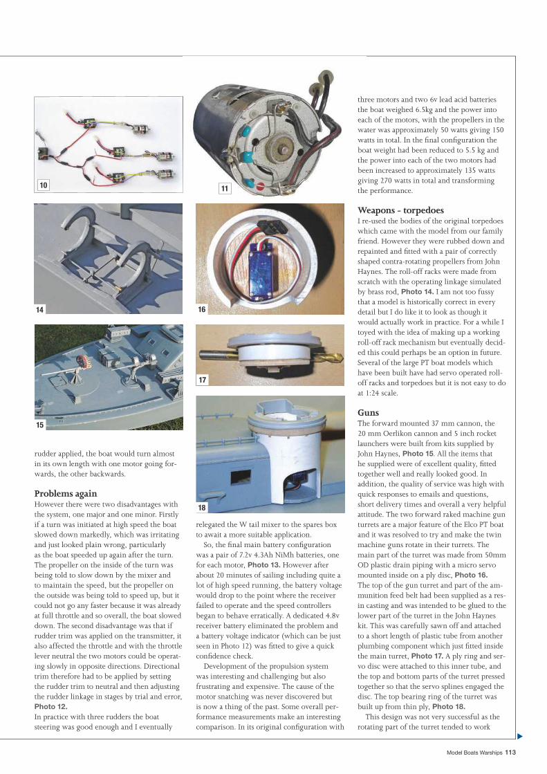
Model Boats Warships 113
three motors and two 6v lead acid batteries the boat weighed 6.5kg and the power into each of the motors, with the propellers in the water was approximately 50 watts giving 150 watts in total. In the fi nal confi guration the boat weight had been reduced to 5.5 kg and the power into each of the two motors had been increased to approximately 135 watts giving 270 watts in total and transforming the performance.
Weapons - torpedoesI re-used the bodies of the original torpedoes which came with the model from our family friend. However they were rubbed down and repainted and fi tted with a pair of correctly shaped contra-rotating propellers from John Haynes. The roll-off racks were made from scratch with the operating linkage simulated by brass rod, Photo 14. I am not too fussy that a model is historically correct in every detail but I do like it to look as though it would actually work in practice. For a while I toyed with the idea of making up a working roll-off rack mechanism but eventually decid-ed this could perhaps be an option in future. Several of the large PT boat models which have been built have had servo operated roll-off racks and torpedoes but it is not easy to do at 1:24 scale.
GunsThe forward mounted 37 mm cannon, the 20 mm Oerlikon cannon and 5 inch rocket launchers were built from kits supplied by John Haynes, Photo 15. All the items that he supplied were of excellent quality, fi tted together well and really looked good. In addition, the quality of service was high with quick responses to emails and questions, short delivery times and overall a very helpful attitude. The two forward raked machine gun turrets are a major feature of the Elco PT boat and it was resolved to try and make the twin machine guns rotate in their turrets. The main part of the turret was made from 50mm OD plastic drain piping with a micro servo mounted inside on a ply disc, Photo 16. The top of the gun turret and part of the am-munition feed belt had been supplied as a res-in casting and was intended to be glued to the lower part of the turret in the John Haynes kit. This was carefully sawn off and attached to a short length of plastic tube from another plumbing component which just fi tted inside the main turret, Photo 17. A ply ring and ser-vo disc were attached to this inner tube, and the top and bottom parts of the turret pressed together so that the servo splines engaged the disc. The top bearing ring of the turret was built up from thin ply, Photo 18.
This design was not very successful as the rotating part of the turret tended to work
rudder applied, the boat would turn almost in its own length with one motor going for-wards, the other backwards.
Problems againHowever there were two disadvantages with the system, one major and one minor. Firstly if a turn was initiated at high speed the boat slowed down markedly, which was irritating and just looked plain wrong, particularly as the boat speeded up again after the turn. The propeller on the inside of the turn was being told to slow down by the mixer and to maintain the speed, but the propeller on the outside was being told to speed up, but it could not go any faster because it was already at full throttle and so overall, the boat slowed down. The second disadvantage was that if rudder trim was applied on the transmitter, it also affected the throttle and with the throttle lever neutral the two motors could be operat-ing slowly in opposite directions. Directional trim therefore had to be applied by setting the rudder trim to neutral and then adjusting the rudder linkage in stages by trial and error, Photo 12. In practice with three rudders the boat steering was good enough and I eventually
relegated the W tail mixer to the spares box to await a more suitable application.
So, the fi nal main battery confi guration was a pair of 7.2v 4.3Ah NiMh batteries, one for each motor, Photo 13. However after about 20 minutes of sailing including quite a lot of high speed running, the battery voltage would drop to the point where the receiver failed to operate and the speed controllers began to behave erratically. A dedicated 4.8v receiver battery eliminated the problem and a battery voltage indicator (which can be just seen in Photo 12) was fi tted to give a quick confi dence check.
Development of the propulsion system was interesting and challenging but also frustrating and expensive. The cause of the motor snatching was never discovered but is now a thing of the past. Some overall per-formance measurements make an interesting comparison. In its original confi guration with
10 11
14
15
16
17
18
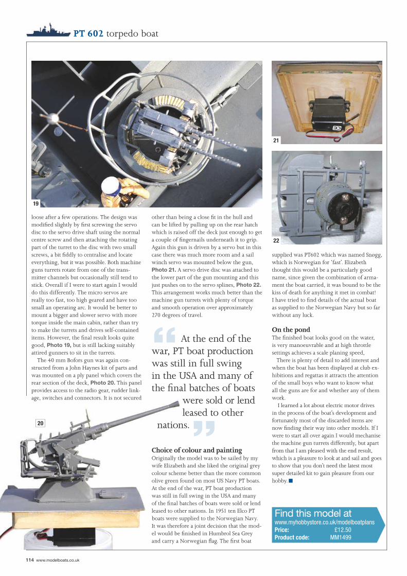
114 www.modelboats.co.uk
PT 602 torpedo boat
supplied was PT602 which was named Snøgg, which is Norwegian for ‘fast’. Elizabeth thought this would be a particularly good name, since given the combination of arma-ment the boat carried, it was bound to be the kiss of death for anything it met in combat! I have tried to fi nd details of the actual boat as supplied to the Norwegian Navy but so far without any luck.
On the pondThe fi nished boat looks good on the water, is very manoeuvrable and at high throttle settings achieves a scale planing speed, There is plenty of detail to add interest and when the boat has been displayed at club ex-hibitions and regattas it attracts the attention of the small boys who want to know what all the guns are for and whether any of them work.
I learned a lot about electric motor drives in the process of the boat’s development and fortunately most of the discarded items are now fi nding their way into other models. If I were to start all over again I would mechanise the machine gun turrets differently, but apart from that I am pleased with the end result, which is a pleasure to look at and sail and goes to show that you don’t need the latest most super detailed kit to gain pleasure from our hobby.
other than being a close fi t in the hull and can be lifted by pulling up on the rear hatch which is raised off the deck just enough to get a couple of fi ngernails underneath it to grip. Again this gun is driven by a servo but in this case there was much more room and a sail winch servo was mounted below the gun, Photo 21. A servo drive disc was attached to the lower part of the gun mounting and this just pushes on to the servo splines, Photo 22. This arrangement works much better than the machine gun turrets with plenty of torque and smooth operation over approximately 270 degrees of travel.
loose after a few operations. The design was modifi ed slightly by fi rst screwing the servo disc to the servo drive shaft using the normal centre screw and then attaching the rotating part of the turret to the disc with two small screws, a bit fi ddly to centralise and locate everything, but it was possible. Both machine guns turrets rotate from one of the trans-mitter channels but occasionally still tend to stick. Overall if I were to start again I would do this differently. The micro servos are really too fast, too high geared and have too small an operating arc. It would be better to mount a bigger and slower servo with more torque inside the main cabin, rather than try to make the turrets and drives self-contained items. However, the fi nal result looks quite good, Photo 19, but is still lacking suitably attired gunners to sit in the turrets.
The 40 mm Bofors gun was again con-structed from a John Haynes kit of parts and was mounted on a ply panel which covers the rear section of the deck, Photo 20. This panel provides access to the radio gear, rudder link-age, switches and connectors. It is not secured
19
20
21
22
“ At the end of the war, PT boat production was still in full swing in the USA and many of the fi nal batches of boats
were sold or lend leased to other
nations.”Choice of colour and paintingOriginally the model was to be sailed by my wife Elizabeth and she liked the original grey colour scheme better than the more common olive green found on most US Navy PT boats. At the end of the war, PT boat production was still in full swing in the USA and many of the fi nal batches of boats were sold or lend leased to other nations. In 1951 ten Elco PT boats were supplied to the Norwegian Navy. It was therefore a joint decision that the mod-el would be fi nished in Humbrol Sea Grey and carry a Norwegian fl ag. The fi rst boat
Find this model atwww.myhobbystore.co.uk/modelboatplansPrice: £12.50Product code: MM1499
■

We stock a wide range ofscale model ship card kits foryou to build including:Scale 1:200 - Full HullHMS Prince of Wales. . .£51.95HMS Naiad....................£36.95HMS Dragon.................£41.95HMS Matabele..............£25.95HMS Badsworth............£26.95HMS Campbeltown......£25.95HMS Lance....................£25.95HMS Dreadnought........£25.95HMAS Sydney...............£49.95USS Missouri.................£59.95USS Lexington CV-2.....£49.95Graf Spee.......................£29.95Tirpitz............................£58.95Admiral Hipper.............£45.95SMS Seydlitz..................£56.95SMS Szent Istvan..........£52.95
Scale 1:400 - WaterlineHMS King George V.....£12.95HMS Ajax......................£11.95HMS Exeter...................£11.95HMS Sheffield...............£10.95HMS Belfast..................£11.95HMS Roberts...................£8.95Raider Atlantis..............£18.95Bismarck........................£23.95Tirpitz............................£23.95Gneisenau......................£22.95Admiral Hipper.............£16.95Wilhelm Gustloff...........£23.95USS Iowa........................£25.95HIJMS Yamato.............£22.95
Scale 1:96 - Full HullHMS Victory.................£44.95HMB Endeavour...........£29.95
HMS Enterprize (1774) £35.95HMS Mercury (1779)....£43.95HMS Wolf (1752)..........£42.95Revenge (1588)..............£46.95Santa Leocadia (1777). .£29.95Lexington (1776)...........£29.95
Send your order withcheque/PO/credit card details toMarcle Models (MBWS),Turnagain, Finch Lane, Amer-sham, Bucks. HP7 9NE, Eng-land Tel/fax 01494-765910 (24hrs.) www.marcle.co.uk Pricesinclude UK P&P - overseas sur-charge per order: Europe £5,ROW £9. Send £4.50 (overseas£6.50 surface, £8.00 airmail) forour illustrated catalogue.*14-day “NO QUIBBLE”MONEY-BACK GUARAN-TEE (*if returned in a saleablecondition)
Book“Card Modelling - Basic &
Advanced Techniques”
Full colour illustrations.£17.95 inc. UK P&P,
Europe £22.95, ROW £25.95
116 www.modelboats.co.uk
inside of the desired turn. ‘Blipping’ this button allowed you to control the radius of the turn. If you have never used this method of steering before then have no fears as it is quite logical and ought to become second nature in a very short time, but then I started out with single channel r/c gear where ‘blipping’ had to used.
The transmitter had two buttons on the top of its case. One caused the turret to rotate left, the other to the right. There was also a small push button on the front of the case which caused the gun barrel to run through an up/down cycle. A small red bulb at the end of the barrel lights whilst doing this. Sorry, I almost forgot, two small headlights also operated when the tank was switched on.
Trials both inside the house when my wife was not looking, as well as outside, showed that
tank design of WW2 and is quoted to be 1/30 scale. It looked to be very accurate, perhaps not up to the standard of the more expensive military assembly kits, but a lot better than the ones I remember building in my youth. The tank came with a transmitter, small four cell rechargeable battery pack and a matching charging unit.
The instructions were just a double sided sheet of A4 paper. The text was half Chinese and half English, but thankfully was well illustrated with line drawings. After charging the battery pack, the model was tried out on the drive. The transmitter had two buttons on either side to control the tracks. Push the left button up and the tank moves forwards, pushing the button down gives reverse. The other button moves to the right or left and turns the model by stopping the track on the
LCT 6
I have long harboured a suspicion that magazine editors are appointed for their skill at placing subliminal ideas in the
heads of contributors. This seemed to be confi rmed, when travelling home after acting as a supervisor on a course at Oxford University, I took the opportunity to visit the Howes model shop in nearby Kidlington. Whilst in the shop I just had to buy a small r/c tank, my thoughts being: ‘Perfect for a working Land Craft Tank (LCT) model’. On walking out of the shop it suddenly dawned on me that our Editor had put this idea into my head some time previously.
The radio controlled tankEvery time I look at this small working model, it seems to become more impressive. The tank is based on the American Sherman M4 3A
LCT6GLYNN GUEST makes a semi-scaleGLYNN GUEST makes a semi-scalefree plan model based on a WW2 free plan model based on a WW2 tank landing crafttank landing craft
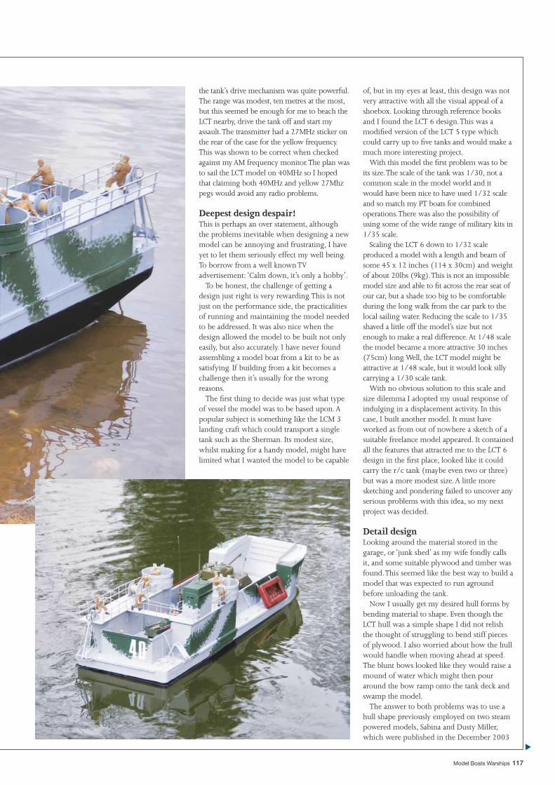
Model Boats Warships 117
the tank’s drive mechanism was quite powerful. The range was modest, ten metres at the most, but this seemed be enough for me to beach the LCT nearby, drive the tank off and start my assault. The transmitter had a 27MHz sticker on the rear of the case for the yellow frequency. This was shown to be correct when checked against my AM frequency monitor. The plan was to sail the LCT model on 40MHz so I hoped that claiming both 40MHz and yellow 27Mhz pegs would avoid any radio problems.
Deepest design despair!This is perhaps an over statement, although the problems inevitable when designing a new model can be annoying and frustrating, I have yet to let them seriously effect my well being. To borrow from a well known TV advertisement: ‘Calm down, it’s only a hobby’.
To be honest, the challenge of getting a design just right is very rewarding. This is not just on the performance side, the practicalities of running and maintaining the model needed to be addressed. It was also nice when the design allowed the model to be built not only easily, but also accurately. I have never found assembling a model boat from a kit to be as satisfying. If building from a kit becomes a challenge then it’s usually for the wrong reasons.
The fi rst thing to decide was just what type of vessel the model was to be based upon. A popular subject is something like the LCM 3 landing craft which could transport a single tank such as the Sherman. Its modest size, whilst making for a handy model, might have limited what I wanted the model to be capable
of, but in my eyes at least, this design was not very attractive with all the visual appeal of a shoebox. Looking through reference books and I found the LCT 6 design. This was a modifi ed version of the LCT 5 type which could carry up to fi ve tanks and would make a much more interesting project.
With this model the fi rst problem was to be its size. The scale of the tank was 1/30, not a common scale in the model world and it would have been nice to have used 1/32 scale and so match my PT boats for combined operations. There was also the possibility of using some of the wide range of military kits in 1/35 scale.
Scaling the LCT 6 down to 1/32 scale produced a model with a length and beam of some 45 x 12 inches (114 x 30cm) and weight of about 20lbs (9kg). This is not an impossible model size and able to fi t across the rear seat of our car, but a shade too big to be comfortable during the long walk from the car park to the local sailing water. Reducing the scale to 1/35 shaved a little off the model’s size but not enough to make a real difference. At 1/48 scale the model became a more attractive 30 inches (75cm) long. Well, the LCT model might be attractive at 1/48 scale, but it would look silly carrying a 1/30 scale tank.
With no obvious solution to this scale and size dilemma I adopted my usual response of indulging in a displacement activity. In this case, I built another model. It must have worked as from out of nowhere a sketch of a suitable freelance model appeared. It contained all the features that attracted me to the LCT 6 design in the fi rst place, looked like it could carry the r/c tank (maybe even two or three) but was a more modest size. A little more sketching and pondering failed to uncover any serious problems with this idea, so my next project was decided.
Detail designLooking around the material stored in the garage, or ‘junk shed’ as my wife fondly calls it, and some suitable plywood and timber was found. This seemed like the best way to build a model that was expected to run aground before unloading the tank.
Now I usually get my desired hull forms by bending material to shape. Even though the LCT hull was a simple shape I did not relish the thought of struggling to bend stiff pieces of plywood. I also worried about how the hull would handle when moving ahead at speed. The blunt bows looked like they would raise a mound of water which might then pour around the bow ramp onto the tank deck and swamp the model.
The answer to both problems was to use a hull shape previously employed on two steam powered models, Sabina and Dusty Miller, which were published in the December 2003
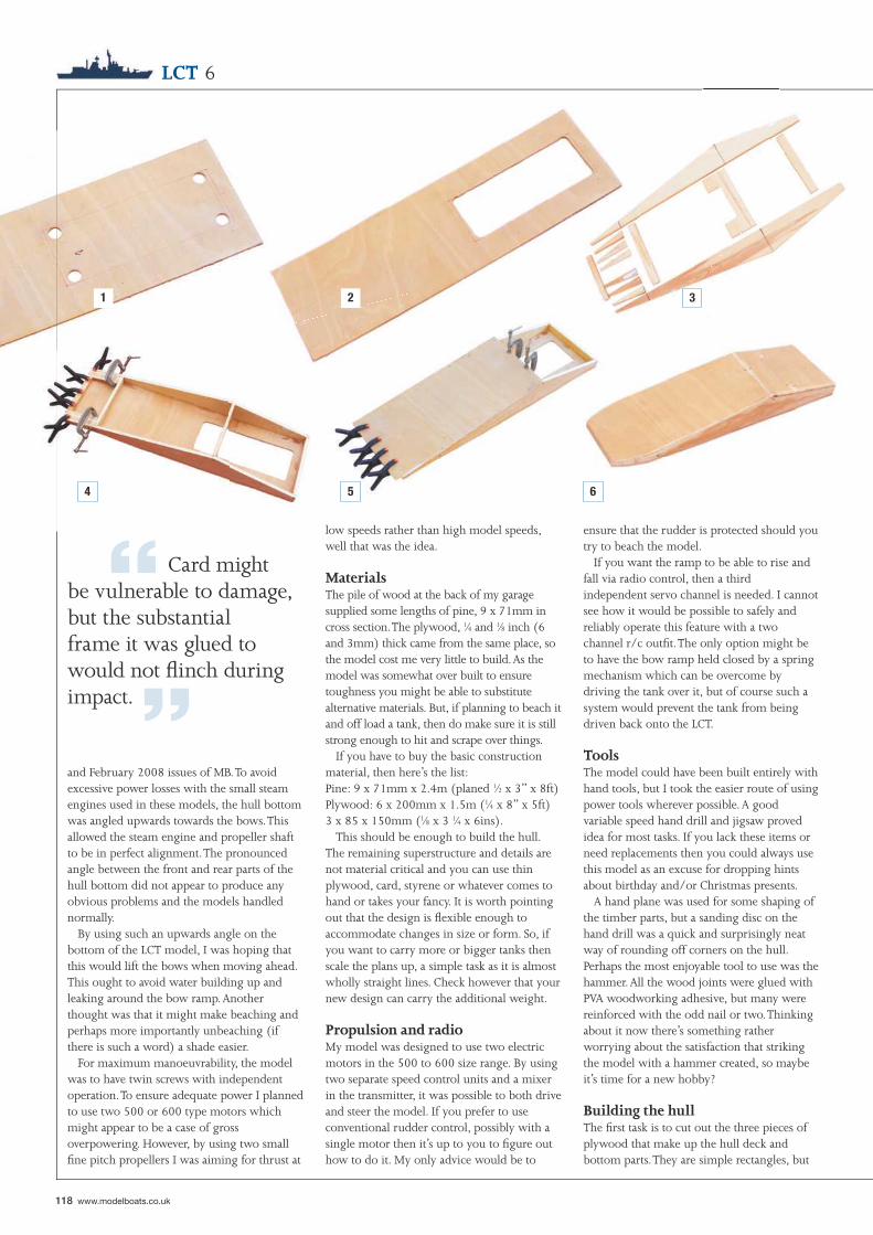
1 2 3
4 5 6
“ Card might be vulnerable to damage, but the substantial frame it was glued to would not fl inch during impact. ”
118 www.modelboats.co.uk
LCT 6
and February 2008 issues of MB. To avoid excessive power losses with the small steam engines used in these models, the hull bottom was angled upwards towards the bows. This allowed the steam engine and propeller shaft to be in perfect alignment. The pronounced angle between the front and rear parts of the hull bottom did not appear to produce any obvious problems and the models handled normally.
By using such an upwards angle on the bottom of the LCT model, I was hoping that this would lift the bows when moving ahead. This ought to avoid water building up and leaking around the bow ramp. Another thought was that it might make beaching and perhaps more importantly unbeaching (if there is such a word) a shade easier.
For maximum manoeuvrability, the model was to have twin screws with independent operation. To ensure adequate power I planned to use two 500 or 600 type motors which might appear to be a case of gross overpowering. However, by using two small fi ne pitch propellers I was aiming for thrust at
low speeds rather than high model speeds, well that was the idea.
MaterialsThe pile of wood at the back of my garage supplied some lengths of pine, 9 x 71mm in cross section. The plywood, 1⁄4 and 1⁄8 inch (6 and 3mm) thick came from the same place, so the model cost me very little to build. As the model was somewhat over built to ensure toughness you might be able to substitute alternative materials. But, if planning to beach it and off load a tank, then do make sure it is still strong enough to hit and scrape over things.
If you have to buy the basic construction material, then here’s the list:Pine: 9 x 71mm x 2.4m (planed 1⁄2 x 3” x 8ft)Plywood: 6 x 200mm x 1.5m (1⁄4 x 8” x 5ft)3 x 85 x 150mm (1⁄8 x 3 1⁄4 x 6ins).
This should be enough to build the hull. The remaining superstructure and details are not material critical and you can use thin plywood, card, styrene or whatever comes to hand or takes your fancy. It is worth pointing out that the design is fl exible enough to accommodate changes in size or form. So, if you want to carry more or bigger tanks then scale the plans up, a simple task as it is almost wholly straight lines. Check however that your new design can carry the additional weight.
Propulsion and radioMy model was designed to use two electric motors in the 500 to 600 size range. By using two separate speed control units and a mixer in the transmitter, it was possible to both drive and steer the model. If you prefer to use conventional rudder control, possibly with a single motor then it’s up to you to fi gure out how to do it. My only advice would be to
ensure that the rudder is protected should you try to beach the model.
If you want the ramp to be able to rise and fall via radio control, then a thirdindependent servo channel is needed. I cannot see how it would be possible to safely and reliably operate this feature with a two channel r/c outfi t. The only option might be to have the bow ramp held closed by a spring mechanism which can be overcome by driving the tank over it, but of course such a system would prevent the tank from being driven back onto the LCT.
ToolsThe model could have been built entirely with hand tools, but I took the easier route of using power tools wherever possible. A good variable speed hand drill and jigsaw proved idea for most tasks. If you lack these items or need replacements then you could always use this model as an excuse for dropping hints about birthday and/or Christmas presents.
A hand plane was used for some shaping of the timber parts, but a sanding disc on the hand drill was a quick and surprisingly neat way of rounding off corners on the hull. Perhaps the most enjoyable tool to use was the hammer. All the wood joints were glued with PVA woodworking adhesive, but many were reinforced with the odd nail or two. Thinking about it now there’s something rather worrying about the satisfaction that striking the model with a hammer created, so maybe it’s time for a new hobby?
Building the hullThe fi rst task is to cut out the three pieces of plywood that make up the hull deck and bottom parts. They are simple rectangles, but
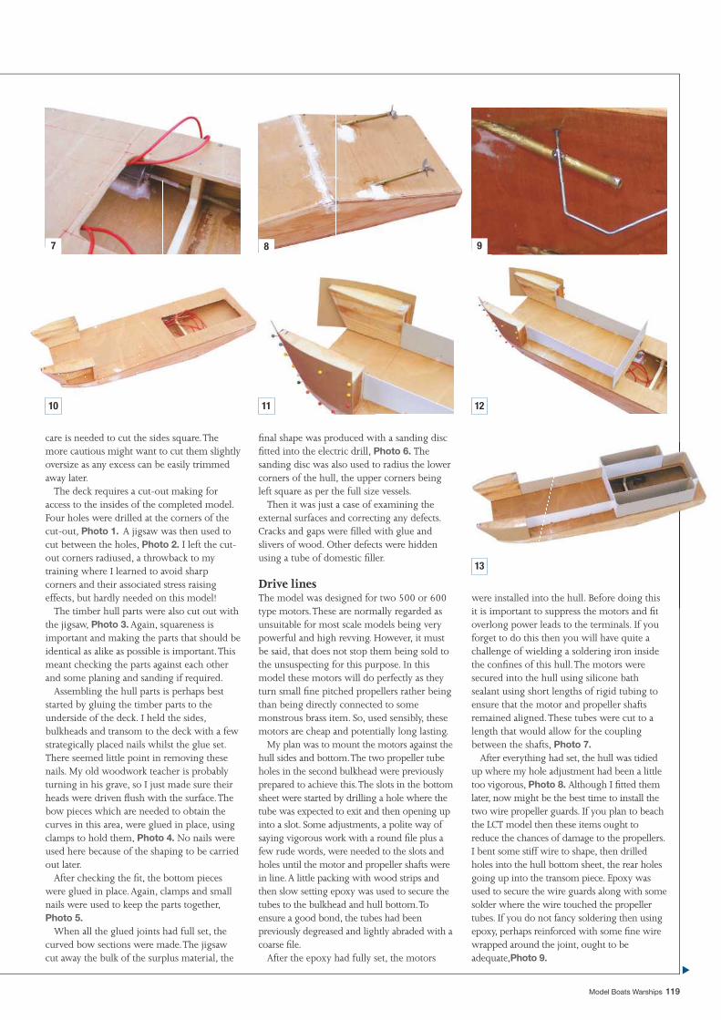
7 8 9
10 11 12
13
Model Boats Warships 119
care is needed to cut the sides square. The more cautious might want to cut them slightly oversize as any excess can be easily trimmed away later.
The deck requires a cut-out making for access to the insides of the completed model. Four holes were drilled at the corners of the cut-out, Photo 1. A jigsaw was then used to cut between the holes, Photo 2. I left the cut-out corners radiused, a throwback to my training where I learned to avoid sharp corners and their associated stress raising effects, but hardly needed on this model!
The timber hull parts were also cut out with the jigsaw, Photo 3. Again, squareness is important and making the parts that should be identical as alike as possible is important. This meant checking the parts against each other and some planing and sanding if required.
Assembling the hull parts is perhaps best started by gluing the timber parts to the underside of the deck. I held the sides, bulkheads and transom to the deck with a few strategically placed nails whilst the glue set. There seemed little point in removing these nails. My old woodwork teacher is probably turning in his grave, so I just made sure their heads were driven fl ush with the surface. The bow pieces which are needed to obtain the curves in this area, were glued in place, using clamps to hold them, Photo 4. No nails were used here because of the shaping to be carried out later.
After checking the fi t, the bottom pieces were glued in place. Again, clamps and small nails were used to keep the parts together, Photo 5.
When all the glued joints had full set, the curved bow sections were made. The jigsaw cut away the bulk of the surplus material, the
fi nal shape was produced with a sanding disc fi tted into the electric drill, Photo 6. The sanding disc was also used to radius the lower corners of the hull, the upper corners being left square as per the full size vessels.
Then it was just a case of examining the external surfaces and correcting any defects. Cracks and gaps were fi lled with glue and slivers of wood. Other defects were hidden using a tube of domestic fi ller.
Drive linesThe model was designed for two 500 or 600 type motors. These are normally regarded as unsuitable for most scale models being very powerful and high revving. However, it must be said, that does not stop them being sold to the unsuspecting for this purpose. In this model these motors will do perfectly as they turn small fi ne pitched propellers rather being than being directly connected to some monstrous brass item. So, used sensibly, these motors are cheap and potentially long lasting.
My plan was to mount the motors against the hull sides and bottom. The two propeller tube holes in the second bulkhead were previously prepared to achieve this. The slots in the bottom sheet were started by drilling a hole where the tube was expected to exit and then opening up into a slot. Some adjustments, a polite way of saying vigorous work with a round fi le plus a few rude words, were needed to the slots and holes until the motor and propeller shafts were in line. A little packing with wood strips and then slow setting epoxy was used to secure the tubes to the bulkhead and hull bottom. To ensure a good bond, the tubes had been previously degreased and lightly abraded with a coarse fi le.
After the epoxy had fully set, the motors
were installed into the hull. Before doing this it is important to suppress the motors and fi t overlong power leads to the terminals. If you forget to do this then you will have quite a challenge of wielding a soldering iron inside the confi nes of this hull. The motors were secured into the hull using silicone bath sealant using short lengths of rigid tubing to ensure that the motor and propeller shafts remained aligned. These tubes were cut to a length that would allow for the coupling between the shafts, Photo 7.
After everything had set, the hull was tidied up where my hole adjustment had been a little too vigorous, Photo 8. Although I fi tted them later, now might be the best time to install the two wire propeller guards. If you plan to beach the LCT model then these items ought to reduce the chances of damage to the propellers. I bent some stiff wire to shape, then drilled holes into the hull bottom sheet, the rear holes going up into the transom piece. Epoxy was used to secure the wire guards along with some solder where the wire touched the propeller tubes. If you do not fancy soldering then using epoxy, perhaps reinforced with some fi ne wire wrapped around the joint, ought to be adequate,Photo 9.
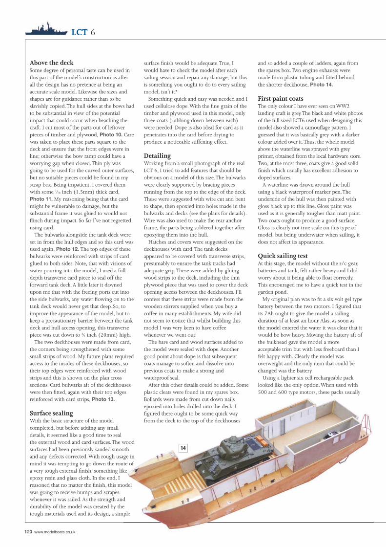
14
120 www.modelboats.co.uk
LCT 6
Above the deckSome degree of personal taste can be used in this part of the model’s construction as after all the design has no pretence at being an accurate scale model. Likewise the sizes and shapes are for guidance rather than to be slavishly copied. The hull sides at the bows had to be substantial in view of the potential impact that could occur when beaching the craft. I cut most of the parts out of leftover pieces of timber and plywood, Photo 10. Care was taken to place these parts square to the deck and ensure that the front edges were in line; otherwise the bow ramp could have a worrying gap when closed. Thin ply was going to be used for the curved outer surfaces, but no suitable pieces could be found in my scrap box. Being impatient, I covered them with some 1⁄16 inch (1.5mm) thick card, Photo 11. My reasoning being that the card might be vulnerable to damage, but the substantial frame it was glued to would not fl inch during impact. So far I’ve not regretted using card.
The bulwarks alongside the tank deck were set in from the hull edges and so this card was used again, Photo 12. The top edges of these bulwarks were reinforced with strips of card glued to both sides. Note, that with visions of water pouring into the model, I used a full depth transverse card piece to seal off the forward tank deck. A little later it dawned upon me that with the freeing ports cut into the side bulwarks, any water fl owing on to the tank deck would never get that deep. So, to improve the appearance of the model, but to keep a precautionary barrier between the tank deck and hull access opening, this transverse piece was cut down to 3⁄4 inch (20mm) high.
The two deckhouses were made from card, the corners being strengthened with some small strips of wood. My future plans required access to the insides of these deckhouses, so their top edges were reinforced with wood strips and this is shown on the plan cross sections. Card bulwarks aft of the deckhouses were then fi tted, again with their top edges reinforced with card strips, Photo 13.
Surface sealingWith the basic structure of the model completed, but before adding any small details, it seemed like a good time to sealthe external wood and card surfaces. The wood surfaces had been previously sanded smooth and any defects corrected. With rough usage in mind it was tempting to go down the route of a very tough external fi nish, something like epoxy resin and glass cloth. In the end, I reasoned that no matter the fi nish, this model was going to receive bumps and scrapes whenever it was sailed. As the strength and durability of the model was created by the tough materials used and its design, a simple
surface fi nish would be adequate. True, I would have to check the model after each sailing session and repair any damage, but this is something you ought to do to every sailing model, isn’t it?
Something quick and easy was needed and I used cellulose dope. With the fi ne grain of the timber and plywood used in this model, only three coats (rubbing down between each) were needed. Dope is also ideal for card as it penetrates into the card before drying to produce a noticeable stiffening effect.
DetailingWorking from a small photograph of the real LCT 6, I tried to add features that should be obvious on a model of this size. The bulwarks were clearly supported by bracing pieces running from the top to the edge of the deck. These were suggested with wire cut and bent to shape, then epoxied into holes made in the bulwarks and decks (see the plans for details). Wire was also used to make the rear anchor frame, the parts being soldered together after epoxying them into the hull.
Hatches and covers were suggested on the deckhouses with card. The tank decks appeared to be covered with transverse strips, presumably to ensure the tank tracks had adequate grip. These were added by gluing wood strips to the deck, including the thin plywood piece that was used to cover the deck opening access between the deckhouses. I’ll confess that these strips were made from the wooden stirrers supplied when you buy a coffee in many establishments. My wife did not seem to notice that whilst building this model I was very keen to have coffee whenever we went out!
The bare card and wood surfaces added to the model were sealed with dope. Another good point about dope is that subsequent coats manage to soften and dissolve into previous coats to make a strong and waterproof seal.
After this other details could be added. Some plastic cleats were found in my spares box. Bollards were made from cut down nails epoxied into holes drilled into the deck. I fi gured there ought to be some quick way from the deck to the top of the deckhouses
and so added a couple of ladders, again from the spares box. Two engine exhausts were made from plastic tubing and fi tted behind the shorter deckhouse, Photo 14.
First paint coatsThe only colour I have ever seen on WW2 landing craft is grey. The black and white photos of the full sized LCT6 used when designing this model also showed a camoufl age pattern. I guessed that it was basically grey with a darker colour added over it. Thus, the whole model above the waterline was sprayed with grey primer, obtained from the local hardware store. Two, at the most three, coats give a good solid fi nish which usually has excellent adhesion to doped surfaces.
A waterline was drawn around the hull using a black waterproof marker pen. The underside of the hull was then painted with gloss black up to this line. Gloss paint was used as it is generally tougher than matt paint. Two coats ought to produce a good surface. Gloss is clearly not true scale on this type of model, but being underwater when sailing, it does not affect its appearance.
Quick sailing testAt this stage, the model without the r/c gear, batteries and tank, felt rather heavy and I did worry about it being able to fl oat correctly. This encouraged me to have a quick test in the garden pond.
My original plan was to fi t a six volt gel type battery between the two motors. I fi gured that its 7Ah ought to give the model a sailing duration of at least an hour. Alas, as soon as the model entered the water it was clear that it would be bow heavy. Moving the battery aft of the bulkhead gave the model a more acceptable trim but with less freeboard than I felt happy with. Clearly the model was overweight and the only item that could be changed was the battery.
Using a lighter six cell rechargeable pack looked like the only option. When used with 500 and 600 type motors, these packs usually
15 16
“ Once I could stop hopping around due to burnt fi ngertips (I always forget how good a conductor of heat copper is when trying to hold parts together) these items were sprayed with the grey primer. ”
Movement of freeend of cord
Movement of arm
Fixed endof cord
Lever arm
Pivot
Cord secured to ramp Hook Spring Servo
Plastic tube Hole for cord
Figure 1.
Figure 2.
Model Boats Warships 121
offer high performance, but of relatively short duration. Using a pack to power two such motors looked very unpromising at fi rst, but in fact three things made them very suitable for this model.
First, the two motors were lightly loaded and should draw nothing like the current demanded in a fast electric model. The second point was that the LCT model would spend most of its time cruising at modest speeds rather than charging about at full speed. Last, the capacity of NiMH cells has increased dramatically over the past few years, whilst the prices have fallen.
A 3300mAh pack was fi tted into the rear of the hull up against the inner face of the transom. With the two speed controllers and the receiver between it and the bulkhead, the model had perfect trim without the need for any ballast. Holding the model back and applying full power revealed plenty of urge from the drive lines that must have disturbed whatever lives at the bottom of our pond. Thus encouraged, I was able to proceed to complete the model.
Deckhouse topsThe two deckhouses were covered with detachable roofs made from thin plywood. The frameworks which plug into the deckhouse openings were made inside these openings before gluing to the underside of the detachable roofs. This ensures a good and secure fi t into the openings. Note that the port roof extends rearwards to the stern anchor frame.
The protected steering position on the starboard roof was just made from a simple cardboard box. The vision slits on the full size vessels appeared to be made through some external reinforcement strips which was suggested by card strips on the model. A card access hatch was added to the read of the steering position.
Both deckhouses feature a circular gun positions. I looked in one of the scrap boxes and found an empty cotton bud container which was perfect for the job. The addition of a couple of card reinforcing bands and they looked just the part.
The catwalk between the two roofs over the tank deck was a problem. Rather than have it as a separate item, which might be prone to damage, I glued one end securely to the port roof. The other end was to fi t under the starboard deckhouse roof edge, Photo 15. This is much safer, as long as I remember to lift the starboard roof off before the port one! All the external surfaces were then sealed with a couple of coats of dope.
Railings are an item on any model that I willingly confess to hate making. Luckily for me this model only required railings around the edges of the deckhouse roofs and the
catwalk. Soft copper wire, removed from spare lengths of domestic cabling, is my preferred material for railings. It is easy to straighten; you just clamp one end in the bench vice and pull the other with pliers until it ‘gives’ (extending beyond the yield point for the more technically minded), but do remember to wear eye protection in case something breaks. It is easy to bend, as pure copper has little ‘spring back’ meaning you do not have to bend it past the fi nal angle you require. If a mistake is made it can be straightened again by using the above process. Strong railings can be quickly made by soldering the copper parts together. Finally, one son-in-law is an electrician, so I am never going to be short of this material!
The railing uprights were made from ‘L’ shaped pieces of copper wire. These were secured with epoxy into notches cut around the edges of the roofs and holes in the frameworks on the roof undersides. The uprights on the catwalk were ‘U’ shaped, again fi tting into notches and secured with epoxy. After the epoxy had set, the rails were soldered to the uprights, Photo 16. Once I could stop hopping around due to burnt fi ngertips (I always forget how good a conductor of heat copper is when trying to hold parts together) these items were sprayed with the grey primer to match the rest of the model.
The rampThis was a novel feature for me. The actual ramp was just going to be a piece of 1⁄8 inch (3mm) thick plywood, hinged at the bottom to be level with the tank deck. I was hoping that, being angled forwards from the hinge, the ramp would fall down under its own weight. Lifting it back up was going to be the problem.
The fi rst idea was to use something like a motor with a gear reduction attached. I had an old r/c yacht sailwinch somewhere in a drawer. This certainly had more than enough power, too much so I felt after a moments thought. This gave me images of the ramp becoming
18
122 www.modelboats.co.uk
LCT 6
jammed and the sailwinch continuing to pull until something broke, probably accompanied by expensive noises. Another problem was that such an item would have had to be installed inside the hull which was getting crowded and could do without adding a complex linkage between winch and ramp.
A standard servo ought to have more than enough power to raise the ramp. It could be installed inside one of the deckhouses and have a simple direct link to the ramp. My response of ‘problem solved’ proved to be premature when it was realised that a normal servo arm would not have enough travel to raise the ramp unless it was attached closer to the hinge than I felt desirable. The obvious solution of extending a servo arm was limited by the internal width of the deckhouse. The equally obvious idea of turning a servo onto its side was also a non-starter due to the width of the deckhouses.
My radio control yachting experience came to the rescue as the total movement of the sheets, which control the position of the sails, could be increased by doubling the cord back through a hole in the servo arm to a fi xed point, Figure 1. A few experiments showed that this method produced the right amount of movement to raise the ramp. The fi nal method used is shown in Figure 2. The spring was included to allow some ‘give’ in the system and ensure that the cord remainedin tension when the ramp was closed without stalling the servo. The servo arm was extended by using a safety pin, cut and bent to fi t into the servo disc holes then secured with a small screw. A stainless steel safety pin has the necessary strength and having a smooth hard surface, allows the cord to slide with little friction.
The ramp servo was secured to two balsa crosspieces glued between the deckhouse sides. A cup-hook was secured into a wood block glued inside the deckhouse. The cord exits the deckhouse via a hole, passes along the side of the bulwark, then through a plastic tube fi tted through the bow pieces. Your aim should be to keep the path of this cord as straight as possible, so it is a case of ‘eyeballing’ and rechecking before drilling any holes.
Hinge hiccupI was going to use a couple of brass hinges to secure the ramp to the hull. Searching through the box in which I drop all my hinges and I found two possible candidates. I then tried to fi gure out just how to fi t the hinges and came to the conclusion that it was going to be very diffi cult to avoid having a gap between the bows and ramp, which was just not what was needed. It also became clear that unless the two hinges were perfectly aligned, the ramp was unlikely to fall open under its own weight.
Inspiration often seems to come from out of
nowhere, but in this case I knew the origin. As I pondered the hinge problem, my eyes fell on a roll of duct tape. Immediately my memory of building a small remote controlled vessel for a Royal Navy and Young Engineers competition sprang into life. This vessel had used such tape to make a simple hinged ramp essential for the oil skimming task it was designed carry out. A strip of tape was cut and pressed onto the inner face of the ramp and tank deck and a free moving but watertight hinge was made.
Now knowing that the method would work, the ramp was then removed and sealed with three coats of dope. Transverse strips, as added to the tank deck, were glued across the ramp taking care not to fi x them where the tape was to be applied. The ramp was sprayed with grey primmer to match the model before sticking it back in place with a fresh piece of duct tape. By the way, I used some silver tape which much to my surprise blended remarkably well with the primer, Photo 17.
A 1⁄16 inch (1.5mm) diameter hole was drilled through the ramp to match where the cord came out of the tube in the bows. The cord was threaded through this hole and a loose knot made. There then followed a bout of adjustments to the knot position until the servo was able to raise and lower the ramp properly. In the end the ramp, due to the spring, would close with a reassuring ‘snap’.
Final fi nishingThe photographs I was using as reference material shows the full size LCT6 displaying a camoufl age pattern. I decided to reproduce this with patches of matt green paint, the edges being mottled to merge into the grey.
Most landing craft appeared to have some identifying number on their bows. I found some suitable self-adhesive numbers, but hand painted numbers might have been a shade more realistic for these wartime vessels. Vision slots in the enclosed conning position could be painted or even drawn on with a waterproof pen.
The fi nal fi nishing act was to spray the whole model with a couple of coats of clear satin varnish. I use a spray can and lightly dust over the model with the varnish to avoid any excessive build up and possible reaction with the previously applied paints.
Final detailsLanding craft carried a large anchor at the stern which could be dropped before beaching the vessel. This allowed the LCT to be kedged off using the onboard winch. It was hard to fi gure out the actual shape of these kedge anchors, but a reasonable looking anchor and winch were made from plastic and wire.
The two gun positions each required a 20mm gun. Again I just made up something
that looked appropriate from plastic sheet and tubing. A couple of ammunition boxes were made from scrap wood and sealed with dope.
The paint fi nish for these items was just the same as for the model, grey and satin varnish sprays and it is easier to do this before sticking them onto the model. I usually fi x them onto one end of a strip of wood with some Blu-tack or something similar. This allows you to hold the other end whilst spraying, very handy for getting the paint into all the corners.
I could see liferafts on the full size LCT’s, so a couple were made for the model. Nothing elaborate, just balsa strip to make the outline and the edges given a small radius. After sealing with dope, a mesh from plastic strip was glued to the bottom. As for the colour of the life rafts, bright yellow or orange seemed out of place on a camoufl aged military vessel. A dull tan colour, further dulled with matt black streaks, was eventually used. The rafts were then glued to the bulwark supports, taking care to avoid fouling the ramp cord.
A simple pole mast could be seen on the roof of the steering position of the LCT6 design. This was made from brass tubing which extended down to the underside of the detachable hatch. The mast was doing to be part of the receiver aerial wire.
Still emptyEven with the tank on board, the model still looked empty and lifeless. Clearly a crew was needed and something to fi ll the empty space behind the tank. This lead me towards the plastic military kit section of a local hobby store.
The range and quality of these kits was very impressive to someone who remembers buying one of the fi rst Airfi x kits from Woolworths, but and there is usually a ‘but’ lurking somewhere in my modelling activities, some of the vehicle kits were more expensive than the r/c tank that started me building this model in the fi rst place. I’m going to suggest
“ The jeep and associated fi gures were glued to the detachable cover over the hull access opening. As this area still looked a little bare, some cargo in the form of oil drums and ammunition boxes were added. ”
19
17
Model Boats Warships 123
that if you plan to build a landing craft model which carries more than one tank, then you might consider buying extra r/c tanks. Not only might this be cheaper, just think of the sight of the LCT beaching and two or three tanks being driven ashore!
After searching through what seemed like hundreds of plastic kits, I settled on the Italeri Jeep and trailer kit (No. 314). It included three fi gures, but clearly more crew were needed for this model. Numerous fi gure sets were available in 1/35 scale, but they usually seemed to have only two or three fi gures in them. A quick bit of mental arithmetic showed that this was going to make it expensive to produce a busy looking model. Then my eyes fell upon the Tamiya US Infantry set (item no. 35048**900). This contained eight fi gures and their equipment, all of which looked suitable for the LCT model and even better was the price of less than £3.
Armed with these two kits, a couple of days were spent in the workshop planning, building and painting. After some experimentation, the jeep was built with its hood open with a group of soldiers working on some mechanical problem. This allowed me to use one fi gure who was supposed to be laying on his stomach and ready to fi re his rifl e. He was rotated through 180 degrees to become the poor chap laying on his back and working under the jeep whilst others looked on. Other fi gures were positioned to suggest working on the two guns and getting the anchor winch and cable prepared. All of this required some swapping and adjustments of their limbs. The one that worked especially
well was a soldier caught walking, somewhat apprehensively, across the catwalk.
The jeep and associated fi gures were glued to the detachable cover over the hull access opening. As this area still looked a little bare, some cargo in the form of oil drums and ammunition boxes was added, Photo 18. These items were glued in place, save for one oil drum which I secured with a screw from under the deck. This gave me a secure and convenient way to lift the deck off the model without damaging anything. As a fi nal touch a fi gure was seated nonchalantly on the boxes of ammunition!
Re-installing the r/c gearA proper tidy installation was needed rather than the quick lash-up that was used in the earlier pond test. Over the years I’ve found that using a block of foam plastic with cut-outs to match receivers and speed controllers to be very convenient. Using slightly undersize cut-outs, items are held securely when sailing, but it still allows for their easy removal.
I used the layout shown on the plans, Photo 19. Holes had to be drilled through the deck inside both deckhouses. One hole was for the ramp servo lead, the other for the receiver aerial wire. Whilst you could easily hide a fl exible aerial wire on the tank deck, I always like to use a vertical whip whenever possible. This keeps the aerial away from sources of internal interference, usually electric motors, and exposes it to a stronger signal from the transmitter. It also avoids any directional effects when sailing.
In the LCT model, the aerial was connected to the bottom of the brass tube mast with a small plug and matching socket. A length of fi ne wire, about 12 inches (300mm) long is plugged into the top of the brass tube whenever sailing. This fi ne wire is usually invisible but must have a safety loop bent at its top end. The total length of the new aerial system ought to be as close to the original fl exible aerial wire as possible. This requires the original aerial to be shortened before soldering to the plug and socket.
It’s a good idea to make the electrical wiring inside this or for that matter any model, as tidy as possible. This makes it less likely to foul any moving parts like motor couplings. It also makes trouble shooting much easier when and if problems occur!
Sailing properlyI usually make out a ‘gripe sheet’ during the sailing trials of any new model. This is a list of problems, peculiarities, idiosyncrasies or whatever that needs to be sorted before the next sailing session. By writing it down I do not forget things on the journey home. More likely is that I remember that the model displayed a list, but I then forget which side was low.
I can honestly say that this model’s gripe list was blank, with nothing needing to be corrected. It might be nice to think that this was due to innate genius on my part, but reality suggests that I’ve just learnt from all my past mistakes. No doubt the next model will contain some new mistakes for me to make.
After carefully checking the controls were correctly orientated, the model was moved
■
124 www.modelboats.co.uk
model’s tough structure can absorb, but it will get well and truly stuck there. You might be able to land the tank, but the LCT will not be able to refl oat itself, at least not without a push from your foot.
The best method that I found, was to approach the shore at a modest speed and try to remain square to the chosen beaching area. As soon as the hull runs aground, back off the power. I like to keep just enough power on so that the model will not try to move under the action of the wind and waves. This might be more of a problem when the tank is driven ashore due to the LCT then becoming lighter.
Dropping the ramp and the tank is simply driven straight off the LCT onto the beach. I say beach, but in my case it has always been a muddy piece of the shoreline around the lake. This has never been a problem for the tank as it seems to be able to cope with most terrain.
The LCT can then be backed off the beach after raising the ramp, leaving the tank to rampage on shore. I usually just back off enough to allow the model to be spun around and head back into the lake. Even more impressive is to drive the tank back onboard the LCT, raise the ramp and back off the beach. Alas, my attempts at this have been rather hit and miss, with the latter predominating. The lack of speed control on the tank, power being either off or full on, makes manoeuvring rather tricky. It might start out perfectly lined up with the ramp as it crosses the beach but a small stone or pebble always seems to defl ect it. If I do manage to get the tank back onboard then I’m sure a real LCT crew would have a few choice words for the tank driver. Still, practice makes perfect and I have yet to drive the tank into the water.
Last wordsThis model was fun to build, being very much in the cheap and cheerful mould. Good building techniques such as accuracy and alignment are needed more than anything else. Although not a scale model by any means, it still manages to look the part. Even if the ramp and tank were not functional it still attracts attention. The fi gures and details from plastic kits do add that extra something to the model and they were part of the fun build too. As a fi nal point, spectators can at least recognise the model as a landing craft rather than calling it the Titanic!
The ability to land a small RC tank greatly increases the pleasure you get when using the model. It is tempting to think about adding suitable sound and smoke effects, but that would probably need a larger model. However, as I wrote earlier, this design is mainly of straight lines, so scaling it up ought to be no problem. I hope you enjoy building and operating this model because I certainly have.
speed up the astern motor and slow the ahead one. With balanced forces from the two propellers, the model will just rotate. It might sound complex, but this correction quickly becomes a natural refl ex, like riding a bicycle where you learn to balance automatically without conscious effort.
Staying dryOne of my great worries with this model was water building up at the bows and leaking past the ramp to fl ood the deck. This never happened at modest speeds as hardly any water built up in this area. At full power the bows lifted clear of the water as the model thought it was a speed boat and tried to plane, but still a dry deck!
It was possible to run the model at an intermediate speed when water did build up somewhat, but water still did not get onto the deck. In a moment of madness I partially opened the ramp and sailed the model around at increasing speeds until it was running fl at out. Much to my amazement there was still no water on the deck.
Now it might seem like my precautions of freeing ports through the bulwarks and a low barrier behind the tank, were all wasted efforts. I don’t think so as sailing in rougher conditions is bound to splash water around and some must be expected to come onboard. There is also the not unknown situation of being caught out by a sudden downpour when sailing and it would be nice to think the rainwater could run off the tank deck as fast as it fell onto it.
Raison d’êtraThe crunch came when I tried to beach the model and drive a tank ashore. The fi rst thing I learnt was it might look spectacular to drive at full speed onto landing beach, which the
LCT 6
into a clear area of water to get a feel for its responsiveness to my commands. Using the mixer meant that it could be sailed in conventional style using the rudder stick for steering and throttle stick for speed. A few minutes at modest speeds and no problems occurred. With the throttle stick at the neutral position, the rudder stick was moved. Using a mixer, in this case it was in the transmitter rather than a separate unit in the model, the motors started to turn in opposite directions. The further the stick is moved the faster the motors turn, but still in opposite directions.
It is not hard to see that with one propeller pushing on one side of the model whilst the other pulls on the other side, then the model will try to rotate. I had taken care when adjusting the controls to have the motors start and stop at the same time. Also, have them running at the same speed even though they would be turning in opposite directions. This should have ideally resulted in the model just rotating on the spot when only the rudder stick was moved, but in fact the model would try to creep in the ahead direction whilst rotating.
I have encountered this effect on other models that used independent screws for both steering and propulsion. Most water screws are designed to have best effi ciency when operating in the ahead mode. This is why their blades have a curved section so as to better accelerate the water rearwards. When operating astern the blades are working less effectively and at any given speed will produce less thrust. So, in the LCT model with the motors turning at the same speeds but in opposite directions, the model was subjected to more ahead thrust than astern. Thus, explaining the tendency to creep ahead whilst rotating.
To achieve pure rotation is quite easy; just add a little astern on the throttle stick. This will

Casting Kit
Metal Profiles
Everything for
resin casting
Buy online at www.sylmasta.com or phone +44 (0)1444 831459
r
Email: [email protected] Sylmasta delivers WORLDWIDE
Make super-detailed resin casts of carriages, figures,
buildings, fittings - just about anything.
Long life silicone rubber moulds & professional
resins for detailed casting.
High precision Micro Tubes,
Rods, Angles, Sheets, Strips,
U-Channels & C-Channels.
Micro-Mesh CushionedAbrasive Pads
Superglue Bonding Kit
Work Holding
RC230
Polish paint to a shine
Remove scratches from plastic
Ideal for curved surfaces
Wide range of Work Holders
& Vices for every application
Thin:
Medium:
Thick:
for bonding fine gaps and hairline cracks
general purpose bonding
gap-filling and accurate bonding
Activator: for instant curing
Precision Nozzles: for pin-point applicationPrecision Nozzle
Comprehensive Kit Contains:
�Hundreds of shapes and sizes to choose from
�Comes in lengths up to 100cm
StyreneProfiles
Huge range of scaleplastic profiles
Cut wood, �
plastic, balsa, card, white-metal etc
With spare �
blades and cutting anvil
Made in Britain�
Multi-AngleGuillotine
Sand wood, plastic & �
metal at precise angles
40mm sanding depth�
With 3 spare bands�
Made in Britain�
Precision AngleSanderPerfect for sanding
angles on plastic
profiles & Plastikard
YLMASTAS .com
YLMASTASBuy Online: www.sylmasta.com
Adhesives, Modelling Materials & Tools
Prices shown are exclusive of P&P
£14.50
Only £4.44
£14.10
Only £18.00
Heavy Duty
Sprue Cutter
Resins also available in 2kg & 10kg packs
Plastikard
Plain & embossed styrene sheets in a wide choice of patterns including tread plate, bricks stone, paving, roof tiles...

MM1239 Brenda Fishery Protection Cruiser £17.50 Fishing BoatMM737 Eileen £12.50 Fishing BoatMM1267 Boston Lincoln £17.50 Fishing BoatPB22 Wooden Steam £17.50 Fishing BoatPB9 Gleaner £12.50 Fishing BoatMM666 Boston Arrow £12.50 Fishing BoatMM1342 St Finbarr £22.50 Fishing BoatBM1451 Veracious II £22.50 Fishing BoatBM1459 Boxer £12.50 Fishing BoatMM1118 Portia £17.50 Fishing BoatMM1323 Boston Sea £12.50 Fishing BoatMM1482 Kingston Peridot £12.50 Fishing BoatMM1134 Launch Out £17.50 Fishing BoatMM1469 Glenrose £22.50 Fishing BoatMM1238 Frederick Spashett £12.50 Fishing BoatMM1207 St Elmo £12.50 Fishing BoatMM1295 Taku Maru £12.50 Fishing BoatMM1284 Boston Blenheim £12.50 Fishing BoatMM1422 Shirley Ann £12.50 Fishing BoatMM1441 Formidable £17.50 Fishing BoatMM925 My Susanne £12.50 Fishing BoatMM1209 Ocean Reward £12.50 Fishing BoatV110 Steam Trawler £12.50 Fishing BoatV112 Cormorant £12.50 Fishing BoatMM1507 Ardent £12.50 Fishing BoatMM1500 Star VI £17.50 Fishing BoatMM1483 Peadar Elaine £12.50 Fishing BoatMAGM2022 Navena £12.50 Fishing BoatMAGM2009 Giacomo £12.50 Fishing BoatMAGM2019 45’ Admiralty Pl MFV £12.50 Fishing BoatMAGM2040 Shemarah II £22.50 Fishing BoatBM1437 Storm Petrel £22.50 Fishing BoatMM1267 Boston Lincoln £17.50 Fishing BoatMM252 Bill Bailey Freelance Trawler £12.50 Fishing BoatMM1107 Norwegian Trawler £17.50 Fishing BoatMM252 Bill Bailey £12.50 Fishing BoatMM563 Aerokits Portugese Fishing Boat Dory £12.50 Fishing BoatMM2083 MFV Admiralty £12.50 Fishing BoatBM1430 Proprider 7.5 £12.50 HydroplaneMM1213 A2 & A3 Hydroes £12.50 HydroplaneBM1399 15Cc Prop-Rider £12.50 HydroplaneMM310 Skier £12.50 HydroplaneMM1011 A2 Hydroe £12.50 HydroplanePB28 Hydroe £12.50 HydroplaneMM1418 Hamadryad £12.50 HydroplaneMM377 Alter Ego £12.50 HydroplaneMM311 Scudder £12.50 HydroplaneMM906 Lindoh £12.50 HydroplaneMM308 Skipper £12.50 HydroplaneMM1435 Traband Special £12.50 HydroplaneMM1241 Meteor £12.50 HydroplaneMM1318 Trident 20-40 £17.50 HydroplaneMM1321 Miss Circus Circus £22.50 HydroplaneMM1418 Hamadryad £22.50 HydroplaneMM627 Avocet £22.50 HydroplaneMM440 Hydroe/Racing £22.50 HydroplaneMM241 Jallopy £22.50 HydroplaneMM183 Phantom II £22.50 HydroplaneMM706 Run-a-boat £22.50 HydroplaneMM612 Spindrift £22.50 HydroplaneMM435 Scooter £22.50 HydroplaneMM713 Sweet Sixteen £12.50 Leisure CraftMM702 Carvelle Major £12.50 Leisure CraftMM1479 Caryon £22.50 Leisure CraftMM703 Carvelle Minor £12.50 Leisure CraftMM704 Sirocco £12.50 Leisure CraftMM512 Lorraine £17.50 Leisure CraftMM357 Water Bug £12.50 Leisure CraftMM610 Moonmist £12.50 Leisure CraftMM575 Veleta £12.50 Leisure CraftMM652 Vivacity £17.50 Leisure CraftMM800 Moonglow £12.50 Leisure CraftMM348 Mistral £12.50 Leisure CraftMM926 Beachcomber £17.50 Leisure CraftMM836 Dimarcha £12.50 Leisure CraftMM370 Lorette £12.50 Leisure CraftMM1301 Scamp £12.50 Leisure CraftMM318 Chris Craft Coander £12.50 Leisure CraftMM494 Tarpon £17.50 Leisure CraftMM791 Fairey Marine £12.50 Leisure CraftMM524 Silver Mist £12.50 Leisure CraftMM556 Tintagel £12.50 Leisure CraftMM784 Sting Ray £12.50 Leisure CraftMM762 Cygnette £12.50 Leisure CraftMM680 Fairey Huntsman £12.50 Leisure CraftMM561 Tod Boat £12.50 Leisure CraftMM1380 Holiday Lady £12.50 Leisure CraftMM1028 Magpie £12.50 Leisure CraftMM1436 Neptune 36 £12.50 Leisure CraftMM550 Speranza £12.50 Leisure CraftMM1478 Wolverine £12.50 Leisure CraftMM1458 Kingfi sher £12.50 Leisure CraftMM269 Elektra £12.50 Leisure CraftMM231 Deglet Nour £17.50 Leisure CraftMM1468 Savarona £17.50 Leisure CraftBM1449 Bluebird Of Chelsea £12.50 Leisure CraftMM1007 Seasprite £12.50 Leisure CraftMM1036 Steam Yacht Greta £17.50 Leisure CraftV111 Melinda £12.50 Leisure CraftMAGM2037 Huntsman 31 £12.50 Leisure CraftMAGM2029 Waterwitch £12.50 Leisure CraftMAGM2025 Farmont £12.50 Leisure CraftMM156 Chiquita £12.50 Leisure CraftMM632 Sea Falcon £22.50 Leisure CraftMM709 Fairacre II £12.50 Leisure CraftMM362 Nymph £17.50 Leisure CraftPB8 Motor Yacht Mermaid £12.50 Leisure Craft
MM326 Parker Bell Fourteen Six £22.50 Leisure CraftMM1061 Huntsman 31 £12.50 Leisure CraftMM2052 1920’s Racing Runabout £12.50 Leisure CraftMM2050 Diana Fairey Huntress £12.50 Leisure CraftMM2058 Swordsman £12.50 Leisure CraftMM2064 Miller Fifer £12.50 Leisure CraftMM2063 River Cruiser Dubarry £22.50 Leisure CraftMM2067 Vamoose £12.50 Leisure CraftMM2068 MiLa £12.50 Leisure Craftmm2069 Streamlinette £12.50 Leisure CraftMM1448 Liverpool Lifeboat £12.50 Life BoatMM568 Theodor Heuss £17.50 Life BoatMM1271 Inshore Infl atable £17.50 Life BoatMM1286 Rother Class Lifeboat £17.50 Life BoatMM418 RNLB Plymouth £17.50 Life BoatMM1390 Tyne Lifeboat £12.50 Life BoatMM1009 Skylight £12.50 Merchant ShipsMM1035 Puffi n & Petrel £12.50 Merchant ShipsMM908 Raylight £12.50 Merchant ShipsMM1310 Clochlight Clyde £37.50 Merchant ShipsMM1178 Inchcolm £12.50 Merchant ShipsMM949 Maria SS £12.50 Merchant ShipsMM1131 New Fawn £12.50 Merchant ShipsMM1123 Cumbrae SS £12.50 Merchant ShipsMM1427 Lochmor £12.50 Merchant ShipsBM1383 Island Scene £22.50 Merchant ShipsMM1172 Victoria TSS Steam Passenger Ferry £12.50 Merchant ShipsMM1225 Queen Mary II £12.50 Merchant ShipsMM1331 Baikal £12.50 Merchant ShipsMM1270 St Columba 1:150 Scale Steam Passenger Ferry £17.50 Merchant ShipsMM1269 St Columba 1:100 Scale £17.50 Merchant ShipsMM1350 Varos £17.50 Merchant ShipsMM1362 Shanklin £12.50 Merchant ShipsMM1268 Mona’s Queen £12.50 Merchant ShipsMM1258 Uganda SS £17.50 Merchant ShipsMM1251 Duchess Of Hamilton £12.50 Merchant ShipsMM1264 Vortigern £12.50 Merchant ShipsPB20 St Ninian £22.50 Merchant ShipsMM1231 King George V £12.50 Merchant ShipsMM1464 Chantala £12.50 Merchant ShipsMM1148 Moygannon £12.50 Merchant ShipsMM1255 Africa Star £12.50 Merchant ShipsMM1161 Kyle Rhea SS £12.50 Merchant ShipsMM1171 Armora £12.50 Merchant ShipsMM1195 Shenking SS £12.50 Merchant ShipsMM682 Adrian M £12.50 Merchant ShipsMM1475 Velinheli £22.50 Merchant ShipsMM708 Ann £17.50 Merchant ShipsMM1277 Kinabalu SS £12.50 Merchant ShipsBM1454 Nancy £17.50 Merchant ShipsMM1265 Maria Smits £12.50 Merchant ShipsMM1476 Port Chalmers £12.50 Merchant ShipsMM1126 Anonity £12.50 Merchant ShipsMM1136 Channel Queen SS £12.50 Merchant ShipsC51 Clyde Puffer £12.50 Merchant ShipsC53 TSMV Princess Of Vancouver £12.50 Merchant ShipsMM1504 TSMV Lochiel £12.50 Merchant ShipsMM1496 Benarty £32.50 Merchant ShipsMM1491 St Sunniva £12.50 Merchant ShipsMM1490 Wusueh £17.50 Merchant ShipsMAGM2038 Emily May £12.50 Merchant ShipsMAGM2035 TSMV Bute £12.50 Merchant ShipsMAGM2013 Sabina Steam Passenger Ferry £12.50 Merchant ShipsMM1520 MV Pioneer £12.50 Merchant ShipsMAGM2001 MV Sandpiper £12.50 Merchant ShipsMM1521 M V Yorkshire Belle £17.50 Merchant ShipsMM1161 SS Kyle Rhea £12.50 Merchant ShipsMM664 Royal Daffodil £12.50 Merchant ShipsMM752 M.S. Scottish Coast £12.50 Merchant ShipsMM317 Queen Mary £22.50 Merchant ShipsMM636 M.V Bardic FerrySteam Passenger Ferry £12.50 Merchant ShipsMM2061 S. S. Balboa £12.50 Merchant ShipsMM830 MS Velarde £12.50 Merchant ShipsMM2057 SS Noggsund £12.50 Merchant ShipsMM2078 Empire Campden WW2 Tanker £12.50 Merchant Shipsmm2080 S S Mathura £12.50 Merchant ShipsMM2081 HDMS Agdlek £12.50 Merchant ShipsMM890 Miniature Group 18 £12.50 MiniatureMM895 Miniature Group 23 £12.50 MiniatureMM724 Miniature Group 14 £12.50 MiniatureMM622 Miniature Group 8 £12.50 MiniatureMM578 Miniature Group 3 £12.50 MiniatureMM579 Miniature Group 4 £12.50 MiniatureMM654 Miniature Group 9 £12.50 MiniatureMM656 Miniature Group 11 £12.50 MiniatureMM694 Miniature Group 12 £12.50 MiniatureMM892 Miniature Group 20 £12.50 MiniatureMM1410 Lochinvar Clyde Puffer Paddle Ship £12.50 Paddle ShipMM1401 Hiawatha Paddle Ship £27.50 Paddle ShipMM1375 Bournemouth Queen Paddle Ship £17.50 Paddle ShipMM1329 Zulu Paddle Ship £32.50 Paddle ShipMM1374 Iona Paddle Tug £12.50 Paddle ShipMM319 Cleopatra Paddle Ship £12.50 Paddle ShipMM1233 Prunella Paddle Ship £12.50 Paddle ShipMM1457 Waverley Paddle Ship £22.50 Paddle ShipMM1366 Caledonia Paddle Ship £12.50 Paddle ShipMM826 St Louis Belle Paddle Ship £12.50 Paddle ShipMM1336 Britannia Paddle Ship £12.50 Paddle ShipMM1242 Marchioness Of Lorne Paddle Ship £12.50 Paddle ShipMM1174 Totnes Castle Paddle Ship £12.50 Paddle ShipMM1273 Talisman Paddle Ship £22.50 Paddle ShipMM381 Royal Falcon Paddle Ship £12.50 Paddle ShipMM1143 Thames Penny Paddle Steamer £12.50 Paddle ShipC55 Waverley Paddle Ship £12.50 Paddle ShipC57 Caledonia Paddle Ship £12.50 Paddle ShipC54 Jeanie Deans Paddle Ship £12.50 Paddle ShipMM1493 Talisman Paddle Ship £22.50 Paddle Ship
Model Boats Plans service list
126 www.modelboats.co.uk
ProductCode Product name Price Product type ProductCode Product name Price Product type
To fi nd any of these plans go to: www.myhobbystore.co.uk/modelboatplans

Model Boats Warships 127
MAGM2033 Phantom Paddle Ship £12.50 Paddle ShipMM1143 Thames Penny Steamer £22.50 Paddle Shipmm2076 Wrigley £12.50 Paddle ShipMM312 Skater £12.50 Radio Control CompetitionMM1341 Dragon £12.50 Radio Control CompetitionMM795 Flatso £12.50 Radio Control CompetitionMM1294 Thimble £12.50 Radio Control CompetitionMM1274 Navaho £12.50 Radio Control CompetitionMM1042 Marksman £12.50 Radio Control CompetitionBM1395 The Bug £12.50 Radio Control CompetitionMM1062 Moccasin £12.50 Radio Control CompetitionMM956 Blue Streak Mk II £12.50 Radio Control CompetitionMM1137 Stiletto £12.50 Radio Control CompetitionMM1488 Alpha £12.50 Radio Control CompetitionMM1217 Rosa £12.50 Scale SailingMM1297 Spook £12.50 Scale SailingMM835 Sea Sled £12.50 Sports BoatMM1017 Surfury £12.50 Sports BoatMM1003 Bucktail £12.50 Sports BoatMM1261 Squadge £12.50 Sports BoatMM1247 Top 20 £12.50 Sports BoatMM1023 Cachalot £17.50 Sports BoatMM1111 Musketeer £12.50 Sports BoatMM1015 Haerhead £12.50 Sports BoatMM819 Suzie Q £12.50 Sports BoatMM620 Pirana £12.50 Sports BoatMM728 Buoy Cat £12.50 Sports BoatMM1120 Screwdriver £12.50 Sports BoatMM1226 Brianza £12.50 Sports BoatMM1132 Force Three £12.50 Sports BoatMM1056 Balu £12.50 Sports BoatV105 Moonwind £12.50 Sports BoatMM1056 Balu £12.50 Sports BoatMM2087 Scudder £7.50 Sports BoatMM481 Sea Hawk Static Sail £12.50 Static SailMM444 Mayfl ower Static Sail £12.50 Static SailMM1004 Stuart Yacht Static Sail £12.50 Static SailMM1027 Alabama CSS Static Sail £12.50 Static SailMM1033 HMS Bounty Static Sail £12.50 Static SailMM1040 Enterprise Static Sail £12.50 Static SailMM1203 Dutch Yacht Static Sail £12.50 Static SailMM1272 Kotia Static Sail £12.50 Static SailMM1327 Boom Safar Static Sail £12.50 Static SailMM1300 Mashwa Static Sail £12.50 Static SailMM135 Elizabeth Regina Static Sail £12.50 Static SailMM1353 Banoosh Static Sail £12.50 Static SailMM1360 Lug Sailing Dinghy Static Sail £17.50 Static SailMM1403 Ranger Static Sail £12.50 Static SailMM1477 Sloop 1776 Static Sail £17.50 Static SailMM153 Dinghy Static Sail £12.50 Static SailMM1275 Revive Static Sail £17.50 Static SailSY24 Early Sixth Rate Static Sail £17.50 Static SailSY17 50 Gun Ship Static Sail £22.50 Static SailSY25 Myrmidon Static Sail £17.50 Static SailSY2 Golden Hind Static Sail £12.50 Static SailMM746 Ariel Static Sail £17.50 Static SailMM641 Sailing Galleon Static Sail £12.50 Static SailSY1 Mary Dear Static Sail £12.50 Static SailMM928 Pearling Lugger Static Sail £12.50 Static SailMM902 Barge Yacht Static Sail £12.50 Static SailSY29 Cutter Rig Static Sail £12.50 Static SailSY26 Cutty Sark Static Sail £22.50 Static SailSY21 HMS Victory Static Sail £27.50 Static SailSY5 Giralda Static Sail £12.50 Static SailSY40 Mediterranean Static Sail £12.50 Static SailSY4 Kathleen Static Sail £17.50 Static SailSY34 Brig Static Sail £12.50 Static SailSY33 Brigantine Static Sail £12.50 Static SailSY32 Topsail Schooner Static Sail £12.50 Static SailSY31 Fore & Aft Schooner Static Sail £12.50 Static SailSY30 Ketch Rig Static Sail £12.50 Static SailSY28 Simple ked Hull £12.50 Static SailMAGM2000 22 Foot Launch Static Sail £12.50 Static SailMAGM2005 Flat Bottom Boat Static Sail £12.50 Static SailMM135 Elizabeth Regina £12.50 Static SailMM1312 Nina Steam Launch £17.50 Steam LaunchesMM1421 Swift Steam Launch £17.50 Steam LaunchesMM1371 Victoria Oscillating Engine £12.50 Steam LaunchesMM1368 Victoria Steam Launch £12.50 Steam LaunchesMM1429 Celia May Steam Launch £12.50 Steam LaunchesMM1405 Puffi ng Muffi n Steam Launch £12.50 Steam LaunchesMM1291 Mabel Steam Launch £12.50 Steam LaunchesMM1348 Miranda Steam Launch £12.50 Steam LaunchesV102 River Queen £12.50 Steam LaunchesMM624 Sprat Submarine £12.50 SubmarineBM1396 HMS Tabbard Submarine £12.50 SubmarineBM1392 Molch & Hecht Submarine £17.50 SubmarineBM1426 Submersible Submarine £12.50 SubmarineMM471 Type Ix U Boat Submarine £12.50 SubmarineMM485 Sardine Submarine £12.50 SubmarineMM433 USS Nautilus Submarine £12.50 SubmarineMM1210 Charlie Class Submarine £12.50 SubmarineMM1396 HMS Tabard Submarine £12.50 SubmarineMM1248 Submarines F & B1 Submarine £12.50 SubmarineMM285 Nautilus Submarine £12.50 SubmarineMM1155 Resolution class & Type XXIC U-boat Subs £12.50 SubmarineMM1378 Hollandi Submarine £12.50 SubmarineMAGM2021 Mini Sub Submarine £12.50 SubmarineBM1414 Star Polaris Tug £22.50 TugMM999 Brigadier Tug £12.50 TugMM1339 Burutu & Bajima £12.50 TugMM899 Sun XXI Tug £12.50 TugMM1296 Winch Tug £12.50 TugMM1292 Forceful Tug £17.50 TugMM1293 Forceful Paddle working drawings £12.50 TugPB10 Titan Tug £12.50 TugMM1338 Al Khubar Tug £12.50 Tug
MM1168 Chieftain Tug £12.50 TugBM1424 Finland Tug £12.50 TugBM1455 Halcyon Tug £12.50 TugMM1034 Hibernia Thames Tug £12.50 TugMM1116 Gondia Tug £12.50 TugMM1119 Cruiser Tug £12.50 TugMM1473 Ngan Chau Tug £17.50 TugMM1133 Saint Class Rescue Tug £12.50 TugMM363 Bustler Tug £12.50 TugMM1146 Tid Class Tug £12.50 TugPB25 Moorcock 1-48Th Tug £17.50 TugMM1176 Flying Duck Tug £12.50 TugMM1188 Knight Of St Patrick Tug £12.50 TugMM1194 Metinda III Tug £12.50 TugMM567 Cervia Tug £12.50 TugMM1322 Keenoma Tug £12.50 TugMM1240 Joffre Tug £12.50 TugMM1244 Chieftain Paddles Tug £12.50 TugMM1249 Heide Moran Tug £12.50 TugPB25A Moorcock 1-24Th Tug £22.50 TugMM1144 HS Type Tug £12.50 TugMM634 Ionia Tug £12.50 TugMM1407 Smit Nederland Tug £27.50 TugMM1409 Smit Nederland Tug £12.50 TugMM1417 Egret Tug £12.50 TugMM802 Ikwerre Tug £12.50 TugMM651 Conakry Tug £12.50 TugMM1440 Havendienst Iv Tug £12.50 TugMM256 Cullamix Tug £17.50 TugMM1346 Yarra Tug £12.50 TugMM451 River Tug £12.50 TugMM487 Blazer Tug £12.50 TugMM1345 Burutu & Bajima Tug £12.50 TugV109 American Tug £12.50 TugV104 Tiddler Tug £12.50 TugC58 Turmoil Tug £12.50 TugMAGM2023 Tipstaff Tug £12.50 TugMM1489 Gatcombe £17.50 TugMAGM2020 Thomas Tug £12.50 TugMM1480 F C Sturrock Tug £22.50 TugMM1522 Tug Boat Craig £12.50 TugMM2043 Dusty Miller £12.50 TugMM2047 Flying Dolphin £12.50 TugMM2086 1933 Steam Tug Wattle £17.50 TugMM2090 Blackboys £12.50 TugMM2091 Diligent Tug £12.50 TugMM736 Hovertron £12.50 UnorthodoxMM583 SRN 1 Hovercraft £12.50 UnorthodoxMM1029 Hoverlong £12.50 UnorthodoxMM755 Lilo Hovercraft £12.50 UnorthodoxMM570 Huing Bird £12.50 UnorthodoxMM717 Hoverplate £12.50 UnorthodoxMM1332 Bell Sk5 £17.50 UnorthodoxBM1425 Retrieval Boat £12.50 UnorthodoxMM1234 Kippa £12.50 UnorthodoxMM1021 Lecrofoil £12.50 UnorthodoxMM402 Flopalong £12.50 UnorthodoxMM406 Mr Robotham £12.50 UnorthodoxMM1423 Rowley £12.50 UnorthodoxMM1376 Foil Boat £12.50 UnorthodoxMM1185 Sail Foil £12.50 UnorthodoxMAGM2036 Wet Jet £12.50 UnorthodoxMM466 Sand Fairy Ann £12.50 UnorthodoxBM1425 Retrieval Boat £22.50 UnorthodoxMAG82 Armoured Troop Carrier £12.50 Warships & MilitaryRM150 Survey Vehicle Amphibian £17.50 Warships & MilitaryMM1400 RAF 36Ft Pinnace £12.50 Warships & MilitaryMM1334 Thornycroft 67Ft £12.50 Warships & MilitaryMM1428 40Ft RAF Seae £22.50 Warships & MilitaryMM1391 RAF Sea e Tender £22.50 Warships & MilitaryMM1432 38Ft Walton Raf £22.50 Warships & MilitaryMM1379 BPB RAF HSL £22.50 Warships & MilitaryMM1377 British Powerboat £22.50 Warships & MilitaryMM1394 63Ft Motor Anti £12.50 Warships & MilitaryMM1358 BPB Hants & Dorset £22.50 Warships & MilitaryMM1352 Armoured Target £12.50 Warships & MilitaryMM1320 RAF Rescue Launch £12.50 Warships & MilitaryMM1335 Vosper RAF 73Ft Rescue Launch £22.50 Warships & MilitaryMM1317 RAF Service £12.50 Warships & MilitaryMM1420 Canadian Power Boat £17.50 Warships & MilitaryMM1412 Miami 63Ft Asrl £17.50 Warships & MilitaryMM1288 Landing Craft £17.50 Warships & MilitaryMM1280 BPB 70Ft Motor Gunboat £12.50 Warships & MilitaryMM609 Brave Borderer £12.50 Warships & MilitaryMM1356 Harbour Defence Motor Launch (HDML) £12.50 Warships & MilitaryPB11 Vosper Mtb £12.50 Warships & MilitaryMM1289 Landing Craft £17.50 Warships & MilitaryMM1290 Tank Landing Craft £17.50 Warships & MilitaryMM1471 Kil £17.50 Warships & MilitaryMM102 British Power Boat £12.50 Warships & MilitaryMM1303 Loyal Moderator £12.50 Warships & MilitaryMM840 Black Marauder £12.50 Warships & MilitaryMM564 Dark Class Motor £12.50 Warships & MilitaryMM1470 M.A.S. 555 £17.50 Warships & MilitaryMM585 Fairmile Type C Ml £12.50 Warships & MilitaryMM1180 Claymore £17.50 Warships & MilitaryMM1381 Torpedo Boat 85 £12.50 Warships & MilitaryMM1237 Tank Landing Craft £12.50 Warships & MilitaryMM560 Vosper Pl4 £12.50 Warships & MilitaryMM1363 Harbour Defence £17.50 Warships & MilitaryMM946 Denny Gun Boat £12.50 Warships & MilitaryMM412 Range Safety Launch £17.50 Warships & MilitaryMM667 E Boat £12.50 Warships & MilitaryMM337 Thorneycroft Mtb £12.50 Warships & MilitaryMM530 Vosper Rttl £12.50 Warships & MilitaryMM699 Steam Pinnace £12.50 Warships & MilitaryMM1198 Fast Patrol Boat £12.50 Warships & Military
ProductCode Product name Price Product type ProductCode Product name Price Product type

MM242 Admirals Barge £12.50 Warships & MilitaryMM1467 Rmas Moorhen £17.50 Warships & MilitaryPB19 Britannia HMS £17.50 Warships & MilitaryMM303 Britannia Royal £12.50 Warships & MilitaryMM1012 Brodick £12.50 Warships & MilitaryMM314 Britannia Royal £17.50 Warships & MilitaryMM1216 Admiralty Mfv £12.50 Warships & MilitaryMM1211 Strath Class £12.50 Warships & MilitaryC59 HMS Amethyst £12.50 Warships & MilitaryC60 Hunt Class Destroyer £12.50 Warships & MilitaryMM1452 HMS Iveston £22.50 Warships & MilitaryMM1439 Arturo Volante £12.50 Warships & MilitaryMM1438 HMS Manxman £12.50 Warships & MilitaryMM1202 HMS Dreadnought £17.50 Warships & MilitaryMM500 Cossack HMS £12.50 Warships & MilitaryMM587 Bittern HMS £12.50 Warships & MilitaryMM1281 Bude HMS £12.50 Warships & MilitaryMM1183 Harlech Castle HMS £12.50 Warships & MilitaryMM590 HMS King George V £12.50 Warships & MilitaryMM700 Prinz Eugen £12.50 Warships & MilitaryMM1219 D D Harriman £12.50 Warships & MilitaryMM714 Ayuthia £12.50 Warships & MilitaryMM1227 HMS Mohawk £12.50 Warships & MilitaryMM1413 HMS Quickstep Warship £12.50 Warships & MilitaryMM1212 Ark Royal HMS £12.50 Warships & MilitaryMM382 Newport News Uss £17.50 Warships & MilitaryMM1049 Iranian Frigate £12.50 Warships & MilitaryMM286 HMS Wolverton £17.50 Warships & MilitaryMM1340 Zerstorer £12.50 Warships & MilitaryBM1431 Samwise £12.50 Warships & MilitaryMM603 HMS Rodney £12.50 Warships & MilitaryMM672 HMS Hood £12.50 Warships & MilitaryMM676 Graf Zeppelin £12.50 Warships & MilitaryBM1415 HMS Victorious £12.50 Warships & MilitaryBM1413 HMS Quickstep £12.50 Warships & MilitaryMM897 HMS Kent £17.50 Warships & MilitaryMM613 Admiral Graf Spee £12.50 Warships & MilitaryMM572 Scharnhorst £12.50 Warships & MilitaryMM1246 HMS Infl exible £12.50 Warships & MilitaryMM1250 HMS Instant £12.50 Warships & MilitaryMM915 Torpedo Boat Destroyer £12.50 Warships & MilitaryMM1387 Diamond HMS £22.50 Warships & MilitaryMM1256 Exeter HMS £12.50 Warships & MilitaryBM1385 USS Aitchison Warship £12.50 Warships & MilitaryMM1260 HMS Invincible £17.50 Warships & MilitaryMM1385 Aitchison USS £12.50 Warships & MilitaryMM797 Ashanti HMS £12.50 Warships & MilitaryMM763 Diamond HMS £17.50 Warships & MilitaryMM1279 HMS Midge £12.50 Warships & MilitaryMM1370 Turbinia £12.50 Warships & MilitaryMM1278 Dido HMS £17.50 Warships & MilitaryMM913 Tbd Cruiser Leader £12.50 Warships & MilitaryPB13 Javelin Class Destroyer £12.50 Warships & MilitaryMM1384 Empire Jubilee £12.50 Warships & MilitaryMM1408 HMS Vallhalla £22.50 Warships & MilitaryMM1243 HMS Sultan £12.50 Warships & MilitaryMM720 Devonshire HMS £12.50 Warships & MilitaryMM930 Scharnhorst £17.50 Warships & MilitaryMM1354 Round Table £17.50 Warships & MilitaryMM1503 M-15 £17.50 Warships & MilitaryMM1499 ELCO PT Boat £12.50 Warships & MilitaryMM1497 HMS Kite £17.50 Warships & MilitaryMM1492 HMS Marshall Soult £12.50 Warships & MilitaryMAGM2034 USS Hanford £12.50 Warships & MilitaryMAGM2031 Miami Crashboat £12.50 Warships & MilitaryMAGM2026 Paladin £12.50 Warships & MilitaryMAGM2010 USS Bodega Bay £12.50 Warships & MilitaryMAGM2032 M34 £12.50 Warships & MilitaryMAGM2008 HMS Matador £12.50 Warships & MilitaryMAGM2004 USS Hibbard £12.50 Warships & MilitaryMAGM2002 USS Hanley £12.50 Warships & MilitaryMAGM2003 US Monitor £22.50 Warships & MilitaryMAGM2007 Gremlin £12.50 Warships & MilitaryMAGM2011 HMS Blazer £12.50 Warships & MilitaryMAGM2017 PCE £12.50 Warships & MilitaryMAGM2018 Higgins PT £12.50 Warships & MilitaryMM101 Vosper A.S.R.L. £12.50 Warships & MilitaryBM1450 HMS Rowley £27.50 Warships & MilitaryMM400 Rocket Class Frigate £22.50 Warships & MilitaryMM955 HMS Invincible £17.50 Warships & MilitaryMM101 Vosper ASRL £12.50 Warships & MilitaryMM102 British Power Boat £17.50 Warships & MilitaryMM103 Walton Thames £12.50 Warships & MilitaryMM104 Thornycraft ASRL £12.50 Warships & MilitaryMAGM2041 MAGM2041 RAF Seae Tender £12.50 Warships & MilitaryMM1432 Walton 38ft RAF Seae Tender £22.50 Warships & MilitaryMM2046 USS Ripley £12.50 Warships & MilitaryMM356 Vosper Royal Barge £12.50 Warships & MilitaryMM2046 USS Ripley Warship £12.50 Warships & MilitaryMM2055 HMS Embling £12.50 Warships & MilitaryMM2059 HMS Penelope £12.50 Warships & MilitaryMM2071 Avispa £12.50 Warships & MilitaryMM2060 HMS Lagos Warship £12.50 Warships & MilitaryMM 2073 Triune £12.50 Warships & Militarymm2077 Halvorsen Seae Tender £12.50 Warships & MilitaryM2084 HMS Goliath £12.50 Warships & MilitaryMM2085 HMS Tean £12.50 Warships & MilitaryMM2088 RAFA Aquarius £12.50 Warships & MilitaryMM787 Ranchi Ss 1930 £12.50 WaterlineMM824 Winchester Castle £12.50 WaterlineMM1043 Gloucester Castle £12.50 WaterlineMM1045 Comoru Ss £12.50 WaterlineMM924 Duchess Of Bedford £12.50 WaterlineMM789 Irisbank Ms 1930 £12.50 WaterlineMM1054 Carbia Ms £12.50 WaterlineMM1058 Rangitiki Ms £12.50 WaterlineMM1064 Shropshire Ms £12.50 Waterline
MM607 Asama Maru £12.50 WaterlineMM810 Ss Glenfi eld £12.50 WaterlineMM833 Kaiser Wilhelm £12.50 WaterlineMM1010 Royal George £12.50 WaterlineMM616 Arabia 1897 £12.50 WaterlineMM1016 Magnolia Ss 1923 £12.50 WaterlineMM806 Worcestershire £12.50 WaterlineMM807 Scottish Borderer £12.50 WaterlineMM834 City Of Nagpur £12.50 WaterlineMM1025 Northern Prince £12.50 WaterlineMM951 Norman £12.50 WaterlineMM960 Empress £12.50 WaterlineMM798 Conte Biancamano £12.50 WaterlineMM804 Monte Sarmiento £12.50 WaterlineMM739 Campania Ss 1893 £12.50 WaterlineMM842 Empress Of India £12.50 WaterlineMM673 Majestic 1920 £12.50 WaterlineMM754 Stagpool Ss 1900 £12.50 WaterlineMM753 Victoria Ms 1931 £12.50 WaterlineMM743 Exeter Ss 1931 £12.50 WaterlineMM677 Manchester £12.50 WaterlineMM690 Delplata & Barranca £12.50 WaterlineMM756 Clan Macdonald £12.50 WaterlineMM696 Glaucus Ss 1921 £12.50 WaterlineMM917 SS Amerika Waterline £12.50 WaterlineMM901 Reina Del Pacfi c £12.50 WaterlineMM722 Normandie £12.50 WaterlineMM818 Virginian Ss 1905 £12.50 WaterlineMM813 Empress Of Britain £12.50 WaterlineMM716 Doric, Regina £12.50 WaterlineMM693 Aquitania 1914 Waterline £12.50 WaterlineMM764 Breman Ss 1930 £12.50 WaterlineMM629 Orontes 1929 £12.50 WaterlineMM838 Olympic Ss 1911 £12.50 WaterlineMM630 Ivernia Ss 1900 £12.50 WaterlineMM827 Athenia Ss 1923 £12.50 WaterlineMM635 Orbita & Orduna £12.50 WaterlineMM719 Sandown Castle £12.50 WaterlineMM638 Balmoral Castle £12.50 WaterlineMM649 Port Townsville £12.50 WaterlineMM761 Granada & Dashwood £12.50 WaterlineMM910 California Ss £12.50 WaterlineMM669 Romanby & Kent £12.50 WaterlineMM758 SS Almeda Star Waterline £12.50 WaterlineMM647 Mauretania £12.50 WaterlineMM600 MV Valoeran £22.50 WaterlineMM611 Araguaya 1905-08 £22.50 WaterlineMM619 Vulcania 1928 £22.50 WaterlineMM642 Esperance Bay £12.50 WaterlineMM683 Paris 1918 £22.50 WaterlineMM705 SS Cavina £22.50 WaterlineMM712 Andre Lebon £22.50 WaterlineMM798 SS Conte Biancamano £22.50 WaterlineMM742 SS Tenyo Maru £22.50 WaterlineMM804 MS Monte Sarmiento £22.50 WaterlineMM927 SS America 1884 £22.50 WaterlineMM963 Naldera £22.50 WaterlineMM1014 SS Alsatian £22.50 WaterlineMM1016 SS Mongolia £22.50 WaterlineMM1044 SS Miltiades £22.50 WaterlineMM1051 SS Ceramic £22.50 WaterlineMM1059 SS Orizaba £22.50 WaterlineMM1067 MS Aramis £22.50 WaterlineMM1070 SS Jamaique £22.50 WaterlineMM907 Dunottar Castle £12.50 WaterlineMM950 SS Euripides 1940 £12.50 WaterlineMM1054 MS Caribia £12.50 WaterlineMM1005 SS Tairea £12.50 WaterlineMM1043 SS Gloucester Castle £12.50 WaterlineMM1047 SS Lady Nelson £12.50 WaterlineMM1010 SS Royal George £12.50 WaterlineMM1010 Royal George £12.50 WaterlineMM1043 Gloucester Castle £12.50 WaterlineMM1047 Lady Nelson SS £12.50 WaterlineMM616 Arabia 1897 £12.50 WaterlineMM642 Esperence Bay 1921 £12.50 WaterlineMM950 Euripides SS 1914 £12.50 WaterlineMM422 Tornado £12.50 WorkboatMM417 Telectra £12.50 WorkboatMM1235 Cumbrae £17.50 WorkboatMM1364 Pilot 20 £12.50 WorkboatMM1228 Vigia Thv £12.50 WorkboatMM1444 Pilot 40 £12.50 WorkboatMM796 Badger £12.50 WorkboatMM1472 Shamrock £22.50 WorkboatMM1330 Guardsman £12.50 WorkboatMM1230 Thornycroft Pilot £12.50 WorkboatMM1389 Sangsetia £22.50 WorkboatMM1393 Grampian Pride £22.50 WorkboatMM1361 Star Perseus £22.50 WorkboatMM1344 Seaforth Conqueror £12.50 WorkboatMM782 Cable Ship Mercury £12.50 WorkboatMM1373 Fireboat 39 £12.50 WorkboatMM1386 Esk Harbour £12.50 WorkboatMM1308 Seaforth Clansman £17.50 WorkboatMM1257 John Biscoe £17.50 WorkboatMM393 T.H.V Pathfi nder £17.50 WorkboatMM1308 Seaforth Clansman £17.50 WorkboatMM395 Bluebird £12.50 WorkboatMM2062 Vosper MTB £12.50 WorkboatMM2082 Ogdensburg £12.50 WorkboatMM2089 HMS Vulcan £12.50 WorkboatMM2079 UTE £12.50 WorkboatMM1119A Cruiser 1:32 Tug £12.50 X ListMM1460 Karla Warship £12.50 X ListMM1397 HMS Warrior £77.50 X ListMM586 HMS Jersey £12.50 X List
128 www.modelboats.co.uk
Model Boats Plans service list
ProductCode Product name Price Product type ProductCode Product name Price Product type
To fi nd any of these plans go to: www.myhobbystore.co.uk/modelboatplans

Model Boats Warships 129
MM625 Britannic 1930 £12.50 X ListMM815 Fordsdale Ss 1924 £12.50 X ListMM1304 Marcie £12.50 X ListMM1404 Krispie £12.50 X ListMM1508 Maid Of Ashton £12.50 X ListMM 267 Lorelei £12.50 X ListMM506 Lorosa £12.50 X ListMM 520 Columbine £22.50 X ListMM410 Flying Fish £22.50 X ListMM744 Egret £22.50 X ListMM646 Fury £12.50 X ListMM626 Chirpy £12.50 X ListMM1443 Chumash £12.50 X ListMM 487 Blazer £12.50 X ListMM468 Cumbria £12.50 X ListMM586 HMS Jersey £12.50 X ListMM 645 Pilot II £12.50 X ListMM505 Tuna £12.50 X ListMM 784 Sting Ray £12.50 X ListMM 718 Slalome £12.50 X ListMM1138 SS Brighton £12.50 X ListPB14 Dunkirk £12.50 X ListMM1189 Aurora £12.50 X ListMM 1222 Tomahawk £12.50 X ListMM 1460 Karla £12.50 X ListMM 1236 Kokanee £12.50 X ListMM821 Adagio £12.50 X ListMM 765 Aquafoil £22.50 X ListMM554 Recovery £12.50 X ListMM614 Orbit £22.50 X ListMM476 Hot Foot £22.50 X ListMM350 Ballerina £12.50 X ListMM289 Hiawatha £12.50 X ListMM316 Pip £22.50 X ListMM475 Shalin £12.50 X ListMM 616 Arabia 1897 £12.50 X ListMM748 SS Otway £12.50 X ListMM329 Decima £17.50 X ListMM1005 Tairea SS £12.50 X ListMM1006 Monocat £17.50 X ListMM1018 Longbow £12.50 X ListMM1041 Andrea VI £12.50 X ListMM1052 Stroller £12.50 X ListMM1054 Carbia MS £12.50 X ListMM1055 Stormking £17.50 X ListMM1113 Challenge £17.50 X ListMM1114 NW Miller £12.50 X ListMM1142 Hector SS £12.50 X ListMM1158 Lowlander Palan £12.50 X ListMM1222 Tomahawk £12.50 X ListMM1223 Dik Dik £12.50 X ListMM1314 Nerka £12.50 X ListMM263 Saracen £12.50 X ListMM267 Lorelei £12.50 X ListMM276 Harlequin £17.50 X ListMM284 Razor Bill £12.50 X ListMM295 Saida £12.50 X ListMM313 Barracuda £12.50 X ListMM408 Mithras £12.50 X ListMM419 Turtle £12.50 X ListMM450 Eskimo £12.50 X ListMM483 Misdeeds £17.50 X ListMM506 LOROSO £12.50 X ListMM645 Pilot II £12.50 X ListMM709 Fairacre £12.50 X ListMM718 Slalome £12.50 X ListMM748 SS Otway £12.50 X ListMM751 Kingfi sher £12.50 X ListMM779 Conrad £12.50 X ListMM822 Antares £12.50 X ListMM922 Mona £47.50 X ListMM954 Windwing £12.50 X ListMM961 Ramrod £12.50 X ListPB24 Himalaya £17.50 X ListPB5 Fury HMS £12.50 X ListPB8 My Mermaid £12.50 X ListPE32 Matiff Set £52.50 X ListU524 Doughnut £12.50 X ListU1159 Snoopy £22.50 X ListMM1453 Plaudit £22.50 X ListMM1474 Barbie £22.50 X ListMM683 Paris 1918 £22.50 X ListMM839 Scarab £22.50 X ListMM190 Lady Betty £17.50 X ListMM1127 Turbinia £22.50 X ListMM1022 QE 2 £22.50 X ListMM 1388 Mugga £12.50 X ListLS26 Round Table Class Minesweeping Trawlers £37.50 X ListMM670 Top Hat £12.50 X ListMM1398 Harry Traband’s £12.50 X ListMM1165 Albion Paddle Ship £17.50 X ListMM1224 Sniper £0.00 X ListMM1167 Mona Tyne Ferry £12.50 X ListMM189 Will Everard Static Sail £17.50 X ListO8 SY17 Gun Ship of 1733 £12.50 X ListO9 An Early Sixth Rate £17.50 X ListPB27 MT Iona £22.50 X ListBM1406 Rotterdam Buoy £22.50 X ListMM799 Harbour Launch £22.50 X ListMM528 PS Duchess of Fife £12.50 X ListMM1124 PS Duchess of Kent £17.50 X ListMM1165 PS Albion £17.50 X ListMM1167 Tyne Ferry Mona £22.50 X ListMM1307 Ellipse 2B £12.50 X ListMM1224 Sniper Mk II £12.50 X ListMM816 Andrea II £22.50 X List
MM1253 Outlaw £22.50 X ListMM1221 Taroo Ushtey £12.50 X ListMM1314 Nerka 36-600 £12.50 X ListMM1215 Semi Submerged Platform £17.50 X ListMM390 Plutonian Plate £12.50 X ListMM695 Spurtster £22.50 X ListMM760 Mustavago £22.50 X ListMM172 Hydrojet £22.50 X ListMM602 Buzzin Bee £22.50 X ListMM1398 Harry Traband’s 5cc Hydroe £22.50 X ListMM653 Mulbera 1922 £22.50 X ListMM1071 SS Amarapoora £22.50 X ListMM1071 Amarapoora SS £12.50 X ListMM1105 Fitting 36R £12.50 X ListMM1124 Duches Of Kent £17.50 X ListMM1139 Comet Catamaran £12.50 X ListMM1149 Fivon Marblehead £12.50 X ListMM1157 Clutha No. 11 £12.50 X ListMM1206 Two Four Seven £12.50 X ListMM1215 Semi Submerged £17.50 X ListMM1221 Tarroo Ushtey £12.50 X ListMM1236 Kokanee £12.50 X ListMM1307 Ellipse 2B £12.50 X ListMM1357 Classic 10 Rater £12.50 X ListMM187 Photographic £12.50 X ListMM528 Duchess of Fife £12.50 X ListMM529 Orange Vehicle £12.50 X ListMM665 Viceroy of India £12.50 X ListMM684 Vital Spark £12.50 X ListU649 U649 £12.50 X ListMM1398 Harry Traband’s £22.50 X ListU1142 Scale Rules Measure £22.50 X ListU1149 Candice £22.50 X ListMM371 G. M. Firebird £22.50 X ListMM653 Mulbera 1922 £22.50 X ListMM689 Scenic BG C £22.50 X ListMM738 Berganger MS 1932 £22.50 X ListM81 Hand Winch £22.50 X ListMM2044 Trygve Braarud £12.50 X ListRM 258 Harem £17.50 Yachts/Sailing CraftMM293 Bluebottle £12.50 Yachts/Sailing CraftMM403 Caribee £17.50 Yachts/Sailing CraftMM405 Argus £12.50 Yachts/Sailing CraftMM1324 Julia May £12.50 Yachts/Sailing CraftBM1402 Duet £22.50 Yachts/Sailing CraftBM1442 Sir Winston £22.50 Yachts/Sailing CraftMM1038 Marie Celeste £12.50 Yachts/Sailing CraftMM1181 Eowyn Of Rohan £12.50 Yachts/Sailing CraftMM1187 Thames Sailing £12.50 Yachts/Sailing CraftMM240 Dutch Auxiliary £12.50 Yachts/Sailing CraftMM1343 Sequoia £22.50 Yachts/Sailing CraftMM1359 Freeward Marine £22.50 Yachts/Sailing CraftMM1365 Celia Jane £22.50 Yachts/Sailing CraftMM1367 Norfolk Wherry £12.50 Yachts/Sailing CraftMM1456 Wonder £37.50 Yachts/Sailing CraftMM1299 Panache £12.50 Yachts/Sailing CraftMM909 Topsail Schooner £12.50 Yachts/Sailing CraftMM962 Grand Banks Schooner £12.50 Yachts/Sailing CraftV113 Spray £12.50 Yachts/Sailing CraftV106 Snow Goose £12.50 Yachts/Sailing CraftV101 Demon £12.50 Yachts/Sailing CraftMM831 Sigma £12.50 Yachts/Sailing CraftMM501 China Boy £12.50 Yachts/Sailing CraftMM1355 Three Times A Lady £17.50 Yachts/Sailing CraftMM1369 Breakaway £12.50 Yachts/Sailing CraftMM1411 Swing Rig For Rms £12.50 Yachts/Sailing CraftMM1208 Playaway 36 £12.50 Yachts/Sailing CraftMM823 e Jane £12.50 Yachts/Sailing CraftMM533 Sea Mew £12.50 Yachts/Sailing CraftRM258 Harem £12.50 Yachts/Sailing CraftBM1445 Petrel £12.50 Yachts/Sailing CraftMM1200 Afrit £12.50 Yachts/Sailing CraftMM1164 Gosling £12.50 Yachts/Sailing CraftMM1466 Rhythm £17.50 Yachts/Sailing CraftMM1048 Starlet £12.50 Yachts/Sailing CraftMM1024 Dabchick £12.50 Yachts/Sailing CraftRM231 Witchwind £12.50 Yachts/Sailing CraftMM1121 Birkenhead Catamaran £12.50 Yachts/Sailing CraftMM1104 Square One £17.50 Yachts/Sailing CraftMM482 Highlander £12.50 Yachts/Sailing CraftMM1505 Gremlin £12.50 Yachts/Sailing CraftMM1502 T.S. Astrid £12.50 Yachts/Sailing CraftMM1494 Swallow £12.50 Yachts/Sailing CraftMM1245 Ratoncillo £12.50 Yachts/Sailing CraftMM751 Smack/Yacht Kingfi sher £12.50 Yachts/Sailing CraftMM258 Moth-Single Sheet £22.50 Yachts/Sailing CraftMM823 Jane £12.50 Yachts/Sailing CraftMM270 Lassel Vane Gear £12.50 Yachts/Sailing CraftMM820 Dare Devil £22.50 Yachts/Sailing CraftMM1110 Cracker £17.50 Yachts/Sailing CraftMM266 Racing Yacht Lancet £17.50 Yachts/Sailing CraftMM229 Halceyon £12.50 Yachts/Sailing CraftMM346 Star Class Sloop £12.50 Yachts/Sailing CraftMM346 Windstar £12.50 Yachts/Sailing CraftMM398 Simple Vane Gear £12.50 Yachts/Sailing CraftMM503 Rigging And Fittings For Marblehead Yachts £12.50 Yachts/Sailing CraftMM631 Moving Carriage Vane Gear £12.50 Yachts/Sailing CraftMM948 Coquette III £12.50 Yachts/Sailing CraftMM1115 Breakback Vane Gear £12.50 Yachts/Sailing CraftMM1128 Star C £17.50 Yachts/Sailing CraftMM1175 Genie £12.50 Yachts/Sailing CraftMM1214 Pulsar £12.50 Yachts/Sailing CraftMM1298 Tricorn £12.50 Yachts/Sailing CraftMM2072 Selkie £17.50 Yachts/Sailing CraftMM354 Water Baby A £17.50 Yachts/Sailing Craftmm2075 Kathleen £12.50 Yachts/Sailing Craft
ProductCode Product name Price Product type ProductCode Product name Price Product type
■
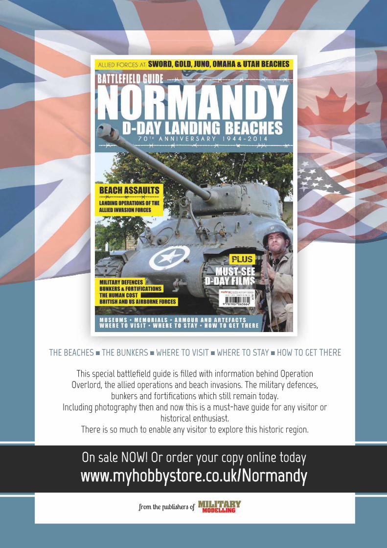
www.myhobbystore.co.uk/Normandywww.myhobbystore.co.uk/NormandyOn sale NOW! Or order your copy online today
from the publishers of
This special battlefi eld guide is fi lled with information behind Operation Overlord, the allied operations and beach invasions. The military defences,
bunkers and fortifi cations which still remain today. Including photography then and now this is a must-have guide for any visitor or
historical enthusiast.There is so much to enable any visitor to explore this historic region.
THE BEACHES ■ THE BUNKERS ■ WHERE TO VISIT ■ WHERE TO STAY ■ HOW TO GET THERE
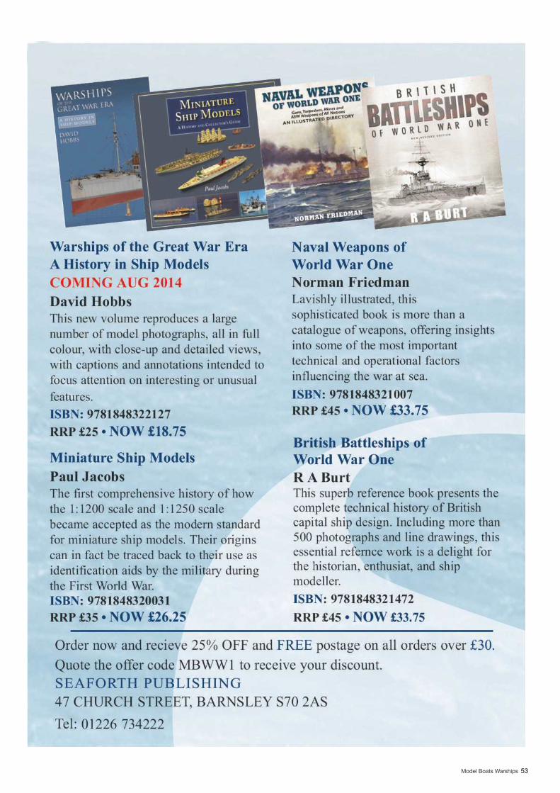
Model Boats Warships 53

2 www.modelboats.co.uk
NEW FOR 2014
humbrol.comFor schools and all youth organisations
Join the Official Airfix Club
D-DAY!
These D-Day gift sets will be available in June to mark the 70th anniversary of D-Day. These four sets illustrate different stages during Operation Overlord and all of these come with vac-form bases to create the perfect diorama.
All the models included in each of these sets are also available to purchase individually.
Official Product
A50
157
D-D
ay A
ir As
sault
A50156 D-Day Sea Assault A50009 D-Day Battlefront
A50162 1:72


![Japan Navy Warship [Art]](https://img.pdfslide.us/doc/110x75/577cd4561a28ab9e78983de0/japan-navy-warship-art.jpg)