Embed Size (px)
Citation preview

1
Model Block Press Sponsor: Geoffrey Wheeler
By
Jordan Brown
Michael Evans
Connor Morrow
Mechanical Engineering Department
California Polytechnic State University
San Luis Obispo
2014

2
Statement of Disclaimer
Since this project is a result of a class assignment, it has been graded and accepted as
fulfillment of the course requirements. Acceptance does not imply technical accuracy or
reliability. Any use of information in this report is done at the risk of the user. These risks may
include catastrophic failure of the device or infringement of patent or copyright laws. California
Polytechnic State University at San Luis Obispo and its staff cannot be held liable for any use or
misuse of the project.

3
Table of Contents Special Thanks ................................................................................................................................. 5
Abstract ........................................................................................................................................... 6
Chapter 1. Introduction .................................................................................................................. 7
Chapter 2. Background Information ............................................................................................... 9
Using the BP9 ............................................................................................................................ 13
Objectives.................................................................................................................................. 17
Chapter 3. Design Development ................................................................................................... 19
Concept Creation ...................................................................................................................... 19
Chapter 4. Description of the Final Design ................................................................................... 28
Overview of the Design ............................................................................................................. 30
Detailed Analysis ....................................................................................................................... 31
Cost Analysis ............................................................................................................................. 32
Material Choices ....................................................................................................................... 37
Safety Considerations ............................................................................................................... 38
Chapter 5. Product Realization ..................................................................................................... 39
Manufacturing .......................................................................................................................... 39
Difference between the Prototype and Final Product ............................................................. 43
Recommendations for Future Manufacturing .......................................................................... 44
Chapter 6. Design Verification Plan .............................................................................................. 45
Chapter 7. Project Management Plan .......................................................................................... 47
Chapter 8. Conclusions and Recommendations ........................................................................... 48
Appendix A: Background Research ............................................................................................... 50
A1. CINVA-Ram Block Press ...................................................................................................... 51
A2. TEK-Block Press ................................................................................................................... 52
A3. Links to Informative Websites ............................................................................................ 53
4
Appendix B: QFD and Decision Matrices ...................................................................................... 54
B1. Original requirements from the sponsor ............................................................................ 54
B2. Quality Function Deployment Matrix ................................................................................. 55
B3. Decision Matrix ................................................................................................................... 57
B4. Pictures of “Swivel” concept design model ........................................................................ 58
Appendix C: Drawing Packet (Assemblies with Bill of Materials, Detailed Part Drawings, Process
and Instrumentation Drawing) ..................................................................................................... 60
Appendix D: List of Vendors, Contact Information and Pricing .................................................... 88
Appendix E: Detailed Supporting Analysis .................................................................................... 89
Tipping Analysis......................................................................................................................... 89
Tipping Analysis cont. ............................................................................................................... 90
Connector Plate Analysis .......................................................................................................... 91
Connector Plate Analysis cont. ................................................................................................. 92
Lever-Ram Fastener .................................................................................................................. 93
Handle Analysis ......................................................................................................................... 94
Rotation-Peg Analysis ............................................................................................................... 95
Rotation-Peg Analysis cont. ...................................................................................................... 96
Rotation-Peg Analysis cont. ...................................................................................................... 97
Appendix F: Gantt Chart ............................................................................................................... 98
Appendix G: Operators Manual .................................................................................................. 100
Operating the BP10 ................................................................................................................. 100
Maintenance ........................................................................................................................... 104
5
Special Thanks Eileen Rossman, for her help as the project advisor.
Geoffrey Wheeler, for giving us an interesting project to work on and having invaluable advice.
Kevin Williams, for performing most of the welds during manufacturing.
Brett Johnson, for performing the welds on the lid of the press.
All the Cal Poly shop techs for their hard work and assistance.
Daniel Jansen, for providing us with various civil engineering tools and places to work.
James Widmann, for loaning us his spring scale for force testing

6
Abstract The Center for Vocational Building Technology came to the Mechanical Engineering department
at Cal Poly, San Luis Obispo with a project to create a new, less expensive model block press
than their current BP9 design. This press would produce ¼ scale model compressed earth
blocks to be sold as souvenirs and used in demonstrations for constructing buildings. After
analyzing the design of the current block presses, JCM came up with the BP10 design. The BP10
operates similarly to the larger block presses, but will cost significantly less to produce and will
have some of the design features enhanced to make it easier to use.

7
Chapter 1. Introduction
The CVBT (Center for Vocational Building Technologies) requests a new working scale model of
their Compressed Earth Block Press which will create ¼ scale compressed earth blocks. The full
size Compressed Earth Block Press uses a mixture of soil and cement to form compressed earth
blocks that are used as building materials. The press is used mainly in rural Thailand, where
many of the working villagers would have to migrate to larger cities to find work during seasons
when they cannot grow food. The press is just one way that the CVBT has been able to keep
those people employed and able to stay with their family during off seasons. In this project, the
main stakeholder is the CVBT, and secondarily, people who buy model block presses for
themselves.
A model block press that creates ⅓ scale blocks, called the BP9, already exists. It creates smaller
compressed earth blocks, used primarily to build model houses or sell as souvenirs. An added
bonus to the block press is that it can be used to demonstrate the process of making earth
blocks.
However, this block press has problems. The cost to make a block press is currently 8500 Baht,
or approximately 250 USD, which is too high. The second problem with the model block press is
the efficiency. Through the different bearings, levers, and during block ejection, a lot of friction
is produced, making it harder to use. Finally, it also has multiple weak points that need to be
reinforced.
Multiple causes result in these problems. One is that the design of the BP9 is extremely similar
to that of the actual block press. By keeping the design so similar, less consideration is made to
how different loads affect the integrity of the press. This would lead to weak points in the
components, making the press harder to use. The high price can be traced back to the materials
and manufacturing process of the model block press. By using materials that are excessive in
strength and designing parts that are more difficult to machine, a lot of money is wasted
producing the block press.
Our goal is to come up with a new model compressed earth block press. This will be done
through the use of 3D modeling, static and dynamic analysis of the working parts, machining

8
and putting together the model, and reiterating this process if something is wrong. While we
have creative reign over this process, the model we will make should resemble and work similar
to how the full sized block press works.
The new model block press will be completed before the end of the calendar year 2014. From
there, the goal is to have a few of these produced to either keep as block-making tools or sell to
the public. This new press will be a much more cost-effective way to produce ¼ scale
compressed earth bricks that are well-suited to build model houses. The new model can also
serve as a demonstration tool for the process of making compressed earth blocks.

9
Chapter 2. Background Information
The compressed earth method for building blocks has been applied in many different places,
and there are multiple solutions available. A little bit of background research shows that people
have been trying to find a cheap, efficient solution to this problem for some time. All of the
block presses that we found, however, have very similar functionalities and forms. All of these
block presses, with pictures, drawings, and detailed specifications can be found in Appendix A.
The sources that provided this information can be found in the References section.
The CINVA-Ram block press was developed by Raul Ramirez at the Inter-American Housing
Center, and is a good example of a standard solution for making compressed earth blocks. It is
made completely out of steel, and compresses a slightly moistened mixture of soil and cement
or soil and lime to make blocks. The CINVA-Ram is able to be transported to make blocks
anywhere. It takes about 2500 blocks from the CINVA-Ram to build a two-room house. Some
benefits to the CINVA-Ram is that the curing process for its blocks does not include baking, and
it is relatively cheap (175 USD, or about 5800 Baht). More specifications are listed in Appendix
A1.
Figure 2-1. The CINVA-Ram Block Press

10
In 1970, the TEK-Block press was developed by the Department of Housing and Planning
Research, Faculty of Architecture at the University of Science and Technology in Kumasi, Ghana.
The goal of this development was to modify the CINVA-Ram to suit local requirements. The end
result is a little bit cheaper than the CINVA-Ram (173 USD, or about 5700 Baht) and there are a
few differences to the design. First of all, the lever arm is a wooden handle that is placed into a
hole for leverage. The reason for this is that it makes the press cheaper, and if there is too
much force being exerted on the machine the lever will be the first thing to break. This makes
for a much less expensive repair, because the press itself does not break. Another difference to
the CINVA-Ram is that the lever is connected to the mould cover, so when the lever comes
away from the press so does the cover. The TEK-Block press is also a stand-alone press; it does
not need to be bolted to the ground for support (TEK- Block Press, Appendix A).
Figure 2-2. The TEK-Block Press
Another block press that pertains to this project is the Fernco MP-612. The MP-612 is portable
and produces blocks that are 6 x 12 x 3.5 inches. It has two six-foot rails that extend out as feet
to help keep the machine from tipping over during operation. The rails, as well as the six-foot
handle, can be detached for easy transport or storage. It also has an optional wheel kit that
makes it easier to move around the job site. The MP-612 costs 2,015 USD (about 66,500 Baht),
so it is relatively expensive (Fernco Metal Products, Appendix A).

11
Figure 2-3. The Fernco MP-612 Block Press
The block press that most directly pertains to this project is the BP9 Mini Block Press. This press
is currently used by the CVBT, and the project is specifically aimed at replacing this press with a
cheaper, more efficient and easy to use machine. The BP9 makes blocks at ⅓ scale of the full
size BP6 press, or 10 x 5 x 3.33 cm, using regular compressed earth block mix. It can make full
and half blocks, and these can be stacked up to make a model home. The BP9 costs 8500 Baht,
or about 258 USD.
Figure 2-4. The BP9 Mini Block Press

12
More information and research on existing block presses can be found in Appendix A.
In December 2012, a Cal Poly student named Nicholas Herskedal completed a thesis on the
strength of compressed earth block walls. In this document there is a section on materials
needed to make compressed earth blocks, and he goes into detail about the process and the
testing of the blocks. The materials he used for compressed earth blocks are soil, sand, and
cement (Herskedal, Appendix 3).
Since our project is for a small-scale model press, there are no existing codes or standards that
need to be met. There were no products or patents out there for a miniature block press, aside
from the one used at the CVBT.

13
Using the BP9
In order to familiarize ourselves with the block creating process and the forces needed to do so,
the team spent a few days using the BP9. One challenge while using the BP9 is that the one on
Cal Poly Campus is missing the bottom plate. This bottom plate creates the female dowels in a
block and also helps completely eject the block. Without the plate, the bottom of the blocks are
not smooth and easily chip away. When pulling the block out, the bottom part sits inside the
compression chamber because it doesn’t have the extra height of the bottom plate to eject it
all the way out. Regardless of this missing piece, creating blocks was still a valuable experience
to learning how the press worked.
Figure 2-5. Michael sifting soil to create a good mixture

14
Figure 2-6. Connor mixing the charge
Figure 2- 7. Some blocks created during this process

15
After creating a few blocks, we decided to analyze how much force was required to compress
the mixture and then how much force was required to eject the block from the housing. A
handheld force-meter was acquired and attached at the handle of the BP9. Data was collected
for two trials. The results can be found in table 2-1. These likely aren’t the most accurate of
data, but they give us a general sense of what is needed to create blocks.
Table 2-1. Forces required for block making
Trial Compression Force (lbf) Ejection Force (lbf)
1 9.5 25
2 9.2 28
Rounded Estimate 10 30

16
Figure 2-7. Finding the force for compressing and ejecting a block

17
Objectives
The primary goal for this project is to have a working model block press by October, 2014. This
block press will meet all of the customer requirements that are detailed in this section in the
formal engineering specification table.
We started our formal design process by putting together a QFD, or House of Quality. This table
which is attached in Appendix B relates the main customers of this project, their requirements,
the specifications of a solution, the competing solutions, and our solution. Requirements are
listed on the left and weighted by importance for each of the customers. Then, in the middle
the specifications are rated by relevance to these requirements, and on the right the competing
products are rated by how they meet these requirements. On the bottom, targets values are
listed for the specifications, and our solution and the competing solutions are rated again on
how they meet those target values. Also on the top of the chart, the specifications are
compared to each other to identify relationships and redundancies. From this chart, we were
able to determine which specifications would be most important for us to focus on.
To meet these requirements, a list of engineering specifications has been made that allows us
to fully test the design of our product. These requirements are organized on Table 2-2 found on
the following page. Under risk, ‘H’, ‘M’, and ‘L’ indicate high, medium, and low risk of achieving
that requirement. Those assigned with higher risk will be harder to attain. The compliance
section is a quick way of identifying what criteria will be used to see if the specification is met.
‘A’ is for analysis, ‘T’ test, and ‘I’ is inspection.

18
Table 2-2. Formal Engineering Specifications
Spec. #
Parameter Description Requirement or
Target Tolerance Risk Compliance
1 Price 1500 baht Max H A
2 Target block density measured with a
penetrometer 5 ksc 0.5 ksc M A, T
3 Time to Produce a Block 30 blocks an hour 5 blocks M T
4 Press Length 10 cm -2 cm + 4 cm
L I
5 Press Width 6 cm -2 cm
+ 4 cm L I
6 Press Height 15 cm ±5 cm L I
7 Maximum Force Applied to the Handle 1.05 kN* ±0.05 kN M A, T
8 Block Length 7.5 cm ±0.05 cm L I
9 Block Width 3.75 cm ±0.05 cm L I
10 Block Height 2.5 cm ±0.05 cm L I
11 Force required to push over (applied at top) 11 N** +2 N L A, T
12 Ability to remain upright during use Yes N/A M A, T
* Weight based on the mass of an average human (70 kg according to Hyper Textbook
http://hypertextbook.com/facts/2003/AlexSchlessingerman.shtml) and using a safety factor of 1.5.
** Force based on 1/10th of max force exerted by an average human during work with just arms (Canadian Center
for Occupational Health and Safety http://www.ccohs.ca/oshanswers/ergonomics/push1.html)

19
Chapter 3. Design Development
Concept Creation
To begin our ideation process, we came up with a list of functions that the press must be able
to perform and maximize in order to be a good design. The three functions that we believe are
at the core of the new model block press are: compression of the charge, ejection of the block,
and reduced friction between parts and the block.
By having these main functions as the focus for our ideation, we began to develop solutions to
them. This was done over the span of about two weeks as we set out to find the idea that
would best meet those criteria. Once we had a significant number of ideas, we created three
Pugh matrices. A Pugh matrix is a way of comparing ideas to see which are the best, while at
the same time providing feedback to see what can be improved in some ideas. The ideas are
matched up against more specific criteria for the press and are assigned either a ‘+’ if the design
meets the criteria better than the existing model, a ‘-’ if the design meets the criteria worse
than the existing model, or an ‘S’ if the design meets the criteria similarly to the existing model.
The Pugh Matrices that were produced are listed on the next page.
There were multiple ideas that we included in the Pugh matrices. The cookie cutter idea would
be a way to compress blocks by have a hinge that held a sheet of metal with the design for the
bock. The sheet would come down onto the block mixture and compress it into blocks. Multiple
blocks could be done at once. The Lobster Shell opener would be a hand held compressed earth
block press. The blocks would be compressed in a device similar to a shell opener. The Stamp
design would be manufactured so that mixture could be put into a housing that looks similar to
a stamp. Then to compress it the operator would push it against a surface.

20
Table 3-1. Concepts for Compressing the Charge
Customer Requirements BP9 Power
Screw Gear & Rack
Cookie
Cutter
Lobster
Shell
Opener The Stamp
Low Cost Datum - - + + -
Compact Datum + S - - +
Builds Blocks Datum S S + S S
Easy to use Datum + + + + -
Similar to Actual Press Datum - - - - -
Makes Different Block Shapes Datum S S S S S
Quickly Makes Blocks Datum - - + S -
Stand Alone Datum + + + + +
Durable Datum - - + + S
Σ+ 0 3 2 6 4 2
Σ– 0 4 4 2 2 4
Σ+/– 0 -1 -2 4 2 -2

21
Table 3-2. Concepts for Ejecting the Block
Customer Requirements BP9 Removable
bottom Sliding shell
Four hinged
walls Sliding door
and press
Low Cost Datum + + S +
Compact Datum – + – S
Easy to use Datum – – + +
Similar to actual press Datum – – – S
Varied block shapes Datum S S S S
Stand alone Datum S + + S
Durable Datum + + – +
Σ+ 0 2 4 2 3
Σ– 0 3 2 3 0
Σ+/– 0 –1 +2 –1 +3

22
Table 3-3. Concepts to Reduce Friction
Customer Requirements BP9 Double-Shell Lowered Peg Non-Rotating
Peg
(Frictionless) Lubrication
Low Cost Datum S S + -
Compact Datum + S + S
Easy to use Datum S + + -
Similar to Actual Press Datum + + - S
Quickly Makes Blocks Datum - S S +
Durable Datum - S S S
Σ+ 0 2 2 3 1
Σ– 0 2 0 1 2
Σ+/– 0 2 4 2 3
Once we had these matrices, the next step was to see which items could be eliminated and
which could be modified. We eliminated the “removable bottom” ejection concept because it
had big problems with friction, which it couldn’t be modified without making it too complicated
or making it similar to another concept. The “sliding shell” concept was eliminated for the same
reason. The “four hinged walls” and “sliding door and press” concepts were both modified.

23
Most of the compression concepts were eliminated. The “gear and rack” and “power screw”
concepts were too complex and expensive, the “cookie cutter” would be too big, the “lobster
shell opener” would be too different from the original, and the “stamp” would be difficult to
add an ejection mechanism to. The original BP9 compression method is used for two of the final
concepts, and a new design was created for the third final concept.
The first idea that we considered is the “BP10.” This will be just a scaled version of the BP9,
which is the current model block press that is being used. There will be minor tweaks to try and
make it more efficient and easier to use, such as lowering the fulcrum pin used to generate
torque to eject the block. The lower it is, the more easily a person can apply a perpendicular
force downward. It would also be revamped to use cheaper materials and less machining time
in order to make it cost less than the BP9 counterpart. With enough small tweaks, it could
theoretically meet all of our specifications.
The second model that we are considering is what we call the “Double-Shell” concept. As
shown in the following sketches, the charge is loaded into an interior compartment with four
hinged walls, and that interior compartment rests inside an exterior shell. After the block is
compressed, the interior part is ejected, and the hinged walls are pulled away to reveal the
block. This eliminates the problem of friction between the completed block and walls during
the ejection process while still maintaining the original shape and look of the original press. A
quick 3D model of it can be seen in Figure 3-1 and 3-2.

24
Figure 3-1. The Double-Shell fully ejected
Figure 3-2. A top down view of the Double-shell when inside the main case

25
The final design that we came up with is the “Swivel”, shown in Figure 3-3. The Swivel is the
most unique design. The design can rotate between two modes; one for loading material, and
one for compressing and ejecting the block. In the loading mode, the sliding door is opened,
and charge is loaded into the box. Then, it is rotated 180° into compression mode. The lid on
top has a lever and is connected to the interior ram by a 4-bar mechanism. The lever is pulled
down to a certain marked point to compress the block, and then the sliding door is opened and
the lever is pulled down all the way to eject the block. We believe that this design is less
complex than the BP9 and has the potential to be inexpensive to produce, and the simple lever
arm motion will make block ejection easier for the user. An example of the swivel can be seen
in Figure 3-3 on the next page. A full set of pictures of the Swivel design are shown in Appendix
D, demonstrating the full process of creating a block with the device.

26
Figure 3-3. The Swivel design in loading mode (left) and compression mode (right)
With these three main concepts, our next objective was to create a decision matrix in order to
see which design succeed the most at satisfying our different requirements. For the criteria, we
used a mix of engineering specifications we have listed in Table 2-2 of the Objectives section
and other customer requirements in order to best encapsulate everything the model should do.
The top portion of the matrix reflects those criteria while the left side lists our models. Each of
the criteria were given a weighting factor that all summed to 1. The concepts were then graded
for each criteria on a scale of 1-10. The product of that grading and the weighting for each
criteria was then summed at the end. The concept with the highest value was the one that
most adequately meets all of our requirements and should be the focus for the project. This
decision matrix can be found in Appendix B.

27
The results of this decision matrix were very close. The design with the highest score was the
Swivel at 6.95, followed closely by the BP10 at 6.725 and the Shell at 6.425. While the Swivel
scored the highest, we still had one more consideration to take into account. This consideration
was time and ability required to fix any malfunctions on the designs we created if they come
up. The BP10 is very similar to the existing model, and therefore if a problem would occur,
there would likely be an available solution. Because the Swivel and Shell are so radically
different, a problem could take weeks to solve. Since all of them scored so similarly, we decided
to pursue the BP10 as our final design choice, as it is nearly tied with the other designs in terms
of the decision matrix, and the design will be easier to fix if any major problems arise in testing.

28
Chapter 4. Description of the Final Design
Figure 4-1. Isometric view of the final BP10 design

29
Figure 4-2. View of the Inside of the BP10.

30
Overview of the Design
The final design that we decided to develop was the BP10. This design is a scaled model of the
BP9 with some choice differences.
The first difference between the BP10 and the BP9 is the placement of the pivot point for
ejection. We have chosen to lower it from its original position in the BP9. This is to help create a
better moment arm for the user when they are ejecting the block.
Another difference made is the sides of the housing. In the BP9 design, there is the charge
housing and then additional parts to create the legs for the press. In our design, we have
decided to make this all out of a 4-walled box. The side of the charge housing extends all the
way to the ground, and contains a slot for the ram-lever fastener to extend into. We feel that
this will require less machining than the previous version and make the assembly easier to
conduct.
One of the biggest changes we made was the addition of feet to the press. One of our design
considerations was to create a block press that would be able to stand on its own during
operation. The BP9 currently has to be bolted down to a surface in order to be used, which
limits where a person can create blocks. The feet that we have added extend the area that the
press sits on. The intended goal is that the feet will create a counter-moment to prevent tipping
caused by the compression or ejection stroke.
As we prepared to prototype the design, a few more changes were made. A small plate was
added to the lid that catches the compression handle at the bottom of its stroke, keeping it
from being pulled too far. The bolts holding the shaped dowels on the lid were flipped back
around to have the heads on top, with the dowels threaded. This was to prevent the bolt heads
sticking out of the bottom of the lid from damaging the block as the lid was opened after
compression. Also, the L-bracket “feet” were changed to be a store-bought component instead
of bent from stock plate metal. Finally, the plate thickness throughout the whole press was
standardized to 3 mm, as opposed to a mix of 3, 5, and 7 mm.

31
Detailed Analysis
The easiest way for the BP10 to fail is when its parts experience excessive shear stress or
bending stresses, which are only induced during operation. Our main objective when
considering the stress on the machine was to make sure that they all had sufficient strength to
withstand our maximum design load, which is 1.05 kN (found in Table 4-1). If the machine is
strong enough to endure more than the full weight of an average human, then it will be ready
for use.
The primary areas of concern were the eccentric fastener, the ram-lever fastener, the rotation
peg, and the ram sides. All the analysis done can be found in Appendix E. For these analyses we
used the design load of 1.05 kN to determine the size of fasteners or if the component could
stand up to the stress. The only problem we encountered was the eccentric fastener. Under the
load of 1.05 kN, the fastener would fail unless it had an absurdly large diameter. So instead, we
continued analysis to see if it could withstand the load that is needed to compress a block in the
BP9. When we did that, the fastener was able to stand up against that load very well. This
means that during compression, we will need to warn the user that excessive weight can break
the fastener.
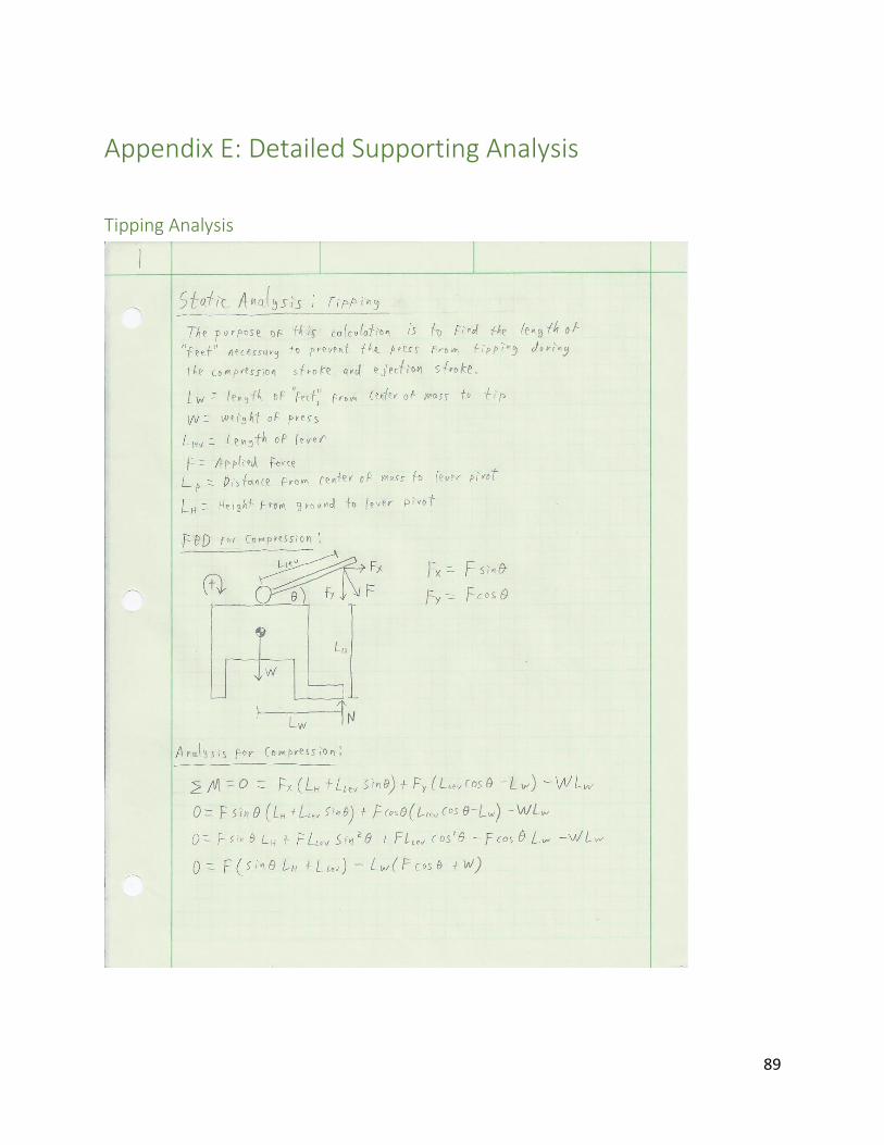
Another part of the analysis was to see at what point the device would tip over during
operation. As seen in the drawings, we had to provide it with stabilizing feet. To calculate the
length of those legs, we did a static analysis of the machine during ejection and compression.
Since more force is applied to the lever during ejection, this is when the machine is most likely
to tip over. The length of the feet was calculated so that they would be long enough to prevent
this from happening.
The calculations for these detailed analysis can be found in Appendix E.
Table 4-1. Safety Factor Table.
Calculation Safety Factor Value Used
Force applied to handle 1.5 1.05 kN

32
Cost Analysis
To begin analyzing the cost of producing a BP10 press, we created a list of parts; some for
manufacture, and some to be bought from vendors. A full list of these parts can be found in
Appendix C, and material pricing can be found in Appendix D. Many of the parts are made of 0.5
cm thick plate metal, some are made of varying diameters of cylindrical stock, and several are
off-the-shelf parts. The following tables show the cost analysis for the parts for a US-based
prototype, both manufactured and off the shelf.

33
Table 4-2. Cost analysis of materials for a single prototype press
Desired Material Amount Vendor
Available
Material Price
0.3 cm HR steel plate 523.675 cm^2 OnlineMetals
12’’x24’' 0.125’’
HR steel plate
$31.06
1.2 cm diameter steel pipe 32 cm
OnlineMetals 24'' 0.5''
diameter HR
pipe
$2.78
0.8 cm diameter steel tube 10.85 cm
OnlineMetals 10’’-12’’
0.3125 OD x
0.049’’ wall
Stainless tube
$4.18
2 cm diameter steel barstock 5.23 cm
OnlineMetals 10''-12'' 0.875''
diameter HR
pipe
$3.77
4 cm diameter steel barstock 2 cm
OnlineMetals 10''-12'' 1.75''
diameter HR
barstock
$15.54
2 cm x 2 cm x 0.3 cm steel angle 102 cm
OnlineMetals 48’’ 0.75’’ x
0.75’’ x 0.125’’
HR steel angle
$4.80
Total $62.13
34
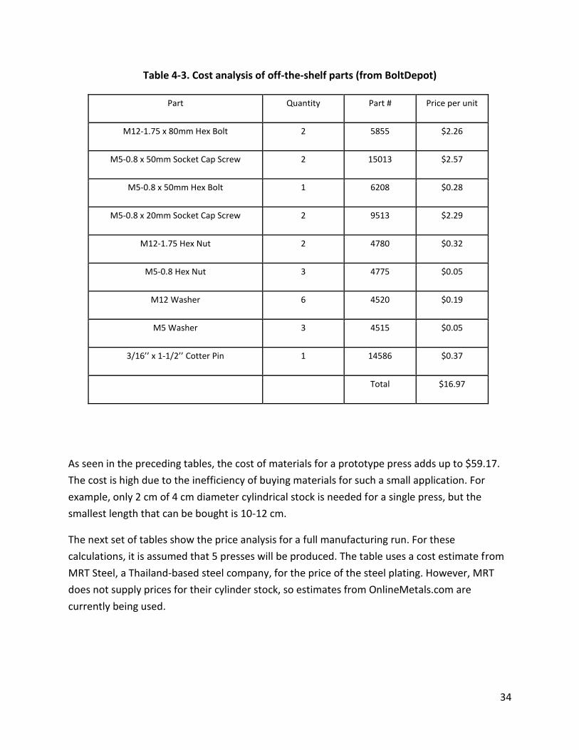
Table 4-3. Cost analysis of off-the-shelf parts (from BoltDepot)
Part Quantity Part # Price per unit
M12-1.75 x 80mm Hex Bolt 2 5855 $2.26
M5-0.8 x 50mm Socket Cap Screw 2 15013 $2.57
M5-0.8 x 50mm Hex Bolt 1 6208 $0.28
M5-0.8 x 20mm Socket Cap Screw 2 9513 $2.29
M12-1.75 Hex Nut 2 4780 $0.32
M5-0.8 Hex Nut 3 4775 $0.05
M12 Washer 6 4520 $0.19
M5 Washer 3 4515 $0.05
3/16’’ x 1-1/2’’ Cotter Pin 1 14586 $0.37
Total $16.97
As seen in the preceding tables, the cost of materials for a prototype press adds up to $59.17.
The cost is high due to the inefficiency of buying materials for such a small application. For
example, only 2 cm of 4 cm diameter cylindrical stock is needed for a single press, but the
smallest length that can be bought is 10-12 cm.
The next set of tables show the price analysis for a full manufacturing run. For these
calculations, it is assumed that 5 presses will be produced. The table uses a cost estimate from
MRT Steel, a Thailand-based steel company, for the price of the steel plating. However, MRT
does not supply prices for their cylinder stock, so estimates from OnlineMetals.com are
currently being used.

35
Table 4-4. Cost analysis of materials for 5 presses
Desired Material Amount Vendor
Available
Material Price
0.3 cm HR steel plate 2618.375 cm^2 MRT Steel
0.3 cm 3' x 6'
HR steel
plate
$40.00
1.2 cm diameter steel barstock 160 cm
OnlineMetals 8' 0.5''
diameter HR
barstock
$8.12
0.8 cm diameter steel tube 54.25 cm
OnlineMetals 24’’ 0.3125
OD x
0.049’’ wall
Stainless
tube
$8.93
2 cm diameter steel barstock 26.15 cm
OnlineMetals 1' 0.875''
diameter HR
barstock
$4.19
4 cm diameter steel barstock 10 cm
OnlineMetals 10''-12''
1.75''
diameter HR
barstock
$15.54
2 cm x 2 cm x 0.3 cm steel angle 510 cm
OnlineMetals 18 ft 0.75’’ x
0.75’’ x
0.125’’ HR
steel angle
$19.90
Total $96.68
36
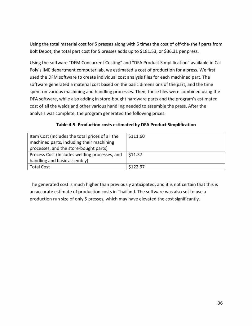
Using the total material cost for 5 presses along with 5 times the cost of off-the-shelf parts from
Bolt Depot, the total part cost for 5 presses adds up to $181.53, or $36.31 per press.
Using the software “DFM Concurrent Costing” and “DFA Product Simplification” available in Cal
Poly’s IME department computer lab, we estimated a cost of production for a press. We first
used the DFM software to create individual cost analysis files for each machined part. The
software generated a material cost based on the basic dimensions of the part, and the time
spent on various machining and handling processes. Then, these files were combined using the
DFA software, while also adding in store-bought hardware parts and the program’s estimated
cost of all the welds and other various handling needed to assemble the press. After the
analysis was complete, the program generated the following prices.
Table 4-5. Production costs estimated by DFA Product Simplification
Item Cost (Includes the total prices of all the machined parts, including their machining processes, and the store-bought parts)
$111.60
Process Cost (Includes welding processes, and handling and basic assembly)
$11.37
Total Cost $122.97
The generated cost is much higher than previously anticipated, and it is not certain that this is
an accurate estimate of production costs in Thailand. The software was also set to use a
production run size of only 5 presses, which may have elevated the cost significantly.

37
Material Choices
The BP10 is comprised exclusively of low-carbon steel. The steel will comprise everything
except for the screws and nuts. The reason for choosing low-carbon steel is because it is fairly
inexpensive and easily accessible in Thailand, but still has high enough strength for this
application, as seen in the stress analysis in Appendix F.

38
Safety Considerations
In order to make the machine safe for use, many of the corners in the metal have been rounded
to prevent lacerations from handling the BP10.
Most of the BP10 parts are designed to withstand a load caused by 1.05 kN applied to the lever,
although it is not advised to apply this much force. The one part that does not meet this design
criteria is the eccentric bolt, but this part still has a high safety factor compared to how much
force is needed to operate the press.

39
Chapter 5. Product Realization Manufacturing
With our final design finished and parts in our possession, we began the task of manufacturing
a BP10. For the prototype we decided to machine all of the custom parts ourselves and have
other people handle the welding. A summary table of how parts were machined are listed in
Table 5-1.
The first thing we did was cut out most of the parts out of the sheet of steel that we had. A
plasma cutter was used to do the cutting. The plasma cutter we used had options for automatic
jogging, or cutting in a straight line along the given direction. This allowed us to cut in
reasonably straight lines, which was beneficial as most of the parts are rectangular in shape.
The one object that would require a lot of working was the eccentric receiver, as it has a curved
edge that needs to be very close to tolerance. To machine that part we first cut it out in a
triangle and then worked in the curve using a hand held grinder.
With most of the rough cuts done, we then worked on making the edges within tolerance and
smooth. A grinding wheel was used to get rid of the melted steel and then all of the edges were
milled to the given dimension.
Figure 5-1. Milling One of the Pieces
40
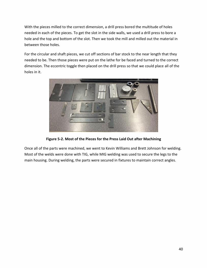
With the pieces milled to the correct dimension, a drill press bored the multitude of holes
needed in each of the pieces. To get the slot in the side walls, we used a drill press to bore a
hole and the top and bottom of the slot. Then we took the mill and milled out the material in
between those holes.
For the circular and shaft pieces, we cut off sections of bar stock to the near length that they
needed to be. Then those pieces were put on the lathe for be faced and turned to the correct
dimension. The eccentric toggle then placed on the drill press so that we could place all of the
holes in it.
Figure 5-2. Most of the Pieces for the Press Laid Out after Machining
Once all of the parts were machined, we went to Kevin Williams and Brett Johnson for welding.
Most of the welds were done with TIG, while MIG welding was used to secure the legs to the
main housing. During welding, the parts were secured in fixtures to maintain correct angles.

41
Figure 5-3. Parts in Fixtures to be Welded
After all of the parts were welded correctly, the prototype was assembled. The assembly is
quick and easy. Bolts are placed through their given holes, with washers and nuts to keep them
in place. The primary handle is secured in the eccentric toggle with a cotter pin.
Figure 5-4. Assembling the BP10 and the Finish Prototype

42
Table 5-1
Part Manufacturing Processes
All main housing pieces Plasma cutting, milling, grinder
Rectangular lever pieces Plasma cutting, milling, grinder
Eccentric Band saw, lathe, center drill
Eccentric receiver Plasma cutting, milling, hand grinder
Male Dowels Band saw, lathe, center drill, tap, hand grinder
Various cylindrical parts Band saw, milling
Support legs Band saw
43
Difference between the Prototype and Final Product
There are few differences between the prototype and the final product. While the team was
making the BP10, the machines we were working with were all based in the English system of
measurement. Because of this, we used drill bits and bolts that most closely matched the
metric measurements. This did not result in an issue with the dimensions, and the prototype
still reflects what is on the drawings.
44
Recommendations for Future Manufacturing
In order to make manufacturing go more smooth, there a few things that could be done before
hand. One of the most complicated parts to machine is the toggle rest. In order to get the
correct dimensions for it, a lot of time has to be spent hand grinding the metal. We can improve
the speed of this step by using a guided plasma cutter. During our manufacturing, the available
plasma cutter had the option to trace along lines in order to cut a desired shape. However, it
was not working when we went to use it. We believe it would be a very useful machine to have
during manufacturing, especially when doing a production run of multiple BP10’s.
Another way to make manufacturing more efficient would be to create welding fixtures that
place the parts in the proper angles. During prototyping, we did not create a fixture for the
parts, but did use many clamps to get the parts into place. Making multiple BP10’s would
benefit from having dedicated fixtures to allow the welding to go much more quickly.

45
Chapter 6. Design Verification Plan
With the BP10, there are three major things that were tested for. These are the price to
produce one, the quality of the blocks created, and how well it handles different stresses. For a
summary of the results, the full design verification plan can be found in Appendix H.
The cost to produce one of the BP10’s was calculated by using determining how much the
materials cost and then finding out how much the different machining and welding processes
would cost. We found our materials cost about 80 USD. However, this is for making one press.
It is higher than what we wanted it to be, but if this were a production run of multiple BP10’s
the material cost would decrease because we bought a lot of excess material for the prototype.
The total cost estimated by the DFA software including its own estimate of material cost for a
run of 5 presses was approximately $120. This is also higher than we anticipated, but it’s hard
to tell if the software’s estimate is accurate for such a small scale production.
Testing the quality of the blocks required us to finish the prototype and come up with a mixture
that we found suitable for the blocks. We settled on a mixture that was comprised of 90% soil
and 10% cement. We found that this created solid blocks that cured well. With the mixture
decided upon, we began making blocks. During testing, we produced 100 blocks to see if the
blocks themselves were of usable quality and if the machine would operate reliably. The BP10
worked fine during the production run. It needed to be cleaned out a few times with water.
After rinsing it with water, a few parts slightly rusted. This could be prevented if we had painted
the parts with a protective coat. Our solution to the rust was just to use an oil lubricant to make
the parts slide easily once again. Once lubricated, it operated fine and was able to make the
blocks.
The blocks themselves met our specifications, but had one defect. The blocks made had a slight
angle that caused one end of the block to be slightly above the other side. Upon further
inspection of the press, we determined that this was a defect formed due to our manufacturing
job. Because of the position of the slot in the main walls relative to the chamber, the
compression ram sits just slightly crooked. If a more experienced machinist had made the
prototype, we are confident that this defect wouldn’t be present.
Originally we had planned to conduct fatigue testing on the machine. However, we lacked the
proper set up to test the BP10 in this way. In order to do this, the team would have had to
46
create a fixture to attach to an actuator and then let it run multiple cycles for both the
compression and ejection motions. Instead of performing this test, we decided that making 100
blocks would give us sufficient information if the BP10 could handle the normal stresses of use.
As mentioned previously, the only trouble came with rust and dirt causing friction between the
parts, which can be remedied with regular cleaning and application of a lubricant like WD-40.
Aside from that, the BP10 was able to withstand the normal forces that it would experience.
We decided against seeing what the maximum force it could withstand, as the destructive
testing would mean we would need to make multiple prototypes. With the factor of safety that
we included in our design calculations, we are confident that it will not break unless put under
extreme loading conditions, which would be a force that is more than the weight of an average
person.
47
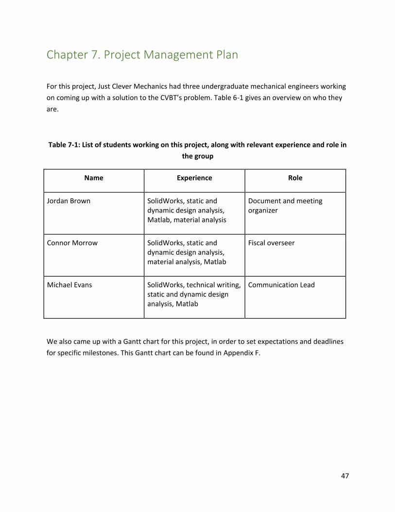
Chapter 7. Project Management Plan
For this project, Just Clever Mechanics had three undergraduate mechanical engineers working
on coming up with a solution to the CVBT’s problem. Table 6-1 gives an overview on who they
are.
Table 7-1: List of students working on this project, along with relevant experience and role in
the group
Name Experience Role
Jordan Brown SolidWorks, static and dynamic design analysis, Matlab, material analysis
Document and meeting organizer
Connor Morrow SolidWorks, static and dynamic design analysis, material analysis, Matlab
Fiscal overseer
Michael Evans SolidWorks, technical writing, static and dynamic design analysis, Matlab
Communication Lead
We also came up with a Gantt chart for this project, in order to set expectations and deadlines
for specific milestones. This Gantt chart can be found in Appendix F.

48
Chapter 8. Conclusions and Recommendations
This project progressed very well. As a team we are pleased with how our final product turned
out. There were a few hiccups and difficult goals to accomplish, but overall they were handled
well. We believe we have met all of the expectations of the project to some degree.
Making a block press that produced scale models was the easiest expectation to meet, as it
meant just reducing the size of any chamber to match the design lengths for the correct size
blocks.
The second easiest obstacle to overcome was solving the problem of the machine tipping over.
Many ideas were thought of on how to solve this, but when we needed to implement a final
decision, the addition of feet was the simplest idea. It adds little to the cost of materials. The
only downside to the feet is that it makes the machine much longer. This could possibly
interfere with storage and makes it so that the BP10 can only be used in a space that allows for
the entire length of the feet. However, this is preferable to having to find an area to bolt it
down, like the BP9 needs.
One goal we had difficulty with was the cost to produce the machine. Originally we wanted to
make it cost around 45 dollars. We planned on doing that by ordering materials in bulk and
cutting down on machining processes. While that was still the goal, after ordering our initial
parts, we realized that making it $45 was going to be impossible. The parts alone cost around
$30, so that would mean that the machining would have to be less than $10 to produce. That is
an impossible goal. However, if all of the machining is done by the CVBT, then that cost can
certainly go down. Based off our estimates, however, the machining will cost around $100.
This informs the most difficult aspect of this project: the machining. No one on the team was
adept at machining, but all had some experience. Because we did have some knowledge of
machining processes, we decided to tackle it ourselves, and have someone else do the welding
for us. However, machining proved to be much more difficult than expected, and delayed us by
several weeks. Working with mild carbon steel was much more difficult than working with
aluminum, which is what we had experience in. However, we were able to finish all of the
machining, albeit with tolerances that were a little off. We still believe that the way we
designed the product will be easy for an experienced machinist to pull off, but for us it was a
challenge.

49
Appendices

50
Appendix A: Background Research
This appendix contains a majority of the background research that was done before initial
concepts were created for this project. Most of the information revolves around the different
types of compressed earth block presses. Some of them heavily influenced our design choices.
51
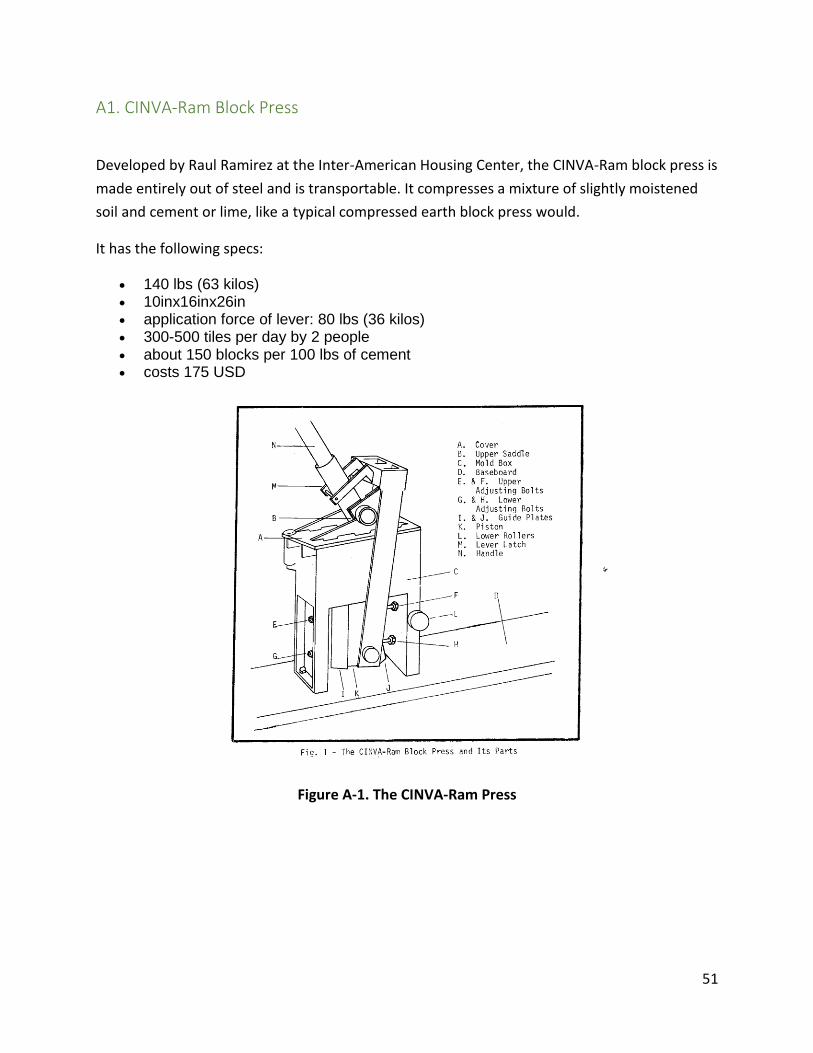
A1. CINVA-Ram Block Press
Developed by Raul Ramirez at the Inter-American Housing Center, the CINVA-Ram block press is
made entirely out of steel and is transportable. It compresses a mixture of slightly moistened
soil and cement or lime, like a typical compressed earth block press would.
It has the following specs:
140 lbs (63 kilos) 10inx16inx26in application force of lever: 80 lbs (36 kilos) 300-500 tiles per day by 2 people about 150 blocks per 100 lbs of cement costs 175 USD
Figure A-1. The CINVA-Ram Press

52
A2. TEK-Block Press
The TEK Block press was developed in 1970 by the Department of Housing and Planning
Research. The goal was to modify the CINVA-Ram to suit local requirements. The lever arm is
made out of wood which serves a dual purpose. The first is to make the press cheaper. It also
serves as a fail-safe; if too much force is applied, the lever will break before any damage is done
to the machine.
The TEK-Block Press has the following specs:
Size of Machine: 32 x 23 x 79 cm Weight of Machine: 85 kg Standard Block Size: 29 x 21.5 x 14 cm Price: $173 USD Output Rate: 50 blocks per hour
Figure A-2. The TEK-Block Press

53
A3. Links to Informative Websites
The following links will lead to websites with details on block presses or compressed earth
blocks themselves.
1. CINVA-Ram Block Press
http://www.cd3wd.com/cd3wd_40/vita/cinvaram/en/cinvaram.htm
accessed 1/23/14
2. TEK-Block Press
http://collections.infocollections.org/ukedu/uk/d/Jh2380e/6.7.4.html#Jh2380e.6.7.4
accessed 1/23/14
3. Video of Ceta Ram Block Press During Compression and Ejection
http://www.youtube.com/watch?v=R_3xGySdfNg&list=PLEU-
v0sCVSix_rBtMVOx_a6Ird2CpVAV_
accessed1/22/14
4. Fernco MP-612
http://www.ferncometal.com/products.htm
accessed 1/23/14
5. Soeng Thai Interlocking Compressed Earth Block Press Model BP6
http://cvbt-web.org/?q=Equipment
http://www.cvbt-web.org/uploads/Equip/Ad-BP5e3.pdf
accessed: 1/23/14
6. Interlocking Compressed Earth Block (ICEB)
http://digitalcommons.calpoly.edu/cgi/viewcontent.cgi?article=1965&context=theses
accessed 1/23/14
7. BP9 Mini Block Press
http://cvbt-web.org/?q=BP9-MINI-BLOCK-PRESS
accessed: 1/23/14

54
Appendix B: QFD and Decision Matrices
B1. Original requirements from the sponsor ● The production cost of the press should be under 1500 baht
● The press should produce blocks that are 7.5 x 3.75 x 2.5 cm
● The press should be free-standing
● Modes for half-size and full-size blocks
● Green color

55
B2. Quality Function Deployment Matrix
The QFD on the next page expands on the original requirements from the sponsor and includes
possible requirements of secondary customers. Based on the requirements, we came up with
technical specifications that can be measured to test how the product meets the customer
needs.

56
Figure B1: Quality Function Deployment (QFD) matrix for the block press

57
B3. Decision Matrix
Figure B1: Decision matrix for three block press concept

58
B4. Pictures of “Swivel” concept design model
Figure B1: The Swivel concept design in loading mode (top two), transitioning to compression
mode (bottom left) and in compression mode (bottom right)

59
Figure B2: The Swivel concept design in the process of compression (left) and ejecting a
completed block (right)

60
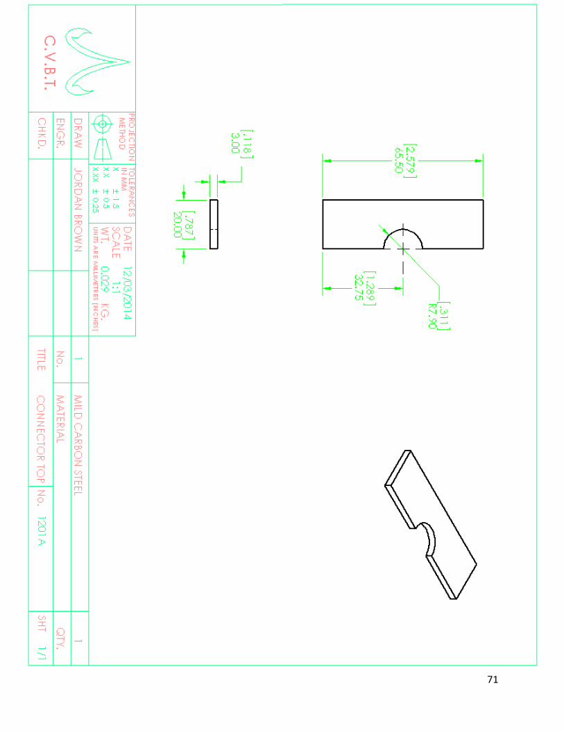
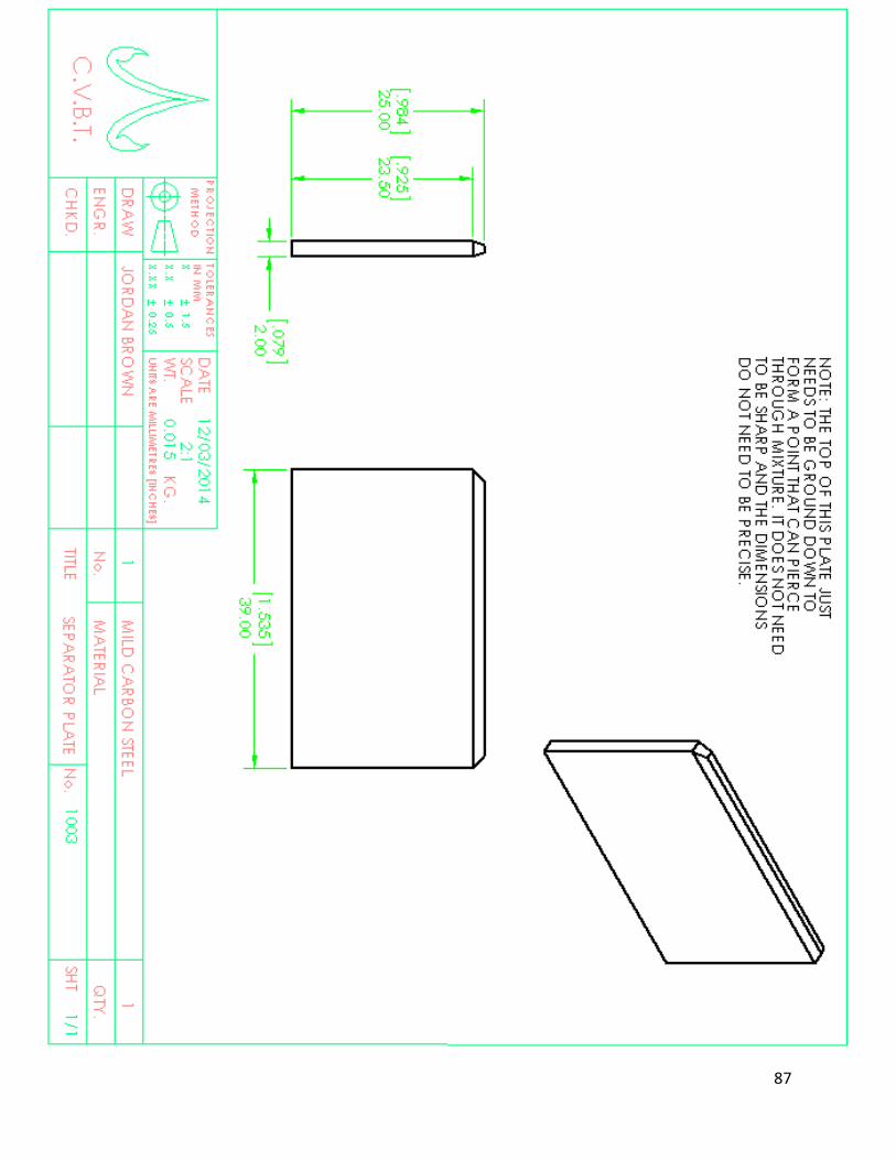
Appendix C: Drawing Packet (Assemblies with Bill of Materials, Detailed Part Drawings, Process and Instrumentation Drawing)

61

62

63

64

65

66

67
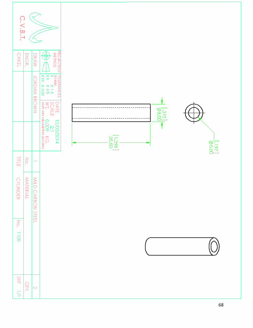
68

69

70
71

72

73

74

75

76

77

78

79

80

81

82

83

84

85

86
87

88
Appendix D: List of Vendors, Contact Information and Pricing
Vendor Country Phone Email
OnlineMetals US 206-285-8603 [email protected]
Bolt Depot US 1-866-337-9888 [email protected]
MRT Steel Thailand +(66) 2897-2610-5 [email protected]
89
Appendix E: Detailed Supporting Analysis
Tipping Analysis

90
Tipping Analysis cont.

91
Connector Plate Analysis

92
Connector Plate Analysis cont.

93
Lever-Ram Fastener

94
Handle Analysis

95
Rotation-Peg Analysis

96
Rotation-Peg Analysis cont.

97
Rotation-Peg Analysis cont.

98
Appendix F: Gantt Chart
Figure F1: Gantt chart for the First Quarter
Figure F2: Gantt Chart for the Second Quarter

99
Figure F3: Gantt Chart for the Third Quarter
Figure F6: Gantt Chart Legend

100
Appendix G: Operators Manual
Operating the BP10 The BP10’s operation follows the same 7-part process as the BP9. The steps are:
1. Load the mixture into the main housing. The mixture found to be best for the BP10 was 90%
soil, 10% cement, and enough water content to make the mixture break into several clumps in
a drop test. The amount of mixture used for one block is approximately 125 g. Fill the chamber
to the brim with the mixture and press it down manually with fingers, then add the rest of the
mixture.
Figure G1. Initial Loading Position

101
2. Making sure the tops of the cylinders and the edges of the lid and walls are clear of mixture,
close the lid and move the lever-assembly into position.
Figure G2. Closing the Lid and Moving the Lever Assembly into Position
3. Pull down on the sub-lever until it is fully horizontal and touching the lever stop.
Figure G3. Compressing the Contents

102
4. Move the lever-assembly back into its original position, and open the lid.
Figure G4. Returning the Assembly to its original position
5. Push down on the lever-assembly to eject the block.
Figure G5. Ejecting the Block
103
6. Remove the compressed earth block from the chamber. It is likely that the press plate will
stick to the block after ejecting. To remove the press plate from the block, pinch the sides
between your thumb and fingers, and gently pull it off with a rocking motion.
7. Return the lid and lever-assembly into its original position.

104
Maintenance The biggest issue with the BP10 is that it will often get the soil mixture stuck in between moving
surfaces. This creates added friction and makes block ejection difficult. In order to combat this,
the machine should be washed with water about every 25-50 blocks.
Another thing to keep in mind is that when it starts binding up, lubrication should be applied
liberally to surfaces that move and rotating parts. If it is not lubricated and is difficult to use, the
excess force could damage the parts.

105
Appendix H: DVP&R