Embed Size (px)
Citation preview
Model-BasedSystems Engineering
on aQuick Reaction Program
20 May 2015
Charles H. PattonEngineering Manager and Systems Engineer
Copyright 2015 Northrop Grumman Systems Corporation. All rights reserved.
2
Agenda
• Why invoke Model-Based Systems Engineering?
• What is Model-Based Systems Engineering?
• What we did on the Surrogate SATCOM IRaD
• What should you do?
Copyright 2015 Northrop Grumman Systems Corporation. All rights reserved. Approved for Public Release #15-0852; Unlimited Distribution
3
The Perception?
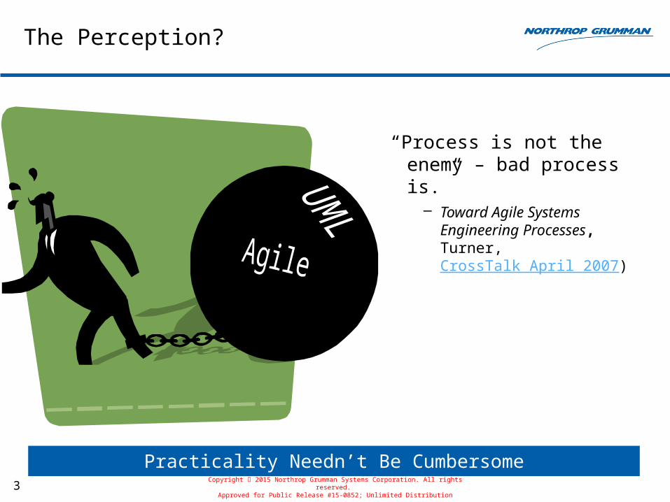
“Process is not the enemy – bad process is.”
– Toward Agile Systems Engineering Processes, Turner, CrossTalk April 2007)
Practicality Needn’t Be CumbersomeCopyright 2015 Northrop Grumman Systems Corporation. All rights reserved.
Approved for Public Release #15-0852; Unlimited Distribution
4
Why
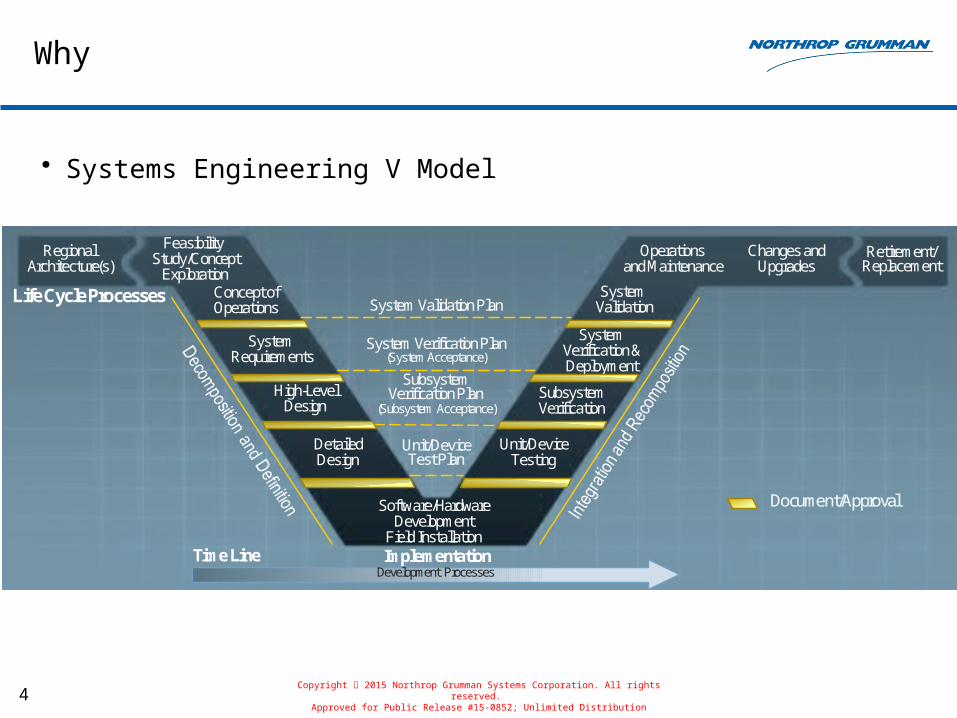
• Systems Engineering V Model
System Validation Plan
RegionalArchitecture(s)
Feasibility Study/Concept
ExplorationConcept ofOperations
SystemRequirements
High-LevelDesign
DetailedDesign
Software/HardwareDevelopment
Field Installation
Operationsand Maintenance
SystemValidation
SystemVerification &Deployment
SubsystemVerification
Unit/DeviceTesting
Changes andUpgrades
Retirement/Replacement
System Verification Plan(System Acceptance)
SubsystemVerification Plan
(Subsystem Acceptance)
Unit/DeviceTest Plan
Life Cycle Processes
ImplementationDevelopment Processes
Time Line
Document/Approval
Copyright 2015 Northrop Grumman Systems Corporation. All rights reserved. Approved for Public Release #15-0852; Unlimited Distribution
5
Why (cont.)
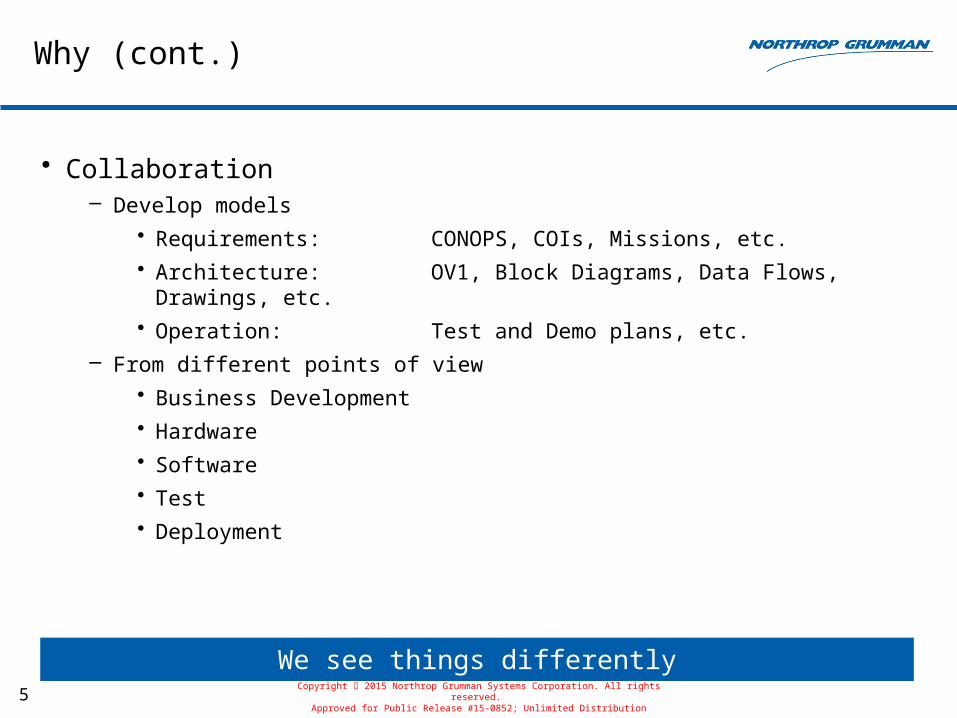
• Collaboration– Develop models
• Requirements: CONOPS, COIs, Missions, etc.
• Architecture: OV1, Block Diagrams, Data Flows, Drawings, etc.
• Operation: Test and Demo plans, etc.
– From different points of view
• Business Development
• Hardware
• Software
• Test
• Deployment
We see things differentlyCopyright 2015 Northrop Grumman Systems Corporation. All rights reserved.
Approved for Public Release #15-0852; Unlimited Distribution
6
Why (cont.)
• Coordination– Multiple engineering efforts
– Accommodate changes
• Communication– Common understanding
• What the system is supposed to do
• How the system is configured
– Define subsystems and components
– Identify interfaces
– Logical and Physical
Effective Development is the GoalCopyright 2015 Northrop Grumman Systems Corporation. All rights reserved.
Approved for Public Release #15-0852; Unlimited Distribution
7
What
• Model-based systems engineering (MBSE) is the formalized application of modeling to support system requirements, design, analysis, verification and validation activities beginning in the conceptual design phase and continuing throughout development and later life cycle phases
• A model is an approximation, representation, or idealization of selected aspects of the structure, behavior, operation, or other characteristics of a real-world process, concept, or system, i.e. an abstraction
• A model usually offers different views in order to serve different purposes
– A view is a representation of a system from the perspective of related concerns or issues
Copyright 2015 Northrop Grumman Systems Corporation. All rights reserved. Approved for Public Release #15-0852; Unlimited Distribution
8
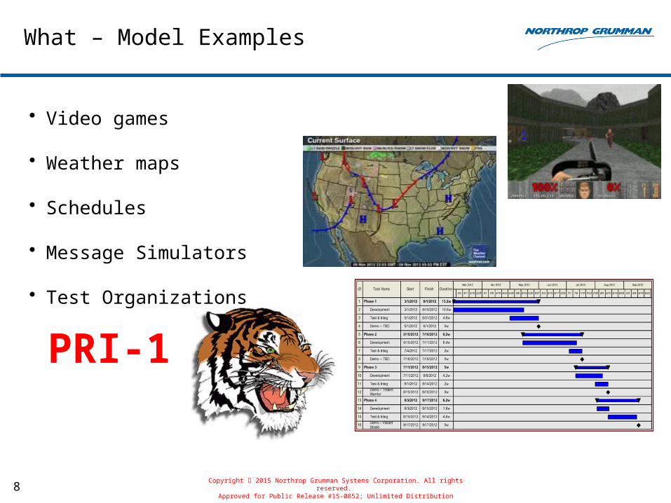
What – Model Examples
• Video games
• Weather maps
• Schedules
• Message Simulators
• Test Organizations
PRI-1
Copyright 2015 Northrop Grumman Systems Corporation. All rights reserved. Approved for Public Release #15-0852; Unlimited Distribution
9
What – View Examples
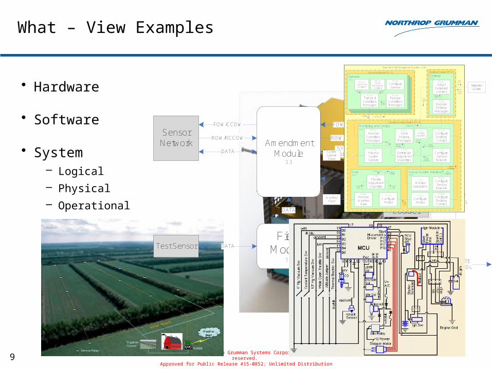
• Hardware
• Software
• System– Logical
– Physical
– Operational
Copyright 2015 Northrop Grumman Systems Corporation. All rights reserved. Approved for Public Release #15-0852; Unlimited Distribution
Amendment Module
1.1
Config Loader
SYSTEMCONFIG
Control Module
1.2
FOW/CCOW
DATA
Sensor Network
ROW/RCCOW
FOW/CCOW
ROW/RCCOW
SYSTEMCONTROL
DATATest SensorRemote Control
REMOTECONTROL
Field Module
1.3REMOTE
CONTROL
DATA
SYSTEMCONFIG
REMOTECONTROL
Remote Soil Management System (1.0)
Delivery Station (P1.3)Sensor Network (P1.1)
Central Control Station (P1.2)
SensorsA1.1
Monitoring and ControlA1.2
DeliveryA1.3
Human-System InterfaceA1.5
DataA1.4
Weather Feed
Irrigation System
F1.3.1
Adjust Delivered Content
F1.3.2
Receive Delivery
Messages
F1.2.1
Receive Conditions Messages
F1.2.3
Determine Adjustment Quantities
F1.2.2
Send Delivery
Messages
F1.2.5
Configure Sensor Network
F1.2.4
Configure Delivery Control
F1.1.1Sense Soil Conditions
F1.1.3
Transmit Conditions Messages
F1.1.4
Receive Conditions Messages
F1.4.2
Receive Weather
Data
F1.4.3
Configure Model
F1.4.1
Provide Adjustment Quantities
F1.5.2
Configure Sensor Network
F1.5.4
Configure Delivery Control
F1.5.1
Monitor Operations
F1.5.3
Configure Model
F1.1.5
Configure Sensor
System Update Feed
F1.2.6
Process System Update
Fault Signal
Valve Cmd
Conditions
Conditions
Conditions
Conditions
Delivery Cmd
Delivery Cmd
Adjustment Quantities
Delivery Configuration
Sensor Configuration
Sensor Configuration
Delivery Configuration
F1.2.7
Monitor Operations
Fault Signal
Ops Data
Model Data
Model Data
Weather Data
Adjustment Quantities
Conditions
Fault Signal
F1.1.2Sense
Atmospheric Conditions
Conditions
10
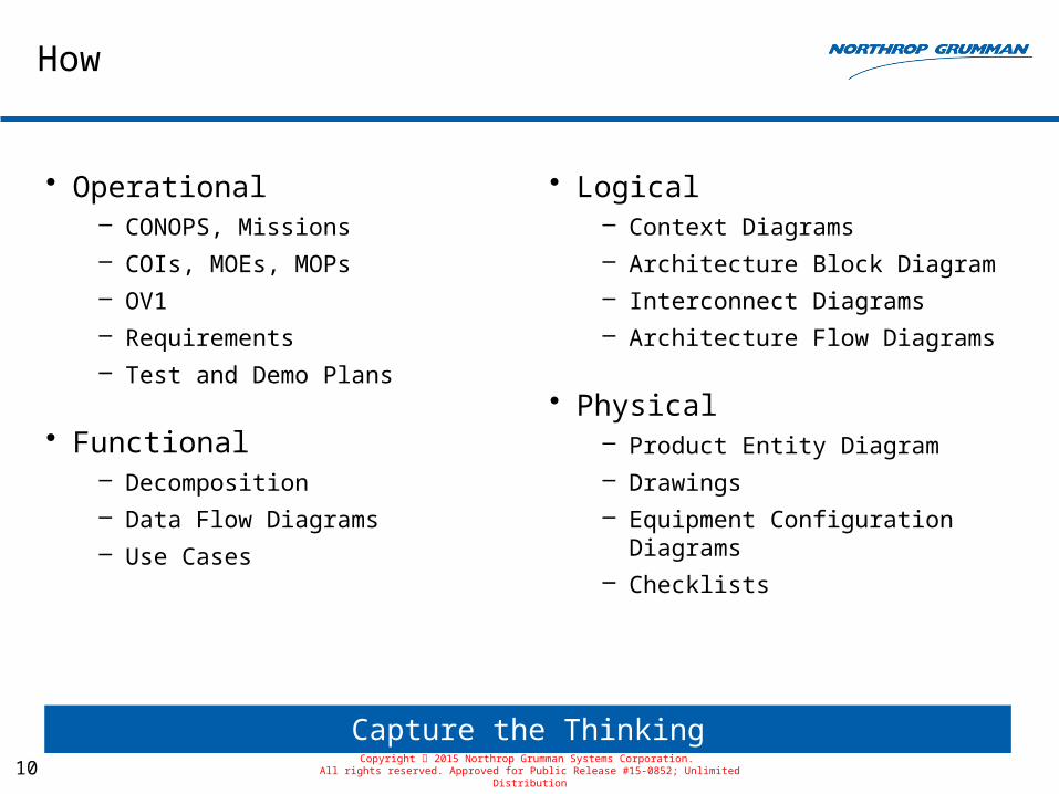
How
• Operational– CONOPS, Missions
– COIs, MOEs, MOPs
– OV1
– Requirements
– Test and Demo Plans
• Functional– Decomposition
– Data Flow Diagrams
– Use Cases
• Logical– Context Diagrams
– Architecture Block Diagram
– Interconnect Diagrams
– Architecture Flow Diagrams
• Physical– Product Entity Diagram
– Drawings
– Equipment Configuration Diagrams
– Checklists
Capture the ThinkingCopyright 2015 Northrop Grumman Systems Corporation.
All rights reserved. Approved for Public Release #15-0852; Unlimited Distribution
11
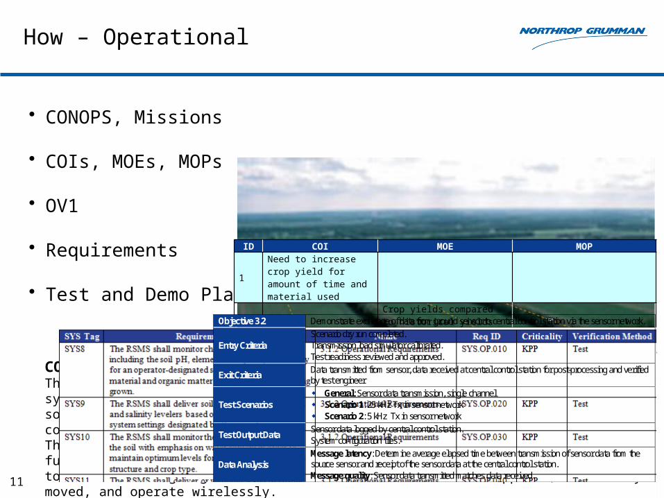
How – Operational
• CONOPS, Missions
• COIs, MOEs, MOPs
• OV1
• Requirements
• Test and Demo Plans
ID COI MOE MOP
1Need to increase crop yield for amount of time and material used
1.1 Crop yields compared to historical yields under similar conditions
1.1.1 Annual crop yield1.1.2 Cost of soil amendments1.1.3 Time (hours) to manage irrigation
2Need to minimize change impact on the host irrigation system
2.1 Percentage change in operability2.1.1 Percentage change to physical
interfaces2.1.2 Percentage change to user interfaces2.1.3 Percentage change to user instructions2.2 Percentage change in componentry2.2.1 Number of new parts
2.2.2 Number of replaced parts
2.2.3 Number of discarded part
Copyright 2015 Northrop Grumman Systems Corporation. All rights reserved. Approved for Public Release #15-0852; Unlimited Distribution
CONCEPT FOR THE PROPOSED SYSTEMThe RSMS is a hardware and software solution applied to an existing irrigation system to monitor soil conditions and control the application of water-based soil amendments according to a tailorable parametric model. The RSMS can be configured to accommodate present and short-term forecast weather conditions. The human-system interface (HSI) provides access to the monitoring and control functions, and allows the user to tailor the parameters of the heuristic model to best suit on-going local conditions. Sensors are hot-swappable, are easily moved, and operate wirelessly.
Objective 3.2 Demonstrate exchange of data from ground sensor to central control station via the sensor network.
Entry Criteria Scenario dry run completed. Transmission load simulator calibrated. Test readiness reviewed and approved.
Exit Criteria Data transmitted from sensor, data received at central control station for post-processing and verified by test engineer
Test Scenarios General: Sensor data transmission, single channel Scenario 1: 25 kHz Tx in sensor network Scenario 2: 5 kHz Tx in sensor network
Test Output Data Sensor data logged by central control station. System configuration files.
Data Analysis Message latency: Determine average elapsed time between transmission of sensor data from the source sensor and receipt of the sensor data at the central control station. Message quality: Sensor data transmitted matches data received.
12
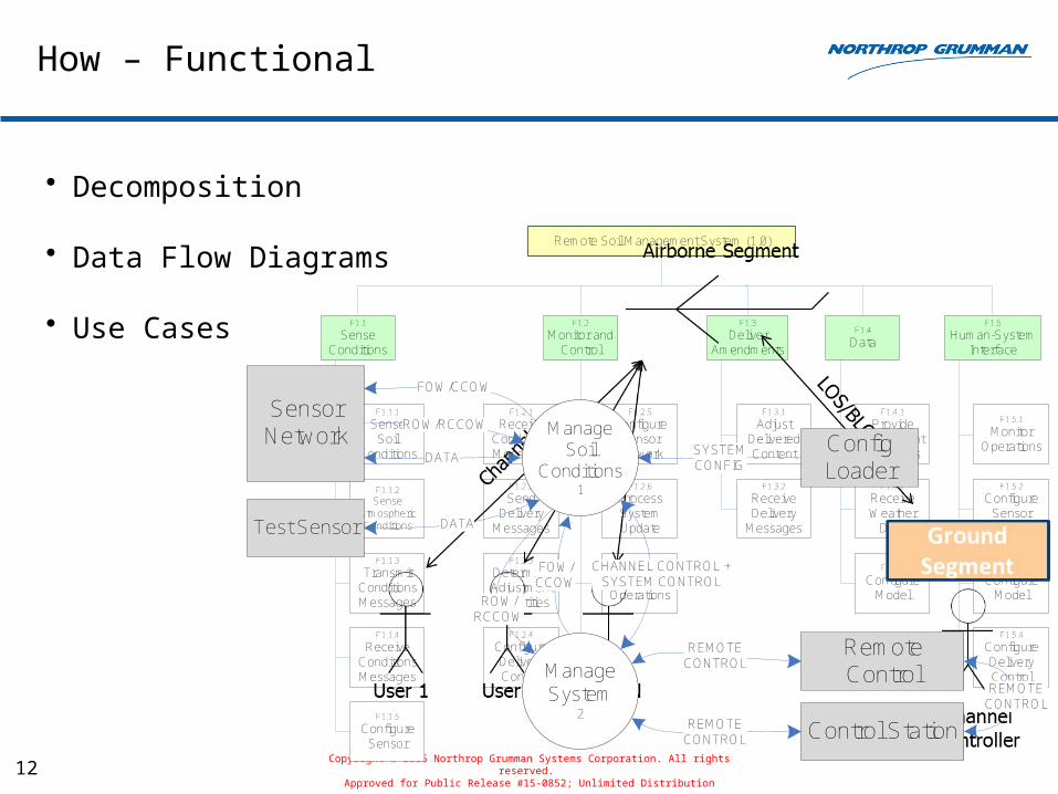
How – Functional
• Decomposition
• Data Flow Diagrams
• Use Cases
Copyright 2015 Northrop Grumman Systems Corporation. All rights reserved. Approved for Public Release #15-0852; Unlimited Distribution
Remote Soil Management System (1.0)
F1.1
Sense Conditions
F1.2
Monitor and Control
F1.3
Deliver Amendments
F1.5
Human-System Interface
F1.4
Data
F1.3.1
Adjust Delivered Content
F1.3.2
Receive Delivery
Messages
F1.2.1
Receive Conditions Messages
F1.2.3
Determine Adjustment Quantities
F1.2.2
Send Delivery
Messages
F1.2.5
Configure Sensor Network
F1.2.4
Configure Delivery Control
F1.1.1
SenseSoil
Conditions
F1.1.3
Transmit Conditions Messages
F1.1.4
Receive Conditions Messages
F1.4.2
Receive Weather
Data
F1.4.3
Configure Model
F1.4.1
Provide Adjustment Quantities
F1.5.2
Configure Sensor Network
F1.5.4
Configure Delivery Control
F1.5.1
Monitor Operations
F1.5.3
Configure Model
F1.1.5
Configure Sensor
F1.2.6
Process System Update
F1.2.7
Monitor Operations
F1.1.2
SenseAtmospheric Conditions
Manage Soil
Conditions1
Manage System
2
CHANNEL CONTROL +SYSTEM CONTROL
DATA
Sensor Network
FOW/CCOW
ROW/RCCOW
DATA
Config Loader
SYSTEMCONFIG
Test Sensor
RemoteControl
Control Station
REMOTECONTROL
REMOTECONTROL
REMOTECONTROL
FOW/CCOW
ROW/RCCOW
13
ETHERNETRADIOFREQUENCY
RADIOFREQUENCY
CL-510
CL-510
ETHERNET
ETHERNET
ETHERNET
RADIOFREQUENCY
Amendment Module
1.1
Config Loader
Control Module
1.2
Sensor Network
Test SensorRemote Control
Field Module
1.3
Amendment Module
1.1
Config Loader
SYSTEMCONFIG
Control Module
1.2
FOW/CCOW
DATA
Sensor Network
ROW/RCCOW
FOW/CCOW
ROW/RCCOW
SYSTEMCONTROL
DATATest SensorRemote Control
REMOTECONTROL
Field Module
1.3REMOTE
CONTROL
DATA
SYSTEMCONFIG
REMOTECONTROL
RSMS0
Config Loader
SYSTEMCONFIG
DATA
Sensor Network
FOW/CCOW
ROW/RCCOW
Test Sensor DATA
RemoteControl
Control Station
REMOTECONTROL
REMOTECONTROL
REMOTECONTROL
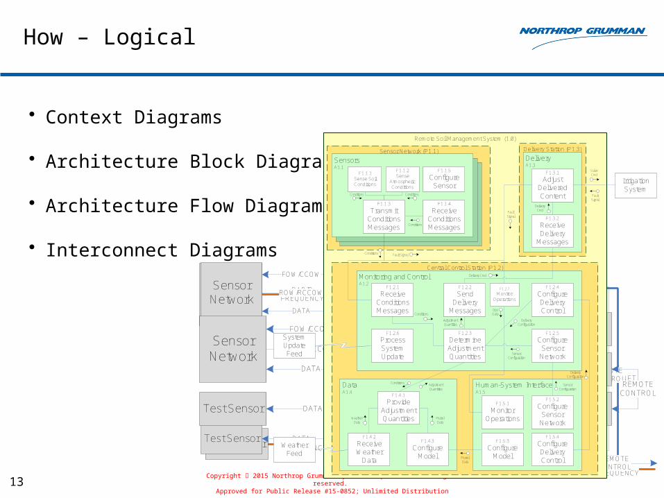
How – Logical
• Context Diagrams
• Architecture Block Diagram
• Architecture Flow Diagrams
• Interconnect Diagrams
Copyright 2015 Northrop Grumman Systems Corporation. All rights reserved. Approved for Public Release #15-0852; Unlimited Distribution
Remote Soil Management System (1.0)
Delivery Station (P1.3)Sensor Network (P1.1)
Central Control Station (P1.2)
SensorsA1.1
Monitoring and ControlA1.2
DeliveryA1.3
Human-System InterfaceA1.5
DataA1.4
Weather Feed
Irrigation System
F1.3.1
Adjust Delivered Content
F1.3.2
Receive Delivery
Messages
F1.2.1
Receive Conditions Messages
F1.2.3
Determine Adjustment Quantities
F1.2.2
Send Delivery
Messages
F1.2.5
Configure Sensor Network
F1.2.4
Configure Delivery Control
F1.1.1Sense Soil Conditions
F1.1.3
Transmit Conditions Messages
F1.1.4
Receive Conditions Messages
F1.4.2
Receive Weather
Data
F1.4.3
Configure Model
F1.4.1
Provide Adjustment Quantities
F1.5.2
Configure Sensor Network
F1.5.4
Configure Delivery Control
F1.5.1
Monitor Operations
F1.5.3
Configure Model
F1.1.5
Configure Sensor
System Update Feed
F1.2.6
Process System Update
Fault Signal
Valve Cmd
Conditions
Conditions
Conditions
Conditions
Delivery Cmd
Delivery Cmd
Adjustment Quantities
Delivery Configuration
Sensor Configuration
Sensor Configuration
Delivery Configuration
F1.2.7
Monitor Operations
Fault Signal
Ops Data
Model Data
Model Data
Weather Data
Adjustment Quantities
Conditions
Fault Signal
F1.1.2Sense
Atmospheric Conditions
Conditions
14
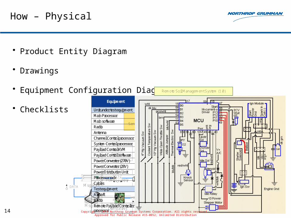
How – Physical
• Product Entity Diagram
• Drawings
• Equipment Configuration Diagrams
• Checklists
Remote Soil Management System (1.0)
P1.1Sensor Network
P1.3Delivery Station
P1.2Central Control
Station
P1.1.1Sensor
P1.1.2Power Supply
P1.1.3Wireless
Transceiver
P1.3.1Valve
P1.3.2Power Supply
P1.3.3Wireless
Transceiver
P1.2.1Computer
P1.2.2Power Supply
P1.2.3Wireless
Transceiver
P1.2.4Internet
ConnectionDATA Tx/Rx Tx/Rx
Msg Proc
DATA
VOICE
Radio
VOICE
DATA +
VOIC
E
DATA +
VOICE
DATA
Msg Sim
Msg Proc DATA
Msg Sim
Radio
Equipment Purpose Quantity Per Site Lab Flight
Unit under test equipment Main Processor General system processors 1 1 Main software General system functionality 1 1 Radio Over-the-air connectivity and message processing 1 1 Antenna Over-the-air connectivity - 1 Channel Control processor Configuration and control of the airborne radios and network 1 1 System Control processor Configuration and control of the airborne system 1 1 Payload Control KVM User interface to the channel and system controllers 1 1 Payload Control software Payload Control functionality 1 1 Power Converter (270V) Converts input power to 270 VDC 1 1 Power Converter (28V) Converts input power to 28 VDC 1 1 Power Distribution Unit Distributes power to DSS hardware components 1 1 Processor rack Houses the DSS airborne B-kit equipment - 1 Cables Provide connections among hardware X X Test equipment Aircraft Platform for the Airborne Segment - 1 Radio Users on the network 2 2 Remote Payload Controller processor Host of the Remote Payload Controller (software) 1 1
Copyright 2015 Northrop Grumman Systems Corporation. All rights reserved.
Approved for Public Release #15-0852; Unlimited Distribution
15
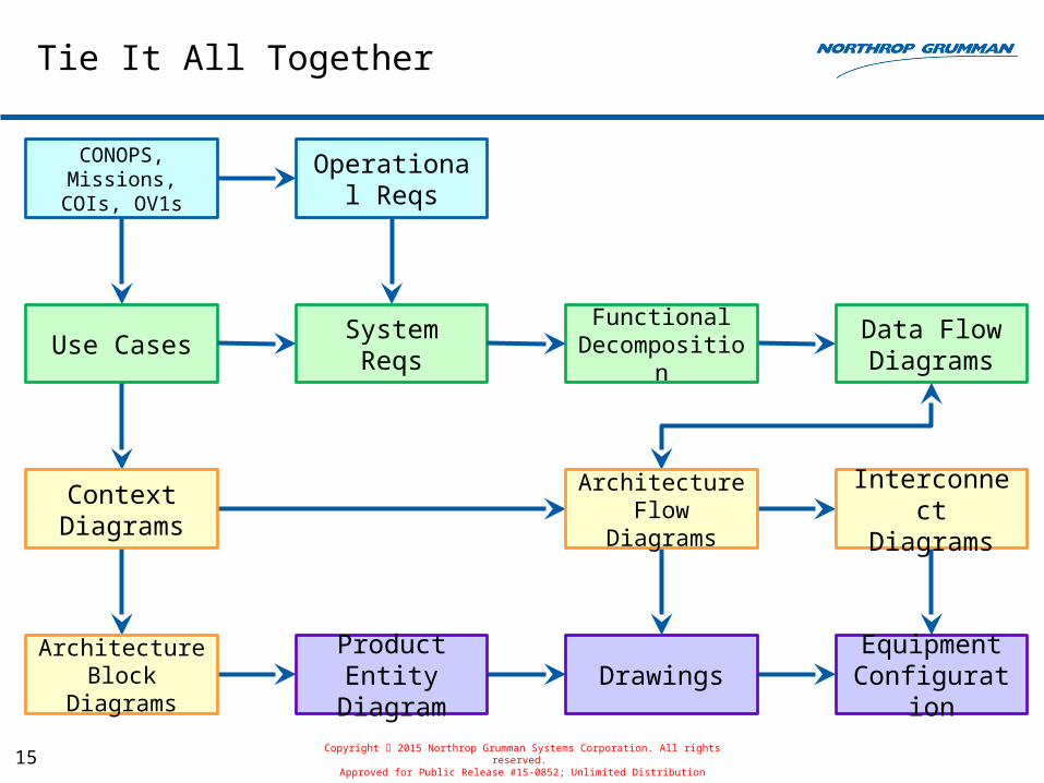
Tie It All Together
Context Diagrams
Use Cases
CONOPS, Missions,
COIs, OV1s
Functional Decomposition
Data Flow Diagrams
Architecture Block Diagrams
Product Entity Diagram
Interconnect Diagrams
DrawingsEquipment
Configuration
Operational Reqs
System Reqs
Copyright 2015 Northrop Grumman Systems Corporation. All rights reserved. Approved for Public Release #15-0852; Unlimited Distribution
Architecture Flow Diagrams
Questions
16Copyright 2015 Northrop Grumman Systems Corporation. All rights reserved.
17
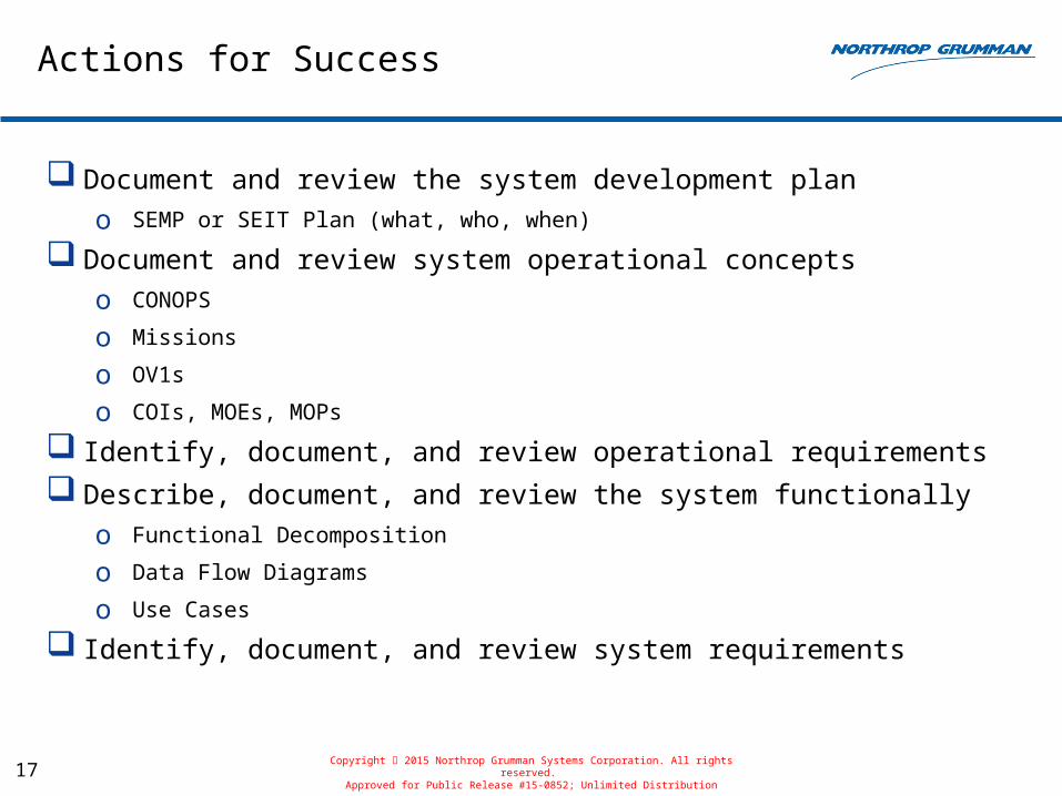
Actions for Success
Document and review the system development plano SEMP or SEIT Plan (what, who, when)
Document and review system operational conceptso CONOPS
o Missions
o OV1s
o COIs, MOEs, MOPs
Identify, document, and review operational requirements
Describe, document, and review the system functionallyo Functional Decomposition
o Data Flow Diagrams
o Use Cases
Identify, document, and review system requirements
Copyright 2015 Northrop Grumman Systems Corporation. All rights reserved. Approved for Public Release #15-0852; Unlimited Distribution
18
Actions for Success (cont.)
Describe, document, and review the system at the logical levelo Context Diagrams
o Architecture Block Diagrams
o Interconnect Diagrams
o Architecture Flow Diagrams
Describe, document, and review the system physicallyo Product Entity Diagrams
o Drawings
o Equipment Configuration Diagrams
Document and review system test and demo plans and procedures
Create and use checklists
Copyright 2015 Northrop Grumman Systems Corporation. All rights reserved. Approved for Public Release #15-0852; Unlimited Distribution

Copyright 2015 Northrop Grumman Systems Corporation. All rights reserved. Approved for Public Release #15-0852; Unlimited Distribution