Embed Size (px)
Citation preview
Advanced Technology Center Slide 1
Model-Based Safety AnalysisOverview
Dr. Steven P. MillerDr. Mats P. E. Heimdahl
Advanced Computing SystemsRockwell Collins
400 Collins Road NE, MS 108-206Cedar Rapids, Iowa 52498
Advanced Technology Center Slide 2
Outline of Presentation
Motivation
Proposed Approach
Demonstration
Analysis
What’s Next
Advanced Technology Center Slide 3
Motivation
Error in FCLSelection Logic
Active FGSSends Incorrect
Guidance Values
Inactive FGSSends Incorrect
Guidance Values
Error Internalto AP
Error Internalto FD
Incorrect GuidanceValues Received
From FGS
IncorrectGuidance
FCL GeneratesIncorrect Guidance
Values
Error in FGSInputs
Error in FCLAlgorithm
Not Shown
Error in FCLSelection Logic
Error in FCLSelection Logic
Active FGSSends Incorrect
Guidance Values
Active FGSSends Incorrect
Guidance Values
Inactive FGSSends Incorrect
Guidance Values
Error Internalto AP
Error Internalto AP
Error Internalto FD
Error Internalto FD
Incorrect GuidanceValues Received
From FGS
Incorrect GuidanceValues Received
From FGS
IncorrectGuidanceIncorrectGuidance
FCL GeneratesIncorrect Guidance
Values
Error in FGSInputs
Error in FCLAlgorithm
FCL GeneratesIncorrect Guidance
Values
FCL GeneratesIncorrect Guidance
Values
Error in FGSInputs
Error in FGSInputs
Error in FCLAlgorithm
Error in FCLAlgorithm
Not Shown
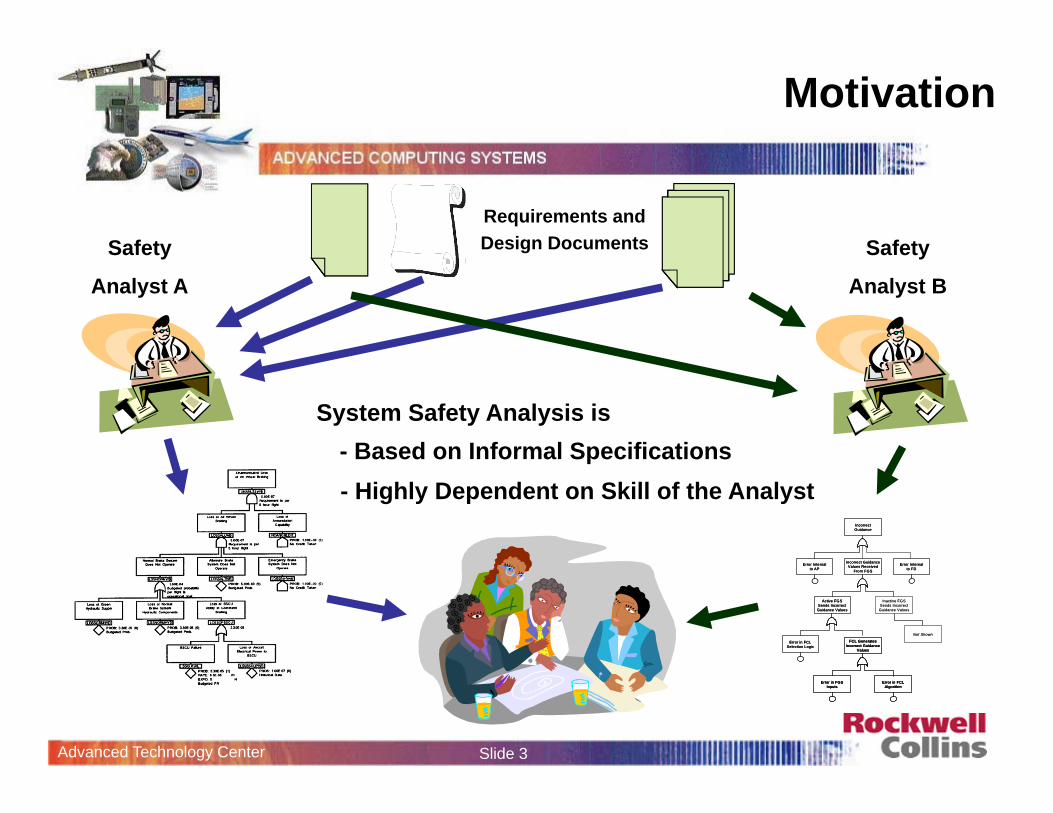
Requirements and Design DocumentsSafety
Analyst A
System Safety Analysis is- Based on Informal Specifications- Highly Dependent on Skill of the Analyst
Safety
Analyst B
Advanced Technology Center Slide 4
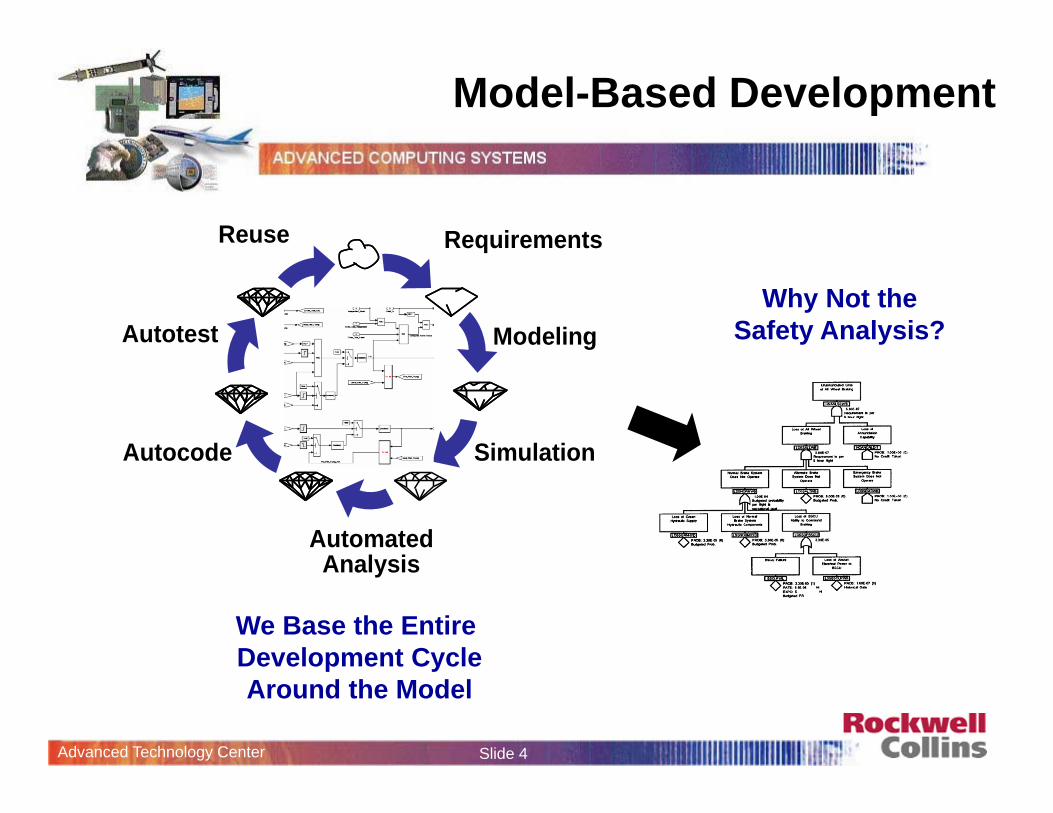
Model-Based Development
Requirements
Modeling
Simulation
AutomatedAnalysis
Autocode
Autotest
Reuse
We Base the Entire Development CycleAround the Model
Why Not theSafety Analysis?
Advanced Technology Center Slide 5
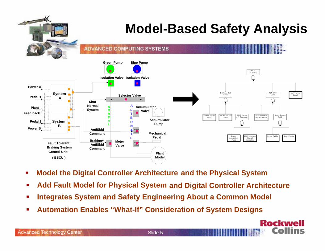
Model-Based Safety Analysis
Add Fault Model for Physical System
Power A
Pedal 1
Feed back Plant
Fault Tolerant
Control Unit
( BSCU )
Braking System
SystemA
Power B
Pedal 2 SystemB
Plant Model
AntiSkid Command
Braking + AntiSkid
Command
Green Pump Blue Pump
Isolation ValveIsolation Valve
Shut Normal System
NORMAL
ALTERNATE
Accumulator Pump
Meter Valve
Meter Valve
Meter Valve
Accumulator Valve
Mechanical Pedal
Selector Valve
Loss AllBraking
Normal SysLoss
Green PumpLoss
Meter ValveLoss
BSCU Lossof Command
PowerSupplies
Fail
BSCU SelectSignal
Inverted
Alt SysLoss
Acc/AS/MechMeter Fails
Both PumpsFail
Blue Fails Acc Fails
SelValveStuck
Model the Digital Controller Architecture
Automation Enables “What-If” Consideration of System Designs
and Digital Controller Architecture Integrates System and Safety Engineering About a Common Model
and the Physical System
Advanced Technology Center Slide 6
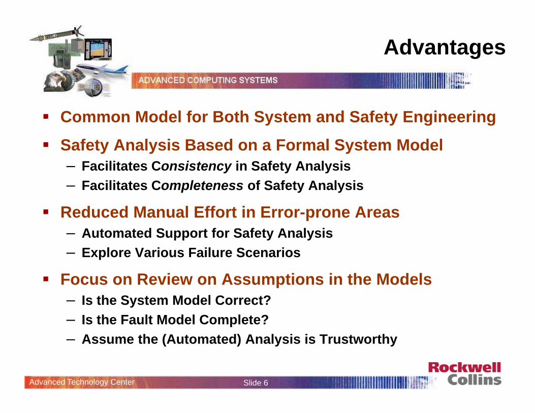
Advantages
Common Model for Both System and Safety Engineering Safety Analysis Based on a Formal System Model
– Facilitates Consistency in Safety Analysis– Facilitates Completeness of Safety Analysis
Reduced Manual Effort in Error-prone Areas– Automated Support for Safety Analysis– Explore Various Failure Scenarios
Focus on Review on Assumptions in the Models– Is the System Model Correct?– Is the Fault Model Complete?– Assume the (Automated) Analysis is Trustworthy
Advanced Technology Center Slide 7
Outline of Presentation
Motivation
Proposed Approach
Demonstration
Analysis
What’s Next
Advanced Technology Center Slide 8
PSSAs SSAs
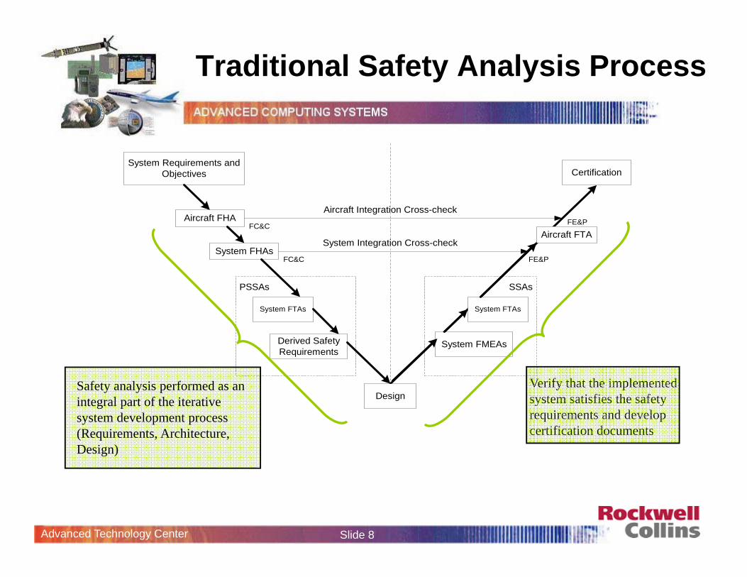
System Requirements andObjectives
Aircraft FHA
System FHAs
System FTAs
Derived SafetyRequirements
Design
System FMEAs
Aircraft FTA
System FTAs
Certification
Aircraft Integration Cross-check
System Integration Cross-check
FC&C
FC&C
FE&P
FE&P
Verify that the implemented system satisfies the safety requirements and develop certification documents
Safety analysis performed as an integral part of the iterative system development process (Requirements, Architecture, Design)
Traditional Safety Analysis Process
Advanced Technology Center Slide 9
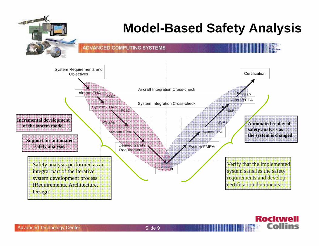
PSSAs SSAs
System Requirements andObjectives
Aircraft FHA
System FHAs
System FTAs
Derived SafetyRequirements
Design
System FMEAs
Aircraft FTA
System FTAs
Certification
Aircraft Integration Cross-check
System Integration Cross-check
FC&C
FC&C
FE&P
FE&P
Verify that the implemented system satisfies the safety requirements and develop certification documents
Safety analysis performed as an integral part of the iterative system development process (Requirements, Architecture, Design)
Model-Based Safety Analysis
Incremental development of the system model.
Support for automatedsafety analysis.
Automated replay ofsafety analysis asthe system is changed.
Advanced Technology Center Slide 10
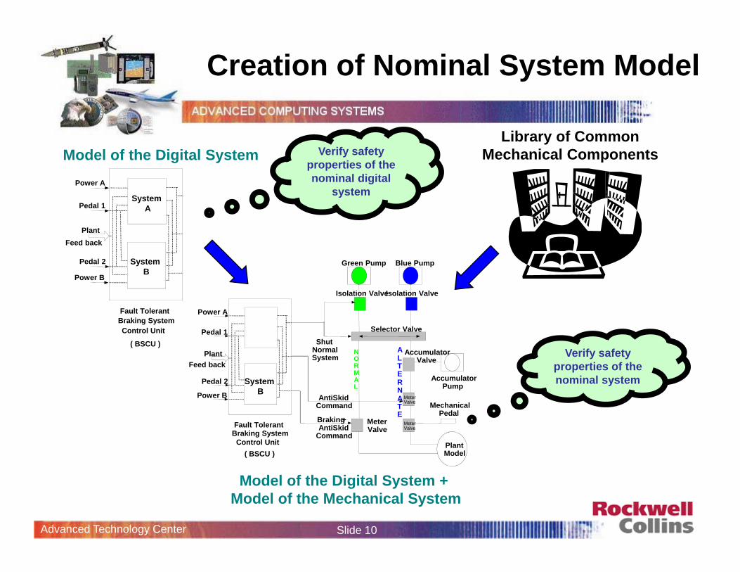
Creation of Nominal System Model
Power A
Pedal 1
Feed back Plant
Fault Tolerant
Control Unit
( BSCU )
Braking System
SystemA
Power B
Pedal 2 SystemB
Model of the Digital System Verify safety properties of the nominal digital
system
Library of Common Mechanical Components
Verify safety properties of the nominal system
Plant Model
AntiSkid Command
Braking + AntiSkid
Command
Green Pump Blue Pump
Isolation ValveIsolation Valve
Shut Normal System
NORMAL
ALTERNATE
Accumulator Pump
Meter Valve
Meter Valve
Meter Valve
Accumulator Valve
Mechanical Pedal
Selector Valve
Power A
Pedal 1
Feed back Plant
Fault Tolerant
Control Unit ( BSCU )
Braking System
Power B
Pedal 2 SystemB
Model of the Digital System + Model of the Mechanical System
Advanced Technology Center Slide 11
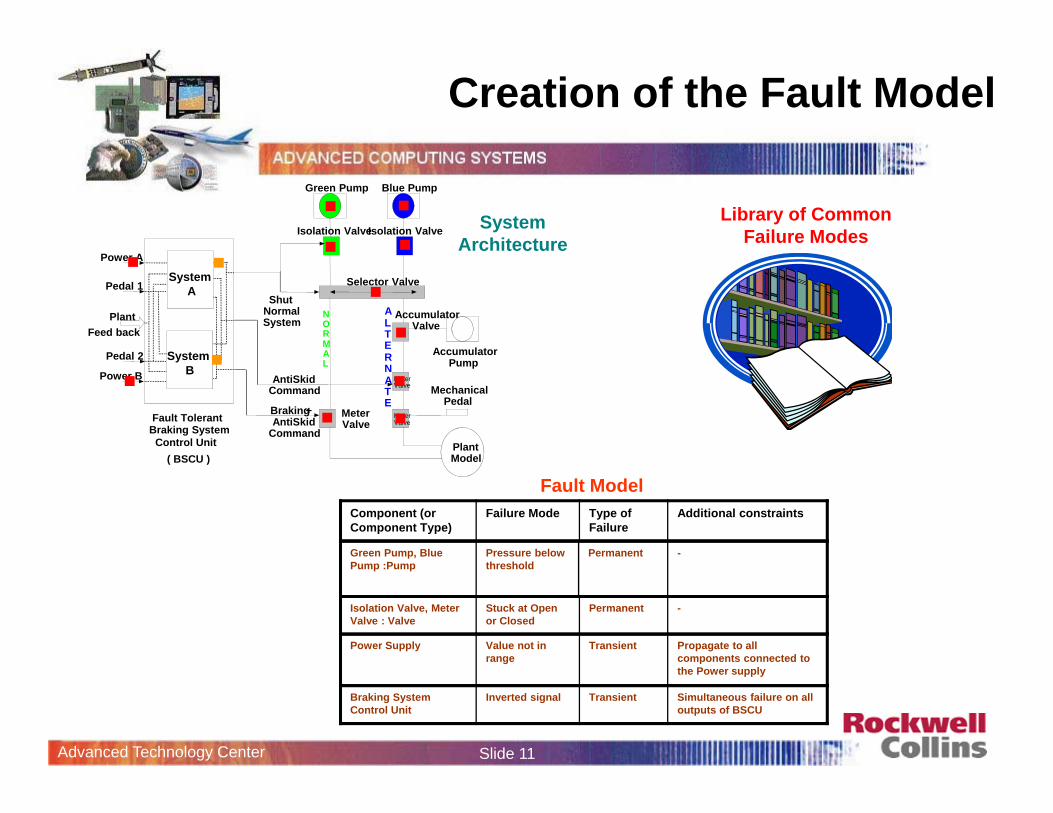
Creation of the Fault Model
Plant Model
AntiSkid Command
Braking + AntiSkid
Command
Green Pump Blue Pump
Isolation ValveIsolation Valve
Shut Normal System
NORMAL
ALTERNATE
Accumulator Pump
Meter Valve
Meter Valve
Meter Valve
Accumulator Valve
Mechanical Pedal
Selector Valve
Power A
Pedal 1
Feed back Plant
Fault Tolerant
Control Unit ( BSCU )
Braking System
SystemA
Power B
Pedal 2 SystemB
Library of Common Failure Modes
Fault Model
System Architecture
Component (or Component Type)
Failure Mode Type of Failure
Additional constraints
Isolation Valve, Meter Valve : Valve
Stuck at Open or Closed
Permanent -
Power Supply Value not in range
Transient Propagate to all components connected to the Power supply
Braking System Control Unit
Inverted signal Transient Simultaneous failure on all outputs of BSCU
Green Pump, Blue Pump :Pump
Pressure below threshold
Permanent -

Advanced Technology Center Slide 12
Auto-generation of Fault Trees
Automated Safety Analysis
FormalizedSafety
Requirements+
Plant Model
AntiSkid Command
Braking + AntiSkid
Command
Green Pump Blue Pump
Isolation ValveIsolation Valve
Shut Normal System
NORMAL
ALTERNATE
Accumulator Pump
Meter Valve
Meter Valve
Meter Valve
Accumulator Valve
Mechanical Pedal
Selector Valve
Power A
Pedal 1
Feed back Plant
Fault Tolerant
Control Unit ( BSCU )
Braking System
SystemA
Power B
Pedal 2 SystemB
Proof Tree for P
P
A is ok
ComponentsA1, A2, A3 all
work asexpected
Connectionsc1,2,c1,3,c2,3are all ok
E1 isok
E2 isok
E3 isok
E is ok
Proofs of Safety Properties
Simulation
Advanced Technology Center Slide 13
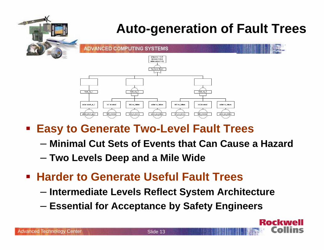
Auto-generation of Fault Trees
Easy to Generate Two-Level Fault Trees– Minimal Cut Sets of Events that Can Cause a Hazard– Two Levels Deep and a Mile Wide
Harder to Generate Useful Fault Trees – Intermediate Levels Reflect System Architecture– Essential for Acceptance by Safety Engineers
Advanced Technology Center Slide 14
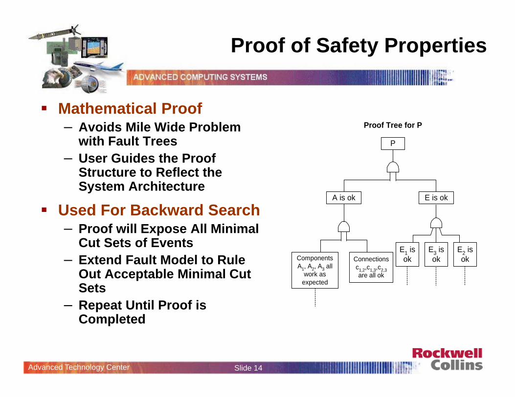
Proof of Safety Properties
Mathematical Proof– Avoids Mile Wide Problem
with Fault Trees– User Guides the Proof
Structure to Reflect the System Architecture
Used For Backward Search– Proof will Expose All Minimal
Cut Sets of Events– Extend Fault Model to Rule
Out Acceptable Minimal Cut Sets
– Repeat Until Proof is Completed
Proof Tree for P
P
A is ok
ComponentsA1, A2, A3 all
work asexpected
Connectionsc1,2,c1,3,c2,3are all ok
E1 isok
E2 isok
E3 isok
E is ok
Advanced Technology Center Slide 15
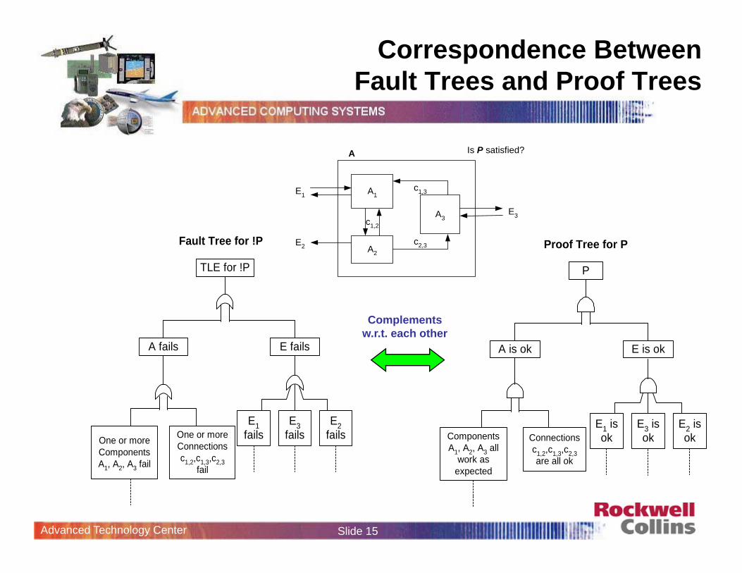
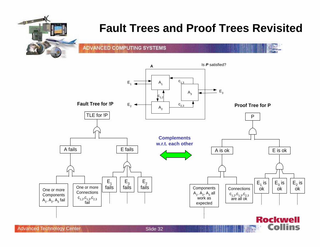
Correspondence Between Fault Trees and Proof Trees
A
A1
A2
A3
c2,3
c1,3E1
E2
E3
Is P satisfied?
c1,2
Fault Tree for !P
TLE for !P
A fails
E1fails
E2fails
E3failsOne or more
ComponentsA1, A2, A3 fail
One or moreConnectionsc1,2,c1,3,c2,3
fail
E fails
Proof Tree for P
P
A is ok
ComponentsA1, A2, A3 all
work asexpected
Connectionsc1,2,c1,3,c2,3are all ok
E1 isok
E2 isok
E3 isok
E is ok
Complements w.r.t. each other
Advanced Technology Center Slide 16
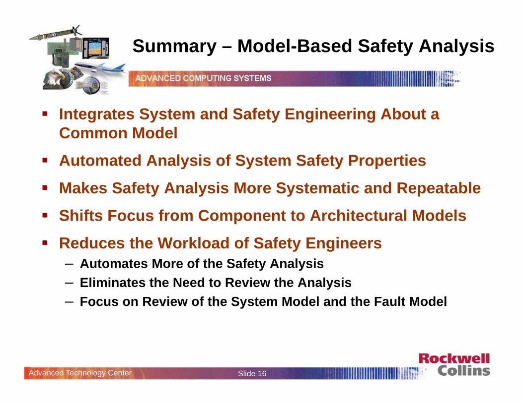
Summary – Model-Based Safety Analysis
Integrates System and Safety Engineering About a Common Model
Automated Analysis of System Safety Properties Makes Safety Analysis More Systematic and Repeatable Shifts Focus from Component to Architectural Models Reduces the Workload of Safety Engineers
– Automates More of the Safety Analysis– Eliminates the Need to Review the Analysis– Focus on Review of the System Model and the Fault Model
Advanced Technology Center Slide 17
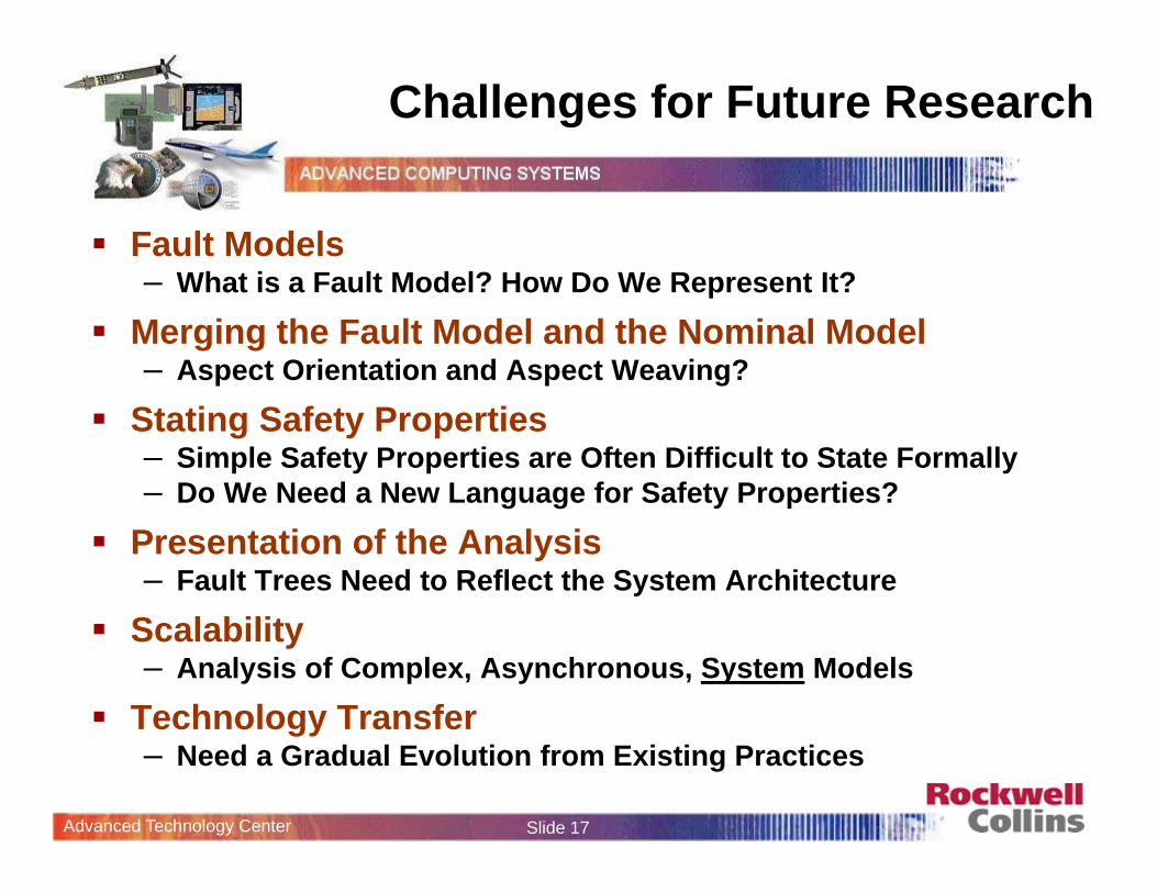
Challenges for Future Research
Fault Models– What is a Fault Model? How Do We Represent It?
Merging the Fault Model and the Nominal Model– Aspect Orientation and Aspect Weaving?
Stating Safety Properties– Simple Safety Properties are Often Difficult to State Formally– Do We Need a New Language for Safety Properties?
Presentation of the Analysis – Fault Trees Need to Reflect the System Architecture
Scalability– Analysis of Complex, Asynchronous, System Models
Technology Transfer– Need a Gradual Evolution from Existing Practices
Advanced Technology Center Slide 18
Model-Based Safety AnalysisDemonstration
Dr. Mats P. E. HeimdahlUniversity of [email protected]
Dr. Steven P. MillerAdvanced Computing Systems
Rockwell [email protected]
Advanced Technology Center Slide 19
Outline of Presentation
Motivation
Proposed Approach
Demonstration
Analysis
What’s Next

Advanced Technology Center Slide 20
Model-Based Safety Analysis
Add Fault Model for Physical System
Power A
Pedal 1
Feed back Plant
Fault Tolerant
Control Unit
( BSCU )
Braking System
SystemA
Power B
Pedal 2 SystemB
Plant Model
AntiSkid Command
Braking + AntiSkid
Command
Green Pump Blue Pump
Isolation ValveIsolation Valve
Shut Normal System
NORMAL
ALTERNATE
Accumulator Pump
Meter Valve
Meter Valve
Meter Valve
Accumulator Valve
Mechanical Pedal
Selector Valve
Loss AllBraking
Normal SysLoss
Green PumpLoss
Meter ValveLoss
BSCU Lossof Command
PowerSupplies
Fail
BSCU SelectSignal
Inverted
Alt SysLoss
Acc/AS/MechMeter Fails
Both PumpsFail
Blue Fails Acc Fails
SelValveStuck
Model the Digital Controller Architecture
Automation Enables “What-If” Consideration of System Designs
and Digital Controller Architecture Integrates System and Safety Engineering About a Common Model
and the Physical System
Advanced Technology Center Slide 21
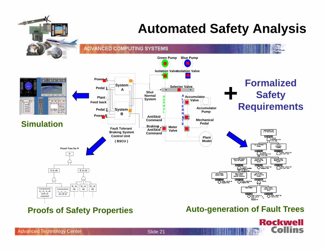
Auto-generation of Fault Trees
Automated Safety Analysis
FormalizedSafety
Requirements+
Plant Model
AntiSkid Command
Braking + AntiSkid
Command
Green Pump Blue Pump
Isolation ValveIsolation Valve
Shut Normal System
NORMAL
ALTERNATE
Accumulator Pump
Meter Valve
Meter Valve
Meter Valve
Accumulator Valve
Mechanical Pedal
Selector Valve
Power A
Pedal 1
Feed back Plant
Fault Tolerant
Control Unit ( BSCU )
Braking System
SystemA
Power B
Pedal 2 SystemB
Proof Tree for P
P
A is ok
ComponentsA1, A2, A3 all
work asexpected
Connectionsc1,2,c1,3,c2,3are all ok
E1 isok
E2 isok
E3 isok
E is ok
Proofs of Safety Properties
Simulation
Advanced Technology Center Slide 22
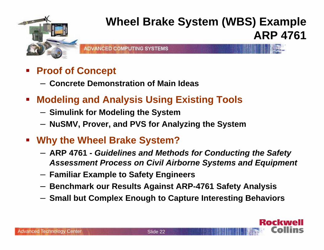
Wheel Brake System (WBS) Example ARP 4761
Proof of Concept– Concrete Demonstration of Main Ideas
Modeling and Analysis Using Existing Tools– Simulink for Modeling the System– NuSMV, Prover, and PVS for Analyzing the System
Why the Wheel Brake System? – ARP 4761 - Guidelines and Methods for Conducting the Safety
Assessment Process on Civil Airborne Systems and Equipment– Familiar Example to Safety Engineers– Benchmark our Results Against ARP-4761 Safety Analysis– Small but Complex Enough to Capture Interesting Behaviors
Advanced Technology Center Slide 23
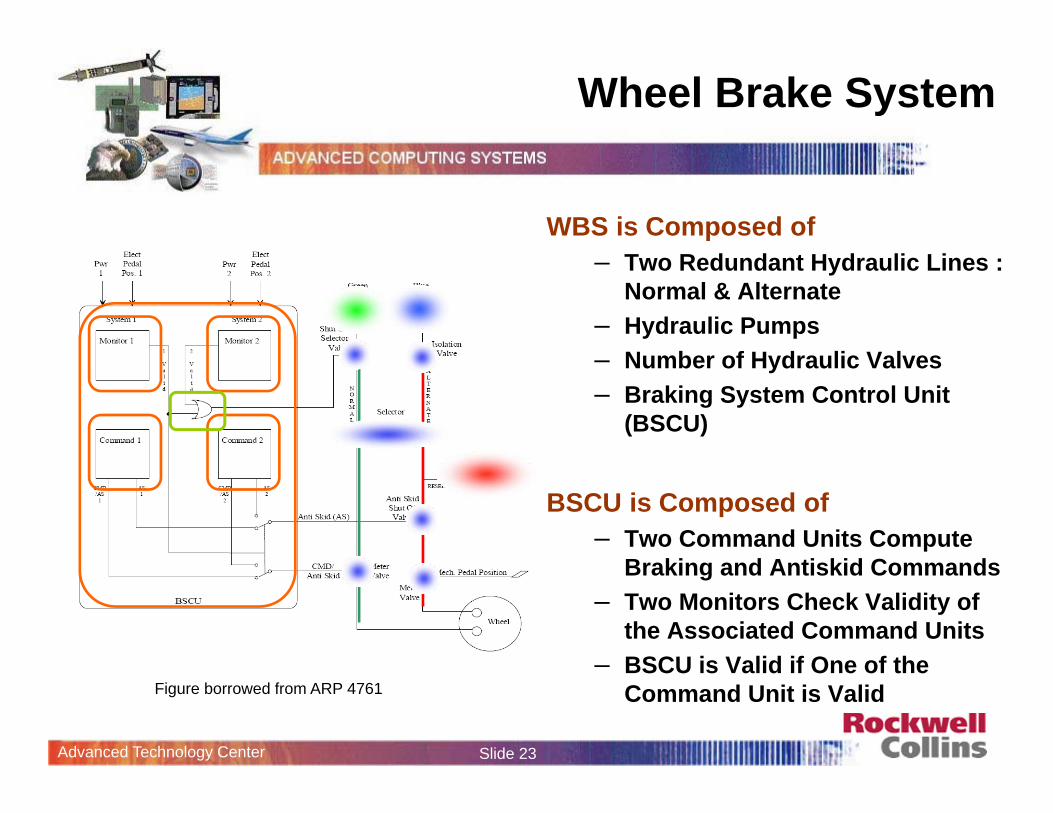
Wheel Brake System
WBS is Composed of– Two Redundant Hydraulic Lines :
Normal & Alternate– Hydraulic Pumps – Number of Hydraulic Valves– Braking System Control Unit
(BSCU)
BSCU is Composed of– Two Command Units Compute
Braking and Antiskid Commands– Two Monitors Check Validity of
the Associated Command Units– BSCU is Valid if One of the
Command Unit is ValidFigure borrowed from ARP 4761
Advanced Technology Center Slide 24
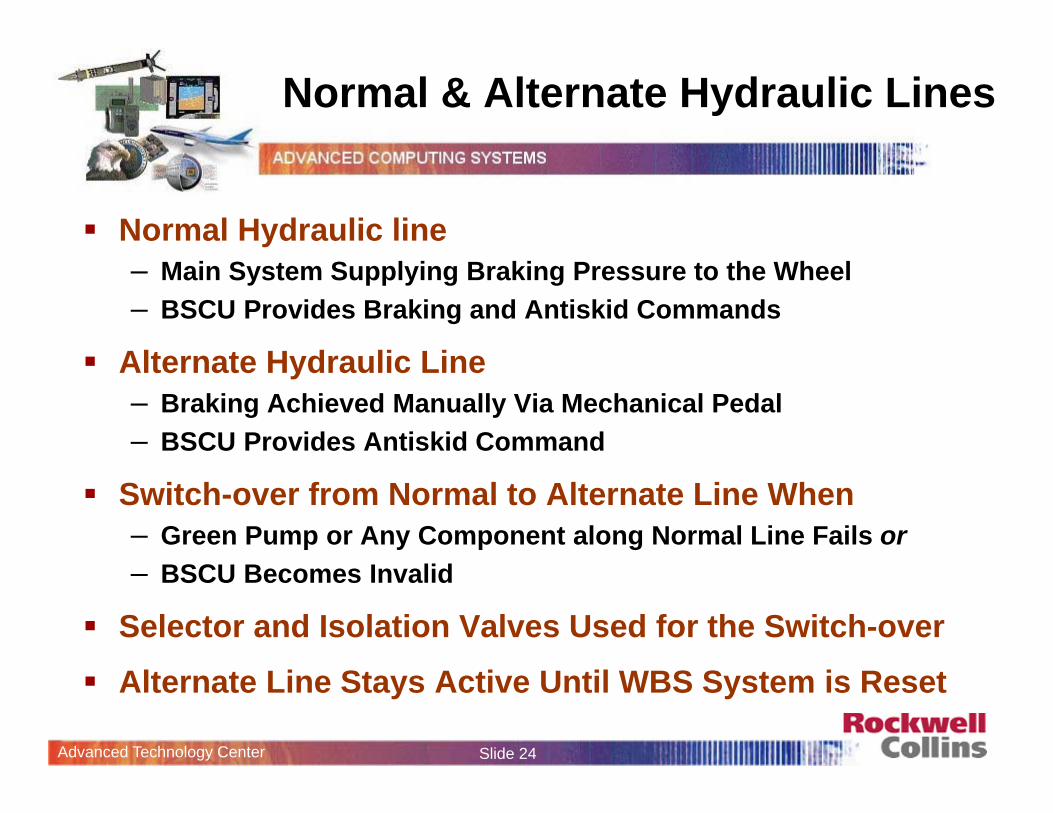
Normal & Alternate Hydraulic Lines
Normal Hydraulic line– Main System Supplying Braking Pressure to the Wheel– BSCU Provides Braking and Antiskid Commands
Alternate Hydraulic Line– Braking Achieved Manually Via Mechanical Pedal– BSCU Provides Antiskid Command
Switch-over from Normal to Alternate Line When– Green Pump or Any Component along Normal Line Fails or– BSCU Becomes Invalid
Selector and Isolation Valves Used for the Switch-over Alternate Line Stays Active Until WBS System is Reset
Advanced Technology Center Slide 25
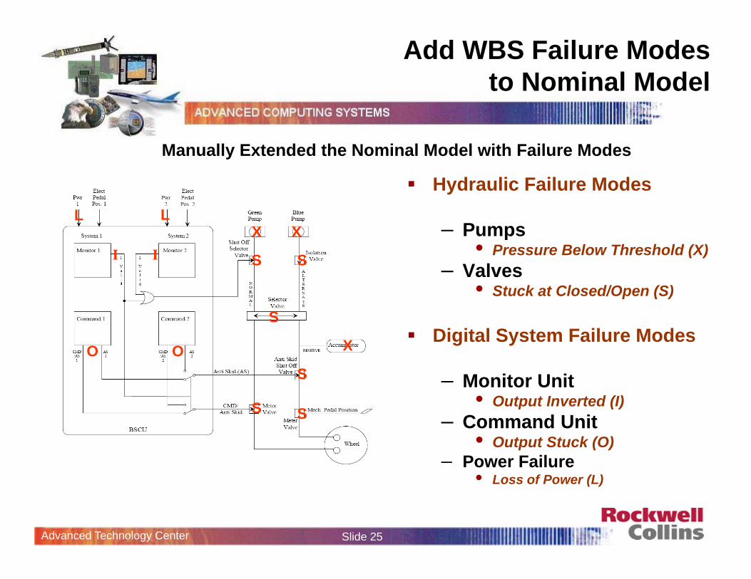
Add WBS Failure Modes to Nominal Model
Hydraulic Failure Modes
– Pumps • Pressure Below Threshold (X)
– Valves• Stuck at Closed/Open (S)
Digital System Failure Modes
– Monitor Unit • Output Inverted (I)
– Command Unit • Output Stuck (O)
– Power Failure• Loss of Power (L)
IX X
X
S S
S
S
S S
O O
I
LL
Manually Extended the Nominal Model with Failure Modes
Advanced Technology Center Slide 26
Outline of Presentation
Motivation
Proposed Approach
Demonstration
Analysis
What’s Next
Advanced Technology Center Slide 27
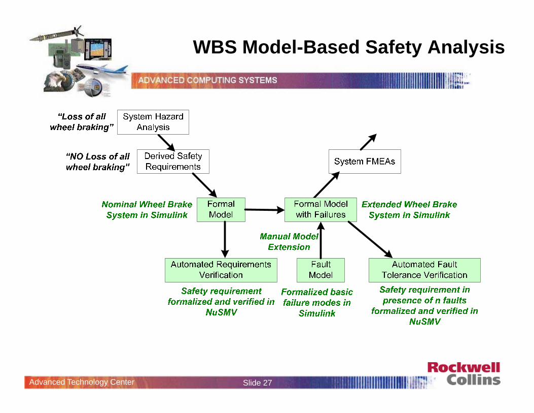
WBS Model-Based Safety Analysis
Advanced Technology Center Slide 28
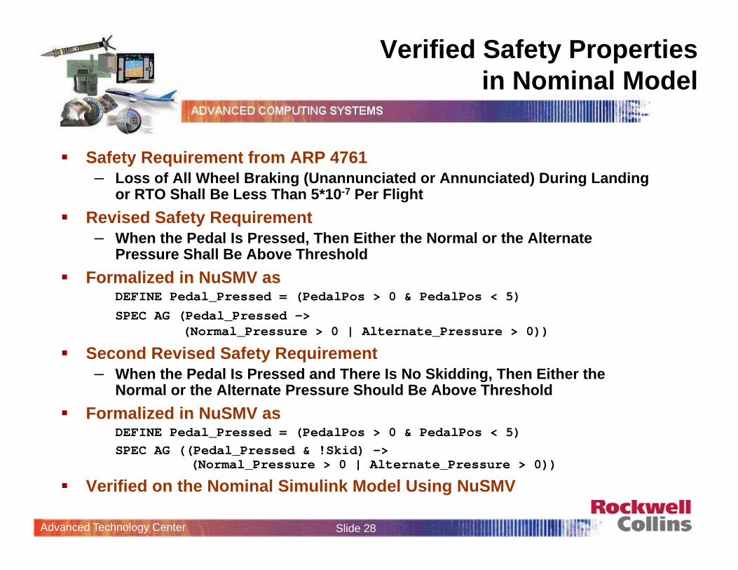
Verified Safety Properties in Nominal Model
Safety Requirement from ARP 4761– Loss of All Wheel Braking (Unannunciated or Annunciated) During Landing
or RTO Shall Be Less Than 5*10-7 Per Flight Revised Safety Requirement
– When the Pedal Is Pressed, Then Either the Normal or the Alternate Pressure Shall Be Above Threshold
Formalized in NuSMV asDEFINE Pedal_Pressed = (PedalPos > 0 & PedalPos < 5) SPEC AG (Pedal_Pressed ->
(Normal_Pressure > 0 | Alternate_Pressure > 0))
Second Revised Safety Requirement – When the Pedal Is Pressed and There Is No Skidding, Then Either the
Normal or the Alternate Pressure Should Be Above Threshold Formalized in NuSMV as
DEFINE Pedal_Pressed = (PedalPos > 0 & PedalPos < 5) SPEC AG ((Pedal_Pressed & !Skid) ->
(Normal_Pressure > 0 | Alternate_Pressure > 0))
Verified on the Nominal Simulink Model Using NuSMV
Advanced Technology Center Slide 29
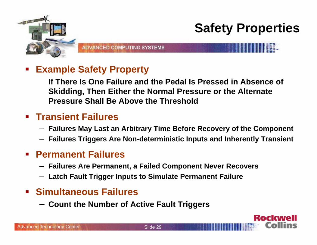
Safety Properties
Example Safety PropertyIf There Is One Failure and the Pedal Is Pressed in Absence of Skidding, Then Either the Normal Pressure or the Alternate Pressure Shall Be Above the Threshold
Transient Failures– Failures May Last an Arbitrary Time Before Recovery of the Component– Failures Triggers Are Non-deterministic Inputs and Inherently Transient
Permanent Failures– Failures Are Permanent, a Failed Component Never Recovers– Latch Fault Trigger Inputs to Simulate Permanent Failure
Simultaneous Failures– Count the Number of Active Fault Triggers
Advanced Technology Center Slide 30
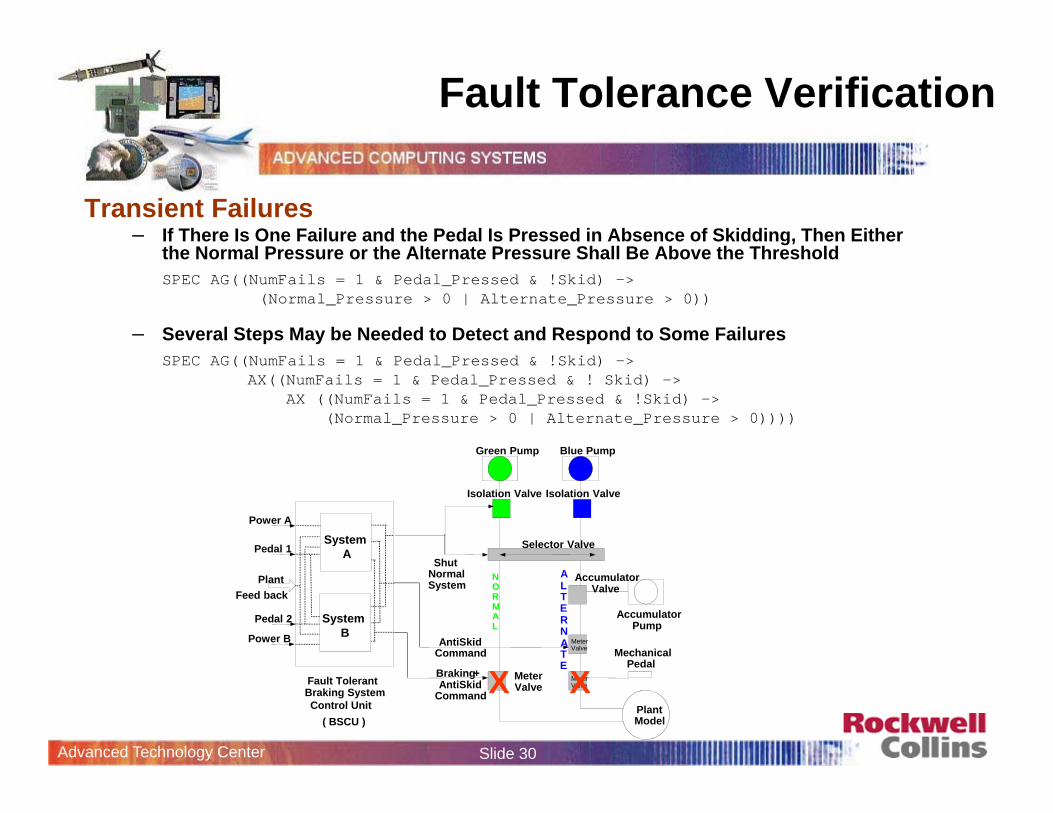
Fault Tolerance Verification
Transient Failures– If There Is One Failure and the Pedal Is Pressed in Absence of Skidding, Then Either
the Normal Pressure or the Alternate Pressure Shall Be Above the ThresholdSPEC AG((NumFails = 1 & Pedal_Pressed & !Skid) ->
(Normal_Pressure > 0 | Alternate_Pressure > 0))
– Several Steps May be Needed to Detect and Respond to Some FailuresSPEC AG((NumFails = 1 & Pedal_Pressed & !Skid) –>
AX((NumFails = 1 & Pedal_Pressed & ! Skid) –>AX ((NumFails = 1 & Pedal_Pressed & !Skid) ->
(Normal_Pressure > 0 | Alternate_Pressure > 0))))
Plant Model
AntiSkid Command
Braking + AntiSkid
Command
Green Pump Blue Pump
Isolation ValveIsolation Valve
Shut Normal System
NORMAL
ALTERNATE
Accumulator Pump
Meter Valve
Meter Valve
Meter Valve
Accumulator Valve
Mechanical Pedal
Selector Valve
Power A
Pedal 1
Feed back Plant
Fault Tolerant
Control Unit ( BSCU )
Braking System
SystemA
Power B
Pedal 2 SystemB
X X
Advanced Technology Center Slide 31
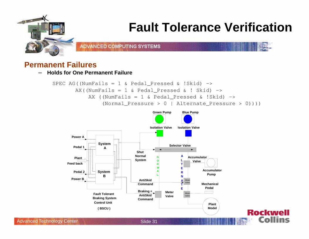
Fault Tolerance Verification
Permanent Failures– Holds for One Permanent Failure
SPEC AG((NumFails = 1 & Pedal_Pressed & !Skid) –> AX((NumFails = 1 & Pedal_Pressed & ! Skid) –>
AX ((NumFails = 1 & Pedal_Pressed & !Skid) -> (Normal_Pressure > 0 | Alternate_Pressure > 0))))
Plant Model
AntiSkid Command
Braking + AntiSkid
Command
Green Pump Blue Pump
Isolation ValveIsolation Valve
Shut Normal System
NORMAL
ALTERNATE
Accumulator Pump
Meter Valve
Meter Valve
Meter Valve
Accumulator Valve
Mechanical Pedal
Selector Valve
Power A
Pedal 1
Feed back
Plant
Fault Tolerant
Control Unit
( BSCU )
Braking System
SystemA
Power B
Pedal 2 SystemB
Advanced Technology Center Slide 32
Fault Trees and Proof Trees Revisited
A
A1
A2
A3
c2,3
c1,3E1
E2
E3
Is P satisfied?
c1,2
Fault Tree for !P
TLE for !P
A fails
E1fails
E2fails
E3failsOne or more
ComponentsA1, A2, A3 fail
One or moreConnectionsc1,2,c1,3,c2,3
fail
E fails
Proof Tree for P
P
A is ok
ComponentsA1, A2, A3 all
work asexpected
Connectionsc1,2,c1,3,c2,3are all ok
E1 isok
E2 isok
E3 isok
E is ok
Complements w.r.t. each other
Advanced Technology Center Slide 33
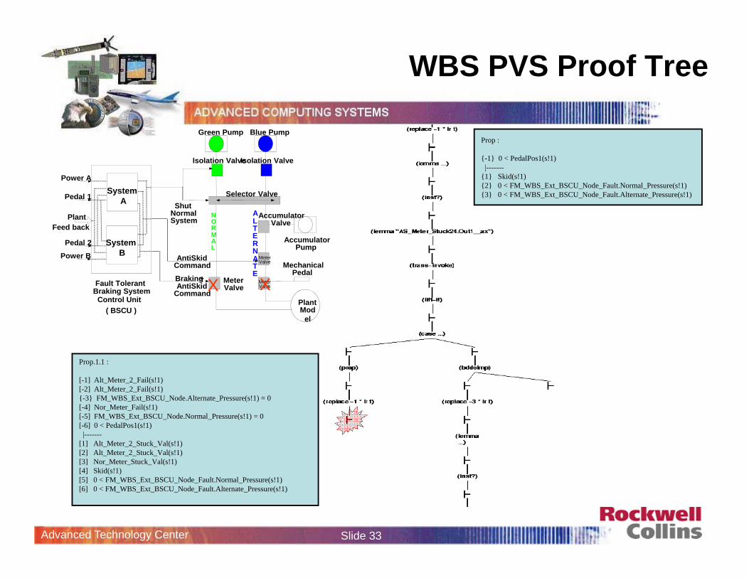
WBS PVS Proof Tree
Prop.1.1 :
[-1] Alt_Meter_2_Fail(s!1)[-2] Alt_Meter_2_Fail(s!1){-3} FM_WBS_Ext_BSCU_Node.Alternate_Pressure(s!1) = 0[-4] Nor_Meter_Fail(s!1)[-5] FM_WBS_Ext_BSCU_Node.Normal_Pressure(s!1) = 0[-6] 0 < PedalPos1(s!1)
|-------[1] Alt_Meter_2_Stuck_Val(s!1)[2] Alt_Meter_2_Stuck_Val(s!1)[3] Nor_Meter_Stuck_Val(s!1)[4] Skid(s!1)[5] 0 < FM_WBS_Ext_BSCU_Node_Fault.Normal_Pressure(s!1)[6] 0 < FM_WBS_Ext_BSCU_Node_Fault.Alternate_Pressure(s!1)
Plant Mod
el
AntiSkid Command
Braking + AntiSkid
Command
Green Pump Blue Pump
Isolation ValveIsolation Valve
Shut Normal System
NORMAL
ALTERNATE
Accumulator Pump
Meter Valve
Meter Valve
Meter Valve
Accumulator Valve
Mechanical Pedal
Selector Valve
Power A
Pedal 1
Feed back Plant
Fault Tolerant
Control Unit ( BSCU )
Braking System
SystemA
Power BPedal 2 System
B
X X
Prop :
{-1} 0 < PedalPos1(s!1)|-------
{1} Skid(s!1){2} 0 < FM_WBS_Ext_BSCU_Node_Fault.Normal_Pressure(s!1){3} 0 < FM_WBS_Ext_BSCU_Node_Fault.Alternate_Pressure(s!1)
Advanced Technology Center Slide 34
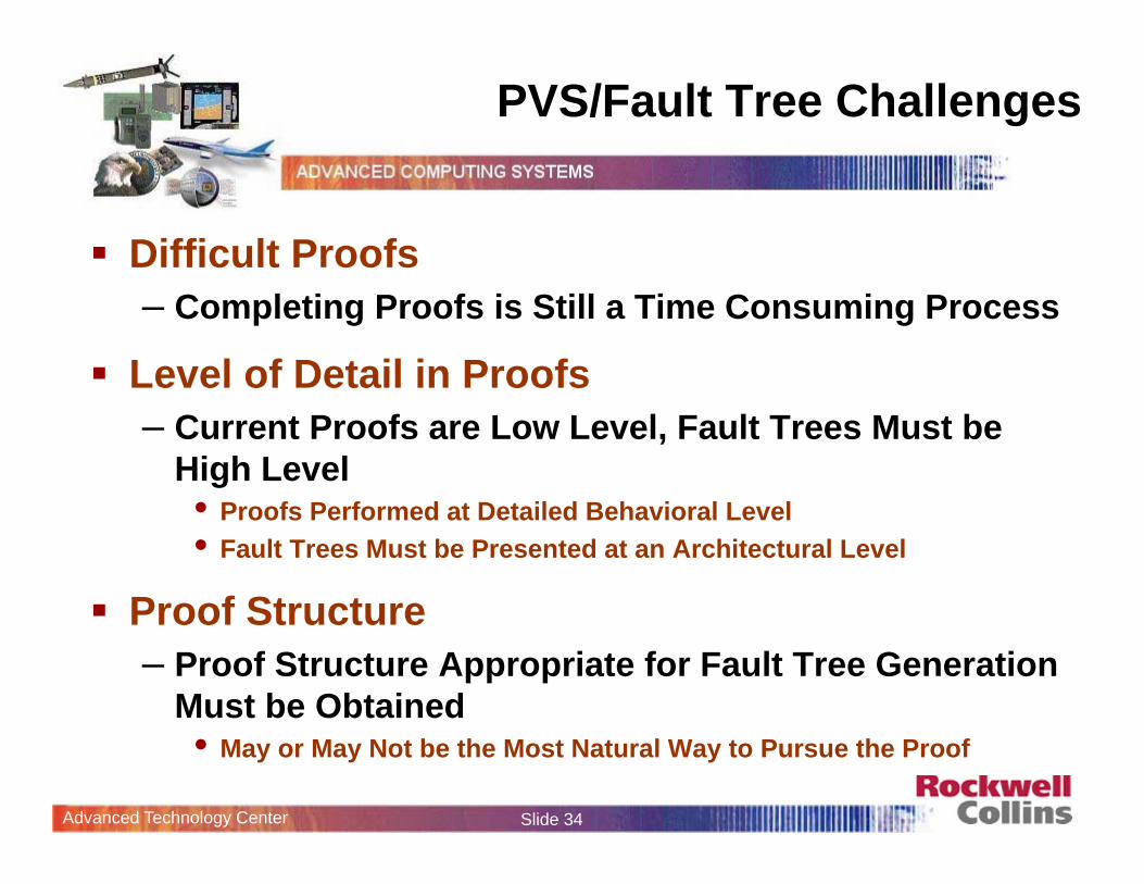
PVS/Fault Tree Challenges
Difficult Proofs– Completing Proofs is Still a Time Consuming Process
Level of Detail in Proofs– Current Proofs are Low Level, Fault Trees Must be
High Level• Proofs Performed at Detailed Behavioral Level• Fault Trees Must be Presented at an Architectural Level
Proof Structure– Proof Structure Appropriate for Fault Tree Generation
Must be Obtained• May or May Not be the Most Natural Way to Pursue the Proof
Advanced Technology Center Slide 35
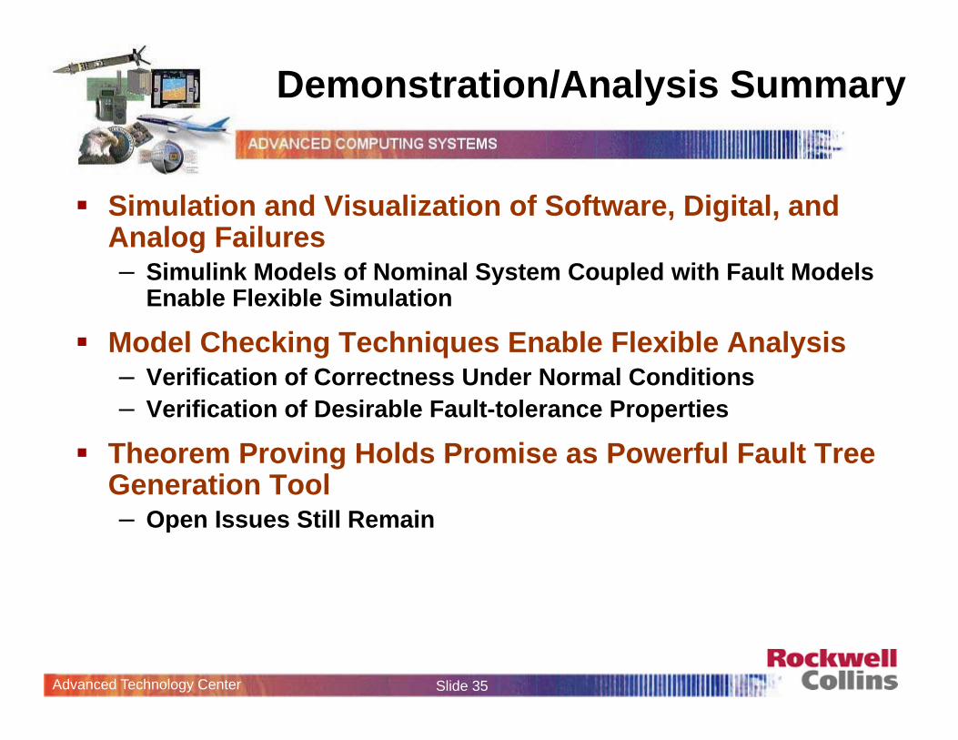
Demonstration/Analysis Summary
Simulation and Visualization of Software, Digital, and Analog Failures– Simulink Models of Nominal System Coupled with Fault Models
Enable Flexible Simulation
Model Checking Techniques Enable Flexible Analysis– Verification of Correctness Under Normal Conditions– Verification of Desirable Fault-tolerance Properties
Theorem Proving Holds Promise as Powerful Fault Tree Generation Tool– Open Issues Still Remain
Advanced Technology Center Slide 36
Outline of Presentation
Motivation
Proposed Approach
Demonstration
Analysis
What’s Next
Advanced Technology Center Slide 37
What’s Next
Improving Modeling Process Ease of Analysis Presentation of Analysis Results Scalability
Advanced Technology Center Slide 38
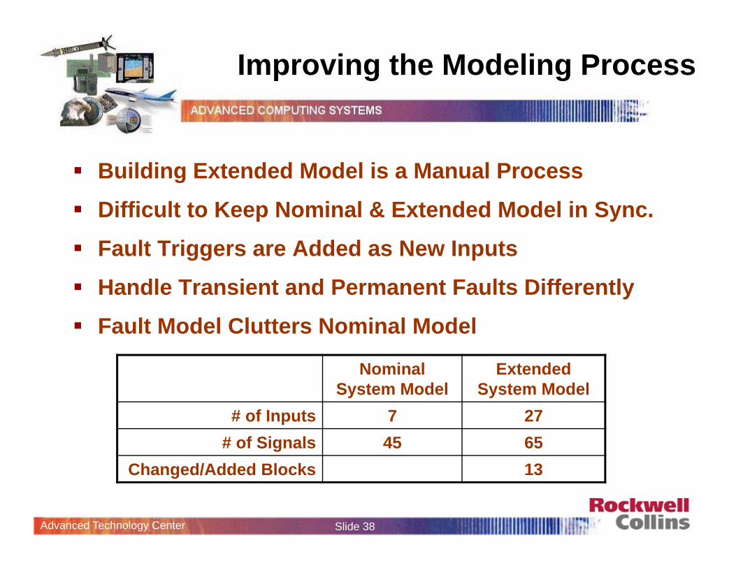
Improving the Modeling Process
Nominal System Model
Extended System Model
# of Inputs 7 27# of Signals 45 65
Changed/Added Blocks 13
Building Extended Model is a Manual Process Difficult to Keep Nominal & Extended Model in Sync. Fault Triggers are Added as New Inputs Handle Transient and Permanent Faults Differently Fault Model Clutters Nominal Model
Advanced Technology Center Slide 39
Improving the Modeling Process
3System _M ode
2Al te rna te_Pressure
1Norm al_P ressure
z
1
z
1
z
1
Stuc
k_Fl
ag
Stuc
k_at
_Val
Sel_
Activ
e
Nor
_In
Alt_
In
Nor
_Out
Alt_
Out
S e lecto r_S tuck
Pum p_Fai l2
Pwr_F ailPwrOut
Power_Fa i l1
Pwr_F ailPwrOut
Power_Fa i l
Stuc
k_Fl
ag
Stuc
k_at
_Val
Pres
sure
Cm
d
Out
1
M e te r_S tuck
PosC m d
M echan ica lP eda l
NOT
Inverted
Gree n Pum p_ Fai l
Stuc
k_Fl
ag
Stuc
k_at
_Val
Valv
e_Sh
ut
Pres
sure
Out
1
G ree n Pum pIso la tio n_Stuck
[Green_ T ag]
[Nor_Out]
[A l t_A cti ve ]
[A l tP_Fee dback][NorP_Fe edback]
[NorV a lve Cm d]
[A l tVa lveCm d]
[Acc_T ag]
[B lue_T ag]
GP _Fa i
V_Fa i l ]
[A l tP_Fe edback]
[Nor_Out]
[A l t_Active ]
[NorP _Feedback]
_Stuck_
_M e ter_
[Gre en_T ag ]
wr2_Fa i
M 2_Va l
wr1_Fa
[NorV a lveCm d]
M 2 _Fa i
[S _Val ][S_ Fa i l ]
B I_Fa i l
B I_Va l ]G I_V a l
G I_Fa i l
[A l tVa lveCm d]
_ AM _V
_A M _F
M _V al
M _Fa i
AP _Fa i l
BP_ Fa i l ]
[Acc_T ag]
[B l ue_T ag]
Stuc
k_Fl
ag
Stuc
k_at
_Val
Pres
sure
Cm
d
Out
1
CM D/AS M eter_S tuck
Blue P um p_Fa i l
Stuc
k_Fl
ag
Stuc
k_at
_Val
Valv
e_Sh
ut
Pres
sure
Out
1
B lue P um pIso la tion_S tuck
Pwr1
Pwr2
Pedal1
Pedal2
AutoBrakeOn
D ecR ate
AC _Speed
Sk id
N or_Pressure
Alt_Pressure
Green_Pressure
Blue_Pressure
Acc_Pressure
Out_N orP
Sel_Alt
N or_C m d
Alt_C m d
Sy stem Mode
BS CU
Pipe
Pres
sure
Res
erve
Pres
sure
AltA
ctiv
e
Stuc
k_Fl
ag
Stuc
k_Va
l
Pres
sure
_OutAccu m ula to rV a lve_Stuck
Stuc
k_Fl
ag
Stuc
k_at
_Val
Pres
sure
Cm
d
Out
1
ASM eter_S tuck
7AC_ Speed
6Skid
5DecRate
4AutoB rake
3M echP eda l
2P eda lP os2
1P eda lP os1
3System_Mode
2Alternate_Pressure
1Normal_Pressure
z
1
z
1
z
1
Unit Delay
Sele
ctor
Off
Nor
_Pre
ssur
e
Alt_
Pres
sure
Nor
_Pre
ssur
e_O
ut
Alt_
Pres
sure
_Out
SelectorValve
ValidPower
ValidPower
PosCmd
MechanicalPedal
Pipe
Pre
ssur
e_In
Cm
dPos
Pipe
Pre
ssur
e_O
ut
ManualMeterValve
NOT
Valv
eShu
t
Pipe
Pre
ssur
eP
ress
ure_
OutGreen Pump
IsolationValve
GreenPump
[Green_P]
[Acc_P]
[Alt_Active]
[AltP_Feedback][NorP_Feedback]
[NorValveCmd]
[AltValveCmd]
[Nor_Out]
[Blue_P]
[Nor_Out]
[Acc_P]
[Alt_Active]
[AltP_Feedback]
[NorP_Feedback]
[NorValveCmd]
[AltValveCmd]
[Green_P]
[Blue_P]
Pipe
Pre
ssur
e_In
Cm
dPos
Pipe
Pre
ssur
e_O
ut
CMD/ASMeterValve
Valv
eShu
t
Pipe
Pre
ssur
eP
ress
ure_
OutBlue Pump
IsolationValve
BluePump
Pwr1
Pwr2
Pedal1
Pedal2
AutoBrakeOn
DecRate
AC_Speed
Skid
Nor_Pressure
Alt_Pressure
Green_Pressure
Blue_Pressure
Acc_Pressure
Out_NorP
Sel_Alt
Nor_Cmd
Alt_Cmd
SystemMode
BSCU
Pip
ePre
ssur
e
Res
Pres
sure
AltA
ctiv
e
Pipe
Pre
ssur
e_O
utAccumulatorValve
Accumulator Pump
Pip
ePre
ssur
e_In
Cm
dPos
Pip
ePre
ssur
e_O
ut
ASMeterValve
7AC_Speed
6Skid
5DecRate
4AutoBrake
3MechPedal
2PedalPos2
1PedalPos1
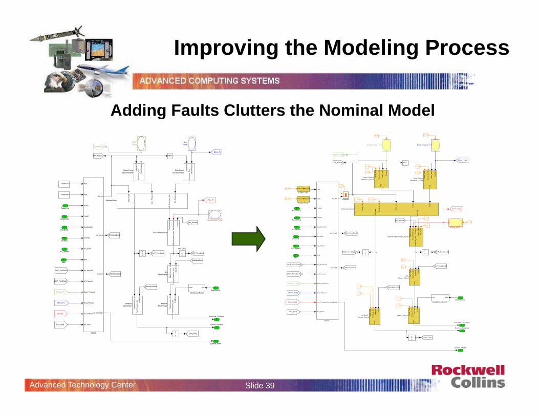
Adding Faults Clutters the Nominal Model
Advanced Technology Center Slide 40
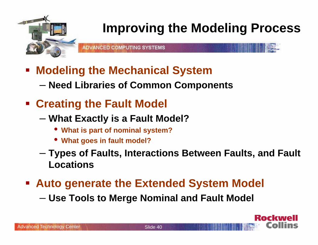
Improving the Modeling Process
Modeling the Mechanical System– Need Libraries of Common Components
Creating the Fault Model– What Exactly is a Fault Model?
• What is part of nominal system? • What goes in fault model?
– Types of Faults, Interactions Between Faults, and Fault Locations
Auto generate the Extended System Model– Use Tools to Merge Nominal and Fault Model
Advanced Technology Center Slide 41
Improving the Modeling Process
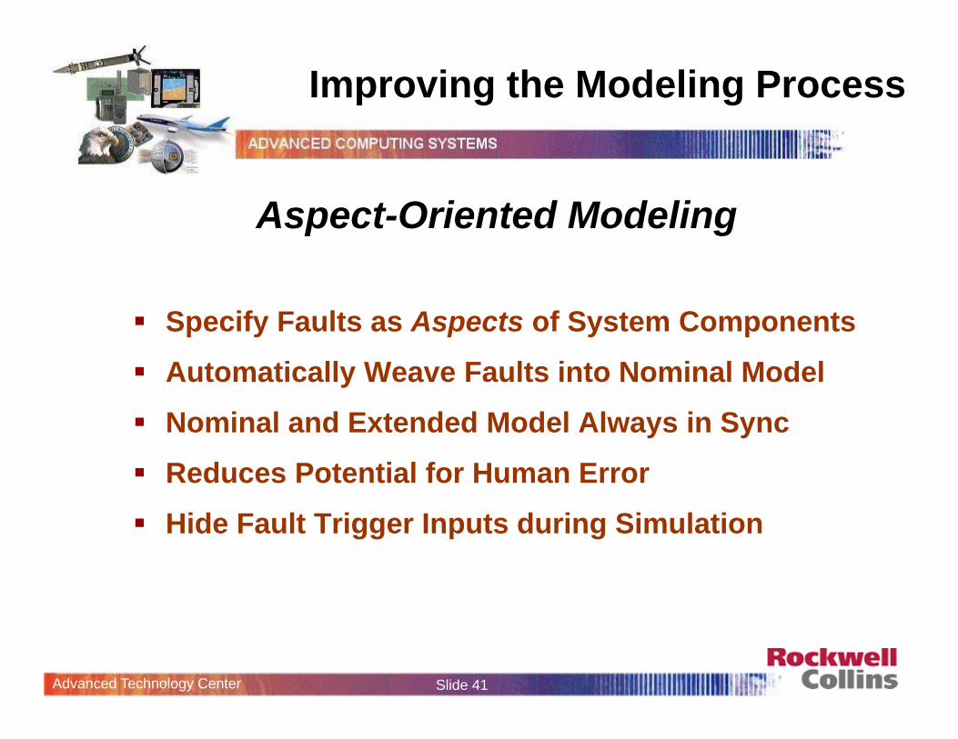
Aspect-Oriented Modeling
Specify Faults as Aspects of System Components Automatically Weave Faults into Nominal Model Nominal and Extended Model Always in Sync Reduces Potential for Human Error Hide Fault Trigger Inputs during Simulation
Advanced Technology Center Slide 42
Ease of Analysis
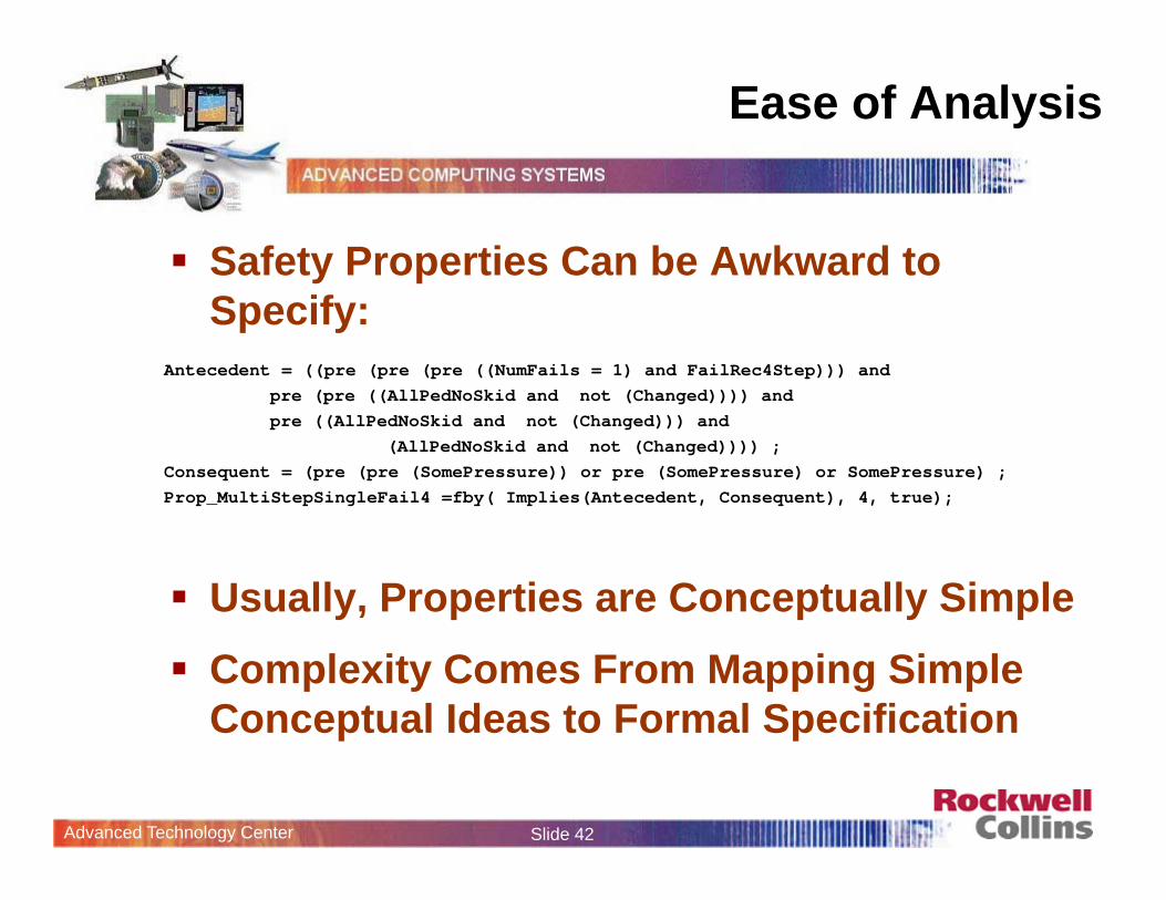
Safety Properties Can be Awkward to Specify:
Usually, Properties are Conceptually Simple Complexity Comes From Mapping Simple
Conceptual Ideas to Formal Specification
Antecedent = ((pre (pre (pre ((NumFails = 1) and FailRec4Step))) andpre (pre ((AllPedNoSkid and not (Changed)))) and pre ((AllPedNoSkid and not (Changed))) and
(AllPedNoSkid and not (Changed)))) ;Consequent = (pre (pre (SomePressure)) or pre (SomePressure) or SomePressure) ;Prop_MultiStepSingleFail4 =fby( Implies(Antecedent, Consequent), 4, true);
Advanced Technology Center Slide 43
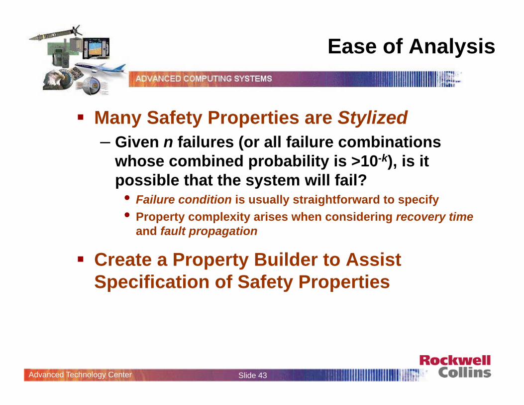
Ease of Analysis
Many Safety Properties are Stylized– Given n failures (or all failure combinations
whose combined probability is >10-k), is it possible that the system will fail?• Failure condition is usually straightforward to specify• Property complexity arises when considering recovery time
and fault propagation
Create a Property Builder to Assist Specification of Safety Properties
Advanced Technology Center Slide 44
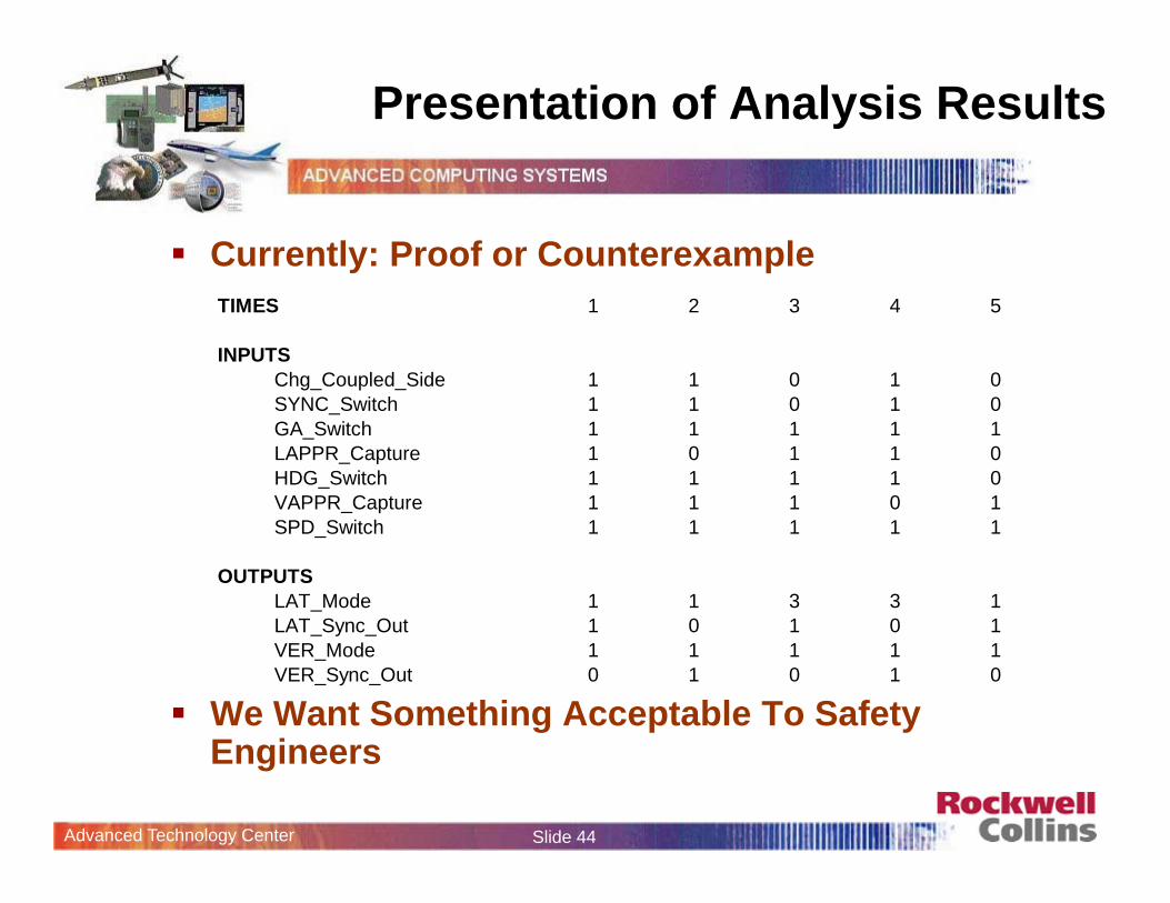
Presentation of Analysis Results
Currently: Proof or Counterexample
We Want Something Acceptable To Safety Engineers
TIMES 1 2 3 4 5
INPUTSChg_Coupled_Side 1 1 0 1 0SYNC_Switch 1 1 0 1 0GA_Switch 1 1 1 1 1LAPPR_Capture 1 0 1 1 0HDG_Switch 1 1 1 1 0VAPPR_Capture 1 1 1 0 1SPD_Switch 1 1 1 1 1
OUTPUTSLAT_Mode 1 1 3 3 1LAT_Sync_Out 1 0 1 0 1VER_Mode 1 1 1 1 1VER_Sync_Out 0 1 0 1 0
Advanced Technology Center Slide 45
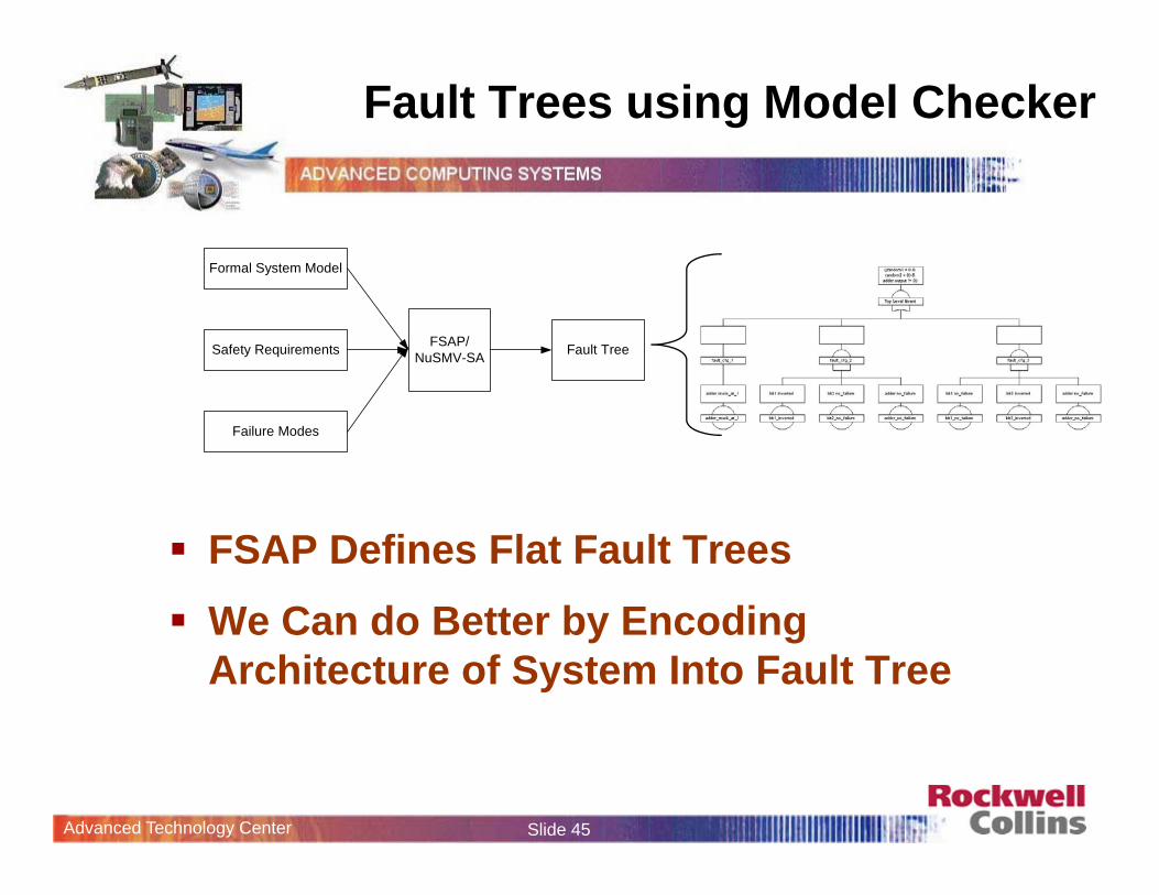
Fault Trees using Model Checker
FSAP Defines Flat Fault Trees We Can do Better by Encoding
Architecture of System Into Fault Tree
Formal System Model
Safety Requirements
Failure Modes
FSAP/NuSMV-SA Fault Tree
Advanced Technology Center Slide 46
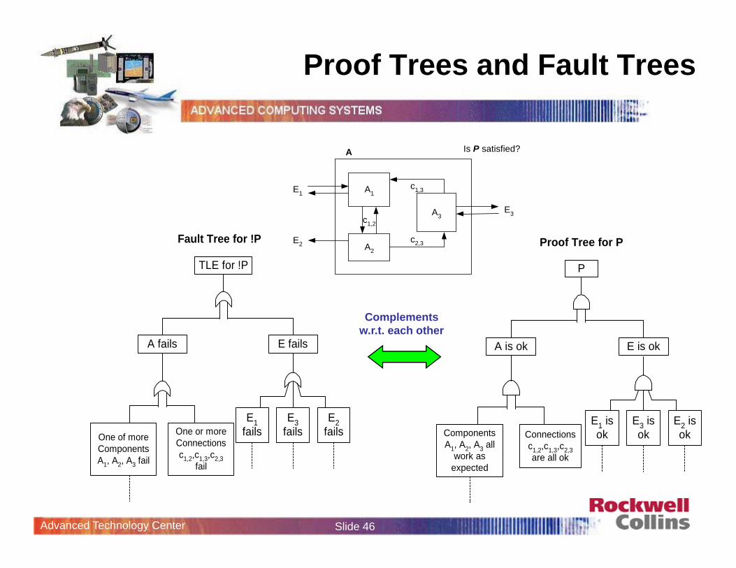
Proof Trees and Fault Trees
A
A1
A2
A3
c2,3
c1,3E1
E2
E3
Is P satisfied?
c1,2
Fault Tree for !P
TLE for !P
A fails
E1fails
E2fails
E3failsOne of more
ComponentsA1, A2, A3 fail
One or moreConnectionsc1,2,c1,3,c2,3
fail
E fails
Proof Tree for P
P
A is ok
ComponentsA1, A2, A3 all
work asexpected
Connectionsc1,2,c1,3,c2,3are all ok
E1 isok
E2 isok
E3 isok
E is ok
Complements w.r.t. each other
Advanced Technology Center Slide 47
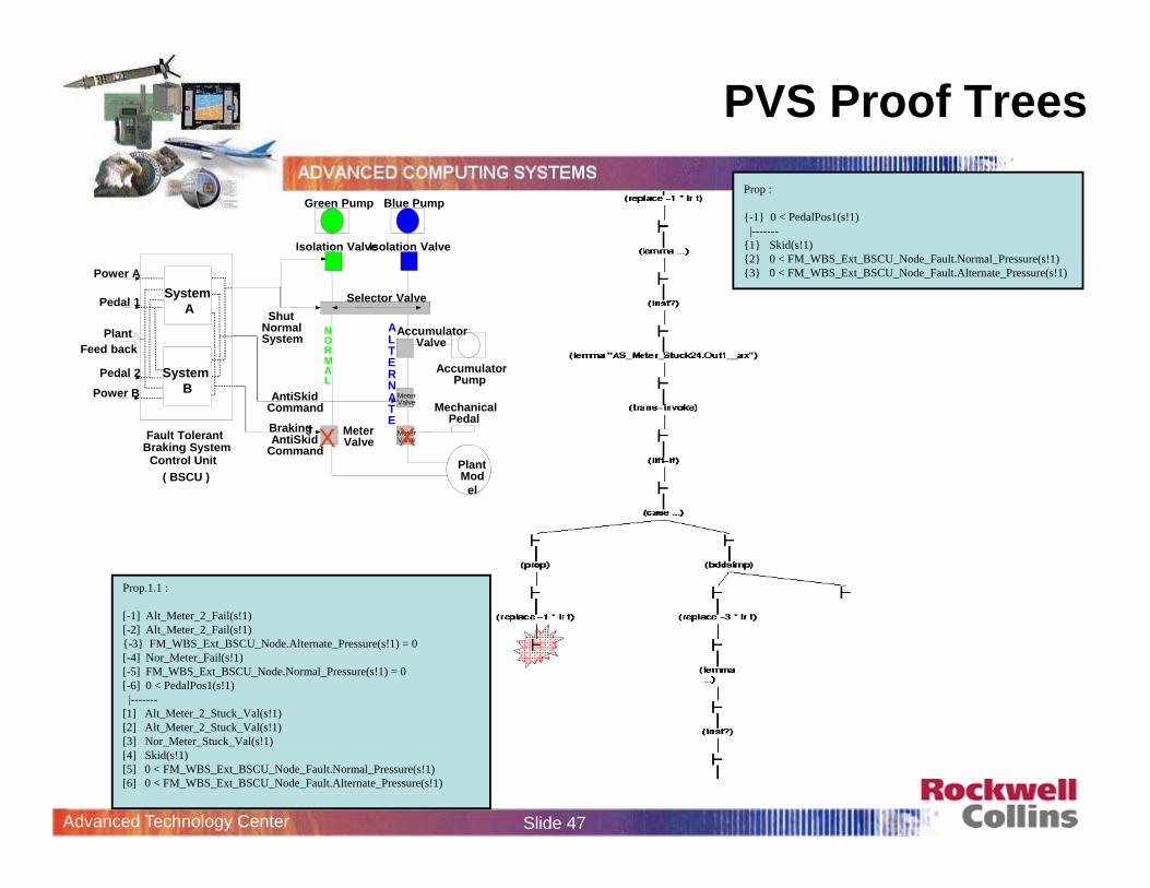
PVS Proof Trees
Prop.1.1 :
[-1] Alt_Meter_2_Fail(s!1)[-2] Alt_Meter_2_Fail(s!1){-3} FM_WBS_Ext_BSCU_Node.Alternate_Pressure(s!1) = 0[-4] Nor_Meter_Fail(s!1)[-5] FM_WBS_Ext_BSCU_Node.Normal_Pressure(s!1) = 0[-6] 0 < PedalPos1(s!1)
|-------[1] Alt_Meter_2_Stuck_Val(s!1)[2] Alt_Meter_2_Stuck_Val(s!1)[3] Nor_Meter_Stuck_Val(s!1)[4] Skid(s!1)[5] 0 < FM_WBS_Ext_BSCU_Node_Fault.Normal_Pressure(s!1)[6] 0 < FM_WBS_Ext_BSCU_Node_Fault.Alternate_Pressure(s!1)
Plant Mod
el
AntiSkid Command
Braking + AntiSkid
Command
Green Pump Blue Pump
Isolation ValveIsolation Valve
Shut Normal System
NORMAL
ALTERNATE
Accumulator Pump
Meter Valve
Meter Valve
Meter Valve
Accumulator Valve
Mechanical Pedal
Selector Valve
Power A
Pedal 1
Feed back Plant
Fault Tolerant
Control Unit ( BSCU )
Braking System
SystemA
Power BPedal 2 System
B
X X
Prop :
{-1} 0 < PedalPos1(s!1)|-------
{1} Skid(s!1){2} 0 < FM_WBS_Ext_BSCU_Node_Fault.Normal_Pressure(s!1){3} 0 < FM_WBS_Ext_BSCU_Node_Fault.Alternate_Pressure(s!1)
Advanced Technology Center Slide 48
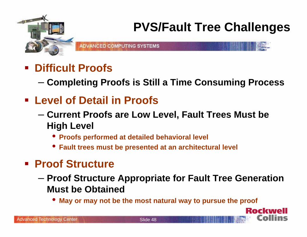
PVS/Fault Tree Challenges
Difficult Proofs– Completing Proofs is Still a Time Consuming Process
Level of Detail in Proofs– Current Proofs are Low Level, Fault Trees Must be
High Level• Proofs performed at detailed behavioral level• Fault trees must be presented at an architectural level
Proof Structure– Proof Structure Appropriate for Fault Tree Generation
Must be Obtained• May or may not be the most natural way to pursue the proof
Advanced Technology Center Slide 49
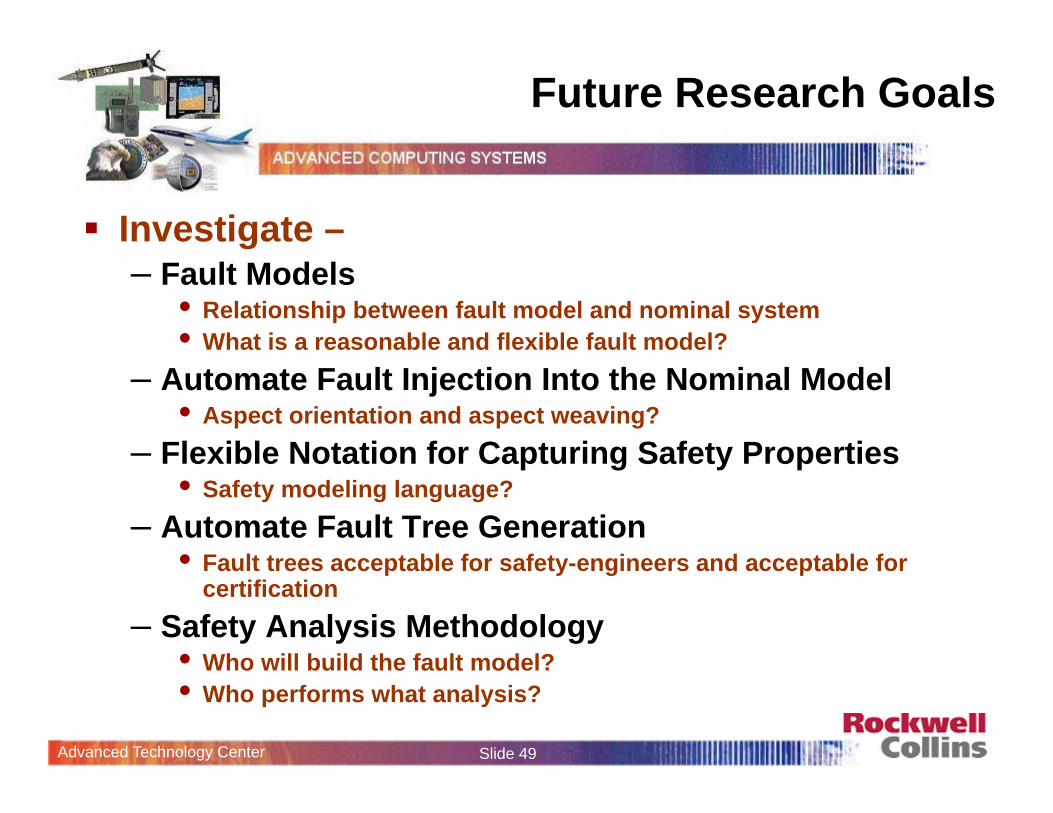
Future Research Goals
Investigate –– Fault Models
• Relationship between fault model and nominal system• What is a reasonable and flexible fault model?
– Automate Fault Injection Into the Nominal Model• Aspect orientation and aspect weaving?
– Flexible Notation for Capturing Safety Properties• Safety modeling language?
– Automate Fault Tree Generation • Fault trees acceptable for safety-engineers and acceptable for
certification– Safety Analysis Methodology
• Who will build the fault model?• Who performs what analysis?