Embed Size (px)
Citation preview

MODEL AEC 1260MODEL AEC 1260
Operating &Parts ManualOperating &Parts Manual
00022OG080410
MADE IN U
.S.A
.
MADE IN U
.S.A
.
Operating &Parts ManualOperating &Parts Manual
MODEL AEC 1260MODEL AEC 1260
®
Made in U.S.A.
Standard Features• Economical Replacement Components Including Liner• 350 Amps / 60% Duty Cycle• Wire Sizes .035 - 3/32”• Easy Field Repair• Adapter Kits Available for Most Models of Feeders
DescriptionThe Model AEC 1260 Self-Shielding Flux-Cored Gun is available with a 10’ or 15’ cable assembly with replaceable liner. The gun and cable assembly are rated at 350 amperes and 60% duty cycle, and are capable of running wire sizes .035, .045, 1/16”, .068, .072, 5/64” and 3/32”. Please consult,the parts list to order the proper components for your wire size.
The model AEC 1260 gun is set up for use with LN-7, LN-8, LN-9, LN-15® ®and LN-25 wire feeders. Adapter kits are available for Miller and Hobart
voltage sensing feeders.
The model X1260 gun is set up for use with Euro style wire feeders.
PartsBreakdown
Euro Style Direct Connect Parts Breakdown
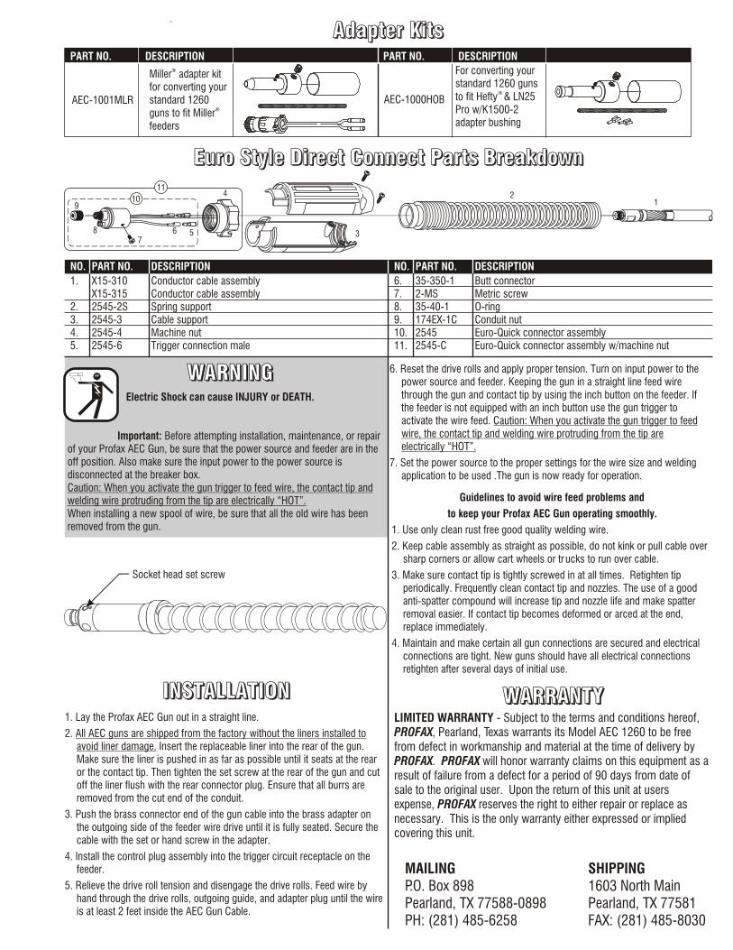
Adapter Kits
1. X15-310 Conductor cable assemblyX15-315 Conductor cable assembly
2. 2545-2S Spring support3. 2545-3 Cable support4. 2545-4 Machine nut5. 2545-6 Trigger connection male
NO. PART NO. DESCRIPTION NO. PART NO. DESCRIPTION
6. 35-350-1 Butt connector7. 2-MS Metric screw8. 35-40-1 O-ring9. 174EX-1C Conduit nut10. 2545 Euro-Quick connector assembly11. 2545-C Euro-Quick connector assembly w/machine nut
9
4
3
12
87
6 5
10
11
PartsBreakdownPartsBreakdown
Euro Style Direct Connect Parts BreakdownEuro Style Direct Connect Parts Breakdown
Adapter KitsAdapter Kits
MAILINGP.O. Box 898Pearland, TX 77588-0898PH: (281) 485-6258
SHIPPING1603 North MainPearland, TX 77581FAX: (281) 485-8030
WARNINGWARNINGWARNINGElectric Shock can cause INJURY or DEATH.
Important: Before attempting installation, maintenance, or repair of your Profax AEC Gun, be sure that the power source and feeder are in the off position. Also make sure the input power to the power source is disconnected at the breaker box.Caution: When you activate the gun trigger to feed wire, the contact tip and welding wire protruding from the tip are electrically “HOT”.When installing a new spool of wire, be sure that all the old wire has been removed from the gun.
1. Lay the Profax AEC Gun out in a straight line.
2. All AEC guns are shipped from the factory without the liners installed to avoid liner damage. Insert the replaceable liner into the rear of the gun. Make sure the liner is pushed in as far as possible until it seats at the rear or the contact tip. Then tighten the set screw at the rear of the gun and cut off the liner flush with the rear connector plug. Ensure that all burrs are removed from the cut end of the conduit.
3. Push the brass connector end of the gun cable into the brass adapter on the outgoing side of the feeder wire drive until it is fully seated. Secure the cable with the set or hand screw in the adapter.
4. Install the control plug assembly into the trigger circuit receptacle on the feeder.
5. Relieve the drive roll tension and disengage the drive rolls. Feed wire by hand through the drive rolls, outgoing guide, and adapter plug until the wire is at least 2 feet inside the AEC Gun Cable.
6. Reset the drive rolls and apply proper tension. Turn on input power to the power source and feeder. Keeping the gun in a straight line feed wire through the gun and contact tip by using the inch button on the feeder. If the feeder is not equipped with an inch button use the gun trigger to activate the wire feed. Caution: When you activate the gun trigger to feed wire, the contact tip and welding wire protruding from the tip are electrically “HOT”.
7. Set the power source to the proper settings for the wire size and welding application to be used .The gun is now ready for operation.
LIMITED WARRANTY - Subject to the terms and conditions hereof, PROFAX, Pearland, Texas warrants its Model AEC 1260 to be freefrom defect in workmanship and material at the time of delivery byPROFAX. PROFAX will honor warranty claims on this equipment as a result of failure from a defect for a period of 90 days from date of sale to the original user. Upon the return of this unit at users expense, PROFAX reserves the right to either repair or replace as necessary. This is the only warranty either expressed or implied covering this unit.
WARRANTYWARRANTYWARRANTY
Guidelines to avoid wire feed problems and
to keep your Profax AEC Gun operating smoothly.
1. Use only clean rust free good quality welding wire.
2. Keep cable assembly as straight as possible, do not kink or pull cable over sharp corners or allow cart wheels or tr ucks to run over cable.
3. Make sure contact tip is tightly screwed in at all times. Retighten tip periodically. Frequently clean contact tip and nozzles. The use of a good anti-spatter compound will increase tip and nozzle life and make spatter removal easier. If contact tip becomes deformed or arced at the end, replace immediately.
4. Maintain and make certain all gun connections are secured and electrical connections are tight. New guns should have all electrical connections retighten after several days of initial use.
INSTALLATIONINSTALLATIONINSTALLATION
Socket head set screw
AEC-1000HOB
For converting yourstandard 1260 guns
® to fit Hefty & LN25Pro w/K1500-2adapter bushing
®Miller adapter kitfor converting yourstandard 1260
®guns to fit Millerfeeders
PART NO. DESCRIPTION PART NO. DESCRIPTION
AEC-1001MLR
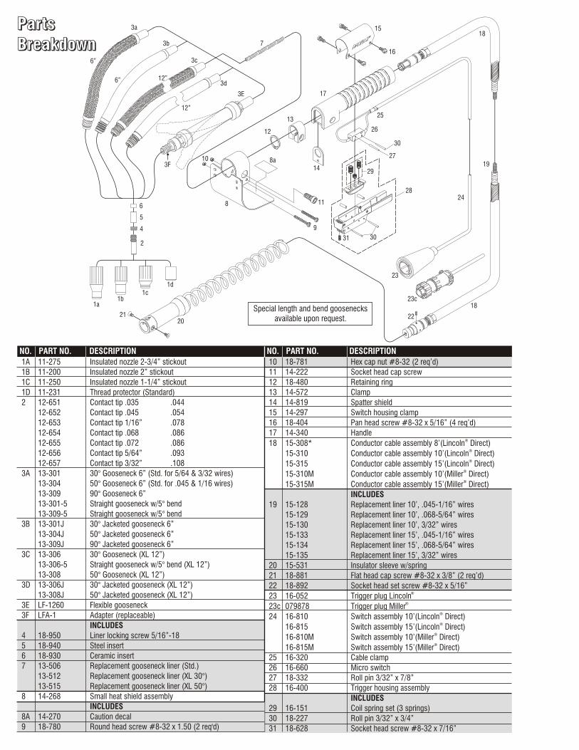
NO. PART NO. DESCRIPTION NO. PART NO. DESCRIPTION1A 11-275 Insulated nozzle 2-3/4” stickout
1B 11-200 Insulated nozzle 2” stickout
1C 11-250 Insulated nozzle 1-1/4” stickout
1D 11-231 Thread protector (Standard)
2 12-651 Contact tip .035 .044
12-652 Contact tip .045 .054
12-653 Contact tip 1/16” .078
12-654 Contact tip .068 .086
12-655 Contact tip .072 .086
12-656 Contact tip 5/64” .093
12-657 Contact tip 3/32” .108
3A 13-301 30° Gooseneck 6” (Std. for 5/64 & 3/32 wires)
13-304 50° Gooseneck 6” (Std. for .045 & 1/16 wires)
13-309 90° Gooseneck 6”
13-301-5 Straight gooseneck w/5° bend
13-309-5 Straight gooseneck w/5° bend
3B 13-301J 30° Jacketed gooseneck 6”
13-304J 50° Jacketed gooseneck 6”
13-309J 90° Jacketed gooseneck 6”
3C 13-306 30° Gooseneck (XL 12”)
13-306-5 Straight gooseneck w/5° bend (XL 12”)
13-308 50° Gooseneck (XL 12”)
3D 13-306J 30° Jacketed gooseneck (XL 12”)
13-308J 50° Jacketed gooseneck (XL 12”)
3E LF-1260 Flexible gooseneck
3F LFA-1 Adapter (replaceable)
INCLUDES
4 18-950 Liner locking screw 5/16”-18
5 18-940 Steel insert
6 18-930 Ceramic insert
7 13-506 Replacement gooseneck liner (Std.)
13-512 Replacement gooseneck liner (XL 30°)
13-515 Replacement gooseneck liner (XL 50°)
8 14-268 Small heat shield assembly
INCLUDES
8A 14-270 Caution decal
9 18-780 Round head screw #8-32 x 1.50 (2 req'd)
10 18-781 Hex cap nut #8-32 (2 req’d)
11 14-222 Socket head cap screw
12 18-480 Retaining ring
13 14-572 Clamp
14 14-819 Spatter shield
15 14-297 Switch housing clamp
16 18-404 Pan head screw #8-32 x 5/16” (4 req’d)
17 14-340 Handle®18 15-308* Conductor cable assembly 8’(Lincoln Direct)
®15-310 Conductor cable assembly 10’(Lincoln Direct)®15-315 Conductor cable assembly 15’(Lincoln Direct)
®15-310M Conductor cable assembly 10’(Miller Direct)®15-315M Conductor cable assembly 15’(Miller Direct)
INCLUDES
19 15-128 Replacement liner 10’, .045-1/16” wires
15-129 Replacement liner 10’, .068-5/64” wires
15-130 Replacement liner 10’, 3/32” wires
15-133 Replacement liner 15’, .045-1/16” wires
15-134 Replacement liner 15’, .068-5/64” wires
15-135 Replacement liner 15’, 3/32” wires
20 15-531 Insulator sleeve w/spring
21 18-881 Flat head cap screw #8-32 x 3/8” (2 req’d)
22 18-892 Socket head set screw #8-32 x 5/16”®23 16-052 Trigger plug Lincoln
®23c 079878 Trigger plug Miller®24 16-810 Switch assembly 10’(Lincoln Direct)®16-815 Switch assembly 15’(Lincoln Direct)
®16-810M Switch assembly 10’(Miller Direct)®16-815M Switch assembly 15’(Miller Direct)
25 16-320 Cable clamp
26 16-660 Micro switch
27 18-332 Roll pin 3/32” x 7/8”
28 16-400 Trigger housing assembly
INCLUDES
29 16-151 Coil spring set (3 springs)
30 18-227 Roll pin 3/32” x 3/4”
31 18-628 Socket head screw #8-32 x 7/16”
2120
1a1b
1d1c
2
4
5
6
10
3d
3E
3F
12
13
8a
8
14
11
9
29
27
30
3031
26
25
17
19
24
18
22
23
28
6” 12”
12”
23c
Special length and bend goosenecks available upon request.
3b
3a
3c
7
15
16
18
6”
PartsBreakdown
Euro Style Direct Connect Parts Breakdown
Adapter Kits
1. X15-310 Conductor cable assemblyX15-315 Conductor cable assembly
2. 2545-2S Spring support3. 2545-3 Cable support4. 2545-4 Machine nut5. 2545-6 Trigger connection male
NO. PART NO. DESCRIPTION NO. PART NO. DESCRIPTION
6. 35-350-1 Butt connector7. 2-MS Metric screw8. 35-40-1 O-ring9. 174EX-1C Conduit nut10. 2545 Euro-Quick connector assembly11. 2545-C Euro-Quick connector assembly w/machine nut
9
4
3
12
87
6 5
10
11
PartsBreakdownPartsBreakdown
Euro Style Direct Connect Parts BreakdownEuro Style Direct Connect Parts Breakdown
Adapter KitsAdapter Kits
MAILINGP.O. Box 898Pearland, TX 77588-0898PH: (281) 485-6258
SHIPPING1603 North MainPearland, TX 77581FAX: (281) 485-8030
WARNINGWARNINGWARNINGElectric Shock can cause INJURY or DEATH.
Important: Before attempting installation, maintenance, or repair of your Profax AEC Gun, be sure that the power source and feeder are in the off position. Also make sure the input power to the power source is disconnected at the breaker box.Caution: When you activate the gun trigger to feed wire, the contact tip and welding wire protruding from the tip are electrically “HOT”.When installing a new spool of wire, be sure that all the old wire has been removed from the gun.
1. Lay the Profax AEC Gun out in a straight line.
2. All AEC guns are shipped from the factory without the liners installed to avoid liner damage. Insert the replaceable liner into the rear of the gun. Make sure the liner is pushed in as far as possible until it seats at the rear or the contact tip. Then tighten the set screw at the rear of the gun and cut off the liner flush with the rear connector plug. Ensure that all burrs are removed from the cut end of the conduit.
3. Push the brass connector end of the gun cable into the brass adapter on the outgoing side of the feeder wire drive until it is fully seated. Secure the cable with the set or hand screw in the adapter.
4. Install the control plug assembly into the trigger circuit receptacle on the feeder.
5. Relieve the drive roll tension and disengage the drive rolls. Feed wire by hand through the drive rolls, outgoing guide, and adapter plug until the wire is at least 2 feet inside the AEC Gun Cable.
6. Reset the drive rolls and apply proper tension. Turn on input power to the power source and feeder. Keeping the gun in a straight line feed wire through the gun and contact tip by using the inch button on the feeder. If the feeder is not equipped with an inch button use the gun trigger to activate the wire feed. Caution: When you activate the gun trigger to feed wire, the contact tip and welding wire protruding from the tip are electrically “HOT”.
7. Set the power source to the proper settings for the wire size and welding application to be used .The gun is now ready for operation.
LIMITED WARRANTY - Subject to the terms and conditions hereof, PROFAX, Pearland, Texas warrants its Model AEC 1260 to be freefrom defect in workmanship and material at the time of delivery byPROFAX. PROFAX will honor warranty claims on this equipment as a result of failure from a defect for a period of 90 days from date of sale to the original user. Upon the return of this unit at users expense, PROFAX reserves the right to either repair or replace as necessary. This is the only warranty either expressed or implied covering this unit.
WARRANTYWARRANTYWARRANTY
Guidelines to avoid wire feed problems and
to keep your Profax AEC Gun operating smoothly.
1. Use only clean rust free good quality welding wire.
2. Keep cable assembly as straight as possible, do not kink or pull cable over sharp corners or allow cart wheels or tr ucks to run over cable.
3. Make sure contact tip is tightly screwed in at all times. Retighten tip periodically. Frequently clean contact tip and nozzles. The use of a good anti-spatter compound will increase tip and nozzle life and make spatter removal easier. If contact tip becomes deformed or arced at the end, replace immediately.
4. Maintain and make certain all gun connections are secured and electrical connections are tight. New guns should have all electrical connections retighten after several days of initial use.
INSTALLATIONINSTALLATIONINSTALLATION
Socket head set screw
AEC-1000HOB
For converting yourstandard 1260 guns
® to fit Hefty & LN25Pro w/K1500-2adapter bushing
®Miller adapter kitfor converting yourstandard 1260
®guns to fit Millerfeeders
PART NO. DESCRIPTION PART NO. DESCRIPTION
AEC-1001MLR
NO. PART NO. DESCRIPTION NO. PART NO. DESCRIPTION1A 11-275 Insulated nozzle 2-3/4” stickout
1B 11-200 Insulated nozzle 2” stickout
1C 11-250 Insulated nozzle 1-1/4” stickout
1D 11-231 Thread protector (Standard)
2 12-651 Contact tip .035 .044
12-652 Contact tip .045 .054
12-653 Contact tip 1/16” .078
12-654 Contact tip .068 .086
12-655 Contact tip .072 .086
12-656 Contact tip 5/64” .093
12-657 Contact tip 3/32” .108
3A 13-301 30° Gooseneck 6” (Std. for 5/64 & 3/32 wires)
13-304 50° Gooseneck 6” (Std. for .045 & 1/16 wires)
13-309 90° Gooseneck 6”
13-301-5 Straight gooseneck w/5° bend
13-309-5 Straight gooseneck w/5° bend
3B 13-301J 30° Jacketed gooseneck 6”
13-304J 50° Jacketed gooseneck 6”
13-309J 90° Jacketed gooseneck 6”
3C 13-306 30° Gooseneck (XL 12”)
13-306-5 Straight gooseneck w/5° bend (XL 12”)
13-308 50° Gooseneck (XL 12”)
3D 13-306J 30° Jacketed gooseneck (XL 12”)
13-308J 50° Jacketed gooseneck (XL 12”)
3E LF-1260 Flexible gooseneck
3F LFA-1 Adapter (replaceable)
INCLUDES
4 18-950 Liner locking screw 5/16”-18
5 18-940 Steel insert
6 18-930 Ceramic insert
7 13-506 Replacement gooseneck liner (Std.)
13-512 Replacement gooseneck liner (XL 30°)
13-515 Replacement gooseneck liner (XL 50°)
8 14-268 Small heat shield assembly
INCLUDES
8A 14-270 Caution decal
9 18-780 Round head screw #8-32 x 1.50 (2 req'd)
10 18-781 Hex cap nut #8-32 (2 req’d)
11 14-222 Socket head cap screw
12 18-480 Retaining ring
13 14-572 Clamp
14 14-819 Spatter shield
15 14-297 Switch housing clamp
16 18-404 Pan head screw #8-32 x 5/16” (4 req’d)
17 14-340 Handle®18 15-308* Conductor cable assembly 8’(Lincoln Direct)
®15-310 Conductor cable assembly 10’(Lincoln Direct)®15-315 Conductor cable assembly 15’(Lincoln Direct)
®15-310M Conductor cable assembly 10’(Miller Direct)®15-315M Conductor cable assembly 15’(Miller Direct)
INCLUDES
19 15-128 Replacement liner 10’, .045-1/16” wires
15-129 Replacement liner 10’, .068-5/64” wires
15-130 Replacement liner 10’, 3/32” wires
15-133 Replacement liner 15’, .045-1/16” wires
15-134 Replacement liner 15’, .068-5/64” wires
15-135 Replacement liner 15’, 3/32” wires
20 15-531 Insulator sleeve w/spring
21 18-881 Flat head cap screw #8-32 x 3/8” (2 req’d)
22 18-892 Socket head set screw #8-32 x 5/16”®23 16-052 Trigger plug Lincoln
®23c 079878 Trigger plug Miller®24 16-810 Switch assembly 10’(Lincoln Direct)®16-815 Switch assembly 15’(Lincoln Direct)
®16-810M Switch assembly 10’(Miller Direct)®16-815M Switch assembly 15’(Miller Direct)
25 16-320 Cable clamp
26 16-660 Micro switch
27 18-332 Roll pin 3/32” x 7/8”
28 16-400 Trigger housing assembly
INCLUDES
29 16-151 Coil spring set (3 springs)
30 18-227 Roll pin 3/32” x 3/4”
31 18-628 Socket head screw #8-32 x 7/16”
2120
1a1b
1d1c
2
4
5
6
10
3d
3E
3F
12
13
8a
8
14
11
9
29
27
30
3031
26
25
17
19
24
18
22
23
28
6” 12”
12”
23c
Special length and bend goosenecks available upon request.
3b
3a
3c
7
15
16
18
6”