Embed Size (px)
Citation preview

Model a House
1
Tutorial: House
Topics Covered in this Tutorial
Work area
¸
Snap
¸
Grid
¸
Layers
¸
Edit Objects
¸
View
¸
Select Mask
¸
Preferences
Modeling
¸
Line
¸
Arcs
¸
Rectangle
¸
Text
¸
Hatch
¸
Primitives
¸
Extruded solid
¸
Thicken solid
¸
Surfaces
Editing
¸
Move
¸
Rotate
¸
Offset
¸
Array
¸
Remove section from solid
¸
Boolean operations
¸
Shell solid
¸
Model to Sheet
¸
Section cut
¸
Drawing views
… and more.

Model a House
2
In this tutorial we will construct a house starting with 3D modeling and finishing with 2D illustrations or layouts.
Setting up the Drawing
1. Most newer computers will not have CPU speed problems so go to
File>Pref-erences>Display.
In the Object Type pull down menu, set the Resolution for Curve, Surface and Solid to
Super Fine
.
2. In the
Preferences
menu select
Grid,
set the Spacing values to
1
m
, Sub-spac-ing to
1
and the
Grid size to
30
by
10
.
3. Also, if you don’t already have it open, show the Snap Option palette (
Window>Snaps
). Check the
To Grid
option.
Note: units used in this tutorial are meters.

Model a House
3
Walls
1. In the Layer Manager, change the name of Layer 1 to
curves
.
2. Starting at the
Origin,
reproduce the series of
Connected Lines
shown below. The overall size of the building is 20 meters by 13 meters.
3. Switch to the Isometric View (
“f”
).

Model a House
4
4. Select the Solid Extrude tool, using the by Thin Extrude option in the Message Line. The extrude Distance is
3m
with an
Offset
of
.3m
.
5. Switch back to the Top View (
“d”
).
6. Now using the
snap
points indicated below, create lines for the internal parti-tion walls.

Model a House
5
7. To create the arc, select the
Tangent Arc
tool. Locate the arc using
the snap
points shown below.
8. Switch back to the
Isometric view
(
“f”
).
9. Select the Solid Extrude tool. Using the
Thin Extrude
option in the Message Line, extrude all of the internal walls by
3m
and an
Offset
of
.1m
.
When using the
Thin Extrude
tool, the alignment of the extruded solid can be changed by tapping the Ctrl (PC) or the Option (Mac) key. There are three align-ment points for the solid to the wireframe geometry: Centered, Inside & Outside.

Model a House
6
10. In the Layer Manager, create a new layer, rename the layer to
walls.
11. Place all of the walls onto the
wall
layer.
Right Mouse
click in the white-space of your drawing, choose
Select All>Solids
. This operation will select
only
the solids in the drawing. Show the Edit Objects dialog box
(Ctrl + i or Command + i),
under the Attributes Tab, choose
walls
in the
Layer
drop down menu.
Save your work.
Creating the Windows
1. Create a
new layer
, rename it to
windows
, make it current and turn off the visi-bility of the other layers.
2. Switch to the Front View (
“s”
).
3. Draw a
Rectangle
starting at the
Origin
, with a
Width
of
1.2
m
and a
Height
of
1.4
m
.
4.
Offset
the rectangle to its inside by
0.05
.
5. Switch to the Isometric View (
“f”
).

Model a House
7
6.
Extrude
all these objects using the
Mid-plane
option in the Message Line. The
Distance
is
0.1.
7. Create a second Midplane Extrusion using the internal rectangle, the Distance is .05.
8. Move a copy of the external rectangle by 0.3m in negative y direction (hold down the Ctrl [PC] or Option [Mac] key).
9. Move all of the window objects to this location dX = 1.9; dY = 0.125; dZ = 1.
10. Turn on the walls layer.
11. Show Grid and check the To Grid option in Snaps palette.
12. Copy this set of elements following the scheme illustrated in the picture below.
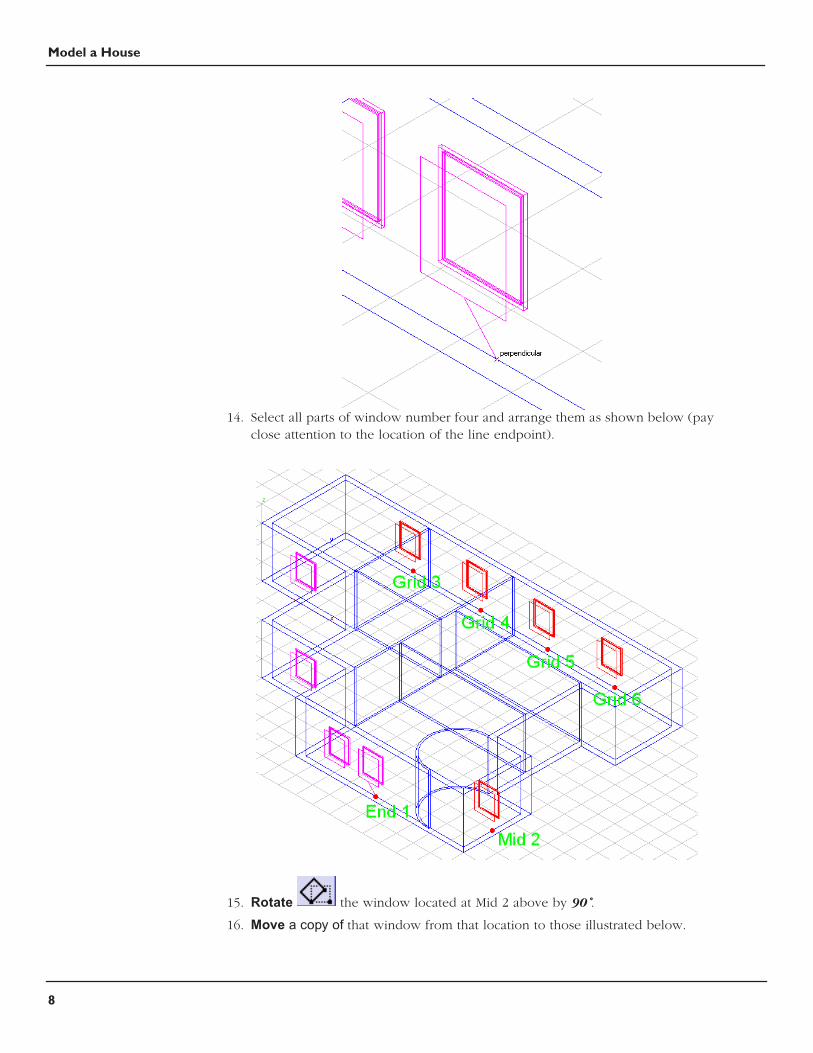
13. We need a location marker for placing the next set of windows, so draw a Line
from the Midpoint of the rectangle on window number four (Grid point 4) perpendicular to the internal profile of the wall.
Model a House
8
14. Select all parts of window number four and arrange them as shown below (pay close attention to the location of the line endpoint).
15. Rotate the window located at Mid 2 above by 90˚.
16. Move a copy of that window from that location to those illustrated below.

Model a House
9
Save your work.
Doors
We will use the same method to create the doors that we used to create the win-dows with one slight variation. This variation has a huge time saving potential if you begin to incorporate it into your workflow.
1. Create a new layer, name it doors.
2. Switch to the Front View ( “s”).
3. Draw a Rectangle from the Origin with a Width of 1 and a Height of 2.1.
4. Offset the rectangle to the inside by 0.05m.
5. Draw a selection fence around bottom line of the internal rectangle and extend
it to the bottom line of the external rectangle. Use the selection tool to move the lines together.

Model a House
10
6. Switch to the Isometric View ( “f”).
7. Extrude the external rectangle by 0.1m. Repeat the extrude on the internal rectangle (use the same extrusion distance).
8. Subtract the second extrude from the first.
9. Extrude the internal rectangle again, this time with a distance of 0.05m
10. Change the work plane to Global in the Planes Menu.
11. Rotate it from lower left corner by -90˚.
12. Move a copy (Ctrl [PC] or Option [Mac]) of the door to the location shown in the picture. Also create the lines shown in red as a reference for locating copies of the door.

Model a House
11
13. Select the door and choose the Linear Duplicate tool. Set the Column value to 6 and its distance to 2. Leave the Row value set to 1. Make sure the offset spacing is set to Step Offset. The most important thing is to have the Associative duplicates option checked.
14. Arrange the copied doors with a series of moving and rotating operations as illustrated in the figures below.

Model a House
12

Model a House
13
Window and Door Cutouts
Here are some simple operations producing holes in our walls that accommodate the windows and doors.
Windows.
1. Choose the Remove section from solid tool. Select the exterior wall solid, next select one of the window rectangles that we moved .3m in the neg-ative y direction, the last step is to specify the two points that the rectangle will use to cut through the wall. Repeat operation for all of the windows.
Note: You can select multiple cutout rectangles at one time, the only requirement is that the rectangles exist in the same plane.

Model a House
14
Doors.
1. Use the Trim solid tool. Select the door frame as the trimming boundary and then select the wall as the object to trim.

Model a House
15
Finishing Details
Now we will add some finishing elements to our model.
1. Draw a Cylinder using the 1 point creation method, place center of the cylinder at the following location, X = 0.15; Y = -7.85; Z = 0; Height of 3; Diameter of 0.3. Create it in the walls layer.
2. Create a Block primitive using the 1 point creation method. This point is located at the Quadrant on the base of our curved partition wall. The values of the block are: L & W = 2; H = 2.1.
3. Subtract this solid from the wall.
4. Create another Block, this time use the 3 point creation method. Specify the points located at Mid 1 and Grid 2 of picture, the height of the block is 2.1m.
5. Subtract this block from the wall. Create a third block representing the front door. The Length is 0.1m, the Width is 1.50m and the Height is 2.1m.

Model a House
16
6. Switch to the Top View ( “d”).
7. To create the roof of the building, draw a Rectangle that is 1 meter
large than the entire house. Extrude the rectangle by 2m adding a Draft
Angle of -45˚. Move the solid in positive z direction 3 meters.
Save your file.
Creating your own Model to Sheet Layouts
The following steps illustrate how to create your own Layouts. These steps are not always necessary because Ashlar’s programs come with an assortment of pre-defined layouts.
1. Open a new file ( Ctrl + n or Command +n) or Menu File > New.
2. Draw a Rectangle with lower left corner point at X = 1; Y = 1, the Width is 57.40cm (we have switched Units to centimeters) and the Height is 40cm.
3. Offset the rectangle to the inside by 1 cm. Draw a selection fence around the bottom offset line, move it in the positive y axis 5 cm.

Model a House
17
4. Using the Line tool, create one horizontal and one vertical line located at the Midpoint of the existing lines.
The next few step are critical in this process.
5. Go to Window>Sheet tools.
6. Select the Drawing view tool. Create four views that are aligned with each of the squares we drew.
7. Click on upper left view to activate it, then right-click and choose Properties. Change the name to Top, the scale to 1 and the Visible Pen style to Use Object color. Click Apply and then OK. Right-click again, this time choose Change view, change the view to Top from the drop down menu.

Model a House
18
8. Repeat operation for the remaining views.
Save this file in the folder called Layouts. You can find this folder on your hard disk as a sub-folder of the Cobalt installation. Use the name House_layout.co.
9. Return to the file where you modeled the house.
10. While in Top view, make all layers visible except curves, select all and choose
the Model to Sheet tool. (Make sure that all of the lines, arcs, etc. are on the curves layer. Right-Mouse-Click and choose Select All > Curves, open the Edit Objects dialog box and assign them to that layer.)

Model a House
19
Select all of the solids (this should be the only items visible), choose House_layout.co from the Layouts drop down menu, set the scale to 0.01 and choose ignore for all pen styles but Visible, set this to Use Object Color.
Now, let’s modify our Model To Sheet drawing by deleting one view and adding a plan view.
11. Click on the Top view to select it, Right Click in the Top view to show the drop down menu, choose Delete.
12. Click on Front view to make it active.
13. Select the Section cut through view tool (It requires that a drawing view be selected before the tool will work). Choose the Horizontal section create mode from the Message Line. Choose the Midpoint of a wall for the cut through view, move the mouse up to place this new view where the Top view used to be.

Model a House
20
14. Hatch is automatically generated for section views (unless you uncheck this option in Properties window of the view). The scale for the Hatch is too big, select the hatch and in the Edit Objects window set the scale to 0.04.
Now we have arrived at our goal. Objects in these view are linked to the 3D model and consequently any change to the model will be reflected directly on the sheet.

Model a House
21
We are going to take advantage of this linking by modifying the door we used to create the Linear duplicates.
1. Turn off all layers except walls and doors. We have decided that the doors need to be modified to create a more realistic look. Find the door used to create the Linear duplicates.
2. Draw one Circle with a Diameter of 7 and a Cube (it doesn’t matter what size the cube is) as shown in the picture below.
3. Cutout the circle profile from the door and Subtract the Cube from the door, all the doors are updated in the model and in the sheet, at the same time.
This completes the tutorial, save your work.

Model a House
22


![Indigenous Tutorial Assistance Scheme [ITAS] · Indigenous Tutorial Assistance Scheme [ITAS] Tutor Guide July 2013 page 3 Table of Contents JUMBUNNA INDIGENOUS HOUSE OF LEARNING (IHL)](https://img.pdfslide.us/doc/110x75/5ae0568d7f8b9afd1a8dd115/indigenous-tutorial-assistance-scheme-itas-tutorial-assistance-scheme-itas-tutor.jpg)