Embed Size (px)
Citation preview

Model 9437-500Low Level Dissolved OxygenMonitoring System
Operating Instructions
4600ABB
D.O.9.8
A1
A2
4600ABB
D.O. (mg/kg)
9.8
A1
A2
Dissolved Oxygen 9437

ABB AUTOMATION
The Company
ABB Automation is an established world force in the design and manufacture ofinstrumentation for industrial process control, flow measurement, gas and liquid analysis andenvironmental applications.
As a part of ABB, a world leader in process automation technology, we offer customersapplication expertise, service and support worldwide.
We are committed to teamwork, high quality manufacturing, advanced technology andunrivalled service and support.
The quality, accuracy and performance of the Company’s products result from over 100 yearsexperience, combined with a continuous program of innovative design and development toincorporate the latest technology.
The NAMAS Calibration Laboratory No. 0255 is just one of the ten flow calibration plantsoperated by the Company, and is indicative of ABB Automation’s dedication to qualityand accuracy.
Use of Instructions
Warning.An instruction that draws attention to the risk of injury ordeath.
Caution.An instruction that draws attention to the risk of damage tothe product, process or surroundings.
Note.Clarification of an instruction or additional information.
Information.Further reference for more detailed information ortechnical details.
Although Warning hazards are related to personal injury, and Caution hazards are associated with equipment or property damage,it must be understood that operation of damaged equipment could, under certain operational conditions, result in degradedprocess system performance leading to personal injury or death. Therefore, comply fully with all Warning and Caution notices.
Information in this manual is intended only to assist our customers in the efficient operation of our equipment. Use of this manualfor any other purpose is specifically prohibited and its contents are not to be reproduced in full or part without prior approval ofMarketing Communications Department, ABB Automation.
Health and SafetyTo ensure that our products are safe and without risk to health, the following points must be noted:
1. The relevant sections of these instructions must be read carefully before proceeding.
2. Warning labels on containers and packages must be observed.
3. Installation, operation, maintenance and servicing must only be carried out by suitably trained personnel and in accordance with theinformation given.
4. Normal safety precautions must be taken to avoid the possibility of an accident occurring when operating in conditions of high pressureand/or temperature.
5. Chemicals must be stored away from heat, protected from temperature extremes and powders kept dry. Normal safe handling proceduresmust be used.
6. When disposing of chemicals ensure that no two chemicals are mixed.
Safety advice concerning the use of the equipment described in this manual or any relevant hazard data sheets (where applicable) may beobtained from the Company address on the back cover, together with servicing and spares information.
BS EN ISO 9001
Cert. No. Q5907
REGISTERE
D
EN 29001 (ISO 9001)
Lenno, Italy – Cert. No. 9/90A
0255
Stonehouse, U.K.

1
1 INTRODUCTION .......................................................... 2
2 MECHANICAL INSTALLATION .................................. 32.1 Siting Requirements .......................................... 3
2.1.1 Instruments .......................................... 32.1.2 Dissolved Oxygen Flowcell ................. 3
2.2 Mounting the Instrument ................................... 32.2.1 Wall-mounted Instrument .................... 32.2.2 Panel-mounted Instrument .................. 4
2.3 Installing the Dissolved Oxygen Flowcell ......... 52.3.1 Flowcell Dimensions (Overall) ............. 52.3.2 Enclosure Dimensions (Optional) ........ 52.3.3 Connecting the Sample Lines ............. 5
3 ELECTRICAL CONNECTIONS ................................... 63.1 Access to Terminals .......................................... 6
3.1.1 Wall-mounted Instruments ................... 63.1.2 Panel-mounted Instruments ................ 6
3.2 Connections, General ....................................... 73.2.1 Relay Contact Protection
and Interference Suppression ............. 73.3 Wall-mounted Instrument Connections ............. 83.4 Panel-mounted Instrument Connections .......... 93.5 Selecting the Mains Voltage ............................ 10
3.5.1 Wall-mounted Instrument .................. 103.5.2 Panel-mounted Instrument ................ 10
4 SETTING UP .............................................................. 114.1 Fitting the Dissolved Oxygen Sensor .............. 114.2 Connecting the Flowcell .................................. 124.3 Checking Sample Flow ................................... 12
5 CONTROLS AND DISPLAYS .................................... 135.1 Displays ........................................................... 135.2 Switch Familiarization ..................................... 13
6 START UP AND OPERATION ................................... 146.1 Instrument Start-up ......................................... 156.2 Operation – Dissolved Oxygen
Measurement Mode ........................................ 156.2.1 Operation Page ................................. 156.2.2 Calibration Page ................................ 16
7 PROGRAMMING AND ELECTRICALCALIBRATION ........................................................... 177.1 Access to Secure Parameters ........................ 177.2 Select Language Page .................................... 177.3 Set Up Parameters Page ................................ 177.4 Set Up Outputs Page ...................................... 187.5 Electrical Calibration ....................................... 20
7.5.1 Equipment Required .......................... 207.6 Preparation ...................................................... 207.7 Electrical Calibration Page .............................. 20
8 MAINTENANCE ......................................................... 228.1 Maintenance .................................................... 22
8.1.1 Changing the Sensor ......................... 228.2 Error Messages ............................................... 22
9 SIMPLE FAULT FINDING .......................................... 239.1 Low Sensor Output or no Response
to D.O. Changes ............................................. 239.2 Checking the Temperature Input ..................... 239.3 High Sample Readings ................................... 23
10 SPECIFICATION ........................................................ 24
11 SPARES ..................................................................... 2611.1 Strategic Spares .............................................. 26
CONTENTS

2
1 INTRODUCTION
This manual describes how to install and operate the 9437Low Level Dissolved Oxygen Monitoring system. Fig. 1.1shows the main elements of the system.
The Dissolved Oxygen (D.O.) transmitters and associatedflowcell have been designed for continuous monitoring andcontrol of power station boiler feed water/steam condensate.
System status can be assessed remotely using programmablealarm and/or current output diagnostic functions.
The 9437 500 transmitter is a wall-mounted instrument and the9437 501 model is a panel-mounted, 1/4 DIN-sized instrument.Both instruments have a single programmable D.O. inputchannel, and a single temperature input channel. The sampletemperature is sensed by a Pt1000 resistance thermometerincorporated in the flowcell.
Instrument operation and programming is via four tactilemembrane switches located on the front panel. Programs areprotected from unauthorized alteration by a five-digit securitycode.
Model 9437Panel-Mounted Transmitter
Dissolved Oxygen 9437
Sensor mounted inoptional enclosure
Model 9437Wall-Mounted Transmitter
4600ABB
4600ABB
D.O. µg/kg18 . 1
A1
A2
Fig. 1.1 System Elements
3
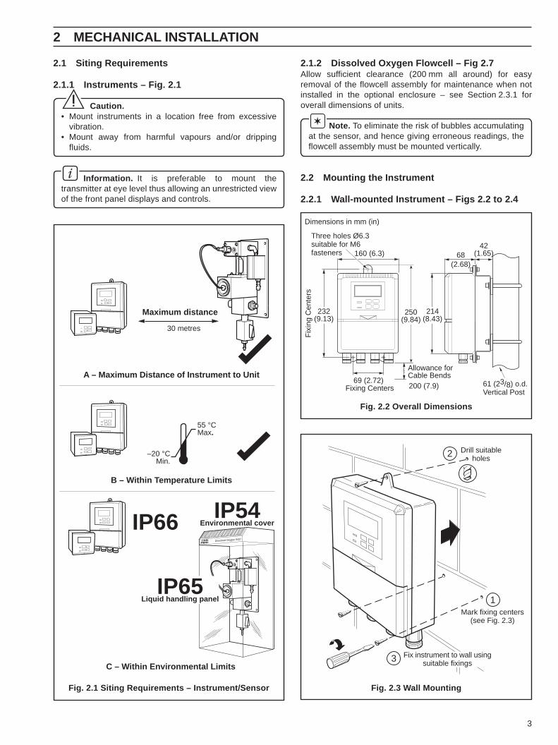
2.1 Siting Requirements
2.1.1 Instruments – Fig. 2.1
Caution.• Mount instruments in a location free from excessive
vibration.• Mount away from harmful vapours and/or dripping
fluids.
Information. It is preferable to mount thetransmitter at eye level thus allowing an unrestricted viewof the front panel displays and controls.
Fig. 2.1 Siting Requirements – Instrument/Sensor
Fig. 2.2 Overall Dimensions
Maximum distance
30 metres
C – Within Environmental Limits
55 °CMax.
–20 °CMin.
B – Within Temperature Limits
A – Maximum Distance of Instrument to Unit
IP66 IP54Environmental cover
Dissolved Oxygen 9437
IP65Liquid handling panel
68(2.68)
42(1.65)
Fix
ing
Cen
ters
160 (6.3)
69 (2.72)Fixing Centers
Allowance forCable Bends200 (7.9) 61 (23/8) o.d.
Vertical Post
214(8.43)
232(9.13)
Three holes Ø6.3suitable for M6fasteners
Dimensions in mm (in)
250(9.84)
Mark fixing centers(see Fig. 2.3)
Drill suitableholes
Fix instrument to wall usingsuitable fixings
1
2
3
2 MECHANICAL INSTALLATION
2.1.2 Dissolved Oxygen Flowcell – Fig 2.7Allow sufficient clearance (200 mm all around) for easyremoval of the flowcell assembly for maintenance when notinstalled in the optional enclosure – see Section 2.3.1 foroverall dimensions of units.
Note. To eliminate the risk of bubbles accumulatingat the sensor, and hence giving erroneous readings, theflowcell assembly must be mounted vertically.
2.2 Mounting the Instrument
2.2.1 Wall-mounted Instrument – Figs 2.2 to 2.4
Fig. 2.3 Wall Mounting

4
…2.2.1 Wall-mounted Instrument – Fig 2.4 2.2.2 Panel-mounted Instrument – Figs 2.5 and 2.6
Fig. 2.4 Pipe Mounting Fig. 2.5 Overall Dimensions
Fig. 2.6 Panel Mounting
…2 MECHANICAL INSTALLATION
Position ‘U’ bolts on pipe
Position plates over ‘U’ bolts
Secure transmitter to mounting plate
Secure plates
1
2
3
4
191 (7.52)12 (0.47)
Panel Cut-out
96 (3.78)
96(3.78)
+0.8–092
(3.62 )+0.03–0
+0.8–092 (3.62 )+0.03
–0
Dimensions in mm (in)
Cut a hole in the panel (see Fig. 2.5 for dimensions).Instruments may be close stacked to DIN 43835.
Insert the instrument into thepanel cut-out.
Refit the panel clamps to the case, ensuringthat the panel clamp anchors are locatedcorrectly in their slot.
Secure the instrument bytightening the panel clampretaining screws.
Loosen the retaining screwon each panel clamp.
Remove the panel clamp andanchors from the instrument case.
4
5
6
1
3
2 3

5
2.3 Installing the Dissolved Oxygen Flowcell
2.3.1 Flowcell Dimensions (Overall) – Fig. 2.7
2.3.3 Connecting the Sample Lines – Fig. 2.9Mount the flowcell vertically (with or without the enclosure) asshown in Figs 2.7 and 2.8. Connect the sample inlet and outlettubes as shown in Fig. 2.9.
Note.• The sample flowrate must be between 100 and
400 ml min–1.• The Company recommends that stainless steel tubing
is used for sample inlet lines.• All sample drains should be kept as short as possible
and be vertical to allow the sample to drain freely.
Fig. 2.7 Flowcell Dimensions
2.3.2 Enclosure Dimensions (Optional) – Fig. 2.8
Fig. 2.8 Enclosure Dimensions
Note. Drain tubes must be straight andvertical to allow the sample to flow freely.
100
85
175
190
116approximately
310
142approximately
Ø 5.5for M5 fastener infour positions
Dimensions in mm.
Dissolved Oxygen 9437
Ø 8.5for M8 fastener infour positions
Dimensions in mm.
25 25
25
160 mm space required below sensorpanel, to allow for the opening of the
optional environmental cover.
160
440
200
325
Secure the enclosure to avertical surface using the fourfixing holes and suitablescrews/bolts.
Flow Gauge(ml/min)
NeedleValve
(to set flowrate)
SampleOutlet
BallValve
SampleDrain
User supplied10 mm i.d.
flexible plastictubing
User supplied10 mm i.d.
flexible plastictubing
1 m maximum
Drain
SampleOutlet
Sample inlet viashut off valve ifrequired.
Sample drain duringautomatic calibration
2 MECHANICAL INSTALLATION
Fig. 2.9 Connecting the Sample Lines

6
3 ELECTRICAL CONNECTIONS
Fig. 3.1 Access to Terminals –Wall-mounted Instrument
Fig. 3.2 Access to Terminals – Panel-mountedInstrument (Rear View)
Warning.• Before making any connections, ensure that the power supply, any high voltage-operated control circuits and high common
mode voltage are switched off.• Although certain instruments are fitted with internal fuse protection, a suitably rated external protection device, e.g. fuse or
miniature circuit breaker (m.c.b.), must also be fitted by the installer.
3.1 Access to Terminals
3.1.1 Wall-mounted Instruments – Fig. 3.1 3.1.2 Panel-mounted Instruments – Fig. 3.2
1
2
3
4
2
Earth Studs
slidedown
Pull outslightly. . . . . . and
slide off
Removeprotectioncover
Slackencaptivescrews
Remove nuts andprotection cover
Removemains cover
MainsCover
Earth Stud
1
2

7
3.2 Connections, General
Information.• Earthing (grounding) – stud terminals are fitted to the transmitter case for bus-bar earth (ground) connection – see
Fig. 3.1 or 3.2.
• Cable lengths – The cable length between the flowcell and the electronics unit is provided as ordered, and suitablyterminated at both ends.
• Cable routing – always route the signal cable and mains-carrying/relay cables separately, ideally in earthed metal conduit.
Ensure that the cables enter the transmitter through the glands nearest the appropriate screw terminals and are short anddirect. Do not tuck excess cable into the terminal compartment.
• Cable glands & conduit fittings – ensure a moisture-tight fit when using cable glands, conduit fittings and blanking plugs/bungs (M20 holes). The M16 glands ready-fitted to wall-mounted instruments accept cable of between 4 and 7 mmdiameter.
• Alarm Relay –the relay contacts are voltage-free and must be appropriately connected in series with the power supply andthe alarm/control device which they are to actuate. Ensure that the contact rating is not exceeded. Refer also toSection 3.2.1 for relay contact protection details when the relays are to be used for switching loads.
• Retransmission output – Do not exceed the maximum load specification for the selected current retransmission range –see Section 7.
Since the retransmission output is isolated the –ve terminal must be connected to earth (ground) if connecting to theisolated input of another device.
3.2.1 Relay Contact Protection and Interference Suppression – Fig. 3.3If the relays are used to switch loads on and off, the relay contacts can become eroded due to arcing. Arcing also generates radiofrequency interference (RFI) which can result in instrument malfunction and incorrect readings. To minimize the effects of RFI, arcsuppression components are required; resistor/capacitor networks for a.c. applications or diodes for d.c. applications. Thesecomponents can be connected either across the load or directly across the relay contacts. On 4600 Series instruments the RFIcomponents must be fitted to the relay terminal block along with the supply and load wires – see Fig. 3.3.
For a.c. applications the value of the resistor/capacitor network depends on the load current and inductance that is switched.Initially, fit a 100R/0.022 µF RC suppressor unit (part no. B9303) as shown in Fig. 3.3A. If the instrument malfunctions (incorrectreadings) or resets (display shows 88888) the value of the RC network is too low for suppression – an alternative value must beused. If the correct value cannot be obtained, contact the manufacturer of the switched device for details on the RC unit required.
For d.c. applications fit a diode as shown in Fig. 3.3B. For general applications use an IN5406 type ( 600 V peak inverse voltageat 3 A – part no. B7363)
Note. For reliable switching the minimum voltage must be greater than 12 V and the minimum current greater than100 mA.
NC C NO
ExternalD.C. Supply
+ –
Relay Contacts
Load
Diode
NC C NO
ExternalA.C. Supply
L N
Relay Contacts
CR
Load
A – A.C. Applications B – D.C. Applications
3 ELECTRICAL CONNECTIONS…
Fig. 3.3 Relay Contact Protection
8
…3 ELECTRICAL CONNECTIONS
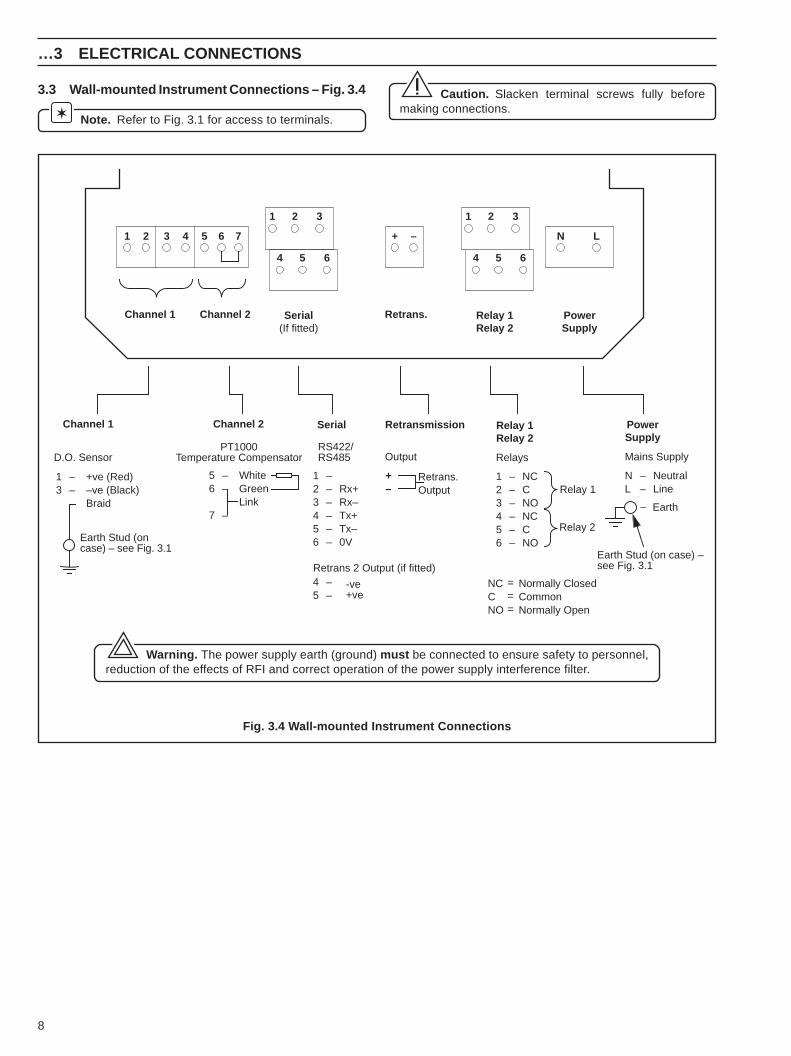
3.3 Wall-mounted Instrument Connections – Fig. 3.4
Note. Refer to Fig. 3.1 for access to terminals.
Caution. Slacken terminal screws fully beforemaking connections.
Warning. The power supply earth (ground) must be connected to ensure safety to personnel,reduction of the effects of RFI and correct operation of the power supply interference filter.
Fig. 3.4 Wall-mounted Instrument Connections
PowerSupply
Retransmission Relay 1Relay 2
Serial
PowerSupply
Retrans. Relay 1Relay 2
1 2 3 4 5 6 7 + – N L
Serial(If fitted)
1 2 3
4 5 6
1 2 3
4 5 6
123456
45
––––––
––
Rx+Rx–Tx+Tx–0V
Retrans.Output
Relays
123456
––––––
NCCNONCCNO
Relay 1
Mains Supply
NL
––
NeutralLine
– Earth
OutputRS422/RS485
Earth Stud (on case) –see Fig. 3.1
NCCNO
Normally ClosedCommonNormally Open
===
Channel 2Channel 1
13
––
+ve (Red)–ve (Black)Braid
D.O. Sensor
Earth Stud (oncase) – see Fig. 3.1
Channel 2Channel 1
PT1000Temperature Compensator
56
7
––
–
WhiteGreenLink
+–
Retrans 2 Output (if fitted)
-ve+ve
Relay 2

9
3 ELECTRICAL CONNECTIONS…
3.4 Panel-mounted Instrument Connections – Fig. 3.5
Note. Refer to Fig. 3.2 for Access to Terminals.
Caution. Slacken terminal screws fully before making connections.
Warning. The power supply earth (ground) must be connected to ensure safety to personnel,reduction of the effects of RFI and correct operation of the power supply interference filter.
+–
Normally ClosedCommon
Normally OpenNormally Closed
CommonNormally Open
NeutralLive
Earth
TBA
Relay 1
Relay 2
123456789ENL
1 2 3 4 5 6 7 8
1012
Mains Supply
RetransmissionOutput
0VRx–Rx+Tx–Tx+LinkGreenWhite
–ve (Black)
+ve (Red)
TBB
RS422/RS485Serial Interface(if fitted)
D.O. Sensor
123456789ENL
1 2 3 4 5 6 7 8 9101112
Earth Stud
Earth Stud (on case)
Earth Stud (on case)
Pt1000Temperaturecompensator
Braid
Retrans 2Output (if fitted)
–ve+ve
45
Fig. 3.5 Panel-mounted Instrument Connections
10
…3 ELECTRICAL CONNECTIONS
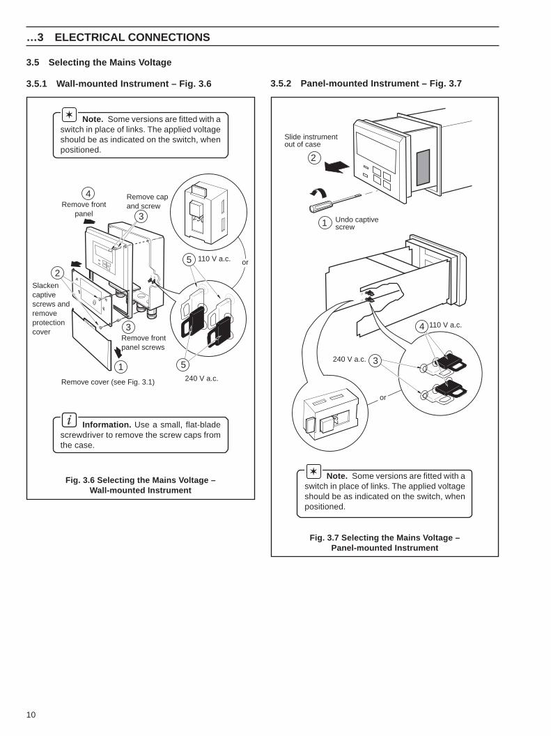
3.5 Selecting the Mains Voltage
3.5.1 Wall-mounted Instrument – Fig. 3.6
Note. Some versions are fitted with aswitch in place of links. The applied voltageshould be as indicated on the switch, whenpositioned.
Information. Use a small, flat-bladescrewdriver to remove the screw caps fromthe case.
Fig. 3.7 Selecting the Mains Voltage –Panel-mounted Instrument
Note. Some versions are fitted with aswitch in place of links. The applied voltageshould be as indicated on the switch, whenpositioned.
3.5.2 Panel-mounted Instrument – Fig. 3.7
Remove cover (see Fig. 3.1)
Remove frontpanel screws
Remove frontpanel
Remove capand screw
Slackencaptivescrews andremoveprotectioncover
240 V a.c.
110 V a.c.
230
or
1
3
4
3
5
2
5
Undo captivescrew
Slide instrumentout of case
240 V a.c.
110 V a.c.
230
or
3
4
1
2
Fig. 3.6 Selecting the Mains Voltage –Wall-mounted Instrument

11
4 SETTING UP
Caution.• Only install the oxygen sensor immediately prior to use, otherwise leave
it stored in its protective container.
• Take special care to line up the two pins in the oxygen sensor with theirrespective sockets before making the connection and tightening.
• Take care not to damage the delicate membrane on the end of theoxygen sensor.
• Ensure that the mating surfaces (carrying the electrical connection) ofthe oxygen sensor and connector body are clean and completely dry.
1
2
3
4
57
Optional enclosure not shown for clarity
Slip the connector nut overthe connector body andscrew on to the oxygensensor firmly.
Insert the complete assemblyinto the flowcell ensuring thatthe O-ring is in place.
Remove the top from the oxygen sensorcontainer.
Unscrew the protective cap from the rear ofthe oxygen sensor
Use the clamping screw to secure theassembly. Screw in firmly using fingerpressure only.
Slide the thrust washer overthe connector body.
Place an O-ring (provided) as shown andlocate the connector bodyon the oxygen sensor.
Flowcell
O-ring
OxygenSensor
ConnectorBody
O-ring
ClampingScrew
ThrustWasher
ConnectorNut
6
Caution. Do not overtighten the clamping screw.
Fig. 4.1 Fitting the Dissolved Oxygen Sensor
4.1 Fitting the Dissolved Oxygen Sensor – Fig. 4.1

12
…4 SETTING UP
4.2 Connecting the Flowcell – Fig. 4.2
Note.• The plug is a latching type to prevent it's
accidental removal. To remove, hold theplug at its widest point and pull out.
• The plug is protected against spillage andcorrosion by a sleeve which slides over it.
4.3 Checking Sample Flow – Fig. 4.3Check that the sample flows correctly in bothnormal operation and during a calibration orthermal overload.To simulate a calibration manually, open thevalve – see Section 6.2.1 Operating Page.After approximately 30 seconds carefullyremove the dissolved oxygen sensor andcheck that the flowcell is empty. If sample stillflows, check that the installation complies withSection 2.3.3.
Line up the red spots andpush the plug on firmly untilthe locking ring engages.
Push the sensor connector onfirmly and tighten ONE TURNclockwise.
Flow duringnormal operation
Ball Valve – Closed
FlowRegulatingValve
Sensor
Flow Indicator
Drain
SampleIn
Flow during calibration orthermal overload condition
Ball Valve – Open
SampleIn
Drain
Fig. 4.2 Electrical Connections at the Flowcell
Fig. 4.3 Sample Flow Schematic

13
5 CONTROLS AND DISPLAYS
Fig. 5.2 Membrane Switch Functions
1 8 . 1D.O. µg/kg
AlarmL.E.D's
UpperDisplay Line
LowerDisplay Line
Membrane Switches
Fig. 5.1 Location of Controls and Displays
A – Advancing to Next Page
Parameter 1Parameter 2Parameter 3Parameter 4
Page 1Parameter 1Parameter 2Parameter 3
Page 2
Advance tonext page
For majorityof parameters
or
B – Moving Between Parameters
C – Adjusting and Storing a Parameter Value
New value isautomatically stored
Parameter Value Adjust
D – Selecting and Storing a Parameter Choice
Parameter XYZ
Select
Parameter 1
Parameter 2Parameter 3
Page X
Parameter 4
Advance tonext parameter
or
New value isautomatically storedor
5.1 Displays – Fig. 5.1The display comprises a 5-digit, 7-segment digital upperdisplay line and a 16-character dot-matrix lower display line.The upper display line shows numerical values of dissolvedoxygen concentration, temperature, alarm set points orprogrammable parameters. The lower display line shows theassociated units or programming information.
5.2 Switch Familiarization

14
6 START UP AND OPERATION
Fig. 6.1 Overall Programming Chart
D.O.
Alarm 2 Setpoint
Alarm 1 Setpoint
SENSOR CAL.
– – – – –
Operating Page Calibration Page
Cal. User Code
SECURITY CODE
Access to Secure Parameters
Calibrating Air
Expose to Air
0 0 0 0 0
Sensor O/P
0 0 0 0 0
1 5 0
5 0.
Start
µg/kg
Temperature C
Set Up Parameters PageSet Up Outputs PageElectrical Calibration Page
Secure Parameters
°
. – – – – –
– – – – –
English
– – – – –
SET UP PARAMETER
– – – – –
Disp.Units ug/kg
2 0 0.SET UP OUTPUTS
– – – – –
A1 Action EA
– – – – –
A1 Setpoint
1 5 0.
A2 Action EB
– – – – –
A2 Setpoint
5 0.
RTX Type 4-20
– – – – –
0 0Test Retrans (%)
Alter Cal. Code
0 0 0 0 0
.
Alter Sec. Code
0 0 0 0 0
ELECTRICAL CAL
Calibrate YES
– – – – –
µA Zero (0µA)
– – – – –
0 0.
Temp Zero (1k0)
µA Span (100µA)
1 0 0 0.
0 0.
Adjust RTX Zero
Adjust RTX Span
Temp Span (1k5)
1 3 0 5.
– – – – –
– – – – –
Select LanguagePage
– – – – –
– – – – –
– – – – –
°
– – – – –
0
7 6 0Pressure mmHg
Salinity ppt
Temp. Units ( C)
Adjust Dec. Pt
Display Span
2 0 0
2 0 0
mg/kg
ppm
ppb
mg/l
ug/l
Note. The values shown on the pages inthis illustration are the factory default values.

15
6 START UP AND OPERATION…
6.1 Instrument Start-up – Fig. 6.1Ensure all electrical connections have been made and switch on the power supply. If the instrument is being commissioned forthe first time, calibration and programming of parameters is required.
The overall operating and programming chart is shown in Fig. 6.1.
6.2 Operation – Dissolved Oxygen Measurement ModeOperation in the Dissolved Oxygen measurement mode comprises an Operating Page and a Calibration Page. The OperatingPage is a general use page in which parameters are viewed only and cannot be altered. To alter or program a parameter, referto the programming pages in Section 7. The Calibration Page allows a calibration to be carried out. A 5-digit calibration code isused to prevent unauthorized access to the sensor calibration page. The value is preset at 00000 to allow access duringcommissioning, but should be altered to a unique value, known only to authorized operators, in the Set Up Outputs page – seeSection 7.4
6.2.1 Operation Page
Measured Dissolved OxygenThe measured dissolved oxygen is displayed in either ppm or ppb.
– press to advance to next parameter or – press to advance to Calibration Page, Section 6.2.2.
Sample TemperatureThe sample temperature is displayed in either °C or °F – see Section 7.3
Alarm 1 Set PointThe set point value and relay/l.e.d. action are programmable – see Section 7.4,Set Up Outputs Page.
Alarm 2 Set PointThe set point value and relay/l.e.d. action are programmable – see Section 7.4,Set Up Outputs Page.
Advance to Calibration Page – see Section 6.2.2.
D.O. µg/kg
Temperature C
SENSOR CAL.
– – – – –
1 8 1
2 0 0.
Alarm 1 Setpoint
1 5 0
Alarm 2 Setpoint
5 0 0.
.
°
.

16
…6 START UP AND OPERATION
6.2.2 Calibration PageCalibration involves standardizing the instrument and the sensor by exposing the sensor to air.
During a calibration, retransmission and alarm outputs are automatically held to prevent inadvertent operation of ancillaryequipment.
– press to advance to next parameter or
– press to Advance to Access to Secure Parameters Page, Section 7.1
Calibration AccessEnter the required calibration code number, between 00000 and 19999. If an incorrectvalue is entered, access to calibration is prevented and Calibration Page is displayed.
Before depressing the button, direct the sample flow, by opening the drain valve at thebottom of the flowcell assembly, to expose the sensor to air – see Fig. 4.3.
Calibrating AirDisplayed for three to five minutes, allowing the sensor response to become stable.During this period the oxygen value displayed is calculated using the data from theprevious calibration.Return the system to normal by closing the drain valve at the base of the flowcellasembly. The sample water will now pass across the D.O. sensor – see Fig. 4.3.
Sensor OutputProvides an indication of the sensor performance in the form of a 5 bar display.When 5 bars are displayed, the sensor has maximum life remaining.When 2 bars are displayed and flashing, the sensor is exhausted.A replacement sensor should be ordered when three bars are displayed.
If a calibration is carried out when 2 bars are displayed, the calibration is ignored and thevalues obtained from the previous calibration are used.
Advance to Access to Secure Parameters Page, Section 7.1
Caution. Take care that the membrane at the end of the sensor does not come into contact with any hard or sharpobjects.
Note.• The air should be saturated with water vapour. This can be conveniently achieved by suspending the sensor inside a bottle
containing a few drops of water.• Errors in the calibration procedure, e.g. water droplets on the sensor membrane, can cause Calibration Fail to
be displayed.
– – – – –
SENSOR CAL.
– – – – –
0 0 0 0 0Cal. User Code
Expose to Air
Calibrating Air
Sensor O/P
SECURITY CODE
0 0 0 0 0
– – – – –
8 7 9.

17
7 PROGRAMMING AND ELECTRICAL CALIBRATION
Security CodeEnter the required code number, between 00000 and19999, to gain access to the secureparameters. If an incorrect value is entered, access to subsequent programming pagesis prevented and Operating Page is displayed.
Advance to Select Language Page, Section 7.2.
7.2 Select Language Page
Use the buttons to select the required language (English, French, German or Spanish).
Advance to Set Up Parameters Page, Section 7.3.
7.3 Set Up Parameters Page
– press to advance to next parameter or
– press to advance to Set Up Outputs Page, Section 7.4.These two switches are used to advance to all subsequent parameters and pages. If aparameter is changed it is automatically stored on operation of either switch.
Display UnitsSelect the required display units:µg/kg, mg/kg, ppm or ppb.
Adjust Decimal PointSelect the decimal point position:either no decimal places or one decimal place.
Display SpanSet the full scale span required.i.e. for an operating span of 100.0 ppb, set the units to ppb, the decimal point to 1position, and the display span to 100.0.
Barometric Pressure CorrectionSet the local barometric pressure in mm Hg (between 500 and 800).If the local barometric pressure is unknown the default value, which is the standard sea-level value of 760mmHg, should not be changed.
Salinity CorrectionRequired when monitoring sea water or other waters containing high concentrations ofdissolved salts.Enter the appropriate value between 0 an 80 parts per thousand (ppt).Leave at the default value of 0 ppt if correction is not required.
Temperature UnitsSelect either °C or °F.
Advance to Set Up Outputs Page, Section 7.4.
7.1 Access to Secure ParametersA 5-digit security code is used to access to the secure parameters.
SECURITY CODE
0 0 0 0 0
English
– – – – –
SET UP PARAMETER
– – – – –
Disp. Units ug/kg
20 0.
Adjust Dec. Pt
760
Display Span
0
Pressure mmHg
200
Salinity ppt
Temp. Units (°C)
SET UP OUTPUTS
– – – – –
– – – – –
200
English
SET UP PARAMETER
– – – – –
– – – – –

18
…7 PROGRAMMING AND ELECTRICAL CALIBRATION
– press to advance to next parameter or
– press to advance to Electrical Calibration Page, Section 7.7.
These two switches are used to advance to all subsequent parameters and pages. If aparameter is changed it is automatically stored on operation of either switch.
Alarm 1 ActionFor 'Fail-safe' alarm operation the relay's alarm state must be the same as the power-down state, i.e. the relay is de-energised.
For high alarm operation the relay must be Energised Below the alarm set point (EB).For low alarm operation the relay must be Energised Above the alarm set point (EA).
The alarm l.e.d.s are illuminated in the alarm condition.
Select the required alarm 1 action from the following table:
The set point band is defined as the actual value of the set point plus or minus thehysteresis value. The hysteresis value is ± 1% of the full span value displayed in the SetUp Parameter Page – see Section 7.3. Alarm action occurs if the input value is above orbelow the set point band. If the input moves within the set point band the last alarm actionis maintained.
Alarm 1 Set PointThe alarm 1 set point can be set to any value within the input range being displayed. Theset point value is subject to hysteresis as detailed above.
Set the alarm set point to the required value.
Alarm 2 ActionRepeat as for Alarm 1 Action above.
Alarm 2 Set PointRepeat as for Alarm 1 Set Point above.
Retransmission Output AssignmentSelect current output (mA).
Continued on next page.
7.4 Set Up Outputs Page
1 5 0Adj. A1 Setpoint
A1 Action EB
– – – – –
EA
SET UP OUTPUTS
– – – – –
A2 Action EB
– – – – –
EA
Adj. A2 Setpoint
5 0
RTX Type 4-20
0-20
0-10
– – – – –
.
Test Retrans (%)
.
0 .0
mralAnoitcA
rofnoitcA.D.E.LtupnI
tnioPteSevobA
rofnoitcA.D.E.LtupnI
tnioPteSwoleB
rofnoitcAyaleRtupnI
tnioPteSevobA
rofnoitcAyaleRtupnI
tnioPteSwoleB
BE NO FFO dezigrene-eD dezigrenE
AE FFO NO dezigrenE dezigrene-eD

19
7 PROGRAMMING AND ELECTRICAL CALIBRATION…
…7.4 Set Up Outputs PageContinued from previous page.
Test Retransmission OutputThe instrument automatically transmits a test signal of 0, 25, 50, 75 or 100% of theretransmission range selected above. The % test signal selected is shown on the upperdisplay.
Example – for a selected range of 0 to 20 mA and 50% retransmission test signal, 10 mAis transmitted.
Select the required retransmission test signal.
Alter Security CodeSet the security code to a value between 00000 and 19999.
IMPORTANT – YOU MUST MEMORIZE THE NEWLY SET SECURITY CODE. If it isforgotten contact the Company for advice.
Alter D.O. Calibration CodeSet the security code to a value between 00000 and 19999.
IMPORTANT – YOU MUST MEMORIZE THE NEWLY SET SECURITY CODE. If it isforgotten contact the Company for advice.
Advance to Electrical Calibration Page, Section 7.7.
Test Retrans (%)
Alter Sec. Code
0 0 0 0 0
ELECTRICAL CAL
– – – – –
0 0
Alter Cal. Code
0 0 0 0 0
Return totop of page
.

20
7.5 Electrical Calibration
Note. The instrument is calibrated by the company prior to despatch and an electrical calibration should only be carriedout if the accuracy of the instrument is suspect.
7.5.1 Equipment Requireda) Current source: 0 to +100 µA.b) Decade resistance box (temperature input simulator): 0 to 1k5 Ω.c) Digital milliammeter (current output measurement): 0 to 20 mA.
Note. Resistance boxes have an inherent residual resistance which may range from a few milliohms up to 1 ohm. This valuemust be taken into account when simulating input levels, as should the overall tolerance of the resistors within the boxes.
7.6 Preparationa) Switch off the supply and disconnect the sensor, temperature compensator and current output from the electronics unit
terminal block – see Fig. 3.4 or Fig. 3.5.b) Wall-mounted Instruments
1) Connect the microamp source '+' and '-' to terminals 1 and 3 respectively.2) Connect the decade box between terminals 5 and 6, with terminals 6 and 7 linked.3) Connect the milliameter to the retransmission output terminals.4) Ensure that the earth of the current source and decade box are connected to the instrument earth stud.Panel-mounted Instruments1) Connect the microamp source '+' and '-' to terminals 12 and 10 respectively.2) Connect the decade box between terminals 7 and 8, with terminals 6 and 7 linked.3) Connect the milliameter to the retransmission output terminals.4) Ensure that the earth of the current source and decade box are connected to the instrument earth stud.
c) After either of the sections in b) above, switch on the supply and allow ten minutes for the circuits to stabilize.d) Select the Electrical Calibration Page and proceed as in Section 7.7, following.
7.7 Electrical Calibration PageIn this section the actual values denoted by 'xxxxx' are unimportant and are used to determine display reading stability whencarrying out the electrical calibration procedure.
– press to advance to next parameter or
– press to advance to Operating Page, Section 6.2.1.
Electrical CalibrationSelect YES to access the electrical calibration sequence. Select NO to advance toAdjust Retransmission Zero – see following page.
Microamp ZeroSet the current source to 0 µA and allow the instrument display to stabilize.
Microamp SpanSet the current source to +100 µA and allow the instrument display to stabilize.
Continued on next page.
…7 PROGRAMMING AND ELECTRICAL CALIBRATION
µA Zero (0µA)
x x x x x
ELECTRICAL CAL
– – – – –
Calibrate NO
– – – – –
YESYesNo
Advance toAdjust RTX Zero
µA Span (100µA)
x x x x x

21
…7.7 Electrical Calibration PageContinued from previous page.
Calibrate Temperature ZeroSet the temperature simulator resistance box to 1000Ω and allow the instrument displayto stabilize.
Calibrate Temperature SpanSet the temperature simulator resistance box to 1500 Ω and allow the instrument displayto stabilize.
Adjust Retransmission ZeroSet the milliammeter reading to 4.00 mA.
Note. Retransmission signal zero is calibrated using 4.00 mA. The correct valuetransmitted depends on the range selected in the Set Up Outputs Page.
Adjust Retransmission SpanSet the milliammeter reading to 20.00 mA.
Note. Retransmission signal span is calibrated using 20.00 mA. The correct valuetransmitted depends on the range selected in the Set Up Outputs Page.
Return to Operating Page, Section 6.2.1.
7 PROGRAMMING AND ELECTRICAL CALIBRATION
Adjust RTX Zero
– – – – –
Adjust RTX Span
– – – – –
Return totop of page
D.O. µg/kg
1 8 8
Temp Zero (1k0)
– – – – –
Temp Span (1k5)
– – – – –
.
22
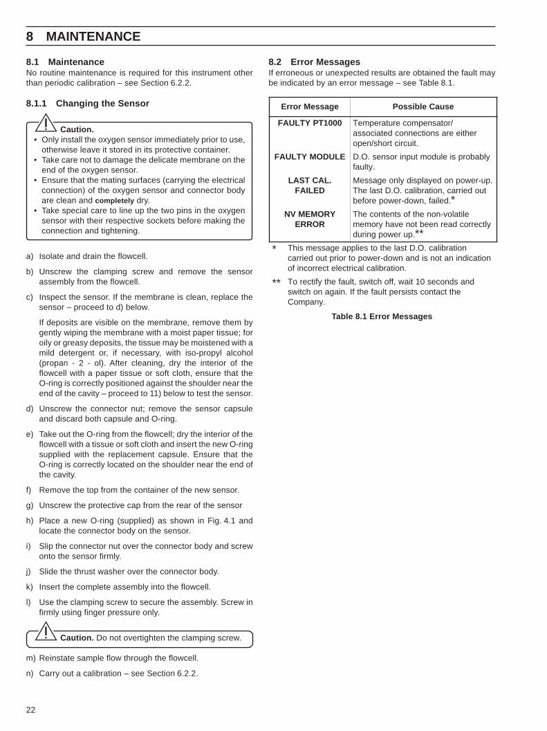
8.1 MaintenanceNo routine maintenance is required for this instrument otherthan periodic calibration – see Section 6.2.2.
8.1.1 Changing the Sensor
Caution.• Only install the oxygen sensor immediately prior to use,
otherwise leave it stored in its protective container.• Take care not to damage the delicate membrane on the
end of the oxygen sensor.• Ensure that the mating surfaces (carrying the electrical
connection) of the oxygen sensor and connector bodyare clean and completely dry.
• Take special care to line up the two pins in the oxygensensor with their respective sockets before making theconnection and tightening.
a) Isolate and drain the flowcell.
b) Unscrew the clamping screw and remove the sensorassembly from the flowcell.
c) Inspect the sensor. If the membrane is clean, replace thesensor – proceed to d) below.
If deposits are visible on the membrane, remove them bygently wiping the membrane with a moist paper tissue; foroily or greasy deposits, the tissue may be moistened with amild detergent or, if necessary, with iso-propyl alcohol(propan - 2 - ol). After cleaning, dry the interior of theflowcell with a paper tissue or soft cloth, ensure that theO-ring is correctly positioned against the shoulder near theend of the cavity – proceed to 11) below to test the sensor.
d) Unscrew the connector nut; remove the sensor capsuleand discard both capsule and O-ring.
e) Take out the O-ring from the flowcell; dry the interior of theflowcell with a tissue or soft cloth and insert the new O-ringsupplied with the replacement capsule. Ensure that theO-ring is correctly located on the shoulder near the end ofthe cavity.
f) Remove the top from the container of the new sensor.
g) Unscrew the protective cap from the rear of the sensor
h) Place a new O-ring (supplied) as shown in Fig. 4.1 andlocate the connector body on the sensor.
i) Slip the connector nut over the connector body and screwonto the sensor firmly.
j) Slide the thrust washer over the connector body.
k) Insert the complete assembly into the flowcell.
l) Use the clamping screw to secure the assembly. Screw infirmly using finger pressure only.
Caution. Do not overtighten the clamping screw.
m) Reinstate sample flow through the flowcell.
n) Carry out a calibration – see Section 6.2.2.
8.2 Error MessagesIf erroneous or unexpected results are obtained the fault maybe indicated by an error message – see Table 8.1.
Table 8.1 Error Messages
8 MAINTENANCE
egasseMrorrE esuaCelbissoP
0001TPYTLUAF /rotasnepmocerutarepmeTrehtieerasnoitcennocdetaicossa
.tiucrictrohs/nepo
ELUDOMYTLUAF ylbaborpsieludomtupnirosnes.O.D.ytluaf
.LACTSALDELIAF
.pu-rewopnodeyalpsidylnoegasseMtuodeirrac,noitarbilac.O.DtsalehT
.deliaf,nwod-rewoperofeb *YROMEMVN
RORREelitalov-nonehtfostnetnocehT
yltcerrocdaerneebtonevahyromem.purewopgnirud **
* noitarbilac.O.DtsalehtotseilppaegassemsihTnoitacidninatonsidnanwod-rewopotroirptuodeirrac
.noitarbilaclacirtceletcerrocnifo
** dnasdnoces01tiaw,ffohctiws,tluafehtyfitceroTehttcatnocstsisreptluafehtfI.niaganohctiws
.ynapmoC

23
9.1 Low Sensor Output or no Response to D.O.Changesa) Check that the sample drains fully from flowcell. If the
sample does NOT drain fully check:i) Operation of ball valve.ii) Sample inlet flow rate does not exceed 400 ml min–1
maximum.iii) Sample fluid paths are free flowing and clear of
partial blockages.iv) Ball valve drain tube is not kinked, blocked,
excessively long, does no rise along its length.v) Flow gauge is not blocked or dirty.
b) Replace the sensor (see Section 8.1.1) as an initial check.It is also important that all program parameters have beenset correctly and have not been altered inadvertently – seeSection 7.
If the fault persists:c) Carry out an electrical calibration as detailed in Section 7.5
and check that the instrument responds correctly to thecurrent input.
Failure to respond to the input usually indicates a fault withthe transmitter, which must be returned to the Company forrepair.
d) If the response in a) is correct, select the Operating Pageand set the current source to a value which gives an on-scale D.O. reading on the transmitter. Make a note of thecurrent source setting and the D.O. reading. Reconnectthe sensor cable and connect the current source to thesensor end of the cable. Set the same current value on thesource and check that the transmitter displays the notedreading in this configuration.
If check a) is correct but check b) fails, check the cableconnections and condition. If the response for both checks iscorrect, fit a new sensor and calibrate it.
9 SIMPLE FAULT FINDING
Table 9.1 Temperature Readings for Resistance Inputs
erutarepmeT(° )C
ecnatsiseRtupnI(Ω)
0 0.000101 0.930102 3.970103 7.611104 4.551105 0.491106 4.232107 7.072108 9.803109 0.7431001 0.58315.031 0.0051
9.2 Checking the Temperature InputCheck that the instrument responds to a temperature input.Disconnect the PT1000 leads and connect a suitableresistance box directly to the transmitter inputs – seeSection 7.5. Check that the transmitter displays the correctvalues as set on the resistance box – see Table 9.1.
Incorrect readings usually indicate an electrical calibrationproblem. Recalibrate the instrument – see Section 7.5.
9.3 High Sample ReadingsIf the sample reading is higher than expected, the most likelyreason is air ingress into the main sample line.Check and tighten ALL sample connections as it is possible tohave an air leak into the sample without sample leaking.

24
Flowcell mounting: Vertically using the built-in fixing bracket.
Protection—Flowcell Enclosure:IP54Transmitter: Model 4641: IP66 NEMA 4X
Model 4646: IP66 NEMA 4X front
Sampletemperature: 5 to 55 °C.
Sensor ambienttemperature: 0 to 55 °C.
Transmitter operatingtemperaturelimits: –20 to 55 °C.
Transmitter operatinghumidity limits: up to 95% RH non-condensing.
Storagetemperature limits—
Flowcell: –25 to 70 °C.Sensor: 0 to 55 °C.Transmitter: –25 to 70°C.
Sample flow: 100 to 500 ml/min.
Sample pressure: Maximum 2 bar.
Resolution: 0.1 µg/kg.
Accuracy: ±5% of reading or ±1 µg/kg, whichever isthe greater.
Stability: ±5% of reading or ±1µg/kg per week,whichever is the greater.
Response time: 90% of a step change in 1 minute.
Temperaturecompensation: 5 to 55 °C automatic using Pt1000
resistance thermometer.
Salinity correction: preset within the range 0 to 80 ppt.
Barometric pressurecorrection: preset within the range 500 to
800 mm Hg.
Transmitter display—Measured value: 5-digit x 7-segment back-lit l.c.d.
Information: 16-character, single line, dot matrixback-lit l.c.d.
Measuring ranges: 0 to 20.0, 0 to 200 µg/kg,0 to 2.00, 0 to 20.0 mg/kg.
Set Points and Relays—No. of set points: two.
Set pointadjustment: programmable.
Set pointhysteresis: ±1% of f.s.d. (fixed).
Local set pointannunciation: red l.e.d.
No. of relays: two.
Relay contacts: single pole changeover.
Rating: 250 V a.c. 250 V d.c. maximum.3 A a.c. 3 A d.c. maximum.
Loading:(noninductive)750 VA 30 W maximum.(inductive) 75 VA 3 W maximum.
Insulation, contactsto earth: 2 kV r.m.s.
Retransmission—No. of retransmissionsignals: one, fully isolated.
Output current: 0 to 10, 0 to 20 or 4 to 20 mAprogrammable.
Maximum loadresistance: 750 Ω (20 mA maximum).
Serialcommunication: RS422/RS485 (optional).
Power SupplyVoltage requirements:
100 to 130 V or200 to 260 V 50/60 Hz.
PowerConsumption: < 10 VA.
Error due to powersupply variations: less than ±2% for +6% –20% variation
from nominal supply voltage.
Insulation, mainsto earth: 2 kV r.m.s.
Mechanical DataMounting:
Model 4641 wall mounting, Model 4646panel mounting.
10 SPECIFICATION

25
Overall dimensions—in Environmental enclosure:
250 mm x 440 mm x 160 mm
Transmitter—Model 4641: 160 mm x 214 mm x 68 mm.Model 4646: 96 mm x 96 mm x 191 mm.
Panel cut-out: 92 mm x 92 mm.Weights—
Environmental enclosure(with sensorfitted): 4.0 kg.
Model 4641: 2 kg.Model 4646: 1.5 kg.
Sample connections –Compression fitting to accept either 6 mm or 1/4 in. o.d.tubing – to be specified when ordering.
10 SPECIFICATION

26
11.1 Strategic SparesPart No. Description ............................................... Qty0216 574 Flow Gauge assembly ................................... 1
PCB Assemblies,Wall Mounted9437 070 Complete main PCB assembly for single
current output ................................................. 19437 071 Complete main PCB assembly for single
current output + Serial/Modbus ..................... 19437 072 Complete main PCB assembly for two
current output version .................................... 14600 0295 Display PCB assembly .................................. 14600 0335 Low Level D.O. Module assembly ................. 14600 0405 2nd Retransmission output module
assembly ...................................................... 1Panel Mounted9437 075 Complete main PCB assembly (cropped)
for single current output ................................. 19437 076 Complete main PCB assembly (cropped)
for single current output + Serial/Modbus ..... 19437 077 Complete main PCB assembly (cropped)
for two current output version ........................ 14600 0246 Power supply PCB assembly (cropped) ........ 14600 0335 Low Level D.O. Module assembly ................. 14600 0405 2nd Retransmission output module
assembly ...................................................... 1
Test Equipment9439 950 Dissolved Oxygen Test Simulator .................. 19439 035 Test Simulator lead ........................................ 1
11 SPARES
27
11 SPARES
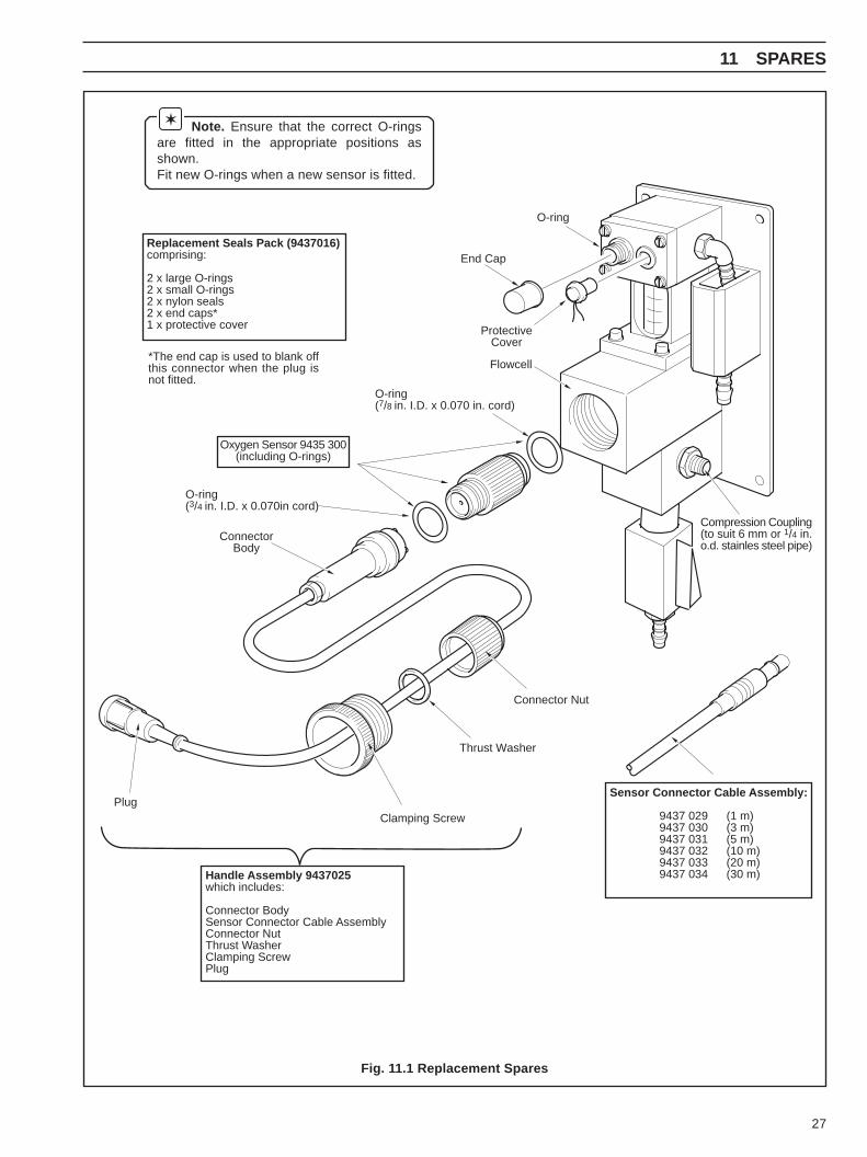
Note. Ensure that the correct O-ringsare fitted in the appropriate positions asshown.Fit new O-rings when a new sensor is fitted.
Fig. 11.1 Replacement Spares
Replacement Seals Pack (9437016)comprising:
2 x large O-rings2 x small O-rings2 x nylon seals2 x end caps*1 x protective cover
*The end cap is used to blank offthis connector when the plug isnot fitted.
End Cap
O-ring
ProtectiveCover
Flowcell
ConnectorBody
O-ring(3/4 in. I.D. x 0.070in cord)
Plug
Handle Assembly 9437025which includes:
Connector BodySensor Connector Cable AssemblyConnector NutThrust WasherClamping ScrewPlug
Clamping Screw
Thrust Washer
Connector Nut
Compression Coupling(to suit 6 mm or 1/4 in.o.d. stainles steel pipe)
Sensor Connector Cable Assembly:
9437 029 (1 m)9437 030 (3 m)9437 031 (5 m)9437 032 (10 m)9437 033 (20 m)9437 034 (30 m)
Oxygen Sensor 9435 300(including O-rings)
O-ring(7/8 in. I.D. x 0.070 in. cord)

28
NOTES

PRODUCTS & CUSTOMER SUPPORT
ProductsAutomation Systems
• for the following industries:– Chemical & Pharmaceutical– Food & Beverage– Manufacturing– Metals and Minerals– Oil, Gas & Petrochemical– Pulp and Paper
Drives and Motors• AC and DC Drives, AC and DC Machines, AC motors to 1kV• Drive systems• Force Measurement• Servo Drives
Controllers & Recorders• Single and Multi-loop Controllers• Circular Chart , Strip Chart and Paperless Recorders• Paperless Recorders• Process Indicators
Flexible Automation• Industrial Robots and Robot Systems
Flow Measurement• Electromagnetic Magnetic Flowmeters• Mass Flow Meters• Turbine Flowmeters• Wedge Flow Elements
Marine Systems & Turbochargers• Electrical Systems• Marine Equipment• Offshore Retrofit and Referbishment
Process Analytics• Process Gas Analysis• Systems Integration
Transmitters• Pressure• Temperature• Level• Interface Modules
Valves, Actuators and Positioners• Control Valves• Actuators• Positioners
Water, Gas & Industrial Analytics Instrumentation• pH, conductivity, and dissolved oxygen transmitters and
sensors• ammonia, nitrate, phosphate, silica, sodium, chloride,
fluoride, dissolved oxygen and hydrazine analyzers.• Zirconia oxygen analyzers, katharometers, hydrogen purity
and purge-gas monitors, thermal conductivity.
Customer Support
ABB Automation provides a comprehensive after sales servicevia a Worldwide Service Organization. Contact one of thefollowing offices for details on your nearest Service and RepairCentre.
United KingdomABB Automation LtdTel: +44 (0)1453 826 661Fax: +44 (0)1453 827 856
United States of AmericaABB Automation Inc.Tel: +1 (0) 755 883 4366Fax: +1 (0) 755 883 4373
Client Warranty
Prior to installation, the equipment referred to in this manualmust be stored in a clean, dry environment, in accordance withthe Company's published specification. Periodic checks must bemade on the equipment's condition.
In the event of a failure under warranty, the followingdocumentation must be provided as substantiation:
1. A listing evidencing process operation and alarm logs at timeof failure.
2. Copies of operating and maintenance records relating to thealleged faulty unit.

IM/9
437-
500
Issu
e 2
The Company’s policy is one of continuous productimprovement and the right is reserved to modify the informationcontained herein without notice.
© ABB 2001 Printed in UK (11.01)
ABB Automation LtdOldends Lane, StonehouseGloucestershire, GL10 3TAUKTel: +44 (0)1453 826 661Fax: +44 (0)1453 827 856
ABB Automation Inc2175 Lockheed WayCarson City, NV 89706USATel: +1 (0) 775 883 4366Fax: +1 (0) 775 883 4373
ABB has Sales & Customer Support expertise in over 100 countries worldwide
www.abb.com