Embed Size (px)
Citation preview
Model 903 907 912 914 Custom MUX
Video/Analog SignalsComposite (NTSC, PAL) l l l l
S-Video (Y/C) l l l
Component (YPbPr, RGB) l l l
Audio/Hydrophone l l l l
Analog Sonar (MS900) l l l l
Resolver/Encoder l l l
4-20 mA l l l
Sensor (Voltage Output) l l l
Digital Video SignalsSD-SDI (SMPTE 259M) l l l l
HD-SDI (SMPTE 292M) l l l l l
3G HD-SDI (SMTPE 424M) l l l l
CameraLink l
GigE Vision l l l l
Serial Data SignalsRS-232 l l l l
RS-485/422 l l l l
TTL l l l l
Responder Trigger l l l l
IRIG Timing l l l l
ECL/PECL l l l
LVDS l l l
On/Off Controls (TOR) l l l
Network/Bus Signals10/100M Ethernet l l l l l
Gigabit Ethernet l l l l l
10G Ethernet l
Tritech ARCNET l l l l
PROFIBUS l l l l
CAN Bus, Device Net l l l
EtherCAT, PROFINET l l l l
USB 2.0, 3.0 l
DiagnosticsLEDs On Board l l l l l
LEDS, External l l
Serial Port (RS-232) l l
Ethernet Port l l l
Modbus TCP/RTU l l l
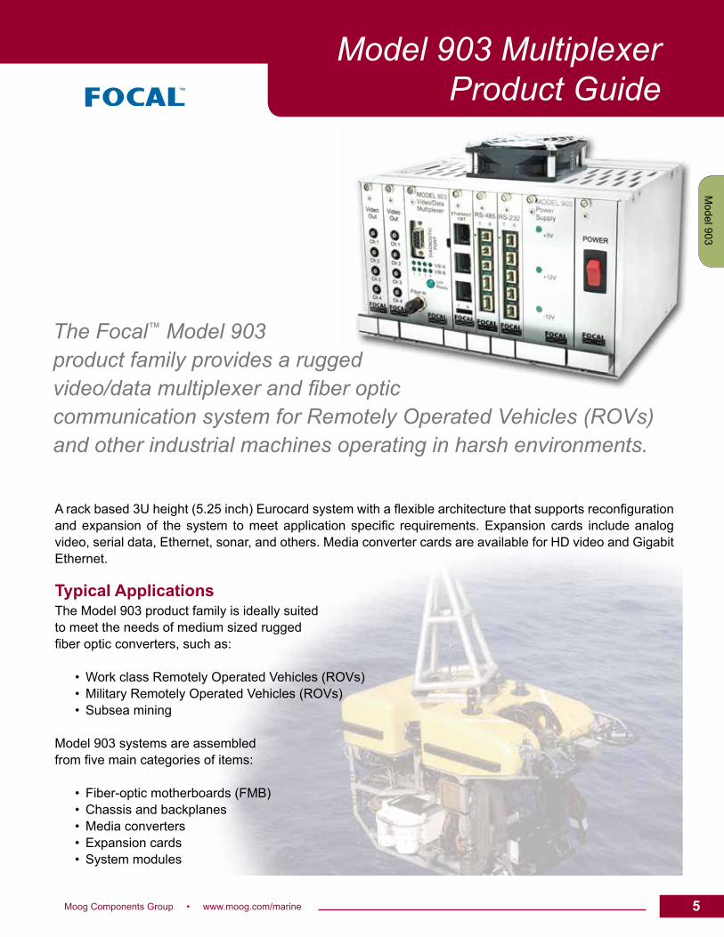
The Focal™ Model 903 product family provides a rugged video/data multiplexer and fiber optic communication system for Remotely Operated Vehicles (ROVs) and other industrial machines operating in harsh environments.
A rack based 3U height (5.25 inch) Eurocard system with a flexible architecture that supports reconfiguration and expansion of the system to meet application specific requirements. Expansion cards include analog video, serial data, Ethernet, sonar, and others. Media converter cards are available for HD video and Gigabit Ethernet.
Typical ApplicationsThe Model 903 product family is ideally suited to meet the needs of medium sized rugged fiber optic converters, such as:
• Work class Remotely Operated Vehicles (ROVs) • Military Remotely Operated Vehicles (ROVs) • Subsea mining
Model 903 systems are assembled from five main categories of items:
• Fiber-optic motherboards (FMB) • Chassis and backplanes • Media converters • Expansion cards • System modules
5Moog Components Group • www.moog.com/marine 55
Model 907
Model 903
Model 912
Model 914
Market S
pecificC
ustom
Model 903 MultiplexerProduct Guide
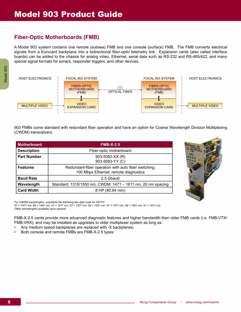
Fiber-Optic Motherboards (FMB) A Model 903 system contains one remote (subsea) FMB and one console (surface) FMB. The FMB converts electrical signals from a Eurocard backplane into a bidirectional fiber-optic telemetry link. Expansion cards (also called interface boards) can be added to the chassis for analog video, Ethernet, serial data such as RS-232 and RS-485/422, and many special signal formats for sonars, responder triggers, and other devices.
903 FMBs come standard with redundant fiber operation and have an option for Coarse Wavelength Division Multiplexing (CWDM) transceivers.
For CWDM wavelengths, substitute the following two digit code for XX/YY: 47 = 1471 nm, 49 = 1491 nm, 51 = 1511 nm, 53 = 1531 nm, 55 = 1551 nm, 57 = 1571 nm, 59 = 1591 nm, 61 = 1611 nm. Other wavelengths available upon request.
FMB-X-2.5 cards provide more advanced diagnostic features and higher bandwidth than older FMB cards (i.e. FMB-VTX/FMB-VRX), and may be installed as upgrades to older multiplexer system as long as:• Any medium speed backplanes are replaced with -X backplanes;• Both console and remote FMBs are FMB-X-2.5 types
Motherboard FMB-X-2.5Description Fiber-optic motherboardPart Number 903-5082-XX (R)
903-5083-YY (C)Features Redundant-fiber operation with auto fiber switching;
100 Mbps Ethernet; remote diagnosticsBaud Rate 2.5 GbaudWavelength Standard: 1310/1550 nm, CWDM: 1471 – 1611 nm, 20 nm spacingCard Width 8 HP (40.64 mm)
MULTIPLE VIDEO MULTIPLE VIDEO
HOST ELECTRONICS
FIBER-OPTICMOTHERBOARD
(FMB)
VIDEOEXPANSION CARD
FIBER-OPTICMOTHERBOARD
(FMB)
VIDEOEXPANSION CARD
FOCAL 903 SYSTEM FOCAL 903 SYSTEM HOST ELECTRONICS
OPTICAL FIBER
6 Moog Components Group • www.moog.com/marine
Mod
el 9
07M
odel
903
Mod
el 9
12M
odel
914
Mar
ket S
peci
ficC
usto
m
Model 903 Product Guide
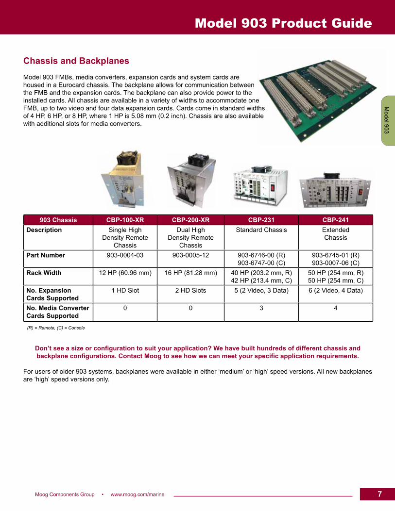
Chassis and BackplanesModel 903 FMBs, media converters, expansion cards and system cards are housed in a Eurocard chassis. The backplane allows for communication between the FMB and the expansion cards. The backplane can also provide power to the installed cards. All chassis are available in a variety of widths to accommodate one FMB, up to two video and four data expansion cards. Cards come in standard widths of 4 HP, 6 HP, or 8 HP, where 1 HP is 5.08 mm (0.2 inch). Chassis are also available with additional slots for media converters.
Don’t see a size or configuration to suit your application? We have built hundreds of different chassis and backplane configurations. Contact Moog to see how we can meet your specific application requirements.
For users of older 903 systems, backplanes were available in either ‘medium’ or ‘high’ speed versions. All new backplanes are ‘high’ speed versions only.
903 Chassis CBP-100-XR CBP-200-XR CBP-231 CBP-241Description Single High
Density RemoteChassis
Dual High Density Remote
Chassis
Standard Chassis ExtendedChassis
Part Number 903-0004-03 903-0005-12 903-6746-00 (R)903-6747-00 (C)
903-6745-01 (R)903-0007-06 (C)
Rack Width 12 HP (60.96 mm) 16 HP (81.28 mm) 40 HP (203.2 mm, R)42 HP (213.4 mm, C)
50 HP (254 mm, R)50 HP (254 mm, C)
No. ExpansionCards Supported
1 HD Slot 2 HD Slots 5 (2 Video, 3 Data) 6 (2 Video, 4 Data)
No. Media ConverterCards Supported
0 0 3 4
(R) = Remote, (C) = Console
7Moog Components Group • www.moog.com/marine 7
Model 907
Model 903
Model 912
Model 914
Market S
pecificC
ustom
Model 903 Product Guide
MediaConverter
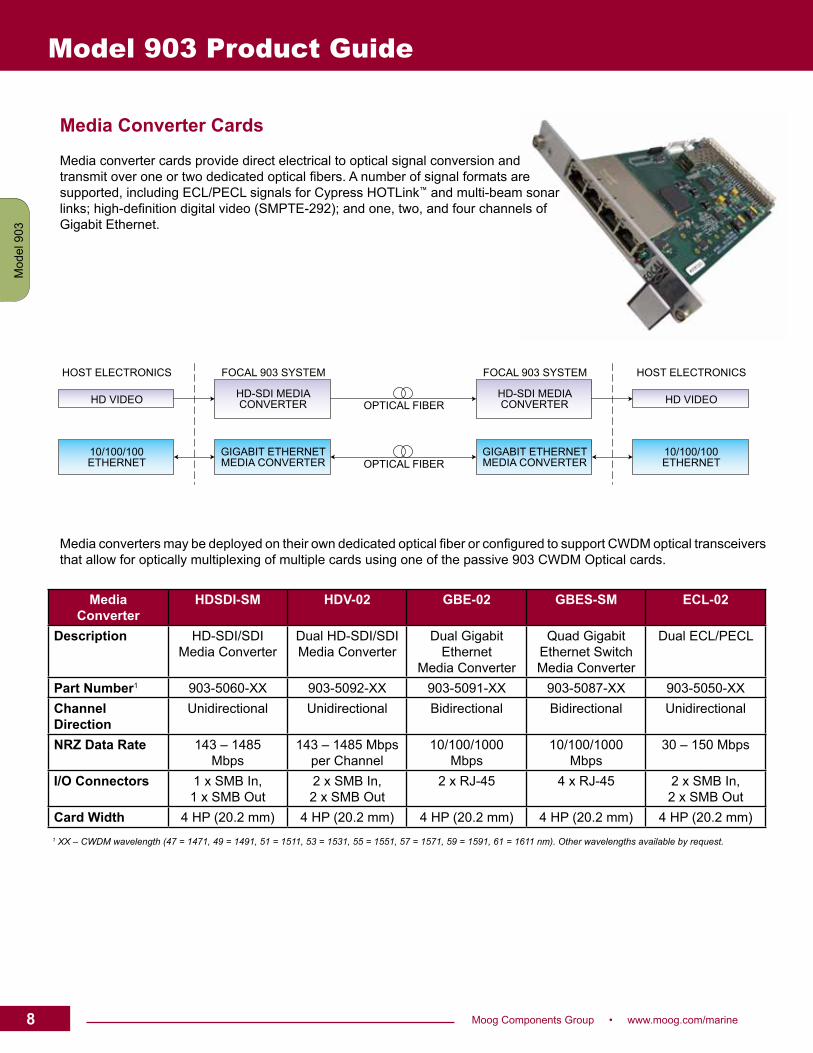
HDSDI-SM HDV-02 GBE-02 GBES-SM ECL-02
Description HD-SDI/SDIMedia Converter
Dual HD-SDI/SDIMedia Converter
Dual GigabitEthernet
Media Converter
Quad GigabitEthernet SwitchMedia Converter
Dual ECL/PECL
Part Number1 903-5060-XX 903-5092-XX 903-5091-XX 903-5087-XX 903-5050-XXChannelDirection
Unidirectional Unidirectional Bidirectional Bidirectional Unidirectional
NRZ Data Rate 143 – 1485Mbps
143 – 1485 Mbpsper Channel
10/100/1000Mbps
10/100/1000Mbps
30 – 150 Mbps
I/O Connectors 1 x SMB In, 1 x SMB Out
2 x SMB In, 2 x SMB Out
2 x RJ-45 4 x RJ-45 2 x SMB In, 2 x SMB Out
Card Width 4 HP (20.2 mm) 4 HP (20.2 mm) 4 HP (20.2 mm) 4 HP (20.2 mm) 4 HP (20.2 mm)1 XX – CWDM wavelength (47 = 1471, 49 = 1491, 51 = 1511, 53 = 1531, 55 = 1551, 57 = 1571, 59 = 1591, 61 = 1611 nm). Other wavelengths available by request.
Media Converter Cards
Media converter cards provide direct electrical to optical signal conversion and transmit over one or two dedicated optical fibers. A number of signal formats are supported, including ECL/PECL signals for Cypress HOTLink™ and multi-beam sonar links; high-definition digital video (SMPTE-292); and one, two, and four channels of Gigabit Ethernet.
Media converters may be deployed on their own dedicated optical fiber or configured to support CWDM optical transceivers that allow for optically multiplexing of multiple cards using one of the passive 903 CWDM Optical cards.
HD VIDEO
10/100/100ETHERNET
HOST ELECTRONICS
HD-SDI MEDIACONVERTER
HD-SDI MEDIACONVERTER
GIGABIT ETHERNETMEDIA CONVERTER
GIGABIT ETHERNETMEDIA CONVERTER
HD VIDEO
10/100/100ETHERNET
FOCAL 903 SYSTEM FOCAL 903 SYSTEM HOST ELECTRONICS
OPTICAL FIBER
OPTICAL FIBER
8 Moog Components Group • www.moog.com/marine
Mod
el 9
07M
odel
903
Mod
el 9
12M
odel
914
Mar
ket S
peci
ficC
usto
m
Model 903 Product Guide
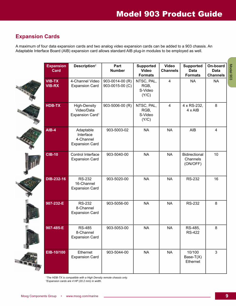
Expansion CardsA maximum of four data expansion cards and two analog video expansion cards can be added to a 903 chassis. An Adaptable Interface Board (AIB) expansion card allows standard AIB plug-in modules to be employed as well.
ExpansionCard
Description2 PartNumber
SupportedVideo
Formats
VideoChannels
SupportedData
Formats
On-boardData
ChannelsVIB-TXVIB-RX
4-Channel VideoExpansion Card
903-0014-00 (R)903-0015-00 (C)
NTSC, PAL,RGB,
S-Video (Y/C)
4 NA NA
HDB-TX High-Density Video/Data
Expansion Card1
903-5006-00 (R) NTSC, PAL,RGB,
S-Video(Y/C)
4 4 x RS-232, 4 x AIB
8
AIB-4 Adaptable Interface
4-Channel Expansion Card
903-5003-02 NA NA AIB 4
CIB-10 Control InterfaceExpansion Card
903-5040-00 NA NA BidirectionalChannels(ON/OFF)
10
DIB-232-16 RS-23216-Channel
Expansion Card
903-5020-00 NA NA RS-232 16
907-232-E RS-232 8-Channel
Expansion Card
903-5056-00 NA NA RS-232 8
907-485-E RS-485 8-Channel
Expansion Card
903-5053-00 NA NA RS-485, RS-422
8
EIB-10/100 Ethernet Expansion Card
903-5044-00 NA NA 10/100Base-T(X)Ethernet
3
1The HDB-TX is compatible with a High Density remote chassis only.2Expansion cards are 4 HP (20.2 mm) in width.
9Moog Components Group • www.moog.com/marine 9
Model 907
Model 903
Model 912
Model 914
Market S
pecificC
ustom
Model 903 Product Guide
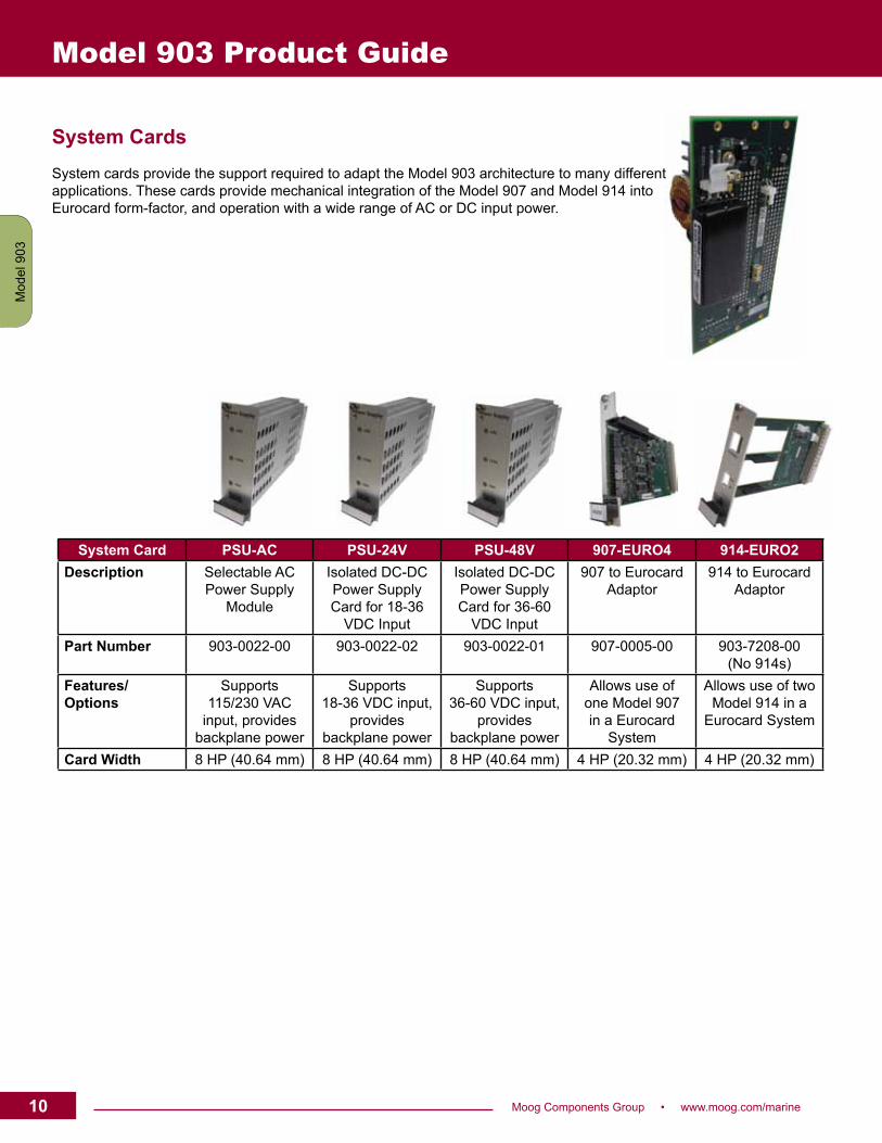
System CardsSystem cards provide the support required to adapt the Model 903 architecture to many different applications. These cards provide mechanical integration of the Model 907 and Model 914 into Eurocard form-factor, and operation with a wide range of AC or DC input power.
System Card PSU-AC PSU-24V PSU-48V 907-EURO4 914-EURO2Description Selectable AC
Power SupplyModule
Isolated DC-DCPower SupplyCard for 18-36
VDC Input
Isolated DC-DCPower SupplyCard for 36-60
VDC Input
907 to EurocardAdaptor
914 to EurocardAdaptor
Part Number 903-0022-00 903-0022-02 903-0022-01 907-0005-00 903-7208-00 (No 914s)
Features/Options
Supports115/230 VAC
input, providesbackplane power
Supports18-36 VDC input,
providesbackplane power
Supports36-60 VDC input,
providesbackplane power
Allows use ofone Model 907in a Eurocard
System
Allows use of twoModel 914 in a
Eurocard System
Card Width 8 HP (40.64 mm) 8 HP (40.64 mm) 8 HP (40.64 mm) 4 HP (20.32 mm) 4 HP (20.32 mm)
10 Moog Components Group • www.moog.com/marine
Mod
el 9
07M
odel
903
Mod
el 9
12M
odel
914
Mar
ket S
peci
ficC
usto
m
Model 903 Product Guide
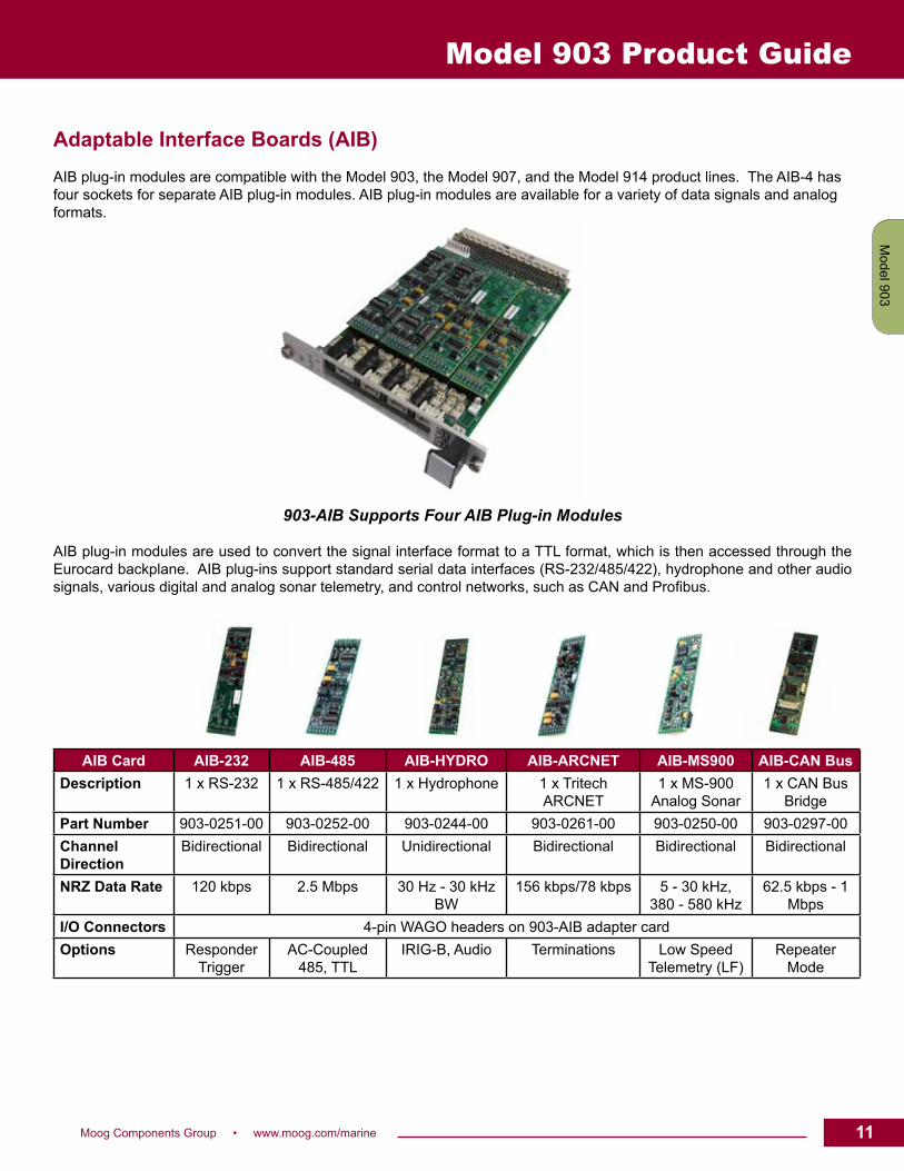
AIB Card AIB-232 AIB-485 AIB-HYDRO AIB-ARCNET AIB-MS900 AIB-CAN BusDescription 1 x RS-232 1 x RS-485/422 1 x Hydrophone 1 x Tritech
ARCNET1 x MS-900
Analog Sonar1 x CAN Bus
BridgePart Number 903-0251-00 903-0252-00 903-0244-00 903-0261-00 903-0250-00 903-0297-00ChannelDirection
Bidirectional Bidirectional Unidirectional Bidirectional Bidirectional Bidirectional
NRZ Data Rate 120 kbps 2.5 Mbps 30 Hz - 30 kHzBW
156 kbps/78 kbps 5 - 30 kHz, 380 - 580 kHz
62.5 kbps - 1Mbps
I/O Connectors 4-pin WAGO headers on 903-AIB adapter cardOptions Responder
TriggerAC-Coupled
485, TTLIRIG-B, Audio Terminations Low Speed
Telemetry (LF)Repeater
Mode
Adaptable Interface Boards (AIB)AIB plug-in modules are compatible with the Model 903, the Model 907, and the Model 914 product lines. The AIB-4 has four sockets for separate AIB plug-in modules. AIB plug-in modules are available for a variety of data signals and analog formats.
903-AIB Supports Four AIB Plug-in Modules
AIB plug-in modules are used to convert the signal interface format to a TTL format, which is then accessed through the Eurocard backplane. AIB plug-ins support standard serial data interfaces (RS-232/485/422), hydrophone and other audio signals, various digital and analog sonar telemetry, and control networks, such as CAN and Profibus.
11Moog Components Group • www.moog.com/marine 11
Model 907
Model 903
Model 912
Model 914
Market S
pecificC
ustom
Model 903 Product Guide
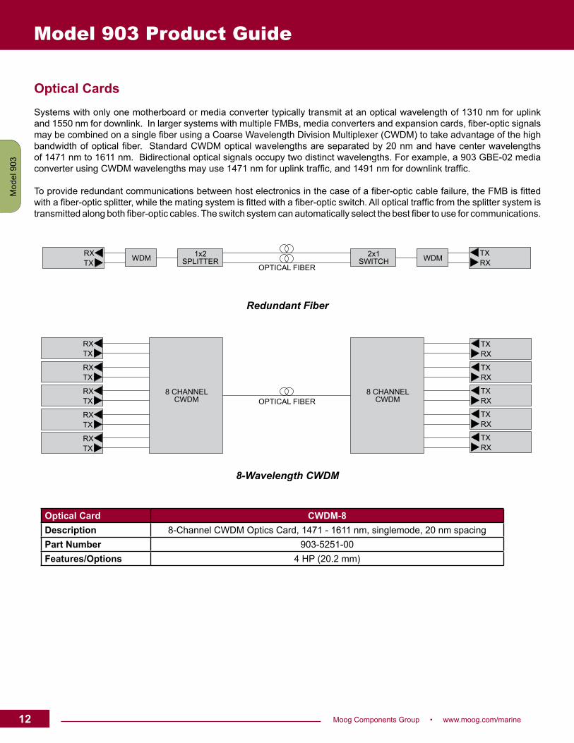
Optical CardsSystems with only one motherboard or media converter typically transmit at an optical wavelength of 1310 nm for uplink and 1550 nm for downlink. In larger systems with multiple FMBs, media converters and expansion cards, fiber-optic signals may be combined on a single fiber using a Coarse Wavelength Division Multiplexer (CWDM) to take advantage of the high bandwidth of optical fiber. Standard CWDM optical wavelengths are separated by 20 nm and have center wavelengths of 1471 nm to 1611 nm. Bidirectional optical signals occupy two distinct wavelengths. For example, a 903 GBE-02 media converter using CWDM wavelengths may use 1471 nm for uplink traffic, and 1491 nm for downlink traffic.
To provide redundant communications between host electronics in the case of a fiber-optic cable failure, the FMB is fitted with a fiber-optic splitter, while the mating system is fitted with a fiber-optic switch. All optical traffic from the splitter system is transmitted along both fiber-optic cables. The switch system can automatically select the best fiber to use for communications.
Redundant Fiber
8-Wavelength CWDM
Optical Card CWDM-8Description 8-Channel CWDM Optics Card, 1471 - 1611 nm, singlemode, 20 nm spacingPart Number 903-5251-00Features/Options 4 HP (20.2 mm)
RXTX WDM 1x2
SPLITTER2x1
SWITCH WDMTXRXOPTICAL FIBER
8 CHANNELCWDM
8 CHANNELCWDM
RXTX
RXTX
RXTX
RXTX
RXTX
TXRX
TXRX
TXRX
TXRX
TXRX
OPTICAL FIBER
12 Moog Components Group • www.moog.com/marine
Mod
el 9
07M
odel
903
Mod
el 9
12M
odel
914
Mar
ket S
peci
ficC
usto
m
Model 903 Product Guide
13Moog Components Group • www.moog.com/marine 13
Model 907
Model 903
Model 912
Model 914
Market S
pecificC
ustom
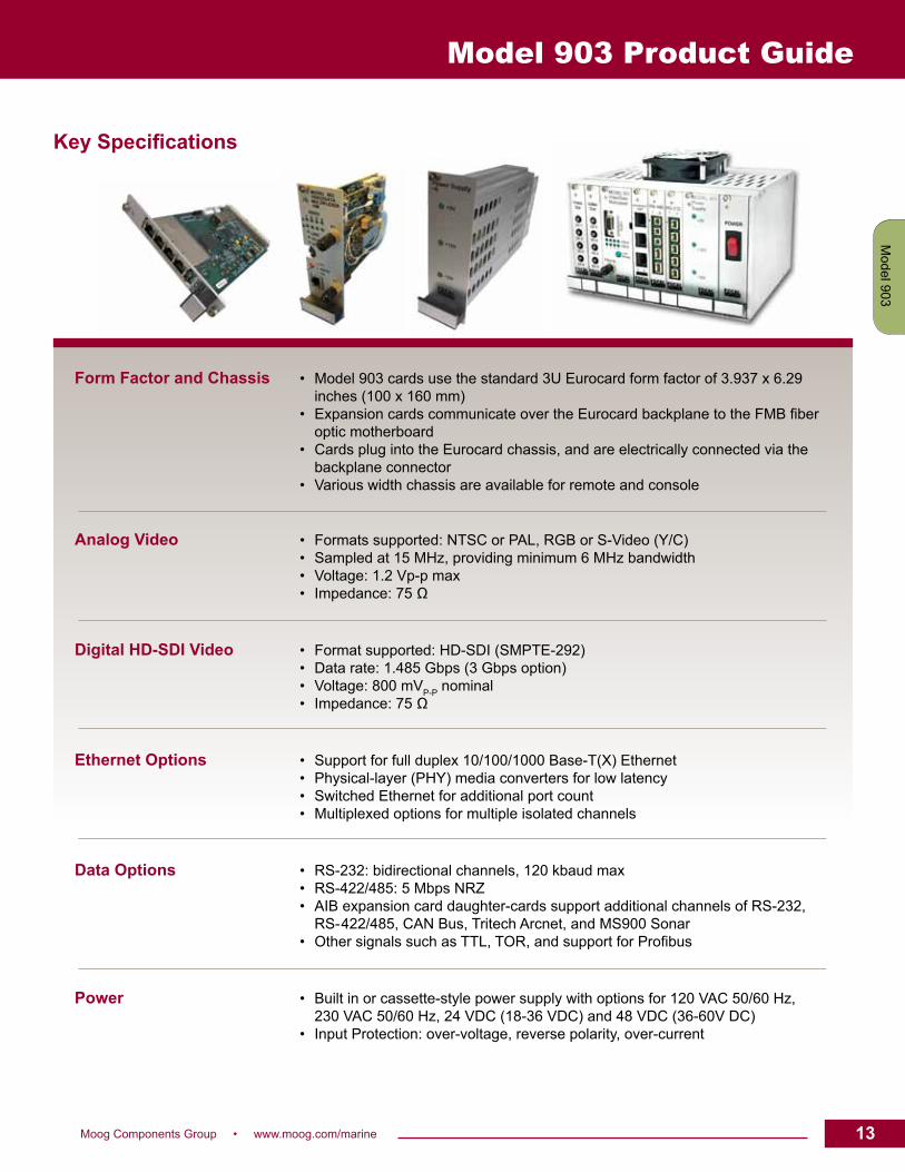
Form Factor and Chassis • Model 903 cards use the standard 3U Eurocard form factor of 3.937 x 6.29 inches (100 x 160 mm) • Expansion cards communicate over the Eurocard backplane to the FMB fiber optic motherboard • Cards plug into the Eurocard chassis, and are electrically connected via the backplane connector • Various width chassis are available for remote and console
Analog Video • Formats supported: NTSC or PAL, RGB or S-Video (Y/C) • Sampled at 15 MHz, providing minimum 6 MHz bandwidth • Voltage: 1.2 Vp-p max • Impedance: 75 Ω
Digital HD-SDI Video • Format supported: HD-SDI (SMPTE-292) • Data rate: 1.485 Gbps (3 Gbps option) • Voltage: 800 mVP-P nominal • Impedance: 75 Ω
Ethernet Options • Support for full duplex 10/100/1000 Base-T(X) Ethernet • Physical-layer (PHY) media converters for low latency • Switched Ethernet for additional port count • Multiplexed options for multiple isolated channels
Data Options • RS-232: bidirectional channels, 120 kbaud max • RS-422/485: 5 Mbps NRZ • AIB expansion card daughter-cards support additional channels of RS-232, RS- 422/485, CAN Bus, Tritech Arcnet, and MS900 Sonar • Other signals such as TTL, TOR, and support for Profibus
Power • Built in or cassette-style power supply with options for 120 VAC 50/60 Hz, 230 VAC 50/60 Hz, 24 VDC (18-36 VDC) and 48 VDC (36-60V DC) • Input Protection: over-voltage, reverse polarity, over-current
Key Specifications
Model 903 Product Guide
14 Moog Components Group • www.moog.com/marine
Mod
el 9
07M
odel
903
Mod
el 9
12M
odel
914
Mar
ket S
peci
ficC
usto
m
Model 903 Product Guide
Optical Options • Optical Fiber: 1 or 2 singlemode (9/125 μm) • Wavelengths: 1310/1550 nm standard, CWDM options available • Flux Budget: 20 dB minimum standard (others available) • Connectors: ST, others available
Diagnostics Support • Diagnostics extracted from the FMB cards in both remote and console stacks using a 10 Base-T Ethernet or RS-232 link • Optical transceiver data including Tx-power, Rx-power, bias current, temperature, voltage and more • Card identity, serial number • Built-in web server • Terminal diagnostics through RS-232 port on FMB • Compatible with VDM software
Call or email our knowledgeable Application Engineers for more information: 902-468-2263 or [email protected]