Embed Size (px)
Citation preview
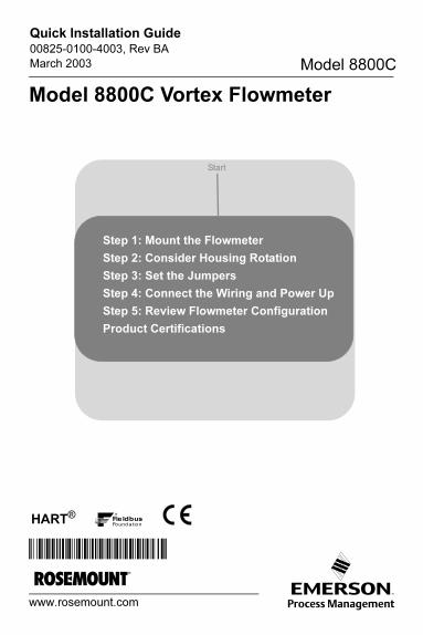
www.rosemount.com
¢00825-0100-4003g¤
HART®
Quick Installation Guide00825-0100-4003, Rev BA
March 2003 Model 8800C
Model 8800C Vortex Flowmeter
Step 1: Mount the Flowmeter
Step 2: Consider Housing Rotation
Step 3: Set the Jumpers
Step 4: Connect the Wiring and Power Up
Step 5: Review Flowmeter Configuration
Product Certifications
Start
4003_revBA_qig.fm Page 1 Monday, March 31, 2003 7:51 AM

Quick Installation Guide00825-0100-4003, Rev BA
March 2003 Model 8800C
© 2003 Rosemount Inc. All rights reserved. All marks property of owner.
IMPORTANT NOTICE
This installation guide provides basic guidelines for the
Rosemount® Model 8800C Vortex Flowmeter. It does not provide
instructions for detailed configuration, diagnostics, maintenance,
service, troubleshooting, Explosion-Proof, Flame-Proof, or
Intrinsically Safe (I.S.) installations. Refer to the Model 8800C
reference manual (document number 00809-0100-4003) and Model
8800C Foundation fieldbus manual (document number
00809-0100-4772) for more instruction. The manuals and this QIG
are also available electronically on www.rosemount.com.
Rosemount Inc.8200 Market BoulevardChanhassen, MN USA 55317T (US) (800) 999-9307T (Intnl) (952) 906-8888F (952) 949-7001
4003_revBA_qig.fm Page 2 Monday, March 31, 2003 7:51 AM
Quick Installation Guide00825-0100-4003, Rev BA
March 2003 Model 8800C
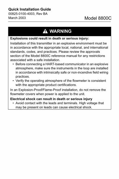
WARNING
Explosions could result in death or serious injury:
Installation of this transmitter in an explosive environment must be
in accordance with the appropriate local, national, and international
standards, codes, and practices. Please review the approvals
section of the Model 8800C reference manual for any restrictions
associated with a safe installation.
• Before connecting a HART-based communicator in an explosive
atmosphere, make sure the instruments in the loop are installed
in accordance with intrinsically safe or non-incendive field wiring
practices.
• Verify the operating atmosphere of the flowmeter is consistent
with the appropriate product certifications.
In an Explosion-Proof/Flame-Proof installation, do not remove the
flowmeter covers when power is applied to the unit.
Electrical shock can result in death or serious injury
• Avoid contact with the leads and terminals. High voltage that
may be present on leads can cause electrical shock.
4003_revBA_qig.fm Page 3 Monday, March 31, 2003 7:51 AM
Quick Installation Guide00825-0100-4003, Rev BA
March 2003 Model 8800C
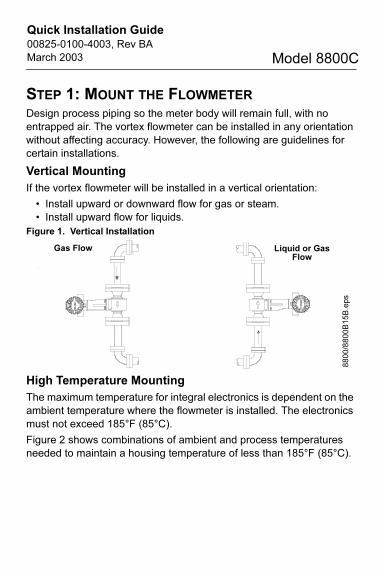
STEP 1: MOUNT THE FLOWMETER
Design process piping so the meter body will remain full, with no
entrapped air. The vortex flowmeter can be installed in any orientation
without affecting accuracy. However, the following are guidelines for
certain installations.
Vertical Mounting
If the vortex flowmeter will be installed in a vertical orientation:
• Install upward or downward flow for gas or steam.
• Install upward flow for liquids.
Figure 1. Vertical Installation
High Temperature Mounting
The maximum temperature for integral electronics is dependent on the
ambient temperature where the flowmeter is installed. The electronics
must not exceed 185°F (85°C).
Figure 2 shows combinations of ambient and process temperatures
needed to maintain a housing temperature of less than 185°F (85°C).
Liquid or Gas Flow
Gas Flow
8800/8800B15B.eps
4003_revBA_qig.fm Page 4 Monday, March 31, 2003 7:51 AM

Quick Installation Guide00825-0100-4003, Rev BA
March 2003 Model 8800C
Figure 2. Model 8800C Ambient/Process Temperature Limits
The following orientations are recommended for applications with high
process temperatures.
• Install with meter body beside or below process pipe.
• Insulation around pipe may be necessary to maintain ambient temperature below 185°F (85°C).
NOTE
Insulate pipe and meter body only. Do not insulate support tube
bracket so heat can be dissipated.
Figure 3. High Temperature Installation
200 (93)
180 (82)
160 (71)
140 (60)
120 (49)
100 (38)
80 (27)
60 (16)
0
20
0 (
93
)
30
0 (
14
9)
40
0 (
20
4)
50
0 (
26
0)
60
0 (
31
6)
70
0 (
37
1)
80
0 (
42
7)
90
0 (
48
2)
10
00
(5
38
)
10
0 (
38
)Am
bie
nt
Tem
pe
ratu
re °
F (
°C)
Process Temperature °F (°C)
185°F Housing Temperature Limit
Meter and pipe insulated with 3 inches of ceramic fiber insulation. Horizontal Pipe and Vertical meter position.
8800_26aa.eps
The meter body installed with the electronics to
the side of the pipe
The meter body installedwith the electronics
below the pipe
4003_revBA_qig.fm Page 5 Monday, March 31, 2003 7:51 AM

Quick Installation Guide00825-0100-4003, Rev BA
March 2003 Model 8800C
For steam and fluids with small solids content, it is recommended to
have the flowmeter installed with the electronics to the side of the pipe.
This will minimize potential measurement errors by allowing the
condensate or solids to flow under the shedder bar without interrupting
the vortex shedding.
Steam Installations
Avoid installation shown Figure 4. Such conditions may cause a
water-hammer condition at startup due to trapped condensation.
Figure 4. Improper Installation
8800g15c
4003_revBA_qig.fm Page 6 Monday, March 31, 2003 7:51 AM
Quick Installation Guide00825-0100-4003, Rev BA
March 2003 Model 8800C
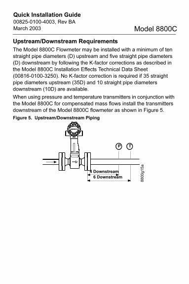
Upstream/Downstream Requirements
The Model 8800C Flowmeter may be installed with a minimum of ten
straight pipe diameters (D) upstream and five straight pipe diameters
(D) downstream by following the K-factor corrections as described in
the Model 8800C Installation Effects Technical Data Sheet
(00816-0100-3250). No K-factor correction is required if 35 straight
pipe diameters upstream (35D) and 10 straight pipe diameters
downstream (10D) are available.
When using pressure and temperature transmitters in conjunction with
the Model 8800C for compensated mass flows install the transmitters
downstream of the Model 8800C flowmeter as shown in Figure 5.
Figure 5. Upstream/Downstream Piping
P T
4 Downstream
6 Downstream
8800g15a
4003_revBA_qig.fm Page 7 Monday, March 31, 2003 7:51 AM
Quick Installation Guide00825-0100-4003, Rev BA
March 2003 Model 8800C
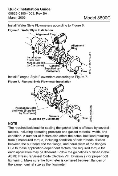
Install Wafer Style Flowmeters according to Figure 6.
Figure 6. Wafer Style Installation
Install Flanged-Style Flowmeters according to Figure 7.
Figure 7. Flanged-Style Flowmeter Installation
NOTE
The required bolt load for sealing the gasket joint is affected by several
factors, including operating pressure and gasket material, width, and
condition. A number of factors also affect the actual bolt load resulting
from a measured torque, including condition of bolt threads, friction
between the nut head and the flange, and parallelism of the flanges.
Due to these application-dependent factors, the required torque for
each application may be different. Follow the guidelines outlined in the
ASME Pressure Vessel Code (Section VIII, Division 2) for proper bolt
tightening. Make sure the flowmeter is centered between flanges of
the same nominal size as the flowmeter.
Flow
8800-0465A01d.eps
Gaskets(Supplied by
Customer)
Installation Studs and Nuts (Supplied by Customer)
Alignment Ring
Alignment Ring
Gaskets(Supplied by Customer)
Installation Boltsand Nuts (Supplied
by Customer)
Flow
8800-065A02B
4003_revBA_qig.fm Page 8 Monday, March 31, 2003 7:51 AM

Quick Installation Guide00825-0100-4003, Rev BA
March 2003 Model 8800C
Remote Electronics
If you order one of the remote electronics options (options R10, R20,
R30, or RXX), the flowmeter assembly ships in two parts:
1. The meter body with an adapter installed in the support tube and
an interconnecting coaxial cable attached to it.
2. The electronics housing installed on a mounting bracket.
Mounting
Mount the meter body in the process flow line as described earlier in
this section. Mount the bracket and electronics housing in the desired
location. The housing can be repositioned on the bracket to facilitate
field wiring and conduit routing.
Cable Connections
Refer to Figure 8 and the instructions on page 10 to connect the loose
end of the coaxial cable to the electronics housing.
Figure 8. Remote Electronics Installation
* Access Cover is available only in 6 inch (DN50) and 8 inch (DN 200) wafer style flowmeters.
Electronics Housing
GroundConnection
HousingAdapter
Optional ½–14 NPT Conduit Adapter or Cable Gland *
Mounting Bracket for Wall or 2-Inch Pipe
CoaxialCable
HousingBase
Meter Adapter
Optional ½–14 NPT Conduit Adapter or Cable Gland *
Insulating Disk
Sensor Connection
SupportTube
Meter Body
AccessCover *
WasherNut
4003_revBA_qig.fm Page 9 Monday, March 31, 2003 7:51 AM

Quick Installation Guide00825-0100-4003, Rev BA
March 2003 Model 8800C
1. If you plan to run the coaxial cable in conduit, carefully cut the
conduit to the desired length to provide for proper assembly at the
housing. A junction box may be placed in the conduit run to provide
a space for extra coaxial cable length.
2. Slide the conduit adapter or cable gland over the loose end of the
coaxial cable and fasten it to the adapter on the meter body
support tube.
3. If using conduit, route the coaxial cable through the conduit.
4. Place a conduit adapter or cable gland over the end of the coaxial
cable.
5. Remove the housing adapter from the electronics housing.
6. Slide the housing adapter over the coaxial cable.
7. Remove one of the four housing base screws.
8. Attach and securely tighten the coaxial cable nut to the connection
on the electronics housing.
9. Attach the coaxial cable ground wire to the housing via the housing
base ground screw.
10.Align the housing adapter with the housing and attach
with three screws.
11. Tighten the conduit adapter or cable gland to the
housing adapter.
CAUTION
To prevent moisture from entering the coaxial cable connections,
install the interconnecting coaxial cable in a single dedicated conduit
run or use sealed cable glands at both ends of the cable.
4003_revBA_qig.fm Page 10 Monday, March 31, 2003 7:51 AM

Quick Installation Guide00825-0100-4003, Rev BA
March 2003 Model 8800C
STEP 2: CONSIDER HOUSING ROTATION
The entire electronics housing may be rotated in 90 degree increments
for easy viewing. Use the following steps to change the housing
orientation:
1. Loosen the screw on the access cover (on the support tube) and
remove the cover (6 inch [DN150] and 8 inch [DN 200] Wafer Style
only).
2. Loosen the three housing rotation set screws at the base of the
electronics housing with a hex wrench by turning the screws
clockwise (inward) until they will clear the support tube.
3. Slowly pull the electronics housing out of the support tube.
NOTE
Do not pull the housing more than 1.5 inches (40 mm) from the top of
the support tube until the sensor cable is disconnected. Damage to the
sensor may occur if this sensor cable is stressed.
4. Unscrew the sensor cable from the housing with a 5/16-inch open
end wrench.
5. Rotate the housing to the desired orientation.
6. Hold it in this orientation while you screw the sensor cable onto the
base of the housing.
NOTE
Do not rotate the housing while the sensor cable is attached to the
base of the housing. This will stress the cable and may damage the
sensor.
7. Place the electronics housing into the top of the support tube.
8. Use a hex wrench to turn the three housing rotation screws
counter-clockwise (outward) to engage the support tube.
9. Replace the access cover on the support tube and then tighten the
screw (6 inch [DN150] and 8 inch [DN 200] Wafer Style only).
4003_revBA_qig.fm Page 11 Monday, March 31, 2003 7:51 AM
Quick Installation Guide00825-0100-4003, Rev BA
March 2003 Model 8800C
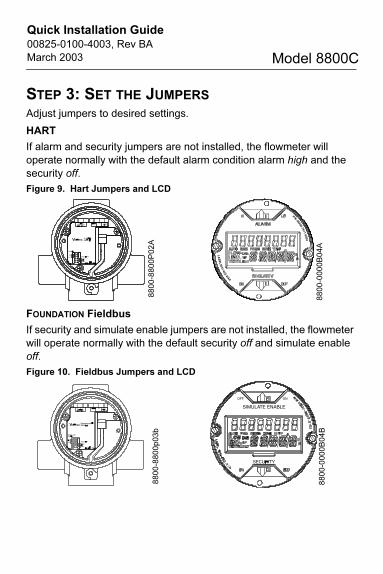
STEP 3: SET THE JUMPERS
Adjust jumpers to desired settings.
HART
If alarm and security jumpers are not installed, the flowmeter will
operate normally with the default alarm condition alarm high and the
security off.
Figure 9. Hart Jumpers and LCD
FOUNDATION Fieldbus
If security and simulate enable jumpers are not installed, the flowmeter
will operate normally with the default security off and simulate enable
off.
Figure 10. Fieldbus Jumpers and LCD
8800-8800P02A
8800-0000B04A
8800-8800p03b
8800-0000B04B
4003_revBA_qig.fm Page 12 Monday, March 31, 2003 7:51 AM

Quick Installation Guide00825-0100-4003, Rev BA
March 2003 Model 8800C
STEP 4: CONNECT THE WIRING AND POWER UP
Power Supply
HART
The dc power supply should provide power with less than two percent
ripple. The total resistance load is the sum of the resistance of the
signal leads and the load resistance of the controller, indicator, and
related pieces. Note that the resistance of intrinsic safety barriers, if
used, must be included.
Figure 11. Load LimitationMaximum Loop Resistance = 41.7 (Power Supply Voltage - 10.8)
The HART Communicator requires a minimum loop resistance of 250Ω
FOUNDATION fieldbus
The flowmeter requires 9-32V dc at the power terminals. Each fieldbus
power supply requires a power conditioner to decouple the power
supply output from the fieldbus wiring segment.
Power Supply (Volts)
Operating Region
1250
1000
500
0 10.8 42
Lo
ad
(O
hm
s)
4003_revBA_qig.fm Page 13 Monday, March 31, 2003 7:51 AM
Quick Installation Guide00825-0100-4003, Rev BA
March 2003 Model 8800C
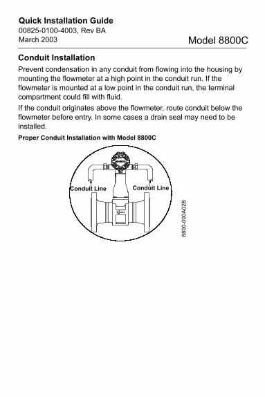
Conduit Installation
Prevent condensation in any conduit from flowing into the housing by
mounting the flowmeter at a high point in the conduit run. If the
flowmeter is mounted at a low point in the conduit run, the terminal
compartment could fill with fluid.
If the conduit originates above the flowmeter, route conduit below the
flowmeter before entry. In some cases a drain seal may need to be
installed.
Proper Conduit Installation with Model 8800C
Conduit Line Conduit Line8800-000A02B
4003_revBA_qig.fm Page 14 Monday, March 31, 2003 7:51 AM
Quick Installation Guide00825-0100-4003, Rev BA
March 2003 Model 8800C
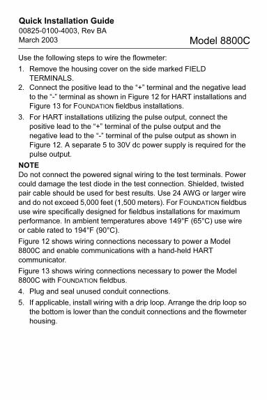
Use the following steps to wire the flowmeter:
1. Remove the housing cover on the side marked FIELD
TERMINALS.
2. Connect the positive lead to the “+” terminal and the negative lead
to the “-” terminal as shown in Figure 12 for HART installations and
Figure 13 for FOUNDATION fieldbus installations.
3. For HART installations utilizing the pulse output, connect the
positive lead to the “+” terminal of the pulse output and the
negative lead to the “-” terminal of the pulse output as shown in
Figure 12. A separate 5 to 30V dc power supply is required for the
pulse output.
NOTE
Do not connect the powered signal wiring to the test terminals. Power
could damage the test diode in the test connection. Shielded, twisted
pair cable should be used for best results. Use 24 AWG or larger wire
and do not exceed 5,000 feet (1,500 meters). For FOUNDATION fieldbus
use wire specifically designed for fieldbus installations for maximum
performance. In ambient temperatures above 149°F (65°C) use wire
or cable rated to 194°F (90°C).
Figure 12 shows wiring connections necessary to power a Model
8800C and enable communications with a hand-held HART
communicator.
Figure 13 shows wiring connections necessary to power the Model
8800C with FOUNDATION fieldbus.
4. Plug and seal unused conduit connections.
5. If applicable, install wiring with a drip loop. Arrange the drip loop so
the bottom is lower than the conduit connections and the flowmeter
housing.
4003_revBA_qig.fm Page 15 Monday, March 31, 2003 7:51 AM

Quick Installation Guide00825-0100-4003, Rev BA
March 2003 Model 8800C
Figure 12. Flowmeter Wiring Diagrams for HART protocol
NOTE
Installation of the transient protection terminal block does not provide
transient protection unless the Model 8800C case is properly
grounded.
4-20mA Wiring
4-20mA and Pulse Wiring with Electronic Totalizer/Counter
RL ≥ 250 ΩPower Supply
+
-
Test Ammeter
RL ≥ 250 Ω+
++
+
––
Test Ammeter
4003_revBA_qig.fm Page 16 Monday, March 31, 2003 7:51 AM

Quick Installation Guide00825-0100-4003, Rev BA
March 2003 Model 8800C
Figure 13. Flowmeter Wiring Diagram for FOUNDATION fieldbus protocol Field Wiring Diagram
Power Supply
Terminators
6234 ft (1900 m) max(depending upon cable
characteristics)Integrated
PowerConditioner
and Filter
(Trunk)
(Spur)
(Spur)
* Intrinsically safe installations may allow fewer devices per I.S. barrier.
(The power supply, filter, first terminator, and configuration tool are typically located in the control room.)
FieldbusSegment
Devices 1 through 16*8800-3144_01A
FOUNDATION Fieldbus
Configuration Tool
4003_revBA_qig.fm Page 17 Monday, March 31, 2003 7:51 AM
Quick Installation Guide00825-0100-4003, Rev BA
March 2003 Model 8800C
STEP 5: REVIEW FLOWMETER CONFIGURATION
Before operating the Model 8800C in an installation, you should review
the configuration data to ensure that it reflects the current application.
In most cases, all of these variables are pre-configured at the factory.
Configuration may be required if your Model 8800C is not configured
or if the configuration variables need revision.
Rosemount recommends the following variables are reviewed before
startup:
• Service Type
• PV Units
• Process Density and Density Units(Only when mass flow units are selected).
• Range Values
• Process Temperature
• Mating Pipe ID
• K-FactorNOTE
For detailed configuration information see the Model 8800C Vortex
Flowmeter manual (00809-0100-4003) and the Model 8800C
FOUNDATION fieldbus manual (00809-0100-4772).
4003_revBA_qig.fm Page 18 Monday, March 31, 2003 7:51 AM

Quick Installation Guide00825-0100-4003, Rev BA
March 2003 Model 8800C
Table 1. Fast Keys for Model 8800C
Alarm Jumper HART Fast Key Function HART Fast Key
Alarm Jumpers 1, 4, 3, 1, 3 Num Req Preams 1, 4, 3, 3, 2
Analog Output 1, 4, 3, 1 Poll Address 1, 4, 3, 3, 1
Base Time Unit 1, 3, 3, 5, 2 Process Density 1, 3, 3, 2, 2
Base Volume Unit 1, 3, 3, 5, 1 Process Temperature
1, 3, 5
Burst Mode 1, 4, 3, 3, 3 Process Variables 1, 1
Burst Option 1, 4, 3, 3, 4 Pulse Output 1, 4, 3, 2
Conversion Number
1, 3, 3, 5, 4 Pulse Output Scale 1, 4, 3, 2, 1
D/A Trim 1, 4, 3, 1, 4 Pulse Output Test 1, 4, 3, 2, 2
Damping 1, 3, 7 PV Percent Range 1, 1, 2
Date 1, 4, 5, 5 Range Values 1, 3, 4
Descriptor 1, 4, 5, 3 Review 1, 5
Density Ratio 1, 3, 3, 3, 2 Revision Numbers 1, 4, 5, 7
Device ID 1, 4, 5, 7, 6 Scaled D/A Trim 1, 2, 6 or 1, 4, 3, 1, 5
Filter Restore 1, 4, 4, 3 Self Test 1, 2, 1, 2
Final Assembly Number
1, 4, 5, 7, 5 Service Type 1, 3, 2
Flange Type 1, 4, 1, 5 STD/ Nor Flow Units 1, 3, 3, 3, 1
K-Factor 1, 4, 1, 2 Special Units 1, 3, 3, 5
Local Display 1, 4, 3, 4 Status 1, 2, 1, 1
Loop Test 1, 4, 3, 1, 2 Tag 1, 3, 1
Low Flow Cutoff 1, 4, 4, 2, 3 Total 1, 1, 4, 1
Low Pass Filter 1, 4, 4, 2, 4 Totalizer Control 1, 1, 4
LRV 1, 3, 4, 2 Transmitter Test 1, 2, 1, 2
LSL 1, 3, 4, 5 Trigger Level 1, 4, 4, 2, 5
Manufacturer 1, 4, 5, 1 URV 1, 3, 4, 1
Mass Flow Units 1, 3, 3, 2, 1 User Defined Units 1, 3, 3, 5, 3
Mating Pipe ID (Inside Diameter)
1, 3, 6 USL 1, 3, 4, 4
Message 1, 4, 5, 4 Shedding Frequency
1, 1, 5, 2
Meter Body Number
1, 4, 1, 4 Wetted Material 1, 4, 1, 3
Minimum Span 1, 3, 4, 3 Write Protect 1, 4, 5, 6
4003_revBA_qig.fm Page 19 Monday, March 31, 2003 7:51 AM

Quick Installation Guide00825-0100-4003, Rev BA
March 2003 Model 8800C
PRODUCT CERTIFICATIONS
Approved Manufacturing Locations
Rosemount Inc. — Eden Prairie, Minnesota, USA
European Directive Information
The EC declaration of conformity for all applicable European directives
for this product can be found on our website at www.rosemount.com.
A hard copy may be obtained by contacting our local sales office.
ATEX Directive
Rosemount Inc. complies with the ATEX Directive.
Flame-Proof enclosure Ex d protection type in
accordance with EN50 018
• Transmitters with Flame-Proof enclosure type protection shall only be opened when power is removed.
• Closing of entries in the device must be carried out using the appropriate EEx d metal cable gland or metal blanking plug.
• Do not exceed the energy level, which is stated on the approval label.
Type n protection type in accordance with EN50 021
Closing of entries in the device must be carried out using the
appropriate EExe or EExn metal cable gland and metal blanking plug
or any appropriate ATEX approved cable gland and blanking plug with
IP66 rating certified by an EU approved certification body.
4003_revBA_qig.fm Page 20 Monday, March 31, 2003 7:51 AM
Quick Installation Guide00825-0100-4003, Rev BA
March 2003 Model 8800C
European Pressure Equipment Directive (PED)
Model 8800 Vortex Flowmeter Line Size 40 mm to 300 mm
Certificate Number PED-H-20 0434
Module H Conformity Assessment
Mandatory CE-marking for flowmeters in accordance with Article 15 of
the PED can be found on the flowtube body (CE 0434).
Flowmeter categories I – IV, use module H for conformity assessment
procedures.
Model 8800 Vortex Flowmeter Line Size 15 mm and 25 mm
Sound Engineering Practice
Flowmeters that are SEP or Category I with Explosion-Proof protection
are outside the scope of PED and cannot be marked for compliance
with PED.
Hazardous Location Certifications
Model 8800C with HART Protocol
North American Certifications
Factory Mutual (FM)
E5 Explosion-Proof for
Class I, Division 1,
Groups B, C, and D;
Dust-ignition proof for
Class II/III, Division 1,
Groups E, F, and G;
Temp Code T5 (Ta = -50°C to 85°C)
factory sealed.
4003_revBA_qig.fm Page 21 Monday, March 31, 2003 7:51 AM

Quick Installation Guide00825-0100-4003, Rev BA
March 2003 Model 8800C
I5 Intrinsically safe for use in
Class I, Division 1,
Groups A, B, C, and D;
Class II/III, Division 1,
Groups E, F, and G;
Temp. code T4; when connected in accordance with Rosemount
drawings 08800-0106 and 00268-0031;
Non-incendive for Class I, Division 2,
Groups A, B, C, and D;
Temperature Code T4
K5 E5 and I5 combination
Canadian Standards Association (CSA)
E6 Explosion-Proof for
Class I, Division 1,
Groups B, C, and D;
Dust-ignition proof for
Class II, Division 1,
Groups E, F, and G;
Class III, Division 1
Suitable for Class I, Division 2,
Groups A, B, C, and D;
hazardous locations;
factory sealed.
I6 Intrinsically safe for
Class I, Division 1,
Groups A, B, C, and D;
When connected in accordance with Rosemount drawing
08800-0111;
Temperature code T3C
C6 E6 and I6 combination
4003_revBA_qig.fm Page 22 Monday, March 31, 2003 7:51 AM

Quick Installation Guide00825-0100-4003, Rev BA
March 2003 Model 8800C
European Certifications
CENELEC Intrinsic Safety and Dust Certification
I1 ATEX Marking II 1 GD
Certification No. BAS99ATEX1222
EEx ia IIC T5 (-50°C ≤ Ta ≤ 40°C)
EEx ia IIC T4 (-50°C ≤ Ta ≤ 70°C)
Dust Certification T80°C (Ta= -20°C to 70°C)
IP 66
1180
Input Parameters:
Ui = 30 VDC
Ii(1) = 300 mA
Pi(1) = 1 W
Ci = 0.0 µF
Li = 40 µH
CENELEC Type N Certification
N1 ATEX Marking II 3 GD
Certification No. BAS99ATEX3221
EEx nL IIC T5 (Tamb= -40 °C to 70 °C)
Dust Certification T80°C (Ta= -20°C to 70°C)
IP 66
Input Parameters:
Ui = 42 V dc Max
(1) Total for flowmeter
4003_revBA_qig.fm Page 23 Monday, March 31, 2003 7:51 AM

Quick Installation Guide00825-0100-4003, Rev BA
March 2003 Model 8800C
CENELEC Flame-Proof Certification
ED Certification No. KEMA99ATEX3852X
ATEX Marking Remote Mount:
Transmitter: II 2(1) G
EEx d [ia]IIC T6 (Tamb= -50°C to 70°C)
Meter Body: II I G
EEx ia IIC T6 (Tamb= -50°C to 70°C)
ATEX Marking Integral Mount: Ex II 1/2 G
EEx d [ia] IIC T6 (Tamb= -50°C to 70°C)
Um = 250V
1180
Special Conditions
When the equipment is installed particular precautions must be taken
to ensure taking account with the effect of the fluid temperature, that
the ambient temperature of the electrical parts of the apparatus is
comprised between -50 °C and 70 °C.
The remote mounted sensor may only be connected to the flowmeter
with the associated cable, supplied by the manufacturer.
4003_revBA_qig.fm Page 24 Monday, March 31, 2003 7:51 AM

Quick Installation Guide00825-0100-4003, Rev BA
March 2003 Model 8800C
Model 8800C With FOUNDATION Fieldbus Protocol
North American Certifications
Factory Mutual (FM) Approvals
E5 Explosion-Proof for
Class I, Division 1, Groups B, C, and D. Dust-Ignition Proof for
Class II/III, Division 1, Groups E, F, and G.
Factory sealed.
Temperature Code T5 (Ta= -50°C to 85°C)
I5 Intrinsically safe for use in
Class I, Division 1, Groups A, B, C, and D.
Class II/III, Division 1,Groups E, F, and G.
Temp. Code T4; when connected in accordance with Rosemount
drawings 08800-0106 and 00268-0031.
Non-incendive for Class I, Division 2,
Groups A, B, C, and D.
Temperature Code T4
K5 E5 and I5 combination
Canadian Standards Association (CSA) Approvals
E6 Explosion Proof for
Class I, Division 1, Groups B, C, and D; Dust-Ignition Proof for
Class II, Division 1, Groups E, F, and G; Class III, Division 1.
Suitable for Class I, Division 2, Groups A, B, C, and D
hazardous locations.
Factory sealed.
I6 Intrinsically Safe for
Class I, Division 1, Groups A, B, C, and D;
When connected in accordance with Rosemount drawing
08800-0111.
Temperature Code T3C.
C6 E6 and I6 combination.
4003_revBA_qig.fm Page 25 Monday, March 31, 2003 7:51 AM
Quick Installation Guide00825-0100-4003, Rev BA
March 2003 Model 8800C
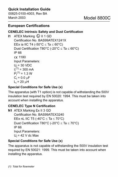
European Certifications
CENELEC Intrinsic Safety and Dust Certification
I1 ATEX Marking II 1 GD
Certification No. BAS99ATEX1241X
EEx ia IIC T4 (-50°C ≤ Ta ≤ 60°C)
Dust Certification T80°C (-20°C ≤ Ta ≤ 60°C)
IP 66
1180
Input Parameters:
Ui = 30 VDC
Ii(1) = 300 mA
Pi(1) = 1.3 W
Ci = 0.0 µF
Li = 20 µH
Special Conditions for Safe Use (x)
The apparatus (with T1 option) is not capable of withstanding the 500V
insulation test required by EN 50020: 1994. This must be taken into
account when installing the apparatus.
CENELEC Type N Certification
N1 ATEX Marking Ex II 3 GD
Certification No. BAS99ATEX3240
EEx nL IIC T5 (-40°C ≤ Ta ≤ 70°C)
Dust Certification T80°C (-20°C ≤ Ta ≤ 70°C)
IP 66
Input Parameters:
Ui = 42 V dc Max
Special Conditions for Safe Use (x)
The apparatus is not capable of withstanding the 500V insulation test
required by EN 50021: 1999. This must be taken into account when
installing the apparatus.
(1) Total for flowmeter
4003_revBA_qig.fm Page 26 Monday, March 31, 2003 7:51 AM

Quick Installation Guide00825-0100-4003, Rev BA
March 2003 Model 8800C
CENELEC Flame-Proof Certifications
ED Certification No. KEMA99ATEX3852X
ATEX Marking Remote Mount:
Transmitter: II 2(1) G
EEx d [ia]IIC T6 (Tamb= -50°C to 70°C)
Meter Body: II I G
EEx ia IIC T6 (Tamb= -50°C to 70°C)
ATEX Marking Integral Mount: Ex II 1/2 G
EEx d [ia] IIC T6 (Tamb= -50°C to 70°C)
Um = 250V
1180
Special Conditions
When installing the equipment particular precautions must be taken to
ensure taking account with the effect of the fluid temperature, that the
ambient temperature of the electrical parts of the apparatus is
comprised between -50 °C and 70 °C.
The remote mounted sensor may only be connected to the flowmeter
with the associated cable, supplied by the manufacturer.
4003_revBA_qig.fm Page 27 Monday, March 31, 2003 7:51 AM