Embed Size (px)
Citation preview
Model 727/731 POWERTEK
Model 727/731 Hydraulic Feed Chipper
Operation & Maintenance Manual
PowerTek Inc. P.O. Box 3
Lebanon, IN 46052 1-877-769-7835
5-09-12

SAFETY POWERTEK
WARNINGS
WARNING
WARNING TO PURCHASERS OF INTERNAL COMBUSTION ENGINE EQUIPPED MACHINERY OR DEVICES IN THE STATE OF
CALIFORNIA:
The equipment that you have purchased does not have a spark arrester muffler. If this equipment is to be used on any forest and brush covered land or grass
covered un-improved land in the state of California, the law requires that a spark arrester muffler be installed and be in effective working order. The spark arrester
must be attached to the exhaust system and comply with Section 4442 of the California Public Resources Code.
The engine exhaust from this equipment contains chemicals known to the State of
California to cause cancer, birth defects or other reproductive harm.
WARNING
This manual contains vital information for the safe use and efficient operation of this equipment. Carefully read this Operation Maintenance Manual before using this
equipment, as failure to adhere to the instructions could result in death, serious bodily injury and/or property damage.
This wood chipper is to be used only for chipping wood. Using this machine for any other purpose may cause injury and or property damage. Improper use of
this chipper will void the warranty.
1
TABLE OF CONTENTS POWERTEK SAFETY Warnings………………………1 Table of Contents…….………2 GENERAL OPERATING RULES General Operating Rules...….3 Safety Rules ..………………..4 Work Zone ...……………….5 INITIAL INSPECTION Engine .…………………….…6 Tires......……………………….6 Blades and Anvil ..…………..6 Loose Parts ………………….6 Freight Damage Inspection ..6 Battery…………………………6 Belts……………………………6 ON SITE SET UP Jack Stand…………………….7 Engine ………………………...7 Discharge Chute……………...7 OPERATION Starting Gas Engine………….8 Feeding Material……………...8 Cleaning Out Debris………….8 Stopping……………………….8 Emergency Stop Switch..……8 Starting Hydraulic Feed…… ..9 MAINTENANCE Engine..…..……………………10 Fuel..…..………………………10 Battery.......……………………10 Ignition....……………………...10 Cooling .…….…………………10 Air Cleaners…………………..11 Clutch………………………….11 Flywheel Bearings……………11 Wheel Bearings.……..……….11 Hour Meter…………………… 11 Discharge Chute.…..………...11 Drive Belts ..…………………..12 Chipper Blades ..……………..12 Anvil Adjustment……………...13 Maintenance Schedule ..…….14
SPECIFICATIONS General Specifications……….14 Performance Specifications ...14 HYDRAULIC SYSTEM MAINT. Cleaning Hydro System ...…..15 Hydraulic Oil…………………..15 Hydro Motor Shaft……………15 Hydraulic System Pressure…15 TROUBLE SHOOTING Diagnostic Procedures ..……16 Chipping Systems . …………17 Electronic Feed Control……...17 Setting Electronic Board……..18 Notes ……………………...…..19 ELECTRICAL SCHEMATIC 31 HP Vanguard Schematic…19 Electrical Schematic………….20 PARTS LIST Exploded View (General) …...21 Parts List (General)..…………22 Exploded View (Hydro)….…..23 Parts List (Hydro)….…………24 OWNERS INFORMATION Record Information ..………..25 WARRANTY Warranty Information …..…...26 Warranty Procedure………….26 Warranty Procedure (Cont.)…27
2
GENERAL OPERATING RULES POWERTEK PREPARATION RULE
1. Always inspect the chipper before and after each use to ensure safety and optimum performance.
2. Inspect the tires, safety chains, and towing hitch for
any malfunctions. Fix or replace any parts if found to be defective.
3. Check that the running lights and turn signals are
working properly. 4. Inspect that all decals are legible and in place.
Replace any defective decals. 5. Inspect the entire chipper for loose nuts and bolts.
Properly tighten if any are found. 6. Check all chamber bolts, blade bolts and anvil bolts.
Torque to the specified torque as mentioned later in the manual.
7. Remove and store flywheel safety pin before starting
the unit. 8. Grease all required and marked lubrication points. 9. Check all fluid levels in the engine. Fill if required. 10. Check all belts for wear, cracking or misalignment.
Replace if required. 11. Check all belts for proper tension. If loose retighten
to proper tension. 12. Inspect clutch shoes for wear. Replace if fiber pad is
worn from shoe. 13. Inspect knives and make sure they are sharp and
properly installed. If there are round edges or nicks that would not allow the blades to operate properly, re-sharpen them. If the blades are cracked or chipped replace them or they could cause serious injury or property damage. Torque all blade bolts to the proper torque.
14. Inspect that all hydraulic hoses are in good working order and are not cracked, worn, or leaking. 15. Check that all safety devices and switches are
functioning properly before use. 16. Always shut chipper engine off, allow flywheel to
stop turning, disconnect the spark plug wires and remove the key from the engine: before servicing any part of the chipper.
17. Always insert safety pin into the flywheel before
replacing or servicing blades and anvils. 18. Read the manual from cover to cover before using
chipper. 19. Know the capabilities and limitations of the chipper
before using it. 20. THINK SAFETY! TOWING 1. Before towing, inspect the safety latch on the hitch
coupler to make sure it is closed, latched, and pinned to prevent premature uncoupling of chipper hitch.
2. Safety chains should be crossed under the tongue of
the chipper and hooked securely to the frame of the towing vehicle.
3. Before towing be sure to rotate jack stand into the
transport position and make sure it is properly secured.
4. Make sure that the person who will be towing the
chipper has been properly instructed about local and state rules of the road and towing procedures.
5. DO NOT tow chipper faster than 45 MPH or chipper
may tip over when going around corners.
3
SAFETY POWERTEK
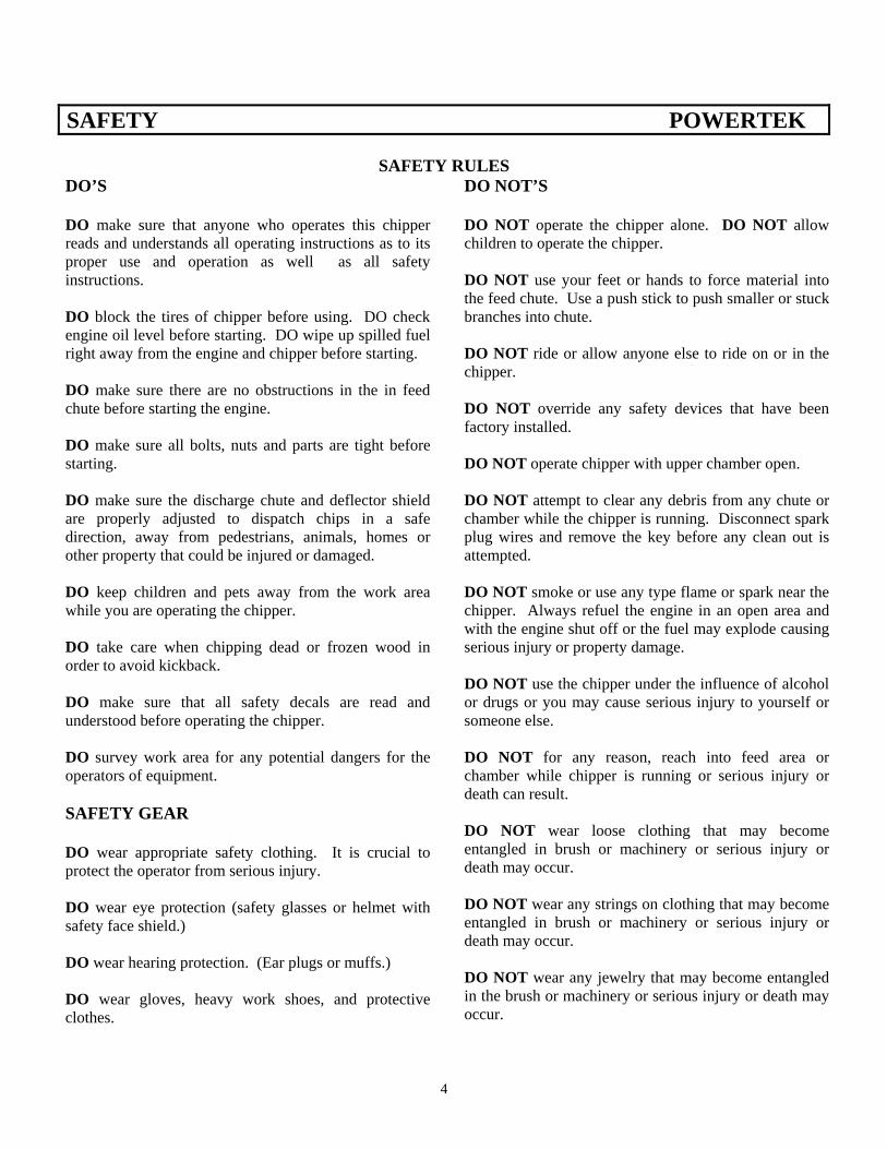
SAFETY RULES DO’S DO make sure that anyone who operates this chipper reads and understands all operating instructions as to its proper use and operation as well as all safety instructions. DO block the tires of chipper before using. DO check engine oil level before starting. DO wipe up spilled fuel right away from the engine and chipper before starting. DO make sure there are no obstructions in the in feed chute before starting the engine. DO make sure all bolts, nuts and parts are tight before starting. DO make sure the discharge chute and deflector shield are properly adjusted to dispatch chips in a safe direction, away from pedestrians, animals, homes or other property that could be injured or damaged. DO keep children and pets away from the work area while you are operating the chipper. DO take care when chipping dead or frozen wood in order to avoid kickback. DO make sure that all safety decals are read and understood before operating the chipper. DO survey work area for any potential dangers for the operators of equipment. SAFETY GEAR DO wear appropriate safety clothing. It is crucial to protect the operator from serious injury. DO wear eye protection (safety glasses or helmet with safety face shield.) DO wear hearing protection. (Ear plugs or muffs.) DO wear gloves, heavy work shoes, and protective clothes.
DO NOT’S DO NOT operate the chipper alone. DO NOT allow children to operate the chipper. DO NOT use your feet or hands to force material into the feed chute. Use a push stick to push smaller or stuck branches into chute. DO NOT ride or allow anyone else to ride on or in the chipper. DO NOT override any safety devices that have been factory installed. DO NOT operate chipper with upper chamber open. DO NOT attempt to clear any debris from any chute or chamber while the chipper is running. Disconnect spark plug wires and remove the key before any clean out is attempted. DO NOT smoke or use any type flame or spark near the chipper. Always refuel the engine in an open area and with the engine shut off or the fuel may explode causing serious injury or property damage. DO NOT use the chipper under the influence of alcohol or drugs or you may cause serious injury to yourself or someone else. DO NOT for any reason, reach into feed area or chamber while chipper is running or serious injury or death can result. DO NOT wear loose clothing that may become entangled in brush or machinery or serious injury or death may occur. DO NOT wear any strings on clothing that may become entangled in brush or machinery or serious injury or death may occur. DO NOT wear any jewelry that may become entangled in the brush or machinery or serious injury or death may occur.
4
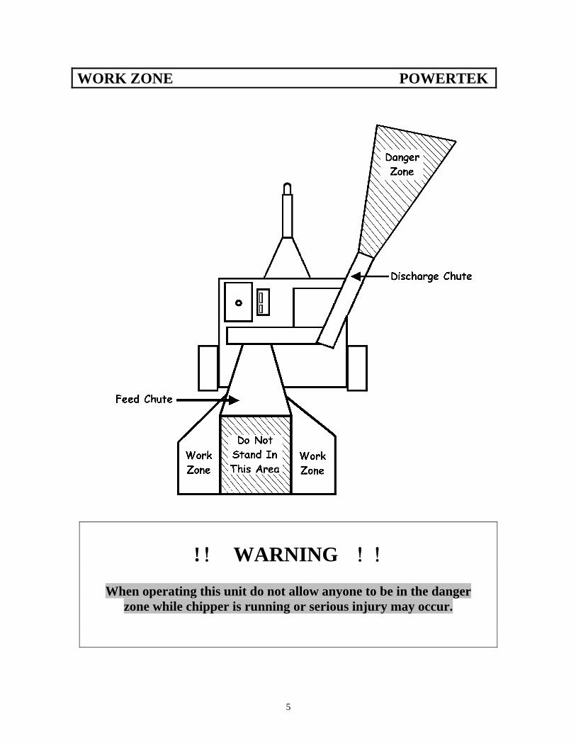
WORK ZONE POWERTEK
! ! WARNING ! !
When operating this unit do not allow anyone to be in the danger zone while chipper is running or serious injury may occur.
5
INITIAL INSPECTION POWERTEK Important! Upon receiving your chipper inspect and report any shipping damage to the carrier immediately. POWERTEK is not responsible for damage received during transport.
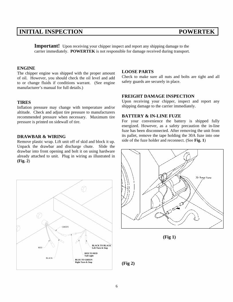
ENGINE The chipper engine was shipped with the proper amount of oil. However, you should check the oil level and add to or change fluids if conditions warrant. (See engine manufacturer’s manual for full details.) TIRES Inflation pressure may change with temperature and/or altitude. Check and adjust tire pressure to manufacturers recommended pressure when necessary. Maximum tire pressure is printed on sidewall of tire. DRAWBAR & WIRING Remove plastic wrap. Lift unit off of skid and block it up. Unpack the drawbar and discharge chute. Slide the drawbar into front opening and bolt it on using hardware already attached to unit. Plug in wiring as illustrated in (Fig. 2)
LOOSE PARTS Check to make sure all nuts and bolts are tight and all safety guards are securely in place. FREIGHT DAMAGE INSPECTION Upon receiving your chipper, inspect and report any shipping damage to the carrier immediately. BATTERY & IN-LINE FUZE For your convenience the battery is shipped fully energized. However, as a safety precaution the in-line fuze has been disconnected. After removing the unit from its pallet, remove the tape holding the 30A fuze into one side of the fuze holder and reconnect. (See Fig. 1)
BLACK TO BLACKLeft Turn & Stop
RED TO REDTail Light
BLUE TO GREENRight Turn & Stop
GREEN
(Fig 1) RED
BLACK
(Fig 2)
6
ON SITE SETUP POWERTEK
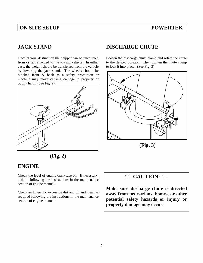
JACK STAND Once at your destination the chipper can be uncoupled from or left attached to the towing vehicle. In either case, the weight should be transferred from the vehicle by lowering the jack stand. The wheels should be blocked front & back as a safety precaution or machine may move causing damage to property or bodily harm. (See Fig. 2) (Fig. 2) ENGINE Check the level of engine crankcase oil. If necessary, add oil following the instructions in the maintenance section of engine manual. Check air filters for excessive dirt and oil and clean as required following the instructions in the maintenance section of engine manual.
DISCHARGE CHUTE Loosen the discharge chute clamp and rotate the chute to the desired position. Then tighten the chute clamp to lock it into place. (See Fig. 3) (Fig. 3)
! ! CAUTION: ! ! Make sure discharge chute is directed away from pedestrians, homes, or other potential safety hazards or injury or property damage may occur.
7
OPERATION POWERTEK
STARTING GAS ENGINE Set the throttle to idle speed. If the engine is cold set the choke, then turn the key to “START” position. If the engine does not start within 10 seconds allow a 60 second cool down period between attempts. When the engine starts let the key return to “RUN” position. Allow the engine to warm up at an idle speed, for 30 seconds then open the throttle. As the centrifugal clutch engages the flywheel will gradually come up to speed, the process should take 30-35 seconds. Run the engine at full RPMS. Important! If engine is allowed to idle for long periods, clutch damage will occur. FEEDING MATERIAL When feeding material into the hopper avoid pieces larger than 7” in diameter or limbs that are not easily handled. Stand to either side of the intake and feed limbs and branches large end first. If brush tends to hang in hopper alternate with small branches and limbs, do not attempt to push brush into the cutter by hand. If the flywheel speed slows, stop feeding until unit regains momentum. If speed is not regained shut the unit down by putting feed bar in neutral and turning key to the off position and inspect for clogging in the chute and flywheel chambers as described in following section. Also check the automatic feed control system to see if it is operating properly. CLEARING OUT DEBRIS
! ! WARNING ! ! Always shut down the unit and wait for all moving parts to fully stop before clearing or adjusting the discharge chute, flywheel or feedbox. Remove key from engine before clearing machine and remove wires from spark plug.
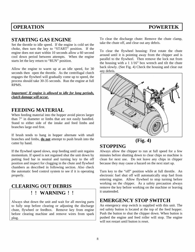
To clear the discharge chute: Remove the chute clamp, take the chute off, and clear out any debris. To clear the flywheel housing: First rotate the chute around until it is pointing away from the chipper and is parallel to the flywheel. Then remove the lock nut from the housing with a 1 1/16” box wrench and tilt the chute back slowly. (See Fig. 4) Check the housing and clear out any debris. (Fig. 4) STOPPING Always allow the chipper to run at full speed for a few minutes before shutting down to clear chips so machine is clean for next use. Do not leave any chips in chipper because they may cause a hazard on the next start up. Turn key to the “off” position while at full throttle. An electronic fuel shut off will automatically stop fuel from entering engine. Allow flywheel to stop turning before working on the chipper. As a safety precaution always remove the key before working on the machine or leaving it unattended. EMERGENCY STOP SWITCH An emergency stop switch is supplied with this unit. The red safety button is located at the top of the feed hopper. Push the button to shut the chipper down. When button is pushed the engine and feed roller will stop. The engine will not restart until button is reset.
8
OPERATION POWERTEK
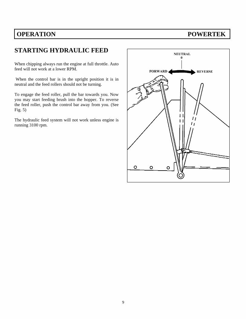
STARTING HYDRAULIC FEED When chipping always run the engine at full throttle. Auto feed will not work at a lower RPM. When the control bar is in the upright position it is in neutral and the feed rollers should not be turning. To engage the feed roller, pull the bar towards you. Now you may start feeding brush into the hopper. To reverse the feed roller, push the control bar away from you. (See Fig. 5) The hydraulic feed system will not work unless engine is running 3100 rpm.
(Fig. 5)
9
MAINTENANCE POWERTEK
ENGINE Check engine crankcase oil before each start. Make sure unit is filled with proper type and quantity of oil. Refer to engine manufacturers manual. Use high-quality detergent oil of API service class SF. Viscosity should be the same as oil currently in engine. To check oil, park unit on a level surface and allow oil time to drain into sump. Wipe dirt and debris from around fill cap and tube. Remove the dipstick and wipe clean. Return the dipstick fully into the tube. Pull it out again and check the fluid level registering on the stick. If necessary add oil to keep it in the engine’s operating range. In a new engine oil should be replaced after the first 5 hours if operation. For subsequent changes see engine manual. For best results drain oil when engine is warm. Remove the oil drain plug and dipstick. Allow oil to drain into a clean resealable container to facilitate recycling. Reinstall drain plug and fill to the “F” mark with the appropriate type of oil. See manufacturer’s specifications. Discard oil according to local codes FUEL For best results, use regular grade unleaded gasoline with octane rating of 87 or higher. When refueling do not overfill the tank, leave room for expansion. Due to it’s extreme flammability never add gasoline to a hot or running engine.
WARNING
Do not attempt to perform any maintenance procedures while engine or any other parts are in motion or while keys are in the ignition. Always remove wires from spark plugs or serious injury may occur.
BATTERY Each week or every 25 hours of operation check the electrolyte level of each battery cell. If a cell is low add distilled water to bring it up to the level indicator. If battery is sealed disregard this instruction. When replacing or recharging the battery use extreme care to avoid shorting between positive and negative terminals. To reduce risk of accidental shorting, disconnect the negative cable first when removing and reconnect it last when installing. IGNITION The gas engine is equipped with a electronic ignition system which requires very little maintenance. However, every 100 hours of operation the spark plug should be removed for inspection. Before removing, clean the area around the plug to prevent dirt and debris from falling into the cylinder. Remove and check for fouling, cracked porcelain, or incorrect electrode gap. If necessary replace the plug with manufacturer recommended plug and gap as needed. COOLING To prevent overheating and excessive wear, cooling fins should be cleaned every 25 hours or sooner if plugged. Fins can be cleaned by removing cooling shrouds and scraping away dirt and matted material. It is important to reinstall shrouds to insure proper airflow.
10
MAINTENANCE POWERTEK AIR CLEANERS Combustion air is supplied to the engine via a high-density air cleaner element and its surrounding precleaner. To ensure a sufficient air supply to the carburetor, remove and rinse the precleaner every 25 hours of operation. Check engine manual. Every 25 operating hours inspect the paper element while cleaning the prefilter. Gently tap the flat side of the paper element to dislodge surface dirt. If unit is excessively dirty, bent, or damaged replace element. Re-install both paper filters and secure.
(Fig. 6) WHEEL BEARINGS To prevent wheel bearings from burning out or locking up during transport, check and repack wheel bearings every 3 months. HOUR METER The meter is fully automatic with a display that may be read at all times, whether the engine is on or off. During running times, engine RPM is shown; after shut down, accumulated running time is shown. After 25 hours of running time, the meter will automatically blink as a signal for oil change. It will continue to blink for a (2) hour period of accumulated running time (ie., 25 to 27 hours). The next alert will automatically appear in 25 hours. No re-set is required.
DISCHARGE CHUTE If the discharge chute becomes difficult to rotate, grease at the fitting on the underside of the chute base do not over grease or chute will collect dirt. (Fig. 7)
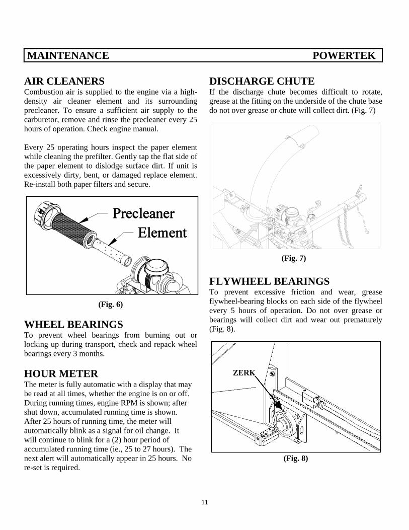
(Fig. 7) FLYWHEEL BEARINGS To prevent excessive friction and wear, grease flywheel-bearing blocks on each side of the flywheel every 5 hours of operation. Do not over grease or bearings will collect dirt and wear out prematurely (Fig. 8).
(Fig. 8)
11
MAINTENANCE POWERTEK
(Fig. 9) DRIVE BELTS The flywheel is driven by belts directly from the clutch. The belt must be kept properly tensioned. When properly tensioned, the belts should give a 3/8” deflection under fifteen lbs. of pressure (approx.) at the center span. To adjust belt tension, loosen the four engine sled bolts. Loosen lock nuts on the two tension bolts and adjust the bolts equally to keep the clutch and flywheel pulleys aligned. When the correct tension is achieved secure the lock nuts and mounting bolts. If the belts are excessively worn or can no longer be adjusted to the proper tension they must be replaced. It is extremely important to replace belts in matched sets to ensure uniform power transfer between engine and the flywheel. To replace belts follow the belt tensioning procedure. As stated below.
(Fig. 10) After loosening tension bolts lock nuts, unscrew bolts and slide engine towards the flywheel until belts can be removed. Install new belts then finish tensioning procedure.
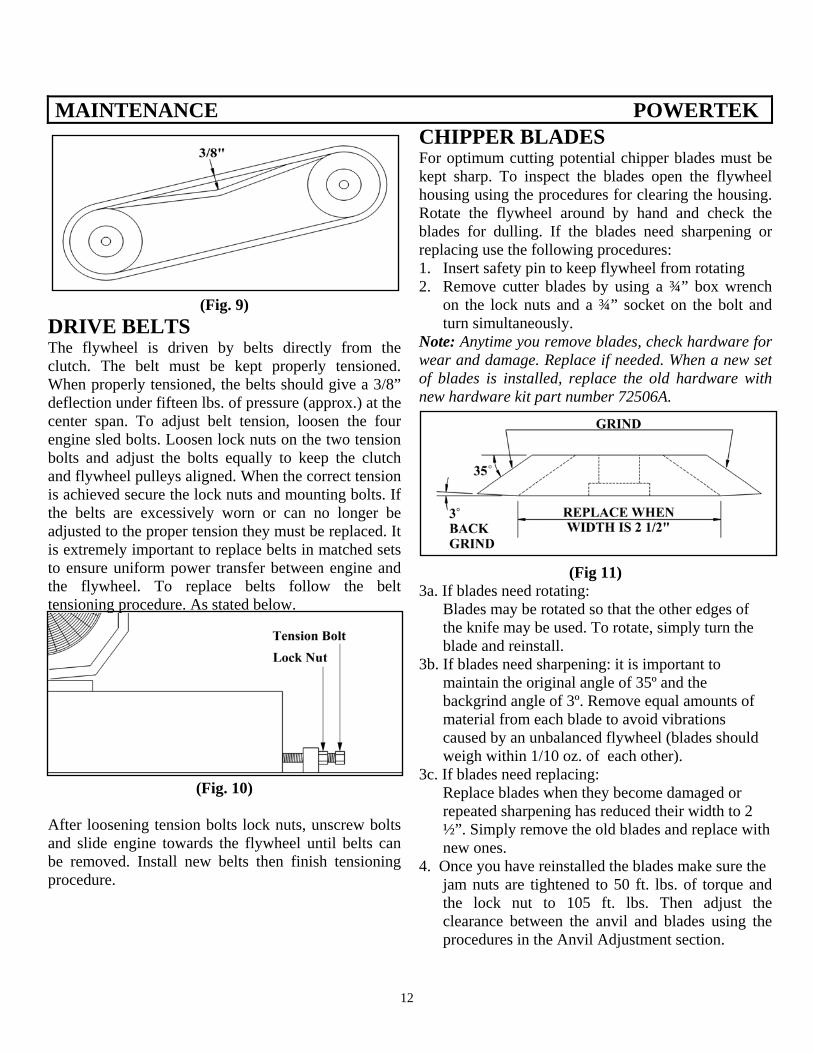
CHIPPER BLADES For optimum cutting potential chipper blades must be kept sharp. To inspect the blades open the flywheel housing using the procedures for clearing the housing. Rotate the flywheel around by hand and check the blades for dulling. If the blades need sharpening or replacing use the following procedures: 1. Insert safety pin to keep flywheel from rotating 2. Remove cutter blades by using a ¾” box wrench
on the lock nuts and a ¾” socket on the bolt and turn simultaneously.
Note: Anytime you remove blades, check hardware for wear and damage. Replace if needed. When a new set of blades is installed, replace the old hardware with new hardware kit part number 72506A.
(Fig 11) 3a. If blades need rotating: Blades may be rotated so that the other edges of the knife may be used. To rotate, simply turn the blade and reinstall. 3b. If blades need sharpening: it is important to maintain the original angle of 35º and the backgrind angle of 3º. Remove equal amounts of material from each blade to avoid vibrations caused by an unbalanced flywheel (blades should weigh within 1/10 oz. of each other). 3c. If blades need replacing: Replace blades when they become damaged or repeated sharpening has reduced their width to 2 ½”. Simply remove the old blades and replace with new ones. 4. Once you have reinstalled the blades make sure the
jam nuts are tightened to 50 ft. lbs. of torque and the lock nut to 105 ft. lbs. Then adjust the clearance between the anvil and blades using the procedures in the Anvil Adjustment section.
12
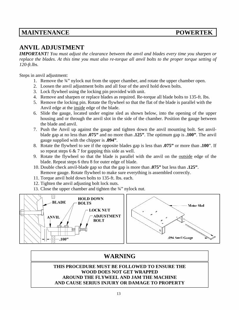
MAINTENANCE POWERTEK ANVIL ADJUSTMENT IMPORTANT! You must adjust the clearance between the anvil and blades every time you sharpen or replace the blades. At this time you must also re-torque all anvil bolts to the proper torque setting of 120-ft.lbs. Steps in anvil adjustment:
1. Remove the ¾” nylock nut from the upper chamber, and rotate the upper chamber open. 2. Loosen the anvil adjustment bolts and all four of the anvil hold down bolts. 3. Lock flywheel using the locking pin provided with unit. 4. Remove and sharpen or replace blades as required. Re-torque all blade bolts to 135-ft. lbs. 5. Remove the locking pin. Rotate the flywheel so that the flat of the blade is parallel with the
Anvil edge at the inside edge of the blade. 6. Slide the gauge, located under engine sled as shown below, into the opening of the upper
housing and or through the anvil slot in the side of the chamber. Position the gauge between the blade and anvil.
7. Push the Anvil up against the gauge and tighten down the anvil mounting bolt. Set anvil-blade gap at no less than .075” and no more than .125”. The optimum gap is .100”. The anvil gauge supplied with the chipper is .094”.
8. Rotate the flywheel to see if the opposite blades gap is less than .075” or more than .100”. If so repeat steps 6 & 7 for gapping this side as well.
9. Rotate the flywheel so that the blade is parallel with the anvil on the outside edge of the blade. Repeat steps 6 thru 8 for outer edge of blade.
10. Double check anvil-blade gap so that the gap is more than .075” but less than .125”. Remove gauge. Rotate flywheel to make sure everything is assembled correctly.
11. Torque anvil hold down bolts to 135-ft. lbs. each. 12. Tighten the anvil adjusting bolt lock nuts. 13. Close the upper chamber and tighten the ¾” nylock nut.
WARNING THIS PROCEDURE MUST BE FOLLOWED TO ENSURE THE
WOOD DOES NOT GET WRAPPED AROUND THE FLYWEEL AND JAM THE MACHINE
AND CAUSE SERIUS INJURY OR DAMAGE TO PROPERTY
13
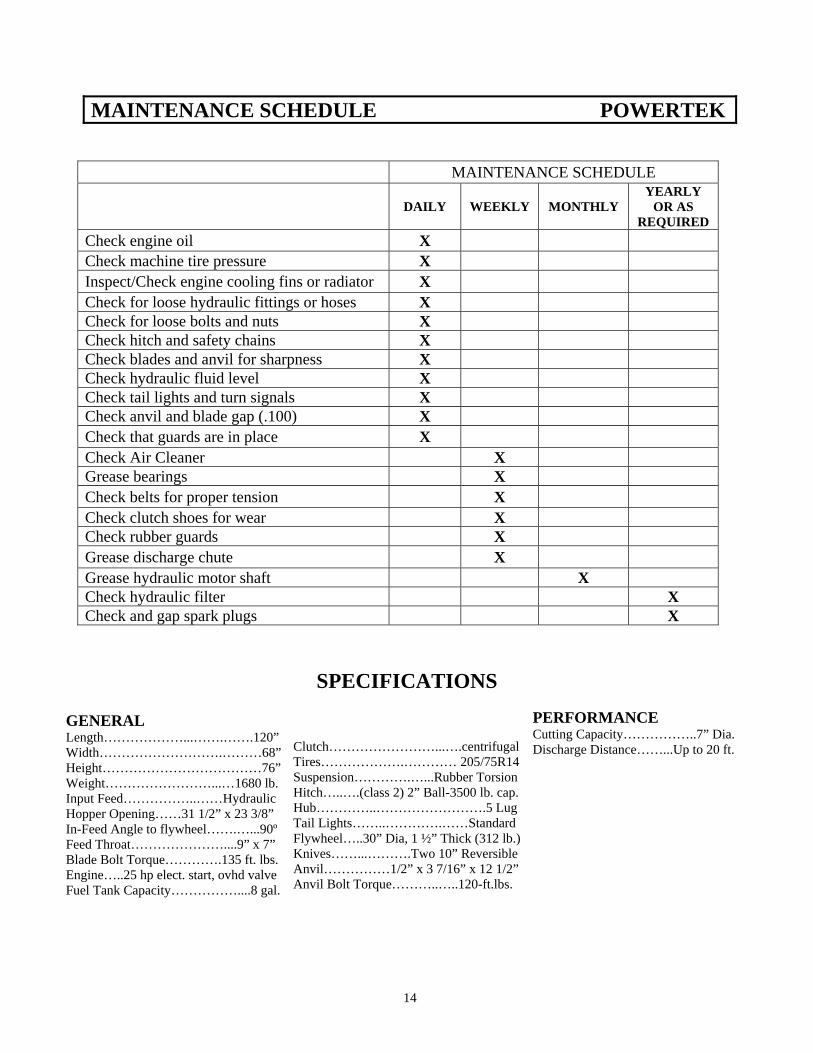
MAINTENANCE SCHEDULE POWERTEK
MAINTENANCE SCHEDULE
DAILY WEEKLY MONTHLY YEARLY
OR AS REQUIRED
Check engine oil X Check machine tire pressure X Inspect/Check engine cooling fins or radiator X Check for loose hydraulic fittings or hoses X Check for loose bolts and nuts X Check hitch and safety chains X Check blades and anvil for sharpness X Check hydraulic fluid level X Check tail lights and turn signals X Check anvil and blade gap (.100) X Check that guards are in place X Check Air Cleaner X Grease bearings X Check belts for proper tension X Check clutch shoes for wear X Check rubber guards X Grease discharge chute X Grease hydraulic motor shaft X Check hydraulic filter X Check and gap spark plugs X
SPECIFICATIONS GENERAL Length………………...…….…….120” Width……………………….………68” Height………………………………76” Weight……………………...…1680 lb. Input Feed……………..……Hydraulic Hopper Opening……31 1/2” x 23 3/8” In-Feed Angle to flywheel…….…...90º Feed Throat…………………....9” x 7” Blade Bolt Torque………….135 ft. lbs. Engine…..25 hp elect. start, ovhd valve Fuel Tank Capacity……………....8 gal.
Clutch……………………...….centrifugal Tires……………….………… 205/75R14 Suspension………….…...Rubber Torsion Hitch…..….(class 2) 2” Ball-3500 lb. cap. Hub…………..…………………….5 Lug Tail Lights……..………….……Standard Flywheel…..30” Dia, 1 ½” Thick (312 lb.) Knives……...……….Two 10” Reversible Anvil……………1/2” x 3 7/16” x 12 1/2” Anvil Bolt Torque………..…..120-ft.lbs.
PERFORMANCE Cutting Capacity……………..7” Dia. Discharge Distance……...Up to 20 ft.
14
HYDRAULIC SYSTEM MAINTENANCE POWERTEK
CLEANING HYDRAULIC SYSTEM Keep the system clean. The hydraulic pump will last longer with few repairs if the system is kept clean. Keep the oil clean. Debris and dirt in the oil can clog the relief valves and other parts resulting in poor pump performance. Replace the hydraulic oil filter after the first 100 hours of operation and then every 200 hours of operation thereafter. The canister is replaceable. HYDRAULIC OIL Do not operate the chipper if the hydraulic oil level is too low. This will cause the pump to overheat. Use a hydraulic oil equivalent to Dextron III ATF. Oil level is 1” from top of reservoir. HYDRAULIC MOTOR SHAFT The spline on the end of the hydraulic motor shaft needs to be greased about every 100 hours of operation. Remove the motor and apply 3-4 squirts from a grease gun inside the shaft then replace the motor.
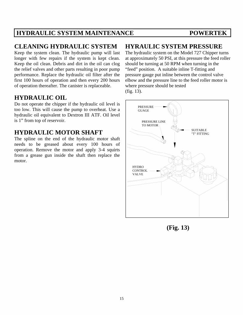
HYRAULIC SYSTEM PRESSURE The hydraulic system on the Model 727 Chipper turns at approximately 50 PSI, at this pressure the feed roller should be turning at 50 RPM when turning in the “feed” position. A suitable inline T-fitting and pressure gauge put inline between the control valve elbow and the pressure line to the feed roller motor is where pressure should be tested (fig. 13).
PRESSUREGUAGE
SUITABLE"T" FITTING
HYDROCONTROLVALVE
PRESSURE LINETO MOTOR
(Fig. 13)
15
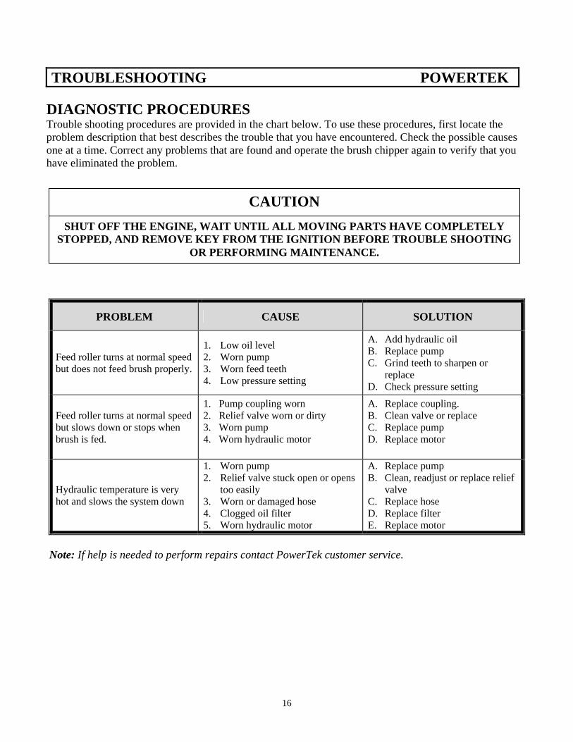
TROUBLESHOOTING POWERTEK
DIAGNOSTIC PROCEDURES Trouble shooting procedures are provided in the chart below. To use these procedures, first locate the problem description that best describes the trouble that you have encountered. Check the possible causes one at a time. Correct any problems that are found and operate the brush chipper again to verify that you have eliminated the problem.
CAUTION
SHUT OFF THE ENGINE, WAIT UNTIL ALL MOVING PARTS HAVE COMPLETELY STOPPED, AND REMOVE KEY FROM THE IGNITION BEFORE TROUBLE SHOOTING
OR PERFORMING MAINTENANCE.
PROBLEM CAUSE SOLUTION
Feed roller turns at normal speed but does not feed brush properly.
1. Low oil level 2. Worn pump 3. Worn feed teeth 4. Low pressure setting
A. Add hydraulic oil B. Replace pump C. Grind teeth to sharpen or
replace D. Check pressure setting
Feed roller turns at normal speed but slows down or stops when brush is fed.
1. Pump coupling worn 2. Relief valve worn or dirty 3. Worn pump 4. Worn hydraulic motor
A. Replace coupling. B. Clean valve or replace C. Replace pump D. Replace motor
Hydraulic temperature is very hot and slows the system down
1. Worn pump 2. Relief valve stuck open or opens
too easily 3. Worn or damaged hose 4. Clogged oil filter 5. Worn hydraulic motor
A. Replace pump B. Clean, readjust or replace relief
valve C. Replace hose D. Replace filter E. Replace motor
Note: If help is needed to perform repairs contact PowerTek customer service.
16
TROUBLESHOOTING POWERTEK
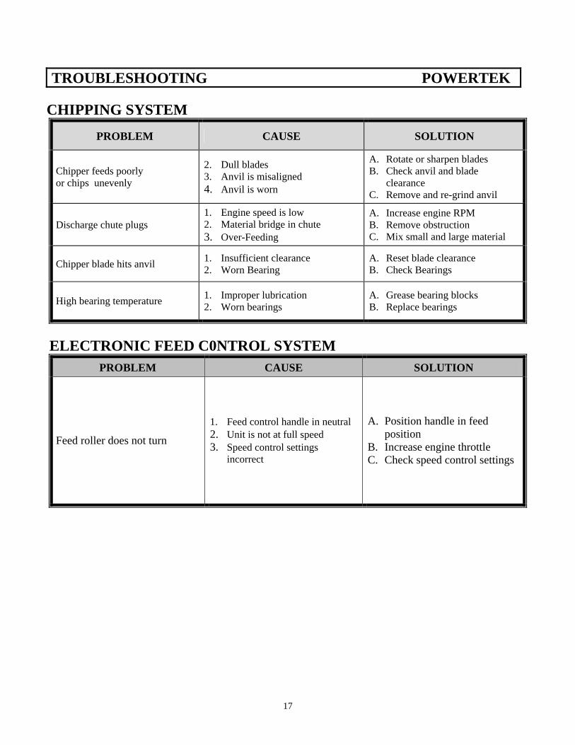
CHIPPING SYSTEM
PROBLEM CAUSE SOLUTION
Chipper feeds poorly or chips unevenly
2. Dull blades 3. Anvil is misaligned 4. Anvil is worn
A. Rotate or sharpen blades B. Check anvil and blade
clearance C. Remove and re-grind anvil
Discharge chute plugs 1. Engine speed is low 2. Material bridge in chute 3. Over-Feeding
A. Increase engine RPM B. Remove obstruction C. Mix small and large material
Chipper blade hits anvil 1. Insufficient clearance 2. Worn Bearing
A. Reset blade clearance B. Check Bearings
High bearing temperature 1. Improper lubrication 2. Worn bearings
A. Grease bearing blocks B. Replace bearings
ELECTRONIC FEED C0NTROL SYSTEM
PROBLEM CAUSE SOLUTION
Feed roller does not turn
1. Feed control handle in neutral 2. Unit is not at full speed 3. Speed control settings
incorrect
A. Position handle in feed position
B. Increase engine throttle C. Check speed control settings
17
TROUBLESHOOTING POWERTEK
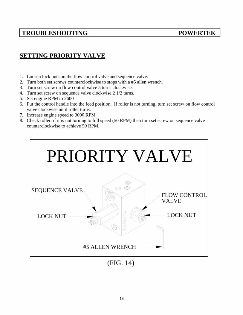
SETTING PRIORITY VALVE 1. Loosen lock nuts on the flow control valve and sequence valve. 2. Turn both set screws counterclockwise to stops with a #5 allen wrench. 3. Turn set screw on flow control valve 5 turns clockwise. 4. Turn set screw on sequence valve clockwise 2 1/2 turns. 5. Set engine RPM to 2600 6. Put the control handle into the feed position. If roller is not turning, turn set screw on flow control
valve clockwise until roller turns. 7. Increase engine speed to 3000 RPM 8. Check roller, if it is not turning to full speed (50 RPM) then turn set screw on sequence valve
counterclockwise to achieve 50 RPM.
FLOW CONTROLVALVE
SEQUENCE VALVE
LOCK NUTLOCK NUT
PRIORITY VALVE
#5 ALLEN WRENCH
(FIG. 14)
18
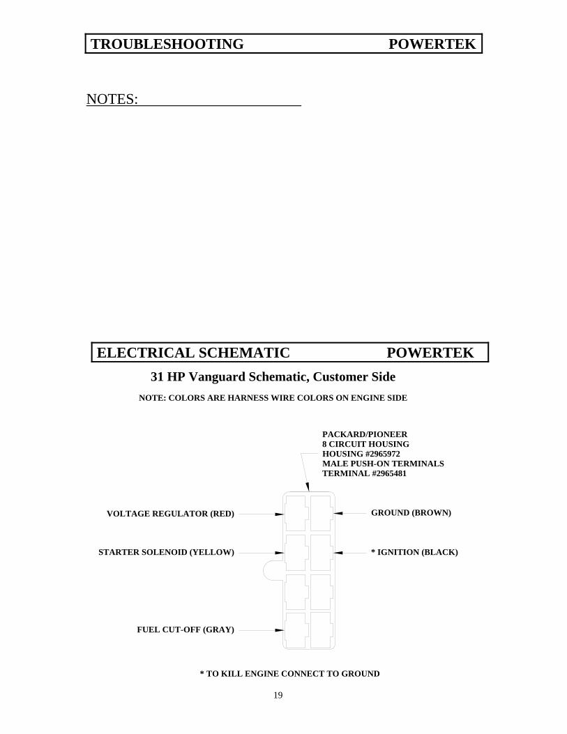
GROUND (BROWN)
* IGNITION (BLACK)
VOLTAGE REGULATOR (RED)
STARTER SOLENOID (YELLOW)
FUEL CUT-OFF (GRAY)
NOTE: COLORS ARE HARNESS WIRE COLORS ON ENGINE SIDE
PACKARD/PIONEER8 CIRCUIT HOUSINGHOUSING #2965972MALE PUSH-ON TERMINALSTERMINAL #2965481
31 HP Vanguard Schematic, Customer Side
* TO KILL ENGINE CONNECT TO GROUND
NOTES:
TROUBLESHOOTING POWERTEK
ELECTRICAL SCHEMATIC POWERTEK
19
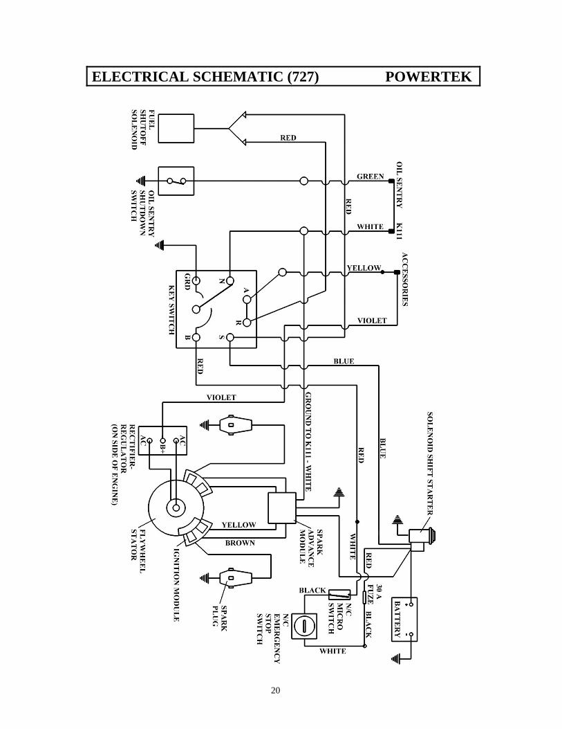
ELECTRICAL SCHEMATIC (727) POWERTEK
20
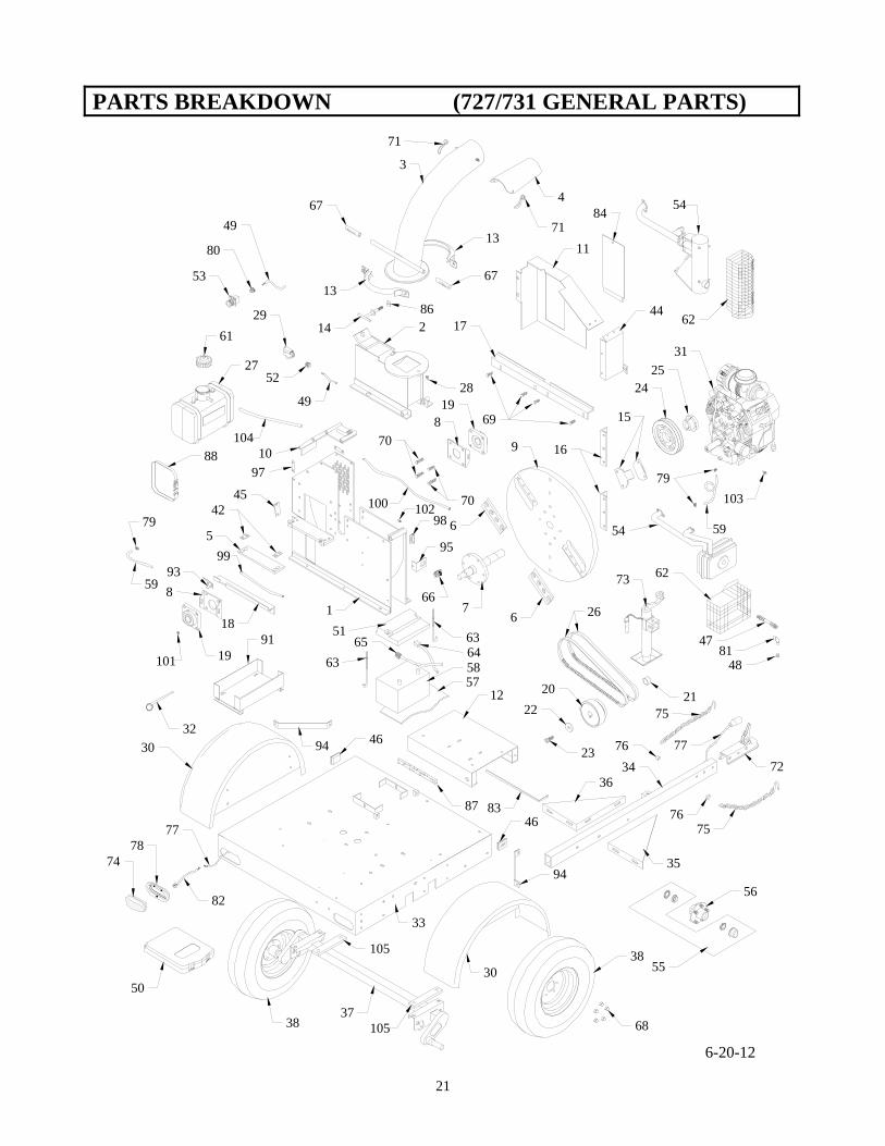
PARTS BREAKDOWN (727/731 GENERAL PARTS)
10
3
4
56
67
8
8
9
2
11
12
13
13
14
16
17
18
19
19
2022
23
26
28
31
32
33
34
35
36
3738
38
42
44
45
46
51 63
6364
65
67
67
68
72
73
7875
75
76
76
74
30
49
52
77
47
48
50
2425
15
55
56
57
77
58
71
71
29
59
6-20-12
61
80
53
49
6970
70
54
62
79
81
82
83
84
66
21
87
91
88
1
86
79
59
94
93
30
46
94
54
62
97
98
95
100
99
101
102103
27
104
105
105
21
Parts List (727/731 General Parts) Powertek
22
Key Part No. Description 1 72501 Lower Housing 2 72502 Upper Housing 3 72503 Discharge Chute 4 72504 Deflector, discharge chute 5 72505 Anvil 6 72506 Chipper Knife 7 72507 Flywheel Hub & Shaft Assembly 8 72508 Bearing Bracket 9 72509 Flywheel 10 72510 Removable Casing Assembly 11 72511 Pulley Guard thru s/n 62561 72647 Pulley Guard s/n 62562/up 12 72512 Motor Sled, Kohler 72672 Motor Sled, Vanguard 13 72513 Discharge Clamp Half 14 72514 T-Handle, Discharge Chute 16 72616 Impeller 17 72517 Angle Flange, Power Side 18 72518 Angle Flange, Feed Side 19 72519 Bearing 20 72520 Clutch thru s/n 62581 72649 Clutch s-n 62582/up 21 72521 Clutch Spacer thru s/n 62581 Only 22 72522 Clutch Retainer 23 72523 Clutch Retainer Bolt 24 72524 Pulley 25 72525 Pulley Bushing 26 72526 Belt 27 72527 Gas Tank, Includes Cap thru s/n 62581 72654 Gas Tank, Includes Cap s/n 62582 thru 62931 28807 Gas tank s/n 62932/up Cap not included 72710 Gas Tank, Cap Included s/n 62932/up 28 3122501 Grease Fitting 29 72529 Safety Switch 30 72530 Fender Assembly 31 72531 Engine, 25HP Kohler Elect. 72673 Engine 31HP B&S Vanguard 32 72532 Flywheel Safety Pin 33 72533 Trailer Frame 34 72534 Trailer Tongue 35 72535 Trailer Tongue Brace, RH 36 72536 Trailer Tongue Brace, LH 37 72537 Suspension Axle w/ Hub 38 72538 Wheel 42 72542 Anvil Support Spacer 44 72544 Pulley Guard Front thru s/n 62561 72648 Pulley Guard Front s/n 62562/up 45 72545 Gauge Cover 46 72646 Side Marker, Amber 47 72647 Oil Drain Tube, Kohler 72677 Oil Drain Tube, Vanguard 48 72548 Plug, Oil Drain, Kohler 49 72549 Wire Harness, Safety Switch 50 16339 Manual Pak 51 72551 Battery Hold Down Cap 52 72552 Cord Grip, Chipper 53 72553 Stop Switch 54 72554 Muffler Assembly, Kohler 72674 Muffler Assembly, Vanguard 55 72555 Bearing Kit 56 72556 Hub 57 72557 Battery Pad
Key Part No. Description 58 72558 Battery 59 72559 Fuel Line 61 72609 Gas Cap thru s/n 62581 16216 Gas Cap s/n 6282 thru 62931 28902 Gas Cap s/n 62932/up 72711 Gas Cap s/n- 62 72621 Muffler Guard 72685 Muffler Guard 31HP Vanguard 63 16211 J-Bolts, Battery Hold Down 64 72642 Positive Cable, Red 65 72643 Negative Cable, Black 66 16215 Hour Meter/Tach, thru s/n 62549 72646 Hour Meter/Tach, Flush Mount s/n 62550/up 67 45107 Hand Grip. 3/4" Handle 68 5001002 1/2" Lug Nut 69 5001225 1/2" x 1 1/2" Stud 70 5002516 1/2" x 2" Stud (bearings) 71 3751016 Handle Nut 72 51601 2" Ball Coupler 73 51602 Jack 74 72640A Recessed Tail Light 75 51624 Safety Chain 76 51625 Safety Chain Spacer 77 72697 Wiring Harness 78 72640B Grommet, Recessed Tail Light 79 28839 Fuel Line Clamps 80 72623 1/2" Romex Connector 81 72624 Fitting 90° 3/8 FP-3 Elbow 82 72640C Pigtail/Plug, Recessed Tail Light 83 72636 Anvil Gauge 84 72587 Guard Access Panel 86 45061 Nylon Washer 87 46219 Foam Seal, Anti-vibration 88 16233 Gas Tank Strap 62582/up 91 725338 Gas Tank Mount s/n 62585 thru 62931 72702 Gas Tank Mount s/n 62932/up 93 72680 Anti Wrap Angle 94 72681 Fender Brace 95 72701 Hour Meter Bracket 97 72682 Mount Tab Guard 98 72703 Grease Hose Bracket 99 72704 Grease Hose, 15" 100 72705 Grease Hose, 36" 101 72706 Fitting, 1/4-28 1/8" pipe 45° 102 72707 Fitting, 1/4-28 1/8" pipe straight 103 72717 Reducer Coupling, 1/4" X 1/8" 104 72718 Vent Line, 1/4" 105 72719 Axle Pad 51650 Decal, Danger Stop Engine 51656 Decal, Caution Safety Chains 51660 Decal, Cauttion Read Owners Man. 51662 Decal, Warning Flying Wood 51665 Decal, Warning Operator w/i 10ft 72595 Decal, Danger Feed from Side 72596 Decal, Danger Do Not Open.... 72597 Decal, Warning Torque Anvil 72598 Decal, Warning Do Not Sit-Ride 72599 Decal, Grease Fitting 51669 Decal, Powertek 162171 Float Assembly 3 & 6 Gal. Tank 162172 Pick-up Assembly 3 & 6 Gal. Tank 28907 Trailer Connector 8-13-12
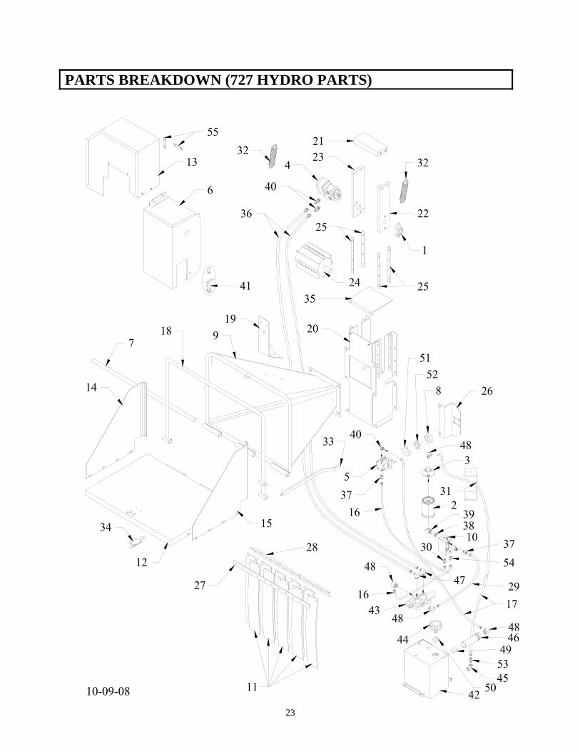
PARTS BREAKDOWN (727 HYDRO PARTS)
23
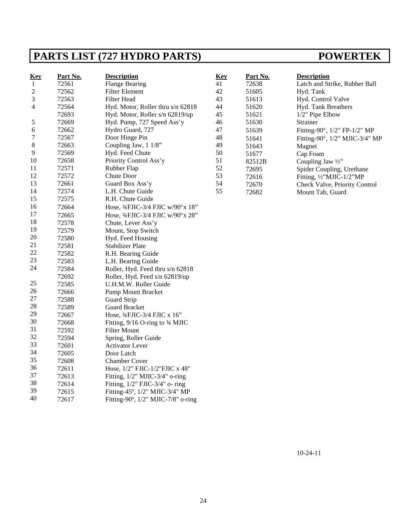
PARTS LIST (727 HYDRO PARTS) POWERTEK
Key 1 2 3 4 5 6 7 8 9 10 11 12 13 14 15 16 17 18 19 20 21 22 23 24 25 26 27 28 29 30 31 32 33 34 35 36 37 38 39 40
Part No. Description 72561 Flange Bearing 72562 Filter Element 72563 Filter Head 72564 Hyd. Motor, Roller thru s/n 62818 72693 Hyd. Motor, Roller s/n 62819/up 72669 Hyd. Pump, 727 Speed Ass’y 72662 Hydro Guard, 727 72567 Door Hinge Pin 72663 Coupling Jaw, 1 1/8” 72569 Hyd. Feed Chute 72658 Priority Control Ass’y 72571 Rubber Flap 72572 Chute Door 72661 Guard Box Ass’y 72574 L.H. Chute Guide 72575 R.H. Chute Guide 72664 Hose, ¾FJIC-3/4 FJIC w/90°x 18” 72665 Hose, ¾FJIC-3/4 FJIC w/90°x 28” 72578 Chute, Lever Ass’y 72579 Mount, Stop Switch 72580 Hyd. Feed Housing 72581 Stabilizer Plate 72582 R.H. Bearing Guide 72583 L.H. Bearing Guide 72584 Roller, Hyd. Feed thru s/n 62818 72692 Roller, Hyd. Feed s/n 62819/up 72585 U.H.M.W. Roller Guide 72666 Pump Mount Bracket 72588 Guard Strip 72589 Guard Bracket 72667 Hose, ¾FJIC-3/4 FJIC x 16” 72668 Fitting, 9/16 O-ring to ¾ MJIC 72592 Filter Mount 72594 Spring, Roller Guide 72601 Activator Lever 72605 Door Latch 72608 Chamber Cover 72611 Hose, 1/2" FJIC-1/2"FJIC x 48" 72613 Fitting, 1/2" MJIC-3/4" o-ring 72614 Fitting, 1/2" FJIC-3/4" o- ring 72615 Fitting-45º, 1/2" MJIC-3/4" MP 72617 Fitting-90º, 1/2" MJIC-7/8" o-ring
Key 41 42 43 44 45 46 47 48 49 50 51 52 53 54 55
Part No. Description 72638 Latch and Strike, Rubber Ball 51605 Hyd. Tank 51613 Hyd. Control Valve 51620 Hyd. Tank Breathers 51621 1/2" Pipe Elbow 51630 Strainer 51639 Fitting-90°, 1/2" FP-1/2" MP 51641 Fitting-90°, 1/2" MJIC-3/4" MP 51643 Magnet 51677 Cap Foam 82512B Coupling Jaw ½” 72695 Spider Coupling, Urethane 72616 Fitting, ½”MJIC-1/2”MP 72670 Check Valve, Priority Control 72682 Mount Tab, Guard
10-24-11
24
OWNERS INFORMATION POWERTEK
Additional or replacement manuals may be obtained from your local PowerTek distributor. When chipper is received, complete the following record. SERIAL NUMBER: ____________________________ DATE OF PURCHASE: _________________________ WHERE PURCHASED: _________________________ Always mention the machine's model and serial number when ordering or writing about parts. For convenience in ordering, parts are listed by part number, description and quantity. Always supply part number and complete description when ordering. When assemblies can be used, order them to save time assembling individual parts. Prior arrangements must be made before returning chipper for warranty service. Service calls should be directed to Customer Service at 1-877-769-7835. To insure correct and prompt shipment of parts, always provide the following information when ordering. 1. Quantity of each part wanted 2. Part number and description 3. Model and serial number of chipper 4. Preferred method of shipment: by mail, UPS, or airfreight
25
WARRANTY POWERTEK
WARRANTY INFORMATION Each new product is warranted against manufacturing defects in workmanship and/or materials under normal use and service for a period of 12 months from the date of delivery of the product to the original purchaser. PowerTek Inc.'s obligation under this warranty shall be limited to the replacement to the original purchaser of any part which, as delivered to the original purchase, and upon PowerTek Inc.'s examination, is shown to PowerTek Inc.'s satisfaction, to be defective due to faulty workmanship or materials at the factory. This warranty does not apply to damage in transit, damage caused by user misuse, negligence, accident, normal wear, or alterations or repairs done outside the factory and/or authorized service stations as determined by PowerTek Inc. All parts claimed to be defective must be returned to PowerTek Inc.'s factory for inspection, repair or replacement, with all transportation or mailing charges prepaid. It is the exclusive responsibility of the purchaser to bear the transportation or mailing charges on any warranty claim. This warranty specifically excludes engines or batteries, which are warranted separately by their respective manufacturers, all claims for defective batteries, engines or engine parts must be made in accordance with the battery and /or engine manufacturer's warranty. This warranty also specifically excludes costs of regular maintenance and replacement of service items such as belts, hoses, blades, and similar items. PowerTek Inc. reserves the right to make changes upon PowerTek Inc.'s products without imposing any obligation upon PowerTek Inc. to install the same on a product manufactured prior to the change. PowerTek Inc. makes no other warranties, representations or promises other than those set forth herein. PowerTek Inc. specifically disclaims any and all implied warranties of fitness for particular purpose and merchantability. The remedies available to a distributor, dealer, and/or purchaser in connection with PowerTek Inc.'s warranty are set forth above. In no event will PowerTek Inc. be liable for special, incidental or consequential damages.
POWERTEK INC. WARRANTY PROCEDURE A. All requests for warranty must have approval from PowerTek Inc. and/or distributor before work starts,
or the warranty claim will be denied. B. All requests for warranty must be made on an OPEI or equivalent warranty claim form. This form is
available from PowerTek Inc. or an authorized PowerTek Inc. distributor or dealer on a no charge basis. C. It is the responsibility of the distributor or dealer to complete the form warranty claim and submit it to PowerTek Inc..
1. The form must be filled out completely. Claims received without serial numbers, model numbers, replacement part numbers, purchase dates, repair dates, purchaser's correct address, signature or other information requested by PowerTek Inc. shall be denied. 2. Warranty claims that are illegible will be returned without service. Please type or print in black ink. 3. PowerTek Inc.'s warranty makes no allowance for the time spent to fill out the warranty claim. Any such claim will be denied.
26
WARRANTY POWERTEK
WARRANTY PROCEDURE (CONTINUED) 4. All parts shall be retained and tagged for a period of 60 days or until credit is issued.
5. The factory my request parts to be returned for examination or analysis. These parts shall be sent by prepaid freight to PowerTek Inc. Returns sent freight collect, without express, written permission from PowerTek Inc. shall not be accepted.
6. It is the responsibility of the dealer to review the claim and to comply fully with all procedures set forth herein. Failure to do so shall result in the denial of the warranty claim. D. Any warranty payments by PowerTek Inc. will be paid by credit memo to the distributor, dealer. E. All warranty claims, which are denied, will be returned with a reason for denial. F. Labor Allowance. 1. The warranty labor rate is $35.00 per hour. 2. The actual time is divided into tenths of an hour. The warranty form should show the time to the nearest tenth of an hour. 3. Labor credit is based on the actual time required only to make the repair. G. Items not covered by warranty.
1. Mileage and transportation costs of any kind. All warranty is "Bench Work" only. The warranty specifically states that any transportation charges in connection with a warranty repair is the exclusive responsibility of the purchaser.
2. Postage, delivery, telephone calls or similar communications. 3. Normal maintenance or adjustments. This includes set up and service. 4. Battery, engine or engine parts. Warranty on batteries, engines, engine parts or other vender parts is covered by the component manufacturer's warranty and must be handle by that component manufacturer's representative. 5. Failure caused by neglect, normal wear, or abuse. PowerTek Inc. depends on its distributor and dealer network to accurately determine when such conditions occur. 6. Any alteration of the original design of the unit or the use of unauthorized or non-PowerTek Inc. parts. Any claim submitted containing such unauthorized alteration repairs shall be rejected. 7. Freight or transportation damage. All such damage is the responsibility of the carrier and any claim for damages must be made with the carrier. 8. Compound or repeat warranties caused by negligent/improper repair. 9. Any claim for warranty where the date of repair exceeds sixty (60) days from the submission of the warranty claim. 10. Any claim for warranty on the entire unit. 11. Warranty claims involving oils or fluids of any kind. 12. Any warranty claims for leaking, punctured, blown, flat, or otherwise damaged tires on units that have been placed in service. 13. Lost time, lost rentals, lost profits, or other economic loss due to warranty work. Voluntary cooperation with the entire warranty procedure will make the program work better for both the purchaser and PowerTek Inc.
27