Embed Size (px)
Citation preview
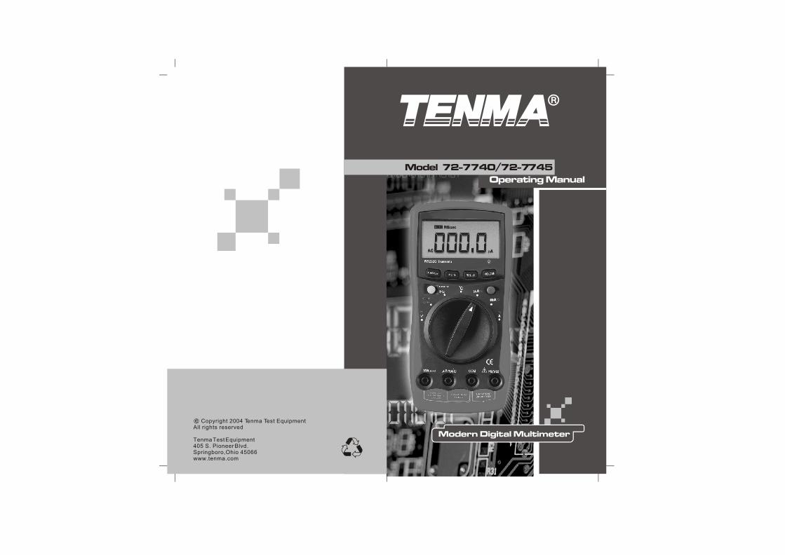
Model 72-7740/72-7745
Copyright 2004 Tenma Test EquipmentAll rights reserved
Tenma Test Equipment405 S. Pioneer Blvd.Springboro,Ohio 45066www.tenma.com
34456789
11
1212
1415 16171819 2021 222224242525252526
27272728
Unpacking Inspection
Rules For Safe Operation
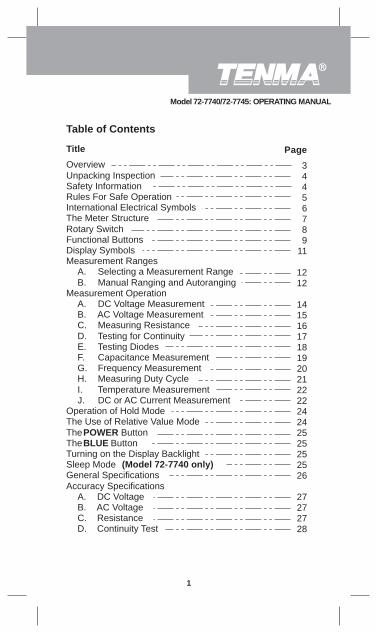
Title Page
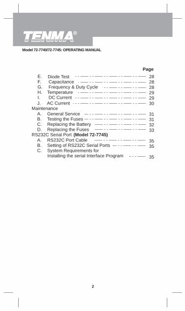
Table of Contents
1
D. Continuity Test
International Electrical Symbols
AC Voltage Measurement
Capacitance Measurement
The Use of Relative Value Mode
The Meter Structure
Turning on the Display Backlight
General Specifications
Resistance
Overview
Safety Information
Rotary SwitchFunctional ButtonsDisplay SymbolsMeasurement Ranges
A.B.
Measurement OperationA.B.C.D. Testing for ContinuityE.F.G.H.I. Temperature MeasurementJ.
Operation of Hold Mode
The POWER ButtonThe BLUE Button
Sleep Mode (Model 72-7740 only)
Accuracy SpecificationsA. DC VoltageB. AC VoltageC.
Selecting a Measurement Range Manual Ranging and Autoranging
DC Voltage Measurement
Measuring Resistance
Frequency Measurement
DC or AC Current Measurement
Testing Diodes
Measuring Duty Cycle
Model 72-7740/72-7745: OPERATING MANUAL
Capacitance Frequency & Duty Cycle
DC Current
2828282929 30
31313233
3535
35
Page
2
J. AC CurrentMaintenance
A. General ServiceB. Testing the FusesC. Replacing the BatteryD. Replacing the Fuses
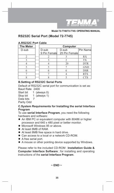
RS232C Serial Port (Model 72-7745)A. RS232C Port CableB. Setting of RS232C Serial PortsC. System Requirements for
Installing the serial Interface Program
Diode Test
I.
E.F.G.H. Temperature
Model 72-7740/72-7745: OPERATING MANUAL
3
Overview
This Operating Manual covers information on safety andcautions. Please read the relevant information carefullyand observe all the Warnings and Notes strictly.
WarningTo avoid electric shock or personal injury, read the“Safety Information” and “Rules for Safe Operation”carefully before using the Meter.
Digital Multimeter Model 72-7740and Model 72-7745(hereafter referred to as “the Meter”) have autorange andmanual range options with maximum reading 3999. Theenclosure structure design adopted advanced “co-injection”technique in order to provide sufficient insulation.
In addition to the conventional measuring functions, thereis a RS232C standard serial port equipped with Model72-7745 for easy connection with computer to realizemacro recording and monitoring and capture of transientdynamic data, displaying change of waveform during themeasurement, providing data and evidence to engineeringtechnicians for scientific research.This is also a highlyapplied digital multimeter of good performance with fulloverload protection and backlight function. Model 72-7745also has true rms reading for AC voltage and AC currentmeasurements.
Model 72-7740/72-7745: OPERATING MANUAL
Qty1 piece1 pair1 pair
1 piece
1 piece1 piece
1 piece
Item1234
567
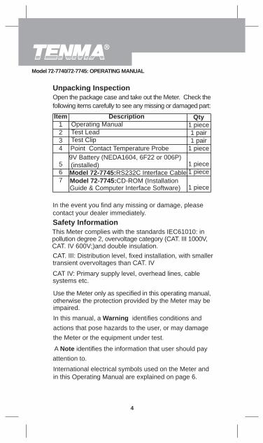
DescriptionOperating ManualTest LeadTest Clip
CAT IV: Primary supply level, overhead lines, cablesystems etc.
4
Unpacking InspectionOpen the package case and take out the Meter. Check thefollowing items carefully to see any missing or damaged part:
In the event you find any missing or damage, pleasecontact your dealer immediately.Safety InformationThis Meter complies with the standards IEC61010: inpollution degree 2, overvoltage category (CAT. III 1000V,CAT. IV 600V;)and double insulation.CAT. III: Distribution level, fixed installation, with smallertransient overvoltages than CAT. IV
Use the Meter only as specified in this operating manual,otherwise the protection provided by the Meter may beimpaired.
In this manual, a Warning identifies conditions andactions that pose hazards to the user, or may damagethe Meter or the equipment under test.
A Note identifies the information that user should payattention to.
International electrical symbols used on the Meter andin this Operating Manual are explained on page 6.
Model 72-7745:CD-ROM (Installation Guide & Computer Interface Software)
Point Contact Temperature Probe
Model 72-7745:RS232C Interface Cable
9V Battery (NEDA1604, 6F22 or 006P) (installed)
Model 72-7740/72-7745: OPERATING MANUAL
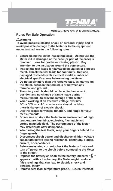
Rules For Safe Operation
To avoid possible electric shock or personal injury, and toavoid possible damage to the Meter or to the equipmentunder test, adhere to the following rules:
l Before using the Meter inspect the case. Do not use theMeter if it is damaged or the case (or part of the case) isremoved. Look for cracks or missing plastic. Payattention to the insulation around the connectors.
l Inspect the test leads for damaged insulation or exposedmetal. Check the test leads for continuity. Replacedamaged test leads with identical model number orelectrical specifications before using the Meter.
l Do not apply more than the rated voltage, as marked onthe Meter, between the terminals or between anyterminal and ground.
l The rotary switch should be placed in the correctposition and no change of range made duringmeasurement , to prevent damage of the Meter.
l When working at an effective voltage over 60VDC or 30V rms AC, special care should be takenthere is danger of electric shock.
l Use the proper terminals, function, and range for yourmeasurements.
l Do not use or store the Meter in an environment of hightemperature, humidity, explosive, flammable andstrong magnetic field. The performance of the Metermay deteriorate after dampened.
l When using the test leads, keep your fingers behind thefinger guards.
l Disconnect circuit power and discharge all high-voltagecapacitors before testing resistance, continuity, diodes,current, or capacitance.
l Before measuring current, check the Meter’s fuses andturn off power to the circuit before connecting the Meterto the circuit.
l Replace the battery as soon as the battery indicator " "appears. With a low battery, the Meter might producefalse readings that can lead to electric shock andpersonal injury.
l Remove test lead, temperature probe, RS232C interface
Warning
5
Model 72-7740/72-7745: OPERATING MANUAL
cable and test clip from the Meter and turn the Meterpower off before opening the case.
l When servicing the Meter, use only the same modelnumber or identical electrical specifications replacementparts.
l The internal circuit of the Meter shall not be altered atwill to avoid damage of the Meter and any accident.
l Soft cloth and mild detergent should be used to clean thesurface of the Meter when servicing. No abrasive andsolvent should be used to prevent the surface of the Meterfrom corrosion, damage and accident.
ll
l
l
The Meter is suitable for indoor use.Under the environment with high (+/-4kV) electrostaticdischarge, the Meter may not be operated as normalcondition. The user may require resetting the Meter.Remove the battery when not used for a prolongedperiod to avoid damage to the Meter.Please constantly check the battery as it may leakwhen it has been using for some time, replace thebattery as soon as leaking appears. A leaking batterywill damage the Meter.
6
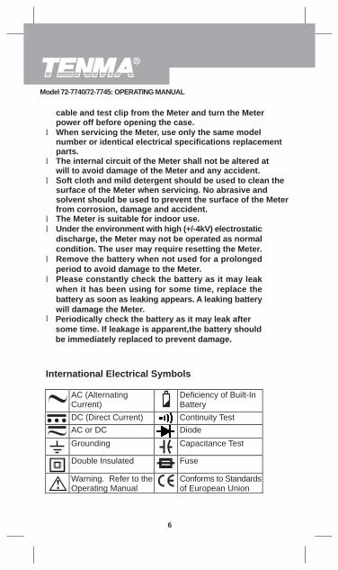
International Electrical Symbols
AC (AlternatingCurrent)
Deficiency of Built-InBattery
DC (Direct Current) Continuity TestAC or DC Diode
Grounding Capacitance Test
Double Insulated Fuse
Warning. Refer to theOperating Manual
Conforms to Standardsof European Union
Model 72-7740/72-7745: OPERATING MANUAL
l Periodically check the battery as it may leak aftersome time. If leakage is apparent,the battery shouldbe immediately replaced to prevent damage.
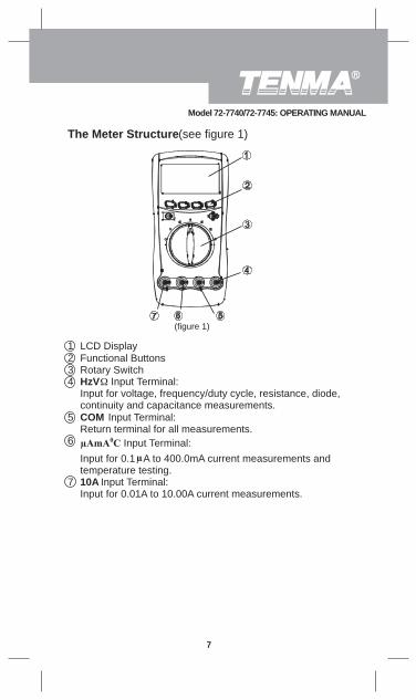
The Meter Structure (see figure 1)
(figure 1)
1 LCD Display2 Functional Buttons3 Rotary Switch4 HzV Input Terminal:
Input for voltage, frequency/duty cycle, resistance, diode,continuity and capacitance measurements.
5 COM Input Terminal:Return terminal for all measurements.
Input Terminal:Input for 0.1 A to 400.0mA current measurements andtemperature testing.
7 10A Input Terminal:Input for 0.01A to 10.00A current measurements.
7
Model 72-7740/72-7745: OPERATING MANUAL
8
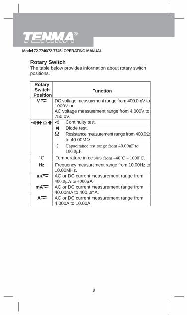
Rotary SwitchThe table below provides information about rotary switchpositions.
RotarySwitchPosition
Function
V DC voltage measurement range from 400.0mV to1000V orAC voltage measurement range from 4.000V to750.0V.
Continuity test.Diode test.Resistance measurement range from 400.0
Temperature in celsiusHz Frequency measurement range from 10.00Hz to
10.00MHz.AC or DC current measurement range from
A.mA AC or DC current measurement range from
40.00mA to 400.0mA.A AC or DC current measurement range from
4.000A to 10.00A.
to 40.00M .
Model 72-7740/72-7745: OPERATING MANUAL
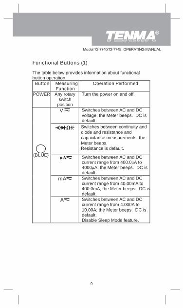
Functional Buttons (1)
9
The table below provides information about functionalbutton operation.Button Measuring
FunctionOperation Performed
POWER Any rotaryswitch
position
Turn the power on and off.
V Switches between AC and DCvoltage; the Meter beeps. DC isdefault.Switches between continuity anddiode and resistance andcapacitance measurements; theMeter beeps.Resistance is default.
Switches between AC and DCcurrent range from 400.0 A to4000 A; the Meter beeps. DC isdefault.
mA Switches between AC and DCcurrent range from 40.00mA to400.0mA; the Meter beeps. DC isdefault.
A Switches between AC and DCcurrent range from 4.000A to10.00A; the Meter beeps. DC isdefault.Disable Sleep Mode feature.
(BLUE)
Model 72-7740/72-7745: OPERATING MANUAL
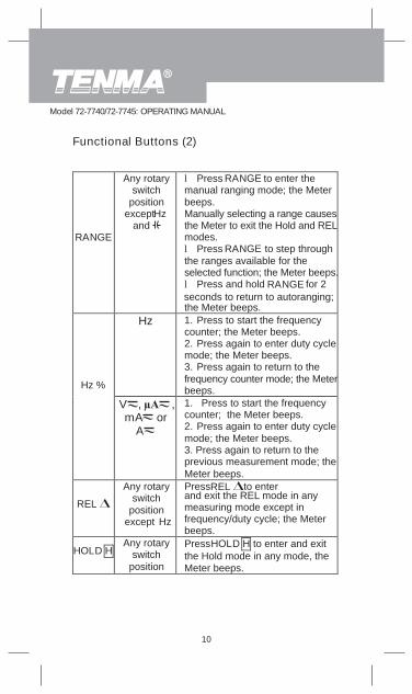
RANGE
Any rotaryswitch
positionexceptHz
and
l Press RANGE to enter themanual ranging mode; the Meterbeeps.Manually selecting a range causesthe Meter to exit the Hold and RELmodes.l Press RANGE to step throughthe ranges available for theselected function; the Meter beeps.l Press and hold RANGE for 2seconds to return to autoranging;the Meter beeps.
Hz 1. Press to start the frequencycounter; the Meter beeps.2. Press again to enter duty cyclemode; the Meter beeps.3. Press again to return to thefrequency counter mode; the Meterbeeps.Hz %
V , ,mA or
A
1. Press to start the frequencycounter; the Meter beeps.2. Press again to enter duty cyclemode; the Meter beeps.3. Press again to return to theprevious measurement mode; theMeter beeps.
REL
Any rotaryswitch
positionexcept Hz
Press to enterand exit the REL mode in anymeasuring mode except infrequency/duty cycle; the Meterbeeps.
Any rotaryswitch
position
Press HOLD H to enter and exitthe Hold mode in any mode, theMeter beeps.
REL
Functional Buttons (2)
HOLD H
10
Model 72-7740/72-7745: OPERATING MANUAL
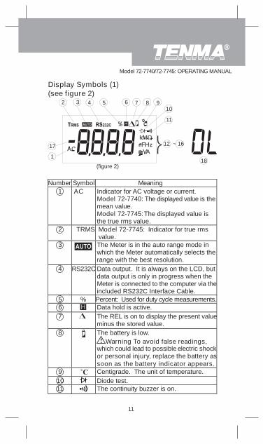
Display Symbols (1)(see figure 2)
Number Symbol Meaning1 AC Indicator for AC voltage or current.
Model 72-7740: The displayed value is themean value.Model 72-7745:The displayed value isthe true rms value.
2 TRMS Model 72-7745: Indicator for true rmsvalue.
3 The Meter is in the auto range mode inwhich the Meter automatically selects therange with the best resolution.
4 RS232C Data output. It is always on the LCD, butdata output is only in progress when theMeter is connected to the computer via theincluded RS232C Interface Cable.
5 % Percent: Used for duty cycle measurements.6 Data hold is active.7 The REL is on to display the present value
minus the stored value.8 The battery is low.
Warning To avoid false readings,which could lead to possible electric shockor personal injury, replace the battery assoon as the battery indicator appears.
9 Centigrade. The unit of temperature.10 Diode test.11 The continuity buzzer is on.
181
2 3 4 5 6 7 8 910
11
12 ~ 1617
(figure 2)
11
Model 72-7740/72-7745: OPERATING MANUAL
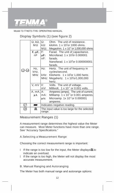
, k ,M
:k :M :
Ohm. The unit of resistance.kilohm. 1 x 10 or 1000 ohms.Megaohm. 1 x 10 or 1,000,000 ohms.
nFF:
nF:
Farad. The unit of capacitance.Microfarad. 1 x 10 or 0.000001farads.Nanofarad. 1 x 10 or 0.000000001farads.
Hz,kHz,MHz
Hz:
kHz:MHz:
Hertz. The unit of frequency incycles/second.Kilohertz. 1 x 10 or 1,000 hertz.Megahertz. 1 x 10 or1,000,000hertz.
V, mV V:mV
Volts. The unit of voltage.Millivolt. 1 x 10 or 0.001 volts.
12~16
A, mA, A:mA:
Amperes (amps). The unit of current.Milliamp. 1 x 10 or 0.001 amperes.Microamp. 1x 10 or 0.000001amperes.
17 Indicates negative reading.18 The input value is too large for the selected
range.
Measurement Ranges (1)
The Meter has both manual range and autorange options:
12
Display Symbols (1) (see figure 2)
A measurement range determines the highest value the Metercan measure. Most Meter functions have more than one range.See “Accuracy Specifications.”
A.Selecting a Measurement Range
Choosing the correct measurement range is important:
l If the range is too low for the input, the Meter displays toindicate an overload.
l If the range is too high, the Meter will not display the mostaccurate measurement.
B. Manual Ranging and Autoranging
Model 72-7740/72-7745: OPERATING MANUAL
l In the autorange mode, the Meter selects the best range forinput signals.This allows you to switch test points without having to resetthe range.
l In the manual range mode, you may select the range.This allows you to override autorange and lock the Meter in aspecific range.
The Meter defaults to the autorange mode in measurementfunctions that have more than one range. When the Meter is inthe autorange mode,
To enter and exit the manual range mode:
1. Press RANGE.The Meter enters the manual range mode and turns off.Pressing RANGE increments the range. When the highestrange is reached, the Meter wraps to the lowest range.
Measurement Ranges (2)
Notel If you manually change the measurement range after entering
the REL or Hold recording modes, the Meter exits thesemodes.
l Under frequency/duty cycle and capacitance measurement,only autorange mode is available.
2. To exit the manual range mode, press and hold RANGE fortwo seconds.The Meter returns to the autorange mode and is displayed.
is displayed.
13
Model 72-7740/72-7745: OPERATING MANUAL
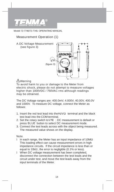
Measurement Operation (1)
A.DC Voltage Measurement (see figure 3)
(figure 3)
To avoid harm to you or damage to the Meter fromelectric shock, please do not attempt to measure voltageshigher than 1000VDC / 750VAC rms although readingsmay be obtained.
The DC Voltage ranges are: 400.0mV, 4.000V, 40.00V, 400.0Vand 1000V. To measure DC voltage, connect the Meter asfollows:
1. Insert the red test lead into the terminal and the blacktest lead into the COM terminal.
2. Set the rotary switch to ; DC measurement is default orpress BLUE button to select DC measurement mode.
3. Connect the test leads across with the object being measured.The measured value shows on the display.
Notel In each range, the Meter has an input impedance of 10M.
This loading effect can cause measurement errors in highimpedance circuits. If the circuit impedance is less than orequal to 10k , the error is negligible (0.1% or less).
l When DC voltage measurement has been completed,disconnect the connection between the test leads and thecircuit under test, and move the test leads away from theinput terminals of the Meter.
Warning
HzV
V
14
Model 72-7740/72-7745: OPERATING MANUAL
Measurement Operation (2)
15
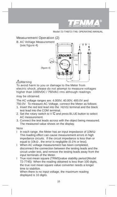
B. AC Voltage Measurement(see figure 4)
(figure 4)
the true root mean square value converter needs a longertime to stabilize.
To avoid harm to you or damage to the Meter fromelectric shock, please do not attempt to measure voltageshigher than 1000VDC / 750VAC rms although readingsmay be obtained.
Warning
The AC voltage ranges are: 4.000V, 40.00V, 400.0V and750.0V. To measure AC Voltage, connect the Meter as follows:1. Insert the red test lead into the terminal and the black
test lead into the COM terminal.2. Set the rotary switch to and press BLUE button to select
AC measurement.3. Connect the test leads across with the object being measured.
The measured value shows on the display.
Notel In each range, the Meter has an input impedance of 10M.
This loading effect can cause measurement errors in highimpedance circuits. If the circuit impedance is less than orequal to 10k , the error is negligible (0.1% or less).
l When AC voltage measurement has been completed,disconnect the connection between the testing leads and thecircuit under test, and remove the testing leads away from theinput terminals of the Meter.
l True root mean square (TRMS)value stability period (Model72-7745): When the reading obtained is less than 100 digits,
When there is no input voltage, the maximum readingdisplayed is 10 digits.
HzV
V
Model 72-7740/72-7745: OPERATING MANUAL
To avoid damage to the Meter or to the devices under test,disconnect circuit power and discharge all the high-voltage
Warning
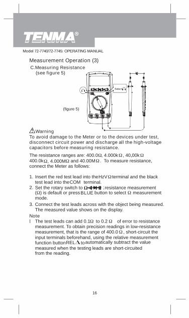
C.Measuring Resistance (see figure 5)
Measurement Operation (3)
(figure 5)
from the reading.
The resistance ranges are: 400.0 , 4.000k , 40.00k,400.0k , 4.000M and 40.00M . To measure resistance,connect the Meter as follows:
1. Insert the red test lead into theHzV terminal and the blacktest lead into theCOM terminal.
2. Set the rotary switch to ; resistance measurement( ) is default or pressBLUE button to select measurementmode.
3. Connect the test leads across with the object being measured.The measured value shows on the display.
16
capacitors before measuring resistance.
Notel The test leads can add 0.1 to 0.2 of error to resistance
measurement. To obtain precision readings in low-resistancemeasurement, that is the range of 400.0 , short-circuit theinput terminals beforehand, using the relative measurementfunction buttonREL tomeasured when the testing leads are short-circuited
automatically subtract the value
Model 72-7740/72-7745: OPERATING MANUAL
l If reading with shorted test leads is not 0.5 , check forloose test leads, incorrect function selection, or enabled DataHold function.
l For high-resistance measurement ( ), it is normal totake several seconds to obtain a stable reading.
l The LCD displays indicating open-circuit for the testedresistor or the resistor value is higher than the maximumrange of the Meter.
l When resistance measurement has been completed,disconnect the connection between the test leads and thecircuit under test, and remove the test leadsfrom theinput terminals of the Meter.
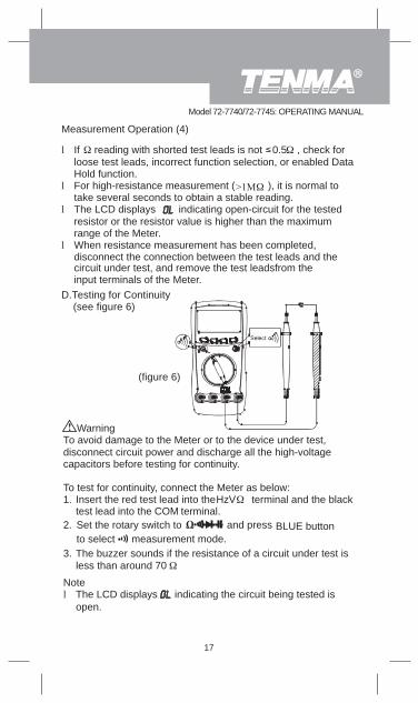
D.Testing for Continuity (see figure 6)
Measurement Operation (4)
(figure 6)
To avoid damage to the Meter or to the device under test,disconnect circuit power and discharge all the high-voltagecapacitors before testing for continuity.
To test for continuity, connect the Meter as below:1. Insert the red test lead into theHzV terminal and the black
test lead into the COM terminal.2. Set the rotary switch to
measurement mode.3. The buzzer sounds if the resistance of a circuit under test is
less than around 70
Warning
and press BLUE button to select
Notel The LCD displays indicating the circuit being tested is
open.
17
Model 72-7740/72-7745: OPERATING MANUAL
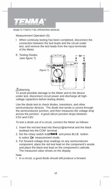
E. Testing Diodes (see figure 7)
To avoid possible damage to the Meter and to the deviceunder test, disconnect circuit power and discharge all high-voltage capacitors before testing diodes.
Use the diode test to check diodes, transistors, and othersemiconductor devices. The diode test sends a current throughthe semiconductor junction, and then measures the voltage dropacross the junction. A good silicon junction drops between0.5V and 0.8V.
Warning
l When continuity testing has been completed, disconnect theconnection between the test leads and the circuit undertest, and remove the test leads from the input terminalsof the Meter.
3. For forward voltage drop readings on any semiconductorcomponent, place the red test lead on the component’s anodeand place the black test lead on the component’s cathode.The measured value shows on the display.
Notel In a circuit, a good diode should still produce a forward
To test a diode out of a circuit, connect the Meter as follows:
Insert the red test lead into theHzV terminal and the blacktestlead into the COM terminal.
2. Set the rotary switch to measurement mode.
and press BLUE buttonto select
Measurement Operation (5)
(figure 7)
1.
18
Model 72-7740/72-7745: OPERATING MANUAL
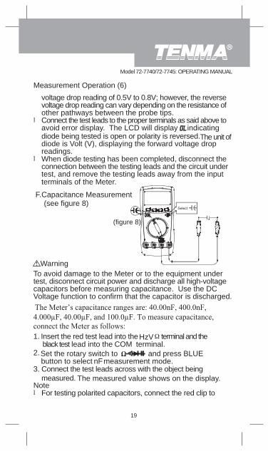
Measurement Operation (6)
F.Capacitance Measurement (see figure 8)
voltage drop reading of 0.5V to 0.8V; however, the reversevoltage drop reading can vary depending on the resistance ofother pathways between the probe tips.
l Connect the test leads to the proper terminals as said above toavoid error display. The LCD will display indicatingdiode being tested is open or polarity is reversed.The unit ofdiode is Volt (V), displaying the forward voltage dropreadings.
l When diode testing has been completed, disconnect theconnection between the testing leads and the circuit undertest, and remove the testing leads away from the inputterminals of the Meter.
(figure 8)
Warning
Insert the red test lead into theHzV terminal and the black test lead into the COM terminal.
2.Set the rotary switch tomeasurement mode.
and press BLUE button to select nF
3. Connect the test leads across with the object beingmeasured. The measured value shows on the display.
Notel For testing polarited capacitors, connect the red clip to
To avoid damage to the Meter or to the equipment undertest, disconnect circuit power and discharge all high-voltagecapacitors before measuring capacitance. Use the DCVoltage function to confirm that the capacitor is discharged.
1.
19
Model 72-7740/72-7745: OPERATING MANUAL
input terminals of the Meter.
input terminals of the Meter.
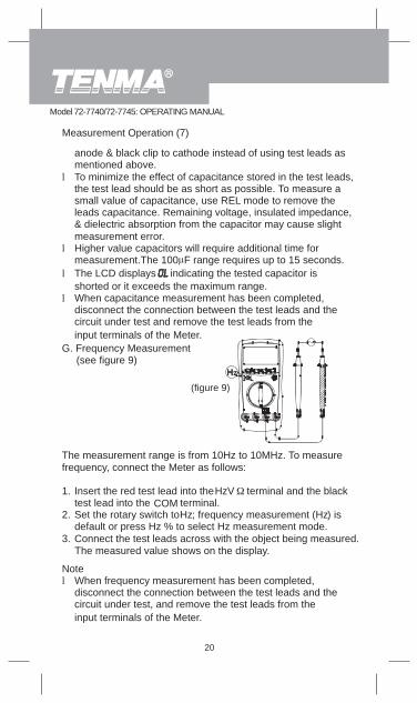
Measurement Operation (7)
20
anode & black clip to cathode instead of using test leads asmentioned above.
l To minimize the effect of capacitance stored in the test leads,the test lead should be as short as possible. To measure asmall value of capacitance, use REL mode to remove theleads capacitance. Remaining voltage, insulated impedance,& dielectric absorption from the capacitor may cause slightmeasurement error.
l Higher value capacitors will require additional time formeasurement.The 100 F range requires up to 15 seconds.
l The LCD displays indicating the tested capacitor isshorted or it exceeds the maximum range.
l When capacitance measurement has been completed,disconnect the connection between the test leads and thecircuit under test and remove the test leads from the
The measured value shows on the display.
The measurement range is from 10Hz to 10MHz. To measurefrequency, connect the Meter as follows:
1. Insert the red test lead into theHzV terminal and the blacktest lead into the COM terminal.
2. Set the rotary switch to Hz; frequency measurement (Hz) isdefault or press Hz % to select Hz measurement mode.
3. Connect the test leads across with the object being measured.
G. Frequency Measurement (see figure 9)
Notel When frequency measurement has been completed,
disconnect the connection between the test leads and thecircuit under test, and remove the test leads from the
(figure 9)
Model 72-7740/72-7745: OPERATING MANUAL
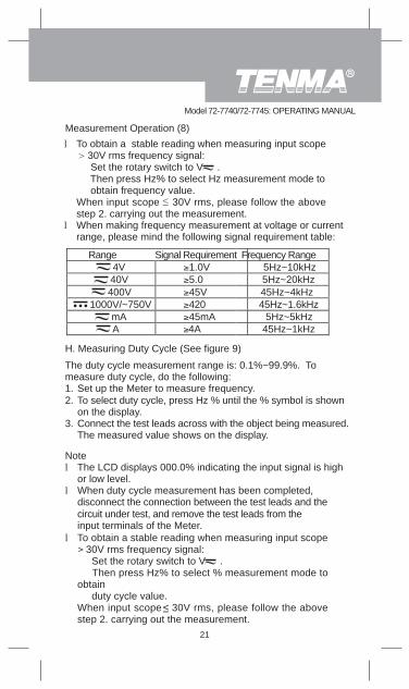
40V400V
1000V/~750VmA
Range Signal Requirement Frequency Range4V 1.0V 5Hz~10kHz
5.0 5Hz~20kHz45V 45Hz~4kHz420 45Hz~1.6kHz45mA 5Hz~5kHz
Measurement Operation (8)
A
l To obtain a stable reading when measuring input scope 30V rms frequency signal: Set the rotary switch to V . Then press Hz% to select Hz measurement mode to obtain frequency value.When input scope 30V rms, please follow the abovestep 2. carrying out the measurement.
l When making frequency measurement at voltage or currentrange, please mind the following signal requirement table:
4A 45Hz~1kHz
l To obtain a stable reading when measuring input scope 30V rms frequency signal: Set the rotary switch to V . Then press Hz% to select % measurement mode toobtain duty cycle value.When input scope 30V rms, please follow the abovestep 2. carrying out the measurement.
H. Measuring Duty Cycle (See figure 9)
The duty cycle measurement range is: 0.1%~99.9%. Tomeasure duty cycle, do the following:1. Set up the Meter to measure frequency.2. To select duty cycle, press Hz % until the % symbol is shown
on the display.3. Connect the test leads across with the object being measured.
The measured value shows on the display.
Notel The LCD displays 000.0% indicating the input signal is high
or low level.l When duty cycle measurement has been completed,
disconnect the connection between the test leads and thecircuit under test, and remove the test leads from theinput terminals of the Meter.
21
Model 72-7740/72-7745: OPERATING MANUAL
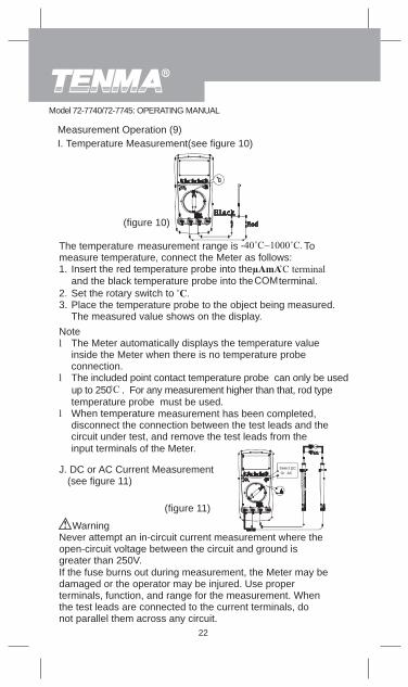
Measurement Operation (9)I. Temperature Measurement(see figure 10)
The temperature measurement range ismeasure temperature, connect the Meter as follows:1. Insert the red temperature probe into the
and the black temperature probe into theCOM terminal.2. Set the rotary switch to3. Place the temperature probe to the object being measured.
The measured value shows on the display.
Never attempt an in-circuit current measurement where theopen-circuit voltage between the circuit and ground isgreater than 250V.If the fuse burns out during measurement, the Meter may bedamaged or the operator may be injured. Use properterminals, function, and range for the measurement. Whenthe test leads are connected to the current terminals, donot parallel them across any circuit.
Warning
J. DC or AC Current Measurement (see figure 11)
Notel The Meter automatically displays the temperature value
inside the Meter when there is no temperature probeconnection.
l The included point contact temperature probe can only be usedup to 250 . For any measurement higher than that, rod typetemperature probe must be used.
l When temperature measurement has been completed,disconnect the connection between the test leads and thecircuit under test, and remove the test leads from theinput terminals of the Meter.
(figure 11)
To
22
Model 72-7740/72-7745: OPERATING MANUAL
(figure 10)
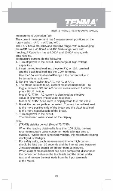
Measurement Operation (10)
auto ranging.
The current measurement has 3 measurement positions on therotary switch: A , mA and A .The A has a 400.0 A and 4000 A range, with auto ranging;the mA has a 40.00mA and 400.0mA range, with autoranging; A position has a 4.000A and 10.00A range, with
To measure current, do the following:1. Turn off power to the circuit. Discharge all high-voltage
capacitors.2. Insert the red test lead into the or 10A terminal
and the black test lead into the COM terminal.Use the10A terminal and A range if the current value tobe tested is an unknown.
3. Set the rotary switch to µA , mA , or A .4. The Meter defaults to DC current measurement mode. To
toggle between DC and AC current measurement function,press BLUE button.Model 72-7740: AC current is displayed as effectivevalue of sine wave (mean value response).Model 72-7745 : AC current is displayed as true rms value.
5. Break the current path to be tested. Connect the red test leadto the more positive side of the break and the black test leadto the more negative side of the break.
6. Turn on power to the circuit.The measured value shows on the display.
l For safety sake, each measurement time for high currentshould be less than 10 seconds and the interval time between2 measurements should be greater than 15 minutes.
l When current measurement has been completed, disconnectthe connection between the test leads and the circuit undertest, and remove the test leads from the input terminalsof the Meter.
Notel (TRMS) stability period: (Model 72-7745)
When the reading obtained is less than 100 digits, the trueroot mean square value converter needs a longer time tostabilize. When there is no input voltage, the maximum readingdisplayed is 10 digits.
23
Model 72-7740/72-7745: OPERATING MANUAL
oC
Operation of Hold Mode
To avoid possibility of electric shock, do not use Hold modeto determine if circuits are without power. The Hold modewill not capture unstable or noisy readings.
The Hold mode is applicable to all measurement functions.l PressHOLD H to enter Hold mode; the Meter beeps.l Press HOLD H again orRANGE or Hz % or turn the rotary
switch to exit Hold mode; the Meter beeps.l In Hold mode, isdisplayed.
Warning
Pressing HOLD H in REL mode makes the Meter stopupdating. PressingHOLDH again to resume updating.
To enter or exit REL mode:l Use rotary switch to select the measurement function before
selectingREL . If measurement function changes manuallyafter REL is selected, the Meter exits the REL mode.
l PressREL to enter REL mode, auto ranging turns off exceptunder capacitance testing mode, and the present measurementrange is locked and display “0” as the stored value.
l PressREL again or turn the rotary switch to reset thestored value and exit REL mode.
The Use of Relative Value Mode
The REL mode applies to all measurement functions exceptfrequency/duty cycle measurement. It subtracts a stored valuefrom the present measurement value and displays the result.
For instance, if the stored value is 20.0V and the presentmeasurement value is 22.0V, the reading would be 2.0V. If anew measurement value is equal to the stored value then display0.0V.
24
Model 72-7740/72-7745: OPERATING MANUAL
The POWER buttonThis is a self-lock switch used to turn on or off the power of theMeter.
The BLUE button
It is used for selecting the required measurement function whenmore than one function exists at one position of the rotaryswitch.
Turning on the Display Backlight
In order to avoid the hazard arising from mistaken readingsin insufficient light or poor vision, please use DisplayBacklight function.
l Press and hold HOLD H for over 2 seconds to turn theDisplay Backlight on.
l Pressand hold HOLD H again for over 2 seconds to turn theDisplay Backlight off, otherwise it will stay on continuously.
Sleep Mode (Model 72-7740)
To preserve battery life, the Meter automatically turns off after30 minutes of inactivity.
To disable the Sleep Mode function, press BLUE button whileturning on the Meter.
Warning
25
Model 72-7740/72-7745: OPERATING MANUAL
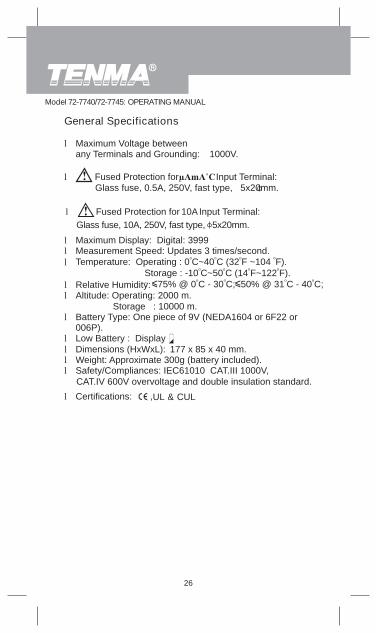
Temperature: Operating : 0oC~40oC (32oF ~104 oF). Storage : -10oC~50oC (14oF~122oF). : 75% @ 0oC - 30oC; 50% @ 31oC - 40oC;
UL & CUL
General Specifications
l Maximum Voltage betweenany Terminals and Grounding: 1000V.
l Fused Protection for Input Terminal:
l Fused Protection for 10AInput Terminal:Glass fuse, 10A, 250V, fast type, 5x20mm.
Glass fuse, 0.5A, 250V, fast type, 5x20mm.
l Maximum Display: Digital: 3999l Measurement Speed: Updates 3 times/second.l
l Relative Humidity:l Altitude: Operating: 2000 m.
Storage : 10000 m.l Battery Type: One piece of 9V (NEDA1604 or 6F22 or
006P).l Low Battery : Displayl Dimensions (HxWxL): 177 x 85 x 40 mm.l Weight: Approximate 300g (battery included).l Safety/Compliances: IEC61010 CAT.III 1000V,
CAT.IV 600V overvoltage and double insulation standard.
l Certifications: ,
26
Model 72-7740/72-7745: OPERATING MANUAL
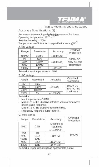
Accuracy: (a% reading + b digits), guarantee for 1 year.Operating temperature: 23oC 5oC.Relative humidity: 75%.Temperature coefficient: 0.1 x (specified accuracy)/1oCA. DC Voltage
Range Resolution Accuracy OverloadProtection
400mV 0.1mV (0.8%+3)4V40V400V
(0.8%+1)
1000V 1V (1%+3)
1000V DC750V AC rmscontinuous.
1mV10mV100mV
l Frequency response 40Hz~400Hz.
400 0.1
14k40k 10400k 1004M 1k
Accuracy Specifications (1)
Remarks: Input impedance
C. Resistance
Range Resolution Accuracy OverloadProtection
(1%+2)
(1.2%+2)(1.5%+2)
1000Vp
Remarks: Open circuit voltage approximate 0.45V.40M 10k
Measure atREL mode(1.2%+2)
B. AC Voltage
Range Resolution Accuracy OverloadProtection
4V40V400V
(1%+5)
750V 1V (1.2%+5)
1000V DC750V AC rmscontinuous.
Remarks:l Input impedance 10M .l Model 72-7740: displays effective value of sine wave
(mean value response).Model 72-7745: displays true rms value.
100mV10mV1mV
27
Model 72-7740/72-7745: OPERATING MANUAL
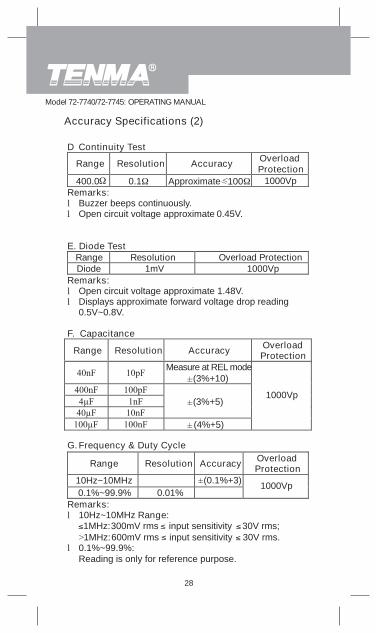
D Continuity Test
Range Resolution Accuracy OverloadProtection
400.0 0.1 Approximate 100 1000VpRemarks:l Buzzer beeps continuously.l Open circuit voltage approximate 0.45V.
E. Diode TestRange Resolution Overload ProtectionDiode 1mV 1000Vp
Remarks:l Open circuit voltage approximate 1.48V.l Displays approximate forward voltage drop reading
0.5V~0.8V.
F. Capacitance
Resolution Accuracy OverloadProtection
Measure at REL mode(3%+10)
(3%+5)
(4%+5)
1000Vp
G. Frequency & Duty Cycle
Range Resolution Accuracy OverloadProtection
10Hz~10MHz0.1%~99.9% 0.01%
1000Vp
Remarks:l 10Hz~10MHz Range:
l 0.1%~99.9%:Reading is only for reference purpose.
Accuracy Specifications (2)
300mV rms input sensitivity 30V rms;600mV rms input sensitivity 30V rms.
1MHz:1MHz:
Range
(0.1%+3)
28
Model 72-7740/72-7745: OPERATING MANUAL
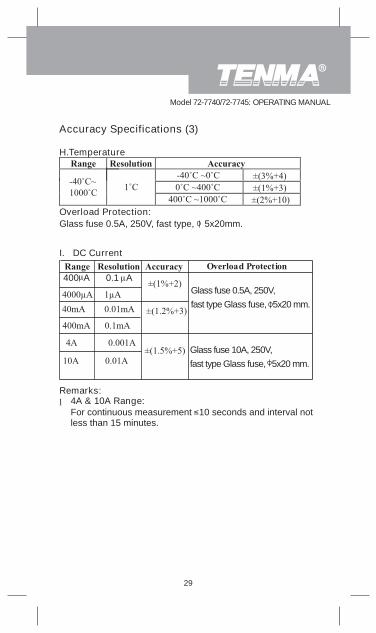
H.Temperature
For continuous measurement 10 seconds and interval notless than 15 minutes.
I. DC Current
Glass fuse 0.5A, 250V,fast type Glass fuse, 5x20 mm.
Glass fuse 10A, 250V,fast type Glass fuse, 5x20 mm.
Overload Protection:Glass fuse 0.5A, 250V, fast type, 5x20mm.
Remarks:
Accuracy Specifications (3)
400 A 0.1 A
l 4A & 10A Range:
29
Model 72-7740/72-7745: OPERATING MANUAL
0.5A, 250V,fast type Glass fuse, 5x20 mm.
10A, 250V,fast type Glass fuse, 5x20 mm.
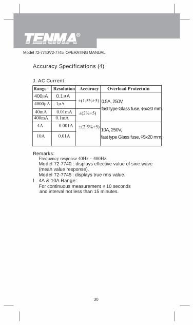
Accuracy Specifications (4)
J. AC Current
400 A 0.1 A
30
and interval not less than 15 minutes.
Remarks:
Model 72-7740 : displays effective value of sine wave(mean value response).Model 72-7745 : displays true rms value.
l 4A & 10A Range:For continuous measurement 10 seconds
Model 72-7740/72-7745: OPERATING MANUAL
31
to the10A terminal.
MAINTENANCEThis section provides basic maintenance information including
battery and fuse replacement instruction.
performance test, and service information.
water inside the case.
field.
To test the fuse:
Do not attempt to repair or service your Meter unless youare qualified to do so and have the relevant calibration,
Warning
To avoid electrical shock or damage to the Meter, do not get
A. General Service
l
l Periodically wipe the case with a damp cloth and milddetergent. Do not use abrasives or solvents.
l To clean the terminals with cotton bar with detergent, as dirtor moisture in the terminals can affect readings.
l Turn off the power of the Meter when it is not in use and takeout the battery when not using for a long time.Take out the battery when it is using for a long time.
l Do not use or store the Meter in a place of humidity, hightemperature, explosive, inflammable and strong magnetic
B. Testing the Fuses
fuses with identical amperage, voltage, and speed ratings.
To avoid electrical shock or personal injury, remove the testleads and any input signals before replacing the battery orfuse.To prevent damage or injury, install ONLY replacement
Warning
1. Set the rotary switch to
2. Plug a test lead into the terminalHzV and touch the probe
and pressBLUE button to select
Model 72-7740/72-7745: OPERATING MANUAL
If the Meter does not work while the fuse is all right, send it toyour dealer for repair.
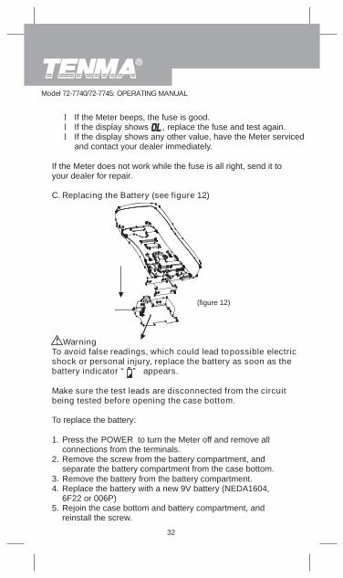
C. Replacing the Battery (see figure 12)
To avoid false readings, which could lead to electricshock or personal injury, replace the battery as soon as thebattery indicator “ ” appears.
Make sure the test leads are disconnected from the circuitbeing tested before opening the case bottom.
To replace the battery:
1.
2.
3.4.
5.
Press the POWER to turn the Meter off and remove allconnections from the terminals.Remove the screw from the battery compartment, andseparate the battery compartment from the case bottom.Remove the battery from the battery compartment.Replace the battery with a new 9V battery (NEDA1604,6F22 or 006P)Rejoin the case bottom and battery compartment, andreinstall the screw.
Warning
l If the Meter beeps, the fuse is good.l If the display shows , replace the fuse and test again.l If the display shows any other value, have the Meter serviced
and contact your dealer immediately.
(figure 12)
possible
32
Model 72-7740/72-7745: OPERATING MANUAL
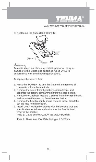
Fuse 1: Glass fuse 0.5A, 250V, fast type, 5x20mm.
Fuse 2: Glass fuse 10A, 250V, fast type, 5x20mm.
To avoid electrical shock, arc blast, personal injury ordamage to the Meter, use specified fuses ONLY inaccordance with the following procedure.
To replace the Meter’s fuse:
Press the POWER to turn the Meter off and remove allconnections from the terminals.Remove the screw from the battery compartment, andseparate the battery compartment from the case bottom.Remove the 2 rubber feet and 2 screws from the case bottom,and separate the case top from the case bottom.Remove the fuse by gently prying one end loose, then takeout the fuse from its bracket.Install ONLY replacement fuses with the identical type andspecification as follows and make sure the fuse is fixedfirmly in the bracket.
Warning
(figure 13)
1.
2.
3.
4.
5.
D. Replacing the Fuses(see figure 13)
33
Model 72-7740/72-7745: OPERATING MANUAL
always results from improper operation.Replacement of the fuses is seldom required. Burning of a fuse
6.
7. Rejoin the case bottom and case top, and reinstall the 2screws and 2 rubber feet.
Rejoin the battery compartment and the case top, andreinstall the screw.
34
Model 72-7740/72-7745: OPERATING MANUAL