Embed Size (px)
Citation preview

Model 6202-1 Reduced Oxygen Breathing Device 2
Operator’s Guide Revision 8 September 2nd 2016 Software Rev. 6202-2.00-XX
Environics Inc. 69 Industrial Park Road East
Tolland, CT 06084-2805 USA Phone (860) 872-1111 Fax (860) 870-9333
E-mail: [email protected] Web: HTTP://WWW.ENVIRONICS.COM
II
COPYRIGHT © 2016 Environics Inc. All Rights Reserved. This manual and the software contained within the product(s) described are copyrighted with all rights reserved.
TRADEMARKS Environics is a registered trademark of Environics Inc. All other brand names, company names and product names mentioned are the property of their respective owners.
PATENTS This product is licensed from the U.S. Navy under U.S. Patent Application No. 10/959.764
WARRANTY Environics Inc. warrants this product to be free from defects in material and workmanship for a period of one year from the date of shipment. Environics warrants the following expendable items for 30 days from the date of shipment: fuses, lamps, batteries. During the warranty period, Environics will, at our option, either repair or replace any product that proves to be defective.
To exercise this warranty, contact Environics at the address below for assistance and instructions for returning the products. Repaired or replaced products are warranted for the balance of the original warranty period or at least 30 days.
LIMITATION OF WARRANTY This warranty does not apply to defects resulting from product modification made without Environics’ express written consent, or misuse of any product or part. This warranty also does not apply to software, damage from battery leakage or problems arising from normal wear or failure to follow instructions.
This warranty is in lieu of all other warranties, expressed or implied, including any implied warranty of merchantability or fitness for a particular use. The remedies provided herein are the buyer’s sole and exclusive remedies.
Neither Environics nor any of its employees shall be liable for any direct, indirect, special, incidental or consequential damages arising out of the use of its instruments and software even if Environics has been advised in advance of the possibility of such damages. Such excluded damages shall include, but are not limited to: costs of removal and installation, losses sustained as the result of injury to any person or damage to property.
WARNING READ THIS MANUAL CAREFULLY BEFORE USING THIS INSTRUMENT.
FAILURE TO DO SO MAY VOID THE WARRANTY, DAMAGE THE INSTRUMENT OR CAUSE SERIOUS INJURY.

III
ROBD2 Operator’s Guide changes
Manual Revision
#
Software Revision
#
Manual Release
Date Enhancements
1 0.93-XX 11/1/2004 Initial release
2 0.96-XX 10/26/2005 Added MFC safety feature, changed fitting color codes, reduced
maximum altitude to 34K feet, modified self-tests, added purge to pilot test menu, added purge after test altitudes (self calibration)
3 0.96-XX 02/09/2006 Fixed erroneous information and typographical errors
Added statement (bottom page 1) Added Breathing loop pressure port (Bottom page 6), Added safety feature (Top page 31)
4 0.96-XX 04/26/2006 Modified O2 dump screen (page 29).
5 0.96-XX 9/27/2006 Added restrictions to connecting pulse oximeter probe (pages 3, 10 & 12) Added note about powering on the pulse oximeter in Quick start (page 10)
6 0.97-xx 5/5/2010 Added O2 DUMP PRESSURE setting to OPTION menu Modified O2 Dump and O2 Pressure safety feature section Corrected Patent information
7 2.00-XX 7/30/2016 Updated manual to include modifications made for new model 6202-1 8 2.00-XX 9/2/2016 Added information about the vent plug in the vent port

IV
TABLE OF CONTENTS
LIST OF FIGURES v LIST OF ABBREVIATIONS / ACRONYMS vi OVERVIEW 1 SYSTEM LAYOUT 2
Front Panel Layout 2 Rear Panel Layout 4
UNPACKING AND INSTALLATION 7 Standard packaging and unpacking 7 Transport case option and unpacking 7 Installation 7
POWER AND GAS CONNECTIONS 8 Power Connection 8 Gas Connection 9
QUICK START PROCEDURE 10 POWER UP AND SELF-TESTS 11
Power up 11 Warmup 11 Self-test/calibration 11 Self-test Operations 12 Self Calibration Operations 13
SYSTEM OPERATION 15 Entering data 15 Main Screen - Ready mode 16 START – Pilot Test mode 17 Option menu 21
SAFETY FEATURES 26 PULSE OXIMETER 28
SpO2 and Pulse Rate Displays 28 SpO2 and Pulse Rate Alarms 29

V
LIST OF FIGURES
FIGURE 1 - FRONT PANEL LAYOUT .................................................................. 2 FIGURE 2 - REAR PANEL LAYOUT .................................................................... 4 FIGURE 3 - P&ID ................................................................................................ 34

VI
LIST OF ABBREVIATIONS / ACRONYMS
AC Alternating Current
EMI Electromagnetic Interference
HZ Hertz
LCD Liquid Crystal Display
LPM Liters Per Minute
MFC Mass Flow Controller
NAG Nitrogen and Air Generator
P&ID Piping and Instrument Diagram
PSIG Pounds Per Square Inch Gauge
RFI Radio Frequency Interference
SUT Subject Under Test
VAC Volts, Alternating Current
VDC Volts, Direct Current
OVERVIEW
ROBD2 USER’S GUIDE SEPTEMBER 2016 1
OVERVIEW
The second generation Reduced Oxygen Breathing Device (ROBD2) is a computerized gas-blending instrument. The system uses Thermal Mass Flow Controllers (MFC) to mix breathing air and nitrogen to produce the sea level equivalent atmospheric oxygen contents for altitudes up to 40,000 feet. The MFCs are calibrated on primary flow standards traceable to the National Institute of Standards and Technology (NIST). NIST is a federal agency whose mission is to develop and promote measurement, standards, and technology to enhance productivity, facilitate trade, and improve the quality of life. Several safety features are built into the ROBD2 to prevent over-pressurization of the Pilot’s mask and to prevent reduced oxygen contents below those being requested for a particular altitude. The software is Menu driven. The main operator’s menu consists of three selections, simplifying the use of the system for the field operator. Built in self-tests verify all system component functionality before the operation of the system can begin. If any self-tests fail, the system will not operate.
This manual contains information and guidance for setting up and operating the ROBD2.
Step by step instructions are provided for connecting power and gas sources, running self-tests, running the self-calibration routines and running a pre-programmed sequence of altitudes on the subject under test (SUT).
Descriptions of alarms and safety features are provided along with actions to be taken in the event of an alarm condition.
A piping and instrument diagram (P&ID) is provided on the last page of the manual for an overview of the electrical, pneumatic and electro-pneumatic components contained within the instrument.
IMPORTANT: The ROBD2 operator should be certified in first-aid and CPR and have access to communication in the event of an emergency.
Prior to participation in ROBD2 training or research, the subject under test should have the equivalent to a FAA physical of any class or military flight physical and be screened for current health status prior to the run.

SYSTEM LAYOUT
ROBD2 USER’S GUIDE SEPTEMBER 2016 2
SYSTEM LAYOUT
Front Panel Layout
Figure 1 - Front panel layout
SYSTEM LAYOUT
ROBD2 USER’S GUIDE SEPTEMBER 2016 3
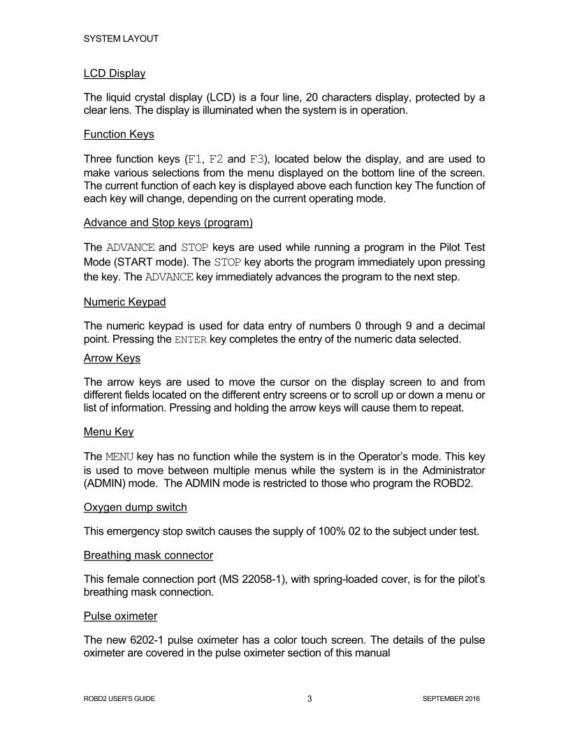
LCD Display
The liquid crystal display (LCD) is a four line, 20 characters display, protected by a clear lens. The display is illuminated when the system is in operation.
Function Keys
Three function keys (F1, F2 and F3), located below the display, and are used to make various selections from the menu displayed on the bottom line of the screen. The current function of each key is displayed above each function key The function of each key will change, depending on the current operating mode.
Advance and Stop keys (program)
The ADVANCE and STOP keys are used while running a program in the Pilot Test Mode (START mode). The STOP key aborts the program immediately upon pressing the key. The ADVANCE key immediately advances the program to the next step.
Numeric Keypad
The numeric keypad is used for data entry of numbers 0 through 9 and a decimal point. Pressing the ENTER key completes the entry of the numeric data selected.
Arrow Keys
The arrow keys are used to move the cursor on the display screen to and from different fields located on the different entry screens or to scroll up or down a menu or list of information. Pressing and holding the arrow keys will cause them to repeat.
Menu Key
The MENU key has no function while the system is in the Operator’s mode. This key is used to move between multiple menus while the system is in the Administrator (ADMIN) mode. The ADMIN mode is restricted to those who program the ROBD2.
Oxygen dump switch
This emergency stop switch causes the supply of 100% 02 to the subject under test.
Breathing mask connector
This female connection port (MS 22058-1), with spring-loaded cover, is for the pilot’s breathing mask connection.
Pulse oximeter
The new 6202-1 pulse oximeter has a color touch screen. The details of the pulse oximeter are covered in the pulse oximeter section of this manual

SYSTEM LAYOUT
ROBD2 USER’S GUIDE SEPTEMBER 2016 4
Rear Panel Layout
Figure 2 - Rear panel layout

SYSTEM LAYOUT
ROBD2 USER’S GUIDE SEPTEMBER 2016 5
Power Input The power entry module supplies AC power to the internal power supplies. The internal power supplies convert and regulate the AC signal to the five DC voltages required by the system electronics. The power entry module has integrated EMI/RFI filtration and switch one or both hot lines dependent upon 110 or 220 VAC operation. The power entry module also has two replaceable fuses.
Gas Inputs These gas inputs supply source gas to the system components. The optional quick connect fittings for these ports are colored and keyed. The Nitrogen input is black, the Air input is yellow and the oxygen input is green. The Nitrogen and air inputs should be pressurized to a dynamic pressure of 40 PSIG and the oxygen input should be adjusted to a dynamic pressure of 20 PSIG.
RS-232 Port One 9-pin RS-232 serial port is connected to the embedded controller of the ROBD system. This port is used for remote control of the ROBD2 using a host computer and communications software. Communication protocol is provided in the programming and technical guide. This protocol can be used to develop control and data collection programs using programs such as National Instruments’ LabVIEW.
Cooling fan The cooling fan moves approximately 36 cu/ft per minute of filtered air through the ROBD chassis and out the cooling vents on the top cover of the chassis. The cooling fan should not be obstructed.
Service port The service port is used for factory calibration of the thermal mass flow controllers. Important: The silver plug must not be removed during normal operation. Pulse oximeter probe connector Plug the pulse oximeter probe into this port. Once connected the probe is latched. The probe is removed, by pressing the side tabs on the probe connector and pulling it out.
SYSTEM LAYOUT
ROBD2 USER’S GUIDE SEPTEMBER 2016 6
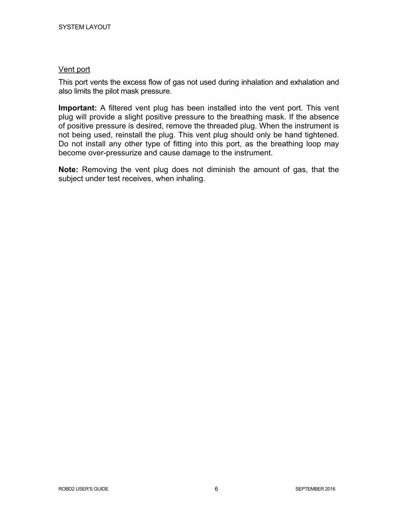
Vent port This port vents the excess flow of gas not used during inhalation and exhalation and also limits the pilot mask pressure.
Important: A filtered vent plug has been installed into the vent port. This vent plug will provide a slight positive pressure to the breathing mask. If the absence of positive pressure is desired, remove the threaded plug. When the instrument is not being used, reinstall the plug. This vent plug should only be hand tightened. Do not install any other type of fitting into this port, as the breathing loop may become over-pressurize and cause damage to the instrument.
Note: Removing the vent plug does not diminish the amount of gas, that the subject under test receives, when inhaling.

UNPACKING AND INSTALLATION
ROBD2 USER’S GUIDE SEPTEMBER 2016 7
UNPACKING AND INSTALLATION
Standard packaging and unpacking
1. Remove the system from the cardboard box in which it was delivered from the factory.
2. Remove and read any important instructions or notes found within the box.
3. Save and store the box and foam inserts in the event the system needs to be returned to the factory or delivered to another site for operation.
4. If the optional pressure regulators were purchased with the system, they are delivered in a separate box.
Transport case option and unpacking
1. The transport case is provided with the ability to be locked. If a lock has been added, remove the lock and undo the rotary latches.
2. Remove the cover and pull the system out by the side handles.
3. If the optional pressure regulators were purchased with the system, they are stored under the area taken up by the ROBD2.
Installation
1. Install the system on a table or cart 2. Remove caps on the N2, air and 02 in ports. Do not remove the plug in the
Service port or the vented plug in the Vent port. See the rear panel layout section, on page 6 for instructions for the vent plug in the vent port.
3. Proceed to the section titled Power and gas connections.

POWER AND GAS CONNECTIONS
ROBD2 USER’S GUIDE SEPTEMBER 2016 8
POWER AND GAS CONNECTIONS
After the RODB2 is unpacked, the system should be connected to power and the appropriate gas sources to the gas inlet ports on the rear panel. Environics recommends the use of a power conditioner, as recommended for computers, to eliminate power problems from affecting system operation.
Power Connection
1. The indicating insert of the power entry module should read either 115V or
230V dependent upon the actual voltage being used. If it is not set for the voltage being connected, remove the insert, rotate it to the correct setting and reinstall; see below. Set for 115V for 100-120 VAC 50/60 HZ and 230 V for 200-240 VAC 50/60 HZ operation.
2. Insert the standard power cord supplied with the system into the power connector on the rear panel and insert the plug into a properly grounded outlet. The standard unit allows for 110 – 240 VAC (50/60 Hz).
3. Do not turn the power on at this point, proceed to the section titled Gas connection.
Voltage indicator
115V 115V
POWER AND GAS CONNECTIONS
ROBD2 USER’S GUIDE SEPTEMBER 2016 9
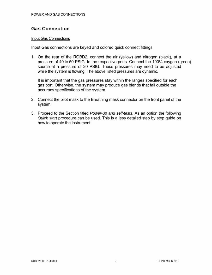
Gas Connection
Input Gas Connections
Input Gas connections are keyed and colored quick connect fittings. 1. On the rear of the ROBD2, connect the air (yellow) and nitrogen (black), at a
pressure of 40 to 50 PSIG, to the respective ports. Connect the 100% oxygen (green) source at a pressure of 20 PSIG. These pressures may need to be adjusted while the system is flowing. The above listed pressures are dynamic.
It is important that the gas pressures stay within the ranges specified for each gas port. Otherwise, the system may produce gas blends that fall outside the accuracy specifications of the system.
2. Connect the pilot mask to the Breathing mask connector on the front panel of the
system.
3. Proceed to the Section titled Power-up and self-tests. As an option the following Quick start procedure can be used. This is a less detailed step by step guide on how to operate the instrument.

QUICK START PROCEDURE
ROBD2 USER’S GUIDE SEPTEMBER 2016 10
QUICK START PROCEDURE
1. Before Powering on the system make sure to perform the steps outlined in the section titled Power and gas connection.
2. Connect the pulse oximeter probe any time before or after powering on the instrument.
3. Power on the system.
4. Allow the warm-up time to elapse (10 minutes)
5. Once warm up time has elapsed, press the SELFTST function key. Follow the self-test prompts carefully as errors in following the prompts will cause failures in the self-test. After the self-tests have run, the system will perform a self-calibration. The 02 sensor will calibrate and test altitudes will be performed.
DANGER: During self-tests, gas will be delivered to the mask and vent port. Do not breathe through the mask during the self-test or self-calibration process, since oxygen will not be present at all times.
6. The pilot’s mask can now be connected.
7. Press the START key to enter the PILOT TEST MENU.
8. Enter RUNPRG to run a pre-programmed sequence. Select one of twenty pre-saved programs.
9. Either allow program to complete or select MENU to run a manual altitude. Manual altitude will interrupt the program. Select EXIT to return to the program.
10. Select ADVANCE or STOP keys to perform the respective function. ADVANCE will automatically skip to the next step in the program, STOP will abort the program.
11. If the subject is at risk of becoming hypoxic, press the 02 DUMP emergency switch. Once the switch is turned off (turn clockwise) the flow of 100% 02 will stop.

POWER UP AND SELF-TESTS
ROBD2 USER’S GUIDE SEPTEMBER 2016 11
POWER UP AND SELF-TESTS
Power up
The system power switch is on the rear panel power entry module. It is important that all gas connections are made before self-tests. Refer to the section titled Gas connection.
Warmup
The system requires a 10 minute warmup period after it is powered up. During the warmup period, the screen will display WARMUP and show a 600 second (10 minute) countdown. During the warmup period, the system cannot be run and no self-tests can be performed. The only available function is the OPTION key. After the warmup period, the system will show TEST ERR, indicating that the system self-tests have not been run. The SELFTST function key is now available, allowing the system self-test to be run.
Self-test/calibration
Pressing the SELFTST key will automatically run all self-test and calibration steps sequentially. Some tests require user interface while others do not.
At any time after the system has been powered up and self-tests have run for the first time, these self-tests can be run again, either individually or all together, from the OPTION menu. This is useful for troubleshooting purposes to detect a failure that has occurred after the initial power up self-test routine.
Select SELF-TEST from the options menu to run the system self-tests. Select SELF-CALIBRATE to run the system calibration functions, including O2 sensor calibration.
DANGER: During self-tests, gas will be delivered to the mask, breathing bag and vent port. Do not breathe through the mask during the self-test or self-calibration process, since oxygen will not be present at all times.

POWER UP AND SELF-TESTS
ROBD2 USER’S GUIDE SEPTEMBER 2016 12
Self-test Operations
Oxygen sensor test
The oxygen sensor test will check the on-board oxygen sensor accuracy. The system will provide air to the sensor for 20 seconds and report the 02 content as read by the un-calibrated 02 sensor. If the 02 content falls outside the limits set by the test, the test will fail. Click OK to acknowledge the failure.
Oxygen dump test (tests the O2 switch, O2 valve and alarm)
This test checks the operation of the emergency oxygen dump switch and the valve that provides the flow of 100% oxygen. The operator will be prompted in this test to activate and de-activate the dump switch. Pay close attention to the prompts. After the switch is tested, the system will verify the operation of the DUMP valve by verifying that the O2 sensor reads 100% O2. Finally, the test will sound the audible oxygen alarm. The operator will be prompted to press OK if the alarm is audible and FAIL if it is not.
Oxygen pressure switch test
This test will verify that the oxygen pressure switch works properly. The operator will be prompted to remove pressure from the oxygen port. This can be done by disconnecting the hose at the O2 cylinder. The quick connect fitting on the gas regulator has a check valve. When the hose is removed, the gas regulator is isolated. Be sure to follow the prompts carefully.
Pulse Oximeter test
This test verifies that the embedded micro controller, of the ROBD2, can communicate with the integrated pulse oximeter and that the pulse oximeter has passed its own internal self-test. The pulse oximeter has its own built in self-test which runs upon power up.
Air MFC shutdown test
This test confirms the operation of a safety feature to shut the system down in the event of low input air pressure. The air MFC has an alarm signal that activates if the internal MFC valve opens to maximum capacity. This generally indicates that there is not enough pressure on the MFC to satisfy the required flow rate. This would lead to elevated N2 levels in the breathing loop during normal operation. This feature uses the MFC alarm signal to stop flow and provide 100% oxygen to the breathing loop. The operator must follow the prompts to disconnect and reconnect the air source to confirm the passage of test.

POWER UP AND SELF-TESTS
ROBD2 USER’S GUIDE SEPTEMBER 2016 13
Self-Calibration Operations
Before running programs, the system must run through its self-calibration routine at the start of each operating day, and every time the system is powered on. These tests will run automatically after the system has warmed up for 10 minutes. If this process is not run, the system will not allow the operator to enter the START mode. At any time after the system has run the automatic self-test function, individual self-tests or self-calibration routines can be run individually from the OPTION menu. To run the self-calibration sequence, select the self-calibration menu item from the OPTION menu. Depending upon the gas source being used, the self-calibration process will vary. Either way, no operator interface is required during each self-calibration routine. Oxygen sensor calibration
The oxygen sensor calibration is run automatically from the SELFTST key, or can be run separately by selecting CAL O2 SENSOR from the OPTION – SELF CALIBRATE menu.
To calibrate the oxygen sensor, first air is delivered to the oxygen sensor. The 02 content of air is known to be 20.947. The following will be displayed:
02 SENSOR CAL 10MEASURING 02 AIR 02= 20.9% V=.830 CANCEL
ANALYZING AIR 02 REMAINING TIME
ACTUAL 02 PERCENT AS READ BY 02 SENSOR
DC VOLTAGE PRODUCED BY 02 SENSOR

POWER UP AND SELF-TESTS
ROBD2 USER’S GUIDE SEPTEMBER 2016 14
ALTITUDE BEING TESTED
TESTING ALTITUDES ALT:20000 02: 9.09 MEASURING 02….
EXPECTED 02VALUE
ALTITUDE BEING TESTED
TESTING ALTITUDES ALT:20000 02: 9.09 PASSED 02=9.10
EXPECTED 02VALUE
MEASURED 02 VALUE
RESULT
Once the system has calibrated the sensor for air, it will proceed to supplying 100% 02 to the sensor. The following will be displayed:
Once the sensor has calibrated to 100% 02, the calibration will display complete and automatically move on to the next calibration routine. If any failures occur during this test, refer to the troubleshooting section in the Programming and Technical Guide.
Pressing CANCEL during the process will terminate the calibration process and the new calibration data will not be stored.
Test altitudes
This routine checks the accuracy of the blending system and the oxygen sensor by running air and nitrogen blends that span the full range of the MFCs. Three altitudes are tested; 5000 feet, 20000 feet and 34000 feet. From the OPTION menu, select TEST ALTITUDES. The following information will be displayed during the testing of each altitude:
The following information will be displayed after each altitude is tested:
ACTUAL 02 PERCENT AS READ BY 02 SENSOR
02 SENSOR CAL 10MEASURING 02 100% 02= 99.5% V= 3.803
CANCEL
ANALYZING 100% 02
REMAINING TIME
DC VOLTAGE PRODUCED BY 02 SENSOR

SYSTEM OPERATION
ROBD2 USER’S GUIDE SEPTEMBER 2016 15
SYSTEM OPERATION
Entering data
At various times during system operation the operator is required to enter data into the system. Entry of numeric data is performed by using the numeric keypad. Press the number key(s) representing the desired data values and press ENTER to record the data in the appropriate field. If the numbers entered completely fill the field, the value is automatically accepted and the ENTER key is not required. Pressing an arrow key will also complete the entry and move the cursor to another field. The system automatically adds a decimal point followed by zeros to fill the rest of the field, if required. For fields requiring alphanumeric data to be entered, the arrow keys may also be used to input data. The following listing shows the order of the alphanumeric and punctuation symbols that can be accessed by pressing the up and down arrow keys:
ABCDEFGHIJKLMNOPQRSTUVWXYZ0123456789.+-/()%#
Note that the digits 0 – 9 and . can also be entered directly by pressing the corresponding key on the numeric keypad. To enter alphanumeric data, press the up/down arrow until the desired character is displayed. Then press the ENTER key, or use the left/right arrow keys to position the cursor in the desired location. The SPACE function key is used to enter a blank space. The CLEAR function key will clear all data entered. The ENTER function key will complete the entry of data.

SYSTEM OPERATION
ROBD2 USER’S GUIDE SEPTEMBER 2016 16
Main Screen - Ready mode
The ROBD2 was designed with emphasis on simplicity and ease of operation. The system’s menu-driven software guides the operator through all operating routines. The following menu items are available to the user. START
The START key is used to enter the Pilot Test mode. The Pilot Test mode is where all pilot testing takes place. The START key is disabled until the warmup time has elapsed, and all self-test and calibration operations have completed successfully.
SELFTST
The SELFTST key runs the system self-test and calibration operations. These operations must be run before the START key can be used to enter the Pilot Test mode. The menu selection disappears after the Self-test process has run. Self-test and self-calibration routines can be run individually or together from the OPTION menu.
OPTION
The OPTION key is used to enter the OPTION menu, which is used to set various system options, display self-test results and run self-test and self- calibration. Also, the OPTION menu is used to set time and date, adjust display contrast and view software revision and system serial number.
(DAY) (DATE) (TIME) ENVIRONICS ROBD2 READY START SELFTST OPTION

SYSTEM OPERATION
ROBD2 USER’S GUIDE SEPTEMBER 2016 17
START – Pilot Test mode
Standby status in Pilot Test mode
Once in this menu, the operator can select to run a program.
RUNPRG – Running a flight profile
The RUNPRG mode is used to conveniently recall one of 20 saved programs with up to 99 steps of altitude changes. The program must be setup prior to using the RUN mode (refer to the PROGRAM mode section of the technical manual). When entering the RUNPRG mode, the following screen will appear (Note: program names shown are for example purposes only).
Using the up and down arrow keys, select the program to run. The highlighted program will have the greater than sign to the left of the program number. NOTE: this mode requires instrument pre-programming. This programming information is in the Programming and technical manual. The following information will be seen in two separate screens. By pressing the MENU key and VIEW, the screens can be toggled.
# NAME TYPE > 1 BASIC HYPOXIA HRT 2 SIMULATOR FSHT SELECT EXIT
PILOT TEST MENU RUNPRG EXIT

SYSTEM OPERATION
ROBD2 USER’S GUIDE SEPTEMBER 2016 18
CHG 34000 @ 30000 F/M 25000 7.11% 38
PROGRAM STEP CURRENT ALTITUDE
ACTUAL 02 PERCENT
SET ALTITUDE BAR 34000 FEET MAX AS SHOWN CURRENT ALTITUDE BAR
TREND BARS
REMAINING TIME
CHG 34000 @ 30000 F/M ALT = 25000 Elp = 30 S 02 = 7.11% Rmn = 38 S BLP = 1.30
PROGRAM STEP INFOCURRENT ALTITUDE
ACTUAL 02 PERCENT AS READ BY 02 SENSOR
ELAPSED TIME
BREATHING LOOPPRESSURE “H2O
REMAINING TIME
RUNPRG SCREEN 1
RUNPRG SCREEN 2

SYSTEM OPERATION
ROBD2 USER’S GUIDE SEPTEMBER 2016 19
RUNPRG EXAMPLE STEP 1: HOLD AT 34000 FEET FOR 2 MINUTES STEP 2: CHANGE TO 0 FEET AT 18000 FT/MIN STEP 3: HOLD AT 0 FEET FOR 1 MINUTE STEP 4: CHANGE TO 20000 FEET AT 30000 FT/MIN STEP 5: END OF PROGRAM
STEP 1:
STEP 2:
STEP 3:
STEP 4:
HLD 34000 FOR 2 MIN ALT = 34000 Elp = 50S 02 = 4.4% Rmn = 70S
BLP = 1.35
HLD 34000 FOR 2 MIN 34000 4.40% 70
SCREEN 1 SCREEN 2
CHG 0 @ 18000 F/M ALT = 34000 Elp = 20 S 02 = 4.37% Rmn = 113 S
BLP = 1.20
CHG 0 @ 18000 F/M 34000 4.37% 113
SCREEN 1 SCREEN 2
HLD 0 FOR 1 MIN ALT = 0 Elp = 10S 02 = 21.2% Rmn = 50S
BLP = 1.25
HLD 0 FOR 40S 0 21.2% 50
SCREEN 1 SCREEN 2
CHG 20000 @ 30000 F/M ALT = 13000 Elp = 26S 02 = 12.42% Rmn = 14S
BLP = 1.42
CHG 20000 @ 30000 F/M 13000 12.42% 14
SCREEN 1 SCREEN 2

SYSTEM OPERATION
ROBD2 USER’S GUIDE SEPTEMBER 2016 20
While in the RUNPRG mode, pressing the STOP key will abort the program.
Pressing the ADVANCE key while in the run mode will advance the program to the next step, regardless of how much time remains in the current step.
Pressing the 02 DUMP switch will cause the program to shut down and the system will supply 100% 02 to the SUT. O2 will continue to flow until the dump switch is disengaged by turning it clockwise.
Pressing the MENU key while in the run mode will toggle the screens back and forth between the two run mode display screens. One screen contains the bar graph representation of desired altitude, actual altitude and a running trend of altitude. The other display screen gives more detailed information, including breathing loop pressure, elapsed step time, remaining step time, actual 02 content as read by the onboard oxygen sensor, desired altitude, current altitude and the actual program step information.
Manual altitude override
While in the RUNPRG mode, you can manually override a program step and go directly to any desired altitude. Entering a manual altitude will pause the current program and ascend or descend to the new altitude entered.
To enable manual altitude control while running a program, press the MENU key and then select MANUAL. Enter the new altitude and press ENTER.
You can enter new altitude values as often as desired. You can also increase or decrease the current altitude in increments of 1000 ft., but pressing the up or down arrow keys.
To resume the program from where it was interrupted, press EXIT

SYSTEM OPERATION
ROBD2 USER’S GUIDE SEPTEMBER 2016 21
Option menu
The OPTION menu is used to run self-test and self-calibration functions, and to change various system settings.
Pressing the OPTION key will bring up the following display.
The OPTION menu contains a menu with the following items:
TEST RESULTS SELF-TEST SELF CALIBRATE ROBD FLOW RATE ADMIN MODE SET TIME/DATE ADJUST CONTRAST SYSTEM INFO
Select the desired function by using the arrow keys, then press ENTER.
> TEST RESULTS SELF TEST SELF CALIBRATE EXIT

SYSTEM OPERATION
ROBD2 USER’S GUIDE SEPTEMBER 2016 22
TEST RESULTS
The Test Results function displays the results of all Self-test and Self Calibrate functions. The test item is listed on the left, with the result shown on the right. Below is a sample test result display:
TEST RESULTS PULSE OXIM - OK O2 DUMP VALVE - OK O2 DUMP SWITCH-FAIL O2 DUMP ALARM - OK O2 PRESS SW - OK O2 SENSOR - OK O2 SENSOR CAL -SKIP ALTITUDE TEST –SKIP AIR MFC SHUTDN-FAIL
"OK" indicates that the test has been run and completed successfully. "FAIL" indicates that the test has been run but has failed. "SKIP" indicates that the test has been skipped and has not yet been run. The software will not allow access to the PILOT TEST menu until all tests show "OK" Press the EXIT key to return to the OPTION menu. SELF-TEST
The Self-test function allows various self-tests to be run, either all at once or individually. The available menu items are shown below.
TEST ALL TEST MFCS TEST O2 SENSOR TEST O2 DUMP TEST O2 PRESS SW TEST PRESS SENSOR TEST PULSE OX. TEST MFC SHUTDOWN
To run all Self-tests, position the cursor on TEST ALL and press ENTER. For each self-test, the software will ask you to confirm that you want to run the test. Select YES to run the test, or NO to skip to the next test.

SYSTEM OPERATION
ROBD2 USER’S GUIDE SEPTEMBER 2016 23
To run an individual self-test, position the cursor on the desired test and press ENTER.
While a test is running, you may be prompted to perform various actions. Be sure to follow the prompts carefully, otherwise the test may fail. In the event that a test fails, you will be prompted with "TEST FAILED. REPEAT TEST?". Press YES to rerun the test, otherwise press NO.
SELF CALIBRATE
The Self Calibrate function allows self-calibration checks to be run, either all at once or individually. The available menu items are shown below.
CAL ALL CAL O2 SENSOR TEST ALTITUDES
To run all Self Calibrations, position the cursor on CAL ALL and press ENTER. For each test, the software will ask you to confirm that you want to run the test. Select YES to run the test, or NO to skip to the next test.
To run an individual test, position the cursor on the desired test and press ENTER.
While a test is running, you may be prompted to perform various actions. Be sure to follow the prompts carefully, otherwise the test may fail. In the event that a test fails, you will be prompted with "TEST FAILED. REPEAT TEST?". Press YES to rerun the test, otherwise press NO.
ROBD FLOW RATE
The flow rate of the 6202-1 is adjustable from 40 LPM to 80 LPM. The nominal setting is 50 LPM to provide enough gas flow to the subject under test while preserving valuable gas. However, if there is not enough flow to satisfy a subject under test, it can be increased.
NOTE: With the new flow range of 40 to 80 LPM for mask flow, adjust the pressure of O2 accordingly to match the flow of O2, during emergency oxygen delivery, to the total mask flow during a flight profile. Do not exceed 35 PSIG on the oxygen pressure setting.

SYSTEM OPERATION
ROBD2 USER’S GUIDE SEPTEMBER 2016 24
ADMIN MODE
The ADMINinstrator MODE allows access to Administrator level functions, which include programming of test routines (PROG mode) and system functions (SYSTEM mode) such as MFC calibration.
To enter ADMIN mode, select ADMIN MODE from the menu and press ENTER. If there is an Administrator password, you will be prompted to enter it. If there is no password, the system will automatically switch to ADMIN mode.
To exit ADMIN mode, select ADMIN MODE from the menu, and press ENTER. The system will disable administrator mode, regardless of any password setting.
When the system is in Admin mode, "ADMIN" will be displayed on the main menu screen.
SET TIME/DATE
The SET TIME/DATE function allows you to set the Time and Date displayed on LCD screen. Three fields to display the day, date and time will appear.
With the left/right arrow keys, move the cursor to the desired date or time field to be changed and press the up and down arrow keys to set the correct time and/or date. Note: the day of the week is calculated by the system automatically.
When the correct time and date are entered, press the EXIT function key to return to the OPTION menu.

SYSTEM OPERATION
ROBD2 USER’S GUIDE SEPTEMBER 2016 25
ADJUST CONTRAST
The contrast of the LCD display is affected somewhat by the angle at which the display is viewed as well as the ambient temperature. To adjust the contrast for optimum results:
1. Using the up and down arrow keys, move the pointer cursor down to the line that reads ADJUST CONTRAST and press the ENTER key. The following screen appears:
2. Press the up arrow to increase the contrast on the screen. When increasing the contrast, the contrast number will increase to a maximum 100. Use the down arrow to decrease the contrast on the screen. When decreasing the contrast, the contrast number will decrease to a minimum value of 0. The numerical value is shown for reference since the user may not detect a change in contrast on the screen. The contrast value will change in increments of five.
3. After reaching the desired contrast setting, press DONE to return to the OPTION menu.
SYSTEM INFO
Selecting System Info will bring up a display of the system model number, serial number and software version.
ADJUST CONTRAST CONTRAST = 100 / TO CHANGE
DONE
SAFETY FEATURES
ROBD2 USER’S GUIDE SEPTEMBER 2016 26
SAFETY FEATURES
There are a number of built-in safety features to either alert the operator or stop the operation of the system and go to a “safe” mode of operation.
Oxygen dump switch
An emergency Oxygen Dump switch has been provided to supply 100% oxygen on demand as the subject under test (SUT) becomes hypoxic. The emergency switch is activated by depressing it, which starts the flow of oxygen. Once the SUT has recovered as determined by pulse oximeter analysis, turning the switch clockwise will stop the flow of 100% 02.
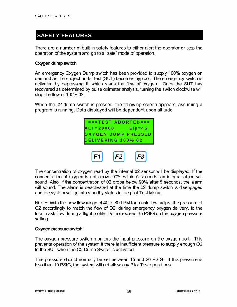
When the 02 dump switch is pressed, the following screen appears, assuming a program is running. Data displayed will be dependent upon altitude
The concentration of oxygen read by the internal 02 sensor will be displayed. If the concentration of oxygen is not above 90% within 5 seconds, an internal alarm will sound. Also, if the concentration of 02 drops below 90% after 5 seconds, the alarm will sound. The alarm is deactivated at the time the 02 dump switch is disengaged and the system will go into standby status in the pilot Test Menu.
NOTE: With the new flow range of 40 to 80 LPM for mask flow, adjust the pressure of O2 accordingly to match the flow of O2, during emergency oxygen delivery, to the total mask flow during a flight profile. Do not exceed 35 PSIG on the oxygen pressure setting.
Oxygen pressure switch
The oxygen pressure switch monitors the input pressure on the oxygen port. This prevents operation of the system if there is insufficient pressure to supply enough O2 to the SUT when the O2 Dump Switch is activated.
This pressure should normally be set between 15 and 20 PSIG. If this pressure is less than 10 PSIG, the system will not allow any Pilot Test operations.
===TEST ABORTED=== ALT=28000 Elp=4S OXYGEN DUMP PRESSED DELIVERING 100% 02

SAFETY FEATURES
ROBD2 USER’S GUIDE SEPTEMBER 2016 27
If Low O2 Pressure is detected in the Ready mode, the system will display LOW O2 instead of READY, on the screen
In the Pilot Test Menu, if any of the Pilot Test keys (RUNPRG or PPT) are pressed during a Low O2 Pressure condition, the system will display the following screen and prevent the system from running in the Pilot Test Menu.
The system will once again function when pressure is restored above 12 PSIG.
Oxygen alarm
The O2 alarm will sound for two different scenarios. The 02 alarm is only active for the O2 dump feature. After pressing the emergency oxygen dump switch, if the 02 has not reached 90% in 5 seconds, the alarm sounds. The alarm will remain active until the emergency switch is turned off. Also, if during an O2 dump, the oxygen content drops below 90%, the alarm will sound.
Oxygen analysis
Using the onboard oxygen sensor, if the oxygen content, in any pilot test mode, drops below 3.8%, the system will automatically turn on the oxygen dump and display a warning message.
Overpressure detect
Using the onboard pressure sensor, if the pressure to the mask rises above 20” H20, the system will turn on the oxygen dump
Low air flow detect
The Air MFC (MFC1) has an alarm signal that activates if the internal MFC valve opens to maximum capacity. This generally indicates that there is not enough pressure on the MFC to satisfy the required flow rate. This would lead to elevated N2 levels in the breathing loop during normal operation. This feature uses the MFC alarm signal to stop flow and provide 100% oxygen to the breathing loop. A message appears indicated the failure.
PILOT TEST MENU *LOW 02 PRESSURE* *CANNOT RUN TEST*
RUNPRG EXIT

PULSE OXIMETER
ROBD2 USER’S GUIDE SEPTEMBER 2016 28
PULSE OXIMETER
SpO2 and Pulse Rate Displays
Like the 6202 pulse ox, the 6202-1 takes about 10 seconds after placing the probe on the finger to register valid data. This is inherent to the pulse oximeter electronics/firmware.
The measured SpO2 and pulse rate are displayed side by side as shown in the diagram below. The oximeter ensures that only valid pulsatile signals are processed. Bad, invalid or the absence of data causes alerts to occur and may also cause the displays to show “- - -” and “- - -” in the SpO2 and pulse rate displays.
The displays are updated every half a second as the monitor is acquiring data. The message box, in the lower left hand corner of the display, will indicate whether or not the probe is connected to the unit or if the probe is connected to the unit, but not connected to the SUT. Otherwise, when actively displaying valid data, this message box will be blank. The area in the lower right corner of the display is used for alarms and information related to the pass or fail state of the internal self-test of the pulse oximeter.
PULSE OXIMETER
ROBD2 USER’S GUIDE SEPTEMBER 2016 29
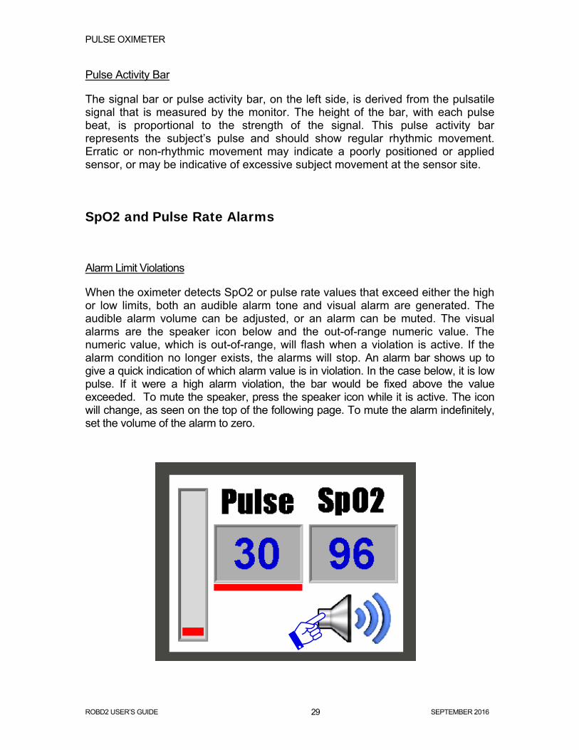
Pulse Activity Bar
The signal bar or pulse activity bar, on the left side, is derived from the pulsatile signal that is measured by the monitor. The height of the bar, with each pulse beat, is proportional to the strength of the signal. This pulse activity bar represents the subject’s pulse and should show regular rhythmic movement. Erratic or non-rhythmic movement may indicate a poorly positioned or applied sensor, or may be indicative of excessive subject movement at the sensor site.
SpO2 and Pulse Rate Alarms
Alarm Limit Violations
When the oximeter detects SpO2 or pulse rate values that exceed either the high or low limits, both an audible alarm tone and visual alarm are generated. The audible alarm volume can be adjusted, or an alarm can be muted. The visual alarms are the speaker icon below and the out-of-range numeric value. The numeric value, which is out-of-range, will flash when a violation is active. If the alarm condition no longer exists, the alarms will stop. An alarm bar shows up to give a quick indication of which alarm value is in violation. In the case below, it is low pulse. If it were a high alarm violation, the bar would be fixed above the value exceeded. To mute the speaker, press the speaker icon while it is active. The icon will change, as seen on the top of the following page. To mute the alarm indefinitely, set the volume of the alarm to zero.

PULSE OXIMETER
ROBD2 USER’S GUIDE SEPTEMBER 2016 30
Setting SpO2 and pulse rate alarm limits
To access the alarm setting screen, press the pulse or SpO2 display windows shown below. For touchscreen variables either a finger or stylus can be used.
PULSE OXIMETER
ROBD2 USER’S GUIDE SEPTEMBER 2016 31
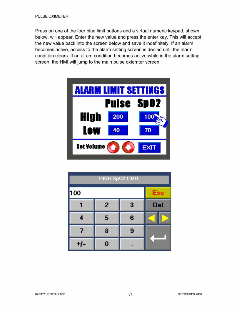
Press on one of the four blue limit buttons and a virtual numeric keypad, shown below, will appear. Enter the new value and press the enter key. This will accept the new value back into the screen below and save it indefinitely. If an alarm becomes active, access to the alarm setting screen is denied until the alarm condition clears. If an alram condition becomes active while in the alarm setting screen, the HMI will jump to the main pulse oxiemter screen.
PULSE OXIMETER
ROBD2 USER’S GUIDE SEPTEMBER 2016 32
Adjusting the alarm and pulse bar volume
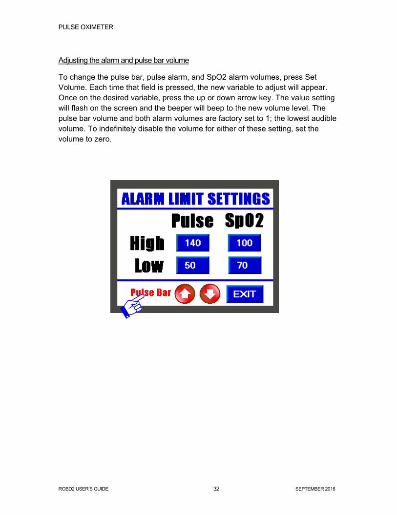
To change the pulse bar, pulse alarm, and SpO2 alarm volumes, press Set Volume. Each time that field is pressed, the new variable to adjust will appear. Once on the desired variable, press the up or down arrow key. The value setting will flash on the screen and the beeper will beep to the new volume level. The pulse bar volume and both alarm volumes are factory set to 1; the lowest audible volume. To indefinitely disable the volume for either of these setting, set the volume to zero.

PULSE OXIMETER
ROBD2 USER’S GUIDE SEPTEMBER 2016 33
Pulse oximeter self-test When the 6202-1 is powered on, the classic tone sequence of the 6202 pulse oximeter will be heard. After the initial sound sequence, there will be a single tone, within about 8 seconds, and the screen will flash pass in the lower right hand corner. This means that the internal pulse oximeter self-test has passed. If for some reason the internal self-test fails to pass, the word fail will appear and remain on the screen until the self-test passes. This will also prevent the 6202-1 self-test from passing as well, rendering the 6202-1 inoperable. If during normal operation, the 6202-1 computer loses it communication link with the pulse oximeter and is unable to recover, the word fail will appear.

PULSE OXIMETER
ROBD2 USER’S GUIDE SEPTEMBER 2016 34
Figure 3 - P&ID