Embed Size (px)
Citation preview
M O D E L 5 9 0G A S C H R O M A T O G R A P H
A d d e n d u m H a r d w a r eR e f e r e n c e M a n u a l
Applies to BothDaniel Danalyzer Model 590
Rosemount Analytical Model 590
Part Number 3-9000-534Revision B
SEPTEMBER 2005

Model 590 Dual Oven Gas ChromatographSystem Reference Manual
NOTICE
DANIEL MEASUREMENT AND CONTROL, INC. AND ROSEMOUNT ANALYTICAL, INC.(COLLECTIVELY, “SELLER”) SHALL NOT BE LIABLE FOR TECHNICAL OR EDITORIAL ERRORS INTHIS MANUAL OR OMISSIONS FROM THIS MANUAL. SELLER MAKES NO WARRANTIES,EXPRESSED OR IMPLIED, INCLUDING THE IMPLIED WARRANTIES OF MERCHANTABILITY ANDFITNESS FOR A PARTICULAR PURPOSE WITH RESPECT TO THIS MANUAL AND, IN NO EVENT,SHALL SELLER BE LIABLE FOR ANY SPECIAL OR CONSEQUENTIAL DAMAGES INCLUDING,BUT NOT LIMITED TO, LOSS OF PRODUCTION, LOSS OF PROFITS, ETC.
PRODUCT NAMES USED HEREIN ARE FOR MANUFACTURER OR SUPPLIER IDENTIFICATIOONLY AND MAY BE TRADEMARKS/REGISTERED TRADEMARKS OF THESE COMPANIES.
THE CONTENTS OF THIS PUBLICATION ARE PRESENTED FOR INFORMATIONAL PURPOSESONLY, AND WHILE EVERY EFFORT HAS BEEN MADE TO ENSURE THEIR ACCURACY, THEYARE NOT TO BE CONSTRUED AS WARRANTIES OR GUARANTEES, EXPRESSED OR IMPLIED,REGARDING THE PRODUCTS OR SERVICES DESCRIBED HEREIN OR THEIR USE ORAPPLICABILITY. WE RESERVE THE RIGHT TO MODIFY OR IMPROVE THE DESIGNS ORSPECIFICATIONS OF SUCH PRODUCTS AT ANY TIME.
SELLER DOES NOT ASSUME RESPONSIBILITY FOR THE SELECTION, USE OR MAINTENANCEOF ANY PRODUCT. RESPONSIBILITY FOR PROPER SELECTION, USE AND MAINTENANCE OFANY SELLER PRODUCT REMAINS SOLELY WITH THE PURCHASER AND END-USER.
DANIEL AND THE DANIEL LOGO ARE REGISTERED TRADEMARKS OF DANIEL INDUSTRIES,INC. THE ROSEMOUNT AND ROSEMOUNT ANALYTICAL LOGO THE ARE REGISTEREDTRADEMARKS OF ROSEMOUNT ANALYTICAL, INC. THE EMERSON LOGO IS A TRADEMARKAND SERVICE MARK OF EMERSON ELECTRIC CO.
COPYRIGHT © 2005 BY DANIEL MEASUREMENT AND CONTROL, INC., HOUSTON, TEXAS, U.S.A.
All rights reserved. No part of this work may be reproduced or copied in any form or by any means - graphic, electronic, or mechanical — without first receiving the written permission of Daniel Measurement and Control, Inc. Houston, Texas, U.S.A.
WARRANTY
1. LIMITED WARRANTY: Subject to the limitations contained in Section 2 herein and except asotherwise expressly provided herein, Daniel Measurement and Control, Inc. and RosemountAnalytical, Inc., (collectively“Seller”) warrants that the firmware will execute the programminginstructions provided by Seller, and that the Goods manufactured or Services provided by Sellerwill be free from defects in materials or workmanship under normal use and care until theexpiration of the applicable warranty period. Goods are warranted for twelve (12) months fromthe date of initial installation or eighteen (18) months from the date of shipment by Seller,whichever period expires first. Consumables and Services are warranted for a period of 90 daysfrom the date of shipment or completion of the Services. Products purchased by Seller from athird party for resale to Buyer ("Resale Products") shall carry only the warranty extended by theoriginal manufacturer. Buyer agrees that Seller has no liability for Resale Products beyond makinga reasonable commercial effort to arrange for procurement and shipping of the Resale Products. IfBuyer discovers any warranty defects and notifies Seller thereof in writing during the applicablewarranty period, Seller shall, at its option, promptly correct any errors that are found by Seller inthe firmware or Services, or repair or replace F.O.B. point of manufacture that portion of theGoods or firmware found by Seller to be defective, or refund the purchase price of the defectiveportion of the Goods/Services. All replacements or repairs necessitated by inadequatemaintenance, normal wear and usage, unsuitable power sources, unsuitable environmentalconditions, accident, misuse, improper installation, modification, repair, storage or handling, orany other cause not the fault of Seller are not covered by this limited warranty, and shall be atBuyer's expense. Seller shall not be obligated to pay any costs or charges incurred by Buyer orany other party except as may be agreed upon in writing in advance by an authorized Seller rep-resentative. All costs of dismantling, reinstallation and freight and the time and expenses ofSeller's personnel for site travel and diagnosis under this warranty clause shall be borne by Buyerunless accepted in writing by Seller. Goods repaired and parts replaced during the warrantyperiod shall be in warranty for the remainder of the original warranty period or ninety (90) days,whichever is longer. This limited warranty is the only warranty made by Seller and can beamended only in a writing signed by an authorized representative of Seller. Except as otherwiseexpressly provided in the Agreement, THERE ARE NO REPRESENTATIONS OR WARRANTIES OFANY KIND, EXPRESSED OR IMPLIED, AS TO MERCHANTABILITY, FITNESS FOR PARTICULARPURPOSE, OR ANY OTHER MATTER WITH RESPECT TO ANY OF THE GOODS OR SERVICES. Itis understood that corrosion or erosion of materials is not covered by our guarantee.
2. LIMITATION OF REMEDY AND LIABILITY: SELLER SHALL NOT BE LIABLE FOR DAMAGESCAUSED BY DELAY IN PERFORMANCE. THE SOLE AND EXCLUSIVE REMEDY FOR BREACH OFWARRANTY HEREUNDER SHALL BE LIMITED TO REPAIR, CORRECTION, REPLACEMENT ORREFUND OF PURCHASE PRICE UNDER THE LIMITED WARRANTY CLAUSE IN SECTION 1HEREIN. IN NO EVENT, REGARDLESS OF THE FORM OF THE CLAIM OR CAUSE OF ACTION(WHETHER BASED IN CONTRACT, INFRINGEMENT, NEGLIGENCE, STRICT LIABILITY, OTHERTORT OR OTHERWISE), SHALL SELLER'S LIABILITY TO BUYER AND/OR ITS CUSTOMERSEXCEED THE PRICE TO BUYER OF THE SPECIFIC GOODS MANUFACTURED OR SERVICESPROVIDED BY SELLER GIVING RISE TO THE CLAIM OR CAUSE OF ACTION. BUYER AGREESTHAT IN NO EVENT SHALL SELLER'S LIABILITY TO BUYER AND/OR ITS CUSTOMERS EXTENDTO INCLUDE INCIDENTAL, CONSEQUENTIAL OR PUNITIVE DAMAGES. THE TERM"CONSEQUENTIAL DAMAGES" SHALL INCLUDE, BUT NOT BE LIMITED TO, LOSS OFANTICIPATED PROFITS, LOSS OF USE, LOSS OF REVENUE AND COST OF CAPITAL.
iModel 590 Dual Oven GC
TABLE OF CONTENTS
INTRODUCTION 1. ABOUT THIS MANUAL ..................................1-1
1.1 Equipment Description ...................................1-2
1.2 Analyzer Assembly ........................................1-3
1.3 C9 + Features ..............................................1-3
1.4 C9 + Applications.........................................1-5
1.5 C6+ with Trace H2S Features ........................1-6
1.6 C6+ with Trace H2S Applications ...................1-7
1.7 Software Compatibility ..................................1-7
INSTALLATION 2. INSTALLING THE DUAL GC UNIT....................2-1
2.1 Dual Analyzer Installation ...............................2-1
2.2 Dual GC Wiring Guide ....................................2-2
2.3 Dual GC Controller Installation ........................2-3
2.4 Controller to Dual Analyzer Wiring ...................2-3
OPERATIONS 3. MODEL 590 DUAL GC SYSTEM OPERATIONS ...............................................3-1
APPENDIX A, LIST OFENGINEERING
DRAWINGS
A.1 ENGINEERING DRAWINGS ............................ A-1
SEP 2005 Introduction

ii Model 590 Dual Oven GC
This page is intentionally left blank.
Appendix A, List of Engineering Drawings SEP 2005
INTRODUCTION 1-1Model 590 Dual Oven GC
1
INTRODUCTION
1.1 ABOUT THIS MANUAL
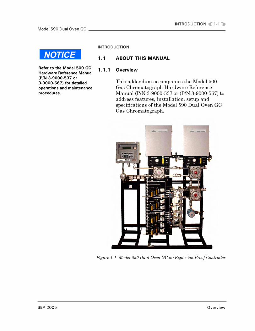
1.1.1 Overview
This addendum accompanies the Model 500 Gas Chromatograph Hardware Reference Manual (P/N 3-9000-537 or (P/N 3-9000-567) to address features, installation, setup and specifications of the Model 590 Dual Oven GC Gas Chromatograph.
Figure 1-1 Model 590 Dual Oven GC w/Explosion Proof Controller
Refer to the Model 500 GC Hardware Reference Manual (P/N 3-9000-537 or 3-9000-567) for detailed operations and maintenance procedures.
SEP 2005 Overview
1-2 INTRODUCTIONModel 590 Dual Oven GC
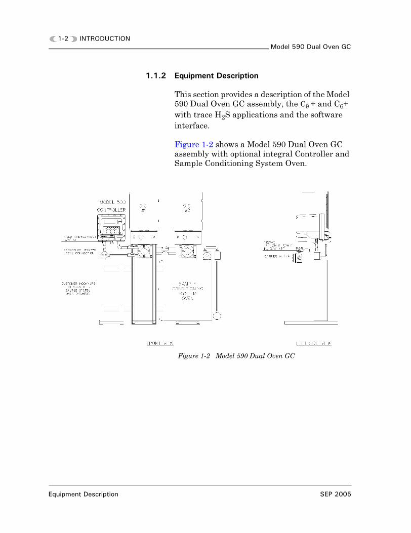
1.1.2 Equipment Description
This section provides a description of the Model 590 Dual Oven GC assembly, the C9 + and C6+ with trace H2S applications and the software interface.
Figure 1-2 shows a Model 590 Dual Oven GC assembly with optional integral Controller and Sample Conditioning System Oven.
Figure 1-2 Model 590 Dual Oven GC
Equipment Description SEP 2005
INTRODUCTION 1-3Model 590 Dual Oven GC
1.1.3 Analyzer Assembly
The Model 590 Dual Oven GC is a dual analyzer, high speed system engineered to meet specific field applications. The two most common applications are:
• C9 + compositional analysis of rich pipeline gas (C1-C9 +, N2 and CO2) with optional hydrocarbon Dew Point calculation application.
• C6+ with trace H2S
• Process applications requiring more than three column valves
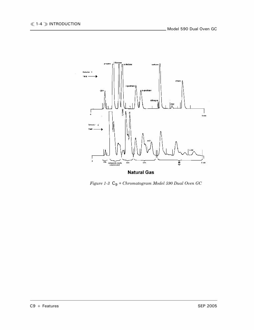
1.1.4 C9 + Features
The Model 590 Dual Oven GC allows for trace measurement on C9 + components:
• Dual ovens for fast analysis time (approximately five minutes)
• Oven 1 measurement of C1-C5’s, N2, and CO2
• Oven 2 measurement of C6’s, C7’s, C8’s and C9 +
• Uses GPA 2145, ISO 6976, and AGA8 physical property data
• Shared Sample Conditioning System
SEP 2005 Analyzer Assembly
1-4 INTRODUCTIONModel 590 Dual Oven GC
Figure 1-3 C9 + Chromatogram Model 590 Dual Oven GC
C9 + Features SEP 2005
INTRODUCTION 1-5Model 590 Dual Oven GC
1.1.5 C9 + Applications
• Compositional analysis of pipeline gas(C1-C9 +, N2, and CO2)
• Calculates heating value (BTU), specific gravity, and compressibility
• Optional hydrocarbon Dew Point calculations in English or metric (refer to P/N 3-9000-950 or P/N 3-9000-951; Dew Point manual)
• Allows “tracking” of hydrocarbon Dew Point changes for optimal pipeline/pressure control
• Hydrocarbon condensates (high in BTU) represent “lost” energy and cause metering errors
• Liquids cause serious damage to pipelines and machinery (gas turbines)
• More frequent occurrence with deregulation (economics of processing)
• 2 ppm minimum detectability on C9 + peak
• Supports a more complete AGA8 calculation
LOSS OF DATA
It is recommended that C9+Applications use a Sample Conditioning Oven and heat trace sample lines to prevent dropout of heavy components.
Failure to observe this precaution may result in loss of data.
SEP 2005 C9 + Applications
1-6 INTRODUCTIONModel 590 Dual Oven GC
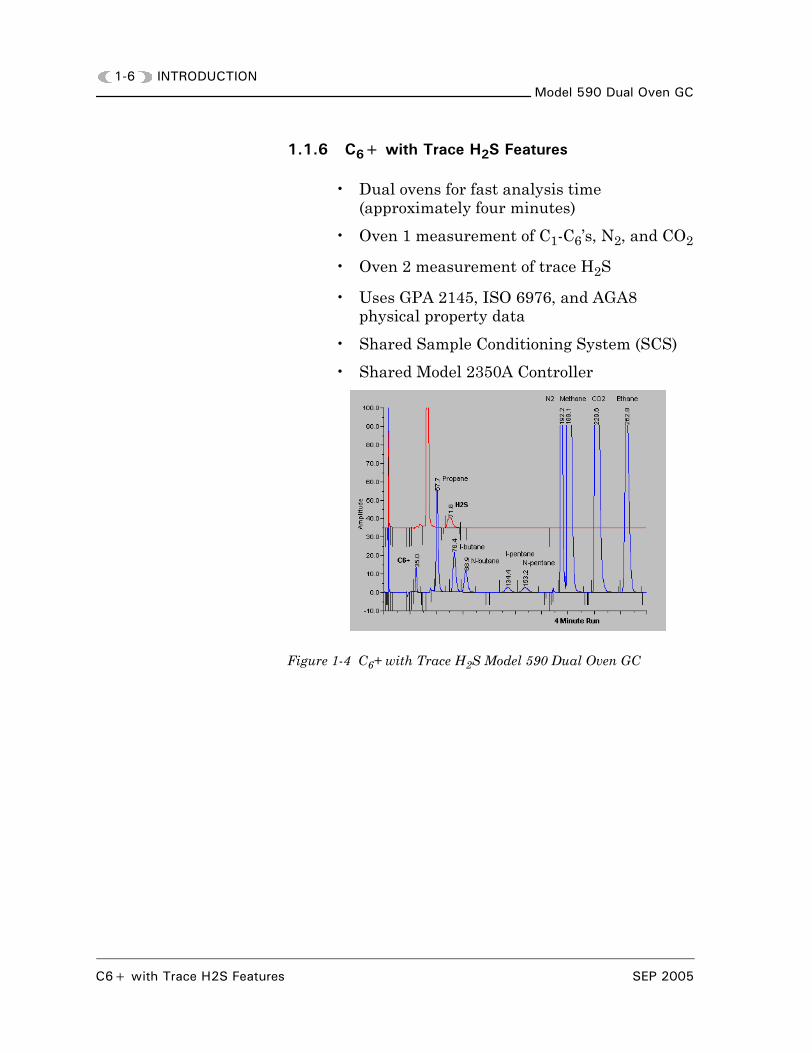
1.1.6 C6+ with Trace H2S Features
• Dual ovens for fast analysis time (approximately four minutes)
• Oven 1 measurement of C1-C6’s, N2, and CO2
• Oven 2 measurement of trace H2S
• Uses GPA 2145, ISO 6976, and AGA8 physical property data
• Shared Sample Conditioning System (SCS)
• Shared Model 2350A Controller
Figure 1-4 C6+ with Trace H2S Model 590 Dual Oven GC
C6+ with Trace H2S Features SEP 2005
INTRODUCTION 1-7Model 590 Dual Oven GC
1.1.7 C6+ with Trace H2S Applications
• Compositional analysis of pipeline gas(C1-C6+, N2, CO2, and H2S)
• Calculates heating value, specific gravity, and compressibility
• Measures trace H2S in oven 2. ± 3PPM over complete temperature range. ± 2PPM when in controlled environment.
• BTU measurement for custody transfer
• H2S critical measurement in regards to personal safety, corrosion control, and contractual agreements
• Dual chromatography allows for trace measurement of H2S
1.1.8 Software Compatibility
The Model 590 Dual Oven GC uses the MON2000 Software program as the interface from the PC to the 2350A Controller. Refer to the MON2000 Software for Gas Chromatographs User Manual (P/N 3-9000-522) for operations, maintenance, and trouble-shooting details.
SEP 2005 C6+ with Trace H2S Applications

1-8 INTRODUCTIONModel 590 Dual Oven GC
This page is intentionally left blank.
Software Compatibility SEP 2005
INSTALLATION 2-1Model 590 Dual Oven GC
2
INSTALLATION
2.1 INSTALLING THE DUAL OVEN GC UNIT
The Dual Oven GC is a typical single GC installation with the exception of the interconnect wiring. This section provides instructions for installing the Model 590 Dual Oven GC system.
Refer to one of the following Gas Chromatograph Hardware Reference Manuals:
• Model 500 GC (P/N 3-9000-537)
• Model 500 GC (P/N 3-9000-567)
and become familiar with all warnings, precautions, and notes for hazardous environment and electrical wiring installation procedures.
2.1.1 Dual Oven Analyzer Installation
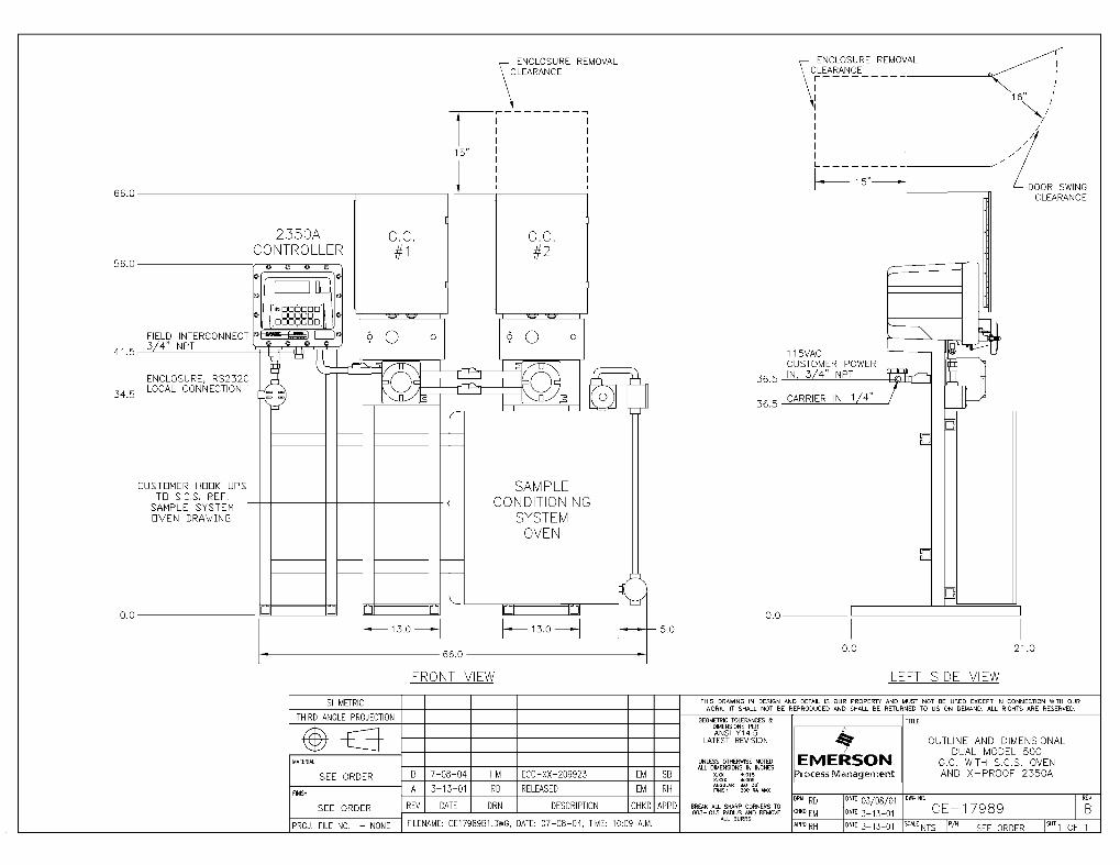
Refer to drawing (P/N CE-17989) and see Section 2.1, above, for a list of GC Hardware Reference manuals.
Select a site that allows adequate access space for performing maintenance and adjustments.
Allow a minimum of 16 inches (40.64 cm) in front of the unit and 15 inches (38.1 cm) in the rear of the unit for clearance. Allow a minimum of 66 inches (167.64 cm) height clearance.
SEP 2005 Dual Oven Analyzer Installation
2-2 INSTALLATIONModel 590 Dual Oven GC
2.1.2 Dual Oven GC Wiring Guide
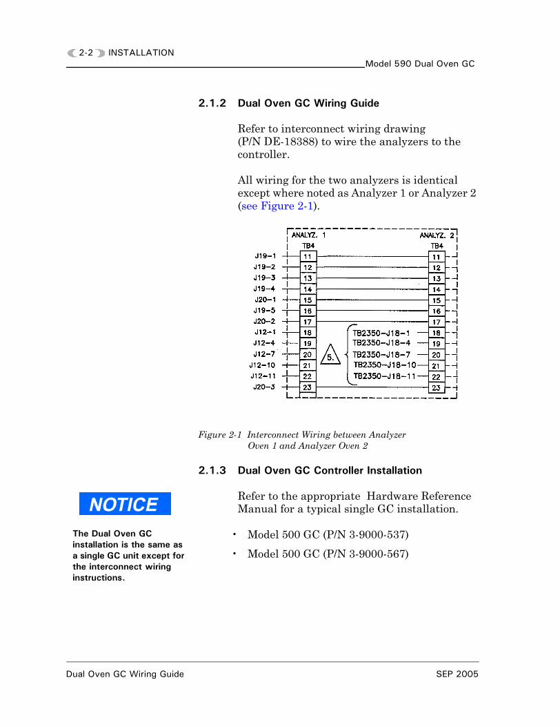
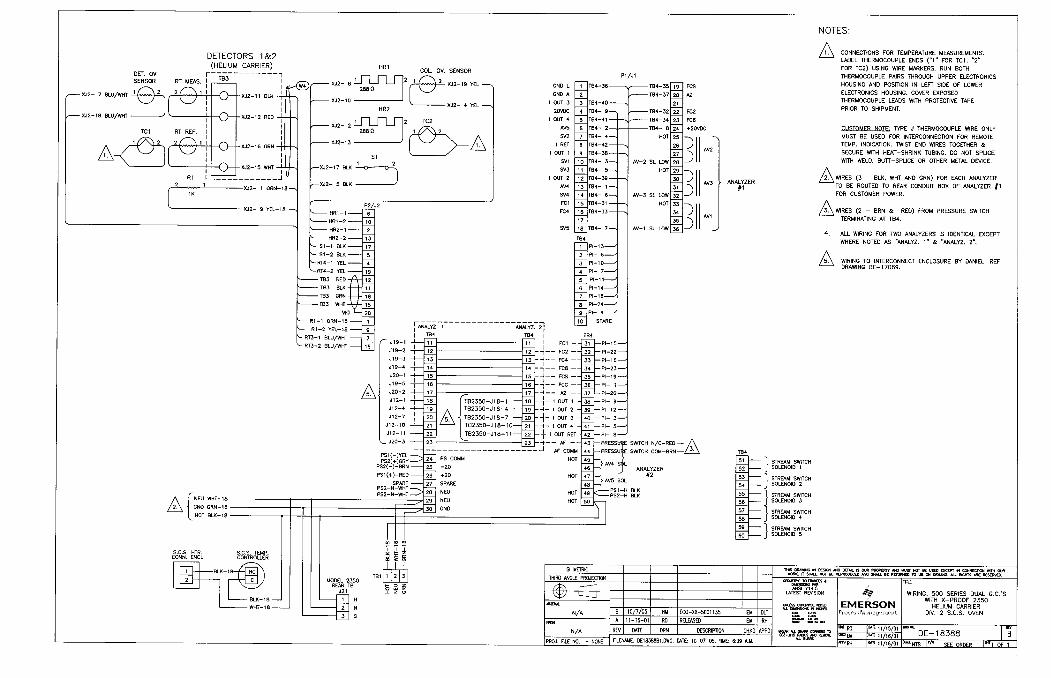
Refer to interconnect wiring drawing (P/N DE-18388) to wire the analyzers to the controller.
All wiring for the two analyzers is identical except where noted as Analyzer 1 or Analyzer 2 (see Figure 2-1).
Figure 2-1 Interconnect Wiring between Analyzer Oven 1 and Analyzer Oven 2
2.1.3 Dual Oven GC Controller Installation
Refer to the appropriate Hardware Reference Manual for a typical single GC installation.
• Model 500 GC (P/N 3-9000-537)
• Model 500 GC (P/N 3-9000-567)
The Dual Oven GC installation is the same as a single GC unit except for the interconnect wiring instructions.
Dual Oven GC Wiring Guide SEP 2005
INSTALLATION 2-3Model 590 Dual Oven GC
2.1.4 Controller to Dual Oven Analyzer Wiring
To make wiring connections between the GC Controller and the Analyzer (see Appendix AP/N DE-20782).
DANGER TO PERSONNEL AND EQUIPMENT
Do not operate a PC in a hazardous environment. Do not make or break front panel wiring connections.
In a hazardous environment, ensure that the field connections to the Analyzer or GC Controller (including serial port) are made through explosion-proof conduit or flameproof glands.
Failure to do so may result in injury to personnel or cause damage to the equipment.
SEP 2005 Controller to Dual Oven Analyzer Wiring
2-4 INSTALLATIONModel 590 Dual Oven GC
This page is intentionally left blank.
Controller to Dual Oven Analyzer Wiring SEP 2005
OPERATIONS 3-1Model 590 Dual GC
3
OPERATIONS
3.1 MODEL 590 DUAL GC SYSTEM OPERATIONS
Refer to one of the following Gas Chromatograph Hardware Reference Manuals for user interface when connected to the Model 590 Dual GC system from a PC and when using the GC Controller’s built-in keyboard and liquid crystal display (LCD) in hazardous environments.
• Model 500 GC (P/N 3-9000-537)
• Model 500 GC (P/N 3-9000-567)
Become familiar with all warnings, precautions, and notes for hazardous environment and electrical wiring installation procedures.
SEP 2005
3-2 OPERATIONSModel 590 Dual GC
This page is intentionally left blank.
SEP 2005
ENGINEERING DRAWINGS A-1Model 590 Dual Oven GC
A
APPENDIX,A ENGINEERING DRAWINGS
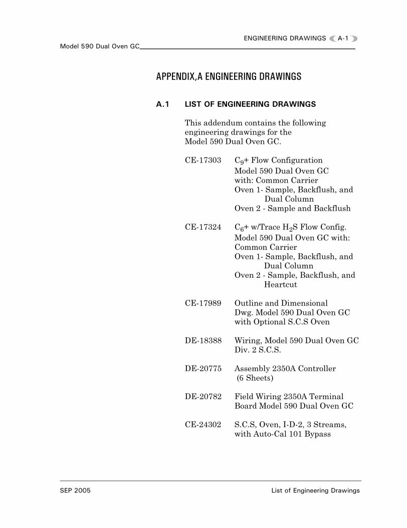
A.1 LIST OF ENGINEERING DRAWINGS
This addendum contains the following engineering drawings for theModel 590 Dual Oven GC.
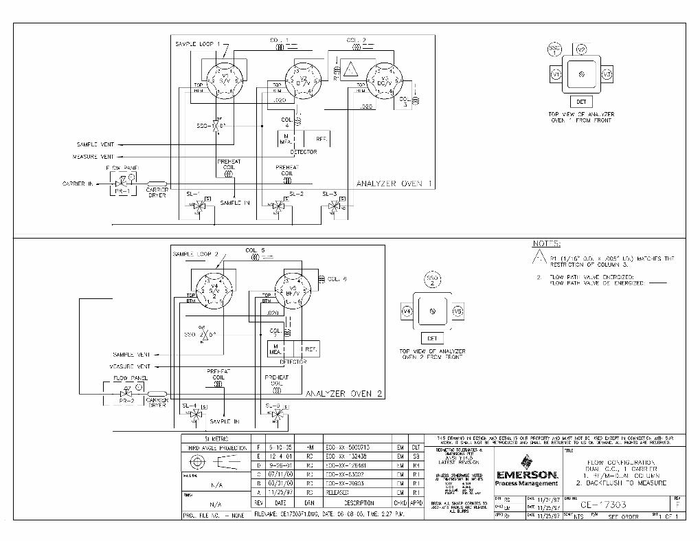
CE-17303 C9+ Flow Configuration Model 590 Dual Oven GC with: Common CarrierOven 1- Sample, Backflush, and
Dual ColumnOven 2 - Sample and Backflush
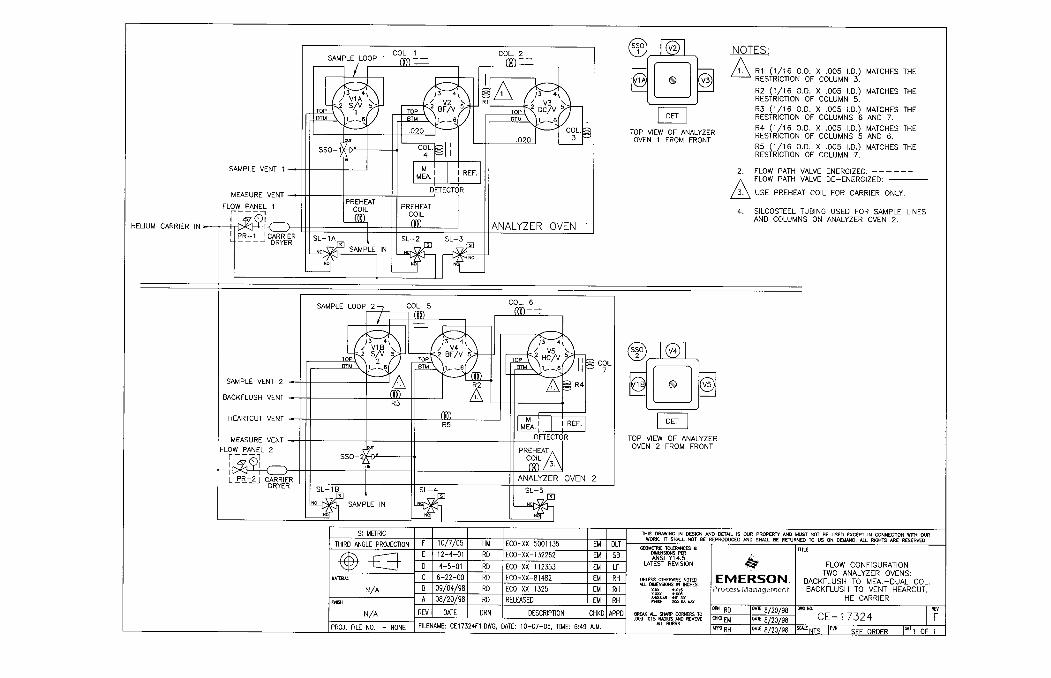
CE-17324 C6+ w/Trace H2S Flow Config.Model 590 Dual Oven GC with:Common CarrierOven 1- Sample, Backflush, and
Dual ColumnOven 2 - Sample, Backflush, and
Heartcut
CE-17989 Outline and Dimensional Dwg. Model 590 Dual Oven GCwith Optional S.C.S Oven
DE-18388 Wiring, Model 590 Dual Oven GCDiv. 2 S.C.S.
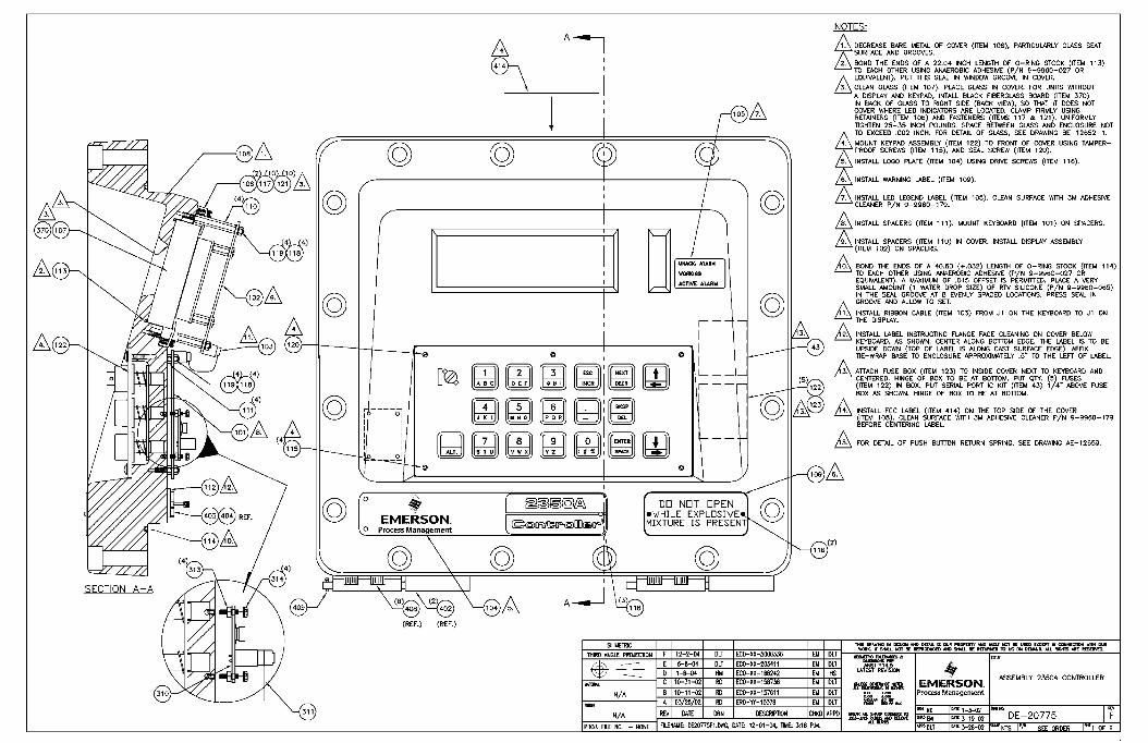
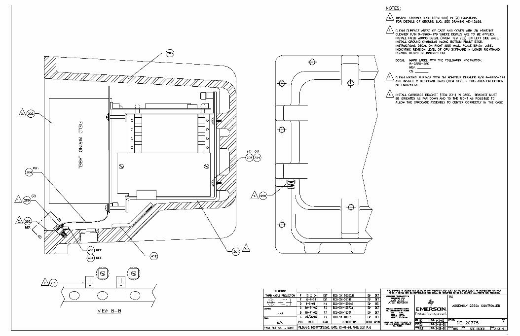
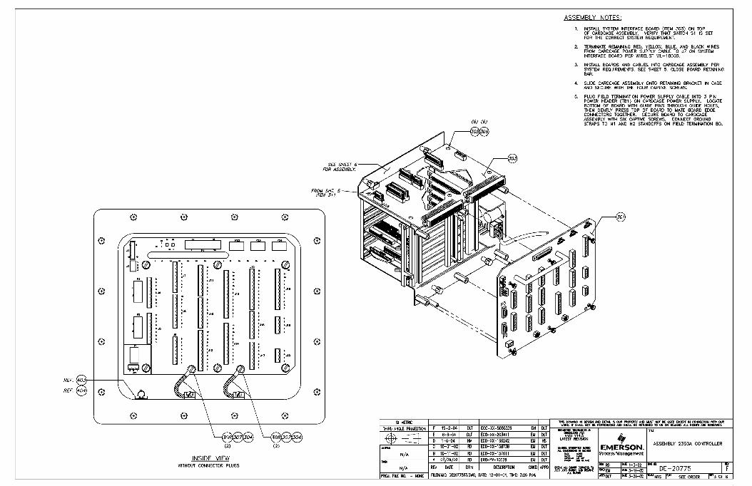
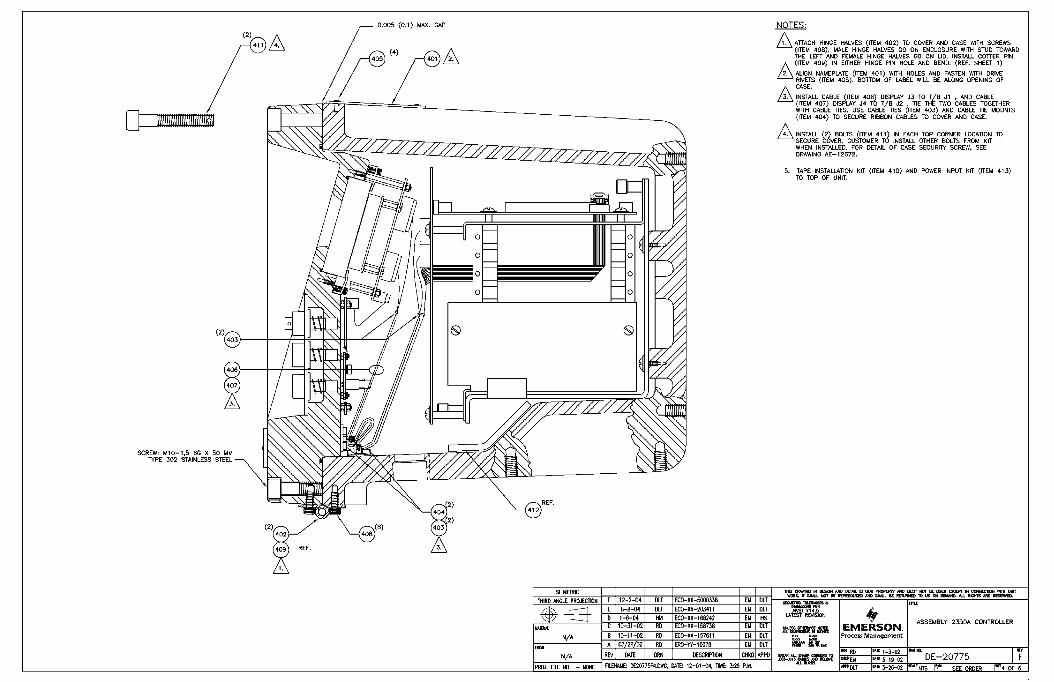
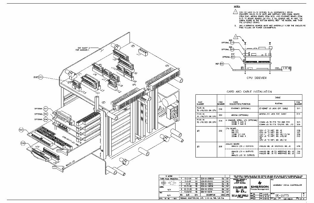
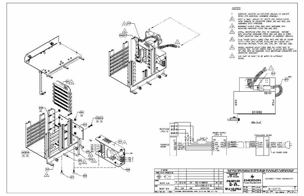
DE-20775 Assembly 2350A Controller (6 Sheets)
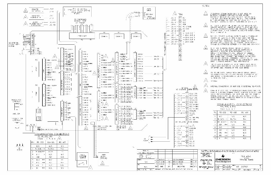
DE-20782 Field Wiring 2350A TerminalBoard Model 590 Dual Oven GC
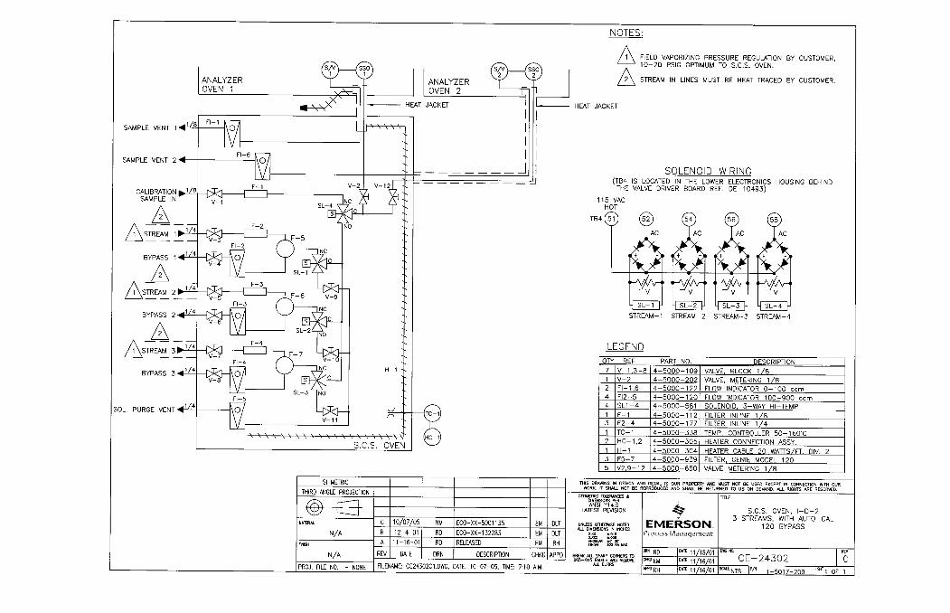
CE-24302 S.C.S, Oven, I-D-2, 3 Streams,with Auto-Cal 101 Bypass
SEP 2005 List of Engineering Drawings
A-2 ENGINEERING DRAWINGSModel 590 Dual Oven GC
This page is intentionally left blank.
List of Engineering Drawings SEP 2005
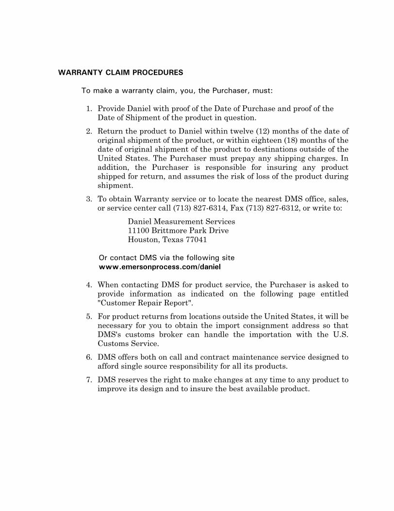
WARRANTY CLAIM PROCEDURES
To make a warranty claim, you, the Purchaser, must:
1. Provide Daniel with proof of the Date of Purchase and proof of the Date of Shipment of the product in question.
2. Return the product to Daniel within twelve (12) months of the date oforiginal shipment of the product, or within eighteen (18) months of thedate of original shipment of the product to destinations outside of theUnited States. The Purchaser must prepay any shipping charges. Inaddition, the Purchaser is responsible for insuring any productshipped for return, and assumes the risk of loss of the product duringshipment.
3. To obtain Warranty service or to locate the nearest DMS office, sales,or service center call (713) 827-6314, Fax (713) 827-6312, or write to:
Daniel Measurement Services11100 Brittmore Park DriveHouston, Texas 77041
Or contact DMS via the following sitewww.emersonprocess.com/daniel
4. When contacting DMS for product service, the Purchaser is asked toprovide information as indicated on the following page entitled"Customer Repair Report".
5. For product returns from locations outside the United States, it will benecessary for you to obtain the import consignment address so thatDMS's customs broker can handle the importation with the U.S.Customs Service.
6. DMS offers both on call and contract maintenance service designed toafford single source responsibility for all its products.
7. DMS reserves the right to make changes at any time to any product toimprove its design and to insure the best available product.

This page is intentionally left blank.
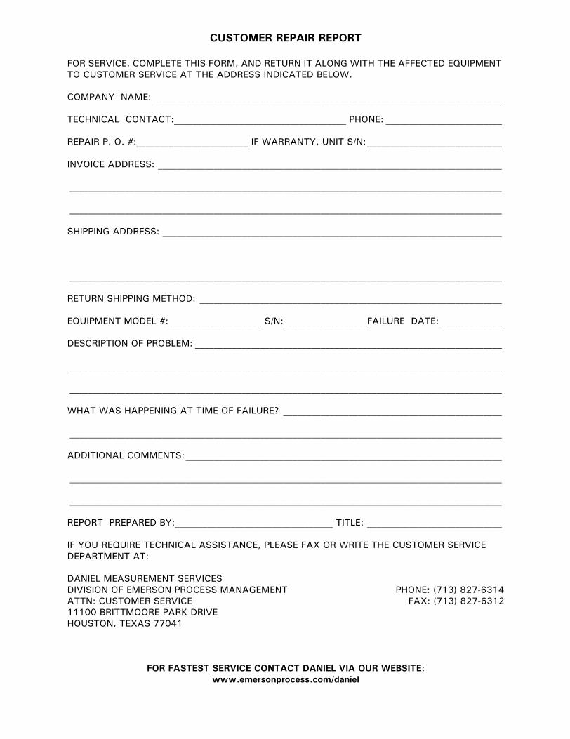
CUSTOMER REPAIR REPORT
FOR SERVICE, COMPLETE THIS FORM, AND RETURN IT ALONG WITH THE AFFECTED EQUIPMENT TO CUSTOMER SERVICE AT THE ADDRESS INDICATED BELOW.
COMPANY NAME: ___________________________________________________________________________
TECHNICAL CONTACT:_____________________________________ PHONE: _________________________
REPAIR P. O. #:________________________ IF WARRANTY, UNIT S/N:_____________________________
INVOICE ADDRESS: __________________________________________________________________________
_____________________________________________________________________________________________
_____________________________________________________________________________________________
SHIPPING ADDRESS: _________________________________________________________________________
_____________________________________________________________________________________________
RETURN SHIPPING METHOD: _________________________________________________________________
EQUIPMENT MODEL #:____________________ S/N:__________________FAILURE DATE: _____________
DESCRIPTION OF PROBLEM: __________________________________________________________________
_____________________________________________________________________________________________
_____________________________________________________________________________________________
WHAT WAS HAPPENING AT TIME OF FAILURE? _______________________________________________
_____________________________________________________________________________________________
ADDITIONAL COMMENTS:____________________________________________________________________
_____________________________________________________________________________________________
_____________________________________________________________________________________________
REPORT PREPARED BY:__________________________________ TITLE: _____________________________
IF YOU REQUIRE TECHNICAL ASSISTANCE, PLEASE FAX OR WRITE THE CUSTOMER SERVICE DEPARTMENT AT:
DANIEL MEASUREMENT SERVICESDIVISION OF EMERSON PROCESS MANAGEMENT PHONE: (713) 827-6314ATTN: CUSTOMER SERVICE FAX: (713) 827-631211100 BRITTMOORE PARK DRIVEHOUSTON, TEXAS 77041
FOR FASTEST SERVICE CONTACT DANIEL VIA OUR WEBSITE:www.emersonprocess.com/daniel


This page is intentionally left blank.
Daniel Measurement and Control, Inc., Daniel Measurement Services, Inc., and RosemountAnalytical Inc., Divisions of Emerson Process Management, reserves the right to makechanges to any of its products or services at any time without prior notification in order toimprove that product or service and to supply the best product or service possible.
www.emersonprocess.com