Embed Size (px)
Citation preview
ManualGlassfront Beverage Vender
Modols ON 2145
OperationServicePartsTroubleshootingManual
Dixiel~arcoS"i....-.
_,. In<.
'0,0--'"_. "" -...0:"
-~...,_...._ _-' =

Glassfront Beverage VenderModels DN 2145
Manual
2002 Bottle
•
1202 Can
1602 Bottle
These are the three most common shims used
Please see user manual for other shims and their usage
This machine requires shims to operate correctly
They are included inside the machine see images above
To identify which shim is for which product
Manufactured by
DiXiel~arco~~endl"9Systems
2
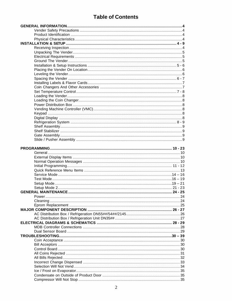
Table of Contents
GENERAL INFORMATION.....................................................................................................4 Vender Safety Precautions ..........................................................................................4 Product Identification ..................................................................................................4 Physical Characteristics ..............................................................................................4
INSTALLATION & SETUP ................................................................................................. 4 - 9 Receiving Inspection ...................................................................................................4 Unpacking The Vender................................................................................................5 Electrical Requirements ..............................................................................................5 Ground The Vender ....................................................................................................5 Installation & Setup Instructions .............................................................................. 5 - 6 Placing the Vender On Location...................................................................................6 Leveling the Vender....................................................................................................6 Spacing the Vender ............................................................................................... 6 - 7 Installing Labels & Flavor Cards...................................................................................7 Coin Changers And Other Accessories ........................................................................7 Set Temperature Control ........................................................................................ 7 - 8 Loading the Vender.....................................................................................................8 Loading the Coin Changer...........................................................................................8 Power Distribution Box ................................................................................................8 Vending Machine Controller (VMC)..............................................................................8 Keypad ......................................................................................................................8 Digital Display ............................................................................................................8 Refrigeration System ............................................................................................. 8 - 9 Shelf Assembly...........................................................................................................9 Shelf Stabilizer ...........................................................................................................9 Gate Assembly ...........................................................................................................9 Slide / Pusher Assembly .............................................................................................9
PROGRAMMING........................................................................................................... 10 - 23 General .................................................................................................................... 10 External Display Items .............................................................................................. 10 Normal Operation Messages ..................................................................................... 10 Initial Programming............................................................................................ 11 - 12 Quick Reference Menu Items .................................................................................... 13 Service Mode ....................................................................................................14 – 16 Test Mode .........................................................................................................16 – 19 Setup Mode.......................................................................................................19 – 21 Setup Mode 2.................................................................................................... 21 - 23
GENERAL MAINTENANCE ........................................................................................... 24 - 25 Power ...................................................................................................................... 24 Cleaning .................................................................................................................. 24 Eprom Replacement ................................................................................................. 25
MAJOR COMPONENT DESCRIPTION .......................................................................... 26 - 27 AC Distribution Box / Refrigeration DN55##/54##/2145............................................... 26 AC Distribution Box / Refrigeration Unit DN35## ......................................................... 27
ELECTRICAL DIAGRAMS & SCHEMATICS .................................................................. 28 - 29 MDB Controller Connections ..................................................................................... 28 Dual Sensor Board ................................................................................................... 29
TROUBLESHOOTING...................................................................................................30 – 39 Coin Acceptance ...................................................................................................... 30 Bill Acceptors ........................................................................................................... 30 Control Board ........................................................................................................... 30 All Coins Rejected .................................................................................................... 31 All Bills Rejected....................................................................................................... 32 Incorrect Change Dispensed ..................................................................................... 33 Selection Will Not Vend ............................................................................................. 34 Ice / Frost on Evaporator........................................................................................... 35 Condensate on Outside of Product Door .................................................................... 35 Compressor Will Not Stop ......................................................................................... 35
3
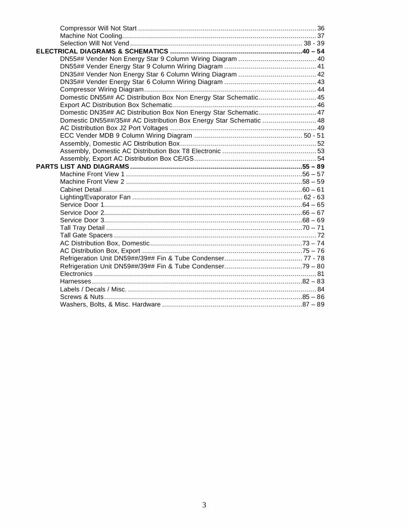
Compressor Will Not Start ......................................................................................... 36 Machine Not Cooling................................................................................................. 37 Selection Will Not Vend ...................................................................................... 38 - 39
ELECTRICAL DIAGRAMS & SCHEMATICS ..................................................................40 – 54 DN55## Vender Non Energy Star 9 Column Wiring Diagram ....................................... 40 DN55## Vender Energy Star 9 Column Wiring Diagram .............................................. 41 DN35## Vender Non Energy Star 6 Column Wiring Diagram ....................................... 42 DN35## Vender Energy Star 6 Column Wiring Diagram .............................................. 43 Compressor Wiring Diagram...................................................................................... 44 Domestic DN55## AC Distribution Box Non Energy Star Schematic............................. 45 Export AC Distribution Box Schematic........................................................................ 46 Domestic DN35## AC Distribution Box Non Energy Star Schematic............................. 47 Domestic DN55##/35## AC Distribution Box Energy Star Schematic ........................... 48 AC Distribution Box J2 Port Voltages ......................................................................... 49 ECC Vender MDB 9 Column Wiring Diagram ...................................................... 50 - 51 Assembly, Domestic AC Distribution Box.................................................................... 52 Assembly, Domestic AC Distribution Box T8 Electronic ............................................... 53 Assembly, Export AC Distribution Box CE/GS............................................................. 54
PARTS LIST AND DIAGRAMS ......................................................................................55 – 89 Machine Front View 1 ........................................................................................56 – 57 Machine Front View 2 ........................................................................................58 – 59 Cabinet Detail ....................................................................................................60 – 61 Lighting/Evaporator Fan ..................................................................................... 62 - 63 Service Door 1...................................................................................................64 – 65 Service Door 2...................................................................................................66 – 67 Service Door 3...................................................................................................68 – 69 Tall Tray Detail ..................................................................................................70 – 71 Tall Gate Spacers ..................................................................................................... 72 AC Distribution Box, Domestic............................................................................73 – 74 AC Distribution Box, Export ................................................................................75 – 76 Refrigeration Unit DN59##/39## Fin & Tube Condenser....................................... 77 - 78 Refrigeration Unit DN59##/39## Fin & Tube Condenser.......................................79 – 80 Electronics ............................................................................................................... 81 Harnesses .........................................................................................................82 – 83 Labels / Decals / Misc. .............................................................................................. 84 Screws & Nuts...................................................................................................85 – 86 Washers, Bolts, & Misc. Hardware ......................................................................87 – 89
VENDER SAFETY PRECAUTIONS
IMPORTANT NOTE: This machine should not beused to vend perishableproducts without the HealthControl Kit (622,010,2Ox.x4)installed. If you wish to vendperishable products, pleasecontact Dixie-Narco forassistance.
Please read this manual in its entirety. This serviceinformation is intended for use by a qualified servicetechnician who is familiar with proper and safeprocedures to be followed when repairing, replacing oradjusting any Dixie-Narco vender components. Allrepairs should be performed by a qualified servicetechnician who is equipped with the proper tools andreplacement components, using genuine Dixie-Narcofactory parts.
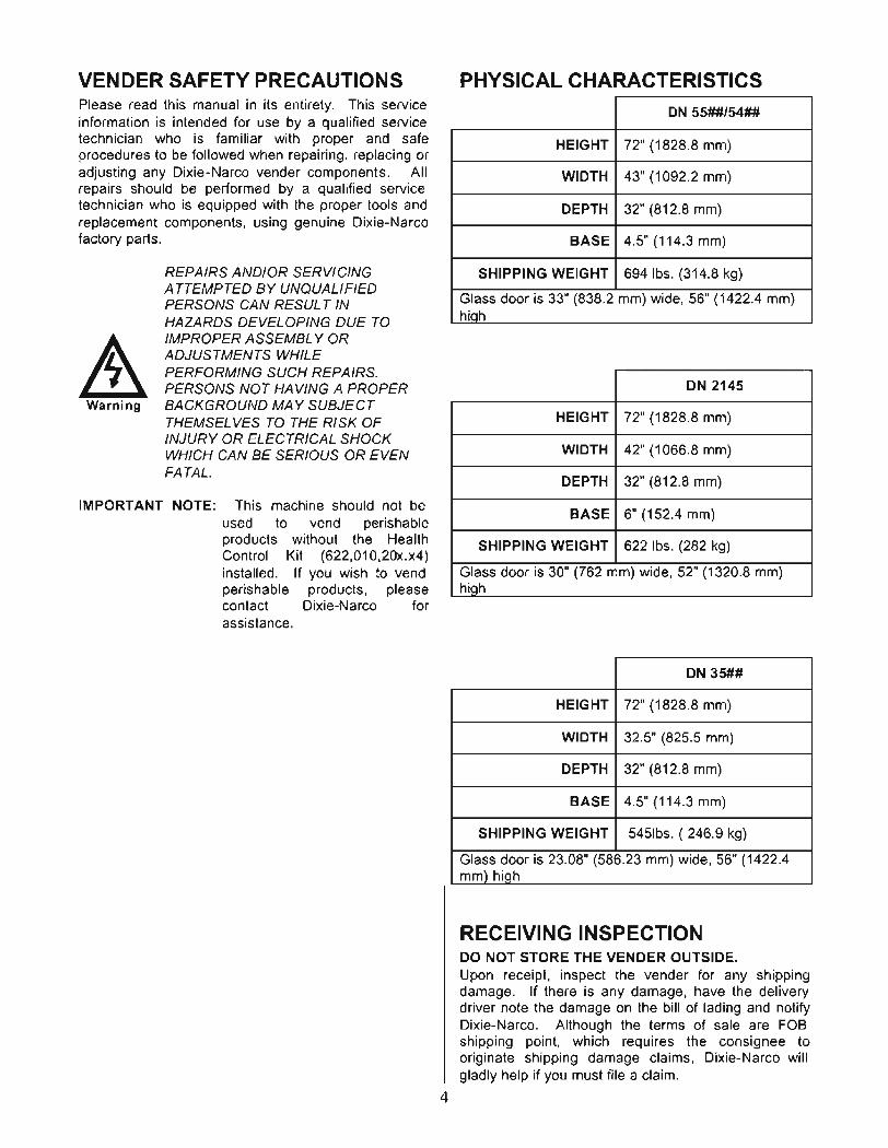
PHYSICAL CHARACTERISTICS
DN 55##/54##
HEIGHT 72" (1828.8 mm)
WIDTH 43" (1092.2 mm)
DEPTH 32" (812.8 mm)
BASE 4.5" (114.3 mm)
SHIPPING WEIGHT 694 lbs. (314.8 kg)
Glass door is 33" (838.2 mm) wide, 56" (1422.4 mm)hiah
DN 2145
HEIGHT 72" (1828.8 mm)
WIDTH 42" (1066.8 mm)
DEPTH 32" (812.8 mm)
BASE 6" (152.4 mm)
SHIPPING WEIGHT 622 lbs. (282 kg)
Glass door is 30" (762 mm) wide, 52" (1320.8 mm)high
DN 35##
HEIGHT 72" (1828.8 mm)
WIDTH 32.5" (825.5 mm)
DEPTH 32" (812.8 mm)
BASE 4.5" (114.3 mm)
SHIPPING WEIGHT 5451bs. ( 246.9 kg)
Glass door is 23.08" (586.23 mm) wide, 56" (1422.4mm) hiQh
RECEIVING INSPECTIONDO NOT STORE THE VENDER OUTSIDE.Upon receipt, inspect the vender for any shippingdamage. If there is any damage, have the deliverydriver note the damage on the bill of lading and notifyDixie-Narco. Although the terms of sale are FOBshipping point, which requires the consignee tooriginate shipping damage claims, Dixie-Narco willgladly help if you must file a claim.
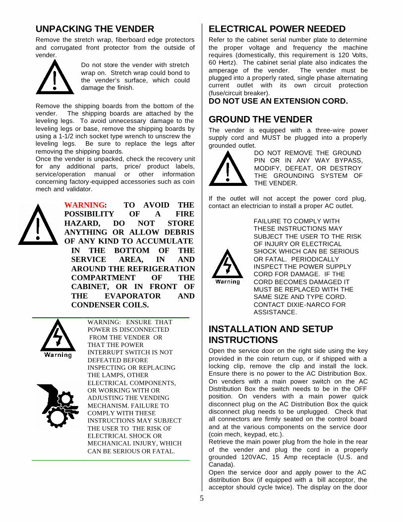
REPAIRS AND/OR SERVICINGATTEMPTED BY UNQUALIFIEDPERSONS CAN RESUL TINHAZARDS DEVELOPING DUE TOIMPROPER ASSEMBL Y ORADJUSTMENTS WHILEPERFORMING SUCH REPAIRS.PERSONS NOT HAVING A PROPERBACKGROUND MA Y SUBJECTTHEMSEL VES TO THE RISK OFINJURY OR ELECTRICAL SHOCKWHICH CAN BE SERIOUS OR EVENFATAL.
Warning
4
5
UNPACKING THE VENDER Remove the stretch wrap, fiberboard edge protectors and corrugated front protector from the outside of vender.
Do not store the vender with stretch wrap on. Stretch wrap could bond to the vender’s surface, which could damage the finish.
Remove the shipping boards from the bottom of the vender. The shipping boards are attached by the leveling legs. To avoid unnecessary damage to the leveling legs or base, remove the shipping boards by using a 1-1/2 inch socket type wrench to unscrew the leveling legs. Be sure to replace the legs after removing the shipping boards. Once the vender is unpacked, check the recovery unit for any additional parts, price/ product labels, service/operation manual or other information concerning factory-equipped accessories such as coin mech and validator.
WARNING: TO AVOID THE POSSIBILITY OF A FIRE HAZARD, DO NOT STORE ANYTHING OR ALLOW DEBRIS OF ANY KIND TO ACCUMULATE
IN THE BOTTOM OF THE SERVICE AREA, IN AND AROUND THE REFRIGERATION COMPARTMENT OF THE CABINET, OR IN FRONT OF THE EVAPORATOR AND CONDENSER COILS.
WARNING: ENSURE THAT POWER IS DISCONNECTED FROM THE VENDER OR THAT THE POWER INTERRUPT SWITCH IS NOT DEFEATED BEFORE INSPECTING OR REPLACING THE LAMPS, OTHER ELECTRICAL COMPONENTS, OR WORKING WITH OR ADJUSTING THE VENDING MECHANISM. FAILURE TO COMPLY WITH THESE INSTRUCTIONS MAY SUBJECT THE USER TO THE RISK OF ELECTRICAL SHOCK OR MECHANICAL INJURY, WHICH CAN BE SERIOUS OR FATAL.
ELECTRICAL POWER NEEDED Refer to the cabinet serial number plate to determine the proper voltage and frequency the machine requires (domestically, this requirement is 120 Volts, 60 Hertz). The cabinet serial plate also indicates the amperage of the vender. The vender must be plugged into a properly rated, single phase alternating current outlet with its own circuit protection (fuse/circuit breaker). DO NOT USE AN EXTENSION CORD.
GROUND THE VENDER The vender is equipped with a three-wire power supply cord and MUST be plugged into a properly grounded outlet.
DO NOT REMOVE THE GROUND PIN OR IN ANY WAY BYPASS, MODIFY, DEFEAT, OR DESTROY THE GROUNDING SYSTEM OF THE VENDER.
If the outlet will not accept the power cord plug, contact an electrician to install a proper AC outlet.
FAILURE TO COMPLY WITH THESE INSTRUCTIONS MAY SUBJECT THE USER TO THE RISK OF INJURY OR ELECTRICAL SHOCK WHICH CAN BE SERIOUS OR FATAL. PERIODICALLY INSPECT THE POWER SUPPLY CORD FOR DAMAGE. IF THE CORD BECOMES DAMAGED IT MUST BE REPLACED WITH THE SAME SIZE AND TYPE CORD. CONTACT DIXIE-NARCO FOR ASSISTANCE.
INSTALLATION AND SETUP INSTRUCTIONS Open the service door on the right side using the key provided in the coin return cup, or if shipped with a locking clip, remove the clip and install the lock. Ensure there is no power to the AC Distribution Box. On venders with a main power switch on the AC Distribution Box the switch needs to be in the OFF position. On venders with a main power quick disconnect plug on the AC Distribution Box the quick disconnect plug needs to be unplugged. Check that all connectors are firmly seated on the control board and at the various components on the service door (coin mech, keypad, etc.). Retrieve the main power plug from the hole in the rear of the vender and plug the cord in a properly grounded 120VAC, 15 Amp receptacle (U.S. and Canada). Open the service door and apply power to the AC distribution Box (if equipped with a bill acceptor, the acceptor should cycle twice). The display on the door
6
should scroll the message “USE EXACT CHANGE”, the fluorescent lamp should be lit and the cooling unit should start. If the display scrolls “OUT OF SERVICE”, or the cooling unit fails to start, refer to the TROUBLESHOOTING FLOWCHARTS beginning on page 30.
SERVICE NOTE Battery Backup The battery backup is used to retain information programmed in the system (pricing, time, date, etc.). in case of power interruptions, or any time the main power is off. When the vender is shipped, the battery is connected and memory is being maintained. If the vender is to be stored for long periods of time, disconnecting the battery is recommended. The following steps will guide you through this procedure: Open the service door and unplug the main power harness located on the front of the power box.
1. Locate the main control board mounted on the right side wall.
2. On controllers with a cover, remove the screw securing the cover to the board.
3. The backup system jumper is located just below the battery near the center of the board (refer to figure 1, page 25).
4. Remove the jumper covering the pins and place it on only one pin for storage.
5. Reinstall the cover, if used, and tighten the screw.
6. Reverse this procedure to connect the battery.
PLACING THE VENDER ON LOCATION
!! CAUTION !!
DO NOT TRANSPORT THE VENDER TO OR FROM THE LOCATION LOADED WITH PRODUCT OR DAMAGE TO THE VENDER MAY RESULT.
The vender is intended for INDOOR USE ONLY. It should be kept out of direct sunlight and away form any heat source. The vender must be on a solid, flat and level surface. Ensure the flooring can bear the weight load of a fully loaded vender (approximately 1150 lbs.). The vender must be positioned close enough to an electrical outlet so that an extension cord is not required. If the machine will be subject to user misuse or vandalism, it is recommended that the vender be secured to the floor or wall as described in Dixie-Narco Technical
Bulletin 344. Due to the large size and weight of the Vender, never attempt to move the Vender with a Hand Truck or Stair Climber. Use a pallet jack or Vender/Cooler Dollies at all times when moving the Vender. The vender should never be slid or pushed in place. Never side load the leveling legs; doing so will cause damage to the legs. Do not transport the vender to or from customer locations loaded with product, as damage may result due to excessive weight. Call the Dixie-Narco Technical Service Department or your Dixie-Narco Representative for assistance.
LEVEL THE VENDER Adjust the front leveling legs, ensuring that an even gap exists between the glass door and the top security angle and receiver box, and then level the cabinet front to rear. A carpenter’s level will help verify that the vender is level. Leveling legs are adjusted using a wrench or socket 1 ½” in size. If the vender is to be used in a bank of equipment, check the top and sides for proper alignment. If you are unable to properly level the vender, select an alternate location. NEVER PLACE OBJECTS UNDER THE LEVELING LEGS OF THE VENDER
DANGER
THE VENDER MUST BE PROPERLY LOCATED AND LEVELED. IF THE MACHINE WILL BE SUBJECT TO USER MISUSE OR VANDALISM IT IS RECOMMENDED THAT THE VENDER BE SECURED TO THE FLOOR OR WALL AS DESCRIBED IN DIXIE-NARCO TECHNICAL BULLETIN 344 TO MINI MIZE THE RISK OF INJURY OR DEATH FROM TIPPING. CALL THE DIXIE-NARCO TECHNICAL SERVICE DEPARTMENT OR YOUR DIXIE-NARCO REPRESENTATIVE FOR ASSISTANCE.
SPACE THE VENDER Do not block the rear of the vender. Maintain a minimum of 4 inches (10 cm) from the wall to ensure adequate airflow to the condenser and compressor. At the front of the vender, make sure that nothing obstructs the air intake at the bottom of the service door and cabinet. At the rear of the vender, make sure nothing obstructs the air exhaust at the bottom of the cabinet.
7
WARNING
TO AVOID THE POSSIBILITY OF A FIRE HAZARD, DO NOT STORE ANYTHING OR ALLOW DEBRIS OF ANY KIND TO ACCUMULATE IN THE BOTTOM OF THE DOOR, IN THE BOTTOM OF THE SERVICE AREA, IN AND AROUND THE REFRIGERATION COMPARTMENT OF THE CABINET, OR IN FRONT OF THE EVAPORATOR AND CONDENSER COILS.
INSTALLING PRICE LABELS Pricing labels included in the literature package kit. They are double sided and range in price from .25 to 9.95. The price labels are inserted at the top of the front knuckle of each release mechanism. Remove the pricing label sheets from the service manual package and gently remove the label corresponding to the vend price of each selection by tearing at the perforation. The label is inserted between the grooves at the top of the front knuckle by slightly bending sides of the label toward the front of the vender being careful not to crease the label. Once inserted, push the label firmly against the front of the knuckle. This will insure the label is locked in place and will not fall out during normal operation of the vend mechanism.
INSTALLING FLAVOR CARDS For problem free vending, it is necessary to load the venders columns consistently with same product every time the vender is filled. To ensure consistent loading, flavor cards are included for the slide assemblies with every vender and should be installed into the product pusher to designate to the route driver which product the column is set for. To install the flavor card, simply detach it from the sheet at the perforation and slide it into the slots in the product pusher.
COIN CHANGERS & OTHER ACCESSORIES The vender must have an MDB coin changer installed and can have an MDB bill acceptor installed as well. If the MDB coin changer and other MDB accessories are not factory installed, refer to the instructions received form the manufacturer of the MDB coin changer and other MDB accessories for proper set-up and installation. The vender will support the following Domestic MDB coin changers:
Coinco 9302GX, USG-701 Quantum Mars TRC-6510, TRC-6512, TRC-4010 Conlux CCM-5G 1-2-3-4-5
The vender will support the following domestic MDB Bill validators:
Coinco BA-30 B, BA-50B Coinco Mag 50 Mars VN 2512 Conlux NBM-3000 Series The vender will support the following MDB card readers: Debitek VMC LTD Danyl Schlumberger Fage Diebold Systems Jofemar AT&T Campus Wide Evend.net Danyl Smartcard The above listed peripherals indicate units that have been tested by Dixie-Narco at the time of printing of this manual and are not all-inclusive. For information regarding other types not listed here, please contact Dixie-Narco Technical Service Department.
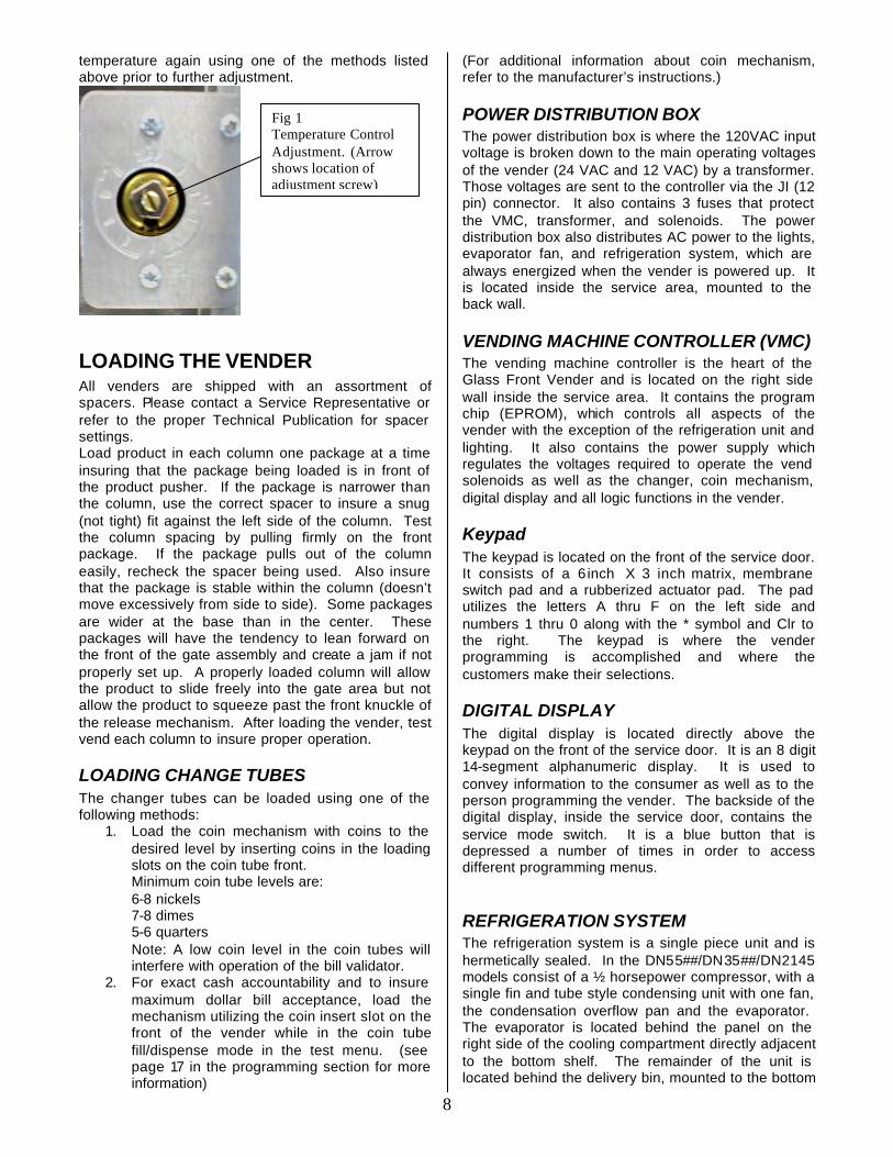
SETTING THE TEMPERATURE CONTROL This vender is equipped with a manual thermostat. It is located on the power distribution box inside the service area. This thermostat is factory pre-set to maintain a cabinet temperature of 33 to 38 degrees Fahrenheit (1 to 3 degrees centigrade), however, occasional adjustment may become necessary. It is also a good practice to ensure the proper operating temperature prior to installing the vender on location. To set the temperature, apply power to the vender and allow it to run for several hours with the glass door closed or until the minimum cabinet temperature is achieved. Then, using one of the methods below, verify the temperature inside the cabinet:
1. If your vender is equipped with an electronic temperature sensor, use the keypad on the service door to show cabinet temperature in Fahrenheit by pressing the F key followed by the asterisk (*) key or in Centigrade by pressing the C key followed by the asterisk key. The temperature will be shown on the digital display located on the front of the service door.
2. If your vender is not equipped with a temperature sensor, place a thermometer in the center of the C shelf when vender is first powered up. Make sure the thermometer is placed in a location that permits reading the temperature with the glass door closed. This will prevent the introduction of warm, ambient air.
Adjustments are made by turning the screw in the center of the control (Shown in fig. 1) clockwise for colder product or counterclockwise for warmer product. It is recommended that the control screw be adjusted in very small increments allowing the refrigeration unit to cycle off and then verifying the
8
temperature again using one of the methods listed above prior to further adjustment.
LOADING THE VENDER All venders are shipped with an assortment of spacers. Please contact a Service Representative or refer to the proper Technical Publication for spacer settings. Load product in each column one package at a time insuring that the package being loaded is in front of the product pusher. If the package is narrower than the column, use the correct spacer to insure a snug (not tight) fit against the left side of the column. Test the column spacing by pulling firmly on the front package. If the package pulls out of the column easily, recheck the spacer being used. Also insure that the package is stable within the column (doesn’t move excessively from side to side). Some packages are wider at the base than in the center. These packages will have the tendency to lean forward on the front of the gate assembly and create a jam if not properly set up. A properly loaded column will allow the product to slide freely into the gate area but not allow the product to squeeze past the front knuckle of the release mechanism. After loading the vender, test vend each column to insure proper operation.
LOADING CHANGE TUBES The changer tubes can be loaded using one of the following methods:
1. Load the coin mechanism with coins to the desired level by inserting coins in the loading slots on the coin tube front. Minimum coin tube levels are: 6-8 nickels 7-8 dimes 5-6 quarters Note: A low coin level in the coin tubes will interfere with operation of the bill validator.
2. For exact cash accountability and to insure maximum dollar bill acceptance, load the mechanism utilizing the coin insert slot on the front of the vender while in the coin tube fill/dispense mode in the test menu. (see page 17 in the programming section for more information)
(For additional information about coin mechanism, refer to the manufacturer’s instructions.)
POWER DISTRIBUTION BOX The power distribution box is where the 120VAC input voltage is broken down to the main operating voltages of the vender (24 VAC and 12 VAC) by a transformer. Those voltages are sent to the controller via the JI (12 pin) connector. It also contains 3 fuses that protect the VMC, transformer, and solenoids. The power distribution box also distributes AC power to the lights, evaporator fan, and refrigeration system, which are always energized when the vender is powered up. It is located inside the service area, mounted to the back wall.
VENDING MACHINE CONTROLLER (VMC) The vending machine controller is the heart of the Glass Front Vender and is located on the right side wall inside the service area. It contains the program chip (EPROM), which controls all aspects of the vender with the exception of the refrigeration unit and lighting. It also contains the power supply which regulates the voltages required to operate the vend solenoids as well as the changer, coin mechanism, digital display and all logic functions in the vender.
Keypad The keypad is located on the front of the service door. It consists of a 6 inch X 3 inch matrix, membrane switch pad and a rubberized actuator pad. The pad utilizes the letters A thru F on the left side and numbers 1 thru 0 along with the * symbol and Clr to the right. The keypad is where the vender programming is accomplished and where the customers make their selections.
DIGITAL DISPLAY The digital display is located directly above the keypad on the front of the service door. It is an 8 digit 14-segment alphanumeric display. It is used to convey information to the consumer as well as to the person programming the vender. The backside of the digital display, inside the service door, contains the service mode switch. It is a blue button that is depressed a number of times in order to access different programming menus.
REFRIGERATION SYSTEM The refrigeration system is a single piece unit and is hermetically sealed. In the DN55##/DN35##/DN2145 models consist of a ½ horsepower compressor, with a single fin and tube style condensing unit with one fan, the condensation overflow pan and the evaporator. The evaporator is located behind the panel on the right side of the cooling compartment directly adjacent to the bottom shelf. The remainder of the unit is located behind the delivery bin, mounted to the bottom
Fig 1 Temperature Control Adjustment. (Arrow shows location of adjustment screw)
9
of the cabinet. This unit is designed for easy removal and replacement from the front of the vender as a complete assembly. An electronic thermostat regulates the cabinet temperature. The bulb of the thermostat is attached to the evaporator coils and reads the temperature of the refrigerant inside the coil.
SHELF ASSEMBLY Typically, there are 5 shelf assemblies in every vender; however, this can vary depending upon the configuration specified at the time of ordering. Each can/bottle shelf consists of 6, 8, or 9 columns. Each shelf is capable of holding a variety of products. The shelf assembly consists of the tray, where all of the following parts are mounted: Gate assembly, shelf stabilizers and the slide/pusher assembly. Each snack/food shelf consists of 5, or 11 columns. Each shelf is capable of holding a variety of products. These items are discussed in detail below.
SHELF STABILIZERS Some packages will have the tendency to become unstable or bounce to the delivery bin when vended due to the design of the bottom of the package. This can lead to a product jam. The shelf stabilizer (the clear Lexan tab at the front of the tray) is used to prevent this from occurring by acting as an extension of the shelf. Unless otherwise specified at the time of ordering, shelf stabilizers are installed on the C and D shelves of the vender. The stabilizers that are installed on the C shelf can also be used on the A and B shelves as needed for product stability. The stabilizers installed on the D shelf must be used only on that shelf as they are longer and may interfere with the proper vending of a column. Do not use shelf stabilizers on the bottom tray as product jams may occur. To install the stabilizers, the slide assembly must first be removed from the column. The stabilizer is inserted on the bottom of the slide assembly by firmly pushing the square hole in the stabilizer onto the front locking tabs of the slide. The slide is then installed back into the column.
GATE ASSEMBLY (Can/Bottle Trays)
The gate assembly is mounted on the front portion of the tray assembly and contains the vending mechanism. Incorporated in the gate assembly are the front and rear knuckle assemblies as well as the product kicker. In standby operation, the front knuckle is in the blocking position, which holds the front (displayed product) in position to be vended. The rear knuckle assembly is in a flat position, which allows product to enter the gate area, and the kicker is flush to the rear knuckle assembly. A stainless steel pin is inserted through the rear most portion of the front knuckle assembly and connects to a solenoid plunger below the tray. When a selection is made, the solenoid energizes pulling the plunger toward the back of the
tray. At the same time the front knuckle is opened into a flat position, the rear knuckle is closed to a blocking position, holding the remaining product out of the gate area, and the kicker is extended to firmly push the front (displayed product) off of the tray. The solenoid is energized for approximately 1-½ seconds to allow ample time for the displayed product to be ejected from the shelf. The solenoid is then released and the front knuckle returns to the blocking position, the rear knuckle and kicker return to their standby position and the next product slides into the vend (display) position.
SLIDE/PUSHER ASSEMBLY The slide/pusher is located on the bottom of each product column. Its purpose is to provide a slick, friction resistant surface for the product to rest on. The product pusher is mounted on the top of the slide and incorporates a coil spring in the body that attaches to the bottom of the slide through a slit. This spring adds needed tension to insure that all products in the column remain tight against each other and are allowed to progress into the gate area. Although these pushers reduce the effects of dirt and grime, periodic cleaning and lubrication of the slides is recommended. DO NOT USE SOLVENTS OR ABRASIVE MATERIALS TO CLEAN ANY PORTION OF THE TRAY.
10
GENERAL INFORMATION In order to fully utilize the many features of your vender it is important that you first understand the options available and procedures for programming the vending controller unit (control board). All programming, testing, and service functions are accomplished by using the keypad in an easy to follow, display prompted format. There are four modes of operation for servicing, testing, and setting up your vender. The modes of operation are accessed by, opening the service door, and pressing the service button (blue button on back of display module or the service button on the control board). The service button will cycle through each of the four modes in turn: Service Mode, Test Mode, Set-Up Mode and Setup Mode 2. In each of these modes, the “A” key is used to scroll through the available options/settings within that mode/selection. (Note: In each of the mode selections, pressing the character key next to the listed option will take you directly to that feature - see menu items chart on page 12.), the “*” key is used as an enter key to select the currently displayed item/feature, and the “CLR” key is used as a done or exit key. Closing the service door or pushing the service door switch will exit the function you are currently in and place the vender back in service.
EXTERNAL DISPLAY ITEMS (HOT KEYS) Allows the service technician to view several items via the display without opening the vender. Th ere are four options that can be viewed externally:
1. Display temperature in degrees “C” . To view, press the “C” then press the * key. The display will then show the vender’s inside temperature in degrees “C”. Note: The temperature will only display if temperature sensor hardware kit is installed.
2. Display date/time. To view, press the “D” key, then press the “*” key. The display will then show the current date and time.
3. Display power condition as a number value. Typical value ranges between 30V and 34V. To view, press the “E” key, then press the “*” key. The display will show the vender’s current power condition.
4. Display temperature in degrees “F”. To view, press the “F” key, then press the “*” key. The display will show the vender’s inside temperature in degrees “F”. Note: This will only display if temperature sensor hardware kit is installed.
5. Selection status messages. When selecting an item that can not be vended the display will show one of the following:
a. “Not Available Until HHMM” – The selection is blocked under the Not Available setting and will become available at the indicated time.
b. “Select Another Item <code>” – The selection can not vend due to the error code indicated. The code can be one or more of the following:
i. “N” – Controller has determined the solenoid is missing.
ii. “V” – Controller detected a solenoid fault on this selection.
iii. “H” – Selection has been blocked under Health Guard.
iv. “D” – Selection has been blocked by Enabled Item mode.
v. “Sold Out” – Product was not detected after previous vend and controller has marked selection as sold out.
vi. “Cool In ### Minutes” – Selection has been placed under cool down control and will be available at the indicated time.
6. DEX status messages. The controller will display the result of a DEX transfer for 2 seconds upon completion.
a. “DEX OK” – No communication errors occurred, the DEX transfer was completed successfully. Some handheld devices may perform their own processing of DEX data after a transfer. The success of such operations is independent of this status indication.
b. “DEX ERR” – A communication error occurred. This can include a handshake error, an incorrect response, or no response from the audit device.
c. “DEX PW” – A DEX operation was attempted with out a valid DEX password. The operation did complete successfully.
7. Error Alert. When the service door is opened, the controller will beep 3 times and display “CHK ERRS” to alert service personnel to the presence of error conditions. The service personnel should proceed to the List Errors function in Test Mode to determine the failure.
NORMAL OPERATION MESSAGES At initial power-up, the program will start and the display will briefly show the software version in use as VER###.## (i.e. 030.41), followed by the default idle message, “ENJOY A REFRESHING DRINK NOW”, or the user entered point of sale message unless these are overridden by a higher priority status message.
11
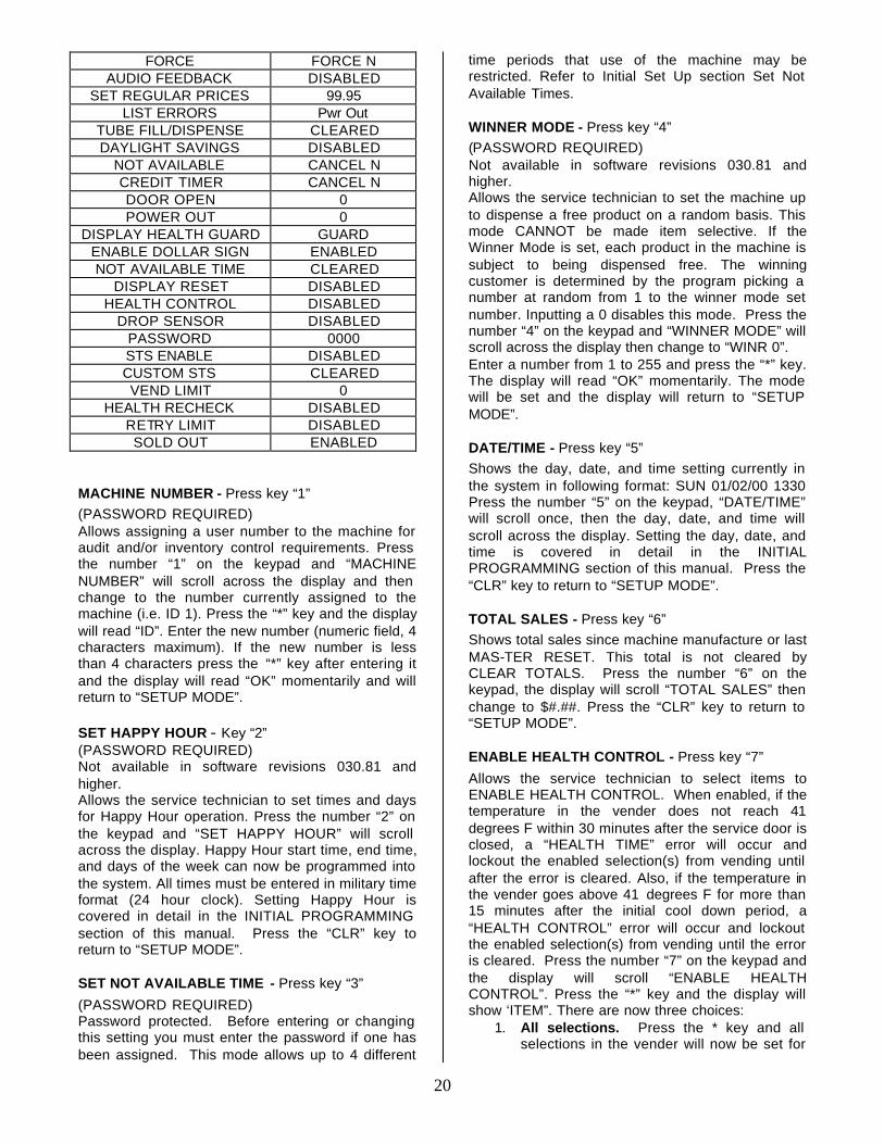
INITIAL PROGRAMMING DATE/TIME Proper setting of items such as Happy Hour and Not Available Times, as well as obtaining information regarding Door Openings, Power Outages, etc. depend on a correct DATE/TIME setting. This setting, while set at the factory, should be checked and changed if necessary. Enter “SETUP MODE” by opening the service door and pressing the Service Button 3 times. Press the number 5 key; the day, date, and time will scroll across the display in the following format: SUN 09/08/02 1330. To change press the “*” key and the display will read “SAT”. Use the “A” key to scroll through the days. When the desired day is displayed, press the “*” key. The display will read “MONTH”. Enter the 2 digits for the month and press the “*” key. The display will read “DAY”. Enter the date (2 digits) and press the “*” key. The display will read “YEAR”. Enter the year (last 2 digits) and press the “*” key. The display will read “HOUR”. Enter the hour (00 – 23) and press the “*” key. The display will read “MIN”. Enter the minutes (00 – 59) and press the “*” key. The date/time is now set and the display will return to “SETUP MODE”. REGULAR PRICES Allows the setting of regular prices for an individual item, a complete tray, or the entire machine. Factory setting is $99.95. Press the number “7” on the keypad and the display will scroll “SET REGULAR PRICES”. Press the “*” key and “$00.00” will be displayed. Prices are entered using the numbers on the keypad and will shift in from the right as numbers are pressed. Once the desired price is showing on the display, use one or all of the options listed below for setting the price to the desired selection:
1. All selections. Press the * key after entering desired price and all selections in the vender will now be set
2. One tray. Pressing the letter of the shelf followed by the * key will price that shelf to a single price. For example, to price the A shelf for $1.25, first dial in the price then choose A followed by *.
3. Single selection. Press the desired selection number or numbers corresponding to the selections that require changing.
Priority will be given to the higher ranked method. For example, If one price on the A tray was set to $1.50 using option 3 above and you wish to change the remaining selections on that tray using option 2, the pricing for the entire tray would take precedence. Conversely, if the price was set using option 2 first followed by the single selection using option 3, the pricing for the remainder of the shelf would remain
and the new price for the single selection would change to the new value. Press the “CLR” key to return to “SERVICE MODE”. POINTS TO REMEMBER:
• Prices entered must not exceed the “MAX CREDIT” set in the system’s program.
• DO NOT press the “*” key when setting prices for individual selections.
HAPPY HOUR TIMES (not available 030.81 & higher) Password protected. Before entering or changing this setting you must enter the password. To set Happy Hour Times enter the “SETUP MODE” by opening the service door and pressing the Service Button 3 times. Press the number 2 key; the display will scroll “SET HAPPY HOUR”. Press the “*” key and the display will show ”PW”. Enter the password and the display will flash “OK”. Then “HH START TIME 00 00” will scroll across display. POINTS TO REMEMBER:
• Before setting Happy Hour times and days, it is recommended you check the DATE/TIME settings.
• All times entered must be in 24 hour format.
HAPPY HOUR PRICES (not available 030.81 & higher) To set Happy Hour Prices enter the “SERVICE MODE” by opening the service door and pressing the Service Button once. Press the number 8 key; the display will scroll “SET HAPPY HOUR PRICES”. Then “$0.00” will be displayed. As the prices are entered the numbers will shift in from the right on the display. When the desired price is displayed it may be assigned to an individual selection, an entire tray (shelf), or to all selections in the machine. When setting prices for individual selections DO NOT press the “*” key. The “*” key is only used to assign a price to an entire tray or to all selections in the machine. When setting one price for an entire tray the “*” key is pressed after designating the tray (display reads $1.00 A), when the “*” key is pressed the display will read “$1.00 A” momentarily, then will return to just the price. When setting one price for an entire machine the “*” key is pressed after entering the price (display reads $1.00), when the “*” key is pressed the display will read “$1.00 **” momentarily, then will return to just the price. When setting prices for individual selections the tray and column (A1) is entered following the price. As soon as the column number is pressed, the price and selection will be displayed momentarily (“$1.00”), then the display will return to just the price. Always check the setting for “MAX CREDIT” before setting prices (not applicable to International machines). POINTS TO REMEMBER:
• Prices entered must not exceed the “MAX CREDIT” set in the system’s program.
12
• DO NOT press the “*” key when setting prices for individual selections.
SET NOT AVAILABLE TIMES Password protected. Before entering or changing this setting you must enter the password if one has been assigned. This mode allows up to 4 different time periods that use of the machine may be restricted. To set Not Available Times enter the “SETUP MODE” by opening the service door and pressing the Service Button 3 times. Press the number 3 key; the display will scroll “SET NOT AVAILABLE TIME”. Press the “*” key and the display will show ”SHUTDOWN”. Press the “A” key and the display will show “BLOCK 1” which allows selection set up. Press the “A” Key to scroll through the 4 different time periods (Block 1, 2, 3, 4) that operation of the machine will be restricted. Press the “*” key and the controller will begin displaying selections currently belonging to block until all have been displayed or the “*” key is pressed and display will show “END LIST” then “ITEM”. There are now three (3) choices:
1) ALL SELECTIONS. Press the “*” key and all selections in the vender will be set for not available.
2) ONE TRAY. Pressing the letter of the shelf (tray) followed by the “*” key will set control for all selections on that shelf.
3) SINGLE SELECTION. Press the desired selection number or numbers corresponding to the selections that require the set not available times.
Press the key buttons again and the display will flash “DISABLED” and return to “ITEM”. Priority will be given to the higher ranked method If one selection on the A tray was set to “ENABLE” using option 3 above and you wish to change the remaining selections on that tray using option 2, the Setting for the entire tray would take precedence. Conversely, if the tray was set using option 2 first followed by the single selection using option 3, the setting for the remainder of the shelf would remain and the new set not available setting would take affect. If “DISABLED” the selection will be blocked during the scheduled time period. Press the “CLR” key will exit the selection setup & start the schedule setup. “START TIME” will scroll on display once and change to “HOUR 00”. Enter the hour (00 – 23) and press the “*” key. The display will read “MIN 00”. Enter the minutes (00 – 59) and press the “*” key. “END TIME” will scroll on display once and change to “HOUR 00”. Enter the hour (00 – 23) and press the “*” key. The display will read “MIN 00”. Enter the minutes (00 – 59) and press the “*” key. “SUN N” (day) will show on the display. Press the “A” Key to toggle to “SUN Y”. To change to the next day press the “*” key and the display will read “MON N”. Use the “A” key to scroll through the days. When the desired day is displayed, press the “*” key to scroll to the next day. Press the “CLR” key to move to “BLOCK 2”.
POINTS TO REMEMBER: • Before setting Not Available times and days, it
is recommended you check the DATE/TIME settings.
• All times entered must be in 24 hour format.
13
SERVICE MODE MENU ITEMS
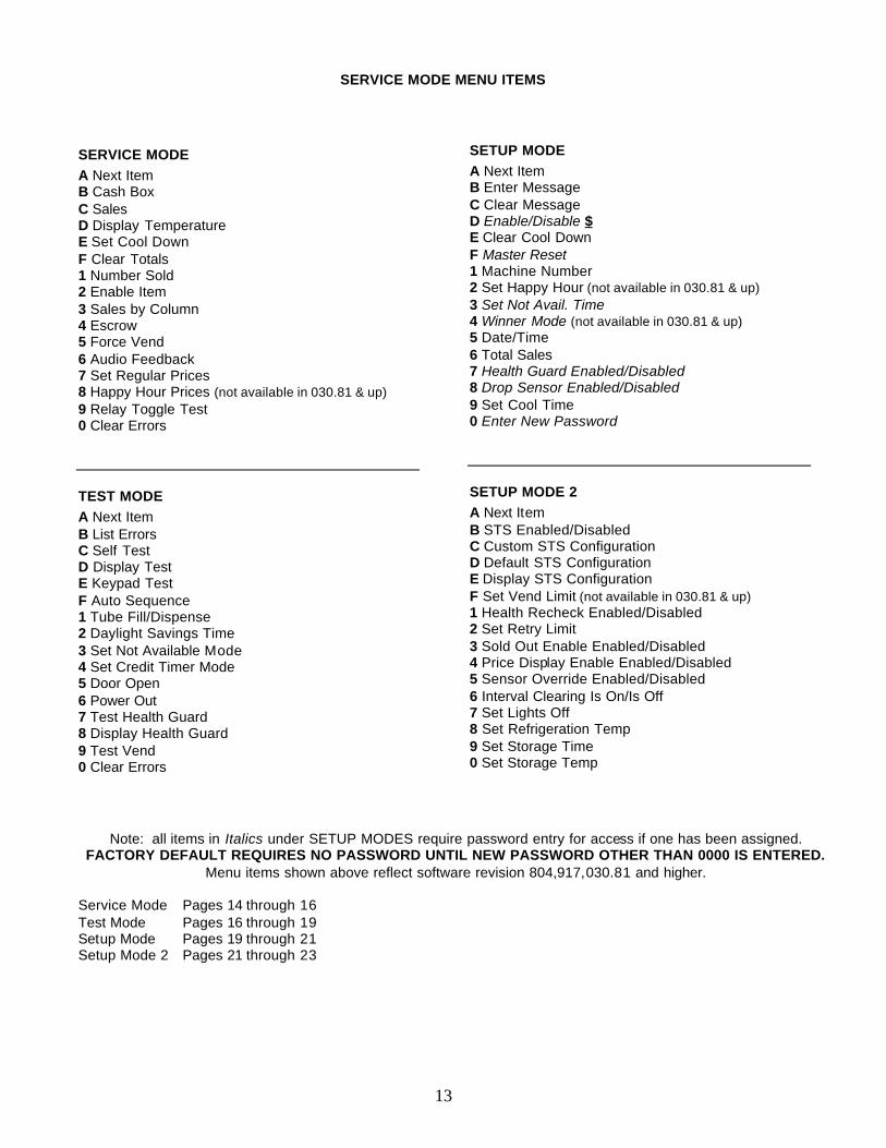
SERVICE MODE A Next Item B Cash Box C Sales D Display Temperature E Set Cool Down F Clear Totals 1 Number Sold 2 Enable Item 3 Sales by Column 4 Escrow 5 Force Vend 6 Audio Feedback 7 Set Regular Prices 8 Happy Hour Prices (not available in 030.81 & up) 9 Relay Toggle Test 0 Clear Errors
TEST MODE A Next Item B List Errors C Self Test D Display Test E Keypad Test F Auto Sequence 1 Tube Fill/Dispense 2 Daylight Savings Time 3 Set Not Available Mode 4 Set Credit Timer Mode 5 Door Open 6 Power Out 7 Test Health Guard 8 Display Health Guard 9 Test Vend 0 Clear Errors
SETUP MODE A Next Item B Enter Message C Clear Message D Enable/Disable $ E Clear Cool Down F Master Reset 1 Machine Number 2 Set Happy Hour (not available in 030.81 & up) 3 Set Not Avail. Time 4 Winner Mode (not available in 030.81 & up) 5 Date/Time 6 Total Sales 7 Health Guard Enabled/Disabled 8 Drop Sensor Enabled/Disabled 9 Set Cool Time 0 Enter New Password
SETUP MODE 2 A Next Item B STS Enabled/Disabled C Custom STS Configuration D Default STS Configuration E Display STS Configuration F Set Vend Limit (not available in 030.81 & up) 1 Health Recheck Enabled/Disabled 2 Set Retry Limit 3 Sold Out Enable Enabled/Disabled 4 Price Display Enable Enabled/Disabled 5 Sensor Override Enabled/Disabled 6 Interval Clearing Is On/Is Off 7 Set Lights Off 8 Set Refrigeration Temp 9 Set Storage Time 0 Set Storage Temp
Note: all items in Italics under SETUP MODES require password entry for access if one has been assigned.
FACTORY DEFAULT REQUIRES NO PASSWORD UNTIL NEW PASSWORD OTHER THAN 0000 IS ENTERED. Menu items shown above reflect software revision 804,917,030.81 and higher.
Service Mode Pages 14 through 16 Test Mode Pages 16 through 19 Setup Mode Pages 19 through 21 Setup Mode 2 Pages 21 through 23
14
SERVICE MODE MENU ITEMS
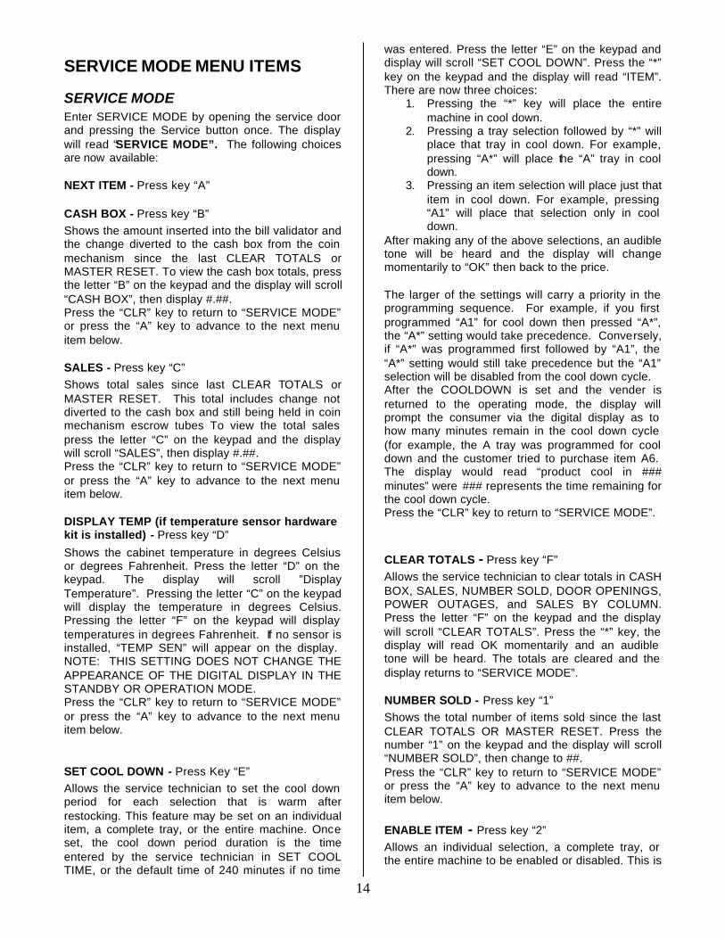
SERVICE MODE Enter SERVICE MODE by opening the service door and pressing the Service button once. The display will read “SERVICE MODE”. The following choices are now available:
NEXT ITEM - Press key “A”
CASH BOX - Press key “B” Shows the amount inserted into the bill validator and the change diverted to the cash box from the coin mechanism since the last CLEAR TOTALS or MASTER RESET. To view the cash box totals, press the letter “B” on the keypad and the display will scroll “CASH BOX”, then display #.##. Press the “CLR” key to return to “SERVICE MODE” or press the “A” key to advance to the next menu item below.
SALES - Press key “C” Shows total sales since last CLEAR TOTALS or MASTER RESET. This total includes change not diverted to the cash box and still being held in coin mechanism escrow tubes To view the total sales press the letter “C” on the keypad and the display will scroll “SALES”, then display #.##. Press the “CLR” key to return to “SERVICE MODE” or press the “A” key to advance to the next menu item below.
DISPLAY TEMP (if temperature sensor hardware kit is installed) - Press key “D”
Shows the cabinet temperature in degrees Celsius or degrees Fahrenheit. Press the letter “D” on the keypad. The display will scroll ”Display Temperature”. Pressing the letter “C” on the keypad will display the temperature in degrees Celsius. Pressing the letter “F” on the keypad will display temperatures in degrees Fahrenheit. If no sensor is installed, “TEMP SEN” will appear on the display. NOTE: THIS SETTING DOES NOT CHANGE THE APPEARANCE OF THE DIGITAL DISPLAY IN THE STANDBY OR OPERATION MODE. Press the “CLR” key to return to “SERVICE MODE” or press the “A” key to advance to the next menu item below.
SET COOL DOWN - Press Key “E” Allows the service technician to set the cool down period for each selection that is warm after restocking. This feature may be set on an individual item, a complete tray, or the entire machine. Once set, the cool down period duration is the time entered by the service technician in SET COOL TIME, or the default time of 240 minutes if no time
was entered. Press the letter “E” on the keypad and display will scroll “SET COOL DOWN”. Press the “*” key on the keypad and the display will read “ITEM”. There are now three choices:
1. Pressing the “*” key will place the entire machine in cool down.
2. Pressing a tray selection followed by “*” will place that tray in cool down. For example, pressing “A*” will place the “A” tray in cool down.
3. Pressing an item selection will place just that item in cool down. For example, pressing “A1” will place that selection only in cool down.
After making any of the above selections, an audible tone will be heard and the display will change momentarily to “OK” then back to the price. The larger of the settings will carry a priority in the programming sequence. For example, if you first programmed “A1” for cool down then pressed “A*”, the “A*” setting would take precedence. Conversely, if “A*” was programmed first followed by “A1”, the “A*” setting would still take precedence but the “A1” selection will be disabled from the cool down cycle. After the COOLDOWN is set and the vender is returned to the operating mode, the display will prompt the consumer via the digital display as to how many minutes remain in the cool down cycle (for example, the A tray was programmed for cool down and the customer tried to purchase item A6. The display would read “product cool in ### minutes” were ### represents the time remaining for the cool down cycle. Press the “CLR” key to return to “SERVICE MODE”.
CLEAR TOTALS - Press key “F” Allows the service technician to clear totals in CASH BOX, SALES, NUMBER SOLD, DOOR OPENINGS, POWER OUTAGES, and SALES BY COLUMN. Press the letter “F” on the keypad and the display will scroll “CLEAR TOTALS”. Press the “*” key, the display will read OK momentarily and an audible tone will be heard. The totals are cleared and the display returns to “SERVICE MODE”.
NUMBER SOLD - Press key “1” Shows the total number of items sold since the last CLEAR TOTALS OR MASTER RESET. Press the number “1” on the keypad and the display will scroll “NUMBER SOLD”, then change to ##. Press the “CLR” key to return to “SERVICE MODE” or press the “A” key to advance to the next menu item below.
ENABLE ITEM - Press key “2” Allows an individual selection, a complete tray, or the entire machine to be enabled or disabled. This is
15
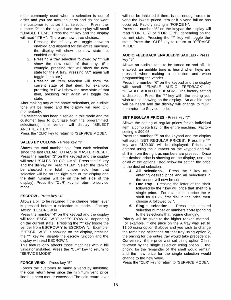
most commonly used when a selection is out of order and you are awaiting parts and do not want the customer to utilize that selection. Press the number “2” on the keypad and the display will scroll “ENABLE ITEM”. Press the “*” key and the display will read “ITEM”. There are now three choices:
1. Pressing the “*” key will toggle between enabled and disabled for the entire machine, the display will show the new state i.e. enabled or disabled.
2. Pressing a tray selection followed by “*” will show the new state of that tray. (For example, pressing “A*” will show the new state for the A tray. Pressing “A*” again will toggle the state.)
3. Pressing an item selection will show the current state of that item; for example, pressing “A1” will show the new state of that item, pressing “A1” again will toggle the state.
After making any of the above selections, an audible tone will be heard and the display will read OK momentarily. If a selection has been disabled in this mode and the customer tries to purchase from the programmed selection(s), the vender will display “SELECT ANOTHER ITEM”. Press the “CLR” key to return to “SERVICE MODE”.
SALES BY COLUMN - Press key “3”
Shows the total number sold from each selection since the last CLEAR TOTALS or MASTER RESET. Press the number “3” on the keypad and the display will scroll “SALES BY COLUMN”. Press the “*” key and the display will read “ITEM”. Select the item to be checked (the total number sold from that selection will be on the right side of the display and the item number will be on the left side of the display). Press the “CLR” key to return to service mode.
ESCROW - Press key “4” Allows a bill to be returned if the change return lever is pressed before a selection is made. Factory setting is ESCROW N. Press the number “4” on the keypad and the display will read “ESCROW Y” or “ESCROW N”, depending on the current state. Pressing the “*” key toggle the vender from ESCROW Y to ESCROW N. Example: If “ESCROW Y” is showing on the display, pressing the “*” key will disable the escrow function and the display will read ESCROW N. This feature only affects those machines with a bill validator installed. Press the “CLR” key to return to “SERVICE MODE”.
FORCE VEND - Press key “5” Forces the customer to make a vend by inhibiting the coin return lever once the minimum vend price line has been met or exceeded The coin return lever
will not be inhibited if there is not enough credit to vend the lowest priced item or if a vend failure has occurred. Factory setting is “FORCE N”. Press the number “5” on the keypad the display will read “FORCE Y” or “FORCE N”, depending on the current state. Pressing the “*” key will toggle the state. Press the “CLR” key to return to “SERVICE MODE”.
AUDIO FEEDBACK ENABLED/DISABLED - Press key “6” Allows an audible tone to be turned on and off. If enabled, an audible tone is heard when keys are pressed when making a selection and when programming the vender. Press the number “6” on the keypad and the display will scroll “ENABLE AUDIO FEEDBACK” or “DISABLE AUDIO FEEDBACK”. The factory setting is disabled. Press the “*” key with the setting you wish to use showing on the display. An audible tone will be heard and the display will change to “OK”, then return to Service mode.
SET REGULAR PRICES - Press key “7” Allows the setting of regular prices for an individual item, a complete tray, or the entire machine. Factory setting is $99.95. Press the number “7” on the keypad and the display will scroll “SET REGULAR PRICES”. Press the “*” key and “$00.00” will be displayed. Prices are entered using the numbers on the keypad and will shift in from the right as numbers are pressed. Once the desired price is showing on the display, use one or all of the options listed below for setting the price to the desired selection:
4. All selections. Press the * key after entering desired price and all selections in the vender will now be set
5. One tray. Pressing the letter of the shelf followed by the * key will price that shelf to a single price. For example, to price the A shelf for $1.25, first dial in the price then choose A followed by *.
6. Single selection. Press the desired selection number or numbers corresponding to the selections that require changing.
Priority will be given to the higher ranked method. For example, If one price on the A tray was set to $1.50 using option 3 above and you wish to change the remaining selections on that tray using option 2, the pricing for the entire tray would take precedence. Conversely, if the price was set using option 2 first followed by the single selection using option 3, the pricing for the remainder of the shelf would remain and the new price for the single selection would change to the new value. Press the “CLR” key to return to “SERVICE MODE”.
16
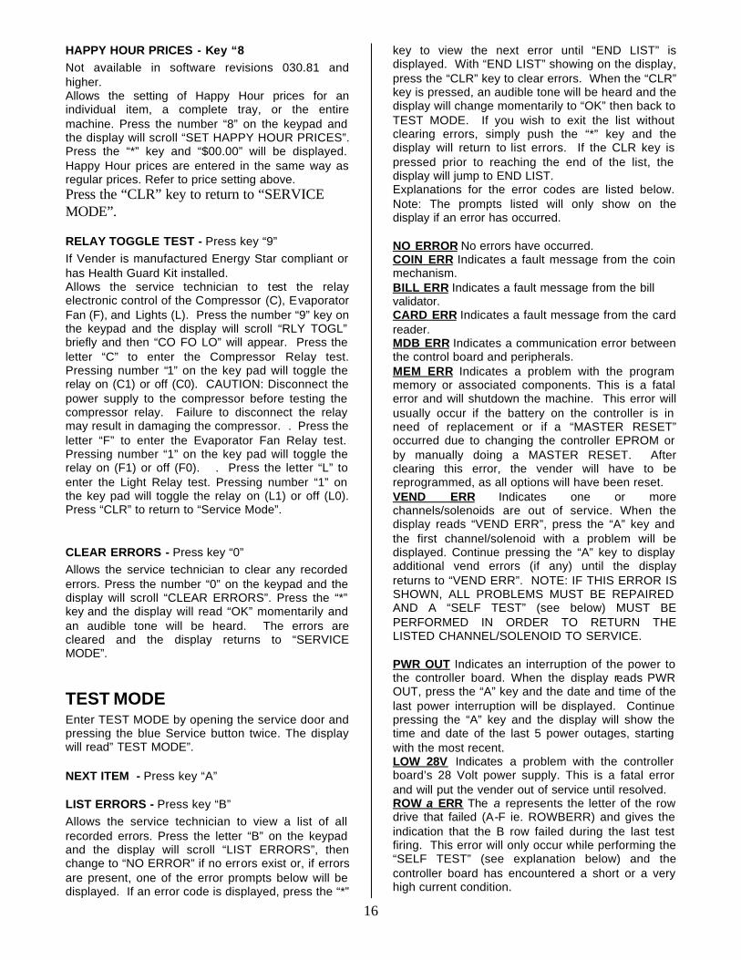
HAPPY HOUR PRICES - Key “8 Not available in software revisions 030.81 and higher. Allows the setting of Happy Hour prices for an individual item, a complete tray, or the entire machine. Press the number “8” on the keypad and the display will scroll “SET HAPPY HOUR PRICES”. Press the “*” key and “$00.00” will be displayed. Happy Hour prices are entered in the same way as regular prices. Refer to price setting above. Press the “CLR” key to return to “SERVICE MODE”.
RELAY TOGGLE TEST - Press key “9” If Vender is manufactured Energy Star compliant or has Health Guard Kit installed. Allows the service technician to test the relay electronic control of the Compressor (C), Evaporator Fan (F), and Lights (L). Press the number “9” key on the keypad and the display will scroll “RLY TOGL” briefly and then “CO FO LO” will appear. Press the letter “C” to enter the Compressor Relay test. Pressing number “1” on the key pad will toggle the relay on (C1) or off (C0). CAUTION: Disconnect the power supply to the compressor before testing the compressor relay. Failure to disconnect the relay may result in damaging the compressor. . Press the letter “F” to enter the Evaporator Fan Relay test. Pressing number “1” on the key pad will toggle the relay on (F1) or off (F0). . Press the letter “L” to enter the Light Relay test. Pressing number “1” on the key pad will toggle the relay on (L1) or off (L0). Press “CLR” to return to “Service Mode”.
CLEAR ERRORS - Press key “0” Allows the service technician to clear any recorded errors. Press the number “0” on the keypad and the display will scroll “CLEAR ERRORS”. Press the “*” key and the display will read “OK” momentarily and an audible tone will be heard. The errors are cleared and the display returns to “SERVICE MODE”.
TEST MODE Enter TEST MODE by opening the service door and pressing the blue Service button twice. The display will read” TEST MODE”.
NEXT ITEM - Press key “A”
LIST ERRORS - Press key “B” Allows the service technician to view a list of all recorded errors. Press the letter “B” on the keypad and the display will scroll “LIST ERRORS”, then change to “NO ERROR” if no errors exist or, if errors are present, one of the error prompts below will be displayed. If an error code is displayed, press the “*”
key to view the next error until “END LIST” is displayed. With “END LIST” showing on the display, press the “CLR” key to clear errors. When the “CLR” key is pressed, an audible tone will be heard and the display will change momentarily to “OK” then back to TEST MODE. If you wish to exit the list without clearing errors, simply push the “*” key and the display will return to list errors. If the CLR key is pressed prior to reaching the end of the list, the display will jump to END LIST. Explanations for the error codes are listed below. Note: The prompts listed will only show on the display if an error has occurred. NO ERROR No errors have occurred. COIN ERR Indicates a fault message from the coin mechanism. BILL ERR Indicates a fault message from the bill validator. CARD ERR Indicates a fault message from the card reader. MDB ERR Indicates a communication error between the control board and peripherals. MEM ERR Indicates a problem with the program memory or associated components. This is a fatal error and will shutdown the machine. This error will usually occur if the battery on the controller is in need of replacement or if a “MASTER RESET” occurred due to changing the controller EPROM or by manually doing a MASTER RESET. After clearing this error, the vender will have to be reprogrammed, as all options will have been reset. VEND ERR Indicates one or more channels/solenoids are out of service. When the display reads “VEND ERR”, press the “A” key and the first channel/solenoid with a problem will be displayed. Continue pressing the “A” key to display additional vend errors (if any) until the display returns to “VEND ERR”. NOTE: IF THIS ERROR IS SHOWN, ALL PROBLEMS MUST BE REPAIRED AND A “SELF TEST” (see below) MUST BE PERFORMED IN ORDER TO RETURN THE LISTED CHANNEL/SOLENOID TO SERVICE. PWR OUT Indicates an interruption of the power to the controller board. When the display reads PWR OUT, press the “A” key and the date and time of the last power interruption will be displayed. Continue pressing the “A” key and the display will show the time and date of the last 5 power outages, starting with the most recent. LOW 28V Indicates a problem with the controller board’s 28 Volt power supply. This is a fatal error and will put the vender out of service until resolved. ROW a ERR The a represents the letter of the row drive that failed (A-F ie. ROWBERR) and gives the indication that the B row failed during the last test firing. This error will only occur while performing the “SELF TEST” (see explanation below) and the controller board has encountered a short or a very high current condition.
17
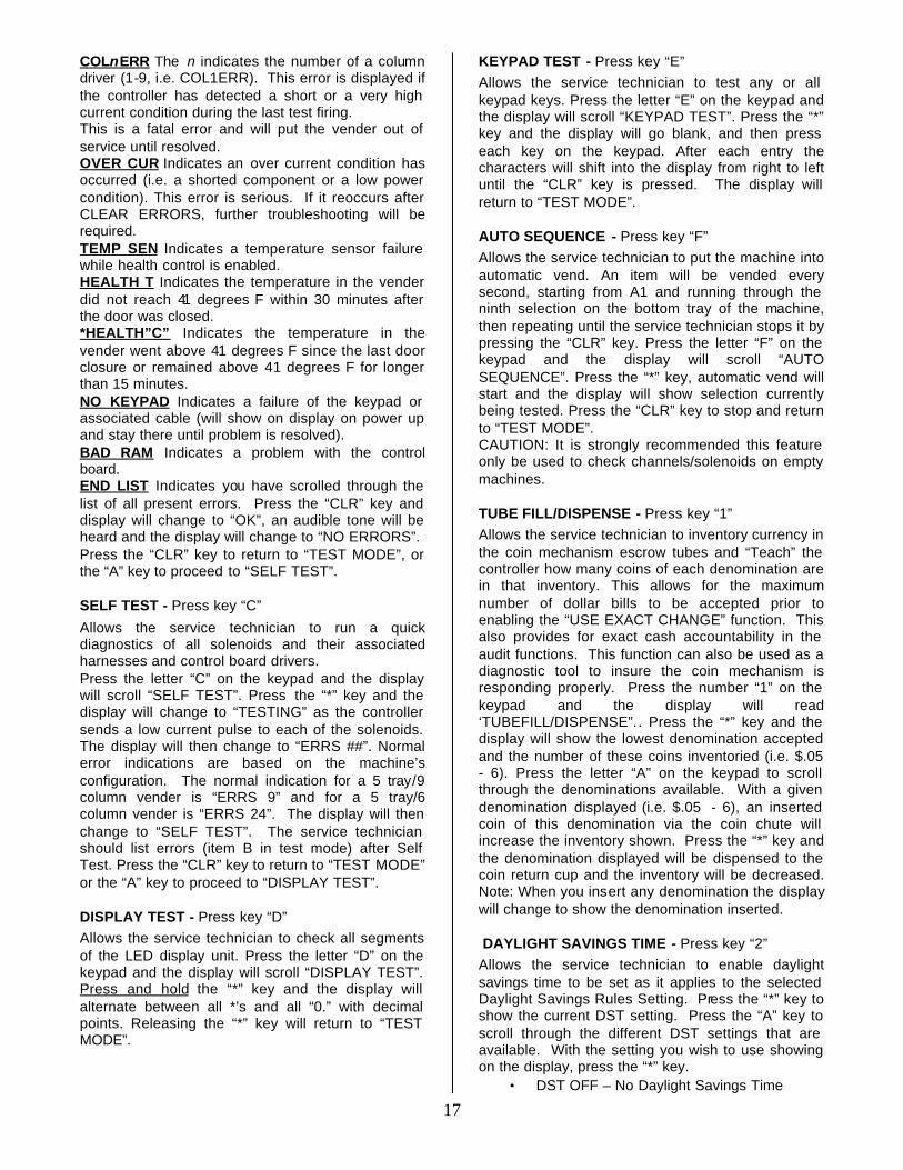
COLnERR The n indicates the number of a column driver (1-9, i.e. COL1ERR). This error is displayed if the controller has detected a short or a very high current condition during the last test firing. This is a fatal error and will put the vender out of service until resolved. OVER CUR Indicates an over current condition has occurred (i.e. a shorted component or a low power condition). This error is serious. If it reoccurs after CLEAR ERRORS, further troubleshooting will be required. TEMP SEN Indicates a temperature sensor failure while health control is enabled. HEALTH T Indicates the temperature in the vender did not reach 41 degrees F within 30 minutes after the door was closed. *HEALTH”C” Indicates the temperature in the vender went above 41 degrees F since the last door closure or remained above 41 degrees F for longer than 15 minutes. NO KEYPAD Indicates a failure of the keypad or associated cable (will show on display on power up and stay there until problem is resolved). BAD RAM Indicates a problem with the control board. END LIST Indicates you have scrolled through the list of all present errors. Press the “CLR” key and display will change to “OK”, an audible tone will be heard and the display will change to “NO ERRORS”. Press the “CLR” key to return to “TEST MODE”, or the “A” key to proceed to “SELF TEST”.
SELF TEST - Press key “C”
Allows the service technician to run a quick diagnostics of all solenoids and their associated harnesses and control board drivers. Press the letter “C” on the keypad and the display will scroll “SELF TEST”. Press the “*” key and the display will change to “TESTING” as the controller sends a low current pulse to each of the solenoids. The display will then change to “ERRS ##”. Normal error indications are based on the machine’s configuration. The normal indication for a 5 tray/9 column vender is “ERRS 9” and for a 5 tray/6 column vender is “ERRS 24”. The display will then change to “SELF TEST”. The service technician should list errors (item B in test mode) after Self Test. Press the “CLR” key to return to “TEST MODE” or the “A” key to proceed to “DISPLAY TEST”.
DISPLAY TEST - Press key “D” Allows the service technician to check all segments of the LED display unit. Press the letter “D” on the keypad and the display will scroll “DISPLAY TEST”. Press and hold the “*” key and the display will alternate between all *’s and all “0.” with decimal points. Releasing the “*” key will return to “TEST MODE”.
KEYPAD TEST - Press key “E” Allows the service technician to test any or all keypad keys. Press the letter “E” on the keypad and the display will scroll “KEYPAD TEST”. Press the “*” key and the display will go blank, and then press each key on the keypad. After each entry the characters will shift into the display from right to left until the “CLR” key is pressed. The display will return to “TEST MODE”.
AUTO SEQUENCE - Press key “F” Allows the service technician to put the machine into automatic vend. An item will be vended every second, starting from A1 and running through the ninth selection on the bottom tray of the machine, then repeating until the service technician stops it by pressing the “CLR” key. Press the letter “F” on the keypad and the display will scroll “AUTO SEQUENCE”. Press the “*” key, automatic vend will start and the display will show selection currently being tested. Press the “CLR” key to stop and return to “TEST MODE”. CAUTION: It is strongly recommended this feature only be used to check channels/solenoids on empty machines.
TUBE FILL/DISPENSE - Press key “1” Allows the service technician to inventory currency in the coin mechanism escrow tubes and “Teach” the controller how many coins of each denomination are in that inventory. This allows for the maximum number of dollar bills to be accepted prior to enabling the “USE EXACT CHANGE” function. This also provides for exact cash accountability in the audit functions. This function can also be used as a diagnostic tool to insure the coin mechanism is responding properly. Press the number “1” on the keypad and the display will read ‘TUBEFILL/DISPENSE”.. Press the “*” key and the display will show the lowest denomination accepted and the number of these coins inventoried (i.e. $.05 - 6). Press the letter “A” on the keypad to scroll through the denominations available. With a given denomination displayed (i.e. $.05 - 6), an inserted coin of this denomination via the coin chute will increase the inventory shown. Press the “*” key and the denomination displayed will be dispensed to the coin return cup and the inventory will be decreased. Note: When you insert any denomination the display will change to show the denomination inserted.
DAYLIGHT SAVINGS TIME - Press key “2” Allows the service technician to enable daylight savings time to be set as it applies to the selected Daylight Savings Rules Setting. Press the “*” key to show the current DST setting. Press the “A” key to scroll through the different DST settings that are available. With the setting you wish to use showing on the display, press the “*” key.
• DST OFF – No Daylight Savings Time
18
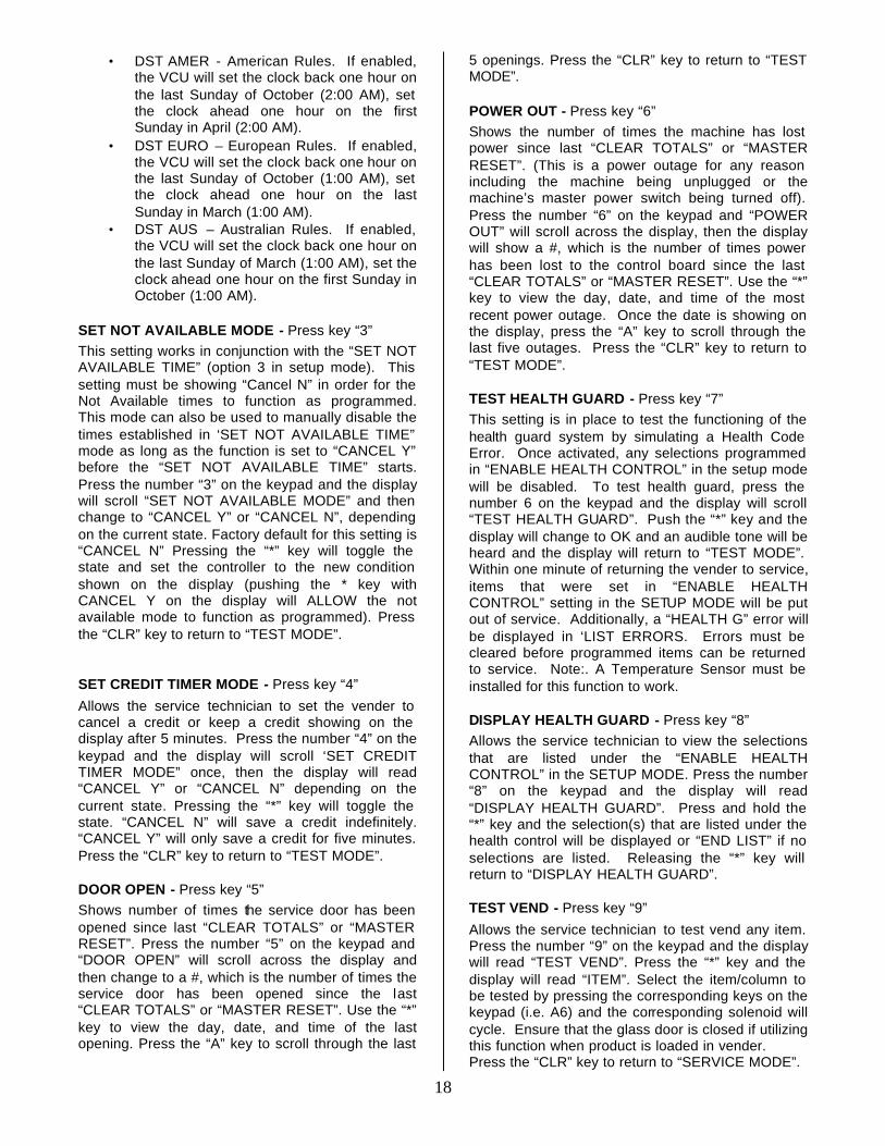
• DST AMER - American Rules. If enabled, the VCU will set the clock back one hour on the last Sunday of October (2:00 AM), set the clock ahead one hour on the first Sunday in April (2:00 AM).
• DST EURO – European Rules. If enabled, the VCU will set the clock back one hour on the last Sunday of October (1:00 AM), set the clock ahead one hour on the last Sunday in March (1:00 AM).
• DST AUS – Australian Rules. If enabled, the VCU will set the clock back one hour on the last Sunday of March (1:00 AM), set the clock ahead one hour on the first Sunday in October (1:00 AM).
SET NOT AVAILABLE MODE - Press key “3” This setting works in conjunction with the “SET NOT AVAILABLE TIME” (option 3 in setup mode). This setting must be showing “Cancel N” in order for the Not Available times to function as programmed. This mode can also be used to manually disable the times established in ‘SET NOT AVAILABLE TIME” mode as long as the function is set to “CANCEL Y” before the “SET NOT AVAILABLE TIME” starts. Press the number “3” on the keypad and the display will scroll “SET NOT AVAILABLE MODE” and then change to “CANCEL Y” or “CANCEL N”, depending on the current state. Factory default for this setting is “CANCEL N” Pressing the “*” key will toggle the state and set the controller to the new condition shown on the display (pushing the * key with CANCEL Y on the display will ALLOW the not available mode to function as programmed). Press the “CLR” key to return to “TEST MODE”.
SET CREDIT TIMER MODE - Press key “4”
Allows the service technician to set the vender to cancel a credit or keep a credit showing on the display after 5 minutes. Press the number “4” on the keypad and the display will scroll ‘SET CREDIT TIMER MODE” once, then the display will read “CANCEL Y” or “CANCEL N” depending on the current state. Pressing the “*” key will toggle the state. “CANCEL N” will save a credit indefinitely. “CANCEL Y” will only save a credit for five minutes. Press the “CLR” key to return to “TEST MODE”.
DOOR OPEN - Press key “5” Shows number of times the service door has been opened since last “CLEAR TOTALS” or “MASTER RESET”. Press the number “5” on the keypad and “DOOR OPEN” will scroll across the display and then change to a #, which is the number of times the service door has been opened since the last “CLEAR TOTALS” or “MASTER RESET”. Use the “*” key to view the day, date, and time of the last opening. Press the “A” key to scroll through the last
5 openings. Press the “CLR” key to return to “TEST MODE”.
POWER OUT - Press key “6” Shows the number of times the machine has lost power since last “CLEAR TOTALS” or “MASTER RESET”. (This is a power outage for any reason including the machine being unplugged or the machine’s master power switch being turned off). Press the number “6” on the keypad and “POWER OUT” will scroll across the display, then the display will show a #, which is the number of times power has been lost to the control board since the last “CLEAR TOTALS” or “MASTER RESET”. Use the “*” key to view the day, date, and time of the most recent power outage. Once the date is showing on the display, press the “A” key to scroll through the last five outages. Press the “CLR” key to return to “TEST MODE”.
TEST HEALTH GUARD - Press key “7” This setting is in place to test the functioning of the health guard system by simulating a Health Code Error. Once activated, any selections programmed in “ENABLE HEALTH CONTROL” in the setup mode will be disabled. To test health guard, press the number 6 on the keypad and the display will scroll “TEST HEALTH GUARD”. Push the “*” key and the display will change to OK and an audible tone will be heard and the display will return to “TEST MODE”. Within one minute of returning the vender to service, items that were set in “ENABLE HEALTH CONTROL” setting in the SETUP MODE will be put out of service. Additionally, a “HEALTH G” error will be displayed in ‘LIST ERRORS. Errors must be cleared before programmed items can be returned to service. Note:. A Temperature Sensor must be installed for this function to work.
DISPLAY HEALTH GUARD - Press key “8” Allows the service technician to view the selections that are listed under the “ENABLE HEALTH CONTROL” in the SETUP MODE. Press the number “8” on the keypad and the display will read “DISPLAY HEALTH GUARD”. Press and hold the “*” key and the selection(s) that are listed under the health control will be displayed or “END LIST” if no selections are listed. Releasing the “*” key will return to “DISPLAY HEALTH GUARD”.
TEST VEND - Press key “9”
Allows the service technician to test vend any item. Press the number “9” on the keypad and the display will read “TEST VEND”. Press the “*” key and the display will read “ITEM”. Select the item/column to be tested by pressing the corresponding keys on the keypad (i.e. A6) and the corresponding solenoid will cycle. Ensure that the glass door is closed if utilizing this function when product is loaded in vender. Press the “CLR” key to return to “SERVICE MODE”.
19
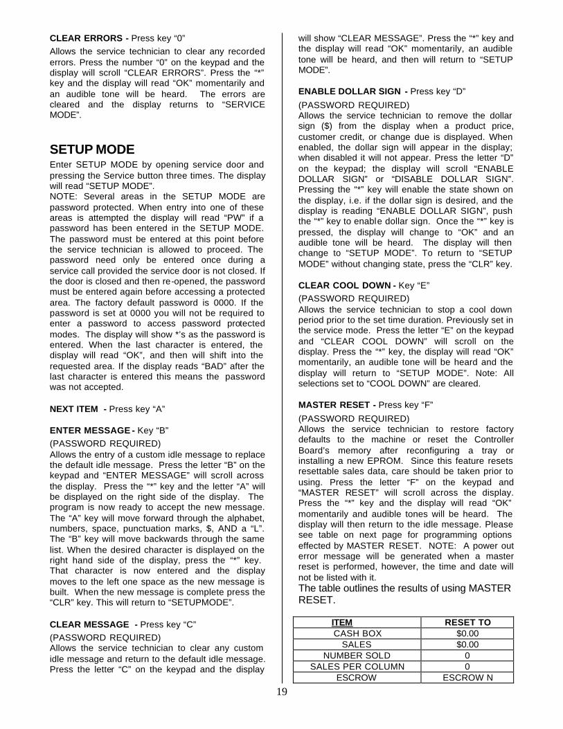
CLEAR ERRORS - Press key “0” Allows the service technician to clear any recorded errors. Press the number “0” on the keypad and the display will scroll “CLEAR ERRORS”. Press the “*” key and the display will read “OK” momentarily and an audible tone will be heard. The errors are cleared and the display returns to “SERVICE MODE”.
SETUP MODE Enter SETUP MODE by opening service door and pressing the Service button three times. The display will read “SETUP MODE”. NOTE: Several areas in the SETUP MODE are password protected. When entry into one of these areas is attempted the display will read “PW” if a password has been entered in the SETUP MODE. The password must be entered at this point before the service technician is allowed to proceed. The password need only be entered once during a service call provided the service door is not closed. If the door is closed and then re-opened, the password must be entered again before accessing a protected area. The factory default password is 0000. If the password is set at 0000 you will not be required to enter a password to access password protected modes. The display will show *’s as the password is entered. When the last character is entered, the display will read “OK”, and then will shift into the requested area. If the display reads “BAD” after the last character is entered this means the password was not accepted.
NEXT ITEM - Press key “A”
ENTER MESSAGE - Key “B” (PASSWORD REQUIRED) Allows the entry of a custom idle message to replace the default idle message. Press the letter “B” on the keypad and “ENTER MESSAGE” will scroll across the display. Press the “*” key and the letter “A” will be displayed on the right side of the display. The program is now ready to accept the new message. The “A” key will move forward through the alphabet, numbers, space, punctuation marks, $, AND a “L”. The “B” key will move backwards through the same list. When the desired character is displayed on the right hand side of the display, press the “*” key. That character is now entered and the display moves to the left one space as the new message is built. When the new message is complete press the “CLR” key. This will return to “SETUPMODE”.
CLEAR MESSAGE - Press key “C” (PASSWORD REQUIRED) Allows the service technician to clear any custom idle message and return to the default idle message. Press the letter “C” on the keypad and the display
will show “CLEAR MESSAGE”. Press the “*” key and the display will read “OK” momentarily, an audible tone will be heard, and then will return to “SETUP MODE”.
ENABLE DOLLAR SIGN - Press key “D”
(PASSWORD REQUIRED) Allows the service technician to remove the dollar sign ($) from the display when a product price, customer credit, or change due is displayed. When enabled, the dollar sign will appear in the display; when disabled it will not appear. Press the letter “D” on the keypad; the display will scroll “ENABLE DOLLAR SIGN” or “DISABLE DOLLAR SIGN”. Pressing the “*” key will enable the state shown on the display, i.e. if the dollar sign is desired, and the display is reading “ENABLE DOLLAR SIGN”, push the “*” key to enable dollar sign. Once the “*” key is pressed, the display will change to “OK” and an audible tone will be heard. The display will then change to “SETUP MODE”. To return to “SETUP MODE” without changing state, press the “CLR” key.
CLEAR COOL DOWN - Key “E” (PASSWORD REQUIRED) Allows the service technician to stop a cool down period prior to the set time duration. Previously set in the service mode. Press the letter “E” on the keypad and “CLEAR COOL DOWN” will scroll on the display. Press the “*” key, the display will read “OK” momentarily, an audible tone will be heard and the display will return to “SETUP MODE”. Note: All selections set to “COOL DOWN” are cleared.
MASTER RESET - Press key “F”
(PASSWORD REQUIRED) Allows the service technician to restore factory defaults to the machine or reset the Controller Board’s memory after reconfiguring a tray or installing a new EPROM. Since this feature resets resettable sales data, care should be taken prior to using. Press the letter “F” on the keypad and “MASTER RESET” will scroll across the display. Press the “*” key and the display will read “OK” momentarily and audible tones will be heard. The display will then return to the idle message. Please see table on next page for programming options effected by MASTER RESET. NOTE: A power out error message will be generated when a master reset is performed, however, the time and date will not be listed with it. The table outlines the results of using MASTER RESET.
ITEM RESET TO CASH BOX $0.00
SALES $0.00 NUMBER SOLD 0
SALES PER COLUMN 0 ESCROW ESCROW N
20
FORCE FORCE N AUDIO FEEDBACK DISABLED
SET REGULAR PRICES 99.95 LIST ERRORS Pwr Out
TUBE FILL/DISPENSE CLEARED DAYLIGHT SAVINGS DISABLED
NOT AVAILABLE CANCEL N CREDIT TIMER CANCEL N DOOR OPEN 0 POWER OUT 0
DISPLAY HEALTH GUARD GUARD ENABLE DOLLAR SIGN ENABLED NOT AVAILABLE TIME CLEARED
DISPLAY RESET DISABLED HEALTH CONTROL DISABLED
DROP SENSOR DISABLED PASSWORD 0000 STS ENABLE DISABLED CUSTOM STS CLEARED VEND LIMIT 0
HEALTH RECHECK DISABLED RETRY LIMIT DISABLED SOLD OUT ENABLED
MACHINE NUMBER - Press key “1” (PASSWORD REQUIRED) Allows assigning a user number to the machine for audit and/or inventory control requirements. Press the number “1” on the keypad and “MACHINE NUMBER” will scroll across the display and then change to the number currently assigned to the machine (i.e. ID 1). Press the “*” key and the display will read “ID”. Enter the new number (numeric field, 4 characters maximum). If the new number is less than 4 characters press the “*” key after entering it and the display will read “OK” momentarily and will return to “SETUP MODE”. SET HAPPY HOUR - Key “2” (PASSWORD REQUIRED) Not available in software revisions 030.81 and higher. Allows the service technician to set times and days for Happy Hour operation. Press the number “2” on the keypad and “SET HAPPY HOUR” will scroll across the display. Happy Hour start time, end time, and days of the week can now be programmed into the system. All times must be entered in military time format (24 hour clock). Setting Happy Hour is covered in detail in the INITIAL PROGRAMMING section of this manual. Press the “CLR” key to return to “SETUP MODE”.
SET NOT AVAILABLE TIME - Press key “3”
(PASSWORD REQUIRED) Password protected. Before entering or changing this setting you must enter the password if one has been assigned. This mode allows up to 4 different
time periods that use of the machine may be restricted. Refer to Initial Set Up section Set Not Available Times.
WINNER MODE - Press key “4” (PASSWORD REQUIRED) Not available in software revisions 030.81 and higher. Allows the service technician to set the machine up to dispense a free product on a random basis. This mode CANNOT be made item selective. If the Winner Mode is set, each product in the machine is subject to being dispensed free. The winning customer is determined by the program picking a number at random from 1 to the winner mode set number. Inputting a 0 disables this mode. Press the number “4” on the keypad and “WINNER MODE” will scroll across the display then change to “WINR 0”. Enter a number from 1 to 255 and press the “*” key. The display will read “OK” momentarily. The mode will be set and the display will return to “SETUP MODE”.
DATE/TIME - Press key “5” Shows the day, date, and time setting currently in the system in following format: SUN 01/02/00 1330 Press the number “5” on the keypad, “DATE/TIME” will scroll once, then the day, date, and time will scroll across the display. Setting the day, date, and time is covered in detail in the INITIAL PROGRAMMING section of this manual. Press the “CLR” key to return to “SETUP MODE”.
TOTAL SALES - Press key “6” Shows total sales since machine manufacture or last MAS-TER RESET. This total is not cleared by CLEAR TOTALS. Press the number “6” on the keypad, the display will scroll “TOTAL SALES” then change to $#.##. Press the “CLR” key to return to “SETUP MODE”.
ENABLE HEALTH CONTROL - Press key “7”
Allows the service technician to select items to ENABLE HEALTH CONTROL. When enabled, if the temperature in the vender does not reach 41 degrees F within 30 minutes after the service door is closed, a “HEALTH TIME” error will occur and lockout the enabled selection(s) from vending until after the error is cleared. Also, if the temperature in the vender goes above 41 degrees F for more than 15 minutes after the initial cool down period, a “HEALTH CONTROL” error will occur and lockout the enabled selection(s) from vending until the error is cleared. Press the number “7” on the keypad and the display will scroll “ENABLE HEALTH CONTROL”. Press the “*” key and the display will show ‘ITEM”. There are now three choices:
1. All selections. Press the * key and all selections in the vender will now be set for
21
health control. The display will change to “ENABLED” then back to “ITEM”.
2. One tray. Pressing the letter of the shelf followed by the * key will set control for all selections on that shelf. For example, to control the A shelf push key “A” followed by “*” key. The display will change to “ENABLED” then back to “ITEM”.
3. Single selection. Press the desired selection number or numbers corresponding to the selections that require the health control function. After each selection is made the display will change to “ENABLED” then back to “ITEM”.
Press the keypad buttons again and the display will flash “DISABLED” and return to “ITEM”. Priority will be given to the higher ranked method If one selection on the A tray was set to ENABLE using option 3 above and you wish to change the remaining selections on that tray using option 2, the Setting for the entire tray would take precedence. Conversely, if the tray was set using option 2 first followed by the single selection using option 3, the setting for the remainder of the shelf would remain and the new price for the single selection would change to the new value. Press “CLR” to return to “SETUP MODE”.
DROP SENSOR ENABLED/DISABLED - Press key “8” (PASSWORD REQUIRED) Allows Enabling or Disabling of drop sensor Credit Guard function. When enabled, the customer will retain credit for the amount deposited if a product does not pass through the sensor beam in the recovery unit. This state will allow three attempts to vend a product before credit is lost. Both states will prevent a vend if a product is in the recovery unit. Press the number “8” on the keypad and “ENABLE DROP SENSOR” or “DISABLE DROP SENSOR” will scroll across the display. Pressing the “*” key will switch the state. Note: When the display shows enabled, the state is actually disabled. Press the “CLR” key to return to “SETUP MODE”.
SET COOL TIME - Key “9” Allows the service technician to vary the time duration of the cool down period from 0 to 255 minutes. If no time is entered here, and the SET COOL DOWN feature is started, the time duration of the cool down period will be 240 minutes (4 hours). To set the cool down time press the letter “D” on the keypad and the display will scroll “SET COOL TIME”, and then change to “COOL 240”. Use the keypad to enter the duration of the cool down period that you wish to use. Press the “*” key to enter your preferred time into memory. The display will read “OK” momentarily and return to “SETUP MODE”.
ENTER NEW PASSWORD - Press key “0” (PASSWORD REQUIRED) Allows the service technician to enter a personalized password. IF YOU DECIDE TO CHANGE FROM THE DEFAULT PASSWORD, PLEASE ENTER THE NEW PASSWORD SLOWLY AND CAREFULLY!!! Press the number “0” on the keypad and “ENTER PASSWORD” will scroll across the display. Press the “*” key and the display will read “PW”. Enter the password, the display will read “OK” momentarily then “NEW PW” will be displayed. Enter the new password. After the fourth character of the new Password is entered the display will read “OK” momentarily and return to “SETUP MODE”.
SETUP MODE 2 Enter SETUP MODE 2 by opening the main door and pushing the Service button four times. The display will read “SETUP MODE 2”
NEXT ITEM - Press key “A”
SPACE TO SALES ENABLE/DISABLE - Press key “B”
Allows enabling or disabling the Space-to-Sales vend mode. When Enabled, Space-to-Sales vends are performed according to the configurations defined using “DEFAULT STS CONFIG” and/or “CUSTOM STS CONFIG”. Press the Letter “B” on the keypad. The display will scroll the current state of the Space-to Sales vend mode as “STS ENABLED” OR “STS DISABLED”. There are now two choices:
1. Press the “CLR” key to leave the Space-to-Sales vend mode unchanged and return to “SETUP MODE 2”
2. Press the “*” key to toggle the state. The display will scroll a new message indicating the updated state.
CUSTOM STS CONFIG - Press key “C”
Configures the Space-to-Sales according to user input. Press the letter “C” on the keypad. The display will read “START”. There are now 3 choices:
1. Pressing the “*” key will set STS to a one to one configuration such that each selection is mapped only to it’s corresponding column. Note: This setting overrides any previously defined Space-to-Sales blocks.
2. Pressing a tray selection followed by “*” will configure an entire tray as a single Space-to-Sales block. Example is selections A1 through A9 vend from columns A1 through A9 sequentially.
3. Pressing an item selection (A1) will specify the first product of the Space-to-Sales block.
22
After the first item is programmed, the display will change to “END”. Press the item selection corresponding to the last item in the block. This option may transcend more than one shelf, i.e. A1 to B9. Important Note: Any column number ending in the number “0” (ie A0, B0, C0, D0, E0) is not included in STS blocks. Example: A1 through B6 will not include A0. Also, if you use any column “0” for the end of a STS block, it will include all shelves and columns below it as the “0” columns are tied to the F tray port on the control board. Example: STS block A1 through B0 will actually include A1 through E0, but does not include A0.
In all of the above options, after a selection is made, an audible tone will be heard and the display will change briefly to “OK” then back to “START”. Press “CLR” at any time to return to SETUP MODE 2.
DEFAULT STS CONFIG - Press key “D”
Configures the Space-to-Sales to the preset mappings. Press “D” on the keypad and the display will scroll “DEFAULT STS CONFIG”. Press the “*” key to configure Space-to-Sales in preset blocks of three (A1 – A3, A4-A6, A7-A9, B1-B3,…).
DISPLAY STS CONFIG - Press key “E” Allows verification of the Space-to-Sales settings for an individual item. Press the letter “E” on the keypad. The display will scroll “DISPLAY STS CONFIG”. Press the “*” key and the display will change to “ITEM”. Enter any selection item and the display will read “##-## ##. The first ## indicates the first column in the selection’s block. The second ## indicates the last column in the selection’s block. The last ## indicates the column that the next vend will come from in this Space-to-Sales block. For example, entering “A2” might display “A1-A3 A1, indicating that selection A2 is part of the block that spans between A1 and A3 and that A1 selection is next in line to be vended.
SET VEND LIMIT - Key “F” Not available in software revisions 030.81 and higher. If a Vend fails-either due to a vend error or no product detected in the recovery unit- and the drop sensor is enabled, the VMC will mark the column as sold out. If the Space-to-Sales is enabled, the product column will be removed form the Space-to-Sales rotation and the VMC will attempt to vend from the next column in the Space-to-Sales block. If the vender is unable to vend any products from a Space-to-Sales block, the customer’s credit will be
returned and the entire block will be marked as “SOLD OUT”. Press the “F” key on the keypad. The display will scroll “SET VEND LIMIT”. Press the “*” key while the display is scrolling, or wait until the message scrolls off. The display will read” LIMIT #”. The value # is the current vend limit which is applied to each selection. When # is 0, no vend limits are enforced. Enter the desired vend limit and press the “*” key to accept this value or press the “CLR” key to cancel changes and return to SETUP MODE 2.
HEALTH RECHECK ENABLED/DISABLED - Press key “1”
When enabled, after a “HEALTH TIME” error has occurred, the vender will recheck the cooler compartment temperature 3 times in 15-minute intervals. If the temperature drops below 41 degrees, the “HEALTH TIME” error is cleared and selections are re-enabled. If any recheck reads above a previous reading, or if the temperature is not below 41 degrees by the third recheck, the “HEALTH TIME” error will remain and selections will continue to be blocked. Press the number “1” key. The display will scroll “HEALTH RECHECK ENABLED” or “HEALTH RECHECK DISABLED”. There are now 2 choices:
1. Press the “CLR” key to leave the Health Recheck setting unchanged and return to “SETUP MODE 2”
2. Press the “*” key to toggle the state. The display will scroll a new message indicating the updated state.
This setting is inconsistent with NAMA guidelines for health-controlled venders.
SET RETRY LIMIT - Press key “2” This function provides the customer with an additional opportunity (opportunities) to make a selection after a failed vend. When a retry limit is set, credit remains on the vender and the customer may make additional selections until the retry limit is reached at which point credit is returned. Press the number “2” key. The display will scroll “SET RETRY LIMIT”. Then the display will read “LIMIT #”. The value # is the current retry limit which is used after an initial failed vend. This means that a retry limit of 3 will allow the user a total of 4 selections: the initial selection plus 3 retries. After the limit is reached, credit is returned. To change the limit #, when “LIMIT #” is displayed press the # key(s) to enter the retry limit you desire to be set.
SOLD OUT ENABLED/DISABLED - Press key “3” Controls sold out detection by the drop sensor. When enabled, a signal is sent to the VCU when the
23
drop sensor does not detect a selected item. That signal tells the VCU that the item selected is sold out and removes it from the STS block until the next time the vender is servi ced. Press the number “3” on the keypad. The display will scroll “SOLD OUT ENABLED” or “SOLD OUT DISABLED”. Press the “*” key to toggle the state to the desired setting or press “CLR” to exit without making changes and return to “SETUP MODE 2”
PRICE DISPLAY ENABLED/DISABLED - Key “4”
This setting controls whether the vender displays a price when a selection is made. Machines with a card reader capable of displaying selection prices may be configured to prevent displaying prices on two separate displays. Press the number “4” on the keypad. The display will scroll “PRICE DISPLAY ENABLED” or “PRICE DISPLAY DISABLED”. Press the “*” key to toggle the state or press the “CLR” key to exit without making changes and return to SET UP MODE 2. SENSOR OVERRIDE ENABLED/DISABLED – Press key “5” This should only be used under the direction of Dixie-Narco Technical Service. Press key 5 and the display will scroll “SENSOR OVERRIDE ENABLED or DISABLED” depending on current state. Press the “*” key to toggle the state of the setting. With the display showing the state you wish to use press the “CLR” key to exit. When enabled the controller will temporarily ignore the vend sensors that may become blocked from condensation immediately after the vender as been filled. The controller will ignore the vend sensor for up to 3 minutes from the time the service door is closed. If the sensor remains clear continuously for 30 seconds the controller will return to normal operation. During the override period, any vends performed will be treated as successful vends regardless of the Drop Sensor setting, except in the case of a solenoid error. Note that after 3 minutes, a blocked sensor will effectively prevent any new vends from being started. INTERVAL CLEARING IS ON/IS OFF – Press key “6” This function is used to indicate the state of the interval clearing setting. Press the number “6” key and “INTERVAL CLEARING IS ON or OFF” will scroll across display depending on the current
setting. When “ON”, the interval (resettable) data to automatically be cleared upon successful completion of a DEX audit. When “OFF” it allows for remote auditing devices that clear resettable data manually to be used to clear the data. Press the “*” key to accept the displayed setting, press the “CLR” key to exit the menu. SET LIGHTS OFF – Press key “7” The function is used to set the Date and Day when Lights will be turned OFF. Press the number “7” key and “SET LIGHTS OFF” will scroll across display. Press the “*” Key. “START TIME” will display, then “HOUR 00” will display. Use the Keypad enter time then press “*” key. “MIN 00” will display. Use the Keypad enter time then press “*” key. “SUN N” will display. Use the “A” key to toggle “N” for No or “Y” for Yes. Press the “*” Key, the next day will appear. Repeat for all days. Press “CLR” to exit.
SET REFRIGERATION TEMP – Press key “8” This function is used to set product Temperature. Press the number “8” key and “SET REFRIGERATION TEMP” will scroll across display then “DEG F 35” will display. Use the keypad to enter the Temperature setting in degrees F. Press the “*” key to accept. “OK” will appear briefly. Press the ”CLR” key to exit. SET STORAGE TIME – Press key “9” This function is used set the Date and Day when Storage Temperature will be ON. Press the number “9” and “SET STORAGE TEMP” will scroll across display. Press the “*” Key and “START TIME” will display, then “HOUR 00” will display. Use the Keypad to enter time then press “*” key. “MIN 00” will display. Use the Keypad enter time then press “*” key. “MIN 00” will display. Use the Keypad enter time then press “*” key. “SUN N” will display. Use the “A” key to toggle “N” for No or “Y” for Yes. Press the “*” Key, the next day will appear. Repeat for all days. Press “CLR” to exit. SET STORAGE TEMP – Press key “0” This function is used to set Storage Temperature. Press the number “0” key and “SET STORAGE TEMP” will scroll across display then “DEG F 65” will display. Use the keypad to enter the Temperature setting in degrees F. Press the “*” key to accept. “OK” will appear briefly. Press the ”CLR” key to exit.
24
The most important facets of proper care and maintenance of your machine are the electrical power supplied to it, leveling, and cleanliness of the machine.
POWER The machine must be connected to a dedicated 120 VAC, 15 Amp circuit (U.S. and Canada). Refer To the cabinet serial number plate to determine the proper voltage and frequency the machine requires.
CAUTION: REMOVE POWER TO THE AC DISTRIBUTION
BOX BEFORE CLEANING OR WHE N ANY ELECTRICAL COMPONENTS ARE
CONNECTED/DISCONNECTED FOR TESTING OR REPLACEMENT
CLEANING DO NOT USE A WATER JET OR NOZZLE TO CLEAN THE VENDER
GLASS DOOR The display glass should be cleaned inside and out with paper towels and glass or non-abrasive all-purpose cleaner. The gasket around the product door should be wiped down using warm water, any mild general purpose, non-abrasive cleaner and a soft towel. Never lubricate the gasket and always check for cracking or deformities which may cause leaks. Replace if necessary.
TRAYS / TRAY INSERTS
The trays and tray inserts should be cleaned periodically using warm water and a mild general purpose, non-abrasive cleaner. Care should be taken to ensure water does not enter the solenoids. DO NOT USE SOLVENTS OR ABRASIVE MATERIALS TO CLEAN ANY PORTION OF THE TRAY.
SLIDE/PUSHER ASSEMBLY The slide/pusher assembly should be cleaned periodically using warm water and any mild general-purpose non-abrasive cleaner. After drying, the slide assembly needs to have a coat of Armorall applied. Care should be taken to ensure liquid does not enter solenoids. DO NOT USE SOLVENTS OR ABRASIVE MATERIALS TO CLEAN ANY PORTION OF THE TRAY.
CABINET Wash the cabinet with a good detergent or soap mixed in warm water. Wax the vender often with a good grade of automobile wax. Any corrosion inside the vender should be removed with fine steel wool and the area should be painted with
white paint. Repair any scratches on painted surfaces to prevent corrosion.
RECOVERY UNIT Cleaning of the product delivery bin and condenser area requires removal of the product delivery bin. To remove:
Open the service door. Open the product door. Pull the bin straight out until clear of the machine and set aside.
When installing, make sure the recovery unit is pushed all the way back before closing the product and service doors.
DRAIN PAN, DRAIN TUBE, AND DRAN HOSE
To prevent mold and mildew growth, and to avoid personal injury or property damage, the drain pan, drain tube, and drain hose must be properly aligned and routed. Ensure nothing obstructs the drain tube or drain hose and that the hose is not bent, pinched, or twisted in such a was as to prevent the flow of condensate. Periodically inspect the drain pan, drain tube, and drain hose for alignment and the presence of dirt, debris, mold, and mildew. Clean as needed.
WARNING THE COMPRESSOR ELECTRICAL CIRCUIT IS ALWAYS LIVE WHEN THE PLUG IS CONNECTED TO AN ELECTRICAL OUTLET.
REFRIGERATION CONDENSER Clean the condenser periodically of dirt or lint build-up. Remove the build up with a brush or vacuum, or blow the dirt out of the condenser with compressed air and approved safety nozzle. Ensure nothing obstructs air intake at the bottom of the main door. Ensure nothing obstructs air exhaust at the rear of the cabinet.
COIN ACCEPTOR
Follow the Coin Acceptor Manufacturer’s instructions.
LUBRICATING THE VENDER
The vender refrigeration system does not require any field lubrication. The hermetic refrigeration system and fan motors are manufactured with lifetime lubrication.
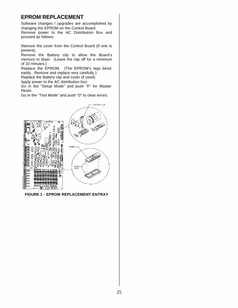
25
EPROM REPLACEMENT Software changes / upgrades are accomplished by changing the EPROM on the Control Board. Remove power to the AC Distribution Box and proceed as follows: Remove the cover from the Control Board (if one is present). Remove the Battery clip to allow the Board’s memory to drain. (Leave the clip off for a minimum of 10 minutes.) Replace the EPROM. (The EPROM’s legs bend easily. Remove and replace very carefully.) Replace the Battery clip and cover (if used). Apply power to the AC distribution box. Go in the “Setup Mode” and push “F” for Master Reset. Go in the “Test Mode” and push “0” to clear errors.
FIGURE 1 - EPROM REPLACEMENT ENTRAY
26
AC DISTRIBUTION BOX DN55##/54##/DN2145 110 VAC and 220 VAC units
Main Power Switch / Plug Interrupts hot side of incoming power to all components in machine.
15 Amp Outlet (110 VAC) Provides power to 15 Amp Outlet (220 VAC) refrigeration unit. Transformer (T1) Provides 24 Volt
and 12 Volt (center tap) power to the Controller Board.
Fuse (X2 Center) 2 Amp SloBlo;
protects primary of T1.
Fuse (X3 Left Side) 10 Amp, 32 Volt,
SloBlo; protects 24 Volt input to Controller Board from secondary of T1.
Fuse (X4 Right Side) 2 Amp, SloBlo;
protects 12 Volt input to Controller Board from secondary, center tap of T1.
Varistor Across incoming AC power to remove large power spikes.
REFRIGERATION UNIT DN55##/54## DN2145 (Roll-Up) 110 VAC and 220 VAC units
Compressor Tecumseh, 1/2 HP, 115 VAC, 60 Hz, 1 Phase AK168AT-032-B4 Tecumseh, 1/2 HP, 220 VAC, 50 Hz, 1 Phase AK168JT-032-B4 Roll-Up unit uses 13 oz. of 134A refrigerant
Model 1620CA ½ HP T6213Z-220-230/50 Start Relay 110 VAC - Tecumseh,
90701 220 VAC - Tecumseh,
90701-1 Double Pole, 115 VAC Model 1620CA TI 9660-041-158 Start Capacitor 110 VAC - CGE
01A4D160161NNTC 165 VAC, 161-193MFD 220 VAC - Phillips, 3535
B6A0072A330A3 330 VAC, 72 - 88 MFD Model 1620CA 88-108MFD / 250V 50HZ Thermal Overload 110 VAC - Klixon, CRT
16AGN-130 220 VAC - Klixon, 12D6L Model 1620CA 220 VAC TI MRP20APK-34 Condenser Fan Motor - Morrill Motors 110 VAC - SPGE9HB1 220 VAC - SPGE9HEM2 Blade - Roll-Up, 8” dia., 400
pitch Model 1620CA 8”, 9W, 220 NT / 50 Evaporator Fan Motor - Morril Motors 110 VAC - SPGE9HBV1 220 VAC - SPGE9HMV2 Blade - 8” dia., 200 pitch
27
AC DISTRIBUTION BOX DN35## 110 VAC and 220 VAC units
Main Power Switch / Plug Interrupts hot side of incoming power to all components in machine.
15 Amp Outlet (110 VAC) Provides power to 15 Amp Outlet (220 VAC) refrigeration unit. Transformer (T1) Provides 24 Volt
and 12 Volt (center tap) power to the Controller Board.
Fuse (X2 Center) 2 Amp SloBlo;
protects primary of T1.
Fuse (X3 Left Side) 10 Amp, 32 Volt,
SloBlo; protects 24 Volt input to Controller Board from secondary of T1.
Fuse (X4 Right Side) 2 Amp, SloBlo;
protects 12 Volt input to Controller Board from secondary, center tap of T1.
Varistor Across incoming AC power to remove large power spikes.
REFRIGERATION UNIT DN35## 110 VAC and 220 VAC units
Compressor Aspera, 1/2 HP, 115 VAC, 60 Hz, 1 Phase T6213Z Unit uses 13 oz. of 134A refrigerant
Model 1620CA ½ HP T6213Z-220-230/50 Start Relay 110 VAC – T1 9660-041-
180 Double Pole, 115 VAC Start Capacitor 110 VAC - 189227 Thermal Overload 110 VAC - TI MST16AFN-
3001 Condenser Fan 16W Motor 110 VAC – FV100CW25S Blade - 10” dia. Evaporator Fan Motor 110 VAC - SPGE9HBV1 Blade - 8” dia.
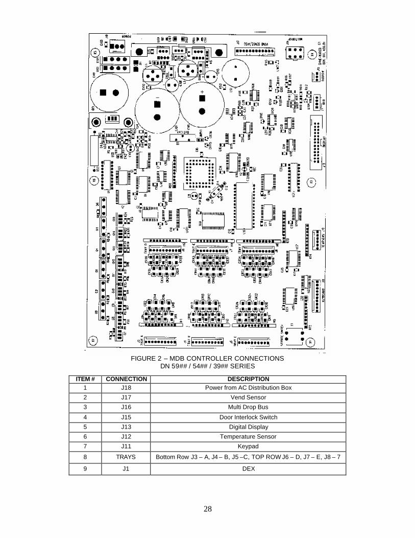
28
FIGURE 2 – MDB CONTROLLER CONNECTIONS
DN 59## / 54## / 39## SERIES
ITEM # CONNECTION DESCRIPTION 1 J18 Power from AC Distribution Box
2 J17 Vend Sensor
3 J16 Multi Drop Bus
4 J15 Door Interlock Switch
5 J13 Digital Display
6 J12 Temperature Sensor
7 J11 Keypad
8 TRAYS Bottom Row J3 – A, J4 – B, J5 –C, TOP ROW J6 – D, J7 – E, J8 – 7
9 J1 DEX
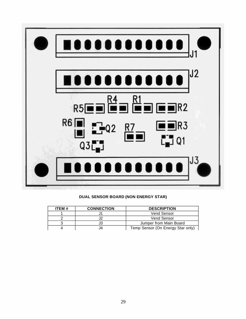
29
DUAL SENSOR BOARD (NON ENERGY STAR)
ITEM # CONNECTION DESCRIPTION 1 J1 Vend Sensor 2 J2 Vend Sensor 3 J3 Jumper from Main Board 4 J4 Temp Sensor (On Energy Star only)
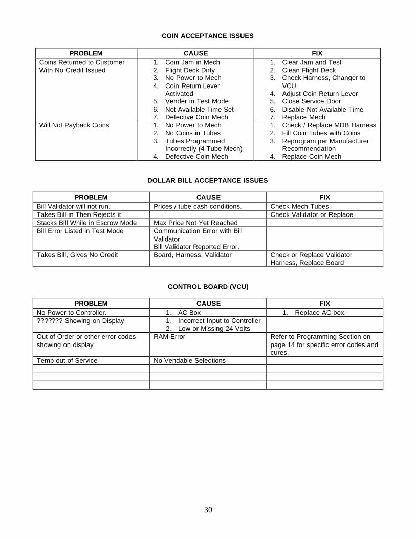
30
COIN ACCEPTANCE ISSUES
PROBLEM CAUSE FIX
Coins Returned to Customer With No Credit Issued
1. Coin Jam in Mech 2. Flight Deck Dirty 3. No Power to Mech 4. Coin Return Lever
Activated 5. Vender in Test Mode 6. Not Available Time Set 7. Defective Coin Mech
1. Clear Jam and Test 2. Clean Flight Deck 3. Check Harness, Changer to
VCU 4. Adjust Coin Return Lever 5. Close Service Door 6. Disable Not Available Time 7. Replace Mech
Will Not Payback Coins 1. No Power to Mech 2. No Coins in Tubes 3. Tubes Programmed
Incorrectly (4 Tube Mech) 4. Defective Coin Mech
1. Check / Replace MDB Harness 2. Fill Coin Tubes with Coins 3. Reprogram per Manufacturer
Recommendation 4. Replace Coin Mech
DOLLAR BILL ACCEPTANCE ISSUES
PROBLEM CAUSE FIX Bill Validator will not run. Prices / tube cash conditions. Check Mech Tubes. Takes Bill in Then Rejects it Check Validator or Replace Stacks Bill While in Escrow Mode Max Price Not Yet Reached Bill Error Listed in Test Mode Communication Error with Bill
Validator. Bill Validator Reported Error.
Takes Bill, Gives No Credit Board, Harness, Validator Check or Replace Validator Harness, Replace Board
CONTROL BOARD (VCU)
PROBLEM CAUSE FIX No Power to Controller. 1. AC Box 1. Replace AC box. ??????? Showing on Display 1. Incorrect Input to Controller
2. Low or Missing 24 Volts
Out of Order or other error codes showing on display
RAM Error Refer to Programming Section on page 14 for specific error codes and cures.
Temp out of Service No Vendable Selections
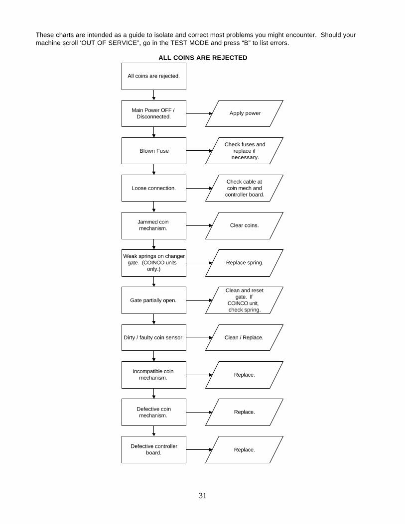
31
These charts are intended as a guide to isolate and correct most problems you might encounter. Should your machine scroll ‘OUT OF SERVICE”, go in the TEST MODE and press “B” to list errors.
ALL COINS ARE REJECTED
All coins are rejected.
Main Power OFF /Disconnected.
Apply power
Blown FuseCheck fuses and
replace ifnecessary.
Loose connection.Check cable atcoin mech and
controller board.
Jammed coinmechanism. Clear coins.
Weak springs on changergate. (COINCO units
only.)Replace spring.
Gate partially open.
Clean and resetgate. If
COINCO unit,check spring.
Dirty / faulty coin sensor. Clean / Replace.
Incompatible coinmechanism. Replace.
Defective coinmechanism.
Replace.
Defective controllerboard. Replace.
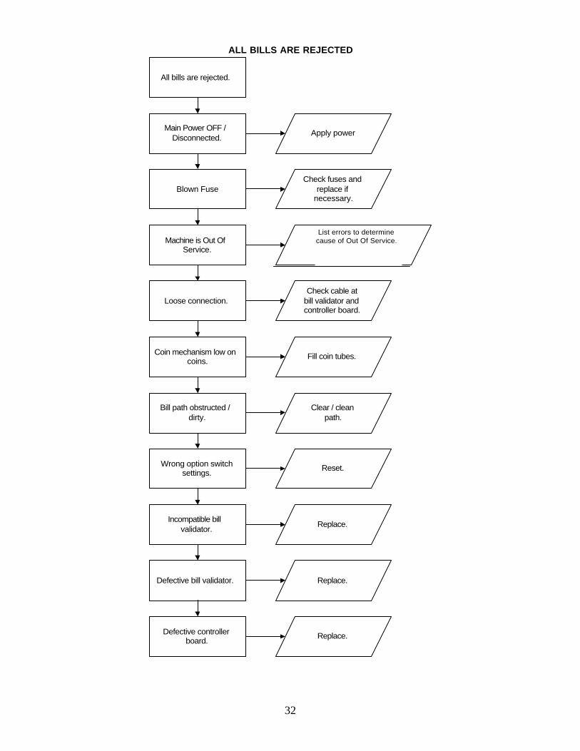
32
ALL BILLS ARE REJECTED
All bills are rejected.
Main Power OFF /Disconnected.
Apply power
Blown FuseCheck fuses and
replace ifnecessary.
Machine is Out OfService.
List errors to determinecause of Out Of Service.Refer to pg. 13 for error
explanations.
Loose connection.Check cable at
bill validator andcontroller board.
Coin mechanism low oncoins.
Fill coin tubes.
Bill path obstructed /dirty.
Clear / cleanpath.
Wrong option switchsettings.
Reset.
Incompatible billvalidator.
Replace.
Defective bill validator. Replace.
Defective controllerboard.
Replace.
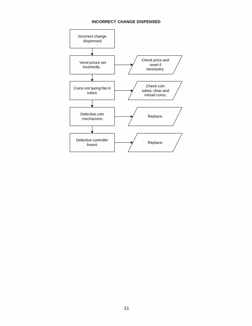
33
INCORRECT CHANGE DISPENSED
Incorrect changedispensed.
Vend prices setincorrectly.
Check price andreset if
necessary.
Coins not laying flat intubes.
Check cointubes; clear and
reload coins.
Defective coinmechanism.
Replace.
Defective controllerboard. Replace.
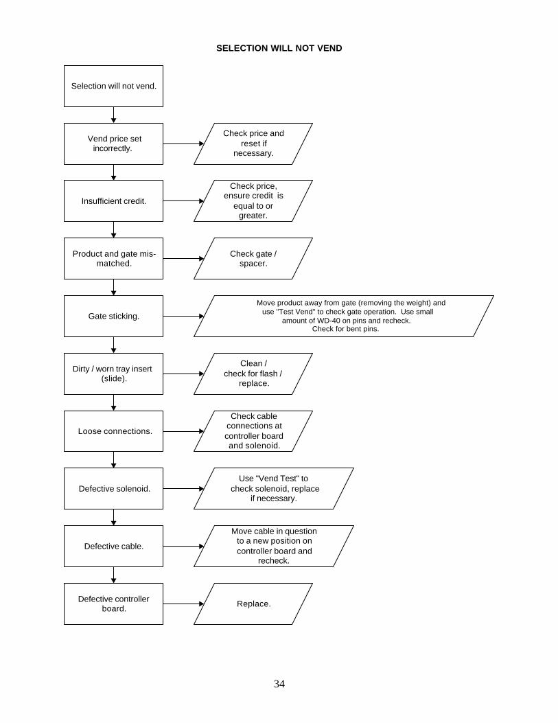
34
SELECTION WILL NOT VEND
Selection will not vend.
Vend price setincorrectly.
Check price andreset if
necessary.
Insufficient credit.
Check price,ensure credit is
equal to orgreater.
Product and gate mis-matched.
Check gate /spacer.
Gate sticking.
Move product away from gate (removing the weight) anduse "Test Vend" to check gate operation. Use small
amount of WD-40 on pins and recheck.Check for bent pins.
Dirty / worn tray insert(slide).
Clean /check for flash /
replace.
Loose connections.
Check cableconnections atcontroller boardand solenoid.
Defective solenoid.Use "Vend Test" to
check solenoid, replaceif necessary.
Defective cable.
Move cable in questionto a new position oncontroller board and
recheck.
Defective controllerboard. Replace.
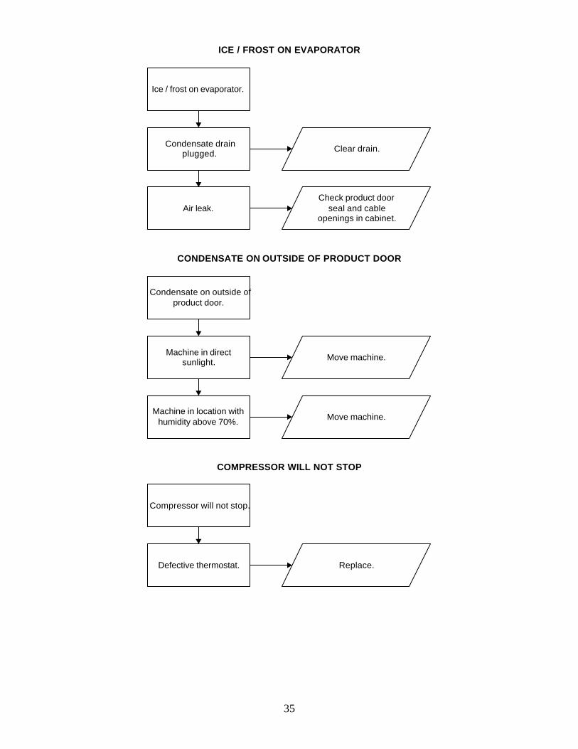
35
ICE / FROST ON EVAPORATOR
Ice / frost on evaporator.
Condensate drainplugged. Clear drain.
Air leak.Check product door
seal and cableopenings in cabinet.
CONDENSATE ON OUTSIDE OF PRODUCT DOOR
Condensate on outside ofproduct door.
Machine in directsunlight. Move machine.
Machine in location withhumidity above 70%. Move machine.
COMPRESSOR WILL NOT STOP
Compressor will not stop.
Defective thermostat. Replace.
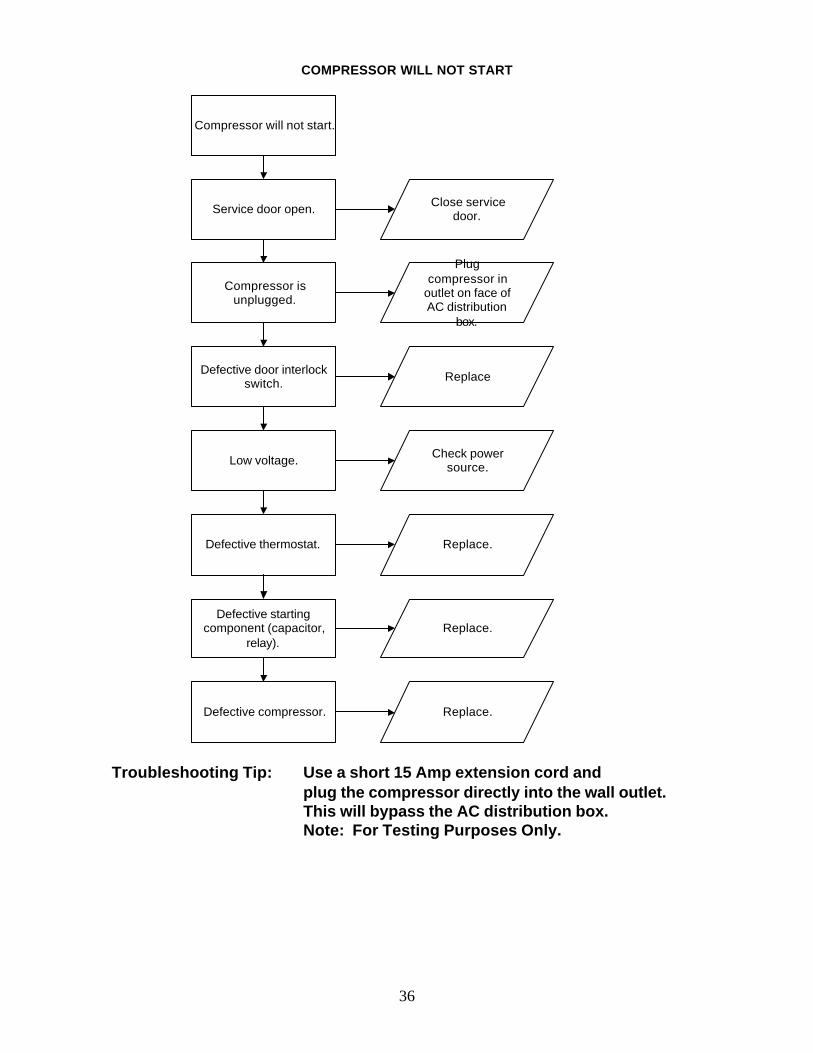
36
COMPRESSOR WILL NOT START
Compressor will not start.
Service door open. Close servicedoor.
Compressor isunplugged.
Plugcompressor in
outlet on face ofAC distribution
box.
Defective door interlockswitch. Replace
Low voltage. Check powersource.
Defective thermostat. Replace.
Defective startingcomponent (capacitor,
relay).Replace.
Defective compressor. Replace.
Troubleshooting Tip: Use a short 15 Amp extension cord andplug the compressor directly into the wall outlet.This will bypass the AC distribution box.Note: For Testing Purposes Only.
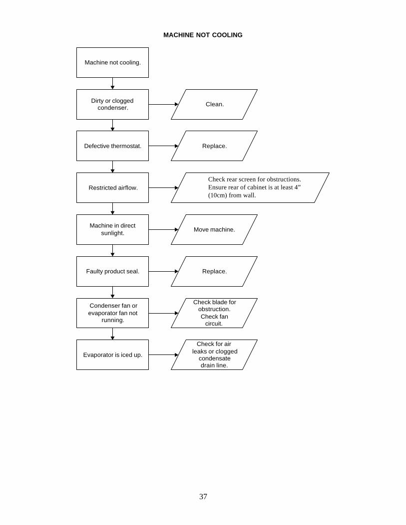
37
MACHINE NOT COOLING
Machine not cooling.
Dirty or cloggedcondenser. Clean.
Defective thermostat. Replace.
Restricted airflow.
Check rear screen forobstructions. Ensure rear of
cabinet is at least 3.25" (82.6 mm)from wall.
Machine in directsunlight. Move machine.
Faulty product seal. Replace.
Condenser fan orevaporator fan not
running.
Check blade forobstruction.Check fan
circuit.
Evaporator is iced up.
Check for airleaks or clogged
condensatedrain line.
Check rear screen for obstructions. Ensure rear of cabinet is at least 4” (10cm) from wall.
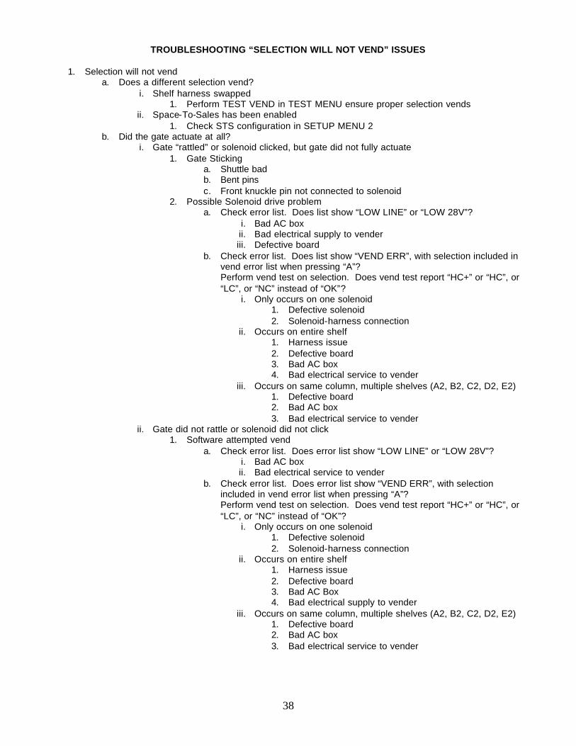
38
TROUBLESHOOTING “SELECTION WILL NOT VEND” ISSUES
1. Selection will not vend
a. Does a different selection vend? i. Shelf harness swapped
1. Perform TEST VEND in TEST MENU ensure proper selection vends ii. Space-To-Sales has been enabled
1. Check STS configuration in SETUP MENU 2 b. Did the gate actuate at all?
i. Gate “rattled” or solenoid clicked, but gate did not fully actuate 1. Gate Sticking
a. Shuttle bad b. Bent pins c. Front knuckle pin not connected to solenoid
2. Possible Solenoid drive problem a. Check error list. Does list show “LOW LINE” or “LOW 28V”?
i. Bad AC box ii. Bad electrical supply to vender iii. Defective board
b. Check error list. Does list show “VEND ERR”, with selection included in vend error list when pressing “A”? Perform vend test on selection. Does vend test report “HC+” or “HC”, or “LC”, or “NC” instead of “OK”?
i. Only occurs on one solenoid 1. Defective solenoid 2. Solenoid-harness connection
ii. Occurs on entire shelf 1. Harness issue 2. Defective board 3. Bad AC box 4. Bad electrical service to vender
iii. Occurs on same column, multiple shelves (A2, B2, C2, D2, E2) 1. Defective board 2. Bad AC box 3. Bad electrical service to vender
ii. Gate did not rattle or solenoid did not click 1. Software attempted vend
a. Check error list. Does error list show “LOW LINE” or “LOW 28V”? i. Bad AC box ii. Bad electrical service to vender
b. Check error list. Does error list show “VEND ERR”, with selection included in vend error list when pressing “A”? Perform vend test on selection. Does vend test report “HC+” or “HC”, or “LC”, or “NC” instead of “OK”?
i. Only occurs on one solenoid 1. Defective solenoid 2. Solenoid-harness connection
ii. Occurs on entire shelf 1. Harness issue 2. Defective board 3. Bad AC Box 4. Bad electrical supply to vender
iii. Occurs on same column, multiple shelves (A2, B2, C2, D2, E2) 1. Defective board 2. Bad AC box 3. Bad electrical service to vender
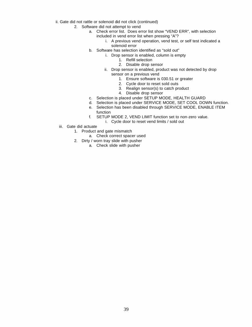
39
ii. Gate did not rattle or solenoid did not click (continued)
2. Software did not attempt to vend a. Check error list. Does error list show “VEND ERR”, with selection
included in vend error list when pressing “A”? i. A previous vend operation, vend test, or self test indicated a
solenoid error b. Software has selection identified as “sold out”
i. Drop sensor is enabled, column is empty 1. Refill selection 2. Disable drop sensor
ii. Drop sensor is enabled, product was not detected by drop sensor on a previous vend
1. Ensure software is 030.51 or greater 2. Cycle door to reset sold outs 3. Realign sensor(s) to catch product 4. Disable drop sensor
c. Selection is placed under SETUP MODE, HEALTH GUARD d. Selection is placed under SERVICE MODE, SET COOL DOWN function. e. Selection has been disabled through SERVICE MODE, ENABLE ITEM
function f. SETUP MODE 2, VEND LIMIT function set to non-zero value.
i. Cycle door to reset vend limits / sold out iii. Gate did actuate
1. Product and gate mismatch a. Check correct spacer used
2. Dirty / worn tray slide with pusher a. Check slide with pusher
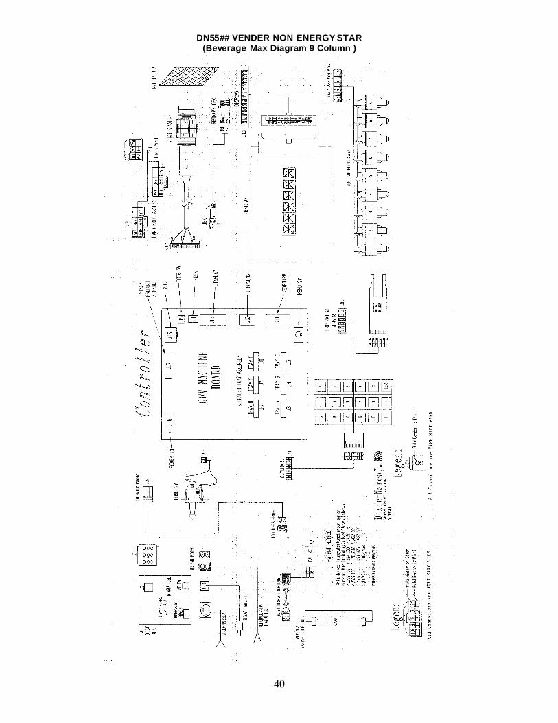
40
DN55## VENDER NON ENERGY STAR (Beverage Max Diagram 9 Column )
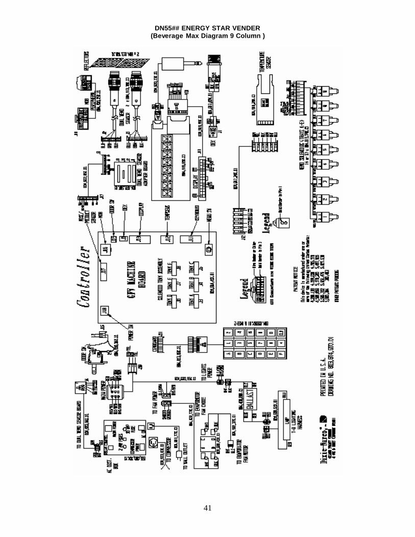
41
DN55## ENERGY STAR VENDER (Beverage Max Diagram 9 Column )
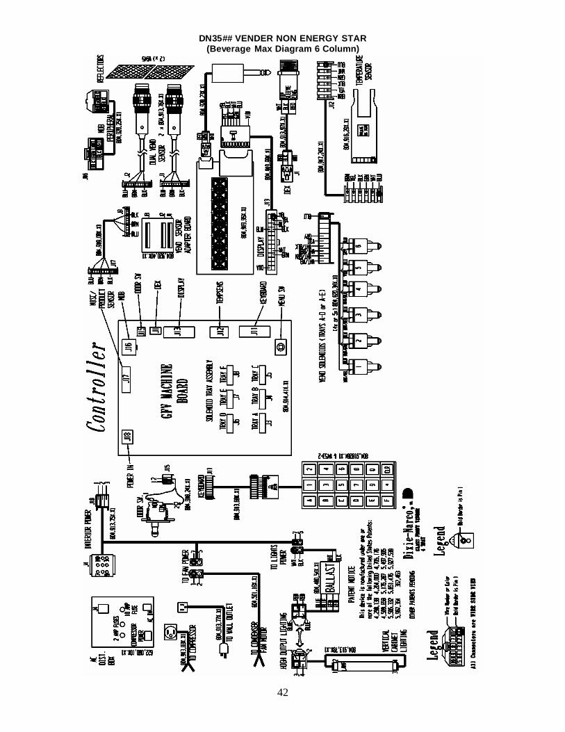
42
DN35## VENDER NON ENERGY STAR (Beverage Max Diagram 6 Column)
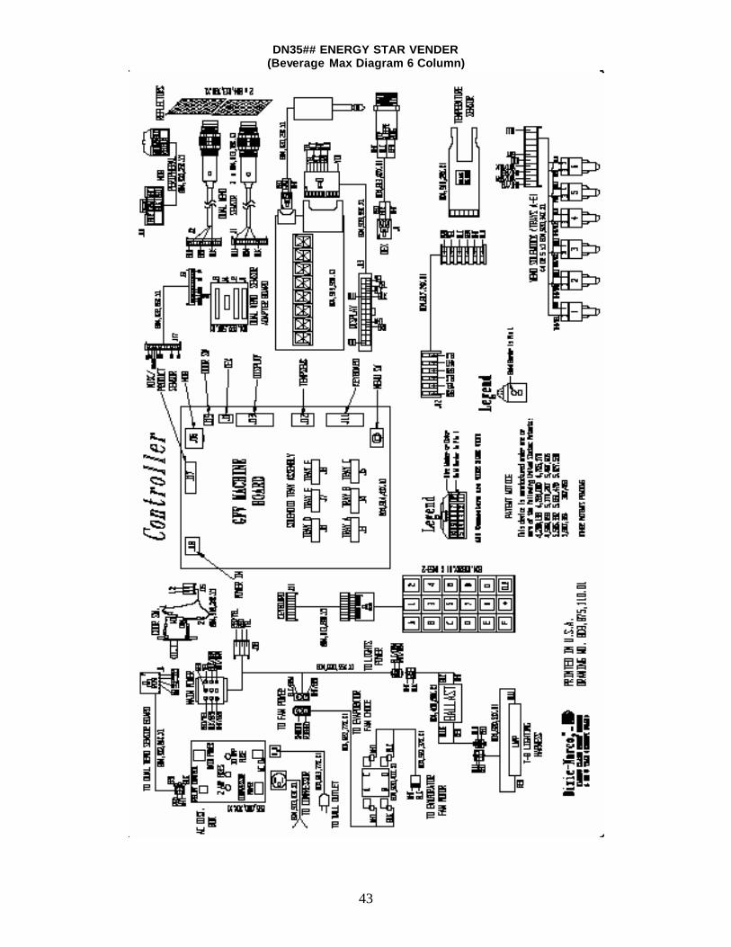
43
DN35## ENERGY STAR VENDER (Beverage Max Diagram 6 Column)
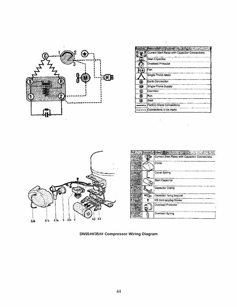
44
DN55##/35## Compressor Wiring Diagram
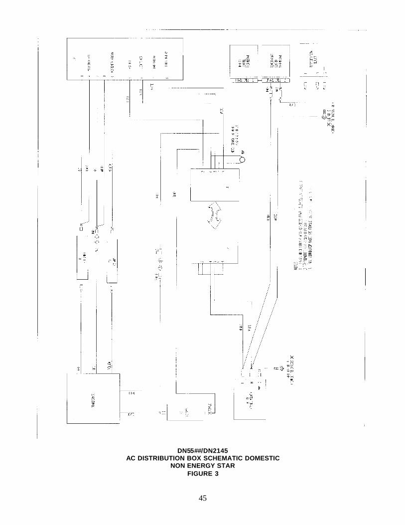
45
DN55##/DN2145 AC DISTRIBUTION BOX SCHEMATIC DOMESTIC
NON ENERGY STAR FIGURE 3
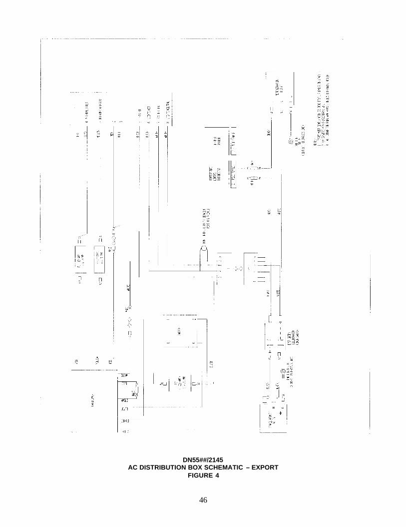
46
DN55##/2145 AC DISTRIBUTION BOX SCHEMATIC – EXPORT
FIGURE 4
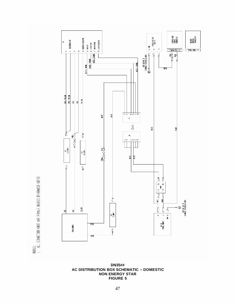
47
DN35##
AC DISTRIBUTION BOX SCHEMATIC – DOMESTIC NON ENERGY STAR
FIGURE 5
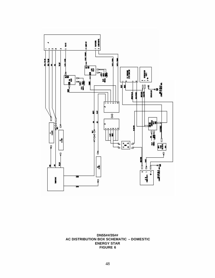
48
DN55##/35## AC DISTRIBUTION BOX SCHEMATIC – DOMESTIC
ENERGY STAR FIGURE 6
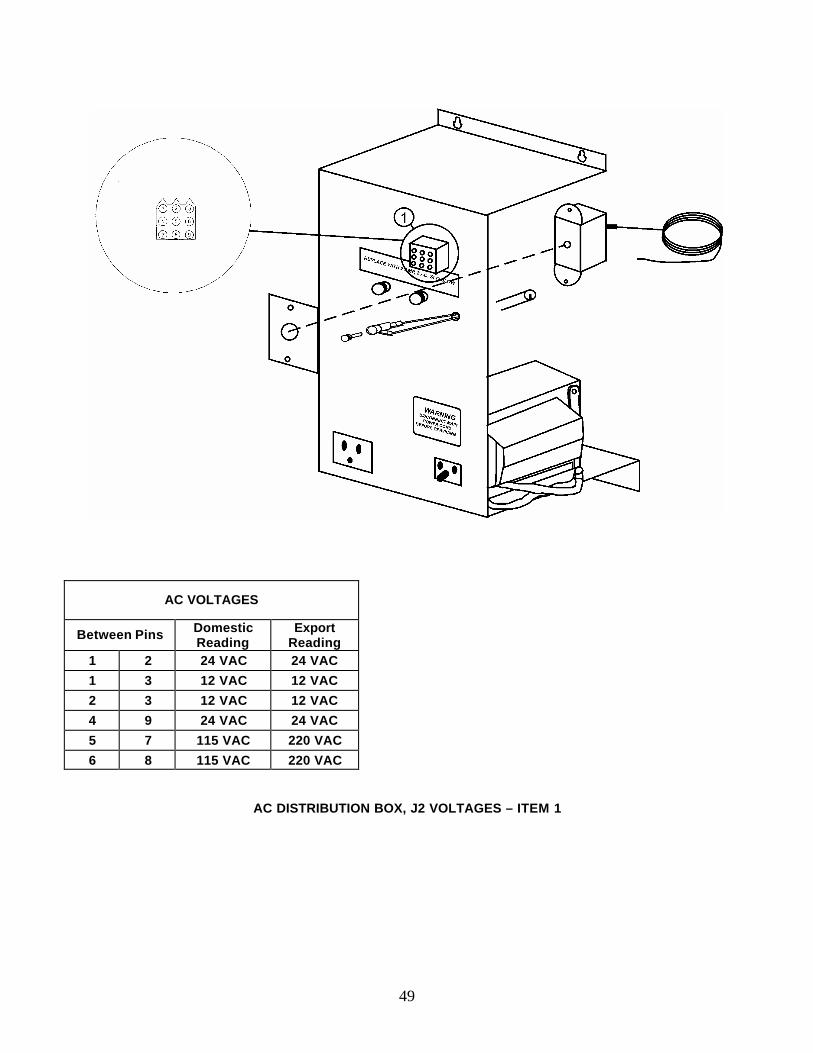
49
AC VOLTAGES
Between Pins Domestic Reading
Export Reading
1 2 24 VAC 24 VAC
1 3 12 VAC 12 VAC
2 3 12 VAC 12 VAC
4 9 24 VAC 24 VAC
5 7 115 VAC 220 VAC
6 8 115 VAC 220 VAC
AC DISTRIBUTION BOX, J2 VOLTAGES – ITEM 1
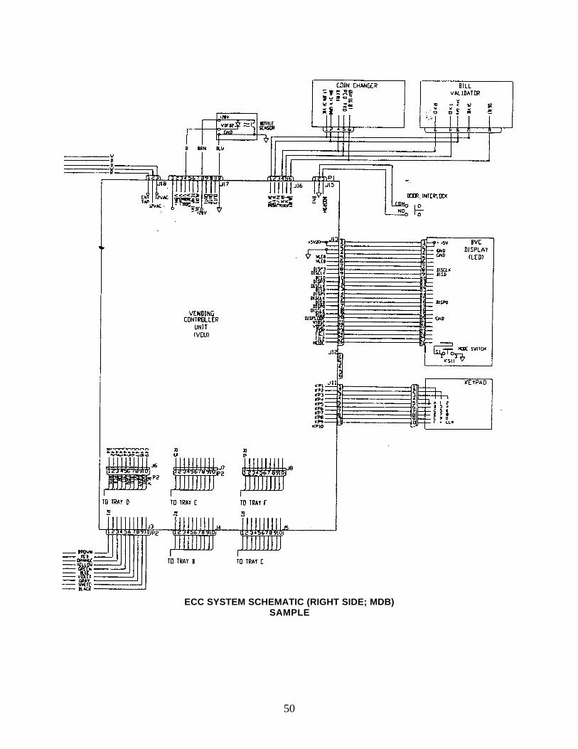
50
ECC SYSTEM SCHEMATIC (RIGHT SIDE; MDB)
SAMPLE
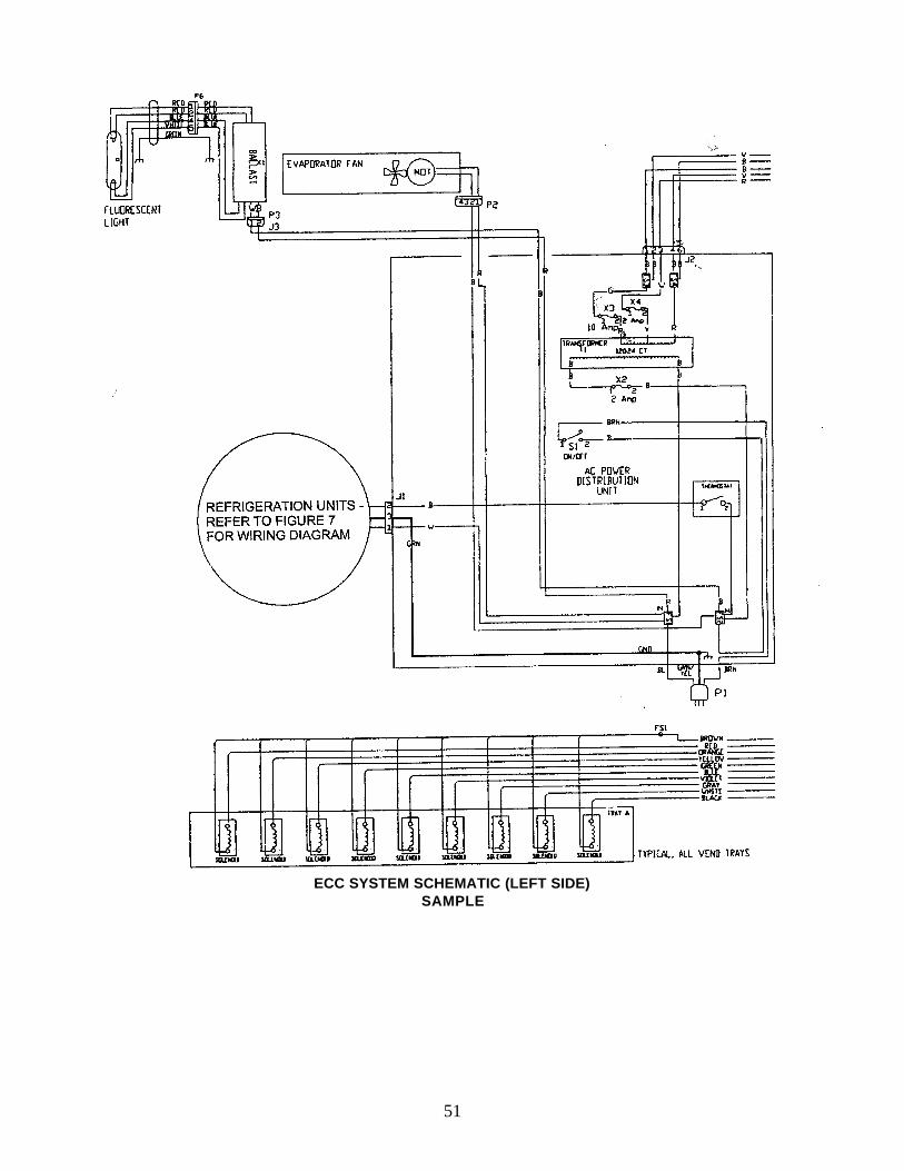
51
ECC SYSTEM SCHEMATIC (LEFT SIDE)
SAMPLE
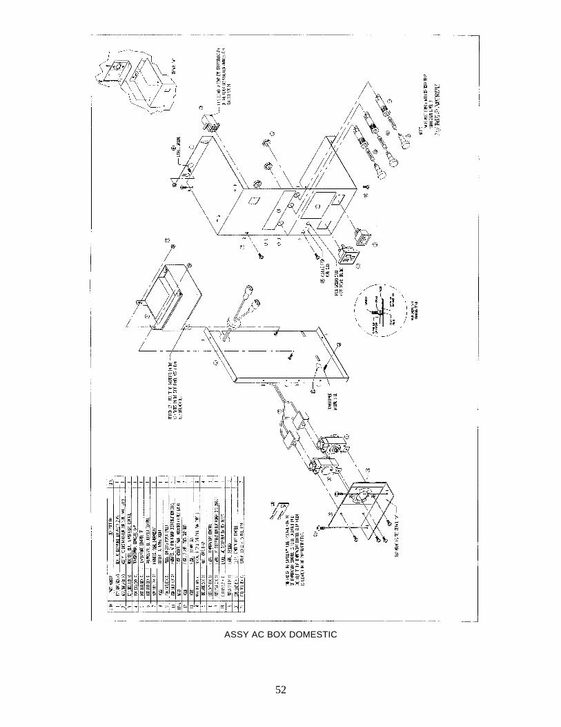
52
ASSY AC BOX DOMESTIC
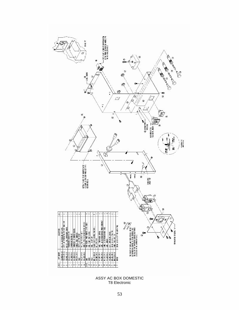
53
ASSY AC BOX DOMESTIC
T8 Electronic
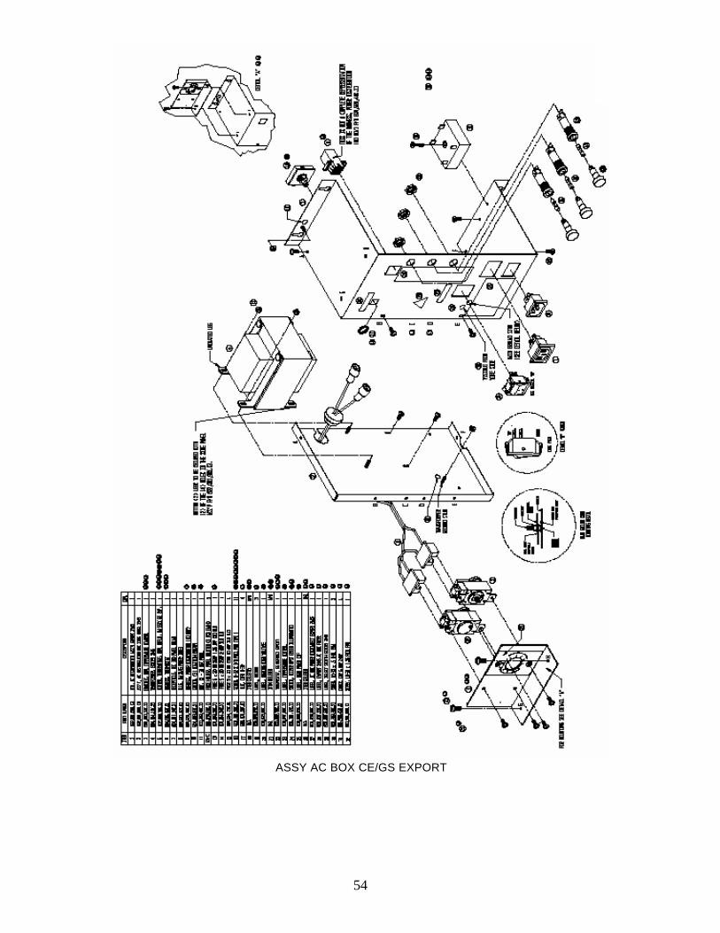
54
ASSY AC BOX CE/GS EXPORT
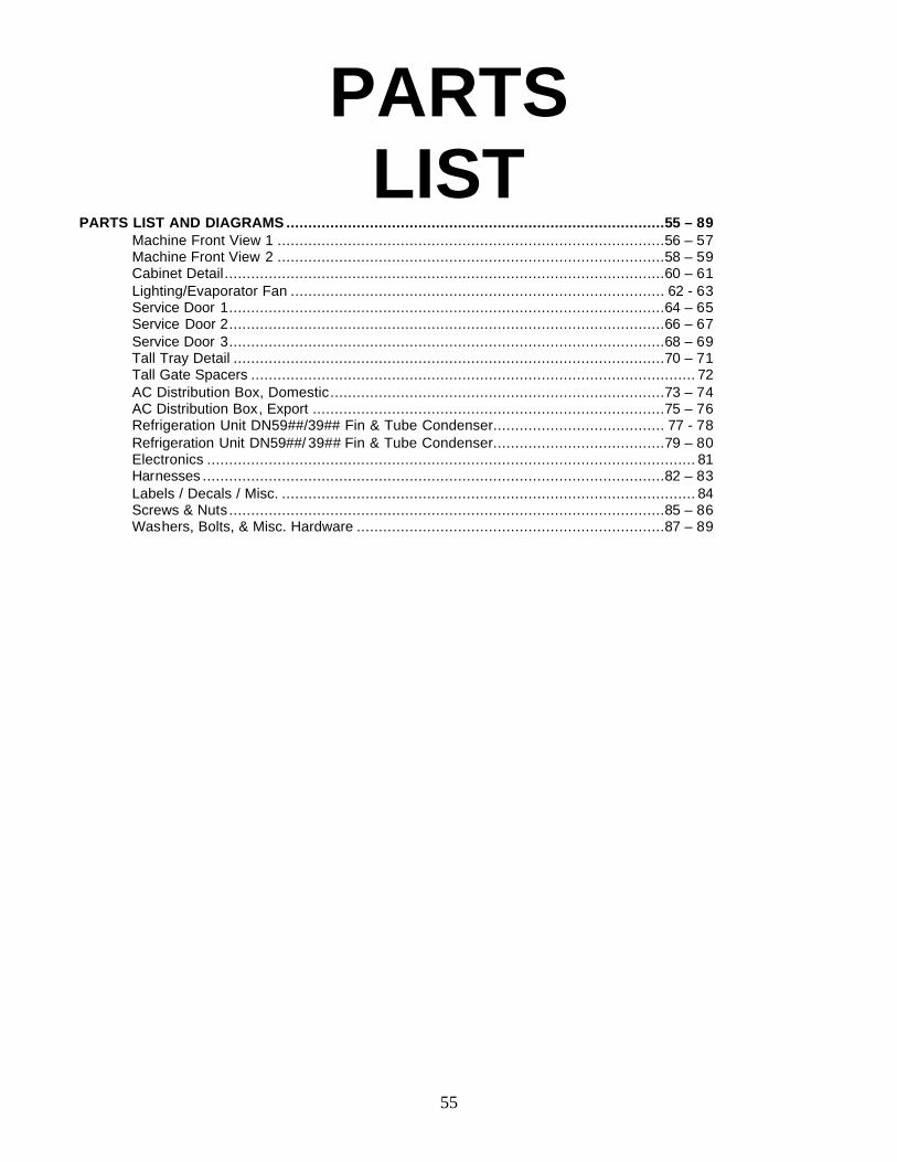
55
PARTS LIST
PARTS LIST AND DIAGRAMS ......................................................................................55 – 89 Machine Front View 1 ........................................................................................56 – 57 Machine Front View 2 ........................................................................................58 – 59 Cabinet Detail....................................................................................................60 – 61 Lighting/Evaporator Fan ..................................................................................... 62 - 63 Service Door 1...................................................................................................64 – 65 Service Door 2...................................................................................................66 – 67 Service Door 3...................................................................................................68 – 69 Tall Tray Detail ..................................................................................................70 – 71 Tall Gate Spacers ..................................................................................................... 72 AC Distribution Box, Domestic............................................................................73 – 74 AC Distribution Box, Export ................................................................................75 – 76 Refrigeration Unit DN59##/39## Fin & Tube Condenser....................................... 77 - 78 Refrigeration Unit DN59##/ 39## Fin & Tube Condenser.......................................79 – 80 Electronics ............................................................................................................... 81 Harnesses .........................................................................................................82 – 83 Labels / Decals / Misc. .............................................................................................. 84 Screws & Nuts ...................................................................................................85 – 86 Washers, Bolts, & Misc. Hardware ......................................................................87 – 89
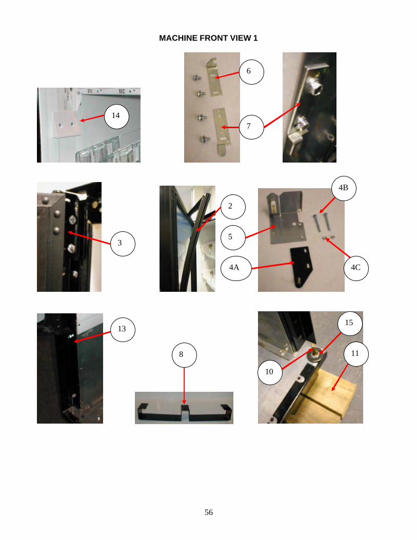
56
MACHINE FRONT VIEW 1
14
6
7
3 5
2
4A
4B
4C
13
10
11
15
8
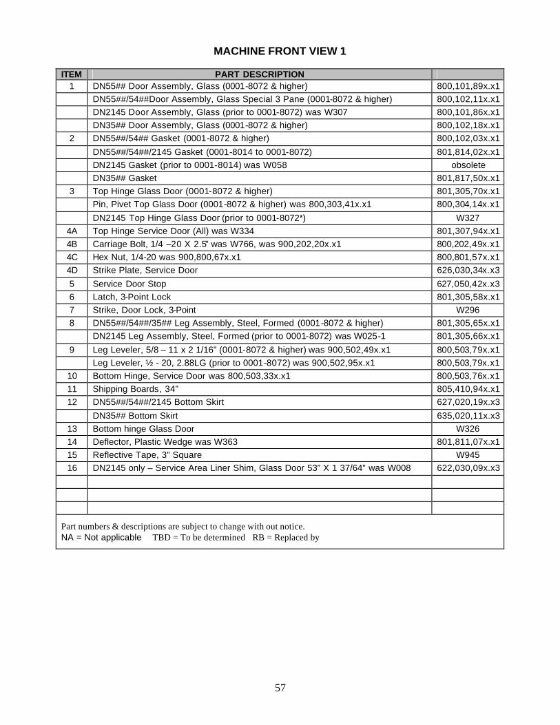
57
MACHINE FRONT VIEW 1
ITEM PART DESCRIPTION
1 DN55## Door Assembly, Glass (0001-8072 & higher) 800,101,89x.x1 DN55##/54##Door Assembly, Glass Special 3 Pane (0001-8072 & higher) 800,102,11x.x1 DN2145 Door Assembly, Glass (prior to 0001-8072) was W307 800,101,86x.x1 DN35## Door Assembly, Glass (0001-8072 & higher) 800,102,18x.x1
2 DN55##/54## Gasket (0001-8072 & higher) 800,102,03x.x1
DN55##/54##/2145 Gasket (0001-8014 to 0001-8072) 801,814,02x.x1 DN2145 Gasket (prior to 0001-8014) was W058 obsolete DN35## Gasket 801,817,50x.x1
3 Top Hinge Glass Door (0001-8072 & higher) 801,305,70x.x1 Pin, Pivet Top Glass Door (0001-8072 & higher) was 800,303,41x.x1 800,304,14x.x1
DN2145 Top Hinge Glass Door (prior to 0001-8072*) W327 4A Top Hinge Service Door (All) was W334 801,307,94x.x1 4B Carriage Bolt, 1/4 –20 X 2.5” was W766, was 900,202,20x.x1 800,202,49x.x1 4C Hex Nut, 1/4-20 was 900,800,67x.x1 800,801,57x.x1 4D Strike Plate, Service Door 626,030,34x.x3
5 Service Door Stop 627,050,42x.x3 6 Latch, 3-Point Lock 801,305,58x.x1 7 Strike, Door Lock, 3-Point W296 8 DN55##/54##/35## Leg Assembly, Steel, Formed (0001-8072 & higher) 801,305,65x.x1 DN2145 Leg Assembly, Steel, Formed (prior to 0001-8072) was W025-1 801,305,66x.x1
9 Leg Leveler, 5/8 – 11 x 2 1/16” (0001-8072 & higher) was 900,502,49x.x1 800,503,79x.x1 Leg Leveler, ½ - 20, 2.88LG (prior to 0001-8072) was 900,502,95x.x1 800,503,79x.x1
10 Bottom Hinge, Service Door was 800,503,33x.x1 800,503,76x.x1 11 Shipping Boards, 34” 805,410,94x.x1 12 DN55##/54##/2145 Bottom Skirt 627,020,19x.x3
DN35## Bottom Skirt 635,020,11x.x3 13 Bottom hinge Glass Door W326 14 Deflector, Plastic Wedge was W363 801,811,07x.x1 15 Reflective Tape, 3” Square W945 16 DN2145 only – Service Area Liner Shim, Glass Door 53” X 1 37/64” was W008 622,030,09x.x3
Part numbers & descriptions are subject to change with out notice. NA = Not applicable TBD = To be determined RB = Replaced by
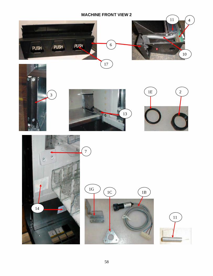
58
MACHINE FRONT VIEW 2
7
14
3
13
2 1E
1C
11
1B
6
10
11
1G
4
17
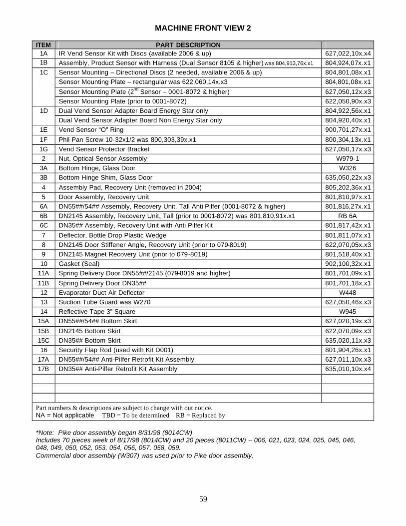
59
MACHINE FRONT VIEW 2
ITEM PART DESCRIPTION 1A IR Vend Sensor Kit with Discs (available 2006 & up) 627,022,10x.x4 1B
a10B Assembly, Product Sensor with Harness (Dual Sensor 8105 & higher) was 804,913,76x.x1 804,924,07x.x1
1C Sensor Mounting – Directional Discs (2 needed, available 2006 & up) 804,801,08x.x1 Sensor Mounting Plate – rectangular was 622,060,14x.x3 804,801,08x.x1
Sensor Mounting Plate (2nd Sensor – 0001-8072 & higher) 627,050,12x.x3 Sensor Mounting Plate (prior to 0001-8072) 622,050,90x.x3
1D Dual Vend Sensor Adapter Board Energy Star only 804,922,56x.x1 Dual Vend Sensor Adapter Board Non Energy Star only 804,920,40x.x1
1E Vend Sensor “O” Ring 900,701,27x.x1
1F Phil Pan Screw 10-32x1/2 was 800,303,39x.x1 800,304,13x.x1 1G Vend Sensor Protector Bracket 627,050,17x.x3 2 Nut, Optical Sensor Assembly W979-1
3A Bottom Hinge, Glass Door W326 3B Bottom Hinge Shim, Glass Door 635,050,22x.x3
4 Assembly Pad, Recovery Unit (removed in 2004) 805,202,36x.x1 5 Door Assembly, Recovery Unit 801,810,97x.x1
6A DN55##/54## Assembly, Recovery Unit, Tall Anti Pilfer (0001-8072 & higher) 801,816,27x.x1 6B DN2145 Assembly, Recovery Unit, Tall (prior to 0001-8072) was 801,810,91x.x1 RB 6A 6C DN35## Assembly, Recovery Unit with Anti Pilfer Kit 801,817,42x.x1
7 Deflector, Bottle Drop Plastic Wedge 801,811,07x.x1 8 DN2145 Door Stiffener Angle, Recovery Unit (prior to 079-8019) 622,070,05x.x3 9 DN2145 Magnet Recovery Unit (prior to 079-8019) 801,518,40x.x1 10 Gasket (Seal) 902,100,32x.x1
11A Spring Delivery Door DN55##/2145 (079-8019 and higher) 801,701,09x.x1
11B Spring Delivery Door DN35## 801,701,18x.x1 12 Evaporator Duct Air Deflector W448 13 Suction Tube Guard was W270 627,050,46x.x3 14 Reflective Tape 3” Square W945
15A DN55##/54## Bottom Skirt 627,020,19x.x3
15B DN2145 Bottom Skirt 622,070,09x.x3 15C DN35## Bottom Skirt 635,020,11x.x3 16 Security Flap Rod (used with Kit D001) 801,904,26x.x1
17A DN55##/54## Anti-Pilfer Retrofit Kit Assembly 627,011,10x.x3 17B DN35## Anti-Pilfer Retrofit Kit Assembly 635,010,10x.x4
Part numbers & descriptions are subject to change with out notice. NA = Not applicable TBD = To be determined RB = Replaced by *Note: Pike door assembly began 8/31/98 (8014CW) Includes 70 pieces week of 8/17/98 (8014CW) and 20 pieces (8011CW) – 006, 021, 023, 024, 025, 045, 046, 048, 049, 050, 052, 053, 054, 056, 057, 058, 059. Commercial door assembly (W307) was used prior to Pike door assembly.
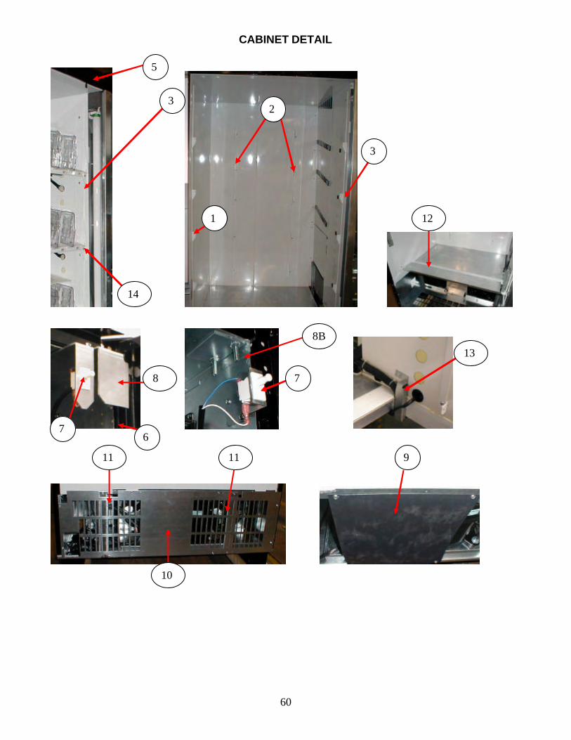
60
CABINET DETAIL
14
3
9
12
3
1
2
7
8
8B
7
10
11 11
13
5
6

61
CABINET DETAIL
ITEM PART DESCRIPTION 1 Left Tray Mounting Bracket, Domestic DN5591/3591 627,070,21x.x3 Left Tray Mounting Bracket, Domestic DN5592/3592 was 627,070,08x.x3 627,070,28x.x3 Left Tray Mounting Bracket, Domestic DN5593 was 627,070,12x.x3 627,070,34x.x3 Left Tray Mounting Bracket, Domestic DN5594/3594
5 627,070,25x.x3
Left Tray Mounting Bracket, Domestic DN2145 622,070,02x.x3 Left Tray Mounting Bracket, Export DN2145 622,050,35x.x3 Left Tray Mounting Bracket, Mexico 600ml DN2145 (4 shelf) 622,050,36x.x3
2 Rear Tray Support Bracket, Domestic DN5591/3591 627,070,23x.x3 Rear Tray Support Bracket, Domestic DN5592/3592 was 627,070,07x.x3 627,070,31x.x3
Rear Tray Support Bracket, Domestic DN5593 was 627,070,11x.x3 627,070,36x.x3 Rear Tray Support Bracket, Domestic DN5594/3594 627,070,27x.x3 Rear Tray Support Bracket, Domestic DN2145 D042 Rear Tray Support Bracket, Export DN2145 622,050,33x.x3 Rear Tray Support Bracket, Mexico 600ml DN2145 (4 shelf) 622,050,38x.x3
3 Right Tray Mounting Bracket, Domestic DN5591/3591 627,070,22x.x3 Right Tray Mounting Bracket, Domestic DN5592/3592 was 627,070,09x.x3 627,070,29x.x3 Right Tray Mounting Bracket, Domestic DN5593 was 627,070,13x.x3 627,070,35x.x3 Right Tray Mounting Bracket, Domestic DN5594/3594 627,070,26x.x3 Right Tray Mounting Bracket, Domestic 20 oz. DN2145 622,070,03x.x3
Right Tray Mounting Bracket, Export DN2145 622,050,34x.x3 Right Tray Mounting Bracket, Mexico 600 ml DN2145 (4 shelf) 622,050,37x.x3
4 DN55## /35## Security Angle Hinge, Left 627,020,11x.x3 DN2145 Security Angle Hinge, Left 622,060,06x.x3
5 DN55## Security Angle Top 627,020,13x.x3
DN2145 Security Angle Top 622,050,04x.x3 DN35## Security Angle Top 635,020,06x.x3
6 Security Angle Right DN55##/35## 627,020,12x.x3 Security Angle, Right DN2145 622,060,07x.x3
7 Switch Door 804,100,77x.x1
8A Service Door Stop & Door Switch Bracket 622,060,05x.x3 8B Door Switch Bracket RB 8A 9 Rear Plate 801,903,56x.x1
10A Ingress Guard DN55##(Export not shown) 622,050,39x.x3 10B Ingress Guard DN35## 635,050,13x.x3
11 Brace, Rear Base Plate 622,020,08x.x3 12 DN55##/54##/2145 Bottom Tray Guard 627,071,10x.x3 DN35## Bottom Tray Guard 635,070,60x.x3
13 Suction Tube Guard was W270 627,050,46x.x3 14 Screw, Tray Support #8-18X1/2 self drilling was 900,301,50x.x1 800,304,18x.x1
Part numbers & descriptions are subject to change with out notice. NA = Not applicable TBD = To be determined RB = Replaced by
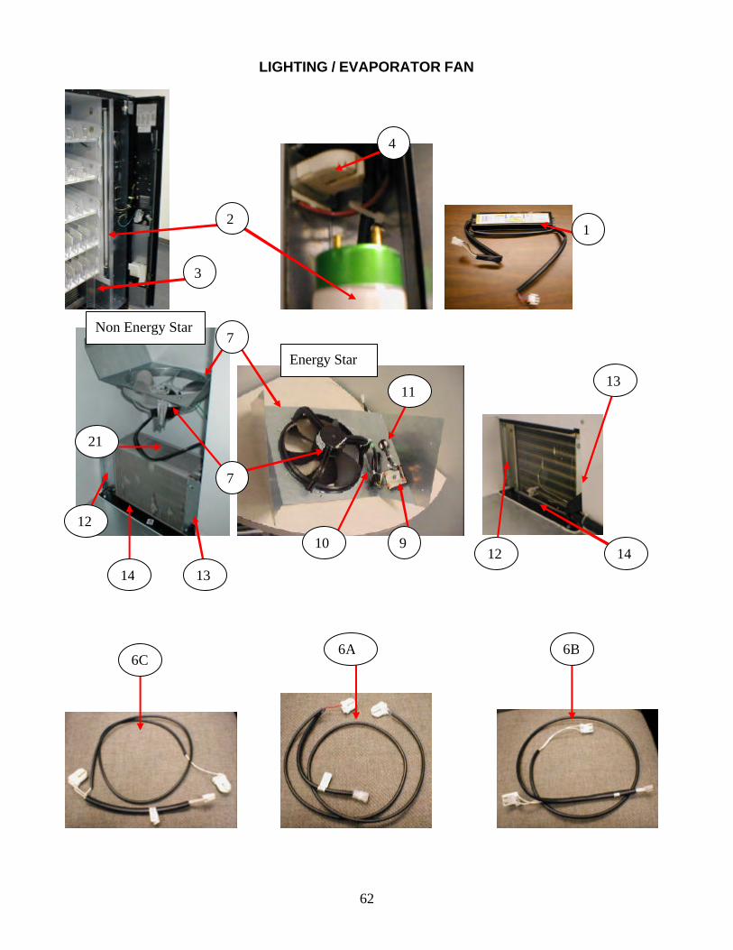
62
LIGHTING / EVAPORATOR FAN
21
4
2 1
13
12
3
7
7
13
12 9
11
10
14 14
6B 6A 6C
Non Energy Star
Energy Star
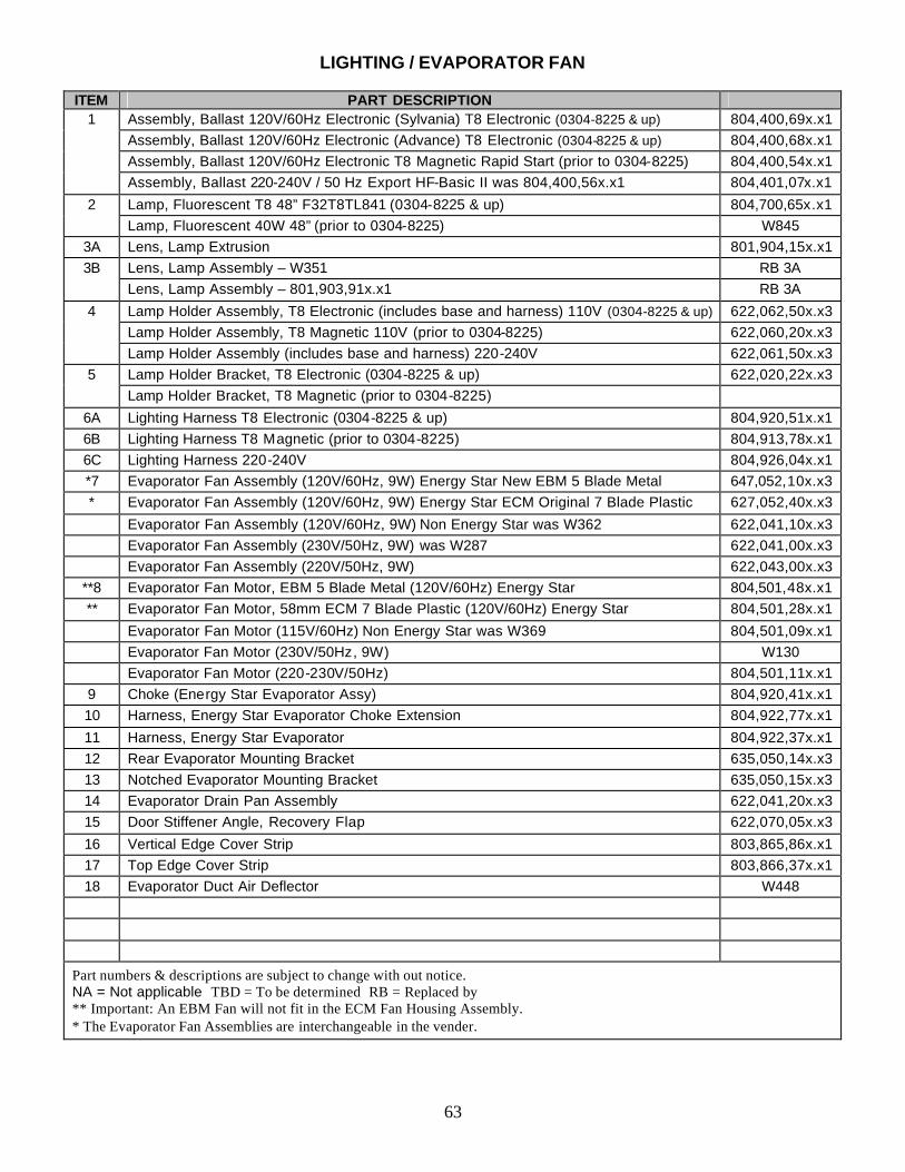
63
LIGHTING / EVAPORATOR FAN
ITEM PART DESCRIPTION 1 Assembly, Ballast 120V/60Hz Electronic (Sylvania) T8 Electronic (0304-8225 & up) 804,400,69x.x1 Assembly, Ballast 120V/60Hz Electronic (Advance) T8 Electronic (0304-8225 & up) 804,400,68x.x1 Assembly, Ballast 120V/60Hz Electronic T8 Magnetic Rapid Start (prior to 0304-8225) 804,400,54x.x1 Assembly, Ballast 220-240V / 50 Hz Export HF-Basic II was 804,400,56x.x1 804,401,07x.x1
2 Lamp, Fluorescent T8 48” F32T8TL841 (0304-8225 & up) 804,700,65x.x1 Lamp, Fluorescent 40W 48” (prior to 0304-8225) W845
3A Lens, Lamp Extrusion 801,904,15x.x1 3B Lens, Lamp Assembly – W351 RB 3A
Lens, Lamp Assembly – 801,903,91x.x1 RB 3A
4 Lamp Holder Assembly, T8 Electronic (includes base and harness) 110V (0304-8225 & up) 622,062,50x.x3 Lamp Holder Assembly, T8 Magnetic 110V (prior to 0304-8225) 622,060,20x.x3 Lamp Holder Assembly (includes base and harness) 220-240V 622,061,50x.x3
5 Lamp Holder Bracket, T8 Electronic (0304-8225 & up) 622,020,22x.x3 Lamp Holder Bracket, T8 Magnetic (prior to 0304-8225)
6A Lighting Harness T8 Electronic (0304-8225 & up) 804,920,51x.x1 6B Lighting Harness T8 Magnetic (prior to 0304-8225) 804,913,78x.x1 6C Lighting Harness 220-240V 804,926,04x.x1 *7 Evaporator Fan Assembly (120V/60Hz, 9W) Energy Star New EBM 5 Blade Metal 647,052,10x.x3 * Evaporator Fan Assembly (120V/60Hz, 9W) Energy Star ECM Original 7 Blade Plastic 627,052,40x.x3
Evaporator Fan Assembly (120V/60Hz, 9W) Non Energy Star was W362 622,041,10x.x3 Evaporator Fan Assembly (230V/50Hz, 9W) was W287 622,041,00x.x3 Evaporator Fan Assembly (220V/50Hz, 9W) 622,043,00x.x3
**8 Evaporator Fan Motor, EBM 5 Blade Metal (120V/60Hz) Energy Star 804,501,48x.x1 ** Evaporator Fan Motor, 58mm ECM 7 Blade Plastic (120V/60Hz) Energy Star 804,501,28x.x1
Evaporator Fan Motor (115V/60Hz) Non Energy Star was W369 804,501,09x.x1 Evaporator Fan Motor (230V/50Hz, 9W) W130 Evaporator Fan Motor (220-230V/50Hz) 804,501,11x.x1
9 Choke (Energy Star Evaporator Assy) 804,920,41x.x1 10 Harness, Energy Star Evaporator Choke Extension 804,922,77x.x1
11 Harness, Energy Star Evaporator 804,922,37x.x1 12 Rear Evaporator Mounting Bracket 635,050,14x.x3 13 Notched Evaporator Mounting Bracket 635,050,15x.x3 14 Evaporator Drain Pan Assembly 622,041,20x.x3 15 Door Stiffener Angle, Recovery Flap 622,070,05x.x3
16 Vertical Edge Cover Strip 803,865,86x.x1 17 Top Edge Cover Strip 803,866,37x.x1 18 Evaporator Duct Air Deflector W448
Part numbers & descriptions are subject to change with out notice. NA = Not applicable TBD = To be determined RB = Replaced by ** Important: An EBM Fan will not fit in the ECM Fan Housing Assembly. * The Evaporator Fan Assemblies are interchangeable in the vender.
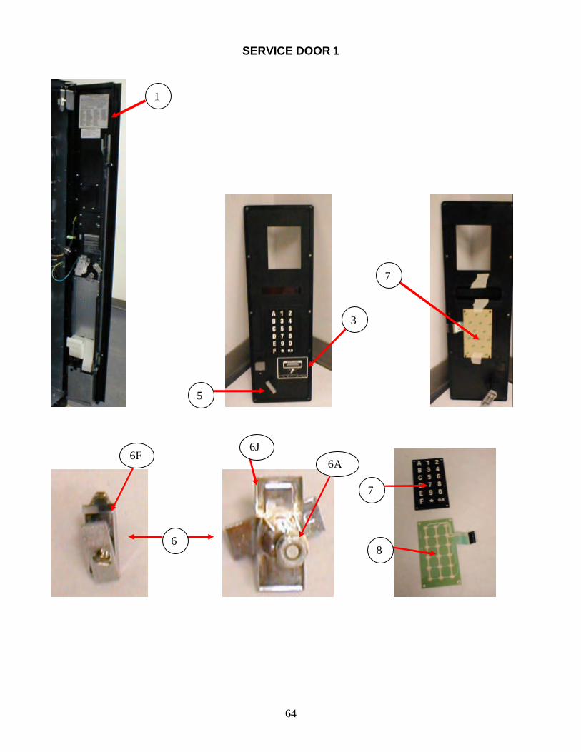
64
SERVICE DOOR 1
1
5
6
7
8
6F 6J
3
6A
7
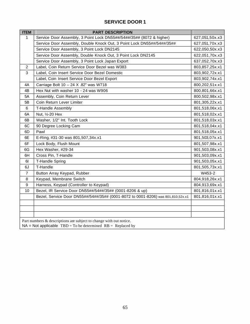
65
SERVICE DOOR 1
ITEM PART DESCRIPTION
1 Service Door Assembly, 3 Point Lock DN55##/54##/35## (8072 & higher) 627,051,50x.x3 Service Door Assembly, Double Knock Out, 3 Point Lock DN55##/54##/35## 627,051,70x.x3 Service Door Assembly, 3 Point Lock DN2145 622,050,50x.x3
Service Door Assembly, Double Knock Out, 3 Point Lock DN2145 622,051,70x.x3 Service Door Assembly, 3 Point Lock Japan Export 637,052,70x.x3
2 Label, Coin Return Service Door Bezel was W383 803,857,25x.x1 3 Label, Coin Insert Service Door Bezel Domestic 803,902,72x.x1 Label, Coin Insert Service Door Bezel Export 803,902,74x.x1
4A Carriage Bolt 10 – 24 X .82” was W718 800,202,51x.x1 4B Hex Nut with washer 10 - 24 was W906 800,801,66x.x1 5A Assembly, Coin Return Lever 800,502,98x.x1 5B Coin Return Lever Limiter 801,305,22x.x1 6 T-Handle Assembly 801,518,06x.x1
6A Nut, ½-20 Hex 801,518,02x.x1 6B Washer, 1/2” Int. Tooth Lock 801,518,03x.x1 6C 90 Degree Locking Cam 801,518,04x.x1 6D Pawl 801,518,05x.x1 6E E-Ring, #31-30 was 801,507,34x.x1 901,503,07x.x1
6F Lock Body, Flush Mount 801,507,98x.x1 6G Hex Washer, #29-34 901,503,08x.x1 6H Cross Pin, T-Handle 901,503,09x.x1 6I T-Handle Spring 901,503,05x.x1 6J T-Handle 801,505,73x.x1
7 Button Array Keypad, Rubber W453-2 8 Keypad, Membrane Switch 804,918,26x.x1 9 Harness, Keypad (Controller to Keypad) 804,913,69x.x1 10 Bezel, IR Service Door DN55##/54##/35## (0001-8206 & up) 801,816,01x.x1 Bezel, Service Door DN55##/54##/35## (0001-8072 to 0001-8206) was 801,810,52x.x1 801,816,01x.x1
Part numbers & descriptions are subject to change with out notice. NA = Not applicable TBD = To be determined RB = Replaced by
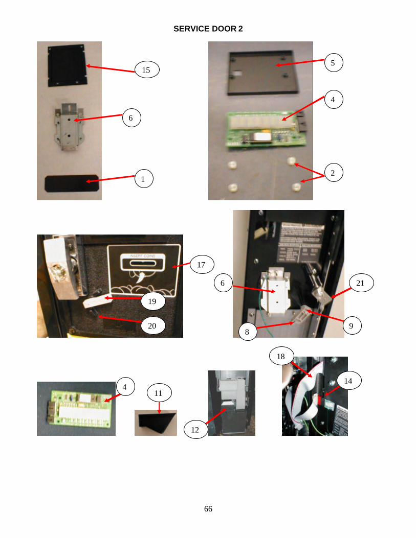
66
SERVICE DOOR 2
15
6
5
4
1 2
6
17
20 8
19
21
9
11
12
4 14
18
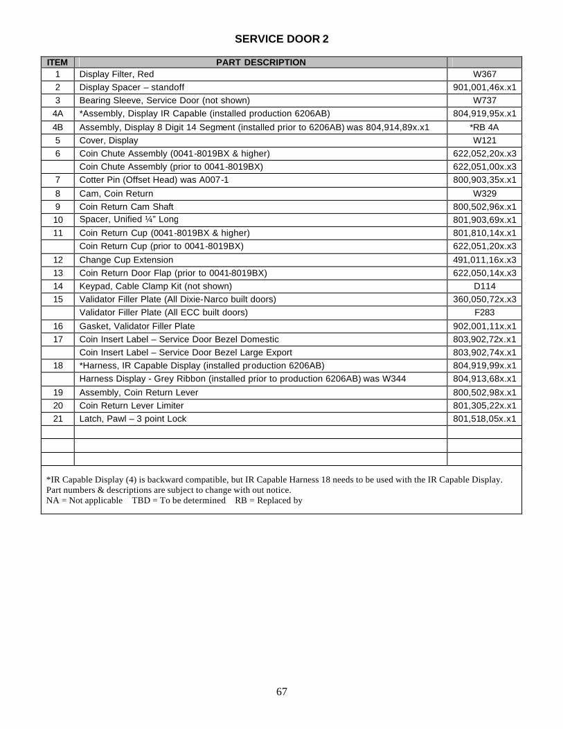
67
SERVICE DOOR 2
ITEM PART DESCRIPTION 1 Display Filter, Red W367 2 Display Spacer – standoff 901,001,46x.x1 3 Bearing Sleeve, Service Door (not shown) W737
4A *Assembly, Display IR Capable (installed production 6206AB) 804,919,95x.x1
4B Assembly, Display 8 Digit 14 Segment (installed prior to 6206AB) was 804,914,89x.x1 *RB 4A 5 Cover, Display W121 6 Coin Chute Assembly (0041-8019BX & higher) 622,052,20x.x3 Coin Chute Assembly (prior to 0041-8019BX) 622,051,00x.x3
7 Cotter Pin (Offset Head) was A007-1 800,903,35x.x1
8 Cam, Coin Return W329 9 Coin Return Cam Shaft 800,502,96x.x1 10 Spacer, Unified ¼” Long
Long 801,903,69x.x1
11 Coin Return Cup (0041-8019BX & higher) 801,810,14x.x1 Coin Return Cup (prior to 0041-8019BX) 622,051,20x.x3
12 Change Cup Extension 491,011,16x.x3 13 Coin Return Door Flap (prior to 0041-8019BX) 622,050,14x.x3 14 Keypad, Cable Clamp Kit (not shown) D114 15 Validator Filler Plate (All Dixie-Narco built doors) 360,050,72x.x3 Validator Filler Plate (All ECC built doors) F283
16 Gasket, Validator Filler Plate 902,001,11x.x1 17 Coin Insert Label – Service Door Bezel Domestic 803,902,72x.x1 Coin Insert Label – Service Door Bezel Large Export 803,902,74x.x1
18 *Harness, IR Capable Display (installed production 6206AB) 804,919,99x.x1 Harness Display - Grey Ribbon (installed prior to production 6206AB) was W344 804,913,68x.x1
19 Assembly, Coin Return Lever 800,502,98x.x1 20 Coin Return Lever Limiter 801,305,22x.x1 21 Latch, Pawl – 3 point Lock 801,518,05x.x1
*IR Capable Display (4) is backward compatible, but IR Capable Harness 18 needs to be used with the IR Capable Display. Part numbers & descriptions are subject to change with out notice. NA = Not applicable TBD = To be determined RB = Replaced by
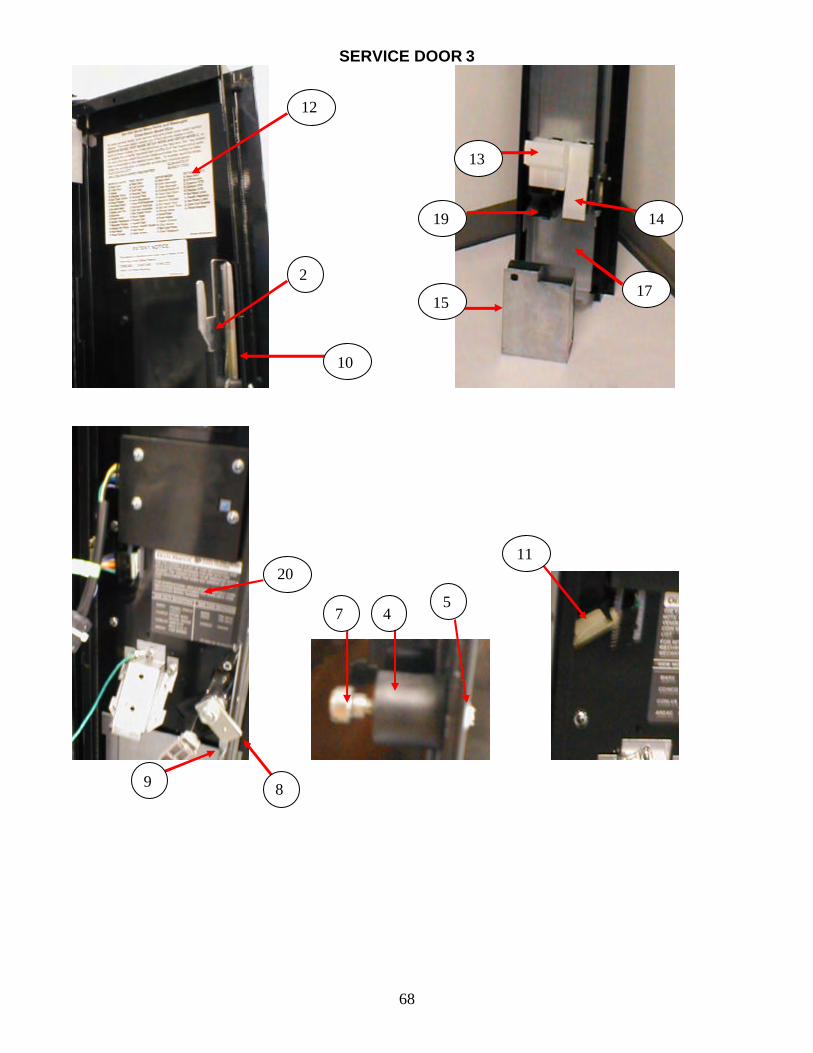
68
SERVICE DOOR 3
12
17 2
20
7 5
13
19 14
15
11
4
10
9 8
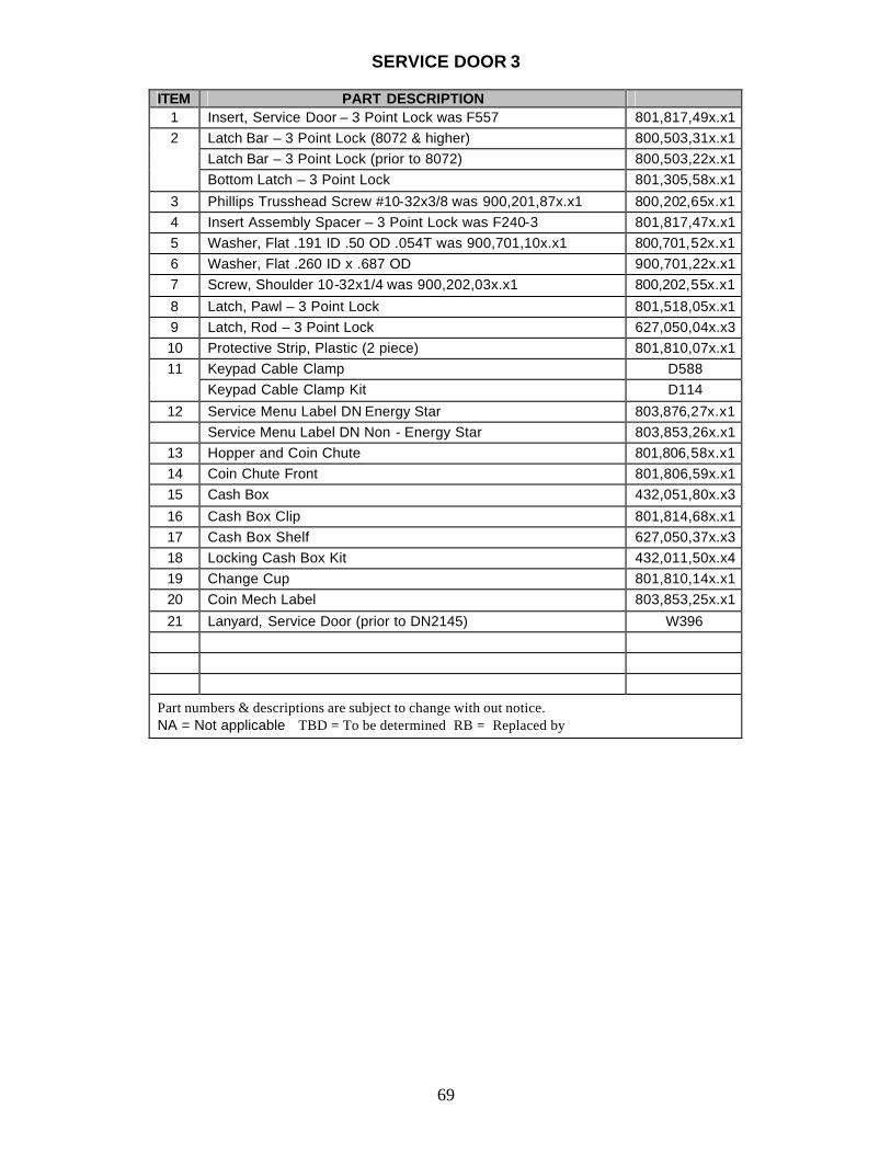
69
SERVICE DOOR 3
ITEM PART DESCRIPTION 1 Insert, Service Door – 3 Point Lock was F557 801,817,49x.x1 2 Latch Bar – 3 Point Lock (8072 & higher) 800,503,31x.x1 Latch Bar – 3 Point Lock (prior to 8072) 800,503,22x.x1 Bottom Latch – 3 Point Lock 801,305,58x.x1
3 Phillips Trusshead Screw #10-32x3/8 was 900,201,87x.x1 800,202,65x.x1 4 Insert Assembly Spacer – 3 Point Lock was F240-3 801,817,47x.x1 5 Washer, Flat .191 ID .50 OD .054T was 900,701,10x.x1 800,701,52x.x1 6 Washer, Flat .260 ID x .687 OD 900,701,22x.x1 7 Screw, Shoulder 10-32x1/4 was 900,202,03x.x1 800,202,55x.x1
8 Latch, Pawl – 3 Point Lock 801,518,05x.x1 9 Latch, Rod – 3 Point Lock 627,050,04x.x3 10 Protective Strip, Plastic (2 piece) 801,810,07x.x1 11 Keypad Cable Clamp D588 Keypad Cable Clamp Kit D114
12 Service Menu Label DN Energy Star 803,876,27x.x1 Service Menu Label DN Non - Energy Star 803,853,26x.x1
13 Hopper and Coin Chute 801,806,58x.x1 14 Coin Chute Front 801,806,59x.x1 15 Cash Box 432,051,80x.x3
16 Cash Box Clip 801,814,68x.x1 17 Cash Box Shelf 627,050,37x.x3 18 Locking Cash Box Kit 432,011,50x.x4 19 Change Cup 801,810,14x.x1 20 Coin Mech Label 803,853,25x.x1
21 Lanyard, Service Door (prior to DN2145) W396
Part numbers & descriptions are subject to change with out notice. NA = Not applicable TBD = To be determined RB = Replaced by
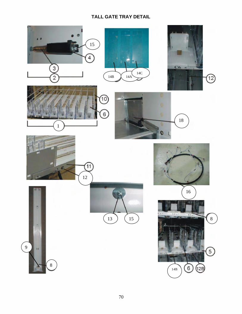
70
TALL GATE TRAY DETAIL
1
8
9
8 13 15
15
14A 14C
14B
18
16
14B
12
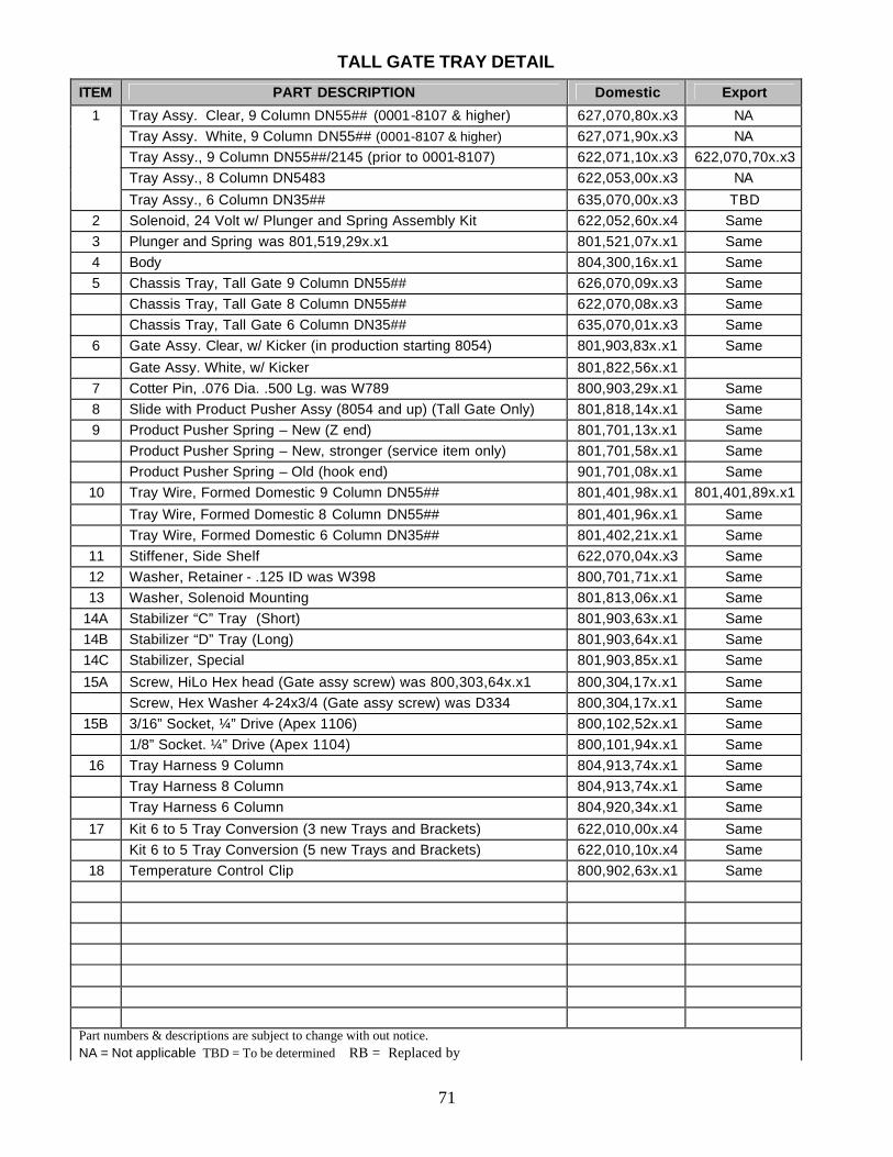
71
TALL GATE TRAY DETAIL
ITEM PART DESCRIPTION Domestic Export
1 Tray Assy. Clear, 9 Column DN55## (0001-8107 & higher) 627,070,80x.x3 NA Tray Assy. White, 9 Column DN55## (0001-8107 & higher) 627,071,90x.x3 NA Tray Assy., 9 Column DN55##/2145 (prior to 0001-8107) 622,071,10x.x3 622,070,70x.x3 Tray Assy., 8 Column DN5483 622,053,00x.x3 NA
Tray Assy., 6 Column DN35## 635,070,00x.x3 TBD 2 Solenoid, 24 Volt w/ Plunger and Spring Assembly Kit 622,052,60x.x4 Same 3 Plunger and Spring was 801,519,29x.x1 801,521,07x.x1 Same 4 Body 804,300,16x.x1 Same 5 Chassis Tray, Tall Gate 9 Column DN55## 626,070,09x.x3 Same Chassis Tray, Tall Gate 8 Column DN55## 622,070,08x.x3 Same Chassis Tray, Tall Gate 6 Column DN35## 635,070,01x.x3 Same
6 Gate Assy. Clear, w/ Kicker (in production starting 8054) 801,903,83x.x1 Same
Gate Assy. White, w/ Kicker 801,822,56x.x1 7 Cotter Pin, .076 Dia. .500 Lg. was W789 800,903,29x.x1 Same 8 Slide with Product Pusher Assy (8054 and up) (Tall Gate Only) 801,818,14x.x1 Same 9 Product Pusher Spring – New (Z end) 801,701,13x.x1 Same Product Pusher Spring – New, stronger (service item only) 801,701,58x.x1 Same Product Pusher Spring – Old (hook end) 901,701,08x.x1 Same
10 Tray Wire, Formed Domestic 9 Column DN55## 801,401,98x.x1 801,401,89x.x1
Tray Wire, Formed Domestic 8 Column DN55## 801,401,96x.x1 Same Tray Wire, Formed Domestic 6 Column DN35## 801,402,21x.x1 Same
11 Stiffener, Side Shelf 622,070,04x.x3 Same 12 Washer, Retainer - .125 ID was W398 800,701,71x.x1 Same 13 Washer, Solenoid Mounting 801,813,06x.x1 Same
14A Stabilizer “C” Tray (Short) 801,903,63x.x1 Same 14B Stabilizer “D” Tray (Long) 801,903,64x.x1 Same 14C Stabilizer, Special 801,903,85x.x1 Same
15A Screw, HiLo Hex head (Gate assy screw) was 800,303,64x.x1 800,304,17x.x1 Same Screw, Hex Washer 4-24x3/4 (Gate assy screw) was D334 800,304,17x.x1 Same
15B 3/16” Socket, ¼” Drive (Apex 1106) 800,102,52x.x1 Same 1/8” Socket. ¼” Drive (Apex 1104) 800,101,94x.x1 Same
16 Tray Harness 9 Column 804,913,74x.x1 Same Tray Harness 8 Column 804,913,74x.x1 Same Tray Harness 6 Column 804,920,34x.x1 Same
17 Kit 6 to 5 Tray Conversion (3 new Trays and Brackets) 622,010,00x.x4 Same Kit 6 to 5 Tray Conversion (5 new Trays and Brackets) 622,010,10x.x4 Same
18 Temperature Control Clip 800,902,63x.x1 Same
Part numbers & descriptions are subject to change with out notice. NA = Not applicable TBD = To be determined RB = Replaced by
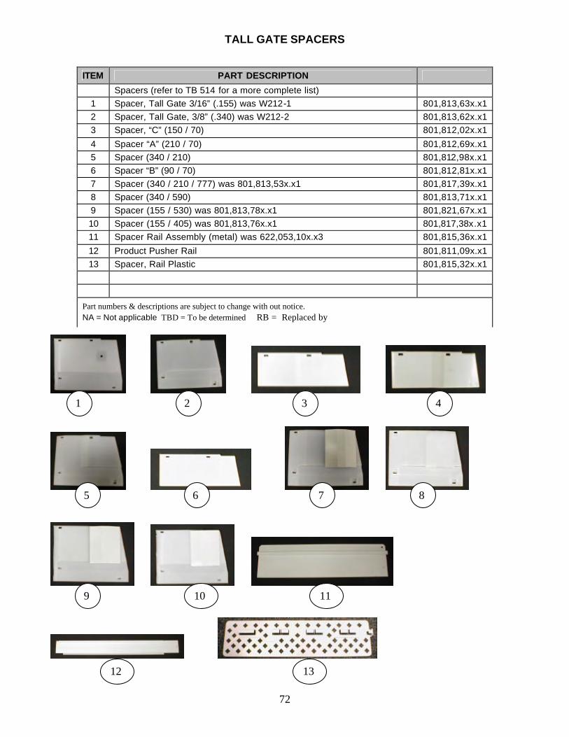
72
TALL GATE SPACERS
ITEM PART DESCRIPTION
Spacers (refer to TB 514 for a more complete list) 1 Spacer, Tall Gate 3/16” (.155) was W212-1 801,813,63x.x1 2 Spacer, Tall Gate, 3/8” (.340) was W212-2 801,813,62x.x1 3 Spacer, “C” (150 / 70) 801,812,02x.x1
4 Spacer “A” (210 / 70) 801,812,69x.x1 5 Spacer (340 / 210) 801,812,98x.x1 6 Spacer “B” (90 / 70) 801,812,81x.x1 7 Spacer (340 / 210 / 777) was 801,813,53x.x1 801,817,39x.x1 8 Spacer (340 / 590) 801,813,71x.x1 9 Spacer (155 / 530) was 801,813,78x.x1 801,821,67x.x1 10 Spacer (155 / 405) was 801,813,76x.x1 801,817,38x.x1 11 Spacer Rail Assembly (metal) was 622,053,10x.x3 801,815,36x.x1
12 Product Pusher Rail 801,811,09x.x1 13 Spacer, Rail Plastic 801,815,32x.x1
Part numbers & descriptions are subject to change with out notice. NA = Not applicable TBD = To be determined RB = Replaced by
1 2 3 4
8 7 6 5
9 10 11
12 13
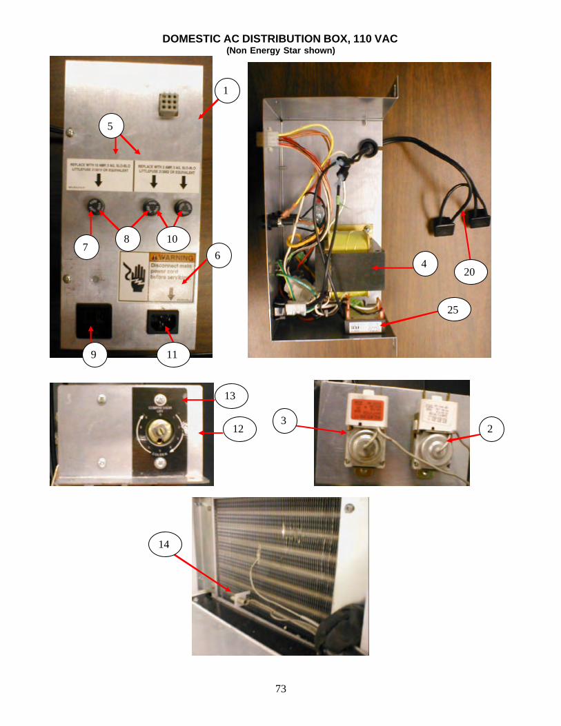
73
DOMESTIC AC DISTRIBUTION BOX, 110 VAC (Non Energy Star shown)
4 7
12
1
3 2
6
9 11
13
14
25
5
8 10
20
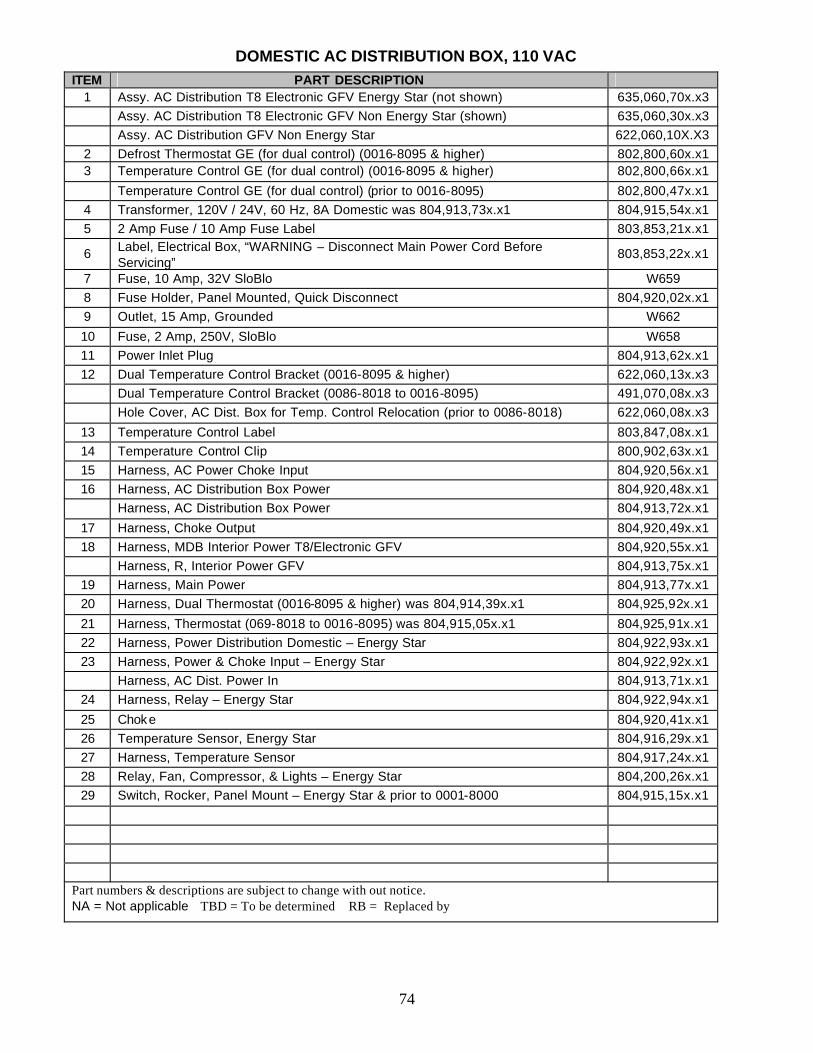
74
DOMESTIC AC DISTRIBUTION BOX, 110 VAC ITEM PART DESCRIPTION
1 Assy. AC Distribution T8 Electronic GFV Energy Star (not shown) 635,060,70x.x3 Assy. AC Distribution T8 Electronic GFV Non Energy Star (shown) 635,060,30x.x3 Assy. AC Distribution GFV Non Energy Star 622,060,10X.X3
2 Defrost Thermostat GE (for dual control) (0016-8095 & higher) 802,800,60x.x1 3 Temperature Control GE (for dual control) (0016-8095 & higher) 802,800,66x.x1
Temperature Control GE (for dual control) (prior to 0016-8095) 802,800,47x.x1 4 Transformer, 120V / 24V, 60 Hz, 8A Domestic was 804,913,73x.x1 804,915,54x.x1 5 2 Amp Fuse / 10 Amp Fuse Label 803,853,21x.x1
6 Label, Electrical Box, “WARNING – Disconnect Main Power Cord Before Servicing”
803,853,22x.x1
7 Fuse, 10 Amp, 32V SloBlo W659 8 Fuse Holder, Panel Mounted, Quick Disconnect 804,920,02x.x1 9 Outlet, 15 Amp, Grounded W662
10 Fuse, 2 Amp, 250V, SloBlo W658 11 Power Inlet Plug 804,913,62x.x1 12 Dual Temperature Control Bracket (0016-8095 & higher) 622,060,13x.x3 Dual Temperature Control Bracket (0086-8018 to 0016-8095) 491,070,08x.x3 Hole Cover, AC Dist. Box for Temp. Control Relocation (prior to 0086-8018) 622,060,08x.x3
13 Temperature Control Label 803,847,08x.x1 14 Temperature Control Clip 800,902,63x.x1 15 Harness, AC Power Choke Input 804,920,56x.x1 16 Harness, AC Distribution Box Power 804,920,48x.x1 Harness, AC Distribution Box Power 804,913,72x.x1
17 Harness, Choke Output 804,920,49x.x1 18 Harness, MDB Interior Power T8/Electronic GFV 804,920,55x.x1 Harness, R, Interior Power GFV 804,913,75x.x1
19 Harness, Main Power 804,913,77x.x1 20 Harness, Dual Thermostat (0016-8095 & higher) was 804,914,39x.x1 804,925,92x.x1
21 Harness, Thermostat (069-8018 to 0016-8095) was 804,915,05x.x1 804,925,91x.x1 22 Harness, Power Distribution Domestic – Energy Star 804,922,93x.x1 23 Harness, Power & Choke Input – Energy Star 804,922,92x.x1 Harness, AC Dist. Power In 804,913,71x.x1
24 Harness, Relay – Energy Star 804,922,94x.x1
25 Choke 804,920,41x.x1 26 Temperature Sensor, Energy Star 804,916,29x.x1 27 Harness, Temperature Sensor 804,917,24x.x1 28 Relay, Fan, Compressor, & Lights – Energy Star 804,200,26x.x1 29 Switch, Rocker, Panel Mount – Energy Star & prior to 0001-8000 804,915,15x.x1
Part numbers & descriptions are subject to change with out notice. NA = Not applicable TBD = To be determined RB = Replaced by
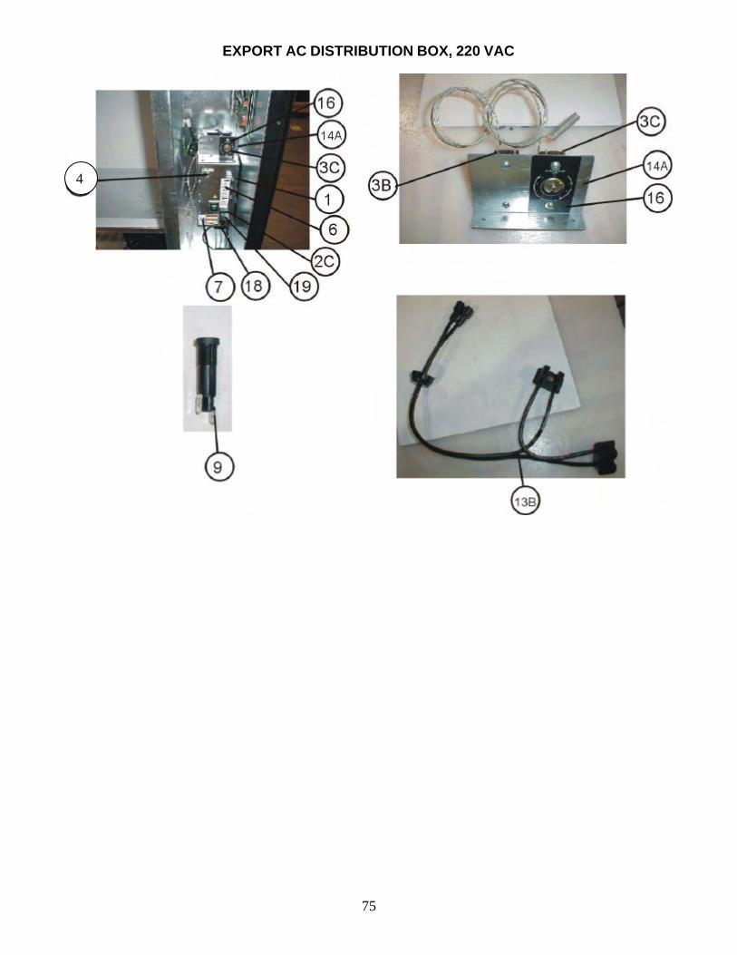
75
EXPORT AC DISTRIBUTION BOX, 220 VAC
4
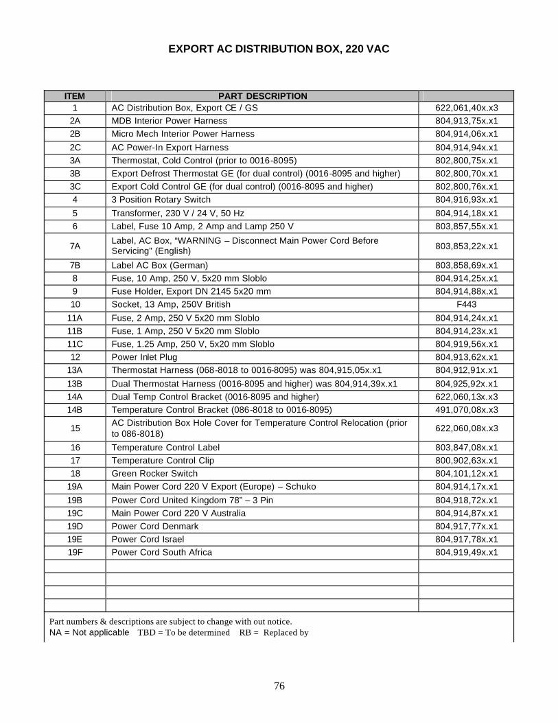
76
EXPORT AC DISTRIBUTION BOX, 220 VAC
ITEM PART DESCRIPTION 1 AC Distribution Box, Export CE / GS 622,061,40x.x3
2A MDB Interior Power Harness 804,913,75x.x1 2B Micro Mech Interior Power Harness 804,914,06x.x1
2C AC Power-In Export Harness 804,914,94x.x1 3A Thermostat, Cold Control (prior to 0016-8095) 802,800,75x.x1 3B Export Defrost Thermostat GE (for dual control) (0016-8095 and higher) 802,800,70x.x1 3C Export Cold Control GE (for dual control) (0016-8095 and higher) 802,800,76x.x1 4 3 Position Rotary Switch 804,916,93x.x1
5 Transformer, 230 V / 24 V, 50 Hz 804,914,18x.x1 6 Label, Fuse 10 Amp, 2 Amp and Lamp 250 V 803,857,55x.x1
7A Label, AC Box, “WARNING – Disconnect Main Power Cord Before Servicing” (English) 803,853,22x.x1
7B Label AC Box (German) 803,858,69x.x1 8 Fuse, 10 Amp, 250 V, 5x20 mm Sloblo 804,914,25x.x1 9 Fuse Holder, Export DN 2145 5x20 mm 804,914,88x.x1 10 Socket, 13 Amp, 250V British F443
11A Fuse, 2 Amp, 250 V 5x20 mm Sloblo 804,914,24x.x1 11B Fuse, 1 Amp, 250 V 5x20 mm Sloblo 804,914,23x.x1 11C Fuse, 1.25 Amp, 250 V, 5x20 mm Sloblo 804,919,56x.x1 12 Power Inlet Plug 804,913,62x.x1
13A Thermostat Harness (068-8018 to 0016-8095) was 804,915,05x.x1 804,912,91x.x1
13B Dual Thermostat Harness (0016-8095 and higher) was 804,914,39x.x1 804,925,92x.x1 14A Dual Temp Control Bracket (0016-8095 and higher) 622,060,13x.x3 14B Temperature Control Bracket (086-8018 to 0016-8095) 491,070,08x.x3
15 AC Distribution Box Hole Cover for Temperature Control Relocation (prior to 086-8018)
622,060,08x.x3
16 Temperature Control Label 803,847,08x.x1 17 Temperature Control Clip 800,902,63x.x1 18 Green Rocker Switch 804,101,12x.x1
19A Main Power Cord 220 V Export (Europe) – Schuko 804,914,17x.x1
19B Power Cord United Kingdom 78” – 3 Pin 804,918,72x.x1 19C Main Power Cord 220 V Australia 804,914,87x.x1 19D Power Cord Denmark 804,917,77x.x1 19E Power Cord Israel 804,917,78x.x1 19F Power Cord South Africa 804,919,49x.x1
Part numbers & descriptions are subject to change with out notice. NA = Not applicable TBD = To be determined RB = Replaced by
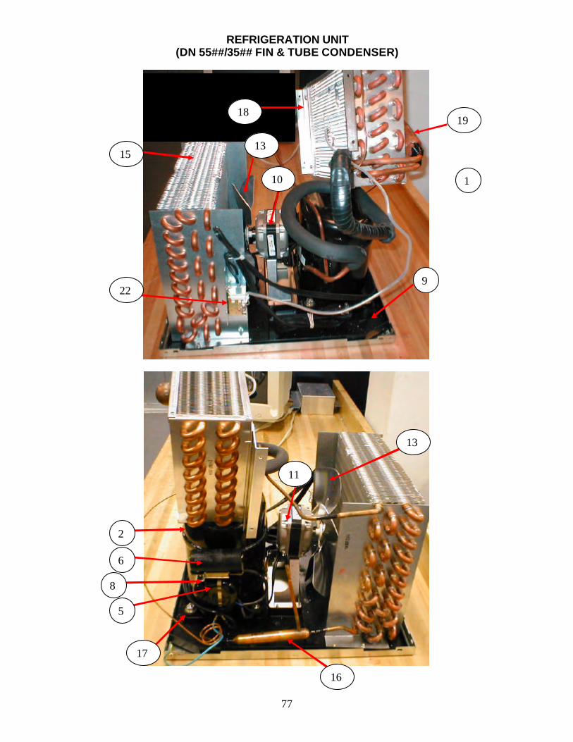
77
REFRIGERATION UNIT (DN 55##/35## FIN & TUBE CONDENSER)
19
11
10
13
18
9
1
22
15
13
16
6
5
2
8
17
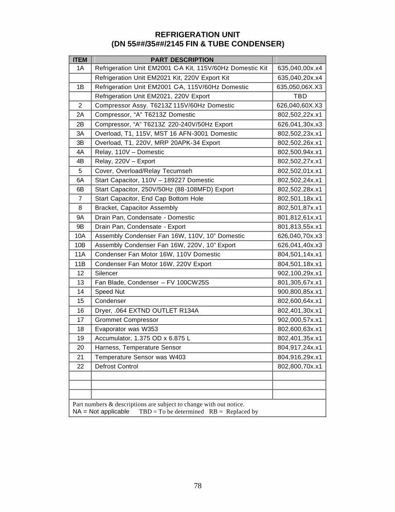
78
REFRIGERATION UNIT
(DN 55##/35##/2145 FIN & TUBE CONDENSER)
ITEM PART DESCRIPTION 1A Refrigeration Unit EM2001 C-A Kit, 115V/60Hz Domestic Kit 635,040,00x.x4
Refrigeration Unit EM2021 Kit, 220V Export Kit 635,040,20x.x4 1B Refrigeration Unit EM2001 C-A, 115V/60Hz Domestic 635,050,06X.X3
Refrigeration Unit EM2021, 220V Export TBD 2 Compressor Assy. T6213Z 115V/60Hz Domestic 626,040,60X.X3
2A Compressor, “A” T6213Z Domestic 802,502,22x.x1
2B Compressor, “A” T6213Z 220-240V/50Hz Export 626,041,30x.x3 3A Overload, T1, 115V, MST 16 AFN-3001 Domestic 802,502,23x.x1 3B Overload, T1, 220V, MRP 20APK-34 Export 802,502,26x.x1 4A Relay, 110V – Domestic 802,500,94x.x1 4B Relay, 220V – Export 802,502,27x.x1
5 Cover, Overload/Relay Tecumseh 802,502,01x.x1 6A Start Capacitor, 110V – 189227 Domestic 802,502,24x.x1 6B Start Capacitor, 250V/50Hz (88-108MFD) Export 802,502,28x.x1 7 Start Capacitor, End Cap Bottom Hole 802,501,18x.x1 8 Bracket, Capacitor Assembly 802,501,87x.x1
9A Drain Pan, Condensate - Domestic 801,812,61x.x1 9B Drain Pan, Condensate - Export 801,813,55x.x1
10A Assembly Condenser Fan 16W, 110V, 10” Domestic 626,040,70x.x3 10B Assembly Condenser Fan 16W, 220V, 10” Export 626,041,40x.x3 11A Condenser Fan Motor 16W, 110V Domestic 804,501,14x.x1
11B Condenser Fan Motor 16W, 220V Export 804,501,18x.x1 12 Silencer 902,100,29x.x1 13 Fan Blade, Condenser – FV 100CW25S 801,305,67x.x1 14 Speed Nut 900,800,85x.x1 15 Condenser 802,600,64x.x1
16 Dryer, .064 EXTND OUTLET R134A 802,401,30x.x1 17 Grommet Compressor 902,000,57x.x1 18 Evaporator was W353 802,600,63x.x1 19 Accumulator, 1.375 OD x 6.875 L 802,401,35x.x1 20 Harness, Temperature Sensor 804,917,24x.x1
21 Temperature Sensor was W403 804,916,29x.x1 22 Defrost Control 802,800,70x.x1
Part numbers & descriptions are subject to change with out notice. NA = Not applicable TBD = To be determined RB = Replaced by
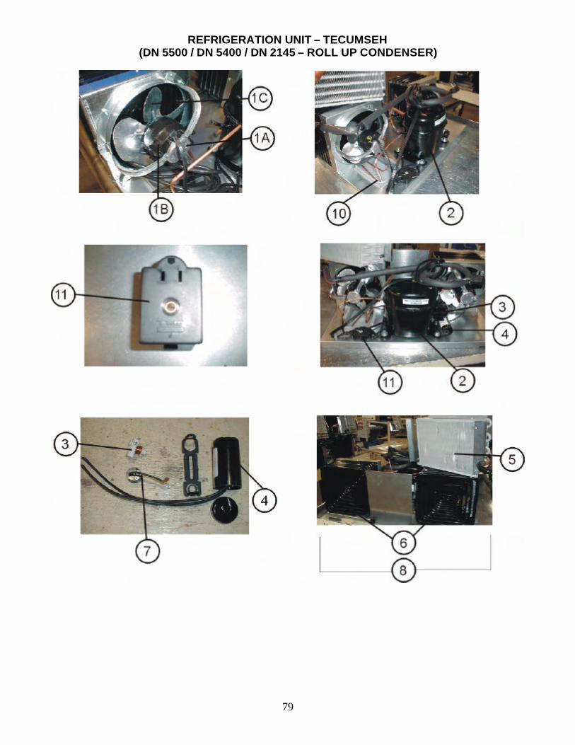
79
REFRIGERATION UNIT – TECUMSEH (DN 5500 / DN 5400 / DN 2145 – ROLL UP CONDENSER)
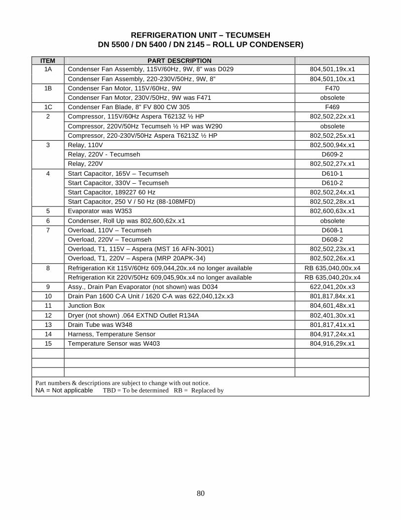
80
REFRIGERATION UNIT – TECUMSEH
DN 5500 / DN 5400 / DN 2145 – ROLL UP CONDENSER)
ITEM PART DESCRIPTION 1A Condenser Fan Assembly, 115V/60Hz, 9W, 8” was D029 804,501,19x.x1
Condenser Fan Assembly, 220-230V/50Hz, 9W, 8” 804,501,10x.x1 1B Condenser Fan Motor, 115V/60Hz, 9W F470
Condenser Fan Motor, 230V/50Hz, 9W was F471 obsolete 1C Condenser Fan Blade, 8” FV 800 CW 305 F469 2 Compressor, 115V/60Hz Aspera T6213Z ½ HP 802,502,22x.x1
Compressor, 220V/50Hz Tecumseh ½ HP was W290 obsolete Compressor, 220-230V/50Hz Aspera T6213Z ½ HP 802,502,25x.x1
3 Relay, 110V 802,500,94x.x1 Relay, 220V - Tecumseh D609-2 Relay, 220V 802,502,27x.x1
4 Start Capacitor, 165V – Tecumseh D610-1 Start Capacitor, 330V – Tecumseh D610-2 Start Capacitor, 189227 60 Hz 802,502,24x.x1 Start Capacitor, 250 V / 50 Hz (88-108MFD) 802,502,28x.x1
5 Evaporator was W353 802,600,63x.x1
6 Condenser, Roll Up was 802,600,62x.x1 obsolete 7 Overload, 110V – Tecumseh D608-1 Overload, 220V – Tecumseh D608-2 Overload, T1, 115V – Aspera (MST 16 AFN-3001) 802,502,23x.x1 Overload, T1, 220V – Aspera (MRP 20APK-34) 802,502,26x.x1
8 Refrigeration Kit 115V/60Hz 609,044,20x.x4 no longer available RB 635,040,00x.x4 Refrigeration Kit 220V/50Hz 609,045,90x.x4 no longer available RB 635,040,20x.x4
9 Assy., Drain Pan Evaporator (not shown) was D034 622,041,20x.x3 10 Drain Pan 1600 C-A Unit / 1620 C-A was 622,040,12x.x3 801,817,84x.x1 11 Junction Box 804,601,48x.x1
12 Dryer (not shown) .064 EXTND Outlet R134A 802,401,30x.x1 13 Drain Tube was W348 801,817,41x.x1 14 Harness, Temperature Sensor 804,917,24x.x1 15 Temperature Sensor was W403 804,916,29x.x1
Part numbers & descriptions are subject to change with out notice. NA = Not applicable TBD = To be determined RB = Replaced by
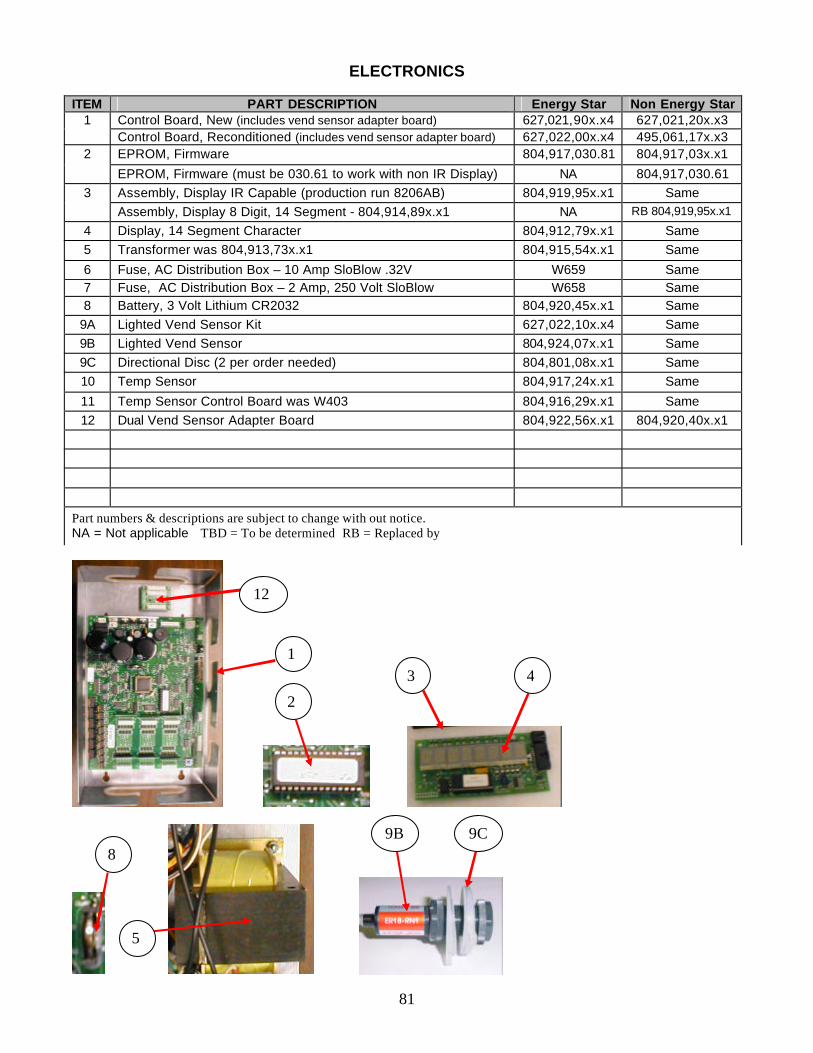
81
ELECTRONICS
ITEM PART DESCRIPTION Energy Star Non Energy Star 1 Control Board, New (includes vend sensor adapter board) 627,021,90x.x4 627,021,20x.x3 Control Board, Reconditioned (includes vend sensor adapter board) 627,022,00x.x4 495,061,17x.x3
2 EPROM, Firmware 804,917,030.81 804,917,03x.x1
EPROM, Firmware (must be 030.61 to work with non IR Display) NA 804,917,030.61 3 Assembly, Display IR Capable (production run 8206AB) 804,919,95x.x1 Same Assembly, Display 8 Digit, 14 Segment - 804,914,89x.x1 NA RB 804,919,95x.x1
4 Display, 14 Segment Character 804,912,79x.x1 Same 5 Transformer was 804,913,73x.x1 804,915,54x.x1 Same
6 Fuse, AC Distribution Box – 10 Amp SloBlow .32V W659 Same 7 Fuse, AC Distribution Box – 2 Amp, 250 Volt SloBlow W658 Same 8 Battery, 3 Volt Lithium CR2032 804,920,45x.x1 Same
9A Lighted Vend Sensor Kit 627,022,10x.x4 Same 9B Lighted Vend Sensor 804,924,07x.x1 Same 9C Directional Disc (2 per order needed) 804,801,08x.x1 Same 10 Temp Sensor 804,917,24x.x1 Same
11 Temp Sensor Control Board was W403 804,916,29x.x1 Same 12 Dual Vend Sensor Adapter Board 804,922,56x.x1 804,920,40x.x1
Part numbers & descriptions are subject to change with out notice. NA = Not applicable TBD = To be determined RB = Replaced by
8
1
9C
5
9B
3
2
12
4
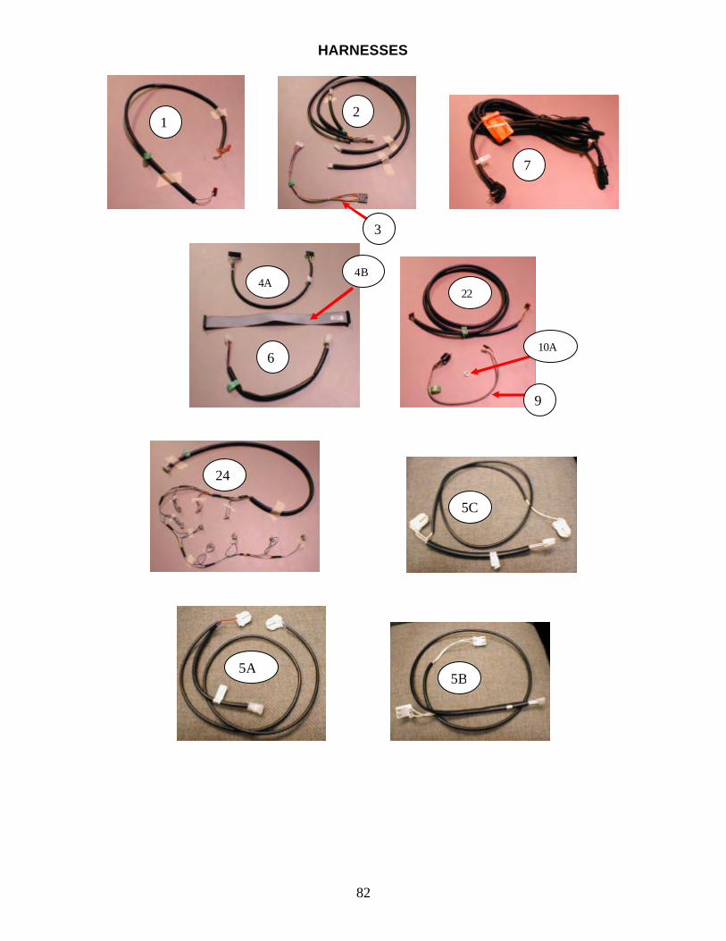
82
HARNESSES
1 2
3
7
4A
6
4B
24
22
5A 5B
5C
9
10A
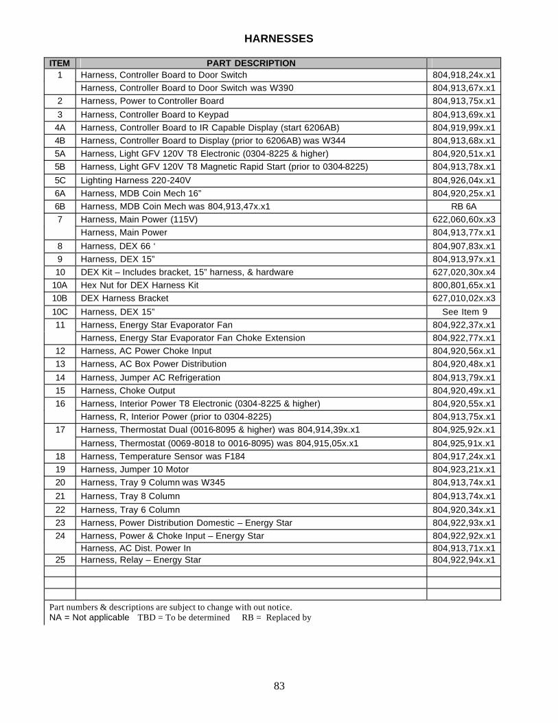
83
HARNESSES
ITEM PART DESCRIPTION 1 Harness, Controller Board to Door Switch 804,918,24x.x1 Harness, Controller Board to Door Switch was W390 804,913,67x.x1
2 Harness, Power to Controller Board 804,913,75x.x1
3 Harness, Controller Board to Keypad 804,913,69x.x1 4A Harness, Controller Board to IR Capable Display (start 6206AB) 804,919,99x.x1 4B Harness, Controller Board to Display (prior to 6206AB) was W344 804,913,68x.x1 5A Harness, Light GFV 120V T8 Electronic (0304-8225 & higher) 804,920,51x.x1 5B Harness, Light GFV 120V T8 Magnetic Rapid Start (prior to 0304-8225) 804,913,78x.x1
5C Lighting Harness 220-240V 804,926,04x.x1 6A Harness, MDB Coin Mech 16” 804,920,25x.x1 6B Harness, MDB Coin Mech was 804,913,47x.x1 RB 6A 7 Harness, Main Power (115V) 622,060,60x.x3 Harness, Main Power 804,913,77x.x1
8 Harness, DEX 66 ‘ 804,907,83x.x1 9 Harness, DEX 15” 804,913,97x.x1 10 DEX Kit – Includes bracket, 15” harness, & hardware 627,020,30x.x4
10A Hex Nut for DEX Harness Kit 800,801,65x.x1 10B DEX Harness Bracket 627,010,02x.x3
10C Harness, DEX 15” See Item 9 11 Harness, Energy Star Evaporator Fan 804,922,37x.x1 Harness, Energy Star Evaporator Fan Choke Extension 804,922,77x.x1
12 Harness, AC Power Choke Input 804,920,56x.x1 13 Harness, AC Box Power Distribution 804,920,48x.x1
14 Harness, Jumper AC Refrigeration 804,913,79x.x1 15 Harness, Choke Output 804,920,49x.x1 16 Harness, Interior Power T8 Electronic (0304-8225 & higher) 804,920,55x.x1 Harness, R, Interior Power (prior to 0304-8225) 804,913,75x.x1
17 Harness, Thermostat Dual (0016-8095 & higher) was 804,914,39x.x1 804,925,92x.x1
Harness, Thermostat (0069-8018 to 0016-8095) was 804,915,05x.x1 804,925,91x.x1 18 Harness, Temperature Sensor was F184 804,917,24x.x1 19 Harness, Jumper 10 Motor 804,923,21x.x1 20 Harness, Tray 9 Column was W345 804,913,74x.x1
21 Harness, Tray 8 Column 804,913,74x.x1
22 Harness, Tray 6 Column 804,920,34x.x1 23 Harness, Power Distribution Domestic – Energy Star 804,922,93x.x1 24 Harness, Power & Choke Input – Energy Star 804,922,92x.x1 Harness, AC Dist. Power In 804,913,71x.x1
25 Harness, Relay – Energy Star 804,922,94x.x1
Part numbers & descriptions are subject to change with out notice. NA = Not applicable TBD = To be determined RB = Replaced by
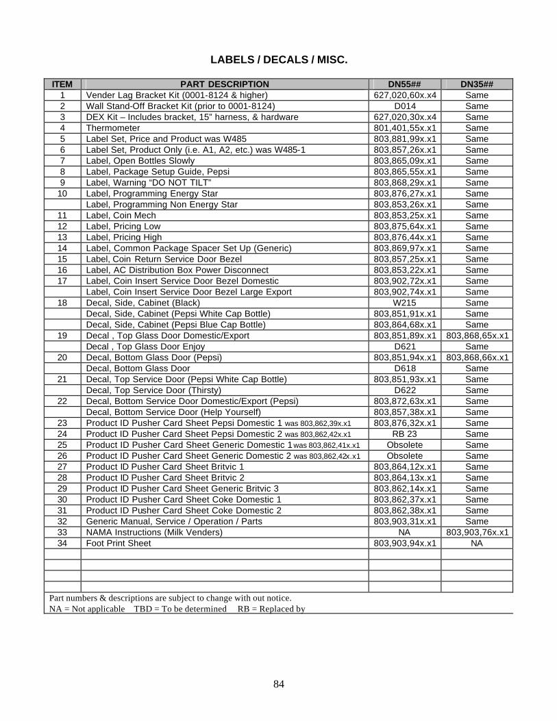
84
LABELS / DECALS / MISC. ITEM PART DESCRIPTION DN55## DN35##
1 Vender Lag Bracket Kit (0001-8124 & higher) 627,020,60x.x4 Same 2 Wall Stand-Off Bracket Kit (prior to 0001-8124) D014 Same 3 DEX Kit – Includes bracket, 15” harness, & hardware 627,020,30x.x4 Same 4 Thermometer 801,401,55x.x1 Same 5 Label Set, Price and Product was W485 803,881,99x.x1 Same 6 Label Set, Product Only (i.e. A1, A2, etc.) was W485-1 803,857,26x.x1 Same 7 Label, Open Bottles Slowly 803,865,09x.x1 Same 8 Label, Package Setup Guide, Pepsi 803,865,55x.x1 Same 9 Label, Warning “DO NOT TILT” 803,868,29x.x1 Same
10 Label, Programming Energy Star 803,876,27x.x1 Same Label, Programming Non Energy Star 803,853,26x.x1 Same
11 Label, Coin Mech 803,853,25x.x1 Same 12 Label, Pricing Low 803,875,64x.x1 Same 13 Label, Pricing High 803,876,44x.x1 Same 14 Label, Common Package Spacer Set Up (Generic) 803,869,97x.x1 Same 15 Label, Coin Return Service Door Bezel 803,857,25x.x1 Same 16 Label, AC Distribution Box Power Disconnect 803,853,22x.x1 Same 17 Label, Coin Insert Service Door Bezel Domestic 803,902,72x.x1 Same Label, Coin Insert Service Door Bezel Large Export 803,902,74x.x1 Same
18 Decal, Side, Cabinet (Black) W215 Same Decal, Side, Cabinet (Pepsi White Cap Bottle) 803,851,91x.x1 Same Decal, Side, Cabinet (Pepsi Blue Cap Bottle) 803,864,68x.x1 Same
19 Decal , Top Glass Door Domestic/Export 803,851,89x.x1 803,868,65x.x1 Decal , Top Glass Door Enjoy D621 Same
20 Decal, Bottom Glass Door (Pepsi) 803,851,94x.x1 803,868,66x.x1 Decal, Bottom Glass Door D618 Same
21 Decal, Top Service Door (Pepsi White Cap Bottle) 803,851,93x.x1 Same Decal, Top Service Door (Thirsty) D622 Same
22 Decal, Bottom Service Door Domestic/Export (Pepsi) 803,872,63x.x1 Same Decal, Bottom Service Door (Help Yourself) 803,857,38x.x1 Same
23 Product ID Pusher Card Sheet Pepsi Domestic 1 was 803,862,39x.x1 803,876,32x.x1 Same 24 Product ID Pusher Card Sheet Pepsi Domestic 2 was 803,862,42x.x1 RB 23 Same 25 Product ID Pusher Card Sheet Generic Domestic 1 was 803,862,41x.x1 Obsolete Same 26 Product ID Pusher Card Sheet Generic Domestic 2 was 803,862,42x.x1 Obsolete Same 27 Product ID Pusher Card Sheet Britvic 1 803,864,12x.x1 Same 28 Product ID Pusher Card Sheet Britvic 2 803,864,13x.x1 Same 29 Product ID Pusher Card Sheet Generic Britvic 3 803,862,14x.x1 Same 30 Product ID Pusher Card Sheet Coke Domestic 1 803,862,37x.x1 Same 31 Product ID Pusher Card Sheet Coke Domestic 2 803,862,38x.x1 Same 32 Generic Manual, Service / Operation / Parts 803,903,31x.x1 Same 33 NAMA Instructions (Milk Venders) NA 803,903,76x.x1 34 Foot Print Sheet 803,903,94x.x1 NA
Part numbers & descriptions are subject to change with out notice. NA = Not applicable TBD = To be determined RB = Replaced by
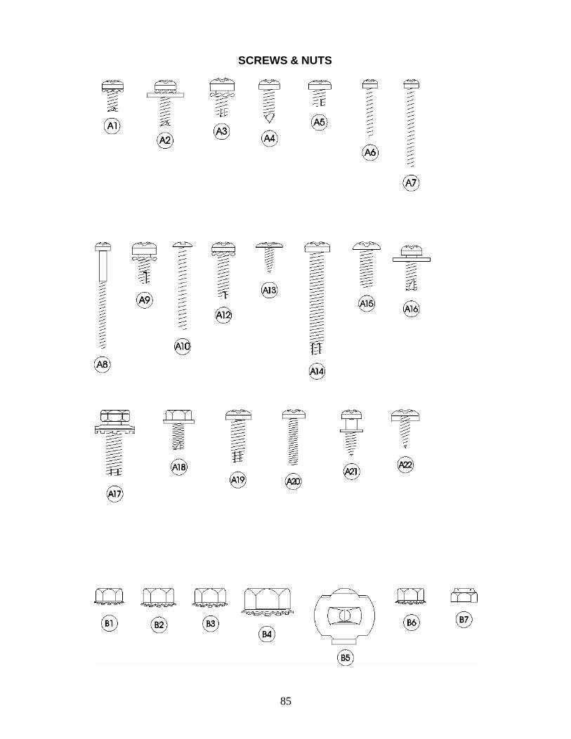
85
SCREWS & NUTS
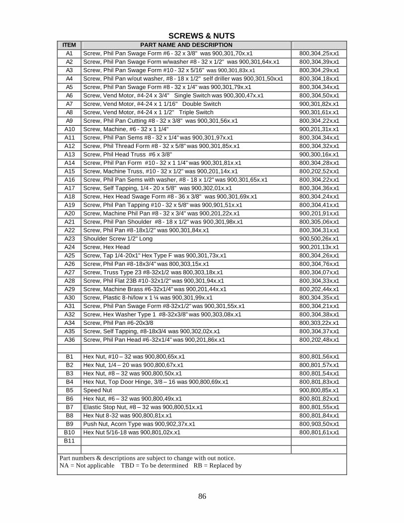
86
SCREWS & NUTS ITEM PART NAME AND DESCRIPTION
A1 Screw, Phil Pan Swage Form #6 - 32 x 3/8" was 900,301,70x.x1 800,304,25x.x1 A2 Screw, Phil Pan Swage Form w/washer #8 - 32 x 1/2" was 900,301,64x.x1 800,304,39x.x1 A3 Screw, Phil Pan Swage Form #10 - 32 x 5/16" was 900,301,83x.x1 800,304,29x.x1 A4 Screw, Phil Pan w/out washer, #8 - 18 x 1/2" self driller was 900,301,50x.x1 800,304,18x.x1 A5 Screw, Phil Pan Swage Form #8 - 32 x 1/4" was 900,301,79x.x1 800,304,34x.x1 A6 Screw, Vend Motor, #4-24 x 3/4" Single Switch was 900,300,47x.x1 800,304,50x.x1 A7 Screw, Vend Motor, #4-24 x 1 1/16" Double Switch 900,301,82x.x1 A8 Screw, Vend Motor, #4-24 x 1 1/2" Triple Switch 900,301,61x.x1 A9 Screw, Phil Pan Cutting #8 - 32 x 3/8" was 900,301,56x.x1 800,304,22x.x1 A10 Screw, Machine, #6 - 32 x 1 1/4" 900,201,31x.x1 A11 Screw, Phil Pan Sems #8 - 32 x 1/4" was 900,301,97x.x1 800,304,34x.x1 A12 Screw, Phil Thread Form #8 - 32 x 5/8" was 900,301,85x.x1 800,304,32x.x1 A13 Screw, Phil Head Truss #6 x 3/8" 900,300,16x.x1 A14 Screw, Phil Pan Form #10 - 32 x 1 1/4" was 900,301,81x.x1 800,304,28x.x1 A15 Screw, Machine Truss, #10 - 32 x 1/2" was 900,201,14x.x1 800,202,52x.x1 A16 Screw, Phil Pan Sems with washer, #8 - 18 x 1/2" was 900,301,65x.x1 800,304,22x.x1 A17 Screw, Self Tapping, 1/4 - 20 x 5/8" was 900,302,01x.x1 800,304,36x.x1 A18 Screw, Hex Head Swage Form #8 - 36 x 3/8" was 900,301,69x.x1 800,304,24x.x1 A19 Screw, Phil Pan Tapping #10 - 32 x 5/8" was 900,901,51x.x1 800,304,41x.x1 A20 Screw, Machine Phil Pan #8 - 32 x 3/4" was 900,201,22x.x1 900,201,91x.x1 A21 Screw, Phil Pan Shoulder #8 - 18 x 1/2" was 900,301,98x.x1 800,305,06x.x1 A22 Screw, Phil Pan #8-18x1/2" was 900,301,84x.x1 800,304,31x.x1 A23 Shoulder Screw 1/2" Long 900,500,26x.x1 A24 Screw, Hex Head 900,201,13x.x1 A25 Screw, Tap 1/4-20x1" Hex Type F was 900,301,73x.x1 800,304,26x.x1 A26 Screw, Phil Pan #8-18x3/4" was 800,303,15x.x1 800,304,76x.x1 A27 Screw, Truss Type 23 #8-32x1/2 was 800,303,18x.x1 800,304,07x.x1 A28 Screw, Phil Flat 23B #10-32x1/2" was 900,301,94x.x1 800,304,33x.x1 A29 Screw, Machine Brass #6-32x1/4" was 900,201,44x.x1 800,202,44x.x1 A30 Screw, Plastic 8-hi/low x 1 ¼ was 900,301,99x.x1 800,304,35x.x1 A31 Screw, Phil Pan Swage Form #8-32x1/2" was 900,301,55x.x1 800,304,21x.x1 A32 Screw, Hex Washer Type 1 #8-32x3/8" was 900,303,08x.x1 800,304,38x.x1 A34 Screw, Phil Pan #6-20x3/8 800,303,22x.x1 A35 Screw, Self Tapping, #8-18x3/4 was 900,302,02x.x1 800,304,37x.x1 A36 Screw, Phil Pan Head #6-32x1/4" was 900,201,86x.x1 800,202,48x.x1
B1 Hex Nut, #10 – 32 was 900,800,65x.x1 800,801,56x.x1 B2 Hex Nut, 1/4 – 20 was 900,800,67x.x1 800,801,57x.x1 B3 Hex Nut, #8 – 32 was 900,800,50x.x1 800,801,54x.x1 B4 Hex Nut, Top Door Hinge, 3/8 – 16 was 900,800,69x.x1 800,801,83x.x1 B5 Speed Nut 900,800,85x.x1 B6 Hex Nut, #6 – 32 was 900,800,49x.x1 800,801,82x.x1 B7 Elastic Stop Nut, #8 – 32 was 900,800,51x.x1 800,801,55x.x1 B8 Hex Nut 8-32 was 900,800,81x.x1 800,801,84x.x1 B9 Push Nut, Acorn Type was 900,902,37x.x1 800,903,50x.x1
B10 Hex Nut 5/16-18 was 900,801,02x.x1 800,801,61x.x1 B11
Part numbers & descriptions are subject to change with out notice. NA = Not applicable TBD = To be determined RB = Replaced by
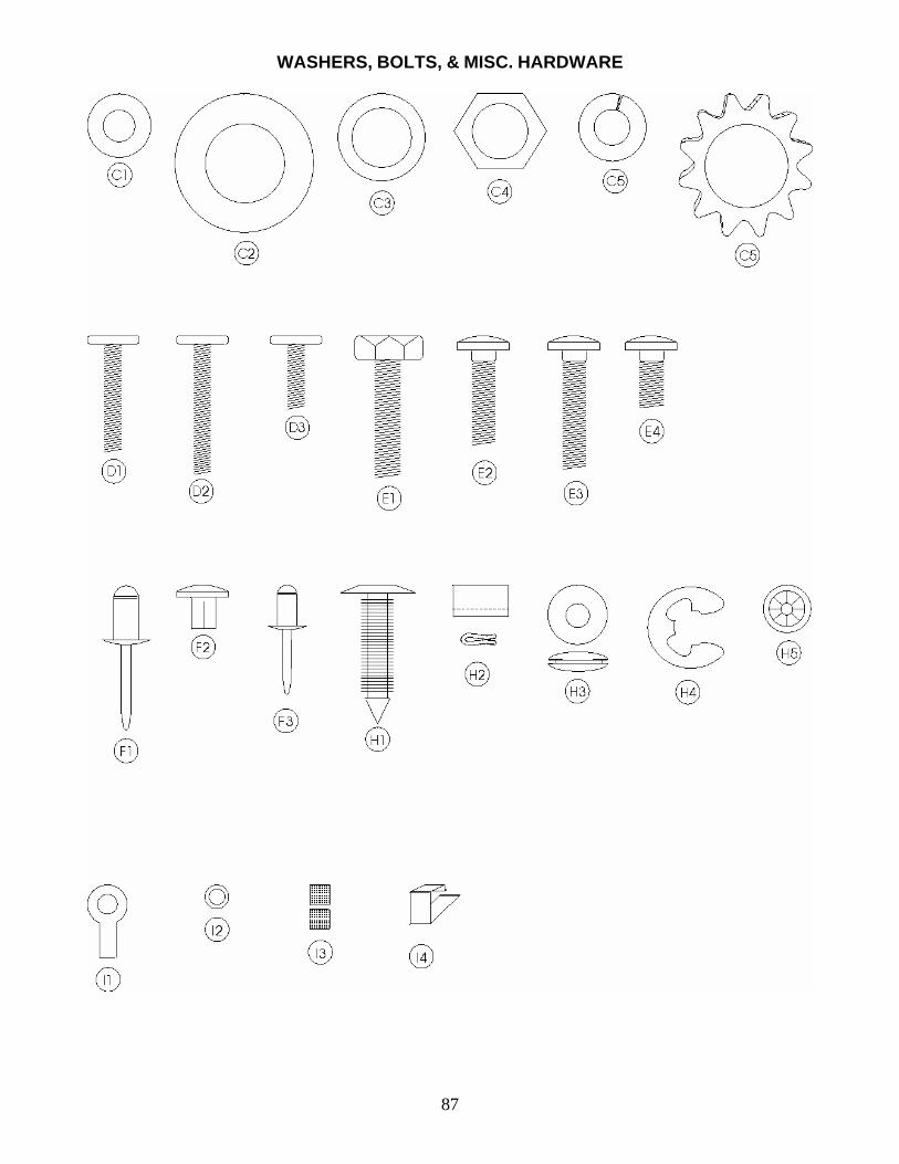
87
WASHERS, BOLTS, & MISC. HARDWARE
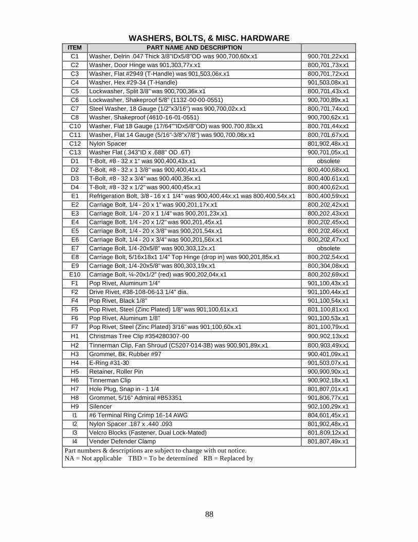
88
WASHERS, BOLTS, & MISC. HARDWARE
ITEM PART NAME AND DESCRIPTION C1 Washer, Delrin .047 Thick 3/8"IDx5/8"OD was 900,700,60x.x1 900,701,22x.x1 C2 Washer, Door Hinge was 901,303,77x.x1 800,701,73x.x1 C3 Washer, Flat #2949 (T-Handle) was 901,503,06x.x1 800,701,72x.x1 C4 Washer, Hex #29-34 (T-Handle) 901,503,08x.x1 C5 Lockwasher, Split 3/8" was 900,700,36x.x1 800,701,43x.x1 C6 Lockwasher, Shakeproof 5/8" (1132-00-00-0551) 900,700,89x.x1 C7 Steel Washer, 18 Gauge (1/2"x3/16") was 900,700,02x.x1 800,701,74x.x1 C8 Washer, Shakeproof (4610-16-01-0551) 900,700,62x.x1 C10 Washer, Flat 18 Gauge (17/64""IDx5/8"OD) was 900,700,83x.x1 800,701,44x.x1 C11 Washer, Flat 14 Gauge (5/16"-3/8"x7/8") was 900,700,08x.x1 800,701,67x.x1 C12 Nylon Spacer 801,902,48x.x1 C13 Washer Flat (.343"ID x .688" OD .6T) 900,701,05x.x1 D1 T-Bolt, #8 - 32 x 1" was 900,400,43x.x1 obsolete D2 T-Bolt, #8 - 32 x 1 3/8" was 900,400,41x.x1 800,400,68x.x1 D3 T-Bolt, #8 - 32 x 3/4" was 900,400,35x.x1 800,400.61x.x1 D4 T-Bolt, #8 - 32 x 1/2" was 900,400,45x.x1 800,400,62x.x1 E1 Refrigeration Bolt, 3/8 - 16 x 1 1/4" was 900,400,44x.x1 was 800,400,54x.x1 800,400,59x.x1 E2 Carriage Bolt, 1/4 - 20 x 1" was 900,201,17x.x1 800,202,42x.x1 E3 Carriage Bolt, 1/4 - 20 x 1 1/4" was 900,201,23x.x1 800,202,43x.x1 E4 Carriage Bolt, 1/4 - 20 x 1/2" was 900,201,45x.x1 800,202,45x.x1 E5 Carriage Bolt, 1/4 - 20 x 3/8" was 900,201,54x.x1 800,202,46x.x1 E6 Carriage Bolt, 1/4 - 20 x 3/4" was 900,201,56x.x1 800,202,47x.x1 E7 Carriage Bolt, 1/4-20x5/8" was 900,303,12x.x1 obsolete E8 Carriage Bolt, 5/16x18x1 1/4" Top Hinge (drop in) was 900,201,85x.x1 800,202,54x.x1 E9 Carriage Bolt, 1/4-20x5/8" was 800,303,19x.x1 800,304,08x.x1
E10 Carriage Bolt, ¼-20x1/2” (red) was 900,202,04x.x1 800,202,69x.x1 F1 Pop Rivet, Aluminum 1/4" 901,100,43x.x1 F2 Drive Rivet, #38-108-06-13 1/4" dia. 901,100,44x.x1 F4 Pop Rivet, Black 1/8" 901,100,54x.x1 F5 Pop Rivet, Steel (Zinc Plated) 1/8" was 901,100,61x.x1 801,100,81x.x1 F6 Pop Rivet, Aluminum 1/8" 901,100,53x.x1 F7 Pop Rivet, Steel (Zinc Plated) 3/16" was 901,100,60x.x1 801,100,79x.x1 H1 Christmas Tree Clip #354280307-00 900,902,13x.x1 H2 Tinnerman Clip, Fan Shroud (C5207-014-3B) was 900,901,89x.x1 800,903,49x.x1 H3 Grommet, Bk. Rubber #97 900,401,09x.x1 H4 E-Ring #31-30 901,503,07x.x1 H5 Retainer, Roller Pin 900,900,90x.x1 H6 Tinnerman Clip 900,902,18x.x1 H7 Hole Plug, Snap in - 1 1/4 801,807,01x.x1 H8 Grommet, 5/16" Admiral #B53351 901,806,77x.x1 H9 Silencer 902,100,29x.x1 I1 #6 Terminal Ring Crimp 16-14 AWG 804,601,45x.x1 I2 Nylon Spacer .187 x .440 .093 801,902,48x.x1 I3 Velcro Blocks (Fastener, Dual Lock-Mated) 801,809,12x.x1 I4 Vender Defender Clamp 801,807,49x.x1
Part numbers & descriptions are subject to change with out notice. NA = Not applicable TBD = To be determined RB = Replaced by
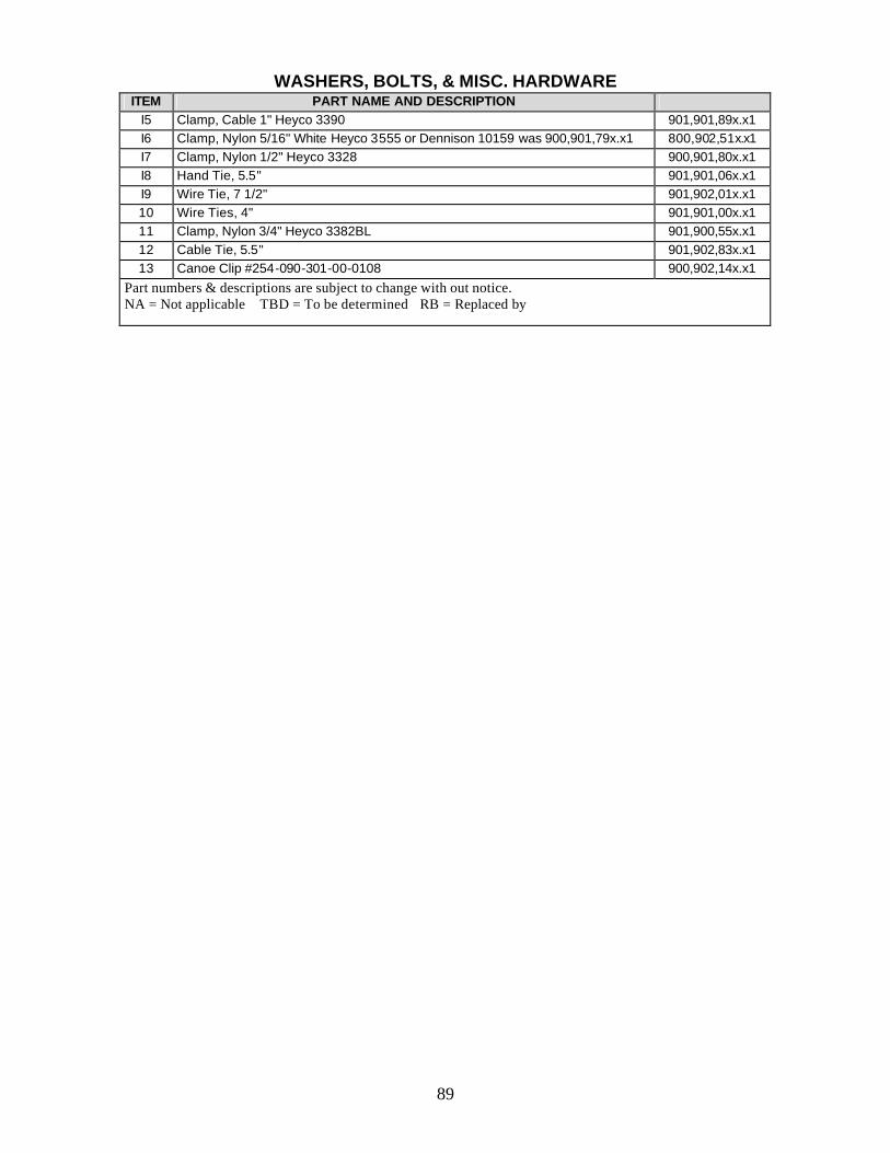
89
WASHERS, BOLTS, & MISC. HARDWARE
ITEM PART NAME AND DESCRIPTION I5 Clamp, Cable 1" Heyco 3390 901,901,89x.x1 I6 Clamp, Nylon 5/16" White Heyco 3555 or Dennison 10159 was 900,901,79x.x1 800,902,51x.x1 I7 Clamp, Nylon 1/2" Heyco 3328 900,901,80x.x1 I8 Hand Tie, 5.5" 901,901,06x.x1 I9 Wire Tie, 7 1/2" 901,902,01x.x1 10 Wire Ties, 4" 901,901,00x.x1 11 Clamp, Nylon 3/4" Heyco 3382BL 901,900,55x.x1 12 Cable Tie, 5.5" 901,902,83x.x1 13 Canoe Clip #254-090-301-00-0108 900,902,14x.x1
Part numbers & descriptions are subject to change with out notice. NA = Not applicable TBD = To be determined RB = Replaced by