Embed Size (px)
Citation preview
1
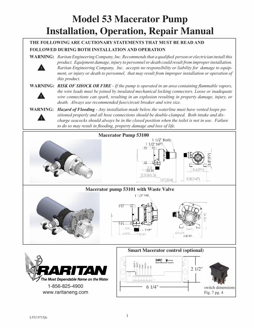
THE FOLLOWING ARE CAUTIONARY STATEMENTS THAT MUST BE READ AND FOLLOWED DURING BOTH INSTALLATION AND OPERATION WARNING: Raritan Engineering Company, Inc. Recommends that a qualified person or electrician install this
product. Equipment damage, injury to personnel or death could result from improper installation. Raritan Engineering Company, Inc. accepts no responsibility or liability for damage to equip-ment, or injury or death to personnel, that may result from improper installation or operation of this product.
WARNING: RISK OF SHOCK OR FIRE - If the pump is operated in an area containing flammable vapors, the wire leads must be joined by insulated mechanical locking connectors. Loose or inadequate wire connections can spark, resulting in an explosion resulting in property damage, injury, or death. Always use recommended fuse/circuit breaker and wire size.
WARNING: Hazard of Flooding - Any installation made below the waterline must have vented loops po-sitioned properly and all hose connections should be double-clamped. Both intake and dis-charge seacocks should always be in the closed position when the toilet is not in use. Failure to do so may result in flooding, property damage and loss of life.
Model 53 Macerator PumpInstallation, Operation, Repair Manual
1-856-825-4900www.raritaneng.com
Macerator Pump 53100
Macerator pump 53101 with Waste Valve
Smart Macerator control (optional)
6 1/4"
2 1/2"
switch dimensions Fig. 7 pg. 4
L552 0715jlc

2
OP
ER
ATI
ON Designed to empty marine and RV holding tanks
of normal waste and fish boxes of scales and residual waste. The unique dual-cut blade design ensures waste is ground up thoroughly. Marine pump out must be in proper discharge zones only. This macerator will not handle hard objects, rags, or feminine napkins.The optional Smart macerator control monitors pump motor and prevent pump damage due to priming failure or dry running. It also protects motor against overload. If power to control is not turned off, smart control will prevent impeller sticking by jogging impeller once every seven days of non- use.
PUMP IS INTERMITTENT DUTY ONLY!• Make sure Waste valve to pump and discharge
valve [if equipped] are both open. Turn on momentary switch and pump out tank.
• When tank is empty, pump will get louder with a high pitch sound. Immediately turn pump off, or damage to impeller and housing will occur. If pump is equipped with smart macerator control pump will turn off after 5 seconds of dry running
• If not equipped with smart macerator control do not run pump dry for more than 15 – 20 seconds. Flush tank and pump with water after each use. This macerator will handle normal waste, tissues, cigarettes, fish scales, etc. It is not designed to handle large hard objects such as large bones or fruit pits.
Periodic Maintenance and Storage: Flush with water after each use. Check wire connections oc-casionally. After periods of non-use, impeller can stick. To loosen, open rear shaft cover and turn motor shaft clockwise with a flat tip screwdriver. Then replace shaft cover. For extended periods of non-use, pump impeller can be lubricated by run-ning a small amount of mineral oil through hold-ing tank system.
Maintenance: Turn off all power!Rear end cap/ motor shaft slot access:Remove cap over the shaft
SMART MACERATOR CONTROL Smart macerator control (SMC) monitors motor and pump to prevent dry run and overload.SMC control has following features:1. If pump does not prime within 7 seconds,
SMC control will shut down the pump.2. If pumps runs dry for 5 seconds , SMC
control will shut down the pump. 3. If pump draws more than 20 amps, control
will shut down pump.4. LED at the switch and on the board will flash
if there is shut down due to priming failure or dry run. LED will stay on if shutdown is due to overload. SMC control can be reset by turning off and on switch. Power need not be turned off.
5. If power is not turned off to the control, control will jog macerator pump for few milliseconds every seven days of idle to prevent binding of impeller.
NOTE: Reverse polarity will run pump as soon as power is turned on even if switch is not on. Power must be turned off immediately (within 2 minutes) and polarity should be corrected to avoid permanent damage to the control.
A Maintenance Tip!Loosen stuck impeller by turning motor shaft clockwise from rear with a flat-tipped screwdriver.
L552 0715jlc
3
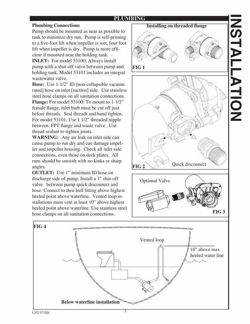
Installing on threaded flangePlumbing ConnectionsPump should be mounted as near as possible to tank to minimize dry run. Pump is self-priming to a five-foot lift when impeller is wet, four foot lift when impeller is dry. Pump is more effi-cient if mounted near the holding tank. INLET: For model 53100; Always install pump with a shut-off valve between pump and holding tank. Model 53101 includes an integral wastewater valve.Hose: Use 1-1/2” ID [non-collapsible vacuum rated] hose on inlet [suction] side. Use stainless steel hose clamps on all sanitation connections.Flange: For model 53100: To mount to 1-1/2” female flange, inlet barb must be cut off just before threads. Seal threads and hand tighten. For model 53101: Use 1 1/2" threaded nipple between FPT flange and waste valve . Use thread sealant to tighten joints.WARNING: Any air leak on inlet side can cause pump to run dry and can damage impel-ler and impeller housing. Check all inlet side connections, even those on deck plates. All runs should be smooth with no kinks or sharp angles.OUTLET: Use 1” minimum ID hose on discharge side of pump. Install a 1" shut-off valve between pump quick disconnect and hose. Connect to thru-hull fitting above highest heeled point above waterline. Vented loop in-stallations must vent at least 10” above highest heeled point above waterline. Use stainless steel hose clamps on all sanitation connections.
FIG 4
INS
TALLA
TIONPLUMBING
Quick disconnect
FIG 1
FIG 2
Optional Valve
FIG 3
Below waterline installation
10" above max heeled water line
Vented loop
L552 0715jlc

4
WIRINGWARNING: Hazard of Shock and Fire• Alwaysuseproperwire,wire
connectors and fuse/circuit breaker. See Specification Chart.
• Securewireproperly.• Donotconnectotherequipmentto
macerator circuit.• Makesurepowerisoffbeforeproceeding.• Useproperwireterminalsifneededforall wire connections.1. Determineproperwiresizeby
measuring distance from:• PowerSourcetoswitchtopumpmotor
and back to power source.• Formodelswithsmartmacerator
control include distance from power source to controller to pump and back.
2. Select proper wire and fuse/circuit breakersizefromSpecificationsonInstallation page.
3. Install fuse/circuit breaker in positive line at source.
Wiring with ON_OFF switch (FIG 5):
NOTE: Switch is not included . Mount switch near macerator pump so that operator can hear change in pump sound when tank is empty. If mounting in area whereignitionprotectionisrequireduseonly ignition protected switch.4. wireasperFig5.
Wiring with Optional Smart Macerator Control (FIG 6):
NOTE:Includedswitch(ESR03)(FIG7)should only be installed in area not requiringignitionprotection.Wiresneeded between switch and control are not included.
BATT
PUMP
+ -
Black
Fuse/Circuit
Breaker
Fuse/Circuit
Breaker
Switch
Orange/Red
BA
TT
-
BA
TT
+
RARITANSMC
SW
-
SW
/LE
D+
PU
MP
-
PU
MP
+
Smart Macerator Control
LE
D-
INS
TALL
ATI
ON
Wiring with on-off switch
Wiring with Smart Macerator Control
FIG 5
FIG 6
16 AWG
Switch (ESR03) CUTOUT 0.756 (19.2) x 0.512(13)
wiring
FIG 7
Orange Black
Fuse/Circuit Breaker
L552 0715jlc
5
Units Voltage
Circuit Breaker/Fuse sizes(AMPS)
Macerator amps @nominal voltage
10 Feet
20 Feet30
Feet40
Feet50 Feet
12V 25 16 12AWG 10AWG 8AWG 6AWG 6AWG
24V 15 8 14AWG 10AWG 10AWG 8AWG 6AWG
SP
EC
IFICA
TION
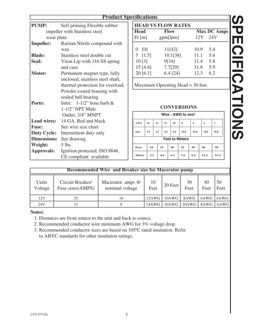
SHEAD VS FLOW RATESHead Flow Max DC AmpsFt [m] gpm[lpm] 12V 24V
0 [0] 11[42] 10.9 5,4 5 [1.5] 10.1[38] 11.1 5.6 10 [3] 9[34] 11.4 5.8 15 [4.6] 7.7[29] 11.8 5.9 20 [6.1] 6.4 [24] 12.3 6.2 Maximum Operating Head = 30 feet
PUMP: Self priming Flexible rubber impeller with Stainless steel wear plate Impeller: Raritan Nitrile compound with waxBlade: Stainless steel double cutSeal: Viton Lip with 316 SS spring and caseMotor: Permanent magnet type, fully enclosed, stainless steel shaft, thermal protection for overload, Powder coated housing with sealed ball bearingPorts: Inlet: 1-1/2” hose barb & 1-1/2” NPT Male Outlet: 3/4” MNPT Lead wires: 14 GA, Red and blackFuse: See wire size chartDuty Cycle: Intermittent duty onlyDimensions: See drawingWeight: 5 lbs.Approvals: Ignition protected, ISO 8846, CE compliant available
Product Specifications
Recommended Wire and Breaker size for Macerator pump
CONVERSIONSWire - AWG to mm2
Feet to Meters
Feet 10 15 20 25 30 40 50
Meter 3.1 4.6 6.1 7.6 9.2 12.2 15.2
AWG 16 14 12 10 8 6 4 2
mm2 1.5 2.5 4.0 6.0 10.0 16.0 25.0 35.0
Notes: 1. Distances are from source to the unit and back to source. 2. Recommended conductor wire minimum AWG for 3% voltage drop. 3. Recommended conductor sizes are based on 1050C rated insulation. Refer to ABYC standards for other insulation ratings.
L552 0715jlc
6
PA
RTS
LIS
TEXPLODED PARTS VIEW
EX
PLO
DE
D P
AR
TS V
IEW
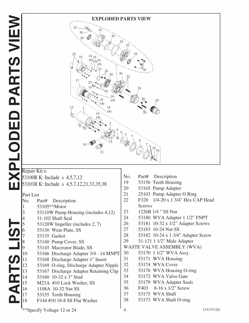
Part ListNo. Part# Description 1 53105**Motor3 53110W Pump Housing (includes 4,12)4 31-102 Shaft Seal 5 53120W Impeller (includes 2, 7)6 53130 Wear Plate, SS7 53135 Gasket 8 53140 Pump Cover, SS9 53145 Macerator Blade, SS10 53166 Discharge Adapter 3/4 - 14 MNPT 11 53168 Discharge Adapter 1" Insert12 53169 O-ring, Discharge Adapter Nipple13 53167 Discharge Adapter Retaining Clip14 53160 10-32 x 3" Stud15 M23A #10 Lock Washer, SS16 1108A 10-32 Nut SS17 53155 Teeth Housing18 F144 #10 18-8 SS Flat Washer
No. Part# Description19 53156 Teeth Housing20 53165 Pump Adapter21 25103 Pump Adapter O Ring22 F326 1/4-20 x 1 3/4" Hex CAP Head Screws 23 1226B 1/4 " SS Nut24 53180 WVA Adapter 1 1/2" FNPT26 53181 10-32 x 1/2" Adapter Screws27 53183 10-24 Nut SS 28 53182 10-24 x 1 3/4" Adapter Screw 29 31-121 1 1/2" Male AdapterWASTE VALVE ASSEMBLY (WVA)30 53170 1 1/2" WVA Assy.31 53171 WVA Housing32 53174 WVA Cover33 53176 WVA Housing O-ring 34 53172 WVA Valve Gate35 53179 WVA Adapter Seals36 F403 8-16 x 1/2" Screw37 53175 WVA Shaft38 53173 WVA Shaft O-ring
**Specify Voltage 12 or 24
Repair Kit s: 53100R K: Include s 4,5,7,12 53101R K: Include s 4,5,7,12,21,33,35,38
L552 0715jlc

7
TRO
UB
LES
HO
OTIN
GMaintenance: If pump is not used for long period, impeller may bind to the pump housing causing overload. Impeller can be freed by turning the motor shaft (see Fig 8) CAUTION: Turn off all power prior to removing the plastic cap and rotating shaft with a screw driver. Note: Smart macerator control will jog the shaft every 7 days of non-use automatically preventing binding.
Pump disassembly:Model 53101:Close the waste valve by turning valve shutoff socket counterclockwise. Remove two screws(22). Pull waste water valve away from the pump.Model 53100:Disconnect inlet hose.All models:Shutoff discharge valve if installed.Remove clip(13) and remove fitting(10/11) .Pump can be unbolted and removed for disassembly to a convenient location.
Remove 4 cover screws (14). Remove housing (19 or 17)) and O-ring (3). Remove hex nut (16) and cutter blades (9). It may be necessary to hold the motor shaft steady. Insert a screwdriver into slot on motor shaft (see slot access above), or slip a thin wrench (9/32” [7mm]) behind blades onto flat of motor shaft. Remove top wear plate (8), gasket (7), impeller (5) and bottom wear plate (6). Remove impeller housing (3) and shaft seal (4).
Pump reassembly:Follow disassembly in reverse order.Tip: Turn rubber impeller counter clockwise to install in the housing.
Remove screws Valve shutoff
FIG 8
FIG 9
LEDBlinking: Dry runOn: Overload
FIG 10
Troubleshooting1.Pump makes loud noise: Make sure pump is not running dry. 2. Pumps runs but does not empty tank: Impeller may be worn or broken, replace impeller.Smart control:1. Pump shuts down after 7 seconds and LED is blinking: Pump ran dry. Check for water level and check for any leaks in the input plumbing.2. Pump shuts down and LED is ON: Motor is overloaded. Pump may have some foreign object lodged in the macerator, or broken impeller.
L552 0715jlc

8
Raritan Engineering Company warrants to the original purchaser that this product is free of defects in
materials or workmanship for a period of one year from the product’s date of purchase. Should this
product prove defective by reason of improper workmanship and/or materials within the warranty
period, Raritan shall, at its sole option, repair or replace the product.
1. TO OBTAIN WARRANTY SERVICE, Consumer must deliver the product prepaid, together with a
detailed description of the problem, to Raritan at 530 Orange St., Millville, N.J. 08332, or 3101 SW
2nd Ave. Ft. Lauderdale, FL 33315. When requesting warranty service, purchaser must present a
sales slip or other document which establishes proof of purchase. THE RETURN OF THE OWNER
REGISTRATION CARD IS NOT A CONDITION PRECEDENT OF WARRANTY COVERAGE.
However, please complete and return the owner Registration Card so that Raritan can contact you
should a question of safety arise which could affect you.
2. THIS WARRANTY DOES NOT COVER defects caused by modifications, alterations, repairs or
service of this product by anyone other than Raritan; defects in materials or workmanship supplied by
others in the process of installation of this product; defects caused by installation of this product other
than in accordance with the manufacturer’s recommended installation instructions or standard industry
procedures; physical abuse to, or misuse of, this product. This warranty also does not cover damages
to equipment caused by fire, flood, external water, excessive corrosion or Act of God.
3. ANY EXPRESS WARRANTY NOT PROVIDED HEREIN, AND ANY REMEDY FOR BREACH
OF CONTRACT WHICH BUT FOR THIS PROVISION MIGHT ARISE BY IMPLICATION
OR OPERATION OF LAW, IS HEREBY EXCLUDED AND DISCLAIMED. ALL IMPLIED
WARRANTIES SUCH AS THOSE OF MERCHANTABILITY AND OF FITNESS FOR A
PARTICULAR PURPOSE, IF APPLICABLE, AS WELL AS ANY IMPLIED WARRANTIES
WHICH MIGHT ARISE BY IMPLICATION OF LAW, ARE EXPRESSLY LIMITED TO A TERM
OF ONE YEAR. SOME STATES DO NOT ALLOW LIMITATIONS ON HOW LONG A LIMITED
WARRANTY LASTS, SO THE ABOVE LIMITATION MAY NOT APPLY TO YOU.
4. UNDER NO CIRCUMSTANCES SHALL RARITAN BE LIABLE TO PURCHASER OR ANY OTHER
PERSONS FOR ANY SPECIAL OR CONSEQUENTIAL DAMAGES, WHETHER ARISING OUT
OF BREACH OF WARRANTY, BREACH OF CONTRACT, OR OTHERWISE. SOME STATES
DO NOT ALLOW THE EXCLUSION OR LIMITATION OF INCIDENTAL OR CONSEQUENTIAL
DAMAGES, SO THE ABOVE LIMITATION OR EXCLUSION MAY NOT APPLY TO YOU.
5. No other person or entity is authorized to make any express warranty, promise or affirmation of fact or
to assume any other liability on behalf of Raritan in connection with its products except as specifically
set forth in this warranty.
6. This warranty gives you specific legal rights, and you may also have other rights which vary from state
to state.
530 Orange Street, Millville, NJ 08332 USATelephone: 856-825-4900 FAX: 856-825-4409
www.raritaneng.comSouthern Office and Plant:3101 SW Second Avenue, Fort Lauderdale, FL 33315 USATelephone: 954-525-0378 FAX: 954-764-4370
LIMITED WARRANTY
L552 0715jlc Specifications Subject to Change Without Notice Printed in U.S.A.