Embed Size (px)
Citation preview

MODEL 518
CONTROLLED ENVIRONMENT CHAMBER
USER MANUAL
TABLE OF CONTENTS
1.0 Introduction 1 2.0 General Description 1 2.1 Chamber 1 2.2 Humidity 2 2.3 Temperature 3 2.4 Humidity/Temperature Control Unit 3 2.5 System Operation 4 3.0 Detailed System Description 6 3.1 Chamber 6 3.2 Control Unit 6 3.3 Power Panel 10 3.4 Environmental Control Systems Access Panel 12 4.0 Installation 13 4.1 Initial Set-Up 13 4.2 Initial System Checkout 14 5.0 Operation 15 5.1 Placing Instrumentation Inside the Chamber 15 5.2 Controlling Relative Humidity 16 5.3 Controlling Temperature 16 5.4 Obtaining a Given Humidity and Temperature Condition 17 5.5 Maintaining Selected Humidity and Temperature Level 18 6.0 Calibration 20 6.1 Humidity Controller 20 6.2 Temperature Controller 25 7.0 Maintenance 27 7.1 Desiccator 27 7.2 Ultrasonic Humidifier 27 7.3 Fluorescent Lamp Replacement 29 8.0 Troubleshooting 30 8.1 Humidity Control System 30 8.2 Temperature Control System 31 9.0 Warranty 33
LIST OF FIGURES 2.5-1 Automatic Humidity/Temperature Control Block Diagram 4 3.2-1 Control System Front Panel 7 3.3-1 Power Panel 11 4.1.1-1 Cooling System Installation 13 4.1.2-1 Humidifier System Installation 14 5.4-1 Maximum R.H. Level Versus Controlled Temperature (Table) 17 6.1.1-1 Calibration Adjustment Points For Humidity Controller Unit Printed Circuit
Board 22
6.1.2.-1 R.H. Sensor Calibration Adjustment Location 24 6.2.1-1 Calibration Adjustment Points for Temperature Controller Printed Circuit
Board 26
1
1.0 INTRODUCTION
2.0 GENERAL DESCRIPTION
2.1 Chamber
The left hand side of the Chamber consists of a 12"W x 4"H opening with a hinged access door. Towards the rear of the Chamber is a 1.25" ID access hole for feeding cables and tubing to instrumentation placed inside. This hole is then sealed using a soft putty compound.
The front of the Chamber consists of a large door containing a pair of accordion neoprene gloves. The access opening is 32"W x 14"H which enables large objects to be placed inside. To the right of the front door is the humidity and temperature control module. This module is easily removed for servicing by loosening the four (4) captive mounting screws.
The right hand side of the Chamber contains the power panel, desiccator, humidifier cooling systems access panel and a 3" fan for reducing any heat build-up in the Control component. The rear of the Chamber contains a removable panel to which a 15 Watt florescent light fixture is mounted. This assembly slides into a sub-chamber that is installed inside the main chamber.
Many applications require a controlled environment for testing, fabricating and/or storage. The Model 518 Automatically Controlled Environmental Chamber is specifically designed to meet this requirement. The Model 518 is a completely integrated system that incorporates precision automatic humidity and temperature control systems that can control the relative humidity to within ±0.5% R.H. and the temperature to within ±1.0°F (0.5°C) of the desired levels. The Chamber is capable of precisely controlling the relative humidity over the range of 5 - 98% at lab ambient and the temperature over the range of 32 - 122°F (0-50°C). The maximum RH level obtainable with heating or cooling will be a function of the temperature selected because of the drying effects of the heater and the dry CO2 gas cooling system.
The Model 518 Automatically Controlled Environmental Chamber is an airtight acrylic glove box that incorporates a built-in humidity and temperature control system. The overall size of the Chamber is 47"W x 25.5"D x 22"H including the controller compartment. The useable space in the controlled environment section is approximately 13 cubic feet. The entire section measures 39"W x 22.5"D x 22"H. The Chamber is fabricated from both 0.25" and 0.375" clear and white acrylic. It is uninsulated and designed for those applications where only a moderate temperature (±40°F) range must be maintained around room ambient.
2
Inside the Chamber is a perforated aluminum panel that houses a fan, heater and accessory AC outlet. This panel is secured by six (6) thumb screws accessed from inside the Chamber.
The inside wall separating the controlled environment section from the control equipment section contains the fittings for mounting the humidity and temperature sensors, the dehumidification, humidification, and cooling input fittings. The sensors are mounted through the wall via bulkhead fittings and are located towards the center of the wall. A duplex AC outlet with a sealed protective cover is also located on this wall.
The relative humidity within the controlled environment chamber is established using a desiccant drying system for dehumidification and an ultrasonic humidifier for humidification which are controlled by the Automatic Humidity Controller module.
The dehumidification system utilizes Calcium Sulfate (CaSo4) desiccant to dry the air within the chamber. A built-in pump draws air from the chamber and pumps it through a desiccator unit plugged into the panel located on the right hand side of the Chamber. The desiccant absorbs the moisture that is in the air being pumped through it. This dried air is pumped back into the chamber. The process is continued until the humidity inside the chamber is equal to the level set by the controller. The CaSO4 contains an indicator that turns the normally blue colored desiccant pink as it absorbs moisture. When the entire cylinder turns pink, it is time for the desiccant to be renewed or replaced.
The humidification system is based around a commercially available ultrasonic humidifier which is specially modified for this application. The humidifier contains a water tank, a fan and an ultrasonic amplifier and transducer. The ultrasonic transducer breaks up the water molecules into a fine mist that is forced into the chamber by the fan. The fan installed in the chamber circulates the moist air to produce an even humidity. The humidifier is turned on and off by the Controller to maintain the desired level.
Some applications may require dry nitrogen for dehumidification and non-ultrasonic generated moisture for humidification. ETS can supply solenoid valves and other types of humidifiers if required. Contact ETS for details.
2.3 Temperature
The Temperature within the chamber is maintained by using a 500 Watt electric heater for heating and CO2 for cooling which are then controlled by the Automatic Temperature Controller module.
2.2 Humidity
3
The heater is an element located behind the aluminum panel. A thermal safety switch is connected in series with the heater that cuts off power if the temperature inside the chamber exceeds 135°F. The Controller is also limited to 130°F. The Controller turns the heater on and off to maintain the desired temperature. Cooling is produced by converting liquid CO2 to a gas. A high pressure solenoid valve is connected to a user supplied CO2 tank (tank must be equipped with a dip tube inside) via a 48" high pressure hose. When the solenoid valve opens, high pressure liquid is forced through a pin hole opening which instantly converts it to a gas. The Controller turns the solenoid valve on and off to control the cooling.
NOTE: The CO2 gas is very dry and will limit the maximum RH level achievable when the cooling system is used.
2.4 Humidity/Temperature Control Unit
The Control Unit consists of a dedicated ETS Model 514 Automatic Humidity Controller and an ETS Model 513A Automatic Temperature Controller. In addition, the Control Unit has Power switches to control system power, the 15 Watt florescent light and the internal circulating fan. The Control Unit is a self-contained system that can be removed from the Chamber for recalibration or service by simply loosening the four (4) captive screws and unplugging the cable harnesses from the rear panel. The Control Unit has two (2) modules: The RELATIVE HUMIDITY control module and the TEMPERATURE control module. For those applications where no temperature control is required, the optional TEMPERATURE readout only module can be specified. The RELATIVE HUMIDITY control module provides the necessary indicators and controls to set the desired humidity level and to measure the actual humidity inside the chamber. A 3½ digit LCD readout indicates both the measured humidity level and the set point desired with a resolution of 0.1% RH. A 10-turn precision potentiometer is used to adjust the set-point. ON/OFF rocker switches are used to select the dehumidification and humidification functions. When both of these switches are in the OFF position, the module operates only as a precision hygrometer. The humidity is sensed by a capacitive type sensor which has an element whose capacitance is proportional to humidity. This type of sensor provides a fast response over the entire 0-100% RH range with an accuracy of 2% RH from 0-90% and 3% above 90% at 20°C. (68°F.). The TEMPERATURE control module operates in a similar fashion to the RELATIVE HUMIDITY control module. The 3½ digit LCD readout displays temperature with a resolution of 0.1°. A front panel switch enables the user
4
to select either °F. or °C. Separate rocker switches control the heating and cooling functions. When both switches are in the OFF position, the module operates only as a precision temperature indicator. When the Model 518 Chamber is ordered without the automatic temperature control function, a temperature indicating module is provided. This module consists of only the 3½ digit LCD readout and the °F. and °C. selector switch. The temperature is sensed by a solid state integrated circuit sensor. The sensor output signal has a voltage output that is proportional to temperature. This type of sensor provides a fast response over the range of 0 - 100°C (32 - 199°F) with an accuracy of ±1°C (±1.8°F).
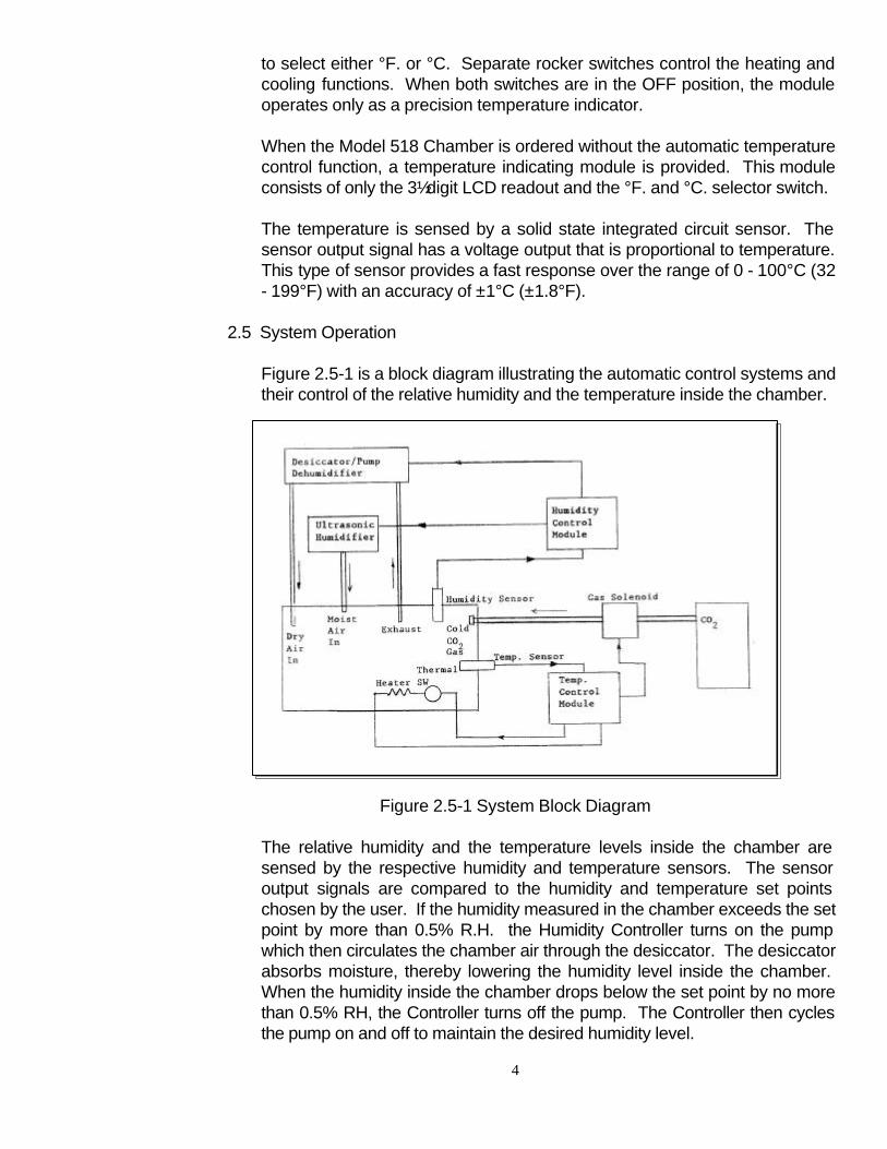
Figure 2.5-1 is a block diagram illustrating the automatic control systems and their control of the relative humidity and the temperature inside the chamber.
Figure 2.5-1 System Block Diagram
The relative humidity and the temperature levels inside the chamber are sensed by the respective humidity and temperature sensors. The sensor output signals are compared to the humidity and temperature set points chosen by the user. If the humidity measured in the chamber exceeds the set point by more than 0.5% R.H. the Humidity Controller turns on the pump which then circulates the chamber air through the desiccator. The desiccator absorbs moisture, thereby lowering the humidity level inside the chamber. When the humidity inside the chamber drops below the set point by no more than 0.5% RH, the Controller turns off the pump. The Controller then cycles the pump on and off to maintain the desired humidity level.
2.5 System Operation
5
If the measured humidity is below the set point by more than 0.5% RH the Controller cycles the humidifier on and off to maintain the desired humidity level. If the temperature measured inside the chamber exceeds the set point by more than 0.5°C (1.0°F) the Controller opens the solenoid valve that controls the flow of the CO2. When the temperature level drops below the set point by no more than 0.5°C. (1.0°F), the Controller turns off the solenoid valve. The Controller then cycles the cooling system on and off automatically to maintain the desired temperature. If the measured temperature is below the set point by more than 0.5°C (1.0°F.), the Controller turns on an electric heating element. The Controller then cycles the heater on and off automatically to maintain the desired temperature level. NOTE: Due to the retained heat in the heating element after it has been turned off the temperature inside the chamber will continue to rise approximately 1 - 3°C. (1.8 - 5.4°F). This overshoot should be taken into account when selecting the set point. The humidity and temperature systems are designed to operated in either the dehumidify (COOL) or the humidify (HEAT) modes. When both sets of function switches are ON, the Controllers will switch from one mode to the other causing the dehumidify (COOL) and humidify (HEAT) functions to constantly work against each other. The most efficient mode of operation is to have the Controllers operate the appropriate function relative to the ambient conditions outside the Chamber. Thus, when a humidity level below ambient is desired then only the DEHUMIDIFY function should be selected, and conversely, when a humidify level above ambient is desired then only the HUMIDIFY function should be selected. The same applies to the temperature functions. Power to operate all of the systems is controlled by solid state Triac circuits. When a system is to be activated the Controller turns on the respective Triac which supplies the necessary 115/230 VAC power to operate the system. A 4", 110 CFM fan is built into the chamber to constantly circulate the air inside to achieve a uniform environment.
6
3.0 DETAILED SYSTEM DESCRIPTION
3.1 Chamber The environmental section of the Chamber has two (2) access doors. The 4" x 12" side door is used to place test specimens and small objects inside the chamber without introducing a major disturbance to the environment inside. The door is secured by three (3), ¾-turn latches. A non-setting gasket provides an airtight seal. The 32" x 14" door on the front of the Chamber contains the rubber gloves. This door provides total access to the inside of the environmental section. Large test specimens and test instruments can be placed inside the chamber via this opening. The door is secured by eight (8) ¾-turn latches. A non-setting gasket provides an airtight seal. Special access ports or no access ports at all can be supplied utilizing custom built doors. If desired, several versions can be supplied for a single Chamber. Contact ETS for any special requirements.
A 15 Watt florescent light is incorporated in a sub-chamber inside the environmental controlled section. This light is controlled by a power switch located on the front control panel. A duplex AC outlet is mounted on the inside wall to provide power for any instrumentation that may be placed inside the chamber. This outlet accepts the standard North American 3- prong plug. When the System is configured for 230 VAC operation, 230 VAC is also available at this outlet. The outlet is fused for 8 amps at 115 VAC and 4 amps at 230 VAC.
The Control Unit, shown in Figure 3.2-1, is a completely self-contained system that incorporates the Automatic Humidity and Automatic Temperature control modules mounted onto the front panel, along with the system, light and fan power switches. The entire unit mounts to the Chamber by four (4) #6-32 captive fasteners. All connections to other components within the Chamber are made by either DIN or Molex connector interface to the rear panel. A 115/230 VAC selector switch is located on the rear panel to set the Controller for either 115 or 230 VAC operation.
3.2 Control Unit
7
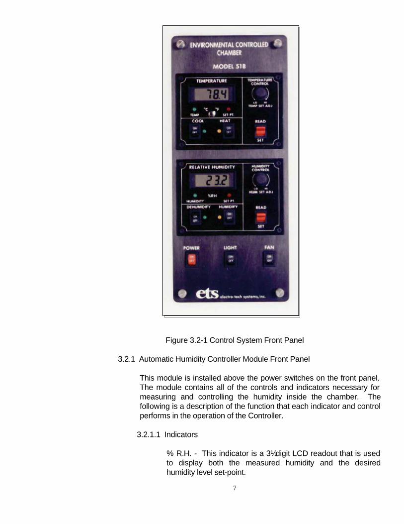
Figure 3.2-1 Control System Front Panel
3.2.1 Automatic Humidity Controller Module Front Panel
This module is installed above the power switches on the front panel. The module contains all of the controls and indicators necessary for measuring and controlling the humidity inside the chamber. The following is a description of the function that each indicator and control performs in the operation of the Controller.
3.2.1.1 Indicators
% R.H. - This indicator is a 3½ digit LCD readout that is used to display both the measured humidity and the desired humidity level set-point.
8
HUMIDITY-This indicator is a Green LED point source that shows that the HUMIDITY control selector switch is in the READ position and the LCD readout is displaying the measured relative humidity. SET-PT - This indicator is a Red LED point source that shows that the HUMIDITY CONTROL selector switch is in the SET position and the LCD readout is displaying the desired humidity level set point. DEHUMIDIFY - This indicator is a Green LED point source that shows that the DEHUMIDIFY control Triac has been activated and the dehumidifier system is on. HUMIDIFY - This indicator is a Yellow LED point source that shows that the HUMIDIFY control Triac has been activated and the humidifier system is on.
3.2.1.2 Controls
READ/SET - This control is a 2-position, spring loaded red switch. In the normal READ (Up) position, the measured humidity level is displayed on the LCD readout. When depressed to the SET position, the humidity level set- point is displayed on the LCD readout. Upon release, the switch returns to the READ position. HUM SET ADJ - This control is a precision 10-turn potentiometer with 0.25% linearity which is used to select the desired humidity set point level. In the fully counterclockwise position (LO), the readout will indicate 00.0 ±.2% RH and in the fully clockwise position (HI) the readout will indicate 100.0 ±.2% RH. DEHUMIDIFY ON/OFF - This switch, when in the ON position, places the system in the DEHUMIDIFY mode. When the measured humidity is above the set-point level, a control signal turns on the DEHUMIDIFY control TRIAC and 115/230 VAC is applied to the pump which activates the dehumidification system. When this switch is in the OFF position the dehumidification system will remain off irrespective of the RH level measured. HUMIDIFY ON/OFF - This switch, when in the ON position, places the system in the HUMIDIFY mode. When the measured humidity is below the set-point level a control signal turns on the HUMIDIFY control TRIAC and 115/230 VAC is
9
applied to the HUMIDIFY AC outlet on the power panel on the left side of the Chamber. This turns on the humidification system. When this switch is in the OFF position the humidification system will remain off irrespective of the RH level measured.
3.2.2 Automatic Temperature Controller Module Front Panel
The Automatic Temperature Controller module, shown in Figure 3.2.2-1 is located at the top of the main control panel. It contains all of the indicators and controls necessary for measuring and controlling the temperature inside the chamber. The following is a description of the function each indicator and control performs in the operation of the Controller.
3.2.2.1 Indicators
DISPLAY - This indicator is a 3½-digit LCD readout that is used to display both the measured temperature and the desired temperature set point. TEMPERATURE - This indicator is a Green LED point source that shows that the TEMPERATURE control selector switch is in the READ position and the LCD readout is displaying the measured temperature. SET-PT - This indicator is a Red LED point source that shows that the TEMPERATURE selector switch is in the SET position and the LCD readout is displaying the desired temperature set point. COOL - This indicator is a Green LED point source that shows that the COOL control TRIAC has been activated and that the cooling system is on. HEAT - This indicator is a Yellow LED point source that shows that the HEAT control TRIAC has been activated and that the heating system is on.
3.2.2.2 Controls
READ/SET - This control is a 2-position, spring loaded red paddle switch. In the normal READ (Up) position, the measured temperature is displayed on the LCD readout. When depressed to the SET position, the temperature set point is displayed on the LCD readout. Upon release, the switch returns to the READ position.
10
TEMP SET ADJ - This control is a precision 10-turn potentiometer with 0.25% linearity that is used to select the desired temperature set-point. In the fully counterclockwise position (LO), the readout will indicate approximately 0°C (32°F) and in the fully clockwise position (HI) the readout will indicate approximately 40°C (130°F). COOL ON/OFF - This switch, when in the ON position, places the system in the COOL mode. When the measured temperature is above the set-point level, a control signal turns on the COOL control TRIAC and 115/230 VAC activates the CO2 solenoid, which turns on the cooling system. When this switch is in the OFF position the cooling system will remain off irrespective of the temperature level measured. HEAT ON/OFF - This switch, when in the ON position, places the system in the HEAT mode. When the measured temperature is below the set-point level, a control signal turns on the HEAT control TRIAC and 115/230 VAC is applied to the heater. When this switch is in the OFF position the heater will remain off irrespective of the temperature measured. °C/°F - This toggle switch selects the temperature scale displayed on the LCD readout.
3.2.3 Temperature Readout Module Front Panel (Optional)
The Temperature Readout module is supplied as an option when only the relative humidity within the chamber is to be controlled. This module consists of only the LCD display and the toggle switch for selecting either °C or °F indication. Green and Red LED point source indicators display the respective temperature scale selected.
The Power Panel, shown in Figure 3.3-1, contains the input and output power receptacles, fuses and recorder outputs for remote monitoring and/or recording of the humidity and temperature. When the Model 518 is configured for 230 VAC operation the voltage select switch on the rear of the Controller Unit is set to 230 VAC, and a 230 VAC pump, and heater are installed. A step-down transformer is added to convert the 115 VAC light and humidifier to 230 VAC operation. A 230 VOLTS label is placed above the Power Input receptacle to indicate that the system has been adapted to 230 VAC operation. A 115 VAC label is placed below the HUMIDIFIER outlet to indicate that a 115 VAC humidifier must be used.
3.3 Power Panel
11
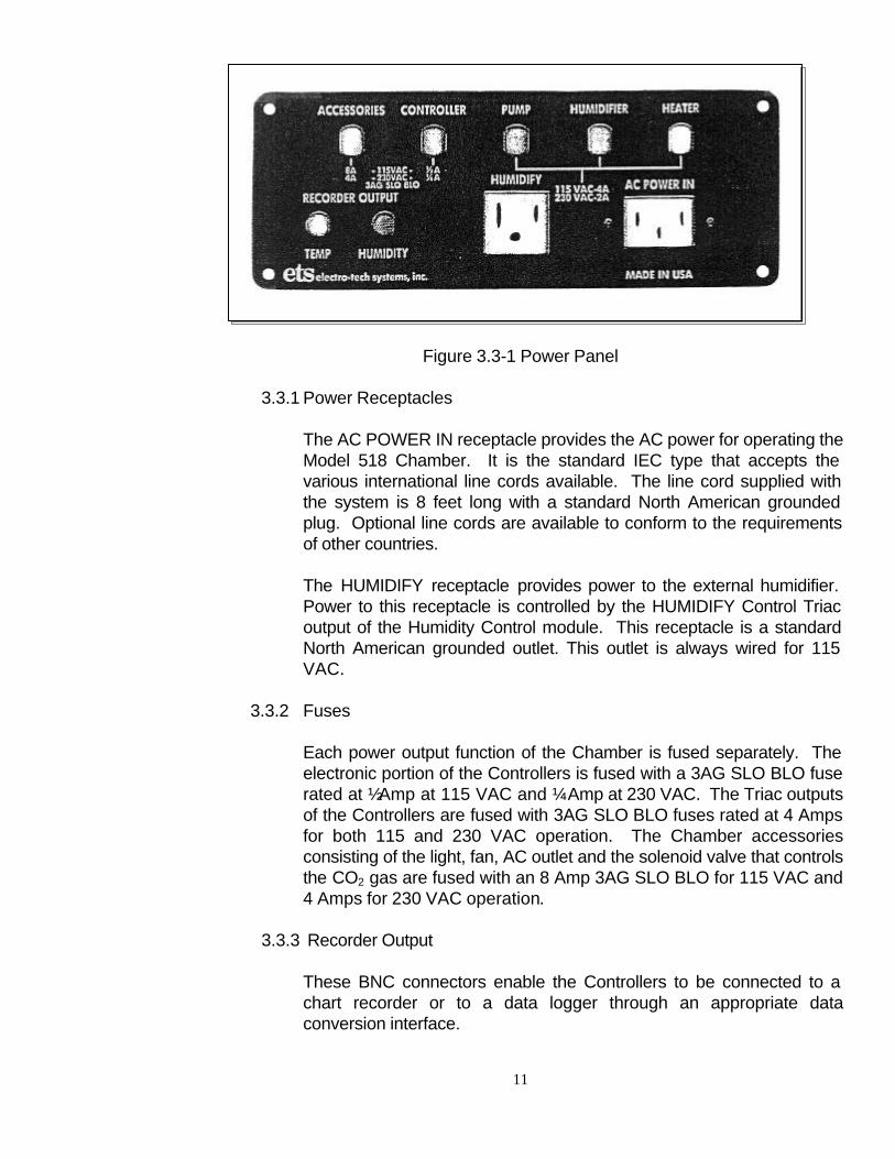
Figure 3.3-1 Power Panel
3.3.1 Power Receptacles
The AC POWER IN receptacle provides the AC power for operating the Model 518 Chamber. It is the standard IEC type that accepts the various international line cords available. The line cord supplied with the system is 8 feet long with a standard North American grounded plug. Optional line cords are available to conform to the requirements of other countries. The HUMIDIFY receptacle provides power to the external humidifier. Power to this receptacle is controlled by the HUMIDIFY Control Triac output of the Humidity Control module. This receptacle is a standard North American grounded outlet. This outlet is always wired for 115 VAC.
3.3.2 Fuses Each power output function of the Chamber is fused separately. The electronic portion of the Controllers is fused with a 3AG SLO BLO fuse rated at ½ Amp at 115 VAC and ¼ Amp at 230 VAC. The Triac outputs of the Controllers are fused with 3AG SLO BLO fuses rated at 4 Amps for both 115 and 230 VAC operation. The Chamber accessories consisting of the light, fan, AC outlet and the solenoid valve that controls the CO2 gas are fused with an 8 Amp 3AG SLO BLO for 115 VAC and 4 Amps for 230 VAC operation.
3.3.3 Recorder Output
These BNC connectors enable the Controllers to be connected to a chart recorder or to a data logger through an appropriate data conversion interface.
12
3.3.3.1 Humidity The HUMIDITY output signal is 0-0.5 Volts which corresponds to the humidity range of 0 - 100% RH.
3.3.3.2 Temperature
The Temperature output signal is 1 millivolt/°C (1mV/1.8°F). When negative temperatures are measured the RECORDER OUTPUT is also negative.
This Panel provides the interface between the dehumidification, humidification, cooling system and the chamber.
The desiccant within the drying unit is initially blue in color. As the desiccant absorbs the moisture it begins to change to a pink color starting at the bottom on the unit. When all of the desiccant turns pink it is necessary to insert a fresh drying unit. The desiccant can be renewed by pouring the contents into a tray one to three granules thick and heating it for one (1) hour at 200°C (400°F).
3.4.2 Humidifier
A hose barb fitting is located on the Access Panel that connects the moist air output from the humidifier to the Chamber. It accepts 1.0" I.D. plastic tubing.
3.4.3 Cooling
A male quick disconnect fitting is mounted to the Access Panel for coupling the 48” long high pressure hose to the user supplied CO2 tank. NOTE: The CO2 tank must have a dip tube that draws liquefied CO2 to the outlet. The cooling system will not work if only CO2 gas is used. The tank is usually marked "DIP".
3.4.1 Desiccator Two bulkhead fittings, mounted 8.75 inches apart, are used to mount the desiccant drying unit. The input/output hose barbs molded in the unit are plugged into the bulkhead fittings. The unit is easily replaced without affecting the RH level inside the chamber.
3.4 Environmental Control System Access Panel
13
4.0 INSTALLATION
Carefully unpack the Chamber from its double corrugated shipping container. Inspect the Chamber for any shipping damage prior to installation. If any damage is observed contact the carrier and ETS immediately. Place the Chamber on a flat sturdy surface that measures at least 48" wide by 30" deep. Do not place the Chamber against the wall since this will block the air vent to the electronics compartment. Unpack the accessories and inspect for damage. The accessory box contains the humidifier, desiccator, 5 pound jar of extra desiccant, high pressure hose for the cooling function, and the necessary tubing and sealing putty to complete the installation.
4.1.1 Cooling
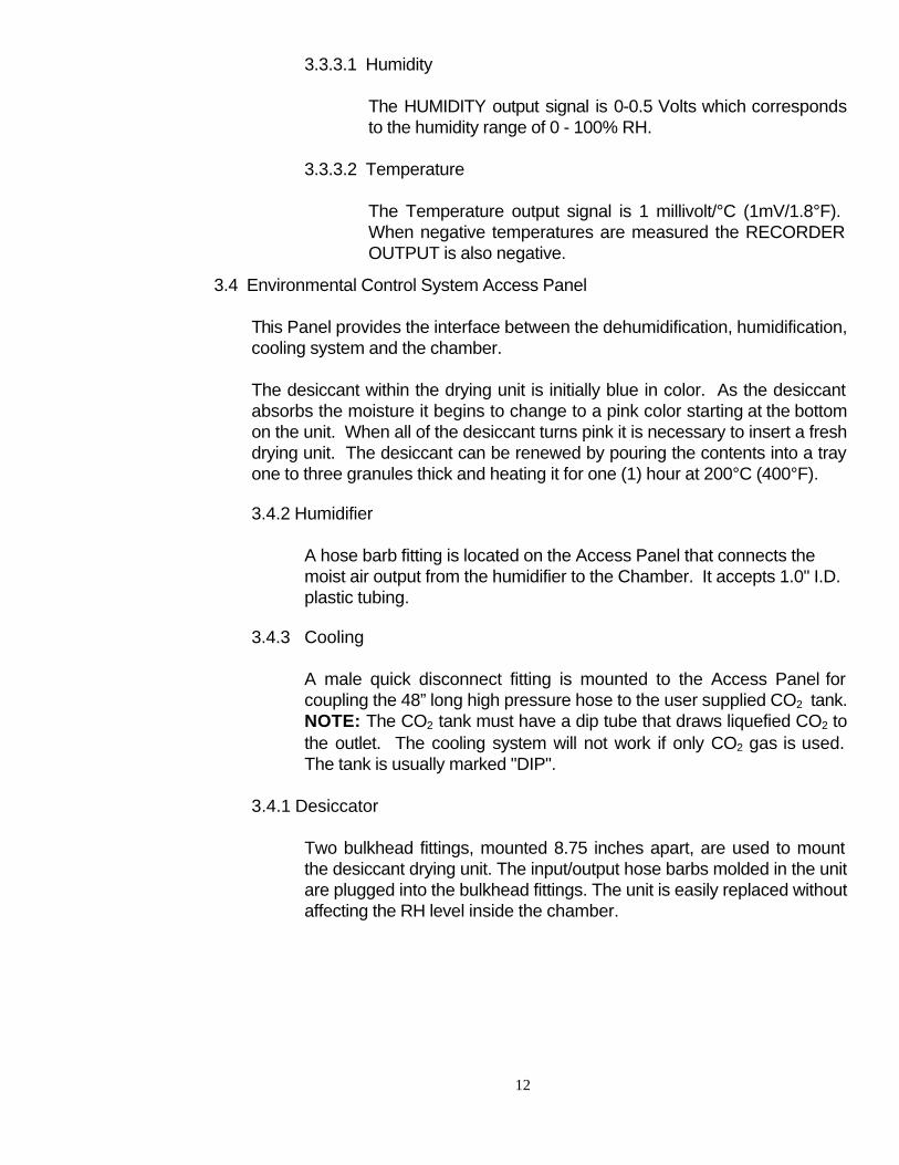
Install the high-pressure hose to the Access Panel. Install the other end to the CO2 tank as shown in Figure 4.1-1. Make certain all connections are tight since pressures up to 1,000 psi are present. Open the valve on the tank approximately ½ turn. For this application a pressure regulator is not necessary.
Figure 4.1.1-1 Cooling System Installation 4.1.2 Humidifier
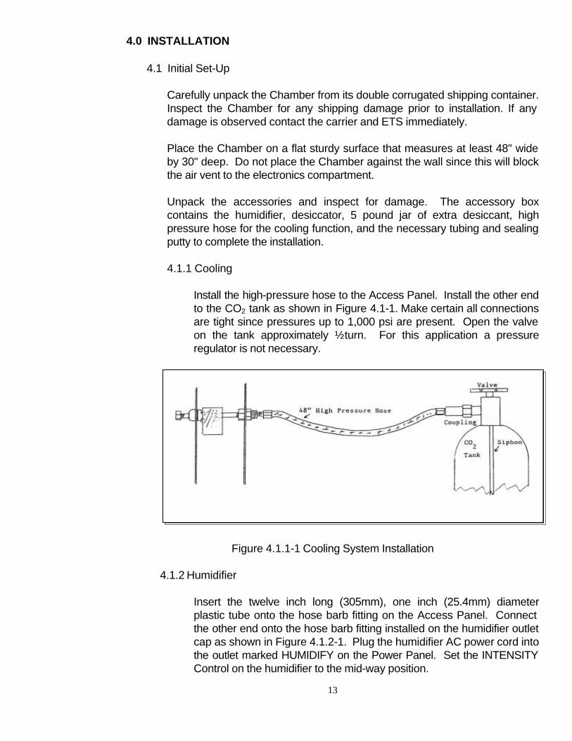
Insert the twelve inch long (305mm), one inch (25.4mm) diameter plastic tube onto the hose barb fitting on the Access Panel. Connect the other end onto the hose barb fitting installed on the humidifier outlet cap as shown in Figure 4.1.2-1. Plug the humidifier AC power cord into the outlet marked HUMIDIFY on the Power Panel. Set the INTENSITY Control on the humidifier to the mid-way position.
4.1 Initial Set-Up
14
Figure 4.1.2.1 Humidifier System Installation
Remove the water tank from the humidifier and fill it ¾ the way with DISTILLED WATER. Normal tap water contains minerals which will clog the transducer and also cause the creation of white dust in the chamber which may damage the sensors.
4.1.3 Desiccator
The last step is the installation of the desiccator unit. This unit is a plastic cylinder with an aluminum screw-on cap and two molded hose barbs. With the cap facing up, insert the hose barbs into the bulkhead fittings on the Access Panel. Tighten the fittings finger tight to secure the unit. The system is now ready for initial turn-on and check-out.
Turn on system power with the POWER switch located on the front Control Panel. The LCD displays and LED point source indicators on each of the Controller modules should light. The LCD displays will indicate the relative humidity and the temperature inside the Chamber. Turn on the LIGHT and FAN power switches. Both accessories should come on.
Next, check the operation of the Controllers. Switch the HUMIDIFY and DEHUMIDIFY and the HEAT and COOL switches to OFF. Only the green
4.2 Initial System Checkout
15
HUMIDITY and TEMP LEDs should be lit. Depress the red READ/SET paddle switch to the SET position. The green LED should turn off and the red SET PT LED should turn on. Rotate the SET ADJUST controls fully counterclockwise. The R.H. display should read 00.0 ±0.2% and the temperature display should read approximately -5.0°C (25°F). Rotate the controls fully clockwise. The displays should now read 100.00 ±0.2% and the temperature should read approximately 54°C (130°F). Release the switch. It will return to the READ position. Note the humidity and temperature readings. Depress the respective READ/SET switches and rotate the ADJUST controls until the display indicates the same humidity and temperature as the measured readings. Release the switch. Turn on the DEHUMIDIFY switch and rotate the ADJUST control slowly clockwise. The green DEHUMIDIFY LED should light and the pump inside the electronics compartment should turn on. After approximately a minute or so the HUMIDITY display should start indicating a decrease in humidity level. Turn off the DEHUMIDIFY switch and turn on the HUMIDIFY switch. Slowly rotate the ADJUST control counterclockwise until the yellow LED lights and the humidifier turns on. After several seconds the display should start indicating an increase in humidity. If the SET POINT is set approximately 1 or 2% R.H. away from the measured humidity the dehumidify and humidify control functions can be observed. Only one function should be operated at a time.
Repeat the above procedures for checking out the temperature control functions. If all functions operate correctly, the Model 518 Automatically Controlled Environmental Chamber is now ready for use.
5.0 OPERATION
Open the front door by turning the eight (8) ¾-turn latches fully counterclockwise. Place the desired instrumentation inside the chamber. If the equipment is AC powered, plug it into the grounded accessory outlet. If more than two (2) outlets are required, then a multi-outlet power strip can be installed. Do not overload the circuit. Close and seal the door by turning the screw latches clockwise. It may be necessary to push on the door slightly until the latch arm catches. Tighten the latches until an even compression of the sealing gasket is obtained.
Turn the system on with the POWER switch on the Controller front panel. 5.1 Placing Instrumentation Inside the Chamber
16
CAUTION: Do not over tighten the latches since this will compress the gasket excessively. It is recommended that AC powered instrumentation not be powered by the accessory power outlet when operating at relative humidities above 80%.
Once any large instruments or objects are installed inside the chamber, smaller test specimens or objects can be placed in the chamber through the 12” x 4” access door located on the left hand side. This door is locked in place by the three (3) ¾- turn latches.
Observe the relative humidity reading on the LCD display. If the desired humidity inside the chamber is less than the ambient level, turn the DEHUMIDIFY switch on and the HUMIDIFY switch off. Depress the READ/SET switch to SET and turn the HUM SET ADJUST control until the desired level is displayed on the meter. The green HUMIDIFY LED will light and the internal pump will turn on. As the air inside the chamber is circulated through the desiccator the humidity level will drop and the bottom of the desiccator unit will start to turn pink. The system will operate until the desired humidity level is reached. When the humidity increases above the 0.5% R.H. of the set point level the system will turn back on. The system will continue to cycle to maintain the desired humidity. It should take approximately 3 hours to decrease the humidity from 50% to 12% RH. If the desired humidity inside the chamber is greater than the ambient level, turn the HUMIDIFY switch on and the DEHUMIDIFY switch off. Follow the procedure above, but now the humidifier will turn on and off to maintain the desired humidity level. Adjust the INTENSITY Control on the humidifier for the desired humidification rate. Sliding the control down will cause the chamber to humidify slower while sliding the control up will cause the chamber to humidify more rapidly. It should take approximately 15 minutes or less to increase the humidity level from 50% to 98% RH. NOTE: If very low RH levels are desired, it is recommended that the humidifier line be disconnected from the Access Panel and the Humidify Inlet fitting be capped with the cap plug supplied.
5.3 Controlling Temperature
The procedure for selecting and maintaining a desired temperature within the range of 32 -122°F (0 - 50°C) is identical to the procedure described in Section 5.2 above. For cooling, verify that the valve on the CO2 tank has been opened approximately ½ turn.
5.2 Controlling Relative Humidity
17
The temperature can be controlled over the approximately range ±22°C (±40°F) about ambient. Normal room temperature is approximately 70°F, therefore, the range of 32 - 120°F is obtainable. On the other hand, if the ambient temperature is significantly different than 70°F, the Chamber may not be able to obtain the extremes in range. This will be especially true for reaching the maximum specified temperature at low ambient.
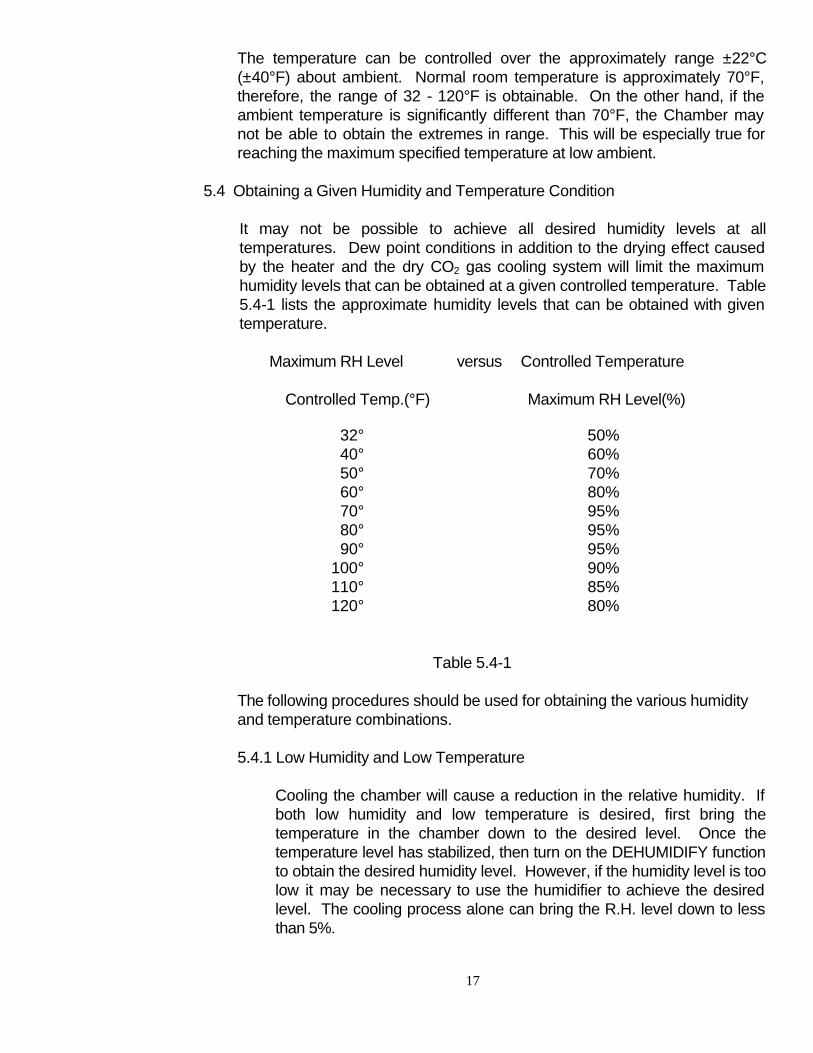
It may not be possible to achieve all desired humidity levels at all temperatures. Dew point conditions in addition to the drying effect caused by the heater and the dry CO2 gas cooling system will limit the maximum humidity levels that can be obtained at a given controlled temperature. Table 5.4-1 lists the approximate humidity levels that can be obtained with given temperature.
Maximum RH Level versus Controlled Temperature
Controlled Temp.(°F) Maximum RH Level(%)
32° 50% 40° 60% 50° 70% 60° 80% 70° 95% 80° 95% 90° 95%
100° 90% 110° 85% 120° 80%
Table 5.4-1
The following procedures should be used for obtaining the various humidity and temperature combinations.
5.4.1 Low Humidity and Low Temperature
Cooling the chamber will cause a reduction in the relative humidity. If both low humidity and low temperature is desired, first bring the temperature in the chamber down to the desired level. Once the temperature level has stabilized, then turn on the DEHUMIDIFY function to obtain the desired humidity level. However, if the humidity level is too low it may be necessary to use the humidifier to achieve the desired level. The cooling process alone can bring the R.H. level down to less than 5%.
5.4 Obtaining a Given Humidity and Temperature Condition
18
5.4.2 High Humidity and Low Temperature
To achieve these conditions first bring the temperature down to the desired level. Once the temperature level has been stabilized, then turn on the HUMIDIFY function to obtain the desired R.H. level. See Table 5.4-1.
5.4.3 Low Humidity and High Temperature
High temperatures will also reduce the humidity level inside the chamber, but not as much as with dry gas used to obtain low temperatures. Set the Temperature Controller for the desired temperature level. After the temperature inside the chamber has stabilized turn on the DEHUMIDIFY function and set the Humidity Controller for the desired humidity level. Again, it may be necessary to add humidity to achieve the desired humidity level. See Table 5.4-1.
5.4.4 High Humidity and High Temperature
Follow the procedure described in Section 5.4.2 above, except increase the TEMP level to the desired temperature. After it reaches the set point, set the Humidity Controller for the desired humidity level. See Table 5.4-1.
5.4.5 Intermediate Humidity Temperature
Follow the above procedures. First, the desired temperature is established in the chamber then the humidity is adjusted to the desired level. See Table 5.4-1. If very tight temperature control is required, turn on both the HEAT and COOL switches. This will minimize the overshoot associated with the heater, however, this procedure is not recommended since it will cause the two systems to fight each other.
5.5.1 Dehumidify
Frequent on/off cycling of the dehumidifier or humidifier may be indicative of a poor door seal or a tear in the gloves. The chamber should be thoroughly inspected to determine where the leak(s) are occurring and the problem corrected. However, other circumstances can also affect the humidity level. Water absorbing materials such as wood and paper that have been in a high humidity environment prior to being placed in the chamber may overload the dehumidification system and it may take several desiccator renewals to dry out the material and bring the chamber down to the desired level.
5.5 Maintaining Selected Humidity and Temperature Levels
19
The desiccant can only be renewed approximately ten times before having to be replaced. Worn out desiccant is indicated by the dehumidification system appearing to operate normally, but the humidity level inside the chamber fails to decrease or may even increase.
5.5.2 Humidify
If the chamber fails to humidify and the system appears to be functioning correctly, then the problem is most likely in the humidifier. First check that the tank is filled with water. If the tank is filled, then check to see if the hose connecting the humidifier to the chamber is clogged with water droplets. This is easily corrected by removing the tube and blowing out the water.
Next, remove the tank and check to see if the bottom of the humidifier is filled with water. If it is, remove the water. Refill the tank to capacity and place it back onto the humidifier base. Distilled water or water having a low mineral content (soft water) must be used. Use of ordinary tap water will result in the rapid build-up of white dust which will clog the ultrasonic transducer.
If a residue is noticed around the ultrasonic transducer it can be cleaned using a mixture of white vinegar and water (approximately one tablespoon of white vinegar to one pint of distilled water). Place the solution in the Mist Chamber and Reservoir and allow it to stand for an hour, then thoroughly rinse with clean cool water.
Refer to Section 7.2 for care and maintenance of the humidifier.
5.5.3 Cool
If the chamber fails to cool the problem is most likely an empty CO2 tank, or if it is a replacement tank, an incorrect tank type. The tank must have a siphon inside that draws the liquid CO2 and not the gas.
If the tank is full the orifice in the cooling nozzle may be clogged. A tool is provided for clear the orifice. The nozzle is the brass fitting located inside the chamber.
NOTE: When changing tanks, first shut off the main valve on the tank and then turn on the COOL switch (it may be necessary to lower the TEMP ADJUST setting so that the solenoid activates). This will release any pressure in the high pressure line.
20
6.0 CALIBRATION
The Automatic Control System incorporated into the Model 518 Controlled Environmental Chamber is calibrated prior to leaving the factory. However, as with all humidity and temperature measuring instruments, it should be recalibrated periodically to maintain its specified performance. Calibration of the System should be checked at least once or twice a year depending on the operating conditions and the required measurement accuracy. Complete calibration of the System is performed in two parts. The first part requires calibration of the Humidity and Temperature Control Units. The second part requires calibration of the humidity and temperature sensors in conjunction with the Control Units. Both the Control System and the sensors are easily removed from the Chamber by the following procedure: Open the large front door and loosen the hex cap on the bulkhead fitting holding the humidity (bottom) and the temperature (top) sensors in place. Push the sensors in towards the electronics section. Loosen the four captive fasteners securing the Control System to the Chamber. This system is a completely self-contained unit. Remove the System from the Chamber. Pull the sensors out of the bulkhead fittings and place them outside the Chamber.
Remove the four captive fasteners securing the Control System to the Chamber. This system is a completely self-contained unit. Remove the System from the Chamber. Pull the sensors out of the bulkhead fittings and place them outside the Chamber. Remove the top and bottom covers from the Control Unit. The System is now ready for calibration. A calibrated digital voltmeter (DVM) with a 0.1 millivolt resolution and a variable 1 Volt (min) DC power source are required. For calibration of humidity, a calibrated humidity measuring instrument is required.
6.1.1 Control Unit Calibration
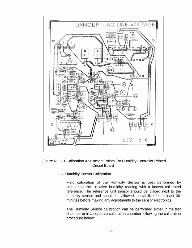
Figure 6.1.1-1 is a diagram showing the location of the calibrated adjustment points on the Control Unit printed circuit board. The procedure for calibrating the Humidity Control Unit is as follows:
1. Turn the Control System POWER switch on and the
DEHUMIDIFY and HUMIDIFY switches off.
2. Zero Offset Adjust - Rotate the HUM SET ADJ control to its fully counterclockwise position (0% R.H.). Adjust R6 so that the voltage measured at U2-6 is 0.000 ±.001 Volts. Use the + lead on C6 as a ground point.
6.1 Humidity Controller
21
3. Full Scale Calibration - Adjust the HUM SET ADJ control
to its fully clockwise position (100.0% R.H.). Adjust R4 so that the voltage measured at U2-3 is +5.00 ±.01 Volts.
4. Display 100% Point Calibration - Depress the
READ/SET switch and observe the Display reading. Adjust R28 so that the Display indicates 100.0% R.H.
5. Display 0% Point Check - Adjust the HUM SET ADJ
control to its fully counterclockwise position. Depress the READ/SET switch and observe the Display reading. It should be 000.0 ±.2% R.H.
6. Sensor Input Zero Offset Adjust - Unplug the Humidity
Sensor DIN Connector. Connect a shorting jumper between Pins 1 and 2 of the HUMIDITY SENSOR connector on the rear panel of the Control Unit. With the READ/SET switch in the READ position, adjust R3 so that the voltage measured at Pin 6 of U1 with the DVM is 0.000 ±.1mV. Remove the jumper.
7. Recorder Output Calibration - Connect the + output of the
power supply to Pin 1 of the HUMIDITY SENSOR connector and the output (or ground) side to Pin 2. Using the DVM, adjust the power supply for 1.000 ±.001V. Connect the DVM to the RECORDER output BNC connector and measure the voltage. Adjust the R12 until a reading of 0.500 ±.001V is obtained. The selector switch should be in the READ position for this test. The Display should be reading 100.0 ±.2% R.H.
8. Comparator and Humidity Readout Calibration Test -
Using the same test set-up as in Paragraph 7 above, set the power supply for an output of 0.25 ±0.1V. The Display should read 25.0 ±.2% R.H. Depress the READ/SET switch and adjust the set point to obtain the same exact reading as above. Turn on the DEHUMIDIFY and HUMIDIFY switches. Vary the HUM SET ADJ control by ±0.5% R.H. The DEHUMIDIFY and HUMIDIFY lights must turn on and off within +0.5% of the set point.
The above test can be repeated for 50.0% R.H. (0.50V) and 75.0% R.H. (0.75V) to check the calibration at these humidity points.
The above procedure completes the calibration of the Control Unit portion of the system.
22
Figure 6.1.1-1 Calibration Adjustment Points For Humidity Controller Printed Circuit Board
6.1.2 Humidity Sensor Calibration
Field calibration of the Humidity Sensor is best performed by comparing the relative humidity reading with a known calibrated reference. The reference unit sensor should be placed next to the humidity sensor and should be allowed to stabilize for at least 30 minutes before making any adjustments to the sensor electronics. The Humidity Sensor calibration can be performed either in the test chamber or in a separate calibration chamber following the calibration procedure below:
23
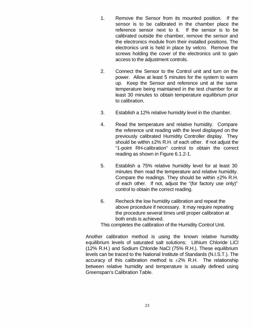
1. Remove the Sensor from its mounted position. If the sensor is to be calibrated in the chamber place the reference sensor next to it. If the sensor is to be calibrated outside the chamber, remove the sensor and the electronics module from their installed positions. The electronics unit is held in place by velcro. Remove the screws holding the cover of the electronics unit to gain access to the adjustment controls.
2. Connect the Sensor to the Control unit and turn on the
power. Allow at least 5 minutes for the system to warm up. Keep the Sensor and reference unit at the same temperature being maintained in the test chamber for at least 30 minutes to obtain temperature equilibrium prior to calibration.
3. Establish a 12% relative humidity level in the chamber. 4. Read the temperature and relative humidity. Compare
the reference unit reading with the level displayed on the previously calibrated Humidity Controller display. They should be within ±2% R.H. of each other. If not adjust the “1-point RH-calibration” control to obtain the correct reading as shown in Figure 6.1.2-1.
5. Establish a 75% relative humidity level for at least 30
minutes then read the temperature and relative humidity. Compare the readings. They should be within ±2% R.H. of each other. If not, adjust the “(for factory use only)” control to obtain the correct reading.
6. Recheck the low humidity calibration and repeat the
above procedure if necessary. It may require repeating the procedure several times until proper calibration at both ends is achieved.
This completes the calibration of the Humidity Control Unit. Another calibration method is using the known relative humidity equilibrium levels of saturated salt solutions; Lithium Chloride LiCl (12% R.H.) and Sodium Chloride NaCl (75% R.H.). These equilibrium levels can be traced to the National Institute of Standards (N.I.S.T.). The accuracy of this calibration method is ±2% R.H. The relationship between relative humidity and temperature is usually defined using Greenspan’s Calibration Table.
24
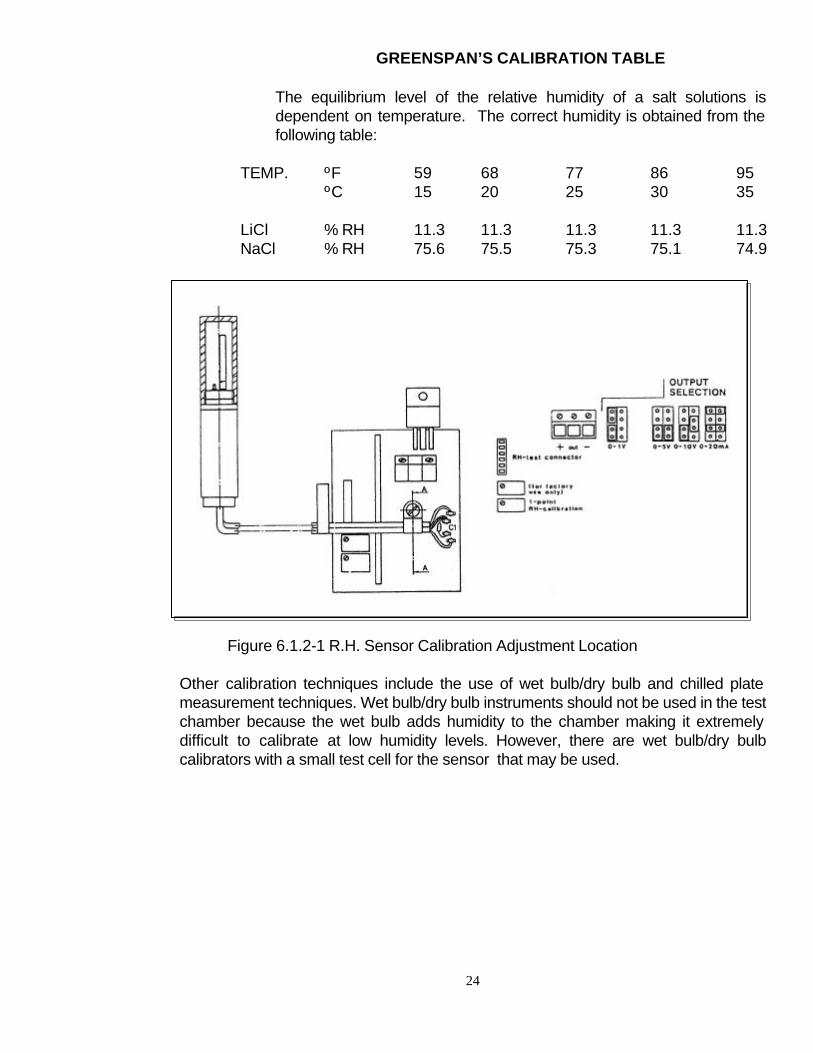
GREENSPAN’S CALIBRATION TABLE The equilibrium level of the relative humidity of a salt solutions is dependent on temperature. The correct humidity is obtained from the following table:
TEMP. ºF 59 68 77 86 95 ºC 15 20 25 30 35 LiCl % RH 11.3 11.3 11.3 11.3 11.3 NaCl % RH 75.6 75.5 75.3 75.1 74.9
Figure 6.1.2-1 R.H. Sensor Calibration Adjustment Location
Other calibration techniques include the use of wet bulb/dry bulb and chilled plate measurement techniques. Wet bulb/dry bulb instruments should not be used in the test chamber because the wet bulb adds humidity to the chamber making it extremely difficult to calibrate at low humidity levels. However, there are wet bulb/dry bulb calibrators with a small test cell for the sensor that may be used.
25
6.2 Temperature Controller
6.2.1 Control Unit Calibration
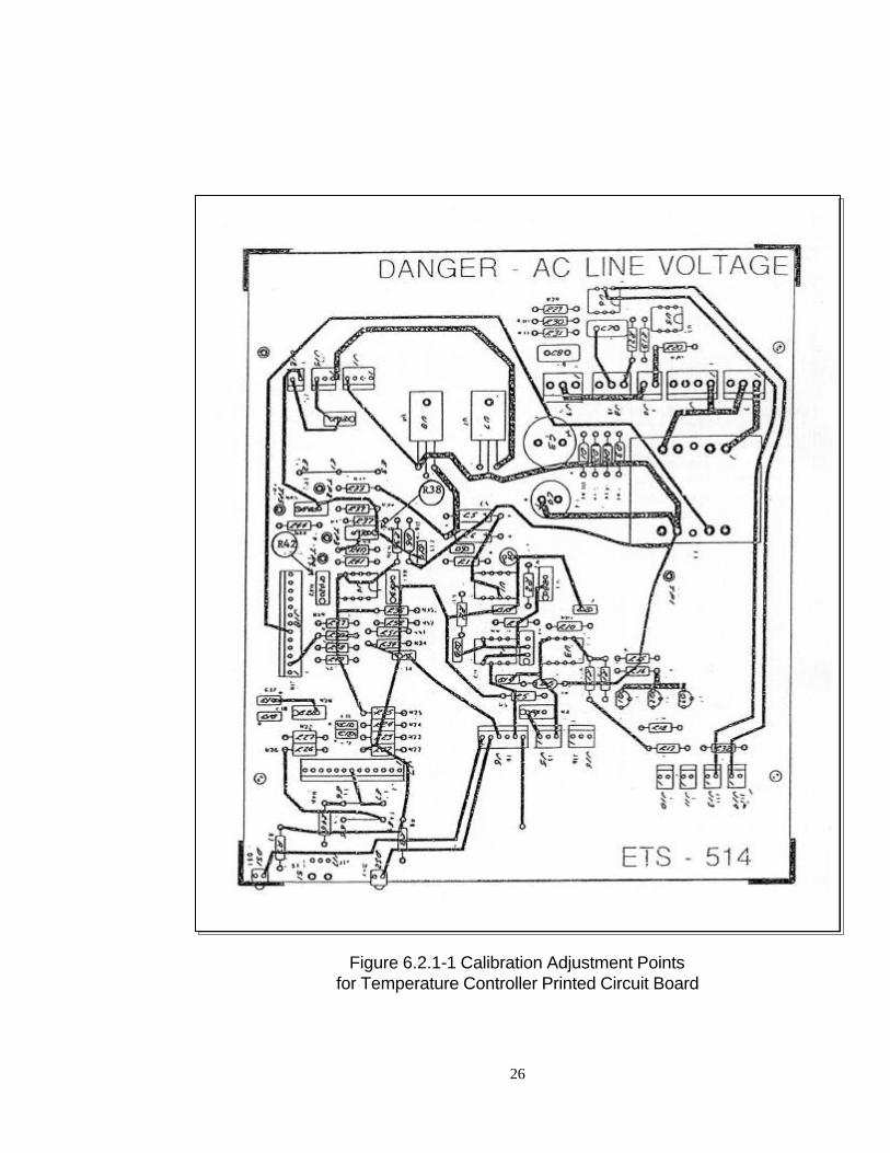
Figure 6.2.1-1 is a diagram showing the location of the calibration adjustment points on the Controller printed circuit board The procedure for calibrating the Temperature Control Unit is as follows:
°C Calibration - Connect the power source of Pin #1 to the SENSOR connector. Adjust the output for 0.000 Volts. Set the °C/°F switch on the front panel to the °C position. The LCD Display should read 0.0 ±0.1°C.
Adjust the power supply for 1.400 ±.001 Volts. The LCD Display should read 140.0 ±0.1°C. If not, adjust R45 until the correct reading is obtained.
°F Calibration - Set the °C/°F switch on the front panel to the °F position. Adjust the power source for 0.000 Volts. The LCD Display should read 32.0 ±0.1°F. If not, adjust R38 until the correct reading is obtained.
Adjust the power source for 0.600 ±.001 Volts. Adjust R42 for an LCD Display reading of 140.0 ±0.1°F. It will be necessary to go back and readjust R38 and R42 several times to obtain the correct readings at 32° and 140°F. Recorder Output Calibration - Connect the + output of the power supply to Pin 1 of the Temperature Sensor connector and the -output (or ground) side to Pin 2. Using the DVM, adjust the power supply for 1.000 ±.001v. Connect the DVM to the RECORDER output BNC connector and measure the voltage. Adjust R12 until a reading of 1.000 ±.001V is obtained. The selector switch should be in the READ position for this test. The Display should read 100.0 ±.1°C. The above procedure completes the calibration of the Control Unit portion of the system.
6.2.2 Temperature Sensor Calibration
The Temperature Sensor is a solid state device that is calibrated for an output of 10 mV/°C. No external adjustments are available.
26
Figure 6.2.1-1 Calibration Adjustment Points
for Temperature Controller Printed Circuit Board
27
7.0 MAINTENANCE
7.1 Desiccator
Remove the desiccator from the Access Panel. Remove the aluminum cap and the felt filter, then pour the contents into a tray. The granules should be spread evenly, one or two deep. The desiccant should be heated for approximately one (1) hour at approximately 400 °F (200 °C) then allowed to air cool in the oven or an air tight container before refilling the acrylic drying unit. The felt filters should also be dried out approximately 200 °F (100 °C) for thirty (30) minutes before assembly. The desiccant can be renewed approximately ten (10) times before having to be replaced. When the dehumidification system is unable to reduce the humidity in the chamber, and the desiccant has just been renewed, this indicates that its drying properties have been exhausted and must be replaced.
7.2 Ultrasonic Humidifier
For the Ultrasonic Humidifier to maintain peak performance it must cleaned and rinsed on a periodic basis. Ordinary tap water contains chemicals and minerals that affect the operation of Ultrasonic Humidifiers. Use of distilled or demineralized water will reduce the white dust that occurs with the ultrasonic breakup of water molecules. The following cleaning procedure should be followed to ensure proper operation of the unit:
7.2.1 Cleaning
1. Always unplug the unit before cleaning.
2. Lift out the Water Tank.
3. Clean the surface of the Transducer and Water Sensor with a soft, clean cloth and a small amount of white vinegar after every use, or sooner, if mineral deposits are noticed. Rinse with water and gently wipe with a soft, clean damp cloth.
Do not use any tools with metal parts to clean the Transducer surface.
Proper maintenance of the Model 518 Automatically Controlled Environmental Chamber will ensure continuous, reliable operation. Section 6.0 describes the calibration procedure for the humidity and temperature control systems. This section covers the procedure for renewing the desiccant, servicing the humidifier, and replacing the 15 Watt fluorescent lamp in the accessory lighting fixture.
28
In areas where hard water is a problem, clean accumulated deposits by placing three (3) ounces of white vinegar in the Transducer area. Let stand for thirty (30) minutes to soften any mineral deposits. Gently clean the Transducer with a soft brush. Discard the vinegar, rinse with water and wipe gently with a soft, clean, damp cloth.
Before filling the Water Tank and when the humidifier will be stored or not used for an extended period of time, rinse the inside of the Tank and Base with lukewarm water and wipe with a clean, damp cloth. Make sure the unit is thoroughly dry before storing. Repeat this procedure before putting the humidifier back into use.
4. Never immerse the humidifier.
5. Do not allow water to enter the air outlet or any other openings. IMPORTANT: Use extreme care when handling the Water Tank for filling or cleaning. Do not jar or damage the water valve and do not cross thread the Tank Cap.
6. Carefully clean any accumulated deposits from the surface of
Ultrasonic Transducer (white metal disc). Do not put undue pressure on the Transducer.
7. Do not clean any part of the humidifier with gasoline, kerosene,
glass or furniture polish, thinner or water hotter than 120 °F.
CAUTION: When the unit is not in use, do not leave water in the Water Tank or Base. This may result in the buildup of material deposits and bacteria that may inhibit the effective use of the unit.
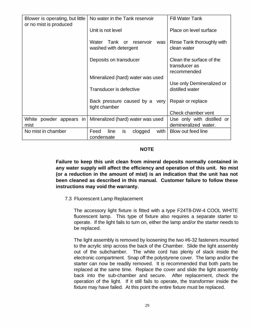
7.2.2 Trouble Shooting Guide
If the humidifier is not working properly, check the following points:
TROUBLE CAUSE REMEDY No Power
Unit not plugged in Controller HUMIDIFY switch not on.
Plug unit in Turn on HUMIDIFY switch
LED lamp does not glow
Power failure Blown fuse
Power is restored Return unit to factory
29
Blower is operating, but little or no mist is produced
No water in the Tank reservoir Unit is not level Water Tank or reservoir was washed with detergent Deposits on transducer Mineralized (hard) water was used Transducer is defective Back pressure caused by a very tight chamber
Fill Water Tank Place on level surface Rinse Tank thoroughly with clean water Clean the surface of the transducer as recommended Use only Demineralized or distilled water Repair or replace Check chamber vent
White powder appears in mist
Mineralized (hard) water was used
Use only with distilled or demineralized water.
No mist in chamber Feed line is clogged with condensate
Blow out feed line
NOTE
Failure to keep this unit clean from mineral deposits normally contained in any water supply will affect the efficiency and operation of this unit. No mist (or a reduction in the amount of mist) is an indication that the unit has not been cleaned as described in this manual. Customer failure to follow these instructions may void the warranty.
The accessory light fixture is fitted with a type F24T8-DW-4 COOL WHITE fluorescent lamp. This type of fixture also requires a separate starter to operate. If the light fails to turn on, either the lamp and/or the starter needs to be replaced. The light assembly is removed by loosening the two #6-32 fasteners mounted to the acrylic strip across the back of the Chamber. Slide the light assembly out of the subchamber. The white cord has plenty of slack inside the electronic compartment. Snap off the polystyrene cover. The lamp and/or the starter can now be readily removed. It is recommended that both parts be replaced at the same time. Replace the cover and slide the light assembly back into the sub-chamber and secure. After replacement, check the operation of the light. If it still fails to operate, the transformer inside the fixture may have failed. At this point the entire fixture must be replaced.
7.3 Fluorescent Lamp Replacement
30
8.0 TROUBLE SHOOTING
1. No Power - Check Controller fuse (½ amp at 115 VAC, ¼ amp at 230
VAC). Check power at wall outlet.
2. Power (LEDs light), but no indication on LCD Display - LCD Display defective or no ±5 VDC. Return unit to factory.
3. Obviously Incorrect Humidity Readings - Blow gently onto Humidity
Sensor and observe reading. If small (±10% R.H.) changes in humidity are observed, the Humidity Sensor is at least working. Depress the READ/SET switch and adjust the HUM SET ADJ control fully counterclockwise and then rotate it fully clockwise. The Display should show readings of 00.0 ±.2% R.H. to 100.0 ±.2% R.H. If not, proceed to Paragraph 4.
To check the sensor input circuit to the Control Unit, connect a 1.00 Volt power source between Pin 1 (+) and Pin 2 (-) of the HUMIDITY SENSOR IN connector. With a voltmeter, also measure the voltage between Pins 3 (+) and 2 of the Humidity Sensor. It should measure approximately 22 Volts.
Proper display and voltage readings indicate that the problem is in the Sensor Unit or cable. The Sensor must be returned to the factory for service.
If the correct voltage is measured, but the Display gives an erroneous reading, replace U1 (Harris CA3140) in the Control Unit.
4. Incorrect RH Set-Point Readings - With a voltmeter, check the voltages
at U1. At Pin 4, the voltage measured should be -11.4 to -12.6 Volts and at Pin 7 it should be +11.4 to +12.6 Volts. If either voltage is out of specification, return the unit to the factory for service.
If the voltage checks okay, replace U2 (LM741 or equivalent). If the unit still fails to operate, return it to the factory.
If the Model 518 Automatically Controlled Environmental Chamber fails to function properly, first check the respective accessories (desiccant, humidifier, and CO2 gas tank). The electronic control system is solid state and should provide many years of trouble-free service. If a problem in the Control System is suspected it is recommended that the fault be initially isolated to either the Sensor or to the respective Control Unit. If the problem is with both Control Units, contact ETS before proceeding. Otherwise, the following trouble shooting guide should help in locating the more obvious problems.
8.1 Humidity Control System
31
5. No DEHUMIDIFY and/or HUMIDIFY AC Control Voltage -Turn on the DEHUMIDIFY and HUMIDIFY switches. Read the humidity level on the LCD display, then adjust the set-point to that level. Rotate the control at least ±.05% R.H. about this point. The Green DEHUMIDIFY indicator should come on when the set point is below the measured humidity and the Yellow HUMIDIFY indicator should be off. When the set point is above the measured humidity the Green indicator should turn off and the Yellow indicator should turn on. If the lights cycle but the dehumidifier and/or humidifier fail to operate then the respective fuses may be blown or the dehumidifier and/or humidifier systems may have failed.
After checking the fuses and the system still fails to operate, the unit must be returned to the factory for repair.
If any components are replaced, it will be necessary to recalibrate the system as set forth in Section 6.1.
1. No Power - Check Controller fuse (½ amp at 115 VAC, ¼ amp at 230
VAC). Check power at wall outlet.
2. Power (LEDs light), but no indication on LCD Display - LCD Display defective or no ±5 VDC. Return unit to factory.
3. Incorrect Temperature Readings - Place the temperature sensor in
the hand and hold it tightly for several seconds and observe the reading. If a small change in temperature is observed, the Temperature Sensor is at least working. Depress the READ/SET switch and adjust the TEMP SET ADJ control fully counterclockwise and then rotate fully clockwise. The Display should show readings of 0°C to 50°C ±.1°C. If not, proceed to Paragraph 4.
To check the sensor input circuit to the Controller, connect a 1 ±.001 Volt power source between Pin 1 (+) and Pin 2 (-) of the TEMPERATURE SENSOR IN connector. The LCD display should read 100 ±.1°C. Then with a voltmeter, measure the voltage between Pins 3 (+) and 2 (-). It should measure approximately 22 volts. Proper display and voltage readings indicate that the problem is in the Sensor Unit or cable. The Sensor must be returned to the factory for service. If the correct voltage is measured, but the Display gives an erroneous reading, replace U1 (Harris CA3140) in the Control Unit.
4. Incorrect TEMP Set-Point Readings - With a voltmeter, check the voltages at U1. At Pin 4, the voltage measured should be -11.4 to -12.6 Volts and at Pin 7 it should be +11.4 to +12.6 Volts. If either
8.2 Temperature Control System
32
voltage is out of specification, return the unit to the factory for service.
If the voltage checks okay, replace U2 (LM741 or equivalent). If the unit still fails to operate, return it to the factory.
5. No COOL and/or HEAT Control Voltage - Turn on the COOL and
HEAT switches. Read the temperature level on the LCD display, then adjust the set-point to that level. Rotate the control at least 5°C about this point. The Green COOL indicator should come on when the set point is below the measured temperature and the Yellow HEAT indicator should be off. When the set point is above the measured temperature the Green indicator should turn off and the Yellow indicator should turn on. If the lights cycle but the cooling and/or heating fail to operate then the respective fuses may be blown or the cooling and/or heating systems may have failed.
After checking the fuses and the system still fails to operate, the unit must be returned to the factory for repair.
If any components are replaced, it will be necessary to recalibrate the system as forth in Section 6.2.
2/8/99
33
WARRANTY
Electro-Tech Systems, Inc. warrants its equipment, accessories and parts of its manufacture to be and remain free from defects in material and workmanship for a period of one (1) year from date of invoice and will, at the discretion of Seller, either replace or repair without charge, F.O.B. Glenside, similar equipment or a similar part to replace any equipment or part of its manufacture which, within the above stated time, is proved to have been defective at the time it was sold. All equipment claimed defective must be returned properly identified to the Seller (or presented to one of its agents for inspection). This warranty only applies to equipment operated in accordance with Seller's operating instructions. Seller's warranty with respect to those parts of the equipment which are purchased from other manufacturers shall be subject only to that manufacturer's warranty. The Seller's liability hereunder is expressly limited to repairing or replacing any parts of the equipment manufactured by the manufacturer and found to have been defective. The Seller shall not be liable for damage resulting or claimed to result from any cause whatsoever. This warranty becomes null and void should the equipment, or any part thereof, be abused or modified by the customer of if used in any application other than that for which it was intended. This warranty to replace or repair is the only warranty, either expressed or implied or provided by law, and is in lieu of all other warranties and the Seller denies any other promise, guarantee, or warranty with respect to the equipment or accessories and, in particular, as to its or their suitability for the purposes of the buyer or its or their performance, either quantitatively or qualitatively or as to the products which it may produce and the buyer is expected to expressly waive rights to any warranty other than that stated herein. ETS must be notified before any equipment is returned for repair. ETS will issue an RMA (Return Material Authorization) number for return of equipment. Equipment should be shipped prepaid and insured in the original packaging. If the original packaging is not available, the equipment must be packed in a sufficiently large box (or boxes if applicable) of double wall construction with substantial packing around all sides. The RMA number, description of the problem along with the contact name and telephone number must be included in formal paperwork and enclosed with the instrument. Round trip freight and related charges are the owner’s responsibility.
WARNING WOODEN CRATES MUST NOT BE USED. PACKAGING OF DELICATE INSTRUMENTS IN WOODEN CRATES SUBSTANTIALLY INCREASES THE CONTENT’S SUSCEPTIBILITY TO SHOCK DAMAGE. DO NOT PLACE INSTRUMENTS OR ACCESSORIES INSIDE OTHER INSTRUMENTS OR CHAMBERS. ELECTRO-TECH SYSTEMS, INC. WILL NOT ASSUME RESPONSIBILITY FOR ADDITIONAL COST OF REPAIR DUE TO DAMAGE INCURRED DURING SHIPMENT AS A RESULT OF POOR PACKAGING.