Embed Size (px)
Citation preview
Copyright © 2002 Control Technology Corporation
All Rights Reserved.
Printed in USA
TM
Model 5100 Series Automation
Controller Installation Guide
Doc. No. 5100IG
Revision C
April 2002
Control Technology Corporation proprietary. Reproduction or distribution forbidden.
The information in this document is subject to change without notice. The software described in this
document is provided under license agreement and may be used or copied only in accordance with the
terms of the license agreement.
The information, drawings, and illustrations contained herein are the property of Control Technology
Corporation. No part of this manual may be reproduced or distributed by any means, electronic or
mechanical, for any purpose other than the purchaser’s personal use, without the express written consent of
Control Technology Corporation.
The following are trademarks of Control Technology Corporation:
• Quickstep
• CTC Monitor
• CTC Utilities
Windows is a trademark of Microsoft Corporation.
iii
Control Technology Corporation proprietary. Reproduction or distribution forbidden.
Notes to Readers ................................................................................................. 1
Related Documents ........................................................................................ 2
Formatting Conventions ................................................................................. 2
Contacting Control Technology Corporation .................................................. 3
Your Comments ............................................................................................. 3
System Overview ................................................................................................. 5
Easy Installation ............................................................................................. 5
Ethernet Connectivity ..................................................................................... 5
I/O, Motion Control, and UI Integration ........................................................... 5
Dimensions and Mounting Considerations ........................................................... 6
Model 5100 Description ........................................................................................ 9
Wiring Diagrams ................................................................................................. 10
Specifications ..................................................................................................... 12
Connecting Power to the Controller ................................................................... 16
The Importance of Proper Grounding ........................................................... 16
The Controller’s Power System .................................................................... 16
Using External Power Supplies .................................................................... 16
Status Light Description ..................................................................................... 17
Software Fault .............................................................................................. 17
Hardware Fault ............................................................................................. 17
Computer – Controller Communications ............................................................ 18
RS-232 Communications ............................................................................. 18
RS-232 Connections .................................................................................... 18
Connecting to a D Connector ....................................................................... 19
Using Ethernet for Controller Communications ............................................ 20
Ethernet Protocol .......................................................................................... 20
10Base-T .......................................................................................... 20
100Base-T (Fast Ethernet) ............................................................... 20
Network Specifications ..................................................................... 20
Host Communications ...................................................................... 21
Contents

Contents
iv
Control Technology Corporation proprietary. Reproduction or distribution forbidden.
This page is intentionally left blank.
1
Control Technology Corporation proprietary. Reproduction or distribution forbidden.
The Model 5100 Installation Guide provides the following information:
• System Overview – describes the various 5100 configurations.
• Dimensions and Mounting Considerations – mounting dimensions and precautions on
mounting the 5100.
• CPU Description – provides details on the faceplate and describes the
distribution board and how it connects to the CPU.
• Wiring Diagrams – pinout diagrams for the various connectors residing on the
distribution board and on the CPU; on-board I/O mapping information.
• Specifications – general and electrical specifications; hardware and firmware revisions
for the 5100.
• Power Connections – connecting power to the controller.
• Status Lights – how the status lights function.
• Computer – Controller Connections – describes the controller’s RS-232 ports and
Ethernet port.
Notes to Readers
2
Control Technology Corporation proprietary. Reproduction or distribution forbidden.
Notes to Readers
Related Documents
The following documents contain additional information:
• For information on Quickstep, refer to the QuickstepTM Language and Programming Guide
or the QuickstepTM User Guide.
• For information on the controller registers, refer to the Register Reference Guide
(available at www.ctc-control.com).
• For information on Microsoft Windows or the PC, refer to the manuals provided by the
vendor.
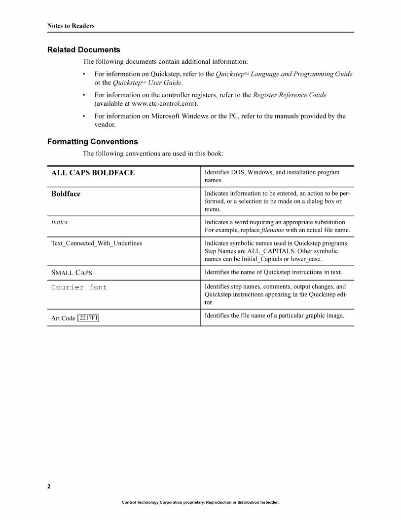
Formatting Conventions
The following conventions are used in this book:
ALL CAPS BOLDFACE Identifies DOS, Windows, and installation program
names.
Boldface Indicates information to be entered, an action to be per-
formed, or a selection to be made on a dialog box or
menu.
Italics Indicates a word requiring an appropriate substitution.
For example, replace filename with an actual file name.
Text_Connected_With_Underlines Indicates symbolic names used in Quickstep programs.
Step Names are ALL_CAPITALS. Other symbolic
names can be Initial_Capitals or lower_case.
SMALL CAPS Identifies the name of Quickstep instructions in text.
Courier font Identifies step names, comments, output changes, and
Quickstep instructions appearing in the Quickstep edi-
tor.
Art Code Identifies the file name of a particular graphic image.2217F12217F1
3
Control Technology Corporation proprietary. Reproduction or distribution forbidden.
Model 5100 Automation Controller Installation Guide
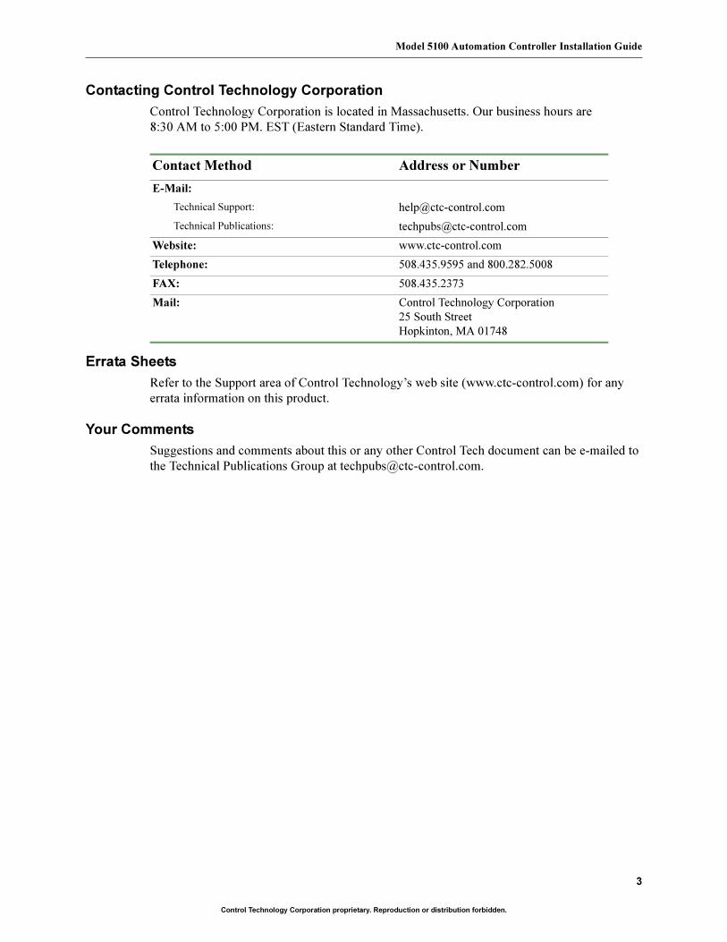
Contacting Control Technology Corporation
Control Technology Corporation is located in Massachusetts. Our business hours are
8:30 AM to 5:00 PM. EST (Eastern Standard Time).
Errata Sheets
Refer to the Support area of Control Technology’s web site (www.ctc-control.com) for any
errata information on this product.
Your Comments
Suggestions and comments about this or any other Control Tech document can be e-mailed to
the Technical Publications Group at [email protected].
Contact Method Address or Number
E-Mail:
Technical Support: [email protected]
Technical Publications: [email protected]
Website: www.ctc-control.com
Telephone: 508.435.9595 and 800.282.5008
FAX: 508.435.2373
Mail: Control Technology Corporation
25 South Street
Hopkinton, MA 01748

4
Control Technology Corporation proprietary. Reproduction or distribution forbidden.
Notes to Readers
This page is intentionally left blank.
5
Model 5100 Automation Controller Installation Guide
Control Technology Corporation proprietary. Reproduction or distribution forbidden.
System Overview
The Model 5100 Series is part of Control Technology Corporation’s Blue Fusion family of
automation controllers and is available in multiple configurations. Its flexible architecture can
accommodate up to 6 modules in its internal module bays. Analog and digital I/O modules fit
into a single bay and motion control modules require two bays.
Note
Modules are only installed during the controller fabrication process and are not configurable in
the field.
Easy Installation
The 5100’s compact footprint (8.3" x 5.7") allows it to easily fit into cramped system designs.
You can snap it onto a DIN rail or use optional mounting ears to install it on a flat surface such
as a NEMA-rated electrical enclosure. Pluggable terminal blocks ease repetitive wiring duties
by providing a quick disconnect.
Ethernet Connectivity
A built-in 10/100Base-T Ethernet connector supports various network protocols (TCP/IP,
UDP, CTNET, and ModBus TCP) and puts your devices on the Web over secure connections.
Refer to Wiring Diagrams for information on how this connector is wired.
I/O, Motion Control, and UI Integration
The 5100 can integrate digital and analog I/O points and up to 6.5 axes of servo or stepper
control. Its two serial ports are available for HMIs (human-machine interfaces), programming
interfaces, or other serial devices.
Program the 5100 controller with CTC’s state programming language, Quickstep™ for Win-
dows™. You can run all programming and diagnostic functions for the controller from your
PC with an RS-232 interface or Ethernet communications.
The 2-axis servo motion controller provides precise control of two servo motors by adding a
high-performance motion coprocessor in each module. Servo position loop rates are main-
tained at 250 µs per axis with encoder feedback rates up to 6 MHz without impacting other
controller operations. Each module also contains two high-speed inputs that latch encoder
position within 1 encoder count for precise registration. Axes can operate independently or can
be electronically geared to other axes or the master encoder within the 5100 controller. The
servo motion controller also interfaces directly with velocity or torque drives through
16-bit ± 10 V commands.
Control Technology Corporation
6
Control Technology Corporation proprietary. Reproduction or distribution forbidden.
Dimensions and Mounting Considerations
The Model 5100 Automation Controller can be mounted by snapping it onto a DIN rail
or by using the mounting ears to install it on a flat surface such as a NEMA-rated electrical
enclosure. Figures 1 and 2 show the controller’s dimensions. Select a mounting location that
protects against the environmental hazards listed below:
• Avoid flying metal chips that may result from installation or subsequent machine con-
struction. Avoid conductive dusts, liquids, or condensing humidity. If any of these
conditions exist, mount the 5100 in a NEMA 4 or NEMA 12 rated enclosure.
• Do not mount the 5100 in an environment that requires explosion proof practices.
• Avoid mounting locations that are in close proximity to devices that produce electro-
magnetic interference (EMI) or radio frequency interference (RFI). Devices such as
motor starters, relays, large power transformers, and ultrasonic welding apparatus fall
into this category.
7
Model 5100 Automation Controller Installation Guide
Control Technology Corporation proprietary. Reproduction or distribution forbidden.
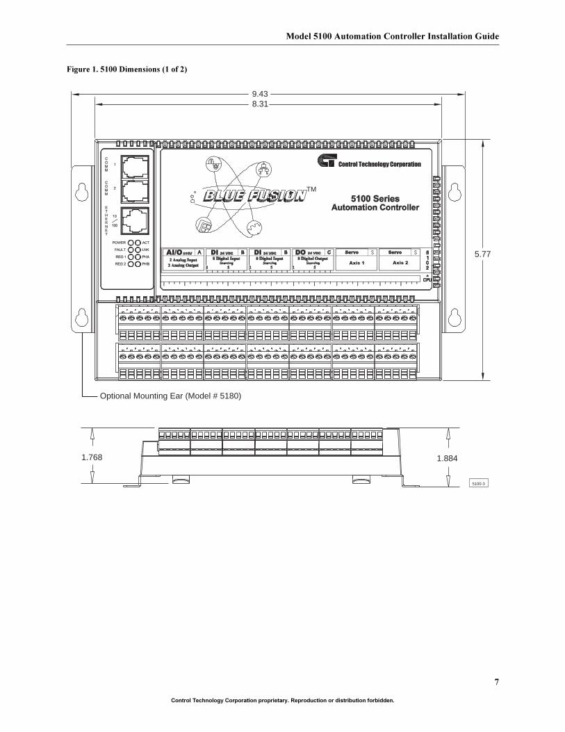
Figure 1. 5100 Dimensions (1 of 2)
9.438.31
5100-3
1.768 1.884
5.77
TM
Optional Mounting Ear (Model # 5180)
Control Technology Corporation
Axis 1 Axis 2
Control Technology Corporation
8
Control Technology Corporation proprietary. Reproduction or distribution forbidden.
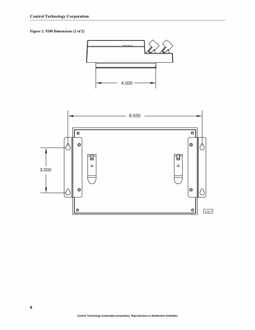
Figure 2. 5100 Dimensions (2 of 2)
4.000
8.930
3.000
5100-7
9
Model 5100 Automation Controller Installation Guide
Control Technology Corporation proprietary. Reproduction or distribution forbidden.
Model 5100 Description
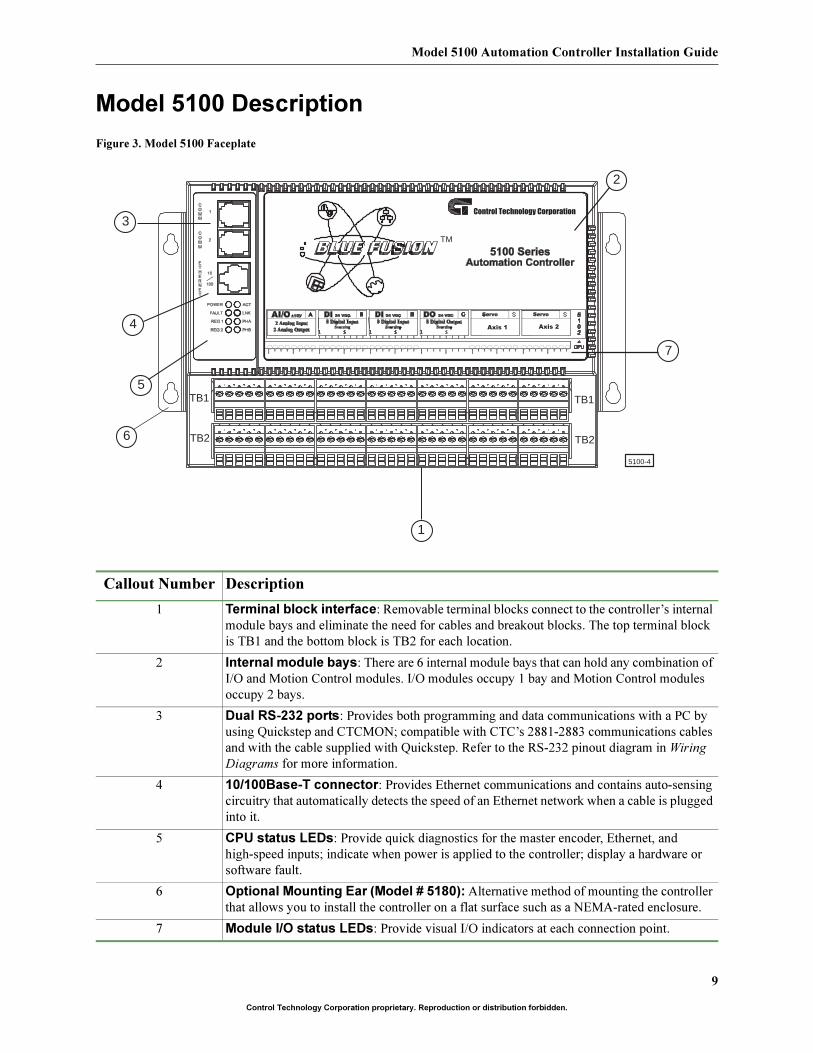
Figure 3. Model 5100 Faceplate
Callout Number Description
1 Terminal block interface: Removable terminal blocks connect to the controller’s internal
module bays and eliminate the need for cables and breakout blocks. The top terminal block
is TB1 and the bottom block is TB2 for each location.
2 Internal module bays: There are 6 internal module bays that can hold any combination of
I/O and Motion Control modules. I/O modules occupy 1 bay and Motion Control modules
occupy 2 bays.
3 Dual RS-232 ports: Provides both programming and data communications with a PC by
using Quickstep and CTCMON; compatible with CTC’s 2881-2883 communications cables
and with the cable supplied with Quickstep. Refer to the RS-232 pinout diagram in Wiring
Diagrams for more information.
4 10/100Base-T connector: Provides Ethernet communications and contains auto-sensing
circuitry that automatically detects the speed of an Ethernet network when a cable is plugged
into it.
5 CPU status LEDs: Provide quick diagnostics for the master encoder, Ethernet, and
high-speed inputs; indicate when power is applied to the controller; display a hardware or
software fault.
6 Optional Mounting Ear (Model # 5180): Alternative method of mounting the controller
that allows you to install the controller on a flat surface such as a NEMA-rated enclosure.
7 Module I/O status LEDs: Provide visual I/O indicators at each connection point.
5100-4
1
2
7
3
4
5
6
TB1
TB2
TB1
TB2
Control Technology Corporation
TM
Axis 1 Axis 2
Control Technology Corporation
10
Control Technology Corporation proprietary. Reproduction or distribution forbidden.
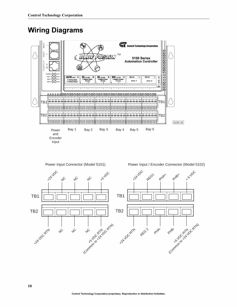
Wiring Diagrams
5100-18
Powerand
EncoderInput
Bay 1 Bay 2 Bay 3 Bay 4 Bay 5 Bay 6
TB1
TB2
TB1
TB2
TB1
+24 V
DC
REG1
PHA+PHB+
+ 5 V
DC
TB2
+24 V
DC RTN
REG 2PHA-
PHB-
TB1
+24 V
DC
NC NC NC +5 V
DC
TB2
+24 V
DC RTN NC NC NC
+5 V
DC RTN
(Com
mon
to +
24 V
DC RTN)
Power Input Connector (Model 5101) Power Input / Encoder Connector (Model 5102)
Control Technology Corporation
TM
Axis 1 Axis 2
+5 V
DC RTN
(Com
mon
to +
24 V
DC RTN)
11
Model 5100 Automation Controller Installation Guide
Control Technology Corporation proprietary. Reproduction or distribution forbidden.
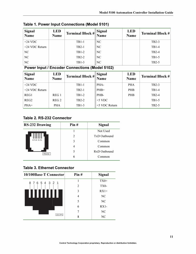
Table 1. Power Input Connections (Model 5101)
Signal
Name
LED
NameTerminal Block #
Signal
Name
LED
NameTerminal Block #
+24 VDC TB1-1 NC TB2-3
+24 VDC Return TB2-1 NC TB1-4
NC TB1-2 NC TB2-4
NC TB2-2 NC TB1-5
NC TB1-3 NC TB2-5
Power Input / Encoder Connections (Model 5102)
Signal
Name
LED
NameTerminal Block #
Signal
Name
LED
NameTerminal Block #
+24 VDC TB1-1 PHA- PHA TB2-3
+24 VDC Return TB2-1 PHB+ PHB TB1-4
REG1 REG 1 TB1-2 PHB- PHB TB2-4
REG2 REG 2 TB2-2 +5 VDC TB1-5
PHA+ PHA TB1-3 +5 VDC Return TB2-5
Table 2. RS-232 Connector
RS-232 Drawing Pin # Signal
1 Not Used
2 TxD Outbound
3 Common
4 Common
5 RxD Outbound
6 Common
Table 3. Ethernet Connector
10/100Base-T Connector Pin # Signal
1 TX0+
2 TX0-
3 RX1+
4 NC
5 NC
6 RX1-
7 NC
8 NC
16 5 4 3 2
RS232
12345678
2217P1
Control Technology Corporation
12
Control Technology Corporation proprietary. Reproduction or distribution forbidden.
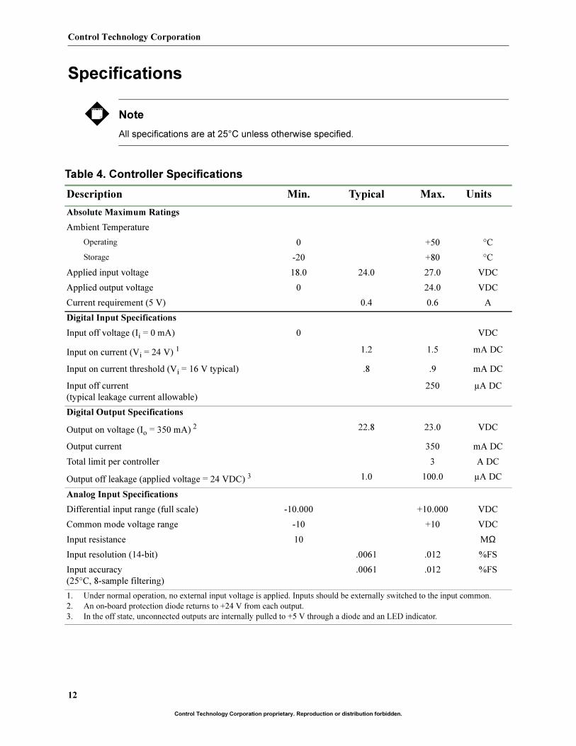
Specifications
Note
All specifications are at 25°C unless otherwise specified.
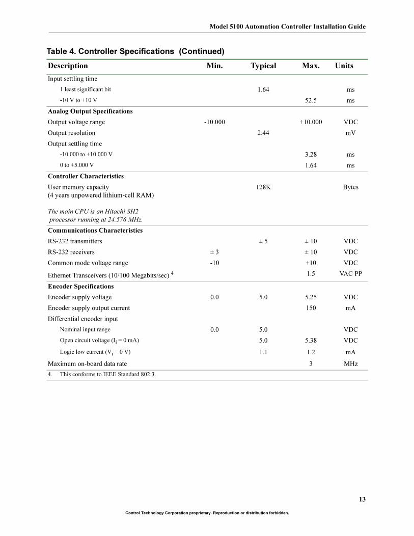
Table 4. Controller Specifications
Description Min. Typical Max. Units
Absolute Maximum Ratings
Ambient Temperature
Operating 0 +50 °C
Storage -20 +80 °C
Applied input voltage 18.0 24.0 27.0 VDC
Applied output voltage 0 24.0 VDC
Current requirement (5 V) 0.4 0.6 A
Digital Input Specifications
Input off voltage (Ii = 0 mA) 0 VDC
Input on current (Vi = 24 V) 1 1.2 1.5 mA DC
Input on current threshold (Vi = 16 V typical) .8 .9 mA DC
Input off current
(typical leakage current allowable)
250 µA DC
Digital Output Specifications
Output on voltage (Io = 350 mA) 2 22.8 23.0 VDC
Output current 350 mA DC
Total limit per controller 3 A DC
Output off leakage (applied voltage = 24 VDC) 3 1.0 100.0 µA DC
Analog Input Specifications
Differential input range (full scale) -10.000 +10.000 VDC
Common mode voltage range -10 +10 VDC
Input resistance 10 MΩInput resolution (14-bit) .0061 .012 %FS
Input accuracy
(25°C, 8-sample filtering)
.0061 .012 %FS
1. Under normal operation, no external input voltage is applied. Inputs should be externally switched to the input common.
2. An on-board protection diode returns to +24 V from each output.
3. In the off state, unconnected outputs are internally pulled to +5 V through a diode and an LED indicator.
13
Model 5100 Automation Controller Installation Guide
Control Technology Corporation proprietary. Reproduction or distribution forbidden.
Input settling time
1 least significant bit 1.64 ms
-10 V to +10 V 52.5 ms
Analog Output Specifications
Output voltage range -10.000 +10.000 VDC
Output resolution 2.44 mV
Output settling time
-10.000 to +10.000 V 3.28 ms
0 to +5.000 V 1.64 ms
Controller Characteristics
User memory capacity
(4 years unpowered lithium-cell RAM)
The main CPU is an Hitachi SH2
processor running at 24.576 MHz.
128K Bytes
Communications Characteristics
RS-232 transmitters ± 5 ± 10 VDC
RS-232 receivers ± 3 ± 10 VDC
Common mode voltage range -10 +10 VDC
Ethernet Transceivers (10/100 Megabits/sec) 4 1.5 VAC PP
Encoder Specifications
Encoder supply voltage 0.0 5.0 5.25 VDC
Encoder supply output current 150 mA
Differential encoder input
Nominal input range 0.0 5.0 VDC
Open circuit voltage (Ii = 0 mA) 5.0 5.38 VDC
Logic low current (Vi = 0 V) 1.1 1.2 mA
Maximum on-board data rate 3 MHz
4. This conforms to IEEE Standard 802.3.
Table 4. Controller Specifications (Continued)
Description Min. Typical Max. Units
Control Technology Corporation
14
Control Technology Corporation proprietary. Reproduction or distribution forbidden.
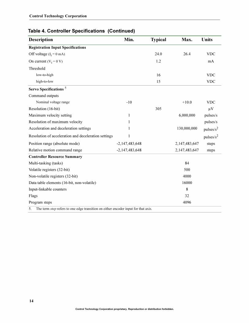
Registration Input Specifications
Off voltage (Ii = 0 mA) 24.0 26.4 VDC
On current (Vi = 0 V) 1.2 mA
Threshold
low-to-high 16 VDC
high-to-low 15 VDC
Servo Specifications 5
Command outputs
Nominal voltage range -10 +10.0 VDC
Resolution (16-bit) 305 µV
Maximum velocity setting 1 6,000,000 pulses/s
Resolution of maximum velocity 1 pulses/s
Acceleration and deceleration settings 1 130,000,000 pulses/s2
Resolution of acceleration and deceleration settings 1 pulses/s2
Position range (absolute mode) -2,147,483,648 2,147,483,647 steps
Relative motion command range -2,147,483,648 2,147,483,647 steps
Controller Resource Summary
Multi-tasking (tasks) 84
Volatile registers (32-bit) 500
Non-volatile registers (32-bit) 4000
Data table elements (16-bit, non-volatile) 16000
Input-linkable counters 8
Flags 32
Program steps 4096
5. The term step refers to one edge transition on either encoder input for that axis.
Table 4. Controller Specifications (Continued)
Description Min. Typical Max. Units
15
Model 5100 Automation Controller Installation Guide
Control Technology Corporation proprietary. Reproduction or distribution forbidden.
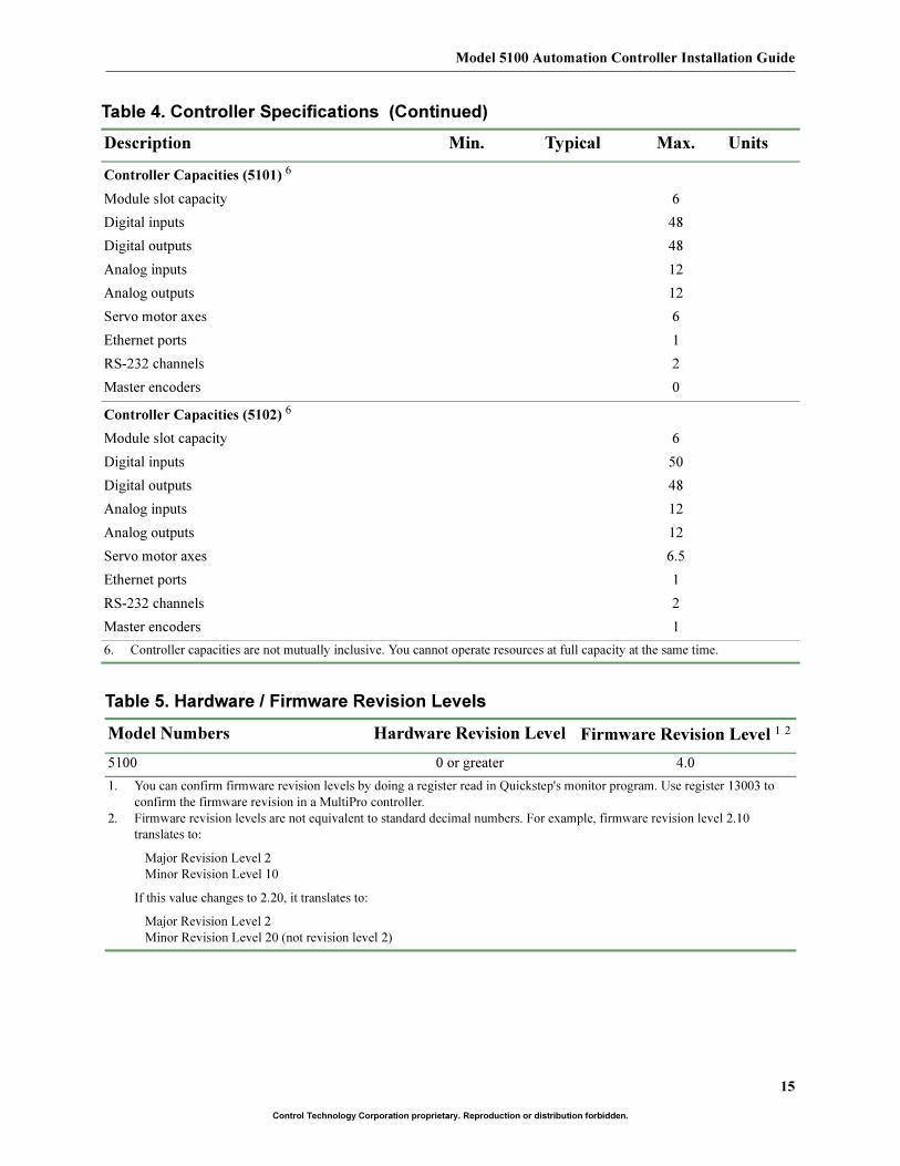
Controller Capacities (5101) 6
Module slot capacity 6
Digital inputs 48
Digital outputs 48
Analog inputs 12
Analog outputs 12
Servo motor axes 6
Ethernet ports 1
RS-232 channels 2
Master encoders 0
Controller Capacities (5102) 6
Module slot capacity 6
Digital inputs 50
Digital outputs 48
Analog inputs 12
Analog outputs 12
Servo motor axes 6.5
Ethernet ports 1
RS-232 channels 2
Master encoders 1
6. Controller capacities are not mutually inclusive. You cannot operate resources at full capacity at the same time.
Table 5. Hardware / Firmware Revision Levels
Model Numbers Hardware Revision Level Firmware Revision Level 1 2
5100 0 or greater 4.0
1. You can confirm firmware revision levels by doing a register read in Quickstep's monitor program. Use register 13003 to
confirm the firmware revision in a MultiPro controller.
2. Firmware revision levels are not equivalent to standard decimal numbers. For example, firmware revision level 2.10
translates to:
Major Revision Level 2
Minor Revision Level 10
If this value changes to 2.20, it translates to:
Major Revision Level 2
Minor Revision Level 20 (not revision level 2)
Table 4. Controller Specifications (Continued)
Description Min. Typical Max. Units
Control Technology Corporation
16
Control Technology Corporation proprietary. Reproduction or distribution forbidden.
Connecting Power to the Controller
This section provides general guidelines on connecting power to the 5100 controller.
The Importance of Proper Grounding
As with any electronic equipment, the controller’s ground should follow a direct, low-imped-
ance path to the plant’s power source. If possible, this path should not be shared by any
machinery which injects a large amount of electrical noise into the ground.
For further consideration regarding noise protection, refer to Technical Note No. 26, Reducing
Noise Susceptibility, which is available in the Customer Support area of our web site at
www.ctc-control.com.
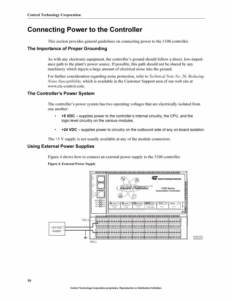
The Controller’s Power System
The controller’s power system has two operating voltages that are electrically isolated from
one another:
• +5 VDC – supplies power to the controller’s internal circuitry, the CPU, and the
logic-level circuitry on the various modules.
• +24 VDC – supplies power to circuitry on the outbound side of any on-board isolation.
The +5 V supply is not usually available at any of the module connectors.
Using External Power Supplies
Figure 4 shows how to connect an external power supply to the 5100 controller.
Figure 4. External Power Supply
Automation Controller
5100 Series
Control Technology Corporation
B B C A S SDI 24 VDC
8 Digital InputSourcing
1 5
DI 24 VDC
8 Digital InputSourcing
51
24 VDCDO
8 Digital OutputSourcing
1 5
2 Analog Input
AI/O ±10V
2 Analog Output
Servo
Axis 1
Servo
Axis 2
5100-13
TM
TB2-1
TB1-1
+_
+24 VDCSupply
17
Model 5100 Automation Controller Installation Guide
Control Technology Corporation proprietary. Reproduction or distribution forbidden.
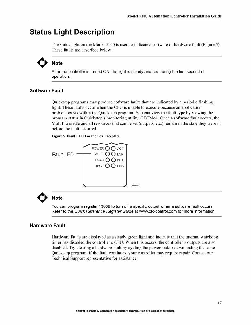
Status Light Description
The status light on the Model 5100 is used to indicate a software or hardware fault (Figure 5).
These faults are described below.
Note
After the controller is turned ON, the light is steady and red during the first second of
operation.
Software Fault
Quickstep programs may produce software faults that are indicated by a periodic flashing
light. These faults occur when the CPU is unable to execute because an application
problem exists within the Quickstep program. You can view the fault type by viewing the
program status in Quickstep’s monitoring utility, CTCMon. Once a software fault occurs, the
MultiPro is idle and all resources that can be set (outputs, etc.) remain in the state they were in
before the fault occurred.
Figure 5. Fault LED Location on Faceplate
Note
You can program register 13009 to turn off a specific output when a software fault occurs.
Refer to the Quick Reference Register Guide at www.ctc-control.com for more information.
Hardware Fault
Hardware faults are displayed as a steady green light and indicate that the internal watchdog
timer has disabled the controller’s CPU. When this occurs, the controller’s outputs are also
disabled. Try clearing a hardware fault by cycling the power and/or downloading the same
Quickstep program. If the fault continues, your controller may require repair. Contact our
Technical Support representative for assistance.
5100-8
POWER
FAULT
REG1
REG2
ACT
LNK
PHA
PHB
Fault LED
Control Technology Corporation
18
Control Technology Corporation proprietary. Reproduction or distribution forbidden.
Computer – Controller Communications
The controller can communicate with a computer or with other controllers through one of its
RS-232 ports or through its Ethernet connector.
RS-232 Communications
The controller’s RS-232 ports allow the following activities:
• Direct communications between a PC and the controller - This feature enables
you to directly interact with many of the controller’s resources such as registers,
inputs, outputs, and flags without modifying the controller’s program.
• Monitoring - You can monitor a controller’s activity through an RS-232 port with
CTCMON.
• Host configuration - The 5100 is configurable as a host that can support
communications with other external peripherals such as operator interface terminals,
bar-code readers, printers, and other controllers. Refer to Technote No. 30, ASCII
Message Transmitting with CTC Controllers, which is available in the Support section
of our web site at www.ctc-control.com.
Note
For more information on data communications and the DLL functions required to communicate
with the controller, refer to the CTC 32-Bit Data Communications Functions Reference Guide,
which is available in the Support area of our web site at www.ctc-control.com.
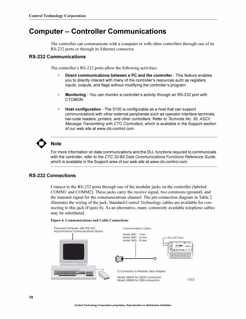
RS-232 Connections
Connect to the RS-232 ports through one of the modular jacks on the controller (labeled
COMM1 and COMM2). These jacks carry the receive signal, two commons (ground), and
the transmit signal for the communications channel. The pin connection diagram in Table 2
illustrates the wiring of the jack. Standard Control Technology cables are available for con-
necting to this jack (Figure 6). As an alternative, many commonly available telephone cables
may be substituted.
Figure 6. Communications and Cable Connections
Communications Cables:
Model 2881 - 7 feetModel 2882 - 15 feetModel 2883 - 25 feet
Personal Computer with RS-232 Asynchronous Communications Board
D-Connector to Modular Jack Adapter:
Model 2880A for DB25 connectorsModel 2880B for DB9 connectors
RS-232 Ports
5100-9
TM
Control Technology Corporation
Axis 1 Axis 2
19
Model 5100 Automation Controller Installation Guide
Control Technology Corporation proprietary. Reproduction or distribution forbidden.
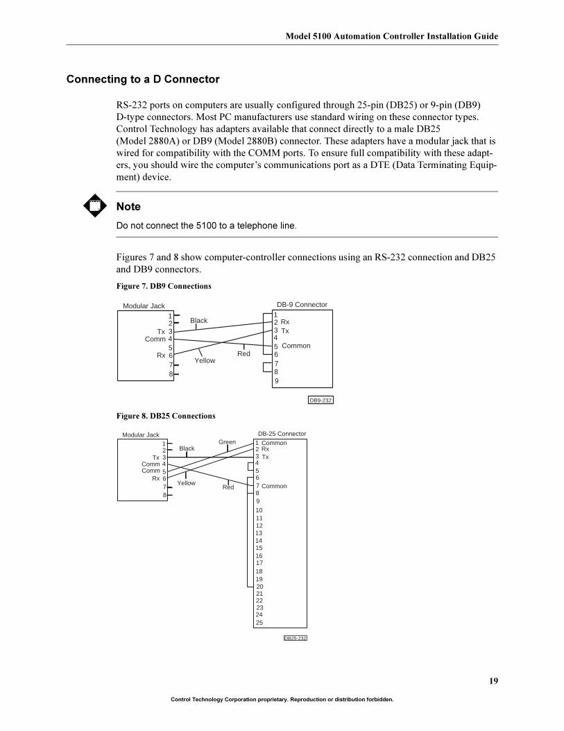
Connecting to a D Connector
RS-232 ports on computers are usually configured through 25-pin (DB25) or 9-pin (DB9)
D-type connectors. Most PC manufacturers use standard wiring on these connector types.
Control Technology has adapters available that connect directly to a male DB25
(Model 2880A) or DB9 (Model 2880B) connector. These adapters have a modular jack that is
wired for compatibility with the COMM ports. To ensure full compatibility with these adapt-
ers, you should wire the computer’s communications port as a DTE (Data Terminating Equip-
ment) device.
Note
Do not connect the 5100 to a telephone line.
Figures 7 and 8 show computer-controller connections using an RS-232 connection and DB25
and DB9 connectors.
Figure 7. DB9 Connections
Figure 8. DB25 Connections
12345678
TxComm
Rx
123456789
RxTx
Modular Jack DB-9 Connector
Black
YellowRed
Common
DB9-232
12345678
TxComm
Rx
123456789
RxTx
Modular Jack DB-25 Connector
Black
YellowRed Common
DB25-232
10111213141516171819202122232425
Common
Comm
Green
Control Technology Corporation
20
Control Technology Corporation proprietary. Reproduction or distribution forbidden.
Using Ethernet for Controller Communications
The 5100 has a 10/100Base-T connector that conforms to IEEE standard 802.3. This section
discusses the Ethernet protocol and illustrates a typical network configuration. Wiring infor-
mation for the Ethernet connector is listed in Table 3 and performance specifications are listed
in Table 4.
Ethernet Protocol
Ethernet is defined by the IEEE 802.3 standard and is the most widely used local area network
(LAN) access method. Data packets are transmitted over twisted pair cable using the carrier
sense multiple access with collision detection (CSMA/CD) algorithm until they arrive at their
destination without any collisions. Ethernet nodes on a segment share the bandwidth, which is
10 MBps (Ethernet), 100 MBps (Fast Ethernet), or 1000 MBps (Gigabit Ethernet). The 5100
module has an Ethernet port that allows it to communicate over an Ethernet network using
10Base-T or 100Base-T connections. Auto-sensing circuitry automatically detects the trans-
mission rate on the network when a cable is plugged into the port.
10Base-T
This connection type uses unshielded twisted pair (UTP) cabling and standard RJ-45 connec-
tors. 10Base-T uses Category 3 (or higher) cables. Higher category numbers provide greater
protection from outside electrical interference. CTC recommends using Category 5 UTP
cable.
100Base-T (Fast Ethernet)
Fast Ethernet (IEEE 802.3u) is traditional CSMA/CD at 100 MBps over UTP cables.
Because its design is based on the 10Base-T standard, it can be easily incorporated into exist-
ing networks. Three media types are supported:
• 100Base-TX - 2 pairs of Category 5 UTP cable and an RJ-45 connector.
• 100Base-T4 - 4 pairs of Category 3-5 UTP cable.
• 100Base-FX - multimode fiber-optic cable; primarily used on backbones.
Because 100Base-TX resembles 10Base-T so closely, it is the most popular type of Fast
Ethernet connection.
Network Specifications
Node and cable specifications for 10Base-T and 100Base-T connections are listed below.
Termination for 10/100Base-T is provided by a hub. The total nodes per hub are determined by
the hub size.
Total number of nodes supported: 32767
Maximum number of nodes per segment: 1024
Maximum cable length per segment: 100 meters
Maximum cable length per network: 500 meters (10Base-T)
200-250 meters (100Base-T)
21
Model 5100 Automation Controller Installation Guide
Control Technology Corporation proprietary. Reproduction or distribution forbidden.
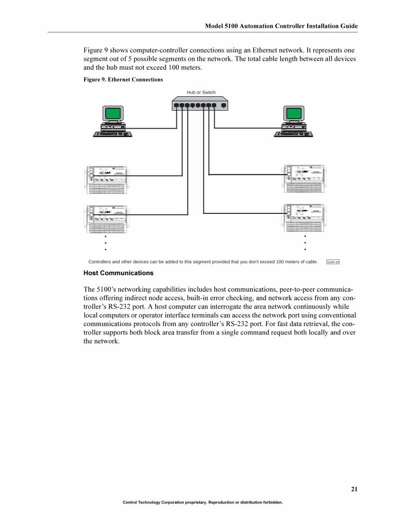
Figure 9 shows computer-controller connections using an Ethernet network. It represents one
segment out of 5 possible segments on the network. The total cable length between all devices
and the hub must not exceed 100 meters.
Figure 9. Ethernet Connections
Host Communications
The 5100’s networking capabilities includes host communications, peer-to-peer communica-
tions offering indirect node access, built-in error checking, and network access from any con-
troller’s RS-232 port. A host computer can interrogate the area network continuously while
local computers or operator interface terminals can access the network port using conventional
communications protocols from any controller’s RS-232 port. For fast data retrieval, the con-
troller supports both block area transfer from a single command request both locally and over
the network.
Hub or Switch
•••
•••
Controllers and other devices can be added to this segment provided that you don't exceed 100 meters of cable. 5100-10
TM
Control Technology Corporation
Axis 1 Axis 2
TM
Control Technology Corporation
Axis 1 Axis 2
TM
Control Technology Corporation
Axis 1 Axis 2
TM
Control Technology Corporation
Axis 1 Axis 2
Control Technology Corporation
22
Control Technology Corporation proprietary. Reproduction or distribution forbidden.
This page is intentionally left blank.