Embed Size (px)
Citation preview

Copyright © 2010 Land Instruments International
Operation and Maintenance Manual
Revision 3, October 2009Publication Nº 770.084
Part Nº198.052 Language: English
Model 4500Premier


Equipment OperationUse of this instrument in a manner not specified by Land Instruments International may be hazardous.
Electrical Power SupplyBefore working on the electrical connections all of the electrical power lines to the equipment must be isolated. All the electrical cables and signal cables must be connected exactly as indicated in these operating instructions. If in doubt contact Land Instruments International.
Face and Eye ProtectionSuitable face and eye protection must be worn when working on hot vessels and ducts! Special safety measures must be taken when working on a high-pressure duct.
Protective ClothingProtective clothing must always be worn when working in the vicinity of hot vessels or ducts.
StorageThe instrument should be stored in its packaging, in a dry sheltered area.
UnpackingCheck all packages for external signs of damage. Check the contents against the packing note.
Return of Damaged Goods
IMPORTANTIf any item has been damaged in transit, this should be reported to the carrier and to the supplier immediately. Damage caused in transit is the responsibility of the carrier not the supplier.
DO NOT RETURN a damaged instrument to the sender as the carrier will not then consider a claim. Save the packing with the damaged article for inspection by the carrier.
Return of Goods for RepairIf you need to return goods for repair please contact our Customer Service Department. They will be able to advise you on the correct returns procedure.
Any item returned to Land Instruments International should be adequately packaged to prevent damage during transit.
You must include a written report of the problem together with your own name and contact information, address, telephone number, email address etc.
Return of Goods for Repair Form is available for download from our websites.
Lifting InstructionsWhere items are too heavy to be lifted manually, use suitably rated lifting equipment. Refer to the Technical Specification for weights. All lifting should be done as stated in local regulations.
Design and Manufacturing Standards
The Quality Management System of Land Instruments International is approved to BS EN ISO 9001 for the design, manufacture and on-site servicing of combustion, environmental monitoring and non-contact temperature measuring instrumentation.
Approvals apply in the USA
This instrument complies with current European directives relating to Electromagnetic Compatibility 89/336/EEC and Low Voltage Directive 73/23/EEC.
The Quality Management System of Ametek Motors (Shanghai) Co. Limited is approved to ISO9001:2008 for the Design and Manufacturing of Motors and the Manufacturing of Gas Analysers
Operation of radio transmitters, telephones or other electrical/electronic devices in close proximity to the equipment while the enclosure doors of the instrument or its peripherals are open, may cause interference and possible failure where the radiated emissions exceed the EMC directive.
The protection provided by both CE and IP classifications to this product may be invalidated if alterations or additions are made to the structural, electrical, mechanical or pneumatic parts of this system. Such changes may also invalidate the standard terms of warranty.
Dimensions Unless otherwise stated, all measurements are given in millimetres and inches.
Signs and Symbols Used onEquipment and Documentation
Observe precautions for handling electrostatic discharge sensitive devices.
Protective Conductor Terminal.
This item or material must be disposed of in accordance with the Waste Electrical and Electronic Equipment directive as applied by local regulations.
This item or material can be recycled.
Caution, hot surface.
Caution, attention to possibility of risk of damage to the product, process or surroundings. Refer to instruction manual.
Caution, risk of electric shock.
Office Locations
UK - DronfieldTel: +44 (0) 1246 417691E-Mail: [email protected]: www.landinst.com
USA - PittsburghAMETEK Land, Inc.Tel: +1 412 826 4444E-Mail: [email protected]: www.ametek-land.com
For further details on all LAND/Ametek offices, distributors and representatives, please visit our websites.
Important Health and Safety Information
IMPORTANT INFORMATION - PLEASE READ
An Company
Copyright
This manual is provided as an aid to owners of Land Instruments International’s products and contains information proprietary to Land Instruments International. This manual may not, in whole or part, be copied, or reproduced without the expressed written consent of Land Instruments International Ltd.
Copyright © 2007 - 2011 Land Instruments International.

REV 3 publication number 770.084
Contents
Ref. Description Page
Design and Manufacturing Standards 5
Signs and Symbols Used on Equipment and Documentation 5
INSTALLATION
Ref. Description Page
A1 General Description 11
A2 Installation Diagram 13
A3 Installation Instructions 14A3-1 Installation Checklist 14A3-2 Selecting an Installation Location 15A3-3 Maintaining the Measurement Pathlength During Installation 16A3-4 Installing the Mounting Flanges 16A3-5 Mounting Details 18A3-6 Using the Flange Alignment Tool 19A3-7 Important Information for Installing the Transceiver and Retro-Reflection 20A3-8 Mounting the Transceiver and Retro-Reflector 21A3-9 Installing the Termination Box 22A3-10 Electrical Connections 23A3-11 Cable Specification 24A3-12 Termination Box Connections 25A3-13 Control Room Unit Connections 26A3-14 MODBUS Connections 27
OPERATION
Ref. Description Page
B1 Getting Started 29B1-1 The User Interface 29B1-2 Function Keys 30B1-3 Glossary of Terms 31B1-4 Using the Instrument for the First Time 32
B2 Normal Modes of Operation 48B2-1 Alarm Setup 48B2-2 Output Setup 50B2-3 MODBUS Communications 55
B3 Periodic Modes of Operation 64B3-1 Calibration Check 64B3.2 Calibration Audit 65B3-3 Re-calibration 67B3-4 Isokinetic Calibration 68B3-5 M203 Clear Stack Simulator 72B3-6 M203 Clear Stack Simulator Calibration 77B3-7 Zero Point Reflector Adjustment 80B3-8 Upscale Span Filter Adjustment 84
REFERENCE
Ref. Description Page
C1 Theory of Operation and Application 87C1-1 General Outline 87C1-2 Beer-Lambert’s Law 88C1-3 Optical Pathlength Ratio (OPLR) 89C1-4 Examples of Different Optical Pathlength Ratios (OPLR) 91
C2 Requirements for Environmental Legislation 92
C3 Physical Principles 93C3-1 General Description 93C3-2 Principle of Operation 94
C4 User Interface 96C4-1 Operational Structure 96C4-2 Faults Screens 97C4-3 Calibration Screens 98C4-4 Setup Screens 104C4-5 Display Screens 118C4-6 Parameter Screens 120
C5 System Specification 121C5-1 4500 Premier Dust and Opacity Monitor 121
C6 Testing and Checking 124C6-1 Identifying Faults 124C6-2 Maintenance 126C6-3 Replacement Parts and Consumables 130
C7 Configuration Record Sheet 134
APPENDIX
Appendix A Aperture and Grating Selection Tables 137AppA-1 Automatic Zero Point Reflector Aperture and Grating Selection 137AppA-2 Span Filter Grating Selection 137
Appendix B Low Temperature Termination Box 138AppB-1 Termination Box Heater Unit 138
STANDARD TERMS OF WARRANTY

Model 4500 Premier Dust and Opacity Monitor
11
A1 General Description
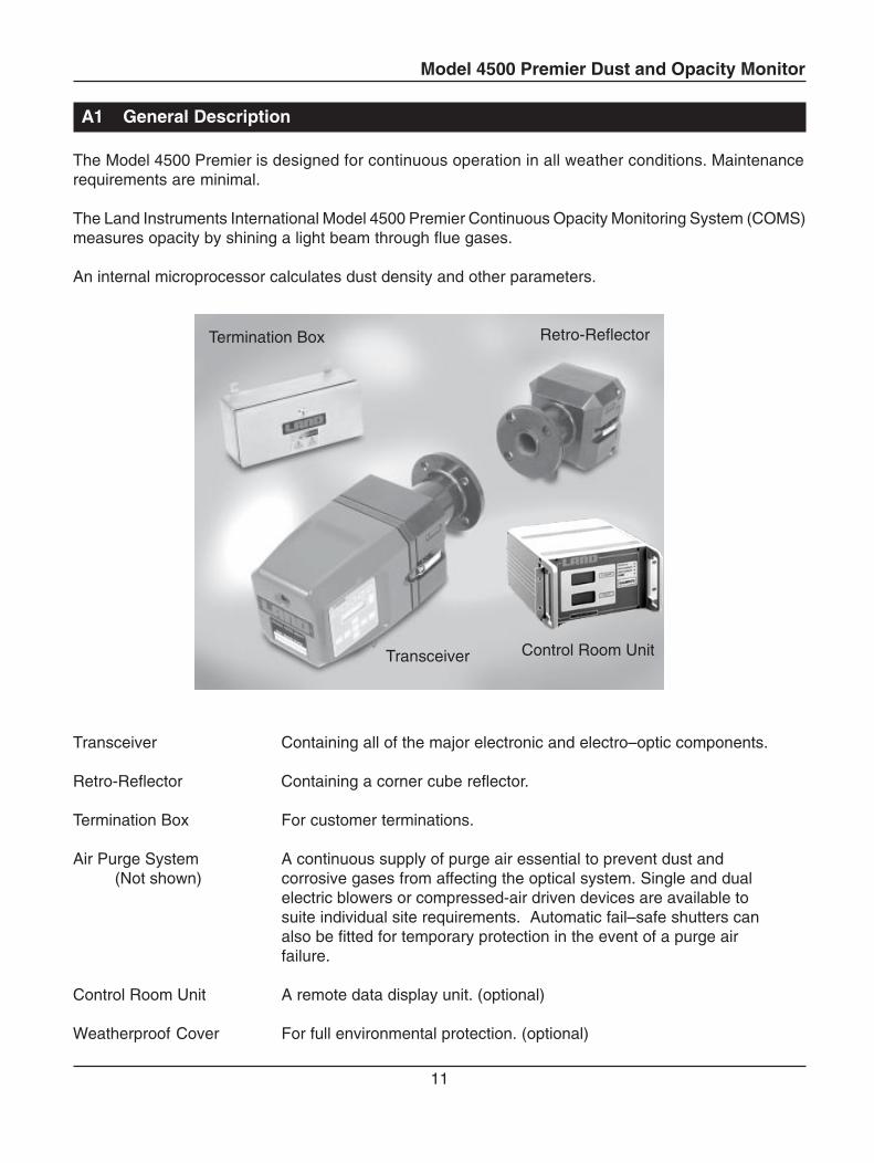
The Model 4500 Premier is designed for continuous operation in all weather conditions. Maintenancerequirements are minimal.
The Land Instruments International Model 4500 Premier Continuous Opacity Monitoring System (COMS)measures opacity by shining a light beam through flue gases.
An internal microprocessor calculates dust density and other parameters.
Transceiver Containing all of the major electronic and electro–optic components.
Retro-Reflector Containing a corner cube reflector.
Termination Box For customer terminations.
Air Purge System A continuous supply of purge air essential to prevent dust and(Not shown) corrosive gases from affecting the optical system. Single and dual
electric blowers or compressed-air driven devices are available tosuite individual site requirements. Automatic fail–safe shutters canalso be fitted for temporary protection in the event of a purge airfailure.
Control Room Unit A remote data display unit. (optional)
Weatherproof Cover For full environmental protection. (optional)
Control Room Unit
Retro-ReflectorTermination Box
Transceiver
Model 4500 Premier Dust and Opacity Monitor
12
Analogue Output
The Model 4500 Premier Dust and Opacity Monitor has two current loop outputs available. Each onemay be set independent of the other to output one of the six functions below:
Opacity DustConstant Current Calibration DriftOptical Path Length Ratio Optical Density
All the options can be set to ‘TRACK’ or ‘HOLD’ the measurement signal during calibration routines. If‘TRACK’ is set, the measurement signal will continue to be output during calibration and if ‘HOLD’ isset the measurement signal will remain at the last recorded reading before calibration until the calibrationroutine is complete.
Relay Outputs
Located on the key panel of the 4500 Premier are five LEDs which light to indicate the operation of thefollowing relay outputs:
SYSTEM OKZERO CALIBRATIONSPAN CALIBRATION2 ALARMS
Remote Calibration Initiation
Calibration of the monitor may be initiated remotely from a Control Room Unit. (Part number PanelMount 099.437 or Wall Mount 703.880) or via a contact closure.
Computer Interface Operation
The Model 4500 Premier Dust and Opacity Monitor may be connected to a computer or data acquisitionsystem via an RS232 or RS485 Modbus interface inside the Termination Box.
Model 4500 Premier Dust and Opacity Monitor
13
A2 Installation Diagram
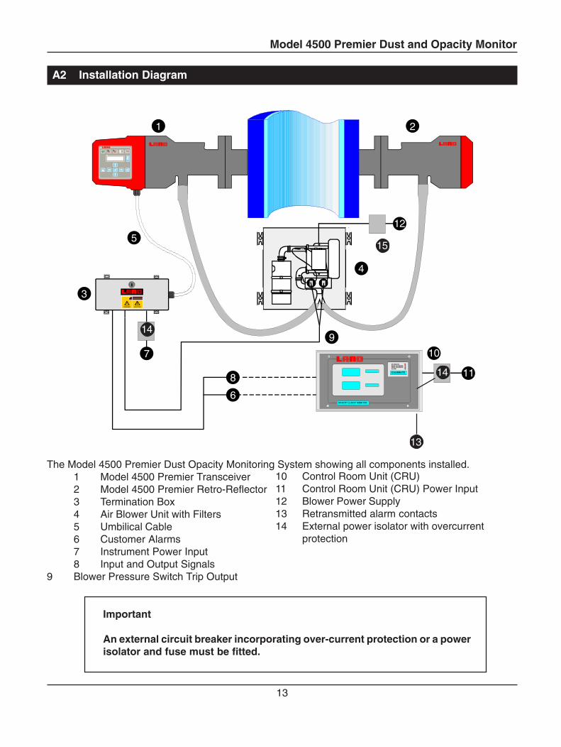
The Model 4500 Premier Dust Opacity Monitoring System showing all components installed.1 Model 4500 Premier Transceiver2 Model 4500 Premier Retro-Reflector3 Termination Box4 Air Blower Unit with Filters5 Umbilical Cable6 Customer Alarms7 Instrument Power Input8 Input and Output Signals
9 Blower Pressure Switch Trip Output
13
1 2
3
4
5
9
CAUTIONDANGER
7
8
10
OPACITY & DUST MONITOR
CALIBRATE
SYSTEM OKSPAN CALIBRATEZERO CALIBRATEALARM
11
6
12
14
14
15
10 Control Room Unit (CRU)11 Control Room Unit (CRU) Power Input12 Blower Power Supply13 Retransmitted alarm contacts14 External power isolator with overcurrent
protection
Important
An external circuit breaker incorporating over-current protection or a powerisolator and fuse must be fitted.
Model 4500 Premier Dust and Opacity Monitor
14
A3 Installation Instructions
A3-1 Installation Checklist
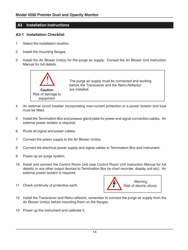
1 Select the installation location.
2 Install the mounting flanges.
3 Install the Air Blower Unit(s) for the purge air supply. Consult the Air Blower Unit InstructionManual for full details.
The purge air supply must be connected and workingbefore the Transceiver and the Retro-Reflectorare installed.
4 An external circuit breaker incorporating over-current protection or a power isolator and fusemust be fitted.
5 Install the Termination Box and prepare gland plate for power and signal connection cables. Anexternal power isolator is required.
6 Route all signal and power cables.
7 Connect the power supply to the Air Blower Unit(s).
8 Connect the electrical power supply and signal cables to Termination Box and instrument.
9 Power up air purge system.
10 Install and connect the Control Room Unit (see Control Room Unit Instruction Manual for fulldetails) or any other output devices to Termination Box (ie chart recorder, display unit etc). Anexternal power isolator is required.
11 Check continuity of protective earth.
12 Install the Transceiver and Retro-reflector, remember to connect the purge air supply from theAir Blower Unit(s) before mounting them on the flanges.
13 Power up the instrument and calibrate it.
CautionRisk of damage to
equipment
WarningRisk of electric shock.
Model 4500 Premier Dust and Opacity Monitor
15
A3-2 Selecting an Installation Location
The location of the mounting flanges may be affected by the type of Air Blower Unit(s) tobe used. Please refer to the Air Blower Unit manual.
1 For new plants, the location of the Transceiver should be planned during the design stages.For existing plants, it is critical that the best possible location be selected. The Transceivershould be mounted so that it can detect a representative concentration of dust across the stackor duct diameter.
2 If the monitor is to be used for US regulatory compliance the location should be determined bythe EPA installation specifications detailed in 40 CFR 60, Appendix B, Specification 1, or alocation approved by the appropriate agency.
3 At the installation location, there should be as much negative pressure as possible, for example,a stack updraft.
4 The mounting area must have a safe walkway: if necessary, a sufficiently large and accessibleplatform should be constructed.
5 Measurement errors may result if the Transceiver is subjected to strong vibrations or if thestack or duct changes shape as the gas temperature changes. If this cannot be avoided, avibration free mounting can be installed. Contact Land for information.
6 The ambient temperature at the mounting location must remain between -20°C and +55°C(-4°F and 131°F). If necessary, heating, ventilation, or isolation should be used to ensure thistemperature range is not exceeded.
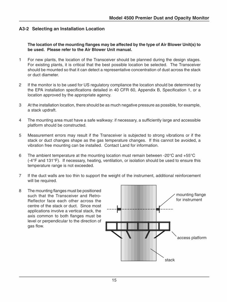
7 If the duct walls are too thin to support the weight of the instrument, additional reinforcementwill be required.
8 The mounting flanges must be positionedsuch that the Transceiver and Retro-Reflector face each other across thecentre of the stack or duct. Since mostapplications involve a vertical stack, theaxis common to both flanges must belevel or perpendicular to the direction ofgas flow.
mounting flangefor instrument
access platform
stack
Model 4500 Premier Dust and Opacity Monitor
16
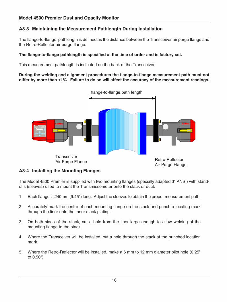
A3-3 Maintaining the Measurement Pathlength During Installation
The flange-to-flange pathlength is defined as the distance between the Transceiver air purge flange andthe Retro-Reflector air purge flange.
The flange-to-flange pathlength is specified at the time of order and is factory set.
This measurement pathlength is indicated on the back of the Transceiver.
During the welding and alignment procedures the flange-to-flange measurement path must notdiffer by more than ±1%. Failure to do so will affect the accuracy of the measurement readings.
A3-4 Installing the Mounting Flanges
The Model 4500 Premier is supplied with two mounting flanges (specially adapted 3" ANSI) with stand-offs (sleeves) used to mount the Transmissometer onto the stack or duct.
1 Each flange is 240mm (9.45") long. Adjust the sleeves to obtain the proper measurement path.
2 Accurately mark the centre of each mounting flange on the stack and punch a locating markthrough the liner onto the inner stack plating.
3 On both sides of the stack, cut a hole from the liner large enough to allow welding of themounting flange to the stack.
4 Where the Transceiver will be installed, cut a hole through the stack at the punched locationmark.
5 Where the Retro-Reflector will be installed, make a 6 mm to 12 mm diameter pilot hole (0.25"to 0.50")
TransceiverAir Purge Flange Retro-Reflector
Air Purge Flange
flange-to-flange path length
Model 4500 Premier Dust and Opacity Monitor
17
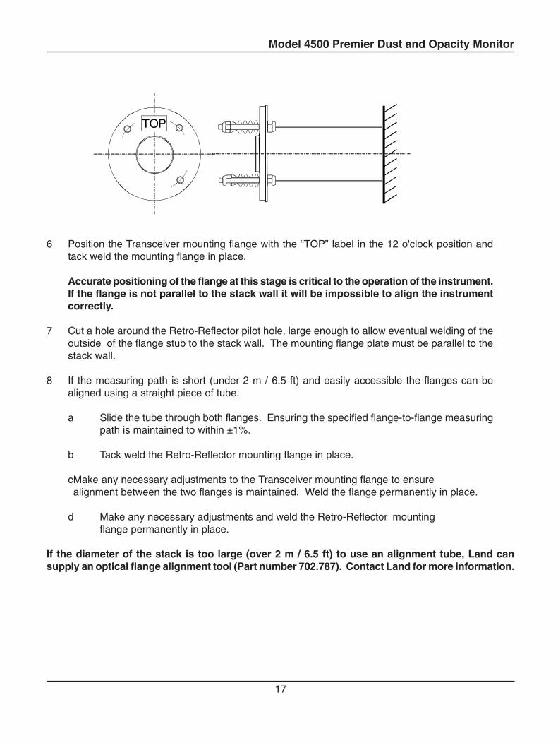
6 Position the Transceiver mounting flange with the “TOP” label in the 12 o'clock position andtack weld the mounting flange in place.
Accurate positioning of the flange at this stage is critical to the operation of the instrument.If the flange is not parallel to the stack wall it will be impossible to align the instrumentcorrectly.
7 Cut a hole around the Retro-Reflector pilot hole, large enough to allow eventual welding of theoutside of the flange stub to the stack wall. The mounting flange plate must be parallel to thestack wall.
8 If the measuring path is short (under 2 m / 6.5 ft) and easily accessible the flanges can bealigned using a straight piece of tube.
a Slide the tube through both flanges. Ensuring the specified flange-to-flange measuringpath is maintained to within ±1%.
b Tack weld the Retro-Reflector mounting flange in place.
cMake any necessary adjustments to the Transceiver mounting flange to ensurealignment between the two flanges is maintained. Weld the flange permanently in place.
d Make any necessary adjustments and weld the Retro-Reflector mountingflange permanently in place.
If the diameter of the stack is too large (over 2 m / 6.5 ft) to use an alignment tube, Land cansupply an optical flange alignment tool (Part number 702.787). Contact Land for more information.
TOP
Model 4500 Premier Dust and Opacity Monitor
18
A3-5 Mounting Details
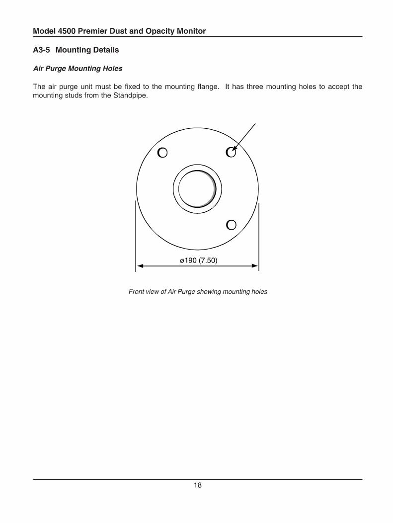
Air Purge Mounting Holes
The air purge unit must be fixed to the mounting flange. It has three mounting holes to accept themounting studs from the Standpipe.
ø190 (7.50)
Front view of Air Purge showing mounting holes
Model 4500 Premier Dust and Opacity Monitor
19
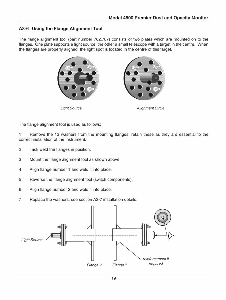
A3-6 Using the Flange Alignment Tool
The flange alignment tool (part number 702.787) consists of two plates which are mounted on to theflanges. One plate supports a light source, the other a small telescope with a target in the centre. Whenthe flanges are properly aligned, the light spot is located in the centre of this target.
The flange alignment tool is used as follows:
1 Remove the 12 washers from the mounting flanges, retain these as they are essential to thecorrect installation of the instrument.
2 Tack weld the flanges in position.
3 Mount the flange alignment tool as shown above.
4 Align flange number 1 and weld it into place.
5 Reverse the flange alignment tool (switch components).
6 Align flange number 2 and weld it into place.
7 Replace the washers, see section A3-7 installation details.
Flange 1Flange 2
Light Source
Light Source Alignment Circle
reinforcement ifrequired
Model 4500 Premier Dust and Opacity Monitor
20
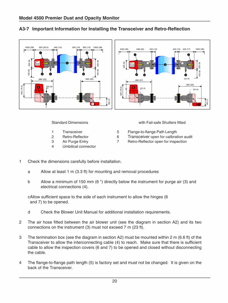
A3-7 Important Information for Installing the Transceiver and Retro-Reflection
Standard Dimensions with Fail-safe Shutters fitted
1 Transceiver 5 Flange-to-flange Path Length2 Retro-Reflector 6 Transceiver open for calibration audit3 Air Purge Entry 7 Retro-Reflector open for inspection4 Umbilical connector
1 Check the dimensions carefully before installation.
a Allow at least 1 m (3.3 ft) for mounting and removal procedures
b Allow a minimum of 150 mm (6 ") directly below the instrument for purge air (3) andelectrical connections (4).
cAllow sufficient space to the side of each instrument to allow the hinges (6and 7) to be opened.
d Check the Blower Unit Manual for additional installation requirements.
2 The air hose fitted between the air blower unit (see the diagram in section A2) and its twoconnections on the instrument (3) must not exceed 7 m (23 ft).
3 The termination box (see the diagram in section A2) must be mounted within 2 m (6.6 ft) of theTransceiver to allow the interconnecting cable (4) to reach. Make sure that there is sufficientcable to allow the inspection covers (6 and 7) to be opened and closed without disconnectingthe cable.
4 The flange-to-flange path length (5) is factory set and must not be changed. It is given on theback of the Transceiver.
638 (25) 240 (10) 440 (17)
220
(9)
150
(6)
220
(9)
240 (10) 1000 (39)1000 (39)
690 (27)
500 (20)
4
6
7
5
1 2
3 3
420
(16
.5)
160
(7)
220 (9)
220 (9)
W 220 (9)
3
520 (20.5) 240 (10) 320 (13)
220
(9)
150
(6)
220
(9)
240 (10) 1000 (39)
34
1000 (39)
580 (23)
420
(16.
5) 6
500 (20)
160
(7)
150
(6)
5
1 2
7
220 (9)
Model 4500 Premier Dust and Opacity Monitor
21
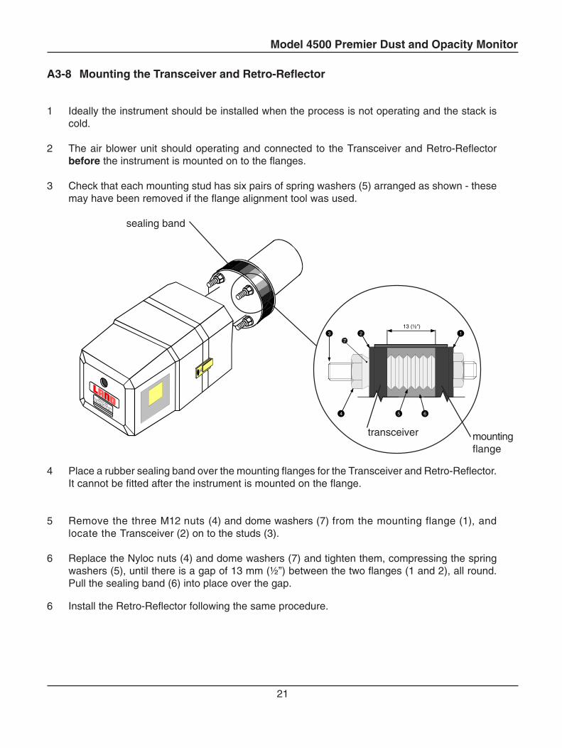
A3-8 Mounting the Transceiver and Retro-Reflector
1 Ideally the instrument should be installed when the process is not operating and the stack iscold.
2 The air blower unit should operating and connected to the Transceiver and Retro-Reflectorbefore the instrument is mounted on to the flanges.
3 Check that each mounting stud has six pairs of spring washers (5) arranged as shown - thesemay have been removed if the flange alignment tool was used.
4 Place a rubber sealing band over the mounting flanges for the Transceiver and Retro-Reflector.It cannot be fitted after the instrument is mounted on the flange.
5 Remove the three M12 nuts (4) and dome washers (7) from the mounting flange (1), andlocate the Transceiver (2) on to the studs (3).
6 Replace the Nyloc nuts (4) and dome washers (7) and tighten them, compressing the springwashers (5), until there is a gap of 13 mm (½”) between the two flanges (1 and 2), all round.Pull the sealing band (6) into place over the gap.
6 Install the Retro-Reflector following the same procedure.
sealing band
123
4 5 6
13 (½")
7
mountingflange
transceiver
Model 4500 Premier Dust and Opacity Monitor
22
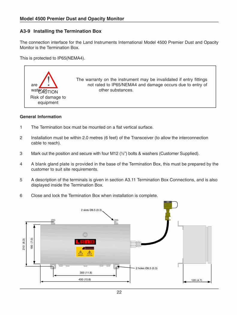
A3-9 Installing the Termination Box
The connection interface for the Land Instruments International Model 4500 Premier Dust and OpacityMonitor is the Termination Box.
This is protected to IP65(NEMA4).
The warranty on the instrument may be invalidated if entry fittingsare not rated to IP65/NEMA4 and damage occurs due to entry ofwater or other substances.
General Information
1 The Termination box must be mounted on a flat vertical surface.
2 Installation must be within 2.0 metres (6 feet) of the Transceiver (to allow the interconnectioncable to reach).
3 Mark out the position and secure with four M12 (½”) bolts & washers (Customer Supplied).
4 A blank gland plate is provided in the base of the Termination Box, this must be prepared by thecustomer to suit site requirements.
5 A description of the terminals is given in section A3.11 Termination Box Connections, and is alsodisplayed inside the Termination Box.
6 Close and lock the Termination Box when installation is complete.
CAUTIONRisk of damage to
equipment
300 (11.8)
400 (15.8)
210
(8.
3)
120 (4.7)
2 slots Ø8.5 (0.3)
CAUTIONDANGER
180
(7.
0)
2 holes Ø8.5 (0.3)
Model 4500 Premier Dust and Opacity Monitor
23
A3-10 Electrical Connections
All switch cabinets, distribution boxes, fuses and other components for electrical installation must be providedby the customer, as must the mains power supply connections. Installation should be carried out by acompetent person and cables should satisfy current carrying capacity and voltage rating.
Mains SupplyThe following mains power supply connections must be made for:
Termination BoxAir Blower Unit(s)Control Room Unit (see CRU Instruction Manual 770.043)Additional equipment (i.e. chart recorder etc.)
Signal ConnectionsThe following signal cables must be connected via the Termination Box:
Umbilical cable to transceiverAir Blower pressure switch interconnectionsControl Room UnitCustomer AlarmsCurrent Loop Maintenance Switch
Optional ConnectionsThe following cable connections must be made where required by the application
Status relay connectionsSerial data communications
Air Blower Unit Motor ConnectionsRefer to the Instruction Manual supplied with the Air Blower Unit.
Model 4500 Premier Dust and Opacity Monitor
24
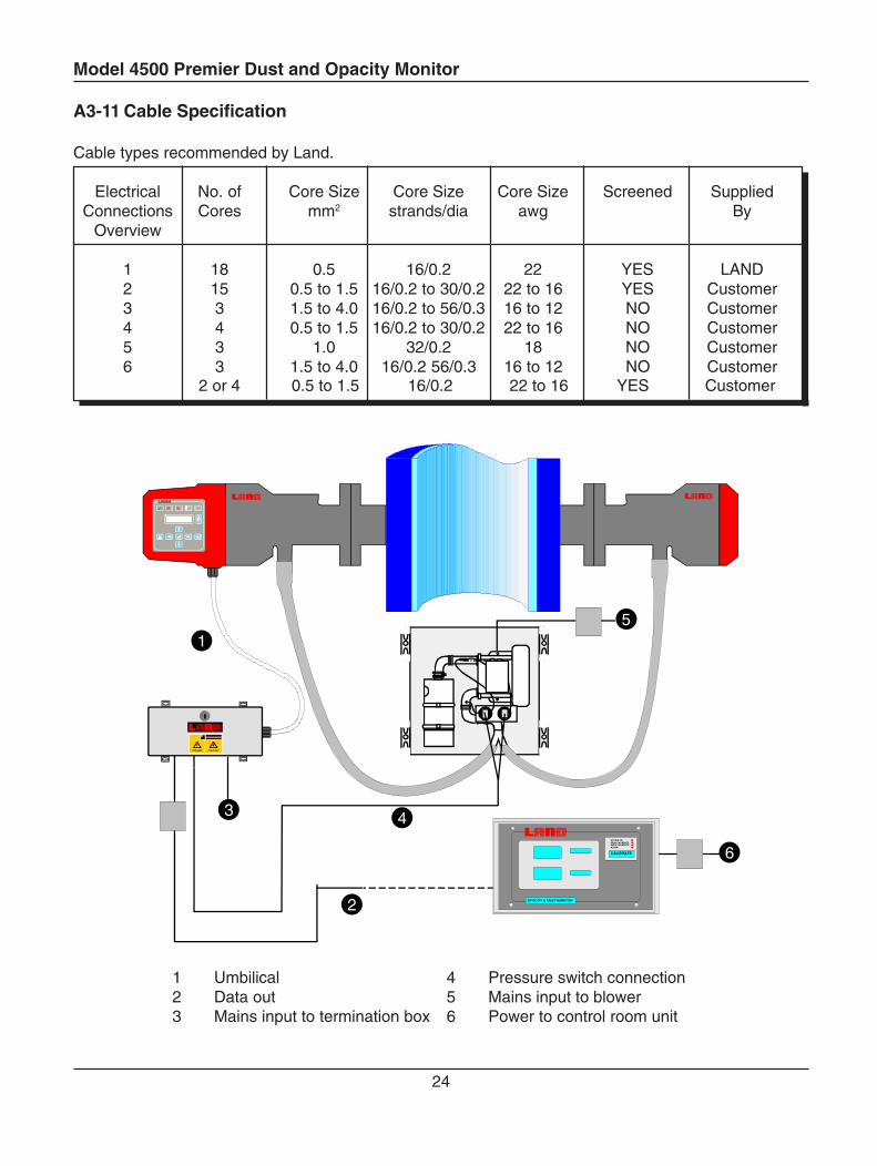
A3-11 Cable Specification
Cable types recommended by Land.
Electrical No. of Core Size Core Size Core Size Screened SuppliedConnections Cores mm2 strands/dia awg By
Overview
1 18 0.5 16/0.2 22 YES LAND2 15 0.5 to 1.5 16/0.2 to 30/0.2 22 to 16 YES Customer3 3 1.5 to 4.0 16/0.2 to 56/0.3 16 to 12 NO Customer4 4 0.5 to 1.5 16/0.2 to 30/0.2 22 to 16 NO Customer5 3 1.0 32/0.2 18 NO Customer6 3 1.5 to 4.0 16/0.2 56/0.3 16 to 12 NO Customer
1
2
3 4
5
CAUTIONDANGER
OPACITY & DUST MONITOR
CALIBRATE
SYSTEM OKSPAN CALIBRATEZERO CALIBRATEALARM
6
2 or 4 0.5 to 1.5 16/0.2 22 to 16 YES Customer
1 Umbilical2 Data out3 Mains input to termination box
4 Pressure switch connection5 Mains input to blower6 Power to control room unit
Model 4500 Premier Dust and Opacity Monitor
25
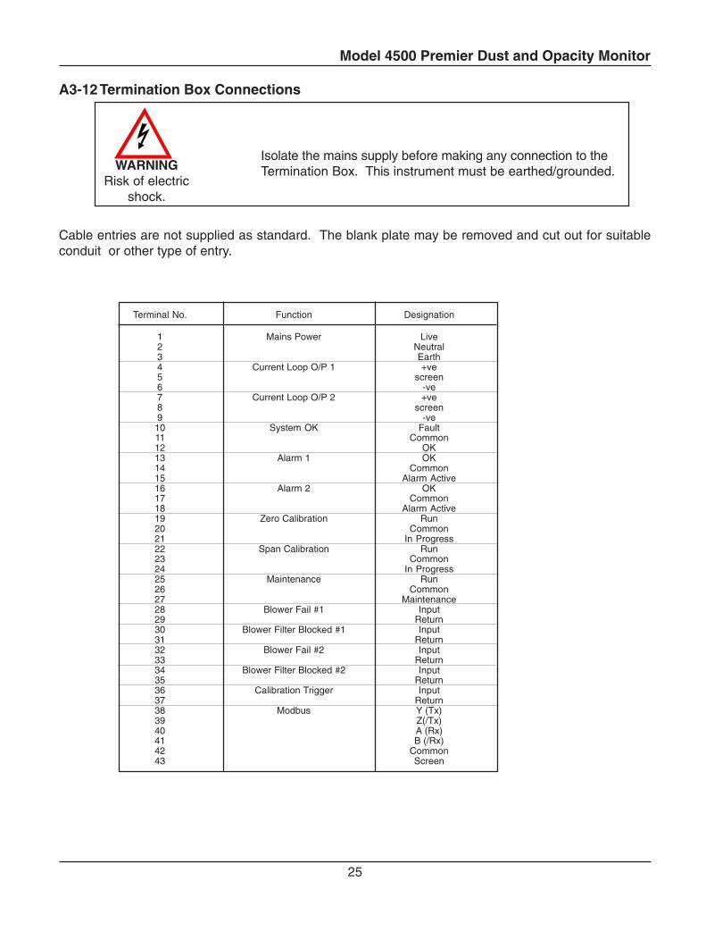
A3-12 Termination Box Connections
Isolate the mains supply before making any connection to theTermination Box. This instrument must be earthed/grounded.
Cable entries are not supplied as standard. The blank plate may be removed and cut out for suitableconduit or other type of entry.
Terminal No. Function Designation
1 Mains Power Live2 Neutral3 Earth4 Current Loop O/P 1 +ve5 screen6 -ve7 Current Loop O/P 2 +ve8 screen9 -ve10 System OK Fault11 Common12 OK13 Alarm 1 OK14 Common15 Alarm Active16 Alarm 2 OK17 Common18 Alarm Active19 Zero Calibration Run20 Common21 In Progress22 Span Calibration Run23 Common24 In Progress25 Maintenance Run26 Common27 Maintenance28 Blower Fail #1 Input29 Return30 Blower Filter Blocked #1 Input31 Return32 Blower Fail #2 Input33 Return34 Blower Filter Blocked #2 Input35 Return36 Calibration Trigger Input37 Return38 Modbus Y (Tx)39 Z(/Tx)40 A (Rx)41 B (/Rx)42 Common43 Screen
WARNINGRisk of electric
shock.
Model 4500 Premier Dust and Opacity Monitor
26
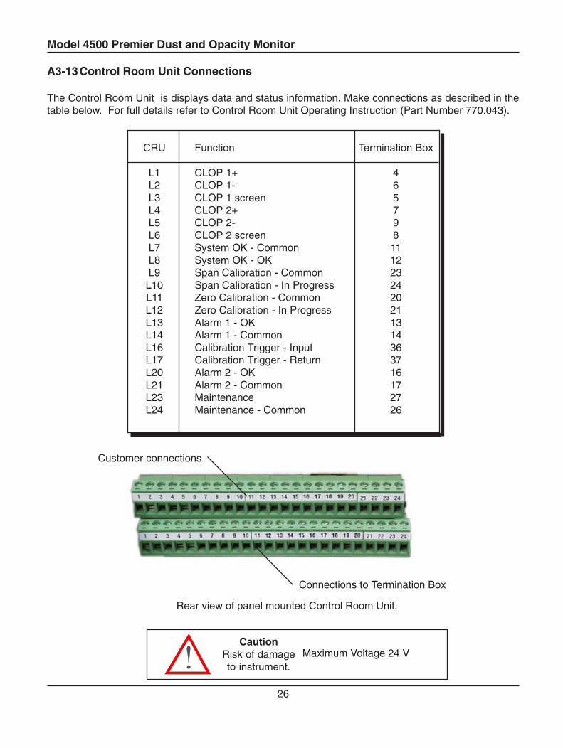
A3-13Control Room Unit Connections
The Control Room Unit is displays data and status information. Make connections as described in thetable below. For full details refer to Control Room Unit Operating Instruction (Part Number 770.043).
CRU Function Termination Box
L1 CLOP 1+ 4L2 CLOP 1- 6L3 CLOP 1 screen 5L4 CLOP 2+ 7L5 CLOP 2- 9L6 CLOP 2 screen 8L7 System OK - Common 11L8 System OK - OK 12L9 Span Calibration - Common 23
L10 Span Calibration - In Progress 24L11 Zero Calibration - Common 20L12 Zero Calibration - In Progress 21L13 Alarm 1 - OK 13L14 Alarm 1 - Common 14L16 Calibration Trigger - Input 36L17 Calibration Trigger - Return 37L20 Alarm 2 - OK 16L21 Alarm 2 - Common 17L23 Maintenance 27L24 Maintenance - Common 26
Customer connections
Connections to Termination Box
Maximum Voltage 24 VCaution
Risk of damageto instrument.
Rear view of panel mounted Control Room Unit.
Model 4500 Premier Dust and Opacity Monitor
27
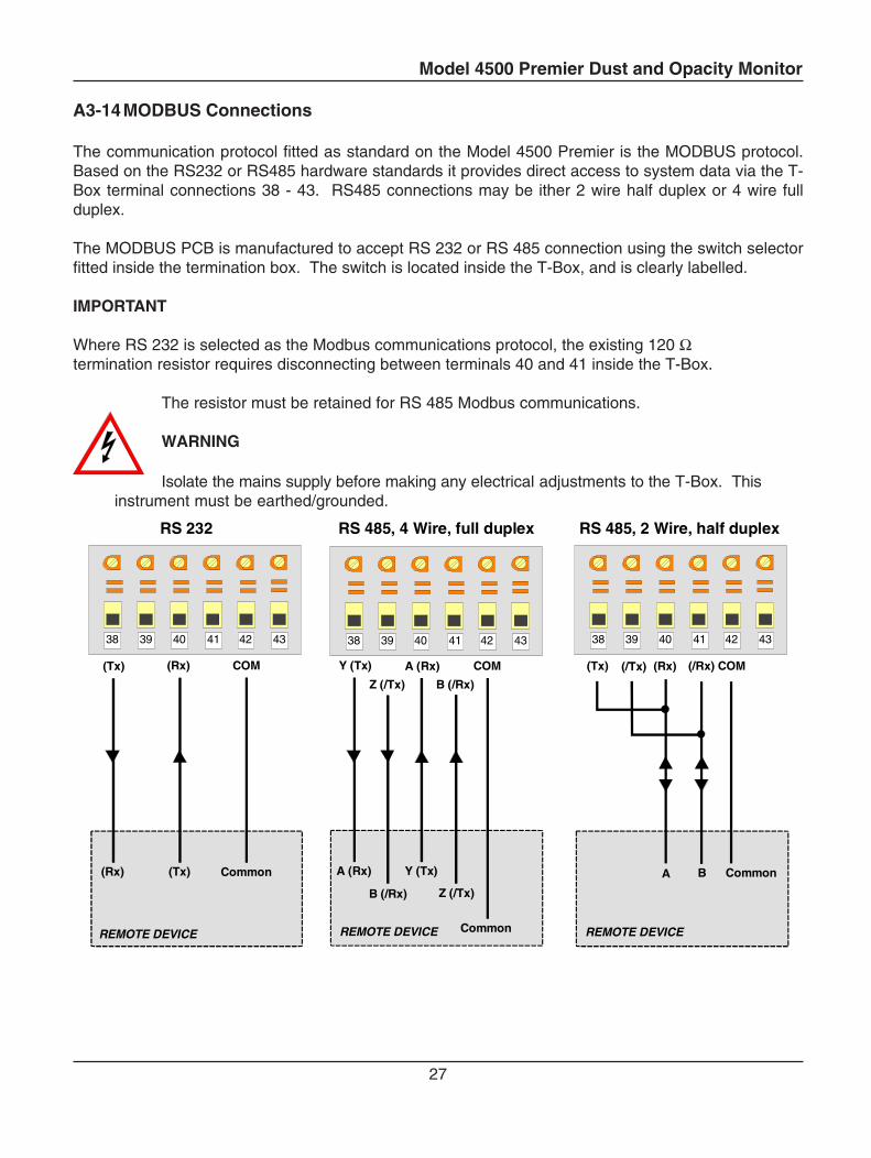
A3-14MODBUS Connections
The communication protocol fitted as standard on the Model 4500 Premier is the MODBUS protocol.Based on the RS232 or RS485 hardware standards it provides direct access to system data via the T-Box terminal connections 38 - 43. RS485 connections may be ither 2 wire half duplex or 4 wire fullduplex.
The MODBUS PCB is manufactured to accept RS 232 or RS 485 connection using the switch selectorfitted inside the termination box. The switch is located inside the T-Box, and is clearly labelled.
IMPORTANT
Where RS 232 is selected as the Modbus communications protocol, the existing 120 Ωtermination resistor requires disconnecting between terminals 40 and 41 inside the T-Box.
The resistor must be retained for RS 485 Modbus communications.
WARNING
Isolate the mains supply before making any electrical adjustments to the T-Box. Thisinstrument must be earthed/grounded.
38 39 40 41 42 43
(Tx)(Rx) Common
RS 232
38 39 40 41 42 43
A (Rx)
B (/Rx)
Y (Tx)
Z (/Tx)
Common
RS 485, 4 Wire, full duplex
38 39 40 41 42 43
A B Common
RS 485, 2 Wire, half duplex
(Tx) (Rx) COM Y (Tx)
Z (/Tx)
A (Rx)
B (/Rx)
COM
REMOTE DEVICE
(Tx) (/Tx) (Rx) (/Rx) COM
REMOTE DEVICE REMOTE DEVICE

Model 4500 Premier Dust and Opacity Monitor
28
Model 4500 Premier Dust and Opacity Monitor
29
B1 Getting Started
B1-1 The User Interface
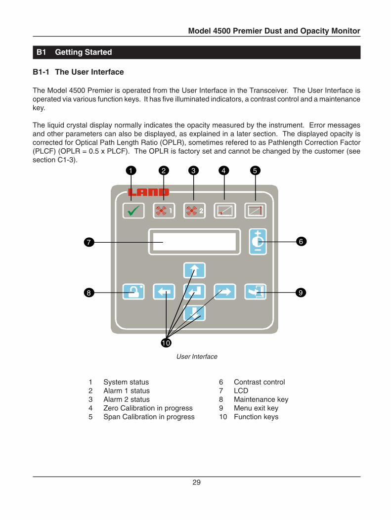
The Model 4500 Premier is operated from the User Interface in the Transceiver. The User Interface isoperated via various function keys. It has five illuminated indicators, a contrast control and a maintenancekey.
The liquid crystal display normally indicates the opacity measured by the instrument. Error messagesand other parameters can also be displayed, as explained in a later section. The displayed opacity iscorrected for Optical Path Length Ratio (OPLR), sometimes refered to as Pathlength Correction Factor(PLCF) (OPLR = 0.5 x PLCF). The OPLR is factory set and cannot be changed by the customer (seesection C1-3).
7
8
10
1 2 3 4 5
6
9
User Interface
1 System status 6 Contrast control2 Alarm 1 status 7 LCD3 Alarm 2 status 8 Maintenance key4 Zero Calibration in progress 9 Menu exit key5 Span Calibration in progress 10 Function keys
Model 4500 Premier Dust and Opacity Monitor
30
B1-2 Function Keys
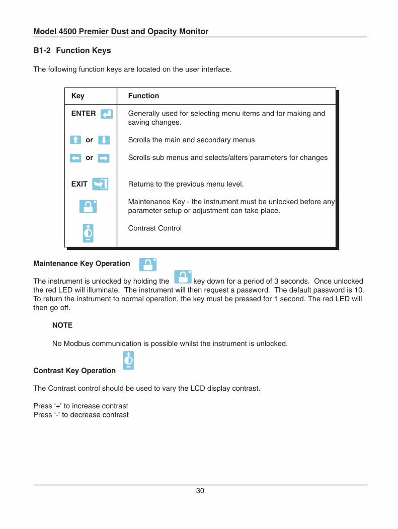
The following function keys are located on the user interface.
Key Function
ENTER Generally used for selecting menu items and for making andsaving changes.
or Scrolls the main and secondary menus
or Scrolls sub menus and selects/alters parameters for changes
EXIT Returns to the previous menu level.
Maintenance Key - the instrument must be unlocked before anyparameter setup or adjustment can take place.
Contrast Control
Maintenance Key Operation
The instrument is unlocked by holding the key down for a period of 3 seconds. Once unlockedthe red LED will illuminate. The instrument will then request a password. The default password is 10.To return the instrument to normal operation, the key must be pressed for 1 second. The red LED willthen go off.
NOTE
No Modbus communication is possible whilst the instrument is unlocked.
Contrast Key Operation
The Contrast control should be used to vary the LCD display contrast.
Press ‘+’ to increase contrastPress ‘-’ to decrease contrast
Model 4500 Premier Dust and Opacity Monitor
31
B1-3 Glossary of Terms
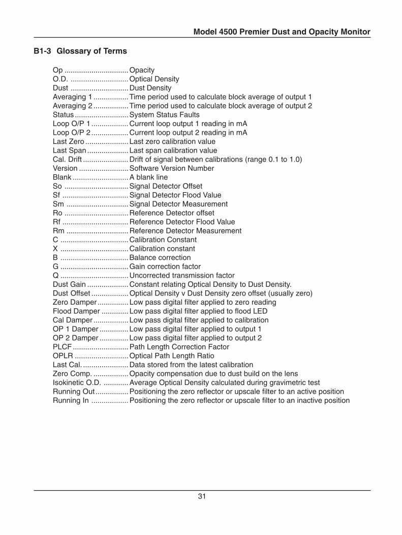
Op ...............................OpacityO.D. ............................Optical DensityDust ............................Dust DensityAveraging 1 .................Time period used to calculate block average of output 1Averaging 2 .................Time period used to calculate block average of output 2Status ..........................System Status FaultsLoop O/P 1.................. Current loop output 1 reading in mALoop O/P 2.................. Current loop output 2 reading in mALast Zero ..................... Last zero calibration valueLast Span .................... Last span calibration valueCal. Drift ...................... Drift of signal between calibrations (range 0.1 to 1.0)Version ........................Software Version NumberBlank ........................... A blank lineSo ...............................Signal Detector OffsetSf ................................ Signal Detector Flood ValueSm .............................. Signal Detector MeasurementRo ...............................Reference Detector offsetRf ................................ Reference Detector Flood ValueRm .............................. Reference Detector MeasurementC .................................Calibration ConstantX .................................Calibration constantB .................................Balance correctionG .................................Gain correction factorQ .................................Uncorrected transmission factorDust Gain .................... Constant relating Optical Density to Dust Density.Dust Offset .................. Optical Density v Dust Density zero offset (usually zero)Zero Damper ............... Low pass digital filter applied to zero readingFlood Damper ............. Low pass digital filter applied to flood LEDCal Damper ................. Low pass digital filter applied to calibrationOP 1 Damper .............. Low pass digital filter applied to output 1OP 2 Damper .............. Low pass digital filter applied to output 2PLCF ........................... Path Length Correction FactorOPLR ..........................Optical Path Length RatioLast Cal. ...................... Data stored from the latest calibrationZero Comp. .................Opacity compensation due to dust build on the lensIsokinetic O.D. ............Average Optical Density calculated during gravimetric testRunning Out ................Positioning the zero reflector or upscale filter to an active positionRunning In .................. Positioning the zero reflector or upscale filter to an inactive position
Model 4500 Premier Dust and Opacity Monitor
32
B1-4 Using the Instrument for the First Time
Tools required: a 19 mm spanner and a 5 mm hexagonal (Allen) key (supplied).The following instructions must be adhered to for the correct running of the instrument.
1. Complete Installation
Ensure installation has been completed, including any optional equipment e.g. Control Room Unit (CRU).
2. Check Display is Legible
Once the instrument is powered up, check that the LCD display has acceptable visibility. Adjust thedisplay contrast using the key as appropriate.
3. Check the Optical Path Length Ratio (OPLR). See section C1-3.
↑↓
↵↵↵↵↵
↑↓
EXIT
Opacity: 0.0%Parameters: ↔↵↵↵↵↵
OPLR: 0.5↑↓
So: 0↑↓
Opacity: 0.0%Parameters: ↔↵↵↵↵↵
Opacity: 0.0%Faults: ↑↓↵↵↵↵↵
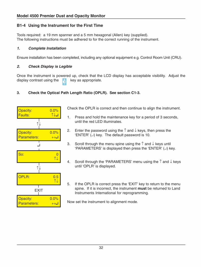
Check the OPLR is correct and then continue to align the instrument.
1. Press and hold the maintenance key for a period of 3 seconds,until the red LED illuminates.
2. Enter the password using the ↑ and ↓ keys, then press the‘ENTER’ (↵) key. The default password is 10.
3. Scroll through the menu spine using the ↑ and ↓ keys until‘PARAMETERS’ is displayed then press the ‘ENTER’ (↵) key.
4. Scroll through the ‘PARAMETERS’ menu using the ↑ and ↓ keysuntil ‘OPLR’ is displayed.
5. If the OPLR is correct press the ‘EXIT’ key to return to the menuspine. If it is incorrect, the instrument must be returned to LandInstruments International for reprogramming.
Now set the instrument to alignment mode.
Model 4500 Premier Dust and Opacity Monitor
33
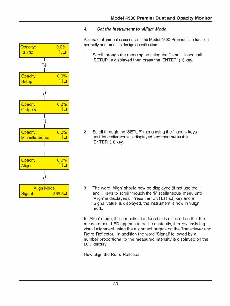
4. Set the Instrument to ‘Align’ Mode
Accurate alignment is essential if the Model 4500 Premier is to functioncorrectly and meet its design specification.
1. Scroll through the menu spine using the ↑ and ↓ keys until‘SETUP’ is displayed then press the ‘ENTER’ (↵↵↵↵↵) key.
2. Scroll through the ‘SETUP’ menu using the ↑ and ↓ keysuntil ‘Miscellaneous’ is displayed and then press the‘ENTER’ (↵↵↵↵↵) key.
3. The word ‘Align’ should now be displayed (if not use the ↑and ↓ keys to scroll through the ‘Miscellaneous’ menu until‘Align’ is displayed). Press the ‘ENTER’ (↵↵↵↵↵) key and a‘Signal value’ is displayed, the instrument is now in ‘Align’mode.
In ‘Align’ mode, the normalisation function is disabled so that themeasurement LED appears to be lit constantly, thereby assistingvisual alignment using the alignment targets on the Transciever andRetro-Reflector. In addition the word 'Signal' followed by anumber proportional to the measured intensity is displayed on theLCD display.
Now align the Retro-Reflector.
↑↓
↵↵↵↵↵
↑↓
↵↵↵↵↵
↵↵↵↵↵
Opacity: 0.0%Setup: ↑↓↵↵↵↵↵
Align ModeSignal: 235.3↵↵↵↵↵
Opacity: 0.0%Align: ↑↓↵↵↵↵↵
Opacity: 0.0%Miscellaneous: ↑↓↵↵↵↵↵
Opacity: 0.0%Outputs: ↑↓↵↵↵↵↵
Opacity: 0.0%Faults: ↑↓↵↵↵↵↵
Model 4500 Premier Dust and Opacity Monitor
34
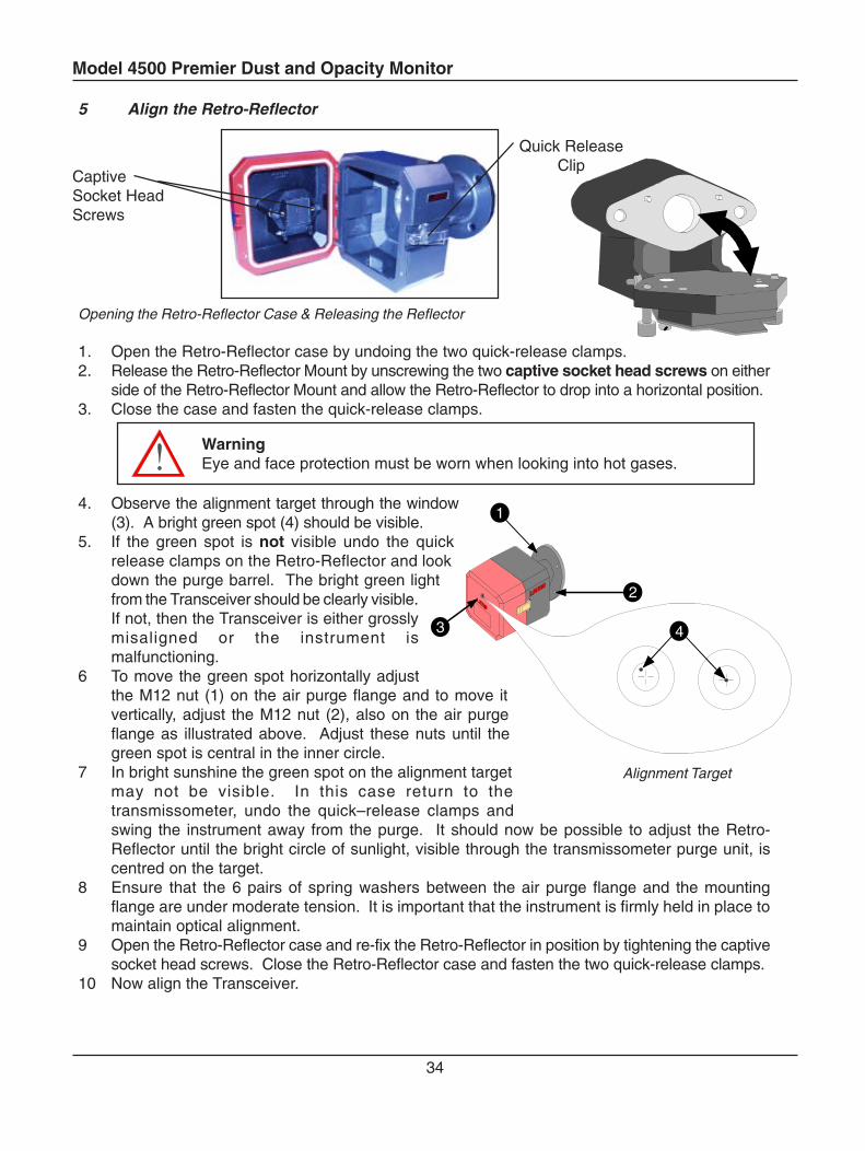
5 Align the Retro-Reflector
Opening the Retro-Reflector Case & Releasing the Reflector
1. Open the Retro-Reflector case by undoing the two quick-release clamps.2. Release the Retro-Reflector Mount by unscrewing the two captive socket head screws on either
side of the Retro-Reflector Mount and allow the Retro-Reflector to drop into a horizontal position.3. Close the case and fasten the quick-release clamps.
WarningEye and face protection must be worn when looking into hot gases.
4. Observe the alignment target through the window(3). A bright green spot (4) should be visible.
5. If the green spot is not visible undo the quickrelease clamps on the Retro-Reflector and lookdown the purge barrel. The bright green lightfrom the Transceiver should be clearly visible.If not, then the Transceiver is either grosslymisaligned or the instrument ismalfunctioning.
6 To move the green spot horizontally adjustthe M12 nut (1) on the air purge flange and to move itvertically, adjust the M12 nut (2), also on the air purgeflange as illustrated above. Adjust these nuts until thegreen spot is central in the inner circle.
7 In bright sunshine the green spot on the alignment targetmay not be visible. In this case return to thetransmissometer, undo the quick–release clamps andswing the instrument away from the purge. It should now be possible to adjust the Retro-Reflector until the bright circle of sunlight, visible through the transmissometer purge unit, iscentred on the target.
8 Ensure that the 6 pairs of spring washers between the air purge flange and the mountingflange are under moderate tension. It is important that the instrument is firmly held in place tomaintain optical alignment.
9 Open the Retro-Reflector case and re-fix the Retro-Reflector in position by tightening the captivesocket head screws. Close the Retro-Reflector case and fasten the two quick-release clamps.
10 Now align the Transceiver.
CaptiveSocket HeadScrews
Quick ReleaseClip
Alignment Target
1
3
2
4
Model 4500 Premier Dust and Opacity Monitor
35
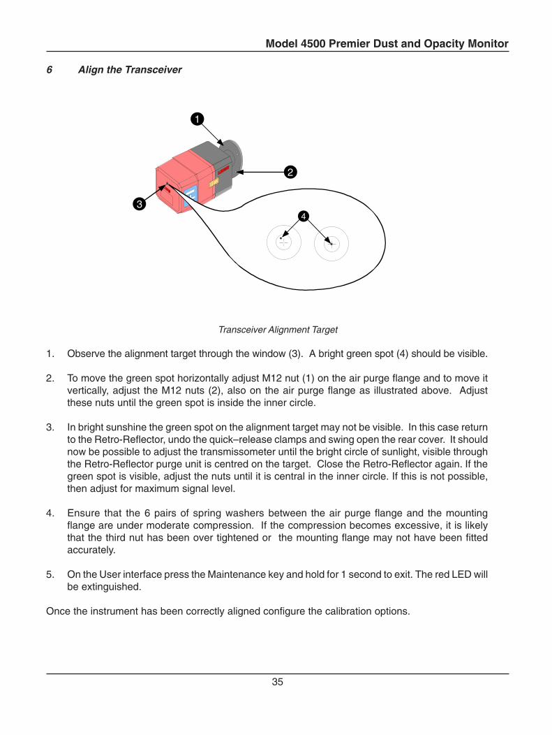
6 Align the Transceiver
Transceiver Alignment Target
1. Observe the alignment target through the window (3). A bright green spot (4) should be visible.
2. To move the green spot horizontally adjust M12 nut (1) on the air purge flange and to move itvertically, adjust the M12 nuts (2), also on the air purge flange as illustrated above. Adjustthese nuts until the green spot is inside the inner circle.
3. In bright sunshine the green spot on the alignment target may not be visible. In this case returnto the Retro-Reflector, undo the quick–release clamps and swing open the rear cover. It shouldnow be possible to adjust the transmissometer until the bright circle of sunlight, visible throughthe Retro-Reflector purge unit is centred on the target. Close the Retro-Reflector again. If thegreen spot is visible, adjust the nuts until it is central in the inner circle. If this is not possible,then adjust for maximum signal level.
4. Ensure that the 6 pairs of spring washers between the air purge flange and the mountingflange are under moderate compression. If the compression becomes excessive, it is likelythat the third nut has been over tightened or the mounting flange may not have been fittedaccurately.
5. On the User interface press the Maintenance key and hold for 1 second to exit. The red LED willbe extinguished.
Once the instrument has been correctly aligned configure the calibration options.
3
2
1
4
Model 4500 Premier Dust and Opacity Monitor
36
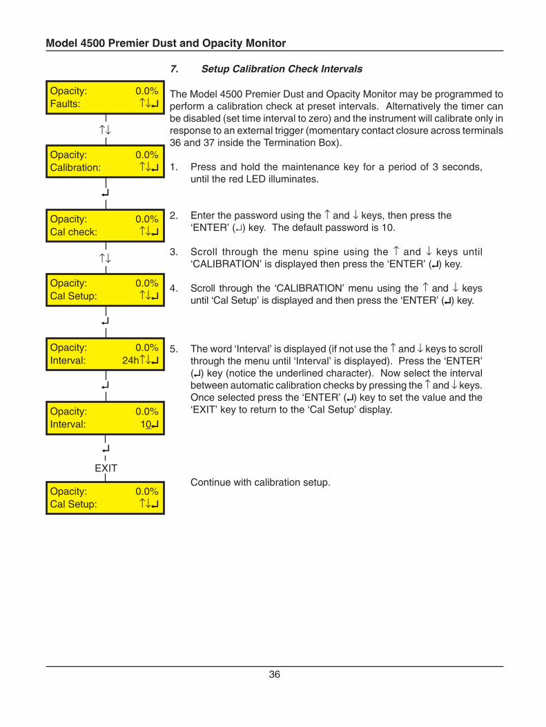
7. Setup Calibration Check Intervals
The Model 4500 Premier Dust and Opacity Monitor may be programmed toperform a calibration check at preset intervals. Alternatively the timer canbe disabled (set time interval to zero) and the instrument will calibrate only inresponse to an external trigger (momentary contact closure across terminals36 and 37 inside the Termination Box).
1. Press and hold the maintenance key for a period of 3 seconds,until the red LED illuminates.
2. Enter the password using the ↑ and ↓ keys, then press the‘ENTER’ (↵) key. The default password is 10.
3. Scroll through the menu spine using the ↑ and ↓ keys until‘CALIBRATION’ is displayed then press the ‘ENTER’ (↵↵↵↵↵) key.
4. Scroll through the ‘CALIBRATION’ menu using the ↑ and ↓ keysuntil ‘Cal Setup’ is displayed and then press the ‘ENTER’ (↵↵↵↵↵) key.
5. The word ‘Interval’ is displayed (if not use the ↑ and ↓ keys to scrollthrough the menu until ‘Interval’ is displayed). Press the ‘ENTER’(↵↵↵↵↵) key (notice the underlined character). Now select the intervalbetween automatic calibration checks by pressing the ↑ and ↓ keys.Once selected press the ‘ENTER’ (↵↵↵↵↵) key to set the value and the‘EXIT’ key to return to the ‘Cal Setup’ display.
Continue with calibration setup.
↵↵↵↵↵
EXIT
↵↵↵↵↵
↵↵↵↵↵
↑↓
↑↓
↵↵↵↵↵
Opacity: 0.0%Faults: ↑↓↵↵↵↵↵
Opacity: 0.0%Calibration: ↑↓↵↵↵↵↵
Opacity: 0.0%Cal check: ↑↓↵↵↵↵↵
Opacity: 0.0%Cal Setup: ↑↓↵↵↵↵↵
Opacity: 0.0%Interval: 24h↑↓↵↵↵↵↵
Opacity: 0.0%Interval: 10↵↵↵↵↵
Opacity: 0.0%Cal Setup: ↑↓↵↵↵↵↵
Model 4500 Premier Dust and Opacity Monitor
37
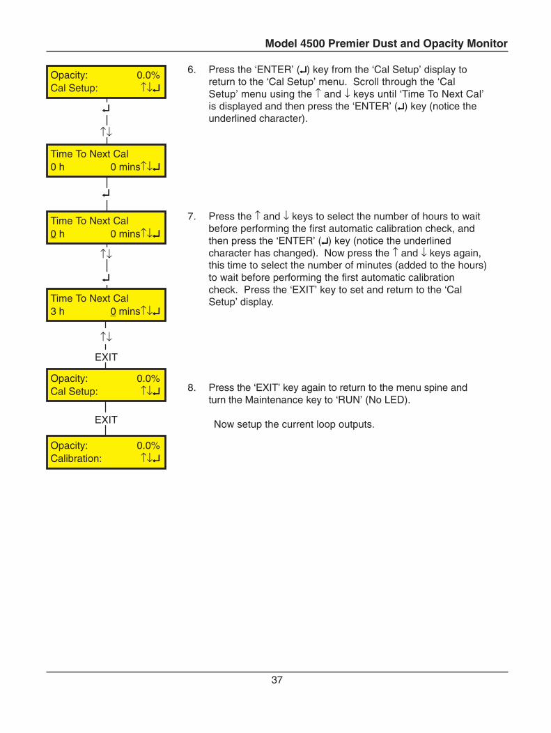
6. Press the ‘ENTER’ (↵↵↵↵↵) key from the ‘Cal Setup’ display toreturn to the ‘Cal Setup’ menu. Scroll through the ‘CalSetup’ menu using the ↑ and ↓ keys until ‘Time To Next Cal’is displayed and then press the ‘ENTER’ (↵↵↵↵↵) key (notice theunderlined character).
7. Press the ↑ and ↓ keys to select the number of hours to waitbefore performing the first automatic calibration check, andthen press the ‘ENTER’ (↵↵↵↵↵) key (notice the underlinedcharacter has changed). Now press the ↑ and ↓ keys again,this time to select the number of minutes (added to the hours)to wait before performing the first automatic calibrationcheck. Press the ‘EXIT’ key to set and return to the ‘CalSetup’ display.
8. Press the ‘EXIT’ key again to return to the menu spine andturn the Maintenance key to ‘RUN’ (No LED).
Now setup the current loop outputs.
↑↓
EXIT
↵↵↵↵↵
↑↓
↵↵↵↵↵
↵↵↵↵↵
↑↓
Opacity: 0.0%Cal Setup: ↑↓↵↵↵↵↵
Time To Next Cal0 h 0 mins↑↓↵↵↵↵↵
Time To Next Cal0 h 0 mins↑↓↵↵↵↵↵
Time To Next Cal3 h 0 mins↑↓↵↵↵↵↵
EXIT
Opacity: 0.0%Cal Setup: ↑↓↵↵↵↵↵
Opacity: 0.0%Calibration: ↑↓↵↵↵↵↵
Model 4500 Premier Dust and Opacity Monitor
38
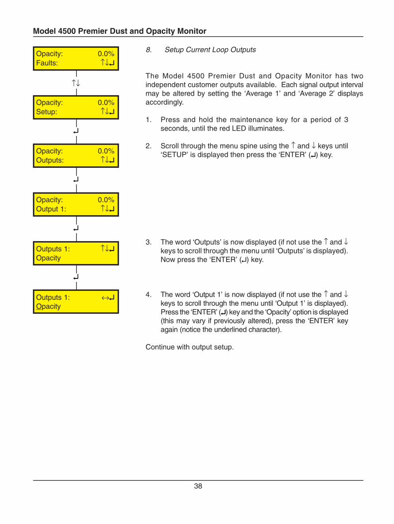
8. Setup Current Loop Outputs
The Model 4500 Premier Dust and Opacity Monitor has twoindependent customer outputs available. Each signal output intervalmay be altered by setting the ‘Average 1’ and ‘Average 2’ displaysaccordingly.
1. Press and hold the maintenance key for a period of 3seconds, until the red LED illuminates.
2. Scroll through the menu spine using the ↑ and ↓ keys until‘SETUP’ is displayed then press the ‘ENTER’ (↵↵↵↵↵) key.
3. The word ‘Outputs’ is now displayed (if not use the ↑ and ↓keys to scroll through the menu until ‘Outputs’ is displayed).Now press the ‘ENTER’ (↵↵↵↵↵) key.
4. The word ‘Output 1’ is now displayed (if not use the ↑ and ↓keys to scroll through the menu until ‘Output 1’ is displayed).Press the ‘ENTER’ (↵↵↵↵↵) key and the ‘Opacity’ option is displayed(this may vary if previously altered), press the ‘ENTER’ keyagain (notice the underlined character).
Continue with output setup.
↑↓
↵↵↵↵↵
↵↵↵↵↵
↵↵↵↵↵
↵↵↵↵↵
Opacity: 0.0%Faults: ↑↓↵↵↵↵↵
Opacity: 0.0%Setup: ↑↓↵↵↵↵↵
Opacity: 0.0%Outputs: ↑↓↵↵↵↵↵
Opacity: 0.0%Output 1: ↑↓↵↵↵↵↵
Outputs 1: ↑↓↵↵↵↵↵Opacity
Outputs 1: ↔↵↵↵↵↵Opacity
Model 4500 Premier Dust and Opacity Monitor
39
↵↵↵↵↵
→←
↵↵↵↵↵
↑↓
↵↵↵↵↵
↑↓
↵↵↵↵↵
↑↓
↵↵↵↵↵
→←
EXIT
Outputs 1: ↔↵↵↵↵↵Opacity
Outputs 1: ↑↓↵↵↵↵↵OD
Outputs 1: ↑↓↵↵↵↵↵Range: 1.6
Outputs 1: ↑↓↵↵↵↵↵Range: 3.0
Outputs 1: ↑↓↵↵↵↵↵During Cal: TRACK
Outputs 1: ↑↓↵↵↵↵↵During Cal: HOLD
Opacity: 0.0%Output 1: ↑↓↵↵↵↵↵
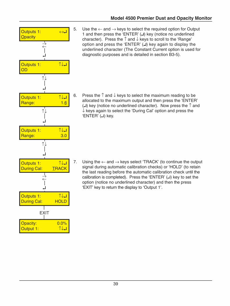
5. Use the ← and → keys to select the required option for Output1 and then press the ‘ENTER’ (↵↵↵↵↵) key (notice no underlinedcharacter). Press the ↑ and ↓ keys to scroll to the ‘Range’option and press the ‘ENTER’ (↵↵↵↵↵) key again to display theunderlined character (The Constant Current option is used fordiagnostic purposes and is detailed in section B3-5).
6. Press the ↑ and ↓ keys to select the maximum reading to beallocated to the maximum output and then press the ‘ENTER’(↵↵↵↵↵) key (notice no underlined character). Now press the ↑ and↓ keys again to select the ‘During Cal’ option and press the‘ENTER’ (↵↵↵↵↵) key.
7. Using the ← and → keys select ‘TRACK’ (to continue the outputsignal during automatic calibration checks) or ‘HOLD’ (to retainthe last reading before the automatic calibration check until thecalibration is completed). Press the ‘ENTER’ (↵↵↵↵↵) key to set theoption (notice no underlined character) and then the press‘EXIT’ key to return the display to ‘Output 1’.
Model 4500 Premier Dust and Opacity Monitor
40
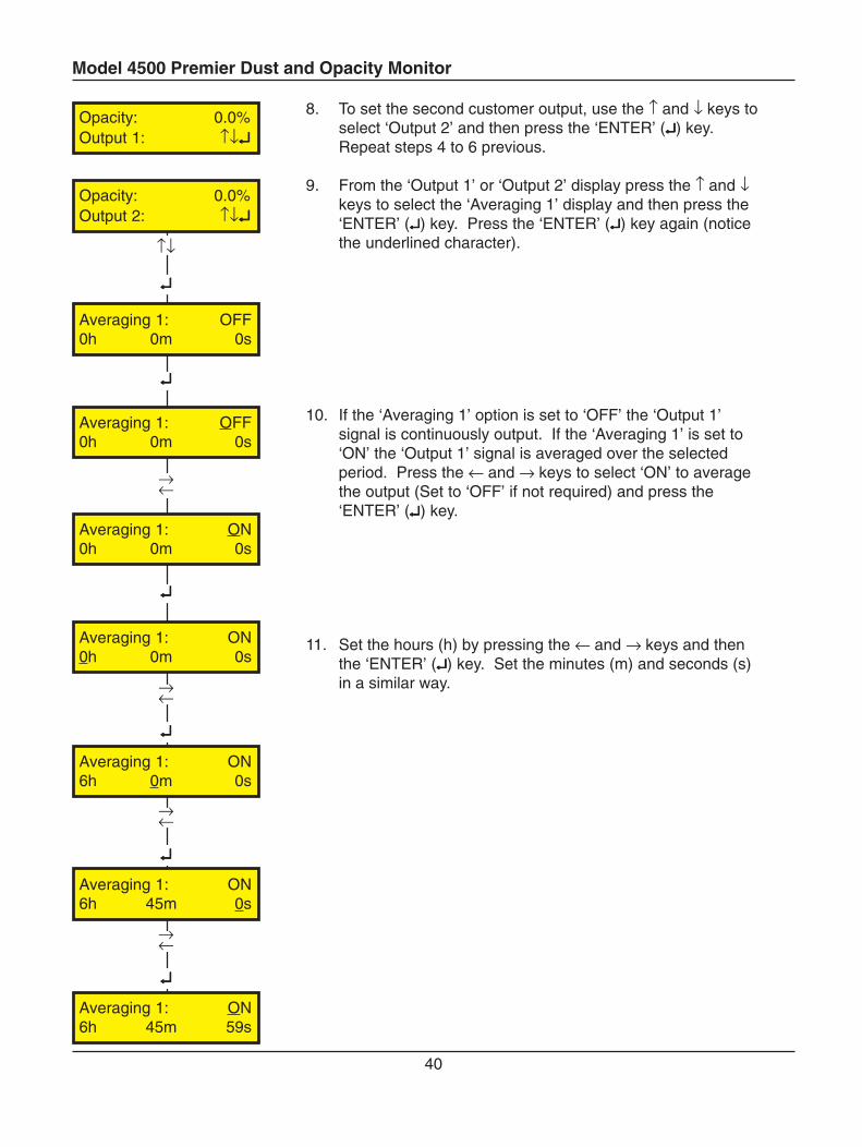
8. To set the second customer output, use the ↑ and ↓ keys toselect ‘Output 2’ and then press the ‘ENTER’ (↵↵↵↵↵) key.Repeat steps 4 to 6 previous.
9. From the ‘Output 1’ or ‘Output 2’ display press the ↑ and ↓keys to select the ‘Averaging 1’ display and then press the‘ENTER’ (↵↵↵↵↵) key. Press the ‘ENTER’ (↵↵↵↵↵) key again (noticethe underlined character).
10. If the ‘Averaging 1’ option is set to ‘OFF’ the ‘Output 1’signal is continuously output. If the ‘Averaging 1’ is set to‘ON’ the ‘Output 1’ signal is averaged over the selectedperiod. Press the ← and → keys to select ‘ON’ to averagethe output (Set to ‘OFF’ if not required) and press the‘ENTER’ (↵↵↵↵↵) key.
11. Set the hours (h) by pressing the ← and → keys and thenthe ‘ENTER’ (↵↵↵↵↵) key. Set the minutes (m) and seconds (s)in a similar way.
↵↵↵↵↵
→←
↵↵↵↵↵
↑↓
↵↵↵↵↵
↵↵↵↵↵
Opacity: 0.0%Output 1: ↑↓↵↵↵↵↵
→←
Opacity: 0.0%Output 2: ↑↓↵↵↵↵↵
Averaging 1: OFF0h 0m 0s
Averaging 1: OFF0h 0m 0s
Averaging 1: ON0h 0m 0s
↵↵↵↵↵
→←
↵↵↵↵↵
→←
Averaging 1: ON0h 0m 0s
Averaging 1: ON6h 0m 0s
Averaging 1: ON6h 45m 0s
Averaging 1: ON6h 45m 59s
Model 4500 Premier Dust and Opacity Monitor
41
EXIT
EXIT
EXIT
↵↵↵↵↵
↵↵↵↵↵
↑↓
Averaging 1: ON6h 45m 59s
Opacity: 0.0%Averaging 1: ↑↓↵↵↵↵↵
Opacity: 0.0%Averaging 2: ↑↓↵↵↵↵↵
Averaging 2: ON6h 45m 59s
Opacity: 0.0%Setup: ↑↓↵↵↵↵↵
Opacity: 0.0%Outputs: ↑↓↵↵↵↵↵
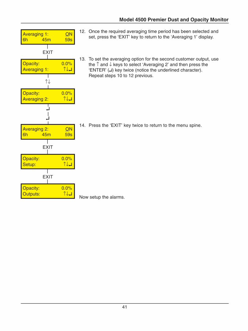
12. Once the required averaging time period has been selected andset, press the ‘EXIT’ key to return to the ‘Averaging 1’ display.
13. To set the averaging option for the second customer output, usethe ↑ and ↓ keys to select ‘Averaging 2’ and then press the‘ENTER’ (↵↵↵↵↵) key twice (notice the underlined character).Repeat steps 10 to 12 previous.
14. Press the ‘EXIT’ key twice to return to the menu spine.
Now setup the alarms.
Model 4500 Premier Dust and Opacity Monitor
42
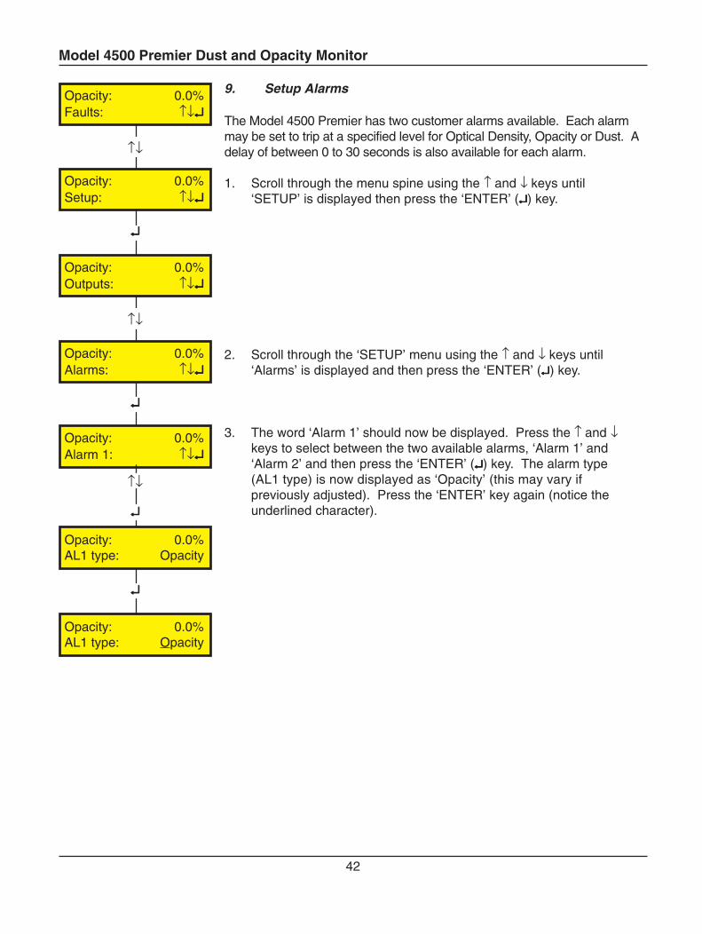
9. Setup Alarms
The Model 4500 Premier has two customer alarms available. Each alarmmay be set to trip at a specified level for Optical Density, Opacity or Dust. Adelay of between 0 to 30 seconds is also available for each alarm.
1. Scroll through the menu spine using the ↑ and ↓ keys until‘SETUP’ is displayed then press the ‘ENTER’ (↵↵↵↵↵) key.
2. Scroll through the ‘SETUP’ menu using the ↑ and ↓ keys until‘Alarms’ is displayed and then press the ‘ENTER’ (↵↵↵↵↵) key.
3. The word ‘Alarm 1’ should now be displayed. Press the ↑ and ↓keys to select between the two available alarms, ‘Alarm 1’ and‘Alarm 2’ and then press the ‘ENTER’ (↵↵↵↵↵) key. The alarm type(AL1 type) is now displayed as ‘Opacity’ (this may vary ifpreviously adjusted). Press the ‘ENTER’ key again (notice theunderlined character).
↑↓
↑↓
↵↵↵↵↵
↵↵↵↵↵
Opacity: 0.0%Faults: ↑↓↵↵↵↵↵
Opacity: 0.0%Setup: ↑↓↵↵↵↵↵
Opacity: 0.0%Outputs: ↑↓↵↵↵↵↵
Opacity: 0.0%Alarms: ↑↓↵↵↵↵↵
Opacity: 0.0%Alarm 1: ↑↓↵↵↵↵↵
↵↵↵↵↵
↑↓
↵↵↵↵↵
Opacity: 0.0%AL1 type: Opacity
Opacity: 0.0%AL1 type: Opacity
Model 4500 Premier Dust and Opacity Monitor
43
↵↵↵↵↵
↑↓
↵↵↵↵↵
↑↓
↵↵↵↵↵
↑↓
↵↵↵↵↵
↑↓
↵↵↵↵↵
→←
EXIT
Opacity: 0.0%AL1 type: Opacity
Opacity: 0.0%AL1 type: O.D.
Opacity: 0.0%AL1 trip: 0.00
Opacity: 0.0%AL1 trip: 15.00
Opacity: 0.0%Delay: 5s
Opacity: 0.0%Delay: 10s
Opacity: 0.0%Alarm 1: ↑↓↵↵↵↵↵
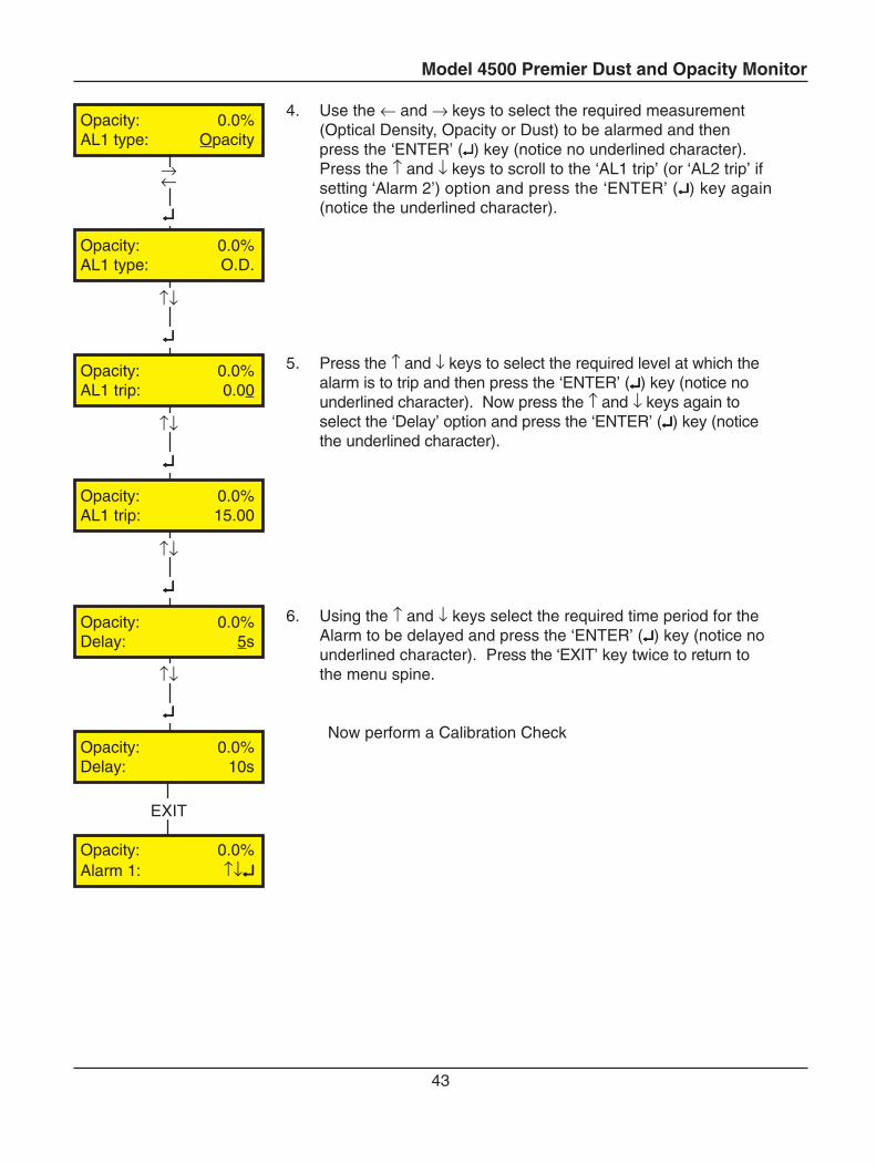
4. Use the ← and → keys to select the required measurement(Optical Density, Opacity or Dust) to be alarmed and thenpress the ‘ENTER’ (↵↵↵↵↵) key (notice no underlined character).Press the ↑ and ↓ keys to scroll to the ‘AL1 trip’ (or ‘AL2 trip’ ifsetting ‘Alarm 2’) option and press the ‘ENTER’ (↵↵↵↵↵) key again(notice the underlined character).
5. Press the ↑ and ↓ keys to select the required level at which thealarm is to trip and then press the ‘ENTER’ (↵↵↵↵↵) key (notice nounderlined character). Now press the ↑ and ↓ keys again toselect the ‘Delay’ option and press the ‘ENTER’ (↵↵↵↵↵) key (noticethe underlined character).
6. Using the ↑ and ↓ keys select the required time period for theAlarm to be delayed and press the ‘ENTER’ (↵↵↵↵↵) key (notice nounderlined character). Press the ‘EXIT’ key twice to return tothe menu spine.
Now perform a Calibration Check
Model 4500 Premier Dust and Opacity Monitor
44
10 Perform Calibration Check
The instrument will be ready for use on completion of ‘Cal check’. The simplest way to perform this isas follows:
1. Power down the instrument.
2. Power up the instrument and a calibration check will be performed automatically.
3. Allow three minutes for the calibration check to be completed and then check that the‘System OK’ LED is on.
4. The Model 4500 Premier is now in operation.
NOTE
If averaged outputs have been set, the current loop outputs will initially read zero until thefirst averaging period is complete.
If the MODBUS option is used continue with setup, otherwise, the instrument is ready for operation.
Model 4500 Premier Dust and Opacity Monitor
45
232
485
Troubleshooting
If problems arise when setting up the Modbus communications then go through the following checklist.
1. Check the Station number is ‘1’ and the ‘Link Not Fitted’ are correct in the instrument settings.2. If you are using RS232 and one LED is permanently ON, then check the selector switch is in the‘Up’ position.3. If you are using RS485 and no LEDs are ON, then check the selector switch is in the ‘Down’position.
IMPORTANT
Modbus communications are not possible when the instrument is in unlocked.
11 MODBUS Option
MODBUS is a communications system based on the RS232 or RS485 duplex hardware standards andprovides direct access to the Model 4500 Premier system data via the Termination Box. It is astandard feature on this model. Details are available from the Modbus website www.modbus.org.
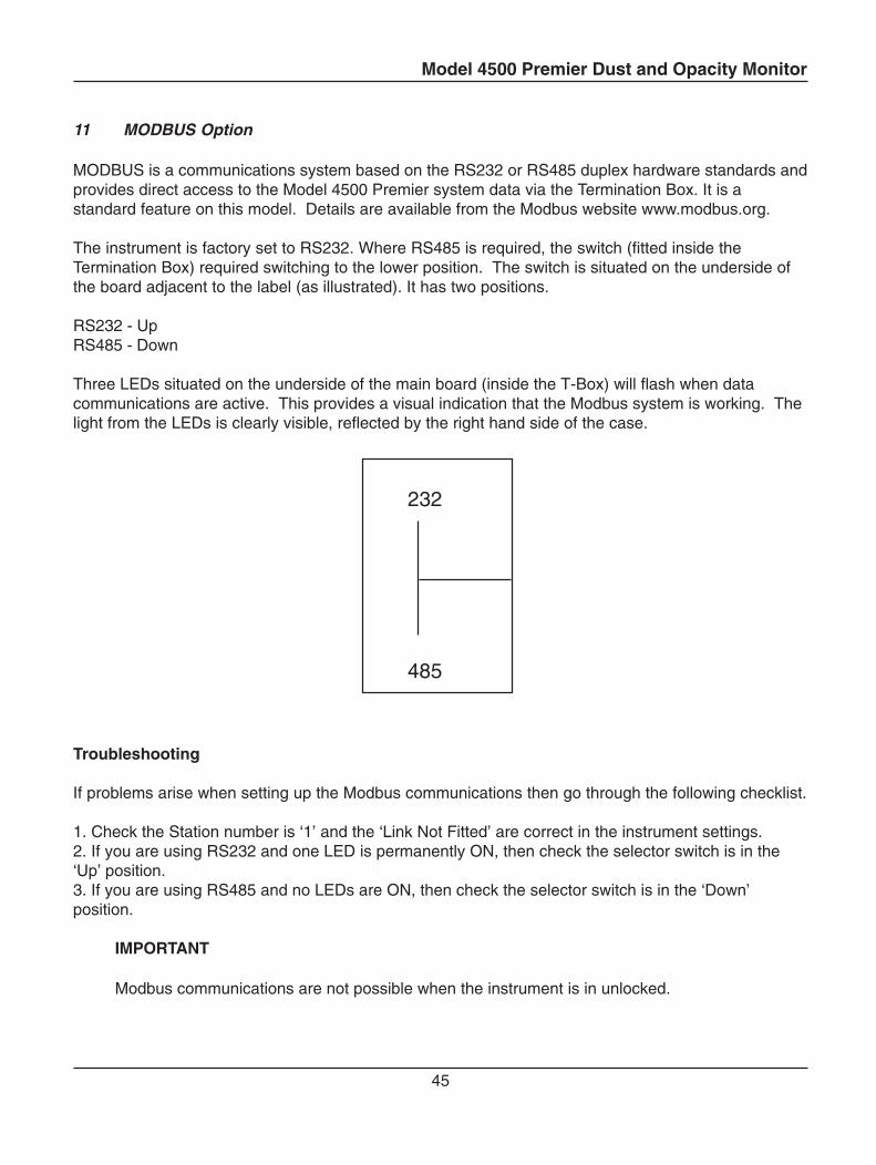
The instrument is factory set to RS232. Where RS485 is required, the switch (fitted inside theTermination Box) required switching to the lower position. The switch is situated on the underside ofthe board adjacent to the label (as illustrated). It has two positions.
RS232 - UpRS485 - Down
Three LEDs situated on the underside of the main board (inside the T-Box) will flash when datacommunications are active. This provides a visual indication that the Modbus system is working. Thelight from the LEDs is clearly visible, reflected by the right hand side of the case.
Model 4500 Premier Dust and Opacity Monitor
46
↑↓
↑↓
↵↵↵↵↵
↵↵↵↵↵
↑↓
↵↵↵↵↵
Opacity: 0.0%Faults: ↑↓↵↵↵↵↵
Opacity: 0.0%Setup: ↑↓↵↵↵↵↵
Opacity: 0.0%Outputs: ↑↓↵↵↵↵↵
Opacity: 0.0%Miscellaneous: ↑↓↵↵↵↵↵
Opacity: 0.0%Align: ↑↓↵↵↵↵↵
Opacity: 0.0%Station number: x
Opacity: 0.0%Station number: x
Setup Menu MODBUS Options
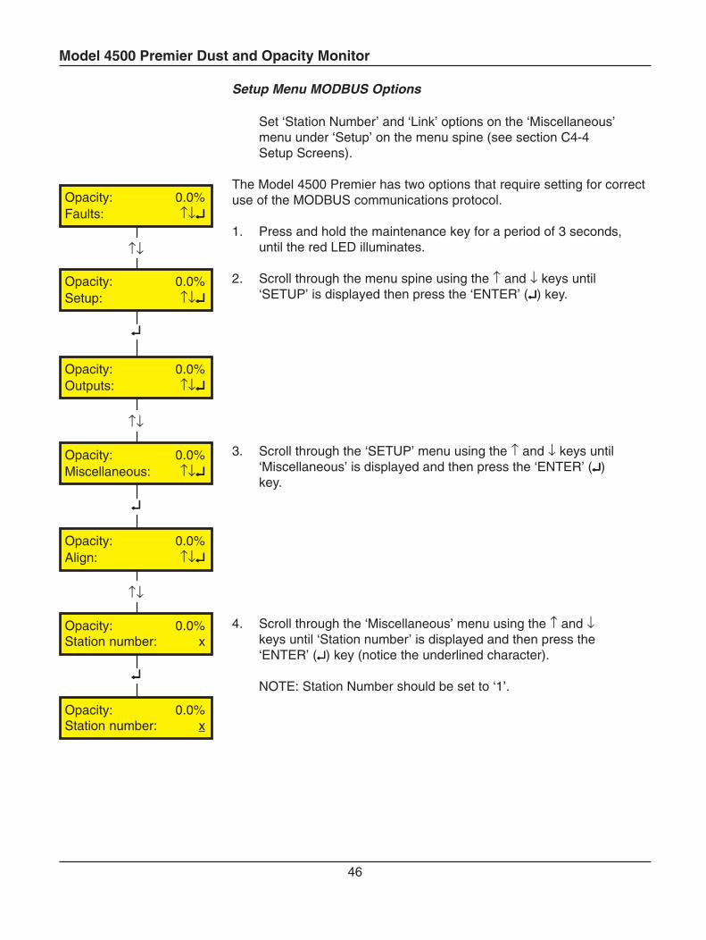
Set ‘Station Number’ and ‘Link’ options on the ‘Miscellaneous’menu under ‘Setup’ on the menu spine (see section C4-4Setup Screens).
The Model 4500 Premier has two options that require setting for correctuse of the MODBUS communications protocol.
1. Press and hold the maintenance key for a period of 3 seconds,until the red LED illuminates.
2. Scroll through the menu spine using the ↑ and ↓ keys until‘SETUP’ is displayed then press the ‘ENTER’ (↵↵↵↵↵) key.
3. Scroll through the ‘SETUP’ menu using the ↑ and ↓ keys until‘Miscellaneous’ is displayed and then press the ‘ENTER’ (↵↵↵↵↵)key.
4. Scroll through the ‘Miscellaneous’ menu using the ↑ and ↓keys until ‘Station number’ is displayed and then press the‘ENTER’ (↵↵↵↵↵) key (notice the underlined character).
NOTE: Station Number should be set to ‘1’.
Model 4500 Premier Dust and Opacity Monitor
47
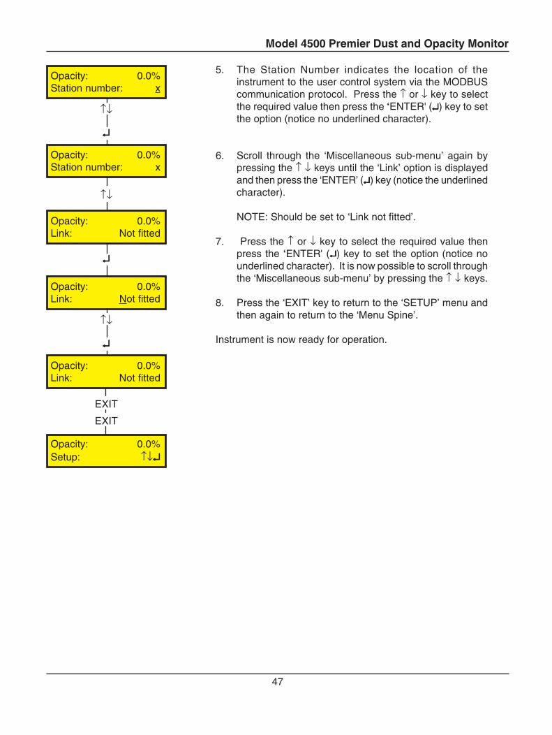
5. The Station Number indicates the location of theinstrument to the user control system via the MODBUScommunication protocol. Press the ↑ or ↓ key to selectthe required value then press the ‘ENTER' (↵↵↵↵↵) key to setthe option (notice no underlined character).
6. Scroll through the ‘Miscellaneous sub-menu’ again bypressing the ↑ ↓ keys until the ‘Link’ option is displayedand then press the ‘ENTER’ (↵↵↵↵↵) key (notice the underlinedcharacter).
NOTE: Should be set to ‘Link not fitted’.
7. Press the ↑ or ↓ key to select the required value thenpress the ‘ENTER' (↵↵↵↵↵) key to set the option (notice nounderlined character). It is now possible to scroll throughthe ‘Miscellaneous sub-menu’ by pressing the ↑ ↓ keys.
8. Press the ‘EXIT’ key to return to the ‘SETUP’ menu andthen again to return to the ‘Menu Spine’.
Instrument is now ready for operation.
EXIT
EXIT
↵↵↵↵↵
↑↓
↑↓
↵↵↵↵↵
↵↵↵↵↵
↑↓
Opacity: 0.0%Station number: x
Opacity: 0.0%Station number: x
Opacity: 0.0%Link: Not fitted
Opacity: 0.0%Link: Not fitted
Opacity: 0.0%Link: Not fitted
Opacity: 0.0%Setup: ↑↓↵↵↵↵↵
Model 4500 Premier Dust and Opacity Monitor
48
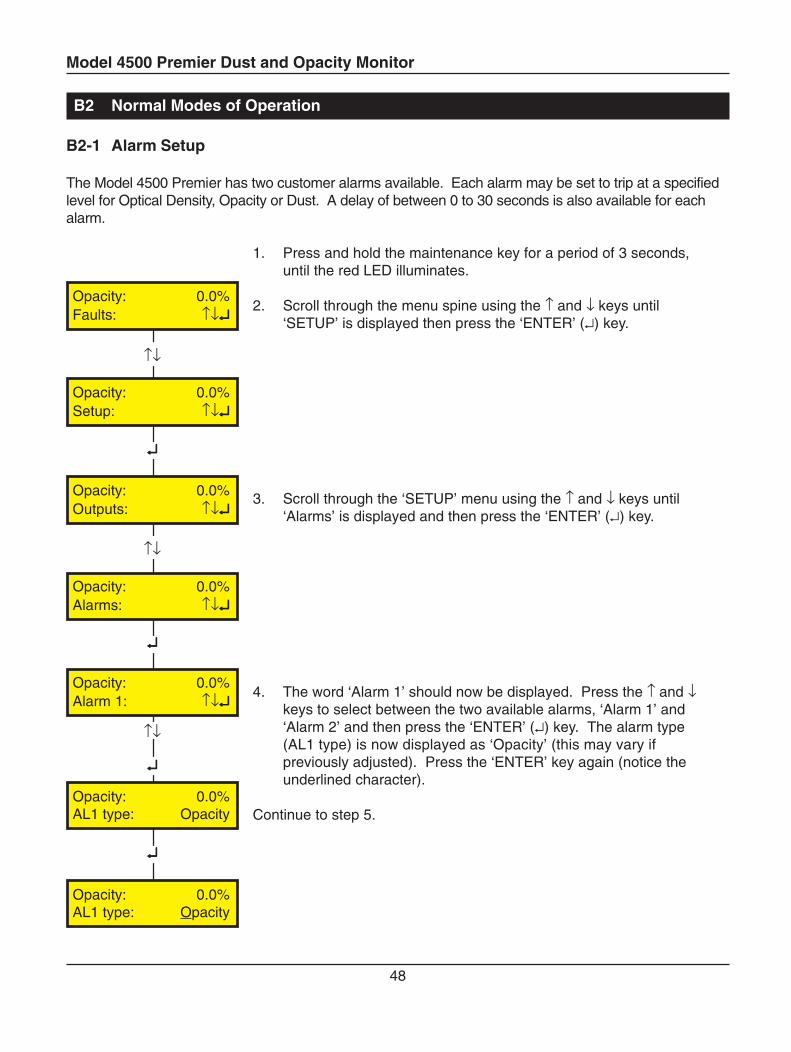
1. Press and hold the maintenance key for a period of 3 seconds,until the red LED illuminates.
2. Scroll through the menu spine using the ↑ and ↓ keys until‘SETUP’ is displayed then press the ‘ENTER’ (↵) key.
3. Scroll through the ‘SETUP’ menu using the ↑ and ↓ keys until‘Alarms’ is displayed and then press the ‘ENTER’ (↵) key.
4. The word ‘Alarm 1’ should now be displayed. Press the ↑ and ↓keys to select between the two available alarms, ‘Alarm 1’ and‘Alarm 2’ and then press the ‘ENTER’ (↵) key. The alarm type(AL1 type) is now displayed as ‘Opacity’ (this may vary ifpreviously adjusted). Press the ‘ENTER’ key again (notice theunderlined character).
Continue to step 5.
B2 Normal Modes of Operation
B2-1 Alarm Setup
The Model 4500 Premier has two customer alarms available. Each alarm may be set to trip at a specifiedlevel for Optical Density, Opacity or Dust. A delay of between 0 to 30 seconds is also available for eachalarm.
↑↓
↵↵↵↵↵
↵↵↵↵↵
↵↵↵↵↵
↑↓
↵↵↵↵↵
↑↓
Opacity: 0.0%Faults: ↑↓↵↵↵↵↵
Opacity: 0.0%Setup: ↑↓↵↵↵↵↵
Opacity: 0.0%Outputs: ↑↓↵↵↵↵↵
Opacity: 0.0%Alarms: ↑↓↵↵↵↵↵
Opacity: 0.0%Alarm 1: ↑↓↵↵↵↵↵
Opacity: 0.0%AL1 type: Opacity
Opacity: 0.0%AL1 type: Opacity
Model 4500 Premier Dust and Opacity Monitor
49
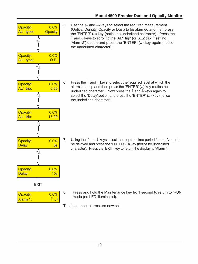
5. Use the ← and → keys to select the required measurement(Optical Density, Opacity or Dust) to be alarmed and then pressthe ‘ENTER’ (↵) key (notice no underlined character). Press the↑ and ↓ keys to scroll to the ‘AL1 trip’ (or ‘AL2 trip’ if setting‘Alarm 2’) option and press the ‘ENTER’ (↵) key again (noticethe underlined character).
6. Press the ↑ and ↓ keys to select the required level at which thealarm is to trip and then press the ‘ENTER’ (↵) key (notice nounderlined character). Now press the ↑ and ↓ keys again toselect the ‘Delay’ option and press the ‘ENTER’ (↵) key (noticethe underlined character).
7. Using the ↑ and ↓ keys select the required time period for the Alarm tobe delayed and press the ‘ENTER’ (↵) key (notice no underlinedcharacter). Press the ‘EXIT’ key to return the display to ‘Alarm 1’.
8. Press and hold the Maintenance key fro 1 second to return to ‘RUN’mode (no LED illuminated).
The instrument alarms are now set.
↵↵↵↵↵
→←
↵↵↵↵↵
↑↓
↵↵↵↵↵
↑↓
↵↵↵↵↵
↑↓
↵↵↵↵↵
↑↓
EXIT
Opacity: 0.0%AL1 type: Opacity
Opacity: 0.0%AL1 type: O.D.
Opacity: 0.0%AL1 trip: 0.00
Opacity: 0.0%AL1 trip: 15.00
Opacity: 0.0%Delay: 5s
Opacity: 0.0%Delay: 10s
Opacity: 0.0%Alarm 1: ↑↓↵↵↵↵↵
Model 4500 Premier Dust and Opacity Monitor
50
↑↓
↵↵↵↵↵
↵↵↵↵↵
↵↵↵↵↵
↵↵↵↵↵
B2-2 Output Setup
Opacity: 0.0%Faults: ↑↓↵↵↵↵↵
Opacity: 0.0%Setup: ↑↓↵↵↵↵↵
Opacity: 0.0%Outputs: ↑↓↵↵↵↵↵
Opacity: 0.0%Output 1: ↑↓↵↵↵↵↵
Outputs 1: ↑↓↵↵↵↵↵Opacity
Outputs 1: ↔↵↵↵↵↵Opacity
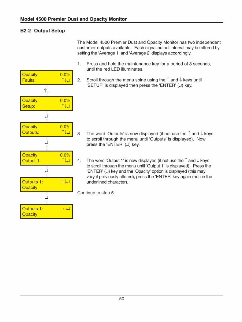
The Model 4500 Premier Dust and Opacity Monitor has two independentcustomer outputs available. Each signal output interval may be altered bysetting the ‘Average 1’ and ‘Average 2’ displays accordingly.
1. Press and hold the maintenance key for a period of 3 seconds,until the red LED illuminates.
2. Scroll through the menu spine using the ↑ and ↓ keys until‘SETUP’ is displayed then press the ‘ENTER’ (↵) key.
3. The word ‘Outputs’ is now displayed (if not use the ↑ and ↓ keysto scroll through the menu until ‘Outputs’ is displayed). Nowpress the ‘ENTER’ (↵) key.
4. The word ‘Output 1’ is now displayed (if not use the ↑ and ↓ keysto scroll through the menu until ‘Output 1’ is displayed). Press the‘ENTER’ (↵) key and the ‘Opacity’ option is displayed (this mayvary if previously altered), press the ‘ENTER’ key again (notice theunderlined character).
Continue to step 5.
Model 4500 Premier Dust and Opacity Monitor
51
↵↵↵↵↵
↑↓
↵↵↵↵↵
↑↓
↵↵↵↵↵
→←
EXIT
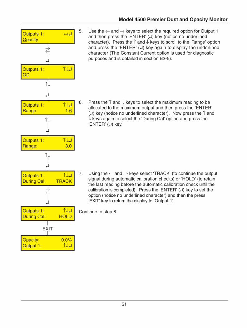
5. Use the ← and → keys to select the required option for Output 1and then press the ‘ENTER’ (↵) key (notice no underlinedcharacter). Press the ↑ and ↓ keys to scroll to the ‘Range’ optionand press the ‘ENTER’ (↵) key again to display the underlinedcharacter (The Constant Current option is used for diagnosticpurposes and is detailed in section B2-5).
6. Press the ↑ and ↓ keys to select the maximum reading to beallocated to the maximum output and then press the ‘ENTER’(↵) key (notice no underlined character). Now press the ↑ and↓ keys again to select the ‘During Cal’ option and press the‘ENTER’ (↵) key.
7. Using the ← and → keys select ‘TRACK’ (to continue the outputsignal during automatic calibration checks) or ‘HOLD’ (to retainthe last reading before the automatic calibration check until thecalibration is completed). Press the ‘ENTER’ (↵) key to set theoption (notice no underlined character) and then the press‘EXIT’ key to return the display to ‘Output 1’.
Continue to step 8.
Outputs 1: ↑↓↵↵↵↵↵Range: 3.0
Outputs 1: ↑↓↵↵↵↵↵During Cal: TRACK
Outputs 1: ↑↓↵↵↵↵↵During Cal: HOLD
Opacity: 0.0%Output 1: ↑↓↵↵↵↵↵
↵↵↵↵↵
→←
↵↵↵↵↵
↑↓
Outputs 1: ↔↵↵↵↵↵Opacity
Outputs 1: ↑↓↵↵↵↵↵OD
Outputs 1: ↑↓↵↵↵↵↵Range: 1.6
Model 4500 Premier Dust and Opacity Monitor
52
↵↵↵↵↵
↑↓
↵↵↵↵↵
↵↵↵↵↵
→←
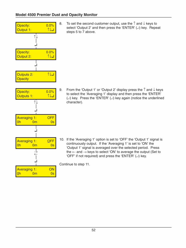
8. To set the second customer output, use the ↑ and ↓ keys toselect ‘Output 2’ and then press the ‘ENTER’ (↵) key. Repeatsteps 5 to 7 above.
9. From the ‘Output 1’ or ‘Output 2’ display press the ↑ and ↓ keysto select the ‘Averaging 1’ display and then press the ‘ENTER’(↵) key. Press the ‘ENTER’ (↵) key again (notice the underlinedcharacter).
10. If the ‘Averaging 1’ option is set to ‘OFF’ the ‘Output 1’ signal iscontinuously output. If the ‘Averaging 1’ is set to ‘ON’ the‘Output 1’ signal is averaged over the selected period. Pressthe ← and → keys to select ‘ON’ to average the output (Set to‘OFF’ if not required) and press the ‘ENTER’ (↵) key.
Continue to step 11.
Averaging 1: OFF0h 0m 0s
Averaging 1: OFF0h 0m 0s
Averaging 1: ON0h 0m 0s
↵↵↵↵↵
↑↓
↵↵↵↵↵
Opacity: 0.0%Output 1: ↑↓↵↵↵↵↵
Opacity: 0.0%Output 2: ↑↓↵↵↵↵↵
Opacity: 0.0%Outputs 1: ↑↓↵↵↵↵↵
Outputs 2: ↑↓↵↵↵↵↵Opacity
Model 4500 Premier Dust and Opacity Monitor
53
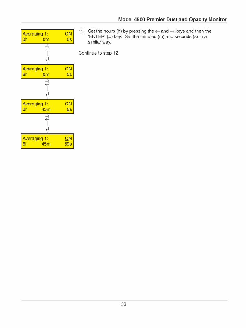
11. Set the hours (h) by pressing the ← and → keys and then the‘ENTER’ (↵) key. Set the minutes (m) and seconds (s) in asimilar way.
Continue to step 12
↵↵↵↵↵
→←
↵↵↵↵↵
→←
↵↵↵↵↵
→←
Averaging 1: ON0h 0m 0s
Averaging 1: ON6h 45m 0s
Averaging 1: ON6h 0m 0s
Averaging 1: ON6h 45m 59s
Model 4500 Premier Dust and Opacity Monitor
54
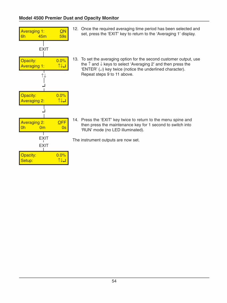
12. Once the required averaging time period has been selected andset, press the ‘EXIT’ key to return to the ‘Averaging 1’ display.
13. To set the averaging option for the second customer output, usethe ↑ and ↓ keys to select ‘Averaging 2’ and then press the‘ENTER’ (↵) key twice (notice the underlined character).Repeat steps 9 to 11 above.
14. Press the ‘EXIT’ key twice to return to the menu spine andthen press the maintenance key for 1 second to switch into‘RUN’ mode (no LED illuminated).
The instrument outputs are now set.EXIT
EXIT
↵↵↵↵↵
EXIT
↵↵↵↵↵
↑↓
Averaging 1: ON6h 45m 59s
Opacity: 0.0%Averaging 1: ↑↓↵↵↵↵↵
Opacity: 0.0%Averaging 2: ↑↓↵↵↵↵↵
Averaging 2: OFF0h 0m 0s
Opacity: 0.0%Setup: ↑↓↵↵↵↵↵
Model 4500 Premier Dust and Opacity Monitor
55
B2-3 MODBUS Communications
MODBUS is a communications system based on the RS232/RS485 three wire half duplex hardwarestandard and provides direct access to the Model 4500 Premier system data via the instrument serialport. MODBUS can be used to:
a) read any of the parameters measured by the Instrumentb) check the instrument statusc) initiate a check cycle calibration
NOTE
Changing the calibration constants may fundamentally affect the operation of the instrument.
The instrument functions as a MODBUS slave device in accordance with the MODBUS protocol (asdefined by Modicon)
Details of the MODBUS standard are available at www.modbus.org.
Before communicating with Model 4500 Premier via the MODBUS interface, it is necessary to set the‘Station No.’ (the MODBUS slave address) and the ‘Link’ options to an appropriate value. The twooptions are located in the ‘Miscellaneous’ menu under ‘Setup’ on the menu spine (see Setup Screenssection C4-4).
The system data for the Model 4500 Premier is accessible via register numbers as shown on the‘System Data Register Table’ shown in this section.
NOTE
There is a possible source of confusion in the definition of “Register Numbers” used inMODBUS functions. For historical reasons, user reference numbers are expressed asdecimal numbers with a starting offset of 1; so a Modbus message requesting a read atAddress Offset 0 would return the value in Register 1. The System Data Register Tablegiven uses Register Numbers rather than address offsets.
Model 4500 Premier Dust and Opacity Monitor
56
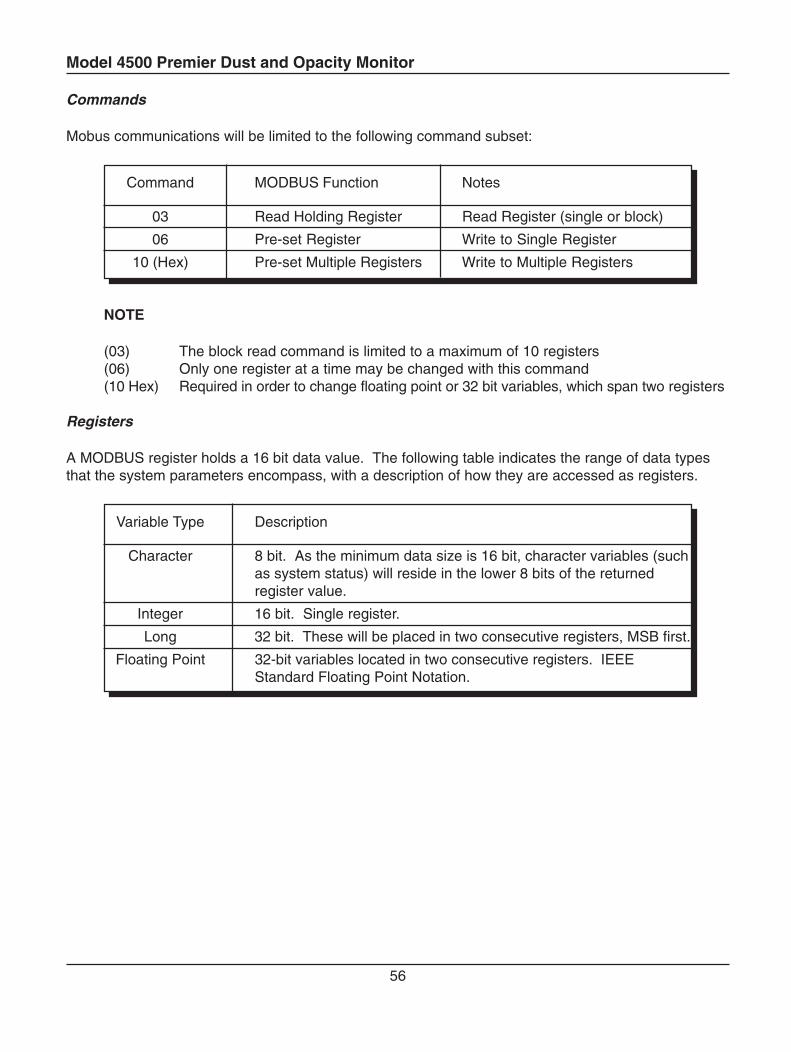
Commands
Mobus communications will be limited to the following command subset:
Command MODBUS Function Notes
03 Read Holding Register Read Register (single or block)
06 Pre-set Register Write to Single Register
10 (Hex) Pre-set Multiple Registers Write to Multiple Registers
NOTE
(03) The block read command is limited to a maximum of 10 registers(06) Only one register at a time may be changed with this command(10 Hex) Required in order to change floating point or 32 bit variables, which span two registers
Registers
A MODBUS register holds a 16 bit data value. The following table indicates the range of data typesthat the system parameters encompass, with a description of how they are accessed as registers.
Variable Type Description
Character 8 bit. As the minimum data size is 16 bit, character variables (suchas system status) will reside in the lower 8 bits of the returnedregister value.
Integer 16 bit. Single register.
Long 32 bit. These will be placed in two consecutive registers, MSB first.
Floating Point 32-bit variables located in two consecutive registers. IEEEStandard Floating Point Notation.
Model 4500 Premier Dust and Opacity Monitor
57
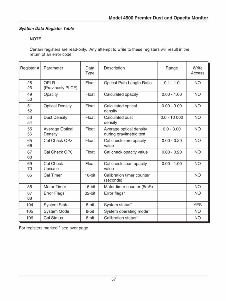
System Data Register Table
NOTE
Certain registers are read-only. Any attempt to write to these registers will result in thereturn of an error code.
Register # Parameter Data Description Range WriteType Access
25 OPLR Float Optical Path Length Ratio 0.1 - 1.0 NO26 (Previously PLCF)
49 Opacity Float Calculated opacity 0.00 - 1.00 NO50
51 Optical Density Float Calculated optical 0.00 - 3.00 NO52 density
53 Dust Density Float Calculated dust 0.0 - 10 000 NO54 density
55 Average Optical Float Average optical density 0.0 - 3.00 NO56 Density during gravimetric test
65 Cal Check OPz Float Cal check zero opacity 0.00 - 0.20 NO66 value
67 Cal Check OP0 Float Cal check opacity value 0.00 - 0.20 NO68
69 Cal Check Float Cal check span opacity 0.00 - 1.00 NO70 Upscale value
85 Cal Timer 16-bit Calibration timer counter NO(seconds)
86 Motor Timer 16-bit Motor timer counter (5mS) NO
87 Error Flags 32-bit Error flags* NO88
104 System State 8-bit System status* YES
105 System Mode 8-bit System operating mode* NO
106 Cal Status 8-bit Calibration status* NO
For registers marked * see over page
Model 4500 Premier Dust and Opacity Monitor
58
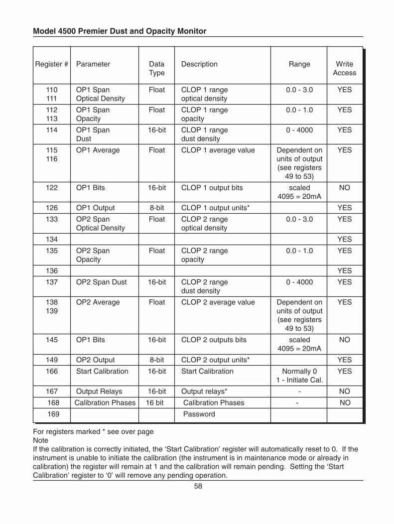
Register # Parameter Data Description Range WriteType Access
110 OP1 Span Float CLOP 1 range 0.0 - 3.0 YES111 Optical Density optical density
112 OP1 Span Float CLOP 1 range 0.0 - 1.0 YES113 Opacity opacity
114 OP1 Span 16-bit CLOP 1 range 0 - 4000 YESDust dust density
115 OP1 Average Float CLOP 1 average value Dependent on YES116 units of output
(see registers49 to 53)
122 OP1 Bits 16-bit CLOP 1 output bits scaled NO4095 = 20mA
126 OP1 Output 8-bit CLOP 1 output units* YES
133 OP2 Span Float CLOP 2 range 0.0 - 3.0 YESOptical Density optical density
134 YES
135 OP2 Span Float CLOP 2 range 0.0 - 1.0 YESOpacity opacity
136 YES
137 OP2 Span Dust 16-bit CLOP 2 range 0 - 4000 YESdust density
138 OP2 Average Float CLOP 2 average value Dependent on YES139 units of output
(see registers49 to 53)
145 OP1 Bits 16-bit CLOP 2 outputs bits scaled NO4095 = 20mA
149 OP2 Output 8-bit CLOP 2 output units* YES
166 Start Calibration 16-bit Start Calibration Normally 0 YES1 - Initiate Cal.
167 Output Relays 16-bit Output relays* - NO
168 Calibration Phases 16 bit Calibration Phases - NO
169 Password
For registers marked * see over pageNoteIf the calibration is correctly initiated, the ‘Start Calibration’ register will automatically reset to 0. If theinstrument is unable to initiate the calibration (the instrument is in maintenance mode or already incalibration) the register will remain at 1 and the calibration will remain pending. Setting the ‘StartCalibration’ register to ‘0’ will remove any pending operation.
Model 4500 Premier Dust and Opacity Monitor
59
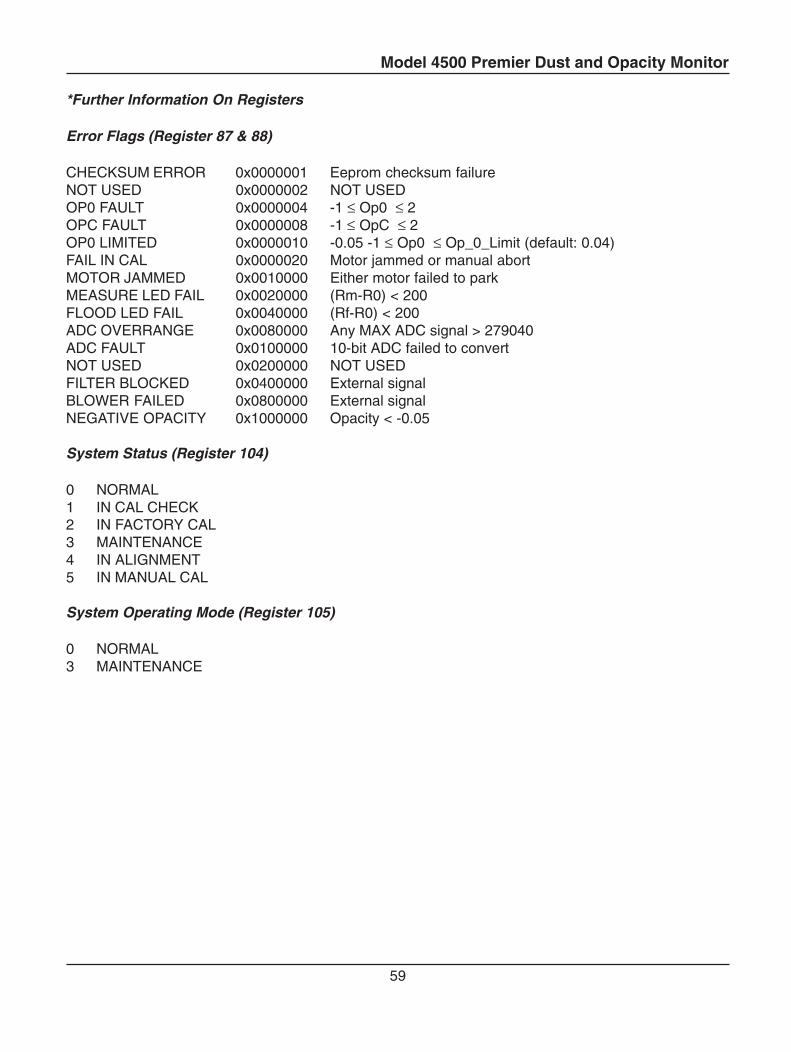
*Further Information On Registers
Error Flags (Register 87 & 88)
CHECKSUM ERROR 0x0000001 Eeprom checksum failureNOT USED 0x0000002 NOT USEDOP0 FAULT 0x0000004 -1 ≤ Op0 ≤ 2OPC FAULT 0x0000008 -1 ≤ OpC ≤ 2OP0 LIMITED 0x0000010 -0.05 -1 ≤ Op0 ≤ Op_0_Limit (default: 0.04)FAIL IN CAL 0x0000020 Motor jammed or manual abortMOTOR JAMMED 0x0010000 Either motor failed to parkMEASURE LED FAIL 0x0020000 (Rm-R0) < 200FLOOD LED FAIL 0x0040000 (Rf-R0) < 200ADC OVERRANGE 0x0080000 Any MAX ADC signal > 279040ADC FAULT 0x0100000 10-bit ADC failed to convertNOT USED 0x0200000 NOT USEDFILTER BLOCKED 0x0400000 External signalBLOWER FAILED 0x0800000 External signalNEGATIVE OPACITY 0x1000000 Opacity < -0.05
System Status (Register 104)
0 NORMAL1 IN CAL CHECK2 IN FACTORY CAL3 MAINTENANCE4 IN ALIGNMENT5 IN MANUAL CAL
System Operating Mode (Register 105)
0 NORMAL3 MAINTENANCE
Model 4500 Premier Dust and Opacity Monitor
60
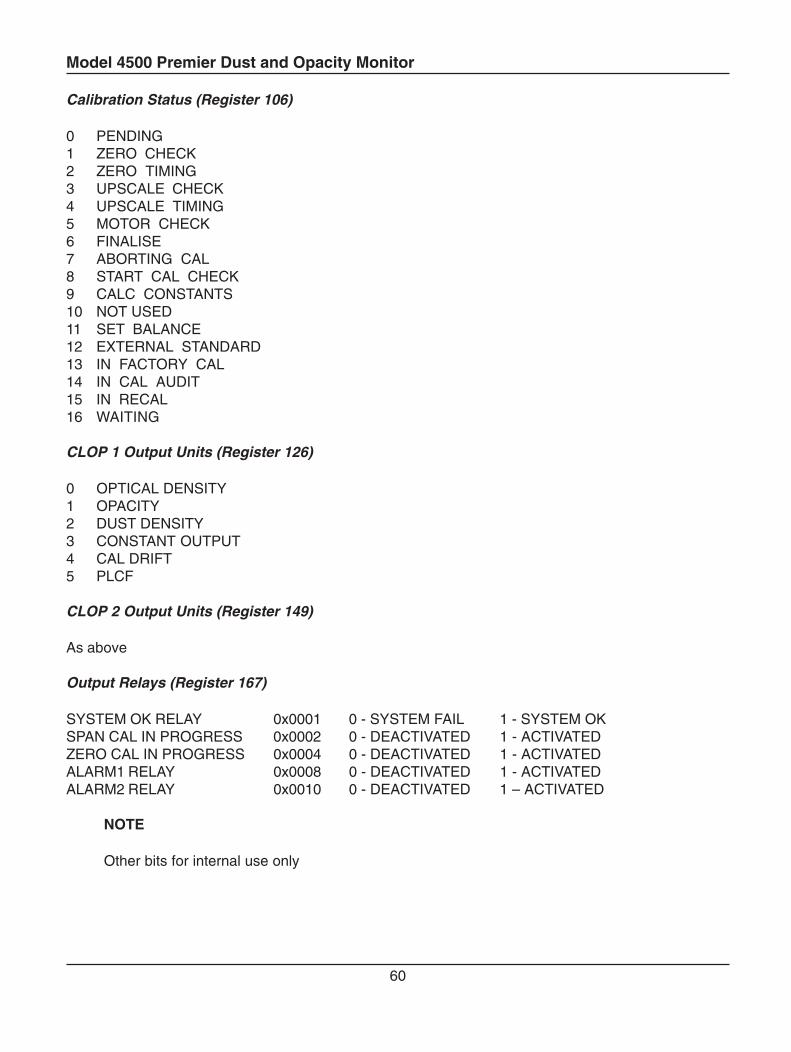
Calibration Status (Register 106)
0 PENDING1 ZERO CHECK2 ZERO TIMING3 UPSCALE CHECK4 UPSCALE TIMING5 MOTOR CHECK6 FINALISE7 ABORTING CAL8 START CAL CHECK9 CALC CONSTANTS10 NOT USED11 SET BALANCE12 EXTERNAL STANDARD13 IN FACTORY CAL14 IN CAL AUDIT15 IN RECAL16 WAITING
CLOP 1 Output Units (Register 126)
0 OPTICAL DENSITY1 OPACITY2 DUST DENSITY3 CONSTANT OUTPUT4 CAL DRIFT5 PLCF
CLOP 2 Output Units (Register 149)
As above
Output Relays (Register 167)
SYSTEM OK RELAY 0x0001 0 - SYSTEM FAIL 1 - SYSTEM OKSPAN CAL IN PROGRESS 0x0002 0 - DEACTIVATED 1 - ACTIVATEDZERO CAL IN PROGRESS 0x0004 0 - DEACTIVATED 1 - ACTIVATEDALARM1 RELAY 0x0008 0 - DEACTIVATED 1 - ACTIVATEDALARM2 RELAY 0x0010 0 - DEACTIVATED 1 – ACTIVATED
NOTE
Other bits for internal use only
Model 4500 Premier Dust and Opacity Monitor
61
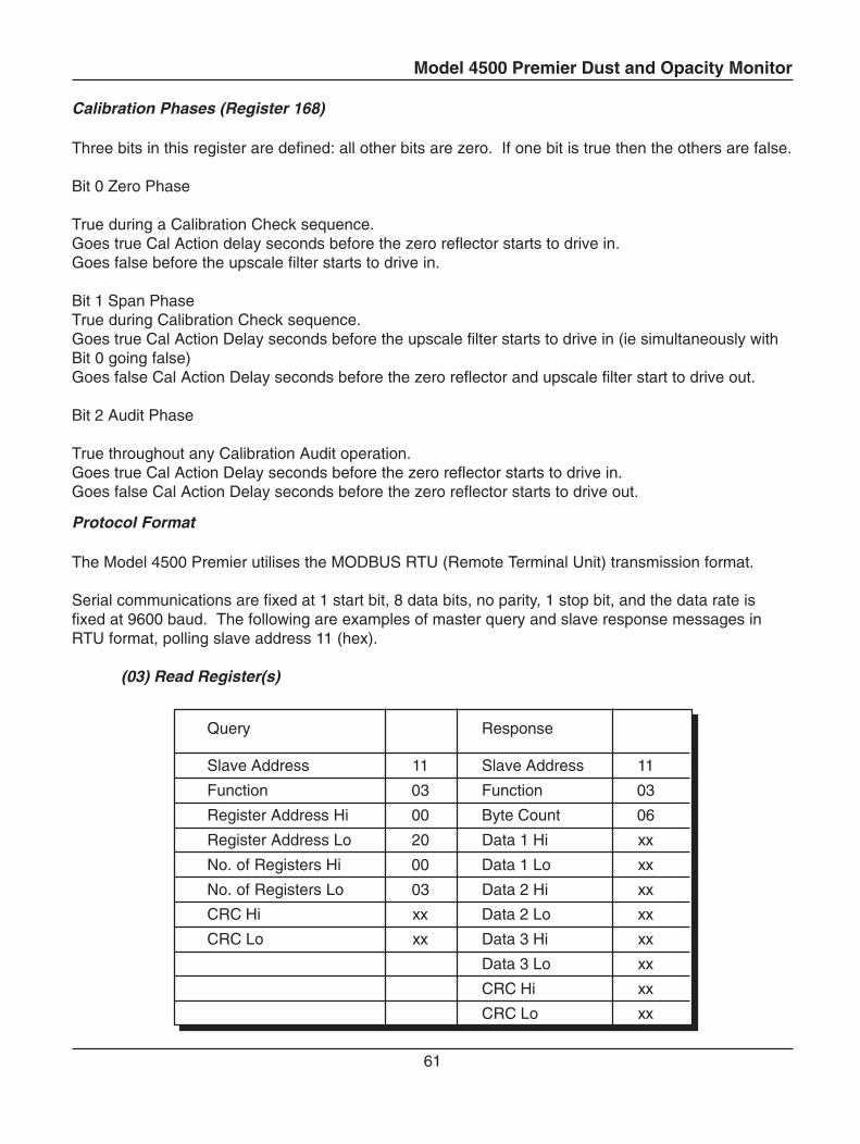
Protocol Format
The Model 4500 Premier utilises the MODBUS RTU (Remote Terminal Unit) transmission format.
Serial communications are fixed at 1 start bit, 8 data bits, no parity, 1 stop bit, and the data rate isfixed at 9600 baud. The following are examples of master query and slave response messages inRTU format, polling slave address 11 (hex).
(03) Read Register(s)
Query Response
Slave Address 11 Slave Address 11
Function 03 Function 03
Register Address Hi 00 Byte Count 06
Register Address Lo 20 Data 1 Hi xx
No. of Registers Hi 00 Data 1 Lo xx
No. of Registers Lo 03 Data 2 Hi xx
CRC Hi xx Data 2 Lo xx
CRC Lo xx Data 3 Hi xx
Data 3 Lo xx
CRC Hi xx
CRC Lo xx
Calibration Phases (Register 168)
Three bits in this register are defined: all other bits are zero. If one bit is true then the others are false.
Bit 0 Zero Phase
True during a Calibration Check sequence.Goes true Cal Action delay seconds before the zero reflector starts to drive in.Goes false before the upscale filter starts to drive in.
Bit 1 Span PhaseTrue during Calibration Check sequence.Goes true Cal Action Delay seconds before the upscale filter starts to drive in (ie simultaneously withBit 0 going false)Goes false Cal Action Delay seconds before the zero reflector and upscale filter start to drive out.
Bit 2 Audit Phase
True throughout any Calibration Audit operation.Goes true Cal Action Delay seconds before the zero reflector starts to drive in.Goes false Cal Action Delay seconds before the zero reflector starts to drive out.
Model 4500 Premier Dust and Opacity Monitor
62
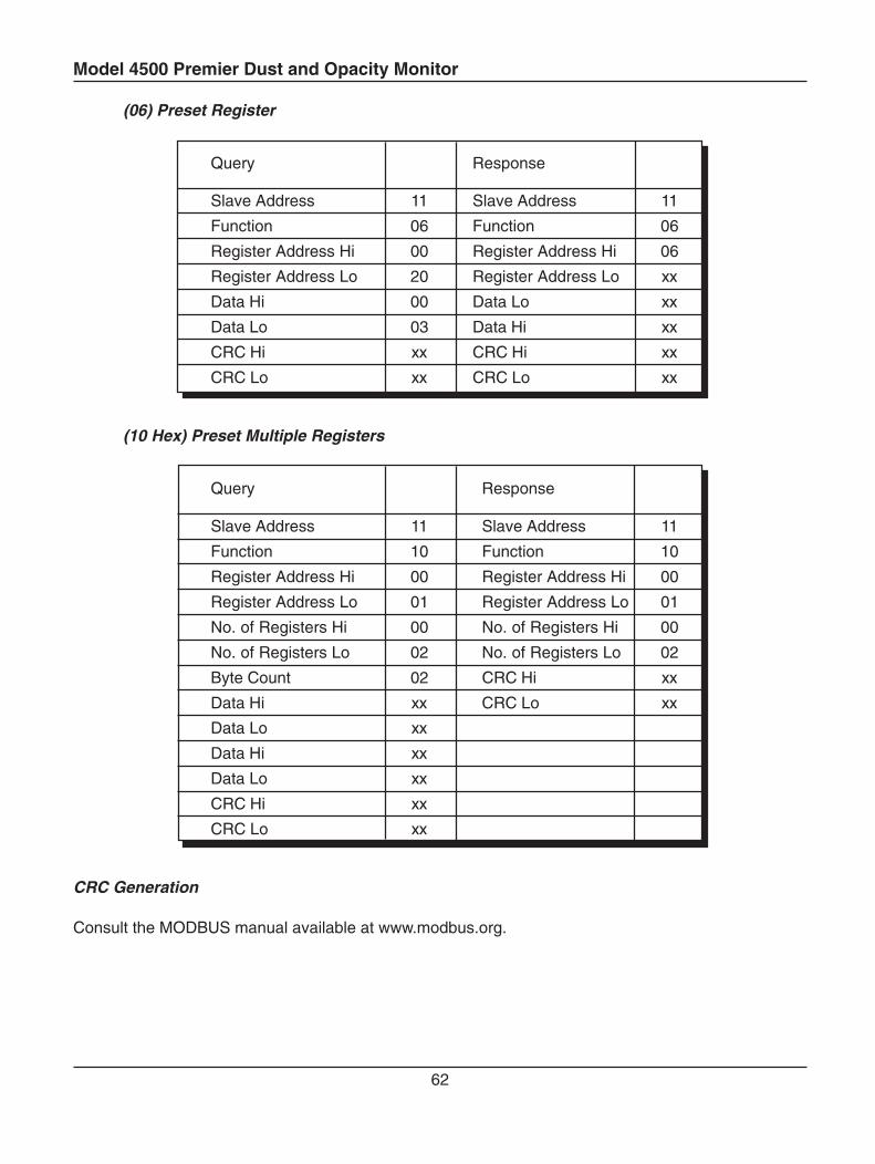
(06) Preset Register
Query Response
Slave Address 11 Slave Address 11
Function 06 Function 06
Register Address Hi 00 Register Address Hi 06
Register Address Lo 20 Register Address Lo xx
Data Hi 00 Data Lo xx
Data Lo 03 Data Hi xx
CRC Hi xx CRC Hi xx
CRC Lo xx CRC Lo xx
(10 Hex) Preset Multiple Registers
Query Response
Slave Address 11 Slave Address 11
Function 10 Function 10
Register Address Hi 00 Register Address Hi 00
Register Address Lo 01 Register Address Lo 01
No. of Registers Hi 00 No. of Registers Hi 00
No. of Registers Lo 02 No. of Registers Lo 02
Byte Count 02 CRC Hi xx
Data Hi xx CRC Lo xx
Data Lo xx
Data Hi xx
Data Lo xx
CRC Hi xx
CRC Lo xx
CRC Generation
Consult the MODBUS manual available at www.modbus.org.
Model 4500 Premier Dust and Opacity Monitor
63
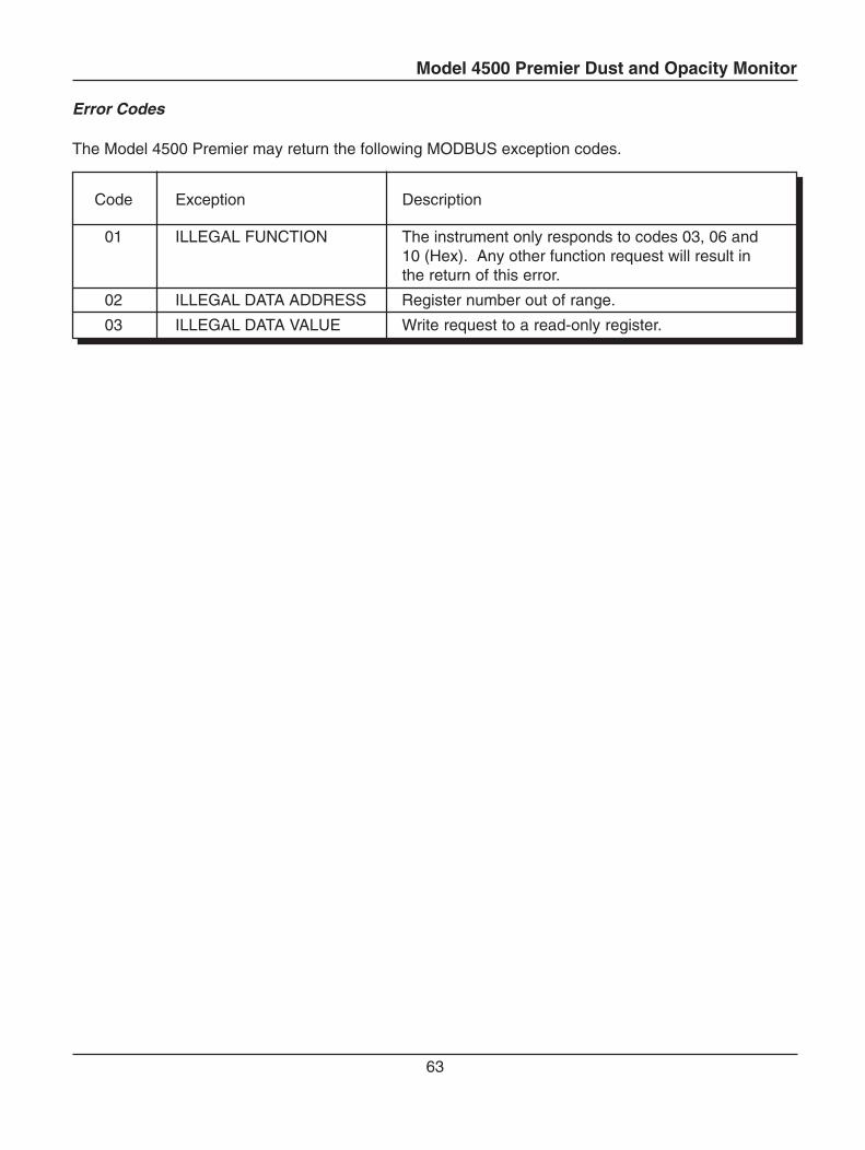
Error Codes
The Model 4500 Premier may return the following MODBUS exception codes.
Code Exception Description
01 ILLEGAL FUNCTION The instrument only responds to codes 03, 06 and10 (Hex). Any other function request will result inthe return of this error.
02 ILLEGAL DATA ADDRESS Register number out of range.
03 ILLEGAL DATA VALUE Write request to a read-only register.
Model 4500 Premier Dust and Opacity Monitor
64
B3 Periodic Modes of Operation
B3-1 Calibration Check
11
1 2 8 9
3 6 7 4
10
5
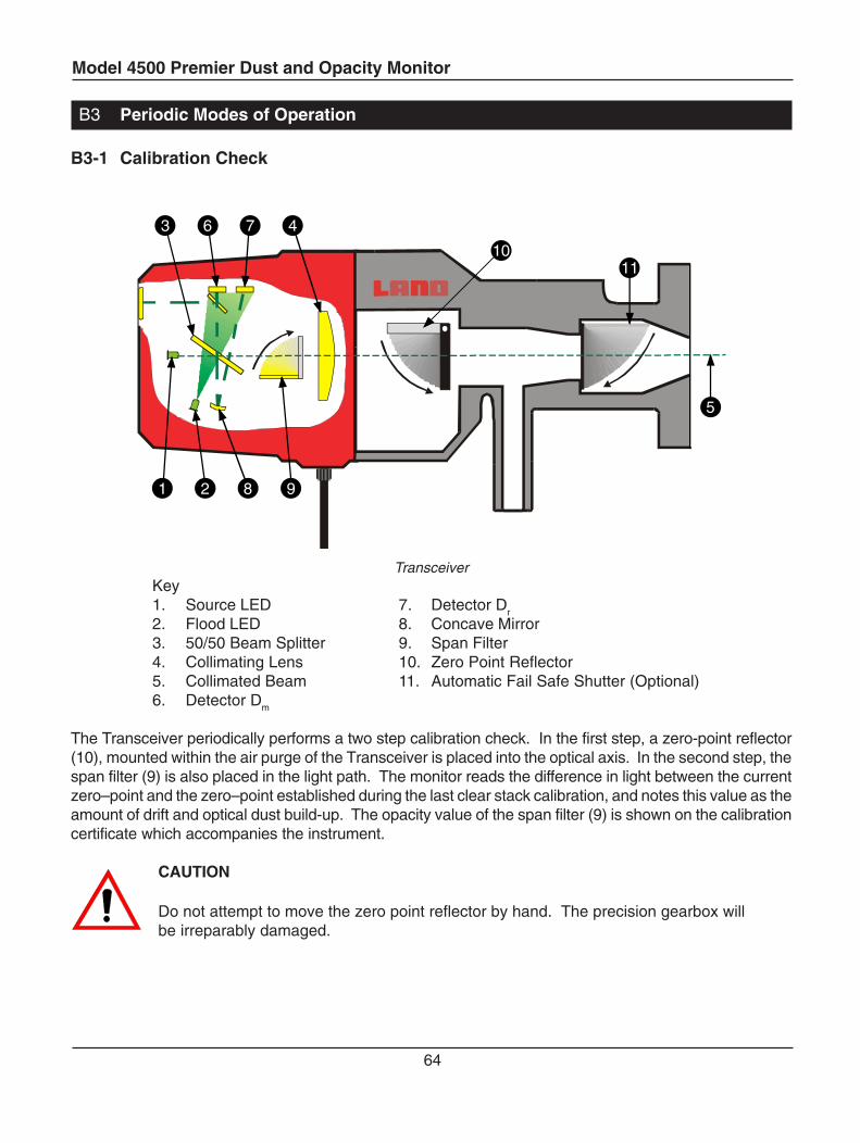
TransceiverKey1. Source LED 7. Detector Dr
2. Flood LED 8. Concave Mirror3. 50/50 Beam Splitter 9. Span Filter4. Collimating Lens 10. Zero Point Reflector5. Collimated Beam 11. Automatic Fail Safe Shutter (Optional)6. Detector Dm
The Transceiver periodically performs a two step calibration check. In the first step, a zero-point reflector(10), mounted within the air purge of the Transceiver is placed into the optical axis. In the second step, thespan filter (9) is also placed in the light path. The monitor reads the difference in light between the currentzero–point and the zero–point established during the last clear stack calibration, and notes this value as theamount of drift and optical dust build-up. The opacity value of the span filter (9) is shown on the calibrationcertificate which accompanies the instrument.
CAUTION
Do not attempt to move the zero point reflector by hand. The precision gearbox willbe irreparably damaged.
Model 4500 Premier Dust and Opacity Monitor
65
B3.2 Calibration Audit
A convenient Calibration Audit facility is provided, for carrying out the Calibration Audit tests required byUSEPA and other Environmental Regulatory Authorities.
Calibration Audit and Modbus Communications
When the instrument is in maintenance mode Modbus communications are disabled. It is therefore notpossible in this mode to monitor the results of the Calibration Audit and Response Time tests using theModbus.
If Modbus communications are required during a Calibration Audit, follow the instructions in CalibrationAudit Method 2.
Calibration Audit Method 1 (Modbus disabled)
1 Press and hold the Maintenance key unit the red LED illuminates (about 5 seconds).
2 Enter the password using the ↑ and ↓ keys, then press the ‘ENTER’ (↵) key. The default passwordis 10.
3 Use the DOWN ARROW key to select Calibration and press ENTER.
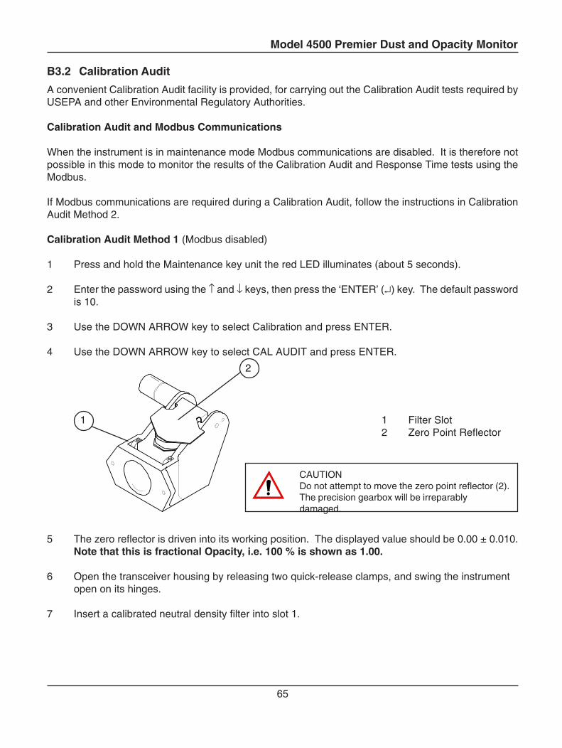
4 Use the DOWN ARROW key to select CAL AUDIT and press ENTER.
5 The zero reflector is driven into its working position. The displayed value should be 0.00 ± 0.010.Note that this is fractional Opacity, i.e. 100 % is shown as 1.00.
6 Open the transceiver housing by releasing two quick-release clamps, and swing the instrumentopen on its hinges.
7 Insert a calibrated neutral density filter into slot 1.
1 Filter Slot2 Zero Point Reflector
CAUTIONDo not attempt to move the zero point reflector (2).The precision gearbox will be irreparablydamaged.
1
2
Model 4500 Premier Dust and Opacity Monitor
66
8 Read and record the displayed opacity value. The instrument should read a value within ±1.0 % ofthe calibration filter. Note that this value will be corrected for the Optical Path length Ratio(OPLR). If the OPLR is set to the default value of 0.5, then the displayed value should match thefilter opacity. If the OPLR is not 0.5, then calculate the corrected value using the formula givenbelow. Note: The operating wavelength of the Model 4500 Premier is 525 nm. All auditfilters will be calibrated at this wavelength.
9 Remove the filter; insert, read and record the values for the other filters in turn as required by theprocedure.
10 Remove the neutral density filter and close the transceiver.
11 The message “ENTER when done” is displayed. Press the ENTER key to complete the calibrationaudit.
12 Press the MAINTENANCE key for 2 seconds to exit maintenance mode. The red LED will go out.Modbus communications are the restored.
Calibration Audit Method 2 (Modbus communications are maintained)
1 Press and hold the EXIT key for 5 seconds.
2 The zero reflector is driven into its working position. The displayed value should be 0.00 ± 0.010.Note that this is fractional Opacity, i.e. 100 % is shown as 1.00.
3 Open the transceiver housing by releasing two quick-release clamps, and swing the instrumentopen on its hinges.
4 Insert a calibrated neutral density filter into slot 1.
5 Read and record the displayed opacity value. The instrument should read a value within ±1.0 % ofthe calibration filter. Note that this value will be corrected for the Optical Path length Ratio(OPLR). If the OPLR is set to the default value of 0.5, then the displayed value should match thefilter opacity. If the OPLR is not 0.5, then calculate the corrected value using the formula givenbelow.
6 Remove the filter, and insert, read and record the values for the other filters in turn as required bythe procedure.
7 Remove the neutral density filter and close the transceiver.
8 Press and hold the Maintenance key unit the red LED illuminates (about 5 seconds.)
9 Press the MAINTENANCE key for 2 seconds to exit maintenance mode. The red LED will go out.
OPLR correction formula
Refer to section B1-4-3 for instructions on finding the OPLR for your instrument.
OPLR
1
opacity) filter - (1 -1 Reading Instrument =
Model 4500 Premier Dust and Opacity Monitor
67
B3-3 Re-calibration
It is recommended that every three years a genuine clear stack calibration of the instrument is performed.The Re-calibration command is used in performing this operation. Re-calibration is also required if acalibration audit shows the instrument to be outside of acceptable limits. Please ensure that all opticalsurfaces are clean and the optical path is not obstructed before performing any calibration. Re-calibrationmust be carried out by a Land Service Engineer or other competent person. If the flange to flange pathlength is altered (i.e. due to relocation of the instrument) contact Land customer services for instrumentpathlength setup advice. Re-calibration should be carried out under clear stack conditions or in alaboratory with the Transceiver set to the correct flange-to-flange path length.
1. Press and hold the Maintenance key for 3 seconds until the red LED illuminates.
2. Enter the password using the ↑ and ↓ keys, then press the ‘ENTER’ (↵) key. The default passwordis 10.
3. Select the Calibration: menu with the ↑ or ↓ keys from the main menu.
4. Press the 'ENTER' (↵↵↵↵↵) key. Scroll with the ↑ or ↓ keys until 'Re-calibrate' is displayed.
5. Press the 'ENTER' (↵↵↵↵↵) key. The display will show 'Clear path'. Ensure the measuring pathbetween the Transceiver and Retro-Reflector is clear of any obstruction.
6. When the measurement path is clear press the 'ENTER' (↵↵↵↵↵) key again. The display will show'Settling' while the clear path measurement is in progress, when complete the display will show'100% point'.
7. Block the beam ( if the instrument is mounted on the stack, then the simplest method forblocking the beam is to undo the two quick release clamps on the Transceiver and swing theunit open).
8. Press the 'ENTER' (↵↵↵↵↵) key when ready. The instrument will automatically continue and calculatethe zero and span calibration check points. The display will indicate the progress of the re-calibration sequence. Once the re-calibration is complete, the Model 4500 Premier will exit tothe 'Re-calibration' menu.
9. Unblock the beam on completion of the operation.
10. The Model 4500 Premier is now correctly calibrated. The M203 Clear Stack Simulator option(if used) requires re-calibration immediately after re-calibration of the instrument.
11. Press and hold the Maintenance key for 1 second until the red LED switches off. The instrumentis now is normal ‘RUN’ mode.
Do not attempt to move the zero point reflector by hand. The precision gearbox will be irreparablydamaged. See section B3-1 for identification.
IMPORTANT: Whenever the Land Service Department is contacted regarding problems with an instrument, pleasehave available information on the instrument type and serial number. This will enable the department to respondmore accurately and efficiently.
Model 4500 Premier Dust and Opacity Monitor
68
B3-4 Isokinetic Calibration
The Model 4500 Premier measures the opacity of dust and smoke emissions. As explained in the Referencemanual, this value is related to the dust density in the stack, through the Beer-Lambert law (see section C1-2). In order to measure the dust density, it is necessary to know the Dust Gain (parameter 'k'), whichrelates optical density to dust density. Dust Gain is found by comparing with the measured OpticalDensity/Dust Density found by an isokinetically sampled dust measurement.
The Model 4500 Premier is designed to be easily calibrated relative to an isokinetic sample. Two methodsmay be used, depending on whether the instrument is to be calibrated relative to a single sample, ormultiple samples. A single sample is simple to collect and analyse, but more often a series ofmeasurements are taken under different load conditions or at different points across the diameter of thestack. This method gives a more accurate representation of the overall dust burden in the stack.
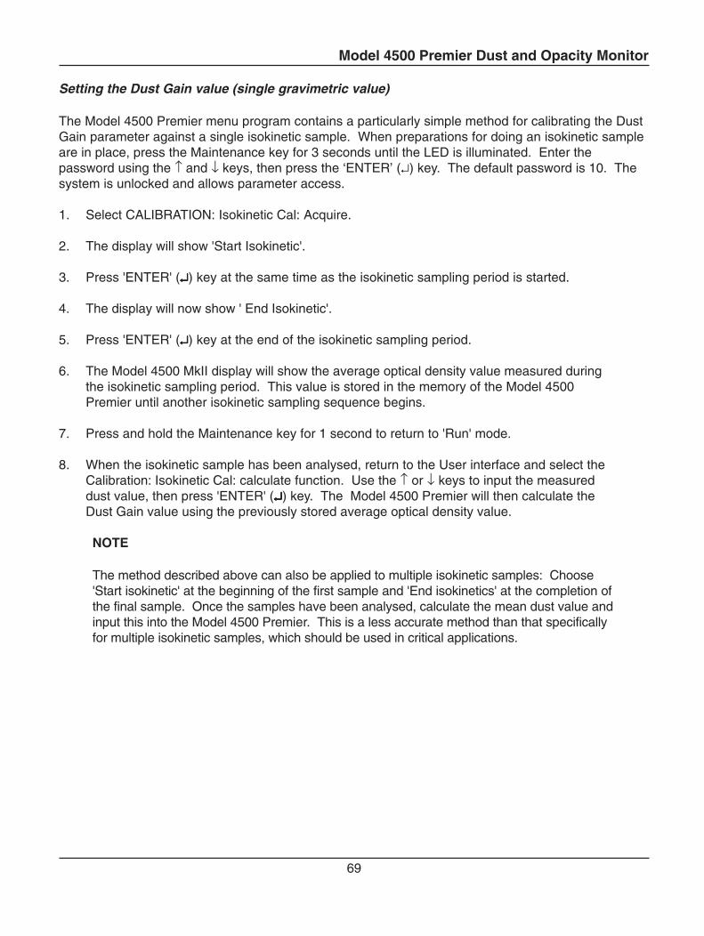
Model 4500 Premier Dust and Opacity Monitor
69
Setting the Dust Gain value (single gravimetric value)
The Model 4500 Premier menu program contains a particularly simple method for calibrating the DustGain parameter against a single isokinetic sample. When preparations for doing an isokinetic sampleare in place, press the Maintenance key for 3 seconds until the LED is illuminated. Enter thepassword using the ↑ and ↓ keys, then press the ‘ENTER’ (↵) key. The default password is 10. Thesystem is unlocked and allows parameter access.
1. Select CALIBRATION: Isokinetic Cal: Acquire.
2. The display will show 'Start Isokinetic'.
3. Press 'ENTER' (↵↵↵↵↵) key at the same time as the isokinetic sampling period is started.
4. The display will now show ' End Isokinetic'.
5. Press 'ENTER' (↵↵↵↵↵) key at the end of the isokinetic sampling period.
6. The Model 4500 MkII display will show the average optical density value measured duringthe isokinetic sampling period. This value is stored in the memory of the Model 4500Premier until another isokinetic sampling sequence begins.
7. Press and hold the Maintenance key for 1 second to return to 'Run' mode.
8. When the isokinetic sample has been analysed, return to the User interface and select theCalibration: Isokinetic Cal: calculate function. Use the ↑ or ↓ keys to input the measureddust value, then press 'ENTER' (↵↵↵↵↵) key. The Model 4500 Premier will then calculate theDust Gain value using the previously stored average optical density value.
NOTE
The method described above can also be applied to multiple isokinetic samples: Choose'Start isokinetic' at the beginning of the first sample and 'End isokinetics' at the completion ofthe final sample. Once the samples have been analysed, calculate the mean dust value andinput this into the Model 4500 Premier. This is a less accurate method than that specificallyfor multiple isokinetic samples, which should be used in critical applications.
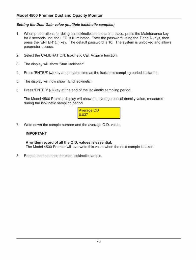
Model 4500 Premier Dust and Opacity Monitor
70
Average OD0.037
Setting the Dust Gain value (multiple isokinetic samples)
1. When preparations for doing an isokinetic sample are in place, press the Maintenance keyfor 3 seconds until the LED is illuminated. Enter the password using the ↑ and ↓ keys, thenpress the ‘ENTER’ (↵) key. The default password is 10. The system is unlocked and allowsparameter access.
2. Select the CALIBRATION: Isokinetic Cal: Acquire function.
3. The display will show 'Start Isokinetic'.
4. Press 'ENTER' (↵↵↵↵↵) key at the same time as the isokinetic sampling period is started.
5. The display will now show ' End Isokinetic'.
6. Press 'ENTER' (↵↵↵↵↵) key at the end of the isokinetic sampling period.
The Model 4500 Premier display will show the average optical density value, measuredduring the isokinetic sampling period.
7. Write down the sample number and the average O.D. value.
IMPORTANT
A written record of all the O.D. values is essential.The Model 4500 Premier will overwrite this value when the next sample is taken.
8. Repeat the sequence for each isokinetic sample.
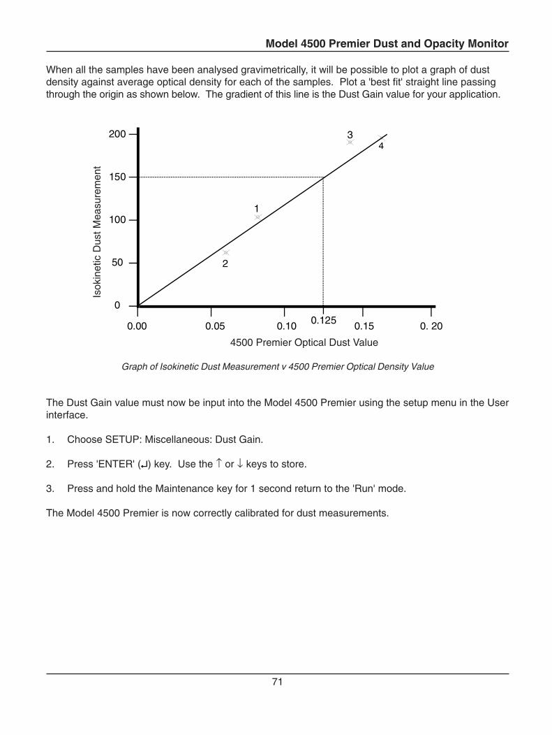
Model 4500 Premier Dust and Opacity Monitor
71
Isok
inet
ic D
ust M
easu
rem
ent
When all the samples have been analysed gravimetrically, it will be possible to plot a graph of dustdensity against average optical density for each of the samples. Plot a 'best fit' straight line passingthrough the origin as shown below. The gradient of this line is the Dust Gain value for your application.
1
2
3
200
150
100
50
0
0.05 0.10 0.15 0. 200.00 0.125
4500 Premier Optical Dust Value
Graph of Isokinetic Dust Measurement v 4500 Premier Optical Density Value
The Dust Gain value must now be input into the Model 4500 Premier using the setup menu in the Userinterface.
1. Choose SETUP: Miscellaneous: Dust Gain.
2. Press 'ENTER' (↵↵↵↵↵) key. Use the ↑ or ↓ keys to store.
3. Press and hold the Maintenance key for 1 second return to the 'Run' mode.
The Model 4500 Premier is now correctly calibrated for dust measurements.
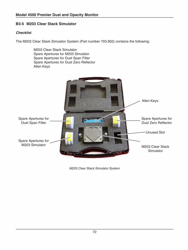
Model 4500 Premier Dust and Opacity Monitor
72
B3-5 M203 Clear Stack Simulator
Checklist
The M203 Clear Stack Simulator System (Part number 703.902) contains the following:
M203 Clear Stack SimulatorSpare Apertures for M203 SimulatorSpare Apertures for Dust Span FilterSpare Apertures for Dust Zero ReflectorAllen Keys
M203 Clear Stack Simulator System
Spare Apertures forDust Span Filter
Spare Apertures forM203 Simulator
Spare Apertures forDust Zero Reflector
Allen Keys
M203 Clear StackSimulator
Unused Slot

Model 4500 Premier Dust and Opacity Monitor
73
The instrument serial number and pathlength are printed on the carry case label. It is important thatthe M203 is only used with the instrument it has been calibrated with. Please ensure the plantinstallation location (i.e. Stack 1) is written on the carry case label before placing the clear sticky label(Provided by Land) over the top of the carry case label for protection.
M203 CLEAR STACK SIMULATORINST. SERIAL No
PATH LENGTH
INST. LOCATION
M203 Carry Case Label
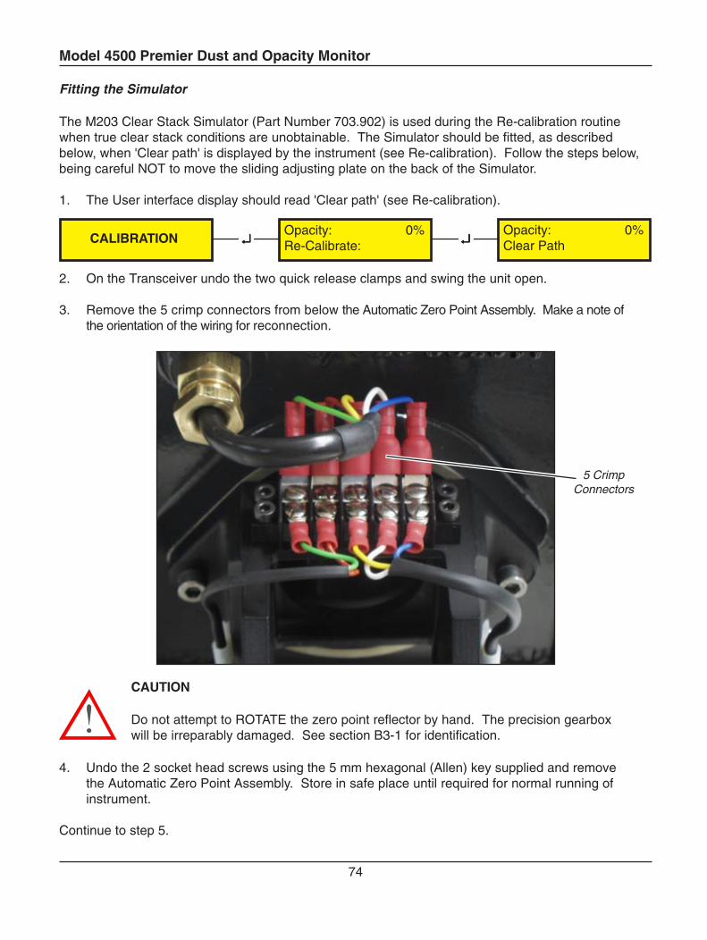
Model 4500 Premier Dust and Opacity Monitor
74
Fitting the Simulator
The M203 Clear Stack Simulator (Part Number 703.902) is used during the Re-calibration routinewhen true clear stack conditions are unobtainable. The Simulator should be fitted, as describedbelow, when 'Clear path' is displayed by the instrument (see Re-calibration). Follow the steps below,being careful NOT to move the sliding adjusting plate on the back of the Simulator.
1. The User interface display should read 'Clear path' (see Re-calibration).
2. On the Transceiver undo the two quick release clamps and swing the unit open.
3. Remove the 5 crimp connectors from below the Automatic Zero Point Assembly. Make a note ofthe orientation of the wiring for reconnection.
CAUTION
Do not attempt to ROTATE the zero point reflector by hand. The precision gearboxwill be irreparably damaged. See section B3-1 for identification.
4. Undo the 2 socket head screws using the 5 mm hexagonal (Allen) key supplied and removethe Automatic Zero Point Assembly. Store in safe place until required for normal running ofinstrument.
Continue to step 5.
Opacity: 0%Clear Path↵↵↵↵↵↵↵↵↵↵CALIBRATION
Opacity: 0%Re-Calibrate:
5 CrimpConnectors
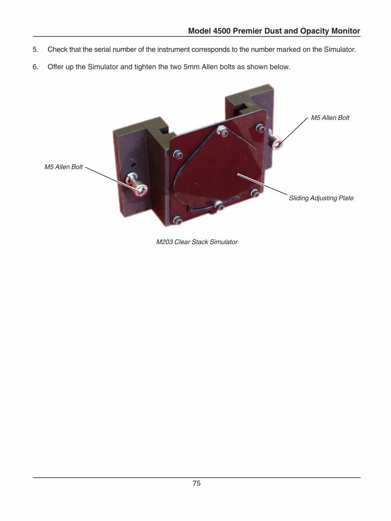
Model 4500 Premier Dust and Opacity Monitor
75
5. Check that the serial number of the instrument corresponds to the number marked on the Simulator.
6. Offer up the Simulator and tighten the two 5mm Allen bolts as shown below.
M203 Clear Stack Simulator
M5 Allen Bolt
Sliding Adjusting Plate
M5 Allen Bolt
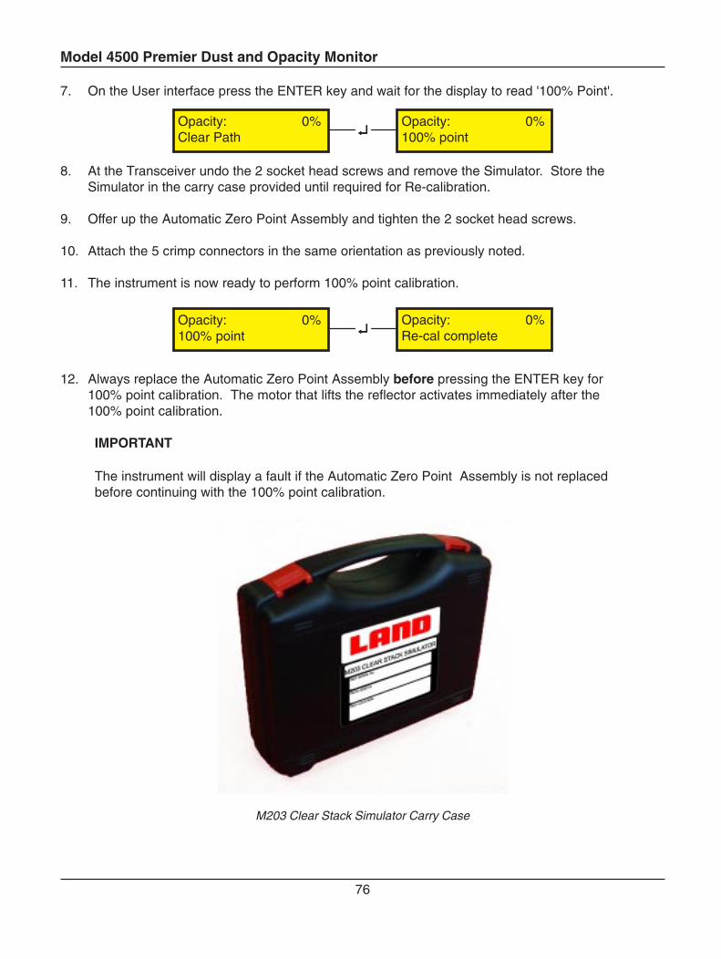
Model 4500 Premier Dust and Opacity Monitor
76
↵↵↵↵↵Opacity: 0%Clear Path
Opacity: 0%100% point
Opacity: 0%Re-cal complete↵↵↵↵↵Opacity: 0%
100% point
7. On the User interface press the ENTER key and wait for the display to read '100% Point'.
8. At the Transceiver undo the 2 socket head screws and remove the Simulator. Store theSimulator in the carry case provided until required for Re-calibration.
9. Offer up the Automatic Zero Point Assembly and tighten the 2 socket head screws.
10. Attach the 5 crimp connectors in the same orientation as previously noted.
11. The instrument is now ready to perform 100% point calibration.
12. Always replace the Automatic Zero Point Assembly before pressing the ENTER key for100% point calibration. The motor that lifts the reflector activates immediately after the100% point calibration.
IMPORTANT
The instrument will display a fault if the Automatic Zero Point Assembly is not replacedbefore continuing with the 100% point calibration.
M203 Clear Stack Simulator Carry Case
Model 4500 Premier Dust and Opacity Monitor
77
B3-6 M203 Clear Stack Simulator Calibration
All instruments are shipped out from the factory configured to customers' requirements. Re-calibrationof the M203 Clear Stack Simulator is required immediately after re-calibration of the instrument. It isrecommended that re-calibration is performed every three years or if a Calibration Audit shows theinstrument to be outside of acceptable limits. Please ensure that all optical surfaces are clean and theoptical path is not obstructed before performing any calibration.
If the flange to flange path length is altered (i.e. due to relocation of the instrument) contact Landcustomer services for instrument pathlength setup advice.
IMPORTANT
Re-calibration should be carried out under clear stack conditions or in a laboratory with theTransceiver set to the correct flange-to-flange path length.The M203 Clear Stack Simulator should be re-calibrated following a genuine re-calibration of the instrument only (recommended every three years).
If in any doubt about these instructions, please contact Land Customer Services Departmentbefore proceeding. Take care when handling the reflective surfaces as they can easily be scratchedor made dirty.
CAUTION
Do not attempt to ROTATE the zero point reflector by hand. The precision gearboxwill be irreparably damaged. See section B3-1 for identification.
Immediately after a genuine clear stack re-calibration perform the following steps for re-calibration ofthe M203 Clear Stack Simulator.
1. Press the Maintenance key for 3 seconds until the LED is illuminated. The system isunlocked and allows parameter access.
2. Enter the password using the ↑ and ↓ keys, then press the ‘ENTER’ (↵) key. The defaultpassword is 10.
3. Undo the two quick release clamps on the Transceiver, swing open the case and identify theAutomatic Zero Point Assembly
Continue to step 4.

Model 4500 Premier Dust and Opacity Monitor
78
Automatic Zero Point Assembly
4. Remove the Automatic Zero Point Assembly by undoing the two socket head screws.
5. Fit the M203 Clear Stack Simulator as described in the previous section.
6. At the User interface set the instrument to display negative values (see section C4-4) andthen observe the measurement reading with the M203 Clear Stack Simulator still attached.
7. Loosen the locking nut on the sliding adjusting plate and slide the plate until the instrument ismeasuring zero.
If the instrument cannot be set to measure zero opacity by adjusting the sliding adjuster on the back ofthe M203 Simulator it is necessary to change the aperture and grating that cover the reflective surface.
Select an aperture plate and grating using the table in Appendix A-1. Identify the ‘B’ valuecorresponding to the aperture plate and grating in use (i.e. Aperture Plate D, Grating 2 corresponding‘B’ value 0.94).
If the black wedge shape on the front of the sliding adjuster on the M203 Simulator completely coversthe reflective surface then replace the current aperture plate and grating with the ones correspondingto the next highest ‘B’ value (i.e. Next highest ‘B’ value 0.97 corresponding aperture plate C andgrating 2).
If the black wedge shape on the front of the sliding adjuster on the M203 Simulator cannot be seenthen replace the current aperture plate and grating with the ones corresponding to the next lowest ‘B’value (i.e. Next lowest ‘B’ value 0.91 corresponding aperture plate E and grating 2).
Continue to step 8.
Model 4500 Premier Dust and Opacity Monitor
79
8. Lock the sliding adjusting plate in place.
IMPORTANT
The M203 Clear Stack Simulator once calibrated to an instrument should not be adjustedunless undergoing another re-calibration.
9. Undo the 2 socket head screws and remove the Simulator. Store the Simulator in the carrycase provided until required for Re-calibration.
10. Offer up the Automatic Zero Point Assembly and tighten the 2 socket head screws.
11. Attach the 5 crimp connectors in the same orientation as previously noted.
12. Close the Transceiver casing and press the Maintenance key for 1 second until the LEDswitches off. The instrument is now in ‘RUN’ mode.
The instrument is now ready for normal operation.
Model 4500 Premier Dust and Opacity Monitor
80
B3-7 Zero Point Reflector Adjustment
All instruments are shipped out from the factory configured to customers' requirements.
The following procedures should only be necessary if the optical path length or theopacity standard has been changed. It is mandatory for installations complying withUSEPA regulations.
If in any doubt about these instructions, please contact Land Customer Services Department beforeproceeding. Take care when handling the reflective surfaces as they can easily be scratched or madedirty.
CAUTION
Do not attempt to ROTATE the zero point reflector by hand. The precision gearboxwill be irreparably damaged. See section B3-1 for identification.
1. Remove the instrument from the stack and set up on test stands positioned at the correctflange to flange distance.
2. Press the Maintenance key for 3 seconds until the LED is illuminated. The system is unlockedand allows parameter access.
3. Perform a Re-calibration (see section B3-3).
4. Display and make note of the 'B' value on the Parameters menu (see section B3-6).
5. On the table in Appendix A find the 'B' value (or the nearest lower value). The value may occurin two columns. Select the Aperture Plate (horizontally) and the Grating (vertically) relating tothe 'B' value.
6. Install the selected Aperture Plate and Grating as described in this section.
Continue to step 7.
Model 4500 Premier Dust and Opacity Monitor
81
7. Repeat the Re-calibration procedure (see section B3-3).
8. Display the parameter 'B' on the Parameters menu (see section B3-6).
9. The 'B' value should now be within the range 0.95 to 1.05. The zero point reflector is readyfor normal use. If the 'B' value is not within the range 0.95 to 1.05 then it will be necessaryto change the aperture and grating as described below.
If the 'B' value is less than 0.95 use the Aperture Plate belowthe previously selected aperture plate in the table.
If the 'B' value is greater than 1.05 use the Aperture Plate abovethe previously selected aperture plate in the table.
10. Repeat the Re-calibration as before and check the 'B' value again. Repeat steps 6 to 10 ifrequired.
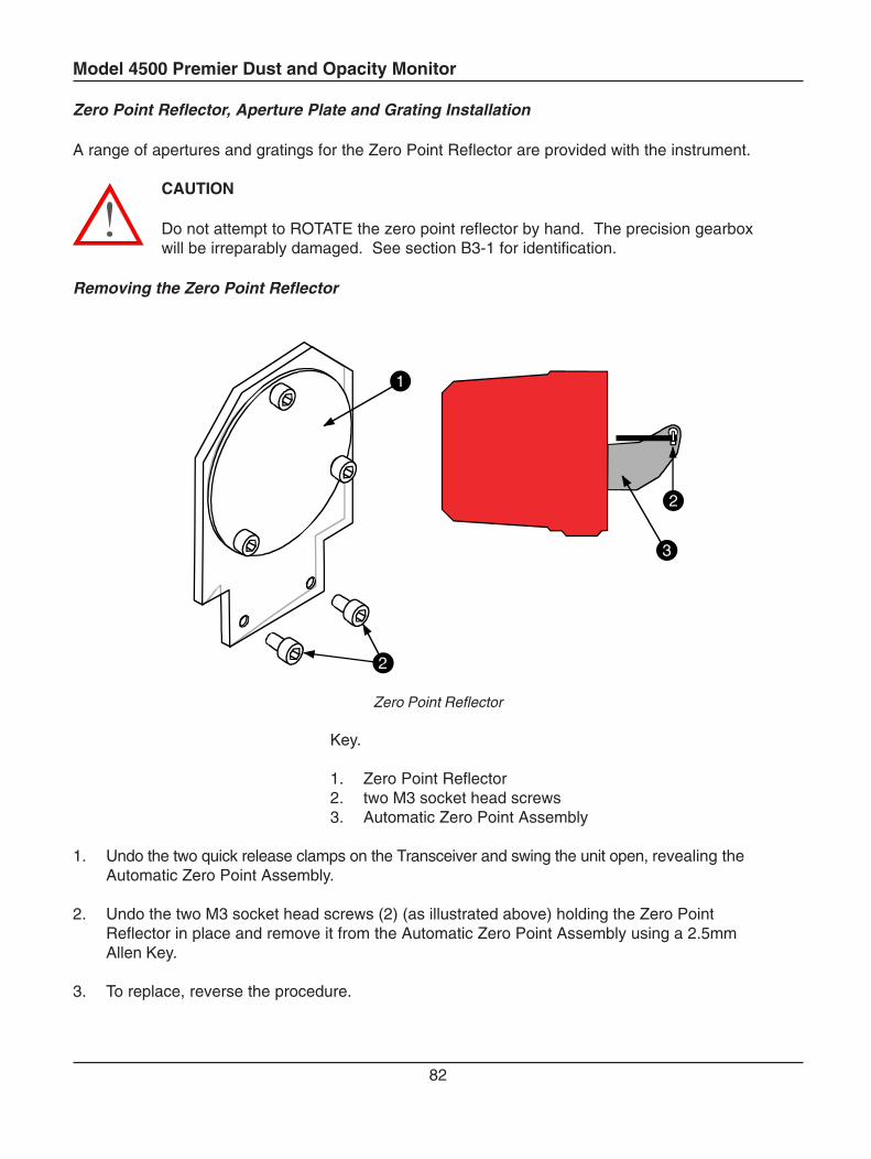
Model 4500 Premier Dust and Opacity Monitor
82
Zero Point Reflector, Aperture Plate and Grating Installation
A range of apertures and gratings for the Zero Point Reflector are provided with the instrument.
CAUTION
Do not attempt to ROTATE the zero point reflector by hand. The precision gearboxwill be irreparably damaged. See section B3-1 for identification.
Removing the Zero Point Reflector
1
2
2
3
Zero Point Reflector
Key.
1. Zero Point Reflector2. two M3 socket head screws3. Automatic Zero Point Assembly
1. Undo the two quick release clamps on the Transceiver and swing the unit open, revealing theAutomatic Zero Point Assembly.
2. Undo the two M3 socket head screws (2) (as illustrated above) holding the Zero PointReflector in place and remove it from the Automatic Zero Point Assembly using a 2.5mmAllen Key.
3. To replace, reverse the procedure.
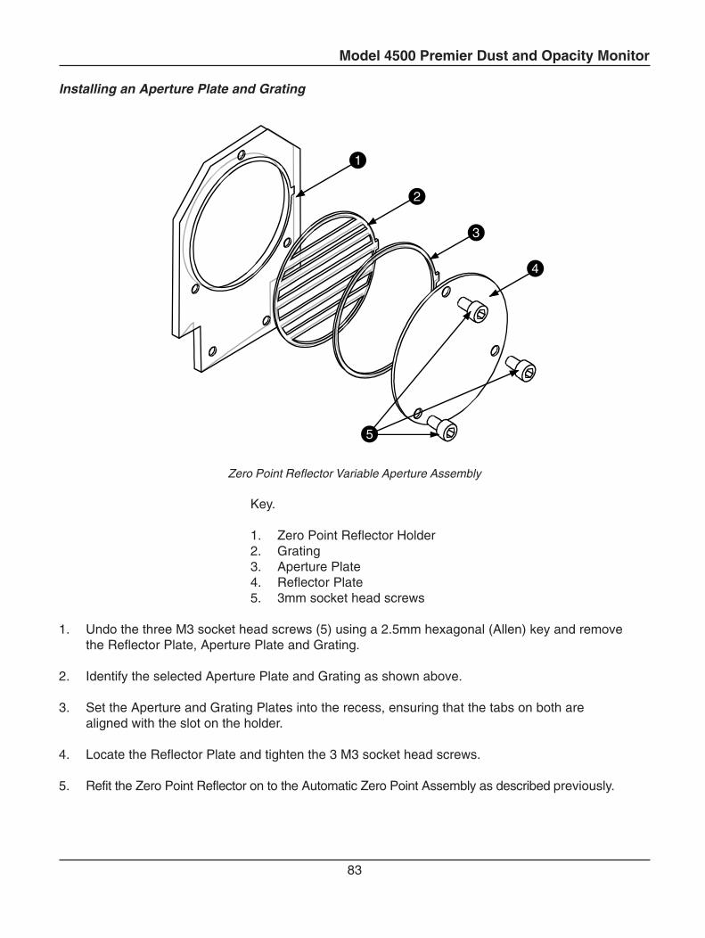
Model 4500 Premier Dust and Opacity Monitor
83
Installing an Aperture Plate and Grating
1
2
3
4
5
Zero Point Reflector Variable Aperture Assembly
Key.
1. Zero Point Reflector Holder2. Grating3. Aperture Plate4. Reflector Plate5. 3mm socket head screws
1. Undo the three M3 socket head screws (5) using a 2.5mm hexagonal (Allen) key and removethe Reflector Plate, Aperture Plate and Grating.
2. Identify the selected Aperture Plate and Grating as shown above.
3. Set the Aperture and Grating Plates into the recess, ensuring that the tabs on both arealigned with the slot on the holder.
4. Locate the Reflector Plate and tighten the 3 M3 socket head screws.
5. Refit the Zero Point Reflector on to the Automatic Zero Point Assembly as described previously.
Model 4500 Premier Dust and Opacity Monitor
84
B3-8 Upscale Span Filter Adjustment
U.S. Legislation requires that the instrument is periodically checked using an Upscale CalibrationValue that is 150% to 190% of the applicable opacity standard. This is achieved using an AutomaticSpan Filter. A range of gratings for the Span Filter are provided with nominal Opacities of 5%, 10%,15%, 20%, 28%, 36%, and 45%. The instrument is factory set with a span filter of 28%.
To install an alternative filter from the set provided, follow the procedure outlined below.
Removing the Span Filter
1. Ensure that the power to the instrument is switched off.
2. Undo the two quick release clamps on the Transceiver and swing the unit open, revealing theAutomatic Zero Point Assembly.
3. Undo the hinge pins (captive in the purge assembly) using a 5mm Allen key and lift theTransceiver away from the purge assembly.
4. Undo the sixteen M4 socket head screws holding the outer casing in place using a 3mmhexagonal (Allen) key and partly withdraw the casing.
NOTE
A Static protection wrist band should be worn at this point
5. Disconnect the Umbilical Klippon terminal strip and remove the outer casing.
Continue to step 6.
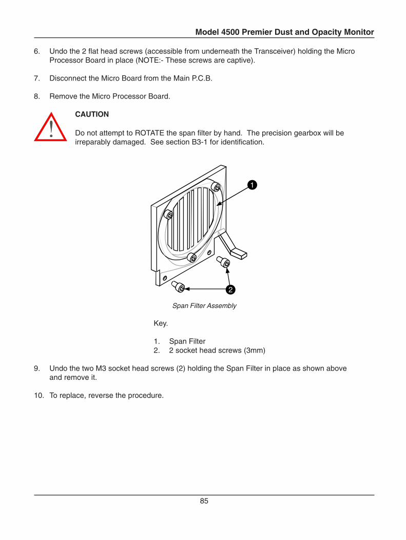
Model 4500 Premier Dust and Opacity Monitor
85
6. Undo the 2 flat head screws (accessible from underneath the Transceiver) holding the MicroProcessor Board in place (NOTE:- These screws are captive).
7. Disconnect the Micro Board from the Main P.C.B.
8. Remove the Micro Processor Board.
CAUTION
Do not attempt to ROTATE the span filter by hand. The precision gearbox will beirreparably damaged. See section B3-1 for identification.
1
2
Span Filter Assembly
Key.
1. Span Filter2. 2 socket head screws (3mm)
9. Undo the two M3 socket head screws (2) holding the Span Filter in place as shown aboveand remove it.
10. To replace, reverse the procedure.
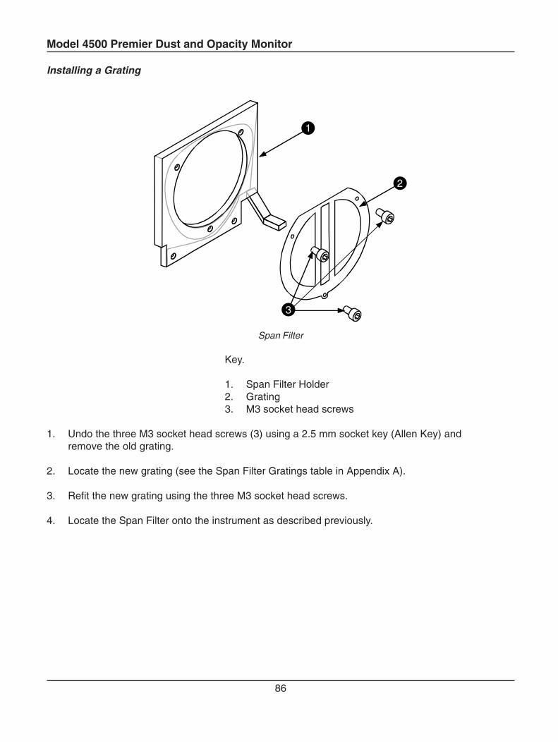
Model 4500 Premier Dust and Opacity Monitor
86
Installing a Grating
1
2
3
Span Filter
Key.
1. Span Filter Holder2. Grating3. M3 socket head screws
1. Undo the three M3 socket head screws (3) using a 2.5 mm socket key (Allen Key) andremove the old grating.
2. Locate the new grating (see the Span Filter Gratings table in Appendix A).
3. Refit the new grating using the three M3 socket head screws.
4. Locate the Span Filter onto the instrument as described previously.
Model 4500 Premier Dust and Opacity Monitor
87
C1 Theory of Operation and Application
C1-1 General Outline
When a beam of light crosses a medium containing smoke or dust particles, some of the light is transmittedand some is lost due to scattering. The fraction which is transmitted is called the transmittance andthe fraction which is lost is the opacity.
In the early days of emissions measurement, the opacity of the smoke leaving a stack was measured bythe Ringelmann method in which a trained observer makes a visual estimate of its appearance.
Modern methods for opacity measurement are far more sophisticated than the Ringelmann method, butmany of the specifications relate back to the way the human eye sees smoke emissions. The wavelengthresponse of an opacity monitor must mimic that of the human eye. An instrument must have a nearlyphotopic response. The Land Model 4500 Premier uses a high-intensity green LED light source to achievethis.
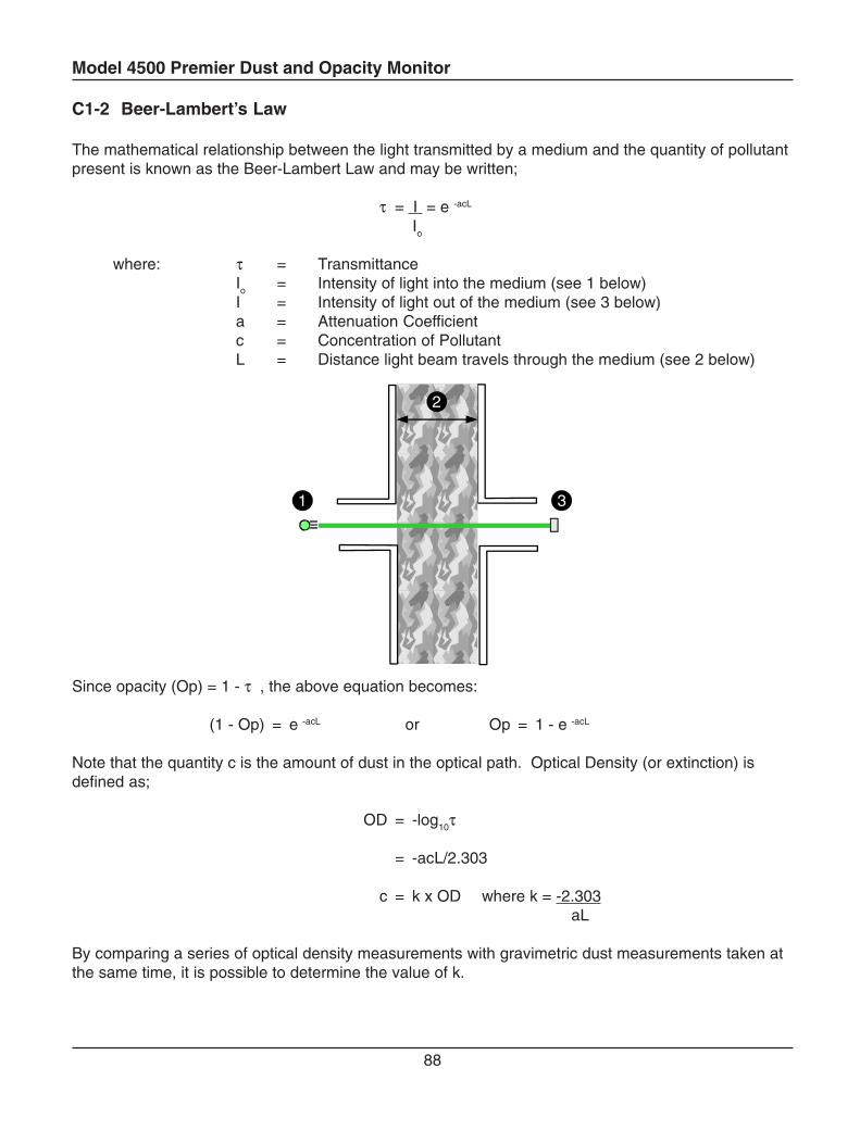
Model 4500 Premier Dust and Opacity Monitor
88
C1-2 Beer-Lambert’s Law
The mathematical relationship between the light transmitted by a medium and the quantity of pollutantpresent is known as the Beer-Lambert Law and may be written;
τ = I = e -acL
Io
where: τ = TransmittanceIo = Intensity of light into the medium (see 1 below)I = Intensity of light out of the medium (see 3 below)a = Attenuation Coefficientc = Concentration of PollutantL = Distance light beam travels through the medium (see 2 below)
1
2
3
Since opacity (Op) = 1 - τ , the above equation becomes:
(1 - Op) = e -acL or Op = 1 - e -acL
Note that the quantity c is the amount of dust in the optical path. Optical Density (or extinction) isdefined as;
OD = -log10τ
= -acL/2.303
c = k x OD where k = -2.303aL
By comparing a series of optical density measurements with gravimetric dust measurements taken atthe same time, it is possible to determine the value of k.
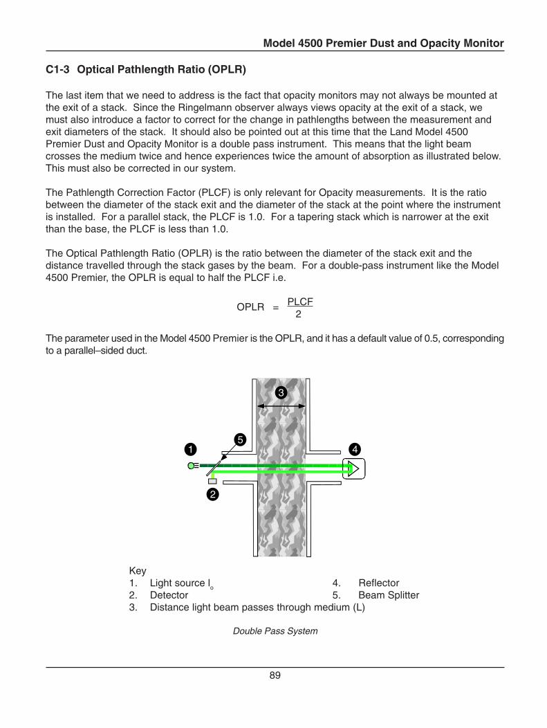
Model 4500 Premier Dust and Opacity Monitor
89
C1-3 Optical Pathlength Ratio (OPLR)
The last item that we need to address is the fact that opacity monitors may not always be mounted atthe exit of a stack. Since the Ringelmann observer always views opacity at the exit of a stack, wemust also introduce a factor to correct for the change in pathlengths between the measurement andexit diameters of the stack. It should also be pointed out at this time that the Land Model 4500Premier Dust and Opacity Monitor is a double pass instrument. This means that the light beamcrosses the medium twice and hence experiences twice the amount of absorption as illustrated below.This must also be corrected in our system.
The Pathlength Correction Factor (PLCF) is only relevant for Opacity measurements. It is the ratiobetween the diameter of the stack exit and the diameter of the stack at the point where the instrumentis installed. For a parallel stack, the PLCF is 1.0. For a tapering stack which is narrower at the exitthan the base, the PLCF is less than 1.0.
The Optical Pathlength Ratio (OPLR) is the ratio between the diameter of the stack exit and thedistance travelled through the stack gases by the beam. For a double-pass instrument like the Model4500 Premier, the OPLR is equal to half the PLCF i.e.
OPLR = PLCF2
The parameter used in the Model 4500 Premier is the OPLR, and it has a default value of 0.5, correspondingto a parallel–sided duct.
1
2
3
45
Key1. Light source lo 4. Reflector2. Detector 5. Beam Splitter3. Distance light beam passes through medium (L)
Double Pass System
Model 4500 Premier Dust and Opacity Monitor
90
We can use the previous equations to calculate the opacity at the stack exit, if we define the pathlengthcorrection factor (PLCF);
PLCF = Le
Lm
where: Le = the exit pathlengthLm = the measurement pathlength
OPLR = PLCF2
Ope = 1 - 10 -OD × OPLR
Note: The Model 4500 Premier applies the OPLR correction only to the measured opacity. Opticaldensity is shown as the double-pass value.
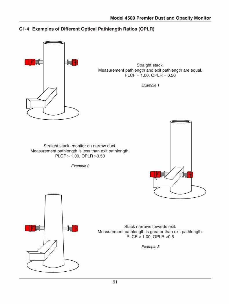
Model 4500 Premier Dust and Opacity Monitor
91
C1-4 Examples of Different Optical Pathlength Ratios (OPLR)
Straight stack.Measurement pathlength and exit pathlength are equal.
PLCF = 1.00, OPLR = 0.50
Example 1
Straight stack, monitor on narrow duct.Measurement pathlength is less than exit pathlength.
PLCF > 1.00, OPLR >0.50
Example 2
Stack narrows towards exit.Measurement pathlength is greater than exit pathlength.
PLCF < 1.00, OPLR <0.5
Example 3

Model 4500 Premier Dust and Opacity Monitor
92
C2 Requirements for Environmental Legislation
The Model 4500 Premier meets or exceeds the requirements of U.S. 40CR60 AppB PS1, CPS-0001and ASTM Standard Practice D6216.
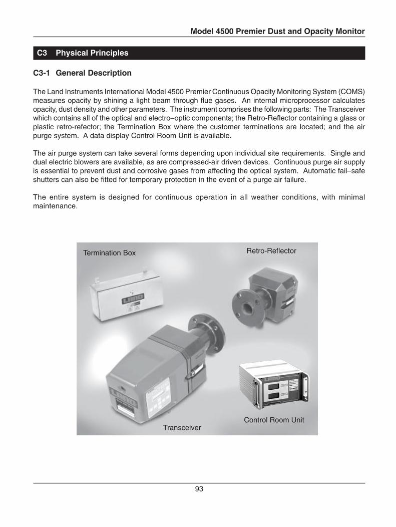
Model 4500 Premier Dust and Opacity Monitor
93
C3 Physical Principles
C3-1 General Description
The Land Instruments International Model 4500 Premier Continuous Opacity Monitoring System (COMS)measures opacity by shining a light beam through flue gases. An internal microprocessor calculatesopacity, dust density and other parameters. The instrument comprises the following parts: The Transceiverwhich contains all of the optical and electro–optic components; the Retro-Reflector containing a glass orplastic retro-refector; the Termination Box where the customer terminations are located; and the airpurge system. A data display Control Room Unit is available.
The air purge system can take several forms depending upon individual site requirements. Single anddual electric blowers are available, as are compressed-air driven devices. Continuous purge air supplyis essential to prevent dust and corrosive gases from affecting the optical system. Automatic fail–safeshutters can also be fitted for temporary protection in the event of a purge air failure.
The entire system is designed for continuous operation in all weather conditions, with minimalmaintenance.
Control Room Unit
Retro-ReflectorTermination Box
Transceiver
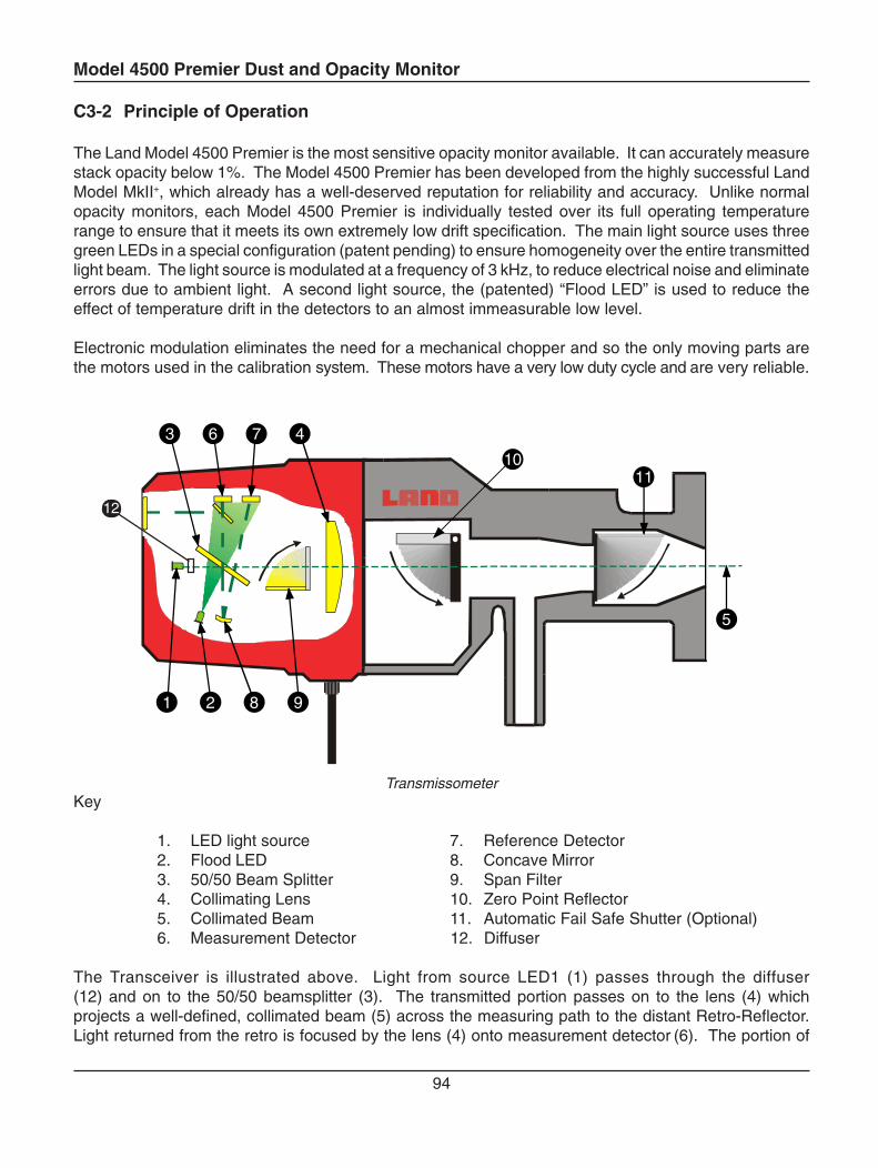
Model 4500 Premier Dust and Opacity Monitor
94
C3-2 Principle of Operation
The Land Model 4500 Premier is the most sensitive opacity monitor available. It can accurately measurestack opacity below 1%. The Model 4500 Premier has been developed from the highly successful LandModel MkII+, which already has a well-deserved reputation for reliability and accuracy. Unlike normalopacity monitors, each Model 4500 Premier is individually tested over its full operating temperaturerange to ensure that it meets its own extremely low drift specification. The main light source uses threegreen LEDs in a special configuration (patent pending) to ensure homogeneity over the entire transmittedlight beam. The light source is modulated at a frequency of 3 kHz, to reduce electrical noise and eliminateerrors due to ambient light. A second light source, the (patented) “Flood LED” is used to reduce theeffect of temperature drift in the detectors to an almost immeasurable low level.
Electronic modulation eliminates the need for a mechanical chopper and so the only moving parts arethe motors used in the calibration system. These motors have a very low duty cycle and are very reliable.
11
1 2 8 9
3 6 7 4
10
5
TransmissometerKey
1. LED light source 7. Reference Detector2. Flood LED 8. Concave Mirror3. 50/50 Beam Splitter 9. Span Filter4. Collimating Lens 10. Zero Point Reflector5. Collimated Beam 11. Automatic Fail Safe Shutter (Optional)6. Measurement Detector 12. Diffuser
The Transceiver is illustrated above. Light from source LED1 (1) passes through the diffuser(12) and on to the 50/50 beamsplitter (3). The transmitted portion passes on to the lens (4) whichprojects a well-defined, collimated beam (5) across the measuring path to the distant Retro-Reflector.Light returned from the retro is focused by the lens (4) onto measurement detector
(6). The portion of
12
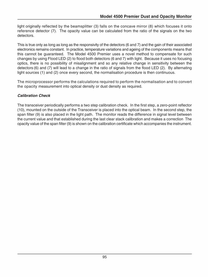
Model 4500 Premier Dust and Opacity Monitor
95
light originally reflected by the beamsplitter (3) falls on the concave mirror (8) which focuses it ontoreference detector (7). The opacity value can be calculated from the ratio of the signals on the twodetectors.
This is true only as long as long as the responsivity of the detectors (6 and 7) and the gain of their associatedelectronics remains constant. In practice, temperature variations and ageing of the components means thatthis cannot be guaranteed. The Model 4500 Premier uses a novel method to compensate for suchchanges by using Flood LED (2) to flood both detectors (6 and 7) with light. Because it uses no focusingoptics, there is no possibility of misalignment and so any relative change in sensitivity between thedetectors (6) and (7) will lead to a change in the ratio of signals from the flood LED (2). By alternatinglight sources (1) and (2) once every second, the normalisation procedure is then continuous.
The microprocessor performs the calculations required to perform the normalisation and to convertthe opacity measurement into optical density or dust density as required.
Calibration Check
The transceiver periodically performs a two step calibration check. In the first step, a zero-point reflector(10), mounted on the outside of the Transceiver is placed into the optical beam. In the second step, thespan filter (9) is also placed in the light path. The monitor reads the difference in signal level betweenthe current value and that established during the last clear stack calibration and makes a correction Theopacity value of the span filter (9) is shown on the calibration certificate which accompanies the instrument.
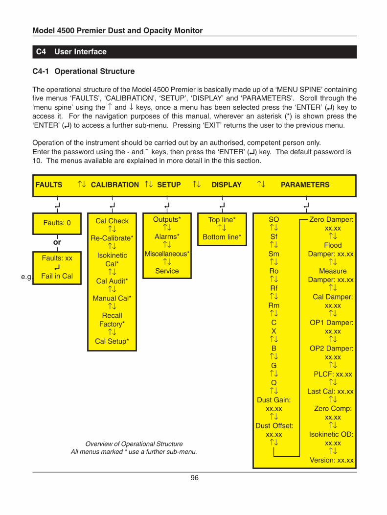
Model 4500 Premier Dust and Opacity Monitor
96
C4 User Interface
C4-1 Operational Structure
The operational structure of the Model 4500 Premier is basically made up of a ‘MENU SPINE’ containingfive menus ‘FAULTS’, ‘CALIBRATION’, ‘SETUP’, ‘DISPLAY’ and ‘PARAMETERS’. Scroll through the‘menu spine’ using the ↑ and ↓ keys, once a menu has been selected press the ‘ENTER’ (↵↵↵↵↵) key toaccess it. For the navigation purposes of this manual, wherever an asterisk (*) is shown press the‘ENTER’ (↵↵↵↵↵) to access a further sub-menu. Pressing ‘EXIT’ returns the user to the previous menu.
Operation of the instrument should be carried out by an authorised, competent person only.Enter the password using the - and ¯ keys, then press the ‘ENTER’ (↵↵↵↵↵) key. The default password is10. The menus available are explained in more detail in the this section.
Overview of Operational StructureAll menus marked * use a further sub-menu.
↵↵↵↵↵ ↵↵↵↵↵ ↵↵↵↵↵ ↵↵↵↵↵ ↵↵↵↵↵
or
FAULTS ↑↓ CALIBRATION ↑↓ SETUP ↑↓ DISPLAY ↑↓ PARAMETERS
Cal Check↑↓
Re-Calibrate*↑↓
IsokineticCal*↑↓
Cal Audit*↑↓
Manual Cal*↑↓
RecallFactory*
↑↓Cal Setup*
Outputs*↑↓
Alarms*↑↓
Miscellaneous*↑↓
Service
Top line*↑↓
Bottom line*
Faults: xx↵↵↵↵↵
Fail in Cal
Faults: 0 SO Zero Damper:↑↓ xx.xxSf ↑↓↑↓ FloodSm Damper: xx.xx↑↓ ↑↓Ro Measure↑↓ Damper: xx.xxRf ↑↓↑↓ Cal Damper:Rm xx.xx↑↓ ↑↓C OP1 Damper:X xx.xx
↑↓ ↑↓B OP2 Damper:
↑↓ xx.xxG ↑↓↑↓ PLCF: xx.xxQ ↑↓↑↓ Last Cal: xx.xx
Dust Gain: ↑↓xx.xx Zero Comp:
↑↓ xx.xxDust Offset: ↑↓
xx.xx Isokinetic OD:↑↓ xx.xx
↑↓Version: xx.xx
e.g.
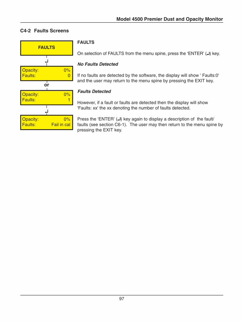
Model 4500 Premier Dust and Opacity Monitor
97
↵↵↵↵↵
↵↵↵↵↵
or
Opacity: 0%Faults: 0
Opacity: 0%Faults: 1
Opacity: 0%Faults: Fail in cal
FAULTS
C4-2 Faults Screens
FAULTS
On selection of FAULTS from the menu spine, press the ‘ENTER’ (↵↵↵↵↵) key.
No Faults Detected
If no faults are detected by the software, the display will show ' Faults:0'and the user may return to the menu spine by pressing the EXIT key.
Faults Detected
However, if a fault or faults are detected then the display will show'Faults: xx' the xx denoting the number of faults detected.
Press the ‘ENTER’ (↵↵↵↵↵) key again to display a description of the fault/faults (see section C6-1). The user may then return to the menu spine bypressing the EXIT key.
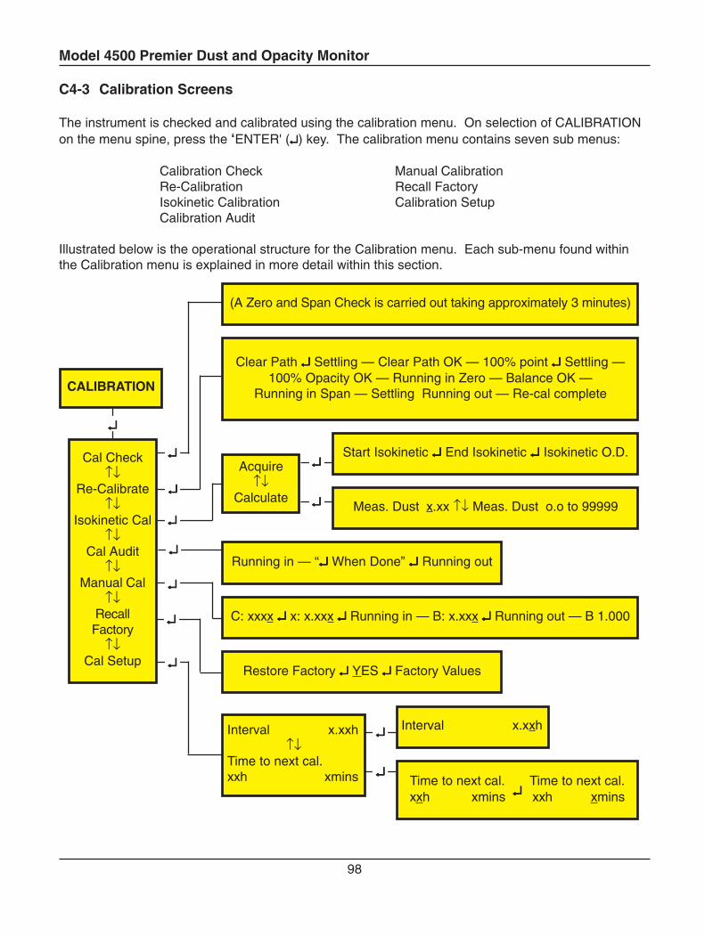
Model 4500 Premier Dust and Opacity Monitor
98
C4-3 Calibration Screens
The instrument is checked and calibrated using the calibration menu. On selection of CALIBRATIONon the menu spine, press the ‘ENTER' (↵↵↵↵↵) key. The calibration menu contains seven sub menus:
Calibration Check Manual CalibrationRe-Calibration Recall FactoryIsokinetic Calibration Calibration SetupCalibration Audit
Illustrated below is the operational structure for the Calibration menu. Each sub-menu found withinthe Calibration menu is explained in more detail within this section.
↵↵↵↵↵
↵↵↵↵↵
↵↵↵↵↵
↵↵↵↵↵
↵↵↵↵↵
↵↵↵↵↵
↵↵↵↵↵
↵↵↵↵↵
↵↵↵↵↵
↵↵↵↵↵
↵↵↵↵↵
↵↵↵↵↵
Clear Path ↵↵↵↵↵ Settling — Clear Path OK — 100% point ↵↵↵↵↵ Settling —100% Opacity OK — Running in Zero — Balance OK —
Running in Span — Settling Running out — Re-cal complete
Acquire↑↓
Calculate
Start Isokinetic ↵↵↵↵↵ End Isokinetic ↵↵↵↵↵ Isokinetic O.D.
Meas. Dust x.xx ↑↓ Meas. Dust o.o to 99999
Running in — “↵↵↵↵↵ When Done” ↵↵↵↵↵ Running out
C: xxxx ↵↵↵↵↵ x: x.xxx ↵↵↵↵↵ Running in — B: x.xxx ↵↵↵↵↵ Running out — B 1.000
Restore Factory ↵↵↵↵↵ YES ↵↵↵↵↵ Factory Values
Interval x.xxh↑↓
Time to next cal.xxh xmins
Interval x.xxh
Time to next cal. ↵↵↵↵↵
Time to next cal.xxh xmins xxh xmins
Cal Check↑↓
Re-Calibrate↑↓
Isokinetic Cal↑↓
Cal Audit↑↓
Manual Cal↑↓
RecallFactory
↑↓Cal Setup
(A Zero and Span Check is carried out taking approximately 3 minutes)
CALIBRATION
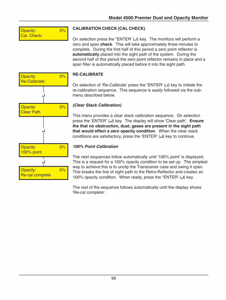
Model 4500 Premier Dust and Opacity Monitor
99
CALIBRATION CHECK (CAL CHECK)
On selection press the ‘ENTER' (↵↵↵↵↵) key. The monitors will perform azero and span check. This will take approximately three minutes tocomplete. During the first half of this period a zero point reflector isautomatically placed into the sight path of the system. During thesecond half of this period the zero point reflector remains in place and aspan filter is automatically placed before it into the sight path.
RE-CALIBRATE
On selection of ‘Re-Calibrate’ press the ‘ENTER' (↵↵↵↵↵) key to initiate there-calibration sequence. This sequence is easily followed via the sub-menu described below.
(Clear Stack Calibration)
This menu provides a clear stack calibration sequence. On selectionpress the ‘ENTER’ (↵↵↵↵↵) key. The display will show 'Clear path'. Ensurethe that no obstruction, dust, gases are present in the sight paththat would effect a zero opacity condition. When the clear stackconditions are satisfactory, press the ‘ENTER’ (↵↵↵↵↵) key to continue.
100% Point Calibration
The next sequences follow automatically until '100% point' is displayed.This is a request for a 100% opacity condition to be set up. The simplestway to achieve this is to unclip the Transceiver case and swing it open.This breaks the line of sight path to the Retro-Reflector and creates an100% opacity condition. When ready, press the ‘ENTER' (↵↵↵↵↵) key.
The rest of the sequence follows automatically until the display shows'Re-cal complete'.
↵↵↵↵↵
↵↵↵↵↵
↵↵↵↵↵
Opacity: 0%Cal. Check:
Opacity: 0%Re-Calibrate:
Opacity: 0%Clear Path
Opacity: 0%100% point
Opacity: 0%Re-cal complete
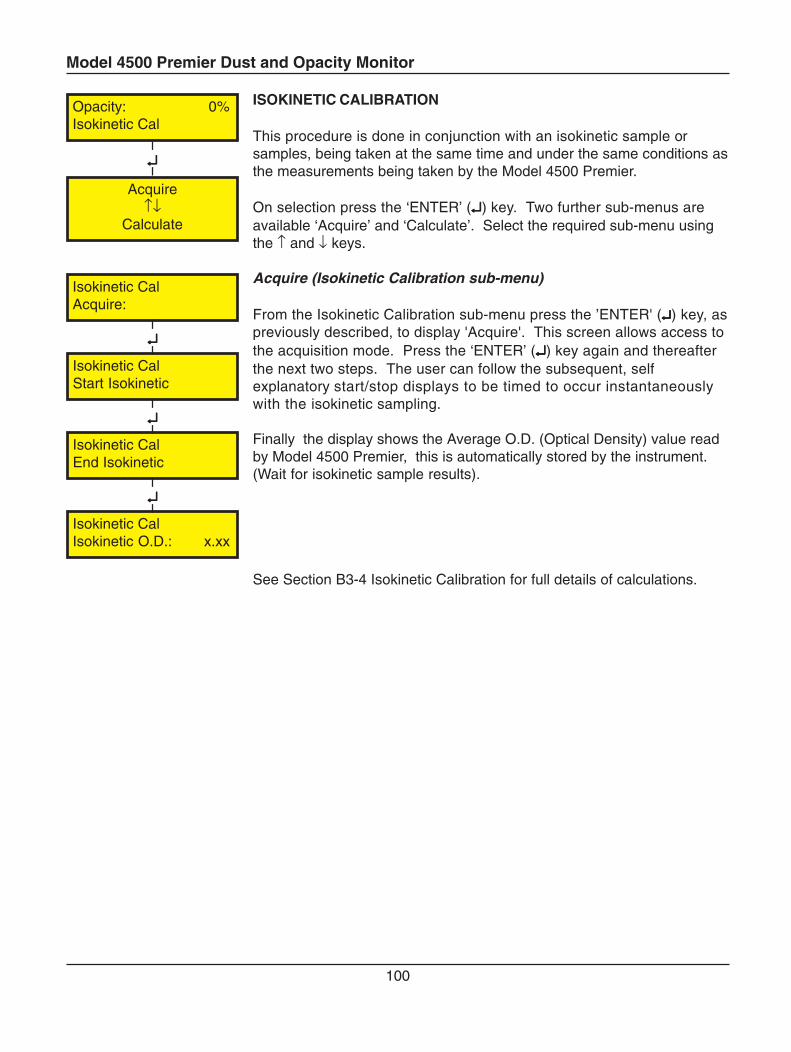
Model 4500 Premier Dust and Opacity Monitor
100
↵↵↵↵↵
↵↵↵↵↵
↵↵↵↵↵
Isokinetic CalAcquire:
Isokinetic CalIsokinetic O.D.: x.xx
Isokinetic CalEnd Isokinetic
Isokinetic CalStart Isokinetic
↵↵↵↵↵
Opacity: 0%Isokinetic Cal
Acquire↑↓
Calculate
ISOKINETIC CALIBRATION
This procedure is done in conjunction with an isokinetic sample orsamples, being taken at the same time and under the same conditions asthe measurements being taken by the Model 4500 Premier.
On selection press the ‘ENTER’ (↵↵↵↵↵) key. Two further sub-menus areavailable ‘Acquire’ and ‘Calculate’. Select the required sub-menu usingthe ↑ and ↓ keys.
Acquire (Isokinetic Calibration sub-menu)
From the Isokinetic Calibration sub-menu press the ’ENTER' (↵↵↵↵↵) key, aspreviously described, to display 'Acquire'. This screen allows access tothe acquisition mode. Press the ‘ENTER’ (↵↵↵↵↵) key again and thereafterthe next two steps. The user can follow the subsequent, selfexplanatory start/stop displays to be timed to occur instantaneouslywith the isokinetic sampling.
Finally the display shows the Average O.D. (Optical Density) value readby Model 4500 Premier, this is automatically stored by the instrument.(Wait for isokinetic sample results).
See Section B3-4 Isokinetic Calibration for full details of calculations.
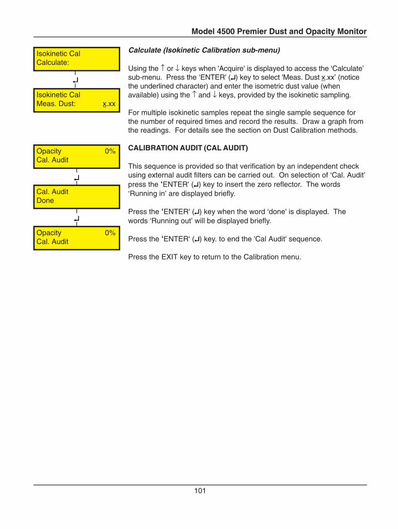
Model 4500 Premier Dust and Opacity Monitor
101
Calculate (Isokinetic Calibration sub-menu)
Using the ↑ or ↓ keys when 'Acquire' is displayed to access the ‘Calculate’sub-menu. Press the ‘ENTER' (↵↵↵↵↵) key to select 'Meas. Dust x.xx’ (noticethe underlined character) and enter the isometric dust value (whenavailable) using the ↑ and ↓ keys, provided by the isokinetic sampling.
For multiple isokinetic samples repeat the single sample sequence forthe number of required times and record the results. Draw a graph fromthe readings. For details see the section on Dust Calibration methods.
CALIBRATION AUDIT (CAL AUDIT)
This sequence is provided so that verification by an independent checkusing external audit filters can be carried out. On selection of ‘Cal. Audit’press the ‘ENTER' (↵↵↵↵↵) key to insert the zero reflector. The words‘Running in’ are displayed briefly.
Press the ‘ENTER' (↵↵↵↵↵) key when the word ‘done' is displayed. Thewords ‘Running out’ will be displayed briefly.
Press the ‘ENTER' (↵↵↵↵↵) key. to end the 'Cal Audit' sequence.
Press the EXIT key to return to the Calibration menu.
↵↵↵↵↵
↵↵↵↵↵
↵↵↵↵↵
Isokinetic CalCalculate:
Isokinetic CalMeas. Dust: x.xx
Opacity 0%Cal. Audit
Cal. AuditDone
Opacity 0%Cal. Audit
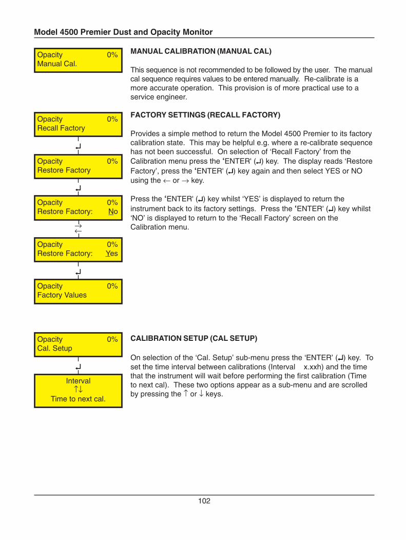
Model 4500 Premier Dust and Opacity Monitor
102
MANUAL CALIBRATION (MANUAL CAL)
This sequence is not recommended to be followed by the user. The manualcal sequence requires values to be entered manually. Re-calibrate is amore accurate operation. This provision is of more practical use to aservice engineer.
FACTORY SETTINGS (RECALL FACTORY)
Provides a simple method to return the Model 4500 Premier to its factorycalibration state. This may be helpful e.g. where a re-calibrate sequencehas not been successful. On selection of ‘Recall Factory’ from theCalibration menu press the ‘ENTER' (↵↵↵↵↵) key. The display reads ‘RestoreFactory’, press the ‘ENTER' (↵↵↵↵↵) key again and then select YES or NOusing the ← or → key.
Press the ‘ENTER' (↵↵↵↵↵) key whilst ‘YES’ is displayed to return theinstrument back to its factory settings. Press the ‘ENTER' (↵↵↵↵↵) key whilst‘NO’ is displayed to return to the ‘Recall Factory’ screen on theCalibration menu.
CALIBRATION SETUP (CAL SETUP)
On selection of the ‘Cal. Setup’ sub-menu press the ‘ENTER’ (↵↵↵↵↵) key. Toset the time interval between calibrations (Interval x.xxh) and the timethat the instrument will wait before performing the first calibration (Timeto next cal). These two options appear as a sub-menu and are scrolledby pressing the ↑ or ↓ keys.
↵↵↵↵↵
↵↵↵↵↵
↵↵↵↵↵
→←
↵↵↵↵↵
Opacity 0%Manual Cal.
Opacity 0%Restore Factory: Yes
Opacity 0%Restore Factory: No
Opacity 0%Restore Factory
Opacity 0%Recall Factory
Opacity 0%Factory Values
Opacity 0%Cal. Setup
Interval↑↓
Time to next cal.
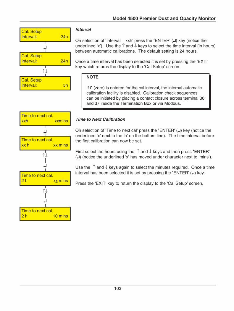
Model 4500 Premier Dust and Opacity Monitor
103
Interval
On selection of ‘Interval xxh’ press the ‘ENTER' (↵↵↵↵↵) key (notice theunderlined ‘x’). Use the ↑ and ↓ keys to select the time interval (in hours)between automatic calibrations. The default setting is 24 hours.
Once a time interval has been selected it is set by pressing the ‘EXIT’key which returns the display to the ‘Cal Setup’ screen.
NOTE
If 0 (zero) is entered for the cal interval, the internal automaticcalibration facility is disabled. Calibration check sequencescan be initiated by placing a contact closure across terminal 36and 37 inside the Termination Box or via Modbus.
Time to Next Calibration
On selection of ‘Time to next cal’ press the ‘ENTER' (↵↵↵↵↵) key (notice theunderlined ‘x’ next to the ‘h’ on the bottom line). The time interval beforethe first calibration can now be set.
First select the hours using the ↑ and ↓ keys and then press ‘ENTER'(↵↵↵↵↵) (notice the underlined ‘x’ has moved under character next to ‘mins’).
Use the ↑ and ↓ keys again to select the minutes required. Once a timeinterval has been selected it is set by pressing the ‘ENTER' (↵↵↵↵↵) key.
Press the ‘EXIT’ key to return the display to the ‘Cal Setup’ screen.
↵↵↵↵↵
↑↓
↵↵↵↵↵
↵↵↵↵↵
↑↓
↵↵↵↵↵
↑↓
Time to next cal.xxh xxmins
Cal. SetupInterval: 24h
Cal. SetupInterval: 24h
Cal. SetupInterval: 5h
Time to next cal.xx h xx mins
Time to next cal.2 h xx mins
Time to next cal.2 h 10 mins
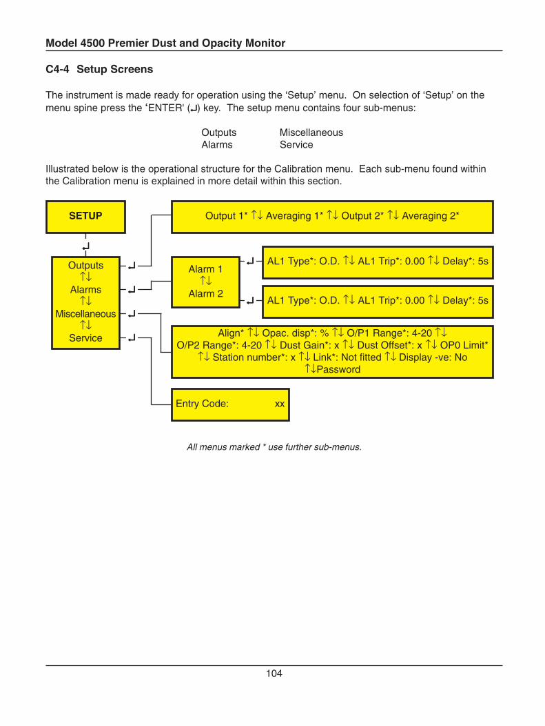
Model 4500 Premier Dust and Opacity Monitor
104
C4-4 Setup Screens
The instrument is made ready for operation using the ‘Setup’ menu. On selection of ‘Setup’ on themenu spine press the ‘ENTER' (↵↵↵↵↵) key. The setup menu contains four sub-menus:
Outputs MiscellaneousAlarms Service
Illustrated below is the operational structure for the Calibration menu. Each sub-menu found withinthe Calibration menu is explained in more detail within this section.
All menus marked * use further sub-menus.
↵↵↵↵↵
↵↵↵↵↵
↵↵↵↵↵
↵↵↵↵↵
↵↵↵↵↵
↵↵↵↵↵
↵↵↵↵↵
SETUP
Outputs↑↓
Alarms↑↓
Miscellaneous↑↓
Service
Output 1* ↑↓ Averaging 1* ↑↓ Output 2* ↑↓ Averaging 2*
Alarm 1↑↓
Alarm 2
AL1 Type*: O.D. ↑↓ AL1 Trip*: 0.00 ↑↓ Delay*: 5s
AL1 Type*: O.D. ↑↓ AL1 Trip*: 0.00 ↑↓ Delay*: 5s
Align* ↑↓ Opac. disp*: % ↑↓ O/P1 Range*: 4-20 ↑↓O/P2 Range*: 4-20 ↑↓ Dust Gain*: x ↑↓ Dust Offset*: x ↑↓ OP0 Limit*
↑↓ Station number*: x ↑↓ Link*: Not fitted ↑↓ Display -ve: No↑↓Password
Entry Code: xx
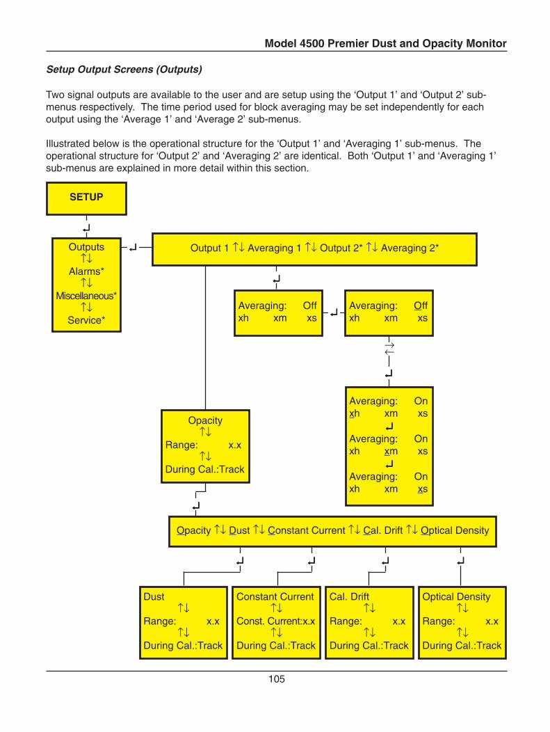
Model 4500 Premier Dust and Opacity Monitor
105
Setup Output Screens (Outputs)
Two signal outputs are available to the user and are setup using the ‘Output 1’ and ‘Output 2’ sub-menus respectively. The time period used for block averaging may be set independently for eachoutput using the ‘Average 1’ and ‘Average 2’ sub-menus.
Illustrated below is the operational structure for the ‘Output 1’ and ‘Averaging 1’ sub-menus. Theoperational structure for ‘Output 2’ and ‘Averaging 2’ are identical. Both ‘Output 1’ and ‘Averaging 1’sub-menus are explained in more detail within this section.
↵↵↵↵↵
↵↵↵↵↵
↵↵↵↵↵
↵↵↵↵↵
↵↵↵↵↵
→←
↵↵↵↵↵ ↵↵↵↵↵ ↵↵↵↵↵↵↵↵↵↵
↵↵↵↵↵
SETUP
Outputs↑↓
Alarms*↑↓
Miscellaneous*↑↓
Service*
Output 1 ↑↓ Averaging 1 ↑↓ Output 2* ↑↓ Averaging 2*
Averaging: Offxh xm xs
Averaging: Offxh xm xs
Averaging: Onxh xm xs
↵↵↵↵↵Averaging: Onxh xm xs
↵↵↵↵↵Averaging: Onxh xm xs
Dust↑↓
Range: x.x↑↓
During Cal.:Track
Cal. Drift↑↓
Range: x.x↑↓
During Cal.:Track
Optical Density↑↓
Range: x.x↑↓
During Cal.:Track
Constant Current↑↓
Const. Current:x.x↑↓
During Cal.:Track
Opacity ↑↓ Dust ↑↓ Constant Current ↑↓ Cal. Drift ↑↓ Optical Density
Opacity↑↓
Range: x.x↑↓
During Cal.:Track
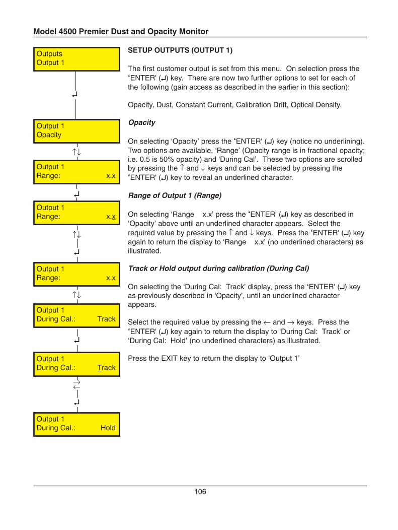
Model 4500 Premier Dust and Opacity Monitor
106
SETUP OUTPUTS (OUTPUT 1)
The first customer output is set from this menu. On selection press the‘ENTER' (↵↵↵↵↵) key. There are now two further options to set for each ofthe following (gain access as described in the earlier in this section):
Opacity, Dust, Constant Current, Calibration Drift, Optical Density.
Opacity
On selecting ‘Opacity’ press the ‘ENTER' (↵↵↵↵↵) key (notice no underlining).Two options are available, ‘Range’ (Opacity range is in fractional opacity;i.e. 0.5 is 50% opacity) and ‘During Cal’. These two options are scrolledby pressing the ↑ and ↓ keys and can be selected by pressing the‘ENTER' (↵↵↵↵↵) key to reveal an underlined character.
Range of Output 1 (Range)
On selecting ‘Range x.x’ press the ‘ENTER' (↵↵↵↵↵) key as described in‘Opacity’ above until an underlined character appears. Select therequired value by pressing the ↑ and ↓ keys. Press the ‘ENTER' (↵↵↵↵↵) keyagain to return the display to ‘Range x.x’ (no underlined characters) asillustrated.
Track or Hold output during calibration (During Cal)
On selecting the ‘During Cal: Track’ display, press the ‘ENTER' (↵↵↵↵↵) keyas previously described in ‘Opacity’, until an underlined characterappears.
Select the required value by pressing the ← and → keys. Press the‘ENTER' (↵↵↵↵↵) key again to return the display to ‘During Cal: Track’ or‘During Cal: Hold’ (no underlined characters) as illustrated.
Press the EXIT key to return the display to ‘Output 1’
↵↵↵↵↵
↵↵↵↵↵
↑↓
↵↵↵↵↵
→←
↵↵↵↵↵
↑↓
↑↓
↵↵↵↵↵
Output 1During Cal.: Hold
Output 1Opacity
Output 1Range: x.x
Output 1Range: x.x
Output 1During Cal.: Track
Output 1During Cal.: Track
Output 1Range: x.x
OutputsOutput 1
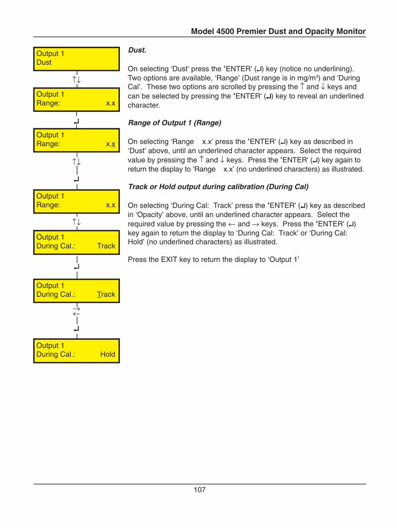
Model 4500 Premier Dust and Opacity Monitor
107
Dust.
On selecting ‘Dust’ press the ‘ENTER' (↵↵↵↵↵) key (notice no underlining).Two options are available, ‘Range’ (Dust range is in mg/m3) and ‘DuringCal’. These two options are scrolled by pressing the ↑ and ↓ keys andcan be selected by pressing the ‘ENTER' (↵↵↵↵↵) key to reveal an underlinedcharacter.
Range of Output 1 (Range)
On selecting ‘Range x.x’ press the ‘ENTER' (↵↵↵↵↵) key as described in‘Dust’ above, until an underlined character appears. Select the requiredvalue by pressing the ↑ and ↓ keys. Press the ‘ENTER' (↵↵↵↵↵) key again toreturn the display to ‘Range x.x’ (no underlined characters) as illustrated.
Track or Hold output during calibration (During Cal)
On selecting ‘During Cal: Track’ press the ‘ENTER' (↵↵↵↵↵) key as describedin ‘Opacity’ above, until an underlined character appears. Select therequired value by pressing the ← and → keys. Press the ‘ENTER' (↵↵↵↵↵)key again to return the display to ‘During Cal: Track’ or ‘During Cal:Hold’ (no underlined characters) as illustrated.
Press the EXIT key to return the display to ‘Output 1’
↵↵↵↵↵
↵↵↵↵↵
↑↓
↵↵↵↵↵
→←
↵↵↵↵↵
↑↓
↑↓
Output 1Dust
Output 1Range: x.x
Output 1Range: x.x
Output 1During Cal.: Track
Output 1During Cal.: Track
Output 1Range: x.x
Output 1During Cal.: Hold
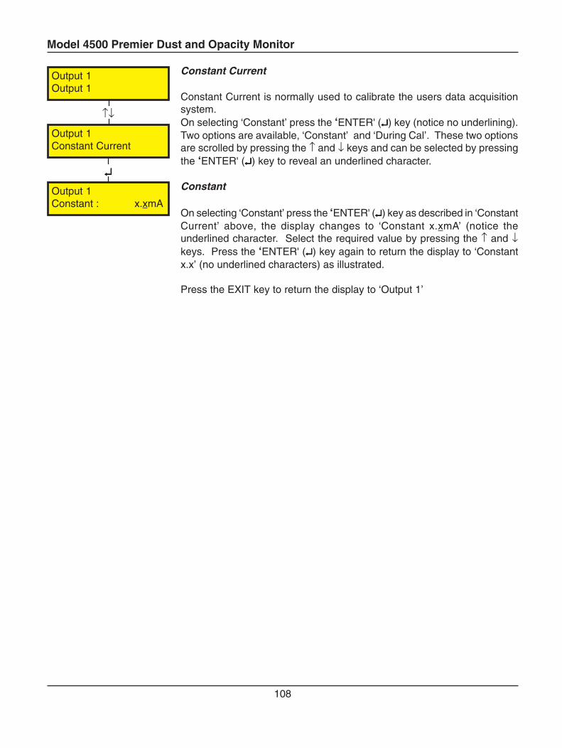
Model 4500 Premier Dust and Opacity Monitor
108
Constant Current
Constant Current is normally used to calibrate the users data acquisitionsystem.On selecting ‘Constant’ press the ‘ENTER' (↵↵↵↵↵) key (notice no underlining).Two options are available, ‘Constant’ and ‘During Cal’. These two optionsare scrolled by pressing the ↑ and ↓ keys and can be selected by pressingthe ‘ENTER' (↵↵↵↵↵) key to reveal an underlined character.
Constant
On selecting ‘Constant’ press the ‘ENTER' (↵↵↵↵↵) key as described in ‘ConstantCurrent’ above, the display changes to ‘Constant x.xmA’ (notice theunderlined character. Select the required value by pressing the ↑ and ↓keys. Press the ‘ENTER' (↵↵↵↵↵) key again to return the display to ‘Constantx.x’ (no underlined characters) as illustrated.
Press the EXIT key to return the display to ‘Output 1’
↵↵↵↵↵
↑↓
Output 1Output 1
Output 1Constant Current
Output 1Constant : x.xmA
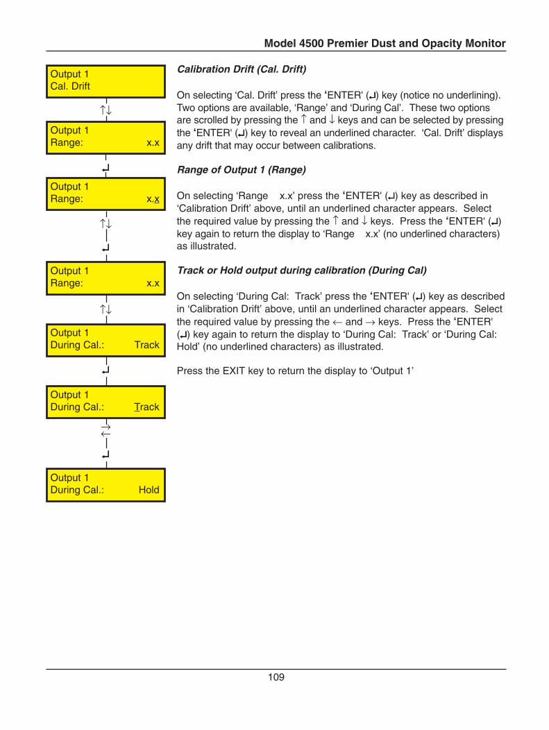
Model 4500 Premier Dust and Opacity Monitor
109
Calibration Drift (Cal. Drift)
On selecting ‘Cal. Drift’ press the ‘ENTER' (↵↵↵↵↵) key (notice no underlining).Two options are available, ‘Range’ and ‘During Cal’. These two optionsare scrolled by pressing the ↑ and ↓ keys and can be selected by pressingthe ‘ENTER' (↵↵↵↵↵) key to reveal an underlined character. ‘Cal. Drift’ displaysany drift that may occur between calibrations.
Range of Output 1 (Range)
On selecting ‘Range x.x’ press the ‘ENTER' (↵↵↵↵↵) key as described in‘Calibration Drift’ above, until an underlined character appears. Selectthe required value by pressing the ↑ and ↓ keys. Press the ‘ENTER' (↵↵↵↵↵)key again to return the display to ‘Range x.x’ (no underlined characters)as illustrated.
Track or Hold output during calibration (During Cal)
On selecting ‘During Cal: Track’ press the ‘ENTER' (↵↵↵↵↵) key as describedin ‘Calibration Drift’ above, until an underlined character appears. Selectthe required value by pressing the ← and → keys. Press the ‘ENTER'(↵↵↵↵↵) key again to return the display to ‘During Cal: Track’ or ‘During Cal:Hold’ (no underlined characters) as illustrated.
Press the EXIT key to return the display to ‘Output 1’
↵↵↵↵↵
↵↵↵↵↵
↑↓
↵↵↵↵↵
→←
↵↵↵↵↵
↑↓
↑↓
Output 1Cal. Drift
Output 1Range: x.x
Output 1Range: x.x
Output 1During Cal.: Hold
Output 1During Cal.: Track
Output 1During Cal.: Track
Output 1Range: x.x
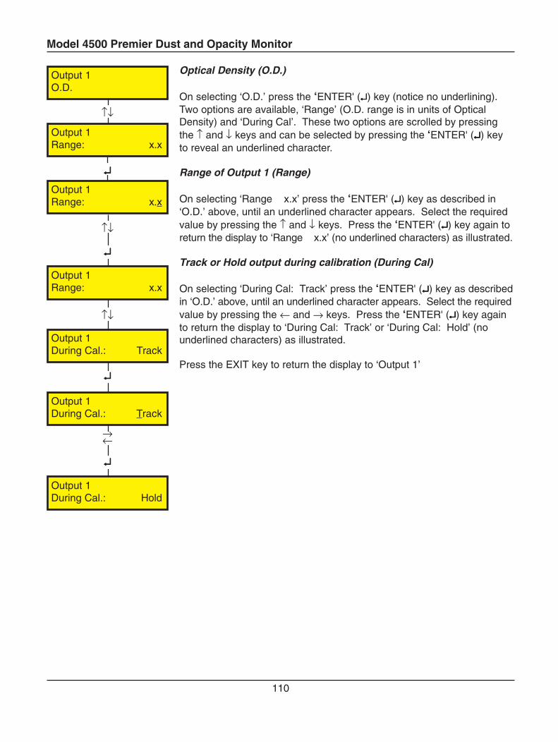
Model 4500 Premier Dust and Opacity Monitor
110
Optical Density (O.D.)
On selecting ‘O.D.’ press the ‘ENTER' (↵↵↵↵↵) key (notice no underlining).Two options are available, ‘Range’ (O.D. range is in units of OpticalDensity) and ‘During Cal’. These two options are scrolled by pressingthe ↑ and ↓ keys and can be selected by pressing the ‘ENTER' (↵↵↵↵↵) keyto reveal an underlined character.
Range of Output 1 (Range)
On selecting ‘Range x.x’ press the ‘ENTER' (↵↵↵↵↵) key as described in‘O.D.’ above, until an underlined character appears. Select the requiredvalue by pressing the ↑ and ↓ keys. Press the ‘ENTER' (↵↵↵↵↵) key again toreturn the display to ‘Range x.x’ (no underlined characters) as illustrated.
Track or Hold output during calibration (During Cal)
On selecting ‘During Cal: Track’ press the ‘ENTER' (↵↵↵↵↵) key as describedin ‘O.D.’ above, until an underlined character appears. Select the requiredvalue by pressing the ← and → keys. Press the ‘ENTER' (↵↵↵↵↵) key againto return the display to ‘During Cal: Track’ or ‘During Cal: Hold’ (nounderlined characters) as illustrated.
Press the EXIT key to return the display to ‘Output 1’
↵↵↵↵↵
↵↵↵↵↵
↑↓
↵↵↵↵↵
→←
↵↵↵↵↵
↑↓
↑↓
Output 1O.D.
Output 1Range: x.x
Output 1Range: x.x
Output 1During Cal.: Hold
Output 1During Cal.: Track
Output 1During Cal.: Track
Output 1Range: x.x
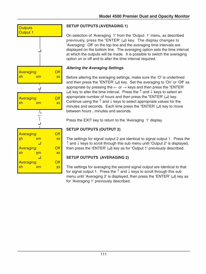
Model 4500 Premier Dust and Opacity Monitor
111
SETUP OUTPUTS (AVERAGING 1)
On selection of ‘Averaging 1’ from the ‘Output 1’ menu, as describedpreviously, press the ‘ENTER' (↵↵↵↵↵) key. The display changes to‘Averaging: Off’ on the top line and the averaging time intervals aredisplayed on the bottom line. The averaging option sets the time intervalat which the outputs will be made. It is possible to switch the averagingoption on or off and to alter the time interval required.
Altering the Averaging Settings
Before altering the averaging settings, make sure the ‘O’ is underlinedand then press the ‘ENTER' (↵↵↵↵↵) key. Set the averaging to ‘On’ or ‘Off’ asappropriate by pressing the ← or → keys and then press the ‘ENTER'(↵↵↵↵↵) key to alter the time interval. Press the ↑ and ↓ keys to select anappropriate number of hours and then press the ‘ENTER' (↵↵↵↵↵) key.Continue using the ↑ and ↓ keys to select appropriate values for theminutes and seconds. Each time press the ‘ENTER' (↵↵↵↵↵) key to movebetween hours , minutes and seconds.
Press the EXIT key to return to the ‘Averaging 1’ display.
SETUP OUTPUTS (OUTPUT 2)
The settings for signal output 2 are identical to signal output 1. Press the↑ and ↓ keys to scroll through this sub menu until ‘Output 2’ is displayed,then press the ‘ENTER’ (↵↵↵↵↵) key as for ‘Output 1’ previously described.
SETUP OUTPUTS (AVERAGING 2)
The settings for averaging the second signal output are identical to thatfor signal output 1. Press the ↑ and ↓ keys to scroll through this submenu until ‘Averaging 2’ is displayed, then press the ‘ENTER’ (↵↵↵↵↵) key asfor ‘Averaging 1’ previously described.
↵↵↵↵↵
→←
↵↵↵↵↵
↵↵↵↵↵
OutputsOutput 1
Averaging: Offxh xm xs
Averaging: Offxh xm xs
Averaging: Offxh xm xs
↵↵↵↵↵Averaging: Offxh xm xs
↵↵↵↵↵Averaging: Offxh xm xs
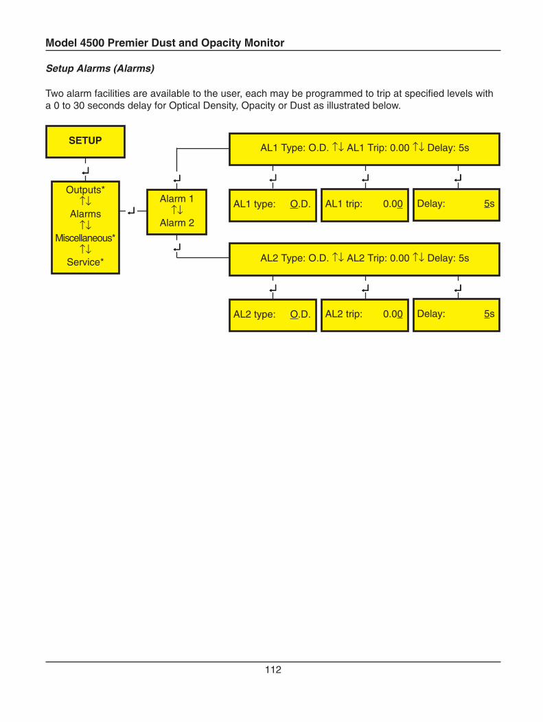
Model 4500 Premier Dust and Opacity Monitor
112
Setup Alarms (Alarms)
Two alarm facilities are available to the user, each may be programmed to trip at specified levels witha 0 to 30 seconds delay for Optical Density, Opacity or Dust as illustrated below.
↵↵↵↵↵
↵↵↵↵↵
↵↵↵↵↵ ↵↵↵↵↵ ↵↵↵↵↵
↵↵↵↵↵ ↵↵↵↵↵ ↵↵↵↵↵
↵↵↵↵↵
↵↵↵↵↵
SETUP
Outputs*↑↓
Alarms↑↓
Miscellaneous*↑↓
Service*
Alarm 1↑↓
Alarm 2
AL1 Type: O.D. ↑↓ AL1 Trip: 0.00 ↑↓ Delay: 5s
AL1 type: O.D. AL1 trip: 0.00 Delay: 5s
AL2 Type: O.D. ↑↓ AL2 Trip: 0.00 ↑↓ Delay: 5s
AL2 type: O.D. AL2 trip: 0.00 Delay: 5s
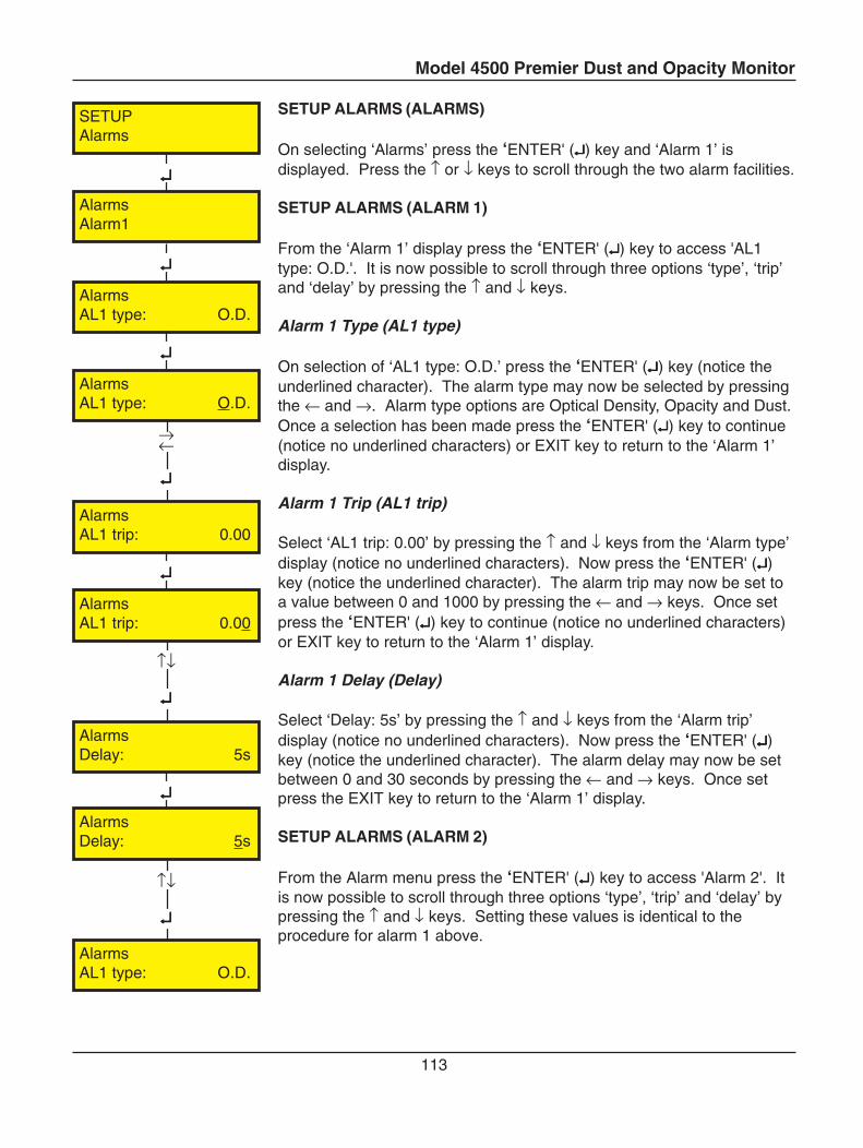
Model 4500 Premier Dust and Opacity Monitor
113
SETUP ALARMS (ALARMS)
On selecting ‘Alarms’ press the ‘ENTER' (↵↵↵↵↵) key and ‘Alarm 1’ isdisplayed. Press the ↑ or ↓ keys to scroll through the two alarm facilities.
SETUP ALARMS (ALARM 1)
From the ‘Alarm 1’ display press the ‘ENTER' (↵↵↵↵↵) key to access 'AL1type: O.D.'. It is now possible to scroll through three options ‘type’, ‘trip’and ‘delay’ by pressing the ↑ and ↓ keys.
Alarm 1 Type (AL1 type)
On selection of ‘AL1 type: O.D.’ press the ‘ENTER' (↵↵↵↵↵) key (notice theunderlined character). The alarm type may now be selected by pressingthe ← and →. Alarm type options are Optical Density, Opacity and Dust.Once a selection has been made press the ‘ENTER' (↵↵↵↵↵) key to continue(notice no underlined characters) or EXIT key to return to the ‘Alarm 1’display.
Alarm 1 Trip (AL1 trip)
Select ‘AL1 trip: 0.00’ by pressing the ↑ and ↓ keys from the ‘Alarm type’display (notice no underlined characters). Now press the ‘ENTER' (↵↵↵↵↵)key (notice the underlined character). The alarm trip may now be set toa value between 0 and 1000 by pressing the ← and → keys. Once setpress the ‘ENTER' (↵↵↵↵↵) key to continue (notice no underlined characters)or EXIT key to return to the ‘Alarm 1’ display.
Alarm 1 Delay (Delay)
Select ‘Delay: 5s’ by pressing the ↑ and ↓ keys from the ‘Alarm trip’display (notice no underlined characters). Now press the ‘ENTER' (↵↵↵↵↵)key (notice the underlined character). The alarm delay may now be setbetween 0 and 30 seconds by pressing the ← and → keys. Once setpress the EXIT key to return to the ‘Alarm 1’ display.
SETUP ALARMS (ALARM 2)
From the Alarm menu press the ‘ENTER' (↵↵↵↵↵) key to access 'Alarm 2'. Itis now possible to scroll through three options ‘type’, ‘trip’ and ‘delay’ bypressing the ↑ and ↓ keys. Setting these values is identical to theprocedure for alarm 1 above.
↵↵↵↵↵
↵↵↵↵↵
↑↓
↵↵↵↵↵
↵↵↵↵↵
↵↵↵↵↵
→←
↵↵↵↵↵
↵↵↵↵↵
↑↓
↵↵↵↵↵
SETUPAlarms
AlarmsAlarm1
AlarmsAL1 type: O.D.
AlarmsAL1 type: O.D.
AlarmsAL1 trip: 0.00
AlarmsAL1 trip: 0.00
AlarmsDelay: 5s
AlarmsDelay: 5s
AlarmsAL1 type: O.D.
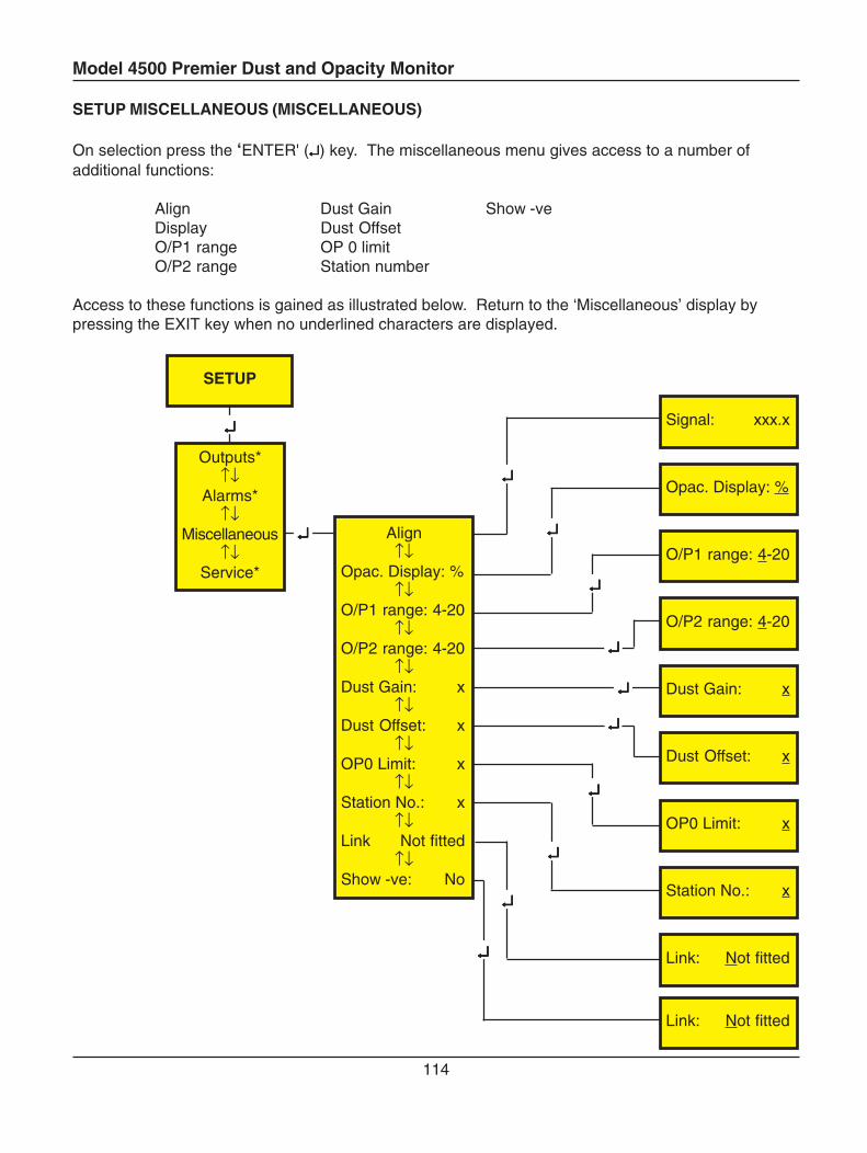
Model 4500 Premier Dust and Opacity Monitor
114
SETUP MISCELLANEOUS (MISCELLANEOUS)
On selection press the ‘ENTER' (↵↵↵↵↵) key. The miscellaneous menu gives access to a number ofadditional functions:
Align Dust Gain Show -veDisplay Dust OffsetO/P1 range OP 0 limitO/P2 range Station number
Access to these functions is gained as illustrated below. Return to the ‘Miscellaneous’ display bypressing the EXIT key when no underlined characters are displayed.
↵↵↵↵↵
↵↵↵↵↵
SETUP
Outputs*↑↓
Alarms*↑↓
Miscellaneous↑↓
Service*
↵↵↵↵↵
↵↵↵↵↵
↵↵↵↵↵
↵↵↵↵↵
↵↵↵↵↵
↵↵↵↵↵
↵↵↵↵↵
↵↵↵↵↵
↵↵↵↵↵ Station No.: x
Dust Gain: x
Dust Offset: x
OP0 Limit: x
Link: Not fitted
Signal: xxx.x
Opac. Display: %
O/P1 range: 4-20
O/P2 range: 4-20
Align↑↓
Opac. Display: %↑↓
O/P1 range: 4-20↑↓
O/P2 range: 4-20↑↓
Dust Gain: x↑↓
Dust Offset: x↑↓
OP0 Limit: x↑↓
Station No.: x↑↓
Link Not fitted↑↓
Show -ve: No
Link: Not fitted
↵↵↵↵↵
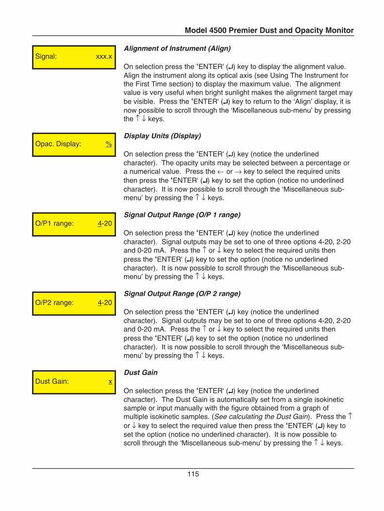
Model 4500 Premier Dust and Opacity Monitor
115
Alignment of Instrument (Align)
On selection press the ‘ENTER' (↵↵↵↵↵) key to display the alignment value.Align the instrument along its optical axis (see Using The Instrument forthe First Time section) to display the maximum value. The alignmentvalue is very useful when bright sunlight makes the alignment target maybe visible. Press the ‘ENTER' (↵↵↵↵↵) key to return to the ‘Align’ display, it isnow possible to scroll through the ‘Miscellaneous sub-menu’ by pressingthe ↑ ↓ keys.
Display Units (Display)
On selection press the ‘ENTER' (↵↵↵↵↵) key (notice the underlinedcharacter). The opacity units may be selected between a percentage ora numerical value. Press the ← or → key to select the required unitsthen press the ‘ENTER' (↵↵↵↵↵) key to set the option (notice no underlinedcharacter). It is now possible to scroll through the ‘Miscellaneous sub-menu’ by pressing the ↑ ↓ keys.
Signal Output Range (O/P 1 range)
On selection press the ‘ENTER' (↵↵↵↵↵) key (notice the underlinedcharacter). Signal outputs may be set to one of three options 4-20, 2-20and 0-20 mA. Press the ↑ or ↓ key to select the required units thenpress the ‘ENTER' (↵↵↵↵↵) key to set the option (notice no underlinedcharacter). It is now possible to scroll through the ‘Miscellaneous sub-menu’ by pressing the ↑ ↓ keys.
Signal Output Range (O/P 2 range)
On selection press the ‘ENTER' (↵↵↵↵↵) key (notice the underlinedcharacter). Signal outputs may be set to one of three options 4-20, 2-20and 0-20 mA. Press the ↑ or ↓ key to select the required units thenpress the ‘ENTER' (↵↵↵↵↵) key to set the option (notice no underlinedcharacter). It is now possible to scroll through the ‘Miscellaneous sub-menu’ by pressing the ↑ ↓ keys.
Dust Gain
On selection press the ‘ENTER' (↵↵↵↵↵) key (notice the underlinedcharacter). The Dust Gain is automatically set from a single isokineticsample or input manually with the figure obtained from a graph ofmultiple isokinetic samples. (See calculating the Dust Gain). Press the ↑or ↓ key to select the required value then press the ‘ENTER' (↵↵↵↵↵) key toset the option (notice no underlined character). It is now possible toscroll through the ‘Miscellaneous sub-menu’ by pressing the ↑ ↓ keys.
Opac. Display: %
O/P1 range: 4-20
O/P2 range: 4-20
Dust Gain: x
Signal: xxx.x
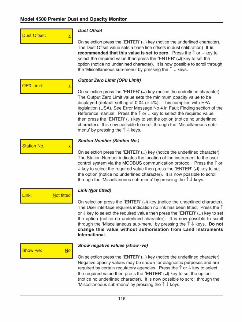
Model 4500 Premier Dust and Opacity Monitor
116
Dust Offset
On selection press the ‘ENTER' (↵↵↵↵↵) key (notice the underlined character).The Dust Offset value sets a base line offsets in dust calibration) It isrecommended that this value is set to zero. Press the ↑ or ↓ key toselect the required value then press the ‘ENTER' (↵↵↵↵↵) key to set theoption (notice no underlined character). It is now possible to scroll throughthe ‘Miscellaneous sub-menu’ by pressing the ↑ ↓ keys.
Output Zero Limit (OP0 Limit)
On selection press the ‘ENTER' (↵↵↵↵↵) key (notice the underlined character).The Output Zero Limit value sets the minimum opacity value to bedisplayed (default setting of 0.04 or 4%). This complies with EPAlegislation (USA). See Error Message No 4 in Fault Finding section of theReference manual. Press the ↑ or ↓ key to select the required valuethen press the ‘ENTER' (↵↵↵↵↵) key to set the option (notice no underlinedcharacter). It is now possible to scroll through the ‘Miscellaneous sub-menu’ by pressing the ↑ ↓ keys.
Station Number (Station No.)
On selection press the ‘ENTER' (↵↵↵↵↵) key (notice the underlined character).The Station Number indicates the location of the instrument to the usercontrol system via the MODBUS communication protocol. Press the ↑ or↓ key to select the required value then press the ‘ENTER' (↵↵↵↵↵) key to setthe option (notice no underlined character). It is now possible to scrollthrough the ‘Miscellaneous sub-menu’ by pressing the ↑ ↓ keys.
Link (Not fitted)
On selection press the ‘ENTER' (↵↵↵↵↵) key (notice the underlined character).The User interface requires indication no link has been fitted. Press the ↑or ↓ key to select the required value then press the ‘ENTER' (↵↵↵↵↵) key to setthe option (notice no underlined character). It is now possible to scrollthrough the ‘Miscellaneous sub-menu’ by pressing the ↑ ↓ keys. Do notchange this value without authorisation from Land InstrumentsInternational.
Show negative values (show -ve)
On selection press the ‘ENTER' (↵↵↵↵↵) key (notice the underlined character).Negative opacity values may be shown for diagnostic purposes and arerequired by certain regulatory agencies. Press the ↑ or ↓ key to selectthe required value then press the ‘ENTER' (↵↵↵↵↵) key to set the option(notice no underlined character). It is now possible to scroll through the‘Miscellaneous sub-menu’ by pressing the ↑ ↓ keys.
Dust Offset: x
OP0 Limit: x
Station No.: x
Link: Not fitted
Show -ve: No
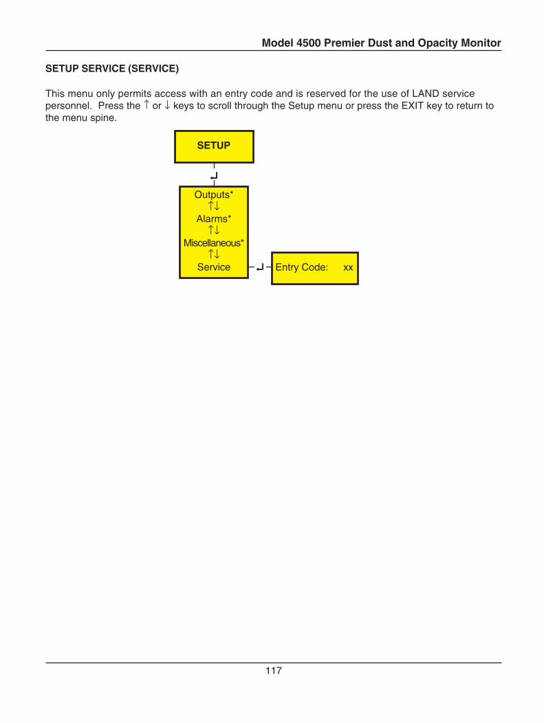
Model 4500 Premier Dust and Opacity Monitor
117
SETUP SERVICE (SERVICE)
This menu only permits access with an entry code and is reserved for the use of LAND servicepersonnel. Press the ↑ or ↓ keys to scroll through the Setup menu or press the EXIT key to return tothe menu spine.
↵↵↵↵↵
↵↵↵↵↵
SETUP
Outputs*↑↓
Alarms*↑↓
Miscellaneous*↑↓
Service Entry Code: xx
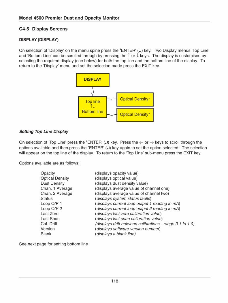
Model 4500 Premier Dust and Opacity Monitor
118
C4-5 Display Screens
DISPLAY (DISPLAY)
On selection of ‘Display’ on the menu spine press the ‘ENTER' (↵↵↵↵↵) key. Two Display menus ‘Top Line’and ‘Bottom Line’ can be scrolled through by pressing the ↑ or ↓ keys. The display is customised byselecting the required display (see below) for both the top line and the bottom line of the display. Toreturn to the ‘Display’ menu and set the selection made press the EXIT key.
Setting Top Line Display
On selection of ‘Top Line’ press the ‘ENTER' (↵↵↵↵↵) key. Press the ← or → keys to scroll through theoptions available and then press the ‘ENTER' (↵↵↵↵↵) key again to set the option selected. The selectionwill appear on the top line of the display. To return to the ‘Top Line’ sub-menu press the EXIT key.
Options available are as follows:
Opacity (displays opacity value)Optical Density (displays optical value)Dust Density (displays dust density value)Chan. 1 Average (displays average value of channel one)Chan. 2 Average (displays average value of channel two)Status (displays system status faults)Loop O/P 1 (displays current loop output 1 reading in mA)Loop O/P 2 (displays current loop output 2 reading in mA)Last Zero (displays last zero calibration value)Last Span (displays last span calibration value)Cal. Drift (displays drift between calibrations - range 0.1 to 1.0)Version (displays software version number)Blank (displays a blank line)
See next page for setting bottom line
↵↵↵↵↵↵↵↵↵↵
↵↵↵↵↵
DISPLAY
Top line↑↓
Bottom line
Optical Density*
Optical Density*
Model 4500 Premier Dust and Opacity Monitor
119
Setting Bottom Line Display
On selection of ‘Bottom Line’ press the ‘ENTER' (↵↵↵↵↵) key. Press the ← or → keys to scroll through theoptions available and then press the ‘ENTER' (↵↵↵↵↵) key again to set the option selected. The displaywill not change until the maintenance switch has been returned to the RUN (vertical) position. Toreturn to the ‘Bottom Line’ sub-menu press the EXIT key.
Options available are as follows:
Opacity (displays opacity value)Optical Density (displays optical value)Dust Density (displays dust density value)Chan. 1 Average (displays average value of channel one)Chan. 2 Average (displays average value of channel two)Status (displays system status faults)Loop O/P 1 (displays current loop output 1 reading in mA)Loop O/P 2 (displays current loop output 2 reading in mA)Last Zero (displays last zero calibration value)Last Span (displays last span calibration value)Cal. Drift (displays drift between calibrations - range 0.1 to 1.0)Version (displays software version number)Blank (displays a blank line)
Model 4500 Premier Dust and Opacity Monitor
120
↵↵↵↵↵
PARAMETERS
SO*
C4-6 Parameter Screens
PARAMETERS
This menu contains the Model 4500 Premier internal parameters and isused as a general software dump with updated readings. It is not normallyintended for customer use, but may be useful for diagnosing particularproblems.
On selection of ‘Parameters’ on the menu spine press the ‘ENTER' (↵↵↵↵↵)key. Press the ↑ or ↓ keys to scroll through the parameters available forviewing, as detailed below.
So ...................... Signal detector offsetSf ....................... Signal detector flood valueSm ..................... Signal detector measurementRo...................... Reference detector offsetRf....................... Reference detector flood valueRm..................... Reference detector measurementC........................ Dust concentrationX ........................ Calibration constantB ........................ Balance correctionG ....................... Gain correction factorQ ....................... Uncorrected transmission factorDust Gain .......... Constant relating Optical Density to Dust Density.Dust Offset ........ Optical Density v Dust Density zero offset (usually zero)Zero Damper ..... Low pass digital filter applied to zero readingFlood Damper ... Low pass digital filter applied to flood LEDCal Damper ....... Low pass digital filter applied to calibrationOP 1 Damper .... Low pass digital filter applied to output 1OP 2 Damper .... Low pass digital filter applied to output 2PLCF ................. Path Length Correction FactorOPLR ................ Optical Path Length Ratio (0.5 x PLCF)Last Cal. ............ Data stored from the latest calibrationZero Comp. ....... Opacity compensation due to dust build on the lensIsokinetic O.D. ... Optical Density Calculated IsometricallyVersion x.xx ....... Identification of software version used
Model 4500 Premier Dust and Opacity Monitor
121
C5 System Specification
C5-1 4500 Premier Dust and Opacity Monitor
Measuring
Technique: Double pass/path transmissometry
Operating Wavelength: 520 ± 20 nm
Light Source: High Intensity LED
Range: Opacity 0 – 10 % to 0 – 100 %Optical Density 0 – 0.1 to 0 – 3.0Dust Density 0-10 to 0 to 4000 mg/m3
User Selectable
Linearity: < 2 % of range
Resolution: 0.1 % Opacity; 0.001 Optical Density; 0.1 mg/m3 Dust
Drift: < 3 % of range per month
Angle of Projection: < 2 o
Angle of View: < 2 o
Response Time: 1 second to 90 % of final value
Averaging: Selectable from 10 seconds to 24 hours (in 1 second steps)
Pathlength: 0.7 to 10 m / 2 to 33 ft (option up to 20 m / 66 ft)
Calibration: Automatic zero and upscale calibration(Selectable interval 1 to 24 hours in 1 hour steps)
Zero Correction: Automatic correction for zero drift
Control Panel
Display: 2 x 16 character reflective backlit LCD with adjustable contrast control
Keypad: 7 keys for data input
Indicators: System OK, Alarm 1, Alarm 2, Zero calibration, Span calibration
Model 4500 Premier Dust and Opacity Monitor
122
Environmental
Operating temperature: -20 to 55 oC / -4 to 131 oF(-40 oC / -40 oF with optional heater)
Maximum Flue Gas temperature: 600 oC / 1112 oF
Maximum Flange Temp: 200 oC / 392 oF
Environmental rating: IP66 / NEMA4X
Compliance
Measurement standards: Meets or exceeds US EPA requirements for 40CFR60Sections 13, 17 and App. B PS1Meets or exceeds US EPA requirements for proposed40CFR60 App. F Procedure 3Meets or exceeds ASTM Standard D6216 - 98Meets or exceeds US EPA CPS-001
Safety: Conforms to EN-61010-2
EMC: Conforms to E-50 081 & EN-50 082
Outputs
Modbus Interface: RS232 or RS485. Opacity, Dust, Optical Density, Status,Averaging and Range information available
Analogue Outputs: Two isolated 4-20mA current outputs.Independently configurable as Opacity, Dust Optical Density,Calibration Drift or PLCF
Relay Outputs: System OK, Span calibration, Zero calibration, Alarm 1,Alarm 2, Maintenance
Continuous product development may make it necessary to change these details without notice
Model 4500 Premier Dust and Opacity Monitor
123
Termination Box
Modbus Interface: RS232 or RS485 Multi-dropOpacity, Dust, Optical Density, Status, Averagingand Range Information availableCalibration sequence trigger
Analogue Outputs : Two 4-20mA current loops, fully isolated 50 V d.c.Independently configurable as: Opacity, Dust,Optical Density or Calibration Drift
Relay Outputs: System OK, Span Calibration, Zero Calibration,Alarm 1, Alarm 2, Maintenance
Relay Rating: Single Pole Changeover2A at 40 V d.c.; 2A at 230 V a.c.
Standard Termination BoxPower Supply: 90 to 260 V a.c. (universal input), 50 to 60 HzPower Consumption: 10 W
Heated Termination BoxPower Supply: 115 / 230 V a.c. (dual voltage, selectable) 50 to 60 HzPower Consumption: 60 W
Installation Category: Category II
Electromagnetic Compliance: Conforms to EN50 081-2; EN50 082-2
Operating Temperature: -20 to +55°C (-4 to +131°F)
Dimensions (H x W x D): 180 x 400 x 120 mm (7 x 16 x 5 inches)
Weight: 7.5 kg (16.5 lb)
Continuous product development may make it necessary to change these details without notice
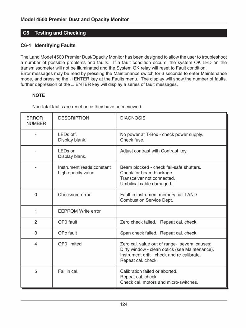
Model 4500 Premier Dust and Opacity Monitor
124
C6 Testing and Checking
C6-1 Identifying Faults
The Land Model 4500 Premier Dust/Opacity Monitor has been designed to allow the user to troubleshoota number of possible problems and faults. If a fault condition occurs, the system OK LED on thetransmissometer will not be illuminated and the System OK relay will reset to Fault condition.Error messages may be read by pressing the Maintenance switch for 3 seconds to enter Maintenancemode, and pressing the ↵ ENTER key at the Faults menu. The display will show the number of faults,further depression of the ↵ ENTER key will display a series of fault messages.
NOTE
Non-fatal faults are reset once they have been viewed.
ERROR DESCRIPTION DIAGNOSISNUMBER
- LEDs off. No power at T-Box - check power supply.Display blank. Check fuse.
- LEDs on Adjust contrast with Contrast key.Display blank.
- Instrument reads constant Beam blocked - check fail-safe shutters.high opacity value Check for beam blockage.
Transceiver not connected.Umbilical cable damaged.
0 Checksum error Fault in instrument memory call LANDCombustion Service Dept.
1 EEPROM Write error
2 OP0 fault Zero check failed. Repeat cal. check.
3 OPc fault Span check failed. Repeat cal. check.
4 OP0 limited Zero cal. value out of range- several causes:Dirty window - clean optics (see Maintenance).Instrument drift - check and re-calibrate.Repeat cal. check.
5 Fail in cal. Calibration failed or aborted.Repeat cal. check.Check cal. motors and micro-switches.
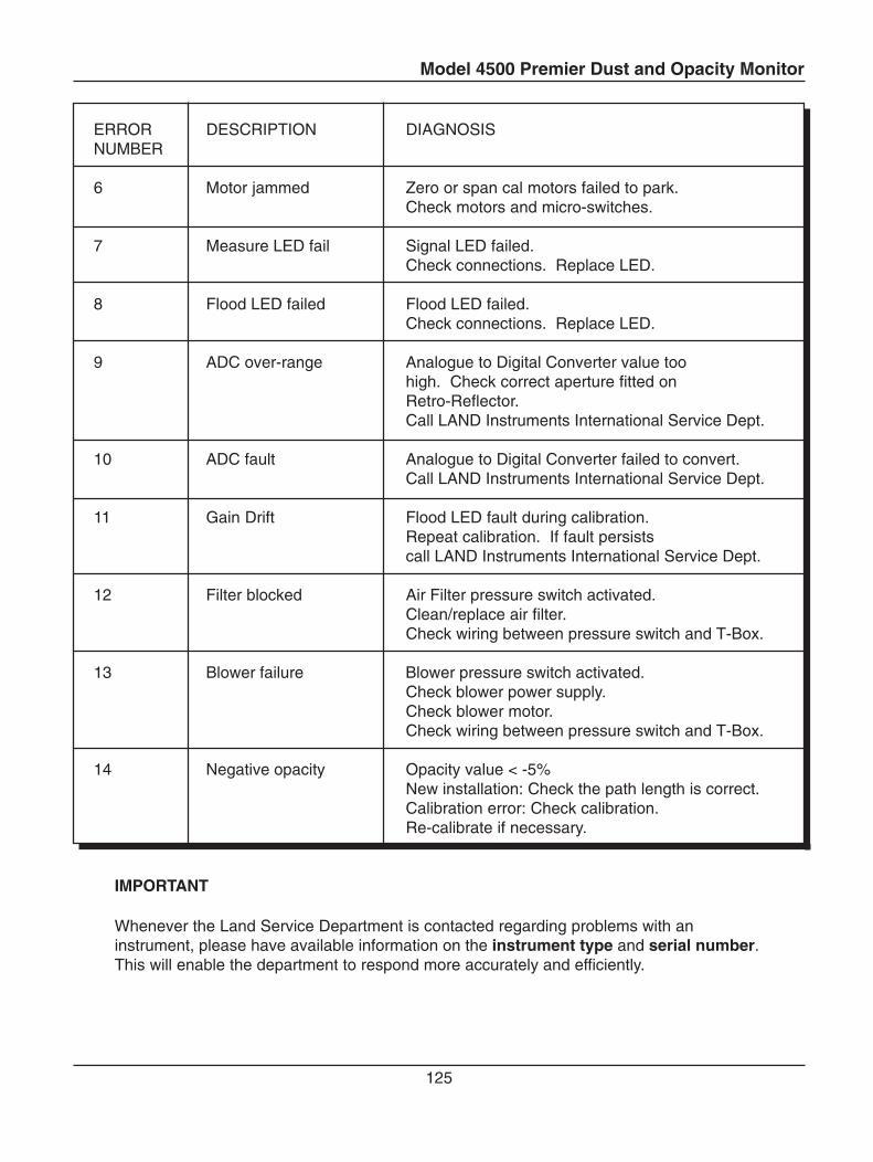
Model 4500 Premier Dust and Opacity Monitor
125
ERROR DESCRIPTION DIAGNOSISNUMBER
6 Motor jammed Zero or span cal motors failed to park.Check motors and micro-switches.
7 Measure LED fail Signal LED failed.Check connections. Replace LED.
8 Flood LED failed Flood LED failed.Check connections. Replace LED.
9 ADC over-range Analogue to Digital Converter value toohigh. Check correct aperture fitted onRetro-Reflector.Call LAND Instruments International Service Dept.
10 ADC fault Analogue to Digital Converter failed to convert.Call LAND Instruments International Service Dept.
11 Gain Drift Flood LED fault during calibration.Repeat calibration. If fault persistscall LAND Instruments International Service Dept.
12 Filter blocked Air Filter pressure switch activated.Clean/replace air filter.Check wiring between pressure switch and T-Box.
13 Blower failure Blower pressure switch activated.Check blower power supply.Check blower motor.Check wiring between pressure switch and T-Box.
14 Negative opacity Opacity value < -5%New installation: Check the path length is correct.Calibration error: Check calibration.Re-calibrate if necessary.
IMPORTANT
Whenever the Land Service Department is contacted regarding problems with aninstrument, please have available information on the instrument type and serial number.This will enable the department to respond more accurately and efficiently.
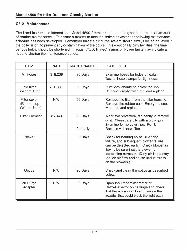
Model 4500 Premier Dust and Opacity Monitor
126
C6-2 Maintenance
The Land Instruments International Model 4500 Premier has been designed for a minimal amountof routine maintenance . To ensure a maximum monitor lifetime however, the following maintenanceschedule has been developed. Remember that the air purge system should always be left on, even ifthe boiler is off, to prevent any contamination of the optics. In exceptionally dirty facilities, the timeperiods below should be shortened. Frequent “Op0 limited” alarms or blower faults may indicate aneed to shorten the maintenance period.
ITEM PART MAINTENANCE PROCEDURE
Air Hoses 318.239 90 Days Examine hoses for holes or leaks.Test all hose clamps for tightness.
Pre-filter 701.983 90 Days Dust level should be below the line.(Where fitted) Remove, empty, wipe out, and replace.
Filter cover N/A 90 Days Remove the filter from the filter housing./Rubber cup Remove the rubber cup. Empty the cup,(Where fitted) wipe out, and replace.
Filter Element 317.441 90 Days Wear eye protection, tap gently to removedust. Clean carefully with a blow gun.Examine for holes or rips. Re-fit.
Annually Replace with new filter.
Blower 90 Days Check for bearing noise. (Bearingfailure, and subsequent blower failure,can be detected early.) Check blower airflow to be sure that the blower isperforming normally. (Dirty air filters mayreduce air flow and cause undue stresson the blowers.)
Optics N/A 90 Days Check and clean the optics as describedbelow.
Air Purge N/A 90 Days Open the Transmissometer orAdapter Retro-Reflector on its hinge and check
that there is no ash buildup inside theadapter that could block the light path.
Model 4500 Premier Dust and Opacity Monitor
127
During the regularly scheduled maintenance periods, any optional equipment (e.g. shutters, pressureswitches, weathercovers) should be checked for correct operation. If any potential problems arenoted, the equipment should be repaired or replaced if necessary.
Cleaning the Optical Surfaces
After prolonged use, it is likely that some contamination will occur on the optical surfaces of the Model4500 Premier. The time taken for significant contamination to occur depends very much on the nature ofthe installation, but in a typical situation it should be sufficient to clean the optics every 90 days. Threeoptical components should be cleaned, using the lens cloth supplied by Land Instruments International.
CAUTION
Always use a lint free lens cloth to clean the optical surfaces. Ensure the cloth iskept clean. A dirty lens cloth can scratch the optical surface and cause permanentdamage to the Model 4500 Premier. Replacement lens cloths can be purchasedfrom Land Instruments International. Ordinary tissues and dusters are notsuitable, and can scratch the delicate optical surfaces.
To clean the Retro-Reflector, open the housing by undoing the two quick-release clamps. Carefullywipe the glass surface of the Retro-Reflector with the lens cloth. Close the housing and fasten the twoquick-release clamps.
To clean the mains lens, open the Transmissometer housing by undoing the two quick-releaseclamps. Undo the two socket headed, captive screws holding the zero-point assembly and carefullyremove it. Wipe the lens using the lens cloth, then replace the zero-point assembly. Lift the spring-loaded protective cover over the zero-point reflector and wipe the reflector. Gently replace theprotective cover. Close the housing and fasten the quick-release clamps.
CAUTION
Do not attempt to move the zero-point reflector by hand. The precision gearboxwill be irreparably damaged.
Cleaning the Termination Box
It is recommended to periodically clean the termination box to remove any build-up of dirt or dust,which may enter the box if the door is opened.

Model 4500 Premier Dust and Opacity Monitor
128
Changing the pathlength
The Model 4500 Premier has been configured and tested for the pathlength specified at the time ofpurchase. Changing its pathlength will alter its calibration and may invalidate any certificate of compliance.Do not change the installation pathlength without authorization from Land Instruments International.
Tools required2.5 mm hex (Allen) key5 mm hex (Allen) key - supplied
Set the correct focus1. Open the transceiver housing by undoing the two quick-release clamps.
2. Undo the two socket headed, captive screws holding the zero-point assembly and carefullyremove it. Mark the top of the lens assembly.
3. Undo the 3 M4 socket headed screws holding the lens assembly. NB These screws are NOTcaptive.
4. Carefully remove the lens assembly, taking care not to touch the lens surface.
5. Remove the o-ring from the lens and remove the focus spacers. There are 3 spacers, withthicknesses 2 mm, 4 mm and 8 mm. Select the appropriate spacers to give the correct focusdistance for the flange-to-flange pathlength shown in the table.
6. Replace the O-ring on the lens assembly.
7. Select the correct length of M3 fixing screws for the flange-to-flange pathlength shown in thetable. Carefully place the screws into the holes in the lens assembly, making sure that theypass through the holes in the focus spacers.
8. Slide the lens assembly into place. Ensureing the orientation is the same as when removed.
9. Fasten all of the screws using a 2.5 mm hex (Allen) key.
10. Replace the zero-point assembly.
11. Close the housing and fasten the quick-release clamps.
Fit the correct retroreflector.1. Open the retroreflector housing by undoing the two quick-release clamps.2. Undo the two M3 socket headed screws holding the retroreflector assembly and carefully
remove it. NB These screws are NOT captive.3. Select the correct retroreflector for the flange-to-flange pathlength shown in the table. Fit the
retroreflector using the M3 socket-head screws.4. Close the housing and fasten the quick-release clamps.
Perform a clear stack calibration at the new pathlength – see B3-3
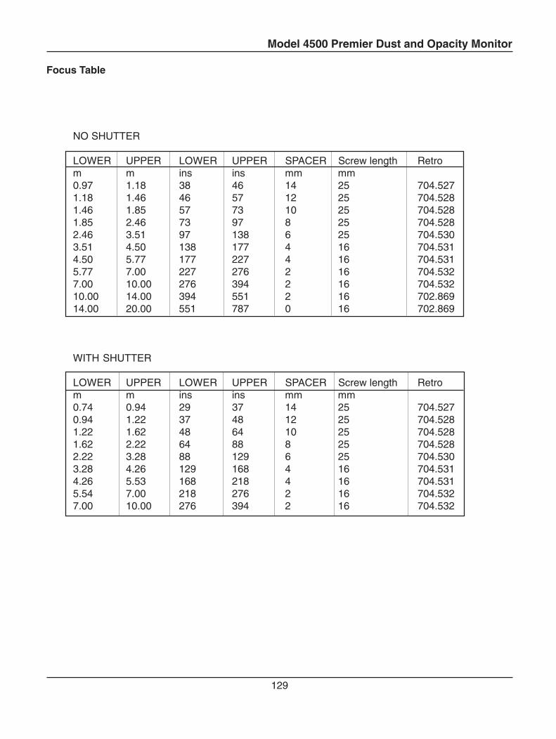
Model 4500 Premier Dust and Opacity Monitor
129
NO SHUTTER
LOWER UPPER LOWER UPPER SPACER Screw length Retrom m ins ins mm mm0.97 1.18 38 46 14 25 704.5271.18 1.46 46 57 12 25 704.5281.46 1.85 57 73 10 25 704.5281.85 2.46 73 97 8 25 704.5282.46 3.51 97 138 6 25 704.5303.51 4.50 138 177 4 16 704.5314.50 5.77 177 227 4 16 704.5315.77 7.00 227 276 2 16 704.5327.00 10.00 276 394 2 16 704.53210.00 14.00 394 551 2 16 702.86914.00 20.00 551 787 0 16 702.869
WITH SHUTTER
LOWER UPPER LOWER UPPER SPACER Screw length Retrom m ins ins mm mm0.74 0.94 29 37 14 25 704.5270.94 1.22 37 48 12 25 704.5281.22 1.62 48 64 10 25 704.5281.62 2.22 64 88 8 25 704.5282.22 3.28 88 129 6 25 704.5303.28 4.26 129 168 4 16 704.5314.26 5.53 168 218 4 16 704.5315.54 7.00 218 276 2 16 704.5327.00 10.00 276 394 2 16 704.532
Focus Table
Model 4500 Premier Dust and Opacity Monitor
130
C6-3 Replacement Parts and Consumables
Consumables
Description .......................................................................... Part Number
Lens cloth................................................................................... 320.804Flange Sealing Ring .................................................................. 701.981
Spares Parts
Spherical Washers ..................................................................... 702.749Spring washer ............................................................................ 318.284M12 Locknuts ............................................................................ 315.040Flange Stud ............................................................................... 702.755Microprocessor Module PCB ..................................................... 702.762Signal Processor PCB ............................................................... 702.684Measurement Detector PCB ...................................................... 702.645Reference Detector PCB ........................................................... 702.648Source LED PCB ....................................................................... 702.688Flood LED PCB.......................................................................... 702.691Air Purge Diffuser ...................................................................... 700.911*Reflector Assembly .................................................................. 704.527*Reflector Assembly .................................................................. 704.528*Reflector Assembly .................................................................. 704.530*Reflector Assembly .................................................................. 704.531*Reflector Assembly .................................................................. 704.532*Reflector Assembly .................................................................. 702.869Zero Calibration Assembly ......................................................... 702.778Zero Calibration Motor Assembly............................................... 702.833Zero Calibration Micro Switch Assembly ................................... 702.832Mains Lens Assembly ................................................................ 702.781Upscale Calibration Assembly ................................................... 702.777Upscale Calibration Motor Assembly ......................................... 702.817Upscale Calibration Micro Switch Assembly .............................. 406.007Calibration Grating Set .............................................................. 703.803Reflector Aperture Set ............................................................... 703.793Termination Box PCB (Not including enclosure) ........................ 704.226Termination Box PCB (Heated version) (Not incl. enclosure)..... 704.273Transceiver cover fitted with key panel + connectors ................ 704.271Control Panel PCB ..................................................................... 704.171
2 Year Spares Kit ....................................................................... 775.006
* See table for details of reflector assemblies.
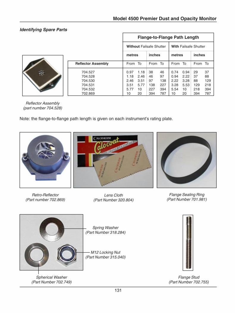
Model 4500 Premier Dust and Opacity Monitor
131
Identifying Spare Parts
Spherical Washer(Part Number 702.749)
Spring Washer(Part Number 318.284)
M12 Locking Nut(Part Number 315.040)
Flange Stud(Part Number 702.755)
Lens Cloth(Part Number 320.804)
Flange Sealing Ring(Part Number 701.981)
Reflector Assembly(part number 704.528)
Note: the flange-to-flange path length is given on each instrument’s rating plate.
Flange-to-Flange Path Length
Without Failsafe Shutter With Failsafe Shutter
metres inches metres inches
Reflector Assembly From To From To From To From To
704.527 0.97 1.18 38 46 0.74 0.94 29 37704.528 1.18 2.46 46 97 0.94 2.22 37 88704.530 2.46 3.51 97 138 2.22 3.28 88 129704.531 3.51 5.77 138 227 3.28 5.53 129 218704.532 5.77 10 227 394 5.54 10 218 394702.869 10 20 394 787 10 20 394 787
Retro-Reflector(Part number 702.869)
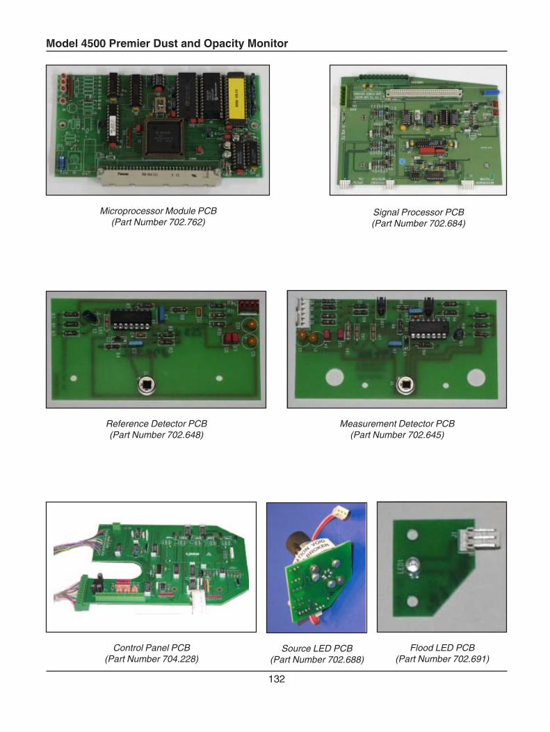
Model 4500 Premier Dust and Opacity Monitor
132
Microprocessor Module PCB(Part Number 702.762)
Reference Detector PCB(Part Number 702.648)
Measurement Detector PCB(Part Number 702.645)
Flood LED PCB(Part Number 702.691)
Source LED PCB(Part Number 702.688)
Control Panel PCB(Part Number 704.228)
Signal Processor PCB(Part Number 702.684)
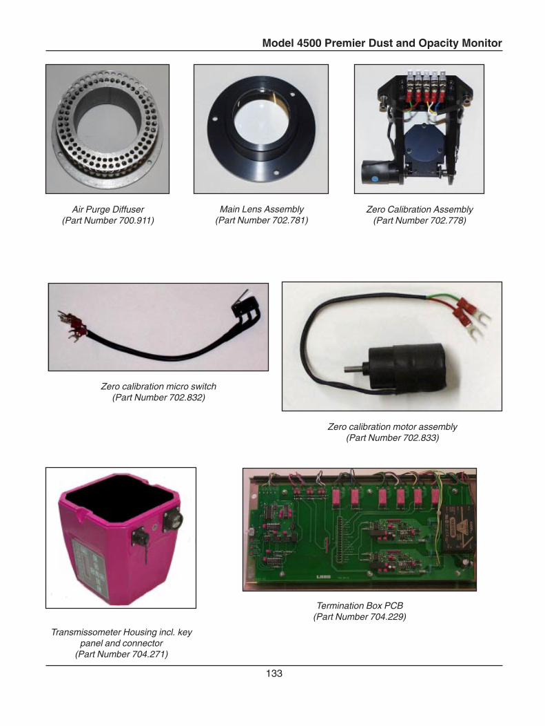
Model 4500 Premier Dust and Opacity Monitor
133
Termination Box PCB(Part Number 704.229)
Zero calibration micro switch(Part Number 702.832)
Air Purge Diffuser(Part Number 700.911)
Main Lens Assembly(Part Number 702.781)
Zero Calibration Assembly(Part Number 702.778)
Zero calibration motor assembly(Part Number 702.833)
Transmissometer Housing incl. keypanel and connector
(Part Number 704.271)
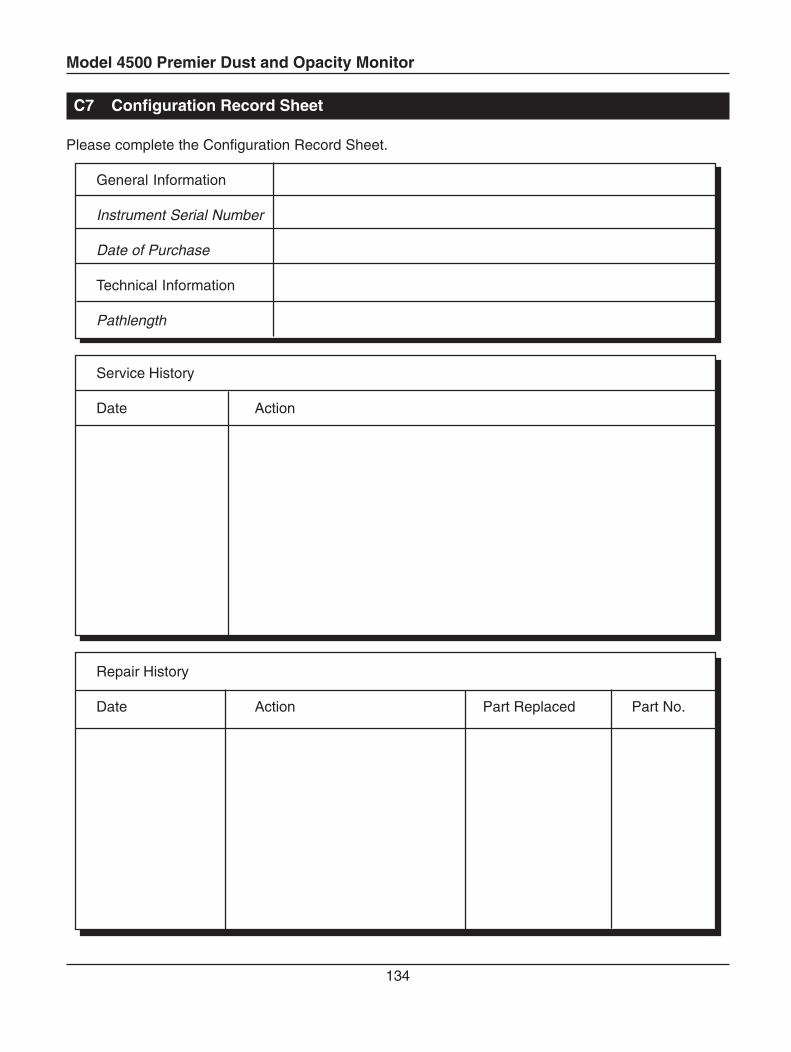
Model 4500 Premier Dust and Opacity Monitor
134
C7 Configuration Record Sheet
Please complete the Configuration Record Sheet.
General Information
Instrument Serial Number
Date of Purchase
Technical Information
Pathlength
Service History
Date Action
Repair History
Date Action Part Replaced Part No.

Model 4500 PremierDust / Opacity Monitor
(Appendix)Part No 770.084

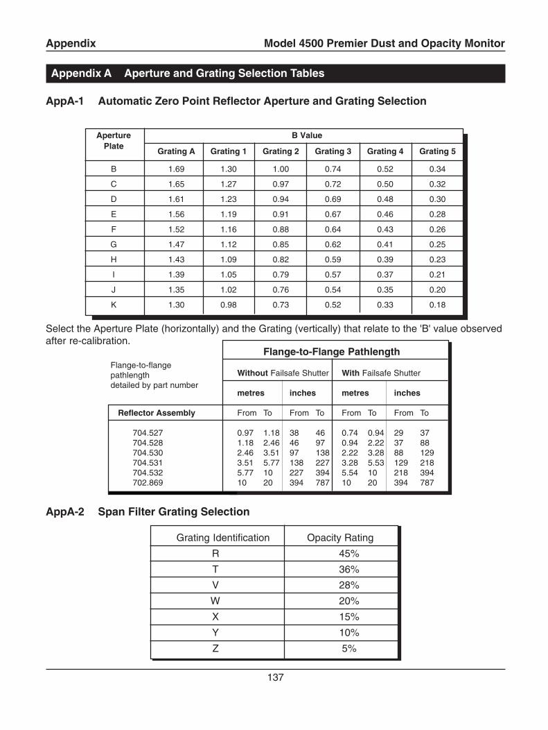
Appendix Model 4500 Premier Dust and Opacity Monitor
137
Appendix A Aperture and Grating Selection Tables
AppA-1 Automatic Zero Point Reflector Aperture and Grating Selection
Aperture B ValuePlate
Grating A Grating 1 Grating 2 Grating 3 Grating 4 Grating 5
B 1.69 1.30 1.00 0.74 0.52 0.34
C 1.65 1.27 0.97 0.72 0.50 0.32
D 1.61 1.23 0.94 0.69 0.48 0.30
E 1.56 1.19 0.91 0.67 0.46 0.28
F 1.52 1.16 0.88 0.64 0.43 0.26
G 1.47 1.12 0.85 0.62 0.41 0.25
H 1.43 1.09 0.82 0.59 0.39 0.23
I 1.39 1.05 0.79 0.57 0.37 0.21
J 1.35 1.02 0.76 0.54 0.35 0.20
K 1.30 0.98 0.73 0.52 0.33 0.18
Select the Aperture Plate (horizontally) and the Grating (vertically) that relate to the 'B' value observedafter re-calibration.
AppA-2 Span Filter Grating Selection
Grating Identification Opacity Rating
R 45%
T 36%
V 28%
W 20%
X 15%
Y 10%
Z 5%
Flange-to-Flange Pathlength
Without Failsafe Shutter With Failsafe Shutter
metres inches metres inches
Reflector Assembly From To From To From To From To
704.527 0.97 1.18 38 46 0.74 0.94 29 37704.528 1.18 2.46 46 97 0.94 2.22 37 88704.530 2.46 3.51 97 138 2.22 3.28 88 129704.531 3.51 5.77 138 227 3.28 5.53 129 218704.532 5.77 10 227 394 5.54 10 218 394702.869 10 20 394 787 10 20 394 787
Flange-to-flangepathlengthdetailed by part number
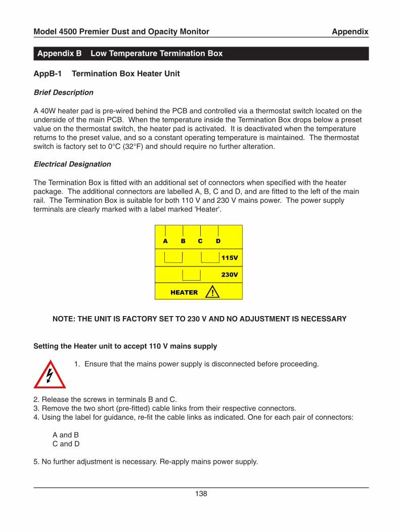
Model 4500 Premier Dust and Opacity Monitor Appendix
138
Appendix B Low Temperature Termination Box
AppB-1 Termination Box Heater Unit
Brief Description
A 40W heater pad is pre-wired behind the PCB and controlled via a thermostat switch located on theunderside of the main PCB. When the temperature inside the Termination Box drops below a presetvalue on the thermostat switch, the heater pad is activated. It is deactivated when the temperaturereturns to the preset value, and so a constant operating temperature is maintained. The thermostatswitch is factory set to 0°C (32°F) and should require no further alteration.
Electrical Designation
The Termination Box is fitted with an additional set of connectors when specified with the heaterpackage. The additional connectors are labelled A, B, C and D, and are fitted to the left of the mainrail. The Termination Box is suitable for both 110 V and 230 V mains power. The power supplyterminals are clearly marked with a label marked 'Heater'.
NOTE: THE UNIT IS FACTORY SET TO 230 V AND NO ADJUSTMENT IS NECESSARY
Setting the Heater unit to accept 110 V mains supply
1. Ensure that the mains power supply is disconnected before proceeding.
2. Release the screws in terminals B and C.3. Remove the two short (pre-fitted) cable links from their respective connectors.4. Using the label for guidance, re-fit the cable links as indicated. One for each pair of connectors:
A and BC and D
5. No further adjustment is necessary. Re-apply mains power supply.
1.1 Thermostatically Controlled Heated Local Control Unit
!"#
!
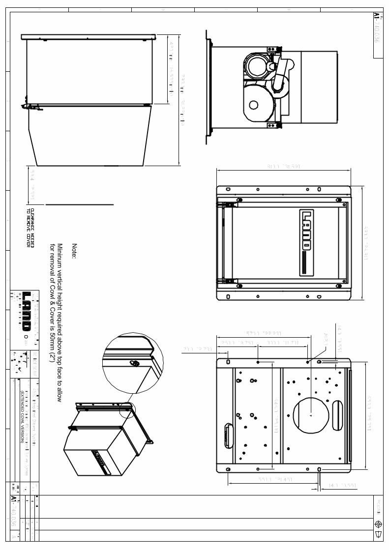
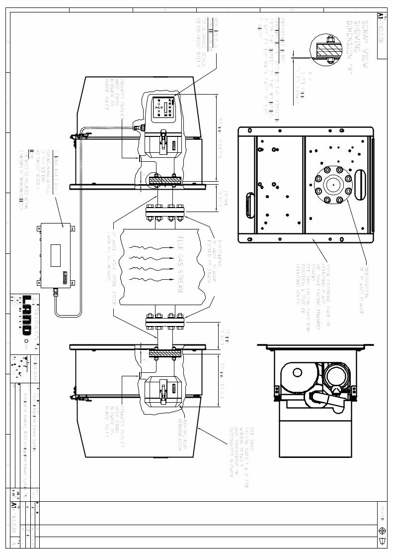
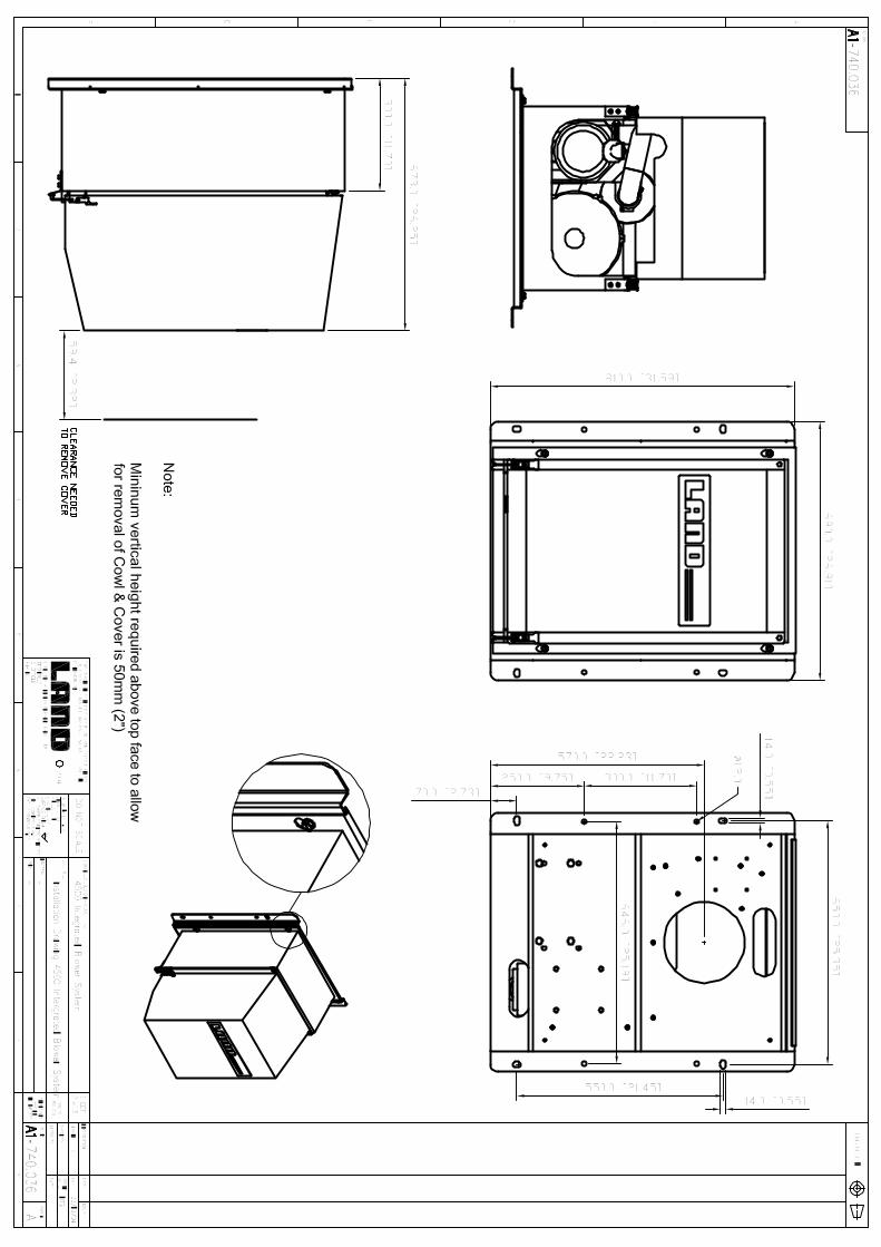
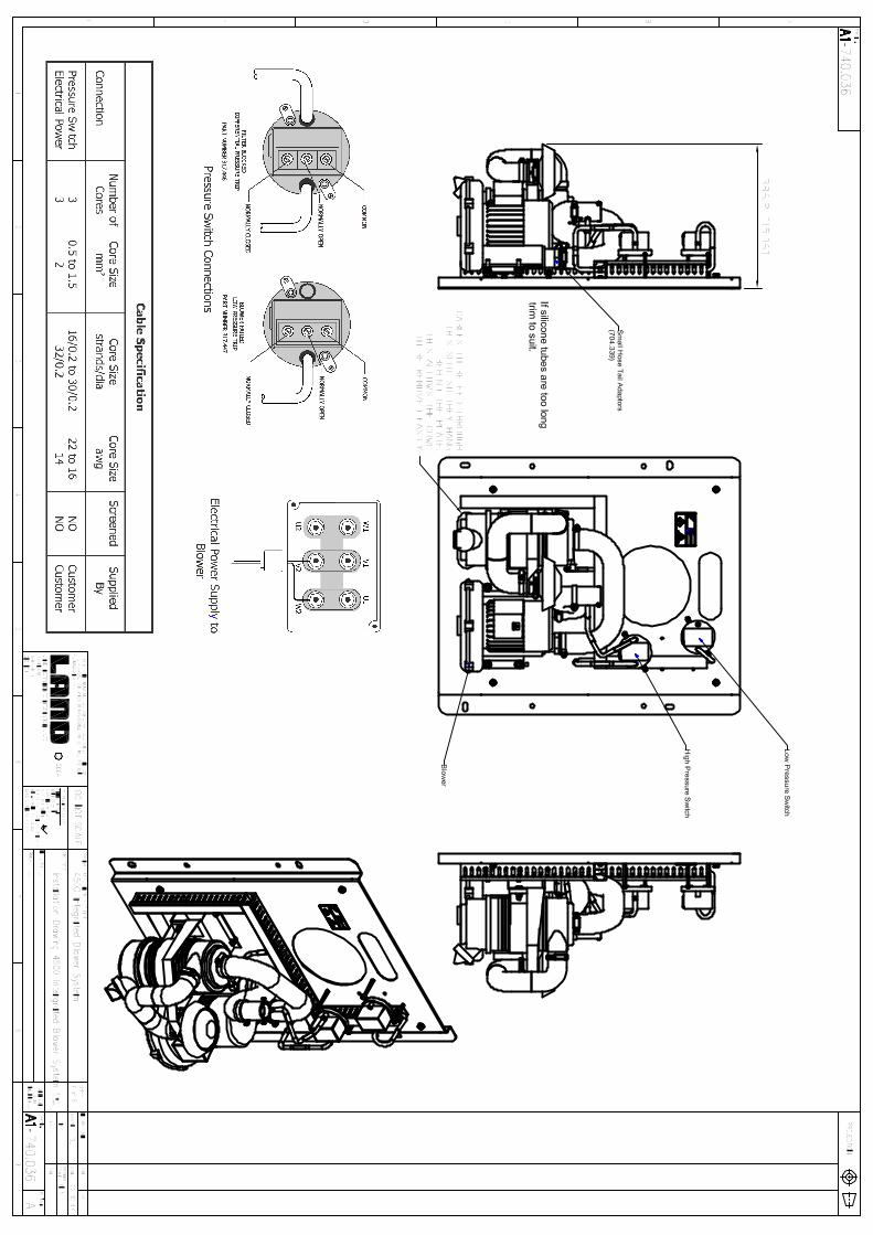
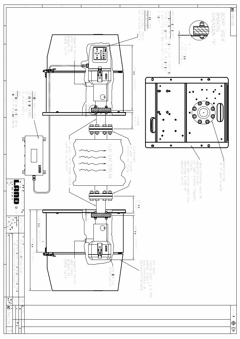

Rev 3 May 2011
Gas Monitoring Products
Standard Terms of Warranty
Land Instruments International warrant all products of our own manufacture to be within specified limits of calibration,if any, when despatched from our works. Also that they are free from defects in material and workmanship fornormal use and service when used for their intended purpose within the limits of our specification. The period ofwarranty, with respect to defects in material and workmanship, will be one year from date of despatch, or readinessfor despatch should delivery be delayed by the customer who has been notified of the readiness at or after theacknowledged estimated date of despatch.
Land Instruments International guarantees to repair any defective workmanship or replace at its own option anydefective parts in any product of its manufacture, provided that the defective instrument is returned to our worksfree of charge and securely packed. Also, provided that the said goods are found to be solely defective due to faultydesign, materials or workmanship and not by improper use or accident.
Items which under their normal course of use or storage, age or deteriorate e.g. measuring cells, batteries, vacuumtubes, thermocouples, are not covered by this warranty, and will be charged for if replaced together with labourcharges for any work found not to be covered by the warranty and any transport or import charges incurred by LandInstruments International at the customers expense.
Equipment or components purchased by Land Instruments International from other manufacturers and used with orwithin Land Instruments International equipment bear only the warranty of the original manufacturer.Warranty work will only be carried out on site on receipt of an official order from the customer who will be chargedfor all travelling time plus travelling and living expenses involved to carry out the work. Should the said faulty opera-tion not be the cause of the instrument’s faulty design, materials or workmanship, but due to application conditions,Land Instruments International reserve the right to charge additionally for all labour on establishing this atthe customer’s works.
Warranty cover is subject to the correct planned maintenance being done in accordance with the published serviceschedule. Failure to follow the planned maintenance will void the warranty terms. Any warranty claim in this eventwill be at the discretion of Land Instruments International.Whilst every care is taken in the manufacture of our products, we can accept no responsibility for any consequentialloss, however caused, through the failure of any of our products to operate accurately or correctly.
All products except 4500mkIIIThe standard warranty on new instruments is a 1-year return-to-base warranty, including all electrochemical cells.. Ifrepairs are performed at site, then travelling time and expenses will be charged at standard rates. Purchased SpareParts are warranted for 1 year from date of shipment, carriage included. If a Spare Part is supplied under warranty,then this part is only warranted for the residue of the applicable warranty period. Calibration filters are not warrantedagainst any damage or change in characteristic that may occur due to mishandling.
Model 4500mkIIIThe standard warranty on new instruments is a 3-year return-to-base warranty. If repairs are performed at site, thentravelling time and expenses will be charged at standard rates. Purchased Spare Parts are warranted for 1 year fromdate of shipment, carriage included. If a Spare Part is supplied under warranty, then this part is only warranted forthe residue of the applicable warranty period. Calibration filters are not warranted against any damage or change incharacteristic that may occur due to mishandling. The 4500mkIII light source has a lifetime warranty.
Exclusions1. Warranty subject to the analysers being used in the manner for which they were designed2. Warranty subject to all recommended maintenance being performed as defined in the operatingor service manual or in the quotation3. The following consumable items are specifically excluded: All filters, Chemical filters, ChemicalDrying Agents, Batteries.