Embed Size (px)
Citation preview

Instruction Manual 748023-X November 2002
http://www.processanalytic.com
Model 400A Hydrocarbon Analyzer
NOTE: This manual is applicable to Model 400A, Catalog Number 194104 with
Serial Numbers beginning with 1999999.

Emerson Process Management Rosemount Analytical Inc. Process Analytic Division 1201 N. Main St. Orrville, OH 44667-0901 T (330) 682-9010 F (330) 684-4434 e-mail: [email protected] http://www.processanalytic.com
ESSENTIAL INSTRUCTIONS READ THIS PAGE BEFORE PROCEEDING!
Rosemount Analytical designs, manufactures and tests its products to meet many national and international standards. Because these instruments are sophisticated technical products, you MUST properly install, use, and maintain them to ensure they continue to operate within their normal specifications. The following instructions MUST be adhered to and integrated into your safety program when installing, using, and maintaining Rosemount Analytical products. Failure to follow the proper instructions may cause any one of the following situations to occur: Loss of life; personal injury; property damage; damage to this instrument; and warranty invalidation.
• Read all instructions prior to installing, operating, and servicing the product.
• If you do not understand any of the instructions, contact your Rosemount Analytical representative for clarification.
• Follow all warnings, cautions, and instructions marked on and supplied with the product.
• Inform and educate your personnel in the proper installation, operation, and maintenance of the product.
• Install your equipment as specified in the Installation Instructions of the appropriate Instruction Manual and per applicable local and national codes. Connect all products to the proper electrical and pressure sources.
• To ensure proper performance, use qualified personnel to install, operate, update, program, and maintain the product.
• When replacement parts are required, ensure that qualified people use replacement parts specified by Rosemount. Unauthorized parts and procedures can affect the product’s performance, place the safe operation of your process at risk, and VOID YOUR WARRANTY. Look-alike substitutions may result in fire, electrical hazards, or improper operation.
• Ensure that all equipment doors are closed and protective covers are in place, except when maintenance is being performed by qualified persons, to prevent electrical shock and personal injury.
The information contained in this document is subject to change without notice.
Teflon is a Registered Trademark of E.I. duPont de Nemours and Co., Inc. SNOOP is a registered trademark of NUPRO Co.

Instruction Manual 748023-X
November 2002
Rosemount Analytical Inc. A Division of Emerson Process Management Contents i
Model 400A
TABLE OF CONTENTS
PREFACE...........................................................................................................................................P-1 Definitions ...........................................................................................................................................P-1 Safety Summary .................................................................................................................................P-2 General Precautions For Handling And Storing High Pressure Gas Cylinders .................................P-4 Documentation....................................................................................................................................P-5
1-0 DESCRIPTION AND SPECIFICATIONS..............................................................................1-1 1-1 Analyzer Mounting Options ...................................................................................................1-1 1-2 Fuel Gas Options...................................................................................................................1-1 1-3 Output Options ......................................................................................................................1-2 1-4 Sample Pump Option ............................................................................................................1-3 1-5 Gas Safety Features..............................................................................................................1-3 1-6 Specifications.........................................................................................................................1-4
2-0 INSTALLATION ....................................................................................................................2-1 2-1 Facility Preparation................................................................................................................2-1
a. Location...........................................................................................................................2-1 b. Utility Specifications ........................................................................................................2-1
2-2 Fuel and Air Requirements....................................................................................................2-1 a. Fuel Gas..........................................................................................................................2-1 b. Air ....................................................................................................................................2-2
2-3 Sample Handling ...................................................................................................................2-2 2-4 Gas Connection and Leak Check Procedure........................................................................2-2 2-5 Electrical Connections ...........................................................................................................2-4
a. Power Connection...........................................................................................................2-4 b. Voltage Output Selection and Cable Connections for Recorder ....................................2-5 c. Optional Voltage to Current Output Board (P/N 620433) ...............................................2-5 d. Auxiliary Contacts ...........................................................................................................2-6 e. Remote Range Control and Indication............................................................................2-6 f. Sample Pump Accessory (P/N 621062) .........................................................................2-7
3-0 STARTUP AND CALIBRATION...........................................................................................3-1 3-1 Initial Startup and Calibration ................................................................................................3-1
a. Selection of Calibration Method and Assoicated Gas(es) ..............................................3-4 3-2 Calibration Procedure............................................................................................................3-5 3-3 Range Switch ........................................................................................................................3-6
4-0 OPERATION .........................................................................................................................4-1 4-1 Routine Operation .................................................................................................................4-1 4-2 Recommended Calibration Frequency..................................................................................4-1 4-3 Shutdown...............................................................................................................................4-1 4-4 Obtaining Maximum Sensitivity .............................................................................................4-1

Instruction Manual 748023-X November 2002
ii Contents Rosemount Analytical Inc. A Division of Emerson Process Management
Model 400A
5-0 THEORY................................................................................................................................5-1 5-1 Principles of Operation ..........................................................................................................5-1 5-2 Burner ....................................................................................................................................5-1 5-3 Analyzer flow system.............................................................................................................5-2 5-4 Preamplifier Board Assembly P/N 620423 ............................................................................5-2 5-5 Main Electronics Board Assembly P/N 620428.....................................................................5-3
a. Post Amplifier ..................................................................................................................5-3 b. Digital Display .................................................................................................................5-3 c. Span................................................................................................................................5-3 d. Output Circuits ................................................................................................................5-3 e. Voltage Current Output Option, P/N 620438 ..................................................................5-3 f. Remote Range Control ...................................................................................................5-4
5-6 Temperature Control Board Assembly P/N 620446..............................................................5-4 a. Temperature Controller ...................................................................................................5-4 b. Heater Assembly.............................................................................................................5-4
5-7 Ignition Circuit ........................................................................................................................5-4 5-8 System Power Supplies.........................................................................................................5-5
6-0 SERVICE AND TROUBLESHOOTING ................................................................................6-1 6-1 System Checkout ..................................................................................................................6-1
a. Amplifier Zero Adjustment...............................................................................................6-1 b. Zero Current Adjustment.................................................................................................6-1 c. Electrical Leakage Check ...............................................................................................6-1 d. Flame Ignition..................................................................................................................6-1 e. Noise Check....................................................................................................................6-1 f. Overall Sensitivity Check ................................................................................................6-1 g. Stability Check ................................................................................................................6-2
6-2 Servicing Flow System and Burner .......................................................................................6-2 a. Burner Disassembly and Cleaning..................................................................................6-2 b. Thermistor .......................................................................................................................6-3 c. Fuel and Air Restrictors ..................................................................................................6-4 d. Sample Capillary .............................................................................................................6-4
6-3 Troubleshooting.....................................................................................................................6-5
7-0 REPLACEMENT PARTS......................................................................................................7-1 7-1 Circuit Board Replacement Policy.........................................................................................7-1 7-2 Recommended Replacement Parts List................................................................................7-1
8-0 RETURN OF MATERIAL......................................................................................................8-1 8-1 Return Of Material .................................................................................................................8-1 8-2 Customer Service ..................................................................................................................8-1 8-3 Training..................................................................................................................................8-1

Instruction Manual 748023-X
November 2002
Rosemount Analytical Inc. A Division of Emerson Process Management Contents iii
Model 400A
LIST OF ILLUSTRATIONS
Figure 2-1. Range Input-Output Board..................................................................................... 2-5 Figure 3-1. Power Switch Location .......................................................................................... 3-2 Figure 3-2. Typical Curves of Downscale Response vs. Time for Various Hydrocarbons ...... 3-3 Figure 3-3. Example 1 Display ................................................................................................. 3-6 Figure 3-4. Example 2 Display ................................................................................................. 3-7 Figure 3-5. Example 3 Display ................................................................................................. 3-7 Figure 4-1. Typical Curve of Analyzer Response vs. Pressure Setting on Sample Pressure . 4-2 Figure 4-2. Typical Curves of Analyzer Response vs. Pressure Setting on Fuel Pressure
Regulator ............................................................................................................... 4-2 Figure 4-3. Typical Curves of Analyzer Response vs. Pressure Setting on Air Pressure
Regulator ............................................................................................................... 4-3 Figure 5-1. Flame Ionization Detection Theory........................................................................ 5-1 Figure 6-1. Effect of Analyzer Temperature on Background Signal – Typical Curve .............. 6-2
LIST OF TABLES
Table 1-1. Fuel Gas vs. Analyzer Characteristics................................................................... 1-3 Table 2-1. Range Control........................................................................................................ 2-6 Table 3-1. Internal Pressure Regulators – Fuel Gas Settings ................................................ 3-1 Table 3-2. Range Switch Settings........................................................................................... 3-6 Table 5-1. Input Sensitivities................................................................................................... 5-3 Table 5-2. Fullscale Sensitivity ............................................................................................... 5-4
LIST OF DRAWINGS
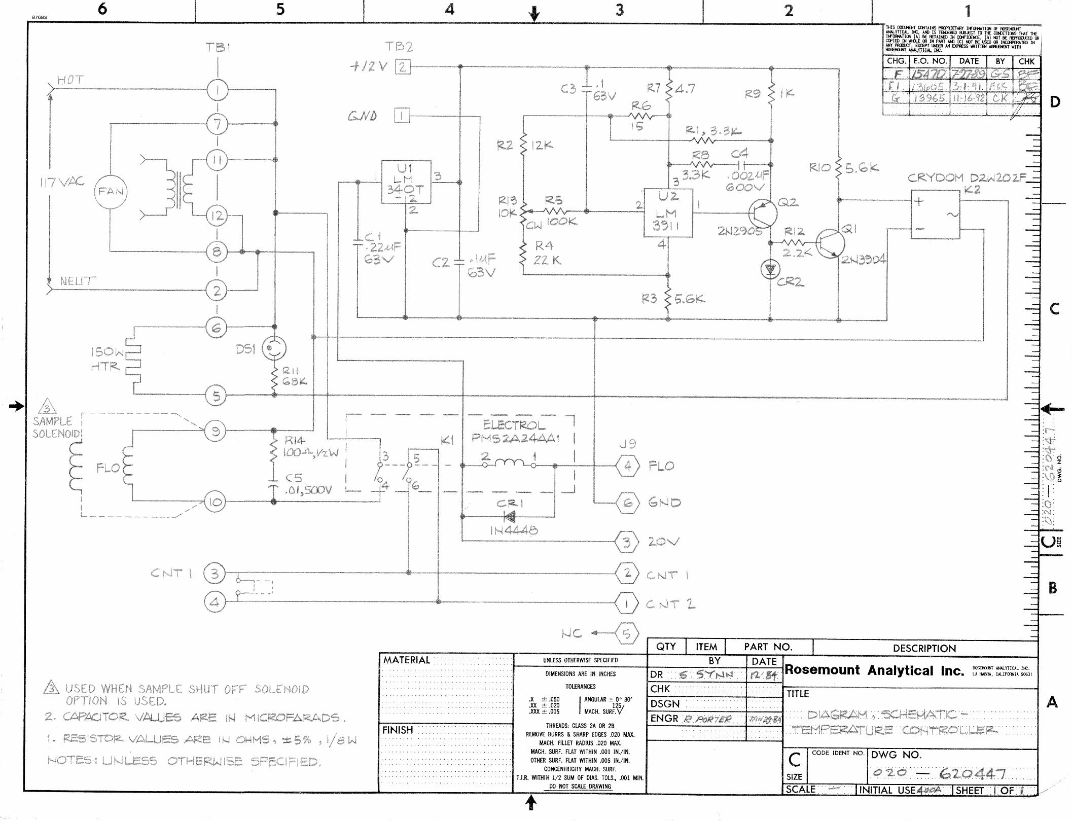
620424 Schematic Diagram, Preamplifier 620429 Schematic Diagram, Main Electronics 620434 Schematic Diagram, Isolated V/I 620439 Schematic Diagram, Isolated Digital Control 620447 Schematic Diagram, Temperature Controller 621072 Pictorial Wiring Diagram, Model 400A 621073 Installation Drawing, Model 400A 622883 Flow Diagram, Model 400A 623190 Burner Parts List

Instruction Manual 748023-X November 2002
iv Contents Rosemount Analytical Inc. A Division of Emerson Process Management
Model 400A

Instruction Manual 748023-X
November 2002
Rosemount Analytical Inc. A Division of Emerson Process Management Preface P-1
Model 400A
PREFACE
The purpose of this manual is to provide information concerning the components, functions, installation and maintenance of the 400A.
Some sections may describe equipment not used in your configuration. The user should become thoroughly familiar with the operation of this module before operating it. Read this instruction manual completely.
DEFINITIONS
The following definitions apply to DANGERS, WARNINGS, CAUTIONS and NOTES found throughout this publication.
DANGER .
Highlights the presence of a hazard which will cause severe personal injury, death, or substantial property damage if the warning is ignored.
WARNING .
Highlights an operation or maintenance procedure, practice, condition, statement, etc. If not strictly observed, could result in injury, death, or long-term health hazards of personnel.
CAUTION.
Highlights an operation or maintenance procedure, practice, condition, statement, etc. If not strictly observed, could result in damage to or destruction of equipment, or loss of effectiveness.
NOTE
Highlights an essential operating procedure, condition or statement.

Instruction Manual 748023-X November 2002
P-2 Preface Rosemount Analytical Inc. A Division of Emerson Process Management
Model 400A
SAFETY SUMMARY
To avoid explosion, loss of life, personal injury and damage to this equipment and on-site property, all personnel authorized to install, operate and service the Model 400A Hydrocarbon Analyzer should be thoroughly familiar with and strictly follow the instructions in this manual. Save these instructions.
AUTHORIZED PERSONNEL
To avoid explosion, loss of life, personal injury and damage to this equipment and on-site property, all personnel authorized to install, operate and service the this equipment should be thoroughly familiar with and strictly follow the instructions in this manual. SAVE THESE INSTRUCTIONS.
DANGER.
ELECTRICAL SHOCK HAZARD
Do not operate without doors and covers secure. Servicing requires access to live parts which can cause death or serious injury. Refer servicing to qualified personnel.
For safety and proper performance, this instrument must be connected to a properly grounded three-wire source of power.
WARNING.
PARTS INTEGRITY
Tampering or unauthorized substitution of components may adversely affect safety of this product. Use only factory documented components for repair.
WARNING.
POSSIBLE EXPLOSION HAZARD
Protection against explosion depends upon special fuel flow limiting restrictor in fuel inlet fitting. Do not remove fuel inlet restrictor. Replace only with factory supplied fitting.

Instruction Manual 748023-X
November 2002
Rosemount Analytical Inc. A Division of Emerson Process Management Preface P-3
Model 400A
WARNING .
POSSIBLE EXPLOSION HAZARD
Do not apply power to analyzer or ignite burner until all leak checks have been performed and until the environment of the analyzer has been determined to be non-hazardous. See Section 2-4 on page 2-2 for leak check procedure.
This instrument uses a fuel containment hydrogen. The instrument is designed to protect against the formation of an explosive gas mixture within the enclosure. It must NOT be operated if the in-ternal ventilation fan is not functioning. Do NOT operate without factory installed fuel flow restric-tor in place.
Check the fuel supply and containment system for leaks, both inside and outside the analyzer, upon installation, before initial startup, during routine maintenance, or any time the integrity of the fuel containment system is broken, to assure that the system is leak-tight.
In the event that flammable sample is to be introduced into this analyzer, it must be equipped with the accessory kit, PN 624080, which restricts sample flow and provides automatic sample shut-off in the event of burner flame-out. Do not operate without sample flow restrictor in place. The sam-ple containment system should also be thoroughly leak checked. This kit is designed considering application on hydrogen sample (LEL+4% v/v). The instrument must not be used on a sample hav-ing a LEL of less than 4% in air.
This analyzer is designed for use in unclassified (general purpose) environments that do not con-tain flammable (explosive) materials. It should be installed in an unconfined, ventilated space.
CAUTION .
HIGH PRESSURE GAS CYLINDERS
For safety and proper performance this instrument must be connected to a properly grounded three-wire source of power.
This analyzer requires periodic calibration with known zero and standard gases. See General Pre-cautions for Handling and Storing High Pressure Cylinders on page 4.

Instruction Manual 748023-X November 2002
P-4 Preface Rosemount Analytical Inc. A Division of Emerson Process Management
Model 400A
GENERAL PRECAUTIONS FOR HANDLING AND STORING HIGH PRESSURE GAS CYLINDERS
Edited from selected paragraphs of the Compressed Gas Association's "Handbook of Compressed Gases" published in 1981
Compressed Gas Association 1235 Jefferson Davis Highway Arlington, Virginia 22202
Used by Permission
1. Never drop cylinders or permit them to strike each other violently.
2. Cylinders may be stored in the open, but in such cases, should be protected against extremes of weather and, to prevent rusting, from the dampness of the ground. Cylinders should be stored in the shade when located in areas where extreme temperatures are prevalent.
3. The valve protection cap should be left on each cylinder until it has been secured against a wall or bench, or placed in a cylinder stand, and is ready to be used.
4. Avoid dragging, rolling, or sliding cylinders, even for a short distance; they should be moved by using a suitable hand-truck.
5. Never tamper with safety devices in valves or cylinders.
6. Do not store full and empty cylinders together. Serious suckback can occur when an empty cylinder is attached to a pressurized system.
7. No part of cylinder should be subjected to a temperature higher than 125°F (52°C). A flame should never be permitted to come in contact with any part of a compressed gas cylinder.
8. Do not place cylinders where they may become part of an electric circuit. When electric arc welding, precautions must be taken to prevent striking an arc against the cylinder.

Instruction Manual 748023-X
November 2002
Rosemount Analytical Inc. A Division of Emerson Process Management Preface P-5
Model 400A
DOCUMENTATION
The following Model 400A instruction materials are available. Contact Customer Service Center or the local representative to order.
748023 Instruction Manual (this document)
Instruction Manual 748023-X November 2002
P-6 Preface Rosemount Analytical Inc. A Division of Emerson Process Management
Model 400A

Instruction Manual 748023-X
November 2002
Rosemount Analytical Inc. A Division of Emerson Process Management Description and Specifications 1-1
Model 400A
SECTION 1 DESCRIPTION AND SPECIFICATIONS
The Model 400A Hydrocarbon Analyzer automatically and continuously measures the concentration of hydrocarbons in a gas stream. Typical applications include monitor-ing atmospheric air for low-level hydrocarbon contaminants and determining the hydrocar-bon content of exhaust emissions from inter-nal combustion engines.
The analyzer utilizes the flame ionization method of detection. The sensor is a burner in which a regulated flow of sample gas passes through a flame sustained by regulated flows of a fuel gas and air. Within the flame, the hy-drocarbon components of the sample stream undergo a complex ionization that produces electrons and positive ions. Polarized elec-trodes collect these ions, causing current to flow through an electronic measuring circuit. The ionization current is proportional to the rate at which carbon atoms enter the burner, and is therefore a measure of the concentra-tion of hydrocarbons in the original sample. The analyzer provides readout on a front-panel digital display and a selectable output for an accessory recorder.
To ensure stable, drift-free operation, particu-larly in high-sensitivity applications, an internal temperature controller maintains the analyzer interior at a constant 48°C. This feature mini-mizes temperature dependent variations in (a) electronic current-measuring circuitry, and (b) adsorption/desorption equilibrium of back-ground hydrocarbons within the internal flow system.
To minimize system response time, an inter-nal sample-bypass feature provides high ve-locity sample flow through the analyzer.
The Model 400A may be equipped with vari-ous optional features in addition to, or instead of, the standard features of the basic instru-ment. The following paragraphs provide brief descriptions of the principal standard and op-tional features.
1-1 ANALYZER MOUNTING OPTIONS
WARNING
INSTALLATION
For safety, the analyzer should be installed in a non-confined, ventilated space.
The standard analyzer is housed in a case designed for bench-top use, or if desired, the analyzer may be mounted in a cabinet or rack using RETMA spaced mounting holes. Outline dimensions are shown on drawing 621073.
1-2 FUEL GAS OPTIONS For burner fuel gas, the standard analyzer re-quires 40% hydrogen/60% nitrogen or helium. Through installation of the optional 400A hy-drogen fuel kit (P/N 622576), the analyzer may be converted to use 100% hydrogen. This kit may be ordered as a factory installed option or supplied as an option for installation by the user.
The preferred type of fuel depends on the par-ticular application and the characteristics of the sample gas:
1. For measuring low-level hydrocarbons in ambient air, or in other sample gas with relatively constant oxygen content, 100% hydrogen is preferable. It provides the highest obtainable sensitivity and the maximum stability. Zero drift caused by ambient temperature variations of the fuel cylinder is some what lower for 100% hy-drogen than for mixed fuel. (With either fuel, it is desirable to maintain cylinder temperature constant.)
2. For monitoring vehicular exhaust emis-sions, or other sample gas with varying oxygen content, mixed fuel is preferable; and a hydrogen/helium mixture is more desirable than a hydrogen/nitrogen mix-
Instruction Manual 748023-X November 2002
1-2 Description and Specifications Rosemount Analytical Inc. A Division of Emerson Process Management
Model 400A
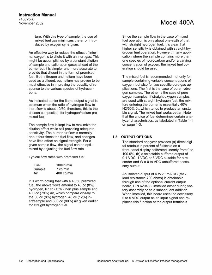
ture. With this type of sample, the use of mixed fuel gas minimizes the error intro-duced by oxygen synergism.
An effective way to reduce the effect of inter-nal oxygen is to dilute it with an inert gas. This might be accomplished by a constant dilution of sample and calibration gases ahead of the burner but it is simpler and more accurate to provide that diluent in the form of premixed fuel. Both nitrogen and helium have been used as a diluent, but helium has proven to be most effective in improving the equality of re-sponse to the various species of hydrocar-bons.
As indicated earlier the flame output signal is optimum when the ratio of hydrogen flow to inert flow is about 40/60; therefore, this is the chosen composition for hydrogen/helium pre-mixed fuel.
The sample flow is kept low to maximize the dilution effect while still providing adequate sensitivity. The burner air flow is normally about four times the fuel flow, and changes have little effect on signal strength. For a given sample flow, the signal can be opti-mized by adjusting the fuel flow rate.
Typical flow rates with premixed fuel:
Fuel 100cc/min Sample 7 cc/min Air 400 cc/min
It is worth noting that with a 40/60 premixed fuel, the above flows amount to 40 cc (8%) hydrogen, 67 cc (13%) inert plus sample and 400 cc (79%) air, which compare closely to the 30 cc (8%) hydrogen, 45 cc (12%) in-ert/sample and 300 cc (80%) air given earlier for straight hydrogen fuel.
Since the sample flow in the case of mixed fuel operation is only about one-sixth of that with straight hydrogen fuel, it is clear that higher sensitivity is obtained with straight hy-drogen fuel operation. However, in any appli-cation where the sample contains more than one species of hydrocarbon and/or a varying concentration of oxygen, the mixed fuel op-eration should be used.
The mixed fuel is recommended, not only for sample containing variable concentrations of oxygen, but also for two specific pure gas ap-plications. The first is the case of pure hydro-gen samples. The other is the case of pure oxygen samples. If straight oxygen samples are used with straight hydrogen fuel, the mix-ture entering the burner is essentially 40% H2/60% 02, which tends to produce an unsta-ble signal. The mixed fuel works better. Note that the choice of fuel determines certain ana-lyzer characteristics, as tabulated in Table 1-1 on page 1-3.
1-3 OUTPUT OPTIONS The standard analyzer provides (a) direct digi-tal readout in percent of fullscale on a front-panel display calibrated linearly from 0 to 100.0%, (b) a selectable buffered output of 0.1 VDC, 1 VDC or 5 VDC suitable for a re-corder and W a 0 to VDC unbuffered acces-sory output.
An isolated output of 4 to 20 mA DC (max. load resistance 700 ohms) is obtainable through use of the optional current output board, P/N 620433, installed either during fac-tory assembly or as a subsequent addition. When installed, this board uses the accessory 0 to 5 VDC output as an input signal and re-places this function at the output terminals.

Instruction Manual 748023-X
November 2002
Rosemount Analytical Inc. A Division of Emerson Process Management Description and Specifications 1-3
Model 400A
ANALYZER CHARACTERISTICS
100% H2 40% H2/60% N2 or 40% H2/He
Fullscale Sensitivity Adjustable from 1 ppm CH4 to 2% CH4 Adjustable from 4 ppm CH4 to 10% CH4
Fuel Consumption 35 to 40 cc/min 75 to 80 cc/min
Operating Range for SAMPLE Pressure Regulator
4 to 5 psig (27 to 34.5 kPa) 1.5 to 5 psig
(10.3 to 34.5 kPa)
Table 1-1. Fuel Gas vs. Analyzer Characteristics
1-4 SAMPLE PUMP OPTION To provide the required sample flow, the sample gas must be under adequate pressure when applied to the analyzer inlet. Refer to Section 2-2a on page 2-1. To permit analysis of gases at atmospheric or sub-atmospheric pressure, the analyzer may be shipped with a sample pump accessory, P/N 621062.
1-5 GAS SAFETY FEATURES The Model 400A is designed to provide a high degree of operational safety. In all analyzers, a front-panel LED indicates that the burner flame is lit. In addition, fuel gas is automati-cally shut off when a flame-out condition oc-curs.
All tubing ahead of the burner is rigid metallic tubing made up with ferrule/nut type compres-sion fittings. However, should there be an in-ternal fuel leak, an inlet fuel flow limiting restrictor, ventilation holes in the enclosure and an internal circulation fan serve to dilute and dissipate the hydrogen fuel for a worst case leak to a safety factor below 25% of the LEL of hydrogen. The design basis for this system presumes 100% hydrogen fuel at 50 psig inlet pressure. 40% hydrogen fuel and
lower inlet pressure serve to further reduce hydrogen concentration in the event of a leak. In reality, an open fitting leak would never oc-cur. As a leak developed the burner would eventually be starved of fuel and flame-out would occur at a leak equivalent of a loss of about 20 psig fuel pressure, thus actuating the fuel shut-off solenoid valve system.
If the sample is flammable, accessory kit P/N 624080, must be utilized. This kit provides a restrictor to limit sample flow and a solenoid valve to shut-off sample in the event of burner flame-out. The design basis for this kit pre-sumes a maximum sample flow rate of 470 cc/min and a sample with LEL not below that of hydrogen (4% v/v in air).
WARNING
POSSIBLE EXPLOSION HAZARD
Protection against explosion depends upon special fuel flow limiting restrictor in fuel inlet fitting. Do not remove fuel inlet restrictor. Replace only with factory sup-plied fitting.

Instruction Manual 748023-X November 2002
1-4 Description and Specifications Rosemount Analytical Inc. A Division of Emerson Process Management
Model 400A
1-6 SPECIFICATIONS Power Requirements..................... 115 VAC ±10%, 50/60 ±3 Hz, 250 W Ambient Temperature.................... 32°F to 110°F (0°C to 43°C) Case Temperature ........................ Controlled at 122°F (50°C) Ambient Humidity .......................... 95% relative humidity, but not in excess of 34°C wet bulb
temperature. Dimensions.................................... 8.75 in (22.2 cm) H
18.75 in. (47.6 cm) W 15.88 in. (39.7 cm) D Recommended panel cutout is 17.75 in. X 8 25 in. (45.1 cm x 21.0 cm). May be mounted in standard 19 inch rack.
Weight ........................................... 22 lbs (10 kg) Repeatability.................................. 1% of fullscale for successive identical samples Response Time ............................. 90% of fullscale in 0.6 seconds with sample bypass flow at 3
liters/minute Analyzer Fullscale Sensitivity
Standard .............................. Adjustable from 4 ppm CH4 to 1% CH4. (Adjustable from 100 ppm CH4 to 10% CH4 using high-range capillary.)
Equipped with 100% Hydrogen Fuel Assembly ..... Adjustable from 1 ppm CH4 to 0.25% CH4
Analyzer Fuel Gas Requirements Standard Analyzer ................ 75 to 80 cc/min premixed fuel consisting of 40% hydrogen and 60%
nitrogen or helium (THC <0.5 ppm) supplied at 45 to 50 psig (309 to 344 kPa) at instrument
Equipped with 100% Hydrogen Fuel Assembly ..... 35 to 40 cc/min of clean, zero grade hydrogen (THC <0.5 ppm) at
45 to 50 psig (309 to 344 kPa) at instrument Sample Gas Requirements
Non-Flammable Samples ..... 0.35 to 3.0 liters/minute at 5 to 10 psig (34 to 69 kPa) Flammable Samples............. 470 cc/minute maximum for safety1
Burner Air Requirements............... 350 to 400 cc/minute of zero grade (THC <1 ppm) air, supplied at 25 to 50 psig (172 to 344 kPa)
Sample Bypass Flow..................... 0.3 to 3.0 liters/minute Stability .......................................... Electronic stability at maximum sensitivity is 1% of fullscale
throughout ambient temperature range of 32°F to 110°F (0°C to 43°C). Built-in temperature controller minimizes effect of ambient temperature variations on internal flow and electronic systems.
Range ............................................ Eight ranges: 1, 2.5, 10, 25, 100, 250, 1000 and REMOTE. In addition SPAN control provides continuously variable adjustment within a dynamic range of 4:1
1 Safety design basis presumes flammable sample having LEL not less than that of hydrogen (4% v/v in air).

Instruction Manual 748023-X
November 2002
Rosemount Analytical Inc. A Division of Emerson Process Management Description and Specifications 1-5
Model 400A
Output............................................ 1) 0 to 5 VDC, 0 to 1 VDC, 0 to 0.1 VDC fully buffered - standard (for 0 to 100.0%).
2) 4 to 20 mA isolated voltage to current - optional (maximum load resistance 700 ohms) 3) 0 to 5 VDC accessory output un-buffered - standard (for 0 to 100.0%) available when current option is not used.
Safety Features ............................. Flame-on indication and automatic flame-out fuel shutoff is standard.
All metal tubing with ferrule/nut compression fittings to minimize po-tential fuel leaks. Self-ventilated system maintains internal atmosphere below 25% of LEL for worst case internal leakage.
Contacts ........................................ Form A contact operates in parallel with flame-out fuel shut-off solenoid contact rating (24 VDC at 1 A) for sample shut-off by use of factory ordered kit (PN 624080) if sample is flammable (hydrogen).
Temperature Control ..................... Setpoint maintained at 122°F (50°C) Data Display .................................. 3-1/2 digit LED, characters 0.52 inches high, range 0000 to 1999 Range Display ............................... 1 digit LED, character 0.52 inches high (1 to 7 normal ranges, 0 to
remote control) Remote Range Control.................. Standard, fully isolated range control and range ID is optional

Instruction Manual 748023-X November 2002
1-6 Description and Specifications Rosemount Analytical Inc. A Division of Emerson Process Management
Model 400A

Instruction Manual 748023-X
November 2002
Rosemount Analytical Inc. A Division of Emerson Process Management Installation 2-1
Model 400A
SECTION 2 INSTALLATION
2-1 FACILITY PREPARATION Sections 2-2a and 2-2b provide information that may be required prior to installation. Re-fer to drawing 621073 for installation dimen-sions.
a. Location Install analyzer in a clean area, not sub-ject to excessive vibration or extreme temperature variations. Preferably, the analyzer should be mounted near the sample stream, to minimize sam-ple-transport time.
WARNING
INSTALLATION RESTRICTIONS
For safety, the analyzer should be installed in a non-confined, ventilated space. Do not block any of the vent holes at the top of each side panel of the instrument as they are part of the safety system.
A thermostatically controlled heating cir-cuit holds internal temperature of the ana-lyzer to the correct operating temperature for ambient temperatures in the range 32°F to 110°F (0°F to 43°C).
The cylinders of fuel, air, and calibration gas(es) should be located in an area of relatively constant ambient temperature.
b. Utility Specifications 115 VAC 10% or 220 VAC 10%, 50/60 Hz, depending on unit specified.
NOTE
220 VAC requires an optional trans-former mounted within the instrument.
2-2 FUEL AND AIR REQUIREMENTS
WARNING
PRESSURIZED GAS
Fuel, air and calibration gas cylinders are under pressure. Mishandling of gas cylin-ders could result in death, injury or prop-erty damage. Handle and store cylinders with extreme caution and in accordance with manufacturer's instructions. Refer to the list of general precautions, which fol-lows Section 7 of this manual.
During normal operation, the analyzer uses fuel and air to maintain the burner flame. Cri-teria for selection of these gases are given in Sections 2-2a and 2-2b. In addition, the ana-lyzer requires suitable standard gas(es) for calibration. Refer to Section 3-1a on page 3-4.
Each gas used should be supplied from a tank or cylinder equipped with a clean, hydrocar-bon-free, two-stage regulator. In addition, a shutoff valve is desirable. Install the gas cylin-ders in an area of relatively constant ambient temperature.
a. Fuel Gas The standard analyzer is equipped to use only mixed fuel, i.e. 40% hydrogen/60% nitrogen or helium. Such blends are sup-plied by many gas vendors specifically for this use, with a guaranteed maximum to-tal hydrocarbon content of 0.5 ppm, measured as methane (THC < 0.5 ppm). This specification should be used when buying such mixtures.
When the analyzer is equipped with the optional hydrogen fuel kit, P/N 622576, 100% hydrogen fuel is to be used. This is also supplied by many gas vendors spe-cifically for this use, with the same guar-anteed total hydrocarbon content (THC <

Instruction Manual 748023-X November 2002
2-2 Installation Rosemount Analytical Inc. A Division of Emerson Process Management
Model 400A
0.5 ppm) which, again, should be speci-fied when buying the gas.
NOTE
Always assure the sample flow is pre-sent when using the 100% hydrogen fuel option. Absence of sample flow can result in burning of detector tip when using 100% hydrogen.
b. Air Burner air should also be relatively free of hydrocarbons in order to assure a low background signal. Several grades of air are supplied by various gas vendors for this use. A maximum total hydrocarbon content of less than 1 ppm (THC < as a zero standard).
An alternate source of pure air for burner and zero gas can be provided by a dia-phragm pump and heated palladium cata-lyst which effectively removes moderate amounts of both hydrocarbons and car-bon monoxide from normal ambient air on a continuous basis.
2-3 SAMPLE HANDLING
CAUTION
BYPASS GAUGE PROTECTION
When applying sample pressures greater than 5 psig, insure that the bypass regula-tor is fully open to protect the bypass gauge.
Operating range for the internal sample pres-sure regulator is 4 to 5 psig (28 to 35 kPa) for an analyzer using 100% hydrogen fuel, and 1.5 to 5 psig (10 to 35 kPa) for an analyzer using mixed fuel. With either fuel, sample and calibration gas(es) must be supplied to the sample inlet at a pressure slightly, but not ex-cessively higher than the desired setting on the internal sample pressure regulator. The criterion for correct supply pressure is that the gas flow discharged from the by-pass outlet must be between 0.5 and 3.0 liters/minute to operate within the control range of the sample
pressure regulator, and preferably should be between 2 and 3 liters/minute to minimize sys-tem response time.
Note that use of excessive bypass flow will not only cause the sample pressure regulator to operate outside its control range, but will also result in rapid depletion of sample and standard gases.
If the analyzer is equipped with the accessory 400A sample pump, P/N 621062, the accept-able pressure range at the pump inlet is ap-proximately -1 to +2.5 psig (7 to 17 kPa). If the pump is used, it will automatically provide a sample bypass flow within the correct range. If the analyzer is not equipped with sample pump, adjustment of the bypass flow is ob-tainable by inserting an external flow control-ler or throttle valve into the external sample line, upstream from the sample inlet. Flow may be measured by connecting a flowmeter to the by-pass outlet.
WARNING
POSSIBLE EXPLOSION ELAZARD
In the event that flammable sample is to be introduced into this analyzer, it must be equipped with the accessory kit P/N 624080, which restricts sample flow and provides automatic sample shut-off in the event of burner flameout. Do not operate without sample flow restrictor in place. The sample containment system should also be thoroughly leak checked. This kit is designed considering application on hydrogen sample (LEL=4% v/v). The in-strument must not be used on a sample having a LEL less than 4% in air.
2-4 GAS CONNECTION AND LEAK CHECK PROCEDURE For external gas lines, the use of all new tub-ing throughout is strongly recommended. Copper refrigeration tubing is preferred. Stainless steel tubing is less desirable, be-cause it contains hydrocarbon contaminants, necessitating thorough cleaning before instal-lation.

Instruction Manual 748023-X
November 2002
Rosemount Analytical Inc. A Division of Emerson Process Management Installation 2-3
Model 400A
In connecting gas supply lines and associated fittings, use Teflon tape only. Do not use pipe thread compound or other substance with an organic base.
DANGER
POSSIBLE EXPLOSION HAZARD
Do not apply power to analyzer or ignite burner until all leak checks have been per-formed and until the environment of the analyzer has been determined to be non-hazardous. See Step 8 for leak check procedure.
This analyzer has been designed for use in environments that do not contain combus-tible or explosive materials.
This analyzer uses a fuel containing hy-drogen. Leakage from the fuel containment system can result in an explosion. The fuel supply and containment system, both in-side and outside the analyzer, should be carefully checked for leaks upon installa-tion, before initial startup, during routine maintenance or any time the integrity of the containment system is broken.
If hazardous sample is to be introduced into this analyzer, the leak check proce-dure should also be applied to the sample containment system, both inside and out-side the analyzer.
Proceed as follows:
1. Check analyzer to make sure that plugs and caps are removed from all inlet and outlet fittings.
2. If a vent line is to be connected to ex-haust outlet, use 1/2-inch ID tube slanted downward at least 10 degrees from horizontal.
NOTE Since water vapor is formed during oxida-tion of hydrogen, burner exhaust gas al-ways contains moisture, even if air and fuel entering the burner are completely dry. Unless exhaust line slants down, wa-
ter may accumulate in line, causing back pressure and noisy readings. If exhaust line becomes blocked, water may back up in line and flood burner.
3. If sample is toxic or noxious, or is to be reclaimed, connect by-pass outlet to suitable disposal system. Do not use any device causing back pressure on burner.
4. Clean external fuel, air, and sample lines and regulators. If necessary, heat lines with torch to drive out contami-nants.
CAUTION
DISCONNECT LINE
Do not perform this operation with the line connected to the analyzer.
Recommended method is to attach the tubing to either a nitrogen or helium cyl-inder through a two-stage regulator, and adjust the regulator for a low flow of gas through the tubing. Use a pro-pane or natural gas torch to heat the tubing to at least 300°C, working the heat source slowly from the regulator end to the open end. This will remove contaminants from the inside walls of the tubing, and drive them out the open end.
5. Connect external fuel and air lines to fuel and air inlet fittings on analyzer. Connect external sample line to sample inlet on analyzer (or to inlet fitting on sample pump, if used).
6. Adjust regulators on fuel and air cylin-ders (or other gas supply sources) for appropriate output pressure. Maximum permissible pressure at AIR and FUEL inlets of analyzer is 50 psig (345 kPa). The pressure at the air inlet must be at least 5 psig (35 kPa) higher than the desired setting on the air pressure gauge within the analyzer. Thus if the internal FUEL pressure regulators are to be set at a typical value of 25 psig

Instruction Manual 748023-X November 2002
2-4 Installation Rosemount Analytical Inc. A Division of Emerson Process Management
Model 400A
(172 kPa), the pressure at the FUEL inlet must be set 15 to 20 pounds higher than the operating pressure.
7. Supply sample gas at appropriate pres-sure, as explained in Section 2-3 on page 2-2. Sample bypass flow must be between 0.5 and 3.0 liters/minute for proper operation. Preferably, it should be between 2.0 and 3.0 liters/minute, to minimize system response time. Flow may be measured by connecting a flowmeter to BY-PASS outlet.
WARNING
EXPLOSION HAZARD
Be particularly careful in checking for leaks in the fuel lines. Fuel gas leakage can cause an explosion.
8. Check all gas connections to ensure that they are leak free. Use of SNOOP (P/N 837801) or other suitable leak-test liquid is recommended. Do not use soap or other organic substances; they will contaminate the system, resulting in excessive noise and background cur-rent. To leak check the fuel contain-ment system, it is necessary to have full operating pressure within the sys-tem. To accomplish this, hold the mo-mentary IGNITE/PURGE switch in the up or PURGE position.
2-5 ELECTRICAL CONNECTIONS
WARNING
PROPER GROUNDING
For proper performance and safety it is imperative that this instrument be con-nected to a properly grounded three-wire outlet.
WARNING
CHECK GAS CONNECTIONS
Before supplying electrical power to ana-lyzer, complete the gas connections and verify that fuel gas connections are leak free. Refer to Section 2-4 on page 2-2.
a. Power Connection The Model 400A is provided with a power cable utilizing a 3-pin receptacle that con-nects directly to an input power selection box on the rear of the instrument. Ex-treme caution must be observed with power selection, since the 400A can op-erate on either 115 VAC, 50/60 Hz or 220 VAC, 50/60 Hz.
115 VAC Operation - Unless otherwise specified, the instrument is supplied for 115 VAC operation. (Note that the power input box and power selection card dis-play 115 VAC operation.) The power ca-ble supplied is provided with a North American style parallel blade grounded plug which must be inserted into a 3 wire grounded receptacle.
220 VAC Operation - When 220 VAC operation is specified the instrument will be shipped suitable for this voltage. If the 220 VAC option is added later, then proper voltage selection must be made by removing and rotating the program card within the power box. The line changing transformer mounts inside the instrument and connects to the main electronics cir-cuit board assembly.

Instruction Manual 748023-X
November 2002
Rosemount Analytical Inc. A Division of Emerson Process Management Installation 2-5
Model 400A
RANGE CONTROL
1 2 3 4 5 6
J8
1 2 3 4 5 6 7 REM 24V 24V
1 2 3 4 5 6 7 8 9 10
RANGE RET
CNT1 CNT2 SND OUT (+) (-)VI
24VDC MAX1 AMP
OUTPUT
b. Voltage Output Selection and Cable Connections for Recorder
The standard analyzer provides voltage output only. As shipped from the factory, the analyzer is set up for use with a 100 mV recorder (program header connecting pins E9 and E10).
A selection of three voltage output ranges, 0 to 0.1 VDC, 0 to 1.0 VDC or 0 to 5.0 VDC are available at terminals 3 and 4 of the lower six-position barrier strip labeled OUTPUT. Refer to Figure 2-1 below. To select 0 to 1.0 VDC range, connect pins E7 and E8 on the main elec-tronics board assembly, P/N 620428, with the program header. For the 0 to 5.0 VDC range, connect pins E5 and E6 and for 0 to 0.1 VDC range, connect pins E9 and E10 with the program header. This is a fully buffered signal and can be used with most types of voltage recorders. A 10 VDC output displays 1999 on digital read-out, indicating 99.9% over-range. A 5 VDC output displays 1000 on digital read-out and indicates 100%, the normal in-strument span.
c. Optional Voltage to Current Output Board (P/N 620433)
The optional current output in the range of 4 to 20 mADC appears at terminals 5 and 6. Refer to Figure 2-1 below. This current may be transformed back to a voltage us-ing the appropriate resistor. This fully iso-lated current board is an instrument option and mounts internally on the Model 400A front panel assembly. The maxi-mum value of load resistor is 700 ohms. The 4 to 20 mA is valid over the range of 0 to 100%; the over-range capability of 99.9% is not usable with this option be-cause maximum output of 20 mA corre-sponds to 5 VDC out.
If the voltage to current option is not util-ized, insert program header connecting pins E1/E2 and E3/E4 on the main elec-tronics board assembly to allow a voltage to appear at terminals 5 and 6 in place of the current.
Figure 2-1. Range Input-Output Board

Instruction Manual 748023-X November 2002
2-6 Installation Rosemount Analytical Inc. A Division of Emerson Process Management
Model 400A
d. Auxiliary Contacts A Form A contact closure is available on pins 1 and 2 of the lower barrier strip at the rear of instrument. Refer to Figure 2-1 on page 2-5. These contacts may be used with an existing alarm panel or annuncia-tor system, providing the current and volt-age limits are observed. The rating for the contacts is 24 V at 1A DC. Contacts op-erate in parallel with the internal fuel shutoff solenoid and may therefore be used for external "flame out" indication.
e. Remote Range Control and Indication The Model 400A allows remote control of range or alternatively remote control indi-cation; this is standard with each unit. As an option, a fully isolated interface may be
installed. It performs the same function but assures electrical isolation between the analyzer and the control or indication module. The isolated range/indication op-tion requires an external 24 VDC power supply for operation.
Range Control (Non-Isolated)
Terminals 1 through 7 on the upper termi-nal block at the rear of the instrument are used for this function. Select RMT on the front panel RANGE switch. Connect the respective line, 1 through 7, to pin 3 (la-beled GND) on the lower barrier strip. The front panel will indicate the range se-lected. Terminals 1 through 7 correspond to ranges 1 through 7. Table 2-1 below shows a simple range selection arrange-ment.
Lower TB Upper TB
Terminal 3 1 2 3 4 5 6 7 Range 1 X X Range 2 X X Range 3 X X Range 4 X X Range 5 X X Range 6 X X Range 7 X X
Table 2-1. Range Control
Range Indication (Non-Isolated)
When the RANGE switch is in any posi-tion, including RMT, the range selection of the instrument may be determined by sensing an output in terminals 1 through 8 on the upper terminal strip at the rear of the instrument. Any selected range, 1 through 7 or RMT (position 8), will be in-dicated as a low or ground signal with re-spect to pin 3 of the lower barrier strip labeled GND; all unselected ranges will
indicate a high or +5 VDC with respect to this same terminal.
Isolated Range Control Option (P/N 620438)
When this option is installed the same terminals 1 through 7 are used for range control or indication; however, +24 V power supply must be connected between terminals 9 and 10 labeled 24 V and 24 V RET respectively. For range control select

Instruction Manual 748023-X
November 2002
Rosemount Analytical Inc. A Division of Emerson Process Management Installation 2-7
Model 400A
RMT and connect the desired range ter-minal 1 through 7 to pin 9 labeled 24 V on the upper terminal strip.
Isolated Range Indication Option (P/N 620438)
For isolated range indication the front panel switch must be in any position other than RMT; the selected range will be indi-cated as a contact closure between any pin 1 through 7 with respect to pin 9 la-beled 24 V.
NOTE
Inappropriate use of these lines when the instrument is not in the remote po-
sition will result in range confusion within the instrument.
f. Sample Pump Accessory (P/N 621062) If a sample pump is used, 115 VAC, 50/60 Hz power must be provided to the pump accessory independently. A power cord is provided with this option and mates with a standard 3-pin power con-nector at the rear of the housing.

Instruction Manual 748023-X November 2002
2-8 Installation Rosemount Analytical Inc. A Division of Emerson Process Management
Model 400A

Instruction Manual 748023-X
November 2002
Rosemount Analytical Inc. A Division of Emerson Process Management Startup and Calibration 3-1
Model 400A
SECTION 3 STARTUP AND CALIBRATION
3-1 INITIAL STARTUP AND CALIBRATION Section 3-1a on page 3-4 discusses calibra-tion methods and the associated standard gases. Section 3-2 on page 3-5 explains the typical calibration procedure.
After installing analyzer per Section 2, pro-ceed as follows:
1. Set the RANGE multiplier switch (located inside the small door on the analyzer front panel) at 1000. Place the POWER switch (located in the upper right corner of the main electronics board on the back of the front panel) at ON. See Figure 3-1 on page 3-2. The display should light up.
2. Set external regulators on air and fuel cyl-inders (or other gas supply sources) for suitable output pressure. Maximum per-missible pressure at AIR and FUEL inlets of analyzer is 50 psig (345 kPa). The pressure at the AIR inlet must be at least 5 psig (25 kPa) higher than the desired setting on the air pressure gauge within the analyzer. The internal FUEL pressure regulator is to be set at a typical value of 25 psig (172 kPa), the pressure at the FUEL inlet must be set at least 20 lbs. higher than the operation pressure.
3. If analyzer uses 100% hydrogen fuel, supply actual sample or other suitable gas to SAMPLE inlet port of analyzer (or to inlet fitting on sample pump, if provided). Note pressure and flow requirements ex-plained in Section 2-4 on page 2-2.
CAUTION
POSSIBLE BURNER DAMAGE
If analyzer uses 100% hydrogen fuel, an adequate flow of sample or other gas must enter sample inlet at all times when flame is burning. Otherwise, burner will overheat and damage burner tip. If analyzer uses mixed fuel, sample flow may be initiated at this time, although it is not necessary.
4. Set internal pressure regulators at values appropriate to the fuel gas used. Refer to Table 3-1 below.
The PURGE/IGNITE switch haws two positions, IGNITE and PURGE.
5. With PURGE/IGNITE switch in PURGE position, wait about one minute for fuel gas to purge flow system. During purging period, rotate FUEL pressure regulator al-ternately clockwise and counterclockwise several times, then return to setting speci-fied in step 4.
6. Briefly hold (2 to 4 seconds) PURGE/IGNITE switch in IGNITE posi-tion, then release. FLAME indicator should now be ON, indicating that flame is burning. If so, proceed with following steps. If FLAME indicator does not stay on, the flame is not burning. Again, actu-ate IGNITE switch.
Fuel Gas Internal Pressure
Regulator 100% H2 Fuel Mixed Fuel Air 5 psig (35 kPa) 5 psig (35 kPa) Fuel 25 psig (175 kPa) 30 psig (207 kPa) Sample 5 psig (35 kPa) 0 psig (0 kPa)
Table 3-1. Internal Pressure Regulators – Fuel Gas Settings

Instruction Manual 748023-X November 2002
3-2 Startup and Calibration Rosemount Analytical Inc. A Division of Emerson Process Management
Model 400A
Figure 3-1. Power Switch Location
If flame does not ignite after several at-tempts, refer to Section 6-3 on page 6-5 Troubleshooting. If difficulty is experi-enced, allowing gas to flow for 20 or 30 seconds in the PURGE position prior to actuating the IGNITE switch may be help-ful.
NOTE If ignition indication [FLAME ON] is ob-served without obtaining proper sensitiv-ity, refer to Section 6-3 on page 6-5, Item 6.
NOTE When lighting the burner after extended shutdown, the instrument will require time to allow fuel to reach the burner. There-fore, extended operation of the switch may be required.
7. Increase setting on internal AIR pressure regulator to at least 15 psig (103 kPa). Recommended operating settings for in-ternal pressure regulators are AIR, 15 psig (103 kPa); FUEL, 25 psig (172 kPa). Verify that FLAME indicator is still on.
The analyzer is equipped with an auto-matic fuel shutoff solenoid. If flame goes out during subsequent operation, fuel gas flow will shut off automatically.
If analyzer has been in regular use, it is now ready for calibration, per Section 3-2 on page 3-5, and then for normal opera-
tion. However, during initial startup, or startup following a prolonged shutdown, the following steps should first be per-formed.
8. Check for contamination in air and fuel systems:
a. Supply a clean, hydrocarbon-free gas, such as pure nitrogen to the SAMPLE inlet. Adjust external flow controller or throttle valve so that flow discharged from BYPASS outlet is between 0.5 and 3.0 liters/minute (preferably be-tween 2.0 and 3.0 liters/minute). Set internal SAMPLE pressure regulator at 5.0 psig (34.5 kPa).
b. Set RANGE switch at 10, SPAN con-trol at 1000 (maximum sensitivity), and ZERO control at 1000 (minimum zero suppression). Approximate fullscale sensitivity is now 10 ppm as methane for mixed fuels if the ana-lyzer uses 100% hydrogen fuel, and 40 ppm methane if the analyzer uses mixed fuel.
c. Check display. Maximum acceptable reading is 50% of fullscale. A higher reading indicates that the contamina-tion level is undesirably high. Exces-sive noise and baseline drift may result, depending on the desired op-erating range. If the instrument is to
OFF ONPOWER
S2
Front Panel
Power Switch S2
Main Electronics Board

Instruction Manual 748023-X
November 2002
Rosemount Analytical Inc. A Division of Emerson Process Management Startup and Calibration 3-3
Model 400A
Sample C6H14 (Hexane)
Sample CH4 (Methane)
Sample C3H8 (Propane)
Analyzer Response
Time
be operated at high sensitivity, the source of the contamination must be determined and the condition cor-rected. The most probable contamina-tion sources are the fuel and air supplies, external regulators and con-necting lines, and the internal flow system of the analyzer.
If the instrument is to be operated at a sensitivity low enough so that the noise and drift will not be observable on the dis-play or recorder, removal of the source of contamination is unnecessary.
9. With flame burning, allow system to stabilize for at least two hours, and preferably for a day. After initial startup, or after startup following a prolonged shutdown, the analyzer may display
baseline drift for a considerable period of time, particularly on the more sensi-tive ranges. Commonly, small amounts of hydrocarbons are present on the in-ner walls of the tubing in both the inter-nal flow system and the external gas-supply system. Drift results from any factor influencing the equilibrium of these absorbed hydrocarbons. Typical causes are change of fuel cylinders or change in temperature or pressure. (Note that this type of drift occurs only when the flame is burning. If drift oc-curs when the flame is extinguished, the electronic circuitry is at fault).
To minimize drift, use clean fuel and air, keep the analyzer clean, and locate the gas cylinders in an area of relatively constant ambient temperature.
Figure 3-2. Typical Curves of Downscale Response vs. Time for Various Hydrocarbons

Instruction Manual 748023-X November 2002
3-4 Startup and Calibration Rosemount Analytical Inc. A Division of Emerson Process Management
Model 400A
a. Selection of Calibration Method and Associated Gas(es)
Preparatory to normal operation of the analyzer, it is necessary to select a suit-able calibration method and appropriate standard gas(es). Proper choice depends on the type of fuel gas, the intended op-erating range, and the desired accuracy. In all methods, the objective is to estab-lish both a downscale point and an up-scale point on the display or recorder chart. Different methods are described below.
Downscale Calibration Point
The downscale calibration point is set with the ZERO control, by the appropriate one of two methods:
1. The generally preferred method is to adjust the ZERO control while a zero standard gas of low, accu-rately-known, hydrocarbon content is entering the SAMPLE inlet port. This method is desirable with all analyzers, and is mandatory if the analyzer utilizes 100% hydrogen fuel. Typically, nitrogen (zero gas grade) is used as the zero gas. If desired, the burner air may be used as zero gas, provided that its hy-drocarbon content is sufficiently low and accurately known. Although ideally the zero gas should be completely hydrocarbon-free, even the most carefully prepared bottled gas contains trace hydrocarbons.. If the analyzer is to be used at high sensitivity, request that the supplier of the zero gas provide an exact determination of its hydrocarbon content.
2. If the analyzer utilizes mixed fuel, an alternative method eliminates the requirement for a special zero gas. Instead, the ZERO control is adjusted with no gas entering the SAMPLE inlet. This method is not possible with analyzer utilizing 100% hydrogen fuel, because the
burner would overheat. Even with mixed fuel, the method is not rec-ommended if the analyzer is to be used at sensitivity less than 100 ppm fullscale.
Refer to Figure 3-2 on page 3-3 for typical curves of downscale response versus time for various hydrocarbons.
Upscale Calibration Point
In all applications, the upscale calibration point is established by adjustment of the SPAN control, while a standard gas of ac-curately known hydrocarbon content is flowing into the SAMPLE inlet port. Since instrument response is linear, it is not necessary that the hydrocarbon content of the span gas fall within the desired oper-ating range. The instrument may be stan-dardized on one range, and then switched to another range without loss of accuracy. Commonly, a conveniently obtained stan-dard such as 100 ppm methane or 1000 ppm methane is used regardless of range.
A span gas consists of a specified con-centration of methane or other hydrocar-bon in a background gas such as nitrogen. Instrument response is affected by the composition of the background gas. Therefore, it is desirable that the span gas contain the same background gas as the actual sample. If so, the back-ground effect is automatically canceled out.
Standard Gas(es)
Upscale standard gas (and zero standard gas, if used) should be supplied from a tank or cylinder equipped with a clean, hydrocarbon free, two-stage pressure regulator.

Instruction Manual 748023-X
November 2002
Rosemount Analytical Inc. A Division of Emerson Process Management Startup and Calibration 3-5
Model 400A
3-2 CALIBRATION PROCEDURE After completing startup procedure of Section 3-1 on page 3-1, calibrate analyzer as ex-plained below.
1. Set downscale calibration point as fol-lows:
a. Supply zero gas to SAMPLE inlet. Adjust external flow controller or throt-tle valve so that flow discharge from BYPASS outlet is between 0.5 and 3.0 liters/minute (preferably between 2.0 and 3.0 liters/minute). Set internal SAMPLE pressure regulator at 5 psig (34 kPa) or other desired value. (Recommended operating range is 4 to 5 psig [28.6 to 34 kPa] for analyzer using 100% hydrogen fuel, and 1.5 to 5 psig [10 to 34 kPa] for analyzer us-ing mixed fuel.)
CAUTION
POSSIBLE BURNER DAMAGE
If analyzer uses 100% hydrogen fuel, an adequate flow of sample or other gas must enter sample inlet at all times when flame is burning. Otherwise, burner will overheat and damage burner tip.
b. Set RANGE switch at 10 and SPAN potentiometer at 1000. The resultant approximate fullscale sensitivity is 10 ppm methane for an analyzer using 100% hydrogen fuel, and 40 ppm methane for an analyzer using mixed fuel.
c. Adjust ZERO control for reading of zero (or appropriate near-zero value) on indicator or recorder. The resultant
setting on the ZERO control is ap-proximately correct, and is sufficiently accurate for most applications. How-ever, if instrument is to be used for high sensitivity analysis, a recheck and possible slight readjustment will be made. Refer to Section 4-4 on page 4-1.
2. Set upscale calibration point as follows:
a. Turn RANGE switch to setting appro-priate to the particular span gas. Re-fer to Table 3-1 on page 3-1.
b. Supply span gas to SAMPLE inlet. Adjust external flow controller or throt-tle valve so that flow discharged from BYPASS outlet is between 0.5 and 3.0 liters/minute (preferably between 2.0 and 3.0 liters/minute). Verify that reading on internal SAMPLE pressure gauge is 5 psig or other desired value; if not, adjust SAMPLE pressure regulator as required.
c. Adjust SPAN control so that the dis-play or recorder gives the desired in-dication. Lock SPAN control by pushing lever down. Analyzer calibra-tion is now sufficiently accurate for most applications. However, if instru-ment is to be used for high sensitivity analysis, recheck zero setting (refer to Section 4-4 on page 4-1). If recorder readout and display do not agree, cor-rect display by adjusting R1 on front panel board.
d. Supply zero gas to SAMPLE inlet as in Step 1a. Set RANGE switch at 10. Note reading on indicator or recorder; if incorrect, adjust ZERO control as required. Lock ZERO control by push-ing lever down. Analyzer is now ready for routine operation as explained in Section 4.

Instruction Manual 748023-X November 2002
3-6 Startup and Calibration Rosemount Analytical Inc. A Division of Emerson Process Management
Model 400A
30.0 2
PERCENT OF RANGE RANGE
RANGE MULTIPLIER
1
2.5
1025 100
250
1000
RMT
Approximate Operating Range SPAN Control At 1000 Range Switch Setting
100 % Hydrogen Fuel Mixed Fuel 1 0 to 1 ppm CH4 0 to 4 ppm CH4 2.5 0 to 2.5 ppm CH4 0 to 10 ppm CH4 10 0 to 10 ppm CH4 0 to 40 ppm CH4 25 0 to 25 ppm CH4 0 to 100 ppm CH4 100 0 to 100 ppm CH4 0 to 400 ppm CH4 250 0 to 250 ppm CH4 0 to 1000 ppm CH4 1000 0 to 1000 ppm CH4 0 to 4000 ppm CH4
NOTE
For best results, calibrate with appropriate span gas every time the range is changed. For a clear understanding of the function of the Range Switch, see Section 3-3 below.
Table 3-2. Range Switch Settings
3-3 RANGE SWITCH The operator can choose from seven range multipliers as represented by the settings on the Range Switch: 1, 2.5, 10, 25, 100, 250, and 1000.
Range I is the most sensitive, range 1000 the least sensitive. Range 1 is 10 times more sensitive than Range 10 and so forth.
The Range Switch settings (multipliers) and the display outputs do not represent hydro-carbon concentrations in percent or ppm. The LED display shows the percent of the fullscale range which has been calibrated on the multi-plier selected. The display also shows which range multiplier has been selected on the Range Switch (1 = 1, 2 = 2.5, 3 = 10, 4 = 25, 5 = 100, etc.).
Range 1 has a maximum sensitivity of 1 ppm CH4 (as 100 % fullscale) if 100 % H2 fuel is used, or 4 ppm CH4 if mixed fuel is used. Range 2.5 has a maximum sensitivity of 2.5 ppm CH4 with 100 % H2, 10.0 ppm CH4 with mixed fuel.
Example 1:
With the Range Switch set at 2.5, the operator can use, for example, 6 ppm CH4 span gas to calibrate the instrument for 20 ppm fullscale (30.0 % x 20 ppm CH4 = 6.0 ppm). See Figure 3-3 below for display output and Range Switch setting.
Figure 3-3. Example 1 Display

Instruction Manual 748023-X
November 2002
Rosemount Analytical Inc. A Division of Emerson Process Management Startup and Calibration 3-7
Model 400A
75.0 1
PERCENT OF RANGE RANGE
RANGE MULTIPLIER
1
2.5
1025 100
250
1000
RMT
7.5 3
PERCENT OF RANGE RANGE
RANGE MULTIPLIER
1
2.5
1025 100
250
1000
RMT
Example 2:
After the calibration in Example 1, Range 10 is now automatically calibrated for 80 ppm CH4 as 100% fullscale. (Note that Range 10 is 4 times less sensitive than Range 2.5). There-fore, when the operator switches from Range 2.5 to Range 10, the display will show 7.5% fullscale for ppm CH4 calibration gas since 7.5% x 80 ppm CH4 = 6.0 ppm CH4. See Figure 3-4 below.
Figure 3-4. Example 2 Display
Example 3:
Likewise, after the calibration in Example 1, Range 1 is automatically calibrated for 8 ppm as 100% fullscale. Therefore, when switching from Range 2.5 to 1 (which is 2.5 times more sensitive than 2.5), the display will show 75.0% fullscale for 6.0 ppm CH4 calibration gas (because 75.0% x 8 ppm CH4 = 6 ppm CH4). See Figure 3-5 below.
Figure 3-5. Example 3 Display
NOTE:
The precision of the analyzer is ±1% fullscale of range. Analyzer should be cali-brated with a span gas that has a hydro-carbon concentration as close to the fullscale concentration as possible.
Instruction Manual 748023-X November 2002
3-8 Startup and Calibration Rosemount Analytical Inc. A Division of Emerson Process Management
Model 400A

Instruction Manual 748023-X
November 2002
Rosemount Analytical Inc. A Division of Emerson Process Management Operation 4-1
Model 400A
SECTION 4 OPERATION
4-1 ROUTINE OPERATION After calibrating instrument per Section 3-2 on page 3-5, proceed as follows:
1. Supply sample gas to SAMPLE inlet. Adjust external flow controller or throttle valve so that flow discharged from BY-PASS outlet is between 0.5 and 3.0 li-ters/minute (preferably between 2.0 and 3.0 liters/minute). Note reading on BY-PASS pressure gauge. It should be the same as that used during adjust-ment of the SPAN control; if not, adjust SAMPLE pressure regulator as re-quired.
2. Turn RANGE switch to appropriate po-sition. Indicator (and recorder, if used) will now automatically and continuously indicate the hydrocarbon content of the sample. Normally, readout is in terms of CH4, since this is the particular hydro-carbon present in the usual span gas. Note that readings obtained during op-eration depend on the type, as well as the concentration, of hydrocarbons in the sample.
If maximum accuracy and stability are de-sired, observe the operating requirements ex-plained in Section 4-4.
4-2 RECOMMENDED CALIBRATION FRE-QUENCY After initial startup, or startup following a pro-longed shutdown, the analyzer requires about one day for stabilization. For the first few days thereafter, calibrate daily. Subsequently, the frequency of calibration can be reduced as experience dictates, consistent with the accu-racy requirements of the particular application.
4-3 SHUTDOWN
WARNING
SHUTDOWN PROCEDURE
For safety in shutdown, always turn off fuel gas first, then the air and sample lines.
4-4 OBTAINING MAXIMUM SENSITIVITY If maximum sensitivity is desired, it is neces-sary to use an optimum combination of set-tings on the SAMPLE, FUEL, and AIR pressure regulators. Settings must be deter-mined experimentally; however, the curves of Figure 4-1, Figure 4-2, and Figure 4-3 on the following pages may be used as a guide.

Instruction Manual 748023-X November 2002
4-2 Operation Rosemount Analytical Inc. A Division of Emerson Process Management
Model 400A
1.0
0.8
0.6
0.4
0.2
00 5
34.410
68.815
103.220
137.625
172.630
206.4
SAMPLE: 100 ppm CH4 in N2 @ 5 psig
AIR: 30 psigAIR: 30 psig
AIR: 30 psigRESPONSE
(100 ppm CH4 fullcale)
SAMPLE PRESSUREpsigkPa
Figure 4-1. Typical Curve of Analyzer Response vs. Pressure Setting on Sample Pressure
Figure 4-2. Typical Curves of Analyzer Response vs. Pressure Setting on Fuel Pressure Regulator
1.0
0.8
0.6
0.4
0.2
0
0 2 3 4 5 6 7
RESPONSE(100 ppm CH4 fullcale)
SAMPLE PRESSURE(psig)
SAMPLE: 100 ppm CH4 in N2
FUEL: 25 psig H2
AIR: 25 psig

Instruction Manual 748023-X
November 2002
Rosemount Analytical Inc. A Division of Emerson Process Management Operation 4-3
Model 400A
1.0
0.8
0.6
0.4
0.2
00 5
34.410
68.815
103.220
137.625
172.630
206.4
SAMPLE: 100 ppm CH4 in N2 @ 5 psig
RESPONSE(100 ppm CH4 fullcale)
AIR PRESSUREpsigkPa
FUEL: 25 ppm H2
FUEL: 30 psig H2
FUEL: 20 ppm H2
Figure 4-3. Typical Curves of Analyzer Response vs. Pressure Setting on Air Pressure Regulator

Instruction Manual 748023-X November 2002
4-4 Operation Rosemount Analytical Inc. A Division of Emerson Process Management
Model 400A

Instruction Manual 748023-X
November 2002
Rosemount Analytical Inc. A Division of Emerson Process Management Theory 5-1
Model 400A
PositiveCarbonIons
Signal Conditioning
Sample
Air
Fuel
+90V
Negative IonCollection Ring
SECTION 5 THEORY
5-1 PRINCIPLES OF OPERATION The Model 400A Hydrocarbon Analyzer util-izes the flame ionization method of detection. The sensor is a burner in which a regulated flow of sample gas passes through a flame sustained by regulated flows of air and a fuel gas (hydrogen or a hydrogen/diluent mixture). Within the flame, the hydrocarbon compo-nents of the sample stream undergo a com-plex ionization that produces electrons and positive ions. Polarized electrodes collect these ions, causing current to flow through electronic measuring circuitry. Current flow is proportional to the rate at which carbon atoms enter the burner.
5-2 BURNER Principal components of the burner, shown in Figure 5-1 below, are the manifold, the burner jet, and the collector. Streams of sample, fuel and air delivered by the analyzer flow system (Section 5-3 on page 5-2) are routed through internal passages in the manifold and into the
interior of the burner. Here the sample and fuel pass through the burner jet and into the flame; the air stream flows around the periph-ery of the flame.
The burner jet and the collector function as electrodes. The jet is connected to the posi-tive terminal of the 90 VDC polarizing voltage. The collector is connected to the signal ampli-fier. The two polarized electrodes establish an electrostatic field in the vicinity of the flame. The field causes the charged particles formed during combustion to migrate. Elec-trons go to the burner jet; positive ions go to the collector. Thus a small ionization current flows between the two electrodes. Magnitude of the current depends on the concentration of carbon atoms in the sample. The burner cur-rent serves as the input signal to the elec-tronic measuring circuitry (Section 5-4 on page 5-2).
Mounted on the burner are (1) ignitor, driven by the flame ignition circuit and (2) thermistor sensor for flame status indicator circuit.
Figure 5-1. Flame Ionization Detection Theory
Instruction Manual 748023-X November 2002
5-2 Theory Rosemount Analytical Inc. A Division of Emerson Process Management
Model 400A
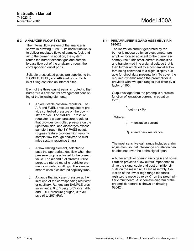
5-3 ANALYZER FLOW SYSTEM The Internal flow system of the analyzer is shown in drawing 622883. Its basic function is to deliver regulated flows of sample, fuel, and air to the burner. In addition, the system routes the burner exhaust gas and sample bypass flow out of the analyzer through the corresponding outlet ports.
Suitable pressurized gases are supplied to the SAMPLE, FUEL, and AIR inlet ports. Each inlet fitting contains an internal filter.
Each of the three gas streams is routed to the burner via a flow control arrangement consist-ing of the following elements:
1. An adjustable pressure regulator. The AIR and FUEL pressure regulators pro-vide controlled pressure on the down-stream side. The SAMPLE pressure regulator is a back-pressure regulator that provides controlled pressure on the upstream side, and discharges excess sample through the BY-PASS outlet. (Bypass feature provides high velocity sample flow through analyzer, to mini-mize system response time.)
2. A flow limiting element, selected to pass the appropriate gas flow when the pressure drop is adjusted to the correct value. The air and fuel streams utilize porous, sintered metallic restrictor ele-ments mounted in fittings. The sample stream uses a calibrated capillary tube.
3. A gauge that indicates pressure at the inlet end of the corresponding restrictor or capillary. Ranges are SAMPLE pres-sure gauge, 0 to 5 psig (0-35 kPa); AIR and FUEL pressure gauges, 0 to 30 psig (0 to 207 kPa).
5-4 PREAMPLIFIER BOARD ASSEMBLY P/N 620423 The ionization current generated by the burner is measured by an electrometer pre-amplifier located adjacent to the burner as-sembly itself This small current is amplified and transformed into a signal voltage that is then further amplified by a post amplifier be-fore being converted to a digital display suit-able for direct data presentation. To cover the required dynamic range the preamplifier is provided with two gain ranges that differ by a factor of 100.
Output voltage from the preamp is a precise function of ionization current. In equation form:
e out = -ii x Rf
Where:
ii = ionization current
Rf = feed back resistance
The most sensitive gain range includes a trim adjustment so that inter-range correlation can be obtained over the entire signal span.
A buffer amplifier offering unity gain and noise filtration provides a low output impedance to drive the signal cable and post amplifier cir-cuits on the main circuit card assembly. Se-lection of the low or high range feedback resistors is made by relay K1 on the preampli-fier circuit board. A schematic diagram of the preamplifier board is shown on drawing 620424.

Instruction Manual 748023-X
November 2002
Rosemount Analytical Inc. A Division of Emerson Process Management Theory 5-3
Model 400A
RANGE RANGE SWITCH SETTING PREAMP GAIN POST AMP GAIN
1 1 HIGH 50 2 2.5 HIGH 20 3 10 HIGH 5 4 25 HIGH 2 5 100 LOW 50 6 250 LOW 20 7 1000 LOW 5 8 RMT -- REMOTE
Table 5-1. Input Sensitivities
A variable offset current is injected into the summing node of the electrometer amplifier to compensate for background offset current. These currents influence the measurement procedure, and a variable voltage at the front panel allows the user to visually cancel these currents during the calibration procedure. Background current is due to unavoidable traces of carbonaceous material introduced into the burner flame by the fuel gas and air.
5-5 MAIN ELECTRONICS BOARD ASSEMBLY P/N 620428
a. Post Amplifier The post amplifier circuit comprises two amplifiers with various combinations of feedback resistances that are logically se-lected by the front panel RANGE switch or external inputs. The range selection process provides a total of seven possible gains corresponding to the input sensitivi-ties Table 5-1 above.
b. Digital Display The voltage originating from the signal amplifiers is made available to output terminals and directly to an analog to digi-tal converter (ADC) for data display in digital form. The ADC is termed 3-1/4 dig-
its, which implies a maximum reading of 1999. The one bit signifying over-range allows 100% excursion above the normal 99.9% range. Thus the user, depending upon span and zero offset conditions, may select the presentation to read di-rectly in percent of fullscale and still have 100% over-range capability remaining.
c. Span To compensate for various calibration gases, provision is made to vary the gain with a variable span control. The variable span, available at the front panel through a calibrated potentiometer, allows gain variation of 400%.
Table 5-2 on page 5-4 gives the fullscale sensitivity of the current measuring cir-cuitry for the various settings on the RANGE switch and SPAN control.
d. Output Circuits See Section 2-5b on page 2-5.
e. Voltage Current Output Option, P/N 620438
See Section 2-5c on page 2-5.

Instruction Manual 748023-X November 2002
5-4 Theory Rosemount Analytical Inc. A Division of Emerson Process Management
Model 400A
Fullscale Sensitivity Amps Range Switch
Setting Max Span Min Span 1 5 x 10-12 1.66 x 0-12
2.5 2 x 10-12 6.66 x 10⁻¹¹ 10 5 x 10-11 1.66 x 10⁻¹¹ 25 2 x 10'.11 6.66 x 10⁻¹⁰
100 5 x 10⁻¹⁰ 1.66 x 10⁻¹⁰ 250 2 x 10⁻¹⁰ 6.66 x 10⁻⁹ 1000 5 x 10⁻¹⁰ 1.66 x 10⁻⁹
Table 5-2. Fullscale Sensitivity
f. Remote Range Control See Section 2-5e on page 2-6. Internally all of the range terminals are pulled up to the system 5 V power supply through 10K ohm resistors and are therefore suitable for connection to any TTL or equivalent logic circuits.
5-6 TEMPERATURE CONTROL BOARD AS-SEMBLY P/N 620446
The temperature control board serves the dual function of temperature control and power distribution. See drawing 621072.
a. Temperature Controller The temperature controller is located in the heated compartment of the instru-ment. The solid state temperature sensor, in conjunction with an optically isolated solid state relay and control circuit, main-tains the internal temperature to meet per-formance specifications for the instrument. The temperature is controlled at 118°F (48°C). See drawing 620447.
b. Heater Assembly The heater assembly maintains the inte-rior of the analyzer at a constant 118°F (48°C) to minimize temperature depend-ent variations in amplifier sensitivity and to prevent changes in adsorp-
tion/desorption equilibrium of trace hydro-carbons in the internal flow system.
Electronic circuitry is shown on drawing 620429. The sensor controls the zero voltage crossing temperature controller. This on-off switching device controls ap-plication of electrical power to 150 watt resistive heating element. When the tem-perature is below the 118°F (48°C) set-point and line voltage crosses the zero voltage point, the controller switches to on and applies power to the heater. The con-troller remains on until the sensor tem-perature reaches 118°F (48°C). The controller then switches off, removing power from the heater. A blower fan circu-lates air to equalize temperature through-out the analyzer interior.
5-7 IGNITION CIRCUIT
The ignition circuit is used to light the burner flame during instrument startup. The principal circuit components are as follows:
1. Ignitor element mounted in the burner cap
2. Step-down transformer P/N 621049
3. IGNITE switch mounted on the preamp board and connected in series with the primary of transformer

Instruction Manual 748023-X
November 2002
Rosemount Analytical Inc. A Division of Emerson Process Management Theory 5-5
Model 400A
5-8 SYSTEM POWER SUPPLIES Several power supplies are used within the Model 400A for the electrical functions. These are as follows:
±12 VDC Used for most analog functions.
±5 VDC These two voltages derived from a precision reference are used for zero offset and bias requirements.
+5 VDC Used to power the digital circuit range decoding ADC display, etc.
+93 VDC Used for the burner tip polarizing voltage.
+24 VDC (Unregulated) - Used for relays.
All of the power supplies are electronically regulated with the exception of the +24 VDC supply. Shorting of one supply to another may cause damage.

Instruction Manual 748023-X November 2002
5-6 Theory Rosemount Analytical Inc. A Division of Emerson Process Management
Model 400A

Instruction Manual 748023-X
November 2002
Rosemount Analytical Inc. A Division of Emerson Process Management Service and Troubleshooting 6-1
Model 400A
SECTION 6 SERVICE AND TROUBLESHOOTING
WARNING
ELECTRICAL SHOCK HAZARD
Do not operate without doors and covers secure. Servicing requires access to live parts which can cause death or serious in-jury. Refer servicing to qualified person-nel.
For safety and proper performance this in-strument must be connected to a properly grounded three-wire source of power.
The power plug must be disconnected from the rear of the instrument before re-moving any of the boards and/or intercon-nect plugs.
6-1 SYSTEM CHECKOUT If analyzer performance is unsatisfactory, make the following tests in the sequence given.
a. Amplifier Zero Adjustment Place POWER switch at ON; RANGE switch at 1000; ZERO and SPAN potenti-ometers at 1000. With flame extin-guished, note reading on front panel indicator, or on potentiometric recorder if used. Reading should be zero; if not, ad-just trimming potentiometer R13 on ampli-fier circuit board. Potentiometer R13 is adjusted by inserting a screwdriver through the lower hole in the amplifier shield.
b. Zero Current Adjustment If a current recorder is used, verify that it reads zero. If not, adjust trimming potenti-ometer R1 on the current output board.
c. Electrical Leakage Check Turn RANGE switch from position 1000 to position 1; indicator or recorder should still read 0 ±5%. If reading is outside this range, leakage is excessive. To deter-mine the source of the leakage, discon-nect the amplifier input cable from burner, and note response of indicator or re-corder. If abnormal reading persists, leak-age is in either the cable or electronics. If reading drops to zero, leakage is in the burner. Clean burner per Section 6-2a, page 6-2. Reconnect cable to burner.
d. Flame Ignition Start up analyzer per Section Three, and attempt to ignite flame. If flame will not ig-nite refer to Section 6-3 on page 6-5, Item 2.
e. Noise Check With flame burning, observe indicator or recorder. If noise is greater than 2% of fullscale, refer to Section 6-3 on page 6-5, Item 3.
f. Overall Sensitivity Check With flame burning, supply a suitable span gas to SAMPLE inlet. Turn RANGE switch to a setting appropriate to the hy-drocarbon content of the particular span gas. Adjust SPAN control for reading of 100% on indicator or recorder. If the de-sired upscale reading is unobtainable by adjustment of the SPAN control, the fault may be in either the flow system (Section 6-3 on page 6-5, Item 4) or in the elec-tronics.
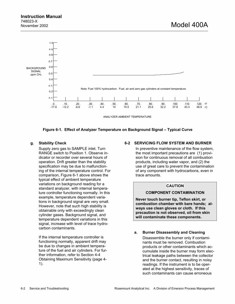
Instruction Manual 748023-X November 2002
6-2 Service and Troubleshooting Rosemount Analytical Inc. A Division of Emerson Process Management
Model 400A
0.1
0.2
0.3
0.4
0.5
0.6
0.7
0.8
0.9
1.0
0-17.6
10-12.2
20-6.6
30-1.1
404.4
5010
6015.5
7021.1
8025.6
9032.2
10037.8
11043.3
12048.9
°F°C
BACKGROUNDSIGNALppm CH4
ANALYZER AMBIENT TEMPERATURE
Note: Fuel 100% hydrocarbon. Fuel, air and zero gas cylinders at constant temperature.
Figure 6-1. Effect of Analyzer Temperature on Background Signal – Typical Curve
g. Stability Check Supply zero gas to SAMPLE inlet. Turn RANGE switch to Position 1. Observe in-dicator or recorder over several hours of operation. Drift greater than the stability specification may be due to malfunction-ing of the internal temperature control. For comparison, Figure 6-1 above shows the typical effect of ambient temperature variations on background reading for a standard analyzer, with internal tempera-ture controller functioning normally. In this example, temperature dependent varia-tions in background signal are very small. However, note that such high stability is obtainable only with exceedingly clean cylinder gases. Background signal, and temperature dependent variations in this signal, increase with level of trace hydro-carbon contaminants.
If the internal temperature controller is functioning normally, apparent drift may be due to changes in ambient tempera-ture of the fuel and air cylinders. For fur-ther information, refer to Section 4-4 Obtaining Maximum Sensitivity (page 4-1).
6-2 SERVICING FLOW SYSTEM AND BURNER In preventive maintenance of the flow system, the most important precautions are (1) provi-sion for continuous removal of all combustion products, including water vapor, and (2) the use of great care to prevent the contamination of any component with hydrocarbons, even in trace amounts.
CAUTION
COMPONENT CONTAMINATION
Never touch burner tip, Teflon skirt, or combustion chamber with bare hands; al-ways use clean gloves or cloth. If this precaution is not observed, oil from skin will contaminate these components.
a. Burner Disassembly and Cleaning Disassemble the burner only if contami-nants must be removed. Combustion products or other contaminants which ac-cumulate inside the burner may form elec-trical leakage paths between the collector and the burner contact, resulting in noisy readings. If the instrument is to be oper-ated at the highest sensitivity, traces of such contaminants can cause erroneous

Instruction Manual 748023-X
November 2002
Rosemount Analytical Inc. A Division of Emerson Process Management Service and Troubleshooting 6-3
Model 400A
readings. For best performance, it is nec-essary that the burner be kept free of any contamination.
WARNING
POSSIBLE EXPLOSION HAZARD
This analyzer uses a fuel containing hy-drogen. Leakage from the fuel contain-ment system can result in an explosion. The fuel supply and containment system, both inside and outside the analyzer, should be carefully checked for leaks upon installation, before initial startup, during routine maintenance and any time the in-tegrity of the containment system is bro-ken.
When burner requires cleaning, refer to Figure 5-1 (page 5-1) and drawing 623190 and proceed as follows:
1. Place POWER switch at OFF position and disconnect power cord.
2. Shut off fuel gas first, then air and sample gases.
3. Unscrew burner cap retainer ring and remove burner cap.
4. On combustion chamber, disconnect polarizing voltage cable and amplifier input cable.
5. Lift chimney from combustion cham-ber. Leave exhaust tubing connected to chimney unless old chimney is to be replaced.
6. Loosen clamp. Lifting straight up, re-move combustion chamber from manifold.
NOTE:
If old burner tip assembly is to be used again, do not touch it with bare hands or any materials likely to contaminate it with hydrocarbons, salt, etc.
7. Unscrew and remove burner tip as-sembly.
NOTE:
All items used for cleaning (tweezers, swabs, etc.) must be absolutely free of contamination.
8. Clean chimney assembly, combustion chamber, and burner tip assembly with alcohol, followed by a distilled water wash.
Using care not to touch internal parts, re-assemble burners as explained in the fol-lowing steps.
1. Holding burner tip assembly with clean tissue, screw finger-tight into manifold.
2. Push combustion chamber down onto manifold, taking care not to hit burner tip. Tighten clamp on combustion chamber.
3. Replace chimney on combustion chamber.
4. Replace burner cap.
5. Reconnect all leads.
b. Thermistor The thermistor sensor for the FLAME OUT indicator circuit is mounted in the burner. See Figure 5-1 (page 5-1). Ther-mistor resistance should be approximately 100K ohms at 77oF (25oC). An alternate method requires that the comparator input signal be measured at the junction of R32 and R33. When the flame is burning nor-mally, the voltage at this point will be 0.1 VDC to 0.3 VDC, indicating that the ther-mistor circuit is functional and the flame temperature is correct.

Instruction Manual 748023-X November 2002
6-4 Service and Troubleshooting Rosemount Analytical Inc. A Division of Emerson Process Management
Model 400A
c. Fuel and Air Restrictors Fuel and air restrictors are porous, sin-tered metallic, restrictor elements mounted within fittings. If a restrictor be-comes plugged, replace it. Do not attempt to clean restrictors with solvents. See drawing 622883.
d. Sample Capillary
The sample capillary is equipped with fit-tings, permitting convenient removal and replacement. If necessary, the capillary may be cleaned with acetone or methyl ethyl ketone, followed by distilled water wash. Refer to warnings in Section 6-2a, page 6-2.

Instruction Manual 748023-X
November 2002
Rosemount Analytical Inc. A Division of Emerson Process Management Replacement Parts 6-5
Model 400A
6-3 TROUBLESHOOTING For troubleshooting the electronic system, refer to the appropriate schematic at the rear of this manual. For trou-bleshooting the burner system, refer to the following:.
Symptom Probable Cause Possible Remedy Indicator shows upscale reading when flame is out.
Electrical leakage in burner assembly. Clean burner per Section 6-2a, page 6-2.
Fuel gas emerging from burner jet di-luted with other gases because fuel system is insufficiently purged.
Purge FUEL pressure regulator by allowing gas to flow for several minutes, while turning regulator alternately clockwise and counterclockwise.
AIR and/or FUEL pressure regulator improperly adjusted.
Check readings on AIR and FUEL pressure gauges. Adjust AIR pressure regulator to increase or decrease air pressure slightly.
No flow, or reduced flow, of fuel and/or air into burner combustion chamber.
Constriction in fuel and/or air passage in burner jet, restrictor, etc. Find cause of constriction and re-move.
Malfunction in igniter circuit. Remove cap from burner. Actuate IGNITE switch. Igniter should glow red. If not, check the following probable causes.
Ignite leads improperly connected. Check igniter plugs for proper contact.
Igniter burned out. Replace igniter (glow plug) as shown in drawing 623190.
Transformer circuit open. Check voltage. See drawings 620424 and 655354
Burner will not ignite.
IGNITE switch defective. Test switch for continuity. Replace if necessary. Contamination of flow system: fuel and air supplies, external pressure regula-tors, connecting tubing.
Replace fuel and/or air supply; clean or replace tubing and regulators per Sections 2-3, page 2-2.
Pressure regulator(s) and/or pressure gauge(s) clogged. Clean or replace regulators and gauges.
Indicator reading noisy
Water or condensate in burner or ex-haust line. Clean burner and exhaust line
Fuel and/or air filter clogged. Check filters; replace if necessary.
Plugged restrictor or capillary
Verify that fuel and air restrictors and sample capil-lary are open. An abnormally low background sig-nal, together with sensitivity loss, indicates plugged restrictor. Note that flame will not light unless fuel and air restrictors are open, but will not light even though sample capillary is completely closed.
Loss of sensitivity
Electrical elements of burner partially short circuited by combustion products
Disassembly and clean burner, as explained in Section 6-2a, page 6-2.
Check valve in sample pump not func-tioning. Examine check valve. Sample pressure
fluctuations Obstruction in bypass outlet. Examine bypass outlet, remove obstruction.
False flame (FLAME-ON) indi-cation of span gas produces lit-tle or no upscale deflection.
Flame may be lifting above burner tip (unusual condition).
Connect a voltmeter from ground, as viewed with door open. If flame is properly lit, the voltage will be below 0.2 VDC. If voltage is high, readjust air-fuel ratio to obtain proper ignition. Re-light burner with richer fuel and air setting. FUEL: 30 psig AIR: 2 to 5 psig.

Instruction Manual 748023-X November 2002
6-6 Service and Troubleshooting Rosemount Analytical Inc. A Division of Emerson Process Management
Model 400A

Instruction Manual 748023-X
November 2002
Rosemount Analytical Inc. A Division of Emerson Process Management Replacement Parts 7-1
Model 400A
SECTION 7 REPLACEMENT PARTS
WARNING
PARTS INTEGRITY
Tampering with or unauthorized substitution of components may adversely affect safety of this product. Use only factory-approved components for repair.
7-1 CIRCUIT BOARD REPLACEMENT POLICY In most situations involving a malfunction of a circuit board, it is more practical to replace the board than to attempt isolation and replace-ment of the individual component. The cost of test and replacement will exceed the cost of a rebuilt assembly. As standard policy, rebuilt boards are available on an exchange basis.
Because of the exchange policy covering cir-cuit boards the following list does not include individual electronic components. If circum-stances necessitate replacement of an indi-vidual component which can be identified by inspection or from the schematic diagrams, obtain the replacement component from a lo-cal source of supply.
7-2 RECOMMENDED REPLACEMENT PARTS LIST 655208 Board, Temperature Control 815187 Regulator, Sample 620423 Board , Preamp 888692 Regulator, Fuel/Air 655305 Heater in Fan Assembly 861984 Gauge, Fuel/Air 836482 Fan, Heater 617900 Glow Plug (Igniter) 621031 Cable, 16 Conductor 644055 Gauge, Sample 748262 Instruction Manual, 400A
(S/N 2000001 and up) 823484 Fuse, 2 AMP (115 VAC) 617902 Valve, Solenoid (Fuel Shutoff) 657545 Board, Flame-Out 620428 Board, Amplifier 621023 Board, Isolated Current Output, 4 to
20 mA 621017 Header 655178 Door, Clear Plastic 655203 Valve, Solenoid (Sample Shutoff)
(Option) 017154 Filter, Sample/Air
See drawing 623190 for listing of capillaries and restrictors, and for Burner Parts List.

Instruction Manual 748023-X November 2002
7-2 Replacement Parts Rosemount Analytical Inc. A Division of Emerson Process Management
Model 400A

Instruction Manual 748023-X
November 2002
Rosemount Analytical Inc. A Division of Emerson Process Management Return of Material 8-1
Model 400A
SECTION 8 RETURN OF MATERIAL
8-1 RETURN OF MATERIAL If factory repair of defective equipment is required, proceed as follows: 1. Secure a return authorization from a
Rosemount Analytical Inc. Sales Office or Representative before returning the equipment. Equipment must be returned with complete identification in accordance with Rosemount instructions or it will not be accepted. Rosemount CSC will provide the shipping address for your instrument. In no event will Rosemount be responsible for equipment returned without proper authorization and identification.
2. Carefully pack the defective unit in a sturdy box with sufficient shock absorbing material to ensure no additional damage occurs during shipping.
3. In a cover letter, describe completely: • The symptoms that determined the
equipment is faulty. • The environment in which the
equipment was operating (housing, weather, vibration, dust, etc.).
• Site from where the equipment was removed.
• Whether warranty or non-warranty service is expected.
• Complete shipping instructions for the return of the equipment.
4. Enclose a cover letter and purchase order and ship the defective equipment according to instructions provided in the Rosemount Return Authorization, prepaid, to the address provided by Rosemount CSC.
Rosemount Analytical Inc. Process Analytical Division
Customer Service Center 1-800-433-6076
If warranty service is expected, the defective unit will be carefully inspected and tested at the factory. If the failure was due to the conditions listed in the standard Rosemount warranty, the defective unit will be repaired or replaced at Rosemount’s option, and an operating unit will be returned to the customer in accordance with the shipping instructions furnished in the cover letter. For equipment no longer under warranty, the equipment will be repaired at the factory and returned as directed by the purchase order and shipping instructions.
8-2 CUSTOMER SERVICE For order administration, replacement Parts, application assistance, on-site or factory repair, service or maintenance contract information, contact:
Rosemount Analytical Inc. Process Analytical Division
Customer Service Center 1-800-433-6076
8-3 TRAINING A comprehensive Factory Training Program of operator and service classes is available. For a copy of the Current Operator and Service Training Schedule contact the Technical Services Department at:
Rosemount Analytical Inc. Process Analytical Division
Customer Service Center 1-800-433-6076

Instruction Manual 748023-X November 2002
8-2 Return of Material Rosemount Analytical Inc. A Division of Emerson Process Management
Model 400A

WARRANTY
Goods and part(s) (excluding consumables) manufactured by Seller are warranted to be free from defects in workmanship and material under normal use and service for a period of twelve (12) months from the date of shipment by Seller. Consumables, glass electrodes, membranes, liquid junctions, electrolyte, o-rings, etc., are warranted to be free from defects in workmanship and material under normal use and service for a period of ninety (90) days from date of shipment by Seller. Goods, part(s) and consumables proven by Seller to be defective in workmanship and/or material shall be replaced or repaired, free of charge, F.O.B. Seller's factory provided that the goods, part(s) or consumables are returned to Seller's designated factory, transportation charges prepaid, within the twelve (12) month period of warranty in the case of goods and part(s), and in the case of consumables, within the ninety (90) day period of warranty. This warranty shall be in effect for replacement or repaired goods, part(s) and the remaining portion of the ninety (90) day warranty in the case of consumables. A defect in goods, part(s) and consumables of the commercial unit shall not operate to condemn such commercial unit when such goods, part(s) and consumables are capable of being renewed, repaired or replaced.
The Seller shall not be liable to the Buyer, or to any other person, for the loss or damage directly or indirectly, arising from the use of the equipment or goods, from breach of any warranty, or from any other cause. All other warranties, expressed or implied are hereby excluded.
IN CONSIDERATION OF THE HEREIN STATED PURCHASE PRICE OF THE GOODS, SELLER GRANTS ONLY THE ABOVE STATED EXPRESS WARRANTY. NO OTHER WARRANTIES ARE GRANTED INCLUDING, BUT NOT LIMITED TO, EXPRESS AND IMPLIED WARRANTIES OR MERCHANTABILITY AND FITNESS FOR A PARTICULAR PURPOSE.
Limitations of Remedy. SELLER SHALL NOT BE LIABLE FOR DAMAGES CAUSED BY DELAY IN PERFORMANCE. THE SOLE AND EXCLUSIVE REMEDY FOR BREACH OF WARRANTY SHALL BE LIMITED TO REPAIR OR REPLACEMENT UNDER THE STANDARD WARRANTY CLAUSE. IN NO CASE, REGARDLESS OF THE FORM OF THE CAUSE OF ACTION, SHALL SELLER'S LIABILITY EXCEED THE PRICE TO BUYER OF THE SPECIFIC GOODS MANUFACTURED BY SELLER GIVING RISE TO THE CAUSE OF ACTION. BUYER AGREES THAT IN NO EVENT SHALL SELLER'S LIABILITY EXTEND TO INCLUDE INCIDENTAL OR CONSEQUENTIAL DAMAGES. CONSEQUENTIAL DAMAGES SHALL INCLUDE, BUT ARE NOT LIMITED TO, LOSS OF ANTICIPATED PROFITS, LOSS OF USE, LOSS OF REVENUE, COST OF CAPITAL AND DAMAGE OR LOSS OF OTHER PROPERTY OR EQUIPMENT. IN NO EVENT SHALL SELLER BE OBLIGATED TO INDEMNIFY BUYER IN ANY MANNER NOR SHALL SELLER BE LIABLE FOR PROPERTY DAMAGE AND/OR THIRD PARTY CLAIMS COVERED BY UMBRELLA INSURANCE AND/OR INDEMNITY COVERAGE PROVIDED TO BUYER, ITS ASSIGNS, AND EACH SUCCESSOR INTEREST TO THE GOODS PROVIDED HEREUNDER.
Force Majeure. Seller shall not be liable for failure to perform due to labor strikes or acts beyond Seller's direct control.

Instruction Manual 748023-X November 2002
© Rosemount Analytical Inc. 2002
EMERSON PROCESS MANAGEMENT ROSEMOUNT ANALYTICAL INC. PROCESS ANALYTIC DIVISION 1201 N. Main St. Orrville, OH 44667-0901 T (330) 682-9010 F (330) 684-4434 E [email protected]
ASIA - PACIFIC Fisher-Rosemount Singapore Private Ltd. 1 Pandan Crescent Singapore 128461 Republic of Singapore T 65-777-8211 F 65-777-0947 http://www.processanalytic.com
EUROPEAN TECHNOLOGY CENTER Fisher-Rosemount GmbH & Co. Industriestrasse 1 63594 Hasselroth Germany T 49-6055-884 0 F 49-6055-884209
EUROPE, MIDDLE EAST, AFRICA Fisher-Rosemount Ltd. Heath Place Bognor Regis West Sussex PO22 9SH England T 44-1243-863121 F 44-1243-845354
LATIN AMERICA Fisher - Rosemount Av. das Americas 3333 sala 1004 Rio de Janeiro, RJ Brazil 22631-003 T 55-21-2431-1882
Model 400A