Embed Size (px)
Citation preview

Model 3081 pH/ORPSmart Two-Wire Microprocessor Transmitter
Instruction ManualPN 51-3081pH/rev.DAugust 2002

ESSENTIAL INSTRUCTIONSREAD THIS PAGE BEFORE PROCEEDING!
Rosemount Analytical designs, manufactures, and tests its products to meetmany national and international standards. Because these instruments aresophisticated technical products, you must properly install, use, and maintainthem to ensure they continue to operate within their normal specifications. Thefollowing instructions must be adhered to and integrated into your safetyprogram when installing, using, and maintaining Rosemount Analyticalproducts. Failure to follow the proper instructions may cause any one of thefollowing situations to occur: Loss of life; personal injury; property damage;damage to this instrument; and warranty invalidation.
• Read all instructions prior to installing, operating, and servicing the product.If this Instruction Manual is not the correct manual, telephone 1-800-654-7768 and the requested manual will be provided. Save this InstructionManual for future reference.
• If you do not understand any of the instructions, contact your Rosemountrepresentative for clarification.
• Follow all warnings, cautions, and instructions marked on and supplied withthe product.
• Inform and educate your personnel in the proper installation, operation, andmaintenance of the product.
• Install your equipment as specified in the Installation Instructions of theappropriate Instruction Manual and per applicable local and national codes.Connect all products to the proper electrical and pressure sources.
• To ensure proper performance, use qualified personnel to install, operate,update, program, and maintain the product.
• When replacement parts are required, ensure that qualified people usereplacement parts specified by Rosemount. Unauthorized parts andprocedures can affect the product’s performance and place the safeoperation of your process at risk. Look alike substitutions may result in fire,electrical hazards, or improper operation.
• Ensure that all equipment doors are closed and protective covers are inplace, except when maintenance is being performed by qualified persons, toprevent electrical shock and personal injury.
CAUTIONIf a Model 275 Universal Hart®
Communicator is used with thesetransmitters, the software within theModel 275 may require modification.
If a software modification is required,please contact your local Emerson ProcessManagement Service Group or NationalResponse Center at 1-800-654-7768.
Emerson Process ManagementRosemount Analytical Inc.2400 Barranca ParkwayIrvine, CA 92606 USATel: (949) 757-8500Fax: (949) 474-7250
http://www.raihome.com
© Rosemount Analytical Inc. 2004

WHAT YOU NEED TO KNOW BEFORE INSTALLING AND WIRING A ROSEMOUNT ANALYTICAL
SENSOR TO THE MODEL 3081 pH/ORP TRANSMITTER
1. THE MODEL NUMBER OF THE SENSOR• Look on the label.• Also note the model option string.• If the label is missing or unreadable, see the
flowcharts on pages 28 through 30.Write the sensor model number here
2. THE TYPE OF TEMPERATURE ELEMENT• Look on the label.• If the label is missing or unreadable, measure the
resistance between the RTD leads.Write the temperature element RTD here
3. THE LOCATION OF THE PREAMPLIFIER: INSIDE OR OUTSIDE THE TRANSMITTER?• If the sensor is wired through a junction box, the preamplifier is ALWAYS in the junction box or
the sensor.
If resistance is . . . the RTD is . . .about 110 ohms Pt 100about 3000 ohms Balco 3K

• If the sensor is wired directly to the transmitter, the preamplifier can be in either the sensoror the transmitter.
• Look at the wires in the sensor cable. A GREEN wire means the preamplifier is in the sen-sor. An coaxial cable means the preamplifier is in the transmitter. A coaxial cable is aninsulated wire surrounded by a braided metal shield. The wire terminates in either a BNCconnector or an ORANGE wire with a CLEAR shield.Write the preamplifier location here
CAN YOU USE THE QUICK START GUIDE ON THE FOLLOWING PAGE?
Use the Quick Start Guide if . . .1. you are NOT using a HART communicator, 2. you do NOT require an intrinsically safe or explosion-proof installation, 3. you are NOT measuring ORP, 4. you do NOT require transmitter setup beyond programming the 4-20 mA output, 5. you are NOT using a a sensor-mounted junction box or a remote junction box,6. you are NOT using a sensor made by another manufacturer,7. you are using one of the following sensors:
Note: Only the model option numbers needed to select the correct wiring diagram in theQuick Start Guide are shown. Other model option numbers are not shown.
If you cannot use the Quick Start Guide, turn to Section 2.0 of the instruction manual.
Base Model RTD Preamplifier located Model Option (note)381+ Pt 100 in sensor (green wire) 381+ -55381+ Pt 100 in transmitter (orange wire) 381+ -52385+ Pt 100 in sensor (green wire) 385+ -03385+ Pt 100 in transmitter (orange wire) 385+ -04396P Pt 100 in transmitter (orange wire) 396P-02-54396P Pt 100 in sensor (green wire) 396P-01-55396P Pt 100 in transmitter (orange wire) 396P-02-55396R Pt 100 in transmitter (orange wire) 396R-54

QUICK START GUIDE FOR MODEL 3081pH/ORPBefore using this Quick Start Guide, please read “WHAT YOU NEED TO KNOW BEFOREINSTALLING AND WIRING A ROSEMOUNT ANALYTICAL SENSOR TO THE MODEL 3081pH/ORP TRANSMITTER” on the preceding page.
Section 1.1 Setup for the Models 381+-52, 385+-04, 396P-02-54, 396P-02-55 and 396R-54 without a junction boxA. The factory setting of the preamplifier switch is in the appropriate location, so no adjustment is necessary.B. Mount the transmitter in the desired location. Most installations use PN 2002577, pipe mounting bracket.C. Continue the start up with Section 2 Wiring.
Section 1.2 Setup for Sensor Models 381+-55, 385+-03, and 396P-01-55 without a junction boxA. This section shows how to set the preamplifier switch and should be done prior to installation of the transmitter.B. Loosen the cover lock nut on the Model 3081pH/ORP transmitter until the tab disengages from the circuit end cap.
Unscrew and remove the cap. Unscrew the three bolts holding the circuit board stack in the enclosure.C. Pull up on the display board. Do not disconnect the ribbon cable between it and the CPU board. The CPU and analog
boards are joined by a pin and socket connector along the bottom edge of the boards. Carefully pull the boards apart andremove the CPU board. The analog board is on the bottom and remains in the enclosure. See Figure 1 below.
D. The analog board is shaped like a circle with an arc missing. Directly opposite the straight side is a slide switch. Changethe switch position to the "sensor or j-box" setting by sliding the switch closer to the edge of the board. See Figure 2 below.
E. To reassemble the stack, place the display board on the CPU board. Be sure the display board is properly oriented. Thesmall square window (the infrared detector for the remote controller) marks the top of the board. Insert the three boltsthrough the holes. Align the bolts with the standoffs on the analog board and position the display and CPU boards on theanalog board. SIf the boards are properly aligned, the bolts will drop in place. Press along the bottom of the stack to seatthe pin and socket connector. Tighten the bolts, replace the cap and cover lock nut.
F. Mount the transmitter in the desired location. Most installations use PN 2002577, pipe mounting bracket.
FIGURE 2
FIGURE 1

Section 2 WiringA. Wire sensor Model 381+-55, 385+-03, or 396P-01-55 directly to the transmitter as shown in Figure 3.B. Wire sensor Model 381+-52, 385+-04, 396P-02-55, 396P-02-55, or 396R-54 as shown in Figure 4.C. Wire the 12 - 42.4 Vdc power supply to TB-15 (- 4 - 20 mA) and TB-16 (+ 4 - 20 mA).
Section 3 Power up and CalibrationA. Apply dc power to the transmitter.B. Remove the red protective "boot" from the sensor end. Rinse with deionized water and gently pat dry with a tissue (don't
wipe or rub). Place the pH sensor in the first buffer. Install the batteries in the remote controller.Note: A pH measurement is only as good as the calibration, and the calibration is only as good as the buffersused. A careful buffer calibration is the first step in making an accurate pH measurement. For best results, cali-brate with buffers having the same temperature as the process. Allow time for the sensor and buffers to reach thesame temperature. If the process temperature is more than 10°°C different from the buffer, allow at least 20 min-utes. Be careful using buffers at high temperatures because the pH of many buffers is undefined above 60°C. Seethe main instruction manual for further information.
C. Aim the infrared remote controller (IRC) at the LCD display.Press CAL . CALIbrAtE will appear.Press ENTER . CAL bF1 will appear.
D. With the sensor in the first buffer, be sure the glass bulb and the temperature element are completely submerged (i.e. 3inches). Do not let the weight of the sensor rest on the glass bulb. Swirl the sensor to dislodge trapped bubbles.Press ENTER . bF1 will flash until reading is stable. The measured pH value will appear in the main display.Press or until the small number next to bF1 matches the nominal pH buffer value (i.e. 4.01 pH).Press ENTER to save the first calibration point. CAL bF2 will appear.
E. Remove the sensor from the first buffer, rinse, and place in the second buffer.Press ENTER . bF2 will flash until the reading is stable. The measured pH value will appear in the main display.Press or until the small number next to bF2 matches the nominal pH buffer value (i.e. 10.00 pH).Press ENTER to save the second calibration point.
F. Press RESET to return to the process display. The calibration is complete.G. Place the sensor in the process. The start up is complete, although the following optional procedure may be useful.
Section 4 Output (OPTIONAL)A. This optional procedure assigns specific pH values to the 4 - 20 mA output. The factory default is set to 0.00 pH at 4 mA
and 14.00 pH at 20 mA.Press PROG . OutPut will appear.Press ENTER . 4 MA will appear. Use the arrow keys to change the displayed number to the desired pH.Press ENTER to save. 20 MA will appear. Use the arrow keys to change the displayed number to the desired pH.Press ENTER to save.Press RESET to return to the process display.
NOTES: 1. INSTRUMENT JUMPER SUPPLIED BY CUSTOMER.2. DO NOT CONNECT BLUE WIRE INSIDE TRANSMITTER. INSULATE STRIPPED
END OF BLUE WIRE.
FIGURE 3 FIGURE 4

QUICK REFERENCE GUIDEMODEL 3081PH/ORP
Automatic Buffer CalibrationNote: A pH measurement is only as good as the calibration, and the calibration is only as good as the buffers used. For bestresults, calibrate with buffers having the same temperature as the process. Allow time for the sensor and buffers to reach thesame temperature. If the process temperature is more than 10°C different from the buffer, allow at least 20 minutes. Be carefulusing buffers at high temperatures. The pH of many buffers is undefined above 60°C. See the main instruction manual for fur-ther information.A. Aim the infrared remote controller (IRC) at the LCD display.
Press HOLD on the IRC. HoLd OFF will appear.Press to toggle the display to HoLd On.Press ENTER to engage hold mode. The HOLD indicator will appear to the left of the pH value.
B. Press CAL . CALIbrAtE will appear.Press ENTER . CAL bF1 will appear.
C. With the sensor in the first buffer, be sure the glass bulb and the temperature element are completely submerged (about 3 inches deep). Do not let the weight of the sensor rest on the glass bulb. Swirl the sensor to dislodge trapped bubbles.Press ENTER . bF1 will flash until reading is stable. The measured pH value will appear in the main display.Press or until the small number next to bF 1 matches the nominal pH buffer value (i.e., 4.01 pH).Press ENTER to save the first calibration point. CAL bF2 will appear.
D. Remove the sensor from the first buffer, rinse and place in the second buffer.Press ENTER . bF2 will flash until the reading is stable. Press or until the small number next to bF 2 matches the nominal pH buffer value (i.e., 10.00 pH).Press ENTER to save the second calibration point.
E. The calibration is complete, but the transmitter remains in the CALIbrAtE sub-menu for two minutes after ENTER is pressed. Press RESET to return to the process display immediately.
F. Place sensor in the process.G. (Optional) For maintenance purposes, track the slope of the pH electrode. The slope value of a new electrode is 59mVper pH unit, and this value falls over time. The sensor should be changed when the slope nears 47.5mV per pH. To viewthe slope value, use the following steps.
Press CAL . CALIbrAtE will appear.Press NEXT . Std will appear.Press ENTER . The current pH value will appear next to Std.Press ENTER . SLOPE and the current slope value will appear. Record this number as the slope value.Press RESET to return to the process display.
H. After calibration, press HOLD . HoLd On will display. Press to toggle the display to HoLd Off. Press ENTER to save this into memory. The HOLD indicator on the display will turn off.
Standardizing to Match a Reference InstrumentNote: Standardization does not perform a true calibration. Regular buffer calibrations are still needed to update the sensorslope value. For best results take the grab sample from a point as close as possible to the pH sensor and measure the sampleat the same temperature as the process. A. Aim the infrared remote controller (IRC) at the LCD display.
Press HOLD on the IRC. HoLd OFF will appear.Press to toggle the display to HoLd On.Press ENTER to engage the hold mode. The HOLD indicator will appear to the left of the pH value.
B. Press CAL . CALIbrAtE will appear.Press NEXT . Std will appear.Press ENTER . The measured value will appear.
C. Take a grab sample of the process and measure it with your reference instrument. Use the editing keys to adjust the valueon the Model 3081pH/ORP to match the reference instrument. Press ENTER to save the corrected pH value.
D. If the value is acceptable, the sensor slope is displayed. The slope has not been changed.E. Press RESET to return to the process display. F. After calibration, press HOLD . HoLd On will display.
Press to toggle the display to HoLd Off. Press ENTER to save this into memory. The HOLD indicator on the display will turn off.

HART Communicator Fast Key Sequences
Technical Support Hotline:For assistance with technical problems, please call the Customer Support Center (CSC). The CSC is staffed from5:00am to 5:00pm PST.
Phone (US only): 800-854-8257 Phone: 949-757-8500Fax: 949-863-9159 World Wide Web: www.raihome.com
PROGRAMCALIBRATE
OutPut
GIMP 1000 V Er 81PH.21 tEMP 25 CInPut 58.9 ShoW FLt
nonE
rIMP 10
dIAGnOStIC tEMP bUFFErdISPLAY ISOPOtntAL SIM OUtPUt
CALIbrAtE Std tEMP AdJ
tEMP 25.0
4 MA 00.00
20MA 14.00
HoLd 21.00
FAULt 22.00
dPn 0.00
tAUtO On
tMAn 25.0
tC 100-3
tYPE PH
tEMP C
OUtPUt Cur
COdE 000
bAUtO On
bUFFEr Std
tIME 10
PH 00.02
tCOEF 00.00
ISO 07.00
Snr 07.00
tESt 12.00rOFFSt 060
dIAG OFF
IMPtC ON
GWH 1000
GFH 1500
GWL 020
GFL 010
CAL 000
rEF LO
rFH 140
rWH 040
rWL 000
rFL 000
CAL bF1
bF 1
bF1 4.01
CAL bF2
bF 2
bF2 10.01
DIAGNOSE
Std 7.00
SLOPE 59.01
MENU
Sub-menu
PROMPT
Diag Message
Menu Tree for pH
Buffer Calibration2 3 1 1
Standardize2 3 2 1
Trim Analog Output2 4
Toggle Hold Mode2 5
pH Upper Range Value3 2 2
pH Lower Range Value3 2 1
View pH value1 1 1
View Analog Output1 2
View Transmitter Status1 3

i
MODEL 3081 pH/ORP TABLE OF CONTENTS
MODEL 3081 PH/ORPMICROPROCESSOR TRANSMITTER
TABLE OF CONTENTS
Section Title Page1.0 DESCRIPTION AND SPECIFICATIONS ................................................................ 11.1 Features................................................................................................................... 11.2 Accessories.............................................................................................................. 21.3 Specifications - General for Model 3081 pH/ORP.................................................... 31.4 Specifications - pH ................................................................................................... 41.5 Specifications - ORP................................................................................................ 41.6 Ordering Information ............................................................................................... 4
2.0 INSTALLATION ....................................................................................................... 72.1 Unpacking and Inspection........................................................................................ 72.2 Pre-Installation Set Up ............................................................................................. 72.3 Orienting the Display Board ..................................................................................... 10 2.4 Mechanical Installation............................................................................................. 102.5 Power Supply/Current Loop..................................................................................... 13
3.0 WIRING.................................................................................................................... 143.1 General Information ................................................................................................. 14 3.2 Wiring Diagrams for pH and ORP Sensors.............................................................. 15
4.0 INTRINSICALLY SAFE AND EXPLOSION PROOF............................................... 314.1 Intrinsically Safe Installations................................................................................... 314.2 Explosion Proof Installations.................................................................................... 31
5.0 OPERATION WITH REMOTE CONTROLLER ....................................................... 375.1 Displays ................................................................................................................... 375.2 Infrared Remote Controller (IRC)............................................................................. 385.3 Menu Tree - pH ........................................................................................................ 395.4 Diagnostic Messages - pH ....................................................................................... 395.5 Menu Tree - ORP..................................................................................................... 405.6 Diagnostic Messages - ORP.................................................................................... 405.7 Security .................................................................................................................... 41
6.0 OPERATION WITH MODEL 275............................................................................. 426.1 Note on Model 275 HART Communicator................................................................ 426.2 Connecting the HART Communicator...................................................................... 426.3 Operation ................................................................................................................. 43
7.0 CALIBRATION OF pH MEASUREMENTS ............................................................. 487.1 General .................................................................................................................... 487.2 Entering and Leaving the Calibrate Menu................................................................ 487.3 Using the Hold Function........................................................................................... 487.4 Temperature Calibration........................................................................................... 497.5 Auto Calibration ....................................................................................................... 507.6 Manual Calibration ................................................................................................... 527.7 Making the Transmitter Reading Match a Second pH Meter (Standardization) ....... 54

MODEL 3081 pH/ORP TABLE OF CONTENTS
TABLE OF CONTENTS CONT’D
ii
8.0 PROGRAMMING FOR pH MEASUREMENTS....................................................... 568.1 General .................................................................................................................... 568.2 Entering and Leaving the Program Menu ................................................................ 568.3 Output Ranging........................................................................................................ 588.4 Diagnostic Parameters............................................................................................. 608.5 Temperature Related Settings ................................................................................. 648.6 Display Units ............................................................................................................ 668.7 Buffer Calibration Parameters.................................................................................. 678.8 Isopotential Parameters ........................................................................................... 698.9 Generating a Test Current........................................................................................ 71
9.0 CALIBRATION OF ORP MEASUREMENTS .......................................................... 729.1 General .................................................................................................................... 729.2 Entering and Leaving the Calibrate Menu................................................................ 729.3 Using the Hold Function........................................................................................... 72 9.4 Temperature Calibration........................................................................................... 739.5 Standardization ........................................................................................................ 74
10.0 PROGRAMMING FOR ORP MEASUREMENTS.................................................... 7510.1 General .................................................................................................................... 7510.2 Entering and Leaving the Program Menu ................................................................ 7510.3 Output Ranging........................................................................................................ 7710.4 Diagnostic Parameters............................................................................................. 7910.5 Temperature Element............................................................................................... 8210.6 Display Units ............................................................................................................ 8310.7 Generating a Test Current........................................................................................ 84
11.0 MAINTENANCE ...................................................................................................... 8511.1 Overview .................................................................................................................. 8511.2 Transmitter Maintenance ......................................................................................... 8511.3 pH Sensor Maintenance .......................................................................................... 86 11.4 ORP Sensor Maintenance ....................................................................................... 8711.5 Calibration................................................................................................................ 88
12.0 TROUBLESHOOTING ........................................................................................... 8912.1 Warning and Fault Messages .................................................................................. 8912.2 Calibration Errors ..................................................................................................... 9012.3 Troubleshooting - General ....................................................................................... 9012.4 Troubleshooting When a Diagnostic Message is Showing ...................................... 9012.5 Troubleshooting When No Diagnostic Message is Showing.................................... 10212.6 Systematic Troubleshooting..................................................................................... 10712.7 Displaying Diagnostic Variables............................................................................... 11012.8 Testing the Transmitter by Simulating pH ................................................................ 11012.9 Factory Assistance and Repairs .............................................................................. 113

iii
MODEL 3081 pH/ORP TABLE OF CONTENTS
TABLE OF CONTENTS CONT’D
13.0 pH MEASUREMENTS............................................................................................. 11413.1 General .................................................................................................................... 11413.2 Measuring Electrode ................................................................................................ 11513.3 Reference Electrode ................................................................................................ 11513.4 Liquid Junction Potential .......................................................................................... 11613.5 Converting Voltage to pH ......................................................................................... 11613.6 Glass Electrode Slope ............................................................................................. 11713.7 Buffers and Calibration ............................................................................................ 11713.8 Isopotential pH ......................................................................................................... 11813.9 Junction Potential Mismatch .................................................................................... 11813.10 Sensor Diagnostics .................................................................................................. 11913.11 Shields, Insulation, and Preamplifiers...................................................................... 119
14.0 ORP MEASUREMENTS.......................................................................................... 12014.1 General .................................................................................................................... 12014.2 Measuring Electrode ................................................................................................ 12114.3 Reference Electrode ................................................................................................ 12114.4 Liquid Junction Potential .......................................................................................... 12114.5 Relating Cell Voltage to ORP................................................................................... 12214.6 ORP, Concentration, and pH.................................................................................... 12214.7 Interpreting ORP Measurements ............................................................................. 12314.8 Calibration................................................................................................................ 124
15.0 THEORY - REMOTE COMMUNICATIONS ............................................................. 12615.1 Overview of HART Communications........................................................................ 12615.2 HART Interface Devices........................................................................................... 12615.3 AMS Communication ............................................................................................... 127
16.0 GLOSSARY............................................................................................................. 128
17.0 RETURN OF MATERIAL......................................................................................... 134

iv
MODEL 3081 pH/ORP TABLE OF CONTENTS
TABLE OF CONTENTS CONT’DLIST OF FIGURES
Number Title Page2-1 Model 3081 pH/ORP Transmitter - Exploded Drawing of Circuit Board Stack ......... 82-2 Model 3081 pH/ORP Transmitter - Analog Board .................................................... 92-3 Model 3081 pH/ORP Transmitter - CPU Board........................................................ 102-4 Mounting the Model 3081 pH/ORP Transmitter on a Flat Surface ........................... 112-5 Using the Pipe Mounting Kit to Attach the Model 3081 pH/ORP Transmitter to a Pipe . 122-6 Load/Power Supply Requirements .......................................................................... 132-7 Power Supply/Current Loop Wiring .......................................................................... 133-1 Wiring and Preamplifier Configurations for pH and ORP Sensors ........................... 143-2 Wire Functions for Models 399-02, 399-09, 381pH-30-41, and 381pHE-31-41.......
before removing BNC and terminating cable ........................................................... 183-3 Wire Functions for Models 399-02, 399-09, 381pH-30-41, and 381pHE-31-41.......
after removing BNC and terminating cable. Wire Functions for Models ..................399-09-10-62, 381pH-30-42, and 381pHE-31-42 as received ................................. 18
3-4 Wiring Diagram for Models 399-02, 399-09, 381pH-30-41, and 381pHE-31-41 after removing BNC and terminating cable. Wiring Diagram for Models ..399-09-10-62, 381pH-30-42, and 381pHE-31-42 as received. Wiring directly to the transmitter. ... 18
3-5 Wiring Diagram for Models 399-02, 399-09, 381pH-30-41 after removing BNC andterminating cable. Wiring Diagram for Model 399-09-10-62, 381pH-30-42, and .....381pHE-31-42 as received. Wiring through a remote junction box to the transmitter . 18
3-6 Wire Functions for Models 397-50, 397-54, 396-50, 396-54, 396R-50-60, 396R-54-60,389-02-50, and 389-02-54 before removing BNC and terminating cable................. 19
3-7 Wire Functions for Models 397-50, 397-54, 396-50, 396-54, 396R-50-60, 396R-54-60,389-02-50, and 389-02-54 after removing BNC and terminating cable. Wire .........Functions for Models 397-54-62, 396-54-62, and 389-02-54-62 as received .......... 19
3-8 Wiring Diagram for Models 397-50, 397-54, 396-50, 396-54, 389-02-50, and.........389-02-54 after removing BNC and terminating cable. Wiring Diagram for ............Models 397-54-62, 396-54-62, and 389-02-54-62 as received. Wiring Directly.......to the Transmitter ................................................................................................... 19
3-9 Wiring Diagram for Models 397-50, 397-54, 396-50, 396-54, 396R-50-60, 396R-54-60,389-02-50, and 389-02-54 after removing BNC and terminating cable. Wiring ......Diagram for Models 397-54-62, 396-54-62, and 389-02-54-62 as received. ..........Wiring Through a Remote Junction Box to the Transmitter ..................................... 19
3-10 Wire Functions for Models 396R-50, 396R-54, 396R-54-61, 396P-02-50, ..............396P-02-54, 396P-02-55, 385+-04, and 381+-41-52 ............................................... 20
3-11 Wiring Diagram for Models 396R-50, 396R-54, 396R-54-61, 396P-02-50, 396P-02-54, 396P-02-55, 385+-04, and 381+-41-52. Wiring Directly to the Transmitter ............ 20
3-12 Wiring Diagram for Models 396R-50, 396R-54, 396R-54-61, 396P-02-50, .............396P-02-54, 396P-02-55, 385+-04, and 381+-41-52. Wiring Through a Sensor-....Mounted Junction Box to the Transmitter ................................................................ 20
3-13 Wire Functions for Models 396P-01-55, 385+-03, 381+-40-55, and 381+-43-55 .... 213-14 Wiring Diagram for Models 396P-01-55, 385+-03, 381+-40-55, and 381+-43-55.... 213-15 Wire Functions for Model 385+-02 ........................................................................... 223-16 Wiring Diagram for Model 385+-02 .......................................................................... 223-17 Wire Functions for Model 328A-07........................................................................... 233-18 Wiring Diagram for Model 328A ............................................................................... 233-19 Wiring Diagram for Model 320HP-10-55 .................................................................. 24 3-20 Wiring Diagram for Model 320HP-10-58 .................................................................. 243-21 Wire Functions for Model 399-33 ............................................................................. 253-22 Wiring Diagram for Model 399-33 ............................................................................ 25

v
MODEL 3081 pH/ORP TABLE OF CONTENTS
TABLE OF CONTENTS - CONT’DLIST OF FIGURES - CONT’D
Number Title Page3-23 Procedure for Removing BNC Connector and Preparing Coaxial Cable for ............
Connection to the Model 3081 pH/ORP Transmitter ................................................ 263-24 Preparation of Raw Connecting Cable (PN 9200273).............................................. 274-1 Intrinsically Safe BASEEFA Model 3081 pH/ORP Label .......................................... 314-2 FMRC Installation for Model 3081 pH/ORP Transmitter........................................... 324-3 CSA Installation for Model 3081 pH/ORP Transmitter.............................................. 344-4 Explosion-Proof Installation for Model 3081 pH/ORP Transmitter............................ 365-1 Process Display Screen ........................................................................................... 375-2 Program Display Screen .......................................................................................... 375-3 Infrared Remote Controller....................................................................................... 385-4 Menu Tree for pH ..................................................................................................... 395-5 Menu Tree for ORP ................................................................................................. 406-1 Connecting the HART Communicator ...................................................................... 426-2 Menu Tree for pH (HART) ........................................................................................ 446-3 Menu Tree for ORP (HART) ..................................................................................... 468-1 Suggested Glass Impedance Warning and Failure Limits ....................................... 608-2 Suggested Warning and Failure Limits for Low Impedance Reference Electrodes . 618-3 Suggested Warning and Failure Limits for High Impedance Glass Reference .......
Electrodes ................................................................................................................ 6110-1 Suggested Warning and Failure Limits for Low Impedance Reference Electrodes . 7910-2 Suggested Glass Impedance Warning and Failure Limits for a Glass Reference....
Electrode .................................................................................................................. 7911-1 Exploded View of Model 3081 pH/ORP Transmitter................................................. 8511-2 Checking the Potential of the Reference Electrode.................................................. 8712-1 Warning Annunciation............................................................................................... 8912-2 Fault Annunciation.................................................................................................... 8912-3 Three-Wire RTD .................................................................................................... 9612-4 Temperature Simulation into the Model 3081 pH/ORP Transmitter ......................... 9712-5 Troubleshooting Flow Chart/Preamplifier in Sensor-Mounted Junction Box or ........
Remote Junction Box ............................................................................................... 10812-6 Troubleshooting Flow Chart/Preamplifier in Transmitter or Built into Sensor ........... 10912-7 pH Simulation When the Preamplifier is Located in the Transmitter ........................ 11112-8 pH Simulation When the Preamplifier is Located in a Remote Junction Box or.......
in a Sensor-Mounted Junction Box .......................................................................... 11112-9 Simulate pH Through Model 381+ Sensor Preamplifier ........................................... 11213-1 pH Measurement Cell............................................................................................... 11413-2 Measuring Electrode (pH) ........................................................................................ 11513-3 Cross-Section Through the pH Glass....................................................................... 11513-4 Reference Electrode................................................................................................. 11613-5 The Origin of Liquid Junction Potential..................................................................... 11613-6 Glass Electrode Slope.............................................................................................. 11713-7 Two-Point Buffer Calibration..................................................................................... 11813-8 Liquid Junction Potential Mismatch .......................................................................... 11914-1 ORP Measurement Cell ........................................................................................... 12014-2 Measuring Electrode (ORP) ..................................................................................... 12114-3 Reference Electrode................................................................................................. 12114-4 The Origin of Liquid Junction Potential..................................................................... 12214-5 Electrode Potential ................................................................................................... 12214-6 ORP Measurement Interpretation............................................................................. 12315-1 HART Communications ........................................................................................... 126 15-2 AMS Main Menu Tools ............................................................................................. 127

vi
MODEL 3081 pH/ORP TABLE OF CONTENTS
TABLE OF CONTENTS CONT’D
LIST OF TABLESNumber Title Page
3-1 Wiring Diagrams for Model 399 Sensors.................................................................. 153-2 Wiring Diagrams for Model 397 Sensors.................................................................. 153-3 Wiring Diagrams for Model 396R Sensors ............................................................... 153-4 Wiring Diagrams for Model 396P Sensors ............................................................... 163-5 Wiring Diagrams for Model 396 Sensors.................................................................. 163-6 Wiring Diagrams for Model 389 Sensors.................................................................. 163-7 Wiring Diagrams for Model 385+ Sensors................................................................ 173-8 Wiring Diagrams for Model 381+ Sensors................................................................ 173-9 Wiring Diagrams for Model 381pHE and 381pH Sensors ........................................ 173-10 Wiring Diagrams for Model 328A Sensors ............................................................... 173-11 Wiring Diagrams for Model 320HP Sensors............................................................. 178-1 pH Settings List ....................................................................................................... 578-2 pH Values of Standard Buffer Solutions and the Temperature Range over which ...
pH Values are Defined ............................................................................................. 678-3 pH Values of Commercial (technical) Buffers and the Temperature Range over .....
which pH Values are Defined .................................................................................. 688-4 Standard and Technical Buffers Recognized by the Model 3081 pH Transmitter .... 6810-1 ORP Settings List .................................................................................................... 7611-1 Replacement Parts for Model 3081 pH Transmitter ................................................ 8612-1 RTD Resistance Values ........................................................................................... 96

1
MODEL 3081 pH/ORP SECTION 1.0DESCRIPTION AND SPECIFICATIONS
SECTION 1.0DESCRIPTION AND SPECIFICATIONS
1.1 Features1.2 Accessories1.3 Specifications - General for Model 3081 pH/ORP1.4 Specifications - pH1.5 Specifications - ORP1.6 Ordering Information
• CHANGING FROM pH TO ORP operation takes only seconds.• REMOTE COMMUNICATION IS SIMPLE; use the hand-held infrared remote controller or any
HART® compatible device.• LARGE TWO LINE DISPLAY shows pH or ORP, temperature, and output signal.• SIMPLE, INTUITIVE MENUS make programming and calibrating easy.• AUTOMATIC TWO-POINT BUFFER CALIBRATION reduces errors.• SOLUTION TEMPERATURE COMPENSATION converts measured pH to the pH at 25°C.• CONTINUOUS DIAGNOSTICS monitor sensor performance and warn the user of failure (FAULT)
or approaching failure (WARNING).• ROBUST NEMA 4X ENCLOSURE protects the transmitter from harsh plant environments.• INTRINSICALLY SAFE DESIGN allows the transmitter to be used in hazardous environments (with
appropriate safety barriers).• NON-VOLATILE EEPROM MEMORY retains program settings and calibration data during power
failures.
1.1 FEATURESAPPLICATION: The Model 3081pH/ORP Transmitterwith the appropriate pH or ORP sensor measures pHbetween 0 and 14 and ORP between -1400 and 1400millivolts. Converting the transmitter from a pH instru-ment to an ORP instrument takes only seconds.
REMOTE COMMUNICATIONS: Remote communica-tions with the Model 3081 pH/ORP transmitter is easy.The hand-held, push button infrared remote controllerworks from as far away as six feet. The transmitter alsobelongs to the Rosemount SMART FAMILY®, so itworks with the Model 275 HART® hand-held communi-cator or with any host that supports the HART protocol.
DISPLAY: The 0.8-inch high LCD main display meanspH and ORP values are easy to read even at a distance.Secondary variables, temperature and current output,appear in a 0.3 inch high display.
MENUS: Menu formats for calibration and programmingare simple and intuitive. Prompts guide the user throughthe basic procedures. Diagnostic and error messagesappear in plain language. There are no annoying codesto look up.
2
CALIBRATION: Two-point, temperature-corrected buffercalibration is standard. To reduce errors caused byimpatient operators, the Model 3081 pH/ORP transmitterdoes not accept calibration data until programmed stabil-ity limits have been met. If data are not acceptable, thetransmitter displays an error message and does notupdate the calibration. The transmitter recognizes everybuffer scale in common use in the world. Manual two-point and one-point calibration are also available.
AUTOMATIC TEMPERATURE COMPENSATION:Temperature compensation is completely automatic. TheModel 3081 pH/ORP transmitter is compatible with two,three, and four wire Pt 100, Pt 1000, and 3K BalcoRTDs.
SOLUTION TEMPERATURE COMPENSATION: TheModel 3081 pH transmitter features solution temperaturecompensation. The transmitter calculates and displaysthe pH at 25°C from the pH measured at any tempera-ture. The temperature coefficient of the liquid beingmeasured must be known.
SENSOR DIAGNOSTICS: Continuous diagnostics alertthe user to impending or existing sensor failure.Diagnostic messages in plain language aid in trou-bleshooting. The manual contains a thorough, step-by-step troubleshooting guide.
HOUSING: The Model 3081 pH/ORP transmitter hous-ing meets NEMA 4X standards. The transmitter toleratesoutdoor and harsh plant environments. The housing alsomeets NEMA 7B explosion-proof standards.
HAZARDOUS AREA INSTALLATION: Circuits in theModel 3081 pH/ORP transmitter are designed and builtto be intrinsically safe when used with the appropriatesafety barrier.
OUTPUT: The 4 to 20 mA output signal is ful lyadjustable between 0 and 14 pH and between -1400and 1400 mV. During hold and fault conditions the out-put can be programmed to remain at the last value or goto any value between 3.8 and 22 mA.
1.2 ACCESSORIES
1.2.1 Power Supply. Use the Model 515 Power Supplyto provide the dc loop power required by the Model 3081pH/ORP transmitter. The Model 515 provides either asingle source of power at 48 Vdc and 200 mA or two iso-lated sources at 24 Vdc and 200 mA each. A junctionbox (PN 2002188) allows as many as nine 3081pH/ORP transmitters to be powered from each output.For more information refer to product data sheet 71-515.
1.2.2 Alarm Module. The Model 230A Alarm Modulereceives the 4-20 mA signal from the Model 3081pH/ORP transmitter and activates two alarm relays.Specify alarm configuration at the time of ordering.High/high, low/low, and high/low are available. Deadband is adjustable as high as 15% of full scale. For moreinformation, refer to product data sheet 71-230A.
1.2.3 Model 275 HART® COMMUNICATOR. The Model3081 pH/ORP transmitter is compatible with the Model275 HART communicator. The HART Communicatorallows the user to view pH or ORP, temperature, andcurrent output. The user can also program and configurethe transmitter and can download data for transfer toanother transmitter or computer. The Model 275 commu-nicator attaches to any wiring terminal across the outputloop. A 250 ohm load must be between the power supplyand the transmitter. Order the Model 275 communicatorfrom Rosemount Measurement. Call (800) 999-9307.
Year 2000 Compliance: Millennium StatusRosemount Analytical , Uniloc Division, certifies that allinstruments designed and manufactured by the UnilocDivision, do not have calendars. No instruments manu-factured by Uniloc Division keep track of days, months,or years. This has been validated by reviewing all testand calibration procedures. In calibrating and setting upinstruments for shipping, there is no step in any proce-dure to enter a date.
MODEL 3081 pH/ORP SECTION 1.0DESCRIPTION AND SPECIFICATIONS

3
MODEL 3081 pH/ORP SECTION 1.0DESCRIPTION AND SPECIFICATIONS
minimum voltage and loadfor HART communication
1.3 SPECIFICATIONS -GENERALFOR MODEL 3081 pH/ORP
Case: Cast aluminum containing less than 8% magnesium.NEMA 4X (IP65), NEMA 7 (explosion-proof)Epoxy-polyester paint, Neoprene O-ring seals
Dimensions: 6.3 in. x 6.9 in. x 6.4 in. (160 mm x 175 mm x161 mm); diameter 6.1 in (155 mm)
Conduit Openings: 3/4 in. FNPTReference Impedance: Transmitter accepts high impedance
(i.e. glass) reference electrodes as well as low impedance(i.e. silver-silver chloride) reference electrodes.
Output: Two-wire 4-20 mA output with superimposed HARTdigital signal.Output can be programmed to go to any value between3.8 and 22.0 mA to indicate a fault or hold condition.
Response Time: Display reaches 95% of final reading within10 seconds.
Temperature Sensors: The following RTDs can be used withthe Model 3081 pH/ORP transmitter:
3 and 4 wire Pt 100 RTDs3 and 4 wire Pt 1000 RTDs3000 ohm Balco RTDTransmitter can also be used with two-wire RTDs.
Temperature Range: 5°F to 248°F (-15°C to 120°C)Local Display: Two line LCD; first line shows process vari-
able (pH or ORP), second line shows temperature andoutput signal. When triggered, fault and warning mes-sages alternate with temperature and output readings.Process variable: 7 segment LCD, 0.8 in. (20 mm) highTemperature/output: 7 segment LCD, 0.3 in. (7 mm) highDisplay board can be rotated 90 degrees clockwise orcounterclockwise.During calibration and programming, messages andprompts appear in the temperature/output area.
Power Supply and Load Requirements: See graph below.A minimum loop resistance of 250 Ω and a minimumpower supply voltage of 18 Vdc is required for HARTcommunication. Maximum power supply voltage forintrinsically safe and explosion-proof operation is 42.4Vdc.
Security: User selected security code prevents accidental changes to program settings.
Ambient Temperature: -4 to 149°F (-20 to 65°C)Relative Humidity: 0 to 95% (with covers sealed)Storage Temperature: -22 to 176°F (-30 to 80°C)EMI/RFI: Meets the requirements of
EN50081-1EN50081-2
Hazardous Area Classification:Explosion Proof:
FM: Class I, Div. 1, Groups B, C & DClass II, Div. 1, Groups E, F, & GClass III, Div. 1
CSA: Class I, Div. 1, Groups C& DClass I, Div. 2, Groups A, B, C & DClass II, Div. 2, Groups E, F & GClass III, Div. 1
Intrinsic Safety:FM: Class I, II & III, Div. 1
T4 T AMB= 40°C; T3AT AMB= 70°CCSA: Class I, Div. 1
T 3C T AMB=40°C; T3 T AMB=80°C CENELEC: EEx ia IIC
T5 Tamb=40°C; T4 Tamb=65°CNon-Incendive:
FM: Class I, Div. 2, Groups A, B, C & DCSA: Class I, Div. 2, Groups A, B, C & D T5
(Tamb=40°C)Weight/Shipping Weight: 10 lb/10 lb (4.5 kg/4.5 kg).
Weights and shipping weights are rounded to the nearestwhole pound.

4
MODEL 3081 pH/ORP SECTION 1.0DESCRIPTION AND SPECIFICATIONS
1.6 ORDERING INFORMATIONThe Model 3081 pH/ORP Smart two-wire microprocessor transmitter is housed in a NEMA 4X case. Communication withthe transmitter is through a hand-held infrared remote controller, a Model 275 HART communicator, or any HART com-patible device. Automatic temperature compensation is standard, and the transmitter can be programmed to convert meas-ured pH to pH at 25°C (solution temperature compensation). Continuous sensor diagnostics are standard.
3081pH - 01 - 20 - 67 EXAMPLE
MODEL3081pH/ORP HART SMART TWO-WIRE MICROPROCESSOR TRANSMITTER
Code REQUIRED SELECTION 01-20 LCD (Infrared Remote Control - included)01-21 LCD (Infrared Remote Control - not included)
Code AGENCY APPROVALS 67 FM approved, intrinsically safe when used with approved sensor and safety barrier, explosion-proof69 CSA approved, intrinsically safe when used with approved sensor and safety barrier, explosion-proof73 CENELEC approved, intrinsically safe, safety barrier required
1.4 SPECIFICATIONS - pHpH Input Range: 0 to 14 pH
Temperature Input Range: 5°F to 248°F (-15°C to 120°C)
Output Scale Expansion: Continuously expandablebetween pH 0 and 14
Accuracy at 25°C: ±0.01 pH
Repeatability at 25°C: ±0.01 pH
Resolution: 0.01 pH and 0.1°C or °F
Stability at 25°C: 0.25% per year
Temperature Compensation: Automatic or manualbetween 5°F to 248°F (-15°C to 120°C)
Solution Temperature Compensation: Transmitter willconvert pH measured at any temperature to the pH at25°C. Temperature coefficient is programmablebetween -0.044 pH/°C and 0.028 pH/°C
Calibration: Automatic two-point and manual two-pointbuffer calibration. For automatic calibration, the trans-mitter recognizes NIST, DIN 19266 and 19267, JIS 8802, BSM, Merck, and Ingold buffers.
1.5 SPECIFICATIONS - ORPORP Input Range: -1400 to 1400 mV
Temperature Input Range: 5°F to 248°F (-15°C to 120°C)
Output Scale Expansion: Continuously expandablebetween -1400 and 1400 mV
Accuracy at 25°C: ±1 mV
Repeatability at 25°C: ±1 mV
Resolution: 1 mV and 0.1°C or °F
Stability at 25°C: 0.25% per year

5
MODEL 3081 pH/ORP SECTION 1.0DESCRIPTION AND SPECIFICATIONS
MODEL 3081 pH/ORP TRANSMITTER-SENSOR COMPATIBILITY CHART
PREAMPLIFIER LOCATION
Sensor-mounted RemoteMODEL pH ORP Sensor junction box junction box Transmitter
320B x see note
320HP x see note x
330B x
328A x x x
370 x x x x
371 x x x x
381pH x
381pHE x
381 x
381+ x x x x
385 x x x x
385+ x x x x x x
389 x x x x
396 x x x
396P x x x x x
396R x x x x x
397 x x x
398 x x x x
398R x x x x x
399 x x x x
399-33 x x
GP1 x x x x
NOTE: Preamplifier installed in junction box attached to sensor mounting plate.
6
MODEL 3081 pH/ORP SECTION 1.0DESCRIPTION AND SPECIFICATIONS
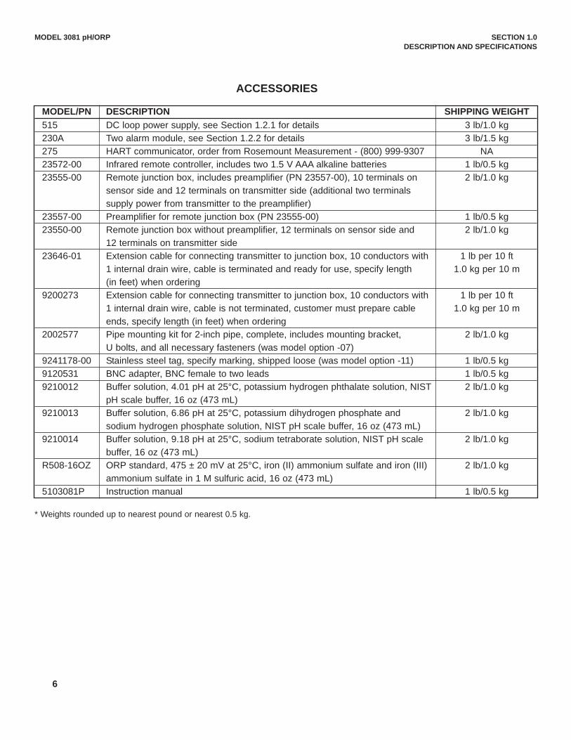
MODEL/PN DESCRIPTION SHIPPING WEIGHT515 DC loop power supply, see Section 1.2.1 for details 3 lb/1.0 kg230A Two alarm module, see Section 1.2.2 for details 3 lb/1.5 kg275 HART communicator, order from Rosemount Measurement - (800) 999-9307 NA23572-00 Infrared remote controller, includes two 1.5 V AAA alkaline batteries 1 lb/0.5 kg23555-00 Remote junction box, includes preamplifier (PN 23557-00), 10 terminals on 2 lb/1.0 kg
sensor side and 12 terminals on transmitter side (additional two terminals supply power from transmitter to the preamplifier)
23557-00 Preamplifier for remote junction box (PN 23555-00) 1 lb/0.5 kg23550-00 Remote junction box without preamplifier, 12 terminals on sensor side and 2 lb/1.0 kg
12 terminals on transmitter side23646-01 Extension cable for connecting transmitter to junction box, 10 conductors with 1 lb per 10 ft
1 internal drain wire, cable is terminated and ready for use, specify length 1.0 kg per 10 m(in feet) when ordering
9200273 Extension cable for connecting transmitter to junction box, 10 conductors with 1 lb per 10 ft1 internal drain wire, cable is not terminated, customer must prepare cable 1.0 kg per 10 mends, specify length (in feet) when ordering
2002577 Pipe mounting kit for 2-inch pipe, complete, includes mounting bracket, 2 lb/1.0 kgU bolts, and all necessary fasteners (was model option -07)
9241178-00 Stainless steel tag, specify marking, shipped loose (was model option -11) 1 lb/0.5 kg9120531 BNC adapter, BNC female to two leads 1 lb/0.5 kg9210012 Buffer solution, 4.01 pH at 25°C, potassium hydrogen phthalate solution, NIST 2 lb/1.0 kg
pH scale buffer, 16 oz (473 mL)9210013 Buffer solution, 6.86 pH at 25°C, potassium dihydrogen phosphate and 2 lb/1.0 kg
sodium hydrogen phosphate solution, NIST pH scale buffer, 16 oz (473 mL)9210014 Buffer solution, 9.18 pH at 25°C, sodium tetraborate solution, NIST pH scale 2 lb/1.0 kg
buffer, 16 oz (473 mL)R508-16OZ ORP standard, 475 ± 20 mV at 25°C, iron (II) ammonium sulfate and iron (III) 2 lb/1.0 kg
ammonium sulfate in 1 M sulfuric acid, 16 oz (473 mL)5103081P Instruction manual 1 lb/0.5 kg
ACCESSORIES
* Weights rounded up to nearest pound or nearest 0.5 kg.

2.1 UNPACKING AND INSPECTIONInspect the shipping container. If it is damaged, contact the shipper immediately for instructions. Save the box. If there isno apparent damage, remove the transmitter. Be sure all items shown on the packing list are present. If items are miss-ing, immediately notify Rosemount Analytical. Save the shipping container and packaging. They can be reused if it is later necessary to return the transmitter to the fac-tory.
2.2 PRE-INSTALLATION SETUP2.2.1 Transmitter Default SettingsTwo jumpers and a switch may need to be changed from the factory default settings before installing the transmitter. Thesettings tell the transmitter the type of temperature element in the sensor, whether the reference electrode is high or lowimpedance, and the location of the preamplifier. The factory default settings are given below.
default settingtemperature element Pt 100 RTDreference impedance lowpreamplifier location in transmitter
If your sensor or system is different, the transmitter settings must be changed. If you do not know the type of temperatureelement in the sensor, whether the reference electrode impedance is high or low, or the location of the preamplifier, referto Sections 2.2.2, 2.2.3, and 2.2.4.
2.2.2 Temperature ElementThe Model 3081 pH/ORP transmitter is compatible with sensors having Pt 100, Pt 1000, or 3K Balco RTDs. pH and ORPsensors manufactured by Rosemount Analytical contain either a Pt 100 or a 3K Balco RTD. Sensors from other manufac-turers may have a Pt 1000 RTD. For Rosemount Analytical sensors, the type of temperature element in the sensor is print-ed on the metalized tag attached to the sensor cable. If the label is missing or unreadable, determine the type of RTD bymeasuring the resistance across the RTD IN and RTD RTN leads. For the majority of sensors manufactured by RosemountAnalytical, the RTD IN lead is red and the RTD RTN lead is white. For the Model 399-33 ORP sensor, the leads are blackand white. The Model 328A sensor has no RTD. The Model 320HP system has a readily identifiable separate temperatureelement. Resistance at room temperature for common RTDs is given in the table.
If the resistance is... the temperature element is a about 110 ohms Pt 100 RTDabout 1100 ohms Pt 1000 RTDabout 3000 ohms 3K Balco RTD
2.2.3 Reference Electrode ImpedanceThe standard silver-silver chloride reference electrode used in most industrial and laboratory pH electrodes is low imped-ance. EVERY pH and ORP sensor manufactured by Rosemount Analytical has a low impedance reference. Certain spe-cialized applications require a high impedance reference electrode. The transmitter must be programmed to recognize thehigh impedance reference.
MODEL 3081 pH/ORP SECTION 2.0INSTALLATION
SECTION 2.0INSTALLATION
2.1 Unpacking and Inspection2.2 Pre-Installation Set Up2.3 Orienting the Display Board2.4 Mechanical Installation2.5 Power Supply/Current Loop
7

MODEL 3081 pH/ORP SECTION 2.0INSTALLATION
8
FIGURE 2-1. Model 3081 pH/ORP Transmitter - Exploded Drawing of Circuit Board Stack
2.2.4 Preamplifier LocationpH sensors produce a high impedance voltage signal that must be preamplified before use. The signal can be preampli-fied before it reaches the transmitter or it can be preamplified in the transmitter. To work properly, the transmitter must knowwhere preamplification occurs. Although ORP sensors produce a low impedance signal, the voltage from an ORP sensoris amplified the same way as a pH signal.
If the sensor is wired to the transmitter through a junction box, the preamplifier is ALWAYS in either the junction box or thesensor. Junction boxes can be attached to the sensor or installed some distance away. If the junction box is not attachedto the sensor, it is called a remote junction box. In most junction boxes used with the Model 3081 pH/ORP, a flat, blackplastic box attached to the same circuit board as the terminal strips houses the preamplifier. The preamplifier housing inthe 381+ sensor is crescent shaped.
If the sensor is wired directly to the transmitter, the preamplifier can be in the sensor or in the transmitter. If the sensorcable has a GREEN wire, the preamplifier is in the sensor. If there is no green wire, the sensor cable will contain a coax-ial cable. A coaxial cable is an insulated wire surrounded by a braided metal shield. Depending on the sensor model, thecoaxial cable terminates in either a BNC connector or in a separate ORANGE wire and CLEAR shield.
2.2.5 Changing Switch and Jumper PositionsIf the sensor and installation does not match the transmitter default settings in Section 2.2.1, change the settings to thecorrect values.1. Refer to Figure 2-1.2. Loosen the cover lock nut until the tab disengages from the front cover. Unscrew the cover.3. Remove the three bolts holding the circuit board stack. 4. Lift out the display board. Do not disconnect the ribbon cable between it and the CPU board. The CPU and analog
boards are joined by a pin and socket connector along the bottom edge of the boards. Carefully disengage the CPUboard from the analog board. The analog board will remain attached to the transmitter body.

9
5. Set the jumpers and the slide switch on the analog board. Refer to Figure 2-2.a. Temperature element jumper.
Jumper position Temperature element
JP-1 Pt 1000 RTD
JP-2 Pt 100 RTD
JP-3 3K Balco RTD
b. Reference impedance jumper.
Jumper position Reference impedance
JP-6 low
JP-7 high
c. Reference impedance jumper JP-5.
Jumper position Reference impedance
Pin 4 only low
Pin 3 and Pin 4 high
d. Preamplifier location selection switch.
Move slider toward Preamplifier location
edge of board sensor or junction box
center of board transmitter
MODEL 3081 pH/ORP SECTION 2.0INSTALLATION
FIGURE 2-2. Model 3081 pH/ORP Transmitter Analog Board
DWG. NO. REV.
40308110 H
The transmitter must also be programmed to recognize theRTD. If pH is being measured, see Section 8.5. If ORP isbeing measured, see Section 10.5.
If sensor diagnostics are to be used with a high impedancereference electrode, the high impedance must be identifiedin the diagnostics setup program. See Section 8.4 for pHmeasurements. See Section 10.4 for ORP measurements.
Leave jumper connected on Pin 4 only, unless a highimpedance reference is used. (NOTE: all standard sen-sors use low impedance references).

10
MODEL 3081 pH/ORP SECTION 2.0INSTALLATION
6. There are more jumpers on the CPUboard. Refer to Figure 2-3. Thesejumpers are factory set and should NOTneed to be moved. This step is for trou-bleshooting purposes only.
Verify that jumpers JP-1, JP-3, and JP-4on the CPU board are in the positionsshown in Figure 2-3. For installationswhere 50 Hz ac power is present, closingJP-3 may improve immunity of the trans-mitter to noise.
7. To reassemble the stack, place the dis-play board on the CPU board. Be surethe display board is properly oriented.The small window (the infrared detectorfor the remote controller) marks the top ofthe board. Insert the three bolts throughthe holes. Align the bolts with the stand-offs on the analog board and position thedisplay and CPU boards on the analogboard. If the boards are properly aligned,the bolts will drop in place. Press alongthe bottom of the stack to seat the pinand socket connector. Tighten the bolts.
8. Replace the end cap and lock nut.
2.3 ORIENTING THE DISPLAY BOARDThe display board can be rotated 90 degrees, clockwise or counterclockwise, from the original position. To reposition thedisplay:
1. Loosen the cover lock nut until the tab disengages from the circuit end cap. Unscrew the cap.
2. Remove the three bolts holding the circuit board stack.
3. Lift and rotate the display board 90 degrees, clockwise or counterclockwise, into the desired position.
4. Position the display board on the stand offs. Replace and tighten the bolts.
5. Replace the circuit end cap.
2.4 MECHANICAL INSTALLATION2.4.1 General information1. The transmitter tolerates harsh environments. For best results, install the transmitter in an area where temperature
extremes, vibrations, and electromagnetic and radio frequency interference are minimized or absent.
2. To prevent unintentional exposure of the transmitter circuitry to the plant environment, keep the security lock in placeover the circuit end cap. To remove the circuit end cap, loosen the lock nut until the tab disengages from the end cap,then unscrew the cover.
3. The transmitter has two 3/4-inch conduit openings, one on each side of the housing. Run sensor cable through the leftside opening (as viewed from the wiring terminal end of the transmitter) and run power/current loop wiring through theright side opening.
FIGURE 2-3. Model 3081 pH/ORP Transmitter CPU Board
DWG. NO. REV.
40008125 A

11
MODEL 3081 pH/ORP SECTION 2.0INSTALLATION
FIGURE 2-4. Mounting the Model 3081 pH/ORP Transmitter on a Flat Surface
MILLIMETERINCH
4. Use weathertight cable glands to keep moisture out of the transmitter.5. If conduit is used, plug and seal the connections at the transmitter housing to prevent moisture from getting inside the
transmitter.NOTE
Moisture accumulating in the transmitter housing can affect the performance of the trans-mitter and may void the warranty.
6. If the transmitter is installed some distance from the sensor, a remote junction box with preamplifier in the junction boxor in the sensor may be necessary. Consult the sensor instruction manual for maximum cable lengths.
2.4.2 Mounting on a Flat Surface.See Figure 2-4.

12
MODEL 3081 pH/ORP SECTION 2.0INSTALLATION
FIGURE 2-5. Using the Pipe Mounting Kit to Attach the Model 3081 pH/ORP Transmitter to a Pipe
MILLIMETERINCH
2.4.3 Pipe Mounting.See Figure 2-5. The pipe mounting kit (PN 2002577) accommodates 1-1/2 to 2 in. pipe.
DWG. NO. REV.
40308104 G
DWG. NO. REV.
40308103 C

13
MODEL 3081 pH/ORP SECTION 2.0INSTALLATION
2.5 POWER SUPPLY/CURRENT LOOP2.5.1 Power Supply and Load Requirements.Refer to Figure 2-6.The minimum power supply voltage is 12.5 Vdc andthe maximum is 42.4 Vdc. The top line on the graphgives the voltage required to maintain at least 12.5Vdc at the transmitter terminals when the output sig-nal is 22 mA. The lower line is the supply voltagerequired to maintain a 30 Vdc terminal voltage whenthe output signal is 22 mA.The power supply must provide a surge currentduring the first 80 milliseconds of start-up. For a24 Vdc power supply and a 250 ohm load resistorthe surge current is 40 mA. For all other supplyvoltage and resistance combinations the surgecurrent is not expected to exceed 70 mA.For digital (HART or AMS) communications, theload must be at least 250 ohms. To supply the 12.5Vdc lift off voltage at the transmitter, the power sup-ply voltage must be at least 18 Vdc.For intrinsically safe operation the supply voltage should not exceed 42.4 Vdc.
FIGURE 2-6. Load/Power Supply Requirements
FIGURE 2-7. Power Supply/Current Loop Wiring
2.5.2 Power Supply-Current LoopWiring. Refer to Figure 2-7.Run the power/signal wiring throughthe opening nearest terminals 15 and16. Use shielded cable and ground theshield at the power supply. To groundthe transmitter, attach the shield to thegrounding screw on the inside of thetransmitter case. A third wire can alsobe used to connect the transmittercase to earth ground.
NOTEFor optimum EMI/RFIimmunity, the power sup-ply/output cable shouldbe shielded andenclosed in an earth-grounded metal conduit.
Do not run power supply/signal wiringin the same conduit or cable tray withAC power lines or with relay actuatedsignal cables. Keep power supply/ sig-nal wiring at least 6 ft (2 m) away fromheavy electrical equipment. An additional 0-1 mA current loop isavailable between TB-14 and TB-15. A1 mA current in this loop signifies asensor fault. See Figure 4-3 for wiringinstructions. See Section 8.3 or 10.3and Section 12.0 for more informationabout sensor faults.
DWG. NO. REV.
40308122 B

14
MODEL 3081 pH/ORP SECTION 3.0 WIRING
SECTION 3.0WIRING
3.1 GENERAL INFORMATIONpH and ORP sensors manufactured by Rosemount Analytical can be wired to the Model 3081 pH/ORP transmitter in threeways:1. directly to the transmitter,2. to a sensor-mounted junction box and then to the transmitter,3. to a remote junction box and then from the remote junction box to the transmitter.The pH (or ORP) signal can also be preamplified in one of four places.1. in the sensor,2. in a junction box mounted on the sensor, 3. in a remote junction box. 4. at the transmitter.Figure 3-1 illustrates the various arrangements.
3.1 General Information3.2 Wiring Diagrams
FIGURE 3-1. Wiring and Preamplifier Configurations for pH and ORP Sensors. The asterisk identifies the location of the preamplifier. In (a) and (b) the sensor is wired directly to the transmitter. The signal isamplified at the sensor (a) or at the transmitter (b). In (c) the sensor is wired through a sensor-mounted junction box to the trans-mitter. The preamplifier is in the sensor-mounted junction box. In (d) and (e) the sensor is wired through a remote junction box tothe transmitter. The preamplifier is located in the sensor (d) or the junction box (e).

MODEL 3081 pH/ORP SECTION 3.0 WIRING
3.2 WIRING DIAGRAMS FOR pH and ORP SENSORSRefer to Tables 3-1 through 3-12 to locate the appropriate wire function and wiring diagram. There is a separate table foreach model. The sensor models having the highest number appear first. If you do not know the model number of thesensor, refer to the flow charts on pages 28 through 30. Only the model option numbers needed to select the cor-rect wiring diagram are shown. Other numbers are not shown. For all other sensors, see sensor manual.
Table 3-1. Wiring Diagrams for Model 399 sensors
Sensor Junction Box Preamplifier RTD Wire Function Wiring Diagram 399-02 none in transmitter 3K Balco** Figure 3-2 Figure 3-4
399-02 remote in remote junction box 3K Balco** Figure 3-2 Figure 3-5
399-09* none in transmitter Pt 100 Figure 3-2 Figure 3-4
399-09* remote in remote junction box Pt 100 Figure 3-2 Figure 3-5
399-09-62 none in transmitter Pt 100 Figure 3-3 Figure 3-4
399-09-62 remote in remote junction box Pt 100 Figure 3-3 Figure 3-5
399-33 (ORP only) none in transmitter Pt 100 Figure 3-21 Figure 3-22
Table 3-2 Wiring Diagrams for Model 397 Sensors
Sensor Junction Box Preamplifier RTD Wire Function Wiring Diagram397-50 none in transmitter 3K Balco** Figure 3-6 Figure 3-8
397-50 remote in remote junction box 3K Balco** Figure 3-6 Figure 3-9
397-54* none in transmitter Pt 100 Figure 3-6 Figure 3-8
397-54* remote in remote junction box Pt 100 Figure 3-6 Figure 3-9
397-54-62 none in transmitter Pt 100 Figure 3-7 Figure 3-8
397-54-62 remote in remote junction box Pt 100 Figure 3-7 Figure 3-9
Table 3-3 Wiring Diagrams for Model 396R Sensors
Sensor Junction Box Preamplifier RTD Wire Function Wiring Diagram396R-50 remote in remote junction box 3K Balco** Figure 3-10 Figure 3-12
396R-50 none in transmitter 3K Balco** Figure 3-10 Figure 3-11
396R-50-60 sensor-mounted in sensor-mounted junction box 3K Balco** Figure 3-6 Figure 3-9
396R-54 none in transmitter Pt 100 Figure 3-10 Figure 3-11
396R-54 remote in remote junction box Pt 100 Figure 3-10 Figure 3-12
396R-54-60 sensor-mounted in sensor-mounted junction box Pt 100 Figure 3-7 Figure 3-9
396R-54-61 sensor-mounted in sensor-mounted junction box Pt 100 Figure 3-10 Figure 3-12
* Sensors have a BNC connector that the Model 3081 pH/ORP transmitter does not accept. Cut off the BNC and terminatethe coaxial cable as shown in Figure 3-23. Alternatively, use a BNC adapter (PN 9120531).
** Set the RTD jumper to the 3K position (see Section 2.2). Also, program the transmitter to recognize the 3K RTD (seeSection 8.5 for pH or 10.5 for ORP).
15

16
MODEL 3081 pH/ORP SECTION 3.0 WIRING
Table 3-4 Wiring Diagrams for Model 396P Sensors
Sensor Junction Box Preamplifier RTD Wire Function Wiring Diagram396P-01-55 none in sensor Pt 100 Figure 3-13 Figure 3-14
396P-01-55 remote in sensor Pt 100 Figure 3-13 Figure 3-14
396P-02-50 none in transmitter 3K Balco** Figure 3-10 Figure 3-11
396P-02-50 remote in remote junction box 3K Balco** Figure 3-10 Figure 3-12
396P-02-54 none in transmitter Pt 100 Figure 3-10 Figure 3-11
396P-02-54 remote in remote junction box Pt 100 Figure 3-10 Figure 3-12
396P-02-55 none in transmitter Pt 100 Figure 3-10 Figure 3-11
396P-02-55 remote in remote junction box Pt 100 Figure 3-10 Figure 3-12
Table 3-5 Wiring Diagrams for Model 396 Sensor
Sensor Junction Box Preamplifier RTD Wire Function Wiring Diagram396-50* none in transmitter 3K Balco** Figure 3-6 Figure 3-8
396-50* remote in remote junction box 3K Balco** Figure 3-6 Figure 3-9
396-54* none in transmitter Pt 100 Figure 3-6 Figure 3-8
396-54* remote in remote junction box Pt 100 Figure 3-6 Figure 3-9
396-54-62 none in transmitter Pt 100 Figure 3-7 Figure 3-8
396-54-62 remote in remote junction box Pt 100 Figure 3-7 Figure 3-9
Table 3-6 Wiring Diagrams for Model 389 Sensors
Sensor Junction Box Preamplifier RTD Wire Function Wiring Diagram389-02-50* none in transmitter 3K Balco** Figure 3-6 Figure 3-8
389-02-50* remote in remote junction box 3K Balco** Figure 3-6 Figure 3-9
389-02-54* none in transmitter Pt 100 Figure 3-6 Figure 3-8
389-02-54* remote in remote junction box Pt 100 Figure 3-6 Figure 3-9
389-02-54-62 none in transmitter Pt 100 Figure 3-7 Figure 3-8
389-02-54-62 remote in remote junction box Pt 100 Figure 3-7 Figure 3-9
* Sensors have a BNC connector that the Model 3081 pH/ORP transmitter does not accept. Cut off the BNC and terminatethe coaxial cable as shown in Figure 3-23. Alternatively, use a BNC adapter (PN 9120531).
** Set the RTD jumper to the 3K position (see Section 2.2). Also, program the transmitter to recognize the 3K RTD (seeSection 8.5 for pH or 10.5 for ORP).

17
MODEL 3081 pH/ORP SECTION 3.0 WIRING
Table 3-7 Wiring Diagrams for Model 385+ Sensors
Sensor Junction Box Preamplifier RTD Wire Functions Wiring Diagram385+ -02 sensor-mounted in sensor-mounted junction box Pt 100 Figure 3-15 Figure 3-16385+ -03 none in sensor Pt 100 Figure 3-13 Figure 3-14385+ -03 remote in sensor Pt 100 Figure 3-13 Figure 3-14385+ -04 none in transmitter Pt 100 Figure 3-10 Figure 3-11385+ -04 remote in remote junction box Pt 100 Figure 3-10 Figure 3-12
Table 3-8 Wiring Diagrams for Model 381+ Sensors
Sensor Junction Box Preamplifier RTD Wire Functions Wiring Diagram381+ -40-55 none in sensor Pt 100 Figure 3-13 Figure 3-14381+ -43-55 none in sensor Pt 100 Figure 3-13 Figure 3-14381+ -40-55 remote in sensor Pt 100 Figure 3-13 Figure 3-14381+ -43-55 remote in sensor Pt 100 Figure 3-13 Figure 3-14381+ -41-52 none in transmitter Pt 100 Figure 3-10 Figure 3-11381+ -41-52 remote in remote junction box Pt 100 Figure 3-10 Figure 3-12
Table 3-9 Wiring Diagrams for Model 381pHE and 381pH Sensors
Sensor Junction Box Preamplifier RTD Wire Functions Wiring Diagram381pH-30-41-52* none in transmitter 3K Balco** Figure 3-2 Figure 3-4381pH-30-41-52* remote in remote junction box 3K Balco** Figure 3-2 Figure 3-5381pH-30-42-52 none in transmitter 3K Balco** Figure 3-3 Figure 3-4381pH-30-42-52 remote in remote junction box 3K Balco** Figure 3-3 Figure 3-5381pHE-31-41-52* none in transmitter Pt 100 Figure 3-2 Figure 3-4381pHE-31-41-52* remote in remote junction box Pt 100 Figure 3-2 Figure 3-5381pHE-31-42-52 none in transmitter Pt 100 Figure 3-3 Figure 3-4381pHE-31-42-52 remote in remote junction box Pt 100 Figure 3-3 Figure 3-5
Table 3-10 Wiring Diagrams for Model 328A Sensor
Sensor Junction Box Preamplifier RTD Wire Functions Wiring Diagram328A none in transmitter none Figure 3-17 Figure 3-18
Table 3-11 Wiring Diagrams for Model 320HP Sensor
Sensor Junction Box Preamplifier RTD Wiring Diagram320HP-10-55 on mounting plate in transmitter Pt 100 Figure 3-19320HP-10-58 on mounting plate in junction box attached to mounting plate Pt 100 Figure 3-20
* Sensors have a BNC connector that the Model 3081 pH/ORP transmitter does not accept. Cut off the BNC and terminate the coaxi-al cable as shown in Figure 3-23. Alternatively, use a BNC adapter (PN 9120531).
** Set the RTD jumper to the 3K position (see Section 2.2). Also, program the transmitter to recognize the 3K RTD (see Section 8.5for pH or 10.5 for ORP).
18
MODEL 3081 pH/ORP SECTION 3.0 WIRING
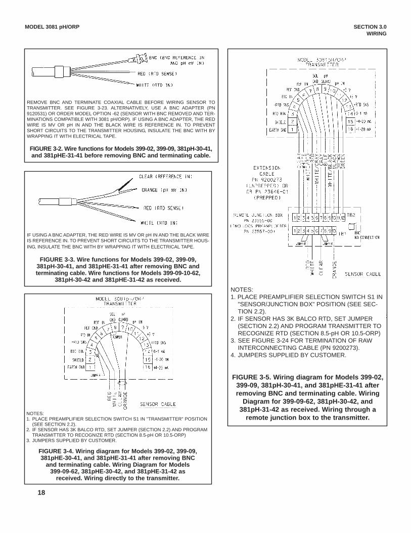
REMOVE BNC AND TERMINATE COAXIAL CABLE BEFORE WIRING SENSOR TOTRANSMITTER. SEE FIGURE 3-23. ALTERNATIVELY, USE A BNC ADAPTER (PN9120531) OR ORDER MODEL OPTION -62 (SENSOR WITH BNC REMOVED AND TER-MINATIONS COMPATIBLE WITH 3081 pH/ORP). IF USING A BNC ADAPTER, THE REDWIRE IS MV OR pH IN AND THE BLACK WIRE IS REFERENCE IN. TO PREVENTSHORT CIRCUITS TO THE TRANSMITTER HOUSING, INSULATE THE BNC WITH BYWRAPPING IT WITH ELECTRICAL TAPE.
FIGURE 3-2. Wire functions for Models 399-02, 399-09, 381pH-30-41,and 381pHE-31-41 before removing BNC and terminating cable.
IF USING A BNC ADAPTER, THE RED WIRE IS MV OR pH IN AND THE BLACK WIREIS REFERENCE IN. TO PREVENT SHORT CIRCUITS TO THE TRANSMITTER HOUS-ING, INSULATE THE BNC WITH BY WRAPPING IT WITH ELECTRICAL TAPE.
FIGURE 3-3. Wire functions for Models 399-02, 399-09,381pH-30-41, and 381pHE-31-41 after removing BNC andterminating cable. Wire functions for Models 399-09-10-62,
381pH-30-42 and 381pHE-31-42 as received.
NOTES:1. PLACE PREAMPLIFIER SELECTION SWITCH S1 IN "TRANSMITTER" POSITION
(SEE SECTION 2.2).2. IF SENSOR HAS 3K BALCO RTD, SET JUMPER (SECTION 2.2) AND PROGRAM
TRANSMITTER TO RECOGNIZE RTD (SECTION 8.5-pH OR 10.5-ORP)3. JUMPERS SUPPLIED BY CUSTOMER.
FIGURE 3-4. Wiring diagram for Models 399-02, 399-09,381pHE-30-41, and 381pHE-31-41 after removing BNC
and terminating cable. Wiring Diagram for Models399-09-62, 381pHE-30-42, and 381pHE-31-42 as
received. Wiring directly to the transmitter.
NOTES:1. PLACE PREAMPLIFIER SELECTION SWITCH S1 IN
"SENSOR/JUNCTION BOX" POSITION (SEE SEC-TION 2.2).
2. IF SENSOR HAS 3K BALCO RTD, SET JUMPER(SECTION 2.2) AND PROGRAM TRANSMITTER TORECOGNIZE RTD (SECTION 8.5-pH OR 10.5-ORP)
3. SEE FIGURE 3-24 FOR TERMINATION OF RAWINTERCONNECTING CABLE (PN 9200273).
4. JUMPERS SUPPLIED BY CUSTOMER.
FIGURE 3-5. Wiring diagram for Models 399-02,399-09, 381pH-30-41, and 381pHE-31-41 afterremoving BNC and terminating cable. Wiring
Diagram for 399-09-62, 381pH-30-42, and381pH-31-42 as received. Wiring through a
remote junction box to the transmitter.

19
MODEL 3081 pH/ORP SECTION 3.0 WIRING
REMOVE BNC AND TERMINATE COAXIAL CABLE BEFORE WIRING SENSOR TOTRANSMITTER. SEE FIGURE 3-23. ALTERNATIVELY, USE A BNC ADAPTER (PN9120531) OR ORDER MODEL OPTION -62 (SENSOR WITH BNC REMOVED ANDTERMINATIONS COMPATIBLE WITH 3081 pH/ORP). IF USING A BNC ADAPTER,THE RED WIRE IS MV OR pH IN AND THE BLACK WIRE IS REFERENCE IN. TOPREVENT SHORT CIRCUITS TO THE TRANSMITTER HOUSING, INSULATE THEBNC WITH BY WRAPPING IT WITH ELECTRICAL TAPE.
FIGURE 3-6. Wire functions for Models 397-50, 397-54, 396-50,396-54, 396R-50-60, 396R-54-60, 389-02-50, and 389-02-54
before removing BNC and terminating cable.
IF USING A BNC ADAPTER, THE RED WIRE IS MV OR pH IN AND THE BLACK WIREIS REFERENCE IN. TO PREVENT SHORT CIRCUITS TO THE TRANSMITTERHOUSING, INSULATE THE BNC WITH BY WRAPPING IT WITH ELECTRICAL TAPE.
FIGURE 3-7. Wire functions for Models 397-50, 397-54, 396-50,396-54, 396R-50-60, 396R-54-60, 389-02-50, and 389-02-54 after
removing BNC and terminating cable. Wire functions forModels 397-54-62, 396-54-62, and 389-02-54-62 as received.
NOTES:1. PLACE PREAMPLIFIER SELECTION SWITCH S1 IN "TRANSMITTER" POSITION
(SEE SECTION 2.2).2. IF SENSOR HAS 3K BALCO RTD, SET JUMPER (SECTION 2.2) AND PROGRAM
TRANSMITTER TO RECOGNIZE RTD (SECTION 8.5-pH OR 10.5-ORP)3. JUMPERS SUPPLIED BY CUSTOMER.
FIGURE 3-8. Wiring diagram for Models 397-50, 397-54, 396-50,396-54, 389-02-50, and 389-02-54 after removing BNC and termi-
nating cable. Wiring diagram for Models 397-54-62, 396-54-62, and389-02-54-62 as received. Wiring directly to the transmitter.
NOTES:1. PLACE PREAMPLIFIER SELECTION SWITCH S1 IN "SEN-
SOR/JUNCTION BOX" POSITION (SEE SECTION 2.2).2. IF SENSOR HAS 3K BALCO RTD, SET JUMPER (SECTION
2.2) AND PROGRAM TRANSMITTER TO RECOGNIZE RTD(SECTION 8.5-pH OR 10.5-ORP)
3. SEE FIGURE 3-24 FOR TERMINATION OF RAWINTERCONNECTING CABLE (PN 9200273).
4. JUMPERS SUPPLIED BY CUSTOMER.
FIGURE 3-9. Wiring diagram for Models 397-50,397-54, 396-50, 396R-50-60, 396R-54-60, 396-54,389-02-50, and 389-02-54 after removing BNC
and terminating cable. Wiring diagram forModels 397-54-62, 396-54-62, and 389-02-54-62as received. Wiring through a remote junction
box to the transmitter.
3
4
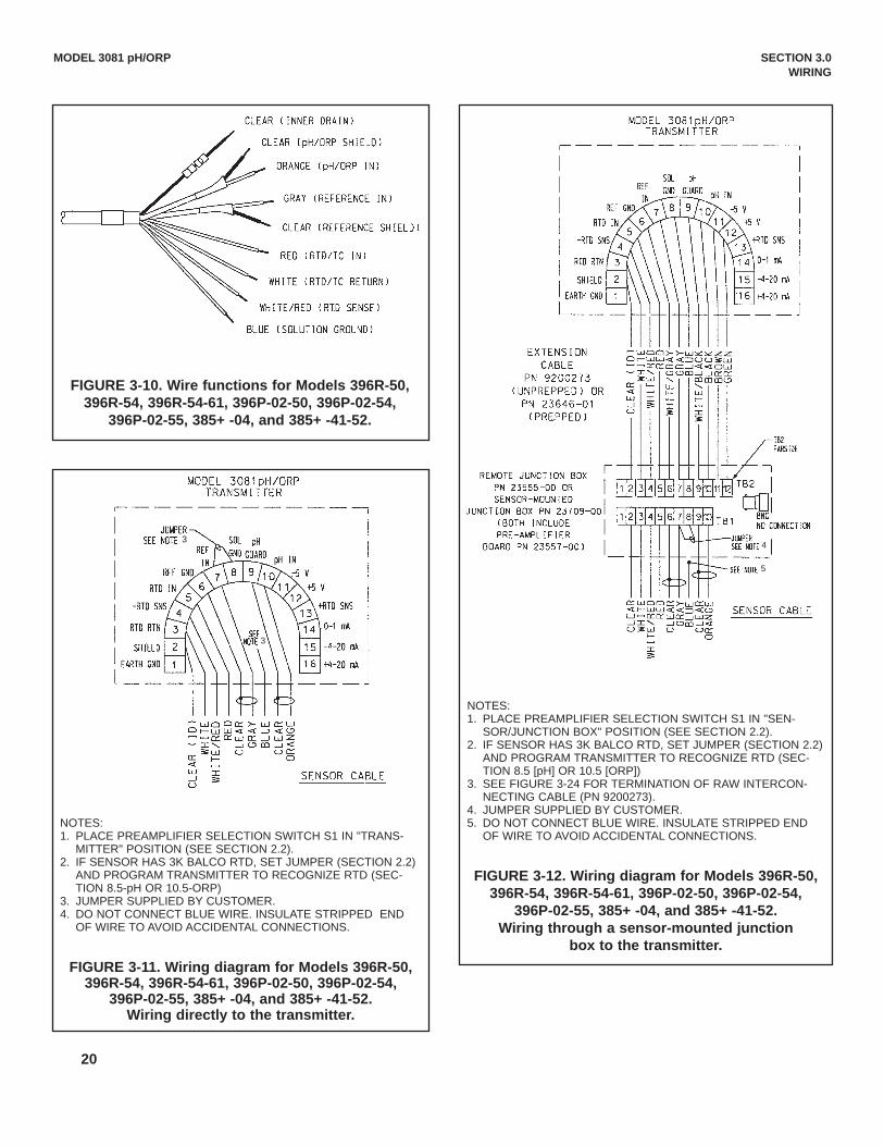
20
MODEL 3081 pH/ORP SECTION 3.0 WIRING
FIGURE 3-10. Wire functions for Models 396R-50,396R-54, 396R-54-61, 396P-02-50, 396P-02-54,
396P-02-55, 385+ -04, and 385+ -41-52.
NOTES:1. PLACE PREAMPLIFIER SELECTION SWITCH S1 IN "TRANS-
MITTER" POSITION (SEE SECTION 2.2).2. IF SENSOR HAS 3K BALCO RTD, SET JUMPER (SECTION 2.2)
AND PROGRAM TRANSMITTER TO RECOGNIZE RTD (SEC-TION 8.5-pH OR 10.5-ORP)
3. JUMPER SUPPLIED BY CUSTOMER.4. DO NOT CONNECT BLUE WIRE. INSULATE STRIPPED END
OF WIRE TO AVOID ACCIDENTAL CONNECTIONS.
FIGURE 3-11. Wiring diagram for Models 396R-50,396R-54, 396R-54-61, 396P-02-50, 396P-02-54,
396P-02-55, 385+ -04, and 385+ -41-52.Wiring directly to the transmitter.
NOTES:1. PLACE PREAMPLIFIER SELECTION SWITCH S1 IN "SEN-
SOR/JUNCTION BOX" POSITION (SEE SECTION 2.2).2. IF SENSOR HAS 3K BALCO RTD, SET JUMPER (SECTION 2.2)
AND PROGRAM TRANSMITTER TO RECOGNIZE RTD (SEC-TION 8.5 [pH] OR 10.5 [ORP])
3. SEE FIGURE 3-24 FOR TERMINATION OF RAW INTERCON-NECTING CABLE (PN 9200273).
4. JUMPER SUPPLIED BY CUSTOMER.5. DO NOT CONNECT BLUE WIRE. INSULATE STRIPPED END
OF WIRE TO AVOID ACCIDENTAL CONNECTIONS.
FIGURE 3-12. Wiring diagram for Models 396R-50,396R-54, 396R-54-61, 396P-02-50, 396P-02-54,
396P-02-55, 385+ -04, and 385+ -41-52.Wiring through a sensor-mounted junction
box to the transmitter.
4
5
3
3

21
MODEL 3081 pH/ORP SECTION 3.0 WIRING
FIGURE 3-13. Wire functions for Models 396P-01-55, 385+ -03,381+ -40-55, and 381+ -43-55.
NOTES:1. PLACE PREAMPLIFIER SELECTION SWITCH S1 IN
"SENSOR/JUNCTION BOX" POSITION (SEE SECTION 2.2).2. TO EXTEND CABLE LENGTH, USE JUNCTION BOX PN 23550-
00 WITH EXTENSION CABLE PN 23646-01 (FINISHED) OR PN9200273 (UNFINISHED). WIRE THROUGH TERMINALS POINTTO POINT. SEE FIGURE 3-24 FOR TERMINATION OF RAWCABLE PN 9200273.
FIGURE 3-14. Wiring diagram for Models 396P-01-55,385+ -03, 381+ -40-55, and 381+ -43-55.

22
MODEL 3081 pH/ORP SECTION 3.0 WIRING
FIGURE 3-15. Wire functions for Model 385+ -02.
NOTES:1. PLACE PREAMPLIFIER SELECTION SWITCH S1 IN "SENSOR/JUNCTION BOX" POSITION (SEE
SECTION 2.2).2. SEE FIGURE 3-24 FOR TERMINATION OF RAW INTERCONNECTING CABLE (PN 9200273).3. JUMPER SUPPLIED BY CUSTOMER.4. DO NOT CONNECT BLUE WIRE. INSULATE STRIPPED END OF WIRE TO AVOID ACCIDENTAL
CONNECTIONS.
FIGURE 3-16. Wiring diagram for Model 385+ -02.

23
MODEL 3081 pH/ORP SECTION 3.0 WIRING
NOTE: MODEL 328A-08 HAS UNDRESSED COAXIAL CABLE. SEE SENSOR INSTRUCTIONSHEET FOR CABLE PREPARATION PROCEDURE.
FIGURE 3-17. Wire functions for Model 328A-07.
NOTES:1. PLACE PREAMPLIFIER SELECTION SWITCH S1 IN "TRANS-
MITTER" POSITION (SEE SECTION 2.2).2. JUMPERS SUPPLIED BY CUSTOMER.3. MODEL 328A-08 HAS UNDRESSED COAXIAL CABLE. CABLE
MUST BE TERMINATED BEFORE WIRING SENSOR TO TRANS-MITTER. CENTRAL CONDUCTOR IS pH SIGNAL (TB-10) ANDSHIELD IS REFERENCE SIGNAL (TB-7). SEE SENSORINSTRUCTION SHEET FOR DETAILS.
4. AUTOMATIC TEMPERATURE COMPENSATION MUST BETURNED OFF. SEE SECTION 8.5.
FIGURE 3-18. Wiring diagram for Model 328A.

24
MODEL 3081 pH/ORP SECTION 3.0 WIRING
NOTES:1. PLACE PREAMPLIFIER SELECTION SWITCH S1 IN "TRANS-
MITTER" POSITION (SEE SECTION 2.2).2. TERMINALS IN JUNCTION BOX ARE NOT NUMBERED.
COUNT POSITION FROM LEFT TO RIGHT AS SHOWN INDRAWING.
3. JUMPERS SUPPLIED BY CUSTOMER.4. CUSTOMER MUST INSTALL AND WIRE pH ELECTRODE
AND TEMPERATURE SENSOR.5. SEE SENSOR MANUAL FOR PREPARATION OF EXTENSION
CABLE (PN 661-646983).6. DISCONNECT WHITE GUARD WIRE FROM TB-7 AND INSU-
LATE STRIPPED END.
FIGURE 3-19. Wiring diagram for Model 320HP-10-55.
NOTES:1. PLACE PREAMPLIFIER SELECTION SWITCH S1 IN
"SENSOR/JUNCTION BOX" POSITION (SEE SECTION 2.2).2. JUMPERS SUPPLIED BY CUSTOMER.3. CUSTOMER MUST INSTALL AND WIRE pH ELECTRODE AND TEM-
PERATURE SENSOR.4. SEE SENSOR MANUAL FOR PREPARATION OF EXTENSION
CABLE (PN 661-646983).
FIGURE 3-20 Wiring diagram for Model 320HP-10-58.

25
MODEL 3081 pH/ORP SECTION 3.0 WIRING
FIGURE 3-21. Wire Functions for Model 399-33
FIGURE 3-22. Wiring Diagram for Model 399-33

26
MODEL 3081 pH/ORP SECTION 3.0 WIRING
FIGURE 3-23. Procedure for Removing BNC Connector and Preparing Coaxial Cable
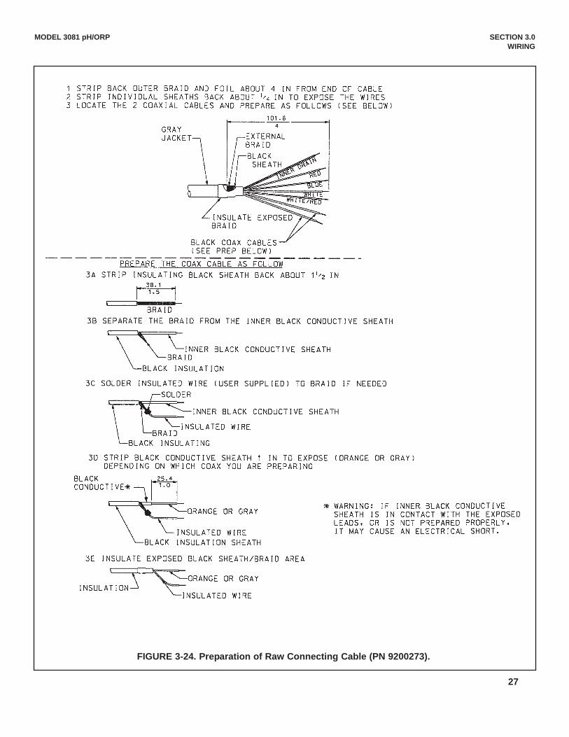
27
MODEL 3081 pH/ORP SECTION 3.0 WIRING
FIGURE 3-24. Preparation of Raw Connecting Cable (PN 9200273).

28
MODEL 3081 pH/ORP SECTION 3.0 WIRING
SEN
SOR
FLO
W C
HA
RT
(con
tinue
d on
pag
e 29
)

29
MODEL 3081 pH/ORP SECTION 3.0 WIRING
SEN
SOR
FLO
W C
HA
RT
(con
tinue
d on
pag
e 30
)
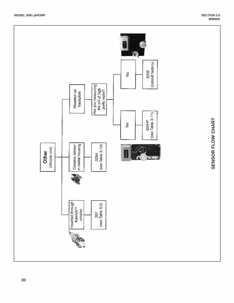
30
MODEL 3081 pH/ORP SECTION 3.0 WIRING
SEN
SOR
FLO
W C
HA
RT

31
4.1 INTRINSICALLY SAFE INSTALLATIONSThe installation wiring, operating parameters, or agency tags for intrinsically safe operation are given in Figures4-1, 4-2, and 4-3.
4.2 EXPLOSION PROOF INSTALLATIONSThe installation wiring and operating parameters for explosion proof operation are given in Figure 4-4.
MODEL 3081 pH/ORP SECTION 4.0INTRINSICALLY SAFE & EXPLOSION PROOF
SECTION 4.0INTRINSICALLY SAFE & EXPLOSION PROOF
4.1 Intrinsically Safe Installations4.2 Explosion Proof Installations
FIGURE 4-1. Intrinsically Safe BASEEFA Model 3081 Label

32
FIG
UR
E 4-
2. F
MR
C In
stal
latio
n fo
r M
odel
308
1 pH
/OR
PTr
ansm
itter

33

FIG
UR
E 4-
3. C
SAIn
stal
latio
n fo
r M
odel
308
1 pH
/OR
PTr
ansm
itter
34

35

FIG
UR
E 4-
4. E
xplo
sion
-Pro
of In
stal
latio
n fo
r M
odel
308
1 pH
/OR
PTr
ansm
itter
36

37
MODEL 3081 pH/ORP SECTION 5.0 OPERATION WITH REMOTE CONTROLLER
SECTION 5.0OPERATION WITH REMOTE CONTROLLER
CALIBRATE PROGRAM DIAGNOSE
C A L I b r A t E
E X I T N E X T E N T E R
7.00pHMV
FAULT
HOLD
♥
Appears when transmitteris in hold (see Section 8.3.2)
Appears when a disablingcondition has occurred(see Section 8.3.2)
Appears during HART and AMSoperations
Active menu: CALIBRATE,PROGRAM, or DIAGNOSE
Sub-menus, prompts, anddiagnostic messages appearhere
pH or ORP (ORP in mV)
Units of display
Available commands for sub-menu, prompt, or diagnostic
5.1 Displays5.2 Infrared Remote Controller (IRC) - Key Functions5.3 Menu Tree - pH5.4 Diagnostic Messages - pH5.5 Menu Tree - ORP5.6 Diagnostic Messages - ORP5.7 Security
FIGURE 5-2. Program Display ScreenThe program display screen appears when calibrating, programming, or reading diagnostic messages.
FIGURE 5-1. Process Display ScreenThe process display screen appears during normal operation.
pH or ORP (ORP in mV)
Temperature in °C or °F
Transmitter output signal inmA or % of full scale
5.1 DISPLAYSFigure 5-1 shows the process display screen, and Figure 5-2 shows the program display screen.

38
MODEL 3081 pH/ORP SECTION 5.0 OPERATION WITH REMOTE CONTROLLER
5.2 INFRARED REMOTE CONTROLLER (IRC) - KEY FUNCTIONSThe infrared remote controller is used to calibrate and program the transmitter and to read diagnostic messages.See Figure 5-3 for a description of the function of the keys.
Hold the IRC within 6 feet of the transmitter, and not more than 15 degrees from the center of the display window.
FIGURE 5-3. Infrared Remote Controller.
RESET - Press to end the current oper-ation and return to the process display.Changes will NOT be saved. RESETdoes not return the transmitter to factorydefault settings.
CAL - Press to access the calibratemenu.*
PROG - Press to access the programmenu.*
DIAG - Press to view diagnostic mes-sages.*
HOLD - Press to access the prompt thatturns on or off the Hold function.
Editing Keys - Use the editing keys tochange the value of a flashing display.The left and right arrow keys move thecursor one digit at a time across a num-ber. The up and down arrow keysincrease or decrease the value of theselected digit. The up and down arrowkeys also scroll the display through theitems in a list.
* Pressing CAL, PROG, or DIAG causesthe program screen to appear with theselected menu (CALIBRATE, PROGRAM,OR DIAGNOSE) showing. See Figure 5-2.The first sub-menu (or the first diagnosticmessage) also appears. Figure 5-4 showsthe complete menu tree.
ENTER - Press to advance from a sub-menu to the first prompt under the sub-menu. Pressing ENTER also stores theselected item or value in memory andadvances to the next prompt.
NEXT - Press to advance to the nextsub-menu.
EXIT - Press to end the current opera-tion. The transmitter returns to the firstprompt in the present sub-menu.Changes will NOT be saved.

39
MODEL 3081 pH/ORP SECTION 5.0 OPERATION WITH REMOTE CONTROLLER
PROGRAMCALIBRATE
OutPut
GIMP 1000 V Er 81PH.21 tEMP 25 CInPut 58.9 ShoW FLt
nonE
rIMP 10
dIAGnOStIC tEMP bUFFErdISPLAY ISOPOtntAL SIM OUtPUt
CALIbrAtE Std tEMP AdJ
tEMP 25.0
4 MA 00.00
20MA 14.00
HoLd 21.00
FAULt 22.00
dPn 0.00
tAUtO On
tMAn 25.0
tC 100-3
tYPE PH
tEMP C
OUtPUt Cur
COdE 000
bAUtO On
bUFFEr Std
tIME 10
PH 00.02
tCOEF 00.00
ISO 07.00
Snr 07.00
tESt 12.00rOFFSt 060
dIAG OFF
IMPtC ON
GWH 1000
GFH 1500
GWL 020
GFL 010
CAL 000
rEF LO
rFH 140
rWH 040
rWL 000
rFL 000
CAL bF1
bF 1
bF1 4.01
CAL bF2
bF 2
bF2 10.01
DIAGNOSE
Std 7.00
SLOPE 59.01
MENU
Sub-menu
PROMPT
Diag Message
FIGURE 5-4. Menu Tree for pH
5.3 MENU TREE - pHThe Model 3081 pH transmitter has three menus: CALIBRATE, PROGRAM, and DIAGNOSE. Under the Calibrate andProgram menus are several sub-menus. For example, under CALIBRATE, the sub-menus are CALIbrAtE, Std (stan-dard), and tEMP AdJ (temperature adjust). Under each sub-menu are prompts. For example, under Std, the promptsare Std xx.xx and slope xx.xx. The DIAGNOSE menu lets the user view diagnostic messages. Figure 5-4 shows thecomplete menu tree.
5.4 DIAGNOSTIC MESSAGES - pHWhenever a warning or fault limit has been exceeded, the transmitter displays diagnostic messages to aid in trou-bleshooting. Diagnostic messages appear in the same area as the temperature/output readings in the process displayscreen (see Figure 5-1). The display alternates between the regular display and the diagnostic message. Figure 5-4shows the diagnostic fault messages for pH.If more than one warning or fault message has been generated, the messages appear alternately. See Section 12.0, Troubleshooting, for the meanings of the fault and warning messages.

40
5.5 MENU TREE - ORPThe Model 3081 ORP transmitter has three menus: CALIBRATE, PROGRAM, and DIAGNOSE. Under the Calibrate andProgram menus are several sub-menus. For example, under CALIBRATE, the sub-menus are Std (standard) and tEMPAdJ (temperature adjust). Under each sub-menu are prompts. For example, the Std sub-menu contains the singleprompt Std. Other sub-menus may contain more than one prompt. Figure 5-5 shows the complete menu tree.
5.6 DIAGNOSTIC MESSAGES - ORPWhenever a warning or fault limit has been exceeded, the transmitter displays diagnostic messages to aid in trou-bleshooting. Diagnostic messages appear in the same area as the temperature/output readings in the process display(Figure 5-1). The display alternates between the regular display and the diagnostic message. Figure 5-5 shows thediagnostic fault messages for ORP.If more than one warning or fault message has been generated, the messages appear alternately. See Section 12.0, Troubleshooting, for the meanings of the fault and warning messages.
MODEL 3081 pH/ORP SECTION 5.0 OPERATION WITH REMOTE CONTROLLER
MENU
Sub-menu
PROMPT
Diag Message
FIGURE 5-5. Menu Tree for ORP
PROGRAMCALIBRATE
OutPut
rIMP 10 VEr 81PH.01 ShoW FLt
nonE
dIAGnOStIC tEMP dISPLAY SIM OUtPUt
Std tEMP ADj
tEMP
4 MA -1400
20MA 1400
HoLd 21.00
FAULt 22.00
dPn 0.00
tC 100-3 tYPE ORP
tEMP C
OUtPUt CUr
COdE 000
tESt 12.00rOFFSt 060
dIAG OFF
IMPtC OFF
rEF LO
rFH 140
rWH 040
rWL 000
rFL 000
Std 1000
DIAGNOSE
1 4 00 mV

41
5.7 SECURITY5.7.1 General. Use the programmable security code to protect program and calibrationsettings from accidentally being changed. The transmitter is shipped with the security fea-ture disabled. To program a security code, refer to Section 8.6, Display Units.
5.7.2 Entering the Security Code.1. If calibration and program settings are protected with a security code, pressing PROG
or CAL on the infrared remote controller causes the Id screen to appear.
2. Use the editing keys to enter the security code. Press ENTER .
3. If the security code is correct, the first sub-menu appears. If the security code is incor-rect, the process display reappears.
5.7.3 Retrieving a Lost Security Code.1. If the security code has been forgotten, enter 555 at the Id prompt and press ENTER .
The transmitter will display the present code.
2. Press EXIT to return to the process display.
3. Press PROG or CAL . The Id screen appears.
4. Use the editing keys to enter the security code just shown; then press ENTER .
5. The first sub-menu under the selected menu will appear.
MODEL 3081 pH/ORP SECTION 5.0 OPERATION WITH REMOTE CONTROLLER
PROGRAM
I dEXIT ENTER
000

42
6.1 Note on Model 275 HART CommunicatorThe Model 275 HART Communicator is a product of Rosemount Measurement. This section contains selectedinformation on using the Model 275 with the Rosemount Analytical Model 3081 pH/ORP Transmitter. For completeinformation on the Model 275 Communicator, see the Model 275 instruction manual. For technical support on theModel 275 Communicator, call Rosemount Measurement at (800) 999-9307, within the United States. Support isavailable worldwide on the internet at http://rosemount.com.
6.2 Connecting the HART CommunicatorFigure 6-1 shows how the Model 275 HART Communicator connects to the output lines from the Model 3081pH/ORP Transmitter.
MODEL 3081 pH/ORP SECTION 6.0OPERATION WITH MODEL 275
SECTION 6.0OPERATION WITH MODEL 275
6.1 Note on Model 275 HART Communicator6.2 Connecting the HART Communicator6.3 Operation
FIGURE 6-1. Connecting the HART Communicator
4-20 mA + Digital250 ohm
Control System
Computer
Model 3081 pH Smart
Transmitter
BridgeHand Held
Communicator(“Configurator”)
CAUTION
For intrinsically safe CSA and FMwiring connections, see the Model
275 instruction manual.

43
MODEL 3081 pH/ORP SECTION 6.0OPERATION WITH MODEL 275
6.3 Operation6.3.1 Off-line and On-line OperationThe Model 275 Communicator features off-line and on-line communications. On-line means the communicator isconnected to the transmitter in the usual fashion. While the communicator is on line, the operator can view meas-urement data, change program settings, and read diagnostic messages. Off-line means the communicator is notconnected to the transmitter. When the communicator is off line, the operator can still program settings into thecommunicator. Later, after the communicator has been connected to a transmitter, the operator can transfer theprogrammed settings to the transmitter. Off-line operation permits settings common to several transmitters to beeasily stored in all of them.
6.3.2 Menu Tree Figure 6-2 shows the menu tree for the Model 3081 pH transmitter. Figure 6-3 shows the menu tree for the Model3081 ORP transmitter.
6.3.3 Fast Key Sequences.Fast key sequences are a series of key presses that begin at the on-line menu and lead directly to a given oper-ation (for example, standardize). Some useful sequences are the following:
Key Presses
1. Calibrate with buffers 2 3 1 1
2. Standardize 2 3 2 1
3. Adjust current output to 2 4match displayed value
4. Place transmitter in hold 2 5
5. Assign pH or ORP value 3 2 2to 20 mA output
6. Assign pH or ORP value 3 2 1to 4 mA output
7. View pH value 1 1 1
8. View analog output 1 2
9. View transmitter status 1 3

44
MODEL 3081 pH/ORP SECTION 6.0OPERATION WITH MODEL 275
FIGURE 6-2a. pH Menu Tree (HART)
(Figure 6-2 is continued on page 41)

45
MODEL 3081 pH/ORP SECTION 6.0OPERATION WITH MODEL 275
FIGURE 6-2b. pH Menu Tree (HART)

46
MODEL 3081 pH/ORP SECTION 6.0OPERATION WITH MODEL 275
FIGURE 6-3a. ORP Menu Tree (HART)
(Figure 6-3 is continued on page 43)

47
MODEL 3081 pH/ORP SECTION 6.0OPERATION WITH MODEL 275
FIGURE 6-3b. ORP Menu Tree (HART)

48
MODEL 3081 pH/ORP SECTION 7.0CALIBRATION OF pH MEASUREMENTS
SECTION 7.0CALIBRATION OF pH MEASUREMENTS
7.1 General7.2 Entering and Leaving the Calibrate Menu7.3 Using the Hold Function7.4 Temperature Calibration7.5 Auto Calibration7.6 Manual Calibration7.7 Making the Transmitter Reading Match a
Second pH Meter (Standardization)
7.1 GENERALThe Calibrate menu allows the user to calibrate the pH and temperature response of the sensor. The transmitter does a two-point pH calibration. Both manual and auto calibration are available. In auto calibration thetransmitter automatically stores temperature-corrected calibration data once readings have met programmed stability lim-its. In manual calibration the user enters buffer values and judges when readings are stable. The transmitter reading canalso be made to match the reading of a second pH meter. Temperature calibration is a one-point standardization against a reference thermometer. Prompts guide the user through the calibration procedures.
7.2. ENTERING AND LEAVING THE CALIBRATE MENUPress CAL on the infrared remote controller (IRC) to enter the Calibrate menu. To store new settings in memory, pressENTER . To leave the Calibrate menu without storing new values, press EXIT . Pressing EXIT with a prompt showingreturns the display to the first prompt in the sub-menu. Pressing EXIT a second time returns the transmitter to the processdisplay.If program settings are protected with a security code, pressing PROG or CAL will cause the Id screen to appear. Keyin the security code and press ENTER . The first sub-menu will appear. For more information, see Section 5.7, Security.A transmitter adjacent to the one being calibrated may pick up signals from the IRC. To avoid accidentally changing set-tings, use a different security code for each nearby transmitter. See Section 5.7, Security, and Section 8.6, Display Units,for details.
7.3 USING THE HOLD FUNCTIONDuring calibration, the sensor may be exposed to solutions having pH outside the normal range of theprocess. To prevent false alarms and possible undesired operation of chemical dosing pumps, place thetransmitter in hold during calibration. Activating hold keeps the transmitter output at the last value or sendsthe output to a previously determined value. See Section 8.3, Output Ranging, for details.
After calibration, reinstall the sensor in the process stream. Wait until readings have stabilized beforedeactivating Hold.
To activate or deactivate Hold, do the following:1. Press HOLD on the IRC.2. The HoLd prompt appears in the display. Press or to toggle the Hold function between On and OFF.3. Press ENTER to save.

49
CALIBRATE
tEMP AAdJEXIT NEXT ENTER
CALIBRATE
tEMP EXIT ENTER
025.0
MODEL 3081 pH/ORP SECTION 7.0CALIBRATION OF pH MEASUREMENTS
7.4 TEMPERATURE CALIBRATION
7.4.1 Purpose1. As discussed in Section 13.6, Glass Electrode Slope, measuring tempera-
ture is an important part of measuring pH. The accuracy of a new sensorand transmitter loop is about ±1°C, which is adequate for most applications.A new sensor seldom requires temperature calibration.
2. Calibrate the sensor/transmitter loop if . . .a. ±1°C accuracy is NOT acceptable, orb. the temperature measurement is suspected of being in error.
NOTEA transmitter adjacent to the one being calibrated may pick upsignals from the IRC. To avoid accidentally changing settings,use a different security code for each nearby transmitter. SeeSection 5.7, Security.
7.4.2 Procedure1. Place the pH sensor and a calibrated reference thermometer in an insulated
container of water at ambient temperature. Be sure the temperature ele-ment in the sensor is completely submerged by keeping the sensor tip atleast three inches below the water level. Do not let the weight of the sensorrest on the glass bulb. Stir continuously. Allow at least 20 minutes for thestandard thermometer, sensor, and water to reach constant temperature.
2. Enter the CALIBRATE menu by pressing CAL on the IRC. The CALIbrAtEsub-menu appears (pictured above left).
3. At the CALIbrAtE sub-menu, press NEXT twice. The tEMP AdJ sub-menuappears.
4. Press ENTER to display the temperature editing prompt. 5. Compare the temperature displayed by the transmitter with the temperature
measured with the reference thermometer. If the readings are different, usethe editing keys to change the flashing display to the value determined withthe reference thermometer. The reading cannot be changed by more than15°C.
6. Press ENTER . The value will be saved, and the display will return to thetEMP AdJ sub-menu.
7. To leave the CALIBRATE menu, press EXIT .8. Check linearity by measuring the temperature of water 10 to 15°C cooler
and 10 to 15°C warmer than the water used for calibration. Because of thetime required for the temperature element in the sensor to reach constanttemperature, a well-insulated container or, better, a constant temperaturebath is required for this step.

50
7.5 AUTO CALIBRATION
7.5.1 Purpose1. New sensors must be calibrated before use. Regular recalibration is also necessary.2. The use of auto calibration instead of manual calibration is strongly recommended. Auto calibra-
tion avoids common pitfalls and reduces errors.3. For more information about calibration in pH measurements and the use of buffers, refer to
Section 13.7, Buffers and Calibration.
7.5.2 What Happens During Auto Calibration?1. The transmitter displays prompts that guide the user through a two-point buffer calibration.2. The transmitter recognizes the buffers and uses the temperature-corrected pH value in the cali-
bration. The transmitter also measures noise and drift and does not accept calibration data untilreadings are stable. Stability limits are user-programmable. See Section 9.7, Buffer CalibrationParameters.
7.5.3 Use of Calibration Standards (buffers)1. A pH measurement is only as good as the calibration, and the calibration is only as good as the
buffers used. A careful buffer calibration is the first step in making an accurate pH measurement.2. Calibrate with buffers having pH values that bracket the pH of the process. For example, if the pH
is between 8 and 9, calibrate with pH 7 and 10 buffers. Commercial buffers for intermediate rangepH are readily available. Buffers outside the range pH 3.0 to pH 10.0 may not be readily availableand must be prepared by the user. Tables 8-2 and 8-3 in Section 8.7, Buffer CalibrationParameters, list the buffers that the transmitter recognizes.
3. Allow time for the sensor and buffers to reach the same temperature. If the sensor was justremoved from a process having a temperature more than 10°C different from the buffer, allow atleast 20 minutes.
4. For best results, calibrate with buffers having the same temperature as the process. If the bufferand process temperature differ by more than about 15°C an error as great as 0.1pH may result.
5. Be careful using buffers at high temperatures. Protect the solution from evaporation. Evaporationchanges the concentration of the buffer and its pH. Be sure the pH of the buffer is defined at hightemperatures. The pH of many buffers is undefined above 60°C. Finally, no matter what the tem-perature is, allow the entire measurement cell, sensor and solution, to reach constant temperaturebefore calibrating.
6. The pH of a buffer changes with temperature. Equations relating pH to temperature for commonbuffers have been programmed into the Model 3081 pH transmitter. During auto calibration, thetransmitter calculates the correct buffer value and uses it in the calibration.
7. Buffers have limited shelf lives. Do not use a buffer if the expiration date has passed. Store buffersat controlled room temperature.
8. Do not return used buffer to the stock bottle. Discard it.9. Protect buffers from excessive exposure to air. Atmospheric carbon dioxide lowers the pH of alka-
line buffers. Other trace gases commonly found in industrial environments, for example, ammoniaand hydrogen chloride, also affect the pH of buffers. Molds, from airborne spores, grow readily inneutral and slightly acidic buffers. Mold growth can substantially alter the pH of a buffer.
10. Rinse the sensor with deionized water before placing it in a buffer. Remove excess water from thesensor by gently daubing it with a clean tissue. Do not wipe the sensor. Wiping may generate astatic charge, leading to noisy readings. The static charge may take hours to dissipate. A few dropsof deionized water carried with the sensor into the buffer will not appreciably alter the pH.
MODEL 3081 pH/ORP SECTION 7.0CALIBRATION OF pH MEASUREMENTS

7.5.4 Procedure1. Refer to Section 8.7, Buffer Calibration Parameters. Verify that auto calibration is activated. Identify
the buffers being used and set the stability limits.
2. Enter the CALIBRATE menu by pressing CAL on the IRC. The CALIbrAtE sub-menu appears (pic-tured above left).
3. At the CALIbrAtE sub-menu, press ENTER . The CAL bF1 prompt appears.
4. Rinse the sensor and place it in the first buffer. Be sure the glass bulb and the temperature elementare completely submerged. Keep the sensor tip at least three inches below the liquid level. Do notlet the weight of the sensor rest on the glass bulb. Swirl the sensor to dislodge trapped bubbles. Themain display will show the measured pH based on the previous calibration.
5. Press ENTER . bF1 flashes until the measured pH meets the programmed stability limits. If the pHreading is not stable after 20 minutes, the transmitter automatically leaves the CALIBRATE menuand returns to the process mode. If this happens, consult Section 12.5, Troubleshooting, for assis-tance. Once the reading is stable, the display changes to look like the figure at the left. The flashingnumber is the nominal pH, that is, the pH of the buffer at 25°C. If the flashing number does not matchthe nominal pH, press or until the correct pH appears. Press ENTER to save the firstcalibration point.
6. The CAL bF2 prompt appears.
7. At the CAL bF2 prompt, remove the sensor from the first buffer. Rinse the sensor and place it in the sec-ond buffer. Be sure the glass bulb and the temperature element are completely submerged. Keep thesensor tip at least three inches below the liquid level. Do not let the weight of the sensor rest on theglass bulb. Swirl the sensor to dislodge trapped bubbles. The main display will show the measured pHof the buffer based on the previous calibration.
8. Press ENTER . bF2 flashes until the pH reading is stable. If the pH reading is not stable after 20minutes, the transmitter automatically leaves the CALIBRATE menu and returns to process mode.If this happens, consult Section 12.5, Troubleshooting, for assistance. Once the reading is stable,the display changes to look like the figure at the left. The flashing number is the nominal pH, that is,the pH of the buffer at 25°C. If the flashing number does not match the nominal pH, press or until the correct pH appears. Press ENTER to save the second calibration point.
9. The calibration is complete, but the transmitter remains in the CALIbrAtE sub-menu for two minutesafter ENTER is pressed.
10. Remove the sensor from the buffer and return it to the process. If the transmitter was in hold duringcalibration, wait until readings have stabilized before taking the transmitter out of hold. See Section7.3, Using the Hold Function.
11. The transmitter uses the calibration data to calculate a new slope. Refer to Section 13.7, Buffers andCalibration, for more details. If the slope is unacceptable, the calibration will not be updated, and thetransmitter will display a SLOPE Err HI or SLOPE Err LO error message. Refer to Section 12.5,Troubleshooting, for assistance.
12. To leave the CALIBRATE menu, press EXIT .
13. For quality control and troubleshooting, it is helpful to know the electrode slope. To display the slope,press CAL on the IRC. The CALIbrAtE sub-menu will appear. Press NEXT . The Std sub-menuappears. Press ENTER . The Std prompt appears. Press ENTER again and SLOPE xx.xx willappear in the display. The four digit number is the electrode slope. For a good sensor, the slope isbetween 50 and 60.
CALIBRATE
bF 22EXIT ENTER
10 .00
MODEL 3081 pH/ORP SECTION 7.0CALIBRATION OF pH MEASUREMENTS
NOTEA transmitter adjacent to the one being calibrated may pick up signals fromthe IRC. To avoid accidentally changing settings, use a different security codefor each nearby transmitter. See Section 5.7, Security.
NOTEDuring calibration, the sensor may be exposed to solutions having pH outsidethe normal range of the process. To prevent false alarms and possible unde-sired operation of chemical dosing pumps, place the analyzer in hold duringcalibration. See Section 7.3, Using the Hold Function, for details.
CALIBRATE
CAL bbF 11EXIT NEXT ENTER
CALIBRATE
CAL bbF 22EXIT ENTER
CALIBRATE
bF 11EXIT ENTER
4.00
51

52
MODEL 3081 pH/ORP SECTION 7.0CALIBRATION OF pH MEASUREMENTS
7.6.1 Purpose1. New sensors must be calibrated before use. Regular recalibration is also necessary.2. Manual calibration is an alternative to auto calibration. Because auto calibration eliminates many
common calibration errors, it is strongly recommended. 3. In auto calibration, the transmitter recognizes the buffer and uses the temperature-corrected pH
value in the calibration. The transmitter also measures noise and drift and does not accept cali-bration data until readings meet programmed limits. In manual calibration, however, the user mustjudge when readings are stable, look up the buffer value at the calibration temperature, and key inthe value.
4. Manual calibration is necessary if non-standard buffers are used for calibration. Manual calibrationis also useful in troubleshooting.
5. Because temperature readings from the pH sensor are not available during calibration, a reliablethermometer is required to complete the procedure.
7.6.2 Use of calibration standards (buffers)1. A pH measurement is only as good as the calibration, and the calibration is only as good as the
buffers. A careful buffer calibration is the first step in making an accurate pH measurement.2. Calibrate with buffers having pH values that bracket the pH of the process. For example, if the
pH is between 8 and 9, calibrate with pH 7 and 10 buffers. Commercial buffers having interme-diate range pH are readily available. Buffers outside the range pH 3.0 to pH 10.0 may not bereadily available and must be prepared by the user.
3. Allow time for the sensor and buffers to reach the same temperature. If the process temperatureis more than 10°C different from the buffer, allow at least 20 minutes.
4. For best results, calibrate with buffers having the same temperature as the process. If the bufferand process temperature differ by more than about 15°C an error as great as 0.1pH may result.
5. Be careful using buffers at high temperatures. Protect the solution from evaporation. Evaporationchanges the concentration of the buffer and its pH. Be sure the pH of the buffer is defined at hightemperatures. The pH of many buffers is undefined above 60°C. Finally, no matter what the tem-perature is, allow the entire measurement cell, sensor and solution, to reach constant tempera-ture before calibrating.
6. The pH of a buffer changes with temperature. Equations relating pH to temperature for commonbuffers have been programmed into the Model 3081 pH transmitter. During auto calibration, thetransmitter calculates the correct buffer value and uses it in the calibration. During manual cali-bration, the user must enter the correct pH value.
7. Buffers have limited shelf lives. Do not use a buffer if the expiration date has passed. Storebuffers at controlled room temperature.
8. Do not return used buffer to the stock bottle. Discard it.9. Protect buffers from excessive exposure to air. Atmospheric carbon dioxide lowers the pH of
alkaline buffers. Other trace gases commonly found in industrial environments, for example,ammonia and hydrogen chloride, also affect the pH of buffers. Molds, from airborne spores, growreadily in neutral and slightly acidic buffers. Mold growth can substantially alter the pH of a buffer.
10. Rinse the sensor with deionized water before placing it in a buffer. Remove excess water fromthe sensor by gently daubing it with a clean tissue. Do not wipe the sensor. Wiping may gener-ate a static charge, leading to noisy readings. The static charge may take hours to dissipate. Afew drops of deionized water carried with the sensor into the buffer will not appreciably alter thepH.
7.6 MANUAL CALIBRATION

53
7.6.3 Procedure1. Before starting, refer to Section 8.7, Buffer Calibration Parameters, to deactivate auto cali-
bration.
2. Enter the CALIBRATE menu by pressing CAL on the IRC. The CALIbrAtE sub-menuappears (pictured above left).
3. At the CALIbrAtE sub-menu, press ENTER . The CAL bF1 prompt appears.
4. Rinse the sensor with deionized water and place it in the first buffer along with a calibratedthermometer. Submerge the sensor tip at least three inches below the liquid level. Do not letthe weight of the sensor rest on the glass bulb. Swirl the sensor to dislodge trapped bubbles.The main display will show the measured pH based on the previous calibration.
5. Once the pH reading and temperature are stable, press ENTER . The display changes to thescreen shown at the left. Use the editing keys to change the flashing display to the pH valueof the buffer at the measurement temperature. Press ENTER to save the value as bufferbF1. The transmitter expects a reading to be entered within 20 minutes after the CAL bF1prompt appears. If ENTER is not pressed, the transmitter leaves the CALIBRATE menu andreturns to the process mode.
6. At the CAL bF2 prompt, remove the sensor from the first buffer. Rinse the sensor and ther-mometer with deionized water and place them in the second buffer. Submerge the sensor tipat least three inches below the liquid level. Do not let the weight of the sensor rest on theglass bulb. Swirl the sensor to dislodge trapped bubbles. The main display will show themeasured pH based on the previous calibration.
7. Once the pH reading and temperature are stable, press ENTER . The display changes to thescreen shown at the left. Use the editing keys to change the flashing display to the pH valueof the buffer at the measurement temperature. Press ENTER to save the value as buffer bF2. The transmitter expects a reading to be entered within 20 minutes after the CAL bF2prompt appears. If ENTER is not pressed, the transmitter leaves the CALIBRATE menu andreturns to the process mode.
8. The calibration is complete, but the transmitter remains in the CALibrATE sub-menu for twominutes after ENTER is pressed.
9. Remove the sensor from the buffer and return it to the process. If the transmitter was in holdduring calibration, wait until readings have stabilized before taking the transmitter out of hold.
10. The transmitter uses the calibration data to calculate a new slope. Refer to Section 13.7,Buffers and Calibration, for more details. If the slope is unacceptable, the calibration will notbe updated, and the transmitter will display a SLOPE Err HI or SLOPE Err LO error mes-sage. Refer to Sections 12.5 and 12.5, Troubleshooting, for assistance.
11. To leave the CALIBRATE menu, press EXIT .12. For quality control and troubleshooting, it is helpful to know the electrode slope. To display the
slope, press CAL on the IRC. The CALIbrAtE sub-menu will appear. Press NEXT . The Stdsub-menu appears. Press ENTER . The Std prompt appears. Press ENTER again andSLOPE xx.xx will appear in the display. The four digit number is the electrode slope. For agood sensor, the slope is between 50 and 60.
MODEL 3081 pH/ORP SECTION 7.0CALIBRATION OF pH MEASUREMENTS
NOTEA transmitter adjacent to the one being calibrated may pick up signals fromthe IRC. To avoid accidentally changing settings, use a different securitycode for each nearby transmitter. See Section 5.7, Security.
NOTEDuring calibration, the sensor may be exposed to solutions having pH outsidethe normal range of the process. To prevent false alarms and possible unde-sired operation of chemical dosing pumps, place the analyzer in hold duringcalibration. See Section 7.3, Using the Hold Function, for details.
CALIBRATE
CAL bbF 11EXIT NEXT ENTER
CALIBRATE
CAL bbF 22EXIT NEXT ENTER
CALIBRATE
CAL bbF 22EXIT ENTER
CALIBRATE
CAL bbF 11EXIT ENTER
4.00
10 .00

54
MODEL 3081 pH/ORP SECTION 7.0CALIBRATION OF pH MEASUREMENTS
7.7 MAKING THE TRANSMITTER READING MATCH A SECOND pHMETER (STANDARDIZATION).
7.7.1 Purpose1. This section describes how to make the transmitter reading match the reading from a
second pH meter. The measurement made with the second meter is called the standardpH (pHstd). The process of making the two readings agree is called standardization.
2. This section also describes how to enter an independently determined slope into thetransmitter.
7.7.2 What Happens During Standardization?1. The user enters the pH reading from a second meter into the transmitter. The transmitter
changes the displayed pH to the new value.
2. The transmitter converts the difference between the pH readings, ∆pH, into a voltage dif-ference. The voltage difference, ∆V, is calculated from the equation:
∆V = [0.1984 (t + 273.14)] ∆pH
where t is the temperature in °C. The voltage difference, called the reference offset, is thenadded to subsequent pH cell voltage measurements before the voltage is converted to pH.See Sections 13.5 through 13.7 for details on how the pH meter converts voltage into pHreadings.
3. Before the transmitter accepts the offset, it compares the offset with the value (rOFFSt)programmed into the transmitter in Section 8.4, Diagnostic Parameters. If the differenceexceeds rOFFSt, the transmitter will not accept the data and will not update the display tothe corrected pH.

55
MODEL 3081 pH/ORP SECTION 7.0CALIBRATION OF pH MEASUREMENTS
CALIBRATE
StdEXIT NEXT ENTER
CALIBRATE
SLOPEEXIT NEXT ENTER
CALIBRATE
StdEXIT NEXT ENTER
08.00
59.00
7.7.3 Procedure1. Enter the CALIBRATE menu by pressing CAL on the IRC. The CALibrAtE sub-menu
appears (pictured above left).
2. At the CALibrAtE sub-menu, press NEXT . The Std sub-menu appears.
3. With the Std sub-menu displayed, press ENTER . The Std prompt appears.
4. Be sure that the process pH and temperature are stable or, at worst, slowly drifting. Takea grab sample from the process stream or sample line at a point as close as possible tothe pH sensor. Note the transmitter reading (pHtrans) at the time the sample was taken.
5. Measure the pH of the sample (pHstd) using the second pH meter. For best results makethe measurement at the same temperature as the process.
6. Note the current process reading (pHcurr). Calculate the corrected reading from the equa-tion:
pHcorr = pHcurr + (pHstd - pHtrans)
where pHcorr is the corrected pH value, pHcurr is the current process reading, pHstd is thepH measured using the standard instrument, and pHtrans is the pH measured by the trans-mitter when the sample was taken. Use the editing keys to change the flashing display topHcorr calculated above. Press ENTER to save the corrected pH.
7. The transmitter converts the difference between pHcorr and pHcurr into mV and com-pares the result with the value programmed for rOFFSt in Section 8.4, DiagnosticParameters. If the difference exceeds the value for rOFFSt, the transmitter will not acceptthe data and will not update the display to the corrected pH. The message StD Err willappear.
8. If the corrected pH value is acceptable, the display will change to look like the screen atthe left. The slope displayed is the current electrode slope. If the slope is incorrect and thecorrect value is known, use the editing keys to change the slope to the desired value.Press ENTER to save the value. To leave the slope unchanged, press EXIT .
9. To leave the CALIBRATE menu, press EXIT .
NOTEA transmitter adjacent to the one being calibrated may pick up signals from the IRC.To avoid accidentally changing settings, use a different security code for each near-by transmitter. See Section 5.7, Security.

56
MODEL 3081 pH/ORP SECTION 8.0PROGRAMMING FOR pH MEASUREMENTS
SECTION 8.0PROGRAMMING FOR pH MEASUREMENTS
8.1 General8.2 Entering and Leaving the Program Menu8.3 Output Ranging8.4 Diagnostic Parameters8.5 Temperature Related Settings8.6 Display Units8.7 Buffer Calibration Parameters8.8 Isopotential Parameters8.9 Generating a Test Current
8.1 GENERALThis section describes how to do the following:1. assign pH values to the 4 and 20 mA outputs, 2. set the current generated by the transmitter during hold,3. set the current generated by the transmitter when a fault is detected,4. change sensor diagnostic limits,5. enable and disable automatic temperature compensation,6. change the units of the displayed variables,7. program a security code,8. identify buffers for auto calibration,9. change the transmitter isopotential point,10. simulate output currents for testing.Factory default settings are given in Table 8-1. If default settings are acceptable, the transmitter is ready for calibration.See Section 7.0, Calibration of pH Measurements. Once a setting has been changed, there is no way to automaticallyreset the transmitter to factory defaults. Settings must be returned to default values one at a time. Figure 5-4 shows themenu tree.
8.2 ENTERING AND LEAVING THE PROGRAM MENUPress PROG on the infrared remote controller (IRC) to enter the Program menu. To save new settings, pressENTER. To leave the Program menu without saving new values, press EXIT . Pressing EXIT with a prompt showingreturns the display to the first prompt in the sub-menu. Pressing EXIT again returns the transmitter to the processdisplay.
If program settings are protected with a security code, pressing PROG or CAL will cause the Id screen to appear.Key in the security code and press ENTER . The first sub-menu will appear. For more information, see Section 5.7,Security.
A transmitter adjacent to the one being programmed may pick up signals from the IRC. To avoid accidentally changingsettings, use a different security code for each nearby transmitter. See Section 5.7, Security, and Section 8.6, DisplayUnits, for details.

57
ITEM MNEMONIC DISPLAY LIMITS FACTORY SETTINGS USER SETTINGSPROGRAM LEVEL (Sections 8.0 - 8.9).
A. Output Range (Section 8.3) OutPut1. 4 mA Output 0 - 14 pH 0.00 pH _______2. 20 mA Output: 0 - 14 pH 14.00 pH _______3. Hold HOLd 3.80 to 22.00 mA 21.00mA _______4. Dampening dPn 0 to 255 seconds 0 seconds _______5. Fault Current Output Setting FAULt 3.80 to 22.00 mA 22.00mA _______
B. Diagnostic (Section 8.4) dIAgnOStIC1. Reference Cell Offset (Standardize error) rOFFSt 0 to 1000 mV 60 mV (pH on _______
glass electrode)2. Diagnostics Function dIAg On/Off Off _______3. Glass Impedance Temperature Correction IMPtC On/Off On _______4. Glass Electrode High Impedance Fault GFH 0 to 2000 megohms 1500 megohms _______5. Glass Electrode High Impedance Warning GWH 0 to 2000 megohms 1000 megohms _______6. Glass Electrode Low Impedance Warning GWL 0 to 900 megohms 20 megohms _______7. Glass Electrode Low Impedance Fault GFL 0 to 900 megohms 10 megohms _______8. Glass Impedance Calibration Warning CAL 0 to 500 % 0 % (not Active) _______9. Reference Cell Impedance Type rEF LO/HI LO _______10. Reference Cell High Impedance Fault rFH 0 to 2000 megohms (HI) 1500 megohms _______
0 to 2000 kilohms (LO) 140 kilohms11. Reference Cell High Impedance Warning rWH 0 to 2000 megohms (HI) 1000 megohms _______
0 to 2000 kilohms (LO) 40 kilohms12. Reference Cell Low Impedance Warning rWL 0 to 900 megohms (HI) 20 megohms _______
Does not apply for low impedance reference cell13. Reference Cell Low Impedance Fault rFL 0 to 900 megohms (HI) 10 megohms _______
Does not apply for low impedance reference cell
C. Temperature (Section 8.5) tEMP1. Auto Temperature Compensation tAUtO On/Off On _______2. Manual Temperature tMAn -15 to 130 0C 25 0C _______
5 to 266 0F3. Temperature Sensor Type tC 100-3; 100-4; 1000-3; 100-3 _______
1000-4: 3000
D. Display (Section 8.6) dISPLAY1. Measurement type tYPE pH/ORP pH _______2. Temperature Units tEMP °C/°F °C _______3. Output Units OUtPUt mA/% of full scale mA _______4. Code COdE 0 to 999 000 _______
E. Buffer (Section 8.7) bUFFEr1. Auto Calibration Function b AUtO ON/OFF ON _______2. Buffers Selection List bUFFEr See Tables 8-2 and 8-3 Standard _______3. Auto Buffer Stabilization Time tIME 0 to 30 seconds 10 seconds _______4. Auto Stabilization pH Change PH .002 to .5pH .02 pH _______
F. Isopotential (Section 8.8) ISOPOtntAL1. Temperature Coefficient tCOEF -0.044 to 0.028 pH/ 0C 0.000 pH/ 0C _______2. Solution Isopotential pH ISO -1.35 to 20.12 pH 7.00 pH _______3. Sensor Isopotential pH Snr 0.00 to 14.00 pH 7.00 pH _______
G. Output Simulation (Section 8.9) SIMOUtPUt Test tESt 3.80 to 22 mA 12.00 mA _______
TABLE 8-1. pH Settings List
MODEL 3081 pH/ORP SECTION 8.0PROGRAMMING FOR pH MEASUREMENTS

58
MODEL 3081 pH/ORP SECTION 8.0PROGRAMMING FOR pH MEASUREMENTS
8.3 OUTPUT RANGING
8.3.1 PurposeThis section describes how to do the following:
1. assign pH values to the 4 and 20 mA outputs,
2. set the output current generated by the transmitter during hold,
3. set the output current generated by the transmitter when a fault is detected,
4. control the amount of dampening on the output signal.
8.3.2 Definitions1. CURRENT OUTPUTS. The transmitter provides a continuous 4 - 20 mA output directly pro-
portional to the measured pH. Any pH value between 0 and 14 can be assigned to the low out-put (4 mA) and the high output (20 mA).
2. HOLD. During calibration and maintenance the transmitter output may be outside the normaloperating range. Placing the transmitter on hold prevents false alarms or the unwanted oper-ation of chemical dosing pumps. The transmitter output can be programmed to remain at thelast value or to generate any current between 3.80 and 22.0 mA. During hold, the transmitterdisplays the present pH and temperature. The word HOLD appears in the display.
3. FAULT. A fault is a system disabling condition. When the transmitter detects a fault, the fol-lowing happens:
a. The display flashes.
b. The words FAULT and HOLD appear in the main display.
c. A fault or diagnostic message appears in the temperature/current display area.
d. The output signal remains at the present value or goes to the programmed fault value. Permitted values are between 3.80 and 22.00 mA.
e. If the transmitter is in HOLD when the fault occurs, the output remains at the programmedhold value. To alert the user that a fault exists, the word FAULT appears in the main dis-play, and the display flashes. A fault or diagnostic message also appears.
f. If the transmitter is simulating an output current when the fault occurs, the transmitter con-tinues to generate the simulated current. To alert the user that a fault exists, the wordFAULT appears in the display, and the display flashes.
g. If a sensor fault occurs, a 1 mA signal appears at TB-14 (see Section 2.5.2). Sensor faultsare rEF FAIL, rEF WArn, GLASSFAIL, and GLASSWARrn. See Section 12.0 for moreinformation about sensor faults.
4. DAMPEN. Output dampening smooths out noisy readings. But it also increases the responsetime of the output. To estimate the time (in minutes) required for the output to reach 95% ofthe final reading following a step change, divide the setting by 20. Thus, a setting of 140means that, following a step change, the output takes about seven minutes to reach 95% offinal reading. The output dampen setting does not affect the response time of the process dis-play. The maximum setting is 255.

59
8.3.3 Procedure
1. Enter the Program menu by pressing PROG on the IRC. The OutPut sub-menu appears.
2. Press ENTER . The screen displays the 4 MA prompt. Use the editing keys tochange the displayed number to the desired pH. The allowed range is 0.00 to 14.00.Press ENTER to save.
3. The screen displays the 20 MA prompt. Use the editing keys to change the displayednumber to the desired pH. The allowed range is 0.00 to 14.00. Press ENTER to save.
4. The screen displays the HoLd prompt. Use the editing keys to change the display tothe output desired when the transmitter is in hold. The range is 3.80 to 22.00 mA.Entering 00.00 causes the transmitter to hold the output at the value it was whenplaced in hold. The hold setting overrides the fault setting. Press ENTER to save.
5. The screen displays the FAULt prompt. Use the editing keys to change the display tothe output desired when the transmitter detects a fault. The range is 3.80 to 22.00 mA.Entering 00.00 causes the transmitter to hold the output at the value it was when thefault occurred. Press ENTER to save.
6. The screen displays the dPn prompt. Use the editing keys to change the display to thedesired output dampening. The range is 0 to 255. Press ENTER to save.
7. Press EXIT twice to return to the process display.
PROGRAM
HoLdEXIT ENTER
21 . 0 0
PROGRAM
FAULtEXIT ENTER
22.00
PROGRAM
dPnEXIT ENTER
PROGRAM
OutPutEXIT NEXT ENTER
PROGRAM
4MAEXIT ENTER
00.00
PROGRAM
20MAEXIT ENTER
1 4.00
MODEL 3081 pH/ORP SECTION 8.0PROGRAMMING FOR pH MEASUREMENTS
000

60
8.4 DIAGNOSTIC PARAMETERS
8.4.1 Purpose This section describes how to do the following:1. change the standardization or reference offset,2. enable and disable sensor diagnostics,3. enable and disable glass impedance temperature compensation,4. set the high and low warning and failure limits for the glass electrode.5. set the high and low warning and failure limits for the reference electrode.
8.4.2 Definitions1. STANDARDIZATION (REFERENCE) OFFSET. The transmitter reading can be changed to match the reading of a sec-
ond pH meter. If the difference (converted to millivolts) between the transmitter reading and the desired value exceedsthe programmed limit, the transmitter will not accept the new reading. To estimate the millivolt difference, multiply thepH difference by 60. Refer to Section 7.6, Manual Calibration, for additional information. The standardization offset isalso the absolute value of the actual cell voltage in pH 7 buffer. For certain types of non-glass pH electrodes, the off-set in pH 7 buffer may be as great as 800 mV. To accommodate non-glass electrodes, the offset must be changed fromthe default value of 60 millivolts.
2. GLASS IMPEDANCE TEMPERATURE COMPENSATION. The impedance of the glass electrode changes with tem-perature. For changes in glass impedance to be a useful indicator of electrode condition, the measurement must becorrected to a reference temperature.
3. WARNING AND FAILURE LIMITS FOR THE GLASS ELECTRODE. Warning tells the user that the glass electrodeimpedance is approaching the failure limit. Low and high warning and failure limits are programmable. Low imped-ance means the glass electrode has cracked and is no longer functioning. High impedance often means the elec-trode is aging and may soon need replacement. High glass impedance may also mean the electrode is not immersedin the liquid stream. Figure 8-1 shows suggested settings for glass impedance warning and failure limits.
MODEL 3081 pH/ORP SECTION 8.0PROGRAMMING FOR pH MEASUREMENTS
FIGURE 8-1. Suggested Glass Impedance Warning and Failure LimitsTypical glass impedance is about 100 megohms at 25°C. A broken electrode hasan impedance of 10 megohms or less. A glass impedance greater than 1000megohms suggests the electrode is nearing the end of its service life. High imped-ance may also mean the electrode is not immersed in the process liquid.

61
4. REFERENCE IMPEDANCE. The majori-ty of reference electrodes used in indus-try are low impedance silver-silver chlo-ride electrodes. Every pH and ORP sen-sor manufactured by RosemountAnalytical has a low impedance refer-ence. However, there are applicationsthat call for either a high impedance sodi-um or pH glass reference electrode. Bothhigh impedance and low impedance ref-erence electrodes can be used with theModel 3081 pH/ORP transmitter.
5. WARNING AND FAILURE LIMITS FORTHE REFERENCE ELECTRODE.Warning tells the user that the referenceelectrode impedance is approaching thefailure limit. Low and high warning andfailure limits are programmable. Forconventional low impedance silver-sil-ver chloride reference electrodes onlythe high limits are useful. For highimpedance reference electrodes, bothlow and high limits are used.
Figure 8-2 shows suggested limits forlow impedance reference electrodes.
Figure 8-3 shows suggested limits forhigh impedance glass reference elec-trodes.
MODEL 3081 pH/ORP SECTION 8.0PROGRAMMING FOR pH MEASUREMENTS
FIGURE 8-2. Suggested Warning and Failure Limits for LowImpedance Reference Electrodes
The impedance of a typical silver-silver chloride reference elec-trode is less than 40 kilohms. If the impedance is greater thanabout 140 kilohms the reference electrode has failed. Failure isusually caused by a plugged or coated reference junction or adepleted electrolyte fill solution (gel). The reference impedancewill also be high if the sensor is out of the process liquid.
FIGURE 8-3. Suggested Warning and Failure Limits for HighImpedance Glass Reference Electrodes.
The limits for a high impedance glass reference electrode are thesame as the limits for a high impedance glass measuring electrode.

62
8.4.3 Procedure
1. Press PROG on the infrared remote controller (IRC).
2. Press NEXT until the diAGnOStIC sub-menu appear. Press ENTER .
3. The screen displays the rOFFSt prompt. Use the editing keys to change the flashingdisplay to the desired standardization (reference) offset (in millivolts). The range is 0 to1000 mV. Press ENTER to save.
4. The dIAG prompt appears. Use or to enable (On) or disable (OFF) the sensordiagnostics. Press ENTER to save.
5. The IMPtC prompt appears. Use or to enable (On) or disable (OFF) glass imped-ance temperature compensation. Because glass impedance is a strong function of tem-perature, correcting glass impedance for temperature is recommended. A third setting(SPC) appears in addition to On and OFF. Do not select SPC; the setting is intended forfactory use. Press ENTER to save.
6. The GFH prompt appears. Use the editing keys to change the display to the desiredglass electrode impedance high fault value. The allowed values are between 0 and2000 megohms. Entering 0000 disables the feature. When the glass electrode imped-ance exceeds the fault value, the transmitter displays the diagnostic message GLASS-FAIL and sets a fault condition. Press ENTER to save.
7. The GWH prompt appears. In the transmitter display, WJ is a W. Use the editing keys tochange the display to the desired glass electrode impedance high warning value. Theallowed values are between 0 and 2000 megohms. Entering 0000 disables the feature.When the glass electrode impedance exceeds the warning value, the transmitter dis-plays the diagnostic message GLASSWArn. Press ENTER to save.
8. The GWL prompt appears. Use the editing keys to change the display to the desiredglass electrode impedance low warning value. The allowed values are between 0 and900 megohms. Entering 0000 disables the feature. When the glass electrode imped-ance drops below the warning value, the transmitter displays the diagnostic messageGLASSWArn. Press ENTER to save.
9. The GFL prompt appears. Use the editing keys to change the display to the desiredglass electrode impedance low fault value. The allowed values are between 0 and 900megohms. Entering 0000 disables the feature. When the glass electrode impedancedrops below the fault value, the transmitter displays the diagnostic message GLASS-FAIL and sets a fault condition. Press ENTER to save.
10. The CAL prompt appears. This diagnostic is intended for factory use. The default value000 should appear. If 000 is not showing, use the editing keys to change the display to000. Press ENTER to save.
11. The rEF prompt appears. Press or until the desired setting appears. LO identifiesa low impedance reference electrode, and HI identifies a high impedance referenceelectrode. Press ENTER to save. Selecting LO disables the low impedance warningand failure limits for the reference electrode.
NOTE
Be sure the jumpers on the analog board are set to match the referenceelectrode impedance. See Section 2.2, Pre-Installation Set Up.
MODEL 3081 pH/ORP SECTION 8.0PROGRAMMING FOR pH MEASUREMENTS
PROGRAM
I M PtCEXIT NEXT ENTER
ON
PROGRAM
GFHEXIT ENTER
1 500
PROGRAM
GWJHEXIT ENTER
1 000
PROGRAM
GWJLEXIT ENTER
0020
PROGRAM
GFLEXIT ENTER
00 1 0
PROGRAM
rOFFStEXIT ENTER
PROGRAM
d IAGnOST ICEXIT NEXT ENTER
060
PROGRAM
d I A GEXIT ENTER
OFF
PROGRAM
rEFEXIT ENTER
LO
PROGRAM
CALEXIT ENTER
000

63
12. The rFH prompt appears. Use the editing keys to change the display to the desired ref-erence electrode high impedance fault value. The allowed ranges are
Type of reference electrode Allowed rangeLow impedance (LO in step 11) 0 - 2000 kilohmsHigh impedance (HI in step 11) 0 - 2000 megohms
Entering 0000 disables the feature. When the reference electrode impedance goesabove the fault value, the transmitter displays the diagnostic message rEFFAIL and setsa fault condition. Press ENTER to save.
13. The rWH prompt appears. Use the editing keys to change the display to the desired ref-erence electrode high impedance warning value. The allowed ranges are
Type of reference electrode Allowed rangeLow impedance (LO in step 11) 0 - 2000 kilohmsHigh impedance (HI in step 11) 0 - 2000 megohms
Entering 0000 disables the feature. When the reference electrode impedance goesabove the fault value, the transmitter displays the diagnostic message rEFWArn. PressENTER to save.
14. The rWL prompt appears. Use the editing keys to change the display to the desired ref-erence electrode low impedance warning value. The allowed ranges are
Type of reference electrode Allowed rangeLow impedance (LO in step 11) not applicableHigh impedance (HI in step 11) 0 - 900 megohms
Entering 0000 disables the feature. When the reference electrode impedance goes belowthe warning value, the transmitter displays the diagnostic message rEFWArn. PressENTER to save. The prompt appears but is disabled when LO is selected in step 11.
15. The rFL prompt appears. Use the editing keys to change the display to the desired ref-erence electrode low impedance fault value. The allowed ranges are
Type of reference electrode Allowed rangeLow impedance (LO in step 11) not applicableHigh impedance (HI in step 11) 0 - 900 megohms
Entering 0000 disables the feature. When the reference electrode impedance goesbelow the fault value, the transmitter displays the diagnostic message rEFFAIL and setsa fault condition. Press ENTER to save. The prompt appears but is disabled when LOis selected in step 11.
16. Press EXIT to return to the process display.
MODEL 3081 pH/ORP SECTION 8.0PROGRAMMING FOR pH MEASUREMENTS
PROGRAM
rFHEXIT NEXT ENTER
1 400
PROGRAM
rWJHEXIT NEXT ENTER
0040
PROGRAM
rWJLEXIT NEXT ENTER
0000
PROGRAM
rFLEXIT NEXT ENTER
0000

64
MODEL 3081 pH/ORP SECTION 8.0PROGRAMMING FOR pH MEASUREMENTS
8.5 TEMPERATURE RELATED SETTINGS8.5.1 PurposeThis section describes how to do the following:
1. activate and deactivate automatic temperature compensation,
2. set a manual temperature compensation value,
3. match the transmitter to the type of temperature element in the pH sensor.
8.5.2 Definitions1. AUTOMATIC TEMPERATURE COMPENSATION. The transmitter uses a temperature-
dependent factor to convert measured cell voltage to pH. In automatic temperature compen-sation the transmitter measures the temperature of the process and automatically calculatesthe correct conversion factor. For maximum accuracy, use automatic temperature compensa-tion. See Section 13.6, Glass Electrode Slope, for more information.
2. MANUAL TEMPERATURE COMPENSATION. In manual temperature compensation, thetransmitter uses the programmed temperature to convert measured voltage to pH. It does notuse the actual process temperature. Do NOT use manual temperature compensation unlessthe process temperature varies no more than ±2°C or the pH is between 6 and 8. See Section13.6, Glass Electrode Slope, for more information about errors associated with improper tem-perature compensation. Manual temperature compensation is useful if the sensor temperatureelement has failed and a replacement sensor is not available.
3. TEMPERATURE ELEMENT. pH sensors use a variety of temperature elements. The Model3081 pH transmitter recognizes the following temperature elements and configurations:
a. three and four wire 100 ohm platinum RTDs
b. three and four wire 1000 ohm platinum RTDs
c. 3000 ohm Balco RTD
A 100 ohm platinum RTD has a resistance of 100 ohms at 0°C. A 1000 ohm platinum RTD has aresistance of 1000 ohms at 0°C. A 3000 ohm Balco RTD (Balco is an alloy of 70% nickel and 30%iron) has a resistance of 3000 ohms at 25°C. Although only two lead wires are necessary to con-nect the RTD to the transmitter, connecting a third (and sometimes fourth) wire allows the trans-mitter to correct for the resistance of the lead wires and for changes in wire resistance with tem-perature.
The Model 3081 pH/ORP transmitter can also be used with a two-wire RTD. Select a three-wireconfiguration and jumper the RTD return and -RTD sense terminals (terminals 3 and 4, respec-tively).

65
8.5.3 Procedure
1. Press PROG on the infrared remote controller (IRC).
2. Press NEXT until the tEMP sub-menu appears in the display. Press ENTER .
3. The screen displays the tAUTO prompt. Press or to enable (On) or disable(OFF) automatic temperature compensation. Press ENTER to save.
4. The tMAN prompt appears. Use the editing keys to change the temperature to thedesired value. To enter a negative number, press or until no digit is flashing.Then press or to display the negative sign. Permitted values are between -5.0and 130.0°C. If tAUTO was disabled in step 3, the temperature entered in this stepwill be used in all subsequent measurements, no matter what the process tempera-ture is. Press ENTER to save.
5. The screen shows the tC prompt. Press or to scroll to the desired temperatureelement and wiring configuration. Press ENTER to save.
1000-3 3 wire 1000 ohm RTD1000-4 4 wire 1000 ohm RTD100-3 3 wire 100 ohm RTD100-4 4 wire 100 ohm RTD3000 3000 ohm Balco RTD
NOTEA jumper on the analog board must also be set tomatch RTD. See Section 2.2, Pre-Installation Set Up.
6. Press EXIT to return to the process display.
PROGRAM
tCEXIT ENTER
1 00-33
PROGRAM
tAUtOEXIT ENTER
ON
PROGRAM
tMAnEXIT ENTER
025.0
PROGRAM
tEMPEXIT NEXT ENTER
MODEL 3081 pH/ORP SECTION 8.0PROGRAMMING FOR pH MEASUREMENTS

66
8.6 DISPLAY UNITS
8.6.1 Purpose
This section describes how to do the following:
1. switch the process display units between pH and ORP (millivolts),
2. select °C or °F for the temperature display,
3. select percent of full scale or milliamps for the output display,
4. program a security code.
8.6.2 Definitions
1. DISPLAY UNITS. Select pH if the transmitter is being used to measure pH. SelectORP if the transmitter is being used to measure ORP. ORP is oxidation-reductionpotential. ORP has units of millivolts and is usually measured with an inert metal elec-trode, such as a platinum electrode. The units selected are shown in the main displaynext to the measured value.
2. OUTPUT CURRENT DISPLAY. The transmitter generates a 4 to 20 mA output signaldirectly proportional to the pH of the sample. The output signal appears on the sameline with the temperature. The output signal can be displayed as current (in mA) or aspercent of full scale.
3. SECURITY CODE. The security code unlocks the transmitter and allows completeaccess to all menus. The transmitter is shipped with the security code disabled.
8.6.3 Procedure
1. Press PROG on the infrared remote controller (IRC).
2. Press NEXT until the dISPLAY sub-menu appears. Press ENTER .
3. The screen displays the tYPE prompt. Press or to toggle between pH and OrP.Press ENTER to save.
4. The screen displays the tEMP prompt. Press or to toggle between C and F.Press ENTER to save.
5. The screen displays the OUtPUt prompt. Press or to toggle between % andCUR. Press ENTER to save.
6. The screen displays the COdE prompt. Use the editing keys to enter a security codebetween 001 and 999. Entering 000 disables the security feature. Press ENTER tosave. The security code does not become effective until about two minutes after thelast keystroke.
7. Press EXIT to return to the process display.
PROGRAM
OUtPUtEXIT ENTER
CUR
PROGRAM
CODEEXIT ENTER
000
PROGRAM
tYPEEXIT ENTER
PH
PROGRAM
tEMPEXIT ENTER
C
PROGRAM
dISPLAYEXIT NEXT ENTER
MODEL 3081 pH/ORP SECTION 8.0PROGRAMMING FOR pH MEASUREMENTS

67
8.7 BUFFER CALIBRATION PARAMETERS8.7.1 Purpose
This section describes how to do the following:
1. activate or deactivate auto calibration,
2. identify which buffers will be used during auto calibration,
3. set the stability criteria for auto calibration.
8.7.2 Definitions
1. AUTO CALIBRATION. In auto calibration, screen prompts direct the user through a two point buffer calibration. Thetransmitter recognizes the buffers and uses temperature-corrected values in the calibration. The transmitter does notaccept data until programmed stability limits have been met. If auto calibration is deactivated, the user must performa manual calibration. In manual calibration, the user judges when readings are stable and manually enters buffer val-ues. The use of auto calibration is strongly recommended.
2. BUFFERS. Buffers are aqueous solutions to which exactly known pH values have been assigned. Assigning a pHvalue to a buffer involves certain fundamental assumptions. Slightly different assumptions lead to slightly different pHscales. Over the years, various national standards organizations have developed different scales. The Model 3081pH/ORP transmitter recognizes the common standard scales as well as common commercial buffers. Commercialbuffers, which are sometimes called technical buffers, are traceable to standard buffers, but the accuracy of commer-cial buffers is generally less than standard buffers. Tables 8-2 and 8-3 list the buffers the Model 3081 pH/ORP trans-mitter recognizes and the temperature range over which the buffer pH is defined.
NOTE: pH 7 buffer is not a standard buffer. Because it is a popular commercial buffer in the United States, it is includedwith the standard buffers. The pH of the buffer is defined between 0 and 95°C.
NIST DIN 19266 JIS 8802 BSIpH temp (°C) pH temp (°C) pH temp (°C) pH temp (°C)
1.68 5 - 95 1.68 5 - 95 1.68 0 - 95 1.68 0 - 603.56 25 - 95 3.56 25 - 603.78 0 - 954.01 0 -95 4.01 0 - 95 4.01 0 - 95 4.01 0 - 606.86 0 -95 6.86 0 - 95 6.86 0 - 95 6.86 0 - 607.00 see note7.41 0 - 509.18 0 - 95 9.18 0 - 95 9.18 0 - 95 9.18 0 - 60
10.01 0 - 50 10.01 0 - 50 10.01 0 - 5012.45 0 - 60 12.45 0 - 60
TABLE 8-2. pH values of standard buffer solutions and the temperature range over which pH values are defined
MODEL 3081 pH/ORP SECTION 8.0PROGRAMMING FOR pH MEASUREMENTS

68
3. STABILITY CRITERIA. For the Model 3081 pH/ORP transmitter to accept calibrationdata, the pH must remain within a specified range for a specified period of time. Thedefault values are 0.02 pH units and 10 seconds. In other words, at the default setting,calibration data will be accepted as soon as the pH reading is constant to within 0.02 unitsfor 10 seconds. The minimum range is 0.01, and the maximum time is 30 seconds.
8.7.3 Procedure
1. Press PROG on the infrared remote controller (IRC).
2. Press NEXT until the bUFFEr sub-menu appears. Press ENTER .
3. The screen displays the bAUTO prompt. Press or to activate (On) or deacti-vate(OFF) auto calibration. Press ENTER to save.
4. The screen displays the bUFFEr prompt. Press or to select the desired buffer orbuffers. The buffer values available under each designation are given in Table 8-4.Press ENTER to save.
TABLE 8-4. Standard and Technical Buffers Recognized by the 3081pH Transmitter
Std NIST, DIN 19266, JIS 8802, and BSM standard buffersErC Merck Buffers (technical buffers)InG Ingold Buffers (technical buffers)din DIN 19267 (technical buffers)
5. The screen changes to display the tIME prompt. Use the editing keys to change theflashing number to the time in seconds the reading must remain stable for calibrationdata to be accepted. The maximum is 30 seconds. Press ENTER to save.
6. The screen changes to display the pH prompt. Use the editing keys to change theflashing display to the pH range the reading must remain in for calibration data to beaccepted. The minimum range is 0.01. Press ENTER to save.
7. Press EXIT twice to return to the process display.
Merck Ingold DIN 19267 pH temp (°C) pH temp (°C) pH temp (°C)
1.09 0 - 902.00 0 - 95 2.00 0 - 95
3.06 0 - 904.01 0 - 95
4.65 0 - 906.79 0 - 90
7.00 0 - 95 7.00 0 - 959.00 0 - 95
9.21 0 - 95 9.23 0 - 9012.00 0 - 95
12.75 0 - 90
TABLE 8-3. pH values of commercial (technical) buffers and thetemperature range over which pH values are defined
PROGRAM
bAUtOEXIT ENTER
On
PROGRAM
bUFFErEXIT ENTER
Std
PROGRAM
bUFFErEXIT NEXT ENTER
PROGRAM
t I M EEXIT ENTER
1 0
PROGRAM
pHEXIT ENTER
00.02
MODEL 3081 pH/ORP SECTION 8.0PROGRAMMING FOR pH MEASUREMENTS
69
MODEL 3081 pH/ORP SECTION 8.0PROGRAMMING FOR pH MEASUREMENTS
8.8 ISOPOTENTIAL PARAMETERS8.8.1 Purpose
This section describes how to do the following:
1. convert the pH at the measurement temperature to the pH at a reference temperature byentering a solution temperature coefficient,
2. change the transmitter isopotential pH.
NOTEDo NOT change the isopotential pH of the transmitter unless you are thoroughlyfamiliar with the role of sensor and transmitter isopotential points in pH measure-ment, OR unless the sensor operating instructions specifically state that theisopotential pH is a value other than pH 7.
8.8.2 Definitions
1. pH AT A REFERENCE TEMPERATURE. Certain industries (for example, power generation)use pH to indirectly measure the concentration of dilute alkaline solutions, typically ammonia.The pH of dilute ammonia solutions is a strong function of temperature. Therefore, to make pHsolely a measure of concentration, the pH must be converted to a value at a reference tem-perature. The correction factor is expressed as the pH change per unit temperature change (in°C). The correction is commonly called the solution temperature coefficient. The almost uni-versal reference temperature is 25°C.
Example: The temperature coefficient of dilute aqueous ammonia solutions (0.1 to 5 ppm) isabout -0.032 pH/°C (the minus sign means the pH decreases as temperature increases). Ifthe pH at 31°C is 8.96, the pH at 25°C is 8.96 + (-0.032) (25 - 31) = 9.15.
2. ISOPOTENTIAL pH. The isopotential pH is the pH at which the cell voltage is independent oftemperature. The closer the agreement between the transmitter and sensor isopotential pH, thesmaller the error when the calibration and measurement temperatures are different. The defaultisopotential value for the transmitter is pH 7. Most sensors have an isopotential point fairly closeto pH 7, so the default value rarely needs changing. For more information, consult Section 13.8,Isopotential pH. Some sensors have an isopotential pH distinctly different from pH 7. For thesesensors, the transmitter isopotential pH must be changed to match the sensor.
NOTEDo NOT change the isopotential pH of the transmitter unless you are thoroughlyfamiliar with the role of sensor and transmitter isopotential points in pH measure-ment, OR unless the sensor operating instructions specifically state that theisopotential pH is a value other than pH 7.
3. OPERATING ISOPOTENTIAL pH. The operating isopotential pH is a mathematical combina-tion of the solution temperature coefficient and the meter isopotential pH. Changing the solu-tion temperature coefficient ALWAYS changes the operating isopotential pH. When program-ming the transmitter to perform a solution temperature compensation, it is ALWAYS better toenter the solution temperature coefficient and allow the transmitter to calculate the operatingisopotential pH.

70
8.8.3 Procedure
1. Press PROG on the infrared remote controller (IRC).
2. Press NEXT until the ISOPOtntAL sub-menu appears. Press ENTER .
3. The screen displays the tCOEFF prompt. Use the editing keys to change the displayto the desired solution temperature coefficient. The allowed values are -0.044 to+0.028 pH/°C. To enter a negative coefficient, press or until no digit is flash-ing. Then press or to display the negative sign. Press ENTER to save.
4. The screen displays the ISO prompt. The number showing in the display is the oper-ating isopotential pH. The transmitter calculates the operating isopotential pH from thetransmitter isopotential pH and the solution temperature coefficient. If the solutiontemperature coefficient is 0.00, the operating isopotential pH is 7.00. If the solutiontemperature coefficient is different from 0.00, the operating isopotential pH will be dif-ferent from 7.00. It is ALWAYS better to enter the solution temperature coefficient asdescribed in step 3 and let the transmitter calculate the operating isopotential pH. Tomove to the next prompt without changing the value, press NEXT .
5. The screen displays the Snr prompt. The flashing display is the current transmitterisopotential point. Use the editing keys to change the transmitter isopotential pH tomatch the sensor isopotential pH. The limits are pH 0.00 to pH 14.00. The default is pH7.00. Press ENTER to save.
NOTEDo NOT change the isopotential pH of the transmitter unless you are thor-oughly familiar with the role of sensor and transmitter isopotential pointsin pH measurement, OR unless the sensor operating instructions specif-ically state that the isopotential pH is a value other than pH 7.
6. Press EXIT to return to the process display.
PROGRAM
SnrEXIT NEXT ENTER
07.00
PROGRAM
ISOPOtntALEXIT NEXT ENTER
PROGRAM
tCOEFFEXIT NEXT ENTER
0.000
PROGRAM
I S OEXIT NEXT ENTER
07.00
MODEL 3081 pH/ORP SECTION 8.0PROGRAMMING FOR pH MEASUREMENTS

71
PROGRAM
tEStEXIT ENTER
1 2.00
PROGRAM
SIM OOUtPUtEXIT NEXT ENTER
MODEL 3081 pH/ORP SECTION 8.0PROGRAMMING FOR pH MEASUREMENTS
8.9 GENERATING A TEST CURRENT
8.9.1 Purpose
This section describes how to generate output currents for testing recorders and data han-dling systems.
8.9.2 What happens while the transmitter is generating a test current?
1. The output current goes to the programmed test value and remains there until the TEST function is disabled.
2. The main display continues to show the pH of the process stream. The word HOLDappears in the display.
3. The test current value supersedes both the HOLD value and the FAULT value.
4. If a fault occurs while the transmitter is generating the test current, the word fault appears in the display and the display flashes.
8.9.3 Procedure
1. Press PROG on the infrared remote controller (IRC).
2. Press NEXT until the SIM OUtPUt sub-menu appears. Press ENTER .
3. The tESt prompt appears. Use the editing keys to change the number to the desiredvalue. The allowed values are between 3.80 mA and 22.00 mA.
4. Press ENTER to start the test current.
5. To end the test current, press EXIT .
6. Press EXIT to return to the process display.

72
MODEL 3081 pH/ORP SECTION 9.0CALIBRATION OF ORP MEASUREMENTS
SECTION 9.0CALIBRATION OF ORP MEASUREMENTS
9.1 General9.2 Entering and Leaving the Calibrate Menu9.3 Using the Hold Function9.4 Temperature Calibration9.5 Standardization
9.1 GENERALThe Calibrate menu allows the user to calibrate the ORP and temperature response of the sensor.
The ORP calibration is a one-point standardization against an ORP standard. The temperature calibration is aone-point standardization against a reference thermometer. Prompts guide the user through the calibration proce-dures.
9.2. ENTERING AND LEAVING THE CALIBRATE MENUPress CAL on the infrared remote controller (IRC) to enter the Calibrate menu. To store new settings in memory,press ENTER . To leave the Calibrate menu without storing new values, press EXIT . Pressing EXIT with aprompt showing returns the display to the first prompt in the sub-menu. Pressing EXIT a second time returns thetransmitter to the process display.
If program settings are protected with a security code, pressing PROG or CAL will cause the Id screen to appear.Key in the security code and press ENTER . The first sub-menu will appear. For more information, see Section5.7, Security.
A transmitter adjacent to the one being calibrated may pick up signals from the IRC. To avoid accidentally chang-ing settings, use a different security code for each nearby transmitter. See Section 5.7, Security, and Section 10.6,Display Units, for details.
9.3 USING THE HOLD FUNCTIONDuring calibration, the sensor may be exposed to solutions having an ORP outside the normal range of theprocess. To prevent false alarms and possible undesired operation of chemical dosing pumps, place the transmit-ter in hold during calibration. Activating HOLD keeps the transmitter output at the last value or sends the output toa previously determined value. See Section 10.3, Output Ranging, for details.
After calibration, reinstall the sensor in the process stream. Wait until readings have stabilized before deactivatingHold.
To activate or deactivate Hold, do the following:
1. Press HOLD on the IRC.
2. The HoLd prompt appears in the display. Press or to toggle the Hold function between On and OFF.3. Press ENTER to save the setting.

73
CALIBRATE
tEMP AAdJEXIT NEXT ENTER
CALIBRATE
tEMP EXIT ENTER
025.0
MODEL 3081 pH/ORP SECTION 9.0CALIBRATION OF ORP MEASUREMENTS
9.4 TEMPERATURE CALIBRATION
9.4.1 Purpose1. As discussed in Section 14.6 (ORP, Concentration, and pH), ORP is a
function of temperature. The accuracy of a new sensor/transmitter loop isabout ±1°C, which is adequate for most applications. A new sensor sel-dom requires temperature calibration.
2. Calibrate the sensor/transmitter loop if . . .a. ±1°C accuracy is NOT acceptable, orb. the temperature measurement is suspected of being in error.
NOTEA transmitter adjacent to the one being calibrated may pickup signals from the IRC. To avoid accidentally changing set-tings, use a different security code for each nearby transmit-ter. See Section 5.7, Security.
9.4.2 Procedure1. Place the transmitter in ORP mode. See Section 10.6.3, steps 1 - 3. After
selecting and saving OrP, press EXIT twice to return to the main display.2. Place the ORP sensor and a calibrated reference thermometer in an insu-
lated container of water at ambient temperature. Be sure the temperatureelement in the sensor is completely submerged by keeping the sensor tipat least three inches below the water level. Stir continuously. Allow atleast 20 minutes for the standard thermometer, sensor, and water toreach constant temperature.
3. Enter the CALIBRATE menu by pressing CAL on the IRC. The Std sub-menu appears (pictured above left).
4. At the Std sub-menu, press NEXT . The tEMP AdJ sub-menu appears.5. Press ENTER to display the temperature editing prompt. 6. Compare the temperature displayed by the transmitter with the tempera-
ture measured with the reference thermometer. If the readings are differ-ent, use the editing keys to change the flashing display to the value deter-mined with the reference thermometer. The reading cannot be changedby more than 15°C.
7. Press ENTER . The value will be saved, and the display will return to thetEMP AdJ sub-menu.
8. To leave the CALIBRATE menu, press EXIT .9. Check linearity by measuring the temperature of water 10 to 15°C cooler
and 10 to 15°C warmer than the water used for calibration. Because ofthe time required for the temperature element in the sensor to reach con-stant temperature, a well-insulated container or, better, a constant tem-perature bath is required for this step.
1 4 00 mV
Std

74
9.5.3 Procedure1. Place the transmitter in ORP mode. See Section 10.6.3, steps 1 - 3. After
selecting and saving OrP, press EXIT twice to return to the main display.
2. Enter the CALIBRATE menu by pressing CAL on the IRC. The Std sub-menu appears.
3. Rinse the sensor with deionized water and place it in the ORP standard alongwith a thermometer. Submerge the sensor tip at least three inches below thesurface of the liquid. Swirl the sensor to dislodge trapped air bubbles. Themain display will show the measured ORP based on the previous calibration.
4. Once the temperature and ORP readings are stable, press ENTER . Thescreen changes to look like the figure to the left.
5. Use the editing keys to change the flashing display to the desired ORP read-ing. Press ENTER to save.
6. Press EXIT to return to the main display.
NOTEA transmitter adjacent to the one being calibrated may pick upsignals from the IRC. To avoid accidentally changing settings,use a different security code for each nearby transmitter. SeeSection 5.7, Security.
NOTEDuring calibration, the sensor may be exposed to solutions hav-ing ORP outside the normal range of the process. To preventfalse alarms and possible undesired operation of chemical dos-ing pumps, place the analyzer in hold during calibration. SeeSection 9.3, Using the Hold Function, for details.
CALIBRATE
StdEXIT NEXT ENTER
CALIBRATE
StdEXIT NEXT ENTER
025.0
1 4 00 mV
Std
9.5 Standardization9.5.1 PurposeThis section describes how to prepare ORP standard solutions and how to make the transmitter reading match the ORPof the standard. Procedures for making ORP standards are taken from ASTM Method D1498-93.
9.5.2 Preparation of ORP Standard Solutions
ASTM D 1498-93 gives procedures for making iron (II) - iron (III) and quinhydrone ORP standards. The iron (II) - iron (III)standard is recommended. It is fairly easy to make and has a shelf life of about one year. In contrast, quinhydrone stan-dards contain toxic quinhydrone and have only an 8-hour shelf life.
Iron (II) - iron (III) standard is available from Rosemount Analytical as PN R508-16OZ. The ORP of the standard solutionmeasured against a silver-silver chloride reference electrode is 476±20 mV at 25°C.
MODEL 3081 pH/ORP SECTION 9.0CALIBRATION OF ORP MEASUREMENTS

75
10.1 GENERALThis section describes how to do the following:1. assign ORP values to the 4 and 20 mA outputs, 2. set the current generated by the transmitter during hold,3. set the current generated by the transmitter when a fault is detected,4. change sensor diagnostic limits,5. change the units of the displayed variables,6. program a security code,7. simulate output currents for testing.Factory default settings are given in Table 10-1. If default settings are acceptable, the transmitter is ready for cal-ibration. See Section 9.0, Calibration of ORP Measurements. There is no way to automatically reset the transmit-ter to factory defaults. Settings must be returned to default values one at a time. Figure 5-5 shows the menu tree.
10.2 ENTERING AND LEAVING THE PROGRAM MENUPress PROG on the infrared remote controller (IRC) to enter the Program menu. To save new settings, pressENTER . To leave the Program menu without saving new values, press EXIT . Pressing EXIT with a promptshowing returns the display to the first prompt in the sub-menu. Pressing EXIT again returns the transmitterto the process display.
If program settings are protected with a security code, pressing PROG or CAL will cause the Id screen toappear. Key in the security code and press ENTER . The first sub-menu will appear. For more information,see Section 5.7, Security.
A transmitter adjacent to the one being programmed may pick up signals from the IRC. To avoid accidentallychanging settings, use a different security code for each nearby transmitter. See Section 5.7, Security, and Section10.6, Display Units, for details.
MODEL 3081 pH/ORP SECTION 10.0PROGRAMMING FOR ORP MEASUREMENTS
SECTION 10.0PROGRAMMING FOR ORP MEASUREMENTS
10.1 General10.2 Entering and Leaving the Program Menu10.3 Output Ranging10.4 Diagnostic Parameters10.5 Temperature Element10.6 Display Units10.7 Generating a Test Current

76
MODEL 3081 pH/ORP SECTION 10.0PROGRAMMING FOR ORP MEASUREMENTS
ITEM MNEMONIC DISPLAY FACTORY USER LIMITS SETTINGS SETTINGS
PROGRAM LEVELA. Output Range (Section 10.3) OutPut1. 4 mA Output -1400 to 1400 mV -1400 mV _______2. 20 mA Output: -1400 to 1400 mV 1400 mV _______3. Hold HoLd 3.80 to 22.00 mA 21.00mA _______4. Dampening dPn 0 to 255 seconds 0 seconds _______5. Fault Current Output Setting FAULt 3.80 to 22.00 mA 22.00mA _______
B. Diagnostic (Section 10.4) dIAGnOStIC1. Reference Cell Offset (Standardize error) rOFFSt 0 to 1000 mV 60 mV _______2. Diagnostics Function dIAG On/Off Off _______3. Glass Impedance Temperature Correction) IMPtC On/Off Off _______4. Reference Cell Impedance Type rEF LO/HI LO _______5. Reference Cell High Impedance Fault rFH 0 to 2000 megohms (HI) 1500 megohms _______
0 to 2000 kilohms (LO) 140 kilohms6. Reference Cell High Impedance Warning rWH 0 to 2000 megohms (HI) 1000 megohms _______
0 to 2000 kilohms (LO) 40 kilohms7. Reference Cell Low Impedance Warning rWL 0 to 900 megohms (HI) 20 megohms _______
Does not apply for low impedance reference cell8. Reference Cell Low Impedance Fault rFL 0 to 900 megohms (HI) 10 megohms _______
Does not apply for low impedance reference cell
C. Temperature (Section 10.5) tEMP1. Temperature Sensor Type tC 100-3; 100-4; 1000-3; 100-3 _______
1000-4: 3000
D. Display (Section 10.6) dISPLAY1. Measurement type tYPE pH/ORP pH _______2. Temperature Units tEMP °C/°F °C _______3. Output Units OUtPUt mA/% of full scale mA _______4. Code COdE 0 to 999 000 _______
E. Output Simulation (Section 10.7) SIMOUtPUt1. Test tESt 3.80 to 22.00 mA 12.00 mA _______
TABLE 10-1. ORP Settings LIst

77
MODEL 3081 pH/ORP SECTION 10.0PROGRAMMING FOR ORP MEASUREMENTS
10.3 OUTPUT RANGING
10.3.1 PurposeThis section describes how to do the following:
1. assign ORP values to the 4 and 20 mA outputs,
2. set the output current generated by the transmitter during hold,
3. set the output current generated by the transmitter when a fault is detected,
4. control the amount of dampening on the output signal.
10.3.2 Definitions1. CURRENT OUTPUTS. The transmitter provides a continuous 4 - 20 mA output directly pro-
portional to the measured ORP. Any ORP value between -1400 and 1400 mV can be assignedto the low output (4 mA) and the high output (20 mA).
2. HOLD. During calibration and maintenance the transmitter output may be outside the normaloperating range. Placing the transmitter on hold prevents false alarms or the unwanted oper-ation of chemical dosing pumps. The transmitter output can be programmed to remain at thelast value or to generate any current between 3.80 and 22.0 mA. During hold, the transmitterdisplays the present ORP and temperature. The word HOLD appears in the display.
3. FAULT. A fault is a system disabling condition. When the transmitter detects a fault, the fol-lowing happens:
a. The display flashes.
b. The words FAULT and HOLD appear in the main display.
c. A fault or diagnostic message appears in the temperature/current display area.
d. The output signal remains at the present value or goes to the programmed fault value. Permitted values are between 3.80 and 22.00 mA.
e. If the transmitter is in HOLD when the fault occurs, the output remains at the programmedhold value. To alert the user that a fault exists, the word FAULT appears in the main dis-play, and the display flashes. A fault or diagnostic message also appears.
f. If the transmitter is simulating an output current when the fault occurs, the transmitter con-tinues to generate the simulated current. To alert the user that a fault exists, the wordFAULT appears in the display, and the display flashes.
g. If a sensor fault occurs, a 1 mA signal appears at TB-14 (see Section 2.5.2). Sensor faultsare rEF FAIL, rEF WArn, GLASSFAIL, and GLASSWARrn. See Section 12.0 for moreinformation about sensor faults.
4. DAMPEN. Output dampening smooths out noisy readings. But it also increases the responsetime of the output. To estimate the time (in minutes) required for the output to read 95% of thefinal reading following a step change, divide the setting by 20. Thus, a setting of 140 meansthat, following a step change, the output takes about seven minutes to reach 95% of final read-ing. The output dampen setting does not affect the response time of the process display. Themaximum setting is 255.

78
MODEL 3081 pH/ORP SECTION 10.0PROGRAMMING FOR ORP MEASUREMENTS
10.3.3 Procedure
1. Enter the Program menu by pressing PROG on the IRC. The OutPut sub-menuappears.
2. Press ENTER. The screen displays the 4 MA prompt. Use the editing keys tochange the displayed number to the desired ORP. The allowed range is -1400 to1400. To change the display to a negative number, press or until no digit isflashing. Then press or until the minus sign appears. To change the display toa positive number, press or until the negative sign is flashing. Then press
or until the minus sign disappears. Press ENTER to save.
3. The screen displays the 20 MA prompt. Use the editing keys to change the displayednumber to the desired ORP. The allowed range is -1400 to 1400. Press ENTER tosave.
4. The screen displays the HoLd prompt. Use the editing keys to change the display tothe output desired when the transmitter is in hold. The range is 3.80 to 22.00 mA.Entering 00.00 causes the transmitter to hold the output at the value it was whenplaced in hold. The hold setting overrides the fault setting. Press ENTER to save.
5. The screen displays the FAULt prompt. Use the editing keys to change the display tothe output desired when the transmitter detects a fault. The range is 3.80 to 22.00 mA.Entering 00.00 causes the transmitter to hold the output at the value it was when thefault occurred. Press ENTER to save.
6. The screen displays the dPn prompt. Use the editing keys to change the display to thedesired output dampening. The range is 0 to 255. Press ENTER to save.
7. Press EXIT to return to the process display.
PROGRAM
HoLdEXIT NEXT ENTER
21 . 0 0
PROGRAM
FAULtEXIT NEXT ENTER
22.00
PROGRAM
dPnEXIT NEXT ENTER
PROGRAM
OutPutEXIT NEXT ENTER
PROGRAM
4MAEXIT NEXT ENTER
-1 4 0 0
PROGRAM
20MAEXIT NEXT ENTER
1 400
000

79
MODEL 3081 pH/ORP SECTION 10.0PROGRAMMING FOR ORP MEASUREMENTS
10.4 DIAGNOSTIC PARAMETERS
10.4.1 Purpose This section describes how to do the following:1. change the standardization (reference) offset,2. enable and disable sensor diagnostics,3. enable and disable glass impedance temperature compensation for a glass reference electrode,4. set the high and low warning and failure limits for a glass reference electrode.
10.4.2 Definitions1. STANDARDIZATION OFFSET (REFERENCE OFFSET). During calibration, the transmitter reading is made to match the ORP of a
standard solution. If the difference between the transmitter reading and the desired value exceeds the programmed limit, the trans-mitter will not accept the new reading. The default value is 60 mV.
2. GLASS IMPEDANCE TEMPERATURE COMPENSATION. In certain applications, the use of a glass (i.e., pH) electrode as a refer-ence electrode may be required. The impedance of a glass electrode changes with temperature. For changes in glass impedanceto be a useful indicator of electrode condition, the impedance measurement must be corrected to a reference temperature.
3. REFERENCE IMPEDANCE. The majority of reference electrodes used in industry are low impedance silver-silver chloride elec-trodes. However, there are applications that call for either a high impedance sodium or pH glass reference electrode. Both highimpedance and low impedance reference electrodes can be used with the Model 3081 pH/ORP transmitter.
4. WARNING AND FAILURE LIMITS FOR THE REFERENCE ELECTRODE. Warning tells the user that the reference electrodeimpedance is approaching the failure limit. Low and high warning and failure limits are programmable. For conventional silver-sil-ver chloride reference electrodes only the high limits are useful. For high impedance reference electrodes, both low and high lim-its are used.
Figure 10-1 shows suggested limits for low impedance reference electrodes.
Figure 10-2 shows suggested limits for high impedance glass reference electrodes.
FIGURE 10-1. Suggested Warning and Failure Limitsfor Low Impedance Reference Electrodes
The impedance of a typical silver-silver chloride referenceelectrode is less than 40 kilohms. If the impedance is greaterthan about 140 kilohms the reference electrode has failed.Failure is usually caused by a plugged or coated referencejunction or a depleted electrolyte fill solution (gel). The refer-ence impedance will also be high if the sensor is out of theprocess liquid.
FIGURE 10-2. Suggested Glass Impedance Warningand Failure Limits for a Glass Reference Electrode
Typical glass impedance is about 100 megohms at 25°C. A bro-ken or cracked electrode has an impedance of 10 megohms orless. A glass impedance greater than 1000 megohms suggeststhe electrode is nearing the end of its service life. High imped-ance may also mean the electrode is not immersed in theprocess liquid.

80
MODEL 3081 pH/ORP SECTION 10.0PROGRAMMING FOR ORP MEASUREMENTS
PROGRAM
rEFEXIT ENTER
LO
PROGRAM
I M PtCEXIT NEXT ENTER
ON
PROGRAM
rOFFStEXIT ENTER
PROGRAM
d IAGnOST ICEXIT NEXT ENTER
060
PROGRAM
d I A GEXIT ENTER
OFF
10.4.3 Procedure
1. Press PROG on the infrared remote controller (IRC).
2. Press NEXT until the diAGnOStIC sub-menu appears. Press ENTER .
3. The screen displays the rOFFSt prompt. Use the editing keys to change the flashingdisplay to the desired standardization (reference) offset (in millivolts). The range is 0 to1000 mV. Press ENTER to save.
4. The dIAG prompt appears. Use the or keys to enable (On) or disable (OFF) thesensor diagnostics. Press ENTER to save.
5. The IMPtC prompt appears. Use the or keys to enable (On) or disable (OFF) glassimpedance temperature compensation. Because glass impedance is a strong function oftemperature, correcting glass impedance for temperature is recommended. A third set-ting (SPC) appears in addition to On and OFF. Do not select SPC; the setting is intend-ed for factory use. Press ENTER to save.
6. The rEF prompt appears. Press or until the desired setting appears. LO identifiesa low impedance reference electrode, and HI identifies a high impedance referenceelectrode. Press ENTER to save. Selecting LO disables the low impedance warningand failure limits for the reference electrode.
NOTEBe sure the jumpers on the analog board are set to match the referenceelectrode impedance. See Section 2.2, Pre-Installation Set Up.
7. The rFH prompt appears. Use the editing keys to change the display to the desired ref-erence electrode high impedance fault value. The allowed ranges are
Type of reference electrode Allowed rangeLow impedance (LO in step 6) 0 - 2000 kilohmsHigh impedance (HI in step 6) 0 - 2000 megohms
Entering 0000 disables the feature. When the reference electrode impedance goesabove the fault value, the transmitter displays the diagnostic message rEFFAIL and setsa fault condition. Press ENTER to save.
PROGRAM
rFHEXIT ENTER
1 400
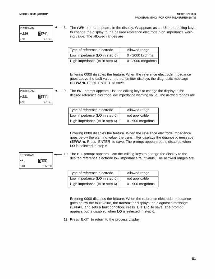
81
8. The rWH prompt appears. In the display, W appears as w j. Use the editing keysto change the display to the desired reference electrode high impedance warn-ing value. The allowed ranges are
Type of reference electrode Allowed rangeLow impedance (LO in step 6) 0 - 2000 kilohmsHigh impedance (HI in step 6) 0 - 2000 megohms
Entering 0000 disables the feature. When the reference electrode impedancegoes above the fault value, the transmitter displays the diagnostic messagerEFWArn. Press ENTER to save.
9. The rWL prompt appears. Use the editing keys to change the display to thedesired reference electrode low impedance warning value. The allowed ranges are
Type of reference electrode Allowed rangeLow impedance (LO in step 6) not applicableHigh impedance (HI in step 6) 0 - 900 megohms
Entering 0000 disables the feature. When the reference electrode impedancegoes below the warning value, the transmitter displays the diagnostic messagerEFWArn. Press ENTER to save. The prompt appears but is disabled whenLO is selected in step 6.
10. The rFL prompt appears. Use the editing keys to change the display to thedesired reference electrode low impedance fault value. The allowed ranges are
Type of reference electrode Allowed rangeLow impedance (LO in step 6) not applicableHigh impedance (HI in step 6) 0 - 900 megohms
Entering 0000 disables the feature. When the reference electrode impedancegoes below the fault value, the transmitter displays the diagnostic messagerEFFAIL and sets a fault condition. Press ENTER to save. The promptappears but is disabled when LO is selected in step 6.
11. Press EXIT to return to the process display.
MODEL 3081 pH/ORP SECTION 10.0PROGRAMMING FOR ORP MEASUREMENTS
PROGRAM
rWJLEXIT ENTER
0000
PROGRAM
rFLEXIT ENTER
0000
PROGRAM
rWJHEXIT ENTER
0040

82
MODEL 3081 pH/ORP SECTION 10.0PROGRAMMING FOR ORP MEASUREMENTS
10.5 TEMPERATURE ELEMENT10.5.1 PurposeThis section describes how to match the transmitter to the type of temperatureelement in the ORP sensor.
10.5.2 DefinitionTEMPERATURE ELEMENT: ORP sensors use a variety of temperature ele-ments. The Model 3081 ORP transmitter recognizes the following temperatureelements and configurations:
a. three and four wire 100 ohm platinum RTDs
b. three and four wire 1000 ohm platinum RTDs
c. 3000 ohm Balco RTD
A 100 ohm platinum RTD has a resistance of 100 ohms at 0°C. A 1000 ohm plat-inum RTD has a resistance of 1000 ohms at 0°C. A 3000 ohm Balco RTD (Balcois an alloy of 70% nickel and 30% iron) has a resistance of 3000 ohms at 25°C.Although only two lead wires are necessary to connect the RTD to the transmit-ter, connecting a third (and sometimes fourth) wire allows the transmitter to cor-rect for the resistance of the lead wires and for changes in wire resistance withtemperature.
The Model 3081 transmitter can also be used with a two-wire RTD. Select a three-wire configuration and jumper the RTD return and -RTD sense terminals (termi-nals 3 and 4, respectively).
10.5.2 Procedure
1. Press PROG on the infrared remote controller (IRC).
2. Press NEXT until the tEMP sub-menu appears in the display. PressENTER .
3. The screen shows the tC prompt. Press or to scroll to the desired tem-perature element and wiring configuration. Press ENTER to save.
1000-3 3 wire 1000 ohm RTD1000-4 4 wire 1000 ohm RTD100-3 3 wire 100 ohm RTD100-4 4 wire 100 ohm RTD3000 3000 ohm Balco RTD
NOTEA jumper on the analog board must also be set to the appropriate RTDtype. See Section 2.2, Pre-Installation Set Up.
4. Press EXIT to return to the process display.
PROGRAM
tCEXIT ENTER
1 00-33
PROGRAM
tEMPEXIT NEXT ENTER

83
MODEL 3081 pH/ORP SECTION 10.0PROGRAMMING FOR ORP MEASUREMENTS
PROGRAM
OUtPUtEXIT ENTER
CUR
PROGRAM
CODEEXIT ENTER
000
PROGRAM
tYPEEXIT ENTER
PH
PROGRAM
tEMPEXIT ENTER
C
PROGRAM
dISPLAYEXIT NEXT ENTER
10.6 DISPLAY UNITS
10.6.1 Purpose
This section describes how to do the following:
1. switch the process display units between pH and ORP (millivolts),
2. select °C or °F for the temperature display,
3. select percent of full scale or milliamps for the output display,
4. program a security code.
10.6.2 Definitions
1. DISPLAY UNITS. Select pH if the transmitter is being used to measure pH. SelectORP if the transmitter is being used to measure ORP. The units selected are shownin the main display next to the measured value.
2. OUTPUT CURRENT DISPLAY. The transmitter generates a 4 to 20 mA output signaldirectly proportional to the ORP of the sample. The output signal also appears on thetemperature-output display line. The output signal can be displayed as current (in mA)or as percent of full scale.
3. SECURITY CODE. The security code unlocks the transmitter and allows completeaccess to all menus. The transmitter is shipped with security code disabled.
10.6.3 Procedure
1. Press PROG on the infrared remote controller (IRC).
2. Press NEXT until the dISPLAY sub-menu appears. Press ENTER .
3. The screen displays the tYPE prompt. Press or to toggle between pH and OrP.Press ENTER to save.
4. The screen displays the tEMP prompt.Press or to toggle between C and F.Press ENTER to save.
5. The screen displays the OUtPUt prompt. Press or to toggle between % andCUr. Press ENTER to save.
6. The screen displays the COdE prompt. Use the editing keys to enter a security codebetween 001 and 999. Entering 000 disables the security feature. Press ENTER tosave.
7. Press EXIT to return to the process display.

84
MODEL 3081 pH/ORP SECTION 10.0PROGRAMMING FOR ORP MEASUREMENTS
PROGRAM
tEStEXIT ENTER
1 2 .00
PROGRAM
SIM OOUtPUtEXIT NEXT ENTER
10.7 GENERATING A TEST CURRENT
10.7.1 Purpose
This section describes how to generate output currents for testing recorders anddata handling systems.
10.7.2 What happens while the transmitter is generating a test current?
1. The output current goes to the programmed test value and remains there untilthe TEST function is disabled.
2. The main display continues to show the ORP of the process stream. The wordHOLD appears in the display.
3. The test current value supersedes both the HOLD value and the FAULTvalue.
4. If a fault occurs while the transmitter is generating the test current, the wordFAULT appears in the display and the display flashes.
10.7.3 Procedure
1. Press PROG on the infrared remote controller (IRC).
2. Press NEXT until the SIM OUtPUt sub-menu appears. Press ENTER .
3. The tESt prompt appears. Use the editing keys to change the number to thedesired value. The allowed values are between 3.80 mA and 22.00 mA.
4. Press ENTER to start the test current.
5. To end the test current, press EXIT .
6. Press EXIT to return to the process display.
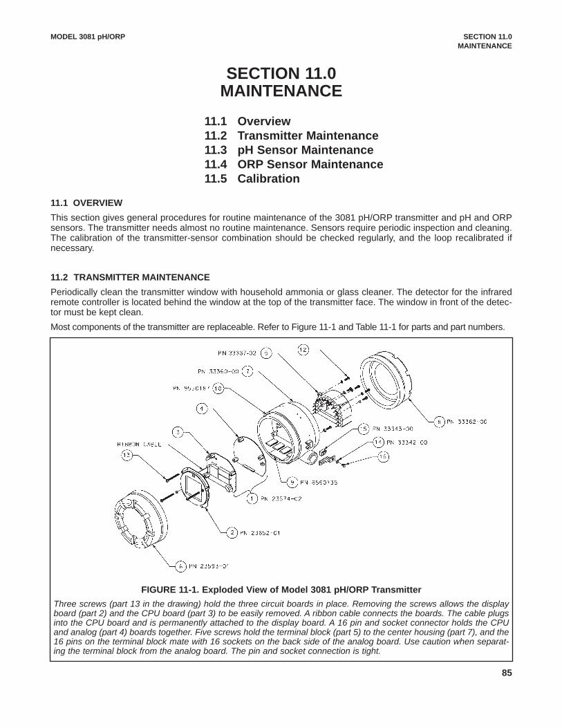
85
MODEL 3081 pH/ORP SECTION 11.0MAINTENANCE
SECTION 11.0MAINTENANCE
11.1 OVERVIEWThis section gives general procedures for routine maintenance of the 3081 pH/ORP transmitter and pH and ORPsensors. The transmitter needs almost no routine maintenance. Sensors require periodic inspection and cleaning.The calibration of the transmitter-sensor combination should be checked regularly, and the loop recalibrated ifnecessary.
11.2 TRANSMITTER MAINTENANCEPeriodically clean the transmitter window with household ammonia or glass cleaner. The detector for the infraredremote controller is located behind the window at the top of the transmitter face. The window in front of the detec-tor must be kept clean.Most components of the transmitter are replaceable. Refer to Figure 11-1 and Table 11-1 for parts and part numbers.
11.1 Overview11.2 Transmitter Maintenance11.3 pH Sensor Maintenance11.4 ORP Sensor Maintenance11.5 Calibration
FIGURE 11-1. Exploded View of Model 3081 pH/ORP TransmitterThree screws (part 13 in the drawing) hold the three circuit boards in place. Removing the screws allows the displayboard (part 2) and the CPU board (part 3) to be easily removed. A ribbon cable connects the boards. The cable plugsinto the CPU board and is permanently attached to the display board. A 16 pin and socket connector holds the CPUand analog (part 4) boards together. Five screws hold the terminal block (part 5) to the center housing (part 7), and the16 pins on the terminal block mate with 16 sockets on the back side of the analog board. Use caution when separat-ing the terminal block from the analog board. The pin and socket connection is tight.
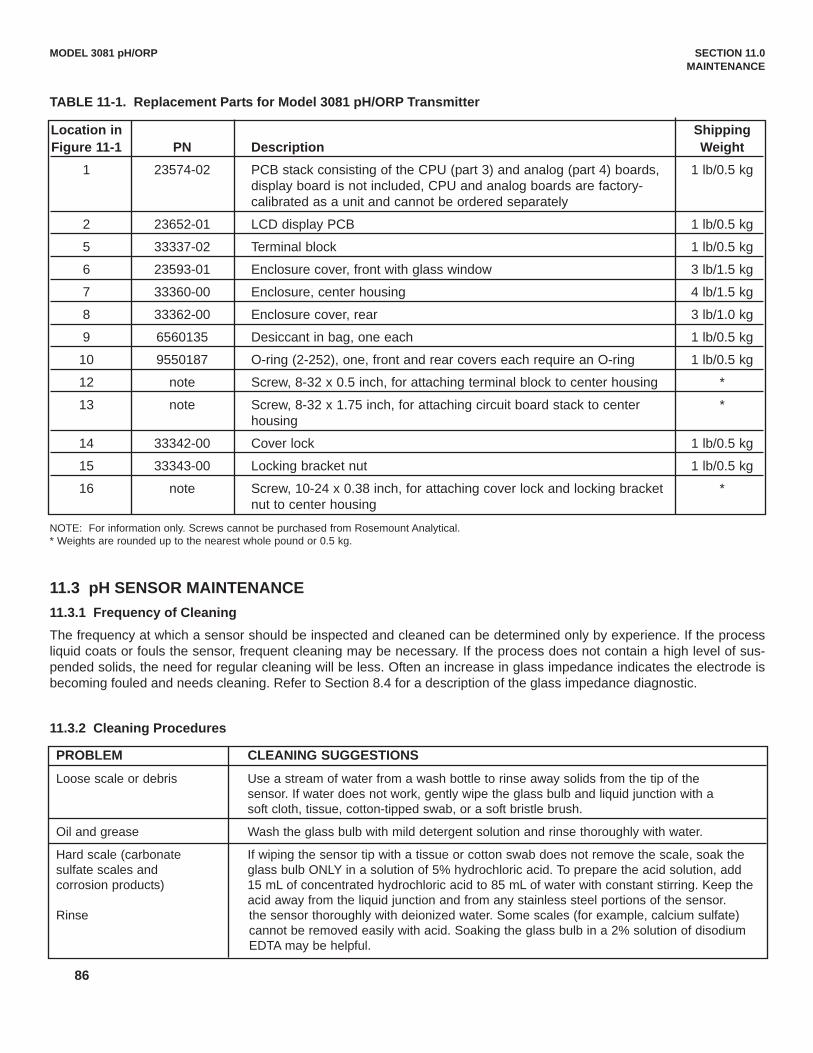
86
MODEL 3081 pH/ORP SECTION 11.0MAINTENANCE
TABLE 11-1. Replacement Parts for Model 3081 pH/ORP Transmitter
PROBLEM CLEANING SUGGESTIONS
Loose scale or debris Use a stream of water from a wash bottle to rinse away solids from the tip of the sensor. If water does not work, gently wipe the glass bulb and liquid junction with a soft cloth, tissue, cotton-tipped swab, or a soft bristle brush.
Oil and grease Wash the glass bulb with mild detergent solution and rinse thoroughly with water.
Hard scale (carbonate If wiping the sensor tip with a tissue or cotton swab does not remove the scale, soak thesulfate scales and glass bulb ONLY in a solution of 5% hydrochloric acid. To prepare the acid solution, add corrosion products) 15 mL of concentrated hydrochloric acid to 85 mL of water with constant stirring. Keep the
acid away from the liquid junction and from any stainless steel portions of the sensor.Rinse the sensor thoroughly with deionized water. Some scales (for example, calcium sulfate)
cannot be removed easily with acid. Soaking the glass bulb in a 2% solution of disodium EDTA may be helpful.
Location in ShippingFigure 11-1 PN Description Weight
1 23574-02 PCB stack consisting of the CPU (part 3) and analog (part 4) boards, 1 lb/0.5 kgdisplay board is not included, CPU and analog boards are factory-calibrated as a unit and cannot be ordered separately
2 23652-01 LCD display PCB 1 lb/0.5 kg
5 33337-02 Terminal block 1 lb/0.5 kg
6 23593-01 Enclosure cover, front with glass window 3 lb/1.5 kg
7 33360-00 Enclosure, center housing 4 lb/1.5 kg
8 33362-00 Enclosure cover, rear 3 lb/1.0 kg
9 6560135 Desiccant in bag, one each 1 lb/0.5 kg
10 9550187 O-ring (2-252), one, front and rear covers each require an O-ring 1 lb/0.5 kg
12 note Screw, 8-32 x 0.5 inch, for attaching terminal block to center housing *
13 note Screw, 8-32 x 1.75 inch, for attaching circuit board stack to center *housing
14 33342-00 Cover lock 1 lb/0.5 kg
15 33343-00 Locking bracket nut 1 lb/0.5 kg
16 note Screw, 10-24 x 0.38 inch, for attaching cover lock and locking bracket *nut to center housing
NOTE: For information only. Screws cannot be purchased from Rosemount Analytical.* Weights are rounded up to the nearest whole pound or 0.5 kg.
11.3 pH SENSOR MAINTENANCE11.3.1 Frequency of CleaningThe frequency at which a sensor should be inspected and cleaned can be determined only by experience. If the processliquid coats or fouls the sensor, frequent cleaning may be necessary. If the process does not contain a high level of sus-pended solids, the need for regular cleaning will be less. Often an increase in glass impedance indicates the electrode isbecoming fouled and needs cleaning. Refer to Section 8.4 for a description of the glass impedance diagnostic.
11.3.2 Cleaning Procedures

87
When using acid or alkaline solvents, be careful to keep the solvent away from the liquid junction. If the cleaning sol-vent contacts the junction, hydrogen ions (acid solvent) or hydroxide ions (alkaline solvent) will diffuse into the junc-tion. Because hydrogen and hydroxide ions have much greater mobility than other ions, they produce a large junctionpotential. When the electrode goes back in service, the hydrogen or hydroxide ions slowly diffuse out of the junction,causing the liquid junction potential and the pH reading to drift. It may take hours or days for the reading to stabilize.For a discussion of the influence of ion mobility on liquid junction potentials, see Section 13.4.Consult the sensor instruction manual for additional information. Always recalibrate the sensor after cleaning. If the sensor was cleaned with detergent or acid, soak the sensor in pH4 or pH 7 buffer for at least an hour before calibrating.
11.3.3 Checking the Reference Electrode.Some processes contain substances, for example, sulfides, that poison the reference electrode. Poisoning alters theelectrode potential. For example, sulfide poisoning converts the reference electrode from a silver/silver chloride elec-trode into a silver/silver sulfide electrode, causing a shift in potential of several hundred millivolts.A good way to check for poisoning is to compare the voltage of the reference electrode with a silver/silver chlorideelectrode that is known to be good. The reference electrode from a new sensor is the best choice. To check the sus-pect electrode, place both sensors in a beaker containing buffer or a solution of potassium chloride. Connect the ref-erence leads to a voltmeter and measure the potential difference. If the suspect electrode is good, the differenceshould be no more than about 20 mV. Refer to Figure 11-2. A poisoned reference electrode usually requires replace-ment.
A laboratory silver/silver chloride reference electrode can be used in place of the second sensor. All RosemountAnalytical pH sensors have a silver/silver chloride reference, and most sensors use gelled saturated potassium chlo-ride for the fill. The potentials of a good sensor reference electrode and a saturated silver/silver chloride laboratoryelectrode will agree within about 20 mV.
11.3.4 Rejuvenating Reference ElectrodesOccasionally, a poisoned or plugged reference electrode can be reconditioned. Although the electrode seldomrecovers completely, the procedure might extend the life of the sensor by a few weeks.
a. Clean the sensor as thoroughly as possible.b. Soak the sensor for several hours in a hot (NOT BOILING) 3% potassium chloride solution. Prepare the
solution by dissolving 3 g of potassium chloride in 100 mL of water.c. Soak the sensor in pH 4 buffer at room temperature overnight.d. Calibrate the sensor in buffers and retest it in the process liquid.
MODEL 3081 pH/ORP SECTION 11.0MAINTENANCE
FIGURE 11-2. Checking the Potential of the Reference Electrode.Refer to the wiring diagram(s) for the sensors to identify the reference leads.
88
11.4 ORP SENSOR MAINTENANCE11.4.1 Frequency of CleaningThe frequency at which an ORP sensor should be inspected and cleaned can be determined only by experience. If theprocess liquid coats or fouls the sensor, frequent cleaning may be necessary. If the process does not contain a high levelof suspended solids, the need for regular cleaning will be less.
11.4.2 Cleaning ProceduresThe platinum electrode is easily cleaned by using a tissue to rub the metal surface with a paste of baking soda (sodiumbicarbonate). A clean platinum electrode is bright and shiny.
11.4.3 Checking the Reference ElectrodeORP electrodes manufactured by Rosemount Analytical have a silver/silver chloride reference. Section 11.3.3 describeshow to check the performance of the reference electrode.
11.5 CALIBRATION11.5.1 GeneralMany users regard calibration as a routine part of sensor/transmitter maintenance. Procedures for calibrating pH sensors,ORP sensors, and general information regarding the use of pH calibration buffers and ORP standards are given inSections 7.0 Calibration of pH Measurements, 9.0 Calibration of ORP Measurements, 13.0 pH Measurements, and 14.0ORP Measurements.
11.5.2 Calibration FrequencyThe frequency at which sensors should be calibrated can be determined only by experience. Many factors influence cali-bration frequency. Sensors installed in dirty or corrosive process streams usually require more frequent calibration thansensors used in clean water. Sensors measuring extreme pH values, particularly high pH, also require more frequent cali-bration than sensors measuring mid-range pH. The width of the pH or ORP control range and the consequences of anout-of-limits condition has a major influence on calibration frequency. The narrower the control range and the greater thesensitivity of the process to control excursions, the more often the sensor should be checked. Finally, if monitoring dataare reported to regulatory agencies, the agency itself may dictate the calibration frequency.
Use the following procedure to determine how often a pH sensor should be calibrated.1. Calibrate the sensor. Record the date of calibration and the sensor response in buffers. That is, after calibrating,
place the sensor back in the buffers and record the pH and temperature reading in each buffer. Also note the value ofthe reference offset and slope.
2. Install the sensor in the process stream.3. After the appropriate period—two weeks for a clean process, several days for a dirty or aggressive process—remove
the sensor and check its performance in buffers. Record the pH and temperature readings. The performance of thesensor in buffer after it has been in service is called the as-found condition. Keeping a good record of as-found data isan important step in determining the calibration frequency.
4. If the as-found data are acceptable, do not recalibrate the sensor. Return it to the process. Continue checking the cal-ibration at the same interval.
5. If the as-found data are not acceptable, recalibrate the sensor. After calibration, check the sensor response in eachbuffer and record the results. Also note the reference offset and the slope. Return the sensor to service. Check thesensor again after a period shorter than the one originally selected. For example, if the first interval was two weeks,repeat the check after one week.
6. After a while it will become apparent how long the sensor holds calibration. The minimum calibration frequency canthen be determined.
7. Check the calibration of the sensor at least several times during the regular calibration interval. Interim checks verifythe sensor is still in calibration and validate the process measurements made since the last calibration or calibrationcheck.
MODEL 3081 pH/ORP SECTION 11.0MAINTENANCE

89
MODEL 3081 pH/ORP SECTION 12.0TROUBLESHOOTING
SECTION 12.0TROUBLESHOOTING
12.1 WARNING AND FAULT MESSAGES12.2 CALIBRATION ERRORS 12.3 TROUBLESHOOTING - GENERAL12.4 TROUBLESHOOTING WHEN A DIAGNOSTIC MESSAGE IS SHOWING12.5 TROUBLESHOOTING WHEN NO DIAGNOSTIC MESSAGE IS SHOWING12.6 SYSTEMATIC TROUBLESHOOTING12.7 DISPLAYING DIAGNOSTIC VARIABLES12.8 TESTING THE TRANSMITTER BY SIMULATING pH12.9 FACTORY ASSISTANCE AND REPAIRS
12.1 WARNING AND FAULT MESSAGESThe Model 3081 pH/ORP transmitter continuously monitors the measurementloop (sensor and transmitter) for conditions that cause erroneous measurements.When a problem occurs, the transmitter displays either a warning or fault mes-sage. A warning alerts the user that a potentially system disabling condition exists.If the condition causing the problem is not corrected, there is a high probabilitythat the system will soon fail. A fault alerts the user that a system disabling con-dition exists. If a fault message is showing, all measurements should be regard-ed as erroneous.
When a WARNING condition exists:1. The main display remains stable; it does not flash.2. A warning message appears alternately with the temperature/output display.
See Figure 12-1. See Section 12.4 for an explanation of the different warn-ings and suggested ways of correcting the problem.
When a FAULT exists:1. The main display flashes.2. The words FAULT and HOLD appear in the main display.3. A fault message appears alternately with the temperature/output display. See
Figure 12-2. See Section 12.4 for an explanation of the different fault mes-sages and suggested ways of correcting the problem.
4. The output current will remain at the present value or go to the programmedfault value. See Section 8.3 Output Ranging for pH Measurements, or Section10.3 Output Ranging for ORP Measurements for details on how to programthe current generated during a fault condition.
5. If the transmitter is in HOLD when the fault occurs, the output remains at theprogrammed hold value. To alert the user that a fault exists, the word FAULTappears in the main display, and the display flashes. A fault or diagnosticmessage also appears.
6. If the transmitter is simulating an output current when the fault occurs, thetransmitter continues to generate the simulated current. To alert the user thata fault exists, the word FAULT appears in the display, and the display flash-es.
FIGURE 12-1. WarningAnnunciation
When a non-disabling problemoccurs, a warning message appearsalternately with the temperature/ out-put display.
FIGURE 12-2. Fault AnnunciationWhen a disabling condition, a fault,occurs, the display appears as pic-tured above. To further alert the userthat measurements are in error, thedisplay flashes. Diagnostic mes-sages appear in the temper-ature/output area on the screen.

90
12.2 CALIBRATION ERRORS If an error occurs during calibration, an error message appears in the main display, and the transmitter does not updatethe calibration. The calibration errors are Std Err, SLOPE Err LO, and SLOPE Err HI. See Section 12.4 for an explana-tion of the error messages and suggested ways of correcting the problem.
12.3 TROUBLESHOOTING - GENERALTroubleshooting is easy as 1, 2, 3 . . .Step 1 Look for a diagnostic message on the display to help identify the problem. Refer to Section 12.4 for an explana-
tion of the message and a list of the possible problems that triggered it.
Step 2 Refer to Section 12.5 for common measurement problems and the recommended actions to resolve them.
Step 3 Follow the step by step troubleshooting approach, offered in Section 12.6, to diagnose and correct less commonor more complex problems.
12.4 TROUBLESHOOTING WHEN A DIAGNOSTIC MESSAGE IS SHOWINGThe Model 3081 pH/ORP transmitter continuously monitors the measurement loop (sensor and transmitter) for problems.If a problem is detected, the transmitter displays a fault or error message. The message appears in the temperature/out-put area of the main display. The table lists each diagnostic message and the section to consult for help.
MESSAGE SECTIONGLASSFAIL 12.4.1
GLASSWArn 12.4.2
rEF FAIL 12.4.3
rEF WArn 12.4.4
CALIbrAtE 12.4.5
tEMP HI 12.4.6
tEMP LO 12.4.6
LInE FAIL 12.4.7
InPUt WArn 12.4.8
SLOPE Err LO 12.4.9
SLOPE Err HI 12.4.10
Std Err 12.4.11
rOM FAIL 12.4.12
CPU FAIL 12.4.12
AdC WArn 12.4.13
CyCLE PWr 12.4.13
WrItE Err 12.4.14
FACt FAIL 12.4.15
MODEL 3081 pH/ORP SECTION 12.0TROUBLESHOOTING

91
MODEL 3081 pH/ORP SECTION 12.0TROUBLESHOOTING
12.4.1 GLASSFAILGLASSFAIL is an electrode fault message. It means the glass impedance is outside the programmed Glass Fault High(GFH) or Glass Fault Low (GFL) limit. Glass Fault High suggests the electrode is aging or the electrode is not immersedin the process liquid. Glass Fault Low implies the pH sensitive glass is cracked. GLASSFAIL also appears if inappropri-ate limits have been entered into the transmitter.
If the measurement system was previously commissioned and operating correctly, GLASSFAIL likely means a real prob-lem exists. However if the system is being started up or if the advanced diagnostic feature is being used for the first time,GLASSFAIL could be caused by a miswired sensor or by programmed limits that are not correct for the sensor.
NOTEGLASSFAIL is a sensor diagnostic message. Sensor diagnostic mes-sages are optional. They can be turned off. To disable sensor diagnosticmessages, refer to Section 8.4.3.
Troubleshooting Flowchart - GLASSFAILA. Be sure the sensor is completely immersed in the process liquid.
If the diagnostic message disappears, the sensor is in good condition.
If the diagnostic message remains, go to step B.
B. Measure the glass impedance. See Section 12.7 for the procedure. Note the reading.
If the glass impedance is low (<40 megohms)...
1. Be sure the position of switch S-1 on the analog board matches the location of the preamplifier. See Section 2.2.
If switch S-1 was correct go to step 2.
If moving the switch to the correct position makes the diagnostic message disappear, the sensor is in good condition.
If after moving the switch, the glass impedance is still low, go to step 2.
2. Calibrate the sensor. Use the autocalibration procedure in Section 7.5.
If the sensor calibrates properly...
a. The sensor is in good condition, but the Glass Fail Low (GFL) limit is set too high.
b. Lower the GFL limit to about 10 megohms below the glass impedance value (GIMP) measured in step B.
c. If the Glass Warning Low (GWL) message was also flashing, lower the limit from its former value by the same amount GFL was lowered from its former value.
If the sensor cannot be calibrated...
The pH sensitive glass membrane is likely cracked and the sensor must be replaced. The crack in the glass may not be visible or may be difficult to see.
If the glass impedance is high (>800 megohms)...
1. Check that the sensor is correctly wired to the transmitter. See the appropriate wiring diagram in Section 3.0. Pay particular attention to the following:
a. For Rosemount Analytical PLUS (+) and TUpH sensors with integral preamplifiers, the blue solution ground wire must be attached to TB-8 (SOL GND) and the gray reference in wire must be attached to TB-7 (REF IN). (NOTE: TB-8 means terminal 8 on the terminal board.)

92
MODEL 3081 pH/ORP SECTION 12.0TROUBLESHOOTING
b. If the sensor was wired with the blue solution ground wire unattached and a jumper between terminals TB-8 and TB-7, remove the jumper and reattach the blue solution ground wire to TB-8. Keep the gray reference in wire attached to TB-7.
c. For Rosemount Analytical PLUS (+) and TUpH sensors that do not have an integral preamplifier, attach the blue solution ground wire to TB-8 or, better, leave the blue wire unattached and jumper TB-7 to TB-8.
d. If the sensor does not have a blue solution ground wire, jumper terminals TB-7 and TB-8.
If the wiring was correct and the glass impedance is still high, go on to step 2.
If correcting wiring errors causes the diagnostic message to disappear, the sensor is in good condition.
If after correcting wiring errors, the glass impedance is still high go on to step 2.
2. Inspect and clean the sensor. Refer to Section 11.3. After cleaning the sensor, calibrate it following the auto calibration procedure in Section 7.5. Be sure to note the sensor slope.
If cleaning the sensor lowers the impedance below 800 megohms...
a. The sensor is in good condition.
b. Return the calibrated sensor to service.
If cleaning does not lower the glass impedance and the sensor can be calibrated...
a. The sensor is probably in good condition; however, it may be nearing the end of its life. The electrodeslope is a good indicator of remaining life.
SLOPE CONDITION OF SENSOR54-60 mV/unit pH Sensor is in good condition.
48-50 mV/unit pH Sensor is nearing the end of its life. Once the slope drops below 48 mV/unit pH, the sensor can no longer be calibrated.
b. The Glass Fail High (GFH) limit is probably set too low for the sensor. Set the GFH limit to about 150 megohms greater than the measured glass impedance.
c. If the GLASSWArn message was also flashing, raise the GWH limit from its former value by the same amount GFH was raised from its former value.
If cleaning does not lower the glass impedance and the sensor cannot be calibrated...
The sensor has failed and should be replaced.
If the glass impedance is moderate (between 40 and 800 megohms)...
1. The sensor may be dirty, in which case cleaning it will lower the impedance reading. The sensor may also be in good condition. The warning and fail limits are simply set too low.
2. Inspect and clean the sensor. Refer to Section 11.3. After cleaning the sensor, calibrate it following the auto calibration procedure in Section 7.5. Be sure to note the sensor slope.
If cleaning the sensor reduces the impedance...
a. The sensor is in good condition.
b. Return the calibrated sensor to service.
If cleaning does not lower the glass impedance and the sensor can be calibrated...
a. The sensor is probably in good condition; however it may be nearing the end of its life. The electrode slope is a good indicator of remaining life.

93
MODEL 3081 pH/ORP SECTION 12.0TROUBLESHOOTING
SLOPE STATUS OF SENSOR54-60 mV/unit pH Sensor is in good condition.
48-50 mV/unit pH Sensor is nearing the end of its life. Once the slope drops below 48 mV/unit pH, the sensor can no longer be calibrated.
b. The Glass Fail High (GFH) limit is probably set too low for the sensor. Set the GFH limit to about 150 megohms greater than the measured glass impedance.
c. If the GLASSWArn message was also flashing, raise the GWH limit from its former value by the same amount GFH was raised from its former value.
If cleaning does not lower the glass impedance and the sensor cannot be calibrated...
The sensor has failed and should be replaced.
12.4.2 GLASSWArnGLASSWArn is an electrode fault message. It means the glass impedance is outside the programmed Glass WarningHigh (GWH) or Glass Warning Low (GWL) limit. Ideally, when the measurement system exceeds the glass warning limits,the user will have adequate time to diagnose and correct problems before a failure occurs. High impedance implies theelectrode is aging or the sensor is not completely submerged in the process liquid. Low impedance suggests the pH sen-sitive glass is cracked. The message also appears if inappropriate limits have been entered into the transmitter.
If the measurement system was previously commissioned and operating correctly, GLASSWArn likely means a real prob-lem exists. However, if the system is being started up or if the advanced diagnostic feature is being used for the first time,GLASSWArn could be caused by a miswired sensor or by programmed limits that are not correct for the sensor.
NOTEGLASSWArn is a sensor diagnostic message. All sensor diagnosticmessages are optional. They can be turned off. To disable sensor diag-nostic messages, refer to Section 8.4.3.
Troubleshooting Flowchart - GLASSWArnTroubleshooting GLASSWArn problems is exactly the same steps as troubleshooting GLASSFAIL problems. Refer toSection 12.4.1.
12.4.3 rEF FAILrEF FAIL is an electrode fault message. rEF FAIL means that the reference impedance exceeds the programmedReference Fault High (RFH) limit. A plugged or dry reference junction is the usual cause of a high reference impedance.High reference impedance also occurs if the sensor is not submerged in the process liquid or if inappropriate limits havebeen entered into the transmitter.
If the measurement system was previously commissioned and operating correctly, rEF FAIL likely means a real problemexists. However, if the system is being started up or if the advanced diagnostic feature is being used for the first time,rEFFAIL could be caused by a miswired sensor or by programmed limits that are not correct for the sensor.
NOTErEF FAIL is a sensor diagnostic message. All sensor diagnostic mes-sages are optional. They can be turned off. To disable sensor diagnosticmessages, refer to Section 8.4.3.

94
MODEL 3081 pH/ORP SECTION 12.0TROUBLESHOOTING
Troubleshooting Flowchart - rEF FAILA. Be sure the sensor is completely immersed in the process liquid.
If the diagnostic message disappears, the sensor is in good condition.
If the diagnostic message remains, go to step B.
B. Check that the sensor is properly wired to the transmitter. See the appropriate wiring diagram in Section 3.0. Be sure the reference in wire is attached to TB-7 and the solution ground wire is attached to TB-8. (NOTE: TB-8 means
terminal 8 on the terminal board.)
If correcting wiring problems makes the diagnostic message disappear, the sensor is in good condition.
If wiring is correct and the message still remains, go to step C.
C. Measure and make a note of the reference impedance (rIMP). See Section 12.7.
If the reference impedance is low (<70 kilohms)...
a. The reference electrode is in good condition. pH sensors manufactured by Rosemount Analytical use low impedance silver/silver chloride reference electrodes.
b. The reference failure high (RFH) limit is probably set too low. Change the limit to a value about 50 kilohms greater than the measured reference impedance. If rEF WARN was also displayed, change the reference warning high (RWH) limit to about 25 kilohms above the measured reference impedance.
If the reference impedance is high (>70 kilohms)...
1. The sensor may be dirty, in which case cleaning it will lower the impedance. If the sensor is rebuildable, the reference electrolyte may be depleted. Finally, the sensor may be in good condition. The warning andfailure limits are simply set too high.
2. Inspect and clean the sensor. Refer to Section 11.3. If the sensor is rebuildable, replace the reference junction and replenish the electrolyte solution. Refer to the sensor instruction manual for details. Check the reference impedance again.
If cleaning the sensor reduces the impedance...
a. The sensor is in good condition. Calibrate the sensor and return it to the process.
b. Change the reference failure high (RFH) limit to a value about 50 kilohms greater than the measured reference impedance. If rEF WARN was also displayed, change the reference warning high (RWH) limit to about 25 kilohms above the measured reference impedance.
If cleaning does not reduce the impedance and the sensor is not rebuildable...
a. Try the reference junction rejuvenation procedure described in Section 11.3.
b. The rejuvenation procedure may not work. At best it will get a little more life out of a sensor with a plugged reference.
c. Whether or not the rejuvenation procedure worked, go on to step 3.
3. Recalibrate the sensor using the auto calibration procedure in Section 7.5.
If the sensor can be calibrated...
a. The sensor is in good condition. Return it to the process.
b. Change the reference failure high (RFH) limit to a value about 50 kilohms greater than the measured reference impedance. If rEF WARN was also displayed, change the reference warning high (RWH) limit to about 25 kilohms greater than the measured reference impedance.
If the sensor cannot be calibrated...
The sensor has failed and must be replaced.

95
MODEL 3081 pH/ORP SECTION 12.0TROUBLESHOOTING
12.4.4 rEFWArnrEF WArn is an electrode fault message. It means the reference electrode impedance exceeds the programmedReference Warning High (RWH) limit. Ideally, when the measurement system exceeds the warning limits, the user willhave adequate time to diagnose and correct problems before a failure occurs. A high reference impedance implies thatthe liquid junction is plugged or the reference electrolyte is depleted. The message also appears if an inappropriate limithas been entered into the transmitter.
If the measurement system was previously commissioned and operating correctly, rEF WArn likely means a real problemexists. However, if the system is being started up or if the advanced diagnostic feature is being used for the first time, rEFWArn could be caused by a miswired sensor or by programmed limits that are not correct for the sensor.
NOTErEF WArn is a sensor diagnostic message. Sensor diagnostic messagesare optional. They can be turned off. To disable sensor diagnostic mes-sages, refer to Section 8.4.3.
Troubleshooting Flowchart - rEF WArnTroubleshooting rEF WArn problems is exactly the same as troubleshooting rEF FAIL problems. Refer to Section 12.4.3.
12.4.5 CALIbrAtECALIbrAtE is a diagnostic intended for future use. If the CALIbrAtE message is showing go to Section 8.4 and disableCALIbrAte.
12.4.6 tEMP HI and tEMP LOtEMP HI and tEMP LO mean the transmitter has detected a problem with the temperature measuring circuit. The problemmay lie in the sensor, the cable, or the transmitter. The determination of temperature is an integral part of the pH meas-urement. Therefore, failure of the temperature measuring circuit is a system disabling condition. However, in an emer-gency, automatic temperature compensation can be disabled and the transmitter placed in manual temperaturecompensation. Refer to Section 8.5. For manual temperature compensation, choose a temperature equal to the averagetemperature of the process. The resulting pH reading will be in error. The more variable the temperature and the furtherthe pH from 7, the greater the error.
Troubleshooting Flowchart- tEMP HI and tEMP LOA. Check wiring, jumper settings, and software settings.
1. Check the wiring between the sensor and the transmitter. Refer to the appropriate wiring diagram in Section 3.0. Pay particular attention to TB-3 (RTD RTN), TB-4 (RTD SN), and TB-5 (RTD RTN). (NOTE: TB-3 means terminal 3 on the terminal board.)
2. Be sure the position of the RTD jumper on the analog board matches the type of RTD in the sensor. See Section 2.2.
3. Be sure the software settings in Section 8.5 match the type of RTD in the sensor.
If the diagnostic message disappears, the sensor is in good condition.
If the message persists, go to step B.

96
MODEL 3081 pH/ORP SECTION 12.0TROUBLESHOOTING
B. Check the sensor.
Refer to the wiring diagrams in Section 3.0 to identify the RTD leads. Disconnect the RTD leads and measure theresistances shown in Figure 12-3. The measured resistance should agree with the value in Table 12-1 to within about 1%. If the measured resistance is appreciably different (between 1 and 5%) from the value shown, the discrepancy can be calibrated out. See Section 8.5.
If a connection is open or shorted and it should not be, the sensor has failed. Replace the sensor.
If the RTD is different from what was expected, for example, the sensor contains a Pt 100, not a Pt 1000 RTD, reset the jumper and reconfigure the software to match the actual RTD
If the measured resistances are acceptable, go to step C.
FIGURE 12-3. Three-wire RTD Consult the table for resistance-temperature data. Lead resistance is about0.05 ohm/ft at 25°C. Therefore, 15 feet of cable increases the resistance byabout 1.5 ohm. The resistance between the RTD return and RTD sense leadsshould be less than 2 ohms.
Temperature Pt 100 Pt 1000 3K BalcoResistance Resistance Resistance
0°C 100.0 ohms 1000 ohms 2670 ohms10°C 103.9 ohms 1039 ohms 2802 ohms20°C 107.8 ohms 1078 ohms 2934 ohms25°C 109.6 ohms 1096 ohms 3000 ohms30°C 111.7 ohms 1117 ohms 3067 ohms40°C 115.5 ohms 1155 ohms 3198 ohms50°C 119.4 ohms 1194 ohms 3330 ohms60°C 123.2 ohms 1232 ohms 3472 ohms70°C 127.1 ohms 1271 ohms 3594 ohms80°C 130.9 ohms 1309 ohms 3726 ohms90°C 134.7 ohms 1347 ohms 3858 ohms
100°C 138.5 ohms 1385 ohms 3990 ohms
TABLE 12-1. RTD Resistance Values

97
MODEL 3081 pH/ORP SECTION 12.0TROUBLESHOOTING
C. Check the transmitter.
1. Disconnect the RTD sensor leads and wire the circuit shown in Figure 12-4. Set the resistance to the value for 25°C shown in Table 12-1. The measured temperature should equal 25°C to within ±1°C.
If the measured temperature is correct, the transmitter is working properly.
If the measured temperature is incorrect, calibrate the transmitter against the standard resistance equivalent to 25°C. See Section 7.4 for the procedure. Change the resistance and verify that the temperature reading changes to the correct value.
If the transmitter works properly after temperature calibration, the original calibration was in error. Re-attach the RTD wires and check the temperature performance of the sensor.
If the reading is still wrong, the transmitter electronics have failed. Replace the electronic board stack (PN 23574-02).
12.4.7 LInE FAILLInE FAIL almost always means that the transmitter is measuring an incorrect resistance between terminal TB-3 (RTDRTN) and TB-4 (RTD SNS). These terminals are critical connections for the three-wire RTD measurement. Figure 12-3shows a three-wire RTD connection.
Troubleshooting Flowchart- LInE FAILA. Check for miswires and open connections at TB-3 and TB-4. Open connections can be caused by loose connections, poor spade crimps, or broken wires. Be sure to check junction boxes for proper pass through of all wires. See Section 3.0 for junction box wiring.
If correcting a wiring problem makes the message disappear, the system is in good condition.
If the message is still showing go to step B.
FIGURE 12-4. Temperature simulation into the Model 3081 pH/ORP transmitter.

98
MODEL 3081 pH/ORP SECTION 12.0TROUBLESHOOTING
B. The RTD sense or the RTD return wire inside the sensor cable may be broken. Keep the sensor wires attached and jumper TB-3 and TB-4.
If the diagnostic message disappears, either the RTD return or RTD sense wire is broken. To verify a broken wire,disconnect the leads and measure the resistance between them. Installing the jumper completes the circuit, but bypasses the three-wire function. The transmitter no longer corrects for changes in lead wire resistance withtemperature. Replace the sensor as soon as possible.
If the diagnostic message remains, go to step C.
C. The cable connecting the sensor to the transmitter may be too long. Test using a sensor with a shorter cable.
If shortening the cable eliminates the problem, move the transmitter closer to the sensor. It may also be possible to increase diameter of the RTD wires. Consult the factory for assistance.
If the diagnostic message remains go to step D.
D. Check the performance of the transmitter. Simulate both temperature and pH. See Section 12.4.6 (steps B and C) for temperature simulation and Section 12.8 for pH simulation.
If the transmitter fails either simulation, the electronic board stack (PN 23574-02) should be replaced.
If the transmitter passes the simulations, the transmitter is in good condition and the sensor should be replaced.
12.4.8 InPUt WArnInPUt WArn means that the input value or the calculated pH is outside the measurement range. The measured pH is lessthan -2 or greater than 16.
Troubleshooting Flowchart-InPUt WArnA. Check for miswires and open connections, particularly at TB-10. Open connections can be caused by loose
connections, poor spade crimps, or broken wires. Be sure to check junction boxes for proper pass through of all wires. See Section 3.0 for junction box wiring.
If correcting a wiring problem clears the message, the system is in good condition.
If the message is still showing go to step B.
B. Check that the transmitter is working properly by simulating a pH input. See Section 12.8.
If the transmitter does not respond to simulated inputs, replace the board stack (PN 23574-02).
If the transmitter performs satisfactorily and the preamplifier is located in a remote junction box or in a sensor -mounted junction box, go to step C.
If the transmitter performs properly and the preamplifier is located in the transmitter, the sensor has failed and should be replaced.
C. The problem may lie with the remote preamplifier or with the cable connecting the preamplifier and junction box to thetransmitter.
1. Be sure all wires between the junction box and the transmitter are connected.
2. Use Rosemount Analytical cable. Generic cable may not work. Refer to Section 3.0 for part numbers.
If the diagnostic message clears, the interconnecting cable was the problem.
If the message remains, go to step D.
D. Confirm that the problem is with the remote preamplifier. Wire the pH sensor directly to the transmitter. Move switch S-1 to the "transmitter" position for the test and return it to the "sensor or j-box" position afterwards. See Section 2.2.
If the error message clears, the remote preamplifier is faulty. Replace the preamplifier.
If the error message remains, the sensor has failed. Replace the sensor.

99
MODEL 3081 pH/ORP SECTION 12.0TROUBLESHOOTING
12.4.9 SLOPE Err LOSLOPE Err LO means that a two-point buffer calibration attempt has failed. The slope is too low (<40 mV/pH) for a goodmeasurement.
Troubleshooting Flowchart-SLOPE Err LOA. Repeat the calibration.
1. Inaccurate buffers can cause a low slope. Repeat the calibration using fresh buffers. Alkaline buffers, pH 10 or greater, are particularly susceptible to changing value in air or with age. If a high pH buffer was used in the failed calibration, try a lower pH buffer when repeating the calibration. For example, use pH 4 and 7 buffer instead of pH7 and 10 buffer.
2. Allow adequate time for readings in buffer to become constant. If the sensor was in a process substantially colderor hotter than the buffer, allow at least 20 minutes for readings in the buffer to stabilize. Alternatively, place the sensor in a container of water at ambient temperature for 20 minutes before starting the calibration.
3. Be sure the correct buffer values are being entered during calibration.
If the second calibration was successful, an error was made during the first attempt.
If the second calibration fails, go to step B.
B. Refer to the wiring diagrams in Section 3.0 and check wiring. Connections to TB-10, TB-7, and TB-8 are particularly important. Recalibrate the sensor using the auto calibration procedure in Section 7.5.
If wiring was the only problem, the sensor should calibrate.
If the message persists, go to step C.
C. Inspect and clean the sensor. See Section 11.3. Recalibrate the sensor using the auto calibration procedure in Section 7.5.
If the sensor was dirty, it should calibrate after cleaning.
If the message persists, go to step D.
D. Check for a faulty sensor.
If a spare sensor is available, connect it to the transmitter. Use the auto calibration procedure in Section 7.5 to calibrate the sensor.
If the new sensor cannot be calibrated, the transmitter is faulty. Go to step E.
If the new sensor can be calibrated, the old sensor has failed.
If a spare sensor is not available measure the glass impedance (GIMP). See Section 12.7.
If the glass impedance is less than about 20 megohms, the glass has cracked and the electrode must be replaced.
If the glass impedance is greater than about 20 megohms, the sensor is probably in good condition. Go to step E.
E. Check transmitter performance by simulating pH inputs. See Section 12.8.
If the transmitter performs satisfactorily, go to step F.
If the transmitter does not respond to simulated inputs, replace the board stack (PN 23574-02).
F. If the transmitter responds to simulated inputs, the problem must lie with the sensor or the interconnecting wiring. Verify the interconnecting wiring point to point. Fix or replace bad cable. If cable is good, replace the pH sensor.

100
MODEL 3081 pH/ORP SECTION 12.0TROUBLESHOOTING
12.4.10 SLOPE Err HISLOPE Err HI means that a two-point buffer calibration attempt has failed. The slope is too high (>62 mV/pH) for a goodmeasurement.
Troubleshooting Flowchart-SLOPE Err HIA. Repeat the calibration.
1. Inaccurate buffers can cause a low slope. Repeat the calibration using fresh buffers. Alkaline buffers, pH 10 or greater, are particularly susceptible to changing value in air or with age. If a high pH buffer was used in the failed calibration, try a lower pH buffer when repeating the calibration. For example, use pH 4 and 7 buffer instead of pH7 and 10 buffer.
2. Allow adequate time for readings in buffer to become constant. If the sensor was in a process substantially colderor hotter than the buffer, allow at least 20 minutes for readings in the buffer to stabilize. Alternatively, place the sensor in a container of water at ambient temperature for 20 minutes before starting the calibration.
3. Be sure the correct buffer values are being entered during calibration. To minimize errors caused by entering the wrong buffer values, use auto calibration procedure described in Section 7.5.
4. Verify that the temperature reading is accurate. Compare the sensor reading against a thermometer known to be accurate. Recalibrate if necessary. See the procedure in Section 7.4.
If the second calibration was successful, an error was made during the first attempt.
If the second calibration fails, go to step B.
B. There is a remote possibility of a problem with the autocalibration program. Repeat the calibration using the manual calibration procedure in Section 7.6
If manual calibration was successful when autocalibration failed, the problem might be with the sensor electronics. Call the factory for assistance.
If manual calibration is not possible, go to step C.
C. Check transmitter performance by simulating pH inputs. See Section 12.8.
If the transmitter performs satisfactorily, go to step D.
If the transmitter does not respond to simulated inputs, replace the board stack (PN 23574-02).
D. If the transmitter responds to simulated inputs, the problem must lie with the sensor or the interconnecting wiring. Verify the interconnecting wiring point to point. Fix or replace bad cable. If cable is good, replace the pH sensor.
12.4.11 Std ErrStd Err means the reference electrode voltage has changed drastically. Typical causes are exposure to poisoning agents,sulfides or cyanides, or prolonged exposure to high temperature.
Troubleshooting Flowchart-Std ErrTroubleshooting depends on the type of sensor.
If the sensor is rebuildable...
Replenish the electrolyte solution and replace the liquid junction. Calibrate the sensor.
If the sensor can be calibrated, the problem has been corrected.
If the sensor cannot be calibrated, replace the sensor. If the sensor has separate measuring and reference electrodes, replace only the reference electrode.

101
MODEL 3081 pH/ORP SECTION 12.0TROUBLESHOOTING
If the sensor is not rebuildable...
Try the reference electrode rejuvenation procedure described in Section 11.3.4.
If the rejuvenated sensor can be calibrated, the problem has been corrected.
If the sensor cannot be calibrated, replace the sensor.
12.4.12 rOM FAIL or CPU FAILrOM FAIL or CPU FAIL means the transmitter electronics have failed. Replace the electronic board stack (PN 23574-02).
12.4.13 AdC WArn or CyCLE PWrThe AdC WArn or CyCLE PWr message appears momentarily when the transmitter has recognized an internal calcula-tion problem. The transmitter repeats the calculation, and the message disappears once the calculation is successful. Ifthe message is displayed constantly, the transmitter electronics may be faulty.
Troubleshooting-AdC WArn or CyCLE PWrA. Check transmitter performance by simulating pH inputs. See Section 12.8.
If the transmitter performs satisfactorily, go to step B.
If the transmitter does not respond to simulated inputs, replace the board stack (PN 23574-02).
B. If the transmitter responds to simulated inputs, the problem must lie with the sensor or the interconnecting wiring. Verify the interconnecting wiring point to point. Fix or replace bad cable. If cable is good, replace the pH sensor.
12.4.14 WritE ErrWritE Err means that jumper JP1 on the CPU board is not in place. If the jumper is not in place, the transmitter cannot beprogrammed or calibrated.
Troubleshooting-WritE ErrRefer to Section 2.2. Check the position of jumper JP1 on the CPU board. If the jumper is hanging off one of the pins, placeit across both pins. If the jumper is missing entirely, use jumper JP3 (50/60 Hz), which is not a critical jumper. THERE ARESIMILAR NUMBERED JUMPERS ON THE ANALOG BOARD. THE JUMPER TO BE CHECKED IS ON THE CPUBOARD, WHICH IS THE CENTER BOARD IN THE STACK. Turn the power to the transmitter off and then back on.
Toggling the power should cause the message to disappear.
If the message does not disappear, replace the electronic board stack (PN 23574-02).

102
MODEL 3081 pH/ORP SECTION 12.0TROUBLESHOOTING
SYMPTOM SECTIONId 000 appears in display when trying to program or calibrate transmitter 12.5.1Error message flashing in display 12.4Transmitter does not respond to remote controller 12.5.2Calibration Problems:
SLOPE Err HI or SLOPE Err LO appears after calibration attempt 12.5.3bF1 or bF2 continuously flashes during auto calibration 12.5.4pH reading in buffer drifts during manual calibration 12.5.5
Measurement Problems:Sensor does not respond to known pH changes 12.5.6Buffer calibration is acceptable; process pH is slightly different from expected value 12.5.7Buffer calibration is acceptable; process pH is grossly wrong and/or readings are noisy 12.5.8
Temperature reading is inaccurate 12.5.9HART communicator does not work 12.5.10Transmitter problems
No display 12.5.11Display segments missing or display incorrect 12.5.12Transmitter locked up, all display segments lit 12.5.13Transmitter periodically restarts itself 12.5.14
12.4.15 FACt FAILFACt FAIL appears if the transmitter factory calibration message has been triggered. A stray noise spike can cause thismessage to appear. If the pH reading seems acceptable, reset the calibration flag.
1. Enter the factory calibration menu by pressing on the IRC ten times. The display will not change. Immediately press . FActorYCAL appears in the display.
2. Press NEXT. rEPAir appears in the display.
3. Press NEXT. ConFiG appears in the display.
4. Press NEXT. rESEt appears in the display.
5. Press ENTER. rESEtCFG appears in the display.
6. Press ENTER. rESEt appears again.
7. Press NEXT. FActorYCAL reappears.
8. Press ENTER. FactOn appears in the display.
9. Press . FactOFF appears. Press ENTER to store the settings.
10. Press EXIT repeatedly until the main display reappears.If the message does not clear or problems persist, the electronics have failed. Replace the electronic board stack (PN23574-02).
12.5 TROUBLESHOOTING WHEN NO DIAGNOSTIC MESSAGE IS SHOWINGIf no diagnostic message is showing, locate the symptom(s) in the table below and refer to the appropriate section forassistance.

103
MODEL 3081 pH/ORP SECTION 12.0TROUBLESHOOTING
12.5.1 Id 000 in DisplayA security code has been programmed into the transmitter. The correct code must be entered before the transmittercan be programmed or calibrated. To retrieve a lost security code see Section 5.7. To change the security code, seeSection 8.6.
12.5.2 Transmitter Does Not Respond to Infrared Remote Controller (IRC)A. Be sure the transmitter is receiving the signal.
1. Clean the window in front of the IR detector. The detector is a small rectangle just above the main display
2. Hold the IRC at least six feet from the transmitter and not more than 15 degrees from the center.
3. Hold the IRC closer (within two feet) in case the batteries are getting weak.
B. If step A fails to help, check the IRC.
1. If a second Model 3081 or Model 81 transmitter is available, test the IRC on that transmitter. If a spare transmitteris not available, continue with step 2.
2. The green LED, located just above and between the RESET and HOLD buttons, should light when a key is pressed. A piece of black rubber film may be covering the LED. Scrape the film away with your fingernail to expose the LED. The two clear LEDs on the front end of the IRC never light. They transmit the invisible IR signal.
3. If the green LED does not light, the IRC is not working. Go to step C.
C. Take the IRC to a non-hazardous area and replace the two 1.5 Vdc AAA batteries.
If the green LED lights, but the transmitter still does not respond, go to step D.
If neither the LED lights nor the transmitter responds, replace the IRC (PN 23572-01).
D. Replace the transmitter display board (PN 23652-00).
12.5.3 SLOPE Err LO or SLOPE Err HI Appear After Calibration AttemptRefer to Section 12.4.9 and Section 12.4.10 for assistance in solving calibration slope problems.
12.5.4 bF1 or bF2 Continuously Flashes During Auto CalibrationDuring autocalibration, bF1 or bF2 flashes until the pH reading of the sensor in buffer is stable.
A. Check the stability limits set in Section 8.7. If the stabilization range (prompt PH) is set too narrow or the stabilization time (prompt tIME) is set too long, the transmitter will not accept buffer readings. A good choice for PH is 0.02, and a good choice for tIME is 10 - 20 seconds.
B. Allow adequate time for the temperature of the sensor to reach the temperature of the buffer. If the sensor was in a process substantially hotter or colder than the buffer, allow at least 20 minutes for readings in the buffer to stabilize. Alternatively, place the sensor in a container of water at ambient temperature for 20 minutes before starting the calibration.
C. Be sure to swirl sensor after placing it in each new buffer solution.
D. Finally, check the sensor. Verify that wiring is correct. Also, the sensor may be dirty or aged, or the reference junction may be depleted.
1. Check that the sensor is properly wired to the transmitter. See Section 3.0. Pay particular attention to terminals TB-10 (mV in), TB-7 (reference), and TB-8 (solution ground).
2. See Section 11.3 for cleaning procedures.
3. If the sensor is not rebuildable, see Section 11.3.4 for a method of rejuvenating the reference junction.
4. If the sensor is rebuildable, replenish the reference electrolyte and replace the liquid junction.
5. Replace the sensor. A clean pH sensor should not drift in buffer.

104
MODEL 3081 pH/ORP SECTION 12.0TROUBLESHOOTING
12.5.5 pH Reading in Buffer Drifts During Manual CalibrationA. Allow adequate time for the temperature of the sensor to reach the temperature of the buffer. If the sensor was in a
process substantially hotter or colder than the buffer, allow at least 20 minutes for readings in the buffer to stabilize. Alternatively, place the sensor in a container of water at ambient temperature for 20 minutes before starting the calibration.
B. Be sure to swirl sensor after placing it in each new buffer solution.
C. Finally, check the sensor. Verify that wiring is correct. Also, the sensor may be dirty or aged, or the reference junction may be depleted.
1. Check that the sensor is properly wired to the transmitter. See Section 3.0. Pay particular attention to terminals TB-10 (mV in), TB-7 (reference), and TB-8 (solution ground).
2. See Section 11.3 for cleaning procedures.
3. If the sensor is not rebuildable, see Section 11.3.4 for a method of rejuvenating the reference junction.
4. If the sensor is rebuildable, replenish the reference electrolyte and replace the liquid junction.
5. Replace the sensor. A clean pH sensor should not drift in buffer.
12.5.6 Sensor Does Not Respond To Known pH ChangesA. Verify that the change really happened. If pH response was being checked in buffers, recheck performance with fresh
buffers. If a process pH reading was not what was expected, check the performance of the sensor in buffers. Also, use a second pH meter to verify that the expected change in the process pH really occurred.
B. Check the sensor. Verify that wiring is correct. Also, the sensor may be dirty or aged, or the reference junction may bedepleted.
1. Check that the sensor is properly wired to the transmitter. See Section 3.0. Pay particular attention to terminals TB-10 (mV in), TB-7 (reference), and TB-8 (solution ground).
2. See Section 11.3 for cleaning procedures.
C. If a clean, properly wired sensor does not respond to pH changes, the glass bulb is probably broken or cracked.
If a spare sensor is available, check the spare.
If the spare sensor responds to pH changes, the old sensor has failed.
If the spare sensor does not respond to pH changes, go to step D.
If a spare sensor is not available, check the glass impedance (GIMP) of the existing sensor. See Section 12.7.
If the impedance is less than about 20 megohm, the pH glass is cracked. Replace the sensor.
If the impedance is greater than about 20 megohm, go to step D.
D. Check transmitter performance by simulating pH inputs. See Section 12.8.
If the transmitter responds to simulated inputs, the problem must lie with the sensor or the interconnecting wiring. Verify the interconnecting wiring point to point. Fix or replace bad cable. If cable is good, replace the pH sensor.
If the transmitter does not respond to simulated inputs, replace the board stack (PN 23574-02).
12.5.7 Buffer Calibration Is Acceptable; Process pH is Slightly Different from Expected Value.Differences between pH readings made with an on-line instrument and a laboratory or portable instrument are normal.The on-line instrument is subject to process variables, for example grounding potentials, stray voltages, and orientationeffects, that do not affect the laboratory or portable instrument. To make the Model 3081 pH/ORP transmitter match thereading from a second pH meter refer to Section 7.7.
105
MODEL 3081 pH/ORP SECTION 12.0TROUBLESHOOTING
12.5.8 Buffer Calibration Is Acceptable; Process pH is Grossly Different from Expected Value.The symptoms suggest a ground loop (measurement system connected to earth ground at more than one point), a float-ing system (no earth ground), or noise being induced into the transmitter by sensor cabling. The problem arises from theprocess or installation. It is not a fault of the transmitter. The problem should disappear once the sensor is taken out of thesystem.
A. To confirm a ground loop...
1. Verify that the system works properly in buffers. Be sure there is no direct electrical connection between the buffer containers and the process liquid or piping.
2. Strip back the ends of a heavy gauge wire. Connect one end of the wire to the process piping or place it in the processliquid. Place the other end of the wire in the container of buffer with the sensor. The wire makes an electrical connection between the process and sensor.
3. If similar symptoms develop after making the connection, a ground loop exists. If no symptoms develop, a groundloop may or may not exist.
B. Check the grounding of the process.
1. The measurement system needs one path to ground: through the process liquid and piping. Plastic piping, fiberglass tanks, and ungrounded or poorly grounded vessels do not provide a path. A floating system can pick up stray voltages from other electrical equipment.
2. Ground the piping or tank to a local earth ground. Metal tees, grounding rings, or grounding rods may be required.
3. If problems persist, connect a wire from the the ground connection at the dc power supply to the transmitter case.Connect a second wire from the transmitter case to the process. These connections force the grounds to the same potential.
4. If the problem persists, simple grounding is not the problem. Noise is probably being carried into the instrument through the sensor wiring. Go to step C.
C. Simplify the sensor wiring.
1. Disconnect all sensor wires at the transmitter except: TB-4 (RTD SNS), TB-5 (RTD IN), TB-7 (REF IN), and TB-10(pH/ORP IN). If a remote preamplifier is being used, disconnect the wires at the input side of the junction box.
2. Tape back the ends of the disconnected wires, including all shield and drain wires, to keep them from making accidental connections with other wires, terminals, or the transmitter case.
3. Connect a jumper wire between TB-3 (RTD RTN) and TB-4 (RTD-SNS). Connect a second jumper wire between TB-7 (REF IN) and TB-8 (SOL GND).
4. Place the sensor back in the process liquid. If diagnostic messages such as GLASSFAIL or REF WArn appear, turn off the sensor diagnostics. See Section 8.4.
If the symptoms disappear, interference was coming into the transmitter along one of the sensor wires. The measurement system can be operated permanently with the simplified wiring.
If symptoms still persist, go to step D.
D. Check for extra ground connections or induced noise.
1. The electrode system is connected to earth ground through the process. If other ground connections exist, there are multiple paths and ground loops are present. Noise enters the measurement either by a direct connection, usually between the cable and grounded metal, or by an indirect connection, usually EMI/RFI picked up by the cable.
2. If the sensor cable is run inside conduit, there may be a short between the cable and the conduit. Re-run the cable outside the conduit. If symptoms disappear, then a short exists between the cable and the conduit. Likely a shield is exposed and is touching the conduit. Repair the cable and reinstall it in the conduit.
3. To avoid induced noise in the sensor cable, run it as far away as possible from power cables, relays, and electric motors. Keep sensor wiring out of crowded panels and cable trays.

106
MODEL 3081 pH/ORP SECTION 12.0TROUBLESHOOTING
4. Occasionally, noise can travel into the transmitter housing from the metal it is mounted on. The noise is then radiated into the transmitter electronics. If isolating the transmitter from its metal mounting eliminates the symptoms, move the transmitter to a different location or mount it with isolating materials.
5. If ground loop problems persist, consult the factory. A visit from an experienced service technician may be required to solve plant-induced problems.
12.5.9 Temperature Reading Is InaccurateA. To troubleshoot temperature problems, refer to Section 12.4.6.B. To calibrate the temperature response of the sensor, refer to Section 7.4.C. If necessary, automatic temperature compensation can be temporarily disabled and the transmitter placed in manual
temperature compensation. Refer to Section 8.5. For manual temperature, choose a temperature equal to the average temperature of the process. The resulting pH reading will be in error. The more variable the temperature and the further from pH 7,the greater the error.
12.5.10 HART Communications ProblemsA. If the Model 275 Communicator software does not recognize the Model 3081pH/ORP transmitter, order an upgrade
from Rosemount Measurement at (800) 999-9307.B. Be sure the HART load and voltage requirements are met.
1. HART communications requires a minimum 250 ohm load in the current loop.2. Install a 250-500 ohm resistor in series with the current loop. Check the actual resistor value with an ohmmeter.3. For HART communications, the power supply voltage must be at least 18 Vdc. See Section 2.5.
C. Be sure the HART Communicator is properly connected.1. The Communicator leads must be connected across the load.2. The Communicator can be connected across the power terminals (TB-15 and TB-16).
D. Verify that the Model 275 is working correctly by testing it on another HART Smart device.1. If the Communicator is working, the transmitter electronics may have failed. Call Rosemount Analytical for
assistance.2. If the Communicator seems to be malfunctioning, call Rosemount Measurement at (800) 999-9307 for assistance.
12.5.11 No DisplayA. Be sure power requirements are being met.
1. The positive voltage lead must be connected to TB-16.2. Check dc voltage requirements and load restrictions. Refer to Section 2.5.
B. Check for bad connections between the circuit boards. Refer to Section 2.2. Be sure the ribbon cable between the display and CPU boards is firmly seated in the socket on the CPU board. Be sure the socket connection between the CPU and analog boards is firm.
C. If power is correct and connections are good, check the 4-20 mA output signal If the signal is correct and only the display is not working, replace the display board (PN 23652-01).If there is no response to pH changes, replace the electronic board stack (PN 23574-02).
12.5.12 Display Segments MissingReplace the display board (PN 23652-01).

107
MODEL 3081 pH/ORP SECTION 12.0TROUBLESHOOTING
12. 5.13 Transmitter Locks UpA. Turn the dc power off, then turn it back on.
B. If the problem persists, replace the electronic board stack (PN 23574-02).
12. 5.14 Transmitter Periodically Restarts ItselfA. The problem is usually related to improperly wired RTD input terminals.
1. The RTD return wire must be connected to TB-3. The RTD sense wire must be connected to TB-4, and the RTD in wire must be connected to TB-5. See the wiring diagrams in Section 3.0. If the pH sensor does not have an RTD, connect a jumper wire across the terminals TB-3 and TB-4 and a second jumper across TB-4 and TB-5.
2. If the RTD connections have been jumpered as described in step B, automatic temperature compensation must be turned off and the transmitter operated in manual temperature mode. See Section 8.5 for the procedure.
B. If RTD wiring is correct and problems still persist.
1. Monitor the dc power supply. Be sure the power is not intermittent and the correct voltage is present. See Section 2.5.
2. Try connecting the transmitter to a different power supply.
12.6 SYSTEMATIC TROUBLESHOOTINGThis section contains troubleshooting flow charts for use with either external preamplifiers, or the transmitters internal pre-amplifier.
a. If an accessible preamplifier is in the sensor or remote junction box, use Figure 12-5.
b. If the preamplifier is in the transmitter or if the sensor has a built in (potted) preamplifier, use Figure 12-6.

108
MODEL 3081 pH/ORP SECTION 12.0TROUBLESHOOTING
Process pH measurementproblem
Perform buffer calibration(outside of the process)
Refer to Section 7.5
Buffer calibrationOK?
Preamplifier and trans-mitter test OK?
Put transmitter preamplifier switch(S-1) into junction box position.
Likely Process Problemor Ground Loop:1. Measure pH of a grab sample in
a beaker. If pH is correct, thenthe process is OK.
2. Resolve the ground loop; insu-late shield wires from groundedmetal. See Section 12.5.8
3. Ground un-grounded processes:(example: all plastic piping)
Likely Sensor Problem:1. Verify sensor is compatible with
the analyzer. Must have PT100,PT1000, or 3K Balco RTD. VerifyRTD jumpers and temperatureparameter programming.
2. Check RTD. If bad or wrong, usemanual temperature compensa-tion (see Section 8.5).
2. Clean sensor & re-test it.
3. If problem persists, rebuild orreplace the sensor.
Simulate pH directly intotransmitter: bypass the pre-
amplifier. See Section 12.8.2.
Simulate pH through the pream-plifier and transmitter. Refer to
Section 12.8.3.
YES
YES
YES
YES
NO
NO
NO
NO
Is transmitterpreamplifier switch injunction box position?
(see Figure 2-2)
Preamp or Wiring problem:1. Check wiring.2. Replace preamplifier.
Transmitter problem:1. Replace Analog/CPU board stack
(PN 23574-02)
Transmitter test OK?
FIGURE 12-5. Troubleshooting Flow Chart / Preamplifier in Sensor-Mounted Junction Box or Remote Junction Box

109
MODEL 3081 pH/ORP SECTION 12.0TROUBLESHOOTING
Perform buffer calibration(outside of the process)
Refer to Section 7.5
Buffer calibrationOK?
Analyzer test OK?
Place transmitter internal pream-plifier switch in proper position.
Likely Process Problemor Ground Loop:1. Measure pH of a grab sample in
a beaker. If pH is correct, thenthe process is OK.
2. Resolve the ground loop; insu-late shield wires from groundedmetal. See Section 12.5.8
3. Ground un-grounded processes:(example: all plastic piping)
Likely Sensor Problem:1. Verify sensor is compatible with
the analyzer. Must have PT100,PT1000, or 3K Balco RTD. VerifyRTD jumpers and temperatureparameter programming.
2. Check RTD. If bad or wrong, usemanual temperature compensa-tion (see Section 8.5).
2. Clean sensor & re-test it.
3. If problem persists, rebuild orreplace the sensor.
Transmitter problem.Replace Analog/CPU board
stack (PN 23574-02).
Simulate pH directly into the trans-mitter. Refer to Section 12.8.2.
YES
YES
YES
NO
NO
NO
Is internal preamplifierswitch in transmitter incorrect position? See
Figure 2-2.
pH measurement problem
FIGURE 12-6. Troubleshooting Flow Chart / Preamplifier in Transmitter or Built into Sensor

MODEL 3081 pH/ORP SECTION 12.0TROUBLESHOOTING
12.7 DISPLAYING DIAGNOSTIC VARIABLES12.7.1 PurposeThis section describes how to display the diagnostic variables listed below:
DIAGNOSTIC MEASUREMENTS DIAGNOSTIC MESSAGES1. Sensor voltage in mV (InPut) 1. Software version (VEr)2. Glass impedance in megohms (GIMP) 2. Display last three fault messages (ShoW FLt)3. Reference impedance in kilohms* (rIMP)4. Temperature in °C (tEMP)* For high impedance reference electrodes, the reference impedance is in megohms.
For an explanation of the meaning of diagnostic messages, refer to Section 8.4. Displays are read only.
12.7.2 Procedure1. Enter the Diagnostic menu by pressing DIAG on the IRC. Sensor voltage in mV (InPut) appears.
2. Press NEXT . The temperature corrected glass impedance in megohms (GIMP) appears.
3. Press NEXT . The reference impedance (rIMP) appears. For conventional low impedance silver/silver chloride reference electrodes, the reference impedance has units of kilohms. For the rare occasions when a high impedance reference is used, the units are megohms. See Sections 8.4 (for pH) and 10.4 (for ORP) for more information.
4. Press NEXT . The model number and software version (Ver) appears.
5. Press NEXT . The temperature (tEMP) measured by the sensor appears.
6. Press NEXT . The ShoW Flt sub-menu appears.
7. Press ENTER . The most recent fault message appears in the display. Press NEXT repeatedly to scroll through the stored messages. The transmitter only remembers the three most recent messages. nonE appears if there are no faults. Pressing EXIT clears all the stored messages and returns the transmitter to the ShoW Flt display. If the transmitter loses power, all stored warning and fault messages are lost.
8. Press EXIT to return to the process display.
12.8 TESTING THE TRANSMITTER BY SIMULATING THE pH.12.8.1 General. This section describes how to simulate a pH input into the 3081 pH/ORP transmitter. pH is directly proportional to voltage.To simulate the pH measurement, connect a standard millivolt source to the transmitter. If the transmitter is working prop-erly, it will accurately measure the input voltage and convert it to pH. Although the general procedure is the same, thewiring details depend on the location of the preamplifier. Consult the table to find the correct procedure.
Preamplifier located in SectionTransmitter 12.8.2Remote junction box 12.8.3Sensor-mounted junction box 12.8.3Sensor (Model 381+ only) 12.8.4Sensor (all other models) 12.8.5
110

111
MODEL 3081 pH/ORP SECTION 12.0TROUBLESHOOTING
12.8.2 pH Simulation When the Preamplifier Is Located in theTransmitter.1. Verify that switch S-1 is set to "transmitter". See Section 2.2.
2. Turn off sensor diagnostics. See Section 8.4.
3. Turn off automatic temperature compensation. Set manual temperaturecompensation to 25°C. See Section 8.5.
4. Disconnect the sensor and wire the transmitter as shown in Figure 12-7.
5. Attach a jumper between TB-7 (REF IN) and TB-10 (pH IN).
6. Measure the voltage. Press DIAG on the IRC. The InPut voltage in millivolts will appear in the temperature-output area. The main display will continue to show pH. The measured voltage should be 0 mV, and the pH should be approximately 7. Because the calibration data in the transmitter may be offsetting the input voltage, the displayed pH may not be exactly 7.0. If the actual readings are close to expected, the transmitter is probably operating properly.
7. If a standard millivolt source is available, remove the jumper between TB-7 and TB-10 and connect the voltage source.
8. Following the procedure in Section 7.5, calibrate the transmitter. Use 0.0 mV for pH 7 (bF1) and -177.4 mV for pH 10 (bF2). If the transmitteris working, it should accept the calibration.
9. To check linearity, leave autocalibration and return to the main display. Set the voltage source to the values in the table and verify that the pH reading matches the expected value.
12.8.3 pH Simulation When the Preamplifier Is Located in a Remote Junction Box or in a Sensor-Mounted Junction Box.
1. Verify that switch S-1 is set to "sensor or junction box". See Section 2.2.
2. Turn off sensor diagnostics. See Section 8.4.
3. Turn off automatic temperature compensation. Set manual temperature compensation to 25°C. See Section 8.5.
4. Disconnect the sensor and wire the sensor side of the junction box as shown in Figure 12-8. Leave the inter-connecting cable between the junction box and transmitter in place.
FIGURE 12-8. pH Simulation When the Preamplifier Is Located in a RemoteJunction Box or in a Sensor-Mounted Junction Box.
Voltage (mV) pH295.8 2.00118.3 5.00-118.3 9.00-295.8 12.00
FIGURE 12-7. pH Simulation When thePreamplifier Is Located in the Transmitter.
5. Attach a jumper between TB1-7(REF IN) and TB1-10 (pH IN).
6. From this point on, continue withsteps 6 through 9 in Section 12.8.2.For testing using a standard millivoltsource, be sure to remove the jumper between TB1-7 and TB1-10before connecting the standard mil-livolt source.

112
MODEL 3081 pH/ORP SECTION 12.0TROUBLESHOOTING
FIGURE 12-9. Simulate pH through Model 381+ Sensor Preamplifier
DWG. NO. REV.
40381+05 A
12.8.4 pH Simulation with the Model 381+ Sensor1. Verify that switch S-1 is set to "sensor or junction box". See Section 2.2.
2. Turn off sensor diagnostics. See Section 8.4.
3. Turn off automatic temperature compensation. Set manual temperature compensation to 25°C. See Section 8.5.
4. Refer to Figure 12-9 for connections to the sensor.
5. Remove the cover from the sensor. Leave the sensor cable connector attached.
6. Remove the glass electrode cable from the BNC connection at the preamplifier.
7. Connect one end of a jumper wire to the solution ground pin and connect the other end to the reference electrode pin.Both pins are underneath the preamplifier. Leave the preamplifier installed on the pins.
8. Connect one end of a second jumper wire to the reference electrode pin. Be sure the preamplifier remains connected to the pins.
9. Press DIAG on the IRC. The InPut voltage in millivolts will appear in the temperature-output area. The main display will show pH.

113
MODEL 3081 pH/ORP SECTION 12.0TROUBLESHOOTING
10. Touch the other end of the second jumper to the center pin of the BNC connector on the preamplifier. DO NOT LETTHE WIRE TOUCH THE OUTSIDE OF THE BNC CONNECTOR.
11. Measure the voltage. The measured voltage should be 0 mV, and the pH should be approximately 7. Because the calibration data in the transmitter may be offsetting the input voltage, the displayed pH may not be exactly 7.0. If the actual readings are close to expected, the transmitter is probably working fine.
12. If a standard millivolt source is available, use it to perform a simulated calibration.
13. Remove the jumper used to connect the reference pin to the center pin of the BNC. Connect the negative terminal of the standard millivolt source to the reference pin and connect the positive terminal to the center pin of the BNC. DO NOT LET THE WIRE TOUCH THE OUTSIDE OF THE BNC CONNECTOR.
14. Following the auto calibration procedure in Section 7.5, calibrate the transmitter. Use 0.0 mV for pH 7 (bF1) and -177.4 mV for pH 10 (bF2). If the transmitter is working, it should accept the calibration.
15. To check linearity, leave autocalibration and return to the main display. Set the voltage source to the values in the table and verify that the pH reading matches the expected value.
12.8.5 pH Simulation When Preamplifier is in SensorThe preamplifier in the sensor simply converts the high impedence signal into a low impedance signal without amplifyingit. To simulate pH values, use the procedure in Section 12.8.3.
12.9 FACTORY ASSISTANCE AND REPAIRS12.9.1 Troubleshooting Assistance. For assistance in correcting transmitter, sensor, and measurement problems...
- in the United States call Rosemount Analytical Uniloc Division at (800) 854-8527.
- outside the United States call the nearest Fisher-Rosemount office. See the back page of the manual.
12.9.2 Return of MaterialsIf it is necessary to return the transmitter to the factory for repairs...
- in the United States call Rosemount Analytical Uniloc Division at (800) 854-8527.
- outside the United States call the nearest Fisher-Rosemount office. See the back page of the manual.
Always call before returning material. Do not send anything without obtaining a Return Material Authorization(RMA) number.
Voltage (mV) pH295.8 2.00118.3 5.00-118.3 9.00-295.8 12.00

114
SECTION 13.0pH MEASUREMENTS
13.1 General13.2 Measuring Electrode13.3 Reference Electrode13.4 Liquid Junction Potential13.5 Converting Voltage to pH13.6 Glass Electrode Slope13.7 Buffers and Calibration13.8 Isopotential pH13.9 Junction Potential Mismatch13.10 Sensor Diagnostics13.11 Shields, Insulation, and Preamplifiers
13.1 GENERALIn nearly every industrial and scientific application, pH is determined by measuring the voltage of an electrochemical cell.Figure 13-1 shows a simplified diagram of a pH cell. The cell consists of a measuring electrode, a reference electrode, atemperature sensing element, and the liquid being measured. The voltage of the cell is directly proportional to the pH ofthe liquid. The pH meter measures the voltage and uses a temperature-dependent factor to convert the voltage to pH.Because the cell has high internal resistance, the pH meter must have a very high input impedance.
Figure 13-1 shows separate measuring and reference electrodes. In most process sensors, the electrodes and the tem-perature element are combined into a single body. Such sensors are often called combination electrodes.
The cell voltage is the algebraic sum of the potential of the measuring electrode, the potential of the reference electrode, andthe liquid junction potential. The potential of the measuring electrode depends only on the pH of the solution. The potential ofthe reference electrode is unaffected by pH, so it provides a stable reference voltage. The liquid junction potential depends ina complex way on the identity and concentration of the ions in the sample. It is always present, but if the sensor is properly
MODEL 3081 pH/ORP SECTION 13.0 pH MEASUREMENTS
FIGURE 13-1. pH Measurement Cell. The cell consists of a measuring and reference electrode. The voltage between the elec-trodes is directly proportional to the pH of the test solution. The proportionality constantdepends on temperature, so a temperature sensor is also necessary.
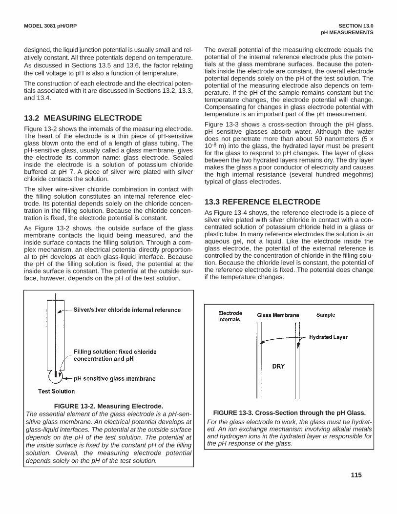
115
MODEL 3081 pH/ORP SECTION 13.0 pH MEASUREMENTS
designed, the liquid junction potential is usually small and rel-atively constant. All three potentials depend on temperature.As discussed in Sections 13.5 and 13.6, the factor relatingthe cell voltage to pH is also a function of temperature.The construction of each electrode and the electrical poten-tials associated with it are discussed in Sections 13.2, 13.3,and 13.4.
13.2 MEASURING ELECTRODEFigure 13-2 shows the internals of the measuring electrode.The heart of the electrode is a thin piece of pH-sensitiveglass blown onto the end of a length of glass tubing. ThepH-sensitive glass, usually called a glass membrane, givesthe electrode its common name: glass electrode. Sealedinside the electrode is a solution of potassium chloridebuffered at pH 7. A piece of silver wire plated with silverchloride contacts the solution.The silver wire-silver chloride combination in contact withthe filling solution constitutes an internal reference elec-trode. Its potential depends solely on the chloride concen-tration in the filling solution. Because the chloride concen-tration is fixed, the electrode potential is constant.As Figure 13-2 shows, the outside surface of the glassmembrane contacts the liquid being measured, and theinside surface contacts the filling solution. Through a com-plex mechanism, an electrical potential directly proportion-al to pH develops at each glass-liquid interface. Becausethe pH of the filling solution is fixed, the potential at theinside surface is constant. The potential at the outside sur-face, however, depends on the pH of the test solution.
The overall potential of the measuring electrode equals thepotential of the internal reference electrode plus the poten-tials at the glass membrane surfaces. Because the poten-tials inside the electrode are constant, the overall electrodepotential depends solely on the pH of the test solution. Thepotential of the measuring electrode also depends on tem-perature. If the pH of the sample remains constant but thetemperature changes, the electrode potential will change.Compensating for changes in glass electrode potential withtemperature is an important part of the pH measurement.Figure 13-3 shows a cross-section through the pH glass.pH sensitive glasses absorb water. Although the waterdoes not penetrate more than about 50 nanometers (5 x10⁻⁸ m) into the glass, the hydrated layer must be presentfor the glass to respond to pH changes. The layer of glassbetween the two hydrated layers remains dry. The dry layermakes the glass a poor conductor of electricity and causesthe high internal resistance (several hundred megohms)typical of glass electrodes.
13.3 REFERENCE ELECTRODEAs Figure 13-4 shows, the reference electrode is a piece ofsilver wire plated with silver chloride in contact with a con-centrated solution of potassium chloride held in a glass orplastic tube. In many reference electrodes the solution is anaqueous gel, not a liquid. Like the electrode inside theglass electrode, the potential of the external reference iscontrolled by the concentration of chloride in the filling solu-tion. Because the chloride level is constant, the potential ofthe reference electrode is fixed. The potential does changeif the temperature changes.
FIGURE 13-2. Measuring Electrode. The essential element of the glass electrode is a pH-sen-sitive glass membrane. An electrical potential develops atglass-liquid interfaces. The potential at the outside surfacedepends on the pH of the test solution. The potential atthe inside surface is fixed by the constant pH of the fillingsolution. Overall, the measuring electrode potentialdepends solely on the pH of the test solution.
FIGURE 13-3. Cross-Section through the pH Glass.For the glass electrode to work, the glass must be hydrat-ed. An ion exchange mechanism involving alkalai metalsand hydrogen ions in the hydrated layer is responsible forthe pH response of the glass.

116
MODEL 3081 pH/ORP SECTION 13.0 pH MEASUREMENTS
FIGURE 13-5. The Origin of Liquid Junction Potentials.The figure shows a thin section through a pore in the junction plug. The junction separates a solution of potassium chloride onthe left from a solution of hydrochloric acid on the right. The solutions have equal molar concentration. Driven by concentrationdifferences, hydrogen ions and potassium ions diffuse in the directions shown. The length of each arrow indicates relative rates.Because hydrogen ions move faster than potassium ions, positive charge builds up on the left side of the section and negativecharge builds up on the right side. The ever-increasing positive charge repels hydrogen and potassium ions. The ever-increas-ing negative charge attracts the ions. Therefore, the migration rate of hydrogen decreases, and the migration rate of potassi-um increases. Eventually the rates become equal. Because the chloride concentrations are the same, chloride does not influ-ence the charge separation or the liquid junction potential.
13.4 LIQUID JUNCTION POTENTIALThe salt bridge (see Figure 13-4) is an integral part of the ref-erence electrode. It provides the electrical connectionbetween the reference electrode and the liquid being meas-ured. Salt bridges take a variety of forms, anything from aglass frit to a wooden plug. Salt bridges are highly porous,and the pores are filled with ions. The ions come from the fill-ing solution and the sample. Some bridges permit only diffu-sion of ions through the junction. In other designs, a slowoutflow of filling solution occurs. Migration of ions in thebridge generates a voltage, called the liquid junction poten-tial. The liquid junction potential is in series with the measur-ing and reference electrode potentials and is part of the over-all cell voltage.
Figure 13-5 helps illustrate how liquid junction potentialsoriginate. The figure shows a section through a pore in thesalt bridge. For simplicity, assume the bridge connects asolution of potassium chloride and hydrochloric acid of equalmolar concentration. Ions from the filling solution and ions
from the sample diffuse through the pores. Diffusion is driv-en by concentration differences. Each ion migrates fromwhere its concentration is high to where its concentration islow. Because ions move at different rates, a charge separa-tion develops. As the charge separation increases, electro-static forces cause the faster moving ions to slow down andthe slower moving ions to speed up. Eventually, the migra-tion rates become equal, and the system reaches equilibri-um. The amount of charge separation at equilibrium deter-mines the liquid junction potential.Liquid junction potentials exist whenever dissimilar elec-trolyte solutions come into contact. The magnitude of thepotential depends on the difference between the mobility ofthe ions. Although liquid junction potentials cannot be elim-inated, they can be made small and relatively constant. Asmall liquid junction potential exists when the ions presentin greatest concentration have equal (or almost equal)mobilities. The customary way of reducing junction poten-tials is to fill the reference electrode with concentratedpotassium chloride solution. The high concentrationensures that potassium chloride is the major contributor tothe junction potential, and the nearly equal mobilities ofpotassium and chloride ions makes the potential small.
13.5 CONVERTING VOLTAGE TO pHEquation 1 summarizes the relationship between meas-ured cell voltage (in mV), pH, and temperature (in Kelvin):
E(T) = E°(T) + 0.1984 T pH (1)The cell voltage, E(T)—the notation emphasizes thedependence of cell voltage on temperature—is the sum offive electrical potentials. Four are independent of the pH ofthe test solution and are combined in the first term, E°(T).These potentials are listed below:1. the potential of the reference electrode inside the glass
electrode2. the potential at the inside surface of the glass mem-
brane3. the potential of the external reference electrode
FIGURE 13-4. Reference Electrode.The fixed concentration of chloride inside the electrodekeeps the potential constant. A porous plug salt bridge atthe bottom of the electrode permits electrical contactbetween the reference electrode and the test solution.

117
MODEL 3081 pH/ORP SECTION 13.0 pH MEASUREMENTS
4. the liquid junction potential.The second term, 0.1984 T pH, is the potential (in mV) atthe outside surface of the pH glass. This potential dependson temperature and on the pH of the sample. Assumingtemperature remains constant, any change in cell voltage iscaused solely by a change in the pH of the sample.Therefore, the cell voltage is a measure of the sample pH.Note that a graph of equation 1, E(T) plotted against pH, is astraight line having a y-intercept of E°(T) and a slope of0.1984 T.
13.6 GLASS ELECTRODE SLOPEFor reasons beyond the scope of this discussion, equation1 is commonly rewritten to remove the temperaturedependence in the intercept and to shift the origin of theaxes to pH 7. The result is plotted in Figure 13-6. Two linesappear on the graph. One line shows how cell voltagechanges with pH at 25°C, and the other line shows the rela-tionship at 50°C. The lines, which are commonly calledisotherms, intersect at the point (pH 7, 0 mV). An entirefamily of curves, each having a slope determined by thetemperature and all passing through the point (pH 7, 0 mV)can be drawn on the graph.
Figure 13-6 shows why temperature is important in making pHmeasurements. When temperature changes, the slope of theisotherm changes. Therefore, a given cell voltage correspondsto a different pH value, depending on the temperature. Forexample, assume the cell voltage is -150 mV. At 25°C the pHis 9.54, and at 50°C the pH is 9.35. The process of select-ing the correct isotherm for converting voltage to pH iscalled temperature compensation. All modern process pH
meters, including the Model 3081pH/ORP transmitter,have automatic temperature compensation.The slope of the isotherm is often called the glass electrodeor sensor slope. The slope can be calculated from theequation: slope = 0.1984 (t + 273.15), where t is tempera-ture in °C. The slope has units of mV per unit change in pH.The table lists slopes for different temperatures.
Temp (°C) Slope (mV/unit pH)15 -57.220 -58.225 -59.230 -60.135 -61.1
As the graph in Figure 13-6 suggests, the closer the pH isto 7, the less important is temperature compensation. Forexample, if the pH is 8 and the temperature is 30°C, a 10°Cerror in temperature introduces a pH error of ±0.03. At pH10, the error in the measured pH is ±0.10.
13.7 BUFFERS AND CALIBRATIONFigure 13-6 shows an ideal cell: one in which the voltage iszero when the pH is 7, and the slope is 0.1984 T over theentire pH range. In a real cell the voltage at pH 7 is rarelyzero, but it is usually between -30 mV and +30 mV. Theslope is also seldom 0.1984 T over the entire range of pH.However, over a range of two or three pH units, the slope isusually close to ideal.Calibration compensates for non-ideal behavior. Calibrationinvolves the use of solutions having exactly know pH, calledcalibration buffers or simply buffers. Assigning a pH value toa buffer is not a simple process. The laboratory work isdemanding, and extensive theoretical work is needed tosupport certain assumptions that must be made. Normally,establishing pH scales is a task best left to national stan-dards laboratories. pH scales developed by the UnitedStates National Institute of Standards and Technology(NIST), the British Standards Institute (BSI), the JapanStandards Institute (JSI), and the German DeutscheInstitute für Normung (DIN) are in common use. Althoughthere are some minor differences, for practical purposes thescales are identical. Commercial buffers are usually trace-able to a recognized standard scale. Generally, commercialbuffers are less accurate than standard buffers. Typicalaccuracy is ±0.01 pH units. Commercial buffers, sometimescalled technical buffers, do have greater buffer capacity.They are less susceptible to accidental contamination anddilution than standard buffers. Figure 13-7 shows graphically what happens during cali-bration. The example assumes calibration is being done at
FIGURE 13-6. Glass Electrode Slope.The voltage of a pH measurement cell depends on pH andtemperature. A given pH produces different voltagesdepending on the temperature. The further from pH 7, thegreater the influence of temperature on the relationshipbetween pH and cell voltage.

118
MODEL 3081 pH/ORP SECTION 13.0 pH MEASUREMENTS
pH 7.00 and pH 10.00. When the electrodes are placed inpH 7 buffer the cell voltage is V7, and when the electrodesare placed in pH 10 buffer, the cell voltage is V10. Note thatV7 is not 0 mV as would be expected in an ideal sensor, butis slightly different. The microprocessor calculates the equation of the straightline connecting the points. The general form of the equationis:
E = A + B (t + 273.15) (pH - 7) (2)The slope of the line is B (t + 273.15), where t is the tem-perature in °C, and the y-intercept is A. If pH 7 buffer isused for calibration, V7 equals A. If pH 7 buffer is not used,A is calculated from the calibration data.
The microprocessor then converts subsequent cell voltagemeasurements into pH using the calibration line.
13.8 ISOPOTENTIAL pHFrequently, the calibration temperature and the processtemperature are different. Therefore, the calibration slopeis not appropriate for the sample. Figure 13-7 shows whatthe microprocessor does when buffer and sample temper-atures are different. Assume the sensor was calibrated attemperature t1 and the process temperature is t2. To meas-ure the pH of the process, the microprocessor rotates thecalibration line about the point (pH 7, A) until the slopeequals B (t2 + 273.15). The microprocessor then uses thenew isotherm to convert voltage to pH. The point (pH 7, A)is called the isopotential pH. As Figure 13-7 shows, theisopotential pH is the pH at which the cell voltage does notchange when the temperature changes.
The microprocessor makes assumptions when the meas-urement and calibration temperatures are different. Itassumes the actual measurement cell isotherms rotateabout the point (pH 7, A). The assumption may not be cor-rect, so the measurement will be in error. The size of theerror depends on two things: the difference between theisopotential pH of the measurement cell and pH 7 and thedifference between the calibration and measurement tem-peratures. For a 10°C temperature difference and a differ-ence in isopotential pH of 2, the error is about ±0.07 pHunits. The factors that cause the isopotential pH of a realcell to differ from 7 are beyond the scope of this discussionand to a great extent are out of the control of the user aswell.Most pH cells do not have an isopotential pH point. Instead,the cell isopotential pH changes with temperature, and thecell isotherms rotate about a general area. Measuring theisopotential pH requires great care and patience.One way to reduce the error caused by disagreementbetween the sensor and meter isopotential pH is to cali-brate the sensor at the same temperature as the process.However, great care must be exercised when the buffertemperature is significantly greater than ambient tempera-ture. First, the buffer solution must be protected from evap-oration. Evaporation changes the concentration of thebuffer and its pH. Above 50°C, a reflux condenser may benecessary. Second, the pH of buffers is defined over a lim-ited temperature range. For example, if the buffer pH isdefined only to 60°C, the buffer cannot be used for calibra-tion at 70°C. Finally, no matter what the temperature, it isimportant that the entire measurement cell, sensor andsolution, be at constant temperature. This requirement iscritical because lack of temperature uniformity in the cell isone reason the cell isopotential point moves when the tem-perature changes.
13.9 JUNCTION POTENTIAL MISMATCHAlthough glass electrodes are always calibrated withbuffers, the use of buffers causes a fundamental error inthe measurement.When the glass and reference electrodes are placed in abuffer, a liquid junction potential, Elj, develops at the inter-face between the buffer and the salt bridge. The liquid junc-tion potential is part of the overall cell voltage and is includ-ed in A in equation 2. Equation 2 can be modified toshow Elj, as a separate term:
E = A’ + Elj + B (t + 273.15) (pH - 7) (3)or
E = E’ (pH, t) + Elj (4)where E’ (pH, t) = A’ + B (t + 273.15) (pH - 7).In Figure 13-8, calibration and measurement data are plot-ted in terms of equation 4. The cell voltage, E, is repre-sented by the dashed vertical line. The contribution of eachterm in equation 4 to the voltage is also shown. The liquid
FIGURE 13-7. Two-Point Buffer Calibration.The graph shows a calibration using pH 7 and pH 10 buffers.The calibration equation is the straight line connecting the twopoints. If temperature changes, the slope changes by the ratio(t2 + 273.15)/(t1 + 273.15), where t1 is the calibration tempera-ture and t2 is the process temperature in °C. The calibrationequations rotate about the point (pH 7, A).
t1t2
(pH10, V10)
(pH7, V7)

119
MODEL 3081 pH/ORP SECTION 13.0 pH MEASUREMENTS
junction potentials in the buffers are assumed to be equaland are exaggerated for clarity.If the liquid junction potential in the sample differs from thebuffers, a measurement error results. Figure 13-8 illus-trates how the error comes about. Assume the true pH ofthe sample is pHs and the cell voltage is Es. The point (pHs,Es) is shown on the graph. If the liquid junction potential inthe sample were equal to the value in the buffers, the pointwould lie on the line. However, the liquid junction potentialin the sample is greater, so the point Es lies above the cal-ibration line. Therefore, when the cell voltage is convertedto pH, the result is greater than the true pH by the amountshown.A typical mismatch between liquid junction potentials inbuffer and sample is 2-3 mV, which is equivalent to an errorof about ±0.02 pH units. The mismatch produces a funda-mental error in pH determinations using a cell with liquidjunction.
13.10 SENSOR DIAGNOSTICSSensor diagnostics alert the user to problems with the sen-sor or to actual sensor failures. The two sensor diagnosticsare reference impedance and glass impedance.The major contributor to reference impedance is the resist-ance across the liquid junction plug. In a properly function-ing electrode, the resistance of the liquid junction should beno more than several hundred kilohms. If the junction isplugged or if the filling solution or gel is depleted, the resist-ance increases. A high reference impedance may alsomean the sensor is not immersed in the process stream.Glass impedance refers to the impedance of the pH-sensi-tive glass membrane. The impedance of the glass mem-brane is a strong function of temperature. As temperatureincreases, the impedance decreases. For a change inglass impedance to have any meaning, the impedancemeasurement must be corrected to a reference tempera-ture. The impedance of a typical glass electrode at 25°C isseveral hundred megohms. A sharp decrease in the tem-perature-corrected impedance implies that the glass iscracked. A cracked glass electrode produces erroneous pHreadings. The electrode should be replaced immediately. Ahigh temperature-corrected glass impedance implies thesensor is nearing the end of its life and should be replacedas soon as possible.
13.11 SHIELDS, INSULATION, AND PREAMPLIFIERS
pH measurement systems, cell and meter, have highimpedance. The high impedance circuit imposes importantrestrictions on how pH measurement systems aredesigned.The lead wire from the glass electrode connects two highresistances: about 100 MΩ at the electrode and about1,000,000 MΩ at the meter. Therefore, electrostaticcharges, which accumulate on the wire from environmentalinfluences, cannot readily drain away. Buildup of chargeresults in degraded, noisy readings. Shielding the wire withmetal braid connected to ground at the instrument is oneway to improve the signal. It is also helpful to keep the sen-sor cable as far away as possible from AC power cables.The high input impedance of the pH meter requires that thelead insulation and the insulation between the meter inputsbe of high quality. To provide further protection from envi-ronmental interference, the entire sensor cable can beenclosed in conduit.To avoid the need for expensive cable and cable installa-tions, a preamplifier built into the sensor or installed in ajunction box near the sensor can be used. The preamplifi-er converts the high impedance signal into a low imped-ance signal that can be sent as far as 200 feet without spe-cial cable.
FIGURE 13-8. Liquid Junction Potential Mismatch.The dashed vertical lines are the measured cell voltages forthe buffers and the sample. The contribution from eachterm in equation 4 is shown. The buffers are are assumedto have identical liquid junction potentials. Because mostbuffers are equitransferant, i.e., the mobilities of the ionsmaking up the buffer are nearly equal, assuming equal liq-uid junction potentials is reasonable. In the figure, the liquidjunction potential of the sample is greater than the buffers.The difference gives rise to an error in the measured pH.

120
MODEL 3081 pH/ORP SECTION 14.0 ORP MEASUREMENTS
SECTION 14.0ORP MEASUREMENTS
14.1 General14.2 Measuring Electrode14.3 Reference Electrode14.4 Liquid Junction Potential14.5 Relating Cell Voltage to ORP14.6 ORP, Concentration, and pH14.7 Interpreting ORP Measurements14.8 Calibration
14.1 GENERALFigure 14-1 shows a simplified diagram of an electrochemical cell that can be used to determine the oxidation-reduction potential or ORP of a sample. The cell consists of a measuring electrode, a reference electrode, the liq-uid being measured, and a temperature-sensing element. The cell voltage is the ORP of the sample. In most indus-trial and scientific applications, a pH meter is used to measure the voltage. Because a pH meter is really a highimpedance voltmeter, it makes an ideal ORP meter.
Figure 14-1 shows separate measuring and reference electrodes. In most process sensors the electrodes and thetemperature element are combined into a single body. Such sensors are often called combination electrodes.
The cell voltage is the algebraic sum of the potential of the measuring electrode, the potential of the reference elec-trode, and the liquid junction potential. The potential of the measuring electrode depends on the ORP of the solu-tion. The potential of the reference electrode is unaffected by ORP, so it provides a stable reference voltage. Theliquid junction potential depends in a complex way on the identity and concentration of the ions in the sample. It isalways present, but if the sensor is properly designed, the liquid junction potential is usually small and relativelyconstant. All three potentials depend on temperature.
The construction of each electrode and the electrical potential associated with the electrode are discussed inSections 14.2, 14.3, and 14.4.
FIGURE 14-1. ORP Measurement Cell. The cell consists of a measuring and reference electrode. The voltage between the elec-trodes is the ORP of the test solution. Because ORP depends on temperature, the tempera-ture at which the measurement is made must be reported.
Voltmeter

121
14.2 MEASURING ELECTRODEFigure 14-2 shows a typical ORP measuring elec-trode. The electrode consists of a band or disc ofplatinum attached to the base of a sealed glass tube.A platinum wire welded to the band connects it to thelead wire.
For a noble metal electrode to develop a stablepotential, a redox couple must be present. A redoxcouple is simply two compounds that can be con-verted into one another by the gain or loss of elec-trons. Iron (II) and iron (III) are a redox couple. Theoxidized form, iron (III), can be converted into thereduced form, iron (II), by the gain of one electron.Similarly, iron (II) can be converted to iron (III) by theloss of an electron. For more details concerning thenature of redox potential, see Section 14.5.
14.3 REFERENCE ELECTRODEAs Figure 14-3 shows, the reference electrode is apiece of silver wire plated with silver chloride in con-tact with a concentrated solution of potassium chlo-ride held in a glass or plastic tube. In many referenceelectrodes the solution is an aqueous gel, not a liquid.The potential of the reference electrode is controlledby the concentration of chloride in the filling solution.Because the chloride level is constant, the potential ofthe reference electrode is fixed. The potential doeschange if the temperature changes.
14.4 LIQUID JUNCTION POTENTIALA salt bridge (see Figure 14-3) is an integral part of thereference electrode. It provides the electrical connec-tion between the reference electrode and the liquidbeing measured. Salt bridges take a variety of forms,anything from a glass frit to a wooden plug. Saltbridges are highly porous and the pores are filled withions. The ions come from the filling solution and thesample. Some bridges permit only diffusion of ionsthrough the junction. In other designs, a slow outflowof filling solution occurs. Migration of ions in the bridgegenerates a voltage, called the liquid junction poten-tial. The liquid junction potential is in series with themeasuring and reference electrode potentials and ispart of the overall cell voltage. Figure 14-4 helps illustrate how liquid junction poten-tials originate. The figure shows a section through apore in the salt bridge. For simplicity, assume thebridge connects a solution of potassium chloride andhydrochloric acid of equal molar concentration. Ionsfrom the filling solution and ions from the sample dif-fuse through the pores. Diffusion is driven by concen-tration differences. Each ion migrates from where itsconcentration is high to where its concentration is low.Because ions move at different rates, a charge sepa-ration develops. As the charge separation increases,electrostatic forces cause the faster moving ions toslow down and the slower moving ions to speed up.Eventually, the migration rates become equal, and thesystem reaches equilibrium. The amount of chargeseparation at equilibrium determines the liquid junctionpotential.
MODEL 3081 pH/ORP SECTION 14.0 ORP MEASUREMENTS
FIGURE 14-2. Measuring Electrode. An ORP electrode is a piece of noble metal, usual-ly platinum, but sometimes gold, attached to theend of a glass tube. The potential of the electrodeis controlled by the ratio of oxidized to reduced sub-stances in the sample. pH and other constituents inthe sample may also affect ORP.
FIGURE 14-3. Reference Electrode.The fixed concentration of chloride inside the elec-trode keeps the potential constant. A porous plugsalt bridge at the bottom of the electrode permitselectrical contact between the reference electrodeand the test solution.

122
Liquid junction potentials exist whenever dissimilar elec-trolyte solutions come into contact. The magnitude of thepotential depends on the difference between the mobility ofthe ions. Although liquid junction potentials cannot be elim-inated, they can be made small and relatively constant. Asmall liquid junction potential exists when the ions presentin greatest concentration have equal (or almost equal)mobilities. The customary way of reducing junction poten-tials is to fill the reference electrode with concentratedpotassium chloride solution. The high concentrationensures that potassium chloride is the major contributor tothe junction potential, and the nearly equal mobilities ofpotassium and chloride ions makes the potential small.
14.5 RELATING CELL VOLTAGE TO ORPThe measured cell voltage, E(T)—the notation emphasizesthe temperature dependence—is the algebraic sum of themeasuring (platinum) electrode potential, the referenceelectrode potential, and the liquid junction potential.Because the potential of the reference electrode is inde-pendent of ORP and the liquid junction potential is small,the measured cell voltage is controlled by the ORP of thesample. Stated another way, the cell voltage is the ORP ofthe sample relative to the reference electrode.
14.6 ORP, CONCENTRATION, AND pHORP depends on the relative concentration of oxidized andreduced substances in the sample and on the pH of thesample. An understanding of how concentration and pHinfluence ORP is necessary for the correct interpretation ofORP readings.
Figure 14-5 shows a platinum ORP electrode in contactwith a solution of iron (II) and iron (III). As discussed earli-er, iron (II) and iron (III) are a redox couple. They are relat-ed by the following half reaction:
Fe+3 + e- = Fe+2 (1)
If a redox couple is present, a stable electrical potentialeventually develops at the interface between the platinumelectrode and the sample. The magnitude of the potential
MODEL 3081 pH/ORP SECTION 14.0 ORP MEASUREMENTS
FIGURE 14-4. The Origin of Liquid Junction Potentials.The figure shows a thin section through a pore in the junction plug. The junction separates a solution of potassium chlorideon the left from a solution of hydrochloric acid on the right. The solutions have equal molar concentration. Driven by con-centration differences, hydrogen ions and potassium ions diffuse in the directions shown. The length of each arrow indicatesrelative rates. Because hydrogen ions move faster than potassium ions, positive charge builds up on the left side of the sec-tion and negative charge builds up on the right side. The ever-increasing positive charge repels hydrogen and potassiumions. The ever-increasing negative charge attracts the ions. Therefore, the migration rate of hydrogen decreases, and themigration rate of potassium increases. Eventually the rates become equal. Because the chloride concentrations are thesame, chloride does not influence the charge separation or the liquid junction potential.
FIGURE 14-5. Electrode Potential.The drawing shows an iron (II) and iron (III) ion at the sur-face of a platinum electrode. Iron (III) can take an electronfrom the platinum and be reduced, and iron (II) can placean electron on the metal and be oxidized. The electrodepotential is the tendency of the half reaction shown in thefigure to occur spontaneously. Because the voltmeterused to measure ORP draws almost no current, there isno change in the concentration of iron (II) and iron (III) atthe electrode.

123
is described by the following equation, called theNernst equation:
E = E° - (2)
In the Nernst equation, E is the electrode potential andE° is the standard electrode potential, both in millivolts,t is temperature in °C, n is the number of electronstransferred (n = 1 in the present case), and [Fe+2] and[Fe+3] are the concentrations of iron (II) and iron (III)respectively. There are several ways of defining thestandard electrode potential, E°. No matter which defi-nition is used, the standard electrode potential is sim-ply the electrode potential when the concentrations ofiron (II) and iron (III) have defined standard values.
Equation 2 shows that the electrode potential is con-trolled by the logarithm of the ratio of the concentrationof iron (II) to iron (III). Therefore, at 25°C if the ratiochanges by a factor of ten, the electrode potentialchanges by
- log 10 = - 59.2 mV
As the expression above shows, the voltage change isalso directly proportional to temperature and inverselyproportional to the number of electrons transferred.
14.7 INTERPRETING ORP MEASUREMENTSInterpreting ORP and changes in ORP requires greatcaution. There are several concepts to keep in mindconcerning industrial ORP measurements.
• ORP is best used to track changes in concentration orto detect the presence or absence of certain chemicals.For example, in the treatment of wastes from metal fin-ishing plants, chromium (VI) is converted to chromium(III) by treatment with sulfur dioxide. Because chromium(VI) and chromium (III) are a redox couple, ORP can beused to monitor the reaction. As sulfur dioxide convertschromium (VI) to chromium (III), the concentration ratiochanges and the ORP drops. Once all the chromium(VI) has been converted to chromium (III) and a slightexcess of sulfur dioxide is present, the chromium cou-ple no longer determines ORP. Instead, ORP is con-trolled by the sulfur dioxide-sulfate couple. When sulfurdioxide reacts with chromium (VI), it is converted to sul-fate. Figure 14-6 shows how ORP and the concentra-tion of chromium (VI) change as sulfur dioxide is added.Because the change in ORP at the endpoint is large,monitoring ORP is an efficient way of tracking theprocess.
• ORP measures activity, not concentration. Activityaccounts for the way in which other ions in solutioninfluence the behavior of the redox couple being meas-ured. To be strictly correct, ORP is controlled by the theratio of activities, not concentrations. The dependenceof ORP on activity has an important consequence.Suppose a salt, like sodium sulfate, is added to a solu-tion containing a redox couple, for example iron (II) andiron (III). The sodium sulfate does not change the con-centration of either ion. But, the ORP of the solutiondoes change because the salt alters the ratio of theactivity of the ions.
• pH can have a profound influence on ORP. Referringto the earlier example where ORP was used to monitorthe conversion of chromium (VI) to chromium (III). Thereaction is generally carried out at about pH 2.Because the concentration ratio in the Nernst equationalso includes hydrogen ions, the ORP of a mixture ofchromium (VI) and chromium (III) is a function of pH.
To appreciate the extent to which pH influences ORP,consider the conversion of chromium (VI) to chromium(III). In acidic solution the half reaction is:
Cr2O7-2 + 14 H+ + 6 e- = 2 Cr+3 + 7 H2O (3)
• Chromium (VI) exists as dichromate, Cr2O7-2, inacidic solution.
MODEL 3081 pH/ORP SECTION 14.0 ORP MEASUREMENTS
FIGURE 14-6. ORP Measurement Interpretation
0.1987 (t + 273.15) log [Fe+2]n [Fe+3]
0.1987 (25 + 273.15)1
Sulfur dioxide added
Cr (VI)
OR
P, m
V
Chr
omiu
m (V
I), p
pm

124
The Nernst equation for reaction 3 is:
E = E°- (4)
Note that the hydrogen ion factor in the concentrationratio is raised to the fourteenth power. The table showsthe expected effect of changing pH on the measuredORP at 25°C.
pH changes ORP changes by
from 2.0 to 2.2 7 mV
from 2.0 to 2.4 35 mV
from 2.0 to 1.8 47 mV
from 2.0 to 1.6 75 mV
The Nernst equation can be written for any half reaction.However, not all half reactions behave exactly as predict-ed by the Nernst equation. Why real systems do not actas expected is beyond the scope of this discussion. Thepotential of chromium (VI) - chromium (III) couple used asan example above does not perfectly obey the Nernstequation. However, the statement that pH has a strongeffect on the electrode potential of the couple is true.
• As mentioned earlier, ORP is best suited for measur-ing changes, not absolute concentrations. If ORP isused to determine concentration, great care should beexercised. An example is the determination of chlorinein water. When water is disinfected by treatment withchlorine gas or sodium hypochlorite, free chlorineforms. Free chlorine is a mixture of hypochlorous acid(HOCl) and hypochlorite ions (OCl-). The relativeamount of hypochlorous acid and hypochlorite presentdepends on pH. For disinfection control, total free chlo-rine, the sum of hypochlorous acid and hypochloriteion, is important. Equation 5 shows the half reaction forhypochlorous acid:
HOCl + H+ + 2e¯ = Cl¯ + H2O (5)
The Nernst equation is
E = E° - (6)
Only the concentration of hypochlorous acid appears inthe Nernst equation. To use ORP to determine totalfree chlorine, equation 6 must be rewritten in terms of
free chlorine. Although the details are beyond the scopeof this discussion, the result is shown in equation 7:
E = E° - (7)
where K is the acid dissociation constant for hypochlor-ous acid (2.3 x 10⁻⁸) and Ca is the total free chlorineconcentration. As equation 7 shows the measuredORP depends on the hydrogen ion concentration (i.e.,pH), the chloride concentration, the free chlorine con-centration, and temperature. Therefore, for ORP to bea reliable measurement of free chlorine, pH, chloride,and temperature must be reasonably constant.
Assume the free chlorine level is 1.00 ppm and thechloride concentration is 100 ppm. The table showshow slight changes in pH influence the ORP.
pH changes ORP changes by
from 8.0 to 7.8 3.9 mV
from 8.0 to 7.6 7.1 mV
from 8.0 to 8.2 4.4 mV
from 8.0 to 8.4 9.2 mV
Around pH 8 and 1.00 ppm chlorine, a change in ORPof 1.4 mV corresponds to a change in chlorine level ofabout 0.1 ppm. Therefore, if pH changed only 0.2 unitsand the true chlorine level remained constant at 1.00ppm, the apparent chlorine level (determined by ORP)would change about 0.3 ppm.
14.8 CALIBRATIONAlthough there is no internationally recognized ORPcalibration standard, the iron (II) - iron (III) coupleenjoys some popularity. The standard is a solution of0.1 M iron (II) ammonium sulfate and 0.1 M iron (III)ammonium sulfate in 1 M sulfuric acid. The solutionhas good resistance to air oxidation. If stored in a tight-ly closed container, the shelf life is one year. Becausethe standard contains equal amounts of iron (II) andiron (III), the ORP does not change appreciably if thesolution becomes slightly diluted. In addition, minorvariability in actual concentration does not affect thestandard ORP.
MODEL 3081 pH/ORP SECTION 14.0 ORP MEASUREMENTS
0.1987 (t + 273.15) log [Cr+3] 2
6 [Cr2O7-2] [H+]14
0.1987 (t + 273.15) log [Cl-] 2 [HOCl] [H+]
0.1987 (t + 273.15) log [Cl-] [H+] + K2 Ca [H+] 2

125
MODEL 3081 pH/ORP SECTION 14.0 ORP MEASUREMENTS
The ORP of the iron (II) - iron (III) standard when meas-ured with a platinum electrode against a saturated sil-ver-silver chloride reference is 476 ± 20 mV at 25°C.The range of values is caused primarily by the high andvariable liquid junction potential generated in solutionscontaining high acid concentrations.
Quinhydrone - hydroquinone ORP standards are alsoused. They are prepared by dissolving excess quinhy-drone in either pH 4.00 or pH 6.86 buffer. The ORP ofthe standards at a platinum electrode against a silver -silver chloride reference has been measured at 20°C,25°C, and 30°C.
Temperature ORP in ORP in pH 4.00 buffer pH 6.86 buffer
20°C 268 mV 92 mV
25°C 263 mV 86 mV
30°C 258 mV 79 mV
There are two disadvantages to using quinhydronestandards. First, the shelf life is only about eight hours,so fresh standard must be prepared daily. Second,hydroquinone is highly toxic, so preparing, handling,and disposing of the standards requires care.
Unlike pH calibrations, which are generally done usingtwo calibration buffers, ORP calibrations are almostalways single point calibrations.

126
15.1 OVERVIEW OF HART COMMUNICATIONHART (highway addressable remote transducer) is a digital communication system in which two frequencies aresuperimposed on the 4 to 20 mA output signal from the transmitter. A 1200 Hz sine wave represents the digit 1,and a 2400 Hz sine wave represents the digit 0. Because the average value of a sine wave is zero, the digital sig-nal adds no dc component to the analog signal. HART permits digital communication while retaining the analogsignal for process control.
The HART protocol, originally developed by Fisher-Rosemount, is now overseen by the independent HARTCommunication Foundation. The Foundation ensures that all HART devices can communicate with one another.For more information about HART communications, call the HART Communication Foundation at (512) 794-0369.The internet address is http://www.hartcomm.org.
15.2 HART INTERFACE DEVICESHART communicators allow the user to view measurement data (pH, ORP and temperature), program the transmit-ter, and download information from the transmitter for transfer to a computer for analysis. Downloaded informationcan also be sent to another HART transmitter. Either a hand-held communicator, such as the Rosemount Model 275,or a computer can be used. HART interface devices operate from any wiring termination point in the 4 - 20 mA loop.A minimum load of 250 ohms must be present between the transmitter and the power supply. See Figure 15-1.
MODEL 3081 pH/ORP SECTION 15.0THEORY - REMOTE COMMUNICATIONS
SECTION 15.0THEORY - REMOTE COMMUNICATIONS
15.1 Overview of HART Communications15.2 HART Interface Devices15.3 AMS Communication
4-20 mA + Digital250 ohm
Control System
Computer
Model 3081 pH Smart
Transmitter
BridgeHand Held
Communicator(“Configurator”)
FIGURE 15-1. HART Communicators. Both the Rosemount Model 275 and a computer can be used to communicate with aHART transmitter. The 250 ohm load (minimum) must be present between the transmit-ter and the power supply.

127
MODEL 3081 pH/ORP SECTION 15.0THEORY - REMOTE COMMUNICATIONS
If your communicator does not recognize the Model 3081 pH/ORP transmitter, the device description library may needupdating. Call the manufacturer of your HART communication device for updates.
15.3 ASSET MANAGEMENT SOLUTIONSAsset Management Solutions (AMS) is software that helps plant personnel better monitor the performance of analyticalinstruments, pressure and temperature transmitters, and control valves. Continuous monitoring means maintenance per-sonnel can anticipate equipment failures and plan preventative measures before costly breakdown maintenance isrequired. AMS uses remote monitoring. The operator, sitting at a computer, can view measurement data, change program settings,read diagnostic and warning messages, and retrieve historical data from any HART-compatible device, including the Model3081 pH/ORP transmitter. Although AMS allows access to the basic functions of any HART compatible device, RosemountAnalytical has developed additional software for that allows access to all features of the Model 3081 pH/ORP transmitter.AMS can play a central role in plant quality assurance and quality control. Using AMS Audit Trail, plant operators can trackcalibration frequency and results as well as warnings and diagnostic messages. The information is available to Audit Trailwhether calibrations were done using the infrared remote controller, the Model 275 HART communicator, or AMS software. AMS operates in Windows 95. See Figure 15-2 for a sample screen. AMS communicates through a HART-compatiblemodem with any HART transmitters, including those from other manufacturers. AMS is also compatible withFOUNDATION™ Fieldbus, which allows future upgrades to Fieldbus instruments.For more information about AMS, including upgrades, renewals, and training, call Fisher-Rosemount Systems, Inc. at (612)895-2000.
FIGURE 15-2. AMS Main Menu Tools

128
TERM DEFINITIONAcid When dissolved in water acids increase the hydrogen ion concentration. Pure
water at 25°C contains 1 x 10⁻⁷ moles per liter of hydrogen ions (H+) and an equalconcentration of hydroxide ions (OH-). An acid increases the hydrogen ion con-centration above the value found in pure water and decreases the hydroxide ionconcentration. However, the product of the hydroxide and hydrogen concentra-tions remains constant.
Activity Physical and chemical measurements made in real solutions are usually differentfrom the values predicted from the behavior in ideal solutions. Activity is a way ofaccounting for the discrepancy. For ions in solution ideal behavior occurs at infi-nite dilution. Infinite dilution means the solution contains so few ions that theybehave independently of one another. As the concentration of the ions increase,they start to interact and the properties of the solution begin to deviate from theideal. The ratio of the true value to the ideal value at a given concentration is theactivity coefficient. The product of the activity coefficient and the concentration isthe activity. For electrolytes, the activity is always less than the concentration.
Alkalai metal The alkalai metals are lithium, sodium, potassium, and cesium. They form ionshaving unit positive charge. Ion exchange reactions involving alkalai metal ionscause certain types of glass to develop electrical potentials in the presence ofhydrogen ions.
AMS AMS is an acronym for Asset Management Solutions. AMS is software running inWindows 95 that allows the user, sitting at a computer, to view process measure-ments, program transmitters, and review maintenance and performance records.
Balco RTD The sensing element in a Balco RTD is an alloy containing 70% nickel and 30%iron. Balco RTDs are identified by their resistance at 25°C. The resistancechanges about +0.45% per °C.
Base When dissolved in water bases decrease the hydrogen ion concentration. Purewater at 25°C contains 1 x 10⁻⁷ moles per liter of hydrogen ions (H+) and an equalconcentration of hydroxide ions (OH-). A base decreases the hydrogen ion con-centration below the value found in pure water and increases the hydroxide ionconcentration. However, the product of the hydroxide and hydrogen concentra-tions remains constant. Alkalai is another word for base.
Buffer (calibration) A calibration buffer is a solution having accurately known pH. Calibration buffershave a nominal pH, which is the pH at 25°C. Changing the temperature changesthe pH value of a buffer. Buffers define the pH scale and are used to calibrate theresponse of pH measurement cells.
Buffer The term buffer generally refers to a solution that resists changes in pH upon dilu-tion or the addition of small amount of a strong acid or base.
Calibration Chemical sensors are transducers. They produce a signal related to concentra-tion or to a physical property. Calibration is the process of assigning known con-centrations or known physical values to the sensor signal. Because the relation-ship between sensor output and physical or chemical property is often linear, onlyone or two calibration points are needed.
MODEL 3081 pH/ORP SECTION 16.0GLOSSARY
SECTION 16.0GLOSSARY

129
MODEL 3081 pH/ORP SECTION 16.0GLOSSARY
Combination electrode In a combination electrode, the measuring electrode and reference electrode arecombined in a single body. Often the temperature element is included in the bodyas well.
Common A point in a circuit against which voltages are measured.
Diagnostics Diagnostics, also called advanced sensor diagnostics, automatically and continu-ously monitor the condition of the sensor. Diagnostics warn the user of impendingor existing problems with the sensor. The most useful pH sensor diagnostics areglass impedance and reference impedance.
Electrode potential Electrode potential is a measure of the tendency of a half reaction to occur as writ-ten. Electrode potentials are stated relative to a reference electrode, which byconvention is the normal hydrogen electrode. The normal hydrogen electrode isassigned a potential of zero volts.
Electrochemical cell An electrochemical cell consists of two half reactions occurring in separate con-tainers connected electrically by a salt bridge. The electrons produced by the oxi-dation half reaction are consumed by the reduction half reaction. Because theelectrons must pass through an external circuit, they can be made to do usefulwork. The drawing below shows a simple electrochemical cell.
The voltage of the electrochemical cell (measured without drawing current fromthe cell) is the algebraic sum of the potentials of the two electrodes.
Electrode Electrochemistry is the study of charge transfer across boundaries. The chargebeing transferred can be ions or electrons. An electrode is a two-phase systemwhere the charge transfer across the interface involves electrons. A real physicalelectrode may incorporate several boundaries.
Electrolyte An electrolyte is a substance that when dissolved in water produces an apprecia-ble concentration of ions. Most salts, mineral acids (sulfuric acid, hydrochloricacid, phosphoric acid, and nitric acid), and most bases are electrolytes.
Error Error is a measure of how closely a measured value agrees with the true value.In cases where a true value is not known, error usually refers to the differencebetween the measured and the generally accepted value.
Error condition An error condition (Std Err, SLOPE Err LO, or SLOPE Err HI) occurs during cali-bration if standardization offset or the slope exceeds programmed values.
Explosion proof An enclosure is explosion proof if it can withstand an internal explosion withoutrupturing and without causing the the ignition of the gas surrounding the enclo-sure.

130
MODEL 3081 pH/ORP SECTION 16.0GLOSSARY
Fault A fault is a system disabling condition. Measurement data displayed during a faultcondition are probably in error and should be regarded with great suspicion. TheModel 3081 pH/ORP transmitter displays fault messages to aid in trouble-shooting.
Filling solution The electrolyte solution inside an electrode is called the filling solution. Thebuffered electrolyte solution inside a glass electrode is usually called the internalfilling solution. The solution inside the reference electrode is usually called theexternal filling solution, or, simply, the filling solution. In many industrial referenceelectrodes, the filling solution is not a liquid but is a semi-solid gel. Glass imped-ance. The overall resistance of the glass membrane to the flow of current. Glassimpedance is a strong function of temperature. Impedance increases as temper-ature decreases. Temperature corrected glass impedance is a valuable diagnos-tic tool. Abnormally low impedance implies a cracked or broken glass membrane.High impedance suggests that the electrode is nearing the end of its life.
Glass electrode pH measuring electrodes are often called glass electrodes. The electrode is apiece of glass tubing that has a pH-sensitive glass membrane blown onto the end.The tube is filled with a buffered solution of potassium chloride. A silver wire coat-ed with silver chloride contacts the fill solution, and the silver wire is connected tothe electrode lead wire. The entire electrode is sealed."Glass" refers to the pH-sensitive glass membrane in the sensor.
Glass membrane The glass membrane is the pH-sensitive glass piece blown onto the bottom of theglass tube that forms the body of the glass electrode. The pH sensitive glass isusually a bulb, but it can be flat.
Ground Ground usually refers to either earth ground or a common. Earth ground is theearth or a conducting body serving in place of the earth. A common is a point ina circuit to which other voltages are compared. The meaning intended is usuallyclear from the context.
Ground loop A ground loop exists when a circuit is connected to earth ground at two or morepoints. The potential of the earth varies from point to point, so multiple connec-tions to ground cause currents to flow. If the current flows through a signal carry-ing wire, the result is a noisy, offset signal. In a typical process measurement, thepH sensor is connected through the process liquid to earth ground. If the circuit-ry in the pH transmitter becomes connected to a second earth ground, current willflow through the reference electrode. A voltage, proportional to the current and theelectrode resistance, develops across the reference electrode. Because the volt-age is in series with the other potentials in the cell, the ground loop current caus-es the pH reading to be substantially different from the expected value. pH read-ings affected by ground loops are often noisy as well.
Half reaction A half reaction shows the gain or loss of electrons by a chemical species. The halfreaction for a silver-silver chloride reference electrode is
AgCl (s) + e- = Ag (s) + Cl-
In the half reaction, a silver ion in the silver chloride crystal gains an electron andbecomes a silver atom. The electron consumed by the silver ion comes from asecond half reaction occurring elsewhere in the system.
HART HART is an acronym for highway addressable remote transducer. HART is a dig-ital communication system in which digital signals are superimposed on the 4-20mA output signal from the transmitter. Using a HART communicator connectedacross the output, the user can view process measurements and can calibrateand program the transmitter.

131
MODEL 3081 pH/ORP SECTION 16.0GLOSSARY
Hold function During hold the Model 3081 pH/ORP transmitter generates a pre-programmedoutput current or remains at the last value. Placing the transmitter in hold avoidsfalse alarms and unwanted operation of chemical dosing pumps while the sensoris being calibrated or cleaned.
Intrinsically safe An enclosure is intrinsically safe if a spark or heat generated during normal oper-ation or during a fault likely to occur in practice is incapable of igniting the gas,vapor, or dust surrounding the enclosure.
Isopotential pH The isopotential pH is the pH at which voltage is independent of temperature. Thetransmitter isopotential pH is 7.00. The isopotential pH of the measuring cell maybe different from 7.00. The greater the difference between the transmitter and cellisopotential pH, the greater the error when the calibration and measurement tem-peratures are different.
Isotherm A plot of cell voltage against pH is a straight line. The line is called an isotherm.When temperature changes, the slope of the isotherm changes. Therefore, thepH to which a given cell voltage corresponds depends on temperature. Meterisotherms intersect at the meter isopotential point. Isotherms for pH measurementcells rarely intersect at a single point, but they usually cross in a fairly small area.
Junction box Signal carrying wires are conveniently joined together in a junction box. Usuallythe box contains two terminal strips connected internally point to point. The wiresin one cable are terminated on one strip, and the wires in the other cable are ter-minated on the second strip. The point to point connection between the terminalstrips produces a point to point connection between the wires.
Liquid junction potential A liquid junction potential exists when two dissimilar electrolyte solutions comeinto contact but are not allowed to mix. The potential arises from the differentmobilities of the ions in the contacting solutions. Generally the solution of great-est concentration has the greatest influence on the size of the liquid junctionpotential. Although liquid junction potentials cannot be eliminated, they can bemade small and relatively constant if the concentrated solution contains ions ofequal or nearly equal mobilities.
Measuring electrode A measuring electrode is an electrode for which the potential is proportional to theconcentration or activity of the substance of interest.
Menu A menu contains the steps that allows the user to calibrate or program the Model3081pH/ORP transmitter or to read diagnostic messages.
Molar concentration Molar concentration is the number of moles of substance dissolved in one liter ofsolution. A mole is a measure of the quantity of ions, molecules, or atoms in a sub-stance.
Nernst equation The Nernst equation relates the potential of an electrode to the concentration oractivity of the chemical substances that appear in the half reaction occurring atthe electrode.
Non-incendive A non-incendive circuit is a circuit that is incapable of igniting a mixture of anexplosive gas in air under normal operating conditions. The gases used in the testare the same gases used for intrinsically safe testing.
ORP ORP is oxidation-reduction potential. It is the tendency of a chemical species togain or lose electrons at a noble metal electrode. ORP is usually measured in mil-livolts. The type of measuring electrode, the type of reference electrode and thetemperature must be identified when stating the ORP of a sample.
Oxidation Oxidation is the loss of electrons. For example, when an iron (II) ion becomes aniron (III) ion, it is loses an electron: Fe+2 = Fe+3 + e-.

132
MODEL 3081 pH/ORP SECTION 16.0GLOSSARY
pH Although pH is often defined as the negative common logarithm of the hydrogenion activity, pH is best defined by describing how it is measured. The measure-ment requires three steps. Assemble an electrochemical cell consisting of a glasselectrode, a reference electrode, and the solution. Calibrate the cell by measur-ing the voltage of two standard buffer solutions. Finally, measure the cell voltagewith sample present. Because voltage is directly proportional to pH, the pH of thesample can be calculated from the calibration data. The operational definitionplaces the pH of the sample on the pH scale defined by the buffers.
Platinum electrode A platinum electrode is a noble metal electrode commonly used for measuringORP. The potential developed at the electrode is directly proportional to the ratioof the concentrations of oxidized and reduced substances present in the sample.pH influences the ORP.
Platinum RTD As the name implies, platinum is the sensing element in a platinum RTD. PlatinumRTDs are usually identified in terms of their resistance at 0°C. The resistance ofa platinum RTD changes +0.39% per °C.
Preamplifier A preamplifier, located in either the sensor or in a junction box close to the sen-sor, boosts the signal from the sensor before sending it to the analyzer. Generally,if the pH signal is to be sent more than about 15 feet, it should be preamplified.
Process display The process display of the Model 3081pH/ORP transmitter continuously showsthe basic measurement (pH or ORP), the temperature, and the output signal.
Prompt Prompts guide the user through calibrating and programming the transmitter.Prompts identify the parameter being edited and request the user to enter a num-ber or to select a setting.
Reduction Reduction is the gain of electrons. For example, when an iron (III) ion becomesan iron (II) ion, it gains an electron: Fe+3 + e- = Fe+2.
Reference electrode A reference electrode maintains a stable potential independent of the pH or ORPof the sample. The reference electrode also contains a reference junction thatelectrically connects the electrode with the sample. The silver-silver chloride elec-trode is the most common reference electrode in industrial and laboratory appli-cations. The electrode consists of a piece of silver wire plated with silver chloridein contact with a solution of concentrated potassium chloride.
Reference impedance The reference impedance is the overall resistance of the reference electrode tothe flow of current through it. Generally, as the reference junction becomes coat-ed and plugged, the reference impedance increases.
Reference offset When the transmitter reading is forced to match the reading from a second pHmeter, the transmitter calculates the difference between its reading and the sec-ond meter and converts the difference to voltage. The difference is the referenceoffset. If the reference offset exceeds the programmed limit, the transmitter willnot adjust the pH reading.
Reset Resetting the transmitter ends the current operation without saving data andreturns the transmitter to the process display. Reset does not return the transmit-ter to factory default setting.
RTD RTD is an acronym for resistance temperature detector.
Salt bridge A salt bridge provides an electrical connection between two electrolyte solutionswithout permitting the solutions to mix. The classic salt bridge is a U-shaped tubefilled with gelled potassium chloride and plugged at both ends with a porous mate-rial. When the ends are inserted in separate beakers an electrical connection isformed between the beakers. See the definition of electrochemical cell.
Shield A shield is a metal braid that encloses the insulated signal carrying wire. Theshield protects the signal wire from extraneous signals.

133
MODEL 3081 pH/ORP SECTION 16.0GLOSSARY
Solution ground A solution ground is a metal post or ring incorporated into the sensor body and mak-ing contact with the process stream. Glass and reference impedances are meas-ured by applying a voltage pulse between the electrode and the solution ground.
Solution temperature The pH of many solutions, particularly alkaline ones, is a function of temperature.Therefore, although the concentration of the chemical causing the pH remainsconstant, pH will change if the temperature changes. Solution temperature com-pensation is a technique for converting pH measured at any temperature to thepH at a reference temperature. The almost universal reference temperature is25°C. Different solutions require different solution temperature compensation.
Sub-menu Sub-menus are a group of related menus collected under a single menu.
Standardization As used in the Model 3081 pH/ORP manual, standardization is the process offorcing the transmitter reading to match the reading of a second pH meter.
Temperature compensation A plot of voltage against pH a straight line, called an isotherm. The slope of theisotherm is a function of temperature, so a measured cell voltage corresponds toa different pH, depending on temperature. Temperature compensation is theprocess of selecting the correct isotherm. The Model 3081 pH transmitter per-forms automatic temperature compensation.
Warning limit A warning advises the user that sensor performance is degrading. Measurementsmight still be acceptable, but the user should determine the cause of the problemand correct it as soon as possible. Not acting when a warning limit is exceededmay ultimately lead to sensor failure.
compensation

134
MODEL 3081 pH/ORP SECTION 17.0RETURN OF MATERIAL
SECTION 17.0RETURN OF MATERIAL
17.1 GENERAL.To expedite the repair and return of instruments, propercommunication between the customer and the factoryis important. Call 1-949-757-8500 for a ReturnMaterials Authorization (RMA) number.
17.2 WARRANTY REPAIR.The following is the procedure for returning instru-ments still under warranty:1. Call Rosemount Analytical for authorization.2. To verify warranty, supply the factory sales order
number or the original purchase order number. Inthe case of individual parts or sub-assemblies, theserial number on the unit must be supplied.
3. Carefully package the materials and enclose your“Letter of Transmittal” (see Warranty). If possible,pack the materials in the same manner as theywere received.
4. Send the package prepaid to:
Rosemount Analytical Inc., Uniloc DivisionUniloc Division2400 Barranca ParkwayIrvine, CA 92606Attn: Factory Repair
RMA No. ____________Mark the package: Returned for Repair
Model No. ____
17.3 NON-WARRANTY REPAIR. The following is the procedure for returning for repairinstruments that are no longer under warranty:
1. Call Rosemount Analytical for authorization.
2. Supply the purchase order number, and makesure to provide the name and telephone numberof the individual to be contacted should additionalinformation be needed.
3. Do Steps 3 and 4 of Section 17.2.
NOTEConsult the factory for additional informa-tion regarding service or repair.

WARRANTYGoods and part(s) (excluding consumables) manufactured by Seller are warranted to be free from defects in workman-
ship and material under normal use and service for a period of twelve (12) months from the date of shipment by Seller.Consumables, pH electrodes, membranes, liquid junctions, electrolyte, O-rings, etc. are warranted to be free from defectsin workmanship and material under normal use and service for a period of ninety (90) days from date of shipment by Seller.Goods, part(s) and consumables proven by Seller to be defective in workmanship and / or material shall be replaced orrepaired, free of charge, F.O.B. Seller's factory provided that the goods, parts(s), or consumables are returned to Seller'sdesignated factory, transportation charges prepaid, within the twelve (12) month period of warranty in the case of goodsand part(s), and in the case of consumables, within the ninety (90) day period of warranty. This warranty shall be in effectfor replacement or repaired goods, part(s) and consumables for the remaining portion of the period of the twelve (12)month warranty in the case of goods and part(s) and the remaining portion of the ninety (90) day warranty in the case ofconsumables. A defect in goods, part(s) and consumables of the commercial unit shall not operate to condemn such com-mercial unit when such goods, parts(s) or consumables are capable of being renewed, repaired or replaced.
The Seller shall not be liable to the Buyer, or to any other person, for the loss or damage, directly or indirectly, arisingfrom the use of the equipment or goods, from breach of any warranty or from any other cause. All other warranties,expressed or implied are hereby excluded.
IN CONSIDERATION OF THE STATED PURCHASE PRICE OF THE GOODS, SELLER GRANTS ONLY THE ABOVESTATED EXPRESS WARRANTY. NO OTHER WARRANTIES ARE GRANTED INCLUDING, BUT NOT LIMITED TO,EXPRESS AND IMPLIED WARRANTIES OF MERCHANTABILITY AND FITNESS FOR A PARTICULAR PURPOSE.
RETURN OF MATERIAL
Material returned for repair, whether in or out of warranty, should be shipped prepaid to:
Rosemount Analytical Inc.Uniloc Division
2400 Barranca ParkwayIrvine, CA 92606
The shipping container should be marked:Return for RepairModel _______________________________
The returned material should be accompanied by a letter of transmittal which should include the following information(make a copy of the "Return of Materials Request" found on the last page of the Manual and provide the following there-on):
1. Location type of service, and length of time of service of the device.2. Description of the faulty operation of the device and the circumstances of the failure.3. Name and telephone number of the person to contact if there are questions about the returned material.4. Statement as to whether warranty or non-warranty service is requested.5. Complete shipping instructions for return of the material.
Adherence to these procedures will expedite handling of the returned material and will prevent unnecessary additionalcharges for inspection and testing to determine the problem with the device.
If the material is returned for out-of-warranty repairs, a purchase order for repairs should be enclosed.
Credit Cards for U.S. Purchases Only.
The right people,the right answers,right now.
ON-LINE ORDERING NOW AVAILABLE ON OUR WEB SITEhttp://www.raihome.com
Emerson Process ManagementRosemount Analytical Inc.2400 Barranca ParkwayIrvine, CA 92606 USATel: (949) 757-8500Fax: (949) 474-7250
http://www.raihome.com
© Rosemount Analytical Inc. 2004