Embed Size (px)
Citation preview

Reference Manual 00809-0100-4001, Rev EA
December 2002
www.rosemount.aotewell.com [email protected] AoteWell Sales team
Model 3051 Pressure Transmitterwith HART protocol®
www.rosemount.com

Reference Manual 00809-0100-4001, Rev EA
December 2002 Model 3051
www.rosemount.aotewell.com [email protected] AoteWell Sales team
Model 3051 Pressure Transmitter
www.rosemount.com
NOTICE
Read this manual before working with the product. For personal and system safety, and for
optimum product performance, make sure you thoroughly understand the contents before
installing, using, or maintaining this product.
Within the United States, Rosemount Inc. has two toll-free assistance numbers:
Customer Central
Technical support, quoting, and order-related questions.
1-800-999-9307 (7:00 am to 7:00 pm CST)
North American Response Center
Equipment service needs.
1-800-654-7768 (24 hours—includes Canada)
Outside of the United States, contact your local Rosemount® representative.
The products described in this document are NOT designed for nuclear-qualified
applications. Using non-nuclear qualified products in applications that require
nuclear-qualified hardware or products may cause inaccurate readings.
For information on Rosemount nuclear-qualified products, contact your local Rosemount
Sales Representative.
Rosemount Model 3051 Smart Pressure Transmitters may be protected by one or more of the following: U.S. Patent Nos. 4466290; 4612812; 4791352; 4798089; 4818994; 4866435; 4878012; 4988990; 4926340; 5083091; 5122794; 5166678; 5248167; 5278543; 5287746; 5329818; 5333504; 5585777; 6017143; 6119047; 6295875; Des. 317266; Des. 318432; Des 342456. May depend on model. Other U.S. and foreign patents issued and pending.
Fisher-Rosemount satisfies all obligations coming from legislation to harmonize product requirements in the European Union.
Reference Manual 00809-0100-4001, Rev EA
December 2002 Model 3051
www.rosemount.com
www.rosemount.aotewell.com [email protected] AoteWell Sales team
Table of Contents
SECTION 1Introduction
Using This Manual . . . . . . . . . . . . . . . . . . . . . . . . . . . . . . . . . . . . . . . . 1-1
Service Support . . . . . . . . . . . . . . . . . . . . . . . . . . . . . . . . . . . . . . . 1-1
Models Covered. . . . . . . . . . . . . . . . . . . . . . . . . . . . . . . . . . . . . . . . . . 1-2
Transmitter Overview. . . . . . . . . . . . . . . . . . . . . . . . . . . . . . . . . . . . . . 1-3
SECTION 2Installation
Overview . . . . . . . . . . . . . . . . . . . . . . . . . . . . . . . . . . . . . . . . . . . . . . . 2-1
Safety Messages . . . . . . . . . . . . . . . . . . . . . . . . . . . . . . . . . . . . . . . . . 2-1
Warnings . . . . . . . . . . . . . . . . . . . . . . . . . . . . . . . . . . . . . . . . . . . . 2-1
General Considerations . . . . . . . . . . . . . . . . . . . . . . . . . . . . . . . . . . . . 2-2
Mechanical Considerations . . . . . . . . . . . . . . . . . . . . . . . . . . . . . . . . . 2-3
Draft Range Considerations . . . . . . . . . . . . . . . . . . . . . . . . . . . . . . . . 2-3
Environmental Considerations. . . . . . . . . . . . . . . . . . . . . . . . . . . . . . . 2-4
Installation Procedures . . . . . . . . . . . . . . . . . . . . . . . . . . . . . . . . . . . . 2-6
Mount the transmitter . . . . . . . . . . . . . . . . . . . . . . . . . . . . . . . . . . . 2-6
Process Connections . . . . . . . . . . . . . . . . . . . . . . . . . . . . . . . . . . 2-11
Consider Housing Rotation. . . . . . . . . . . . . . . . . . . . . . . . . . . . . . 2-13
Set Jumpers . . . . . . . . . . . . . . . . . . . . . . . . . . . . . . . . . . . . . . . . . 2-14
Connect Wiring and Power Up . . . . . . . . . . . . . . . . . . . . . . . . . . . 2-16
Hazardous Locations . . . . . . . . . . . . . . . . . . . . . . . . . . . . . . . . . . . . . 2-18
Grounding the
Transmitter Case . . . . . . . . . . . . . . . . . . . . . . . . . . . . . . . . . . . . . 2-18
Installing the
LCD Display. . . . . . . . . . . . . . . . . . . . . . . . . . . . . . . . . . . . . . . . . . . . 2-19
Models 305 and 306 Integral Manifolds. . . . . . . . . . . . . . . . . . . . . . . 2-22
Installation Procedure. . . . . . . . . . . . . . . . . . . . . . . . . . . . . . . . . . 2-22
SECTION 3Configuration
Overview . . . . . . . . . . . . . . . . . . . . . . . . . . . . . . . . . . . . . . . . . . . . . . . 3-1
Safety Messages . . . . . . . . . . . . . . . . . . . . . . . . . . . . . . . . . . . . . . . . . 3-1
Warnings . . . . . . . . . . . . . . . . . . . . . . . . . . . . . . . . . . . . . . . . . . . . 3-1
Commissioning on the bench with HART . . . . . . . . . . . . . . . . . . . . . . 3-2
Setting the Loop to Manual. . . . . . . . . . . . . . . . . . . . . . . . . . . . . . . 3-2
Wiring Diagrams . . . . . . . . . . . . . . . . . . . . . . . . . . . . . . . . . . . . . . . 3-3
Model 275 HART Communicator. . . . . . . . . . . . . . . . . . . . . . . . . . . . . 3-4
Review Configuration Data . . . . . . . . . . . . . . . . . . . . . . . . . . . . . . . . . 3-7
Check Output. . . . . . . . . . . . . . . . . . . . . . . . . . . . . . . . . . . . . . . . . . . . 3-7
Process Variables. . . . . . . . . . . . . . . . . . . . . . . . . . . . . . . . . . . . . . 3-7
Sensor Temperature. . . . . . . . . . . . . . . . . . . . . . . . . . . . . . . . . . . . 3-8
Basic Setup . . . . . . . . . . . . . . . . . . . . . . . . . . . . . . . . . . . . . . . . . . . . . 3-8
Set Process Variable Units. . . . . . . . . . . . . . . . . . . . . . . . . . . . . . . 3-8
Set Output . . . . . . . . . . . . . . . . . . . . . . . . . . . . . . . . . . . . . . . . . . . 3-9
Rerange . . . . . . . . . . . . . . . . . . . . . . . . . . . . . . . . . . . . . . . . . . . . 3-10
Damping . . . . . . . . . . . . . . . . . . . . . . . . . . . . . . . . . . . . . . . . . . . . 3-16

Reference Manual00809-0100-4001, Rev EA
December 2002Model 3051
TOC-2
www.rosemount.aotewell.com [email protected] AoteWell Sales team
LCD Display. . . . . . . . . . . . . . . . . . . . . . . . . . . . . . . . . . . . . . . . . . . . 3-16
Standard display Configuration . . . . . . . . . . . . . . . . . . . . . . . . . . 3-17
Custom display Configuration. . . . . . . . . . . . . . . . . . . . . . . . . . . . 3-17
Detailed Setup . . . . . . . . . . . . . . . . . . . . . . . . . . . . . . . . . . . . . . . . . . 3-19
Failure Mode Alarm and Saturation . . . . . . . . . . . . . . . . . . . . . . . 3-19
Alarm and Saturation Levels for Burst Mode . . . . . . . . . . . . . . . . 3-20
Alarm and Saturation Values for Multidrop Mode. . . . . . . . . . . . . 3-20
Alarm Level Verification . . . . . . . . . . . . . . . . . . . . . . . . . . . . . . . . 3-20
Sensor Temperature Unit . . . . . . . . . . . . . . . . . . . . . . . . . . . . . . 3-20
Diagnostics and Service . . . . . . . . . . . . . . . . . . . . . . . . . . . . . . . . . . 3-21
Transmitter Test . . . . . . . . . . . . . . . . . . . . . . . . . . . . . . . . . . . . . . 3-21
Loop Test . . . . . . . . . . . . . . . . . . . . . . . . . . . . . . . . . . . . . . . . . . . 3-21
Advanced Functions . . . . . . . . . . . . . . . . . . . . . . . . . . . . . . . . . . . . . 3-22
Saving, Recalling, and Cloning Configuration Data . . . . . . . . . . . 3-22
Burst Mode . . . . . . . . . . . . . . . . . . . . . . . . . . . . . . . . . . . . . . . . . . 3-24
Multidrop Communication . . . . . . . . . . . . . . . . . . . . . . . . . . . . . . . . . 3-25
Changing a Transmitter Address . . . . . . . . . . . . . . . . . . . . . . . . . 3-26
Communicating with a Multidropped Transmitter . . . . . . . . . . . . . 3-27
Polling a Multidropped Transmitter. . . . . . . . . . . . . . . . . . . . . . . . 3-27
SECTION 4Operation and Maintenance
Overview . . . . . . . . . . . . . . . . . . . . . . . . . . . . . . . . . . . . . . . . . . . . . . . 4-1
Safety Messages . . . . . . . . . . . . . . . . . . . . . . . . . . . . . . . . . . . . . . . . . 4-1
Warnings . . . . . . . . . . . . . . . . . . . . . . . . . . . . . . . . . . . . . . . . . . . . 4-1
Calibration . . . . . . . . . . . . . . . . . . . . . . . . . . . . . . . . . . . . . . . . . . . . . . 4-2
Calibration Overview . . . . . . . . . . . . . . . . . . . . . . . . . . . . . . . . . . . 4-3
Determining Calibration Frequency . . . . . . . . . . . . . . . . . . . . . . . . 4-4
Choosing a Trim Procedure . . . . . . . . . . . . . . . . . . . . . . . . . . . . . . 4-6
Sensor Trim . . . . . . . . . . . . . . . . . . . . . . . . . . . . . . . . . . . . . . . . . . 4-6
Zero Trim . . . . . . . . . . . . . . . . . . . . . . . . . . . . . . . . . . . . . . . . . . . . 4-7
Full Trim . . . . . . . . . . . . . . . . . . . . . . . . . . . . . . . . . . . . . . . . . . . . . 4-8
Recall Factory Trim . . . . . . . . . . . . . . . . . . . . . . . . . . . . . . . . . . . . 4-9
Analog Output Trim . . . . . . . . . . . . . . . . . . . . . . . . . . . . . . . . . . . 4-10
Digital-to-Analog Trim. . . . . . . . . . . . . . . . . . . . . . . . . . . . . . . . . . 4-10
Digital-to-Analog Trim Using Other Scale. . . . . . . . . . . . . . . . . . . 4-11
Compensating for Line Pressure . . . . . . . . . . . . . . . . . . . . . . . . . 4-12
Diagnostic Messages . . . . . . . . . . . . . . . . . . . . . . . . . . . . . . . . . . 4-14
Local Zero and Span
(Local Keys) Software Lock Out . . . . . . . . . . . . . . . . . . . . . . . . . . 4-19
Physical Removal of Local Zero and Span (Local Keys) . . . . . . . 4-19
Selecting Output Range for Low-Power . . . . . . . . . . . . . . . . . . . . . . 4-20
Detailed Setup . . . . . . . . . . . . . . . . . . . . . . . . . . . . . . . . . . . . . . . . . . 4-20
Local Span and Zero Control (Local Keys). . . . . . . . . . . . . . . . . . 4-20
SECTION 5Troubleshooting
Overview . . . . . . . . . . . . . . . . . . . . . . . . . . . . . . . . . . . . . . . . . . . . . . . 5-1
Safety Messages . . . . . . . . . . . . . . . . . . . . . . . . . . . . . . . . . . . . . . . . . 5-1
Warnings . . . . . . . . . . . . . . . . . . . . . . . . . . . . . . . . . . . . . . . . . . . . 5-1
Before Disassembling the Transmitter. . . . . . . . . . . . . . . . . . . . . . . . . 5-3
Disassembly Procedures . . . . . . . . . . . . . . . . . . . . . . . . . . . . . . . . . . . 5-3
Remove the Transmitter from Service . . . . . . . . . . . . . . . . . . . . . . 5-3
Remove the Terminal Block . . . . . . . . . . . . . . . . . . . . . . . . . . . . . . 5-4
Remove the Electronics Board . . . . . . . . . . . . . . . . . . . . . . . . . . . . 5-4
Remove the Sensor Module from the Electronics Housing . . . . . . 5-5

Reference Manual 00809-0100-4001, Rev EA
December 2002 Model 3051
www.rosemount.aotewell.com [email protected] AoteWell Sales team
Reassembly Procedures . . . . . . . . . . . . . . . . . . . . . . . . . . . . . . . . . . . 5-5
Attach the Electronics Board . . . . . . . . . . . . . . . . . . . . . . . . . . . . . 5-6
Install the Terminal Block . . . . . . . . . . . . . . . . . . . . . . . . . . . . . . . . 5-6
Reassemble the Process Sensor Body . . . . . . . . . . . . . . . . . . . . . 5-7
APPENDIX AReference Information
Performance Specifications . . . . . . . . . . . . . . . . . . . . . . . . . . . . . . . . .A-1
Detailed Performance Specifications. . . . . . . . . . . . . . . . . . . . . . . . . .A-2
Reference Accuracy . . . . . . . . . . . . . . . . . . . . . . . . . . . . . . . . . . . .A-2
Ambient Temperature. . . . . . . . . . . . . . . . . . . . . . . . . . . . . . . . . . .A-3
Line Pressure Effect . . . . . . . . . . . . . . . . . . . . . . . . . . . . . . . . . . .A-4
Dynamic Performance . . . . . . . . . . . . . . . . . . . . . . . . . . . . . . . . . .A-4
Mounting Position Effects . . . . . . . . . . . . . . . . . . . . . . . . . . . . . . . .A-5
Vibration Effect . . . . . . . . . . . . . . . . . . . . . . . . . . . . . . . . . . . . . . . .A-5
Power Supply Effect . . . . . . . . . . . . . . . . . . . . . . . . . . . . . . . . . . . .A-5
RFI Effects . . . . . . . . . . . . . . . . . . . . . . . . . . . . . . . . . . . . . . . . . . .A-5
Transient Protection . . . . . . . . . . . . . . . . . . . . . . . . . . . . . . . . . . . .A-5
Functional Specifications . . . . . . . . . . . . . . . . . . . . . . . . . . . . . . . . . . .A-6
Range and Sensor Limits . . . . . . . . . . . . . . . . . . . . . . . . . . . . . . . .A-6
Physical Specifications . . . . . . . . . . . . . . . . . . . . . . . . . . . . . . . . . . .A-11
Dimensional Drawings . . . . . . . . . . . . . . . . . . . . . . . . . . . . . . . . . . . .A-13
Ordering Information . . . . . . . . . . . . . . . . . . . . . . . . . . . . . . . . . . . . .A-21
Parts List . . . . . . . . . . . . . . . . . . . . . . . . . . . . . . . . . . . . . . . . . . . . . .A-35
Options . . . . . . . . . . . . . . . . . . . . . . . . . . . . . . . . . . . . . . . . . . . . . . .A-45
HART Protocol Configuration Data Sheet . . . . . . . . . . . . . . . . . . . . .A-50
APPENDIX BProduct Certifications
Overview . . . . . . . . . . . . . . . . . . . . . . . . . . . . . . . . . . . . . . . . . . . . . . .B-1
Safety Messages . . . . . . . . . . . . . . . . . . . . . . . . . . . . . . . . . . . . . . . . .B-1
Warnings . . . . . . . . . . . . . . . . . . . . . . . . . . . . . . . . . . . . . . . . . . . .B-1
Approved Manufacturing Locations . . . . . . . . . . . . . . . . . . . . . . . . . . .B-2
European Directive Information . . . . . . . . . . . . . . . . . . . . . . . . . . . . . .B-2
ATEX Directive . . . . . . . . . . . . . . . . . . . . . . . . . . . . . . . . . . . . . . . .B-2
European Pressure Equipment Directive (PED) (97/23/EC) . . . . .B-3
Electro Magnetic Compatibility (EMC) . . . . . . . . . . . . . . . . . . . . . .B-3
Other important guidelines . . . . . . . . . . . . . . . . . . . . . . . . . . . . . . .B-3
Ordinary Location Certification for Factory Mutual . . . . . . . . . . . . . . .B-3
Hazardous Locations Certifications . . . . . . . . . . . . . . . . . . . . . . . . . . .B-4
North American Certifications. . . . . . . . . . . . . . . . . . . . . . . . . . . . .B-4
European Certifications . . . . . . . . . . . . . . . . . . . . . . . . . . . . . . . . .B-5
Japanese Certifications . . . . . . . . . . . . . . . . . . . . . . . . . . . . . . . . .B-7
Australian Certifications . . . . . . . . . . . . . . . . . . . . . . . . . . . . . . . . .B-7
Combinations of Certifications . . . . . . . . . . . . . . . . . . . . . . . . . . . .B-8
Approval Drawings. . . . . . . . . . . . . . . . . . . . . . . . . . . . . . . . . . . . . . . .B-9
Factory Mutual 03031-1019 . . . . . . . . . . . . . . . . . . . . . . . . . . . . . .B-9
Canadian Standards Association (CSA) 03031-1024 . . . . . . . . .B-21
Standards Association of Australia (SAA) 03031-1026 . . . . . . . .B-30
TOC-3

Reference Manual00809-0100-4001, Rev EA
December 2002Model 3051
TOC-4
www.rosemount.aotewell.com [email protected] AoteWell Sales team

Reference Manual 00809-0100-4001, Rev EA
December 2002 Model 3051
www.rosemount.aotewell.com [email protected] AoteWell Sales team
Section 1 Introduction
USING THIS MANUAL
www.rosemount.com
The sections in this manual provide information on installing, operating, and maintaining devices from the Rosemount Model 3051 Smart Pressure Transmitter Family. The sections are organized as follows:
Section 2: Installation contains considerations, mechanical and electrical installation instructions.
Section 3: Configuration contains commissioning, output check, basic setup, LCD display configuration, detailed setup, diagnostic and services, advanced functions and multidrop communication instructions.
Section 4: Operation and Maintenance contains calibration and trim procedures for HART protocol only.
Section 5: Troubleshooting provides troubleshooting techniques for the most common operating problems.
Appendix A: Reference Information supplies reference and specification data, as well as ordering information and spare parts tables.
Appendix B: Product Certifications contains European directive information, Hazardous Location Certifications, and approval drawings.
Service Support
To expedite the return process outside of the United States, contact the nearest Rosemount representative.Within the United States, call the Rosemount National Response Center using the 1-800-654-RSMT (7768) toll-free number. This center, available 24 hours a day, will assist you with any needed information or materials.
The center will ask for product model and serial numbers, and will provide a Return Material Authorization (RMA) number. The center will also ask for the process material to which the product was last exposed.
Individuals who handle products exposed to a hazardous substance can avoid injury if
they are informed of and understand the hazard. The product being returned will require
a copy of the required Material Safety Data Sheet (MSDS) for each substance must be
included with the returned goods.
Rosemount National Response Center representatives will explain the additional information and procedures necessary to return goods exposed to hazardous substances.

Reference Manual00809-0100-4001, Rev EA
December 2002Model 3051
www.rosemount.aotewell.com [email protected] AoteWell Sales team
MODELS COVERED
1-2
The following Rosemount Model 3051 Pressure Transmitters are covered by this manual:
Model 3051CD Differential Pressure Transmitter
The Model 3051CD measures differential pressures from 0.1 inH2O to 2000 psi (0,02 to 13 800 kPa) with superior performance including 0.075% accuracy and 100:1 rangeability.
Model 3051CG Gage Pressure Transmitter
The Model 3051CG measures gage pressures from 2.5 inH2O to 2000 psig (0,62 to 13 800 kPa) using proven Rosemount capacitance cell technology.
Model 3051CA Absolute Pressure Transmitter
The Model 3051CA measures absolute pressures from 0.167 to 4000 psia (8,6 mmHga to 27 580 kPa) using a Rosemount patented piezoresistive silicon sensor.
Model 3051T Gage and Absolute Pressure Transmitter
The Model 3051T measures absolute and gage pressures from 0.3 to 10000 psig/a (2,07 to 68 900 kPa). The Model 3051T uses a single isolator design, microprocessor-based electronics using a Rosemount patented piezoresistive silicon sensor.
Model 3051L Liquid Level Transmitter
The Model 3051L provides precise level and specific gravity measurements from 2.5 to 8310 inH2O (0,62 to 2 070 kPa) for a wide variety of tank configurations.
Model 3051H High Process Temperature Pressure Transmitter
The Model 3051H provides high process temperature capability to 375 °F (191 °C) without the use of remote diaphragm seals or capillaries. Model 3051H transmitters are available for differential and gage configurations (3051HD and 3051HG).
Model 3051P Reference Class Pressure Transmitter
The Model 3051P, at 0.05% accuracy, is the most accurate pressure transmitter available. The Model 3051P is ideal for fiscal and allocation metering.
NOTEFor Model 3051 with FOUNDATION
™ fieldbus, see Rosemount Product Manual 00809-0100-4774.

Reference Manual 00809-0100-4001, Rev EA
December 2002 Model 3051
www.rosemount.aotewell.com [email protected] AoteWell Sales team
TRANSMITTER OVERVIEW
The Model 3051C Coplanar™ design is offered for Differential Pressure (DP), Gage Pressure (GP) and Absolute Pressure (AP) measurements. The Model 3051C utilizes Rosemount Inc. capacitance sensor technology for DP and GP measurements. Piezoresistive sensor technology is utilized in the Models 3051T and 3051C AP measurements.
The major components of the Model 3051 is the sensor module and the electronics housing. The sensor module contains the oil filled sensor system (isolating diaphragms, oil fill system, and sensor) and the sensor electronics. The sensor electronics are installed within the sensor module and include a temperature sensor (RTD), a memory module, and the capacitance to digital signal converter (C/D converter). The electrical signals from the sensor module are transmitted to the output electronics in the electronics housing. The electronics housing contains the output electronics board (microprocessor, memory module, digital to analog signal converter or D/A converter), the local zero and span buttons, and the terminal block. The basic block diagram of the Model 3051CD is illustrated in Figure 1-1.
For the Model 3051C design pressure is applied to the isolating diaphragms, the oil deflects the center diaphragm, which then changes the capacitance. This capacitance signal is then changed to a digital signal in the C/D converter. The microprocessor then takes the signals from the RTD and C/D converter calculates the correct output of the transmitter. This signal is then sent to the D/A converter, which converts the signal back to an analog signal and superimposes the HART signal on the 4-20 mA output.
Figure 1-1. Block diagram of operation
3051\0101A
Sensor Module Electronics Board
4—20 mA Signal
to Control SystemSignal Processing
Temp. Sensor
Sensor Module Memory
Microcomputer
• Sensor linearization
• Rerange
• Damping
• Diagnostics
• Engineering
• Communication
Module Memory
• Rerange values
• Configuration
Digital-to-Analog Signal
Conversion
Digital Communication
Local Span and Zero
Adjustment
HART Communicator
1-3

Reference Manual00809-0100-4001, Rev EA
December 2002Model 3051
1-4
www.rosemount.aotewell.com [email protected] AoteWell Sales team

Reference Manual 00809-0100-4001, Rev EA
December 2002 Model 3051
www.rosemount.aotewell.com [email protected] AoteWell Sales team
Section 2 Installation
www.rosemount.com
General Considerations . . . . . . . . . . . . . . . . . . . . . . . . . . . page 2-2
Mechanical Considerations . . . . . . . . . . . . . . . . . . . . . . . . page 2-3
Draft Range Considerations . . . . . . . . . . . . . . . . . . . . . . . page 2-3
Environmental Considerations . . . . . . . . . . . . . . . . . . . . . page 2-4
Installation Procedures . . . . . . . . . . . . . . . . . . . . . . . . . . . page 2-6
Hazardous Locations . . . . . . . . . . . . . . . . . . . . . . . . . . . . . page 2-18
Installing the LCD Display . . . . . . . . . . . . . . . . . . . . . . . . . page 2-19
Models 305 and 306 Integral Manifolds . . . . . . . . . . . . . . page 2-22
OVERVIEW
The information in this section covers installation considerations. Dimensional drawings for each Model 3051 variation and mounting configuration are found on page A-13.SAFETY MESSAGES
Procedures and instructions in this section may require special precautions to ensure the safety of the personnel performing the operation. Information that raises potential safety issues is indicated by a warning symbol ( ). Refer to the following safety messages before performing an operation preceded by this symbol.Warnings
Explosions can result in death or serious injury.
• Do not remove the transmitter covers in explosive environments when the
circuit is live.
• Both transmitter covers must be fully engaged to meet
Explosion-Proof requirements.
• Before connecting a communicator in an explosive atmosphere, make sure the
instruments in the loop are installed in accordance with intrinsically safe or
non-incendive field wiring practices.
• Verify that the operating atmosphere of the transmitter is consistent with the
appropriate hazardous locations certifications.
Electrical shock can result in death or serious injury.
• Avoid contact with the leads and terminals.

Reference Manual00809-0100-4001, Rev EA
December 2002Model 3051
2-2
www.rosemount.aotewell.com [email protected] AoteWell Sales team
Process leaks could result in death or serious injury.
• Install and tighten all four flange bolts before applying pressure.
• Do not attempt to loosen or remove flange bolts while the transmitter is
in service.
Replacement equipment or spare parts not approved by Rosemount Inc. for use
as spare parts could reduce the pressure retaining capabilities of the transmitter
and may render the instrument dangerous.
• Use only bolts supplied with the Model 3051 or sold by Rosemount Inc. as
spare parts for the Model 3051.
Improper assembly of manifolds to traditional housing can damage
sensor module.
• For safe assembly of manifold to traditional flange, bolts must break back
plane of flange web (i.e., bolt hold) but must not contact module housing.
GENERAL CONSIDERATIONS
Measurement accuracy depends upon proper installation of the transmitter and impulse piping. Mount the transmitter close to the process and use a minimum of piping to achieve best accuracy. Keep in mind the need for easy access, personnel safety, practical field calibration, and a suitable transmitter environment. Install the transmitter to minimize vibration, shock, and temperature fluctuation.
IMPORTANTInstall the enclosed pipe plug in unused conduit openings with a minimum of five threads engaged to comply with Explosion-Proof requirements. The transmitter is shipped with the plug installed on transmitters ordered with CSA Explosion-Proof approval.
NOTELimit use if a continuous cyclic use of universal HART Commands if other than Commands 1, 2 or 3. If there is a requirement to conduct additional continuous cyclic HART Commands, please consult factory.

Reference Manual 00809-0100-4001, Rev EA
December 2002 Model 3051
www.rosemount.aotewell.com [email protected] AoteWell Sales team
MECHANICAL CONSIDERATIONS
“Dimensional Drawings” beginning on page A-13 show dimensional drawings of Model 3051 transmitters. Figure 2-4 on page 2-10 shows installation examples.
NOTEFor Models 3051CD0 and 3051CD1, mount the transmitter solidly to prevent tilting. A tilt in the physical transmitter may cause a zero shift in the transmitter output.
NOTEDo not blow down impulse piping through the transmitter. For steam service, first, isolate the transmitter then flush the lines and refill the lines with water before resuming measurement.
NOTEWhen the transmitter is mounted on its side, position the Coplanar flange to ensure proper venting or draining. Mount the flange as shown in Figure 2-4 on page 2-10, keeping drain/vent connections on the bottom for gas service and on the top for liquid service.
NOTEThe Model 3051 transmitter incorporates two independent seals between the process connection and the conduit connection.
DRAFT RANGE CONSIDERATIONS
Installation
For the Model 3051CD0 draft range pressure transmitter, it is best to mount the transmitter with the isolators parallel to the ground. Installing the transmitter in this way reduces oil head effect and provides for optimal temperature performance.
Be sure the transmitter is securely mounted. Tilting of the transmitter may cause a zero shift in the transmitter output.
Reducing Process Noise
There are two recommended methods of reducing process noise: output damping and, in gage applications, reference side filtering.
Output Damping
The output damping for the Model 3051CD0 is factory set to 3.2 seconds as a default. If the transmitter output is still noisy, increase the damping time. If faster response is needed, decrease the damping time. Damping adjustment information is available on page 3-16.
2-3

Reference Manual00809-0100-4001, Rev EA
December 2002Model 3051
2-4
www.rosemount.aotewell.com [email protected] AoteWell Sales team
Reference Side Filtering
In gage applications it is important to minimize fluctuations in atmospheric pressure to which the low side isolator is exposed.
One method of reducing fluctuations in atmospheric pressure is to attach a length of tubing to the reference side of the transmitter to act as a pressure buffer.
Another method is to plumb the reference side to a chamber that has a small vent to atmosphere. If multiple draft transmitters are being used in an application, the reference side of each device can be plumbed to a chamber to achieve a common gage reference.
ENVIRONMENTAL CONSIDERATIONS
The following guidelines can help optimize transmitter performance. Mount the transmitter to minimize ambient temperature changes, vibration, mechanical shock, and to avoid external contact with corrosive materials. Appendix A: Range and Sensor Limits on page A-6 lists the transmitter temperature operating limits.

Reference Manual 00809-0100-4001, Rev EA
December 2002 Model 3051
www.rosemount.aotewell.com [email protected] AoteWell Sales team
Figure 2-1. Installation Flowchart
START HERE
Bench Calibration?
Field InstallNo
Configure(Section 2)
Set Units
Set Range Points
Set Output Type
Set Damping
Verify
Apply Pressure
Yes
WithinSpecifications
?Yes
No
Refer toSection 5
Troubleshooting
Mount Transmitter(pages 2-6)
Connect Wiring and Power Up (pages 2-16)
Confirm Transmitter
Configuration(page 3-4)
Trim Transmitter for Mounting
Effects(page 4-6)
Done
Check Jumpers (page 2-14)
Check Process Connectionfor Leaks
(page 2-11)
2-5

Reference Manual00809-0100-4001, Rev EA
December 2002Model 3051
www.rosemount.aotewell.com [email protected] AoteWell Sales team
INSTALLATION PROCEDURES
2-6
When choosing an installation location and position, take into account the need for access to the transmitter. For dimensional drawing information see page A-13.
Process Flange Orientation
Mount the process flanges with sufficient clearance for process connections. For safety reasons, place the drain/vent valves so the process fluid is directed away from you when the vents are used. In addition, consider the possible need for a testing or calibration input.
Housing Rotation
See “Consider Housing Rotation” on page 2-13.
Terminal Side of Electronics Housing
Mount the transmitter so that the terminal side is accessible. A 0.75-inch (19 mm) clearance is required for cover removal. Use a conduit plug on the unused side of the conduit opening.
Circuit Side of Electronics Housing
Provide 0.75 inches (19 mm) clearance if possible for cover removal. Three inches of clearance is required for cover removal if a display is installed.
Exterior of Electronics Housing
The integral span and zero adjustments are located under the certifications plate on the top of the transmitter. Allow a minimum of 1.0 inch of clearance above the transmitter if you intend to use the integral zero and span adjustments.
Cover Installation
Always install the electronics housing covers metal-to-metal to ensure a proper seal.
Mount the transmitter
The Model 3051C Pressure Transmitter weighs 5.7 lbs (2,6 kg) without additional options. Optional mounting brackets available with the Model 3051 allow mounting to a panel, wall, or 2-inch pipe. The B4 Bracket Option for use with the Coplanar flange and the Model 3051T is 316 SST with 316 SST bolts. “Model 3051T Dimensional Drawings” on page A-16 show bracket dimensions and mounting configurations for the B4 Option.Mounting Brackets
Bracket options B1, B2, B3, B7, B8, and B9 are sturdy polyurethane painted carbon steel brackets designed for use in pipe or panel mounting the traditional flange (H2, H3, H4, or H7 option). The B1–B3 brackets have carbon steel bolts, while the B7–B9 brackets have stainless steel bolts. Bracket options BA and BC are stainless steel with stainless steel bolts. Dimensionally, these brackets are identical to the B1–B3 brackets used with the Rosemount Model 1151 Pressure Transmitter except for the length of the bolts used to mount the transmitter to the bracket. Bracket options B5/B6 are used for Model 3051H transmitters. These bracket styles facilitate multiple mounting configurations, see “Model 3051H Pressure Transmitter Exploded View and Dimensional Drawings” on page A-17. When installing the transmitter to one of the mounting brackets, torque the bolts to 125 inch-pounds.

Reference Manual 00809-0100-4001, Rev EA
December 2002 Model 3051
www.rosemount.aotewell.com [email protected] AoteWell Sales team
NOTEThe transmitter is calibrated in a horizontal or vertical position at the factory. Mounting the transmitter in a position other than factory calibration position will cause the zero point to shift by an amount equivalent to the liquid head. To reset the zero point, refer to “Sensor Trim” on page 4-6.
Mounting Bolts
The following guidelines have been established to ensure a tight flange, adapter, or manifold seal. The Model 3051 is shipped with the Coplanar/Traditional flange installed with four 1.75-inch flange bolts or integral manifold installed with four 2.25-inch bolts. The following bolts are also available to facilitate other mounting configurations:
Differential Pressure
• Four 2.88-inch flange/adapter bolts for mounting the flange adapters to the Coplanar flange with DF option or as a bolt kit.
• Four 2.25-inch conventional manifold/flange bolts for mounting a three-valve manifold to the Coplanar flange when specified as an assembly or as a bolt kit. In this configuration, the 1.75-inch bolts may be used to mount the flange adapters to the process connection side of the manifold.
Gage/Absolute Pressure
• Two 2.88-inch flange/adapter bolts for mounting the flange adapters to the Coplanar flange with DF option or as a bolt kit.
Figure 2-3 shows mounting bolts and bolting configurations for a Coplanar flange. Figure 2-2 for bolting requirements for alternate mounting configurations. Stainless steel bolts supplied by Rosemount Inc. are coated with a lubricant to ease installation. Carbon steel bolts do not require lubrication. No additional lubricant should be applied when installing either type of bolt. Bolts supplied by Rosemount Inc. are identified by their head markings:
Carbon Steel (CS) Head Markings
B7M
316 B8M F593_*
Stainless Steel (SST) Head Markings
* The last digit in the F593_ head marking may be any letter between A and M.
2-7

Reference Manual00809-0100-4001, Rev EA
December 2002Model 3051
2-8
www.rosemount.aotewell.com [email protected] AoteWell Sales team
Bolt Installation
Only use bolts supplied with the Model 3051 or sold by Rosemount Inc. as spare parts for the Model 3051 transmitter. Use the following bolt installation procedure:
1. Finger-tighten the bolts.
2. Torque the bolts to the initial torque value using a crossing pattern (see Table 2-1 for torque values).
3. Torque the bolts to the final torque value using the samecrossing pattern.
Table 2-1. Bolt InstallationTorque Values
Bolt Material Initial Torque Value Final Torque ValueCS-ASTM-A445 Standard 300 in.-lb (34 N-m) 650 in.-lb (73 N-m)
316 SST—Option L4 150 in.-lb (17 N-m) 300 in.-lb (34 N-m)
ASTM-A-193-B7M—Option L5 300 in.-lb (34 N-m) 650 in.-lb (73 N-m)
Monel®—Option L6 300 in.-lb (34 N-m) 650 in.-lb (73 N-m)
Figure 2-2. Traditional FlangeBolt Configurations
GAGE/ABSOLUTE TRANSMITTERDIFFERENTIAL TRANSMITTER
Drain/Vent Drain/VentPlug
1.75 (44) × 41.50 (38) × 4
1.75 (44) × 41.50 (38) × 4
3051
-303
1B07
P, B
07O
NOTEDimensions are in inches (millimeters).
Drain/Vent
See “Safety Messages” on page 2-1 for complete warning information.

Reference Manual 00809-0100-4001, Rev EA
December 2002 Model 3051
www.rosemount.aotewell.com [email protected] AoteWell Sales team
Figure 2-3. Mounting Bolts and Bolt Configurations for Coplanar Flange
TRANSMITTER WITHFLANGE BOLTS
TRANSMITTER WITH 3-VALVE MANIFOLD MANIFOLD/FLANGE BOLTS
FLANGE ADAPTERSAND FLANGE/ADAPTER BOLTS
(Differential Configuration Shown)
TRANSMITTER WITHFLANGE ADAPTERS AND FLANGE/ADAPTER BOLTS
2.25 (57) × 4
1.75 (44) × 4
Description Qty
Size
in. (mm)
Differential Pressure
Flange Bolts 4 1.75 (44)
Flange/Adapter Bolts 4 2.88 (73)
Manifold/Flange Bolts 4 2.25 (57)
Gage/Absolute Pressure (1)
(1) Model 3051T transmitters are direct mount and do not require bolts for process connection.
Flange Bolts 4 1.74 (44)
Flange/Adapter Bolts 2 2.88 (73)
3051-3
031E
06F
D E
06F
; 305-3
031A
29P
NOTEDimensions are in inches (millimeters).
1.75 (44) × 4
2.88 (73) × 4
2-9

Reference Manual00809-0100-4001, Rev EA
December 2002Model 3051
2-10
www.rosemount.aotewell.com [email protected] AoteWell Sales team
Mounting Requirements
Refer to Figure 2-4 for examples of the following mounting configurations:
Liquid Flow Measurement
• Place taps to the side of the line to prevent sediment deposits on the transmitter’s process isolators.
• Mount the transmitter beside or below the taps so gases can vent into the process line.
• Mount drain/vent valve upward to allow gases to vent.
Gas Flow Measurement
• Place taps in the top or side of the line.
• Mount the transmitter beside or above the taps so liquid will drain into the process line.
Steam Flow Measurement
• Place taps to the side of the line.
• Mount the transmitter below the taps to ensure that the impulse piping will stay filled with condensate.
• Fill impulse lines with water to prevent the steam from contacting the transmitter directly and to ensure accurate measurement start-up.
NOTEIn steam or other elevated temperature services, it is important that temperatures at the coplanar process flanges not exceed 250 °F (121 °C) for transmitters with silicone fill or 185 °F (85 °C) for inert fill. In vacuum service, these temperature limits are reduced to 220 °F (104 °C) for silicone fill and 160 °F (71 °C) for inert fill. Models 3051L, 3051H, and the traditional flange allow higher temperatures.
Figure 2-4. Installation Examples
Flow
Flow
GAS OR LIQUID SERVICE GAS SERVICE STEAM SERVICE
3051-3
031A
03B
, B
03C
, C
03B
Flow

Reference Manual 00809-0100-4001, Rev EA
December 2002 Model 3051
www.rosemount.aotewell.com [email protected] AoteWell Sales team
Process Connections
Model 3051C process connectionModel 3051 process connections on the transmitter flange are 1/4–18 NPT. Flange adapter unions with 1/2–14 NPT connections must be ordered using the DF option. The threads are Class 2; use your plant-approved lubricant or sealant when making the process connections. The process connections on the transmitter flange are on 21/8-inch (54 mm) centers to allow direct mounting to a three-valve or five-valve manifold. Rotate one or both of the flange adapters to attain connection centers of 2 inches (51 mm), 21/8 inches (54 mm), or 21/4 inches (57 mm). See page 2-12 for information on the Model 3051T process connection.
Install and tighten all four flange bolts before applying pressure, or process leakage will result. When properly installed, the flange bolts will protrude through the top of the module housing. Do not attempt to loosen or remove the flange bolts while the transmitter is in service.
To install adapters to a Coplanar flange, perform the following procedure:
1. Remove the flange bolts.
2. Leaving the flange in place, move the adapters into position with the O-ring installed.
3. Clamp the adapters and the Coplanar flange to the transmitter module using the larger of the bolts supplied.
4. Tighten the bolts. Refer to “Mounting Bolts” on page 2-7 for torque specifications.
Failure to install proper flange adapter O-rings can cause process leaks, which can
result in death or serious injury.
The two flange adapters are distinguished by unique O-ring grooves. Only use the
O-ring that is designed for its specific flange adapter, as shown below.
Refer to the Spare Parts list in Appendix A: Reference Data for the correct part numbers
of the flange adapters and O-rings designed for Model 3051 transmitters.
3051-0
569A
01A
MODEL 1151
MODELS 3051S/ 3051/3001/3095/2024
Flange Adapter
O-ring
Flange Adapter
O-ring
ElastomerTeflon
ElastomerTeflon BasedModels 3051S 3051C 2024
2-11

Reference Manual00809-0100-4001, Rev EA
December 2002Model 3051
2-12
www.rosemount.aotewell.com [email protected] AoteWell Sales team
When compressed, Teflon® O-rings tend to cold flow, which aids in their sealing capabilities. Whenever you remove flanges or adapters, visually inspect the Teflon O-rings. Replace them if there are any signs of damage, such as nicks or cuts. If they are undamaged, you may reuse them. If you replace the O-rings, retorque the flange bolts after installation to compensate for cold flow. Refer to the process sensor body reassembly procedure in Section 5: Troubleshooting.
Model 3051T Process Connection
Do not apply torque directly to the sensor module. Rotation between the sensor module
and the process connection can damage the electronics. To avoid damage, apply torque
only to the hex-shaped process connection.
Sensor Module
Process Connection
3051-3
051T
F6D
Impulse Piping
The piping between the process and the transmitter must accurately transfer the pressure to obtain accurate measurements. There are five possible sources of error: pressure transfer, leaks, friction loss (particularly if purging is used), trapped gas in a liquid line, liquid in a gas line, and density variations between the legs.
info@aotewe
ll.com
Reference Manual 00809-0100-4001, Rev EA
December 2002 Model 3051
www.rosemount.aotewell.com [email protected] AoteWell Sales team
The best location for the transmitter in relation to the process pipe depends on the process itself. Use the following guidelines to determine transmitter location and placement of impulse piping:
• Keep impulse piping as short as possible.
• For liquid service, slope the impulse piping at least 1 inch per foot (8 cm per m) upward from the transmitter toward the process connection.
• For gas service, slope the impulse piping at least 1 inch per foot (8 cm per m) downward from the transmitter toward the process connection.
• Avoid high points in liquid lines and low points in gas lines.
• Make sure both impulse legs are the same temperature.
• Use impulse piping large enough to avoid friction effects and blockage.
• Vent all gas from liquid piping legs.
• When using a sealing fluid, fill both piping legs to the same level.
• When purging, make the purge connection close to the process taps and purge through equal lengths of the same size pipe. Avoid purging through the transmitter.
• Keep corrosive or hot (above 250 °F [121 °C]) process material out of direct contact with the sensor module and flanges.
• Prevent sediment deposits in the impulse piping.
• Keep the liquid head balanced on both legs of the impulse piping.
• Avoid conditions that might allow process fluid to freeze within the process flange.
Consider Housing Rotation
The electronics housing can be rotated up to 180 degrees (left or right) to improve field access or to better view the optional LCD display. To rotate the housing, perform the following procedure:
1. Loosen the housing rotation set screw using a 9/64-in. hex wrench.
2. Turn the housing up to 180 degrees to the left or right of its original (as shipped) position. Do not rotate the housing more than 180 degrees without first performing a disassembly procedure (see “Disassembly Procedures” on page 5-3). Over-rotation will sever the electrical connection between the sensor module and the electronics module.
3. Retighten the housing rotation set screw.
2-13

Reference Manual00809-0100-4001, Rev EA
December 2002Model 3051
www.rosemount.aotewell.com [email protected] AoteWell Sales team
Set Jumpers
2-14
Security (Write Protect)
There are three security methods with the Model 3051 transmitter:
1. Security Jumper: prevents all writes to transmitter configuration.
2. Local Keys (Local Zero and Span) Software Lock Out: prevents changes to transmitter range points via local zero and span adjustment keys. With local keys security enabled, changes to configuration are possible via HART.
3. Physical Removal of Local Keys (Local Zero and Span) Magnetic Buttons: removes ability to use local keys to make transmitter range point adjustments. With local keys security enabled, changes to configuration are possible via HART.
NOTEIf the security jumper is not installed, the transmitter will continue to operate in the security OFF configuration.
You can prevent changes to the transmitter configuration data with the write protection jumper. Security is controlled by the security (write protect) jumper located on the electronics board or display face. Position the jumper on the transmitter circuit board in the “ON” position to prevent accidental or deliberate change of configuration data.
If the transmitter write protection jumper is in the “ON” position, the transmitter will not accept any “writes” to its memory. Configuration changes, such as digital trim and reranging, cannot take place when the transmitter security is on.
Configuring Transmitter Alarm and Security Jumper Procedure
To reposition the jumpers, follow the procedure described below.
1. If the transmitter is installed, secure the loop and remove power.
2. Remove the housing cover opposite the field terminal side. Do not remove the transmitter covers in explosive atmospheres when the circuit is live.
3. Reposition the jumpers as desired.
• Figure 2-5 shows the jumper positions for the electronics board.
• Figure 2-6 shows transmitters with an optional LCD display.
• Figure 2-7 shows the jumper positions for low-power transmitters.
4. Reattach the transmitter cover. Transmitter covers must be fully engaged to meet Explosion-Proof requirements.

Reference Manual 00809-0100-4001, Rev EA
December 2002 Model 3051
www.rosemount.aotewell.com [email protected] AoteWell Sales team
Figure 2-5. Electronics Board
NOTESecurity jumper not installed = Not Write ProtectedAlarm jumper not installed = High Alarm
Alarm
Security 3031A
05C
HILO
OFFON
Figure 2-6. Model 3051 with Optional LCD Display
NOTESecurity jumper not installed = Not Write ProtectedAlarm jumper not installed = High Alarm
Standard Low Power
3051-3
031D
18A
3051LC
D
info
@aotewell.c2-1
om
5
Reference Manual00809-0100-4001, Rev EA
December 2002Model 3051
www.rosemount.aotewell.com [email protected] AoteWell Sales team
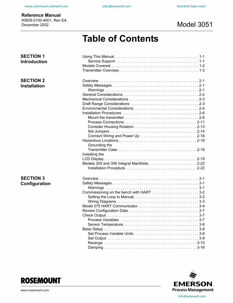
Figure 2-7. Low Power Transmitter Electronics Boards
2-16
NOTESecurity jumper not installed = Not Write ProtectedAlarm jumper not installed = High AlarmVoltage output jumper not installed = 1–5 V
VOLTAGE OUTPUT JUMPER POSITIONS
TRANSMITTER SECURITY JUMPER POSITIONS
0.8–3.2 V dc
1–5 V dc
Write Protect ON
Write Protect OFF
3051-3
031B
05D
Alarm
Connect Wiring and Power Up
NOTEUse shielded twisted pairs to yield best results. In order to ensure proper communication, use 24 AWG or larger wire, and do not exceed 5000 feet(1 500 meters). Installed signal wiring should not be run together and should not be in the same cable tray as AC power wiring.
The transmitter terminal block is in the compartment of the electronics housing labeled “FIELD TERMINALS.” The other compartment contains the transmitter electronics module. Connections for the HART-based communicator are attached beneath the terminal screws on the terminal block. You can connect the Rosemount Model 282 Loop Validator at the signal terminals to provide power to the transmitter temporarily for calibration or diagnostic purposes. Or you can attach it to the test connections on the terminal block of the transmitter for indication purposes. Figure 2-8 shows power supply load limitations for the transmitter.
om
Reference Manual 00809-0100-4001, Rev EA
December 2002 Model 3051
www.rosemount.aotewell.com [email protected] AoteWell Sales team
To make connections, perform the following procedure:
1. Remove the housing cover on the side marked “FIELD TERMINALS.” Do not remove the cover in explosive atmospheres when the circuit is live. All power to the transmitter is supplied over the signal wiring.
2. Connect the lead that originates at the positive side of the power supply to the terminal marked “+” and the lead that originates from the negative side of the power supply to the terminal marked “–”. Avoid contact with the leads and terminals. Do not connect the powered signal wiring to the test terminals. Power could damage the test diode in the test connection.
3. Plug and seal unused conduit connections on the transmitter housing to avoid moisture accumulation in the terminal side of the housing. If you do not seal the unused connections, mount the transmitter with the electrical housing positioned downward for drainage. Install wiring with a drip loop. Arrange the drip loop so the bottom is lower than the conduit connections and the transmitter housing.
Inductive-based transient protectors, including the Rosemount Model 470, can adversely affect the output of Model 3051 4–20 mA transmitters. Do not use the Model 470 for transient protection with the Model 3051. If your application requires transient protection, install the Transient Protection Terminal Block (Section 5: Troubleshooting).
Signal Wiring Grounding
Do not run signal wiring in conduit or open trays with power wiring, or near heavy electrical equipment. You may ground the signal wiring at any one point on the signal loop, or leave it ungrounded. The negative terminal of the power supply is a recommended grounding point. Device must be properly grounded or earthed according to local electric codes.
Power Supply for 4–20 mA Transmitters
The dc power supply should provide power with less than 2 percent ripple. The total resistance load is the sum of the resistance of the signal leads and the load resistance of the controller, indicator, and related pieces. Note that the resistance of intrinsic safety barriers, if used, must be included. See “Power Supply Effect” on page A-5 for additional power supply information.
NOTEA minimum loop resistance of 250 ohms is required to communicate with a HART Communicator. If a single power supply is used to power more than one Model 3051 transmitter, the power supply used, and circuitry common to the transmitters, should not have more than 20 ohms of impedance at 1200 Hz.
See “Safety Messages” on page 2-1 for complete warning information.
2-17

Reference Manual00809-0100-4001, Rev EA
December 2002Model 3051
2-18
www.rosemount.aotewell.com [email protected] AoteWell Sales team
Power supply for low power transmitters
Low-power transmitters require a 6–12 V dc external power supply.
Figure 2-8. Power Supply Load Limitations, 4–20 mA Transmitters
Voltage (V dc)
Communication requires a minimum loop resistance of 250 ohms.
Max. Loop Resistance = 43.5 (Power Supply Voltage – 10.5)
Operating Region
(1) For CSA approval, power supply must not exceed 42.4 V.
Lo
ad
(O
hm
s)
3051-0
103A
HAZARDOUS LOCATIONS
The Model 3051 has an Explosion-Proof housing and circuitry suitable for intrinsically safe and non-incendive operation. Individual transmitters are clearly marked with a tag indicating the certifications they carry. See Appendix B: Product Certifications for specific approval categories and installation drawings.
IMPORTANT NOTEOnce a device labeled with multiple approval types is installed, it should not be reinstalled using any other approval types. Permanently mark the approval label to distinguish it from unused approval types.
Grounding theTransmitter Case
The transmitter case should always be grounded in accordance with national and local electrical codes. The most effective transmitter case grounding method is direct connection to earth ground with minimal impedance. Methods for grounding the transmitter case include:
• Internal Ground Connection: The Internal Ground Connection screw is inside the FIELD TERMINALS side of the electronics housing. This screw is identified by a ground symbol ( ), and is standard on all Model 3051 transmitters.
• External Ground Assembly: This assembly is included with the optional transient protection terminal block (Option Code T1), and it is included with CESI/CENELEC Flame-Proof Certification (Option Code E8), BASEEFA/CENELEC Intrinsic Safety Certification (Option Code I1), and BASEEFA Type N Certification (Option Code N1). The External Ground Assembly can also be ordered with the transmitter (Option Code V5), or as a spare part (03031-0398-0001).
om
Reference Manual 00809-0100-4001, Rev EA
December 2002 Model 3051
www.rosemount.aotewell.com [email protected] AoteWell Sales team
NOTEGrounding the transmitter case using the threaded conduit connection may not provide a sufficient ground. The transient protection terminal block (Option Code T1) does not provide transient protection unless the transmitter case is properly grounded. Use the above guidelines to ground the transmitter case. Do not run the transient protection ground wire with signal wiring as the ground wire may carry excessive current if a lightning strike occurs.
INSTALLING THELCD DISPLAY
Figure 2-9. Optional LCD Display
For transmitters ordered with the LCD display, the display is shipped installed. Installing the display on an existing Model 3051 transmitter requires a small instrument screwdriver and the display kit.
The kits vary depending on the version of transmitter electronics. Examine the following numbers carefully to ensure you are installing the correct kit.
For Use with Shrouded Electronics Board
Meter Kits
Option M5: P/N 03031-0193-0101 (Aluminum housing)
Option M6: P/N 03031-0193-0111 (SST housing)
For Use with Non-Shrouded Electronics Board
Meter Kits
Option M5: P/N 03031-0193-0001
Option M6: P/N 03031-0193-0011
Interconnecting Pins
Jumpers (Top and Bottom)
LCD Display
Extended Cover
3051
-A05
E
info
@aotewell.c2-19
om

Reference Manual00809-0100-4001, Rev EA
December 2002Model 3051
2-20
www.rosemount.aotewell.com [email protected] AoteWell Sales team
The meter kit includes:
• one LCD display assembly
• one extended cover with O-ring installed
• two nylon standoffs
• two captive screws
• one ten-pin interconnection header
Use the following procedure and Figure 2-9 to install the LCD display. If the display is an upgrade from a previous version, upgrade the electronics board before attempting to install the display.
1. IF the transmitter is installed in a loop, THEN secure the loop and disconnect power.
2. Remove the transmitter cover opposite the field terminal side. Do not remove the instrument covers in explosive environments when the circuit is alive.
3. Remove the failure mode and alarm jumpers from the electronics module and insert them in their new positions above and below the display readout on the display assembly.
NOTEOn previous versions, remove only the alarm jumper.
4. Insert the interconnection header in the ten-pin socket exposed by removal of the jumpers. (Previous versions of the display use a six-pin connector.)
5. Remove the two captive screws from the electronics module. To do so, loosen the screws to release the module, then pull out the screws until they are stopped by the captive thread inside of the circuit board standoffs. Continue loosening the screws and remove them.
6. If necessary, rotate the electronics housing up to 180 degrees (left or right) to improve field access or to better view the LCD display. To rotate the housing:
a. Loosen the housing rotation set screw using a 9/64-in.hex wrench.
b. Turn the housing up to 180 degrees to the left or right of its original (as shipped) position. Do not rotate the housing more than 180 degrees without first performing a disassembly procedure (see “Disassembly Procedures” on page 5-3). Over-rotation will sever the electrical connection between the sensor module and the electronics module.
c. Retighten the housing rotation set screw.
See “Safety Messages” on page 2-1 for complete warning information.
Reference Manual 00809-0100-4001, Rev EA
December 2002 Model 3051
www.rosemount.aotewell.com [email protected] AoteWell Sales team
7. Decide which direction to orient the display. Insert the long display screws into the two holes on the display assembly that coincide with the holes on the electronics module. You can install the display in 90-degree increments for easy viewing. Position one of the four connectors on the back of the display assembly to accept the interconnection header.
8. Attach the display assembly to the electronics module by threading the screws into the captive threads and attaching the display assembly to the interconnection pins. Tighten the screws to secure the display assembly and electronics board in place.
9. Attach and tighten the extended cover. Transmitter covers must be fully engaged to meet Explosion-Proof requirements and to achieve the proper environmental seal.
Note the following LCD temperature limits:Operating: –4 to 175 °F (–20 to 80 °C)
Storage: –40 to 185 °F (–40 to 85 °C)
NOTEElectronics board revision 5.3.163 or later (all shrouded designs) are able to verify alarm current levels. After replacing the transmitter electronics board, sensor module, or LCD display, an alarm level test is recommended before returning the transmitter to service (see page 3-19).
See “Safety Messages” on page 2-1 for complete warning information.
2-21

Reference Manual00809-0100-4001, Rev EA
December 2002Model 3051
www.rosemount.aotewell.com [email protected] AoteWell Sales team
MODELS 305 AND 306 INTEGRAL MANIFOLDS
2-22
The Model 305 is available in two designs: Traditional and Coplanar. The traditional Model 305 Integral Manifold can be mounted to most primary elements with mounting adapters in the market today. The Model 306 Integral Manifold is used with In-line transmitters to provide block-and-bleed valve capabilities of up to 10000 psi (690 bar).
Figure 2-10. Integral Manifolds
COPLANAR DESIGN 3031A
29B
, D
06E
, 3051A
R
IN-LINE DESIGNTRADITIONAL DESIGN
Model 305 Integral Manifold Installation Procedure
To install a Model 305 Integral Manifold to a Model 3051 transmitter:
1. Inspect the Teflon sensor module O-rings. If the O-rings are undamaged, reusing them is recommended. If the O-rings are damaged (if they have nicks or cuts, for example), replace them with new O-rings.
IMPORTANTIf replacing the O-rings, take care not to scratch or deface the O-ring grooves or the surface of the isolating diaphragm while you remove the damaged O-rings.
2. Install the Integral Manifold on the sensor module. Use the four 2.25-in. manifold bolts for alignment. Finger tighten the bolts, then tighten the bolts incrementally in a cross pattern to final torque value. See “Mounting Bolts” on page 2-7 for complete bolt installation information and torque values. When fully tightened, the bolts should extend through the top of the module housing.
3. If the Teflon O-rings have been replaced, the flange bolts should be re-tightened after installation to compensate for cold flow of the O-rings.
NOTEAlways perform a zero trim on the transmitter/manifold assembly after installation to eliminate mounting effects.
Model 306 Integral Manifold Installation Procedure
The Model 306 Manifold is for use only with a Model 3051T transmitter.
Assemble the Model 306 Manifold to the Model 3051T transmitter with a thread sealant.
See “Safety Messages” on page 2-1 for complete warning information.

Reference Manual 00809-0100-4001, Rev EA
December 2002 Model 3051
www.rosemount.aotewell.com [email protected] AoteWell Sales team
Section 3 Configuration
www.rosemount.com
Commissioning on the bench with HART . . . . . . . . . . . . . . . page 3-2
Model 275 HART Communicator . . . . . . . . . . . . . . . . . . . . . page 3-4
Review Configuration Data . . . . . . . . . . . . . . . . . . . . . . . . . . page 3-7
Check Output . . . . . . . . . . . . . . . . . . . . . . . . . . . . . . . . . . . . page 3-7
Basic Setup . . . . . . . . . . . . . . . . . . . . . . . . . . . . . . . . . . . . . . page 3-8
LCD Display . . . . . . . . . . . . . . . . . . . . . . . . . . . . . . . . . . . . . page 3-16
Detailed Setup . . . . . . . . . . . . . . . . . . . . . . . . . . . . . . . . . . . page 3-19
Diagnostics and Service . . . . . . . . . . . . . . . . . . . . . . . . . . . . page 3-21
Advanced Functions . . . . . . . . . . . . . . . . . . . . . . . . . . . . . . . page 3-22
Multidrop Communication . . . . . . . . . . . . . . . . . . . . . . . . . . . page 3-25
OVERVIEW
This section contains information on commissioning and operating Model 3051 Smart Pressure Transmitters. Tasks that should be performed on the bench prior to installation are explained in this section.For your convenience, HART communicator fast key sequences are listed for each software function. If you are unfamiliar with the communicator or how to follow fast key sequences, please refer to your communicator manual for communicator operations.
SAFETY MESSAGES
Procedures and instructions in this section may require special precautions to ensure the safety of the personnel performing the operations. Information that raises potential safety issues is indicated by a warning symbol ( ). Refer to the following safety messages before performing an operation preceded by this symbol.Warnings
Explosions can result in death or serious injury.
• Do not remove the transmitter covers in explosive environments when the circuit is
live.
• Transmitter covers must be fully engaged to meet Explosion-Proof requirements.
• Before connecting a communicator in an explosive atmosphere, make sure the
instruments in the loop are installed in accordance with intrinsically safe or
nonincendive field wiring practices.

Reference Manual00809-0100-4001, Rev EA
December 2002Model 3051
3-2
www.rosemount.aotewell.com [email protected] AoteWell Sales team
Electrical shock can result in death or serious injury.
• Avoid contact with the leads and terminals. High voltage that may be present on
leads can cause electrical shock.
COMMISSIONING ON THE BENCH WITH HART
Commissioning consists of testing the transmitter and verifying transmitter configuration data. You may commission Model 3051 transmitters either before or after installation. Commissioning the transmitter on the bench before installation using a HART-based communicator or AMS ensures that all transmitter components are in good working order and acquaints you with the operation of the device.
To commission on the bench, connect the transmitter and the communicator as shown in Figure 3-1 and 3-2. Make sure the instruments in the loop are installed in accordance with intrinsically safe or nonincendive field wiring practices before connecting a communicator or AMS in an explosive atmosphere. Connect the communicator leads at any termination point in the signal loop. It is most convenient to connect them to the terminals labeled “COMM” on the terminal block. Connecting across the “TEST” terminals will prevent successful communication. To avoid exposing the transmitter electronics to the plant environment after installation, set all transmitter jumpers during the commissioning stage on the bench.
For 4–20 mA transmitters, you will need a power supply capable of providing 10.5 to 55 V dc at the transmitter, and a meter to measure output current. To enable communication, a resistance of at least 250 ohms must be present between the communicator or AMS loop connection and the power supply. Do not use inductive-based transient protectors with the Model 3051.
For more information on the Model 275 HART Communicator see document 00275-8026-0002. AMS help can be found in the AMS on-line guides within the AMS system.
Setting the Loop to Manual
Whenever you are preparing to send or request data that would disrupt the loop or change the output of the transmitter, you must set your process application loop to manual. Both the HART Communicator Model 275 and AMS will prompt you to set the loop to manual when necessary. Keep in mind that acknowledging this prompt does not set the loop to manual. The prompt is only a reminder; you have to set the loop to manual yourself as a separate operation.
See “Safety Messages” on page 3-1 for complete warning information.

Reference Manual 00809-0100-4001, Rev EA
December 2002 Model 3051
www.rosemount.aotewell.com [email protected] AoteWell Sales team
Wiring Diagrams
Bench Hook-upConnect the bench equipment as shown in Figure 3-1 and 3-2, and turn on the HART-based communicator by pressing the ON/OFF key. The communicator will search for a HART-compatible device and will indicate when the connection is made. If the communicator fails to connect, it will indicate that no device was found. If this occurs, refer to Troubleshooting page 5-1.
Field Hook-up
Figures 3-1 and 3-2 illustrate wiring loops for a field hook-up with a HART Communicator or AMS. Signal point may be grounded at any point or left ungrounded.
Figure 3-1. Wiring (4–20 mA)
24 V dc Supply
RL≥250Ω
Current Meter
3051-3
031G
02B
Figure 3-2. Wiring (Low-Power)
24 V dc Supply
Voltmeter
3051-3
031I0
2B
info
@aotewell.com3-3
Reference Manual00809-0100-4001, Rev EA
December 2002Model 3051
www.rosemount.aotewell.com [email protected] AoteWell Sales team
MODEL 275 HART COMMUNICATOR
3-4
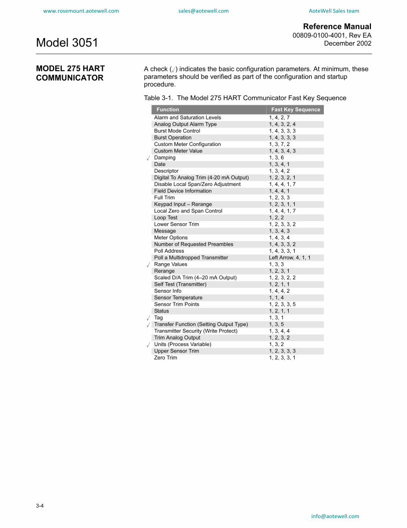
A check () indicates the basic configuration parameters. At minimum, these parameters should be verified as part of the configuration and startup procedure.
Table 3-1. The Model 275 HART Communicator Fast Key Sequence
Function Fast Key Sequence
Alarm and Saturation Levels 1, 4, 2, 7
Analog Output Alarm Type 1, 4, 3, 2, 4
Burst Mode Control 1, 4, 3, 3, 3
Burst Operation 1, 4, 3, 3, 3
Custom Meter Configuration 1, 3, 7, 2
Custom Meter Value 1, 4, 3, 4, 3
Damping 1, 3, 6
Date 1, 3, 4, 1
Descriptor 1, 3, 4, 2
Digital To Analog Trim (4-20 mA Output) 1, 2, 3, 2, 1
Disable Local Span/Zero Adjustment 1, 4, 4, 1, 7
Field Device Information 1, 4, 4, 1
Full Trim 1, 2, 3, 3
Keypad Input – Rerange 1, 2, 3, 1, 1
Local Zero and Span Control 1, 4, 4, 1, 7
Loop Test 1, 2, 2
Lower Sensor Trim 1, 2, 3, 3, 2
Message 1, 3, 4, 3
Meter Options 1, 4, 3, 4
Number of Requested Preambles 1, 4, 3, 3, 2
Poll Address 1, 4, 3, 3, 1
Poll a Multidropped Transmitter Left Arrow, 4, 1, 1
Range Values 1, 3, 3
Rerange 1, 2, 3, 1
Scaled D/A Trim (4–20 mA Output) 1, 2, 3, 2, 2
Self Test (Transmitter) 1, 2, 1, 1
Sensor Info 1, 4, 4, 2
Sensor Temperature 1, 1, 4
Sensor Trim Points 1, 2, 3, 3, 5
Status 1, 2, 1, 1
Tag 1, 3, 1
Transfer Function (Setting Output Type) 1, 3, 5
Transmitter Security (Write Protect) 1, 3, 4, 4
Trim Analog Output 1, 2, 3, 2
Units (Process Variable) 1, 3, 2
Upper Sensor Trim 1, 2, 3, 3, 3
Zero Trim 1, 2, 3, 3, 1

Reference Manual 00809-0100-4001, Rev EA
December 2002 Model 3051
www.rosemount.aotewell.com [email protected] AoteWell Sales team
Figure 3-3. HART Communicator menu tree for Model 3051
1 PROCESSOnline Menu
1 DEVICESETUP
2 PV
3 AO
4 LRV
5 URV
VARIABLE
2 DIAGNOSTICSAND SERVICE
3 BASIC SETUP
4 DETAILEDSETUP
5 Review
1 Pressure
2 Percent Range
3 Analog Output
4 SensorTemperature
1 TEST DEVICE
2 Loop Test
3 CALIBRATION
1 Self Test
2 Status
1 RERANGE
2 TRIM ANALOGOUTPUT
3 SENSOR TRIM
7 METER OPTS.
1 SENSORS
2 SIGNALCONDITION
3 OUTPUTCONDITION
4 DEVICEINFORMATION
4 RECALLFACTORY TRIM
1 Keypad Input
2 Apply Values
1 Digital-to-Analog Trim
2 Scaled D/A Trim
1 Zero Trim
2 Lower Sensor Trim
3 Upper Sensor Trim
4 Sensor Trim
Calibration Type
5 Sensor Trim Points
1 Keypad Input
2 Apply Values
1 Date
2 Descriptor
3 Message
4 Write Protect
1 Tag
2 Unit
3 RANGE VALUES
4 DEVICE INFO
5 Transfer Function
6 Damp
1 Meter Type
2 CUSTOMMETER SETUP
1 PRESSURESENSOR
2 TEMP SENSOR
1 Sensor Temp
2 Temperature Unit
1 Sel Dec Pt Pos
2 CM Upper Value
3 CM Lower Value
4 CM Units
5 CM xfer function
1 PROCESS VARIABLE
2 SENSOR SERVICE
3 Unit
1 Pressure
2 % Range
3 Sensor Temp
1 SENSORTRIM
2 Recall
Factory
Trim
1 Zero Trim
2 Lower SensorTrim
3 Upper SensorTrim
4 Sensor TrimCalibrationType
5 Sensor TrimPoints
1 PROCESSVARIABLE
2 RANGEVALUES
3 Unit
4 Transfer Func
5 Damp
6 Snsr Temp Unit
7 ALM/SATLEVELS
1 FIELD DEVICEINFO
2 SENSOR INFO
3 Self Test
4 DIAPHRAGMSEALS INFO
1 Pressure
2 % Range
3 Snsr Temp
1 Keypad Input
2 Apply Values1 High Alarm
2 Low Alarm
3 High Saturation
4 Low Saturation
5 AO Alarm Type
6 Alarm/Sat Type
1 Pressure
2 % Range
3 Analog Output
4 Sensor Temp
1 Loop Test
2 Digital-to-Analog Trim
3 Scaled D/A Trim
4 AO Alarm Type
1 Poll Address
2 Nos. of Req. Pream.
3 Burst Mode
4 Burst Option1 Meter Type
2 CUSTOM METERSETUP
3 Custom Meter Value
1 Measurement Type
2 Mod. Config. Type
3 Isolator Material
4 Fill Type
5 Proc. Conn. Type
6 Proc. Conn. Material
7 O-Ring Material
8 Drain/Vent Material
1 Sel. Dec. Pt. Pos.
2 CM Upper Value
3 CM Lower Value
4 CM Units
5 CM xfer function
1 Tag
2 Date
3 Descriptor
4 Message
5 Model
6 Write Protect
7 Local Keys
8 REVISION #S
9 Final Assy #
10 Device ID
11 Distributor
1 Univ.
Rev.
2 Fid. Dev.Rev.
3 S/W Rev.
1 # of Diaphr. Seals
2 Diaphr. Seal Type
3 Diaphr. Seal Fill
4 Diaphr. Material
NOTE“3051” will appear in the upper left of the communicator screen when this menu tree is valid.
1 Sensor Trim
2 Analog Output Trim
1 PROCESSVARIABLES
2 ANALOGOUTPUT
3 HART OUTPUT
4 METEROPTIONS
info@ao
tew3-5
ell.com

Reference Manual00809-0100-4001, Rev EA
December 2002Model 3051
www.rosemount.aotewell.com [email protected] AoteWell Sales team
Figure 3-4. HART Communicator menu tree for low power
Online Menu
1 DEVICE SETUP
2 PV
3 AO
4 LRV
5 URV
1 PROCESSVARIABLE
2 DIAGNOSTICSAND SERVICE
3 BASIC SETUP
4 DETAILEDSETUP
5 Review
1 Pressure
2 Percent Range
3 Analog Output
4 SensorTemperature
1 TEST DEVICE
2 Loop Test
3 CALIBRATION
1 Self Test
2 Status
1 RERANGE
2 TRIM ANALOGOUTPUT
3 SENSOR TRIM
1 SENSORS
2 SIGNALCONDITION
3 OUTPUTCONDITION
4 DEVICEINFORMATION
1 Keypad Input
2 Apply Values
1 Digital-to-Analog Trim
2 Scaled D/A Trim
1 Zero Trim
2 Lower Sensor Trim
3 Upper Sensor Trim
4 Sensor Trim Points
1 Keypad Input
2 Apply Values
1 Date
2 Descriptor
3 Message
4 Write Protect
5 Meter Type1 Tag
2 Unit
3 RANGE VALUES
4 DEVICE INFO
5 Transfer Function
6 Damp
1 PRESSURESENSOR
2 TEMP SENSOR
1 Sensor Temp2 Sensor Temp Unit
1 PROCESS VARIABLE
2 SENSOR SERVICE
3 Unit
1 Pressure2 % Range3 Sensor Temp
1 SENSORTRIM
1 Zero Trim2 Lower
Sensor Trim3 Upper
Sensor Trim4 Sensor Trim
Points
1 PROCESSVARIABLE
2 RANGEVALUES
3 Unit
4 Transfer Func
5 Damp
1 PROCESSVARIABLES
2 ANALOGOUTPUT
3 AO Alarm Type
4 HART OUTPUT
1 FIELD DEVICEINFO
2 SENSOR INFO
3 Meter Type
4 Self Test
1 Pressure2 % Range3 Snsr Temp
1 Keypad Input2 Apply Values
1 Pressure
2 % Range
3 Analog Output
4 Sensor Temp
1 Loop Test
2 Digital-to-Analog Trim
3 Scaled D/A Trim
4 AO Alarm Type
1 Poll Address
2 Nos. of Req. Pream.
3 Burst Mode
4 Burst Option
1 Measurement Type
2 Mod. Config. Type
3 Isolator Material
4 Fill Fluid
5 Flange Type
6 Proc. Conn. Material
7 Flange Material
8 Drain/Vent Material
9 # of Diaphr. Seals
Diaphr. Seal Type
Diaphr. Material
1 Tag
2 Date
3 Descriptor
4 Message
5 Model
6 Write Protect
7 Local Keys
8 REVISION #S
9 Final Assy #
Device ID
Distributor
1 Univ. Rev.
2 Fid. Dev. Rev.
3 S/W Rev.
3-6
info@a
otewell.com
Reference Manual 00809-0100-4001, Rev EA
December 2002 Model 3051
www.rosemount.aotewell.com [email protected] AoteWell Sales team
REVIEW CONFIGURATION DATAHART Comm 1, 5
NOTEInformation and procedures in this section that make use of HART Communicator fast key sequences assume that the transmitter and communicator are connected, powered, and operating correctly. If you are not familiar with the HART Communicator refer to the HART Communicator manual, document 00809-0100-4275
HART Communicator
Before you place the transmitter into operation, review the transmitter configuration data below which was set by the factory.
AMS
Right click on the device and select “Configuration Properties” from the menu. Select the tabs to review the transmitter configuration data.
Transmitter Model Type
Tag Range
Date Descriptor
Message Minimum and Maximum Sensor Limits
Minimum Span Units
4 and 20 mA points Output (linear or sq. root)
Damping Alarm Setting (high, low)
Security Setting (on, off) Local Zero/Span Keys (enabled, disabled)
Integral Display Sensor Fill
Isolator Material Flange (type, material)
O-Ring Material Drain/Vent
Remote Seal (type, fill fluid,
isolator material, number)
Transmitter S/N
Address Sensor S/N
CHECK OUTPUT
Before performing other transmitter on-line operations, review the digital output parameters to ensure that the transmitter is operating properly and is configured to the appropriate process variables.Process VariablesHART Comm. 1, 1
HART Communicator
The process variables for the Model 3051 provide the transmitter output, and are continuously updated. The process variable menu displays the following process variables:
• Pressure
• Percent of Range
• Analog Output
The pressure reading in both Engineering Units and Percent of Range will continue to track with pressures outside of the defined range from the lower to the upper range limit of the sensor module. (Previous versions of the software will track with pressure up to 105% of span and remain there as pressure increases.)
3-7

Reference Manual00809-0100-4001, Rev EA
December 2002Model 3051
3-8
www.rosemount.aotewell.com [email protected] AoteWell Sales team
NOTERegardless of the range points, the Model 3051 will measure and report all readings within the digital limits of the sensor. For example, if the 4 and 20 mA points are set to 0 and 10 inH2O, and the transmitter detects a pressure of 25 inH2O, it digitally outputs the 25 inH2O reading and a 250% of span reading. However, there may be up to ±5.0% error associated with output outside of the range points.
AMS
Right click on the device and select “Process Variables...” from the menu.The process variable screen displays the following process variables:
• Pressure
• Percent of range
• Analog output
• Sensor temperature
Sensor TemperatureHART Comm. 1, 1, 4
The Model 3051 contains a temperature sensor just above its pressure sensor in the sensor module. When reading this temperature, keep in mind that this is not a process temperature reading.
HART Communicator
Enter the fast key sequence below “Sensor Temperature” to view the sensor temperature reading.
AMS
Right click on the device and select “Process Variables...” from the menu. “Snsr Temp” is the sensor temperature reading.
BASIC SETUP
Set Process Variable UnitsHART Comm. 1, 3, 2
The PV Unit command sets the process variable units to allow you to monitor your process using the appropriate units of measure. Select from the following engineering units:
AMS
Right click on the device and select “Configuration Properties” from the menu. In the Basic Setup tab, use “Unit” drop down menu to select units.
• inH2O • bar
• inHg • mbar
• ftH2O • g/cm2
• mmH2O • kg/cm2
• mmHg • Pa
• psi • kPa
• torr • atm
• inH2O at 4 °C(1)
(1) Not available with low power or previous Model 3051 transmitters.
• mmH2O at 4 °C(1)

Reference Manual 00809-0100-4001, Rev EA
December 2002 Model 3051
www.rosemount.aotewell.com [email protected] AoteWell Sales team
Set OutputHART Comm. 1, 3, 5
Activate the transmitter square root output option to make the analog output proportional to flow. As the input approaches zero, the Model 3051 automatically switches to a linear output in order to ensure a more smooth, stable output near zero. See Figure 3-5.
The transition from linear to square root is not adjustable. It occurs at 0.8% of ranged pressure input or 9% of full-scale flow output in transmitters with Revision 5.2 or higher software. In earlier software, the transition point occurred at 4% of ranged pressure input, or 20% of full scale flow output.
From 0 percent to 0.6 percent of the ranged pressure input, the slope of the curve is unity (y = x). This allows accurate calibration near zero. Greater slopes would cause large changes in output for small changes at input. From 0.6 percent to 0.8 percent, the slope of the curve equals 42 (y = 42x) to achieve continuous transition from linear to square root at the transition point.
HART Communicator
Enter the fast key sequence below “Set Output (Transfer function).”
AMS
Right click on the device and select “Configuration Properties” from the menu.
1. In the Basic Setup tab, use “Xfer fnctn” drop down menu to select output, click Apply.
2. An “Apply Parameter Modifications” screen appears, enter desired information and click OK.
3. After carefully reading the warning provided, select OK.
Selecting Output Range for Low-Power Output Transmitters
Low power transmitters output either 1–5 V dc or 0.8–3.2 V dc depending on the position of the voltage output jumper. To reposition the voltage output jumper, follow the procedure described on page 2-14.
NOTEDefault low power output is 1–5 V dc. After changing output between 1–5 V and 0.8–3.2 V, perform a low power output trim.
3-9

Reference Manual00809-0100-4001, Rev EA
December 2002Model 3051
www.rosemount.aotewell.com [email protected] AoteWell Sales team
Figure 3-5. Square Root Output Transition Point
3-10
Sq. Root Curve
Transition Point
Linear Section
Slope=1
Slope=42
Transition Point
Sq. Root Curve
Full Scale Flow (%)
Full Scale Output(mA dc)
NOTEFor a flow turndown of less than 10:1 it is not recommended to perform a square root extraction in the transmitter. Instead, perform the square root extraction in the system.
Rerange
The Range Values command sets the 4 and 20 mA points (lower and upper range values). Setting the range values to the limits of expected readings maximizes transmitter performance. In practice, you may reset the transmitter range values as often as necessary to reflect changing process conditions.NOTERegardless of the range points, the Model 3051 will measure and report all readings within the digital limits of the sensor. For example, if the 4 and 20 mA points are set to 0 and 10 inH20, and the transmitter detects a pressure of 25 inH20, it digitally outputs the 25 inH20 reading and a 250% percent of span reading. However, there may be up to ±5.0% error associated with output outside of the range points.
Use one of three methods to rerange the transmitter. Each method is unique; examine all three closely before deciding which method to use.
Rerange with a Communicator Only
Reranging using only the communicator is the easiest and most popular way to rerange the transmitter. This method changes the values of the analog 4 and 20 mA points independently without a pressure input.
NOTEChanging the lower or upper range point results in similar changes to the span.
HART Comm. 1, 2, 3, 1, 1
info@aotewe
ll.com
Reference Manual 00809-0100-4001, Rev EA
December 2002 Model 3051
www.rosemount.aotewell.com [email protected] AoteWell Sales team
To rerange using only the communicator, enter the fast-key sequence above, select Keypad input, and follow the on-line instructions. Or enter the values directly from the HOME screen.
NOTEIf the transmitter security jumper is in the ON position, you will not be able to make adjustments to the zero and span. Refer to “Set Jumpers” on page 2-14 for the appropriate placement of the transmitter security jumper.
Rerange with a Pressure Input Source and a Communicator
Reranging using the communicator and a pressure source or process pressure is a way of reranging the transmitter when specific 4 and 20 mA points are not known. This method changes the values of the analog 4 and 20 mA points.
NOTEWhen you set the 4 mA point the span is maintained; when you set the 20 mA point the span changes. If you set the lower range point to a value that causes the upper range point to exceed the sensor limit, the upper range point is automatically set to the sensor limit, and the span is adjusted accordingly.
To rerange using the communicator and a pressure source or process pressure, enter the fast-key sequence above, select Apply values, and follow the on-line instructions.
NOTEIf the transmitter security jumper is in the ON position, you will not be able to make adjustments to the zero and span. Refer to “Set Jumpers” on page 2-14 for the appropriate placement of the transmitter security jumper.
Rerange with a Pressure Input Source and the Local Zero and
Span Buttons
Reranging using the local zero and span adjustments (see Figure 3-6 on page 3-12) and a pressure source is a way of reranging the transmitter when specific 4 and 20 mA points are not known and a communicator is not available.
NOTEWhen you set the 4 mA point the span is maintained; when you set the 20 mA point the span changes. If you set the lower range point to a value that causes the upper range point to exceed the sensor limit, the upper range point is automatically set to the sensor limit, and the span is adjusted accordingly.
HART Comm. 1, 2, 3, 1, 2
3-11

Reference Manual00809-0100-4001, Rev EA
December 2002Model 3051
3-12
www.rosemount.aotewell.com [email protected] AoteWell Sales team
To rerange the transmitter using the span and zero buttons, perform the following procedure:
1. Loosen the screw holding the certifications label on top of the transmitter housing, and rotate the label to expose the zero and span buttons (see Figure 3-6 on page 3-12).
2. Using a pressure source with an accuracy three to ten times the desired calibrated accuracy, apply a pressure equivalent to the lower range value to the high side of the transmitter.
3. To set the 4 mA point, press and hold the zero button for at least two seconds, then verify that the output is 4 mA. If a display is installed, it will display ZERO PASS.
NOTEThe zero and span adjustments on previous versions of the transmitter are screws instead of buttons. To activate the zero and span adjustments loosen the screws until they pop up.
4. Apply a pressure equivalent to the upper range value to the high side of the transmitter.
5. To set the 20 mA point, press and hold the span button for at least two seconds, then verify that the output is 20 mA. If a display is installed, it will display SPAN PASS.
NOTEIf the transmitter security jumper is in the ON position, or if the local zero and span adjustments are disabled through the software, you will not be able to make adjustments to the zero and span using the local buttons. Refer to “Set Jumpers” on page 2-14 for the proper placement of the transmitter security jumper. Or refer to “The Model 275 HART Communicator Fast Key Sequence” on page 3-4 for instructions on how to enable the span and zero buttons.
Figure 3-6. Local Zero andSpan Buttons
After you rerange the transmitter using the span and zero adjustments, it is possible to disable the adjustments to prevent further reranging.
Span and Zero Adjustment Buttons
3051-3031D02A
m
Reference Manual 00809-0100-4001, Rev EA
December 2002 Model 3051
www.rosemount.aotewell.com [email protected] AoteWell Sales team
Rerange with AMS only
Right click on the device and select “Configuration Properties” from the menu. In the Basic Setup tab, locate the Analog Output box and perform the following procedure:
1. Enter the lower range value (LRV) and the upper range value (URV) in the fields provided. Click Apply.
2. An “Apply Parameter Modifications” screen appears, enter desired information and click OK.
3. After carefully reading the warning provided, select OK.
Rerange with a Pressure Input Source and AMS
Right click on the device, select “Calibrate”, then “Apply values” from the menu.
1. Select Next after the control loop is set to manual.
2. From the “Apply Values” menu, follow the on-line instructions to configure lower and upper range values.
3. Select Exit to leave the “Apply Values” screen.
4. Select Next to acknowledge the loop can be returned to automatic control.
5. Select Finish to acknowledge the method is complete.
Model 3051C Differential/Gage Pressure Transmitter Range Limits
Range 1 Span Range 2 Span Range 3 Span Range 4 Span Range 5 Span
Units min max min max min max min max min max
inH2O 0.5 25 2.5 250 10 1000 83.040 8304 553.60 55360
inHg 0.03678 1.8389 0.18389 18.389 0.73559 73.559 6.1081 610.81 40.720 4072.04
ftH2O 0.04167 2.08333 0.20833 20.8333 0.83333 83.3333 6.9198 691.997 46.13 4613.31
mmH2O 12.7 635.5 63.553 6355 254 25421 2110.95 211095 14073 1407301
mmHg 0.93416 46.7082 4.67082 467.082 18.6833 1868.33 155.145 15514.5 1034.3 103430
psi 0.01806 0.903 0.0902 9.03183 0.36127 36.127 3 300 20 2000
bar 0.00125 0.06227 0.00623 0.62272 0.02491 2.491 0.20684 20.6843 1.37895 137.895
mbar 1.2454 62.2723 6.22723 622.723 24.9089 2490.89 206.843 20684.3 1378.95 137895
g/cm2 1.26775 63.3875 6.33875 633.875 25.355 2535.45 210.547 21054.7 1406.14 140614
kg/cm2 0.00127 0.0635 0.00635 0.635 0.0254 2.54 0.21092 21.0921 1.40614 140.614
Pa 124.545 6227.23 622.723 62160.6 2490.89 249089 20684.3 2068430 137895 13789500
kPa 0.12545 6.2272 0.62272 62.2723 2.49089 249.089 20.6843 2068.43 137.895 13789.5
torr 0.93416 46.7082 4.67082 467.082 18.6833 1868.33 155.145 15514.5 1034.3 103430
atm 0.00123 0.06146 0.00615 0.61460 0.02458 2.458 0.20414 20.4138 1.36092 136.092
NOTEWhen used with the HART Communicator Model 275 or the Rosemount Model 268 Communicator, ±5% adjustability is allowed on the sensor limit to allow for unit conversions.
3-13

Reference Manual00809-0100-4001, Rev EA
December 2002Model 3051
3-14
www.rosemount.aotewell.com [email protected] AoteWell Sales team
Model 3051P Differential/Gage Pressure Transmitter Range Limits
Range 2 Span Range 3 Span Range 4 Span Range 5 Span
Units min max min max min max min max
inH2O 25 250 100 1000 830.40 8304 5536.0 55360
inHg 1.8389 18.389 7.3559 73.559 61.081 610.81 407.20 4072.04
ftH2O 2.08333 20.8333 8.3333 83.3333 69.200 691.997 461.3 4613.31
mmH2O 635.5 6355 2542 25421 21109.5 211095 140730 1407301
mmHg 46.7082 467.082 186.833 1868.33 1551.45 15514.5 10343 103430
psi 0.903 9.03183 3.6127 36.127 30 300 200 2000
bar 0.06227 0.62272 0.2491 2.491 2.0684 20.6843 13.7895 137.895
mbar 62.2723 622.723 249.089 2490.89 2068.43 20684.3 13789.5 137895
g/cm2 63.3875 633.875 253.55 2535.45 2105.47 21054.7 14061.4 140614
kg/cm2 0.0635 0.635 0.254 2.54 2.1092 21.0921 14.0614 140.614
Pa 6216.06 62160.6 24908.9 249089 206843 2068430 1378950 13789500
kPa 6.2272 62.2723 24.9089 249.089 206.843 2068.43 1378.95 13789.5
torr 46.7082 467.082 186.833 1868.33 1551.45 15514.5 10343 103430
atm 0.06146 0.61460 0.2458 2.458 2.0414 20.4138 13.6092 136.092
NOTEWhen used with the HART Communicator Model 275 or the Rosemount Model 268 Communicator, ±5% adjustability is allowed on the sensor limit to allow for unit conversions.
Model 3051L/3051H Pressure Transmitter Range Limits
Range 2 Span Range 3 Span Range 4 Span Range 5 Span
Units min max min max min max min max
inH2O 2.5 250 10 1000 83.040 8304 553.60 55360
inHg 0.18389 18.389 0.73559 73.559 6.1081 610.81 40.720 4072.04
ftH2O 0.20833 20.8333 0.83333 83.3333 6.9198 691.997 46.13 4613.31
mmH2O 63.553 6355 254 25421 2110.95 211095 14073 1407301
mmHg 4.67082 467.082 18.6833 1868.33 155.145 15514.5 1034.3 103430
psi 0.0902 9.03183 0.36127 36.127 3 300 20 2000
bar 0.00623 0.62272 0.02491 2.491 0.20684 20.6843 1.37895 137.895
mbar 6.22723 622.723 24.9089 2490.89 206.843 20684.3 1378.95 137895
g/cm2 6.33875 633.875 25.355 2535.45 210.547 21054.7 1406.14 140614
kg/cm2 0.00635 0.635 0.0254 2.54 0.21092 21.0921 1.40614 140.614
Pa 622.723 62160.6 2490.89 249089 20684.3 2068430 137895 13789500
kPa 0.62272 62.2723 2.49089 249.089 20.6843 2068.43 137.895 13789.5
torr 4.67082 467.082 18.6833 1868.33 155.145 15514.5 1034.3 103430
atm 0.00615 0.61460 0.02458 2.458 0.20414 20.4138 1.36092 136.092
NOTEWhen used with the HART Communicator Model 275 or the Rosemount Model 268 Communicator, ±5% adjustability is allowed on the sensor limit to allow for unit conversions.

Reference Manual 00809-0100-4001, Rev EA
December 2002 Model 3051
www.rosemount.aotewell.com [email protected] AoteWell Sales team
Model 3051T Gage and Absolute Pressure Transmitter Range Limits
Range 1 Span Range 2 Span Range 3 Span Range 4 Span Range 5 Span
Units min max min max min max min max min max
inH2O 8.30397 831.889 41.5198 4159.45 221.439 22143.9 1107.2 110720 55360 276799
inHg 0.61081 61.0807 3.05403 305.403 16.2882 1628.82 81.441 8144.098 4072.04 20360.2
ftH2O 0.69199 69.3241 3.45998 345.998 18.4533 1845.33 92.2663 9226.63 4613.31 23066.6
mmH2O 211.10 21130 1054.60 105460.3 5634.66 563466 28146.1 2814613 1407301 7036507
mmHg 15.5145 1551.45 77.5723 7757.23 413.72 41372 2068.6 206860.0 103430 517151
psi 0.3 30 1.5 150 8 800 40 4000 2000 10000
bar 0.02068 3.06843 0.10342 10.3421 0.55158 55.1581 2.75791 275.7905 137.895 689.476
mbar 20.6843 2068.43 103.421 10342.11 551.581 55158.1 2757.91 275790.5 137895 689476
g/cm2 21.0921 2109.21 105.461 10546.1 561.459 56145.9 2807.31 280730.6 140614 703067
kg/cm2 0.02109 2.10921 0.10546 10.5461 0.56246 56.2456 2.81228 281.228 140.614 701.82
Pa 2068.43 206843 10342.1 1034212 55158.1 5515811 275791 27579054 13789500 68947600
kPa 2.06843 206.843 10.3421 1034.21 55.1581 5515.81 275.791 27579.05 13789.5 68947.6
torr 15.5145 1551.45 77.5726 7757.26 413.721 413721 2068.6 206859.7 103430 517151
atm 0.02041 2.04138 0.10207 10.2069 0.54437 54.4368 2.72184 272.1841 136.092 680.46
NOTEWhen used with the HART Communicator Model 275 or the Rosemount Model 268 Communicator, ±5% adjustability is allowed on the sensor limit to allow for unit conversions.
Model 3051T Gage and Absolute Pressure Transmitter Range Limits
Range 1 Span Range 2 Span Range 3 Span Range 4 Span Range 5 Span
Units min max min max min max min max min max
inH2O 4.62254 138.399 8.30397 831.889 41.5198 4151.98 221.439 22143.9 1107.2 110720
inHg 0.34002 10.1801 0.61081 61.0807 3.05403 305.403 16.2882 1628.82 81.441 8144.098
ftH2O 0.38521 11.5333 0.69199 69.3241 3.45998 345.998 18.4533 1845.33 92.2663 9226.63
mmH2O 117.510 3518.2 211.10 21130 6.35308 635.308 5634.66 563466 28146.1 2814613
mmHg 8.63642 258.575 15.5145 1551.45 1055.47 105547 413.72 41372 2068.6 206860.0
psi 0.16667 5 0.3 30 1.5 150 8 800 40 4000
bar 0.01151 0.344738 0.02068 2.06843 0.10342 10.342 0.55158 55.1581 2.75791 275.7905
mbar 11.5142 344.738 20.6843 2068.43 103.421 10342.1 551.581 55158.1 2757.91 275790.5
g/cm2 11.74 350.91 21.0921 2109.21 105.27 105.27 561.459 56145.9 2807.31 280730.6
kg/cm2 0.01174 0.351535 0.02109 2.10921 0.10546 10.546 0.56246 56.2456 2.81228 281.228
Pa 1151.42 34473.8 2068.43 206843 10342.1 1034210 55158.1 5515811 275791 27579054
kPa 1.15142 34.4738 2.06843 206.843 10.3421 1034.21 55.1581 5515.81 275.791 27579.05
torr 8.63642 258.575 15.5145 1551.45 77.5726 7757.26 413.721 413721 2068.6 206859.7
atm 0.01136 0.34023 0.02041 2.04138 0.10207 10.207 0.54437 54.4368 2.72184 272.1841
NOTEWhen used with the HART Communicator Model 275 or the Rosemount Model 268 Communicator, ±5% adjustability is allowed on the sensor limit to allow for unit conversions.
3-15

Reference Manual00809-0100-4001, Rev EA
December 2002Model 3051
www.rosemount.aotewell.com [email protected] AoteWell Sales team
DampingHART Comm. 1, 3, 6
3-16
The Damp command changes the response time of the transmitter to smooth variations in output readings caused by rapid changes in input. Determine the appropriate damping setting based on the necessary response time, signal stability, and other requirements of the of loop dynamics of your system. The default damping value is 0.4 seconds,(1) and can be reset to any of ten pre-configured damping values between 0 and 25.6 seconds.
AMS
Right click on the device and select “Configuration Properties” from the menu.
1. In the “Basic Setup” tab, enter the damping value in the “Damp” field, click Apply.
2. An “Apply Parameter Modifications” screen appears, enter desired information and click OK.
3. After carefully reading the warning provided, select OK.
LCD DISPLAYHART Comm. 1, 4, 3, 4
The Meter Options command allows you to customize the LCD display for use in your application. You can configure the display to display the following information:
• Engineering Units
• Percent of Range
• Custom Meter Display
• Alternating between Engineering Units and Percent of Range
• Alternating between Engineering Units and Custom Meter DisplayInstalled (Arrow down - Factory Default)
• None
• Unknown
• Spcl
NOTEThe user-configurable LCD scale is a feature specific to the current4–20 mA output transmitters. If you have a previous Model 3051 transmitter, upgrade the transmitter electronics board and LCD display to attain the current functionality.
(1) Model 3051CD0 default damping is 3.2 seconds. Model 3051CD1, with calibrations below
2.5 inH2O (0,62 kPa), have damping set at 3.2 seconds.

Reference Manual 00809-0100-4001, Rev EA
December 2002 Model 3051
www.rosemount.aotewell.com [email protected] AoteWell Sales team
Standard display Configuration
The factory default alternates between Engineering units and % Range (Factory default: INSTALLED = alt % Rnge/Eng units). To change the standard default, follow the following steps:
1. From the communicators main menu select (1) Device Setup (3) Basic Setup, (7) Meter Options.
2. Select (1) Meter Type. Using the up or down arrows scroll up or down until the desired display has been highlighted. Press ENTER (F4), SEND (F2), & HOME (F3).
NOTEUse the up and down arrow keys to scroll through the meter type selection shown above. (Installed, None, Unknown, and Spcl are the same as Alt % rnge/Eng). These options are only present do backward software compatibility.
AMS
Right click on the device and select “Configuration Properties” from the menu.
1. In the “Local Display” tab, locate the “Meter Type” area. Select the desired options to suit your application needs, click Apply.
2. An “Apply Parameter Modification” screen appears, enter desired information and click OK.
3. After carefully reading the warning provided, select OK.
Custom display Configuration
The user-configurable scale is a feature that enables the LCD display to display flow, level, or custom pressure units. With this feature you can define the decimal point position, the upper range value, the lower range value, the engineering units, and the transfer function.The display can be configured using a Model 275 HART Communicator (see Table A-1 on page 1-3) or AMS.
The user-configurable scale feature can define:
• decimal point position
• upper range values
• lower range values
• engineering units
• transfer function
3-17

Reference Manual00809-0100-4001, Rev EA
December 2002Model 3051
3-18
www.rosemount.aotewell.com [email protected] AoteWell Sales team
To configure the display using AMS, click the LOCAL DISPLAY tab on the CONFIGURATION PROPERTIES screen. To configure the display with a HART communicator, perform the following procedure:
1. Connect the communicator to the transmitter. Before connecting a communicator in an explosive atmosphere, make sure the instruments in the loop are installed according to intrinsically safe or nonincendive field wiring practices.
2. Change the Meter Type to “Custom Meter” by using the Fast Key sequence under “LCD Display” on page 3-16.
3. Next from the ONLINE screen, Select 1 Device Setup, 3 Basic Setup, 7 Meter Options, 2 Meter Options, 2 Custom Meter Setup
4. To specify decimal point position:
a. Select 1 Sel dec pt pos. Choose the decimal point representation that will provide the most accurate output for your application. For example, when outputting between 0 and 75 GPM, choose XX.XXX or use the decimal point examples below:
XXXXX
XXXX.X
XXX.XX
XX.XXX
X.XXXX
NOTE:Make sure the selection has been sent and the decimal point has changed before proceeding to the next step.
b. F2 SEND
5. To specify a custom upper range value:
a. Select 2 CM Upper Value. Type the value that you want the transmitter to read at the 20 mA point.
b. F2 SEND
6. To specify a custom lower range value:
a. Select 3 CM Lower Value. Type the value that you want the transmitter to read at the 4 mA point.
b. F2 SEND
7. To define custom units:
a. Select 4 CM Units. Enter the custom units (five characters maximum) that you want the display to display.
b. F2 SEND
8. To choose the transmitter transfer function for the display:
a. Select 5 CM xfer fnct. Enter the transmitter transfer function for the display. Select sq root to display flow units. The custom meter transfer function is independent of the analog output transfer function.
9. Select F2 SEND to upload the configuration to the transmitter.
See “Safety Messages” on page 3-1 for complete warning information.

Reference Manual 00809-0100-4001, Rev EA
December 2002 Model 3051
www.rosemount.aotewell.com [email protected] AoteWell Sales team
NOTE: You must change the meter type to custom meter display, see “LCD Display” on page 3-16. Follow the change standard display cofiguration steps and select custom meter display.
DETAILED SETUP
Failure Mode Alarm and Saturation
Model 3051 transmitters automatically and continuously perform self-diagnostic routines. If the self-diagnostic routines detect a failure, the transmitter drives its output outside of the normal saturation values. The transmitter will drive its output low or high based on the position of the failure mode alarm jumper. See Table 3-2, Table 3-3, and Table 3-4 for failure mode and saturation output levels. To select alarm position, see “Set Jumpers” on page 2-14.
Table 3-2. Standard Alarm and Saturation Values
Level
4–20 mA
Saturation
4–20 mA
Alarm
Low 3.9 mA ≤ 3.75 mA
High 20.8 mA ≥ 21.75 mA
Table 3-3. NAMUR-Compliant Alarm and Saturation Values
Level
4–20 mA
Saturation
4–20 mA
Alarm
Low 3.8 mA ≤ 3.6 mA
High 20.5 mA ≥ 22.5 mA
Table 3-4. Low-Power Alarm and Saturation Values
Level
1–5 V
Saturation
1–5 V
Alarm
0.8–3.2 V
Saturation
0.8–3.2 V
Alarm
Low 0.97 V ≤ 0.95 V 0.78 V ≤ 0.77 V
High 5.20 V ≥ 5.4 V 3.44 V ≥ 4.0 V
NOTEYou can alter the actual transmitter mA output values by performing an analog output trim.
NOTEWhen a transmitter is in an alarm condition, the hand-held HART communicator indicates the analog output the transmitter would drive if the alarm condition did not exist. The transmitter will alarm high in the event of failure if the alarm jumper is removed.
3-19

Reference Manual00809-0100-4001, Rev EA
December 2002Model 3051
www.rosemount.aotewell.com [email protected] AoteWell Sales team
Alarm and Saturation Levels for Burst Mode
3-20
Transmitters set to burst mode handle saturation and alarm conditions differently.
Alarm Conditions
• Analog output switches to alarm value.
• Primary variable (pressure) is burst with a status bit set.
• Percent of range follows primary variable (pressure).
• Temperature is burst with a status bit set.
Saturation
• Analog output switches to saturation value.
• Primary variable (pressure) is burst normally.
• Temperature is burst normally.
Alarm and Saturation Values for Multidrop Mode
Transmitters set to multidrop mode handle saturation and alarm conditions differently.
Alarm Conditions
• Primary variable (pressure) is sent with a status bit set.
• Percent of range follows primary variable (pressure).
• Temperature is sent with a status bit set.
Saturation
• Primary variable (pressure) is sent normally.
• Temperature is sent normally.
Alarm Level Verification
Transmitters with shrouded design electronics boards (board version 5.3 or later) have increased functionality that allows verification testing of alarm current levels. If you repair or replace the transmitter electronics board, sensor module, or LCD display, verify the transmitter alarm level before you return the transmitter to service. This feature is also useful in testing the reaction of your control system to a transmitter in an alarm state. To verify the transmitter alarm values, perform a loop test and set the transmitter output to the alarm value (see Tables 3-2, 3-3, and 3-4 on page 3-19, and “Loop Test” on page 3-21).Sensor Temperature Unit HART Comm. 1, 4, 1, 2, 2
The Sensor Temperature Output Unit Selection command selects between Celsius and Fahrenheit units for output of the sensor temperature. The sensor temperature output is accessible via HART only. (The Sensor Temperature Output Units command is not available on previous design transmitters or via AMS.)

Reference Manual 00809-0100-4001, Rev EA
December 2002 Model 3051
www.rosemount.aotewell.com [email protected] AoteWell Sales team
DIAGNOSTICS AND SERVICE
The diagnostics and service functions listed here are primarily for use after you install the transmitter in the field. The transmitter test feature is designed to verify that the transmitter is operating properly, and can be performed either on the bench or in the field. The loop test feature is designed to verify proper loop wiring and transmitter output, and should only be performed after you install the transmitter.
Transmitter TestHART Comm. 1, 2, 1, 1
The transmitter test command initiates a more extensive diagnostics routine than that performed continuously by the transmitter. The transmitter test routine can quickly identify potential electronics problems.
HART Communicator
If the transmitter test detects a problem, messages to indicate the source of the problem are displayed on the communicator screen.
AMS
Right click on the device and select “Diagnostics and Test,” then “Self test” from the menu.
1. Click Next to acknowledge test results.
2. Select Finish to acknowledge the method is complete.
Loop TestHART Comm. 1, 2, 2
The Loop Test command verifies the output of the transmitter, the integrity of the loop, and the operations of any recorders or similar devices installed in the loop. To initiate a loop test, perform the following procedure:
1. Connect a reference meter to the transmitter. To do so, either connect the meter to the test terminals on the transmitter terminal block, or shunt the power to the transmitter through the meter at some point in the loop.
2. From the HOME screen, select 1 Device Setup, 2 Diagnostics and Service, 2 Loop Test, to prepare to perform a loop test.
3. Select OK after you set the control loop to manual (see “Setting the Loop to Manual” on page 3-2). The communicator displays the loop test menu.
4. Select a discreet milliamp level for the transmitter to output. At the CHOOSE ANALOG OUTPUT prompt, select 1 4mA, 2 20mA, or select 3 other to manually input a value. IF you are performing a loop test to verify the output of a transmitter, THEN enter a value between 4 and 20 mA. IF you are performing a loop test to verify the transmitter alarm levels, THEN enter the milliamp value representing an alarm state (see Tables 3-2, 3-4, and 3-3 on page 3-19).
5. Check the electrical current meter installed in the test loop to verify that it reads the value you commanded the transmitter to output. IF the readings match, THEN the transmitter and the loop are configured and functioning properly. IF the readings do not match, THEN you may have the current meter attached to the wrong loop, there may be a fault in the wiring, the transmitter may require an output trim, or the electrical current meter may be malfunctioning.
After completing the test procedure, the display returns to the loop test screen and allows you to choose another output value or to exitloop testing.
3-21

Reference Manual00809-0100-4001, Rev EA
December 2002Model 3051
3-22
www.rosemount.aotewell.com [email protected] AoteWell Sales team
AMS
Right click on the device and select “Diagnostics and Test,” then “Loop test” from the menu.
1. Click Next after setting the control loop to manual.
2. Select desired analog output level. Click Next.
3. Click Next to acknowledge output being set to desired level.
4. Check the reference meter installed in the test loop to verify that it displays the commanded output value.
a. If the values match, the transmitter and the loop are configured and functioning properly.
b. If the values do not match, the current meter may be attached to the wrong loop there may be a fault in the wiring, the transmitter may require an output trim, or the reference meter may be malfunctioning.
After completing the test procedure, the display returns to the loop test screen to choose another output value or to end loop testing.
5. Select End and click Next to end loop testing.
6. Select Next to acknowledge the loop can be returned to automatic control.
7. Select Finish to acknowledge the method is complete.
ADVANCED FUNCTIONS
Saving, Recalling, and Cloning Configuration DataHART Comm. left arrow, 1, 2
Use the cloning feature of the Model 275 HART Communicator if you need to configure several Model 3051 transmitters similarly. The cloning process involves configuring a transmitter, saving the configuration data, then sending a copy of the data to a separate transmitter. There are a number of possible procedures to use when saving, recalling, and cloning configuration data. For complete instructions refer to the HART Communicator manual, publication no. 00809-0100-4275. One common method is as follows:
1. Completely configure the first transmitter.
2. Save the configuration data:
a. Select F2 SAVE from the communicator HOME/ONLINE screen.
b. Ensure that the location to which the data will be saved is set to MODULE. If it is not, select 1 Location to set the save location to MODULE.
c. Select 2 Name to name the configuration data. The default is the transmitter tag number.
d. Ensure that the data type is set to STANDARD. IF the data type is NOT STANDARD, THEN select 3 Data Type to set the data type to STANDARD.
e. Select F2 SAVE.
3. Connect and power the receiving transmitter and communicator.
4. Select the back arrow from the HOME/ONLINE screen. The HART Communicator menu appears.
5. Select 1 Offline, 2 Saved Configuration, 1 Module Contents to reach the MODULE CONTENTS menu.

Reference Manual 00809-0100-4001, Rev EA
December 2002 Model 3051
www.rosemount.aotewell.com [email protected] AoteWell Sales team
6. Use the DOWN ARROW to scroll through the list of configurations in the memory module, and use the RIGHT ARROW to select the configuration you wish to retrieve.
7. Select 1 Edit.
8. Select 1 Mark All.
9. Select F2 SAVE.
10. Use the DOWN ARROW to scroll through the list of configurations in the memory module, and use the RIGHT ARROW to select the configuration again.
11. Select 3 Send to download the configuration to the transmitter.
When finished, the communicator informs you of the status. To configure another transmitter, repeat Steps 3 through 10.
NOTEThe transmitter receiving the cloned data must have the same software version (or later) as the original transmitter.
AMS creating a Reusable Copy
To create a reusable copy of a configuration perform the following procedure:
1. Select View then User Configuration View from the menu bar (or click the toolbar button).
2. In the User Configuration window, right click and select New from the context menu.
3. In the New window, select a device from the list of templates shown, and click OK.
4. The template is copied into the User Configurations window, with the tag name highlighted; rename it as appropriate and press Enter.
NOTEA device icon can also be copied by dragging and dropping a device template or any other device icon from AMS Explorer or Device Connection View into the User Configurations window.
The “Compare Configurations” window appears, showing the Current values of the copied device on one side and mostly blank fields on the other (User Configuration) side.
5. Transfer values from the current configuration to the user configuration as appropriate or enter values by typing them into the available fields.
6. Click Apply to apply the values, or click OK to apply the values and close the window.
AMS Applying a User Configuration
Any amount of user configurations can be created for the application. They can also be saved, and applied to connected devices or to devices in the Device List or Plant Database.
3-23

Reference Manual00809-0100-4001, Rev EA
December 2002Model 3051
3-24
www.rosemount.aotewell.com [email protected] AoteWell Sales team
NOTEWhen using AMS Revision 6.0 or later, the device to which the user configuration is applied, bust be the same model type as the one created in the user configuration. When using AMS Revision 5.0 or earlier, the same model type and revision number are required.
To apply a user configuration perform the following procedure:
1. Select the desired user configuration in the User Configurations window.
2. Drag the icon onto a like device in AMS Explorer or Device Connection View. The Compare Configurations window opens, showing the parameters of the target device on one side and the parameters of the user configuration on the other.
3. Transfer parameters from the user configuration to the target device as desired, Click OK to apply the configuration and close the window.
Burst ModeHART Comm. 1, 4, 3, 3, 3
When configured for burst mode, the Model 3051 provides faster digital communication from the transmitter to the control system by eliminating the time required for the control system to request information from the transmitter. Burst mode is compatible with use of the analog signal. Because the HART protocol features simultaneous digital and analog data transmission, the analog value can drive other equipment in the loop while the control system is receiving the digital information. Burst mode applies only to the transmission of dynamic data (pressure and temperature in engineering units, pressure in percent of range, and/or analog output), and does not affect the way other transmitter data is accessed.
Access to information other than dynamic transmitter data is obtained through the normal poll/response method of HART communication. A HART-based communicator or the control system may request any of the information that is normally available while the transmitter is in burst mode. Between each message sent by the transmitter, a short pause allows the HART-based communicator or a control system to initiate a request. The transmitter will receive the request, process the response message, and then continue “bursting” the data approximately three times per second.
HART Communicator
To configure the transmitter for burst mode, perform the following step:
1. From the HOME screen, enter the fast key sequence below “Burst Mode.”
Reference Manual 00809-0100-4001, Rev EA
December 2002 Model 3051
www.rosemount.aotewell.com [email protected] AoteWell Sales team
AMS
Right click on the device and select “Configuration Properties” from the menu.
1. In the “HART” tab, use the drop down menu to select “Burst Mode ON or OFF.” For “Burst option” select the desired properties from the drop down menu. Burst options are as follows:
• PV
• % range/current
• Process vars/crnt
• Process variables
2. After selecting options click Apply.
3. An “Apply Parameter Modification” screen appears, enter desired information and click OK.
4. After carefully reading the warning provided, select OK.
MULTIDROP COMMUNICATION
Multidropping transmitters refers to the connection of several transmitters to a single communications transmission line. Communication between the host and the transmitters takes place digitally with the analog output of the transmitters deactivated. Many of the Rosemount SMART FAMILY® transmitters can be multidropped. With the HART smart communications protocol, up to 15 transmitters can be connected on a single twisted pair of wires or over leased phone lines. This feature can greatly reduce wiring costs.
The application of a multidrop installation requires consideration of the update rate necessary from each transmitter, the combination of transmitter models, and the length of the transmission line. Communication with the transmitters can be accomplished with commercially available Bell 202 modems and a host implementing the HART protocol. Each transmitter is identified by a unique address (1–15) and responds to the commands defined in the HART protocol. HART-based communicators can test, configure, and format a multidropped transmitter the same way as a transmitter in a standard point-to-point installation.
Figure 3-7 shows a typical multidrop network. This figure is not intended as an installation diagram. Contact Rosemount product support with specific requirements for multidrop applications.
NOTEA transmitter in multidrop mode has the analog output fixed at 4 mA. If a display is installed to a transmitter in multidrop mode, it will alternate the display between “current fixed” and the specified display output(s).
3-25

Reference Manual00809-0100-4001, Rev EA
December 2002Model 3051
www.rosemount.aotewell.com [email protected] AoteWell Sales team
Figure 3-7. Typical Multidrop Network
3-26
Power Supply
Bell 202 Modem
RS-232-C
NOTEMultidropping low-power transmitters requires special considerations. Consult factory for details.
3051-0
087A
, 3031A
07B
NOTEThe Model 3051 is set to address 0 at the factory, allowing it to operate in the standard point-to-point manner with a 4–20 mA output signal. To activate multidrop communication, the transmitter address must be changed to a number from 1 to 15. This change deactivates the4–20 mA analog output, sending it to 4 mA. It also disables the failure mode alarm signal, which is controlled by the upscale/downscale jumper position. Failure signals in multidropped transmitters are communicated through HART messages.
Changing a Transmitter AddressHART Comm. 1, 4, 3, 3, 1
To change the address of a multidropped transmitter, follow these fast key sequences. To activate multidrop communication, the transmitter address must be changed to a number from 1 to 15, and each transmitter in a multidropped loop must have a unique address.
HART Communicator
1. From the HOME screen, enter the fast key sequence below “Changing a Transmitter Address.”
AMS
Right click on the device and select “Configuration Properties” from the menu.
1. In the “HART” tab, in “ID” box, enter poll address located in the “Poll addr” box, click Apply.
2. An “Apply Parameter Modification” screen appears, enter desired information and click OK.
3. After carefully reading the warning provided, select OK.

Reference Manual 00809-0100-4001, Rev EA
December 2002 Model 3051
www.rosemount.aotewell.com [email protected] AoteWell Sales team
Communicating with a Multidropped TransmitterHART Comm. 1, 4, 3, 3, 2
HART Communicator
To communicate with a multidropped transmitter, configure the HART Communicator to poll for a non-zero address.
1. From the HOME screen, enter the fast key sequence below “Communicating with a Multidropped Transmitter.”
2. On the polling menu, scroll down and select “Digital Poll.” In this mode, the HART Communicator automatically polls for devices at addresses 0-15 upon start up.
AMS
Click on the HART modem icon and select “Scan All Devices.”
Polling a Multidropped TransmitterHART Comm. Left arrow, 4, 1
Polling a multidropped loop determines the model, address, and number of transmitters on the given loop.
HART Communicator
1. From the HOME screen, enter the fast key sequence below “Polling a Multidropped Transmitter.”
NOTEThe HART Communicator Model 275 requires you to use the UTILITY menu to perform and autopoll. This menu is available from the MAIN menu of the HART Communicator. Press the LEFT ARROW to move from the ONLINE MENU to the MAIN menu. Press 4 from the MAIN menu to access the UTILITY menu.
AMS
Click on the HART modem icon and select “Scan All Devices.”
3-27

Reference Manual00809-0100-4001, Rev EA
December 2002Model 3051
3-28
www.rosemount.aotewell.com [email protected] AoteWell Sales team

Reference Manual 00809-0100-4001, Rev EA
December 2002 Model 3051
www.rosemount.aotewell.com [email protected] AoteWell Sales team
Section 4 Operation and Maintenance
www.rosemount.com
Calibration . . . . . . . . . . . . . . . . . . . . . . . . . . . . . . . . . . . . . . page 4-2
Selecting Output Range for Low-Power . . . . . . . . . . . . . . page 4-20
Detailed Setup . . . . . . . . . . . . . . . . . . . . . . . . . . . . . . . . . . . page 4-20
OVERVIEW
SAFETY MESSAGES
Procedures and instructions in this section may require special precautions to ensure the safety of the personnel performing the operations. Information that raises potential safety issues is indicated by a warning symbol ( ). Refer to the following safety messages before performing an operation preceded by this symbol.Warnings
Explosions can result in death or serious injury.
• Do not remove the transmitter covers in explosive environments when the circuit is
live.
• Transmitter covers must be fully engaged to meet Explosion-Proof requirements.
• Before connecting a communicator in an explosive atmosphere, make sure the
instruments in the loop are installed in accordance with intrinsically safe or
nonincendive field wiring practices.
Electrical shock can result in death or serious injury.
• Avoid contact with the leads and terminals. High voltage that may be present on
leads can cause electrical shock.

Reference Manual00809-0100-4001, Rev EA
December 2002Model 3051
www.rosemount.aotewell.com [email protected] AoteWell Sales team
CALIBRATION
4-2
Calibrating a smart transmitter is different from calibrating an analog transmitter. The one-step calibration process of an analog transmitter is done in three steps with a smart transmitter:
• Rerange—sets the 4 and 20 mA points at the desired pressures;
• Sensor Trim—Adjusts the position of the factory characterization curve to optimize the transmitter performance over a specified pressure range or to adjust for mounting effects
• Analog Output Trim—Adjusts the analog output to match the plant standard or the control loop.
Smart transmitters operate differently than analog transmitters. A smart transmitter uses a microprocessor that contains information about the sensor’s specific characteristics in response to pressure and temperature inputs. A smart transmitter compensates for these sensor variations. The process of generating the sensor performance profile is called factory characterization. Factory characterization also provides the ability to readjust the 4 and 20 mA points without applying pressure to the transmitter.
The trim and rerange functions also differ. Reranging sets the transmitter analog output to the selected upper and lower range points and can be done with or without an applied pressure. Reranging does not change the factory characterization curve stored in the microprocessor. Sensor trimming requires an accurate pressure input and adds additional compensation that adjusts the position of the factory characterization curve to optimize transmitter performance over a specific pressure range.
NOTESensor trimming adjusts the position of the factory characterization curve. It is possible to degrade the performance of the transmitter if the sensor trim is done improperly or with inaccurate equipment. Contact your local Rosemount representative or call Rosemount Customer Central at 800-999-9307 if you have questions.
Table 4-1. RecommendedCalibration Tasks
Transmitter Bench Calibration Tasks Field Calibration Tasks
3051CD
3051CG
3051L
3051HD
3051HG
Set output configuration parameters:
• Set the range points.
• Set the output units.
• Set the output type.
• Set the damping value.
Optional, perform a full sensor trim.
(Accurate pressure source required.)
Optional, perform an analog output trim.
(Accurate multimeter required.)
Reconfigure parameters if necessary.
Zero trim the transmitter to compensate for mounting
effects or static pressure effects.
3051CA
3051TA
3051TG
Set output configuration parameters:
• Set the range points.
• Set the output units.
• Set the output type.
• Set the damping value.
Optional: Perform a full sensor trim if equipment available
(accurate absolute pressure source required), otherwise
perform the low trim value section of the full sensor trim
procedure.
Optional: Perform an analog output trim (multimeter required).
Reconfigure parameters if necessary.
Perform low trim value section of the full sensor trim
procedure to correct for mounting position effects.

Reference Manual 00809-0100-4001, Rev EA
December 2002 Model 3051
www.rosemount.aotewell.com [email protected] AoteWell Sales team
NOTE:A HART communicator is required for all sensor and output trim procedures.
Model 3051C Range 4 and Range 5 transmitters require a special calibration procedure when used in differential pressure applications under high static line pressure (see “Compensating for Line Pressure” on page 4-12).
Model 3051TG Range 5 transmitters use an absolute sensor that requires an accurate absolute pressure source to perform the optional full sensor trim.
Calibration Overview
Complete calibration of the Model 3051 Pressure Transmitter involves the following tasks:Configure the Analog Output Parameters
Set Process Variable Units (page 3-8)
Set Output Type (page 3-9)
Rerange (page 3-10)
Set Damping (page 3-16)
Calibrate the Sensor
Full Trim (page 4-8)
Zero Trim (page 4-7)
Calibrate the 4–20 mA Output
4–20 mA Output Trim (page 4-10) or
4–20 mA Output Trim Using Other Scale (page 4-11) or
Low-Power 1–5 V dc or Low-Power 0.8–3.2 V dc (page 4-10)
Figure 4-1 illustrates the Model 3051 transmitter data flow. This data flow can be summarized in four major steps:
1. A change in pressure is measured by a change in the sensor output (Sensor Signal).
2. The sensor signal is converted to a digital format that can be understood by the microprocessor (Analog-to-Digital Signal Conversion).
3. Corrections are performed in the microprocessor to obtain a digital representation of the process input (Digital PV).
4. The Digital PV is converted to an analog value (Digital-to-Analog Signal Conversion).
Figure 4-1 also identifies the approximate transmitter location for each calibration task. Note that the data flows from left to right, and a parameter change affects all values to the right of the changed parameter.
Not all calibration procedures should be performed for each Model 3051 transmitter. In addition, some procedures are appropriate for bench calibration but should not be performed during field calibration. Table 4-1 identifies the recommended calibration procedures for each type of Model 3051 transmitter for both bench and field calibration.
4-3

Reference Manual00809-0100-4001, Rev EA
December 2002Model 3051
www.rosemount.aotewell.com [email protected] AoteWell Sales team
Figure 4-1. Transmitter Data Flow with Calibration Options
4-4
Transmitter Electronics Module
Microprocessor Digital PV
Sensor
Input DeviceOutput Device
20.00 mA
3051: PT-4001
1 Device SetupOnline
2PV100.00 inH2O3AO20.00 mA4LRV0.00 inH2O5URV100.00 inH2O
Transmitter Ranged 0 to 100 inH2O
Input Pressure
Sensor Signal A
na
log
Ou
tpu
t
HA
RT
C
om
mu
nic
ato
r
NOTEValue on PV line should equal the input pressure. Value on AO line should equal the output device reading.
1151-1151F05B
Determining Calibration Frequency
Calibration frequency can vary greatly depending on the application, performance requirements, and process conditions. The following procedure can be used as a guideline to estimate the calibration frequency. Actual calibration frequency should follow plant standard and sound engineering practice.
1. Determine the performance required for your application.
2. Determine the operating conditions.
3. Calculate the Total Probable Error (TPE).
4. Calculate the stability per month.
5. Calculate the calibration frequency.
info@aotewe
ll.co m
Reference Manual 00809-0100-4001, Rev EA
December 2002 Model 3051
www.rosemount.aotewell.com [email protected] AoteWell Sales team
Figure 4-2. Calculating Calibration Frequency
Sample Calculation
Step 1: Determine the performance required for your application.
0.00
0.10
0.20
0.30
0.40
0.50
0.60
0.70
0.80
12 24 36 48 60
Months in Service
% o
f S
pa
n E
rro
r
Step 1: Required Performance = 0.30% of span
Step 2: Operating Conditions
Transmitter = Model 3051CD, Range 2 (URL = 250 inH2O)
Calibrated Span = 150 in H2O
Ambient Temperature Change =± 50 °F
Line Pressure = 500 psig
Step 3: Calculate TPE
Step 4: Calculate Stability
Step 5: Calculate Calibration Frequency
Required Performance: 0.30% of span
Step 2: Determine the operating conditions.
Transmitter: Model 3051CD, Range 2 (URL=250 inH2O)
Calibrated Span: 150 inH2O
Ambient Temperature Change: ± 50 °F
Line Pressure: 500 psig
Step 3: Calculate total probable error (TPE).· 2 2 2
TPE = = 0.117% of span
Where:
Reference Accuracy = ± 0.075% of span
Ambient Temperature Effect =
Span Static Pressure Effect(1) =
(1) Zero static pressure effect removed by zero trimming at line pressure, assume reading is 70% of span.
RefAccuracy( ) TempEffect( ) StaticPressureEffect( )+ +
0.0125 URL×Span
------------------------------------- 0.0625+ per 50 °F 0.0833% of span±=±
0.1% reading per 1000 psi = % of range * 0.1% * Cal. Span per 1000 psi =
0.035% of span for line pressure of 500 psig
Step 4: Calculate the stability per month.
Step 5: Calculate calibration frequency.
Stability0.125xURL( )
Span------------------------------------ % of span for 5 years 0.0035% of span per month±=±=
Cal. Freq.Req. Performance TPE–( )
Stability per Month-----------------------------------------------------------------------
0.3% 0.117%–( )0.0035%
--------------------------------------------- 52 months= = =
30
4-5
51-3051_20A

Reference Manual00809-0100-4001, Rev EA
December 2002Model 3051
www.rosemount.aotewell.com [email protected] AoteWell Sales team
Choosing a Trim Procedure
4-6
To decide which trim procedure to use, you must first determine whether the analog-to-digital section or the digital-to-analog section of the transmitter electronics is in need of calibration. To do so, refer to Figure 4-1 and perform the following procedure:
1. Connect a pressure source, a HART communicator, and a digital readout device to the transmitter.
2. Establish communication between the transmitter andthe communicator.
3. Apply pressure equal to the upper range point pressure (100 inH20, for example).
4. Compare the applied pressure to the Process Variable (PV) line on the Communicator On-line Menu. IF the PV reading on the communicator does not match the applied pressure, and you are confident that your test equipment is accurate, THEN perform a sensor trim.
5. Compare the Analog Output (AO) line on the communicator on-line menu to the digital readout device. IF the AO reading on the communicator does not match the digital readout device, and you are confident that your test equipment is accurate, THEN perform an output trim.
Sensor Trim
You can trim the sensor using either the full trim or the zero trim function. The trim functions vary in complexity, and their use is application-dependent. Both trim functions alter the transmitter’s interpretation of the input signal.Zero trim is a single-point adjustment. It is useful for compensating for mounting position effects and is most effective when performed with the transmitter installed in its final mounting position. Since this correction maintains the slope of the characterization curve, it should not be used in place of a full trim over the full sensor range.
When performing a zero trim, ensure that the equalizing valve is open and all wet legs are filled to the correct levels.
NOTEDo not perform a zero trim on Model 3051 Absolute pressure transmitters. A zero trim is zero based, and absolute pressure transmitters reference absolute zero. To correct mounting position effects on a Model 3051 Absolute Pressure Transmitter, perform a low trim within the full sensor trim function. The low trim function provides a “zero” correction similar to the zero trim function but it does not require the input to be zero based.
A full trim is a two-point sensor calibration where two end-point pressures are applied, and all output is linearized between them. You should always adjust the low trim value first to establish the correct offset. Adjustment of the high trim value provides a slope correction to the characterization curve based on the low trim value. The factory-established characterization curve is not changed by this procedure. The trim values allow you to optimize performance over your specified measuring range at the calibration temperature.
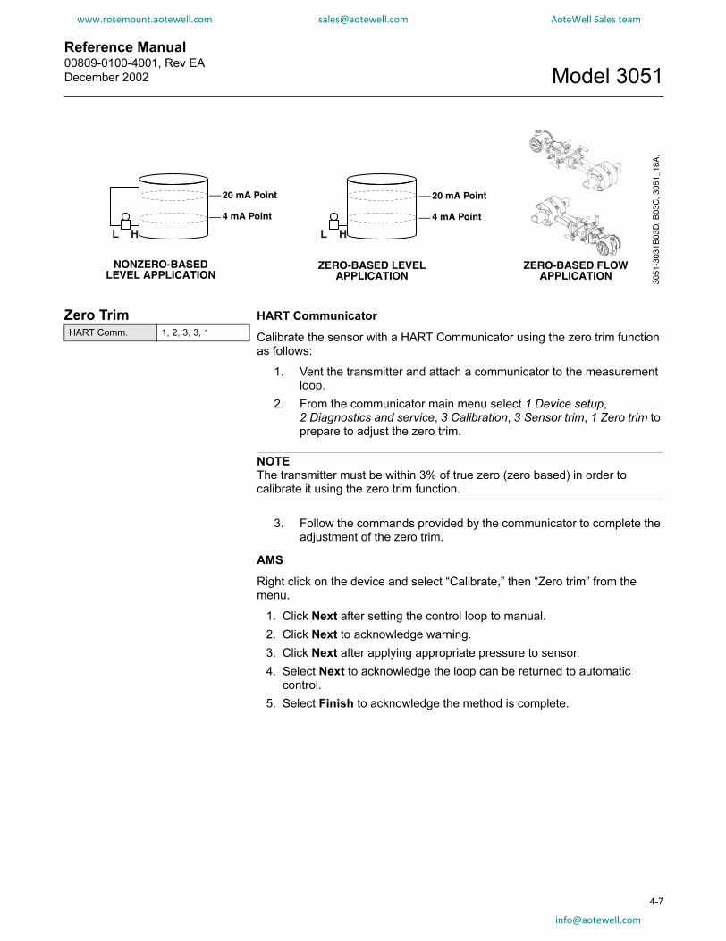
Reference Manual 00809-0100-4001, Rev EA
December 2002 Model 3051
www.rosemount.aotewell.com [email protected] AoteWell Sales team
ZERO-BASED FLOW APPLICATION
ZERO-BASED LEVEL APPLICATION
NONZERO-BASED LEVEL APPLICATION
3051
-303
1B03
D, B
03C
, 305
1_18
A,
20 mA Point
4 mA Point
20 mA Point
4 mA Point
Zero TrimHART Comm. 1, 2, 3, 3, 1
HART Communicator
Calibrate the sensor with a HART Communicator using the zero trim function as follows:
1. Vent the transmitter and attach a communicator to the measurement loop.
2. From the communicator main menu select 1 Device setup, 2 Diagnostics and service, 3 Calibration, 3 Sensor trim, 1 Zero trim to prepare to adjust the zero trim.
NOTEThe transmitter must be within 3% of true zero (zero based) in order to calibrate it using the zero trim function.
3. Follow the commands provided by the communicator to complete the adjustment of the zero trim.
AMS
Right click on the device and select “Calibrate,” then “Zero trim” from the menu.
1. Click Next after setting the control loop to manual.
2. Click Next to acknowledge warning.
3. Click Next after applying appropriate pressure to sensor.
4. Select Next to acknowledge the loop can be returned to automatic control.
5. Select Finish to acknowledge the method is complete.
4-7

Reference Manual00809-0100-4001, Rev EA
December 2002Model 3051
www.rosemount.aotewell.com [email protected] AoteWell Sales team
Full TrimHART Comm. 1, 2, 3, 3
4-8
NOTEUse a pressure input source that is at least three times more accurate than the transmitter, and allow the input pressure to stabilize for ten seconds before entering any values.
HART Communicator
To calibrate the sensor with a HART Communicator using the full trim function, perform the following procedure:
1. Assemble and power the entire calibration system including a transmitter, HART Communicator, power supply, pressure input source, and readout device.
2. From the HOME screen, enter the fast key sequence below under “Full Trim.”
3. Select 2: Lower sensor trim
NOTESelect pressure input values so that low and high values are equal to or outside the 4 and 20 mA points. Do not attempt to obtain reverse output by reversing the high and low points. The transmitter allows approximately five percent URL deviation from the characterized curve established at the factory.
4. Follow the commands provided by the HART Communicator to complete the adjustment of the lower value.
5. Repeat the procedure for the upper value, replacing 2: Lower sensor trim with 3: Upper sensor trim in Step 3.
AMS
Right click on the device and select “Calibrate,” then “Sensor trim” from the menu.
1. Select “Lower sensor trim.”
2. Click Next after setting the control loop to manual.
3. Click Next after applying appropriate pressure to sensor.
4. Select Next to acknowledge the loop can be returned to automatic control.
5. Select Finish to acknowledge the method is complete.
6. Right click on the device and select “Calibrate,” select “Sensor trim” from the menu.
7. Select “Upper sensor trim” and repeat steps 2-5.

Reference Manual 00809-0100-4001, Rev EA
December 2002 Model 3051
www.rosemount.aotewell.com [email protected] AoteWell Sales team
Figure 4-3. Digital Trim Connection Drawing(4–20 mA Transmitters)
Dead Weight TesterCalibration Standardfor Sensor Trim Only
HART-BasedCommunicator
24 V dc Power Supply
250 Ω Minimum Loop Resistance
Model 3051 Transmitter
Precision Meter
3051-3031A01B
Recall Factory Trim
The Recall Factory Trim commands allow the restoration of the as-shipped factory settings of the sensor trim and analog output trim.NOTEThe Recall Factory Trim commands are not available on previousdesign transmitters.
Recall Factory Trim — Sensor Trim
Resets the transmitter sensor trim to the as-shipped factory settings. The Recall Factory Trim—Sensor Trim command can be useful for recovering from an inadvertent zero trim of an absolute pressure unit.
HART Communicator
Enter the fast key sequence below “Recall Factory Trim — Sensor Trim” to reset the transmitter sensor trim.
Recall Factory Trim — Analog Output
Resets the transmitter analog output trim to the as-shippedfactory settings. The Recall Factory Trim—Analog Output command can be useful for recovering from an inadvertent zero trim on an absolute pressure transmitter.
HART Communicator
Enter the fast key sequence below “Recall Factory Trim — Analog Output” to reset the analog output trim.
HART Comm. 1, 2, 3, 4, 1
HART Comm. 1, 2, 3, 4, 2
4-9

Reference Manual00809-0100-4001, Rev EA
December 2002Model 3051
www.rosemount.aotewell.com [email protected] AoteWell Sales team
Analog Output Trim
4-10
The Analog Output Trim commands allow you to adjust the transmitter’s current output at the 4 and 20 mA points to match the plant standards. This command adjusts the digital to analog signal conversion (see Figure 4-1 on page 4-4).
Analog Output Trim (Low Power)
The Model 3051 Low-Power Transmitter has two jumper-selectable output ranges: 1–5 V dc and 0.8–3.2 V dc. Positioning this jumper for the desired output range selects the proper coefficients for temperature corrections. The jumper position also sets the output values(1–5 or 0.8–3.2) which are communicated through HART protocol and accessed by a hand held communicator.
However, switching this jumper does not by itself select the new outputs; you must perform the “Digital-to-Analog Trim” procedure above to match the transmitter’s output voltages to the newjumper selection.
HART Comm. 1, 2, 3, 2, 1
Digital-to-Analog TrimHART Comm. 1, 2, 3, 2, 1
HART Communicator
To perform a digital-to-analog trim with a HART communicator, perform the following procedure.
1. From the HOME screen, select 1 Device setup, 2 Diag/Service, 3 Calibration, 2 D/A trim. Select OK after you set the control loop to manual (see “Setting the Loop to Manual” on page 3-2).
2. Connect an accurate reference ammeter to the transmitter at the CONNECT REFERENCE METER prompt. To do so, connect the positive lead to the positive terminal and the negative lead to the test terminal in the transmitter terminal compartment, or shunt the transmitter power through the reference meter at some point.
3. Select OK after connecting the reference meter.
4. Select OK at the SETTING FLD DEV OUTPUT TO 4 MA prompt. The transmitter outputs 4,00 mA.
5. Record the actual value from the reference meter, and enter it at the ENTER METER VALUE prompt. The communicator prompts you to verify whether or not the output value equals the value on the reference meter.
6. Select 1 Yes if the reference meter value equals the transmitter output value, or 2 No if it does not.IF you select 1 Yes, THEN proceed to Step 7.IF you select 2 No, THEN repeat Step 5.
7. Select OK at the SETTING FLD DEV OUTPUT TO 20 MA prompt, and repeat Steps 5 and 6 until the reference meter value equals the transmitter output value.
8. Select OK after you return the control loop to automatic control.

Reference Manual 00809-0100-4001, Rev EA
December 2002 Model 3051
www.rosemount.aotewell.com [email protected] AoteWell Sales team
AMS
Right click on the device and select “Calibrate,” then “D/A Trim” from the menu.
1. Click Next after setting the control loop to manual.
2. Click Next after connecting the reference meter.
3. Click Next at the “Setting fld dev output to 4mA” screen.
4. Record the actual value from the reference meter, and enter it at the “Enter meter value” screen and click Next.
5. Select Yes, if the reference meter value equals the transmitter output value, or No if it does not. Click Next.
a. If Yes is selected, proceed to Step 6.
b. If No is selected, repeat Step 4.
6. Click Next at the “Setting fld dev output to 20mA” screen.
7. Repeat Step 4 - Step 5 until the reference meter equals the transmitter output value.
8. Select Next to acknowledge the loop can be returned to automatic control.
9. Select Finish to acknowledge the method is complete.
Digital-to-Analog Trim Using Other ScaleHART Comm. 1, 2, 3, 2, 2
The Scaled D/A Trim command matches the 4 and 20 mA points to a user-selectable reference scale other than 4 and 20 mA (1 to 5 volts if measuring across a 250 ohm load, or 0 to 100 percent if measuring from a DCS, for example). To perform a scaled D/A trim, connect an accurate reference meter to the transmitter and trim the output signal to scale as outlined in the Output Trim procedure.
NOTEUse a precision resistor for optimum accuracy. If you add a resistor to the loop, ensure that the power supply is sufficient to power the transmitter to a 20 mA output with the additional loop resistance.
4-11

Reference Manual00809-0100-4001, Rev EA
December 2002Model 3051
4-12
www.rosemount.aotewell.com [email protected] AoteWell Sales team
AMS
Right click on the device and select “Calibrate,” then “Scaled D/A trim” from the menu.
1. Click Next after setting the control loop to manual.
2. Select Change to change scale, click Next.
3. Enter Set scale-Lo output value, click Next.
4. Enter Set scale-Hi output value, click Next.
5. Click Next to proceed with Trim.
6. Click Next after connecting the reference meter.
7. Click Next at the “Setting fld dev output to 4 mA” screen.
8. Record the actual value from the reference meter, and enter it at the “Enter meter value” screen and click Next.
9. Select Yes, if the reference meter value equals the transmitter output value, or No if it does not. Click Next.
a. If Yes is selected, proceed to Step 10.
b. If No is selected, repeat Step 8.
10. Click Next at the “Setting fld dev output to 20mA” screen.
11. Repeat Step 8 - Step 9 until the reference meter equals the transmitter output value.
12. Select Next to acknowledge the loop can be returned to automatic control.
13. Select Finish to acknowledge the method is complete.
Compensating for Line Pressure
Range 4 and 5 Differential Transmitters
Model 3051 Range 4 and Range 5 pressure transmitters require a special calibration procedure when used in differential pressure applications. The purpose of this procedure is to optimize transmitter performance by reducing the effect of static line pressure in these applications. Model 3051 differential pressure transmitters (Ranges 1, 2, and 3) do not require this procedure because the optimization occurs in the sensor.
Applying high static pressure to Model 3051 Range 4 and Range 5 pressure transmitters causes a systematic shift in the output. This shift is linear with static pressure; correct it by performing the Full Trim procedure on page 2-18.
The following specifications show the static pressure effect for Model 3051 Range 4 and Range 5 transmitters used in differential pressure applications:
Zero Effect:
±0.1% of the upper range limit per 1000 psi (6,9 MPa) for line pressures from 0 to 2000 psi (0 to 13,8 MPa)
±0.2% of the upper range limit per 1000 psi (6,9 MPa) for line pressures above 2000 psi (13,8 MPa)
Span Effect:
Correctable to ±0.2% of reading per 1000 psi for line pressures from 0 to 3626 psi.

Reference Manual 00809-0100-4001, Rev EA
December 2002 Model 3051
www.rosemount.aotewell.com [email protected] AoteWell Sales team
The systematic span shift caused by the application of static line pressure is –1.00% of reading per 1000 psi for 3051C Range 4 transmitters, and –1.25% of reading per 1000 psi for Range 5 transmitters.
Use the following example to compute corrected input values.
Example
A transmitter with model number 3051CD4 will be used in a differential pressure application where the static line pressure is 1200 psi. The transmitter is ranged so that the output is 4 mA at 500 inH2O and 20 mA at 1500 inH2O.
To correct for systematic error caused by high static line pressure, first use the following formulas to determine corrected values for the low trim and high trim.
LT = LRV + S (LRV) P
Where: LT = Corrected Low Trim Value
LRV = Lower Range Value
S = –(Span shift per specification)
P = Static Line Pressure
HT = URV + S (URV) P
Where: HT = Corrected High Trim ValueURV = Upper Range Value
S = –(Span shift per specification)
P = Static Line Pressure
In this example:
URV = 1500 inH2O
LRV = 500 inH2O
P = 1200 psi
S = ± 0.01/1000
To calculate the low trim (LT) value:
LT = 500 + (0.01/1000)(500)(1200)
LT = 506 inH2O
To calculate the high trim (HT) value:
HT = 1500 + (0.01/1000)(1500)(1200)
HT = 1518 inH2O
To complete a Model 3051 full trim and enter the corrected values for low trim (LT) and high trim (HT), refer to “Full Trim” on page 4-8.
Enter the corrected input values for low trim and high trim through the communicator keypad after you apply the nominal value of pressure as the transmitter input.
4-13

Reference Manual00809-0100-4001, Rev EA
December 2002Model 3051
4-14
www.rosemount.aotewell.com [email protected] AoteWell Sales team
NOTEAfter calibrating Model 3051 Range 4 and Range 5 transmitters for high differential pressure applications, rerange the 4 and 20 mA points using the communicator to maintain the systematic static line pressure correction. You may re-zero the 4 mA point at line pressure after installation using the local zero button without affecting the completed calibration.
Diagnostic Messages
In addition to the output, the LCD meter displays abbreviated operation, error, and warning messages for troubleshooting the transmitter. Messages appear according to their priority, with normal operating messages appearing last. To determine the cause of a message, use a Model 275 HART Communicator to further interrogate the transmitter. A description of each LCD diagnostic message follows.Error
Error messages appear on the LCD meter display to inform you of serious problems effecting the operation of the transmitter. The meter displays an error message until the error condition is corrected, and the analog output is driven to the specified alarm level. No other transmitter information is displayed during an alarm condition.
FAIL(1)
The transmitter CPU board and the sensor module are incompatible. If you encounter this message, contact Rosemount Customer Central at 800-999-9307 if you need assistance.
Fail Module
The sensor module is disconnected or is malfunctioning. Verify that the sensor module ribbon cable is connected to the back of the electronics board. If the ribbon cable is properly connected, there is a problem within the sensor module. Possible sources of problems include:
• Pressure or temperature updates are not being received in the sensor module.
• A non-volatile memory fault that will effect transmitteroperation has been detected in the module by the memory verification routine.
Some non-volatile memory faults are user-repairable. Use a Model 275 HART Communicator to diagnose the error and determine if it is repairable. Any error message that ends in “FACTORY” is not repairable. In cases of non user-repairable errors, you must replace the sensor module. See “Disassembly Procedures” on page 5-3 or contact Rosemount Customer Central at 800-999-9307 if you need assistance.
(1) For previous versions of the meter, FAIL MODULE and FAIL ELECT were also grouped into
the FAIL message. When dealing with a FAIL message on a previous version meter, review
the information in the FAIL MODULE and FAIL ELECT sections as well.

Reference Manual 00809-0100-4001, Rev EA
December 2002 Model 3051
www.rosemount.aotewell.com [email protected] AoteWell Sales team
Fail Elect
The transmitter electronics board is malfunctioning due to an internal fault. Some of the FAIL ELECT errors are user-repairable. Use a Model 275 HART Communicator to diagnose the error and determine if it is repairable. Any error message that ends in “FACTORY” is not repairable. In cases of non user-repairable errors, you must replace the electronics board. See “Disassembly Procedures” on page 5-3 or contact Rosemount Customer Central at 800-999-9307 if youneed assistance.
Fail Config
A memory fault has been detected in a location that could effect transmitter operation, and is user-accessible. To correct this problem, use a Model 275 HART Communicator to interrogate and reconfigure the appropriate portion of the transmitter memory. Contact Rosemount Customer Central at 800-999-9307 if you need assistance.
Warnings
Warnings appear on the LCD display to alert you of user-repairable problems with the transmitter, or current transmitter operations. Warnings appear alternately with other transmitter information until the warning condition is corrected or the transmitter completes the operation that warrants the warning message.
NOTEThe warning messages on previous versions of the LCD display may vary slightly from those listed here, but they represent the same warning.
Press Limit
The process variable read by the transmitter is outside of the transmitter’s range.
Temp Limit
The secondary temperature variable read by the transmitter is outside of the transmitter’s range.
Curr Fixed
The transmitter is in multidrop mode. The analog output is not tracking pressure changes.
Curr Saturd
The pressure read by the module is outside of the specified range, and the analog output has been driven to saturation levels.
Loop Test
A loop test is in progress. During a loop test or 4–20 mA trim, the analog output is set to a fixed value. The meter display alternates between the current selected in milliamps and “LOOP TEST.”
4-15
Reference Manual00809-0100-4001, Rev EA
December 2002Model 3051
4-16
www.rosemount.aotewell.com [email protected] AoteWell Sales team
Xmtr Info
A non-volatile memory fault has been detected in the transmitter memory by the memory verification routine. The memory fault is in a location containing transmitter information. To correct this problem, use a Model 275 HART Communicator to interrogate and reconfigure the appropriate portion of the transmitter memory. This warning does not effect the transmitter operation. Contact Rosemount Customer Central at 800-999-9307 if you need assistance.
Operation
Normal operation messages appear on the LCD meter to confirm actions or inform you of transmitter status. Operation messages are displayed with other transmitter information, and warrant no action to correct or alter the transmitter settings.
Zero Pass
The zero value, set with the local zero adjustment button, has been accepted by the transmitter, and the output should change to 4 mA.
Zero Fail
The zero value, set with the local zero adjustment button, exceeds the maximum rangedown allowed for a particular range, or the pressure sensed by the transmitter exceeds the sensor limits.
Span Pass
The span value, set with the local span adjustment button, has been accepted by the transmitter, and the output should change to 20 mA.
Span Fail
The span value, set with the local span adjustment button, exceeds the maximum rangedown allowed for a particular range, or the pressure sensed by the transmitter exceeds the sensor limits.
LOCAL DSBLD
This message appears during reranging with the integral zero and span buttons and indicates that the transmitter local zero and span adjustments have been disabled. The adjustments may have been disabled by the transmitter security jumper on the transmitter circuit board or through software commands from the Model 275. See “Security (Write Protect)” on page 2-14 for information on the position of the security jumper and information on software lockout.
Write Protect
This message appears if you attempt to change the transmitter configuration data while the security jumper is in the ON position. See “Security (Write Protect)” on page 2-14 for more information about the security jumper.
HART Communicator Diagnostics
The following table is a list of messages used by the HART Communicator (HC) and their corresponding descriptions.
Variable parameters within the text of a message are indicated with<variable parameter>.
Reference to the name of another message is identified by [another message].

Reference Manual 00809-0100-4001, Rev EA
December 2002 Model 3051
www.rosemount.aotewell.com [email protected] AoteWell Sales team
Message Description
1k snsr EEPROM
error-factory ON
Replace the sensor module
1k snsr EEPROM
error-user-no out ON
Use the HART communicator to reset the following
parameters: remote seal isolator, remote seal fill fluid,
flange material, o-ring material, transmitter type, remote
seal type, flange type, meter type, number of remote
seals.
1k snsr EEPROM
error-user ON
Perform a full trim to recalibrate the transmitter.
4k micro EEPROM
error-factory ON
Replace the electronics board.
4k micro EEPROM
error-user-no out ON
Use the hart communicator to reset the message field.
4k micro EEPROM
error-user ON
Use the HART communicator to reset the following
parameters: units, range values, damping, analog output,
transfer function, tag, scaled meter values. Perform a d/a
trim to ensure that the error is corrected.
4k snsr EEPROM
error-factory ON
Replace the sensor module.
4k snsr EEPROM
error-user ON
Use the HART communicator to reset the temperature
units and the calibration type.
Add item for ALL device types
or only for this ONE device type.
Asks the user whether the hot key item being added
should be added for all device types or only for the type of
device that is connected.
Command Not Implemented The connected device does not support this function.
Communication Error The communicator and the device are not communicating
correctly. Check all connections between the
communicator and the device and resend the information.
Configuration memory not
compatible with connected
device
The configuration stored in memory is incompatible with
the device to which a transfer has been requested.
CPU board not initialized ON The electronics board is not initialized.
Replace the electronics board.
CPU EEPROM write failure ON Message sent to electronics board from HART signal
failed. Replace the electronics board.
Device Busy The connected device is busy performing another task.
Device Disconnected The device failed to respond to a command. Check all
connections between the communicator and the device
and resend the command.
Device write protected Device is in write-protect mode. Data can not be written.
Device write protected. Do you
still want to
shut off?
Device is in write-protect mode. Press YES to turn the
HART communicator off and lose the unsent data.
Display value of variable on
hotkey menu?
Asks whether the value of the variable should be
displayed adjacent to its label on the hotkey menu if the
item being added to the hotkey menu is a variable.
Download data from
configuration memory to device
Press the SEND softkey to transfer information from the
communicator memory to the device.
Exceed field width Indicates that the field width for the current arithmetic
variable exceeds the device-specified description edit
format.
Exceed precision Indicates that the precision for the current arithmetic
variable exceeds the device-specified description edit
format.
Ignore next 50 occurrences of
status?
Select YES to ignore the next 50 occurrences of device
status, or select no to display every occurrence.
Illegal character An invalid character for the variable type was entered.
Illegal date The day portion of the date is invalid.
4-17

Reference Manual00809-0100-4001, Rev EA
December 2002Model 3051
4-18
www.rosemount.aotewell.com [email protected] AoteWell Sales team
Illegal month The month portion of the date is invalid.
Illegal year The year portion of the date is invalid.
Incompatible CPU board and
module ON
Upgrade the electronics board or the sensor module to
the
current revision.
Incomplete exponent The exponent of a scientific notation floating point
variable
is incomplete.
Incomplete field The value entered is not complete for the variable type.
Looking for a device Polling for multidropped devices at addresses 1–15.
Local buttons operator error ON Illegal pressure applied during zero or span operation.
Repeat the process after verifying the correct pressures.
Mark as read only variable on
hotkey menu?
Asks whether the user should be allowed to edit the
variable from the hotkey menu if the item being added to
the hotkey menu is a variable.
Module EEPROM write failure
ON
Message sent to the module from the HART signal failed.
Replace the sensor module.
No device configuration in
configuration memory
There is no configuration saved in memory available to
re-configure off-line or transfer to a device.
No Device Found Poll of address zero fails to find a device, or poll of all
addresses fails to find a device if auto-poll is enabled.
No hotkey menu available for
this device.
There is no menu named “hotkey” defined in the device
description for this device.
No pressure updates ON No pressure updates being received from the sensor
module. Verify that the sensor module ribbon cable is
attached correctly. Or replace the sensor module.
No offline devices available. There are no device descriptions available to be used to
configure a device offline.
No simulation devices available. There are no device descriptions available to simulate a
device.
No temperature updates ON No temperature updates being received from the sensor
module. Verify that the sensor module ribbon cable is
attached correctly. Or replace the sensor module.
No UPLOAD_VARIABLES in ddl
for this device
There is no menu named “upload_variables” defined in
the device description for this device. This menu is
required for offline configuration.
No Valid Items The selected menu or edit display contains no valid items.
OFF KEY DISABLED Appears when the user attempts to turn the HC off before
sending modified data or before completing a method.
Online device disconnected
with unsent data. RETRY or OK
to lose data.
There is unsent data for a previously connected device.
Press RETRY to send data, or press OK to disconnect
and lose unsent data.
Out of memory for hotkey
configuration. Delete
unnecessary items.
There is no more memory available to store additional
hotkey items. Unnecessary items should be deleted to
make space available.
Overwrite existing configuration
memory
Requests permission to overwrite existing configuration
either by a device-to-memory transfer or by an offline
configuration. User answers using the softkeys.
Press OK... Press the OK softkey. This message usually appears after
an error message from the application or as a result of
HART communications.
Restore device value? The edited value that was sent to a device was not
properly implemented. Restoring the device value returns
the variable to its original value.
ROM checksum error ON Checksum of transmitter software has detected a fault.
Replace the electronics board.
Save data from device to
configuration memory
Prompts user to press SAVE softkey to initiate a
device-to-memory transfer.
Message Description

Reference Manual 00809-0100-4001, Rev EA
December 2002 Model 3051
www.rosemount.aotewell.com [email protected] AoteWell Sales team
Saving data to configuration
memory.
Data is being transferred from a device to configuration
memory.
Sending data to device. Data is being transferred from configuration memory to a
device.
Sensor board not initialized ON The sensor module electronics board is not initialized.
Replace the sensor module.
There are write only variables
which have not been edited.
Please edit them.
There are write-only variables which have not been set by
the user. These variables should be set or invalid values
may be sent to the device.
There is unsent data. Send it
before shutting off?
Press YES to send unsent data and turn the HC off. Press
NO to turn the HC off and lose the unsent data.
Too few data bytes received Command returns fewer data bytes than expected as
determined by the device description.
Transmitter Fault Device returns a command response indicating a fault
with the connected device.
Units for <variable label> has
changed. Unit must be sent
before editing, or invalid data
will be sent.
The engineering units for this variable have been edited.
Send engineering units to the device before editing this
variable.
Unsent data to online device.
SEND or LOSE data
There is unsent data for a previously connected device
which must be sent or thrown away before connecting to
another device.
Upgrade 275 software to access
XMTR function.
Continue with old description?
The communicator does not contain the most recent
Model 3051 Device Descriptors (DDs). Select YES to
communicate using the existing DDs. Select NO to abort
communication.
Use up/down arrows to change
contrast. Press DONE when
done.
Gives direction to change the contrast of the HC display.
Value out of range The user-entered value is either not within the range for
the given type and size of variable or not within the
min/max specified by the device.
<message> occurred
reading/writing <variable label>
Either a read/write command indicates too few data bytes
received, transmitter fault, invalid response code, invalid
response command, invalid reply data field, or failed pre-
or post-read method; or a response code of any class
other than SUCCESS is returned reading a particular
variable.
<variable label> has an
unknown value. Unit must be
sent before editing, or invalid
data will be sent.
A variable related to this variable has been edited. Send
related variable to the device before editing this variable.
Message Description
Local Zero and Span (Local Keys) Software Lock Out
To enable this feature, see “Local Span and Zero Control (Local Keys)” on page 4-20.
Physical Removal of Local Zero and Span (Local Keys)
To remove the magnetic buttons used to activate the local zero and span, use a small slotted head screwdriver and pry off the small, plastic cap located under the approval tag. Remove button assemblies and discard.
NOTEOn previous versions of Model 3051, remove the magnetic screws.
NOTEAlarm jumper not installed = High Alarm
4-19
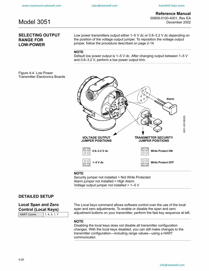
Reference Manual00809-0100-4001, Rev EA
December 2002Model 3051
www.rosemount.aotewell.com [email protected] AoteWell Sales team
SELECTING OUTPUT RANGE FOR LOW-POWER
4-20
Low power transmitters output either 1–5 V dc or 0.8–3.2 V dc depending on the position of the voltage output jumper. To reposition the voltage output jumper, follow the procedure described on page 2-14.
NOTEDefault low power output is 1–5 V dc. After changing output between 1–5 V and 0.8–3.2 V, perform a low power output trim.
Figure 4-4. Low Power Transmitter Electronics Boards
NOTESecurity jumper not installed = Not Write ProtectedAlarm jumper not installed = High AlarmVoltage output jumper not installed = 1–5 V
VOLTAGE OUTPUT
JUMPER POSITIONS
TRANSMITTER SECURITY
JUMPER POSITIONS
0.8–3.2 V dc
1–5 V dc
Write Protect ON
Write Protect OFF
3051-3
031B
05D
Alarm
DETAILED SETUP
Local Span and Zero Control (Local Keys)HART Comm. 1, 4, 4, 1, 7
The Local keys command allows software control over the use of the local span and zero adjustments. To enable or disable the span and zero adjustment buttons on your transmitter, perform the fast key sequence at left.
NOTEDisabling the local keys does not disable all transmitter configuration changes. With the local keys disabled, you can still make changes to the transmitter configuration—including range values—using a HART communicator.
om
Reference Manual 00809-0100-4001, Rev EA
December 2002 Model 3051
www.rosemount.aotewell.com [email protected] AoteWell Sales team
Section 5 Troubleshooting
www.rosemount.com
Before Disassembling the Transmitter . . . . . . . . . . . . . . . page 5-3
Disassembly Procedures . . . . . . . . . . . . . . . . . . . . . . . . . . page 5-3
Reassembly Procedures . . . . . . . . . . . . . . . . . . . . . . . . . . page 5-5
OVERVIEW
Table 5-1 provides summarized troubleshooting suggestions for the most common operating problems.If you suspect a malfunction despite the absence of any diagnostic messages on the communicator display, follow the procedures described here to verify that transmitter hardware and process connections are in good working order. Always deal with the most likely and easiest-to-check conditions first.
SAFETY MESSAGES
Procedures and instructions in this section may require special precautions to ensure the safety of the personnel performing the operations. Information that raises potential safety issues is indicated by a warning symbol ( ). Refer to the following safety messages before performing an operation preceded by this symbol.Warnings
Explosions can result in death or serious injury.
• Do not remove the transmitter covers in explosive environments when the
circuit is live.
• Both transmitter covers must be fully engaged to meet Explosion-Proof
requirements.
• Before connecting a communicator in an explosive atmosphere, make sure
that the instruments in the loop are installed according to intrinsically safe or
nonincendive field wiring practices.
Static electricity can damage sensitive components.
• Observe safe handling precautions for static-sensitive components.

Reference Manual00809-0100-4001, Rev EA
December 2002Model 3051
www.rosemount.aotewell.com [email protected] AoteWell Sales team
Table 5-1. Model 3051Stroubleshooting table
5-2
Symptom Corrective Actions
Transmitter milliamp reading is zero Verify power is applied to signal terminals
Check power wires for reversed polarity
Verify terminal voltage is 10.5 to 42.4 V dc
Check for open diode across test terminal
Transmitter Not Communicating with
HART Communicator
Verify the output is between 4 and 20 mA or saturation levels
Verify clean DC Power to transmitter (Max AC noise 0.2 volts peak to peak)
Check loop resistance, 250 Ω minimum (PS voltage -transmitter voltage/loop current)
Check if unit is addressed properly
Transmitter milliamp reading is low or high Verify applied pressure
Verify 4 and 20 mA range points
Verify output is not in alarm condition
Verify if 4 – 20 mA output trim is required
Transmitter will not respond to changes in
applied pressure
Check test equipment
Check impulse piping or manifold for blockage
Verify applied pressure is between the 4 and 20 mA set points
Verify output is not in alarm condition
Verify transmitter is not in Loop Test mode
Digital Pressure Variable reading is low or high Check test equipment (verify accuracy)
Check impulse piping for blockage or low fill in wet leg
Verify transmitter is calibrated properly
Verify pressure calculations for application
Digital Pressure Variable reading is erratic Check application for faulty equipment in pressure line
Verify transmitter is not reacting directly to equipment turning on/off
Verify damping is set properly for application
Milliamp reading is erratic Verify power source to transmitter has adequate voltage and current
Check for external electrical interference
Verify transmitter is properly grounded
Verify shield for twisted pair is only grounded at one end
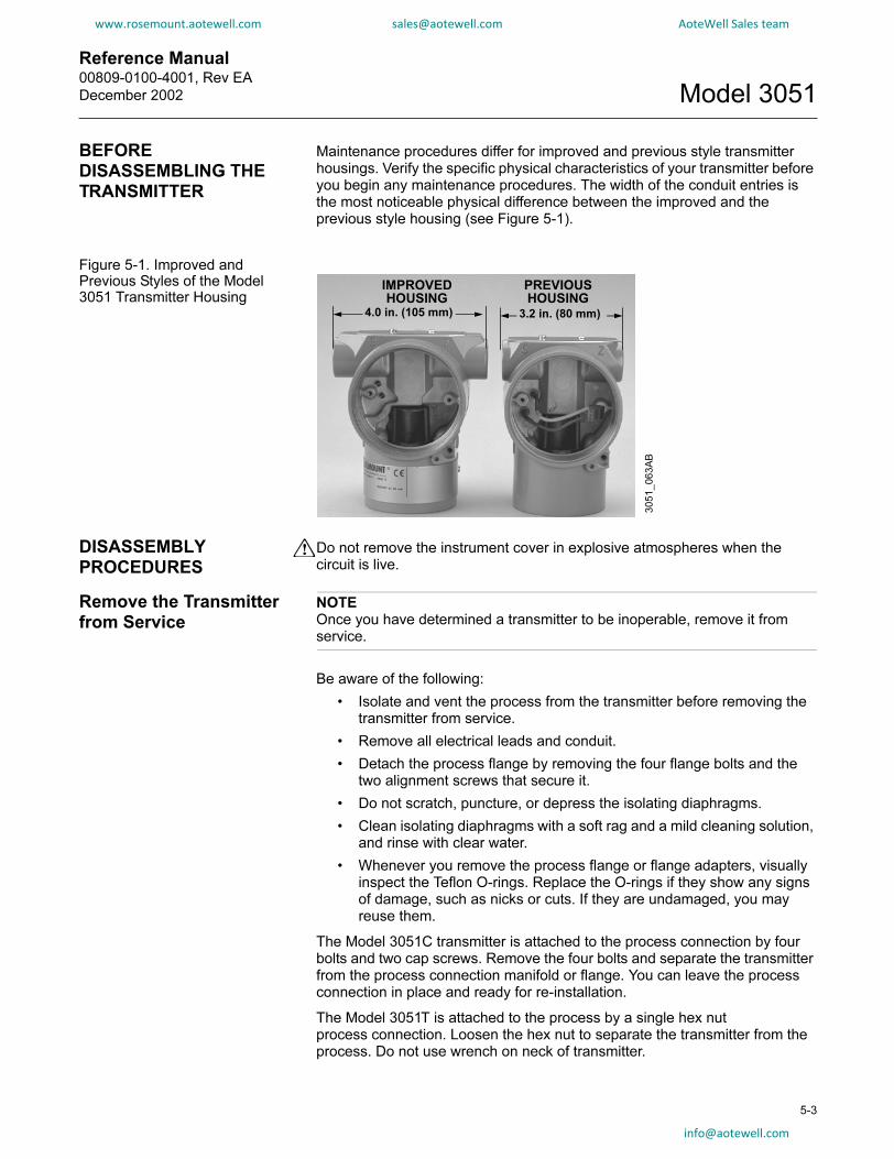
Reference Manual 00809-0100-4001, Rev EA
December 2002 Model 3051
www.rosemount.aotewell.com [email protected] AoteWell Sales team
BEFORE DISASSEMBLING THE TRANSMITTER
Maintenance procedures differ for improved and previous style transmitter housings. Verify the specific physical characteristics of your transmitter before you begin any maintenance procedures. The width of the conduit entries is the most noticeable physical difference between the improved and the previous style housing (see Figure 5-1).
Figure 5-1. Improved and Previous Styles of the Model 3051 Transmitter Housing
IMPROVED
HOUSING
PREVIOUS
HOUSING
4.0 in. (105 mm) 3.2 in. (80 mm)
3051_063A
B
DISASSEMBLY PROCEDURES
Do not remove the instrument cover in explosive atmospheres when the circuit is live.
Remove the Transmitter from Service
NOTEOnce you have determined a transmitter to be inoperable, remove it from service.
Be aware of the following:
• Isolate and vent the process from the transmitter before removing the transmitter from service.
• Remove all electrical leads and conduit.
• Detach the process flange by removing the four flange bolts and the two alignment screws that secure it.
• Do not scratch, puncture, or depress the isolating diaphragms.
• Clean isolating diaphragms with a soft rag and a mild cleaning solution, and rinse with clear water.
• Whenever you remove the process flange or flange adapters, visually inspect the Teflon O-rings. Replace the O-rings if they show any signs of damage, such as nicks or cuts. If they are undamaged, you may reuse them.
The Model 3051C transmitter is attached to the process connection by four bolts and two cap screws. Remove the four bolts and separate the transmitter from the process connection manifold or flange. You can leave the process connection in place and ready for re-installation.
The Model 3051T is attached to the process by a single hex nutprocess connection. Loosen the hex nut to separate the transmitter from the process. Do not use wrench on neck of transmitter.
info@
5-3
aotewell.com

Reference Manual00809-0100-4001, Rev EA
December 2002Model 3051
www.rosemount.aotewell.com [email protected] AoteWell Sales team
Remove the Terminal Block
5-4
Electrical connections are located on the terminal block in the compartment labelled “FIELD TERMINALS.”
Loosen the two small screws located at the 9 o'clock and 4 o'clock positions, and pull the entire terminal block out to remove it.
NOTEIf removing the terminal block from the housing of a previous version of the transmitter, you will have to manually disconnect the power leads from the rear of the terminal block before completely separating it from the housing.
Remove theElectronics Board
The transmitter electronics board is located in the compartment opposite the terminal side. To remove the electronics board perform the following procedure:
1. Remove the housing cover opposite the field terminal side.
2. Loosen the two captive screws that anchor the board to the housing. The electronics board is electrostatically sensitive; observe handling precautions for static-sensitive components.
NOTEIf you are disassembling a transmitter with a LCD display, loosen the two captive screws that are visible on the right and left side of the meter display. The two screws anchor the LCD display to the electronics board and the electronics board to the housing.
3. Slowly pull the electronics board out of the housing. With the two captive screws free of the transmitter housing, only the sensor module ribbon cable holds the board to the housing.
NOTEPrevious versions of the electronics board utilize a snap-in power plug and receptacle. Carefully unsnap the power plug from the receptacle to free the board from the power cord.
4. Disconnect the sensor module ribbon cable to release the electronics board from the transmitter.
Figure 5-2. Ribbon Cable view
Ribbon Cable view
3051-6
7A
C, 68A
C

Reference Manual 00809-0100-4001, Rev EA
December 2002 Model 3051
www.rosemount.aotewell.com [email protected] AoteWell Sales team
Remove the Sensor Module from the Electronics Housing
1. Carefully tuck the cable connector completely inside of the internal shroud.
NOTEDo not remove the housing until after you tuck the cable connector completely inside of the internal shroud. The shroud protects the cable from damage that can occur when you rotate the housing.
2. Loosen the housing rotation set screw with a 9/64-inch hex wrench, and back off one full turn.
IMPORTANTTo prevent damage to the sensor module ribbon cable, disconnect it from the electronics board before you remove the sensor module from the electrical housing.
3. Unscrew the housing from the module, making sure the shroud and sensor cable do not catch on the housing.
IMPORTANTMake sure the sensor ribbon cable and internal shroud remain completely free of the housing as you rotate it. Damage can occur to the cable if the internal shroud and sensor cable become hung up and rotate with the housing.
REASSEMBLY PROCEDURES
1. Inspect all cover and housing (non-process wetted) O-rings and replace if necessary. Lightly grease with silicone lubricant to ensure a good seal.
2. Carefully tuck the cable connector completely inside the internal shroud. To do so, turn the shroud and cable counterclockwise one rotation to tighten the cable.
3. Lower the electronics housing onto the module. Guide the internal shroud and cable through the housing and into the external shroud.
4. Turn the housing clockwise the fasten it to the module.
IMPORTANTTo prevent damage to the cable connector, watch the cable and shroud as you attach the housing to the module. Make sure the cable connector does not slip out of the internal shroud and begin to rotate with the housing. Reinsert the cable connector into the shroud if it escapes before the housing is fully fastened.
5. Thread the housing completely onto the sensor module. The housing must be no more than one full turn from flush with the sensor module to comply with explosion proof requirements.
6. Tighten the housing rotation set screw using a 9/64-inchhex wrench.
See “Safety Messages” on page 5-1 for complete warning information.
5-5

Reference Manual00809-0100-4001, Rev EA
December 2002Model 3051
5-6
www.rosemount.aotewell.com [email protected] AoteWell Sales team
NOTEElectronics board revision 5.3.163 or later (all shrouded designs) are able to verify alarm current levels. After replacing the transmitter electronics board, sensor module, or LCD meter, an alarm level test is recommended before returning the transmitter to service (see “Alarm Level Verification” on page 3-20).
Attach theElectronics Board
1. Remove the cable connector from its position inside of the internal shroud and attach it to the electronics board.
2. Insert the electronics board into the housing, making sure that the posts from the electronics housing properly engage the receptacles on the electronics board.
NOTEIf you are reassembling a previous version of the electronics board (or placing a new version of the electronics board in a previous version of the housing), attach the snap-in power connection to the receptacle on the board with the black and red wires routed toward the center of the board and below the white reed switch holder.
3. Tighten the captive mounting screws.
4. Replace the electronics housing cover. The transmitter covers must be engaged metal-to-metal to ensure a proper seal and to meet Explosion-Proof requirements.
NOTEElectronics board revision 5.3.163 or later (all shrouded designs) are able to verify alarm current levels. After replacing the transmitter electronics board, sensor module, or LCD meter, an alarm level test is recommended before returning the transmitter to service (see “Alarm Level Verification” on page 3-20).
Install the Terminal Block
Gently slide the terminal block into place, making sure the posts from the electronics housing properly engage the receptacles on the terminal block. Tighten the captive screws and replace the electronics housing cover. The transmitter covers must be fully engaged to meet Explosionp-Proof requirements.NOTEIf you are reassembling a previous version of the terminal block, attach the black and red wires to the back side of the block before you insert it into the electronics housing.

Reference Manual 00809-0100-4001, Rev EA
December 2002 Model 3051
www.rosemount.aotewell.com [email protected] AoteWell Sales team
Reassemble the Process Sensor Body
1. Visually inspect the Teflon sensor module O-rings. If the O-rings are undamaged, you may reuse them. If the O-rings show signs of damage, such as nicks or cuts, or if there is any doubt about their ability to seal properly, replace them with new O-rings.
NOTEIf you are replacing the O-rings, be careful not to scratch the O-ring grooves or the surface of the isolating diaphragm when removing the damaged O-rings.
2. Install the process flange on the sensor module. To hold the process flange in place, install the two hex head alignment screws. While these screws are not pressure retaining, tighten the hex head alignment screws to 33 in-lbs to ensure proper alignment. Do not overtighten; this will affect the module/flange alignment.
3. Install the appropriate flange bolts.
a. IF the installation requires a 1/4–18 NPT mounting, THEN use four 1.75-inch flange bolts. Go to step f.
b. IF the installation requires a 1/2–14 NPT mounting, THEN use four 2.88-inch process flange/adapter bolts. EXCEPTION: For gage pressure configurations, use two 2.88-inch bolts and two 1.75-inch bolts. Go to step d.
c. IF the installation uses a three-valve manifold (differential pressure applications only), THEN use four 2.25-inch manifold flange bolts. Go to step e.
d. Hold the flange adapters and adapter O-rings in place while finger-tightening the bolts. Go to step g.
e. Align the process flange with the three-valve manifold.
f. Finger tighten the bolts.
g. Tighten the bolts to the initial torque value using a crossed pattern. See Table 5-2 for appropriate torque values.
h. Tighten the bolts to the final torque value using a crossed pattern. See Table 5-2 for appropriate torque values. When fully tightened, the bolts should extend through the top of the module housing.
i. If the installation uses a three-valve manifold, then install flange adapters on the process end of the manifold using the 1.75-inch flange bolts supplied with the transmitter.
5-7

Reference Manual00809-0100-4001, Rev EA
December 2002Model 3051
www.rosemount.aotewell.com [email protected] AoteWell Sales team
Table 5-2. Bolt InstallationTorque Values
5-8
4. IF you replaced the Teflon sensor module O-rings, THENre-torque the flange bolts after installation to compensate forcold flow.
5. Install the drain/vent valve.
a. Apply sealing tape to the threads on the seat. Starting at the base of the valve with the threaded end pointing toward the installer, apply two clockwise turns of the sealing tape.
b. Take care to place the opening on the valve so that process fluid will drain toward the ground and away from personnel when the valve is opened.
c. Tighten the drain/vent valve to 350 in.-lb. (39.54 N-m).
NOTEAfter replacing O-rings on Range 1 transmitters and re-installing the process flange, expose the transmitter to a temperature of 185 °F (85 °C) for two hours. Then re-tighten the flange bolts in a cross pattern, and again expose the transmitter to a temperature of 185 °F (85 °C) for two hours before calibration.
Bolt Material Initial Torque Value Final Torque Value
CS-ASTM-A445 Standard 300 in.-lb (34 N-m) 650 in.-lb (73 N-m)
316 SST—Option L4 150 in.-lb (17 N-m) 300 in.-lb (34 N-m)
ASTM-A-193-B7M—Option
L5
300 in.-lb (34 N-m) 650 in.-lb (73 N-m)
Monel—Option L6 300 in.-lb (34 N-m) 650 in.-lb (73 N-m)

Reference Manual 00809-0100-4001, Rev EA
December 2002 Model 3051
www.rosemount.aotewell.com [email protected] AoteWell Sales team
Appendix A Reference Information
www.rosemount.com
Performance Specifications . . . . . . . . . . . . . . . . . . . . . . . page A-1
Detailed Performance Specifications . . . . . . . . . . . . . . . . page A-2
Functional Specifications . . . . . . . . . . . . . . . . . . . . . . . . . page A-6
Physical Specifications . . . . . . . . . . . . . . . . . . . . . . . . . . . page A-11
Dimensional Drawings . . . . . . . . . . . . . . . . . . . . . . . . . . . . page A-13
Ordering Information . . . . . . . . . . . . . . . . . . . . . . . . . . . . . page A-21
Parts List . . . . . . . . . . . . . . . . . . . . . . . . . . . . . . . . . . . . . . . page A-35
Options . . . . . . . . . . . . . . . . . . . . . . . . . . . . . . . . . . . . . . . . page A-45
HART Protocol C1 Option Configuration Data Sheet . . . page A-50
PERFORMANCE SPECIFICATIONS
Total Performance is based on combined errors of reference accuracy, ambient temperature effect, and static pressure effect.
Model 3051C (Ranges 2–5), Model 3051T
Reference Accuracy
±0.075% of span
Total Performance
±0.15% of span for ±50 °F (28 °C) temperature changes, up to 1000 psi (6,9 MPa) line
pressure (CD only), from 1:1 to 5:1 rangedown.
Stability
±0.125% of URL for 5 years for ±50 °F (28 °C) temperature changes, and up to 1000 psi (6,9
MPa) line pressure.
Dynamic Performance Total Response Time (Td + Tc)
HART output: 100 ms
Model 3051CD, Low/Draft Range (Ranges 0–1)
Reference Accuracy
±0.10% of span
Stability
±0.2% of URL for 1 year under reference conditions
Model 3051P—Reference Class
Reference Accuracy
±0.05% of span
Total Performance
±0.10% of span for ±50 °F (28 °C) temperature changes, up to 1000 psi (6,9 MPa) line
pressure, from 1:1 to 5:1 rangedown

Reference Manual00809-0100-4001, Rev EA
December 2002Model 3051
A-2
www.rosemount.aotewell.com [email protected] AoteWell Sales team
Stability
±0.125% of URL for 5 years for ±50 °F (28 °C) temperature changes, and up to 1000 psi
(6,9 MPa) line pressure
Dynamic Performance Total Response Time (Td + Tc)
100 ms
Model 3051L—Liquid Level
Reference Accuracy
±0.075% of span
Model 3051H—High Process Temperature
Reference Accuracy
±0.075% of span
Stability
±0.1% of URL for 12 months for Ranges 2 and 3
±0.2% of URL for 12 months for Ranges 4 and 5
DETAILED PERFORMANCE SPECIFICATIONS
For zero-based spans, reference conditions, silicone oil fill, SST materials, Coplanar flange (Model 3051C) or 1/2 in.- 18 NPT (Model 3051T) process connections, digital trim values set to equal range points.
Reference Accuracy
Stated reference accuracy includes hysteresis, terminal-based linearity and repeatability.Model 3051CD Ranges 2–5 and 3051CG
±0.075% of span for spans less than 10:1, accuracy =
Model 3051CD Range 1
±0.10% of span for spans less than 15:1, accuracy =
Model 3051CD Range 0
±0.10% of span for spans less than 2:1, accuracy = ±0.05% of URL
Model 3051T/CA Ranges 1–5
±0.075% of span for spans less than 10:1, accuracy =
Model 3051CA Range 0
±0.075% of span for spans less than 5:1, accuracy =
Model 3051H/3051L
±0.075% of span for spans less than 10:1, accuracy =
Model 3051P
±0.05% of span
0.025 0.005+URL
Span--------------- % of Span±
0.025 0.005+URL
Span--------------- % of Span±
0.0075URL
Span--------------- % of Span±
0.025 0.01+URL
Span--------------- % of Span±
0.025 0.005+URL
Span--------------- % of Span±

Reference Manual 00809-0100-4001, Rev EA
December 2002 Model 3051
www.rosemount.aotewell.com [email protected] AoteWell Sales team
Ambient Temperature Effect per 50 °F (28 °C)
Model 3051CD/CG
Range 2 - 5:±(0.0125% URL + 0.0625% span) from 1:1 to 5:1
±(0.025% URL + 0.125% span) from 5:1 to 100:1
Range 1: ±(0.1% URL + 0.25% span) from 1:1 to 30:1
±(0.147% URL + 0.15% span) greater than 30:1
Range 0: ±(0.25% URL + 0.05% span)
Model 3051CA
Range 1 - 4: ±(0.025% URL + 0.125% span) from 1:1 to 30:1
±(0.035% URL + 0.125% span) from 30:1 to 100:1
Range 0: ± (0.1% URL +0.25% span)
Model 3051P
All ranges: ±(0.006% URL + 0.03% span)
Model 3051H
All ranges: ±(0.025% URL + 0.125% span + 0.35 inH2O)
For spans below 30:1 rangedown:
±(0.035% URL + 0.125% span + 0.35 inH2O)
Model 3051L
See Rosemount Inc. Instrument Toolkit™ software.
Model 3051T
Ranges 2- 4: ±(0.025% URL + 0.125% span) from 1:1 to 30:1
±(0.035% URL + 0.125% span) from 30:1 to 100:1
Range 5: ±(0.1% URL + 0.15% span)
Range 1: ±(0.025% URL + 0.125% span) from 1:1 to 10:1
±(0.05% URL + 0.125% span) from 10:1 to 100:1
A-3

Reference Manual00809-0100-4001, Rev EA
December 2002Model 3051
www.rosemount.aotewell.com [email protected] AoteWell Sales team
Line Pressure Effect per 1000 psi (6,9 MPa)
A-4
Model 3051CD
Zero Error (can be calibrated out at line pressure)
±0.05% of URL for line pressures from 0 to 2000 psi
(0 to 13,7 MPa)
For line pressures above 2000 psi (13,7 MPa), see “Compensating for Line Pressure” on
page 4-12.
Range 0: ±0.125% of URL/100 psi (6,89 bar)
Range 1: ±0.25% of URL
Span Error
±0.1% of reading
Range 0: ±0.15% of reading/100 psi (6,89 bar)
Range 1: ±0.4% of reading
Model 3051P
Zero Error (can be calibrated out at line pressure)
±0.04% of URL
Span Error
±0.10% of reading
Model 3051HD
Zero Error (can be calibrated out at line pressure)
±0.1% of URL for line pressures from 0 to 2000 psi (0 to 13,7 MPa)
For line pressures above 2000 psi (13,7 MPa), see “Compensating for Line Pressure” on
page 4-12.
Span Error
±0.1% of reading
Dynamic Performance
Total Response Time (Td + Tc)(2):
Model 3051C/P, Ranges 2-5:
Range 1:
Range 0:
Model 3051T:
Model 3051H/L:
100 ms
255 ms
700 ms
100 ms
Consult factory
Dead Time (Td) 45 ms (nominal)
Update Rate 22 times per second(1) Dead time and update rate apply to all models and ranges; analog output only(2) Nominal total response time at 75 °F (24 °C) reference conditions.
Figure A-1. Typical Smart Transmitter Response Time
3051-3
051_17A
TcTd
Td = Dead TimeTc = Time Constant
Pressure Released
Response Time = Td+Tc
63.2% of TotalStep Change
Time4mA
20mA
9.89mA
Transmitter 4–20 mA Output vs. Time

Reference Manual 00809-0100-4001, Rev EA
December 2002 Model 3051
www.rosemount.aotewell.com [email protected] AoteWell Sales team
Mounting Position Effects
Model 3051C/P
Zero shifts up to ±1.25 inH2O (3,11 mbar),
which can be calibrated out. No span effect.
Model 3051H
Zero shifts up to ±5 inH2O (127 mmH2O),
which can be calibrated out. No span effect.
Model 3051L
With liquid level diaphragm in vertical plane,
zero shift of up to 1 inH2O (25,4 mmH2O).
With diaphragm in horizontal plane, zero shift of up to 5 inH2O (127 mmH2O)
plus extension length on extended units. All zero shifts can be calibrated out.
No span effect.
Model 3051T/CA
Zero shifts up to 2.5 inH2O (63,5 mmH2O), which can be calibrated out.
No span effect.
Vibration Effect
All ModelsMeasurement effect due to vibrations is negligible except at resonance
frequencies. When at resonance frequencies, vibration effect is less than
±0.1% of URL per g when tested between 15 and 2000 Hz in any axis relative
to pipe-mounted process conditions.
Power Supply Effect
All ModelsLess than ±0.005% of calibrated span per volt.
RFI Effects
All Models±0.1% of span from 20 to 1000 MHz and for field strength up to 30 V/m.
Shielded cable needed for 30 V/m.
Transient Protection (Option Code T1)
All Models
Meets IEEE Standard 587, Category B
1 kV crest (10 × 1 000 microseconds)
3 kV crest (8 × 20 microseconds)
6 kV crest (1,2 × 50 microseconds)
Meets IEEE Standard 472, Surge Withstand Capability
SWC 2,5 kV crest, 1 MHz wave form
General Specifications:
Response Time: < 1 nanosecond
Peak Surge Current: 5000 amps to housing.
Peak Transient Voltage: 100 V dc.
Loop Impedance: < 25 ohms
Applicable Standards: IEC 801-4, IEC 801-5
NOTE:
Calibrations at 68 °F (20 °C) per ASME Z210.1 (ANSI)
A-5
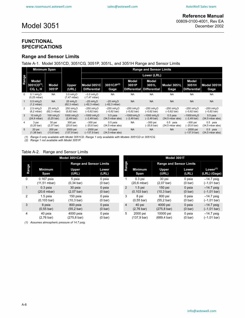
Reference Manual00809-0100-4001, Rev EA
December 2002Model 3051
www.rosemount.aotewell.com [email protected] AoteWell Sales team
FUNCTIONAL SPECIFICATIONS
Range and Sensor Limits
A-6
Table A-1. Model 3051CD, 3051CG, 3051P, 3051L, and 3051H Range and Sensor Limits
Ra
ng
e
Minimum Span Range and Sensor Limits
Model
3051CD(1),
CG, L, H
Model
3051P
Upper
(URL)
Lower (LRL)
Model 3051C
Differential
3051C/P(2)
Gage
Model
3051P
Differential
Model
3051L
Differential
Model 3051L
Gage
Model
3051H
Differential
Model 3051H
Gage
0 0.1 inH2O(0,25 mbar)
NA 3.0 inH2O(7,47 mbar)
–3.0 inH2O(-7,47 mbar)
NA NA NA NA NA NA
1 0.5 inH2O(1,2 mbar)
NA 25 inH2O(62,3 mbar)
–25 inH2O(–62,3 mbar)
–25 inH2O(–62,3 mbar)
NA NA NA NA NA
2 2.5 inH2O (6,2 mbar)
25 inH2O (62,3 mbar)
250 inH2O(0,62 bar)
–250 inH2O(–0,62 bar)
–250 inH2O(–0,62 bar)
–250 inH2O(–0,62 bar)
–250 inH2O(–0,62 bar)
–250 inH2O(–0,62 bar)
–250 inH2O(–0,62 bar)
–250 inH2O (–0,62 bar)
3 10 inH2O (24,9 mbar)
100 inH2O (0,25 bar)
1000 inH2O (2,49 bar)
–1000 inH2O (–2,49 bar)
0.5 psia
(34,5 mbar abs)–1000 inH2O (–2,49 bar)
–1000 inH2O (–2,49 bar)
0.5 psia(34,5 mbar abs)
–1000 inH2O (–2,49 bar)
0.5 psia(34,5 mbar abs)
4 3 psi (0,20 bar)
30 psi (2,07 bar)
300 psi (20,6 bar)
–300 psi(–20,6 bar)
0.5 psia
(34,5 mbar abs)NA –300 psi
(–20,6 bar)0.5 psia
(34,5 mbar abs)–300 psi
(–20,6 bar)0.5 psia
(34,5 mbar abs)
5 20 psi (1,38 bar)
200 psi (13,8 bar)
2000 psi (137,9 bar)
– 2000 psi(–137,9 bar)
0.5 psia(34,5 mbar abs)
NA NA NA – 2000 psi (–137,9 bar)
0.5 psia(34,5 mbar abs)
(1) Range 0 only available with Model 3051CD. Range 1 only available with Models 3051CD or 3051CG.(2) Range 1 not available with Model 3051P.
Table A-2. Range and Sensor Limits
Model 3051CA
Ra
ng
e
Model 3051T
Ra
ng
e
Minimum
Span
Range and Sensor Limits
Minimum
Span
Range and Sensor Limits
Lower(1)
(LRL) (Gage)
Upper
(URL)
Lower
(LRL)
Upper
(URL)
Lower
(LRL)
0 0.167 psia
(11,51 mbar)
5 psia
(0,34 bar)
0 psia
(0 bar)
1 0.3 psi
(20,6 mbar)
30 psi
(2,07 bar)
0 psia
(0 bar)
–14.7 psig
(–1,01 bar)
1 0.3 psia
(20,6 mbar)
30 psia
(2,07 bar)
0 psia
(0 bar)
2 1.5 psi
(0,103 bar)
150 psi
(10,3 bar)
0 psia
(0 bar)
–14.7 psig
(–1,01 bar)
2 1.5 psia
(0,103 bar)
150 psia
(10,3 bar)
0 psia
(0 bar)
3 8 psi
(0,55 bar)
800 psi
(55,2 bar)
0 psia
(0 bar)
–14.7 psig
(–1,01 bar)
3 8 psia
(0,55 bar)
800 psia
(55,2 bar)
0 psia
(0 bar)
4 40 psi
(2,76 bar)
4000 psi
(275,8 bar)
0 psia
(0 bar)
–14.7 psig
(–1,01 bar)
4 40 psia
(2,76 bar)
4000 psia
(275,8 bar)
0 psia
(0 bar)
5 2000 psi
(137,9 bar)
10000 psi
(689,4 bar)
0 psia
(0 bar)
–14.7 psig
(–1,01 bar)
(1) Assumes atmospheric pressure of 14.7 psig.

Reference Manual 00809-0100-4001, Rev EA
December 2002 Model 3051
www.rosemount.aotewell.com [email protected] AoteWell Sales team
Zero and Span Adjustment Requirements(HART and Low Power)
Zero and span values can be set anywhere within the range limits stated in
Table A-1 and Table A-2.
Span must be greater than or equal to the minimum span stated in Table A-1
and Table A-2.
Service
Liquid, gas, and vapor applications
4–20 mA (Output Code A)
Output
Two-wire 4–20 mA, user-selectable for linear or square root output. Digital process variable
superimposed on 4–20 mA signal, available to any host that conforms to the HART protocol.
Power Supply
External power supply required. Standard transmitter (4–20 mA) operates on 10.5 to 55 V dc
with no load.
Load Limitations
Maximum loop resistance is determined by the voltage level of the external power supply, as
described by:
Low Power (Output Code M)
Output
Three wire 1–5 V dc or 0.8–3.2 V dc (Option Code C2) user-selectable output. Also user
selectable for linear or square root output configuration. Digital process variable
superimposed on voltage signal, available to any host conforming to the HART protocol.
Low-power transmitter operates on 6–12 V dc with no load.
Power Consumption
3,0 mA, 18–36 mW
Minimum Load Impedance
100 kΩ (Vout wiring)
Indication
Optional 5-digit LCD display
Voltage (V dc)
Lo
ad
(O
hm
s)
Communication requires a minimum loop resistance of 250 ohms.
(1) For CSA approval, power supply must not exceed 42.4 V.
Max. Loop Resistance = 43.5 (Power Supply Voltage – 10.5)
OperatingRegion
A-7

Reference Manual00809-0100-4001, Rev EA
December 2002Model 3051
A-8
www.rosemount.aotewell.com [email protected] AoteWell Sales team
Overpressure Limits
Transmitters withstand the following limits without damage:
Model 3051CD/CG
Range 0: 750 psi (51,7 bar)
Range 1: 2000 psig (137,9 bar)
Ranges 2–5: 3626 psig (250 bar)
Model 3051CA
Range 0: 60 psia (4,14 bar)
Range 1: 750 psia (51,7 bar)
Range 2: 300 psia (20,7 bar)
Range 3: 1600 psia (110,3 bar)
Range 4: 6000 psia (413,7 bar)
Model 3051H
All Ranges: 3626 psig (25 MPa)
Model 3051TG/TA
Range 1: 750 psi (51,7 bar)
Range 2: 1500 psi (103,4 bar)
Range 3: 1600 psi (110,3 bar)
Range 4: 6000 psi (413,7 bar)
Range 5: 15000 psi (1034,2 bar)
Model 3051PG
Ranges 2-5: 3626 psig (250 bar)
Model 3051PD
Ranges 2 and 3: 2000 psig (13,8 MPa)For Model 3051L or Level Flange Option Codes FA, FB, FC, FD, FP, and FQ, limit is 0 psia to the flange rating or sensor rating, whichever is lower.
TABLE 1. Model 3051L and Level Flange Rating Limits
Standard Type CS Rating SST Rating
ANSI/ASME Class 150 285 psig 275 psig
ANSI/ASME Class 300 740 psig 720 psig
ANSI/ASME Class 600 1480 psig 1440 psig
At 100 °F (38 °C), the rating decreases with increasing temperature.
DIN PN 10–40 40 bar 40 bar
DIN PN 10/16 16 bar 16 bar
DIN PN 25/40 40 bar 40 bar
At 248 °F (120 °C), the rating decreases with increasing temperature.

Reference Manual 00809-0100-4001, Rev EA
December 2002 Model 3051
www.rosemount.aotewell.com [email protected] AoteWell Sales team
Static Pressure Limit
Model 3051CD Only
Operates within specifications between static line pressures of 0.5 psia and 3626 psig (4500
psig for Option Code P9).
Range 0: 0.5 psia and 750 psig
Range 1: 0.5 psia and 2000 psig
Model 3051PD Only
Operates within specifications between static line pressures of 0.5 psia and 2000 psig.
Burst Pressure Limits
Burst pressure on Coplanar, traditional, or Model 3051H process flange is
10000 psig (69 MPa).
Burst pressure for the Model 3051T is
Ranges 1–4: 11000 psi (75,8 MPa)
Range 5: 26000 psig (179 MPa)
Failure Mode Alarm
Output Code A
If self-diagnostics detect a gross transmitter failure, the analog signal will be driven either
below 3.75 mA or to 21.75 mA to alert the user. High or low alarm signal is user-selectable by
internal jumper.
Output Code M
If self-diagnostics detect a gross transmitter failure, the analog signal will be driven either
below 0.94 V or above 5.4 V to alert the user (below 0.75 V or above 4.4 V for Option C2).
High or low alarm signal is user-selectable by internal jumper.
Output Code F and W
If self-diagnostics detect a gross transmitter failure, that information gets passed as a status
along with the process variable.
Temperature Limits
Ambient
–40 to 185 °F (–46 to 85 °C)
With integral meter: –4 to 175 °F (–20 to 80 °C)
Storage
–50 to 230 °F (–46 to 110 °C)
With integral meter: –40 to 185 °F (–40 to 85 °C)
A-9

Reference Manual00809-0100-4001, Rev EA
December 2002Model 3051
A-10
www.rosemount.aotewell.com [email protected] AoteWell Sales team
Process
At atmospheric pressures and above. See Table A-3
Humidity Limits
0–100% relative humidity
Turn-On Time
Performance within specifications less than 2.0 seconds after power is
applied to the transmitter
Volumetric Displacement
Less than 0.005 in3 (0,08 cm3)
Damping
Analog output response to a step input change is user-selectable from 0 to
25.6 seconds for one time constant. This software damping is in addition to
sensor module response time.
Table A-3. Model 3051 Process Temperature Limits
Model 3051CD, 3051CG, 3051CA, 3051P
Silicone Fill Sensor(1)
(1) Process temperatures above 185 °F (85 °C) require derating the ambient limits by a 1.5:1 ratio (0.6:1 ratio for the Model 3051H).
with Coplanar Flange –40 to 250 °F (–40 to 121 °C)(2)
(2) 220 °F (104 °C) limit in vacuum service; 130 °F (54 °C) for pressures below 0.5 psia.
with Traditional Flange –40 to 300 °F (–40 to 149 °C)(2)(3)
(3) 3051CD0 process temperature limits are –40 to 212 °F (–45 to 100 °C)
with Level Flange –40 to 300 °F (–40 to 149 °C)(2)
with Model 305 Integral Manifold –40 to 300 °F (–40 to 149 °C)(2)
Inert Fill Sensor(1) 0 to 185 °F (–18 to 85 °C)(4) (5)
(4) 160 °F (71 °C) limit in vacuum service.(5) Not available for Model 3051CA.
Model 3051H (Process Fill Fluid)
D.C.® Silicone 200(1) –40 to 375 °F (–40 to 191 °C)
Inert(1) –50 to 350 °F (–45 to 177 °C)
Neobee M-20®(1) 0 to 375 °F (–18 to 191 °C)
Model 3051T (Process Fill Fluid)
Silicone Fill Sensor(1) –40 to 250 °F (–40 to 121 °C)(2)
Inert Fill Sensor(1) –22 to 250 °F (–30 to 121 °C)(2)
Model 3051L Low-Side Temperature Limits
Silicone Fill Sensor(1) –40 to 250 °F (–40 to 121 °C)(2)
Inert Fill Sensor(1) 0 to 185 °F (–18 to 85 °C)(2)
Model 3051L High-Side Temperature Limits (Process Fill Fluid)
Syltherm® XLT –100 to 300 °F (–73 to 149 °C)
D.C. Silicone 704® 60 to 400 °F (15 to 205 °C)
D.C. Silicone 200 –40 to 400 °F (–40 to 205 °C)
Inert –50 to 350 °F (–45 to 177 °C)
Glycerin and Water 0 to 200 °F (–18 to 93 °C)
Neobee M-20 0 to 400 °F (–18 to 205 °C)
Propylene Glycol and Water 0 to 200 °F (–18 to 93 °C)

Reference Manual 00809-0100-4001, Rev EA
December 2002 Model 3051
www.rosemount.aotewell.com [email protected] AoteWell Sales team
PHYSICAL SPECIFICATIONS
Electrical Connections1/2–14 NPT, PG 13.5, G1/2, and M20 × 1.5 (CM20) conduit. HART interface
connections fixed to terminal block.
Process Connections
All Models except 3051L and 3051T1/4–18 NPT on 21/8-in. centers1/2–14 NPT on 2-, 21/8-, or 21/4-in. centers
Model 3051L
High pressure side: 2-, 3-, or 4-in., ASME B 16.5 (ANSI) Class 150, 300 or 600 flange; 50, 80
or 100 mm, PN 40 or 10/16 flange
Low pressure side: 1/4–18 NPT on flange 1/2–14 NPT on adapter
Model 3051T1/4–18 NPT, 1/2–14 NPT female, Non-Threaded instrument flange (available in SST for Range
1-4 transmitters only), G1/2 A DIN 16288 Male (available in SST for Range 1–4 transmitters
only), or Autoclave type F-250-C (Pressure relieved 9/16–18 gland thread; 1/4 OD high
pressure tube 60° cone; available in SST for Range 5 transmitters only).
Process Wetted Parts
Drain/Vent Valves
316 SST, Hastelloy C®, or Monel material (Monel not available with Model 3051L or 3051H)
Process Flanges and Adapters
Plated carbon steel, CF-8M (Cast version of 316 SST, material per ASTM-A743), Hastelloy
C, or Monel
Wetted O-rings
Glass-filled TFE (Graphite-filled TFE with isolating diaphragm Option Code 6)
Process Isolating Diaphragms
Isolating Diaphragm Material
30
51
CD
/CG
30
51T
30
51
CA
30
51
P
30
51
H
316L SST • • • • •
Hastelloy C-276® • • • •
Monel • •
Tantalum • •
Gold-plated Monel • •
Gold-plated SST • •
A-11
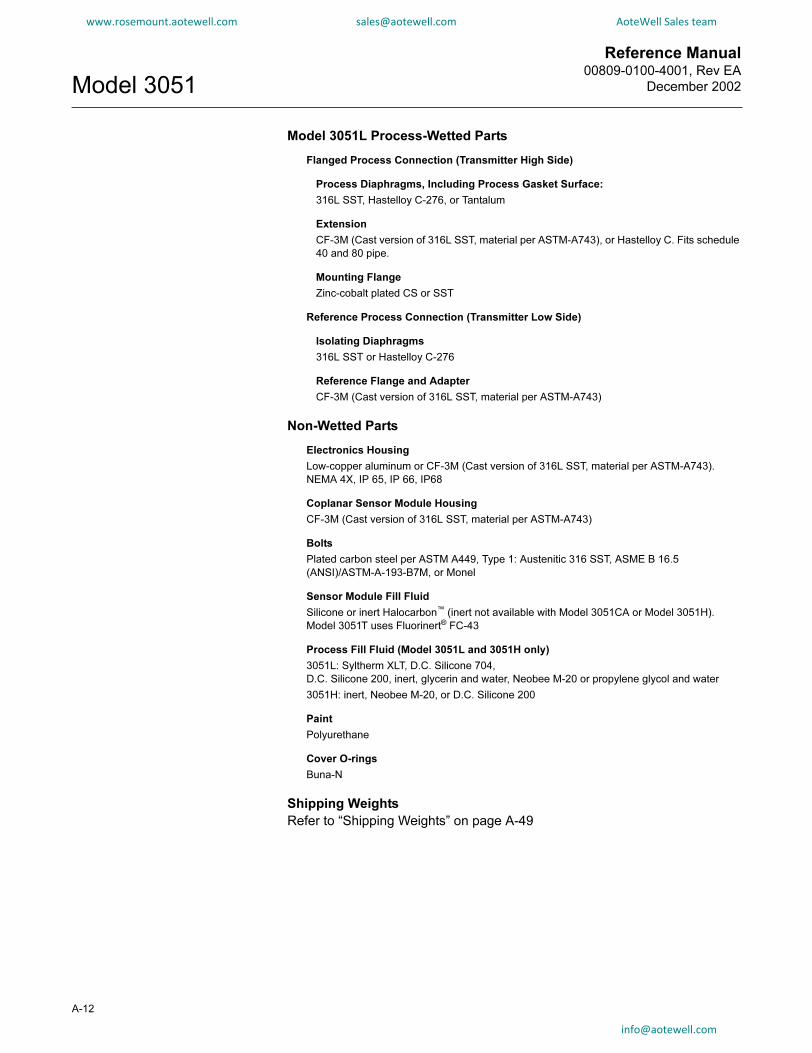
Reference Manual00809-0100-4001, Rev EA
December 2002Model 3051
A-12
www.rosemount.aotewell.com [email protected] AoteWell Sales team
Model 3051L Process-Wetted Parts
Flanged Process Connection (Transmitter High Side)
Process Diaphragms, Including Process Gasket Surface:
316L SST, Hastelloy C-276, or Tantalum
Extension
CF-3M (Cast version of 316L SST, material per ASTM-A743), or Hastelloy C. Fits schedule
40 and 80 pipe.
Mounting Flange
Zinc-cobalt plated CS or SST
Reference Process Connection (Transmitter Low Side)
Isolating Diaphragms
316L SST or Hastelloy C-276
Reference Flange and Adapter
CF-3M (Cast version of 316L SST, material per ASTM-A743)
Non-Wetted Parts
Electronics Housing
Low-copper aluminum or CF-3M (Cast version of 316L SST, material per ASTM-A743).
NEMA 4X, IP 65, IP 66, IP68
Coplanar Sensor Module Housing
CF-3M (Cast version of 316L SST, material per ASTM-A743)
Bolts
Plated carbon steel per ASTM A449, Type 1: Austenitic 316 SST, ASME B 16.5
(ANSI)/ASTM-A-193-B7M, or Monel
Sensor Module Fill Fluid
Silicone or inert Halocarbon™ (inert not available with Model 3051CA or Model 3051H).
Model 3051T uses Fluorinert® FC-43
Process Fill Fluid (Model 3051L and 3051H only)
3051L: Syltherm XLT, D.C. Silicone 704,
D.C. Silicone 200, inert, glycerin and water, Neobee M-20 or propylene glycol and water
3051H: inert, Neobee M-20, or D.C. Silicone 200
Paint
Polyurethane
Cover O-rings
Buna-N
Shipping Weights
Refer to “Shipping Weights” on page A-49

Reference Manual 00809-0100-4001, Rev EA
December 2002 Model 3051
www.rosemount.aotewell.com [email protected] AoteWell Sales team
DIMENSIONAL DRAWINGS
Model 3051 Exploded View
Certification Label
Span and ZeroAdjustments(1)
(Standard)
Electronics Housing
Terminal Block
Cover O-ring
Cover
Electronics Board
Nameplate
Sensor Module
Housing Rotation Set Screw(180° Maximum Housing Rotation
without Further Disassembly)
Flange Alignment Screw (Not Pressure Retaining)
Flange Bolts
Flange Adapters
Drain/Vent Valve
Coplanar Flange
Flange Adapter O-Ring
Process O-Ring
NOTEDimensions are in inches (millimeters).
3031B
08A
A-13

Reference Manual00809-0100-4001, Rev EA
December 2002Model 3051
A-14
www.rosemount.aotewell.com [email protected] AoteWell Sales team
Model 3051C Coplanar Flange Dimensional Drawing (Differential Pressure Transmitter Shown)
Coplanar Flange Mounting Configurations with Optional Bracket (B4) for 2-in. Pipe or Panel Mounting
PA
NE
L M
OU
NT
ING
PIP
E M
OU
NT
ING
6.4(163)
1/2–14 NPT on Optional Flange Adapters. Adapters can be rotated to give connection centers of 2.00 (51), 2.125 (54), or 2.25 (57).
0.75 (20) Clearancefor Cover Removal
Drain/Vent Valve
TransmitterCircuitry
Nameplate
4.3 (110)
5.0 (127)
0.75 (20) Clearance for Cover Removal
Terminal Connections
Coplanar Flange Process Connection Per DIN STD. IEC 61518 2.126 (54) ±0.012 in. Connection Centers
¼–18 NPT on Coplanar Flangefor Pressure Connection without the Use of Flange Adapters
NOTEDimensions are in inches (millimeters).
Housing RotationSet Screw
7.1(181) 8.2
(209)
4.1 (105)
Certification Label
1/2–14 NPTConduit Connection
(Two Places, OtherSizes Available)
3051-3
031A
06A
, B
06A
4.3
(110)
2.8
(72)
7.1
(181)
2.8
(71)
6.2
(156)
4.8
(120)
1.1 (28)
5/16 1½ Bolts for Panel Mounting(Not Supplied)
3/8–16 × 1¼ Boltsfor Mounting
to Transmitter
2.8 (71)
3.4 (85)
6.0
(152)
3.3(83)
2-inch U-Boltfor Pipe Mounting
3051-3
031A
04H
,I04A
,M04A
,L04A
,J04A
3/8–16 × 1¼ Boltsfor Mounting
to Transmitter
3.4 (85)
info
@ao tewell.com
Reference Manual 00809-0100-4001, Rev EA
December 2002 Model 3051
www.rosemount.aotewell.com [email protected] AoteWell Sales team
Traditional Flange Mounting Configurations with Optional Brackets for 2-in. Pipe or Panel Mounting
10.1 (257)
2.7 (67)
6.2 (158)
OPTION B2/B8:
TRADITIONAL FLANGE
PANEL MOUNTING
BRACKET
PANEL MOUNTING BRACKET
2.81(71)
NOTEDimensions are in inches (millimeters).
5/16 x 7/8 Bolts for PanelMounting (Not Supplied)
1.1 (28)
1.4 (33)
4.6 (116)
9.6 (243)
Impulse Piping
3.8 (95)
2.7 (67)
4.2 (106)
OPTION B1/B7/BA:
TRADITIONAL
FLANGE 2-IN. PIPE
MOUNTING
BRACKET
PIPE MOUNTING BRACKET
30
51
-30
31
J1
9D
, I1
9C
, E
19
C,
C1
9A
Traditional Flange (Options H2–H7) Dimensional Drawing
5.0(127)
4.3(110)
0.75 (20)Clearance for
Cover Removal
TransmitterCircuitry
TerminalConnections
Nameplate
1/2–14 NPT Conduit Connection (Two PlacesOther Sizes Available)
1.7 (43)
2.2(56)
1/4–18 NPT onTraditional Flange forPressure Connection
Without the Use ofFlange Adapters.
Connection Per DINSTD. IEC 61518
2.126 (54) ±0.012 in.Connection Centers
NOTEDimensions are in inches (millimeters).
3051-3
031E
30A
, D
30B
Certification Label
4.1(105)
7.9(202)
1.1(28)
HousingRotation
Set Screw
3.4 (87)
1.1 (28)
Drain/Vent
Valve
1/2–14 NPT on Optional Flange Adapters. Adapters Can Be Rotated to Give Connection Centers of 2.00 (51), 2.125 (54), or 2.25 (57).
info@aotewel
l.comA-15

Reference Manual00809-0100-4001, Rev EA
December 2002Model 3051
A-16
www.rosemount.aotewell.com [email protected] AoteWell Sales team
Model 3051T Dimensional Drawings
TerminalConnections
TransmitterCircuitry
Nameplate
NOTEDimensions are in inches (millimeters).
5.0(127)
4.3(110)
0.75 (20)Clearance for
Cover Removal
0.75 (20) Clearance for Cover Removal
1/2–14 NPTConduit
Connection (TwoPlaces, Other
Sizes Available)
Certification Label
HousingRotation
Set Screw
7.2(183)
4.1(105)
3051-3
051TC
6A
, T
B6A
Model 3051T Typical Mounting Configurations with Optional Mounting Bracket
3.5 (90)
NOTEDimensions are in inches (millimeters).
6.3(160)
PIPE MOUNTING
2(50)
6.2(156)
2.9(72)
4.3(110)
2.8 (71)
4.8 (120)
6.9 (175)
5.1(130)
PANEL MOUNTING
30
51
-30
51TA
4A
, T
B4
A,
TC
4A
info@a
o tewell.co m
Reference Manual 00809-0100-4001, Rev EA
December 2002 Model 3051
www.rosemount.aotewell.com [email protected] AoteWell Sales team
Model 3051H Pressure Transmitter Exploded View and Dimensional Drawings
Process Isolating Diaphragm
High Side Process Flange
Low Side Process Flange
Drain/Vent Valve
Flange Bolts
SecondaryFilled System
Sensor Module
3051-3
051H
B2G
5.0(127)
4.3(110)
0.75 (19) Clearancefor Cover Removal
TransmitterCircuitry
Nameplate
Terminal Connections
0.75 (19)Clearance for Cover Removal
1/2–18 NPT on Process Flange forPressure Connection Without the
Use of Mounting Adapters
NOTEDimensions are in inches (millimeters).
Drain/VentValve
Housing RotationSet Screw
1.2 (30)
1.1 (28)
3.4 (86)
4.1(105)
10.8 (275)
9.0 (228)
1/2–14 NPT on Optional MountingAdapters. Adapters Can Be Rotated
to Give Adapter Connection Centers of2.00 (51), 2.1256 (54), or 2.25 (57).
Certification Label
1/2–14 NPTConduit Connection
(Two Places, OtherSizes Available)
30
51
-30
51
i01
A,
H0
1B
info@aotewell.
coA-17
m

Reference Manual00809-0100-4001, Rev EA
December 2002Model 3051
A-18
www.rosemount.aotewell.com [email protected] AoteWell Sales team
Model 3051H Mounting Brackets for 2-in. Pipe and Panel Mount (Option Code B5/B6)
PIP
E M
OU
NT
ING
CO
NF
IGU
RA
TIO
N
Impulse Piping
2.7 (67)
0.7 (16)
4.4 (109)
PA
NE
L M
OU
NT
ING
CO
NF
IGU
RA
TIO
N7/16–
20
3/4
Bo
lts
Su
pp
lie
d f
or
Att
ac
hin
g B
rac
ke
t to
Tra
ns
mit
ter
Impulse Piping
2.7(67)
NOTEDimensions are in inches (millimeters).
30
51
-30
31
G1
9A
, F
19
B,
30
51
Hb
3A
, H
A3
B
m
Reference Manual 00809-0100-4001, Rev EA
December 2002 Model 3051
www.rosemount.aotewell.com [email protected] AoteWell Sales team
Model 3051L Dimensional Drawings
Certification Label
Gasket
1(25)
Lower Housing
1/2–14 NPTMounting
Adapter(optional)
A
2-IN. FLANGE CONFIGURATION(FLUSH MOUNT ONLY)
4.1(105)
E F
Serrated FaceGasket Surface
Certification Label
A
Housing Rotation SetScrew
Extension2, 4, or 6 (51, 102, or 152)
1/2–14 NPT Mounting Adapter (optional)
3- AND 4-IN. FLANGE CONFIGURATION
E
4.1(105)
D
6.5 (165)
Flushing Connection
1 (25)
OPTIONAL FLUSHING CONNECTION RING(LOWER HOUSING)
F
E
1/2–14 NPT ConduitConnections (optional) 5.0
(127)
Terminal Connections0.75 (19) Clearance for
Cover Removal
Nameplate
Drain/Vent Valve
5.14(131)
8.2(209)
4.3(110)
1/4–18 NPT on Flange for PressureConnection without the Use of
Mounting Adapters
7.1(181)
Transmitter Circuitry 0.75 (19) Clearance for Cover Removal
NOTEDimensions are in inches (millimeters).
3051-3
031B
27A
, 27B
, 27C
, 3031B
27D
, C
27E
DIAPHRAGM ASSEMBLYAND MOUNTING FLANGE
CB
info@aotew
ell.coA-19
m

Reference Manual00809-0100-4001, Rev EA
December 2002Model 3051
A-20
www.rosemount.aotewell.com [email protected] AoteWell Sales team
Class Pipe Size
Flange
Thickness
Bolt Circle
Diameter
Outside
Diameter
No. of
Bolts
Bolt Hole
Diameter
Exten.
Diam.(1)
D
O.D. Gask.
Surf.
E
Proc. Side
F
ASME B 16.5
(ANSI) 150
2 (51) 1.12 (28) 4.75 (121) 6.0 (152) 4 0.75 (19) NA 3.6 (92) 2.12 (54)
3 (76) 1.31 (33) 6.0 (152) 7.5 (191) 4 0.75 (19) 2.58 (66) 5.0 (127) 3.5 (89)
4 (102) 1.31 (33) 7.5 (191) 9.0 (229) 8 0.75 (19) 3.5 (89) 6.2 (158) 4.5 (114)
ASME B 16.5
(ANSI) 300
2 (51) 1.25 (32) 5.0 (127) 6.5 (165) 8 0.75 (19) NA 3.6 (92) 2.12 (54)
3 (76) 1.50 (38) 6.62 (168) 8.25 (210) 8 0.88 (22) 2.58 (66) 5.0 (127) 3.5 (89)
4 (102) 1.62 (41) 7.88 (200) 10.0 (254) 8 0.88 (22) 3.5 (89) 6.2 (158) 4.5 (114)
ASME B 16.5
(ANSI) 600
2 (51) 1.12 (28) 5.0 (127) 6.5 (165) 8 0.75 (19) NA 3.6 (92) 2.12 (54)
3 (76) 1.37 (35) 6.62 (168) 6.62 (168) 8 0.88 (22) 2.58 (66) 5.0 (127) 3.5 (89)
DIN
PN 10–40
DN 50 26 mm 125 mm 165 mm 4 18 mm NA 4.0 (102) 2.5 (63)
DIN PN 25/40 DN 80 30 mm 160 mm 200 mm 8 18 mm 65 mm 5.4 (138) 3.7 (94)
DN 100 30 mm 190 mm 235 mm 8 22 mm 89 mm 6.2 (158) 4.5 (114)
DIN PN 10/16 DN 100 26 mm 180 mm 220 mm 8 18 mm 89 mm 6.2 (158) 4.5 (114)
(1) Tolerances are 0.040 (1,02), –0.020 (0,51)

Reference Manual 00809-0100-4001, Rev EA
December 2002 Model 3051
www.rosemount.aotewell.com [email protected] AoteWell Sales team
ORDERING INFORMATION
Model Transmitter Type (Select One) CD CG CA
3051CD Differential Pressure Transmitter • — —
3051CG Gage Pressure Transmitter — • —
3051CA Absolute Pressure Transmitter — — •
Model 3051CD Model 3051CG Model 3051CA
0(1) –3 to 3 inH2O/0.1 inH2O
(–7,5 to 7,5 mbar/0,25 mbar)
Not Applicable 0 to 5 psia/0.167 psia
(0 to 0,34 bar/11,5 mbar)
• — •
1 –25 to 25 inH2O/0.5 inH2O
(–62,2 to 62,2 mbar/1,2 mbar)
–25 to 25 inH2O/0.5 inH2O
(–62,2 to 62,2 mbar/1,2 mbar)
0 to 30 psia/0.3 psia
(0 to 2,1 bar/20,7 mbar)
• • •
2 –250 to 250 inH2O/2.5 inH2O
(–623 to 623 mbar/6,2 mbar)
–250 to 250 inH2O/2.5 inH2O
(–623 to 623 mbar/6,2 mbar)
0 to 150 psia/1.5 psia
(0 to 10,3 bar/0,1 bar)
• • •
3 –1000 to 1000 inH2O/10 inH2O
(–2,5 to 2,5 bar/25 mbar)
–407 to 1000inH2O/10in H2O
(–1,01 to 2,5 bar/25 mbar)
0 to 800 psia/8 psia
(0 to 55,2 bar/0,55 bar)
• • •
4 –300 to 300 psi/3 psi
(–20,7 to 20,7 bar/0,2 bar)
–14.7 to 300 psi/3 psi
(–1,01 to 20,7 bar/0,2 bar)
0 to 4000 psia/40 psia
(0 to 275,8 bar/2,8 bar)
• • •
5 –2000 to 2000 psi/20 psi
(–137,9 to137,9 bar/1,4 bar)
–14.7 to 2000 psig/20 psi
(–1,01 to 137,9 bar/1,4 bar)
Not Applicable • • —
NOTE: 3051CG lower range limit varies with atmospheric pressure.
Code Output CD CG CA
A 4–20 mA with Digital Signal Based on HART Protocol • • •
M Low-Power, 1–5 V dc with Digital Signal Based on HART Protocol (See Option C2 for 0.8–3.2 V dc)
NOTE: Not available with hazardous locations certification Options Codes I1, N1, E4, K6 and K8.
• • •
Code
Materials of Construction
CD CG CA
Process
Flange Type Flange Material Drain/Vent
2 Coplanar SST SST • • •
3 Coplanar Hastelloy C Hastelloy C • • •
4 Coplanar Monel Monel • • •
5 Coplanar Plated CS SST • • •
7 Coplanar SST Hastelloy C • • •
8 Coplanar Plated CS Hastelloy C • • •
0 Alternate Flange—See Options on page A-22 • • •
NOTE: Materials of Construction Codes 3, 7, and 8 meet NACE material recommendations per MR 01-75.
Code Isolating Diaphragm CD CG CA
2 316L SST • • •
3 Hastelloy C-276 (Meets NACE material recommendations per MR 01-75) • • •
4 Monel • • •
5 Tantalum (Available on Model 3051CD and CG, Ranges 2–5 only. Not available on Model 3051CA) • • —
6 Gold-plated Monel (Use in combination with O-ring Option Code B.) • • •
7 Gold-plated SST • • •
Code O-ring
A Glass-filled TFE • • •
B Graphite-filled TFE • • •
Code Fill Fluid CD CG CA
1 Silicone • • •
2 Inert fill (Halocarbon) • • —
Continued on next page
A-21

Reference Manual00809-0100-4001, Rev EA
December 2002Model 3051
www.rosemount.aotewell.com [email protected] AoteWell Sales team
Code Housing Material Conduit Entry Size CD CG CA
A Polyurethane-covered Aluminum ½–14 NPT • • •
B Polyurethane-covered Aluminum M20 × 1.5 (CM20) • • •
C Polyurethane-covered Aluminum PG 13.5 • • •
D Polyurethane-covered Aluminum G½ • • •
J SST ½–14 NPT • • •
K SST M20 × 1.5 (CM20) • • •
L SST PG 13.5 • • •
M SST G½ • • •
Code Alternate Flange Options (Requires Materials of Construction Code 0) CD CG CA
H2 Traditional Flange, 316 SST, SST Drain/Vent • • •
H3 Traditional Flange, Hastelloy C, Hastelloy C Drain/Vent • • •
H4 Traditional Flange, Monel, Monel Drain/Vent • • •
H7 Traditional Flange, 316 SST, Hastelloy C Drain/Vent • • •
HJ DIN Compliant Traditional Flange, SST, 7/16 in. Adapter/Manifold Bolting • • •
HK DIN Compliant Traditional Flange, SST, 10 mm Adapter/Manifold Bolting • • •
HL DIN Compliant Traditional Flange, SST, 12mm Adapter/Manifold Bolting
(not available on Model 3051CD0)
• • •
FA Level Flange, SST, 2 in., ANSI Class 150, Vertical Mount • • •
FB Level Flange, SST, 2 in., ANSI Class 300, Vertical Mount • • •
FC Level Flange, SST, 3 in., ANSI Class 150, Vertical Mount • • •
FD Level Flange, SST, 3 in., ANSI Class 300, Vertical Mount • • •
FP DIN Level Flange, SST, DN 50, PN 40, Vertical Mount • • •
FQ DIN Level Flange, SST, DN 80, PN 40, Vertical Mount • • •
NOTE: Option Codes H3 and H7 meet NACE material recommendations per MR 01-75.
Code Integral Mount Manifold Options
S5 Assemble to Model 305 Integral Manifold • • •
Code Integral Mount Primary Elements (Optional) CD CG CA
S4 Factory Assembly to Rosemount Primary Element (Annubar or Model 1195 Integral Orifice)
NOTE: With the primary element installed, the maximum operating pressure will equal the lesser of
either the transmitter or the primary element. Option is available for factory assembly to range 1–4 transmitters only.
• — —
Code
Diaphragm Seal Assemblies (Optional)
NOTE: Standard flange and adapter bolts are austenitic 316 SST. CD CG CA
S1 One Diaphragm Seal (Direct Mount or Capillary Connection Type) • • •
S2 Two Diaphragm Seals (Direct Mount or Capillary Connection Type) • — —
Code
Optional All Welded Diaphragm Seal Systems (for high vacuum applications)
NOTE: Standard flange and adapter bolts are austenitic 316 SST. CD CG CA
S7 One Diaphragm Seal, All-Welded System (Capillary Connection Type) • • •
S8 Two Diaphragm Seals, All-Welded System (Capillary Connection Type) • — —
S0 One Diaphragm Seal, All-Welded System (Direct Mount Connection Type) • • •
S9 Two Diaphragm Seals, All-Welded System (One Direct Mount and One Capillary Connection Type) • — —
Continued on next page
A-22

Reference Manual 00809-0100-4001, Rev EA
December 2002 Model 3051
www.rosemount.aotewell.com [email protected] AoteWell Sales team
Code Mounting Bracket Options CD CG CA
B4 Coplanar Flange Bracket for 2-in. Pipe or Panel Mounting, all SST • • •
B1 Traditional Flange Bracket for 2-in. Pipe Mounting, CS Bolts • • •
B2 Traditional Flange Bracket for Panel Mounting, CS Bolts • • •
B3 Traditional Flange Flat Bracket for 2-in. Pipe Mounting, CS Bolts • • •
B7 B1 Bracket with Series 300 SST Bolts • • •
B8 B2 Bracket with Series 300 SST Bolts • • •
B9 B3 Bracket with Series 300 SST Bolts • • •
BA SST B1 Bracket with Series 300 SST Bolts • • •
BC SST B3 Bracket with Series 300 SST Bolts • • •
Code Product Certification Options CD CG CA
Hazardous Locations Certifications
E5 FM Explosion-Proof Approval • • •
I5 FM Non-incendive and Intrinsic Safety Approval • • •
K5 FM Explosion-Proof and Intrinsic Safety Approval • • •
I1 CENELEC Intrinsic Safety and Dust Certification
NOTE: Not available with low-power Option Code M.
• • •
N1 CENELEC Type nL and Dust Certification
NOTE: Not available with low-power Option Code M.
• • •
E8 CENELEC Flame-Proof and Dust Certification • • •
E4 JIS Flame-Proof Certification
NOTE: Not available with low-power Option Code M.
• • •
C5 Measurement Canada Accuracy Approval
NOTE: Limited availability depending on transmitter type and range. Contact your Rosemount representative.
• • •
C6 Canadian Standards Association (CSA) Explosion-Proof and Intrinsic Safety Approval • • •
K6 Combination of CSA and CENELEC Explosion-Proof and Intrinsic Safety Approval
NOTE: Not available with low-power Option Code M.
• • •
KB Combination of FM and CSA Explosion-Proof and Intrinsic Safety Approvals • • •
K7 Combination of SAA Flame-Proof and Intrinsic Safety Approvals • • •
K8 Combination of CENELEC Flame-Proof and Intrinsic Safety Approvals
NOTE: Not available with low-power Option Code M.
• • •
I7 SAA Intrinsic Safety Certification • • •
E7 SAA Flame-Proof Certification • • •
N7 SAA Type N Certification • • •
Code Bolting Options CD CG CA
L4 Austenitic 316 SST Bolts • • •
L5 ASME B 16.5 (ANSI)/ASTM-A-193-B7M Bolts • • •
L6 Monel Bolts • • •
Code LCD Display (Optional) CD CG CA
M5 LCD display for Aluminum Housing (Housing Codes A, B, C, and D only) • • •
M6 LCD display for SST Housing (Housing Codes J, K, L, and M only) • • •
Continued on next page
A-23

Reference Manual00809-0100-4001, Rev EA
December 2002Model 3051
www.rosemount.aotewell.com [email protected] AoteWell Sales team
Code Other Options
Q4 Calibration Data Sheet • • •
Q8 Material Traceability Certification per EN 10204 3.1.B
NOTE: This option is available for the sensor module housing and Coplanar or traditional flanges and adapters (Model
3051C), and for the sensor module housing and low-volume Coplanar flange and adapter (Model 3051C with Option
Code S1).
• • •
QP Calibration certification and tamper evident seal • • •
QS Quality Certification for safety • • •
J1 Local Zero Adjustment Only
NOTE: Local zero and span adjustments are standard unless Option Code J1 or J3 is specified.
• • •
J3 No Local Zero or Span Adjustment
NOTE: Local zero and span adjustments are standard unless Option Code J1 or J3 is specified.
• • •
T1 Transient Protection Terminal Block
NOTE: Not available with hazardous locations certification Option Code I1, K6 or K8.
• • •
C1 Custom Software Configuration (Completed CDS 00806-0100-4001 required with order) • • •
C2 0.8–3.2 V dc Output with Digital Signal Based on HART Protocol (Output Code M only) • • •
C3 Gage Calibration (Model 3051CA4 only) — — •
C4 Analog Output Levels Compliant with NAMUR Recommendation NE43, 27-June-1996
NOTE: NAMUR-Compliant operation is pre-set at the factory and cannot be changed to
standard operation in the field.
• • •
CN Analog Output Levels Compliant with NAMUR Recommendation NE43, 27-June-1996:
Alarm Configuration–Low
NOTE: NAMUR-Compliant operation is pre-set at the factory and cannot bechanged to standard operation in the field.
• • •
P1 Hydrostatic Testing • • •
P2 Cleaning for Special Service • • •
P3 Cleaning for <1 PPM Chlorine/Fluorine • • •
P4 Calibrate at line pressure
Note: Specify Q48 on order for corresponding certificate
• • •
DF 1/2 -14 NPT flange adapter(s)— Material determined by flange material • • •
D7 Coplanar Flange Without Drain/Vent Ports • • •
D8 Ceramic Ball Drain/Vents • • •
D9 JIS Process Connection—RC ¼ Flange with RC ½ Flange Adapter • • •
P9 4500 psig Static Pressure Limit (Model 3051CD Ranges 2–5 only) • — —
V5(2) External Ground Screw Assembly • • •
Typical Model Number: 3051CD 2 A 2 2 A 1 A B4
(1) Model 3051CD0 is available only with Output Code A, Process Flange Code 0 (Alternate Flange H2, H7, HJ, or HK), Isolating Diaphragm Code 2, O-ring Code A, and Bolting Option L4.
(2) The V5 option is not needed with the T1 option; external ground screw assembly is included with the T1 option.
A-24
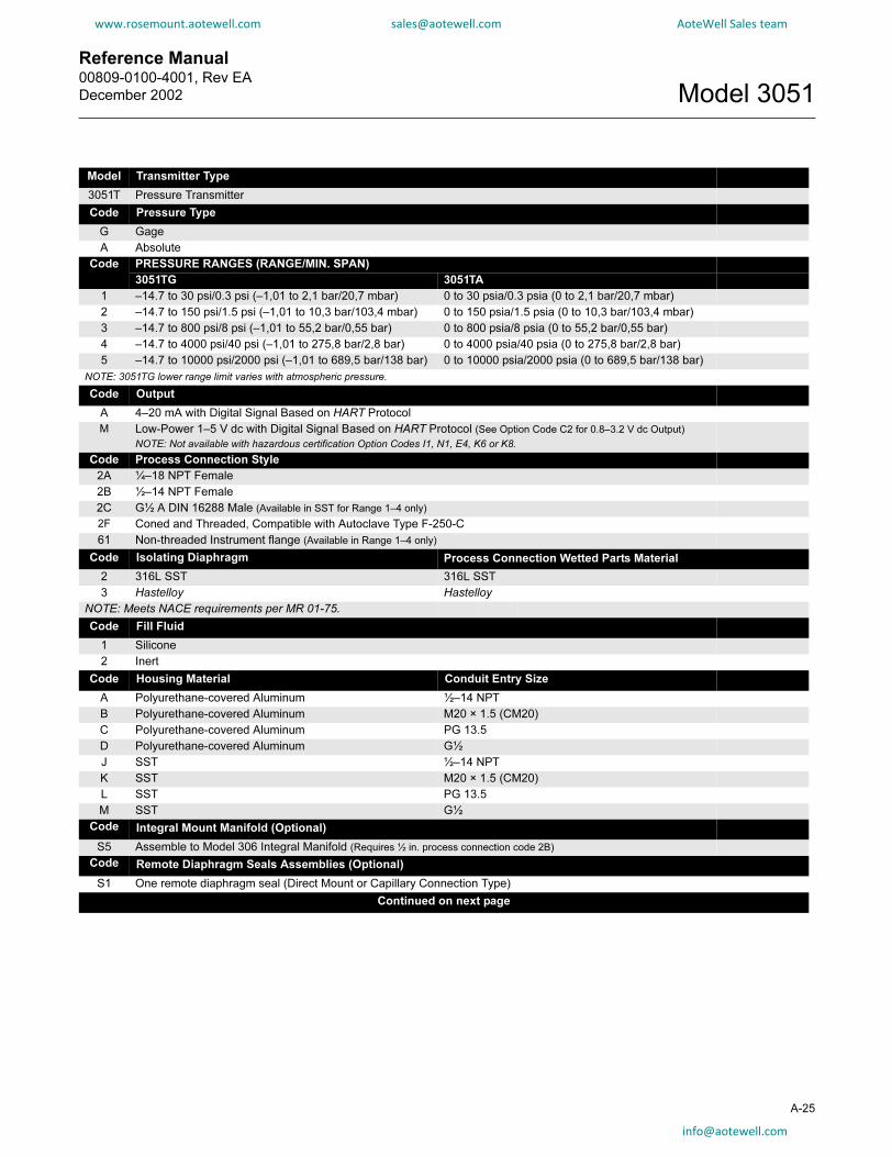
Reference Manual 00809-0100-4001, Rev EA
December 2002 Model 3051
www.rosemount.aotewell.com [email protected] AoteWell Sales team
Model Transmitter Type
3051T Pressure Transmitter
Code Pressure Type
G Gage
A Absolute
Code PRESSURE RANGES (RANGE/MIN. SPAN)
3051TG 3051TA
1 –14.7 to 30 psi/0.3 psi (–1,01 to 2,1 bar/20,7 mbar) 0 to 30 psia/0.3 psia (0 to 2,1 bar/20,7 mbar)
2 –14.7 to 150 psi/1.5 psi (–1,01 to 10,3 bar/103,4 mbar) 0 to 150 psia/1.5 psia (0 to 10,3 bar/103,4 mbar)
3 –14.7 to 800 psi/8 psi (–1,01 to 55,2 bar/0,55 bar) 0 to 800 psia/8 psia (0 to 55,2 bar/0,55 bar)
4 –14.7 to 4000 psi/40 psi (–1,01 to 275,8 bar/2,8 bar) 0 to 4000 psia/40 psia (0 to 275,8 bar/2,8 bar)
5 –14.7 to 10000 psi/2000 psi (–1,01 to 689,5 bar/138 bar) 0 to 10000 psia/2000 psia (0 to 689,5 bar/138 bar)
NOTE: 3051TG lower range limit varies with atmospheric pressure.
Code Output
A 4–20 mA with Digital Signal Based on HART Protocol
M Low-Power 1–5 V dc with Digital Signal Based on HART Protocol (See Option Code C2 for 0.8–3.2 V dc Output)
NOTE: Not available with hazardous certification Option Codes I1, N1, E4, K6 or K8.
Code Process Connection Style
2A ¼–18 NPT Female
2B ½–14 NPT Female
2C G½ A DIN 16288 Male (Available in SST for Range 1–4 only)
2F Coned and Threaded, Compatible with Autoclave Type F-250-C
61 Non-threaded Instrument flange (Available in Range 1–4 only)
Code Isolating Diaphragm Process Connection Wetted Parts Material
2 316L SST 316L SST
3 Hastelloy Hastelloy
NOTE: Meets NACE requirements per MR 01-75.
Code Fill Fluid
1 Silicone
2 Inert
Code Housing Material Conduit Entry Size
A Polyurethane-covered Aluminum ½–14 NPT
B Polyurethane-covered Aluminum M20 × 1.5 (CM20)
C Polyurethane-covered Aluminum PG 13.5
D Polyurethane-covered Aluminum G½
J SST ½–14 NPT
K SST M20 × 1.5 (CM20)
L SST PG 13.5
M SST G½
Code Integral Mount Manifold (Optional)
S5 Assemble to Model 306 Integral Manifold (Requires ½ in. process connection code 2B)
Code Remote Diaphragm Seals Assemblies (Optional)
S1 One remote diaphragm seal (Direct Mount or Capillary Connection Type)
Continued on next page
A-25

Reference Manual00809-0100-4001, Rev EA
December 2002Model 3051
www.rosemount.aotewell.com [email protected] AoteWell Sales team
Code Mounting Brackets (Optional)
B4 Bracket for 2-in. Pipe or Panel Mounting, All SST
Code Product Certifications (Optional)
Hazardous Locations Certifications
E5 FM Explosion-Proof Approval
I5 FM Non-incendive and Intrinsic Safety Approval
K5 FM Explosion-Proof and Intrinsic Safety Approval
C5 Measurement Canada accuracy approval
Note: Limited availability depending on transmitter type and range. Contact your Rosemount representative.
C6 CSA Explosion-Proof and Intrinsic Safety Approval
K6 Combination of CSA and CENELEC Explosion-Proof and Intrinsic Safety Approval
NOTE: Not available with low-power Option Code M.
K8 Combination of CENELEC Flame-Proof and Intrinsic Safety ApprovalsNOTE: Not available with low-power Option Code M.
K7 Combination of SAA Flame-Proof and Intrinsic Safety Approvals
KB Combination of FM and CSA Explosion-Proof and Intrinsic Safety Approvals
I7 SAA Intrinsic Safety Certification
E4 JIS Flame-Proof Certification
NOTE: Not available with low-power Option Code M.
E7 SAA Flame-Proof Certification
N7 SAA Type n Certification
I1 CENELEC Intrinsic Safety and Dust Certification
NOTE: Not available with low-power Option Code M.
N1 CENELEC Type nL and Dust Certification
NOTE: Not available with low-power Option Code M.
E8 CENELEC Flame-Proof and Dust Certification
DW NSF drinking water approval
Code Other Options
Q4 Calibration Data Sheet
Q8 Material Traceability Certification per EN 10204 3.1.B
NOTE: This option applies to the process connection only.
QP Calibration certification and tamper evident seal
QS Quality certification for safety
J1 Local Zero Adjustment Only
NOTE: Local zero and span adjustments are standard unless Option Code J1 or J3 is specified.
J3 No Local Zero or Span Adjustment
NOTE: Local zero and span adjustments are standard unless Option Code J1 or J3 is specified.
M5 LCD display for Aluminum Housing (Housing Codes A, B, C, and D only)
M6 LCD display for SST Housing (Housing Codes J, K, L and M only)
T1 Transient Protection Terminal Block
NOTE: Not available with hazardous locations certification Option Code I1, K6 or K8.
C1 Custom Software Configuration (Completed CDS 00806-0100-4001 required with order)
C2 0.8–3.2 V dc Output with Digital Signal Based on HART Protocol (Output Code M only)
C4 Analog Output Levels Compliant with NAMUR Recommendation NE43, 27-June-1996
NOTE: NAMUR-Compliant operation is pre-set at the factory and cannot be changed to standard operation in the field.
CN Analog Output Levels Compliant with NAMUR Recommendation NE43, 27-June-1996: Low Alarm Configuration
NOTE: NAMUR-Compliant operation is pre-set at the factory and cannot be changed to standard operation in the field.
P1 Hydrostatic Testing
P2 Cleaning for Special Service
P3 Cleaning for <1 PPM Chlorine/Fluorine
V5(1) External Ground Screw Assembly
Typical Model Number: 3051T G 5 F 2A 2 1 A B4
(1) The V5 option is not needed with T1 option; external ground screw assembly is included with the T1 option.
A-26

Reference Manual 00809-0100-4001, Rev EA
December 2002 Model 3051
www.rosemount.aotewell.com [email protected] AoteWell Sales team
Model Transmitter Type
3051L Flange-Mounted Liquid Level Transmitter
Code PRESSURE RANGES (RANGE/MIN. SPAN)
2 –250 to 250 inH2O/2.5 inH2O (–0,6 to 0,6 bar/6,2 mbar)
3 –1000 to 1000 inH2O/10 inH2O (–2,5 to 2,5 bar/25 mbar)
4 –300 to 300 psi/3 psi (–20,7 to 20,7 bar/0,2 bar)
Code Output
A 4–20 mA with Digital Signal Based on HART Protocol
M Low-Power 1–5 V dc with Digital Signal Based on HART Protocol (See Option Code C2 for 0.8–3.2 V dc Output)
NOTE: Not available with hazardous certification Option Codes I1, N1, E4, K6, and K8.
Code
HIGH PRESSURE SIDE
Diaphragm Size Material Extension Length
G0 2 in./DN 50 316L SST Flush Mount Only
H0 2 in./DN 50 Hastelloy Flush Mount Only
J0 2 in./DN 50 Tantalum Flush Mount Only
A0 3 in./DN 80 316L SST Flush Mount
A2 3 in./DN 80 316L SST 2 in./50 mm
A4 3 in./DN 80 316L SST 4 in./100 mm
A6 3 in./DN 80 316L SST 6 in./150 mm
B0 4 in./DN 100 316L SST Flush Mount
B2 4 in./DN 100 316L SST 2 in./50 mm
B4 4 in./DN 100 316L SST 4 in./100 mm
B6 4 in./DN 100 316L SST 6 in./150 mm
C0 3 in./DN 80 Hastelloy Flush Mount
C2 3 in./DN 80 Hastelloy 2 in./50 mm
C4 3 in./DN 80 Hastelloy 4 in./100 mm
C6 3 in./DN 80 Hastelloy 6 in./150 mm
D0 4 in./DN 100 Hastelloy Flush Mount
D2 4 in./DN 100 Hastelloy 2 in./50 mm
D4 4 in./DN 100 Hastelloy 4 in./100 mm
D6 4 in./DN 100 Hastelloy 6 in./150 mm
E0 3 in./DN 80 Tantalum Flush Mount Only
F0 4 in./DN 100 Tantalum Flush Mount Only
Continued on next page
A-27

Reference Manual00809-0100-4001, Rev EA
December 2002Model 3051
www.rosemount.aotewell.com [email protected] AoteWell Sales team
MOUNTING FLANGE
Code SizeASME B 16.5 (ANSI)
or DIN Flange Rating Material
M 2 in. Class 150 CS
A 3 in. Class 150 CS
B 4 in. Class 150 CS
N 2 in. Class 300 CS
C 3 in. Class 300 CS
D 4 in. Class 300 CS
P 2 in. Class 600 CS
E 3 in. Class 600 CS
X 2 in. Class 150 SST
F 3 in. Class 150 SST
G 4 in. Class 150 SST
Y 2 in. Class 300 SST
H 3 in. Class 300 SST
J 4 in. Class 300 SST
Z 2 in. Class 600 SST
L 3 in. Class 600 SST
Q DN 50 PN 10-40 CS
R DN 80 PN 40 CS
S DN 100 PN 40 CS
V DN 100 PN 10/16 CS
K DN 50 PN 10-40 SST
T DN 80 PN 40 SST
U DN 100 PN 40 SST
W DN 100 PN 10/16 SST
Code Process Fill-High Pressure Side Temperature Limits
A Syltherm XLT –100 to 300 °F (–73 to 135 °C)
C D. C. Silicone 704 60 to 400 °F (15 to 205 °C)
D D. C. Silicone 200 –40 to 400 °F (–40 to 205 °C)
H Inert (Halocarbon) –50 to 350 °F (–45 to 177 °C)
G Glycerine and Water 0 to 200 °F (–17 to 93 °C)
N Neobee M-20 0 to 400 °F (–17 to 205 °C)
P Propylene Glycol and Water 0 to 200 °F (–17 to 93 °C)
Code
LOW PRESSURE SIDE
Configuration Flange Adapter Diaphragm Material Sensor Fill Fluid
11 Gage SST 316L SST Silicone
21 Differential SST 316L SST Silicone
22 Differential SST Hastelloy C-276 Silicone
2A Differential SST 316L SST Inert (Halocarbon)
2B Differential SST Hastelloy C-276 Inert (Halocarbon)
31 Remote Seal SST 316L SST Silicone (Requires Option Code S1)
Code O-ring Material
A Glass-filled TFE
Continued on next page
A-28

Reference Manual 00809-0100-4001, Rev EA
December 2002 Model 3051
www.rosemount.aotewell.com [email protected] AoteWell Sales team
Code Housing Material Conduit Entry Size
A Polyurethane-covered Aluminum ½–14 NPT
B Polyurethane-covered Aluminum M20 × 1.5 (CM20)
C Polyurethane-covered Aluminum PG 13.5
D Polyurethane-covered Aluminum G½
J SST ½–14 NPT
K SST M20 × 1.5 (CM20)
L SST PG 13.5
M SST G½
Code Diaphragm Seal Assemblies (Optional)
S1 One Diaphragm Seal (requires low pressure side Option Code 31 capillary connection type)
Code Product Certification Options
Hazardous Locations Certifications
E5 FM Explosion-Proof Approval
I5 FM Non-incendive and Intrinsic Safety Approval
K5 FM Explosion-Proof and Intrinsic Safety Approval
I1 CENELEC Intrinsic Safety and Dust Certification (NOTE: Not available with low-power Option Code M.)
N1 CENELEC Type n and Dust Certification (NOTE: Not available with low-power Option Code M.)
E8 CENELEC Flame-Proof and Dust Certification
E4 JIS Flame-Proof Certification (NOTE: Not available with low-power Option Code M.)
C6 CSA Explosion-Proof and Intrinsic Safety Approval
K6 Combination of CSA and CENELEC Explosion-Proof and Intrinsic Safety Approval
NOTE: Not available with low-power Option Code M.
K7 Combination of SAA Flame-Proof and Intrinsic Safety Approvals
K8 Combination of CENELEC Flame-Proof and Intrinsic Safety Approvals
NOTE: Not available with low-power Option Code M.
KB Combination of FM and CSA Explosion-Proof and Intrinsic Safety Approvals
I7 SAA Intrinsic Safety Certification
E7 SAA Flame-Proof Certification
N7 SAA Type n Certification
Code Bolt for Flange and Adapters (Optional)
L5 ASME B 16.5 (ANSI)/ASTM-A-193-B7M Bolts (Austenitic 316 SST bolts standard)
Code LCD Display Options
M5 LCD display for Aluminum Housing (Housing Codes A, B, C, and D only)
M6 LCD display for SST Housing (Housing Codes J, K, L, and M only)
Continued on next page
A-29

Reference Manual00809-0100-4001, Rev EA
December 2002Model 3051
www.rosemount.aotewell.com [email protected] AoteWell Sales team
Code Other Options
Q4 Calibration Data Sheet
Q8 Material Traceability Certification per EN 10204 3.1.B
NOTE: This options is available with the diaphragm, upper housing, Coplanar flange, adapter, sensor module housing, lower housing/flushing
connection, and extension.
QP Calibration certification and tamper evident seal
J1 Local Zero Adjustment Only
NOTE: Local zero and span adjustments are standard unless Option Code J1 or J3 is specified.
J3 No Local Zero or Span Adjustment
NOTE: Local zero and span adjustments are standard unless Option Code J1 or J3 is specified.
T1 Transient Protection Terminal Block
NOTE: Not available with hazardous locations certification Option Code I1, K6, or K8.
C1 Custom Software Configuration (Completed CDS 00806-0100-4001 required with order)
C2 0.8–3.2 V dc Output with Digital Signal Based on HART Protocol (Output Code M only)
C4 Analog Output Levels Compliant with NAMUR Recommendation NE43, 27-June-1996
NOTE: NAMUR-Compliant operation is pre-set at the factory and cannot be changed to standard operation in the field.
CN Analog Output Levels Compliant with NAMUR Recommendation NE43, 27-June-1996: Alarm Configuration–Low
NOTE: NAMUR-Compliant operation is pre-set at the factory and cannot be changed to standard operation in the field.
D8 Ceramic Ball Drain/Vents
V5(1) External Ground Screw Assembly
Code
Lower Housing Flushing Connections
Diaphragm Size
Ring Material Number Size 2 in. 3 in. 4 in.
F1 SST 1 ¼ • • •
F2 SST 2 ¼ • • •
F3 Hastelloy 1 ¼ • • •
F4 Hastelloy 2 ¼ • • •
F7 SST 1 ½ • • •
F8 SST 2 ½ • • •
F9 Hastelloy 1 ½ • • •
F0 Hastelloy 2 ½ • • •
NOTE: Flushing Codes F3 and F4 are not available with Option Codes A0, B0, and G0.
Typical Model Number:
(1) The V5 option is not needed with the T1 option; external ground screw assembly is included with the T1 option.
A-30

Reference Manual 00809-0100-4001, Rev EA
December 2002 Model 3051
www.rosemount.aotewell.com [email protected] AoteWell Sales team
Model Transmitter Type (Select One)
Available
HD HG
3051HD Differential Pressure Transmitter for High-Temperature Processes • —
3051HG Gage Pressure Transmitter for High-Temperature Processes — •
Code 3051HD 3051HG
2 –250 to 250 inH2O/2.5 inH2O
(–0,62 to 0,62 bar/6,2 mbar)
–250 to 250 inH2O/2.5 inH2O
(–0,62 to 0,62 bar/6,2 mbar)
3 –1000 to 1000 inH2O/10 inH2O
(–2,5 to 2,5 bar/25 mbar)
–407 to 1000 inH2O/10in H2O
(–1,01 to 2,5 bar/25 mbar)
4 –300 to 300 inH2O/3 psi
(–747 to 747 mbar/0,2 bar)
–14.7 to 300 psi/3 psi
(–1,01 to 20,7 bar/0,2 bar)
5 –2000 to 2000 psi/20 psi
(–138 to 138 bar/1,4 bar)
–14.7 to 2000 psig/20 psi
(–1,01 to 138 bar/1,4 bar)
NOTE: 3051HG lower range limit varies with atmospheric pressure.
Code Output HD HG
A 4–20 mA with Digital Signal Based on HART Protocol • •
M Low-Power 1–5 V dc with Digital Signal Based on HART Protocol
(See Option Code C2 for 0.8–3.2 V dc Output)
NOTE: Not available with hazardous certification Option Codes I1, N1, E4, K6, and K8.
• •
Code PROCESS CONNECTION
Process Flange Material Drain/Vent HD HG
2 SST SST • •
7 SST Hastelloy • •
NOTE: Process Connection Code 7 meets NACE material recommendations per MR 01-75.
Code Process Isolating Diaphragm HD HG
2 316L SST • •
3 Hastelloy C-276 (Meets NACE material recommendations per MR 01-75) • •
5 Tantalum • •
Code O-ring Material HD HG
A Glass-Filled TFE • •
Code Process Fill Fluid HD HG
D D.C. 200 Silicone • •
H Inert • •
N Neobee M-20 • •
Code Sensor Module Isolator Material HD HG
2 SST • •
Code Sensor Module Fill Fluid HD HG
1 Silicone • •
2 Inert (Halocarbon) • •
Code Housing Material Conduit Entry Size HD HG
A Polyurethane-covered Aluminum ½–14 NPT • •
B Polyurethane-covered Aluminum M20 × 1.5 (CM20) • •
C Polyurethane-covered Aluminum PG 13.5 • •
D Polyurethane-covered Aluminum G½ • •
J SST ½–14 NPT • •
K SST M20 × 1.5 (CM20) • •
L SST PG 13.5 • •
M SST G½ • •
Continued on next page
A-31
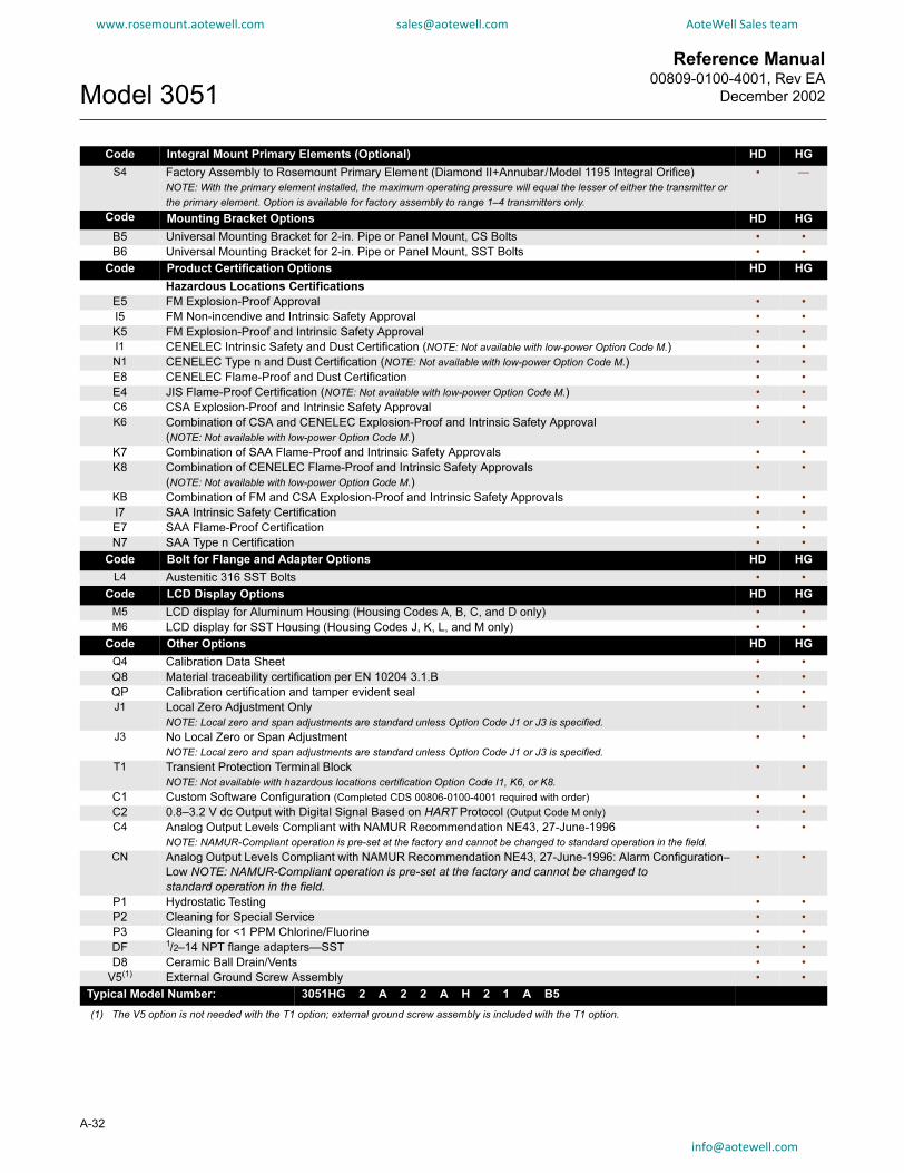
Reference Manual00809-0100-4001, Rev EA
December 2002Model 3051
www.rosemount.aotewell.com [email protected] AoteWell Sales team
Code Integral Mount Primary Elements (Optional) HD HG
S4 Factory Assembly to Rosemount Primary Element (Diamond II+Annubar/Model 1195 Integral Orifice)
NOTE: With the primary element installed, the maximum operating pressure will equal the lesser of either the transmitter or
the primary element. Option is available for factory assembly to range 1–4 transmitters only.
• —
Code Mounting Bracket Options HD HG
B5 Universal Mounting Bracket for 2-in. Pipe or Panel Mount, CS Bolts • •
B6 Universal Mounting Bracket for 2-in. Pipe or Panel Mount, SST Bolts • •
Code Product Certification Options HD HG
Hazardous Locations Certifications
E5 FM Explosion-Proof Approval • •
I5 FM Non-incendive and Intrinsic Safety Approval • •
K5 FM Explosion-Proof and Intrinsic Safety Approval • •
I1 CENELEC Intrinsic Safety and Dust Certification (NOTE: Not available with low-power Option Code M.) • •
N1 CENELEC Type n and Dust Certification (NOTE: Not available with low-power Option Code M.) • •
E8 CENELEC Flame-Proof and Dust Certification • •
E4 JIS Flame-Proof Certification (NOTE: Not available with low-power Option Code M.) • •
C6 CSA Explosion-Proof and Intrinsic Safety Approval • •
K6 Combination of CSA and CENELEC Explosion-Proof and Intrinsic Safety Approval
(NOTE: Not available with low-power Option Code M.)
• •
K7 Combination of SAA Flame-Proof and Intrinsic Safety Approvals • •
K8 Combination of CENELEC Flame-Proof and Intrinsic Safety Approvals
(NOTE: Not available with low-power Option Code M.)
• •
KB Combination of FM and CSA Explosion-Proof and Intrinsic Safety Approvals • •
I7 SAA Intrinsic Safety Certification • •
E7 SAA Flame-Proof Certification • •
N7 SAA Type n Certification • •
Code Bolt for Flange and Adapter Options HD HG
L4 Austenitic 316 SST Bolts • •
Code LCD Display Options HD HG
M5 LCD display for Aluminum Housing (Housing Codes A, B, C, and D only) • •
M6 LCD display for SST Housing (Housing Codes J, K, L, and M only) • •
Code Other Options HD HG
Q4 Calibration Data Sheet • •
Q8 Material traceability certification per EN 10204 3.1.B • •
QP Calibration certification and tamper evident seal • •
J1 Local Zero Adjustment Only
NOTE: Local zero and span adjustments are standard unless Option Code J1 or J3 is specified.
• •
J3 No Local Zero or Span Adjustment
NOTE: Local zero and span adjustments are standard unless Option Code J1 or J3 is specified.
• •
T1 Transient Protection Terminal Block
NOTE: Not available with hazardous locations certification Option Code I1, K6, or K8.
• •
C1 Custom Software Configuration (Completed CDS 00806-0100-4001 required with order) • •
C2 0.8–3.2 V dc Output with Digital Signal Based on HART Protocol (Output Code M only) • •
C4 Analog Output Levels Compliant with NAMUR Recommendation NE43, 27-June-1996
NOTE: NAMUR-Compliant operation is pre-set at the factory and cannot be changed to standard operation in the field.
• •
CN Analog Output Levels Compliant with NAMUR Recommendation NE43, 27-June-1996: Alarm Configuration–
Low NOTE: NAMUR-Compliant operation is pre-set at the factory and cannot be changed to
standard operation in the field.
• •
P1 Hydrostatic Testing • •
P2 Cleaning for Special Service • •
P3 Cleaning for <1 PPM Chlorine/Fluorine • •
DF 1/2–14 NPT flange adapters—SST • •
D8 Ceramic Ball Drain/Vents • •
V5(1) External Ground Screw Assembly • •
Typical Model Number: 3051HG 2 A 2 2 A H 2 1 A B5
(1) The V5 option is not needed with the T1 option; external ground screw assembly is included with the T1 option.
A-32

Reference Manual 00809-0100-4001, Rev EA
December 2002 Model 3051
www.rosemount.aotewell.com [email protected] AoteWell Sales team
Model Transmitter Type (Select One) PD PG
3051PD Model 3051P Reference Class Differential Pressure Transmitter • —
3051PG Model 3051 P Reference Class Gage Pressure Transmitter
Pressure Ranges (Range/Min. Span)
Code Model 3051 PD Model 3051 PG
2 –250 to 250 inH2O/25 inH2O
(–0,62 to 0,62 bar/62,3 mbar)
–250 to 250 inH2O/25 inH2O
(–0,62 to 0,62 bar/6,2 mbar)
• •
3 –1000 to 1000 inH2O/100 inH2O
(–2,5 to 2,5 bar/25 mbar)
–407 to 100 inH2O/100 in H2O
(–1,01 to 2,5 bar/250 mbar)
• •
4 Not Applicable –14.7 to 30 psi/30 psi
(–1,01 to 20,7 bar/207 mbar)
— •
5 Not Applicable –14.7 to 200 psig/200 psi
(–1,01 to 138 bar/1,4 bar)
— •
NOTE: 3051PG lower range limit varies with atmospheric pressure.
Code Output PD PG
A 4–20 mA with Digital Signal Based on HART Protocol • •
Code
MATERIALS OF CONSTRUCTION
PD PGProcess Flange Type Flange Material Drain/Vent
2 Coplanar SST SST • •
0(1) Alternate Flange—See Alternate Flange Options page A-33. • •
Code Isolating Diaphragm PD PG
2 316L SST • •
Code O-ring Material PD PG
A Glass-Filled TFE • •
Code Fill Fluid PD PG
1 Silicone • •
2 Inert (Halocarbon) • •
Code Housing Material Conduit Entry Size PD PG
A Polyurethane-covered Aluminum ½–14 NPT • •
B Polyurethane-covered Aluminum M20 × 1.5 (CM20) • •
C Polyurethane-covered Aluminum PG 13.5 • •
D Polyurethane-covered Aluminum G½ • •
J SST ½–14 NPT • •
K SST M20 × 1.5 (CM20) • •
L SST PG 13.5 • •
M SST G½ • •
Code Alternate Flange Options (Requires Materials of Construction Code 0) PD PG
H2 Traditional Flange, 316 SST Drain/Vent, SST Flange Adapter • •
FA Level Flange, SST, 2 in., ANSI Class 150, Vertical Mount • •
FB Level Flange, SST, 2 in., ANSI Class 300, Vertical Mount • •
FC Level Flange, SST, 3 in., ANSI Class 150, Vertical Mount • •
FD Level Flange, SST, 3 in., ANSI Class 300, Vertical Mount • •
FP DIN Level Flange, SST, DN 50, PN 40, Vertical Mount
FQ DIN Level Flange, SST, DN 80, PN 40, Vertical Mount
Code Integral Mount Manifold Options PD PG
S5 Assemble to Model 305 Integral Manifold • •
Code Integral Mount Primary Elements (Optional) PD PG
S4 Factory Assembly to Rosemount Primary Element (Diamond II+Annubar/Model 1195 Integral Orifice)
NOTE: With the primary element installed, the maximum operating pressure will equal the lesser of either the
transmitter or the primary element. Option is available for factory assembly to range 2–3 transmitters only.
• —
Continued on next page
A-33

Reference Manual00809-0100-4001, Rev EA
December 2002Model 3051
www.rosemount.aotewell.com [email protected] AoteWell Sales team
Code Mounting Bracket Options PD PG
B4 Coplanar Flange Bracket for 2-in. Pipe or Panel Mounting, All SST • •
B1 Traditional Flange Bracket for 2-in. Pipe Mounting, CS Bolts • •
B2 Traditional Flange Bracket for Panel Mounting, CS Bolts • •
B7 B1 Bracket with Series 300 SST Bolts • •
B8 B2 Bracket with Series 300 SST Bolts • •
BA SST B1 Bracket with Series 300 SST Bolts • •
BC SST B3 Bracket with Series 300 SST Bolts • •
Code Product Certification Options
Hazardous Locations Certifications
E5 FM Explosion-Proof Approval • •
I5 FM Non-incendive and Intrinsic Safety Approval • •
K5 FM Explosion-Proof and Intrinsic Safety Approval • •
I1 CENELEC Intrinsic Safety and Dust Certification • •
N1 CENELEC Type n and Dust Certification • •
E8 CENELEC Flame-Proof and Dust Certification • •
E4 JIS Flame-Proof Certification • •
C6 Canadian Standards Association (CSA) Explosion-Proof and Intrinsic Safety Approval • •
K6 Combination of CSA and CENELEC Explosion-Proof and Intrinsic Safety Approval • •
K7 Combination of SAA Flame-Proof and Intrinsic Safety Approvals • •
K8 Combination of CENELEC Flame-Proof and Intrinsic Safety Approvals • •
KB Combination of FM and CSA Explosion-Proof and Intrinsic Safety Approvals • •
I7 SAA Intrinsic Safety Certification • •
E7 SAA Flame-Proof Certification • •
N7 SAA Type n Certification • •
Code Other Options
Q4 Calibration Data Sheet •
Q8 Material Traceability Certification per EN 10204 3.1.B
NOTE: This option is available for the sensor module housing and
Coplanar or traditional flanges and adapters.
• •
QP Calibration Certification and Tamper Evident Seal • •
L4 Austenitic 316 SST Bolts • •
L5 ANSI/ASTM-A-193-B7M Bolts • •
L6 Monel Bolts • •
M5 LCD display for Aluminum Housing (Housing Codes A, B, C, and D only) • •
M6 LCD display for SST Housing (Housing Codes J, K, L, and M only) • •
J1 Local Zero Adjustment Only
NOTE: Local zero and span adjustments are standard unless Option Code J1 or J3 is specified.
• •
J3 No Local Zero or Span Adjustment
NOTE: Local zero and span adjustments are standard unless Option Code J1 or J3 is specified.
• •
T1 Transient Protection Terminal Block
NOTE: Not available with hazardous locations certification Option Code I1.
• •
C1 Custom Software Configuration (Completed CDS 00806-0100-4001 required with order) • •
C4 Analog Output Levels Compliant with NAMUR Recommendation NE43, 27-June-1996
NOTE: NAMUR-Compliant operation is pre-set at the factory and cannot be changed to standard
operation in the field.
• •
CN Analog Output Levels Compliant with NAMUR Recommendation NE43, 27-June-1996:
Alarm Configuration–Low
NOTE: NAMUR-Compliant operation is pre-set at the factory and cannot be changed to
standard operation in the field.
• •
P1 Hydrostatic Testing • •
P2 Cleaning for Special Service • •
P3 Cleaning for <1 PPM Chlorine/Fluorine • •
P4 Calibrate at line pressure NOTE: Specify Q48 on order for corresponding certificate. • •
DF 1/2–14 NPT flange adapters—SST • •
D7 Coplanar Flange Without Drain/Vent Ports • •
V5(2) External Ground Screw Assembly • •
Typical Model Number: 3051PD 3 A 2 2 A 1 A B4
(1) NOTE: May impact temperature performance under certain conditions. (2) The V5 option is not needed with the T1 option; external ground screw assembly is included with the T1 option.
A-34

Reference Manual 00809-0100-4001, Rev EA
December 2002 Model 3051
www.rosemount.aotewell.com [email protected] AoteWell Sales team
PARTS LIST
Item numbers are references to figure callouts (pages 13–19).Model 3051C Sensor Modules (Min. Span/Range)
Silicone Fill Inert Fill
Part Number Part Number
Note: One spare part is recommended for every 50 transmitters.
Note: Listed by Range and Process Isolator Order Numbers.
–3 to 3/0.1 inH2O, Range 0 (includes Traditional SST flange and SST bolts).
316L SST 03031-1045-0002 03031-1145-0002
–25 to 25 inH2O/0.5 inH2O, Range 1
316L SST 03031-1045-0012 03031-1145-0012
Hastelloy C-276 03031-1045-0013 03031-1145-0013
Monel 03031-1045-0014 03031-1145-0014
Gold-plated Monel 03031-1045-0016 03031-1145-0016
Gold-plated 316 SST 03031-1045-0017 03031-1145-0017
–250 to 250 inH2O/2.5 inH2O, Range 2
316L SST 03031-1045-0022 03031-1145-0022
Hastelloy C-276 03031-1045-0022 03031-1145-0022
Monel 03031-1045-0024 03031-1145-0024
Tantalum 03031-1045-0025 03031-1145-0025
Gold-plated Monel 03031-1045-0026 03031-1145-0026
Gold-plated 316 SST 03031-1045-0027 03031-1145-0027
–1000 to 1000 inH2O/10 inH2O, Range 3
316L SST 03031-1045-0032 03031-1145-0032
Hastelloy C-276 03031-1045-0033 03031-1145-0033
Monel 03031-1045-0034 03031-1145-0034
Tantalum 03031-1045-0035 03031-1145-0035
Gold-plated Monel 03031-1045-0036 03031-1145-0036
Gold-plated 316 SST 03031-1045-0037 03031-1145-0037
–300 to 300 psi/3 psi, Range 4
316L SST 03031-1045-2042 03031-1145-2042
Hastelloy C-276 03031-1045-2043 03031-1145-2043
Monel 03031-1045-2044 03031-1145-2044
Tantalum 03031-1045-2045 03031-1145-2045
Gold-plated Monel 03031-1045-2046 03031-1145-2046
Gold-plated 316 SST 03031-1045-2047 03031-1145-2047
–2000 to 2000/20 psi, Range 5
316L SST 03031-1045-2052 03031-1145-2052
Hastelloy C-276 03031-1045-2053 03031-1145-2053
Monel 03031-1045-2054 03031-1145-2054
Tantalum 03031-1045-2055 03031-1145-2055
Gold-plated Monel 03031-1045-2056 03031-1145-2056
Gold-plated 316 SST 03031-1045-2057 03031-1145-2057
A-35

Reference Manual00809-0100-4001, Rev EA
December 2002Model 3051
A-36
www.rosemount.aotewell.com [email protected] AoteWell Sales team
Model 3051C Gage Modules (Min. Span/Range)
Silicone Fill Inert Fill
Part Number Part Number
Note: One spare part is recommended for every 50 transmitters.
Note: Listed by Range and Process Isolator Order Numbers.
–250 to 250 inH2O/2.5 inH2O, Range 2
316L SST 03031-1045-0022 03031-1145-0022
Hastelloy C-276 03031-1045-0023 03031-1145-0023
Monel 03031-1045-0024 03031-1145-0024
Tantalum 03031-1045-0025 03031-1145-0025
Gold-plated Monel 03031-1045-0026 03031-1145-0026
Gold-plated 316 SST 03031-1045-0027 03031-1145-0027
–335 to 1000 inH2O/10 inH2O, Range 3
316L SST 03031-1045-0032 03031-1145-0032
Hastelloy C-276 03031-1045-0033 03031-1145-0033
Monel 03031-1045-0034 03031-1145-0034
Tantalum 03031-1045-0035 03031-1145-0035
Gold-plated Monel 03031-1045-0036 03031-1145-0036
Gold-plated 316 SST 03031-1045-0037 03031-1145-0037
–12 to 300 psi/3 psi, Range 4
316L SST 03031-1045-1042 03031-1145-1042
Hastelloy C-276 03031-1045-1043 03031-1145-1043
Monel 03031-1045-1044 03031-1145-1044
Tantalum 03031-1045-1045 03031-1145-1045
Gold-plated Monel 03031-1045-1046 03031-1145-1046
Gold-plated 316 SST 03031-1045-1047 03031-1145-1047
–12 to 2000 psi/20 psi, Range 5
316L SST 03031-1045-1052 03031-1145-1052
Hastelloy C-276 03031-1045-1053 03031-1145-1053
Monel 03031-1045-1054 03031-1145-1054
Tantalum 03031-1045-1055 03031-1145-1055
Gold-plated Monel 03031-1045-1056 03031-1145-1056
Gold-plated 316 SST 03031-1045-1057 03031-1145-1057

Reference Manual 00809-0100-4001, Rev EA
December 2002 Model 3051
www.rosemount.aotewell.com [email protected] AoteWell Sales team
Model 3051C Absolute Sensor Modules (Min. Span/Range)
Silicone Fill Inert Fill
Part Number Part Number
Note: One spare part is recommended for every 50 transmitters.
Note: Listed by Range and Process Isolator Order Numbers.
0 to 0.167 psia/5 psia, Range 0 (includes Traditional SST flange and SST bolts).
316L SST 03031-2020-0002 —
Hastelloy C-276 03031-2020-0003 —
Monel 03031-2020-0004 —
Gold-plated Monel 03031-2020-0006 —
Gold-plated 316 SST 03031-2020-0007 —
0 to 30 psia/0.3 psia, Range 1
316L SST 03031-2020-0012 —
Hastelloy C-276 03031-2020-0013 —
Monel 03031-2020-0014 —
Gold-plated Monel 03031-2020-0016 —
Gold-plated 316 SST 03031-2020-0017 —
0 to 150/1.5 psia, Range 2
316L SST 03031-2020-0022 —
Hastelloy C-276 03031-2020-0023 —
Monel 03031-2020-0024 —
Gold-plated Monel 03031-2020-0026 —
Gold-plated 316 SST 03031-2020-0027 —
0 to 800 psia/8 psia, Range 3
316L SST 03031-2020-0032 —
Hastelloy C-276 03031-2020-0033 —
Monel 03031-2020-0034 —
Gold-plated Monel 03031-2020-0036 —
Gold-plated 316 SST 03031-2020-0037 —
Silicone Fill Inert Fill
Model 3051T
Sensor Modules(1)
Isolating
Diaphragm
Housing
Material Part Number Part Number
Gage Sensor Module(2)
0–0.3/30 psig, Range 11/4–18 NPT Female 316L SST Aluminum 03031-3112-3112 03031-3112-11121/4–18 NPT Female Hastelloy C Aluminum 03031-3112-3113 03031-3112-11131/2–14 NPT Female 316L SST Aluminum 03031-3102-3112 03031-3102-11121/2–14 NPT Female Hastelloy C Aluminum 03031-3102-3113 03031-3102-1113
G1/2A DIN 16288 Male 316L SST Aluminum 03031-3132-3112 03031-3132-1112
1/4–18 NPT Female 316L SST SST 03031-3111-3112 03031-3111-11121/4–18 NPT Female Hastelloy C SST 03031-3111-3113 03031-3111-11131/2–14 NPT Female 316L SST SST 03031-3101-3112 03031-3101-11121/2–14 NPT Female Hastelloy C SST 03031-3101-3113 03031-3101-1113
A-37

Reference Manual00809-0100-4001, Rev EA
December 2002Model 3051
www.rosemount.aotewell.com [email protected] AoteWell Sales team
Gage Sensor Module(2) 0–1.5/150 psig, Range 2 1/4–18 NPT Female 316L SST Aluminum 03031-3112-3122 03031-3112-11221/4–18 NPT Female Hastelloy C Aluminum 03031-3112-3123 03031-3112-11231/2–14 NPT Female 316L SST Aluminum 03031-3102-3122 03031-3102-11221/2–14 NPT Female Hastelloy C Aluminum 03031-3102-3123 03031-3102-1123
G1/2A DIN 16288 Male 316L SST Aluminum 03031-3132-3122 03031-3132-1122
1/4–18 NPT Female 316L SST SST 03031-3111-3122 03031-3111-11221/4–18 NPT Female Hastelloy C SST 03031-3111-3123 03031-3111-11231/2–14 NPT Female 316L SST SST 03031-3101-3122 03031-3101-11221/2–14 NPT Female Hastelloy C SST 03031-3101-3123 03031-3101-1123
Gage Sensor Module(2) 0–8/800 psig, Range 31/4–18 NPT Female 316L SST Aluminum 03031-3112-3132 03031-3112-11321/4–18 NPT Female Hastelloy C Aluminum 03031-3112-3133 03031-3112-11331/2–14 NPT Female 316L SST Aluminum 03031-3102-3132 03031-3102-11321/2–14 NPT Female Hastelloy C Aluminum 03031-3102-3133 03031-3102-1133
G1/2A DIN 16288 Male 316L SST Aluminum 03031-3132-3132 03031-3132-1132
1/4–18 NPT Female 316L SST SST 03031-3111-3132 03031-3111-11321/4–18 NPT Female Hastelloy C SST 03031-3111-3133 03031-3111-11331/2–14 NPT Female 316L SST SST 03031-3101-3132 03031-3101-11321/2–14 NPT Female Hastelloy C SST 03031-3101-3133 03031-3101-1133
Gage Sensor Module(2) 0-40/4000 psig, Range 41/4–18 NPT Female 316L SST Aluminum 03031-3112-3142 03031-3112-11421/4–18 NPT Female Hastelloy C Aluminum 03031-3112-3143 03031-3112-11431/2–14 NPT Female 316L SST Aluminum 03031-3102-3142 03031-3102-11421/2–14 NPT Female Hastelloy C Aluminum 03031-3102-3143 03031-3102-1143
G1/2A DIN 16288 Male 316L SST Aluminum 03031-3132-3142 03031-3132-1142
1/4–18 NPT Female 316L SST SST 03031-3111-3142 03031-3111-11421/4–18 NPT Female Hastelloy C SST 03031-3111-3143 03031-3111-11431/2–14 NPT Female 316L SST SST 03031-3101-3142 03031-3101-11421/2–14 NPT Female Hastelloy C SST 03031-3101-3143 03031-3101-1143
Absolute Sensor Module(2) 0–0.3/30 psig, Range 11/4–18 NPT Female 316L SST Aluminum 03031-3112-3012 03031-3112-10121/4–18 NPT Female Hastelloy C Aluminum 03031-3112-3013 03031-3112-10131/2–14 NPT Female 316L SST Aluminum 03031-3102-3012 03031-3102-10121/2–14 NPT Female Hastelloy C Aluminum 03031-3102-3013 03031-3102-1013
G1/2A DIN 16288 Male 316L SST Aluminum 03031-3132-3012 03031-3132-1012
1/4–18 NPT Female 316L SST SST 03031-3111-3012 03031-3111-10121/4–18 NPT Female Hastelloy C SST 03031-3111-3013 03031-3111-10131/2–14 NPT Female 316L SST SST 03031-3101-3012 03031-3101-10121/2–14 NPT Female Hastelloy C SST 03031-3101-3013 03031-3101-1013
Silicone Fill Inert Fill
Model 3051T
Sensor Modules(1)
Isolating
Diaphragm
Housing
Material Part Number Part Number
A-38

Reference Manual 00809-0100-4001, Rev EA
December 2002 Model 3051
www.rosemount.aotewell.com [email protected] AoteWell Sales team
Absolute Sensor Module(2) 0–1.5/150 psig, Range 21/4–18 NPT Female 316L SST Aluminum 03031-3112-3022 03031-3112-10221/4–18 NPT Female Hastelloy C Aluminum 03031-3112-3023 03031-3112-10231/2–14 NPT Female 316L SST Aluminum 03031-3102-3022 03031-3102-10221/2–14 NPT Female Hastelloy C Aluminum 03031-3102-3023 03031-3102-1023
G1/2A DIN 16288 Male 316L SST Aluminum 03031-3132-3022 03031-3132-1022
1/4–18 NPT Female 316L SST SST 03031-3111-3022 03031-3111-10221/4–18 NPT Female Hastelloy C SST 03031-3111-3023 03031-3111-10231/2–14 NPT Female 316L SST SST 03031-3101-3022 03031-3101-10221/2–14 NPT Female Hastelloy C SST 03031-3101-3023 03031-3101-1023
Absolute Sensor Module(2) 0–8/800 psig, Range 31/4–18 NPT Female 316L SST Aluminum 03031-3112-3032 03031-3112-10321/4–18 NPT Female Hastelloy C Aluminum 03031-3112-3033 03031-3112-10331/2–14 NPT Female 316L SST Aluminum 03031-3102-3032 03031-3102-10321/2–14 NPT Female Hastelloy C Aluminum 03031-3102-3033 03031-3102-1033
G1/2A DIN 16288 Male 316L SST Aluminum 03031-3132-3032 03031-3132-1032
1/4–18 NPT Female 316L SST SST 03031-3111-3032 03031-3111-10321/4–18 NPT Female Hastelloy C SST 03031-3111-3033 03031-3111-10331/2–14 NPT Female 316L SST SST 03031-3101-3032 03031-3101-10321/2–14 NPT Female Hastelloy C SST 03031-3101-3033 03031-3101-1033
Absolute Sensor Module(2) 0-40/4000 psig, Range 41/4–18 NPT Female 316L SST Aluminum 03031-3112-3042 03031-3112-10421/4–18 NPT Female Hastelloy C Aluminum 03031-3112-3043 03031-3112-10431/2–14 NPT Female 316L SST Aluminum 03031-3102-3042 03031-3102-10421/2–14 NPT Female Hastelloy C Aluminum 03031-3102-3043 03031-3102-1043
G1/2A DIN 16288 Male 316L SST Aluminum 03031-3132-3042 03031-3132-1042
1/4–18 NPT Female 316L SST SST 03031-3111-3042 03031-3111-10421/4–18 NPT Female Hastelloy C SST 03031-3111-3043 03031-3111-10431/2–14 NPT Female 316L SST SST 03031-3101-3042 03031-3101-10421/2–14 NPT Female Hastelloy C SST 03031-3101-3043 03031-3101-1043
Absolute Sensor Module(2) 0-2000/10000 psig, Range 51/4–18 NPT Female 316L SST Aluminum 03031-3112-3052 03031-3112-10521/4–18 NPT Female Hastelloy C Aluminum 03031-3112-3053 03031-3112-10531/2–14 NPT Female 316L SST Aluminum 03031-3102-3052 03031-3102-10521/2–14 NPT Female Hastelloy C Aluminum 03031-3102-3053 03031-3102-1053
G1/2A DIN 16288 Male 316L SST Aluminum 03031-3122-3052 03031-3122-1052
1/4–18 NPT Female 316L SST SST 03031-3111-3052 03031-3111-10521/4–18 NPT Female Hastelloy C SST 03031-3111-3053 03031-3111-10531/2–14 NPT Female 316L SST SST 03031-3101-3052 03031-3101-10521/2–14 NPT Female Hastelloy C SST 03031-3121-3053 03031-3121-1053
(1) For Model 3051TG Range 5 spare module, order absolute configuration and perform zero trim for gage calibrations.(2) One spare part is recommended for every 50 transmitters.
Silicone Fill Inert Fill
Model 3051T
Sensor Modules(1)
Isolating
Diaphragm
Housing
Material Part Number Part Number
A-39

Reference Manual00809-0100-4001, Rev EA
December 2002Model 3051
A-40
www.rosemount.aotewell.com [email protected] AoteWell Sales team
PART DESCRIPTION PART NUMBER
Electronics Board—Assembly Required CD CG CA L H T
Improved Standard (4–20 mA/HART protocol)(1) 03031-0001-0002 • • • • • •
Improved NAMUR Compliant
(4–20 mA/HART protocol)(1)03031-0001-0003 • • • • • •
Low Power (1–5/0.8–3.2 Volts)(1) 03031-0001-1001 • • • • • •
Electronics Housing, Covers, Terminal Block CD CG CA L H T
NOTE: See drawings below for Previous and Improved Electronics Boards, Housings, and Terminal Blocks. For information on ordering “Previous Design” spare
parts, contact your local Rosemount office. In the U.S., call the Response Center at 1-800-654-7768.
Improved Standard (4–20 mA) Aluminum Housing
Electronics Housing without terminal block
½–14 NPT conduit, Includes RFI Filters 03031-0635-0001 • • • • • •
M20×1.5 (CM20) conduit, Includes RFI filters 03031-0635-0002 • • • • • •
PG 13.5 conduit, Includes RFI Filters 03031-0635-0003 • • • • • •
G½ conduit, Includes RFI Filters 03031-0635-0004 • • • • • •
Electronics Cover (Includes wiring label)(2) 03031-0292-0001 • • • • • •
Standard Terminal Block Assembly(1) 03031-0332-0003 • • • • • •
Transient Terminal Block Assy. (Option T1)(2) 03031-0332-0004 • • • • • •
Local Zero and Span Kit(1) 03031-0293-0002 • • • • • •
External Ground Assembly (Option V5)(1) 03031-0398-0001 • • • • • •
Improved Standard (4–20 mA) 316 SST Housing
Electronics Housing without Terminal Block
½–14 NPT conduit, Includes RFI Filters 03031-0635-0041 • • • • • •
M20×1.5 (CM20) conduit, Includes RFI Filters 03031-0635-0042 • • • • • •
PG 13.5 conduit, Includes RFI Filters 03031-0635-0043 • • • • • •
Electronics Cover (Includes wiring label)(2) 03031-0292-0002 • • • • • •
Standard Terminal Block Assembly(1) 03031-0332-0003 • • • • • •
Transient Terminal Block Assy. (Option T1)(2) 03031-0332-0004 • • • • • •
Local Zero and Span Kit(1) 03031-0293-0002 • • • • • •
External Ground Assembly (Option V5)(1) 03031-0398-0001 • • • • • •
Improved Low Power Aluminum Housing
Electronics Housing without Terminal Block
½–14 NPT conduit, Includes RFI Filters 03031-0635-0101 • • • • • •
Electronics Cover (Includes wiring label)(2) 03031-0292-0001 • • • • • •
Low Power Terminal Block Assembly(1) 03031-0332-1001 • • • • • •
Low Power Transient Terminal Block Assembly (Option T1)(2) 03031-0332-1002 • • • • • •
Local Zero and Span Kit(1) 03031-0293-0002 • • • • • •
External Ground Assembly (Option V5)(1) 03031-0398-0001 • • • • • •
Improved Low Power 316 SST Housing
Electronics Housing without Terminal Block
½–14 NPT conduit, Includes RFI Filters 03031-0635-0141 • • • • • •
Electronics Cover (Includes wiring label)(2) 03031-0292-0002 • • • • • •
Low Power Terminal Block Assembly(1) 03031-0332-1001 • • • • • •
Low Power Transient Terminal Block Assembly (Option T1)(2) 03031-0332-1002 • • • • • •
Local Zero and Span Kit(1) 03031-0293-0002 • • • • • •
External Ground Assembly (Option V5)(1) 03031-0398-0001 • • • • • •

Reference Manual 00809-0100-4001, Rev EA
December 2002 Model 3051
www.rosemount.aotewell.com [email protected] AoteWell Sales team
Flanges CD CG CA L H T
PROCESS FLANGES
Differential Coplanar Flange
Nickel-plated Carbon Steel 03031-0388-0025 • — — — — —
316 SST 03031-0388-0022 • — — — — —
Hastelloy C 03031-0388-0023 • — — — — —
Monel 03031-0388-0024 • — — — — —
Gage/Absolute Coplanar Flange
Nickel-plated Carbon Steel 03031-0388-1025 — • • — — —
316 SST 03031-0388-1022 — • • — — —
Hastelloy C 03031-0388-1023 — • • — — —
Monel 03031-0388-1024 — • • — — —
Coplanar Flange Alignment Screw
(package of 2 screws)
03031-0309-0001 • • • — — —
Traditional Flange
316 SST 03031-0320-0002 • • • — — —
Hastelloy C 03031-0320-0003 • • • — — —
Monel 03031-0320-0004 • • • — — —
Level Flange, Vertical Mount
2 in., Class 150, SST 03031-0393-0221 • • • — — —
2 in., Class 300, SST 03031-0393-0222 • • • — — —
3 in., Class 150, SST 03031-0393-0231 • • • — — —
3 in., Class 300, SST 03031-0393-0232 • • • — — —
DIN, DN 50, PN 40 03031-0393-1002 • • • — — —
DIN, DN 80, PN 40 03031-0393-1012 • • • — — —
Model 3051H Flanges
Process Flange 02051-0072-0002 — — — — • —
Blank Flange (GP Low Side) 02051-0236-0002 — — — — • —
Flange Adapter Union CD CG CA L H T
Nickel-plated Carbon Steel 02024-0069-0005 • • • — — —
316 SST 02024-0069-0002 • • • — — —
Hastelloy C 02024-0069-0003 • • • — — —
Monel 02024-0069-0004 • • • — — —
Drain/Vent Valve Kits CD CG CA L H T
Differential Drain/Vent Kits(1)
316 SST Stem and Seat Kit 01151-0028-0022 • — — — • —
Hastelloy C Stem and Seat Kit 01151-0028-0023 • — — — • —
Monel Stem and Seat Kit 01151-0028-0024 • — — — • —
316 SST Ceramic Ball Drain/Vent Kit 01151-0028-0122 • — — — • —
Hastelloy C Ceramic Ball Drain/Vent Kit 01151-0028-0123 • — — — • —
Monel Ceramic Ball Drain/Vent Kit 01151-0028-0124 • — — — • —
Gage/Absolute Drain/Vent Kits(1)
316 SST Stem and Seat Kit 01151-0028-0012 — • • • • —
Hastelloy C Stem and Seat Kit 01151-0028-0013 — • • • • —
Monel Stem and Seat Kit 01151-0028-0014 — • • • • —
316 SST Ceramic Ball Drain/Vent Kit 01151-0028-0112 — • • • • —
Hastelloy C Ceramic Ball Drain/Vent Kit 01151-0028-0113 — • • • • —
Monel Ceramic Ball Drain/Vent Kit 01151-0028-0114 — • • • • —
(Each kit contains parts for one transmitter.)
A-41

Reference Manual00809-0100-4001, Rev EA
December 2002Model 3051
www.rosemount.aotewell.com [email protected] AoteWell Sales team
O-Ring Packages CD CG CA L H T
Electronic Housing, Cover (Std. and Meter)(1) 03031-0232-0001 • • • • • •
Electronics Housing, Module(1) 03031-0233-0001 • • • • • •
Process Flange, Glass-filled Teflon(1) 03031-0234-0001 • • • — — —
Process Flange, Graphite-filled Teflon 03031-0234-0002 • • • — — —
Flange Adapter, Glass-filled Teflon(1) 03031-0242-0001 • • • — — —
Flange Adapter, Graphite-filled Teflon 03031-0242-0002 • • • — — —
3051H Process Flange, TFE 02051-0167-0001 — — — — • —
Mounting Brackets CD CG CA L H T
Coplanar Flange Bracket Kit
B4 Bracket, SST, 2-in. Pipe Mount, SST Bolts 03031-0189-0003 • • • — — —
3051T Bracket Kit
B4 Bracket, SST, 2-in. Pipe Mount, SST Bolts 02088-0071-0001 — — — — — •
Traditional Flange Bracket Kits
B1 Bracket, 2-in. Pipe Mount, CS Bolts 03031-0313-0001 • • • — — —
B2 Bracket, Panel Mount, CS Bolts 03031-0313-0002 • • • — — —
B3 Flat Bracket for 2-in. Pipe Mount, CS Bolts 03031-0313-0003 • • • — — —
B7 (B1 Style Bracket with SST Bolts) 03031-0313-0007 • • • — — —
B8 (B2 Style Bracket with SST Bolts) 03031-0313-0008 • • • — — —
B9 (B3 Style Bracket with SST Bolts) 03031-0313-0009 • • • — — —
BA (SST B1 Bracket with SST Bolts) 03031-0313-0011 • • • — — —
BC (SST B3 Bracket with SST Bolts) 03031-0313-0013 • • • — — —
Model 3051H Bracket Kits
B5 Universal Bracket for
2-in. Pipe and Panel Mount, CS Bolts
03051-1081-0001 — — — — • —
B6 Universal Bracket for
2-in. Pipe or Panel Mount, SST Bolts
03051-1081-0002 — — — — • —
A-42

Reference Manual 00809-0100-4001, Rev EA
December 2002 Model 3051
www.rosemount.aotewell.com [email protected] AoteWell Sales team
Bolt Kits CD CG CA L H T
Coplanar Flange
Flange Bolt Kit 44 mm (1.75 in.)
Carbon Steel (set of 4) 03031-0312-0001 • • • — — —
316 SST (set of 4) 03031-0312-0002 • • • — — —
ANSI/ASTM-A-193-B7M 03031-0312-0003 • • • — — —
Monel 03031-0312-0004 • • • — — —
Flange/Adapter Bolt Kit 73 mm (2.88 in.)
Carbon Steel (set of 4) 03031-0306-0001 • • • — — —
316 SST (set of 4) 03031-0306-0002 • • • — — —
ANSI/ASTM-A-193-B7M 03031-0306-0003 • • • — — —
Monel 03031-0306-0004 • • • — — —
Manifold/Flange Kit 57 mm (2.25 in.)
Carbon Steel (set of 4) 03031-0311-0001 • — — — — —
316 SST (set of 4) 03031-0311-0002 • — — — — —
ANSI/ASTM-A-193-B7M 03031-0311-0003 • — — — — —
Monel 03031-0311-0004 • — — — — —
Traditional Flange
Differential Flange and Adapter Bolt Kit
44 mm (1.75 in.)
Carbon Steel (set of 8) 03031-0307-0001 • — — — — —
316 SST (set of 8) 03031-0307-0002 • — — — — —
ANSI/ASTM-A-193-B7M 03031-0307-0003 • — — — — —
Monel 03031-0307-0004 • — — — — —
Gage/Absolute Flange and Adapter Bolt Kit
Carbon Steel (set of 6) 03031-0307-1001 — • • — — —
316 SST (set of 6) 03031-0307-1002 — • • — — —
ANSI/ASTM-A-193-B7M 03031-0307-1003 — • • — — —
Monel 03031-0307-1004 — • • — — —
Manifold/Traditional Flange Bolts
Carbon Steel Use bolts supplied with manifold
316 SST Use bolts supplied with manifold
Level Flange, Vertical Mount
Flange Bolt Kit
Carbon Steel (set of 4) 03031-0395-0001 • • • — — —
316 SST (set of 4) 03031-0395-0002 • • • — — —
(Each kit contains bolts for one transmitter.)
Model 3051H Flange
Process Flange Bolt Kit, Carbon Steel 02051-0164-0001 — — — — • —
FlangeBolt (set of 4)
Flange Nut (set of 4)
Adapter Bolts (set of 4)
Other
Process Flange Bolt Kit, 316 SST 02051-0164-0002 — — — — • —
Bolt for Process Flange (set of 4)
Nut for Process Flange (set of 4)
Adapter Bolts (set of 4)
(1) One spare part is recommended for every 25 transmitters.(2) One spare part is recommended for every 50 transmitters
A-43

Reference Manual00809-0100-4001, Rev EA
December 2002Model 3051
www.rosemount.aotewell.com [email protected] AoteWell Sales team
Part Description Part Number
Meter for current Aluminum Housing CD CG CA L H T
Meter Kit 03031-0193-0101 • • • • • •
Meter Display
Captive Mounting Hardware
10-pin Interconnection Header
Cover Assembly
Meter Hardware Only 03031-0193-0103 • • • • • •
Meter Display
Captive Mounting Hardware
10-pin Interconnection Header
Cover Assembly Kit 03031-0193-0002 • • • • • •
Meter for current 316 SST Housing CD CG CA L H T
Meter Kit (1) 03031-0193-0111 • • • • • •
Meter Display
Captive Mounting Hardware
10-pin Interconnection Header
Cover Assembly
Meter Hardware Only 03031-0193-0103 • • • • • •
Meter Display
Captive Mounting Hardware
10-pin Interconnection Header
Cover Assembly Kit 03031-0193-0012 • • • • • •
Meter for Previous Aluminum Housing CD CG CA L H T
Previous Meter Kit (1) 03031-0193-0001 • • • • • •
NOTE: Previous Meter Kit includes meter display, captive mounting hardware, 6-pin interconnection header, and cover assembly.
Improved Kit for Previous Aluminum Housing (1) 03031-0193-1101 • • • • • •
Meter Display
Captive Mounting Hardware
10-pin Interconnection Header
Cover Assembly
Previous Meter Hardware Only (1) 03031-0193-0003 • • • • • •
NOTE: Previous Meter Hardware includes meter display, captive mounting hardware, and 6-pin interconnection header only.
Improved Meter for Previous Housing 03031-0193-1103 • • • • • •
Meter Display
Captive Mounting Hardware
10-pin Interconnection Header
Cover Assembly Kit 03031-0193-0002 • • • • • •
Meter for Previous 316 SST Housing CD CG CA L H T
Previous Meter Kit (1) 03031-0193-0011 • • • • • •
Improved Kit for Previous SST Housing (1) 03031-0193-1111 • • • • • •
Meter Display
Captive Mounting Hardware
10-pin Interconnection Header
Cover Assembly
Previous Meter Hardware Only (1) 03031-0193-0003 • • • • • •
Improved Meter for Previous Housing (1) 03031-0193-1103 • • • • • •
Meter Display
Captive Mounting Hardware
10-pin Interconnection Header
Cover Assembly Kit 03031-0193-0012 • • • • • •
A-44

Reference Manual 00809-0100-4001, Rev EA
December 2002 Model 3051
www.rosemount.aotewell.com [email protected] AoteWell Sales team
OPTIONS
Standard Configuration
Unless otherwise specified, transmitter is shipped as follows:Custom Configuration HART protocol only (Option Code C1)
If Option Code C1 is ordered, the customer may specify the following data in addition to the standard configuration parameters.
• Output Information
• Transmitter Information
• LCD Dispaly Configuration
• Hardware Selectable Information
• Signal Selection
Refer to the “HART Protocol C1 Option Configuration Data Sheet” on page 50.
Tagging
Three customer tagging options are available:
1. Standard SST hardware tag is wired to the transmitter. Tag character height is 0.125 in. (3,18 mm), 56 characters maximum.
2. Tag may be permanently stamped on transmitter nameplate upon request, 56 characters maximum.
3. Tag may be stored in transmitter memory (30 characters maximum). Software tag is left blank unless specified.
ENGINEERING UNITSDifferential/Gage:
Absolute/3051T:
inH2O (Range 0, 1, 2, and 3) psi (Range 4 and 5)
psi (all ranges)
4 mA (1 V dc): 0 (engineering units above)
20 mA (5 V dc): Upper range limit
Output: Linear
Flange type: Specified model code option
Flange material: Specified model code option
O-ring material: Specified model code option
Drain/vent: Specified model code option
Integral meter: Installed or none
Alarm: Upscale
Software tag: (Blank)
A-45

Reference Manual00809-0100-4001, Rev EA
December 2002Model 3051
A-46
www.rosemount.aotewell.com [email protected] AoteWell Sales team
Optional Model 305 or Model 306 Integral Manifolds
Factory assembled to Model 3051C and Model 3051T transmitters. Refer to the following Rosemount document for more information: Product Data Sheet 00813-0100-4733
Optional Three-Valve Manifolds (Packaged Separately)
Part No.1151-0150-0001
3-Valve Manifold, Carbon Steel
Part No. 1151-0150-0002
3-Valve Manifold, 316 SST
Optional Diaphragm and Sanitary Seals
Refer to Product Data Sheet 00813-0100-4016 or 00813-0201-4016.
Output Information
Output range points must be the same unit of measure. Available units of measure include:
inH2O inH2O@4 °C(1)
(1) Not available on low power or previous versions.
psi Pa
inHg ftH2O bar kPa
mmH2O mmH2O@4 °C(1) mbar torr
mmHg g/cm2 kg/cm2 atm
LCD Display
M5 Digital Meter, 5-Digit, 2-Line LCD• Direct reading of digital data for higher accuracy
• Displays user-defined flow, level, volume, or pressure units
• Displays diagnostic messages for local troubleshooting
• 90-degree rotation capability for easy viewing
M6 Digital Meter with 316 Stainless Steel Cover
• For use with stainless steel housing option (housing codes J, K, and L)
Local Span and Zero Adjustment
Transmitters ship with local span and zero adjustments standard unless otherwise specified.
• Non-interactive external zero and span adjustments ease calibration
• Magnetic switches replace standard potentiometer adjustments to optimize performance
J1 Local Zero Adjustment Only
J3 No Local Zero or Span Adjustment

Reference Manual 00809-0100-4001, Rev EA
December 2002 Model 3051
www.rosemount.aotewell.com [email protected] AoteWell Sales team
Transient Protection
• Integral transient protection terminal block• Meets IEEE Standard 587, Category B1 kV crest (10 1 000 microseconds)3 kV crest (8 20 microseconds)6 kV crest (1.2 50 microseconds)
• Meets IEEE Standard 472,Surge Withstand CapabilitySWC 2,5 kV crest, 1 MHz wave form
• Applicable standards: 61000-4-4, 61000-4-5
T1 Integral Transient Protection Terminal Block
Bolts for Flanges and Adapters
• Options permit bolts for flanges and adapters to be obtained in various materials
• Standard material is plated carbon steel per ASTM A449, Type 1
L4 Austenitic 316 Stainless Steel Bolts
L5 ASTM-A-193-B7M Bolts
L6 Monel Bolts
Model 3051C/P Coplanar Flange and Model 3051T Bracket Option
B4 Bracket for 2-in. Pipe or Panel Mounting
• For use with the standard Coplanarflange configuration
• Bracket for mounting of transmitter on 2-in. pipe or panel
• Stainless steel construction with stainless steel bolts
Model 3051H Bracket Options
B5 Bracket for 2-in. Pipe or Panel Mounting
• For use with the Model 3051H Pressure Transmitter for high process temperatures
• Carbon steel construction with carbonsteel bolts
B6 B5 Bracket with SST Bolts
• Same bracket as the B5 option with Series 300 stainless steel bolts.
A-47

Reference Manual00809-0100-4001, Rev EA
December 2002Model 3051
www.rosemount.aotewell.com [email protected] AoteWell Sales team
Traditional Flange Bracket Options
A-48
B1 Bracket for 2-in. Pipe Mounting
• For use with the traditional flange option
• Bracket for mounting on 2-in. pipe
• Carbon steel construction with carbonsteel bolts
• Coated with polyurethane paint
B2 Bracket for Panel Mounting
• For use with the traditional flange option
• Bracket for mounting transmitter on wallor panel
• Carbon steel construction with carbonsteel bolts
• Coated with polyurethane paint
B3 Flat Bracket for 2-in. Pipe Mounting
• For use with the traditional flange option
• Bracket for vertical mounting of transmitter on 2-in. pipe
• Carbon steel construction with carbonsteel bolts
• Coated with polyurethane paint
B7 B1 Bracket with SST Bolts
• Same bracket as the B1 option with Series 300 stainless steel bolts
B8 B2 Bracket with SST Bolts
• Same bracket as the B2 option with Series 300 stainless steel bolts
B9 B3 Bracket with SST Bolts
• Same bracket as the B3 option with Series 300 stainless steel bolts
BA Stainless Steel B1 Bracket with SST Bolts
• B1 bracket in stainless steel with Series 300 stainless steel bolts
BC Stainless Steel B3 Bracket with SST Bolts
• B3 bracket in stainless steel with Series 300 stainless steel bolts
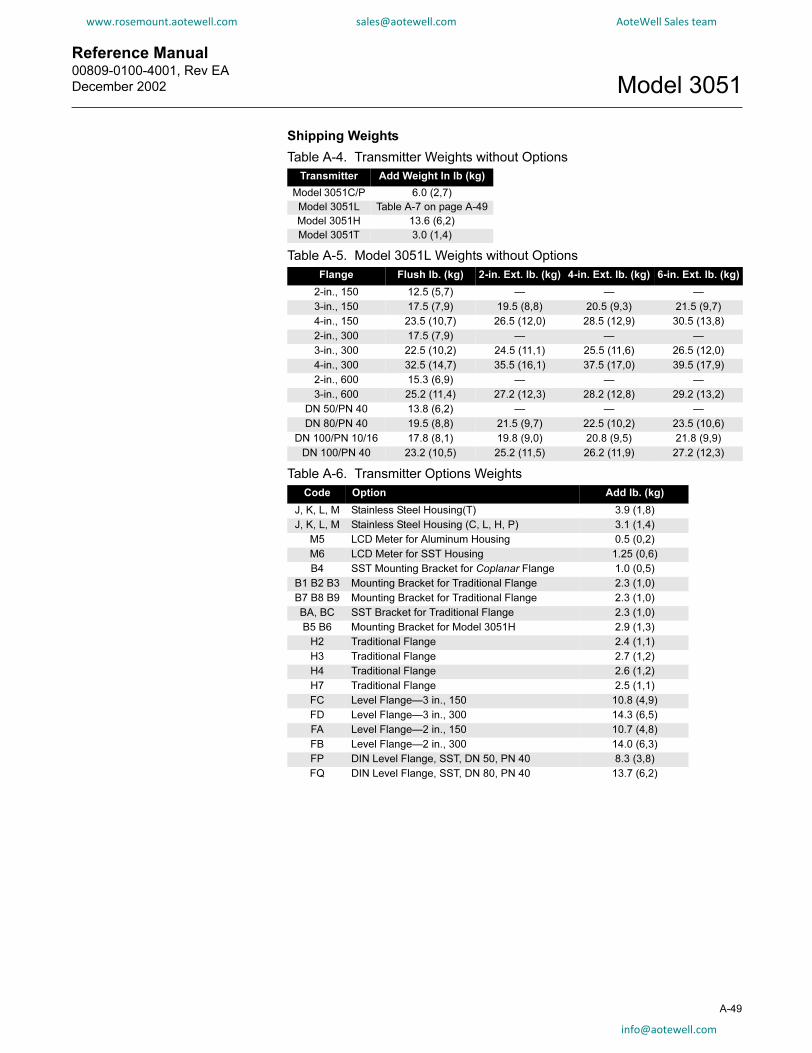
Reference Manual 00809-0100-4001, Rev EA
December 2002 Model 3051
www.rosemount.aotewell.com [email protected] AoteWell Sales team
Shipping Weights
Table A-4. Transmitter Weights without Options
Transmitter Add Weight In lb (kg)
Model 3051C/P 6.0 (2,7)
Model 3051L Table A-7 on page A-49
Model 3051H 13.6 (6,2)
Model 3051T 3.0 (1,4)
Table A-5. Model 3051L Weights without Options
Flange Flush lb. (kg) 2-in. Ext. lb. (kg) 4-in. Ext. lb. (kg) 6-in. Ext. lb. (kg)
2-in., 150 12.5 (5,7) — — —
3-in., 150 17.5 (7,9) 19.5 (8,8) 20.5 (9,3) 21.5 (9,7)
4-in., 150 23.5 (10,7) 26.5 (12,0) 28.5 (12,9) 30.5 (13,8)
2-in., 300 17.5 (7,9) — — —
3-in., 300 22.5 (10,2) 24.5 (11,1) 25.5 (11,6) 26.5 (12,0)
4-in., 300 32.5 (14,7) 35.5 (16,1) 37.5 (17,0) 39.5 (17,9)
2-in., 600 15.3 (6,9) — — —
3-in., 600 25.2 (11,4) 27.2 (12,3) 28.2 (12,8) 29.2 (13,2)
DN 50/PN 40 13.8 (6,2) — — —
DN 80/PN 40 19.5 (8,8) 21.5 (9,7) 22.5 (10,2) 23.5 (10,6)
DN 100/PN 10/16 17.8 (8,1) 19.8 (9,0) 20.8 (9,5) 21.8 (9,9)
DN 100/PN 40 23.2 (10,5) 25.2 (11,5) 26.2 (11,9) 27.2 (12,3)
Table A-6. Transmitter Options Weights
Code Option Add lb. (kg)
J, K, L, M Stainless Steel Housing(T) 3.9 (1,8)
J, K, L, M Stainless Steel Housing (C, L, H, P) 3.1 (1,4)
M5 LCD Meter for Aluminum Housing 0.5 (0,2)
M6 LCD Meter for SST Housing 1.25 (0,6)
B4 SST Mounting Bracket for Coplanar Flange 1.0 (0,5)
B1 B2 B3 Mounting Bracket for Traditional Flange 2.3 (1,0)
B7 B8 B9 Mounting Bracket for Traditional Flange 2.3 (1,0)
BA, BC SST Bracket for Traditional Flange 2.3 (1,0)
B5 B6 Mounting Bracket for Model 3051H 2.9 (1,3)
H2 Traditional Flange 2.4 (1,1)
H3 Traditional Flange 2.7 (1,2)
H4 Traditional Flange 2.6 (1,2)
H7 Traditional Flange 2.5 (1,1)
FC Level Flange—3 in., 150 10.8 (4,9)
FD Level Flange—3 in., 300 14.3 (6,5)
FA Level Flange—2 in., 150 10.7 (4,8)
FB Level Flange—2 in., 300 14.0 (6,3)
FP DIN Level Flange, SST, DN 50, PN 40 8.3 (3,8)
FQ DIN Level Flange, SST, DN 80, PN 40 13.7 (6,2)
A-49

Reference Manual00809-0100-4001, Rev EA
December 2002Model 3051
www.rosemount.aotewell.com [email protected] AoteWell Sales team
HART PROTOCOL C1 OPTION CONFIGURATION DATA SHEET = Default Value(1)
CONFIGURATION DATA SHEET
Customer: _____________________________________________ P.O. No.: _____________________________________________
Model No.: _____________________________________________ Line Item: _____________________________________________
SST Tag No.: _________________________________________________________________________________________________
Software Tag: |__|__|__|__|__|__|__|__|
A-50
OUTPUT INFORMATION: (Software Selectable)
4 mA (1, 0.8 Volts) = ___________________ 0
20 mA (5, 3.2 Volts) = __________________ Upper Range Limit
Pressure Units = inH2O(2) psi (3) Pa ftH2O
inHg bar kPa g/cm2
mbar Torr mmH2O inH2O at 4 °C(5)
Atm kg/cm2 mmHg mmH2O at 4 °C (5)
Output = Linear Square Root (For DP transmitters only)
Damping(4)= 0.00 sec. 0.05 sec. 0.10 sec. 0.20 sec. 0.40 sec.
0.80 sec. 1.60 sec. 3.20 sec. 12.8 sec. 25.6 sec.
(1) Default values may be different outside the U.S. A. Consult your Rosemount Sales Representative for
TRANSMITTER INFORMATION: (Software Selectable)
Descriptor(4): |__|__|__|__|__|__|__|__|__|__|__|__|__|__|__|__|(16 characters)
Message(4): |__|__|__|__|__|__|__|__|__|__|__|__|__|__|__|__|__|__|__|__|__|__|__|__|__|__|__|__|__|__|__|__|
(32 characters)
Date(4): / / Day Month Year
Local Span and Zero: Enabled Disabled
details. (2) inH20 for CD/CG ranges 1-3(3) psi for CD/CG range 4 and 5, all CA ranges(4) C1 option required for configuration of this parameter.(5) Not available with low power output.

Reference Manual
00809-0100-4001, Rev EA
December 2002 Model 3051
www.rosemount.aotewell.com [email protected] AoteWell Sales team
LCD METER CONFIGURATION (Software Adjustable – M5 or M6 option must be specified in model number)
Meter Display Type(4):
Eng. Units only Alternate Eng. Units &% of Range
% of Range only Alternate Eng. Units & Custom Display(5)
Custom Display only Alternate % of Range & Custom Display(5)
Custom Display Configuration: (must be filled out if Custom Display is selected as meter type)
Decimal Point Position
(fixed)—
indicate decimal point location:
X X X
X X
Enter Lower Range Value (Decimal point must be in the same position as specified above.)
(circle sign) + – +000.00
Enter Upper Range Value (Decimal point must be in the same position as specified above.)
(circle sign) + – +100.00
Custom Units—spaces consume A-Z, 0-9, /, *, %, blank
%RNGE
Custom Display Transfer Function (Independent of Analog Output)
Linear Square Root
ATION
HARDWARE SELECTABLE INFORMAlarm Option: High Low
Transmitter Security: Off On
Note: Specify C4 Option in model structure when ordering NAMUR-compliant alarm and saturation limits.(5)
(4) C1 option required for configuration of this parameter.
SIGNAL SELECTION: (Software Selectable)
4–20 mA with simultaneous digital signal based on HART protocol
Burst mode of HART digital process variable (4)
Burst mode output options:
Primary variable in engineering units
Primary variable in percent of range
All dynamic variables in engineering units and the primary variable mA value
Multidrop Communication(4)(6) Choose transmitter address(7) (1-15): _______________
(5) Not available with low power output.(6) This option fixes the transmitter analog output at 4mA.(7) Default address is 1 if multidrop communication is selected.
A-51

Reference Manual00809-0100-4001, Rev EA
December 2002Model 3051
A-52
www.rosemount.aotewell.com [email protected] AoteWell Sales team

Reference Manual 00809-0100-4001, Rev EA
December 2002 Model 3051
www.rosemount.aotewell.com [email protected] AoteWell Sales team
Appendix B Product Certifications
www.rosemount.com
Approved Manufacturing Locations . . . . . . . . . . . . . . . . . . . . . .page B-2
European Directive Information . . . . . . . . . . . . . . . . . . . . . . . . .page B-2
Ordinary Location Certification for Factory Mutual . . . . . . . . .page B-3
Hazardous Locations Certifications . . . . . . . . . . . . . . . . . . . . . .page B-4
Approval Drawings . . . . . . . . . . . . . . . . . . . . . . . . . . . . . . . . . . . .page B-9
OVERVIEW
This Appendix contains information on Approved manufacturing locations, European directive information, Ordinary Location certification, Hazardous Locations Certifications and approval drawings for HART protocol.SAFETY MESSAGES
Procedures and instructions in this section may require special precautions to ensure the safety of the personnel performing the operations. Information that raises potential safety issues is indicated by a warning symbol ( ). Refer to the following safety messages before performing an operation preceded by this symbol.Warnings
Explosions could result in death or serious injury:
Installation of this transmitter in an explosive environment must be in accordance with the
appropriate local, national, and international standards, codes, and practices. Please review
this section of the Model 3051 reference manual for any restrictions associated with a safe
installation.
• Before connecting a HART-based communicator in an explosive atmosphere, make
sure the instruments in the loop are installed in accordance with intrinsically safe or
non-incendive field wiring practices.
• In an Explosion-Proof/Flame-Proof installation, do not remove the transmitter
covers when power is applied to the unit.
Process leaks may cause harm or result in death.
• Install and tighten process connectors before applying pressure.
Electrical shock can result in death or serious injury.
• Avoid contact with the leads and terminals. High voltage that may be present on
leads can cause electrical shock.
Cable gland and plug must comply with the requirements listed on the certificates.
Reference Manual00809-0100-4001, Rev EA
December 2002Model 3051
www.rosemount.aotewell.com [email protected] AoteWell Sales team
APPROVED MANUFACTURING LOCATIONS
B-2
Rosemount Inc. — Chanhassen, Minnesota, USA
Fisher-Rosemount GmbH & Co. — Wessling, Germany
Emerson Process Management Asia Pacific Private Limited — Singapore
EUROPEAN DIRECTIVE INFORMATION
ATEX Directive
Rosemount Inc. complies with the ATEX Directive. Specific ATEX Directive Information is located within Appendix B.Intrinsic safety Ex ia protection type in accordance with EN50 020
• Pressure transmitter with ia type protection shall operate with a certified intrinsic safety power supply only.
• Closing of entries in the device must be carried out using the appropriate EExe or EExn metal cable gland and metal blanking plug or any appropriate ATEX approved cable gland and blanking plug with IP66 rating certified by an EU approved certification body.
• Pressure transmitter with intrinsic safety type protection is not valid if it is not connected to an intrinsic safety circuit.
• The Model 3051 with option code T1(1) does not pass the 500V high voltage test and using it with a shunt-diode safety barrier is not allowed. Transmitter without optioncode T1(1) can be tested using the 500V high voltage test.
Flame-Proof enclosure Ex d protection type in accordance with EN50 018
• Pressure transmitter with flameproof enclosure type protection shall only be opened when power is removed.
• Closing of entries in the device must be carried out using the appropriate EE d metal cable gland and metal blanking plug or any appropriate ATEX approved cable gland and blanking plug with IP66 rating certified by an EU approved certification body.
• Do not exceed the energy level, which is stated on the approval label.
Type n protection type in accordance with EN50 021
• The Model 3051 with option code T1(1) does not pass the 500V high voltage test and using it with a shunt-diode safety barrier is not allowed. Transmitter without optioncode T1(1) can be tested using the 500V high voltage test.
• Closing of entries in the device must be carried out using the appropriate EExe or EExn metal cable gland and metal blanking plug or any appropriate ATEX approved cable gland and blanking plug with IP66 rating certified by an EU approved certification body.
(1) Lightning protection

Reference Manual 00809-0100-4001, Rev EA
December 2002 Model 3051
www.rosemount.aotewell.com [email protected] AoteWell Sales team
European Pressure Equipment Directive (PED) (97/23/EC)
Models 3051CA4; 3051CD2, 3, 4, 5 (also with P9 option); 3051HD2, 3, 4, 5
Pressure Transmitters are category III equipment—
QS Certificate of Assessment - EC No. PED-H-20
All other Model 3051/3001 Pressure Transmitters —
Sound Engineering Practice
Transmitter Attachments: Diaphragm Seal - Process Flange - Manifold —
Sound Engineering Practice
Pressure transmitters that are SEP or Category I with Explosion-Proof protection are outside the scope of PED and cannot be marked for compliance with PED.
Mandatory CE-marking for pressure transmitters in accordance with Article 15 of the PED can be found on the transmitter body (CE 0434).
Pressure transmitters categories I – IV, use module H for conformity assessment procedures.
Electro Magnetic Compatibility (EMC)
Installed signal wiring should not be run together and should not be in the same cable tray as AC power wiring.
Device must be properly grounded or earthed according to local electric codes.
To improve protection against signal interference, shielded cable is recommended, see “Connect Wiring and Power Up” on page 2-16 for more information.
Other important guidelines
Only use new, original parts.
To prevent the process medium escaping, do not unscrew or remove process flange bolts, adapter bolts or bleed screws during operation.
When accessories are added to the transmitter, the minimum pressure rating of any component shall not be exceeded.
Maintenance shall only be done by qualified personnel.
ORDINARY LOCATION CERTIFICATION FOR FACTORY MUTUAL
As standard, the transmitter has been examined, tested, and approved to meet basic electrical, mechanical, and fire protection requirements by FM, a nationally recognized testing laboratory (NRTL) as accredited by the Federal Occupational Safety and Health Administration (OSHA).
B-3

Reference Manual00809-0100-4001, Rev EA
December 2002Model 3051
www.rosemount.aotewell.com [email protected] AoteWell Sales team
HAZARDOUS LOCATIONS CERTIFICATIONS
North American Certifications
B-4
Factory Mutual (FM)
E5 Explosion-Proof for Class I, Division 1, Groups B, C, and D.
Dust-Ignition-Proof for Class II, Division 1, Groups E, F, and G.
Dust-Ignition-Proof for Class III, Division 1.
T5 (Ta = 85 °C), Factory Sealed, Enclosure Type 4x
I5 Intrinsically Safe for use in Class I, Division 1, Groups A, B, C, and D;
Class II, Division 1, Groups E, F, and G; Class III, Division 1 when
connected per Rosemount drawing 03031-1019 and 00268-0031 (When
used with a HART communicator); Non-incendive for Class I, Division 2,
Groups A, B, C, and D.
Temperature Code:T4 (Ta = 40 °C), T3 (Ta = 85 °C),
Enclosure Type 4x
For input parameters see control drawing 03031-1019.
Canadian Standards Association (CSA)
E6 Explosion-Proof for Class I, Division 1, Groups B, C, and D.
Dust-Ignition-Proof for Class II and Class III, Division 1, Groups E, F, and
G. Suitable for Class I, Division 2 Groups A, B, C, and D for indoor and
outdoor hazardous locations. Enclosure type 4X, factory sealed
C6 Explosion-Proof and intrinsically safe approval. Intrinsically safe for Class
I, Division 1, Groups A, B, C, and D when connected in accordance with
Rosemount drawings 03031-1024. Temperature Code T3C.
Explosion-Proof for Class I, Division 1, Groups B, C, and D.
Dust-Ignition-Proof for Class II and Class III, Division 1, Groups E, F, and
G. Suitable for Class I, Division 2 Groups A, B, C, and D hazardous
locations. Enclosure type 4X, factory sealed
For input parameters see control drawing 03031-1024.

Reference Manual 00809-0100-4001, Rev EA
December 2002 Model 3051
www.rosemount.aotewell.com [email protected] AoteWell Sales team
European Certifications
I1 CENELEC Intrinsic Safety and DustCertification No.: BAS 97ATEX1089X II 1 GD
EEx ia IIC T5 (Tamb = –60 to +40 °C)
EEx ia IIC T4 (Tamb = –60 to +70 °C)
Dust Rating: T80 °C (Tamb –20 to 40 °C) IP66
1180
CENELEC I1 Input Parameters
Ui= 30 V
Ii = 200 mA
Pi = 0.9 W
Ci = 0.012 µF
Li = 0.0
Special conditions for Safe Use (X): When the optional transient
protection terminal block is installed, the apparatus is not capable of
withstanding the 500V insulation test required by Clause 6.4.12 of
EN50020:1994. This must be taken into account when installing the
apparatus.
NOTEa) Pressure transmitter with ia type protection shall operate with a certified intrinsic safety power supply only. b) Closing of entries in the device must be carried out using the appropriate EExe or EExn metal cable gland and metal blanking plug or any appropriate ATEX approved cable gland and blanking plug with IP66 rating certified by an EU approved certification body. c) Pressure transmitter with intrinsic safety type protection is not valid if it is not connected to an intrinsic safety circuit.
The transmitter complies with category one (highest category) and is allowed to be installed in ZONE 0.
Figure B-1. Approval Ex label example
3031_A33A
B-5
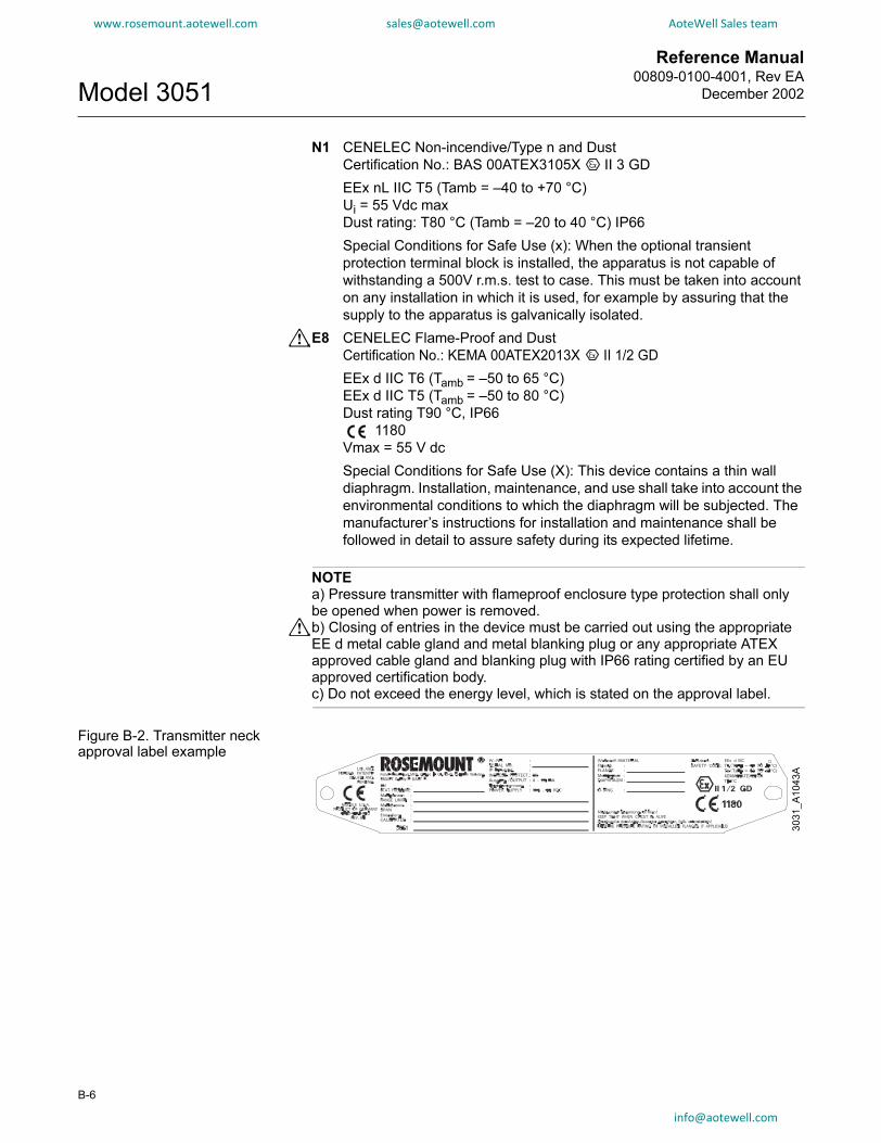
Reference Manual00809-0100-4001, Rev EA
December 2002Model 3051
B-6
www.rosemount.aotewell.com [email protected] AoteWell Sales team
N1 CENELEC Non-incendive/Type n and Dust
Certification No.: BAS 00ATEX3105X II 3 GD
EEx nL IIC T5 (Tamb = –40 to +70 °C)
Ui = 55 Vdc max
Dust rating: T80 °C (Tamb = –20 to 40 °C) IP66
Special Conditions for Safe Use (x): When the optional transient
protection terminal block is installed, the apparatus is not capable of
withstanding a 500V r.m.s. test to case. This must be taken into account
on any installation in which it is used, for example by assuring that the
supply to the apparatus is galvanically isolated.
E8 CENELEC Flame-Proof and Dust
Certification No.: KEMA 00ATEX2013X II 1/2 GD
EEx d IIC T6 (Tamb = –50 to 65 °C)
EEx d IIC T5 (Tamb = –50 to 80 °C)
Dust rating T90 °C, IP66
1180
Vmax = 55 V dc
Special Conditions for Safe Use (X): This device contains a thin wall
diaphragm. Installation, maintenance, and use shall take into account the
environmental conditions to which the diaphragm will be subjected. The
manufacturer’s instructions for installation and maintenance shall be
followed in detail to assure safety during its expected lifetime.
NOTEa) Pressure transmitter with flameproof enclosure type protection shall only be opened when power is removed. b) Closing of entries in the device must be carried out using the appropriate EE d metal cable gland and metal blanking plug or any appropriate ATEX approved cable gland and blanking plug with IP66 rating certified by an EU approved certification body. c) Do not exceed the energy level, which is stated on the approval label.
Figure B-2. Transmitter neck approval label example
3031_A1043A

Reference Manual 00809-0100-4001, Rev EA
December 2002 Model 3051
www.rosemount.aotewell.com [email protected] AoteWell Sales team
Japanese Certifications
E4 JIS Flame-ProofI4 JIS Intrinsic Safety
Certification No.: C13266
Ex ia IIC T4
Certificate
Ex d IIC T5 + G5
Description
C13432 3051C/L/H/P Differential and Gauge (no meter)
C13433 3051C/L/H/P Differential and Gauge (with meter)
C13434 3051CA (no meter)
C13435 3051CA (with meter)
C13436 3051T (no meter)
C13437 3051T (with meter)
Ex d IIC T6
C15151 3051C/D/1 4-20 mA HART (no meter)
C15152 3051C/D/1 4-20 mA HART (with meter)
C15155 3051T/G/1 4-20 mA HART, SST Silicone (no meter)
C15156 3051T/G/1 4-20 mA HART, Hast. Silicone (no meter)
C15157 3051T/G/1 4-20 mA HART, SST Silicone (with meter)
C15158 3051T/G/1 4-20 mA HART, Hast. Silicone (with meter)
Australian Certifications
I7 SAA Intrinsic SafetyCertification No.: AUS EX 1249X
Ex ia IIC T4 (Tamb = 70 °C)
Ex ia IIC T5 (Tamb = 40 °C)
IP65
When connected per Rosemount drawing 03031-1026
Special Conditions for Safe Use (X):
The apparatus may only be used with a passive current limited power
source Intrinsic Safety application. The power source must be such that
Po ≤ (Uo * Io) / 4.
Modules using transient protection in the terminal assembly (T1 transient
protection models) the apparatus enclosure is to be electrically bonded
to the protective earth.
The conductor used for the connection shall be equivalent to a copper
conductor of 4 mm2 minimum cross-sectional area.
SAA Approved Input Parameters
Ui = 30 V
Ii = 200 mA
Ii = 160 mA (Option Code T1)
Pi = 0.9 W
Ci = 0.01 µF (Output Code A)
Ci = 0.042 µF (Output Code M)
Li = 10 µH
Li = 1,05 mH (Output Code A with T1)
Li = 0,75 mH (Output Code M with T1)
B-7

Reference Manual00809-0100-4001, Rev EA
December 2002Model 3051
B-8
www.rosemount.aotewell.com [email protected] AoteWell Sales team
E7 SAA Explosion-Proof (Flame-Proof)
Certification No.: AUS EX 1347X
Ex d IIC T6 (Tamb = 40 °C)
Ex d IIC T5 (Tamb = 80 °C)
DIP T6 (Tamb = 40 °C)
DIP T5 (Tamb = 80 °C)
IP65
Special Conditions for Safe Use (x): It is a condition of safe use for
transmitter enclosures having cable entry thread other than metric
conduit thread that the equipment be utilized with an appropriate certified
thread adaptor.
N7 SAA Type n (Non-sparking)
Certification No.: AUS EX 1249X
Ex n IIC T4 (Tamb = 70 °C)
Ex n IIC T5 (Tamb = 40 °C)
IP65
Special Conditions for Safe Use (x): Where the equipment is installed
such that there is an unused conduit entry, it must be sealed with a
suitable blanking plug to maintain the IP40 degree of protection. Any
blanking plug used with the equipment shall be of a type which requires
the use of a tool to effect its removal. Voltage source shall not exceed
60V ac or 75V dc.
Combinations of Certifications
Stainless steel certification tag is provided when optional approval is specified. Once a device labeled with multiple approval types is installed, it should not be reinstalled using any other approval types. Permanently scratch off or mark unused approval types on the approval label.
K5 E5 and I5 combination
KB K5 and C6 combination
K6 C6, I1, and E8 combination
K8 E8 and I1 combination
K7 E7, I7, and N7 combination

Reference Manual 00809-0100-4001, Rev EA
December 2002 Model 3051
www.rosemount.aotewell.com [email protected] AoteWell Sales team
APPROVAL DRAWINGS
Factory Mutual 03031-1019
1019A01B
B-9

Reference Manual00809-0100-4001, Rev EA
December 2002Model 3051
B-10
www.rosemount.aotewell.com [email protected] AoteWell Sales team
1019A02B

Reference Manual 00809-0100-4001, Rev EA
December 2002 Model 3051
www.rosemount.aotewell.com [email protected] AoteWell Sales team
1019A03B
B-11

Reference Manual00809-0100-4001, Rev EA
December 2002Model 3051
B-12
www.rosemount.aotewell.com [email protected] AoteWell Sales team
1019A04B

Reference Manual 00809-0100-4001, Rev EA
December 2002 Model 3051
www.rosemount.aotewell.com [email protected] AoteWell Sales team
1019A05B
B-13

Reference Manual00809-0100-4001, Rev EA
December 2002Model 3051
B-14
www.rosemount.aotewell.com [email protected] AoteWell Sales team
1019A06B

Reference Manual 00809-0100-4001, Rev EA
December 2002 Model 3051
www.rosemount.aotewell.com [email protected] AoteWell Sales team
1019A07B
B-15

Reference Manual00809-0100-4001, Rev EA
December 2002Model 3051
B-16
www.rosemount.aotewell.com [email protected] AoteWell Sales team
1019A08B

Reference Manual 00809-0100-4001, Rev EA
December 2002 Model 3051
www.rosemount.aotewell.com [email protected] AoteWell Sales team
1019A09B
B-17

Reference Manual00809-0100-4001, Rev EA
December 2002Model 3051
B-18
www.rosemount.aotewell.com [email protected] AoteWell Sales team
1019A010B

Reference Manual 00809-0100-4001, Rev EA
December 2002 Model 3051
www.rosemount.aotewell.com [email protected] AoteWell Sales team
1019A011B
B-19

Reference Manual00809-0100-4001, Rev EA
December 2002Model 3051
B-20
www.rosemount.aotewell.com [email protected] AoteWell Sales team
1019A012B

Reference Manual 00809-0100-4001, Rev EA
December 2002 Model 3051
www.rosemount.aotewell.com [email protected] AoteWell Sales team
Canadian Standards Association (CSA) 03031-1024
1024A01B
B-21

Reference Manual00809-0100-4001, Rev EA
December 2002Model 3051
B-22
www.rosemount.aotewell.com [email protected] AoteWell Sales team
1024A02B

Reference Manual 00809-0100-4001, Rev EA
December 2002 Model 3051
www.rosemount.aotewell.com [email protected] AoteWell Sales team
1024A03B
B-23

Reference Manual00809-0100-4001, Rev EA
December 2002Model 3051
B-24
www.rosemount.aotewell.com [email protected] AoteWell Sales team
1024A04B

Reference Manual 00809-0100-4001, Rev EA
December 2002 Model 3051
www.rosemount.aotewell.com [email protected] AoteWell Sales team
1024A05B
B-25

Reference Manual00809-0100-4001, Rev EA
December 2002Model 3051
B-26
www.rosemount.aotewell.com [email protected] AoteWell Sales team
1024A06B

Reference Manual 00809-0100-4001, Rev EA
December 2002 Model 3051
www.rosemount.aotewell.com [email protected] AoteWell Sales team
1024A07B
B-27

Reference Manual00809-0100-4001, Rev EA
December 2002Model 3051
B-28
www.rosemount.aotewell.com [email protected] AoteWell Sales team
1024A08B

Reference Manual 00809-0100-4001, Rev EA
December 2002 Model 3051
www.rosemount.aotewell.com [email protected] AoteWell Sales team
1024A09B
B-29

Reference Manual00809-0100-4001, Rev EA
December 2002Model 3051
B-30
www.rosemount.aotewell.com [email protected] AoteWell Sales team
Standards Association of Australia (SAA) 03031-1026
1026A01B
m
Reference Manual 00809-0100-4001, Rev EA
December 2002 Model 3051
www.rosemount.aotewell.com [email protected] AoteWell Sales team
1026A02B
B-31

Reference Manual00809-0100-4001, Rev EA
December 2002Model 3051
B-32
www.rosemount.aotewell.com [email protected] AoteWell Sales team
1026A03B

Reference Manual 00809-0100-4001, Rev EA
December 2002 Model 3051
www.rosemount.aotewell.com [email protected] AoteWell Sales team
1026A04B
B-33

Reference Manual00809-0100-4001, Rev EA
December 2002Model 3051
B-34
www.rosemount.aotewell.com [email protected] AoteWell Sales team
0031
A01
A

Reference Manual 00809-0100-4001, Rev EA
December 2002 Model 3051
www.rosemount.aotewell.com [email protected] AoteWell Sales team
B-35
0031
A02
A

Reference Manual00809-0100-4001, Rev EA
December 2002Model 3051
B-36
www.rosemount.aotewell.com [email protected] AoteWell Sales team
0031
A03
A

Reference Manual 00809-0100-4001, Rev EA
December 2002 Model 3051
www.rosemount.aotewell.com [email protected] AoteWell Sales team
B-37
0031
A04
A

Reference Manual00809-0100-4001, Rev EA
December 2002Model 3051
B-38
www.rosemount.aotewell.com [email protected] AoteWell Sales team
0031
A05
A
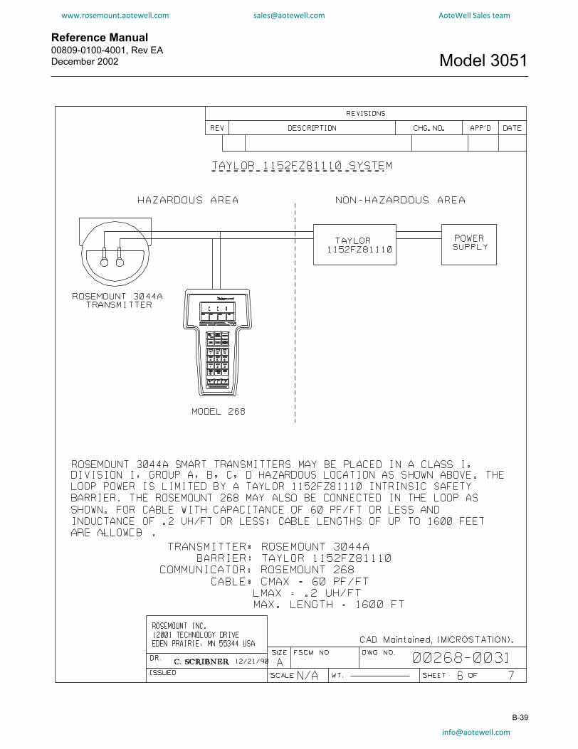
Reference Manual 00809-0100-4001, Rev EA
December 2002 Model 3051
www.rosemount.aotewell.com [email protected] AoteWell Sales team
B-39

Reference Manual00809-0100-4001, Rev EA
December 2002Model 3051
B-40
www.rosemount.aotewell.com [email protected] AoteWell Sales team
0031
A07
A

Reference Manual 00809-0100-4001, Rev EA
December 2002 Model 3051
www.rosemount.aotewell.com [email protected] AoteWell Sales team
Index
AAMS
Commissioning . . . . . . . . . . 3-2ATEX directive . . . . . . . . . . . . . . B-2Accuracy . . . . . . . . . . . . . . . . . . A-2Adapters . . . . . . . . . . . . . . . . . A-47Address
Changing . . . . . . . . . . . . . 3-26Advanced functions
Burst mode . . . . . . . . . . . . 3-24Multidrop communication . 3-25,
3-27Saving, recalling, cloning . . 3-22
Alarm . . . . . . . . . . . . . . . . . . . 3-20Burst mode values . . . . . . . 3-20Configuration procedure . . . 2-14Failure mode . . . . . . . 3-19, A-9Level verification . . . . . . . . 3-20Multidrop mode values . . . . 3-20
Ambient temperature effect . . . . . A-3Analog output
Configure parameters . . . . . 4-3Trim . . . . . . . . . . . . . 4-2, 4-10
Approval
Drawings
Canadian Standards
Association . . B-21Factory Mutual . . . . . . . B-9Standards Association
Australia . . . . B-30Information . . . . . . . . . . . . . B-1
Approval drawings . . . . . . . . . . . B-9Australian certifications . . . . . . . . B-7
BBasic setup . . . . . . . . . . . . . . . . 3-8Bench hook-up . . . . . . . . . . . . . 3-3Block diagram . . . . . . . . . . . . . . 1-3Blowing down . . . . . . . . . . . . . . 2-3Board, electronics . . . . . . . . . . 2-15
www.rosemount.com
Bolts
Adapters . . . . . . . . . . . . . A-47Configurations . . . . . . . . . . 2-8Flanges . . . . . . . . . . . . . . A-47Head markings . . . . . . . . . . 2-7Installation . . . . . . . . . .2-8, 5-8Material . . . . . . . . . . . . . . . 2-8Mounting . . . . . . . . . . . . . . 2-7
Brackets . . . . . . . . . . . . . . . . . . 2-6Options . . . . . . . . . A-47, A-48
Burst mode . . . . . . . . . . . . . . . 3-20Advanced functions . . . . . . 3-24Alarm and saturation values 3-20
Burst pressure limits . . . . . . . . . A-9
CCalibration . . . . . . . . . . . . . . . . 4-2
4-20 mA Output . . . . . . . . . 4-3Frequency,determining . . . . 4-4Overview . . . . . . . . . . . . . . 4-3Sensor . . . . . . . . . . . . . . . . 4-3Sensor trim . . . . . . . . . . . . 4-6Tasks . . . . . . . . . . . . . . . . . 4-2
Canadian Standards Association . B-4Certifications . . . . . . . . . . . . . . . B-1
ATEX directive . . . . . . . . . . B-2Electro magnetic compatibility B-3Hazardous locations
certifications . . . . . . . . . . B-4Ordinary location . . . . . . . . B-3Pressure equipment directive B-3
Check output
Process variables . . . . . . . . 3-7Sensor temperature . . . . . . 3-7
Circuit . . . . . . . . . . . . . . . . . . . 2-6Cloning . . . . . . . . . . . . . . . . . 3-22Commissioning
AMS . . . . . . . . . . . . . . . . . 3-2HART . . . . . . . . . . . . . . . . 3-2
Communication
Multidrop . . . . . . . . .3-25, 3-27Communicator . . . . . . . . .3-4, 4-16Compensating for line pressure 4-12
Configuration . . . . . . . . . . . . . . .3-1Applying a user
configuration . . . . . . . . . .3-23Bolts . . . . . . . . . . . . . . . . . .2-8Cloning . . . . . . . . . . . . . . .3-22Custom . . . . . . . . . . . . . . A-45Data sheet . . . . . . . . . . . . A-50Data, review . . . . . . . . . . . .3-7LCD display . . . . . . . . . . . .3-16
Custom . . . . . . . . . . . .3-17Standard . . . . . . . . . . .3-17
Recalling . . . . . . . . . . . . . .3-22Reusable copy . . . . . . . . . .3-23Saving . . . . . . . . . . . . . . .3-22Standard . . . . . . . . . . . . . A-45
Connections
Electrical . . . . . . . . . . . . . .A-11Considerations
Draft range . . . . . . . . . . . . .2-3Environmental . . . . . . . . . . .2-4General . . . . . . . . . . . . . . . .2-2Mechanical . . . . . . . . . . . . .2-3
Cover installation . . . . . . . . . . . .2-6Curr Fixed . . . . . . . . . . . . . . . .4-15Curr Saturd . . . . . . . . . . . . . . .4-15Custom configuration
LCD display . . . . . . . . . . . .3-17Transmitter . . . . . . . . . . . A-45
DDamping . . . . . . . . 2-3, 3-16, A-10Detailed setup . . . . . . . . 3-19, 4-20Diagnostics . . . . . . . . . . . . . . .3-21
Loop test . . . . . . . . . . . . . .3-21Messages . . . . . . . . 4-14, 4-16
Curr Fixed . . . . . . . . . .4-15Curr Saturd . . . . . . . . .4-15Error . . . . . . . . . . . . . .4-14Fail . . . . . . . . . . . . . . .4-14Fail Config . . . . . . . . .4-15Fail Elect . . . . . . . . . .4-15Fail Module . . . . . . . . .4-14HART Communicator . .4-16Local Dsbld . . . . . . . . .4-16Loop test . . . . . . . . . .4-15Operation . . . . . . . . . .4-16Press Limit . . . . . . . . .4-15

Reference Manual00809-0100-4001, Rev EA
December 2002Model 3051
www.rosemount.aotewell.com [email protected] AoteWell Sales team
Span Fail . . . . . . . . . . 4-16Span Pass . . . . . . . . . 4-16Temp Limit . . . . . . . . . 4-15Warnings . . . . . . . . . . 4-15Write protect . . . . . . . . 4-16Zero Fail . . . . . . . . . . 4-16Zero Pass . . . . . . . . . 4-16
Transmitter test . . . . . . . . . 3-21Diagrams
Bench hook-up . . . . . . . . . . 3-3Field hook-up . . . . . . . . . . . 3-3Low power . . . . . . . . . . . . . 3-3
Digital to analog trim . . . . . . . . . 4-10Dimensional drawings . . . . . . . A-13Disassembly
Before disassembling . . . . . . 5-3Procedures . . . . . . . . . . . . . 5-3Remove electronics board . . 5-4Remove terminal block . . . . . 5-4Remove from service . . . . . . 5-3Sensor module . . . . . . . . . . 5-5
Disassembly procedures . . . . . . . 5-3Draft Range . . . . . . . . . . . . . . . . 2-3Draft range . . . . . . . . . . . . 2-3, A-1
Damping . . . . . . . . . . . . . . . 2-3Installation . . . . . . . . . . . . . 2-3Process noise . . . . . . . . . . . 2-3Side filtering . . . . . . . . . . . . 2-4
Drawings
Approval . . . . . . . . . . . . . . . B-9Canadian Standards
Association . . B-21Factory Mutual . . . . . . . B-9Standards Association
of Australia . . B-30Dimensional . . . . . . . . . . . A-13
Dynamic performance . . . . . . . . A-4
EEMC . . . . . . . . . . . . . . . . . . . . . B-3Earthing . . . . . . . . . . . . . . . . . 2-17Electrical connections . . . . . . . . A-11Electrical considerations
Grounding . . . . . . . . . . . . 2-18Electro magnetic compatibility . . . B-3Electronics board . . . . . . . . . . . 2-15
Installing . . . . . . . . . . . . . . . 5-6Low power . . . . . . . . . . . . 2-16Removing . . . . . . . . . . . . . . 5-4
Environmental considerations . . . 2-4Error . . . . . . . . . . . . . . . . . . . . 4-14European Pressure
Equipment Directive . . . . . . . . . . B-3European certifications . . . . . . . . B-5Exterior . . . . . . . . . . . . . . . . . . . 2-6
Index-2
FFactory Mutual . . . . . . . . . . . . . B-4Fail . . . . . . . . . . . . . . . . . . . . 4-14
Config . . . . . . . . . . . . . . . 4-15Elect . . . . . . . . . . . . . . . . 4-15Module . . . . . . . . . . . . . . 4-14
Failure mode
Alarm values . . . . . . 3-19, A-9Saturation values . . . . . . . 3-19
Fast key sequences . . . . . . . . . . 3-4Features . . . . . . . . . . . . . . . . . . 1-1Field hook-up . . . . . . . . . . . . . . 3-3Filtering
Draft range . . . . . . . . . . . . . 2-4Flange . . . . . . . . . . . . . . . . . . A-47
Orientation . . . . . . . . . . . . . 2-6Foundation fieldbus . . . . . . . . . . 1-2Frequency, determining calibration 4-4Full trim . . . . . . . . . . . . . . .4-6, 4-8Functional specifications . . . . . . A-6
GGrounding . . . . . . . . . . . . . . . 2-18
HHART Communicator
Diagnostics . . . . . . . . . . . 4-16Hazardous locations certifications . . .2-18, B-4
Australian certifications . . . . B-7European certifications . . . . B-5Japanese certifications . . . . B-7North American certifications B-4
High process temperature . . . . . A-2Housing . . . . . . . . . . . . . . . . . . 5-3
Circuit side . . . . . . . . . . . . . 2-6Cover . . . . . . . . . . . . . . . . 2-6Exterior . . . . . . . . . . . . . . . 2-6Remove . . . . . . . . . . . . . . . 5-5Rotation . . . . . . . . . . .2-6, 2-13Terminal side . . . . . . . . . . . 2-6
Humidity limits . . . . . . . . . . . . . A-10
IImpulse piping . . . . . . . . . . . . . 2-12Installation . . . . . . . . . . . . . . . . 2-1
Bolts . . . . . . . . . . . . . .2-8, 5-8Brackets . . . . . . . . . . . . . . 2-6Circuit side . . . . . . . . . . . . . 2-6Cover . . . . . . . . . . . . . . . . 2-6Draft range . . . . . . . . . . . . . 2-3Examples . . . . . . . . . . . . . 2-10Exterior . . . . . . . . . . . . . . . 2-6Flowchart . . . . . . . . . . . . . . 2-5Housing rotation . . . . . . . . . 2-6Integral manifolds . . . . . . . 2-22
LCD display . . . . . . . . . . . .2-19Mechanical considerations . .2-3Model 305 manifold . . . . . .2-22Model 3051 procedures . . . .2-6Mounting . . . . . . . . . . . . . . .2-6Terminal side . . . . . . . . . . . .2-6
Integral manifolds . . . . . . . . . . .2-22Installation . . . . . . . . . . . . .2-22
Introduction . . . . . . . . . . . . . . . .1-1
JJapanese certifications . . . . . . . B-7Jumper
Alarm . . . . . . . . . . . . . . . .2-14Security . . . . . . . . . . . . . . .2-14
KKits . . . . . . . . . . . . . . . . . . . . .2-19
LLCD display . . . . . . . . . .2-15, A-46
Custom configuration . . . . .3-17Installation . . . . . . . . . . . . .2-19Options . . . . . . . . . . . . . . .3-16Standard configuration . . . .3-17
Level verification
Alarm . . . . . . . . . . . . . . . .3-20Limits
Burst pressure . . . . . . . . . . A-9Humidity limits . . . . . . . . . A-10Overpressure . . . . . . . . . . . A-8Range . . . . . . . . . . . . . . . .3-13Range and sensor . . . . . . . A-6Static pressure . . . . . . . . . . A-9Temperature . . . . . . . . . . . A-9
Line pressure
Compensating . . . . . . . . . .4-12Effects . . . . . . . . . . . . . . . A-4
Liquid level . . . . . . . . . . . . . . . . A-2Local Dsbld . . . . . . . . . . . . . . .4-16Local zero and span(local keys)
Control . . . . . . . . . . . . . . .4-20Physical removal . . . . . . . .4-19Software lock out . . . . . . . .4-19
Loop
Setting . . . . . . . . . . . . . . . .3-2Test . . . . . . . . . . . . 3-21, 4-15
Low power
Analog output trim . . . . . . .4-10Diagrams . . . . . . . . . . . . . .3-3Electronics board . . . . . . . .2-16Menu tree . . . . . . . . . . . . . .3-6Output range . . . . . . . 3-9, 4-20

Reference Manual 00809-0100-4001, Rev EA
December 2002 Model 3051
www.rosemount.aotewell.com [email protected] AoteWell Sales team
MMaintenance . . . . . . . . . . . . . . . 4-1Manifolds . . . . . . . . . . . . . . . . 2-22
Installaion . . . . . . . . . . . . . 2-22Manual
Models covered . . . . . . . . . . 1-2Use of . . . . . . . . . . . . . . . . 1-1
Mechanical considerations . . . . . 2-3Menu tree . . . . . . . . . . . . . . . . . 3-5
Low power . . . . . . . . . . . . . 3-6Messages
Diagnostic . . . . . . . . . . . . 4-14Meter, LCD display . . . . . . . . . . 3-17Model 275 HART
Communicator . . . . . . .3-4, 3-5, 3-6Mounting . . . . . . . . . . . . . . . . . . 2-6
Bolts . . . . . . . . . . . . . . . . . 2-7Brackets . . . . . . . . . . . . . . . 2-6Position effects . . . . . . . . . . A-5Requirements . . . . . . . . . . 2-10
Multidrop communication . . . . . 3-27Advanced functions . . . . . . 3-25Mode values . . . . . . . . . . . 3-20Polling . . . . . . . . . . . . . . . 3-27
NNAMUR-compliant values . . . . . 3-19Network
Multidrop . . . . . . . . . . . . . 3-26Noise
Draft range . . . . . . . . . . . . . 2-3Non-wetted parts . . . . . . . . . . . A-12
OOperation . . . . . . . . . . . . 4-1, 4-16
Block diagram . . . . . . . . . . . 1-3Options . . . . . . . . . . . . . . . . . . A-45
Bracket . . . . . . . . . . A-47, A-48LCD display . . . . . . . . . . . 3-16
Ordering Information
Model 3051C . . . . . . . . . . A-21Model 3051H . . . . . . . . . . A-31Model 3051L . . . . . . . . . . . A-27Model 3051P . . . . . . . . . . A-33Model 3051T . . . . . . . . . . . A-25
Ordinary location certification . . . B-3Output
4-20 mA . . . . . . . . . . . . . . . 4-3Low power . . . . . . . . 3-9, 4-20Set . . . . . . . . . . . . . . . . . . . 3-9Square root . . . . . . . . . . . . 3-10
Overpressure limits . . . . . . . . . . A-8
PPED . . . . . . . . . . . . . . . . . . . . . B-3PV Unit . . . . . . . . . . . . . . . . . . 3-8Parameters
Analog output . . . . . . . . . . . 4-3Parts list . . . . . . . . . . . . . . . . . A-35Performance . . . . . . . . . . . . . . . A-4Performance specifications . . . . . A-1
Reference class . . . . . . . . . A-1Physical specifications . . . . . . . A-11Piping, impulse . . . . . . . . . . . . 2-12Polling
Multidrop communication . . 3-27Power supply
4-20 mA transmitters . . . . . 2-17Effect . . . . . . . . . . . . . . . . . A-5Low power . . . . . . . .2-17, 2-18
Power up . . . . . . . . . . . . . . . . 2-16Press Limit . . . . . . . . . . . . . . . 4-15Pressure equipment directive . . . B-3Process
Connections . . . . . . .2-11, A-11Flange . . . . . . . . . . . . . . . . 2-6Wetted parts . . . . . . . . . . . A-11
Model 3051L . . . . . . . A-12Process variables . . . . . . . .3-7, 3-8
Units . . . . . . . . . . . . . . . . . 3-8Product certifications . . . . . . . . . B-1
RRFI effects . . . . . . . . . . . . . . . . A-5Range
Limits . . . . . . . . . . . 3-13, A-6Output . . . . . . . . . . . . . . . . 3-9
Reassembly
Attaching electronics board . 5-6Attaching sensor module . . . 5-5Installing terminal block . . . . 5-6Process sensor body . . . . . . 5-7
Recall factory trim . . . . . . . . . . . 4-9Recalling . . . . . . . . . . . . . . . . 3-22Reference accuracy . . . . . . . . . . A-2Reference class . . . . . . . . . . . . A-1Rerange . . . . . . . . . . . . . .3-10, 4-2
AMS only . . . . . . . . . . . . . 3-13Communicator only . . . . . . 3-10Pressure input source
With AMS . . . . . . . . . 3-13With communicator . . . 3-11With local zero and span . . .
3-11Response Time . . . . . . . . . . . . . A-4Reusable copy . . . . . . . . . . . . 3-23Ribbon cable . . . . . . . . . . . . . . 5-4Rotation
Housing . . . . . . . . . . . . . . . 2-6
SSaturation . . . . . . . . . . . . . . . .3-20
Burst mode values . . . . . . .3-20Failure mode . . . . . . . . . . .3-19Multidrop mode values . . . .3-20
Saving a configuration . . . . . . . .3-22Security . . . . . . . . . . . . . . . . . .2-14Sensor
Calibration . . . . . . . . . . . . . .4-3Limits . . . . . . . . . . . . . . . . A-6Module
Installing . . . . . . . . . . . .5-5Removing . . . . . . . . . . .5-5
Temperature . . . . . . . . 3-7, 3-8Trim . . . . . . . . . . . . . . 4-2, 4-6
Service . . . . . . . . . . . . . .3-21, A-7Service Support . . . . . . . . . . . . .1-1Setting the loop . . . . . . . . . . . . .3-2Setup
Basic . . . . . . . . . . . . . . . . .3-8Detailed . . . . . . . . . 3-19, 4-20
Shipping weights . . . . . .A-12, A-49Signal wiring grounding . . . . . . .2-17Software
Lock out . . . . . . . . . . . . . .2-14Span
Adjustment requirements . . A-7, A-46
Button . . . . . . . . . . . 2-14, 3-12Effect . . . . . . . . . . . . . . . .4-12Fail . . . . . . . . . . . . . . . . . .4-16Pass . . . . . . . . . . . . . . . . .4-16
Spare parts list . . . . . . . . . . . . A-35Specifications
Functional . . . . . . . . . . . . . A-6Burst pressure limit . . . A-9Failure mode alarm . . . A-9Humidity limits . . . . . . A-10Overpressure limits . . . A-8Range and sensor limits A-6Satic pressure limit . . . A-9Service . . . . . . . . . . . . A-7Span adjustment . . . . . A-7Temperature limits . . . . A-9Turn-On time . . . . . . . A-10Volumetric displacement . . .
A-10Zero requrements . . . . A-7
Performance . . . . . . . .A-1, A-4Ambient temperature . . A-3Draft range . . . . . . . . . A-1High process temperature . .
A-2Line pressure effect . . . A-4Liquid level . . . . . . . . . A-2Mounting position effects A-5Power supply effect . . . A-5RFI effect . . . . . . . . . . A-5
Index-3

Reference Manual00809-0100-4001, Rev EA
December 2002Model 3051
www.rosemount.aotewell.com [email protected] AoteWell Sales team
Reference accuracy . . . A-2Reference class . . . . . . A-1Response time . . . . . . . A-4Transient protection . . . . A-5Vibration effect . . . . . . . A-5
Physical . . . . . . . . . . . . . . A-11Electrical connections . A-11Non-wetted parts . . . . A-12Procecss wetted parts . A-11Process connections . . A-11Process-wetted parts . . A-12Shipping weights . . . . . A-12
Square root transition point . . . . 3-10Standard LCD display configuration . .3-17Standard configuration . . . . . . . A-45Static pressure limit . . . . . . . . . . A-9Steam service . . . . . . . . . . . . . . 2-3Support . . . . . . . . . . . . . . . . . . . 1-1
TTagging . . . . . . . . . . . . . . . . . . A-45Temp limit . . . . . . . . . . . . . . . . 4-15Temperature . . . . . . . . . . . . . . . 3-8
Ambient specification . . . . . . A-3High process . . . . . . . . . . . . A-2Limits . . . . . . . . . . . . . . . . . A-9
Terminal block
Installing . . . . . . . . . . . . . . . 5-6Removing . . . . . . . . . . . . . . 5-4
Terminals . . . . . . . . . . . . . . . . . 2-6Test, Transmitter . . . . . . . . . . . 3-21Time
Response . . . . . . . . . . . . . . A-4Turn-on . . . . . . . . . . . . . . A-10
Torque values . . . . . . . . . . . . . . 5-8Transient protection . . . . . A-5, A-47Trim
Analog ouput . . . . . . . . . . . 4-2Analog output . . . . . . . . . . 4-10Choosing a procedure . . . . . 4-6Digital to Analog . . . . . . . . 4-10Full . . . . . . . . . . . . . . 4-6, 4-8Low power analog output . . 4-10Recall factory . . . . . . . . . . . 4-9Sensor . . . . . . . . . . . . 4-2, 4-6Zero . . . . . . . . . . . . . . 4-6, 4-7
Troubleshooting
Reference table . . . . . . . . . . 5-2Turn-On time . . . . . . . . . . . . . . A-10
UUnit
Process variable . . . . . . . . . 3-8
Index-4
VVibration effect . . . . . . . . . . . . . A-5Volumetric displacement . . . . . A-10
WWarnings . . . . . . . . . . . . . . . . 4-15Weights . . . . . . . . . . . . A-12, A-49Wiring
Connect . . . . . . . . . . . . . . 2-16Diagrams
Bench hook-up . . . . . . . 3-3Field hook-up . . . . . . . . 3-3Low power . . . . . . . . . . 3-3
Signal wiring grounding . . . 2-17Write protect . . . . . . . . . .2-14, 4-16
XXmtr Info . . . . . . . . . . . . . . . . 4-16
ZZero
Adjustment requirements . . .A-7, A-46
Button . . . . . . . . . . .2-14, 3-12Effect . . . . . . . . . . . . . . . . 4-12Fail . . . . . . . . . . . . . . . . . 4-16Pass . . . . . . . . . . . . . . . . 4-16Trim . . . . . . . . . . . . . . .4-6, 4-7

Emerson Process Management
© 2002 Rosemount Inc. All rights reserved.
¢00809-0100-4001U¤
Rosemount. the Rosemount logotype, and SCoplanar is a trademark of Rosemount Inc.Hastelloy C and Hastelloy C-276 are registeHalocarbon is a trademark of the HalocarboTeflon is a registered trademark of E.I. du PFluorinert is a registered trademark of MinneMonel is a registered trademark of InternatioSyltherm 800 and D.C. 200 are registered trNeobee M-20 is a registered trademark of PHART is a registered trademark of the HARFoundation fieldbus is a registered trademaAll other marks are the property of their resp
Cover photo: 305-305cover
Rosemount Inc.8200 Market BoulevardChanhassen, MN 55317 USAT (U.S.) 1-800-999-9307T (International) (952) 906-8888F (952) 949-7001
www.rosemount.com
Fisher-RShippingArgelsrie82234 WGermanTel 49 (8Fax 49 (
Reference Manual00809-0100-4001, Rev EA
December 2002Model 3051
www.rosemount.aotewell.com [email protected] AoteWell Sales team
MART FAMILY are registered trademarks of Rosemount Inc.
red trademarks of Cabot Corp.n Products Corporation.ont de Nemours & Co.sota Mining and Manufacturing Company Corporationnal Nickel Co.ademarks of Dow Corning Corporation.VO International, Inc.T Communication Foundation.rk of the Fieldbus Foundation.ective owners.
osemount GmbH & Co. Address:der Feld 3essling
y153) 93908153) 939172
Fisher-Rosemount Singapore Pte Ltd.1 Pandan CrescentSingapore 128461Tel (65) 777-8211Fax (65) 777-0947