Embed Size (px)
Citation preview
MODEL 262 SONIC MAXIMIZERUSER MANUAL
▲
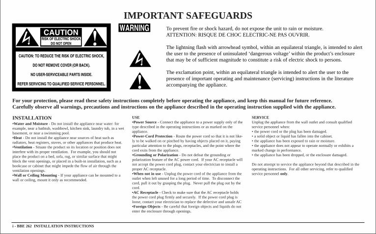
IMPORTANT SAFEGUARDS
For your protection, please read these safety instructions completely before operating the appliance, and keep this manual forfutur e reference.Carefully observe all warnings, precautions and instructions on the appliance described in the operating instruction supplied with the appliance.
i - BBE 262 INSTALLA TION INSTR UCTIONS
INSTALLA TION•Water and Moisture - Do not install the appliance near water: forexample, near a bathtub, washbowl, kitchen sink, laundry tub, in a wetbasement, or near a swimming pool.•Heat - Do not install the appliance near sources of heat such as radiators, heat registers, stoves, or other appliances that produce heat.•Ventilation - Situate the product so its location or position does notinterfere with its proper ventilation. For example, you should notplace the product on a bed, sofa, rug, or similar surface that mightblock the vent openings, or placed in a built-in installation, such as abookcase or cabinet that might impede the flow of air through theventilation openings.•Wall or Ceiling Mounting - If your appliance can be mounted to awall or ceiling, mount it only as recommended.
USE•Power Source - Connect the appliance to a power supply only of thetype described in the operating instructions or as marked on the appliance.•Power-Cord Protection - Route the power cord so that it is not like-ly to be walked on or pinched by having objects placed on it, payingparticular attention to the plugs, receptacles, and the point where thecord exits from the appliance.•Grounding or Polarization - Do not defeat the grounding or polarization feature of the AC power cord. If your AC receptacle willnot accept the power cord plug, contact your electrician to install aproper AC receptacle.•When not in use- Unplug the power cord of the appliance from theoutlet when left unused for a long period of time. To disconnect thecord, pull it out by grasping the plug. Never pull the plug out by thecord.•AC Receptacle- Check to make sure that the AC receptacle holdsthe power cord plug firmly and securely. If the power cord plug isloose, contact your electrician to replace the defective and unsafe AC•Foreign Objects- Be careful that foreign objects and liquids do notenter the enclosure through openings.
SERVICEUnplug the appliance from the wall outlet and consult qualified service personnel when: • the power cord or the plug has been damaged.• a solid object or liquid has fallen into the cabinet.• the appliance has been exposed to rain or moisture.• the appliance does not appear to operate normally or exhibits amarked change in performance.• the appliance has been dropped, or the enclosure damaged.
Do not attempt to service the appliance beyond that described in theoperating instructions. For all other servicing, refer to qualified service personnel only.
To prevent fire or shock hazard, do not expose the unit to rain or moisture.ATTENTION: RISQUE DE CHOC ELECTRIC-NE PAS OUVRIR.
The lightning flash with arrowhead symbol, within an equilateral triangle, is intended to alertthe user to the presence of uninsulated ‘dangerous voltage’within the product’s enclosurethat may be of sufficient magnitude to constitute a risk of electric shock to persons.
The exclamation point, within an equilateral triangle is intended to alert the user to the presence of important operating and maintenance (servicing) instructions in the literatureaccompanying the appliance.
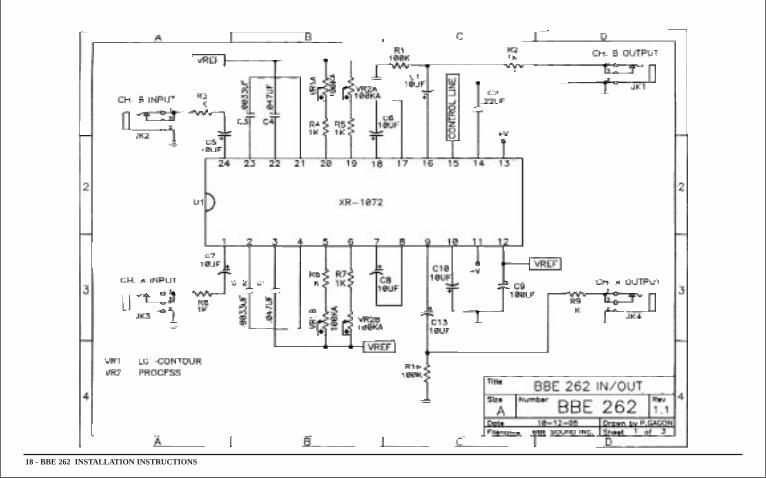
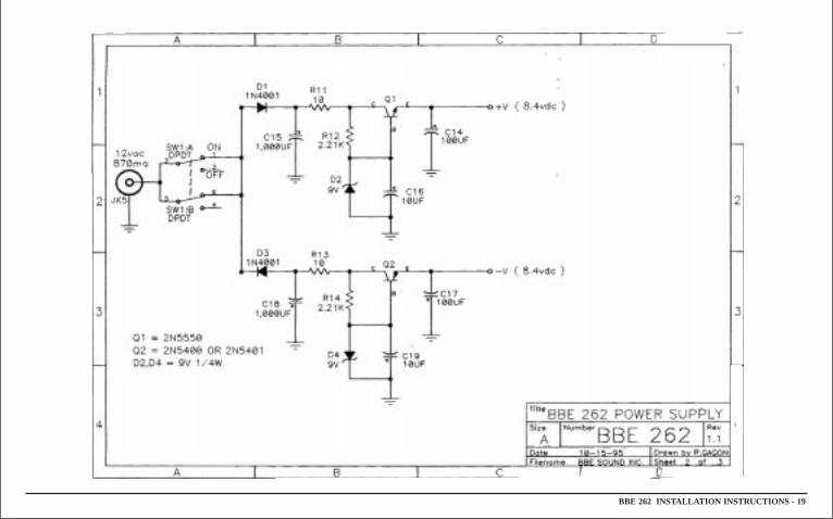
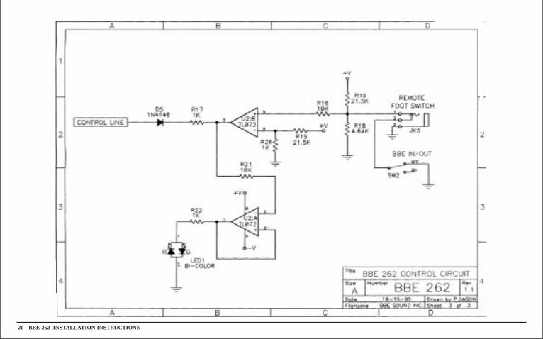
TABLE OF CONTENTSPrecaution . . . . . . . . . . . . . . . . . . . . . . . . . . . . . . . .iProduct Description . . . . . . . . . . . . . . . . . . . . . . . . .2Controls/Connections . . . . . . . . . . . . . . . . . . . . . . . .3General Operation/Applications . . . . . . . . . . . . . . . .5Service/Warranty Information . . . . . . . . . . . . . . . . . .14Test Procedures . . . . . . . . . . . . . . . . . . . . . . . . . . . . .16Specifications . . . . . . . . . . . . . . . . . . . . . . . . . . . . . .17Schematic Diagrams . . . . . . . . . . . . . . . . . . . . . . . . .18
Congratulations on your purchase of the BBE 262 SonicMaximizer, an extremely versatile, two channel signal processorthat will benefit any sound reproduction system. Program material will have sparkle and unmistakable clarity. Lower frequencies, such as a bass guitar, will be more evident in themix. Voices will be crystal clear. Guitar and keyboard noteswill have greater integrity and be more distinct from each other.If classical music is your forte, listen to your favorite symphonyand feel as though you are the conductor. Rap music will takeon new dimensions with a thunderous, yet tight thump whichcannot be achieved with any other sound processor. The BBE262’s flexible design will allow it to be configured into any system. Whether live sound reproduction or in recording studios, the BBE 262 will be a welcome addition.
The following features will make the BBE 262 attractive tosound engineers, players, and listeners:1. Independent PROCESS and LO CONTOUR control for eachchannel to accommodate mono or stereo configurations.2. A FUNCTION switch to allow for the comparison of the BBEprocessed signal to the unprocessed signal.3. A FOOTSWITCH input mono jack for easy connection to anymono shorting footswitch.4. Quarter inch PHONE jacks to allow for easy, unbalanced configuration into any sound system.
IMPORTANTBefore you begin, please check the contents within this box toinsure that included are:1. The BBE 262 Sonic Maximizer.2. 12 volt AC adaptor.3. Four (4) Rubber Feet for ‘Table Mount’applications.4. The BBE 262 User’s Manual.
If any of these items are found to be damaged or missing, immediately contact the BBE dealer from whom the unit was purchased. Before you begin, please read this manual. It willhelp you use the BBE 262 more effectively and answer most of thecommon questions that our service department receives. But if youstill have questions, please call our service department at (714) 897-6766.
BBE 262 INSTALLA TION INSTR UCTIONS - 1
BBE 262 SONIC MAXIMIZERThe BBE Process - ‘What It Is’
Loudspeakers have difficulty dealing with the electronic signals supplied by an amplifier. These difficulties cause such major phase andamplitude distortion that the sound reproduced by a speaker differs significantly from the sound produced by the original source.
In the past, these problems proved unsolvable and were thus delegated to a position of secondary importance in audio system design.However, phase and amplitude integrity is essential to accurate soundreproduction. Research shows that the information which the listenertranslates into the recognizable characteristics of a live performance areintimately tied into complex time and amplitude relationships betweenthe fundamental and harmonic components of a given musical note orsound. These relationships define a sound’s “sound”.
When these complex relationships pass through a speaker, the properorder is lost. The higher frequencies are delayed. A lower frequencymay reach the listener’s ear first or perhaps simultaneously with that ofa higher frequency. In some cases, the components may be sotime-shifted that they reach the listener’s ear ahead of some or all ofthe harmonic components.
This change in the phase and amplitude relationship on the harmonicand fundamental frequencies is technically called ‘envelope distortion.’The listener perceives this loss of sound integrity in the reproducedsound as ‘muddy’and ‘smeared.’In the extreme, it can become diffi -cult to tell the difference between musical instruments, for example, anoboe and a clarinet.
BBE Sound, Inc. conducted extensive studies of numerous speakersystems over a ten year period. With this knowledge, it became
possible to identify the characteristics of an ideal speaker and to distillthe corrections necessary to return the fundamental and harmonic frequency structures to their correct order. While there are differencesamong various speaker designs in the magnitude of their correction, the overall pattern of correction needed isremarkably consistent.
The BBE process is so unique that 42 patents have been awarded bythe U.S. Patent Office.
The BBE Process - ‘How It Works’The BBE Process imparts a pre-determined phase correction to the
high frequencies where most harmonic information exists. This is doneby breaking the signal into three sub-bands or groups: a.) LOs (20Hz -150Hz), b.) MIDs (150Hz - 1200Hz), and c.) HIGHs (1200Hz - 20kHz).
The low group is delayed about 2.5 ms (milliseconds) via a delaywithin the passive low pass filter. The front panel LO CONTOUR control allows for either a flat response or a boost at 50Hz.
The mid-range group is delayed only about 0.5ms and passesthrough an active band-pass filter while the high frequency group is passed through a VCA (Voltage Controlled Amplifier). The highgroup is used as a point of reference to make dynamic amplitude corrections to the high frequencies.
The RMS average loudness detectors continuously monitor both themid-range and high frequencies to compare the relative harmonic content levels of the two bands and apply the appropriateamount of control voltage to the VCA, thereby determining the amountof high frequency harmonic content present at the final output of theBBE processor.
2 - BBE 262 INSTALLA TION INSTR UCTIONS
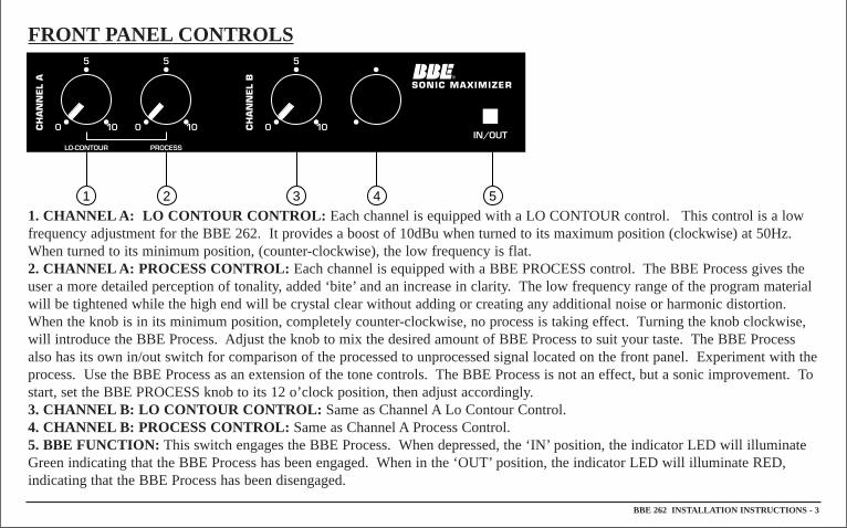
FRONT PANEL CONTROLS
1. CHANNEL A: LO CONT OUR CONTROL: Each channel is equipped with a LO CONTOUR control. This control is a lowfrequency adjustment for the BBE 262. It provides a boost of 10dBu when turned to its maximum position (clockwise) at 50Hz.When turned to its minimum position, (counter-clockwise), the low frequency is flat.2. CHANNEL A: PROCESS CONTROL: Each channel is equipped with a BBE PROCESS control. The BBE Process gives theuser a more detailed perception of tonality, added ‘bite’and an increase in clarity. The low frequency range of the program materialwill be tightened while the high end will be crystal clear without adding or creating any additional noise or harmonic distortion.When the knob is in its minimum position, completely counter-clockwise, no process is taking effect. Turning the knob clockwise,will introduce the BBE Process. Adjust the knob to mix the desired amount of BBE Process to suit your taste. The BBE Processalso has its own in/out switch for comparison of the processed to unprocessed signal located on the front panel. Experiment with theprocess. Use the BBE Process as an extension of the tone controls. The BBE Process is not an effect, but a sonic improvement. Tostart, set the BBE PROCESS knob to its 12 o’clock position, then adjust accordingly.3. CHANNEL B: LO CONT OUR CONTROL: Same as Channel A Lo Contour Control.4. CHANNEL B: PROCESS CONTROL: Same as Channel A Process Control. 5. BBE FUNCTION: This switch engages the BBE Process. When depressed, the ‘IN’position, the indicator LED will illuminateGreen indicating that the BBE Process has been engaged. When in the ‘OUT’position, the indicator LED will illuminate RED,indicating that the BBE Process has been disengaged.
BBE 262 INSTALLA TION INSTR UCTIONS - 3
1 2 3 4 5
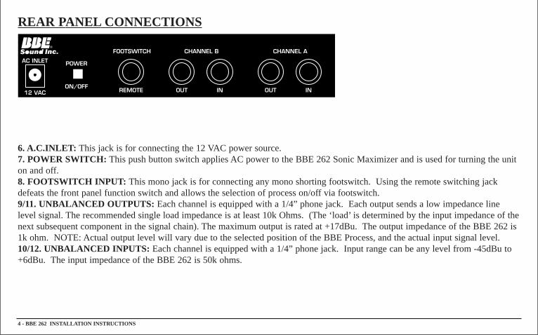
REAR PANEL CONNECTIONS
6. A.C.INLET : This jack is for connecting the 12 VAC power source. 7. POWER SWITCH: This push button switch applies AC power to the BBE 262 Sonic Maximizer and is used for turning the uniton and off. 8. FOOTSWITCH INPUT: This mono jack is for connecting any mono shorting footswitch. Using the remote switching jackdefeats the front panel function switch and allows the selection of process on/off via footswitch. 9/11. UNBALANCED OUTPUTS: Each channel is equipped with a 1/4” phone jack. Each output sends a low impedance linelevel signal. The recommended single load impedance is at least 10k Ohms. (The ‘load’is determined by the input impedance of thenext subsequent component in the signal chain). The maximum output is rated at +17dBu. The output impedance of the BBE 262 is1k ohm. NOTE: Actual output level will vary due to the selected position of the BBE Process, and the actual input signal level.10/12. UNBALANCED INPUTS: Each channel is equipped with a 1/4” phone jack. Input range can be any level from -45dBu to+6dBu. The input impedance of the BBE 262 is 50k ohms.
4 - BBE 262 INSTALLA TION INSTR UCTIONS
GENERAL OPERATION
THE BBE 262 IS A LINE LEVEL SIGNAL PROCESSOR AND IS TO BE CONNECTED PRIOR TO THE POWER AMPIN ANY AUDIO SYSTEM. SIGNIFICANT DAMAGE MA Y BE INFLICTED TO THE BBE 262 OR ANY SUBSEQUENTCOMPONENT IN THE SYSTEM IN THE EVENT THE OUTPUT OF A POWER AMP IS CONNECTED DIRECTL Y TOTHE BBE 262.
In order to reduce the risk of damage to any equipment, properly connect all cables and power cables before turning on any components in the system. Most important of all,ALWAYS TURN ON THE POWER AMPLIFIER LAST TO AVOID DAMAGING THE SPEAKERS OR THE AMP.
The BBE 262 may be utilized in a number of different environments and its results may vary accordingly. Because both channels arecompletely independent from each other, only one channel of the BBE 262 may be used, or each channel processing a different signal source. The effects loop is the ideal placement in the signal chain of a guitar application. In a pre-amp, keyboard or P.A. application, the BBE 262 works best as the last component in the signal chain, just before the crossover or power amp. Impor tant:In a P.A. application, neverconnect the BBE 262 into the effects loop. The inherent phase shift of the BBE Process will causephase cancellation resulting in a partial loss of signal.
BBE 262 INSTALLA TION INSTR UCTIONS - 5
BBE AND EQUALIZA TIONThe most common question asked of the BBE Sound, Inc. service department is: “Where does the BBE Processor connect in the
signal chain, before or after the equalizer?” Many people find that the same amount of equalization is no longer needed, if at all,when a BBE processor is used. Additionally, the amount of equalization used will help determine the BBE 262’s proper location inthe signal chain: If the EQ is being set to give the room a flat response as determined by a spectrum analyzer, the BBE 262 willwork properly before or after the EQ. (Placing the BBE 262 after the EQ is recommended.) If the EQ is being used for drastic tonealteration, the recommended placement would be before the EQ. Neither of these configurations will harm the BBE 262.
When the BBE 262 is being used in a single instrument application, guitar, keyboards, etc., it may be advantageous to experimentwith the proper placement of the BBE in the signal chain. The BBE 262 will improve the sonic quality of the instrument and anyeffects that may be present as well. Important: Generally, reverb and delay do not affect the BBE negatively. However, it is possiblethat with a large amount of effects added to an instrument that the BBE may process irregularly. If this occurs, reconnect the BBE262 as the first item in the processor chain.
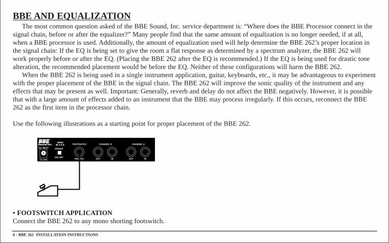
Use the following illustrations as a starting point for proper placement of the BBE 262.
• FOOTSWITCH APPLICA TIONConnect the BBE 262 to any mono shorting footswitch.
6 - BBE 262 INSTALLA TION INSTR UCTIONS
BBE 262 INSTALLA TION INSTR UCTIONS - 7
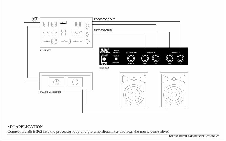
• DJ APPLICA TIONConnect the BBE 262 into the processor loop of a pre-amplifier/mixer and hear the music come alive!
8 - BBE 262 INSTALLA TION INSTR UCTIONS
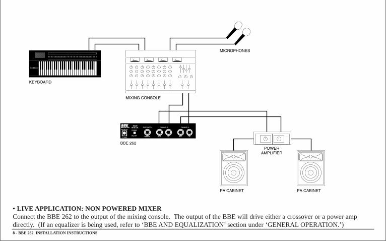
• LIVE APPLICA TION: NON POWERED MIXERConnect the BBE 262 to the output of the mixing console. The output of the BBE will drive either a crossover or a power ampdirectly. (If an equalizer is being used, refer to ‘BBE AND EQUALIZATION’ section under ‘GENERALOPERATION.’)
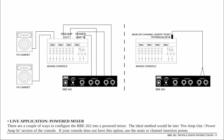
PREAMPOUT
POWERAMP IN
• LIVE APPLICA TION: POWERED MIXERThere are a couple of ways to configure the BBE 262 into a powered mixer. The ideal method would be into ‘Pre-Amp Out / PowerAmp In’ section of the console. If your console does not have this option, use the main or channel insertion points.
BBE 262 INSTALLA TION INSTR UCTIONS - 9
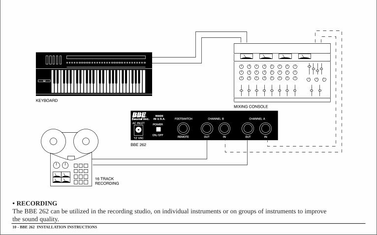
• RECORDINGThe BBE 262 can be utilized in the recording studio, on individual instruments or on groups of instruments to improve the sound quality.10 - BBE 262 INSTALLA TION INSTR UCTIONS
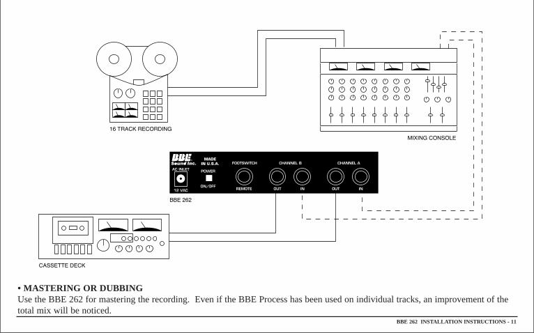
• MASTERING OR DUBBINGUse the BBE 262 for mastering the recording. Even if the BBE Process has been used on individual tracks, an improvement of thetotal mix will be noticed.
BBE 262 INSTALLA TION INSTR UCTIONS - 11
12 - BBE 262 INSTALLA TION INSTR UCTIONS
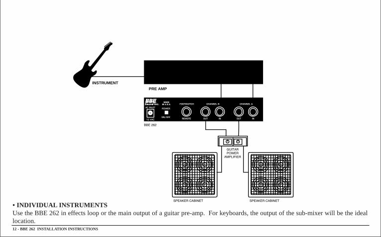
INSTRUMENT
PRE AMP
• INDIVIDUAL INSTRUMENTSUse the BBE 262 in effects loop or the main output of a guitar pre-amp. For keyboards, the output of the sub-mixer will be the ideallocation.
BBE 262 INSTALLA TION INSTR UCTIONS - 13
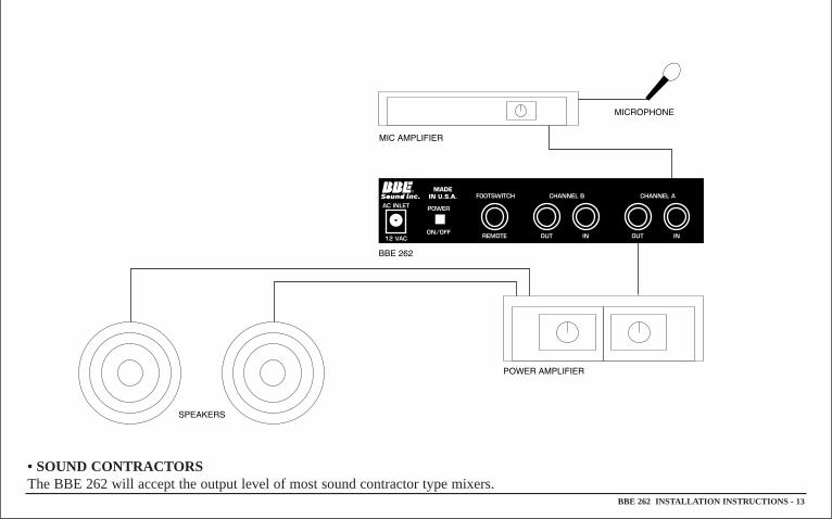
• SOUND CONTRACTORSThe BBE 262 will accept the output level of most sound contractor type mixers.
SERVICE
We recommend that if at all possible a BBE 262 Sonic Maximizer which requires service be sent to our facility in HuntingtonBeach, California. We request that a ‘RETURN AUTHORIZATION’ be issued by the dealer from whom you purchased the unit. Ifthis is not possible, call BBE Sound, Inc. directly at (714) 897-6766, to obtain a ‘RETURN AUTHORIZATION’. Include a copy ofthe bill of sale with the unit when it is shipped to BBE Sound, Inc., so that the service process can be expedited.
As the repair turnaround time is minimal, we request that the unit be sent directly to BBE Sound, Inc. This helps us add reliabilitydata to our files for use in designing future products.
MAINTENANCE
Maintenance of the BBE 262 Sonic Maximizer is limited to proper cleaning of the unit with a mild household cleaner such asFormula 409™ or Windex™. The chassis and cover are steel finished with a durable polyurethane paint, while the front panel is ananodized aluminum extrusion.
There are no user replaceable parts and the unit should not be opened for any reason unless you are a qualified technician.Calibration should be performed if parts are replaced or if a performance check-out indicates a problem with calibration. Long termuse has shown that over the life of the unit there is little or no drift of the components in the BBE 262 which would cause a changein calibration. A conservative design philosophy has resulted in a piece of equipment which should give years of trouble-free service.
14- BBE 262 INSTALLA TION INSTR UCTIONS
BBE 262 INSTALLA TION INSTR UCTIONS - 15
WARRANTYWarranty registration of the unit to BBE Sound Inc. is not necessary. However, it is strongly recommended that a copy of the bill
of sale is retained for future reference.
IT IS THE SOLE RESPONSIBILITY OF THE END USER TO PROVIDE THE BILL OF SALE OR OTHERMEANS OF PROOF OF PURCHASE TO VALIDA TE THE WARRANTY IF WARRANTY SERVICE ISREQUIRED.
The BBE 262 Sonic Maximizer is warranted against defects in material and workmanship for a period of five (5) years from dateof purchase from BBE Sound, Inc. or from an authorized dealer.
During this period, we will repair units free of charge providing that they are shipped prepaid to BBE Sound, Inc., 5381Production Drive, Huntington Beach, CA92649. BBE Sound, Inc. will pay return UPS shipping charges within the USA. All chargesrelated to non-U.S. shipping, including customs clearance, will be billed. The warranty will be honored for the longer of either 90days from the date of any service or the remainder of the original 5 year factory warranty.
The warranty will be considered null and void by BBE Sound, Inc. if any of the following is found:1. The equipment has been physically damaged.2. The equipment shows signs of abuse.3. The equipment has been electrically damaged by improper connection or attempted repair by the customer or a third party.4. The equipment has been modified without authorization.5. The bill of sale indicates that the purchase date of the equipment is not within the warranty period.
All non-warranty repairs are warranted for a period of 90 days from the date of service.
BBE Sound, Inc. is NOTLIABLE FOR CONSEQUENTIALDAMAGES. Should the unit fail to operate for any reason, our soleobligation is to repair the unit as described above.
TEST PROCEDURE FOR THE BBE 262INITIAL UNIT SET UP:Power switch off, BBE switch out, all controls at minimum.
D.C. VOLTAGE TEST:1. With top cover off, connect the 12 volt A. C. power cord to the unit.2. Turn on the power switch of the unit and verify that the front panel L.E.D. is on and ‘Red’in color.3. Measure the D.C. voltage on the positive terminal of capacitor ‘C15’. The voltage should be between +18VDC and+20VDC. 4. Measure the D.C. voltage on the negative terminal of capacitor ‘C18’. The voltage should be between -18VDC and -20VDC.
CHANNEL TEST (SAME FOR BOTH CHANNELS):1. Adjust signal generator for an output of 4 volts peak to peak at 5kHz.2. Connect signal generator to channel A [B] input and observe output with an oscilloscope. Verify that the channel A [B]output is 4volts peak to peak. 3. Turn BBE switch on. Front panel LED should turn ‘Green’. Verify that the channel A[B] output remains at 4 volts peak to peak. 4. Adjust channel A[B] process control to maximum and verify that the channel A[B] output increases to 12 volts peak to peak. 5. Change frequency of signal generator to 500Hz. 6. Verify that the channel A [B] output is 4 volts peak to peak.7. Change frequency of signal generator to 50Hz.8. Adjust channel A[B] lo-contour control to maximum and verify that the channel A[B] output increases 12 volts peak to peak.
***** REPEA T TESTFOR NEXTCHANNEL *****
REMOTE FOOTSWITCH TEST:1. Connect footswitch to remote input jack.2. Verify that pressing the footswitch changes the front panel LED back and forth from ‘Red’to ‘Green’.
16 - BBE 262 INSTALLA TION INSTR UCTIONS
BBE 262 INSTALLA TION INSTR UCTIONS - 17
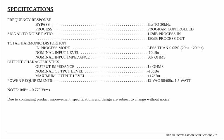
SPECIFICATIONS
FREQUENCYRESPONSEBYPASS . . . . . . . . . . . . . . . . . . . . . . . . . . . . . . . . . . . . . . . . . . . . . . .5hz TO 30kHzPROCESS . . . . . . . . . . . . . . . . . . . . . . . . . . . . . . . . . . . . . . . . . . . . . .PROGRAM CONTROLLED
SIGNAL TO NOISE RATIO . . . . . . . . . . . . . . . . . . . . . . . . . . . . . . . . . . . . . . . . . . . . . .112dB PROCESS IN . . . . . . . . . . . . . . . . . . . . . . . . . . . . . . . . . . . . . . . . . . . . . . . . . . . . . .120dB PROCESS OUT
TOTAL HARMONIC DISTORTIONIN PROCESS MODE . . . . . . . . . . . . . . . . . . . . . . . . . . . . . . . . . . . . .LESS THAN 0.05% (20hz - 20khz)NOMINAL INPUT LEVEL . . . . . . . . . . . . . . . . . . . . . . . . . . . . . . . . .-10dBuNOMINAL INPUT IMPEDANCE . . . . . . . . . . . . . . . . . . . . . . . . . . . .50k OHMS
OUTPUTCHARACTERISTICSOUTPUTIMPEDANCE . . . . . . . . . . . . . . . . . . . . . . . . . . . . . . . . . . .1k OHMSNOMINAL OUTPUTLEVEL . . . . . . . . . . . . . . . . . . . . . . . . . . . . . . .-10dBuMAXIMUM OUTPUT LEVEL . . . . . . . . . . . . . . . . . . . . . . . . . . . . . .+17dBu
POWER REQUIREMENTS . . . . . . . . . . . . . . . . . . . . . . . . . . . . . . . . . . . . . . . . . . . . . .12 VAC 50/60hz 1.5 WATT
NOTE: 0dBu - 0.775 Vrms
Due to continuing product improvement, specifications and design are subject to change without notice.
18 - BBE 262 INSTALLA TION INSTR UCTIONS
BBE 262 INSTALLA TION INSTR UCTIONS - 19
20 - BBE 262 INSTALLA TION INSTR UCTIONS

BBE 262 INSTALLA TION INSTR UCTIONS - 21
NOTES
5381 Production Drive, Huntington Beach, CA 92649Ph: (714) 897-6766 • Fax: (714) 896-0736
Covered by U.S. Patent 4,482,866 and other U.S. and foreign patents pending.BBE is the registered trademark of BBESound, Inc.