Embed Size (px)
Citation preview
iTeledyne Analytical Instruments
Thermal Conductivity Analyzer
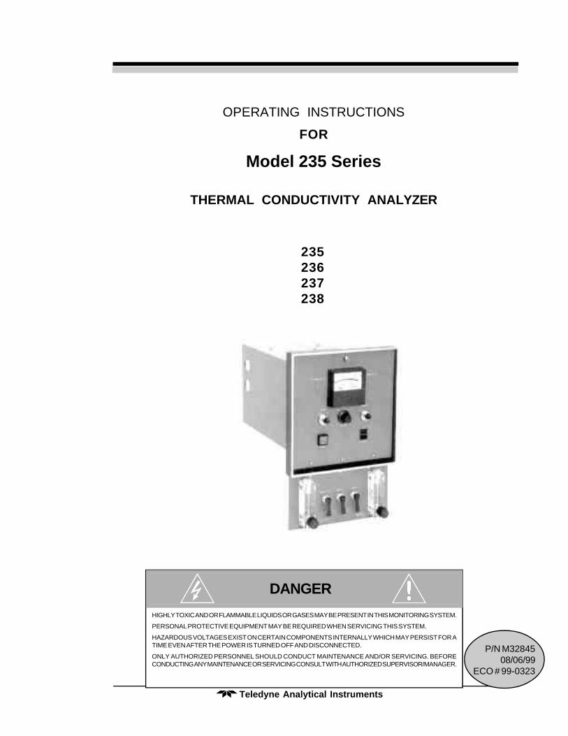
OPERATING INSTRUCTIONS
FOR
Model 235 Series
THERMAL CONDUCTIVITY ANALYZER
235236237238
HIGHLY TOXIC AND OR FLAMMABLE LIQUIDS OR GASES MAY BE PRESENT IN THIS MONITORING SYSTEM.
PERSONAL PROTECTIVE EQUIPMENT MAY BE REQUIRED WHEN SERVICING THIS SYSTEM.
HAZARDOUS VOLTAGES EXIST ON CERTAIN COMPONENTS INTERNALLY WHICH MAY PERSIST FOR ATIME EVEN AFTER THE POWER IS TURNED OFF AND DISCONNECTED.
ONLY AUTHORIZED PERSONNEL SHOULD CONDUCT MAINTENANCE AND/OR SERVICING. BEFORECONDUCTING ANY MAINTENANCE OR SERVICING CONSULT WITH AUTHORIZED SUPERVISOR/MANAGER.
DANGER
P/N M3284508/06/99
ECO # 99-0323
Teledyne Analytical Instrumentsi i
Model 235
Copyright © 1999 Teledyne Analytical Instruments
All Rights Reserved. No part of this manual may be reproduced, transmitted, tran-scribed, stored in a retrieval system, or translated into any other language or computerlanguage in whole or in part, in any form or by any means, whether it be electronic,mechanical, magnetic, optical, manual, or otherwise, without the prior written consent ofTeledyne Analytical Instruments, 16830 Chestnut Street, City of Industry, CA 91749-1580.
Warranty
This equipment is sold subject to the mutual agreement that it is warranted by us freefrom defects of material and of construction, and that our liability shall be limited toreplacing or repairing at our factory (without charge, except for transportation), or atcustomer plant at our option, any material or construction in which defects becomeapparent within one year from the date of shipment, except in cases where quotations oracknowledgements provide for a shorter period. Components manufactured by others bearthe warranty of their manufacturer. This warranty does not cover defects caused by wear,accident, misuse, neglect or repairs other than those performed by Teledyne or an autho-rized service center. We assume no liability for direct or indirect damages of any kind andthe purchaser by the acceptance of the equipment will assume all liability for any damagewhich may result from its use or misuse.
We reserve the right to employ any suitable material in the manufacture of ourapparatus, and to make any alterations in the dimensions, shape or weight of any parts, inso far as such alterations do not adversely affect our warranty.
Important Notice
This instrument provides measurement readings to its user, and serves as a tool bywhich valuable data can be gathered. The information provided by the instrument mayassist the user in eliminating potential hazards caused by his process; however, it isessential that all personnel involved in the use of the instrument or its interface, with theprocess being measured, be properly trained in the process itself, as well as all instrumenta-tion related to it.
The safety of personnel is ultimately the responsibility of those who control processconditions. While this instrument may be able to provide early warning of imminent danger,it has no control over process conditions, and it can be misused. In particular, any alarm orcontrol systems installed must be tested and understood, both as to how they operate andas to how they can be defeated. Any safeguards required such as locks, labels, or redun-dancy, must be provided by the user or specifically requested of Teledyne at the time theorder is placed.
Therefore, the purchaser must be aware of the hazardous process conditions. Thepurchaser is responsible for the training of personnel, for providing hazard warningmethods and instrumentation per the appropriate standards, and for ensuring that hazardwarning devices and instrumentation are maintained and operated properly.
Teledyne Analytical Instruments (TAI), the manufacturer of this instrument,cannot accept responsibility for conditions beyond its knowledge and control. No state-ment expressed or implied by this document or any information disseminated by themanufacturer or its agents, is to be construed as a warranty of adequate safety controlunder the user’s process conditions.
i i iTeledyne Analytical Instruments
Thermal Conductivity Analyzer
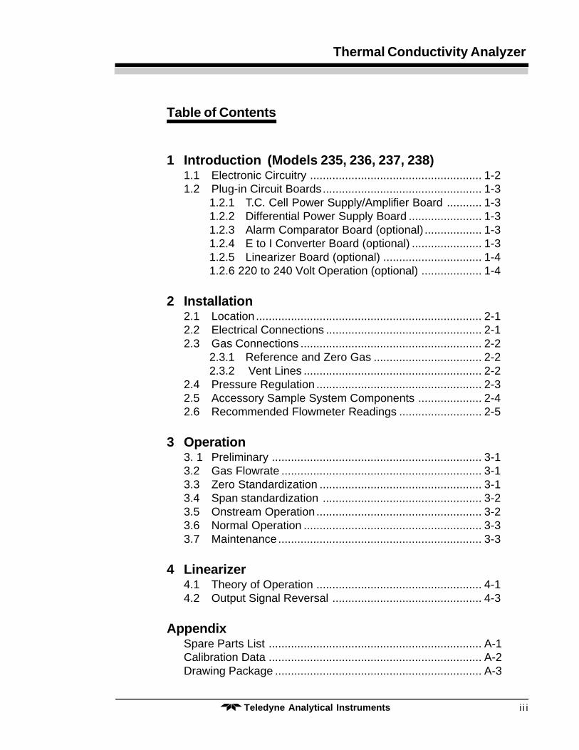
Table of Contents
1 Introduction (Models 235, 236, 237, 238)1.1 Electronic Circuitry ...................................................... 1-21.2 Plug-in Circuit Boards.................................................. 1-3
1.2.1 T.C. Cell Power Supply/Amplifier Board ........... 1-31.2.2 Differential Power Supply Board ....................... 1-31.2.3 Alarm Comparator Board (optional) .................. 1-31.2.4 E to I Converter Board (optional) ...................... 1-31.2.5 Linearizer Board (optional) ............................... 1-41.2.6 220 to 240 Volt Operation (optional) ................... 1-4
2 Installation2.1 Location ....................................................................... 2-12.2 Electrical Connections ................................................. 2-12.3 Gas Connections ......................................................... 2-2
2.3.1 Reference and Zero Gas .................................. 2-22.3.2 Vent Lines ........................................................ 2-2
2.4 Pressure Regulation .................................................... 2-32.5 Accessory Sample System Components .................... 2-42.6 Recommended Flowmeter Readings .......................... 2-5
3 Operation3. 1 Preliminary .................................................................. 3-13.2 Gas Flowrate ............................................................... 3-13.3 Zero Standardization ................................................... 3-13.4 Span standardization .................................................. 3-23.5 Onstream Operation .................................................... 3-23.6 Normal Operation ........................................................ 3-33.7 Maintenance ................................................................ 3-3
4 Linearizer4.1 Theory of Operation .................................................... 4-14.2 Output Signal Reversal ............................................... 4-3
AppendixSpare Parts List ................................................................... A-1Calibration Data ................................................................... A-2Drawing Package ................................................................. A-3
Teledyne Analytical Instrumentsi v
Model 235
COMBUSTIBLE GAS USAGE WARNING
DANGER
This is a general purpose instrument designed for usage in anonhazardous area. It is the customer's responsibility to en-sure safety especially when combustible gases are being ana-lyzed since the potential of gas leaks always exist.
The customer should ensure that the principles of operating ofthis equipment is well understood by the user. Misuse of thisproduct in any manner, tampering with its components, orunauthorized substitution of any component may adverselyaffect the safety of this instrument.
Since the use of this instrument is beyond the control ofTeledyne, no responsibility by Teledyne, its affiliates, andagents for damage or injury from misuse or neglect of thisequipment is implied or assumed.
1-1Teledyne Analytical Instruments
Thermal Conductivity Analyzer Introduction 1
Introduction (Models 235, 236, 237, 238)
The 235 Series Thermal Conductivity Analyzers measure the concen-tration of one component in a binary stream of gas, or the purity of a samplestream containing a composite mixture of impurities, by comparing thedifference in thermal conductivity of the sample stream with that of areference gas of fixed composition.
Control of the sample and supporting gases is not provided for in thebasic design TAI offers a variety of supporting gas control panels as com-panion accessories to the analyzer to fill this need. In any case, means mustbe provided for controlling the flowrates through the sample and referencepaths of the analyzer, and a control manifold will be required for the intro-duction of zero and span gas, as well as sample gas, into the sample path.Appropriate pressure reducing regulators will have to be installed at all gassupply sources; for those customers wishing to incorporate their ownsample controls, a recommended system piping schematic is included amongthe drawings at the rear of the manual.
Thermal conductivity measurements are non-specific by nature. Thisfact imposes certain limitations and requirements. If the user intends toemploy the analyzer to detect a specific component in a sample stream, thesample must be composed of the component of interest and one other gas inorder to be accurate.
If, on the other hand, the user is primarily interested in the purity of aprocess stream, and does not require specific identification of the impurity,the analyzer can be used on more complex mixtures. The impurities, then,can be a composition in themselves.
Teledyne Analytical Instruments1-2
1 Introduction Model 235
Because analysis by thermal conductivity is not an absolute measure-ment, standardization gases of known composition will be required to fixthe upper and lower parameters of the range (or ranges) of analysis. Thesegases will be used to periodically check the accuracy of the analyzer.
The difference in thermal conductivity between the fixed reference gasand the sample is sensed by hot wire elements. The elements are mounted ina cell assembly so that one set is in the reference and the other in the samplestream. Each set of elements is a component in an electrical bridge circuit.
During calibration, the bridge circuit is balanced in zero and referencegas at one end of the measurement range, and sensitized in reference andspan gas at the other end, so that intervening points along the range (orranges) of interest will produce a DC electrical signal representative of theanalysis. The resulting electrical signal is fed to an amplifier and span pot,which produce a standard 0-1V output signal. An E to I converter PC boardis also installed and produces an isolated 4–20 mA DC current output inaddition to the voltage output.
The temperature of the measuring cell is regulated to within 0.1 degreeC by a sophisticated control circuit. A thermistor is used to measure thetemperature, and a zero-crossing switch regulates the power in a cartridge-type heater. Temperature control is precise enough to eliminate diurnaleffects in the output over the operating ranges of the analyzer.
The overall design of the instrument is intended to facilitate servicingand troubleshooting, should that ever be necessary. The controls are allmounted on the front panel, which can swing down, allowing access to thecell compartment. The cell is enclosed in an insulated compartment that isreadily removable from the chassis; the electronics are mounted on a seriesof circuit boards at the rear of the enclosure, accessible by removing theback panel.
Explosion-proof models of the series use sealed explosion-proofenclosures for the analysis section (Model 237) or both the analysis sectionand control unit (Model 238). Model 235 is general purpose with remotecontrol unit, and Model 235 is general purpose with integral control unit.
1.1 Electronic Circuitry
The electronic components are mounted on a number of circuit boardsthat plug into sockets on a larger board, dubbed the “Mother Board”. Thisallows for rapid troubleshooting and repair of any defective parts, and alsofor rapid field installation of optional features not ordered with the unit.
1-3Teledyne Analytical Instruments
Thermal Conductivity Analyzer Introduction 1
All electrical interconnections are made to the terminal strips on themother board; this board also contains an unusual feature — a series ofregularly-spaced holes in a rectangular pattern, known as a “kludge” space,is set aside for the installation of circuitry for special customer requirements.
1.2 Plug-in Circuit Boards
Several options are available as convenient plug-in circuit boards;although these may not all be present in the specific instrument underconsideration, a brief description of some of the more common ones isoffered below, and noted as (optional); PC boards which are not noted as(optional) are standard features.
1.2.1 T.C. Cell Power Supply/Amplifier Board
This circuit contains an IC regulator that holds the voltage through thecell to 4.5 V. It also contains a 2-stage IC amplifier, with range resistors.
1.2.2 Differential Power Supply Board
15 Volts, regulated (for electronic amplifiers, etc.), and +24 volts, non-regulated (for alarm and relay circuitry and certain other functional uses) aresupplied by this circuit.
1.2.3 Alarm Comparator Board (optional)
The comparator alarm circuit is available in single or dual configura-tions, which can be supplied as high or low alarms, energized above orbelow setpoint; adjustment of each alarm setpoint is made using a potenti-ometer provided on the instrument’s front panel. Power failure or “fail-safe”alarming can also be provided. Refer to the specifications covering oneindividual analyzer for details regarding specific alarm or other optionalprovisions.
Teledyne Analytical Instruments1-4
1 Introduction Model 235
1.2.4 E to I Converter Board (standard)
The standard current output in the form of an isolated 4–20 mA dccurrent is supplied by the E to I converter circuit. The output of this boardis proportional to the percentage of range, for example, 4 mA for 0% and20 mA for 100% of range. This current output is in addition to the 0–1 V dcvoltage output.
1.2.5 Linearizer Board (optional)
An excellent alternative to the use of correction curves is available asan option with the Series 235 Analyzer. A digital linearizer circuit is avail-able as a plug-in PC board. This is a very flexible circuit that produces alinear correction to a wide variety of non-linear curves. The result is anoutput signal which is linear over the specified analysis range or ranges.When employed, the digital linearizer is transparent to the user and requiresno adjustment.
1.2.6 220 to 240 Volt Operation (optional)
The Series 235 analyzer is available for either 110-120 (standard) or220-240 (optional), 50 or 60 Hz operation.
2-1Teledyne Analytical Instruments
Thermal Conductivity Analyzer Installation 2
Installation
2.1 Location
The analyzer should be installed where it will not be subject to thefollowing conditions:
1. Direct sunlight
2. Drafts of air
3. Shock and vibration
4. Temperatures below 30° F or above 110° F
The analyzer should be placed as close as possible, subject to the aboveconditions, to the sample point to minimize the effects of sample line lagtime on the analysis.
An outline diagram, showing the location and identification of the gasline and electrical conduit connections, as well as the physical dimensions ofthe analyzer case, is included in the drawings at the rear of the manual.
2.2 Electrical Connections
A single-phase, 110 to 120 Volt, or 220 to 240 Volt, 50 or 60 Hz line,capable of delivering 2-1/2 amperes of current continuously, is required tooperate the analyzer. Primary power connections are made on the terminalstrip mounted on the mother board, behind the rear access cover. A solidwater-pipe ground should be provided for personnel protection. Whenconnecting the power source, polarize the connections as indicated on theinterconnection diagram at the rear of the manual.
Teledyne Analytical Instruments2-2
2 Installation Model 235 Series
Use 2-conductor shielded cable (nominally No. 22 wire size) to inter-connect the analyzer output signal with the recording equipment. The shieldshould be terminated on the appropriate terminal (see interconnectiondiagram) at the analyzer—and be left disconnected at the recorder.
2.3 Gas Connections
Customer gas connection points are located on the underside of theanalyzer case. (Standard, basic instrument)
(See Outline Diagram for identification of each point.)
2.3.1 Reference and Zero GasA constant supply of gas, of a fixed composition, is needed as the
reference to which the sample gas will be compared. The reference gas isnormally selected to represent the main background of the analysis. Forcertain applications, an optional sealed air reference is available where thereference side of the detector cell is filled with air and sealed. This elimi-nates the need to have reference gas constantly passing through the cell. Forinstruments equipped with the optional sealed air reference, there will not bereference inlet or vent ports.
A supply of gas, containing little or none of the components of interest,is required to zero-standardize the analyzer.
In order to satisfy the requirements, both of these gases must besupplied from purchased cylinder sources — as no other economical meansis readily available that will guarantee the user that impurities are maintainedat a low, fixed level.
Because most cylinder gases are supplied 99.95 to 99.98% pure, TBErecommends that one cylinder of gas be used to fill both needs for mostapplications (i.e., zero and reference.)
Specific recommendations as to the number and type of supportinggases required will be found listed in the calibration section of the manual.
It is essential to the accuracy of the analyzer that the purity of the zerogas be known. The zero control would be adjusted during zero standardiza-tion, so that the recorder indicates the impurity content of the zero gas,rather than zero.
2-3Teledyne Analytical Instruments
Thermal Conductivity Analyzer Installation 2
2.3.2 Vent LinesThe selected gas introduced into the sample path of the cell (zero,
span, and sample) is vented from one connection at the bottom of theanalyzer, and the reference gas is vented from another.
If it is desirable to carry these gases to an area remote from the ana-lyzer to vent them, the following precautions will have to be observed invent line installation:
1. The vent lines should be constructed of 1/4 inch tubing, so thatno appreciable back pressure resulting from restricted flow isexperienced by the analyzer.
2. Both the sample and reference lines must be vented into an areawhere the ambient pressure is the same.
3. The ambient pressure in the vent area must undergo no morethan normal barometric pressure changes.
4. The vent lines must be installed so that water and dirt cannotaccumulate in them.
2.4 Pressure Regulation
All incoming gas lines should be equipped with pressure regulators.
The sample line pressure regulator should be installed as close to thesample point as possible to minimize sample line lag time.
Sample pressure should be set somewhere between 5 and 50 psig—10psig is nominal.
To minimize flowrate adjustments, the pressure regulators on thesupporting gas supply cylinders should be adjusted to provide the sameoutput pressure as the sample line regulator.
When installing pressure regulators on supply cylinders, crack thecylinder valves so that gas is flowing during installation. Using this proce-dure will eliminate the most common cause of standardization gas contami-nation. Air trapped during assembly can, and will, diffuse back into thecylinder. This is particularly important in applications where impurities of 1and 2% are the range of interest.
Teledyne Analytical Instruments2-4
2 Installation Model 235 Series
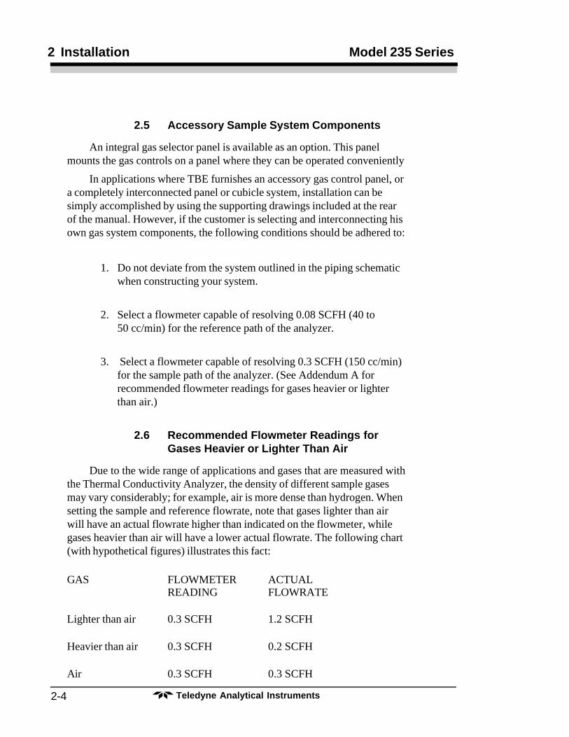
2.5 Accessory Sample System Components
An integral gas selector panel is available as an option. This panelmounts the gas controls on a panel where they can be operated conveniently
In applications where TBE furnishes an accessory gas control panel, ora completely interconnected panel or cubicle system, installation can besimply accomplished by using the supporting drawings included at the rearof the manual. However, if the customer is selecting and interconnecting hisown gas system components, the following conditions should be adhered to:
1. Do not deviate from the system outlined in the piping schematicwhen constructing your system.
2. Select a flowmeter capable of resolving 0.08 SCFH (40 to50 cc/min) for the reference path of the analyzer.
3. Select a flowmeter capable of resolving 0.3 SCFH (150 cc/min)for the sample path of the analyzer. (See Addendum A forrecommended flowmeter readings for gases heavier or lighterthan air.)
2.6 Recommended Flowmeter Readings forGases Heavier or Lighter Than Air
Due to the wide range of applications and gases that are measured withthe Thermal Conductivity Analyzer, the density of different sample gasesmay vary considerably; for example, air is more dense than hydrogen. Whensetting the sample and reference flowrate, note that gases lighter than airwill have an actual flowrate higher than indicated on the flowmeter, whilegases heavier than air will have a lower actual flowrate. The following chart(with hypothetical figures) illustrates this fact:
GAS FLOWMETER ACTUALREADING FLOWRATE
Lighter than air 0.3 SCFH 1.2 SCFH
Heavier than air 0.3 SCFH 0.2 SCFH
Air 0.3 SCFH 0.3 SCFH
2-5Teledyne Analytical Instruments
Thermal Conductivity Analyzer Installation 2
The analyzer is not flow sensitive during measurement; i.e., the OUT-PUT does not vary with the flow, but for maximum accuracy and repeat-ability, measurements should be made at the same flowrate used whencalibrating the analyzer.
TBE recommends, for lighter-than-air gas backgrounds, setting theflowmeter to a lower reading for reference and measurement; this willconserve gas. For example, for hydrogen or helium, set the flowmeterreading to 0.1 SCFH. A higher reading is recommended for heavier-than-air gas backgrounds, e.g., for carbon dioxide or argon, set the flowmeterto 0.4 SCFH.

Teledyne Analytical Instruments2-6
2 Installation Model 235 Series
3-1Teledyne Analytical Instruments
Thermal Conductivity Analyzer Operation 3
Operation
3. 1 Preliminary
• Check to see that all gases have been connected to the properports of the analyzer and that all gas connection lines are leak-free.
• Check to see that the power and signal wiring has been properlyinstalled.
• Check to see that the fuses in the analyzer are intact.
• Check to see that all PC Boards are intact and securely pluggedin.
• Turn the recorder and power switches to the “ON” position.
3.2 Gas Flowrate
Start the REFERENCE gas flow, and adjust the flowrate to approxi-mately 0.08 SCFH (40 cc/min.)
Start ZERO gas through the sample path of the analyzer, and adjustthe flowrate to approximately 0.3 SCFH (150 cc/min).
See Section 2.6 for additional flowrate information for gases lighter orheavier than air.
Allow the analyzer to run with zero and reference gas flowing forseveral hours before attempting calibration. This will permit the cell to cometo thermal equilibrium.
3.3 Zero Standardization
After the necessary temperature stabilization period, the analyzer canbe zero-standardized as follows:
NOTE: Before zero-standardization of the analyzer is possible, and whilethe power is off, the mechanical zero of the meter must bechecked. If the pointer does not rest at zero with the power off,then adjust the slotted screw found at a low center position of themeter face to correct. DO NOT allow this screw to be readjustedafter the zero-standardization has been performed. No mechanicalzero is used with digital meters.
Teledyne Analytical Instruments3-2
3 Operation Model 235 Series
1. Check to see that the span control is set at about 50% of itstravel. Some readjustment of this control may be necessaryduring standardization, but our concern at this point is to seethat a reasonable level of output signal is available to therecorder for zero standardization.
2. With multi-range analyzers, make sure that the range selectionswitch is on the “Range 1” position. As in Step No. 1, thisinsures a proper signal level for deriving a correct zero setting.
3. Check the sample path flowmeter to see that the zero gasflowrate is 0.3 SCFH.
4. Adjust the Zero control on the analyzer control panel until themeter indicates the impurity (if any) contained in the zero gas.
3.4 Span Standardization
After the zero setting has been accomplished, the span (or sensitivity)of the analyzer can be checked as follows:
1. Arrange the sample path so that span gas is flowing through theanalyzer.
2. Check the sample path flowmeter to see if the span gas isflowing at a 0.3 SCFH rate.
3 With mufti-range instruments, set the range selector switch onthe position that provides the highest resolution of the span gasconcentration.
4. Adjust the span control until the meter reads the correct value ofimpurity in the span gas.
3.5 Onstream Operation
After standardization has been successfully concluded, arrange thesample path so that sample gas is flowing through the analyzer at approxi-mately. 0.3 SCFH.
With multirange instruments, select the range of analysis that gives thebest recorder resolution of the process stream. The analyzer is now“onstream” and ready for use.
3-3Teledyne Analytical Instruments
Thermal Conductivity Analyzer Operation 3
3.6 Normal Operation
For routine operation of the analyzer, you should perform the follow-ing checks:
• Sample flow: Check the sample flowrate daily to insure properoperation.
• Reference gas flow: Check the reference gas flowrate daily—and the reference supply cylinder periodically—to insure againstaccidental depletion. Whenever it is necessary to replace thereference gas supply, the analyzer standardization proceduresmust be repeated.
• Standardization: The analyzer should be restandardized on amonthly schedule as a check of its performance.
3.7 Maintenance
Since there are no moving parts in the analyzer, no routine mainte-nance is required other than normal care of the instrument. The checklistabove should be adequate to keep the analyzer functioning properly formany years.
Teledyne Analytical Instruments3-4
3 Operation Model 235 Series
4-1TELEDYNE BROWN ENGINEERINGAnalytical Instruments
Thermal Conductivity Analyzer Linearizer 4
Linearizer
4.1 Theory of Operation
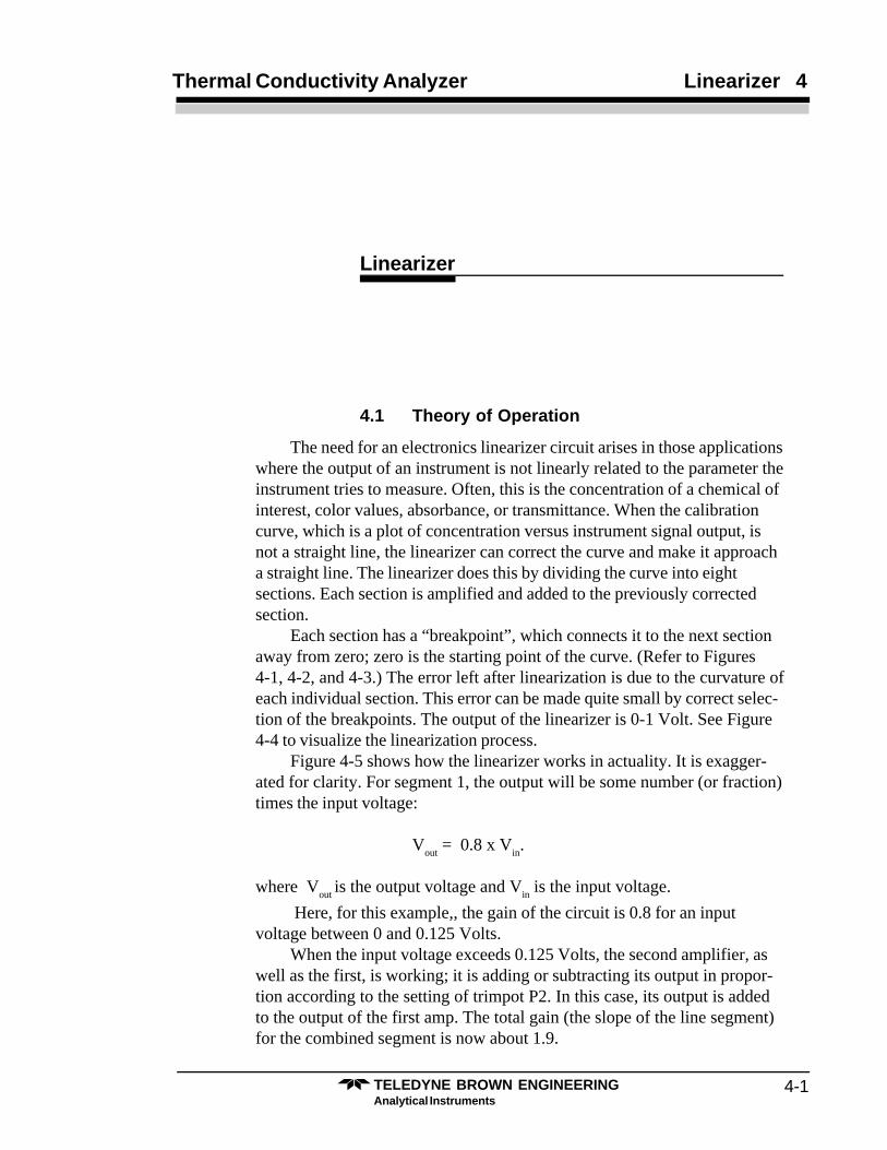
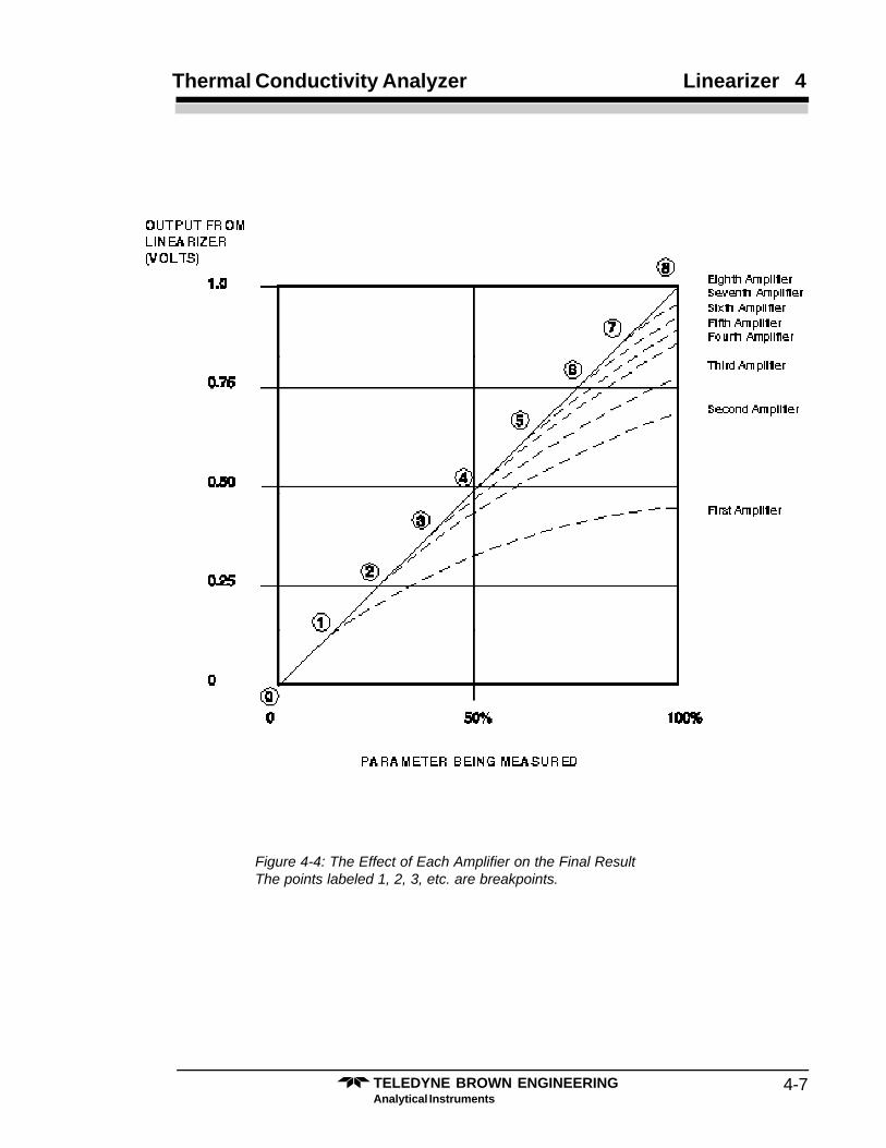
The need for an electronics linearizer circuit arises in those applicationswhere the output of an instrument is not linearly related to the parameter theinstrument tries to measure. Often, this is the concentration of a chemical ofinterest, color values, absorbance, or transmittance. When the calibrationcurve, which is a plot of concentration versus instrument signal output, isnot a straight line, the linearizer can correct the curve and make it approacha straight line. The linearizer does this by dividing the curve into eightsections. Each section is amplified and added to the previously correctedsection.
Each section has a “breakpoint”, which connects it to the next sectionaway from zero; zero is the starting point of the curve. (Refer to Figures4-1, 4-2, and 4-3.) The error left after linearization is due to the curvature ofeach individual section. This error can be made quite small by correct selec-tion of the breakpoints. The output of the linearizer is 0-1 Volt. See Figure4-4 to visualize the linearization process.
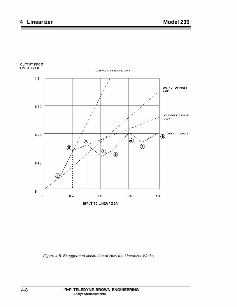
Figure 4-5 shows how the linearizer works in actuality. It is exagger-ated for clarity. For segment 1, the output will be some number (or fraction)times the input voltage:
Vout
= 0.8 x Vin.
where Vout
is the output voltage and Vin is the input voltage.
Here, for this example,, the gain of the circuit is 0.8 for an inputvoltage between 0 and 0.125 Volts.
When the input voltage exceeds 0.125 Volts, the second amplifier, aswell as the first, is working; it is adding or subtracting its output in propor-tion according to the setting of trimpot P2. In this case, its output is addedto the output of the first amp. The total gain (the slope of the line segment)for the combined segment is now about 1.9.
TELEDYNE BROWN ENGINEERINGAnalytical Instruments
4-2
4 Linearizer Model 235
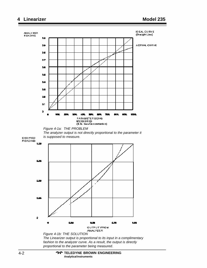
Figure 4-1b: THE SOLUTIONThe Linearizer output is proportional to its input in a complimentaryfashion to the analyzer curve. As a result, the output is directlyproportional to the parameter being measured.
Figure 4-1a: THE PROBLEMThe analyzer output is not directly proportional to the parameter itis supposed to measure.
4-3TELEDYNE BROWN ENGINEERINGAnalytical Instruments
Thermal Conductivity Analyzer Linearizer 4
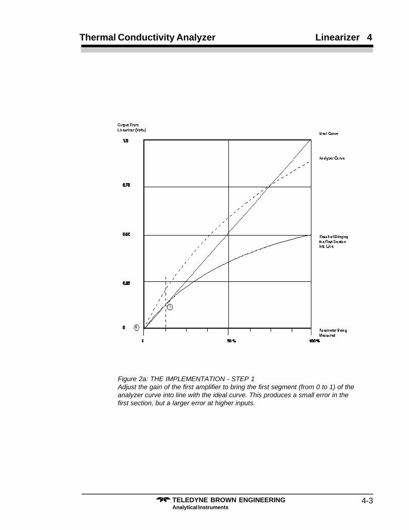
Figure 2a: THE IMPLEMENTATION - STEP 1Adjust the gain of the first amplifier to bring the first segment (from 0 to 1) of theanalyzer curve into line with the ideal curve. This produces a small error in thefirst section, but a larger error at higher inputs.
TELEDYNE BROWN ENGINEERINGAnalytical Instruments
4-4
4 Linearizer Model 235
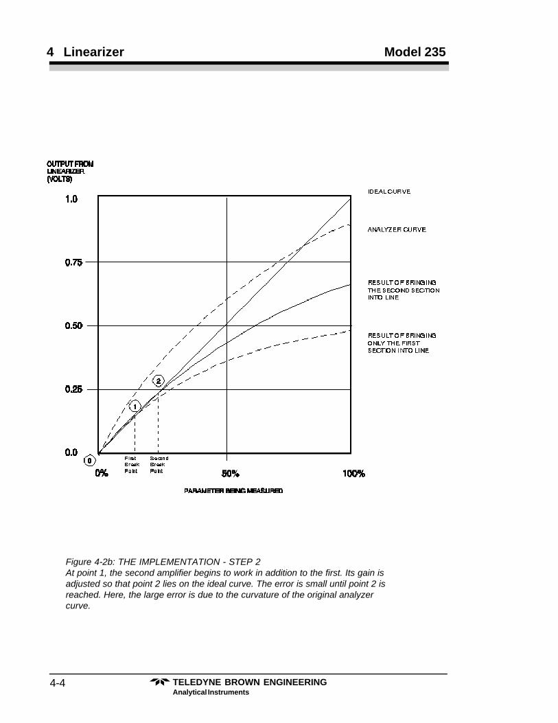
Figure 4-2b: THE IMPLEMENTATION - STEP 2At point 1, the second amplifier begins to work in addition to the first. Its gain isadjusted so that point 2 lies on the ideal curve. The error is small until point 2 isreached. Here, the large error is due to the curvature of the original analyzercurve.
4-5TELEDYNE BROWN ENGINEERINGAnalytical Instruments
Thermal Conductivity Analyzer Linearizer 4
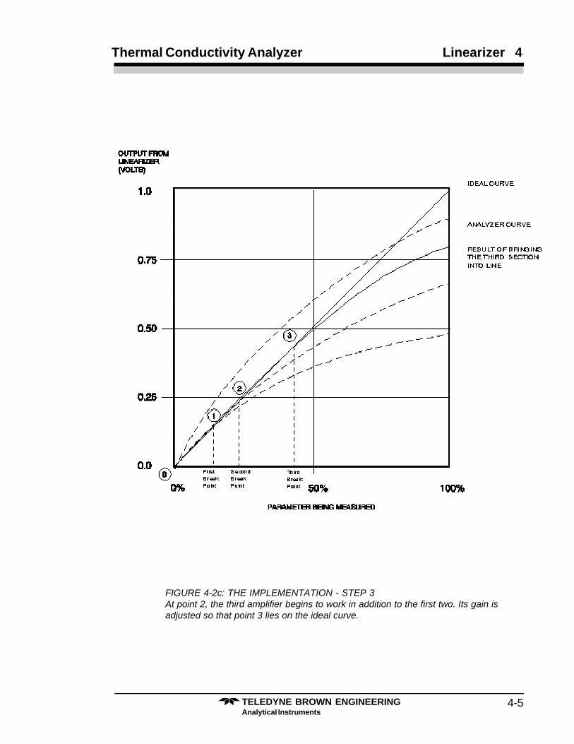
FIGURE 4-2c: THE IMPLEMENTATION - STEP 3At point 2, the third amplifier begins to work in addition to the first two. Its gain isadjusted so that point 3 lies on the ideal curve.
TELEDYNE BROWN ENGINEERINGAnalytical Instruments
4-6
4 Linearizer Model 235
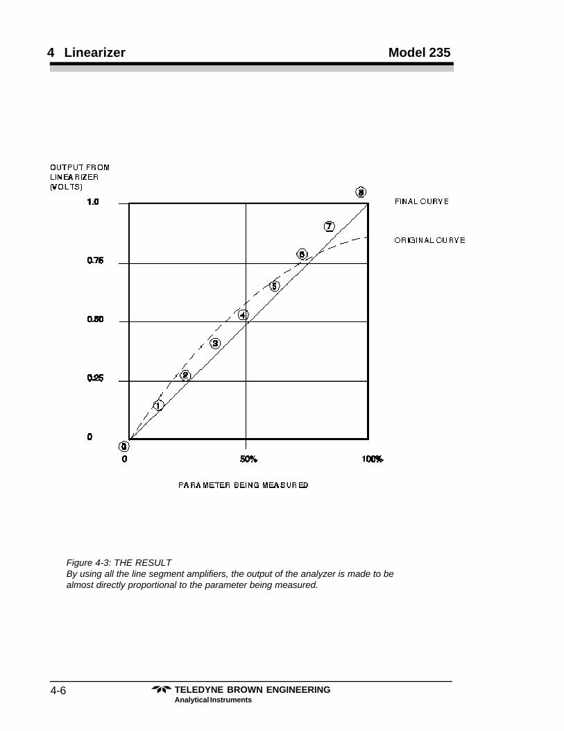
Figure 4-3: THE RESULTBy using all the line segment amplifiers, the output of the analyzer is made to bealmost directly proportional to the parameter being measured.
4-7TELEDYNE BROWN ENGINEERINGAnalytical Instruments
Thermal Conductivity Analyzer Linearizer 4
Figure 4-4: The Effect of Each Amplifier on the Final ResultThe points labeled 1, 2, 3, etc. are breakpoints.
TELEDYNE BROWN ENGINEERINGAnalytical Instruments
4-8
4 Linearizer Model 235
Figure 4-5: Exaggerated Illustration of How the Linearizer Works
4-9TELEDYNE BROWN ENGINEERINGAnalytical Instruments
Thermal Conductivity Analyzer Linearizer 4
When the voltage exceeds 0.25 Volts, the third amplifier works, alongwith the first two, adding or subtracting its output in proportion, accordingto the setting of its trimpot, P3. The gain is now the sum of all three gains.In this case, the gain of the third amp is negative, so the total gain is about0.3.
As the input voltage exceeds each breakpoint, another amplifier joinsin. The slope of each line segment is equal to the sum of the gain of all theamplifiers in operation at that particular time. The gain of each amplifier isset by its trimpot. The first amplifier has a gain range of 0 to +4, and all theothers about -3 to +3.
The maximum slope obtainable is limited. Setting the gain too high willresult in the amplifier saturating. However, with the dynamic range inherentin these amplifiers, this is not likely to happen.
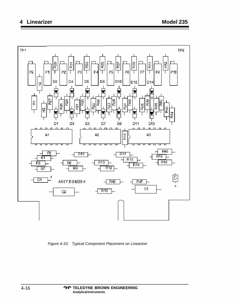
The breakpoints are factory-set by the values of resistors R6, R8, R10,R-12, R14, R16, and R18. See Figure 4-10 for location of these resistors.
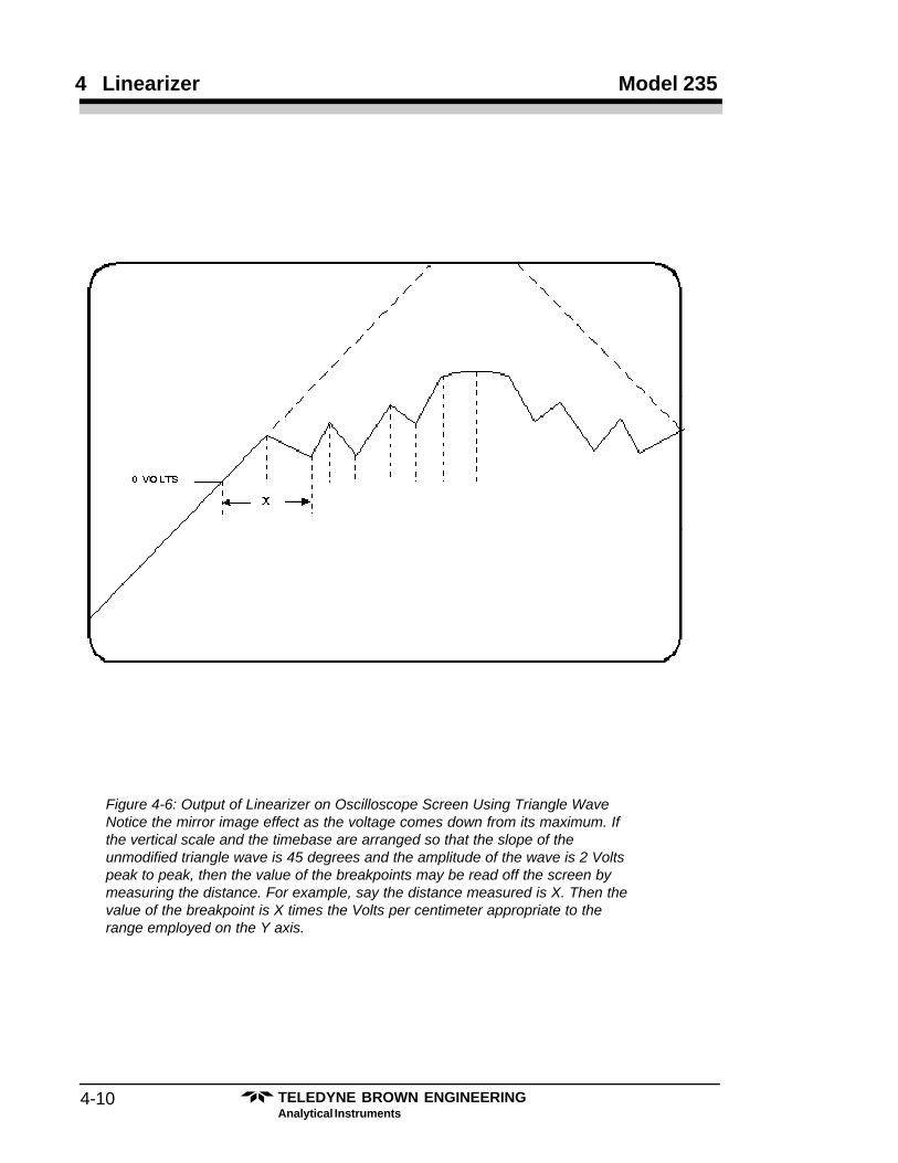
The most efficient way to check the operation of the linearizer circuitis to drive it using a 1 kHz. triangular wave of 2 Volts peak-to-peak ampli-tude as shown in Figure 4-6. The effect of the breakpoints and trimpots canthen readily be seen; if you alternate the gain of the stages, a jagged stepeffect can be produced. This will show the breakpoints clearly. Alterna-tively, a DVM may be attached to the junction of D2 and R20; this junctionpoint accesses the output of a line segment amplifier. As the input voltage isgradually increased, the DVM at some point will indicate a negative volt-age. At this point, a breakpoint has been passed. Repeat this test for eachline segment amplifier to determine its breakpoint.
4.2 Linearizer Circuit Theory
Refer to Figure 4-10 for the component position in the followingdiscussion. AlA is a non-inverting buffer and amplifier with a gain of 2.5,zeroed with P9. Its output is checked for zero at test point 1 (TP1). R1provides a bias path in case the input is not DC-loaded.
The amplified output is brought to the inverting inputs of line segmentamplifiers AlB, A1C, A1D, A2A, A2B, A2C, A2D, and A3A, throughresistors R5, R7, R9, R11, R13, R15, R17, and R19.
A1D is configured differently from the other line segment amplifiers. Itis simply an inverting amplifier with P1 as its feedback resistor to set itsgain. The gain for this amplifier may be set between 0 and 4.
The other line segment amplifiers work in a similar fashion. Let usexamine A1C, for example. Refer to Figure 4-7 for the following analysis ofa typical line segment amplifier.
TELEDYNE BROWN ENGINEERINGAnalytical Instruments
4-10
4 Linearizer Model 235
Figure 4-6: Output of Linearizer on Oscilloscope Screen Using Triangle WaveNotice the mirror image effect as the voltage comes down from its maximum. Ifthe vertical scale and the timebase are arranged so that the slope of theunmodified triangle wave is 45 degrees and the amplitude of the wave is 2 Voltspeak to peak, then the value of the breakpoints may be read off the screen bymeasuring the distance. For example, say the distance measured is X. Then thevalue of the breakpoint is X times the Volts per centimeter appropriate to therange employed on the Y axis.
4-11TELEDYNE BROWN ENGINEERINGAnalytical Instruments
Thermal Conductivity Analyzer Linearizer 4
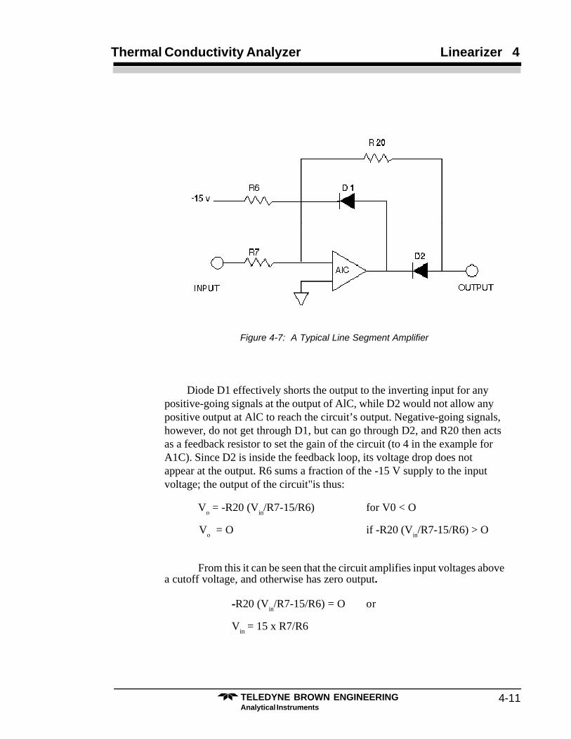
Figure 4-7: A Typical Line Segment Amplifier
Diode D1 effectively shorts the output to the inverting input for anypositive-going signals at the output of AlC, while D2 would not allow anypositive output at AlC to reach the circuit’s output. Negative-going signals,however, do not get through D1, but can go through D2, and R20 then actsas a feedback resistor to set the gain of the circuit (to 4 in the example forA1C). Since D2 is inside the feedback loop, its voltage drop does notappear at the output. R6 sums a fraction of the -15 V supply to the inputvoltage; the output of the circuit"is thus:
Vo = -R20 (V
in/R7-15/R6) for V0 < O
Vo = O if -R20 (V
in/R7-15/R6) > O
From this it can be seen that the circuit amplifies input voltages abovea cutoff voltage, and otherwise has zero output.
-R20 (Vin/R7-15/R6) = O or
Vin = 15 x R7/R6
TELEDYNE BROWN ENGINEERINGAnalytical Instruments
4-12
4 Linearizer Model 235
The negative supply voltage is -15 Volts. A similar expression for theoutput is V
out= -4(V
in - V
cutoff).
Notice that Vin is actually 2.5 times the voltage at the linearizer input,
due to the gain of AlA. This gain acts to minimize the effect of offset errors.The cutoff voltage (V
cutoff) is set by the choice of R6; the “breakpoint”
referenced to the input is approximately Vcutoff
/2.5. Thus:
R6 = 15xR7x 12.5 x Vbkpt
or (299.4/ Vbkpt
) K ohms
Note: Each amplifier amplifies everything above its cutoff voltage, and notjust a segment between two cutoff voltages.
The output of each amplifier other than A1D is brought to the slider ofa trimpot. One end of the pot goes through a resistor (e.g., R28) to thesumming node of the output amp, A3B. The other end of the pot goesthrough another resistor (e.g. R29) to the summing node of the inverterA3C.
The output from the inverter is then also brought into the summingnode of the output amp A3B. Clearly the position of the slider on pot P2will determine how much, signal goes directly into the summing input ofA3B, and now much goes through the inverter. If the slider is up at the top,almost all of the output of AlC will add to the output of A1D. If the slider isdown at the bottom, then the output of A1C will be subtracted from that ofAlD. If the slider is in the middle, the output will be added and subtracted inthe same amount and thus will have no effect.
So, we see that the gain of the first section of the curve from 0 to thefirst breakpoint is set at some value, (A), with P1. The gain of the secondsection of the curve is the value (A) plus a value (B), which is set by P2.The gain of the third breakpoint then, would be the sum, (A+B), plus a thirdvalue, (C), set by P3. In other words, each pot affects the gain of all thesections above where it starts working.
The gain of A3C is kept low by the small value of R43 (2K). This is tostop it from saturating if it gets too much input from all the amplifiers. Theresistor that sums its output into A3B, (R44), is selected at 2K to compen-sate for this.
A3B has a gain of about 0.3 to compensate for the gain of AlA and toreduce zero errors. It also sums all the positive contributions via R44 andA3C. Finally, it provides a low impedance output for the circuit.
4-13TELEDYNE BROWN ENGINEERINGAnalytical Instruments
Thermal Conductivity Analyzer Linearizer 4
4.3 Selection of Breakpoint Resistors
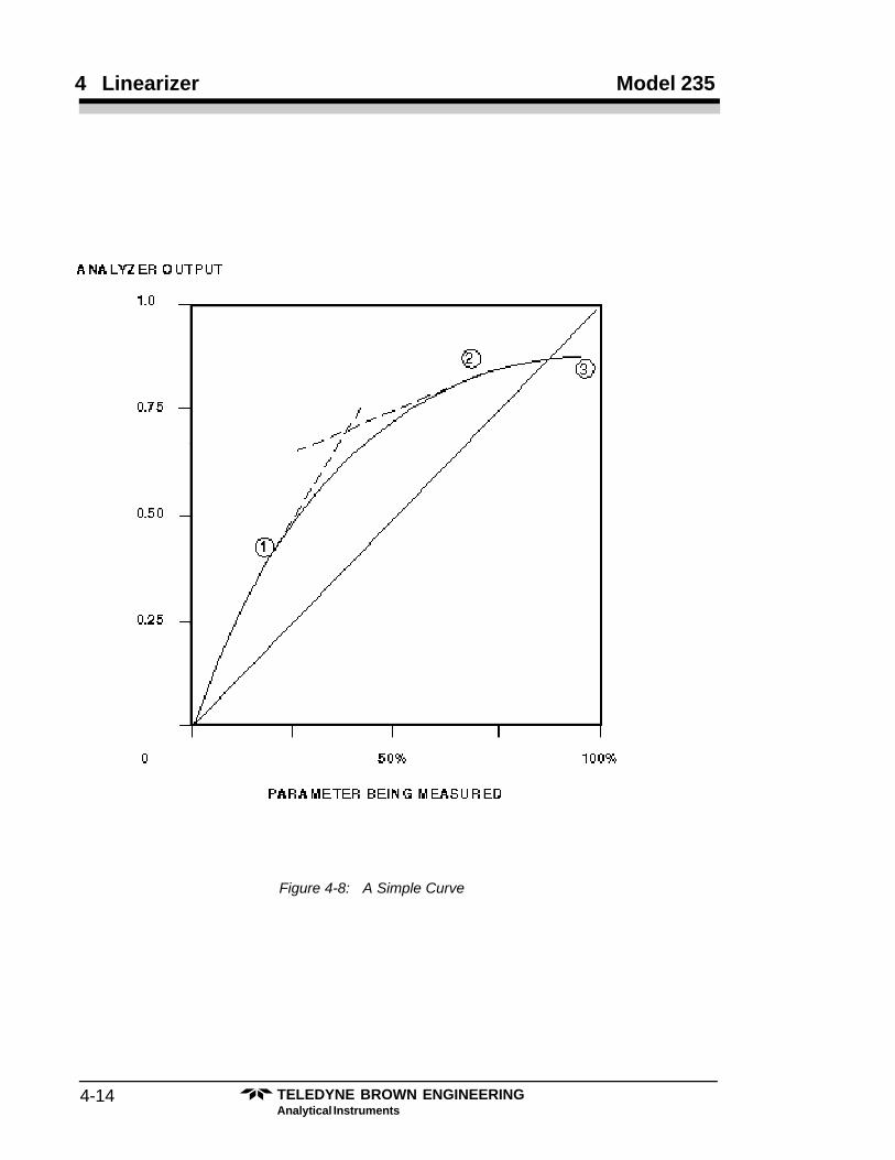
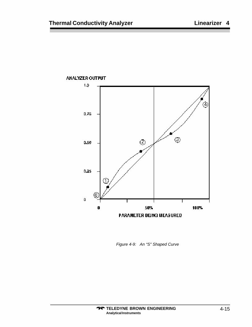
It may de desirable to concentrate the breakpoints in some areas of thevoltage range. For example: between 0 and 1in Figure 4-8, the curve isfairly straight. Between 2 and 3, the curve is modestly straight but with lessslope. Between 1 and 2, however, the it appears substantially curved. Sincethe linearizer is to approximate the curve with a series of straight lines, wewould like to have most of the segments on the curved segment; i.e.,between 1 and 2. This means that most of the breakpoints must be between1 and 2 rather than evenly spaced out. Similarly for the “S” curve shown inFigure 4-9, the breakpoints would be concentrated between the points 1–2and 3–4.
The resistors for the breakpoints are set according to the formula:
R = 299.4/Vbkpt
.
where Vbkpt
is the voltage at the particular breakpoint.The resistors affected are R6, R8, R10, R12, R14, R16 and R18 where
R6 is the first breakpoint.
TELEDYNE BROWN ENGINEERINGAnalytical Instruments
4-14
4 Linearizer Model 235
Figure 4-8: A Simple Curve
4-15TELEDYNE BROWN ENGINEERINGAnalytical Instruments
Thermal Conductivity Analyzer Linearizer 4
Figure 4-9: An “S” Shaped Curve
TELEDYNE BROWN ENGINEERINGAnalytical Instruments
4-16
4 Linearizer Model 235
Figure 4-10: Typical Component Placement on Linearizer
4-17TELEDYNE BROWN ENGINEERINGAnalytical Instruments
Thermal Conductivity Analyzer Linearizer 4
4.4 How to Use the Linearizer
Refering to Figure 4-10 for positioning of the Linearizer components,check to see that the proper breakpoint resistors are installed. Also, refer tothe Linearizer drawings that have been included in the Appendix.
4.4.1 Nulling Amplifiers A1A
1. Short the input (pin 3) to the common of the diff. powersupply.
2. Connect a DVM to TP1 (testpoint 1 is located on the PCboard)
3. Adjust trimpot P9 until the DVM reads 0 mV ±10 mV.
4.4.2 Nulling the Entire Linearizer Input to Output
1. Maintain the shorted input of A1A. (See step 1 above.)2. Connect the DVM to the output of the linearizer (pin 7
of A3B).3. Adjust trimpot P10 until the DVM reads 0 mV ±10 mV.
4.4.3 Linearizing the Calibration Curve
The calibration curve must be known at this point and found to be non-linear. This calibration can be done using known samples.
The curve has been studied, and breakpoint positions determined onthe most curved portions of the curve. Appropriate breakpoint resistorshave been installed.
1. Remove the shorting jumper previously installed fornulling steps.
2. Connect a DC voltage source to the input of AlA (pin 3)and ground. (The DVM is still connected to pin 7 ofA3B.)
3. Apply 0 volts to the input, (Vin). The output, (V
out) must
read 0 volts as well.4. Make V
in = V
test (1) per chart. This is the first breakpoint
voltage. NOTE: Vin must always be positive. Adjust P1
until Vout
= Vlin
(1) per chart. NOTE: make sure P1changes V
out.
TELEDYNE BROWN ENGINEERINGAnalytical Instruments
4-18
4 Linearizer Model 235
5. Make Vin = V
test (2) per chart. This is the second
breakpoint voltage. Adjust P2 until Vout
= Vlin
(2).6. Continue up each line segment, repeating the procedures
of the sections just covered, using pots P3, P4, P5, P6,P7, and P8, to linearize line segments 3, 4, 5, 6, 7, and 8.
7. Repeat the calibration against known samples, and verifythat the values obtained at various concentrations arelinearly displayed.
8. If the linearity is not quite satisfactory, determine whichline segment requires touch-up. If more than onesegment is not properly adjusted, readjust the segmentclosest to zero first. All other following segments mustbe toucned up, since they are affected by the former one.If results are still not satisfactory, re-evaluate thebreakpoints. Change their positions on the curve asrequired by installing different values for breakpointresistors. Repeat the line segment trimpot adjustmentprocedures as outlined in the above sections.
A-1Teledyne Analytical Instruments
Thermal Conductivity Analyzer Appendix
Appendix
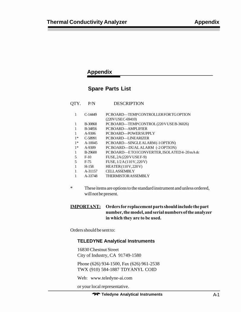
Spare Parts List
QTY. P/N DESCRIPTION
1 C-14449 PC BOARD—TEMP CONTROLLER FOR TG OPTION(220V USE C-69410)
1 B-30868 PC BOARD—TEMP CONTROL (220 V USE B-36026)1 B-34856 PC BOARD—AMPLIFIER1 A-9306 PC BOARD—POWER SUPPLY1* C-58991 PC BOARD—LINEARIZER1* A-10045 PC BOARD—SINGLE ALARM (-1 OPTION)1* A-9309 PC BOARD—DUAL ALARM (-2 OPTION)1 B-29600 PC BOARD—E TO I CONVERTER, ISOLATED 4–20 mA dc5 F-10 FUSE, 2A (220 V USE F-9)5 F-75 FUSE, 1/2 A (110 V, 220 V)1 H-158 HEATER (110 V, 220 V)1 A-31157 CELL ASSEMBLY1 A-33748 THERMISTOR ASSEMBLY
* These items are options to the standard instrument and unless ordered,will not be present.
IMPORTANT: Orders for replacement parts should include the partnumber, the model, and serial numbers of the analyzerin which they are to be used.
Orders should be sent to:
TELEDYNE Analytical Instruments
16830 Chestnut StreetCity of Industry, CA 91749-1580
Phone (626) 934-1500, Fax (626) 961-2538TWX (910) 584-1887 TDYANYL COID
Web: www.teledyne-ai.com
or your local representative.
Teledyne Analytical InstrumentsA-2
Appendix Model 235
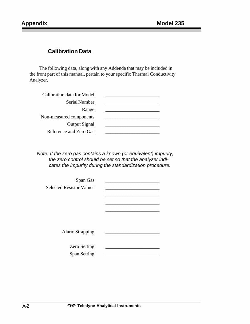
Calibration Data
The following data, along with any Addenda that may be included inthe front part of this manual, pertain to your specific Thermal ConductivityAnalyzer.
Calibration data for Model: ______________________
Serial Number: ______________________
Range: ______________________
Non-measured components: ______________________
Output Signal: ______________________
Reference and Zero Gas: ______________________
Note: If the zero gas contains a known (or equivalent) impurity,the zero control should be set so that the analyzer indi-cates the impurity during the standardization procedure.
Span Gas: ______________________
Selected Resistor Values: ______________________
______________________
______________________
______________________
Alarm Strapping: ______________________
Zero Setting: ______________________
Span Setting: ______________________