Embed Size (px)
Citation preview
III European Conference on Computational Mechanics Solids, Structures and Coupled Problems in Engineering
C.A. Mota Soares et.al. (eds.) Lisbon, Portugal, 5–8 June 2006
MODE DECOUPLING IN VEHICLE SUSPENSIONS APPLIED TO RACE CARS
Basileios Mavroudakis, Peter Eberhard
Institute of Engineering and Computational Mechanics, University of Stuttgart Pfaffenwaldring9, 70569, Stuttgart, Germany
e-mail: [mavroudakis, eberhard]@itm.uni-stuttgart.de
Keywords: Mode Decoupling Systems, Race Car Suspension, Vehicle Dynamics
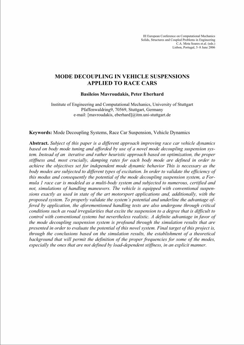
Abstract. Subject of this paper is a different approach improving race car vehicle dynamics based on body mode tuning and afforded by use of a novel mode decoupling suspension sys-tem. Instead of an iterative and rather heuristic approach based on optimization, the proper stiffness and, most crucially, damping rates for each body mode are defined in order to achieve the objectives set for independent mode dynamic behavior This is necessary as the body modes are subjected to different types of excitation. In order to validate the efficiency of this modus and consequently the potential of the mode decoupling suspension system, a For-mula 1 race car is modeled as a multi-body system and subjected to numerous, certified and not, simulations of handling maneuvers. The vehicle is equipped with conventional suspen-sions exactly as used in state of the art motorsport applications and, additionally, with the proposed system. To properly validate the system’s potential and underline the advantage of-fered by application, the aforementioned handling tests are also undergone through critical conditions such as road irregularities that excite the suspension to a degree that is difficult to control with conventional systems but nevertheless realistic. A definite advantage in favor of the mode decoupling suspension system is profound through the simulation results that are presented in order to evaluate the potential of this novel system. Final target of this project is, through the conclusions based on the simulation results, the establishment of a theoretical background that will permit the definition of the proper frequencies for some of the modes, especially the ones that are not defined by load-dependent stiffness, in an explicit manner.
Basileios Mavroudakis, Peter Eberhard
2
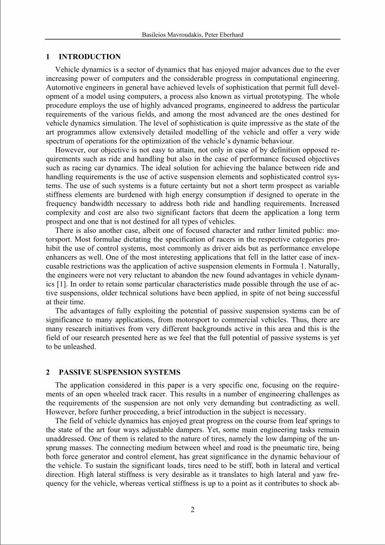
1 INTRODUCTION Vehicle dynamics is a sector of dynamics that has enjoyed major advances due to the ever
increasing power of computers and the considerable progress in computational engineering. Automotive engineers in general have achieved levels of sophistication that permit full devel-opment of a model using computers, a process also known as virtual prototyping. The whole procedure employs the use of highly advanced programs, engineered to address the particular requirements of the various fields, and among the most advanced are the ones destined for vehicle dynamics simulation. The level of sophistication is quite impressive as the state of the art programmes allow extensively detailed modelling of the vehicle and offer a very wide spectrum of operations for the optimization of the vehicle’s dynamic behaviour.
However, our objective is not easy to attain, not only in case of by definition opposed re-quirements such as ride and handling but also in the case of performance focused objectives such as racing car dynamics. The ideal solution for achieving the balance between ride and handling requirements is the use of active suspension elements and sophisticated control sys-tems. The use of such systems is a future certainty but not a short term prospect as variable stiffness elements are burdened with high energy consumption if designed to operate in the frequency bandwidth necessary to address both ride and handling requirements. Increased complexity and cost are also two significant factors that deem the application a long term prospect and one that is not destined for all types of vehicles.
There is also another case, albeit one of focused character and rather limited public: mo-torsport. Most formulae dictating the specification of racers in the respective categories pro-hibit the use of control systems, most commonly as driver aids but as performance envelope enhancers as well. One of the most interesting applications that fell in the latter case of inex-cusable restrictions was the application of active suspension elements in Formula 1. Naturally, the engineers were not very reluctant to abandon the new found advantages in vehicle dynam-ics [1]. In order to retain some particular characteristics made possible through the use of ac-tive suspensions, older technical solutions have been applied, in spite of not being successful at their time.
The advantages of fully exploiting the potential of passive suspension systems can be of significance to many applications, from motorsport to commercial vehicles. Thus, there are many research initiatives from very different backgrounds active in this area and this is the field of our research presented here as we feel that the full potential of passive systems is yet to be unleashed.
2 PASSIVE SUSPENSION SYSTEMS The application considered in this paper is a very specific one, focusing on the require-
ments of an open wheeled track racer. This results in a number of engineering challenges as the requirements of the suspension are not only very demanding but contradicting as well. However, before further proceeding, a brief introduction in the subject is necessary.
The field of vehicle dynamics has enjoyed great progress on the course from leaf springs to the state of the art four ways adjustable dampers. Yet, some main engineering tasks remain unaddressed. One of them is related to the nature of tires, namely the low damping of the un-sprung masses. The connecting medium between wheel and road is the pneumatic tire, being both force generator and control element, has great significance in the dynamic behaviour of the vehicle. To sustain the significant loads, tires need to be stiff, both in lateral and vertical direction. High lateral stiffness is very desirable as it translates to high lateral and yaw fre-quency for the vehicle, whereas vertical stiffness is up to a point as it contributes to shock ab-
Basileios Mavroudakis, Peter Eberhard
3
sorption. Unfortunately, decoupling of these two qualities is yet to be achieved, although there are some novel researched projects in that direction, so a tire stiff in the lateral direction will inevitably be overly stiff in the vertical one. Apart from being overly stiff, tires are also in-adequately damped elements, as the air contained cannot provide more than minimal damping. This in turn makes the definition of the suspension damping ratio a great challenge as to prop-erly damp the wheel motion the damping ratio will be excessive for the vehicle body move-ment with respect to the wheels. A two degree of freedom model, the so called quarter car model, resulting in two modes can very easily highlight the aforementioned damping problem.
The quarter car model of the vehicle may be adequate to underline this intrinsic problem the engineer has to solve or to provide a good starting basis for ride optimization problems but is by no means already adequate for proper vehicle dynamics analysis. Introducing the de-grees of freedom that characterize the real world motion of a vehicle also increases the num-ber of possible modes. Starting with the supposition that the vehicle consists of rigid elements, the modes that are of particular interest to the analysis of the dynamic behaviour can be sum-moned to the following groups:
a) yaw and lateral mode, defined by tire lateral stiffness characteristics and tire static loads b) bounce, pitch, roll on tires, where the suspension travel is minimal compared to the body
motion with respect to the ground and the vehicle is practically suspended on the tires, de-fined by tire vertical stiffness characteristics
c) bounce, pitch, roll, warp on suspension, where the suspension travel is maximal com-pared to the body motion with respect to the ground, defined by the suspension elements’ stiffness and damping characteristics
The modes of group a) are practically unaffected by the suspension characteristics and rely on the tire specification of lateral stiffness and vehicle specification (weight distribution, wheelbase, tire pressure, etc). Careful but simple computations suffice to define the ratio be-tween front and rear lateral stiffness for the vehicle specification, in order to decouple the two modes and induce the desired steady state cornering characteristics, neutral or slightly uder-steering in the case of track racers. The overall tire stiffness is set as high as possible in order to ensure crisp response.
Groups b) and c) have to be examined together. In similar manner to the quarter car model where one degree of freedom effectively corresponds to suspended body displacement with respect to the ground and the other to significant wheel travel and minimal body displace-ment, group b) can be considered a direct analogous to the first quarter car mode whereas group c) to the second. Thus, presuming that the modes in each group are decoupled, a proper analysis can result into an ideal compromise between body and wheel movement. Minimiza-tion of the first is particularly desirable to avoid aerodynamic instabilities while of the second is necessary to maximize the tire contact patch and minimize load perturbation on tires, a fact that due to the non-linear tire behaviour limits the overall lateral force generation and conse-quently the cornering ability of the vehicle. It is worth noting that a similar balance is sought after in public vehicles, whereby the objectives are ride comfort and cornering safety through progressive and predictable handling respectively.
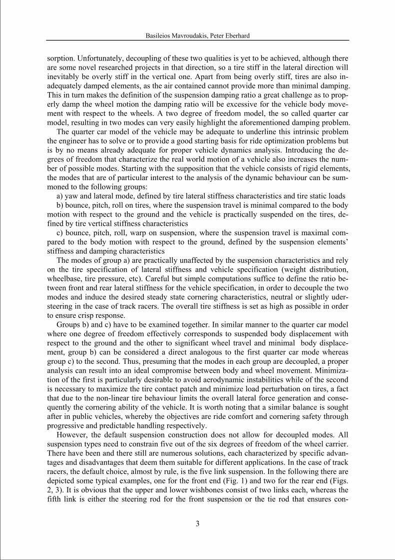
However, the default suspension construction does not allow for decoupled modes. All suspension types need to constrain five out of the six degrees of freedom of the wheel carrier. There have been and there still are numerous solutions, each characterized by specific advan-tages and disadvantages that deem them suitable for different applications. In the case of track racers, the default choice, almost by rule, is the five link suspension. In the following there are depicted some typical examples, one for the front end (Fig. 1) and two for the rear end (Figs. 2, 3). It is obvious that the upper and lower wishbones consist of two links each, whereas the fifth link is either the steering rod for the front suspension or the tie rod that ensures con-
Basileios Mavroudakis, Peter Eberhard
4
straining the fifth degree of freedom for the rear wheels. This particular layout has been estab-lished in motorsport for many reasons, most notably the excellent and tuneable wheel kine-matics qualities, particularly regarding wheel carrier orientation with respect to wheel travel in suspension operation, unobtrusive air flow and low unspung weight, particularly when combined with pushrods whereby the links are not burdened with sustaining bending loads.
Figure 1: Front suspension layout
Pushrods are also desirable for allowing specification of the wheel rate, which is the ratio
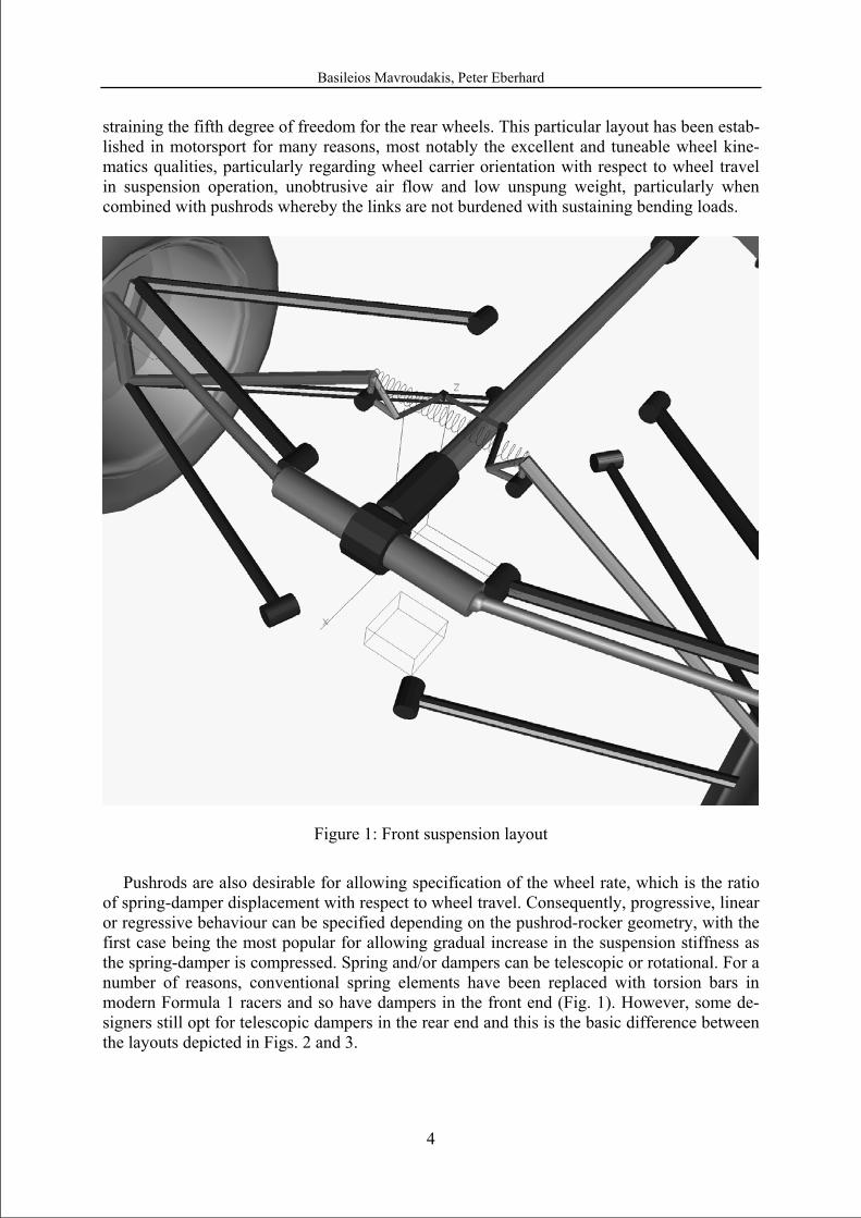
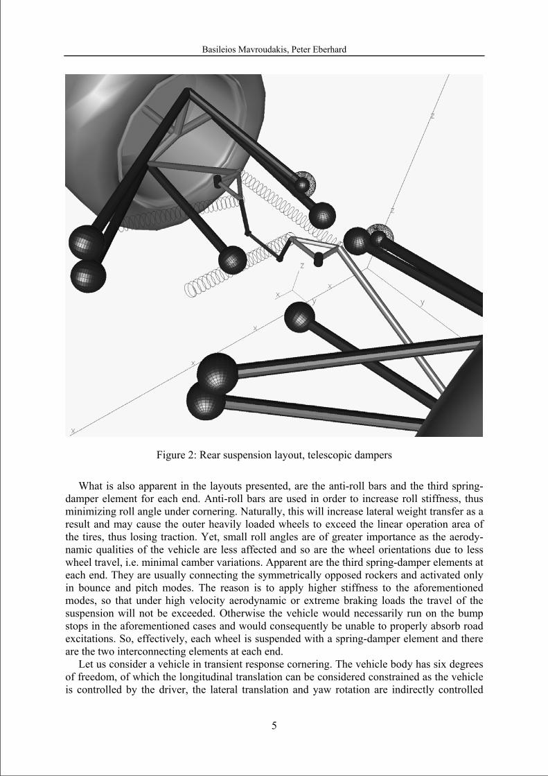
of spring-damper displacement with respect to wheel travel. Consequently, progressive, linear or regressive behaviour can be specified depending on the pushrod-rocker geometry, with the first case being the most popular for allowing gradual increase in the suspension stiffness as the spring-damper is compressed. Spring and/or dampers can be telescopic or rotational. For a number of reasons, conventional spring elements have been replaced with torsion bars in modern Formula 1 racers and so have dampers in the front end (Fig. 1). However, some de-signers still opt for telescopic dampers in the rear end and this is the basic difference between the layouts depicted in Figs. 2 and 3.
Basileios Mavroudakis, Peter Eberhard
5
Figure 2: Rear suspension layout, telescopic dampers
What is also apparent in the layouts presented, are the anti-roll bars and the third spring-
damper element for each end. Anti-roll bars are used in order to increase roll stiffness, thus minimizing roll angle under cornering. Naturally, this will increase lateral weight transfer as a result and may cause the outer heavily loaded wheels to exceed the linear operation area of the tires, thus losing traction. Yet, small roll angles are of greater importance as the aerody-namic qualities of the vehicle are less affected and so are the wheel orientations due to less wheel travel, i.e. minimal camber variations. Apparent are the third spring-damper elements at each end. They are usually connecting the symmetrically opposed rockers and activated only in bounce and pitch modes. The reason is to apply higher stiffness to the aforementioned modes, so that under high velocity aerodynamic or extreme braking loads the travel of the suspension will not be exceeded. Otherwise the vehicle would necessarily run on the bump stops in the aforementioned cases and would consequently be unable to properly absorb road excitations. So, effectively, each wheel is suspended with a spring-damper element and there are the two interconnecting elements at each end.
Let us consider a vehicle in transient response cornering. The vehicle body has six degrees of freedom, of which the longitudinal translation can be considered constrained as the vehicle is controlled by the driver, the lateral translation and yaw rotation are indirectly controlled
Basileios Mavroudakis, Peter Eberhard
6
through the steering wheel input and indirectly affected by the suspension operation, while the bounce translation, pitch and roll rotation are directly affected by the suspension properties. We also have the four degrees of freedom resulting from the suspension travel for each wheel (tire slip angles or wheel carrier yaw orientations are constrained through the steering system). The seven degrees of freedom that are of interest can be parallelized to the b) and c) groups if we consider bounce, pitch, roll and warp instead of independent movement for each wheel. It is also apparent that the four body modes are coupled and the use of devices such as the anti-roll bars or the third spring-damper at each end offers a partial decoupling of the modes which is desirable as each mode requires different levels of stiffness and damping.
Figure 3: Rear suspension layout, rotational dampers
3 TRACK RACING REQUIREMENTS Track racing is an immensely competent racing environment with particular requirements,
often quite contradicting. Longitudinal accelerations of up to six g and lateral in excess of four g, as is common in Formula 1, cannot be achieved without maximizing both mechanical and aerodynamic grip. A brief description of the suspension requirements in each case will underline the contradiction between the various objectives for the suspension tuning.
Basileios Mavroudakis, Peter Eberhard
7
Mechanical grip is a term referring to the traction resulting through tire longitudinal and lateral forces generated by total normal loading that does not exceed the vehicle’s weight. This can only be achieved when the tires operate in ideal conditions, remaining in the linear operation range and under minimal camber alternations, thus fully exploiting the vertical loads. To minimize load transfer in order to avoid entering the non-linear range of operation, a rather soft suspension set-up is required in order to absorb the inertial loads applied on the body. However this will result in significant wheel travel that will consequently cause camber angles different from the optimal ones (this side-effect is not very significant in a properly designed five-link suspension with well resolved geometry but underlines the contradicting requirements). Aerodynamic grip is similar to mechanical, the difference being that it refers to the increased traction afforded through aerodynamic loads generated by the vehicle’s body-work and eventually transferred to the tires through the suspension. The aforementioned loads are massive and a suspension set up ideal for maximizing mechanical grip in low velocity would have the car running on the bump stops at high velocity. There is another reason for modern track racers employing significant levels of downforce to run on very stiff suspension, namely aerodynamic stability. It has been verified through numerous wind-tunnel tests that the aerodynamic efficiency of a vehicle is orientation-dependent, meaning that the roll, pitch and yaw angle variations affect the aerodynamic loads significantly (especially the so-called pitch instability).
All these aspects result in modern race cars being very stiffly sprung, the suspensions stiff-ness being in the same rank with the tire stiffness. This type of setup practically minimizes body movements under inertial loads and any further increase in suspension stiffness would only result in tire deformation as expected in an in-series spring connection. There are how-ever downsides. In low velocity turns, where the aerodynamic loads are not significant, the vehicle tends to loose in outright performance as the load transfer reduces the tire efficiency. Moreover, in case of road excitations such as the case of riding over a kerb, the vehicle bal-ance gets significantly upset as the suspension is unable to absorb the excitation and in case of uneven road sections, such as entering or exiting a heavily banked curve, one of the wheels will inevitably loose contact decreasing the overall traction.
The aforementioned problems can be addressed even without the need for use of active suspension elements. Speed-dependent yet passive stiffness elements can sufficiently combine the low/high velocity requirements while the need for the suspension set-up to be soft or hard in loading of different type can be achieved through an entirely different approach.
.
4 MODE DECOUPLING SUSPENSION SYSTEM Instead of addressing each vehicle corner independently and afterwards implementing cou-
pling elements (i.e. anti-roll bars, third spring-damper) a holistic approach is considered. If the various loading cases are addressed as mode excitations, then vertical accelerations excite the bounce mode, longitudinal accelerations the pitch mode and lateral accelerations the roll mode. Road excitations such as bumps and uneven road sections can be considered to excite both the pitch and the warp mode and the warp mode respectively.
The stiffness and damping requirements for each mode are of course different. In a track racer, minimal roll is desirable and this condition is satisfied with the implementation of stiff anti-roll bars whereby the ratio of front to rear roll stiffness defines the vehicle’s balance un-der steady state cornering (under/over-steering or neutral). Yet, anti-roll bars increase only the roll stiffness of each end while leaving damping unaffected. Minimal pitch under inertial loads is also desirable as is minimal pitch equilibrium angle variation through the velocity range due to aerodynamic loads. However, as pitch may be excited by road irregularities a
Basileios Mavroudakis, Peter Eberhard
8
certain amount of compliance has to be accepted. Bounce should be very stiff in compression in order to avoid alternations in ride height (thus affecting the aerodynamic efficiency of the undertray) but less so in expansion while warp should be as soft as possible in order to allow all wheels to be in contact to the ground. In fact warp stiffness should be used to address di-agonal weight transfer, thus a certain minimum must be preserved in order to avoid lift of the opposite wheel in the case of a corner being loaded with more than 50% of the total weight. It is thus apparent that different stiffness and damping rates need to be defined for all modes.
Of course, to allow for that degree of flexibility an entirely different approach has to be followed. Conventional suspension systems, as already said, focus on rates for each corner or in some cases start with a front/rear bounce frequency approach and conclude the setup with the addition of anti-roll bars. In case of third spring-dampers, a deviating approach can be af-forded but still no interdependent tuning of the four modes is possible as well as with other devices that have been applied in order to partially decouple the body modes. Systems that fully decouple the four body modes have been proposed and applied. The system by Kinetic, named H2, is an upgrade of their anti-roll bar coupling system (one that enjoyed exceptional success in WRC and Rally Raid to the point that it had to be banned) [2,3] while the system by Creuat [4] has presented considerable promise during its first implementations.
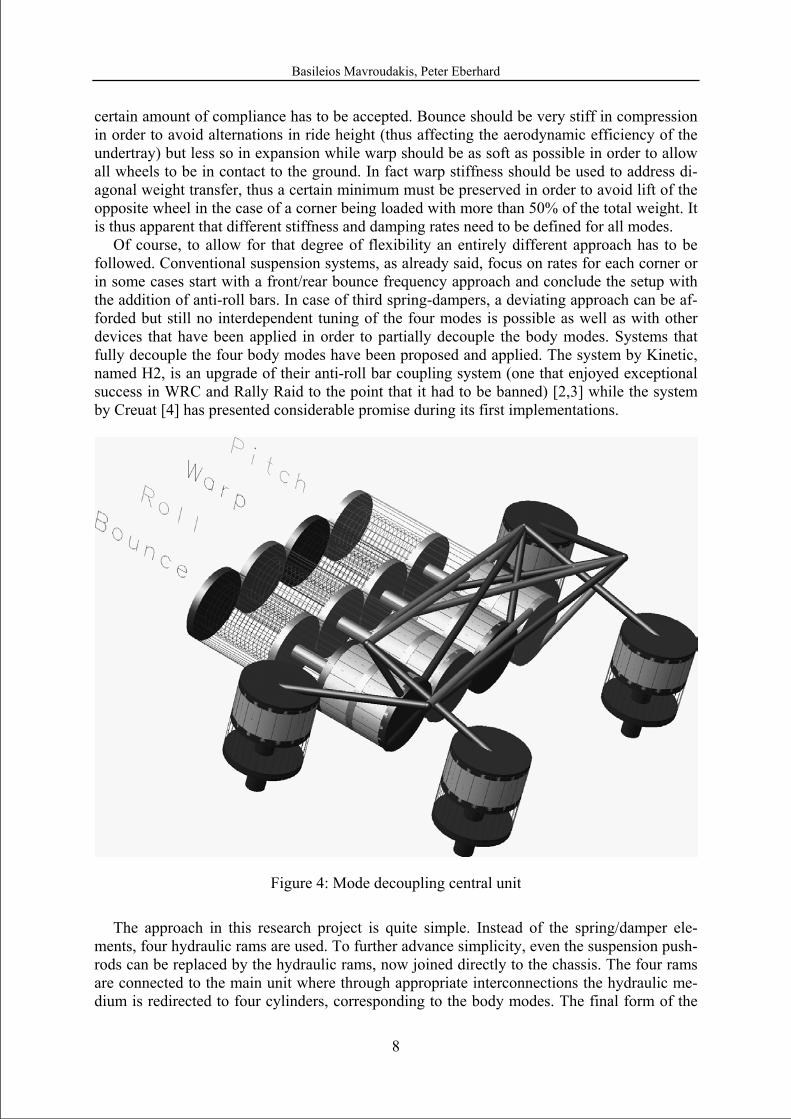
Figure 4: Mode decoupling central unit
The approach in this research project is quite simple. Instead of the spring/damper ele-
ments, four hydraulic rams are used. To further advance simplicity, even the suspension push-rods can be replaced by the hydraulic rams, now joined directly to the chassis. The four rams are connected to the main unit where through appropriate interconnections the hydraulic me-dium is redirected to four cylinders, corresponding to the body modes. The final form of the
Basileios Mavroudakis, Peter Eberhard
9
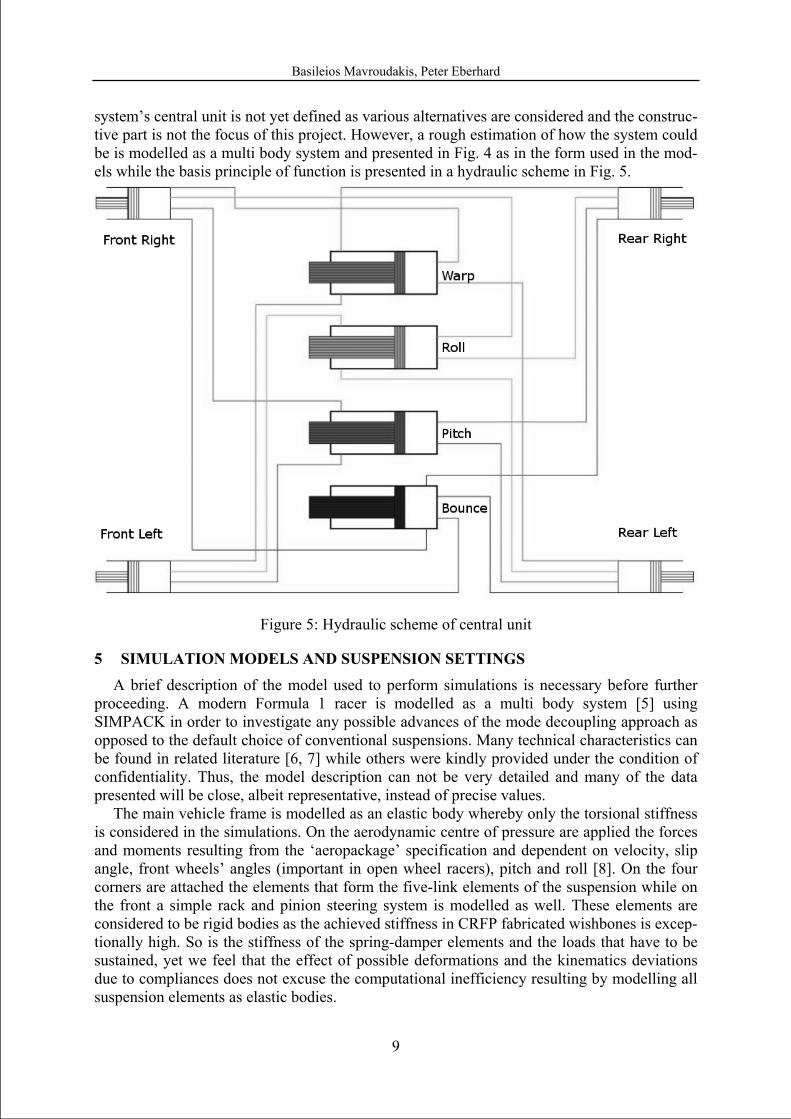
system’s central unit is not yet defined as various alternatives are considered and the construc-tive part is not the focus of this project. However, a rough estimation of how the system could be is modelled as a multi body system and presented in Fig. 4 as in the form used in the mod-els while the basis principle of function is presented in a hydraulic scheme in Fig. 5.
Figure 5: Hydraulic scheme of central unit
5 SIMULATION MODELS AND SUSPENSION SETTINGS
A brief description of the model used to perform simulations is necessary before further proceeding. A modern Formula 1 racer is modelled as a multi body system [5] using SIMPACK in order to investigate any possible advances of the mode decoupling approach as opposed to the default choice of conventional suspensions. Many technical characteristics can be found in related literature [6, 7] while others were kindly provided under the condition of confidentiality. Thus, the model description can not be very detailed and many of the data presented will be close, albeit representative, instead of precise values.
The main vehicle frame is modelled as an elastic body whereby only the torsional stiffness is considered in the simulations. On the aerodynamic centre of pressure are applied the forces and moments resulting from the ‘aeropackage’ specification and dependent on velocity, slip angle, front wheels’ angles (important in open wheel racers), pitch and roll [8]. On the four corners are attached the elements that form the five-link elements of the suspension while on the front a simple rack and pinion steering system is modelled as well. These elements are considered to be rigid bodies as the achieved stiffness in CRFP fabricated wishbones is excep-tionally high. So is the stiffness of the spring-damper elements and the loads that have to be sustained, yet we feel that the effect of possible deformations and the kinematics deviations due to compliances does not excuse the computational inefficiency resulting by modelling all suspension elements as elastic bodies.
Basileios Mavroudakis, Peter Eberhard
10
The control systems used regard longitudinal and lateral control. A PID controller is used for the former whereby the desired velocity at various positions on the followed trajectory is provided as input. The power curve characteristics of a 3 litre V-10 motor are provided as a limit to the available thrust for every combination of gear and motor rpm while the gearbox is modelled as a controlled unit with the ability to imply torque deviations in order to aid trac-tion. The brake system is modelled in a slightly more detailed manner (considering actual constructive elements, e.g. brake disc inertial characteristics) and is controlled by the same controlled system. Here it should be noted that, as any type of anti-block system is prohibited, some possible ways of avoiding wheel lock under braking were investigated and a particular type of viscous differential proved to be quite effective while still complying with the present rules. Lateral control is similarly applied through a PID controller whereby the trajectory is given as a function (e.g. the actual trajectory is derived from track measurements) that has to be precisely followed by the driver. In order to achieve this target, the controller is velocity dependent both in terms of gain factors and preview length. It is needless to add that in both cases, realistic driver characteristics are specified for the controllers in order to comply with human reaction times and not to exceed the ability of an actual pilot. A final detail that further enhances the realistic behaviour of the control system is the coupling of longitudinal and lat-eral dynamics. As in reality, the control system applies thrust or brake torque to moderate the dynamic balance of the vehicle from understeer to oversteer and vice versa, a technique widely used by experienced drivers.
Last, but certainly not least, the tire models. The simulation program used offers an exten-sive library of tire models to be used. Two models have been applied, based on the Pacejka Magic Formula [9] and the SWIFT tire model as provided by TNO with the parameters prop-erly tuned so that the tire characteristics match the performance expected by tires of slick specification as used on a dry track.
The conventional suspension stiffness is tuned in order to withstand the vertical loads of aerodynamic downforce without significant alternations in ride height through the operation velocity range of the vehicle while the anti-roll bars are used to provide the desirable roll stiffness to the vehicle and tune the handling balance, slightly understeering in this case. The definition of damping ratios is performed in a similar way to the guidelines provided in [10, 11] so that the final correlations result in optimal performance through the simulated handling manoeuvres. It has to be noted that the final set-up results in slightly higher rear bounce fre-quency (expected due to the higher downforce applied to the rear axis) while the modes of group c) are overdamped [12]. Naturally, the modes of group b) are slightly damped as in an in-series spring connection whereby only one of the elements can be damped; there is an up-per limit of total damping that can be achieved
The mode decoupling system is tuned in a different manner. The contribution of the front and rear hydraulic rams to each of the four cylinders, responsible for suspending the respec-tive mode, is regulated so that it is either balanced with respect to the loads it is expected to absorb or biased towards the desirable ratio of stiffness distribution. Thus, the bounce mode and pitch mode are balanced with respect to the massive aerodynamic loads whereas the roll and warp mode with respect to the desirable roll stiffness and the diagonal weight transfer. The bounce stiffness is also set rather high and progressively rising in compression so that the aerodynamic loads do not significantly alter the vehicle ride height while the pitch stiffness is also stiff and progressive in order to restrain the pitch angle variations under longitudinal ac-celerations but also to absorb sinusoidal road irregularities that excite the pitch mode. The roll mode has been found to be quite effective when it presents a frequency similar to the yaw fre-quency as defined by the tire lateral stiffness, wheelbase and weight distribution. Finally the warp stiffness is set low in comparison to the rest (and very low in comparison to a conven-
Basileios Mavroudakis, Peter Eberhard
11
tional race car) in order to allow all wheels being in contact to the track in uneven parts and also withstand single wheel excitations such as bumps or riding over kerbs. The damping rates were successively defined in order to achieve critical damping for the modes of group c), a set-up which also resulted in the highest possible damping ratio for the modes of group b) as well. Thus, the overall body movement with respect to the ground was minimized as were the wheel centre accelerations ensuring maximum tire loading balance.
6 HANDLING MANOUEVRES AND SIMULATION RESULTS The closest stage to actual track testing is either the use of a seven-post rig or the simula-
tion of handling manoeuvres, when properly executed. These will be the basis for our conclu-sions as physical prototypes of the system are not yet build. Considering the satisfactory detailing of the vehicle and driver modelling, the remaining factor is the definition of realistic track conditions in order to validate the system’s potential. Simulations of both models are performed under the same conditions, meaning that apart from the suspension systems, the models are physically identical and tested with the same velocity objectives in all but one track section.
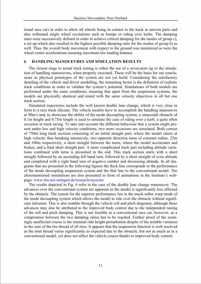
Simulated trajectories include the well known double lane change, which is very close in form to a race track chicane. The vehicle models have to accomplish the handling manoeuvre at 90m/s and, to showcase the ability of the mode decoupling system, a sinusoidal obstacle of 0.1m height and 0.75m length is used to simulate the case of riding over a kerb, a quite often occasion in track racing. To take into account the different behaviour that a system might pre-sent under low and high velocity conditions, two more occasions are simulated. Both consist of 750m long track sections consisting of an initial straight part, where the model enters at high velocity thus breaking intensively, two opposite direction turns of constant radius, 25m and 100m respectively, a short straight between the turns, where the model accelerates and brakes, and a final short straight part. A more complicated track part including altitude varia-tions combined with turns is presented in the end. This track section starts with a short straight followed by an ascending left hand turn, followed by a short straight of even altitude and completed with a right hand turn of negative camber and decreasing altitude. In all dia-grams that are presented in the following figures the thick line corresponds to the performance of the mode decoupling suspension system and the thin line to the conventional model. The aforementioned simulations are also presented in form of animations in the Institute’s web-page: www.itm.uni-stuttgart.de/research/racecars
The results depicted in Fig. 6 refer to the case of the double lane change manoeuvre. The advances over the conventional system are apparent as the model is significantly less affected by the obstacle. The reason for the superior performance lies in the much softer warp mode of the mode decoupling system which allows the model to ride over the obstacle without signifi-cant intrusion. This is also notable through the vehicle roll and pitch diagrams, although these advances may also be attributed to the improved body control due to the independent tuning of the roll and pitch damping. This is not feasible in a conventional race car, however, as a compromise between the two damping ratios has to be reached. Further proof of the seem-ingly unaffected course is the minimal ride height perturbation despite of the notable variation in the sum of the tire thread of all tires. It appears that the suspension function is well resolved as the total thread varies significantly as expected due to the obstacle, but not as much as in a conventional model, yet does not affect the vehicle course thanks to improved body control.
Basileios Mavroudakis, Peter Eberhard
12
0 1 2 3
−0.01
0
0.01
vehicle pitch anglean
gle
[ra
d]
time [sec]0 1 2 3
−0.1
−0.05
0
0.05
vehicle roll angle
angl
e [
rad]
time [sec]
0 1 2 30.25
0.3
0.35
0.4
ride height, centre of gravity
heig
ht [
m]
time [sec]0 1 2 3 4
0
0.5
1
1.5thread length
leng
th [
m]
time [sec]
Figure 6: Double lane change
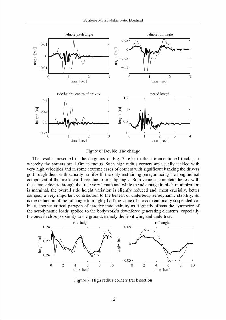
The results presented in the diagrams of Fig. 7 refer to the aforementioned track part whereby the corners are 100m in radius. Such high-radius corners are usually tackled with very high velocities and in some extreme cases of corners with significant banking the drivers go through them with actually no lift-off, the only restraining paragon being the longitudinal component of the tire lateral force due to tire slip angle. Both vehicles complete the test with the same velocity through the trajectory length and while the advantage in pitch minimization is marginal, the overall ride height variation is slightly reduced and, most crucially, better damped, a very important contribution to the benefit of underbody aerodynamic stability. So is the reduction of the roll angle to roughly half the value of the conventionally suspended ve-hicle, another critical paragon of aerodynamic stability as it greatly affects the symmetry of the aerodynamic loads applied to the bodywork’s downforce generating elements, especially the ones in close proximity to the ground, namely the front wing and undertray.
0 2 4 6 8 10
0.26
0.27
0.28ride height
heig
ht [
m]
time [sec]0 2 4 6 8 10
−0.05
0
0.05roll angle
angl
e [
m]
time [sec]
Figure 7: High radius corners track section
Basileios Mavroudakis, Peter Eberhard
13
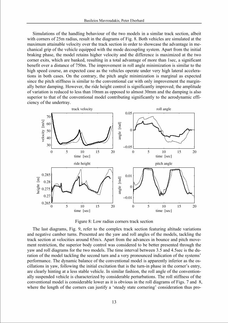
Simulations of the handling behaviour of the two models in a similar track section, albeit with corners of 25m radius, result in the diagrams of Fig. 8. Both vehicles are simulated at the maximum attainable velocity over the track section in order to showcase the advantage in me-chanical grip of the vehicle equipped with the mode decoupling system. Apart from the initial braking phase, the model retains higher velocity and the difference is maximized at the two corner exits, which are banked, resulting in a total advantage of more than 1sec, a significant benefit over a distance of 750m. The improvement in roll angle minimization is similar to the high speed course, an expected case as the vehicles operate under very high lateral accelera-tions in both cases. On the contrary, the pitch angle minimization is marginal as expected since the pitch stiffness is similar to the conventional car with only improvement the margin-ally better damping. However, the ride height control is significantly improved; the amplitude of variation is reduced to less than 10mm as opposed to almost 30mm and the damping is also superior to that of the conventional model contributing significantly to the aerodynamic effi-ciency of the undertray.
0 5 10 15 20
30
40
50
60
70
track velocity
velo
city
[m
/s]
time [sec]0 5 10 15 20
−0.05
0
0.05roll angle
angl
e [
rad]
time [sec]
0 5 10 15 200.265
0.27
0.275
0.28
0.285
ride height
heig
ht [
m]
time [sec]0 5 10 15 20
−0.01
0
0.01
pitch angle
angl
e [
rad]
time [sec]
Figure 8: Low radius corners track section
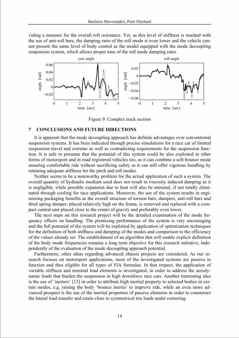
The last diagrams, Fig. 9, refer to the complex track section featuring altitude variations and negative camber turns. Presented are the yaw and roll angles of the models, tackling the track section at velocities around 65m/s. Apart from the advances in bounce and pitch move-ment restriction, the superior body control was considered to be better presented through the yaw and roll diagrams for the two models. The time interval between 3.5 and 4.5sec is the du-ration of the model tackling the second turn and a very pronounced indication of the systems’ performance. The dynamic balance of the conventional model is apparently inferior as the os-cillations in yaw, following the initial excitation that is the turn-in phase in the corner’s entry, are clearly hinting at a less stable vehicle. In similar fashion, the roll angle of the convention-ally suspended vehicle is characterized by considerable perturbations. The roll stiffness of the conventional model is considerable lower as it is obvious in the roll diagrams of Figs. 7 and 8, where the length of the corners can justify a ‘steady state cornering’ consideration thus pro-
Basileios Mavroudakis, Peter Eberhard
14
viding a measure for the overall roll resistance. Yet, as this level of stiffness is reached with the use of anti-roll bars, the damping ratio of the roll mode is even lower and the vehicle can-not present the same level of body control as the model equipped with the mode decoupling suspension system, which allows proper tune of the roll mode damping ratio.
0 1 2 3 4 5
−0.02
0
0.02
0.04
0.06
yaw angle
angl
e [
rad]
time [sec]0 1 2 3 4 5
−0.06
−0.04
−0.02
0
0.02
roll angle
angl
e [
rad]
time [sec]
Figure 9: Complex track section
7 CONCLUSIONS AND FUTURE DIRECTIONS It is apparent that the mode decoupling approach has definite advantages over conventional
suspension systems. It has been indicated through precise simulations for a race car of limited suspension travel and extreme as well as contradicting requirements for the suspension func-tion. It is safe to presume that the potential of this system could be also exploited in other forms of motorsport and in road registered vehicles too, as it can combine a soft bounce mode ensuring comfortable ride without sacrificing safety as it can still offer vigorous handling by retaining adequate stiffness for the pitch and roll modes.
Neither seems to be a noteworthy problem for the actual application of such a system. The overall quantity of hydraulic medium used does not result in viscosity induced damping as it is negligible, while possible expansion due to heat will also be minimal, if not totally elimi-nated through cooling for race applications. Moreover, the use of the system results in engi-neering packaging benefits as the overall structure of torsion bars, dampers, anti-roll bars and third spring damper, placed relatively high on the frame, is removed and replaced with a com-pact central unit placed close to the centre of gravity and preferably even lower.
The next steps on this research project will be the detailed examination of the mode fre-quency effects on handling. The promising performance of the system is very encouraging and the full potential of the system will be exploited by application of optimization techniques for the definition of both stiffness and damping of the modes and comparison to the efficiency of the values already set. The establishment of an algorithm that will enable explicit definition of the body mode frequencies remains a long term objective for this research initiative, inde-pendently of the evaluation of the mode decoupling approach potential.
Furthermore, other ideas regarding advanced chassis projects are considered. As our re-search focuses on motorsport applications, most of the investigated systems are passive in function and thus eligible for all types of FIA formulae. In that respect, the application of variable stiffness and nominal load elements is investigated, in order to address the aerody-namic loads that burden the suspension in high downforce race cars. Another interesting idea is the use of ‘inerters’ [13] in order to attribute high inertial property to selected bodies in cer-tain modes, e.g. raising the body ‘bounce inertia’ to improve ride, while an even more ad-vanced prospect is the use of the inertial properties of passive elements in order to counteract the lateral load transfer and retain close to symmetrical tire loads under cornering.
Basileios Mavroudakis, Peter Eberhard
15
ACKNOWLEGDEMENTS The authors would like to acknowledge the help and valuable comments of Prof. W.
Schiehlen, University of Stuttgart, on many topics related to this project.
REFERENCES [1] P. Wright, Formula 1 Technology. SAE International, Warrendale, 2001
[2] J.R. Wilde, G.J. Heydinger, D.A. Guenther, ADAMS Simulation of Ride and Han-dling Performance of Kinetic Suspension System. SAE 2006 Automotive Dynamics, Stability and Controls Conference and Exhibition, February 2006, Novi, MI, USA
[3] J.R. Wilde, G.J. Heydinger, D.A. Guenther, T.P. Mallin, A.M. Devenish, Experimen-tal Evaluation of Fishhook Maneuver Performance of a KineticSt Suspension System. SAE 2005 World Congress & Exhibition, April 2005, Detroit, MI, USA
[4] J. Fontdecaba – CREUAT S. L., Integral Suspension System for Motor Vehicles Based on Passive Components. International Truck & Bus Meeting & Exhibition, No-vember 2002, Detroit, MI, USA
[5] W. Schiehlen, Multibody system dynamics: Roots and perspectives. Multibody System Dynamics, 1, 149–188, 1997
[6] P. Wright, Ferrari Formula 1. SAE International, Warrendale, 2005
[7] D. Casanova, R.S. Sharp, P. Symonds, Minimum Time Manoeuvring: The Signifi-cance of Yaw Inertia. Vehicle System Dynamics, Vol. 34 (2), 77-115, 2000
[8] G. Genta, Motor Vehicle Dynamics. Series on Advaances in Mathemaatics for Applied Sciences- Vol. 43, World Scientific Publishing, Singapore,1997
[9] H.B. Pacejka, Tyre and Vehicle Dynamics. Butterworth Heinemann, Oxford, 2002
[10] J.E. Kelly, H. Kowalczyk, H.A. Oral, Track Simulation and Vehicle Characterization With 7 Post Testing. Motorsports Engineering Conference & Exhibition, December 2002, Indianapolis, IN, USA
[11] H.R. Kowalczyk, Damper Tuning with the Use of a Seven Post Shaker Rig. SAE 2002 World Congress & Exhibition, March 2002, Detroit, MI, USA
[12] W.F. Milliken, D.L. Milliken, Race Car Vehicle Dynamics. SAE International, Warrendale, 1995
[13] M.C. Smith, F.C. Wang, Performance Benefits in Passive Vehicle Suspensions Em-ploying Inerters. Vehicle System Dynamics, Vol. 42 (4), 235-257, October 2004