Embed Size (px)
Citation preview

Publication PUB059-003-00 Issue 01/15
Modbus RTU Serial and TCP/IP Communication Specification for
Pakscan P3 and P3F Master Station

Pakscan P3 with P720 Module Modbus Interface Specification
2 of 96 Publication PUB059-003-00 Issue 01/15
As we are continually developing our products their design is subject to change without notice.
© The contents of this document are copyright and must not be reproduced without the written
permission of Rotork Controls Ltd. The name Rotork is a registered trademark Modbus is a registered trademark of Modbus-IDA Centum is a registered trademark by Yokogawa Electric Corporation EPLCG, SI gateway, TDC3000, Experion are products of Honeywell Inc.
Contents
Issue 01/15 Publication PUB059-003-00 3 of 96
Contents
Glossary of Terms: ............................................................................................................................ 5
Abbreviations: ................................................................................................................................... 5
1 INTRODUCTION ................................................................................................. 7
1.1 General ..................................................................................................................................... 8
1.2 Serial communication to Pakscan master stations ............................................................. 8 1.2.1 Serial communication to a Pakscan P3F master station ...................................... 9 1.2.2 Serial communication to a P3 master station .....................................................10 1.2.3 Host communication connections for hot standby P3 master stations ...............11 1.2.4 P3 master station – Port Function ......................................................................15 1.2.5 P3 master station – RS485 termination ..............................................................15 1.2.6 P3 master station – RS485 Cross Connection (Hot Standby Systems).............16 1.2.7 RS485 termination – Pakscan P3F master station.............................................16
1.3 Ethernet Communications to Pakscan master stations ...................................................17 1.3.1 Ethernet Connection ...........................................................................................17
2 DATA INTERPRETATION ................................................................................ 19
2.1 Master station data ...............................................................................................................19 2.1.1 Data base segregation .......................................................................................19 2.1.2 Master station data description...........................................................................20 2.1.3 Alarm handling ....................................................................................................21 2.1.4 Data relevant to hot standby systems ................................................................21 2.1.5 Additional data available using Generic / EPLCG Interface ...............................22 2.1.6 Command description .........................................................................................23
2.2 Field unit data ........................................................................................................................24 2.2.1 Digital status bits ................................................................................................24 2.2.2 Alarm data bits ....................................................................................................25 2.2.3 Field unit commands ..........................................................................................25 2.2.4 Field unit analogue inputs ...................................................................................26
3 MODBUS SPECIFICATION.............................................................................. 27
3.1 Electrical specification .........................................................................................................27
3.2 Outer protocol .......................................................................................................................27
3.3 Serial Data ..............................................................................................................................27
3.4 Overview of the design .........................................................................................................27
4 GENERIC AND HONEYWELL EPLCG PROTOCOL INTERFACE SPECIFICATION .............................................................................................. 29
4.1 Modbus unit address (Generic and Honeywell EPLCG protocols) ..................................29
4.2 Modbus function code support (Generic and Honeywell EPLCG protocols) .................31
4.3 Data base access (Generic and Honeywell EPLCG protocols) ........................................34 4.3.1 Data Organisation ...............................................................................................34 4.3.2 Data Read Requests ..........................................................................................34 4.3.3 Register and Discrete Address Formulae ..........................................................35
Pakscan P3 with P720 Module Modbus Interface Specification
4 of 96 Publication PUB059-003-00 Issue 01/15
4.4 Notes on the use of the Generic and EPLCG Modbus protocol.......................................38 4.4.1 Suggested Scan Cycle .......................................................................................38 4.4.2 Writing to Coils....................................................................................................38 4.4.3 Readback of Holding Registers ..........................................................................39 4.4.4 Alarm Handling ...................................................................................................39 4.4.5 Use of Alarm Bits ................................................................................................40
4.5 Master station data base (Generic and Honeywell EPLCG protocols) ............................41 4.5.1 Master Station Read Only Data ..........................................................................41 4.5.2 Master Station Write Only Data ..........................................................................44
4.6 Field unit data base (Generic and Honeywell EPLCG protocols) ....................................45 4.6.1 Field Unit Data Base Locations ..........................................................................46
4.7 Modbus messages examples (Generic and Honeywell EPLCG protocols) ....................55 4.7.1 Read Master Station Status ................................................................................55 4.7.2 Write Master Station Alarm Accept ....................................................................55 4.7.3 Read Field Unit 12 Digital Status........................................................................55 4.7.4 Read Field Unit 62 Digital Status........................................................................56 4.7.5 Read Digital Status from 60 Field Units, Addresses 121 to 180 ........................56 4.7.6 Energise Command to OPEN relay of Field Unit 4 ............................................56 4.7.7 Write Desired Valve Position for FCU 26 to be 50% ..........................................56
5 YOKOGAWA AND HONEYWELL SI PROTOCOL INTERFACE SPECIFICATION .............................................................................................. 57
5.1 Modbus unit address (Yokogawa and Honeywell SI protocols) ......................................57
5.2 Modbus function code support (Yokogawa and Honeywell SI protocols) ......................59
5.3 Data base access (Yokogawa and Honeywell SI protocols).............................................62 5.3.1 Data Organisation ...............................................................................................62 5.3.2 Data Interchange Requests ................................................................................62
5.4 Notes on the use of the Yokogawa and Honeywell SI Modbus protocol ........................62 5.4.1 Suggested Scan Cycle .......................................................................................63 5.4.2 Writing to Coils....................................................................................................63 5.4.3 Readback of Holding Registers ..........................................................................63 5.4.4 Alarm Handling ...................................................................................................64 5.4.5 Use of Alarm Bits ................................................................................................65
5.5 Master station data base (Yokogawa and Honeywell SI protocols) ................................66 5.5.1 Master Station Records ......................................................................................66
5.6 Field unit data base (Yokogawa and Honeywell SI protocols) .........................................67 5.6.1 Digital Inputs (Field Units) ..................................................................................67 5.6.2 Digital Outputs (Field Units) ................................................................................73 5.6.3 Analogue Inputs (Field Units) .............................................................................75 5.6.4 Analogue Outputs (Field Units) ..........................................................................78
5.7 Field unit inputs and outputs available ..............................................................................79 5.7.1 Digital Inputs .......................................................................................................79 5.7.2 Digital Outputs ....................................................................................................81 5.7.3 Analogue Inputs ..................................................................................................81 5.7.4 Analogue Outputs ...............................................................................................81
5.8 Modbus message examples (Yokogawa and Honeywell SI protocols) ...........................82 5.8.1 Read Field Unit Bit 5 from FCU 1 to 100 ............................................................82 5.8.2 Read Field Unit Bit 2 and 3 from FCU 1 to 120 ..................................................82

Contents
Issue 01/15 Publication PUB059-003-00 5 of 96
5.8.3 Read Valve Position from FCU 26......................................................................82 5.8.4 Energise Command to Open relay of Field Unit 104 ..........................................82 5.8.5 Write Desired Valve Position for FCU 26 to be 50% ..........................................83
6 FIELD UNIT BLOCK AND PARAMETER ALLOCATIONS.............................. 85
6.1 Block and parameter construction ......................................................................................85 6.1.1 Digital inputs .......................................................................................................85 6.1.2 Alarm block .........................................................................................................85 6.1.3 Analogue and counter input data........................................................................85 6.1.4 Outputs ...............................................................................................................86
6.2 Block and parameter usage .................................................................................................86
Glossary of Terms:
Block A master station data base entry covering 8 related parameters Parameter A master station data base entry of 16 bits Bit A master station data base discrete entry. Modbus Address The 8 bit address to which a Modbus Slave responds when interrogated. Register Address A data base start location within a Modbus address used to access at least
one parameter (16 bits). Discrete Address A data base start location within a Modbus address used to access at least
one bit. Field Unit A device connected to a master station that reports records into the master
station data base. Master Station A Modbus slave containing a data base about itself and the connected field
units. Slave A Modbus device containing data. Host A Modbus master controlling all data transactions on the Data Highway. Data Highway The mechanism along which the data flows; e.g. the RS 232, RS485 or
Ethernet connection between Host and master station(s). Gateway The host device (PLC or DCS or other equipment) interface to the data
highway Pakscan 3 Generic term for a P3 or P3F master station controlled system P3 master station Refers to the rack or panel mounted version of the master station, single
dual or Hot standby P3F master station Refers to the field mountable version of the master station
Abbreviations:
Comms Communications CRC Cyclic Redundancy Check DIP Dual In-Line Package (chip) FCU Field Unit FU Field Unit HW Hardware MS Master Station No Number RAM Random Access Memory ROM Read Only Memory RTU Remote Terminal Unit SW Software

Pakscan P3 with P720 Module Modbus Interface Specification
6 of 96 Publication PUB059-003-00 Issue 01/15
(This page is intentionally blank)
Serial Communications
Issue 01/15 Publication PUB059-003-00 7 of 96
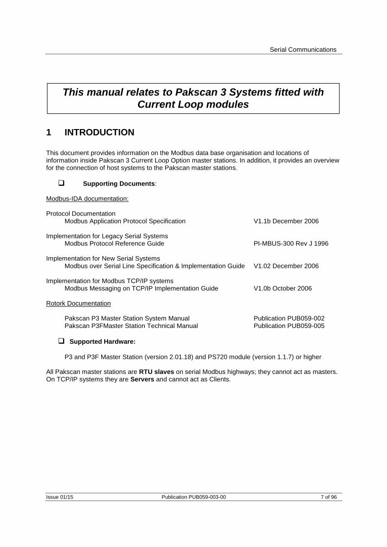
1 INTRODUCTION
This document provides information on the Modbus data base organisation and locations of information inside Pakscan 3 Current Loop Option master stations. In addition, it provides an overview for the connection of host systems to the Pakscan master stations.
Supporting Documents: Modbus-IDA documentation: Protocol Documentation Modbus Application Protocol Specification V1.1b December 2006 Implementation for Legacy Serial Systems Modbus Protocol Reference Guide PI-MBUS-300 Rev J 1996 Implementation for New Serial Systems Modbus over Serial Line Specification & Implementation Guide V1.02 December 2006 Implementation for Modbus TCP/IP systems Modbus Messaging on TCP/IP Implementation Guide V1.0b October 2006 Rotork Documentation Pakscan P3 Master Station System Manual Publication PUB059-002 Pakscan P3FMaster Station Technical Manual Publication PUB059-005
Supported Hardware:
P3 and P3F Master Station (version 2.01.18) and PS720 module (version 1.1.7) or higher All Pakscan master stations are RTU slaves on serial Modbus highways; they cannot act as masters. On TCP/IP systems they are Servers and cannot act as Clients.
This manual relates to Pakscan 3 Systems fitted with
Current Loop modules

Pakscan P3 with P720 Module Modbus Interface Specification
8 of 96 Publication PUB059-003-00 Issue 01/15
1.1 General
All Pakscan master stations are supplied preconfigured with a standard, non-variable, data base relating to the field units connected. The data is always as listed in this document and does not vary between projects. Because various host systems have complexities and requirements that are slightly different there are two basic data base maps, each with two variations on analogue register value scaling. The data base organisation that is accessed is chosen by the user. It is selected from the list of four by entering the choice into the system using the keypad and LCD screen on the master station. At any time the choice can be amended and no additional re-programming of the unit is required.
1.2 Serial communication to Pakscan master stations
All Pakscan master stations have two or more serial communication ports available for connection to host systems. These may be either RS232 or RS485 depending on the options specified when the unit was manufactured. It is possible to retrospectively change these ports after delivery by altering the DIP switches on the backplane of either unit. In all cases, the communication is half-duplex and in the case of RS485 it is 2-wire.
Fig 1: Pakscan P3 and Pakscan P3F master station
Serial Communications
Issue 01/15 Publication PUB059-003-00 9 of 96
PLC Pakscan P3F Master Station
Pakscan P 3
rotork P 3 F
Highway 1
Highway 2
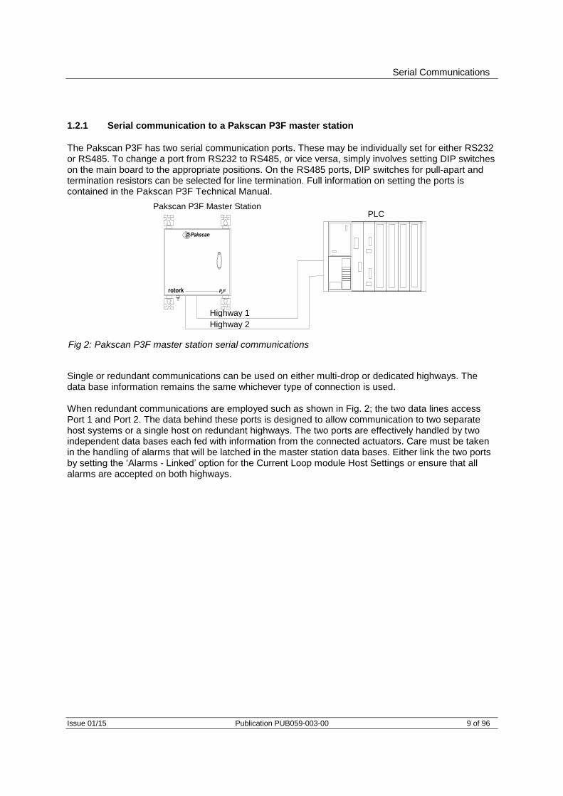
1.2.1 Serial communication to a Pakscan P3F master station
The Pakscan P3F has two serial communication ports. These may be individually set for either RS232 or RS485. To change a port from RS232 to RS485, or vice versa, simply involves setting DIP switches on the main board to the appropriate positions. On the RS485 ports, DIP switches for pull-apart and termination resistors can be selected for line termination. Full information on setting the ports is contained in the Pakscan P3F Technical Manual.
Single or redundant communications can be used on either multi-drop or dedicated highways. The data base information remains the same whichever type of connection is used. When redundant communications are employed such as shown in Fig. 2; the two data lines access Port 1 and Port 2. The data behind these ports is designed to allow communication to two separate host systems or a single host on redundant highways. The two ports are effectively handled by two independent data bases each fed with information from the connected actuators. Care must be taken in the handling of alarms that will be latched in the master station data bases. Either link the two ports by setting the ‘Alarms - Linked’ option for the Current Loop module Host Settings or ensure that all alarms are accepted on both highways.
Fig 2: Pakscan P3F master station serial communications
Pakscan P3 with P720 Module Modbus Interface Specification
10 of 96 Publication PUB059-003-00 Issue 01/15
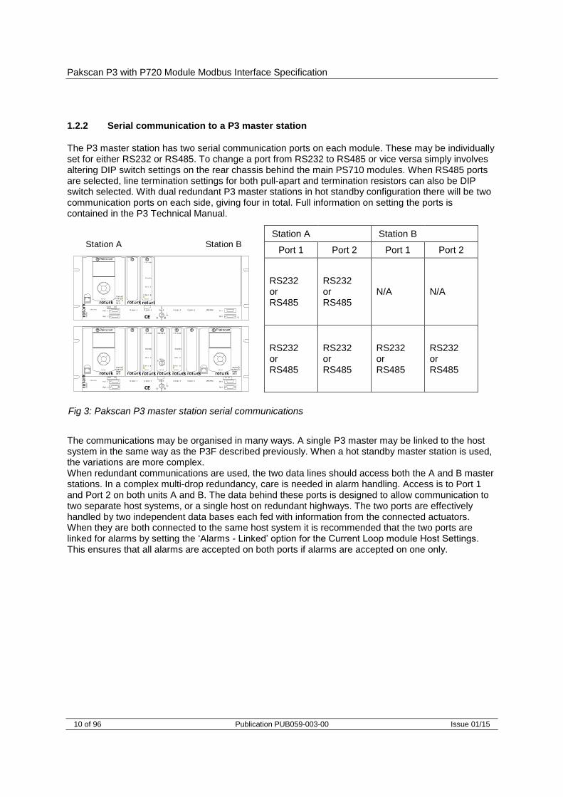
1.2.2 Serial communication to a P3 master station
The P3 master station has two serial communication ports on each module. These may be individually set for either RS232 or RS485. To change a port from RS232 to RS485 or vice versa simply involves altering DIP switch settings on the rear chassis behind the main PS710 modules. When RS485 ports are selected, line termination settings for both pull-apart and termination resistors can also be DIP switch selected. With dual redundant P3 master stations in hot standby configuration there will be two communication ports on each side, giving four in total. Full information on setting the ports is contained in the P3 Technical Manual.
The communications may be organised in many ways. A single P3 master may be linked to the host system in the same way as the P3F described previously. When a hot standby master station is used, the variations are more complex. When redundant communications are used, the two data lines should access both the A and B master stations. In a complex multi-drop redundancy, care is needed in alarm handling. Access is to Port 1 and Port 2 on both units A and B. The data behind these ports is designed to allow communication to two separate host systems, or a single host on redundant highways. The two ports are effectively handled by two independent data bases each fed with information from the connected actuators. When they are both connected to the same host system it is recommended that the two ports are linked for alarms by setting the ‘Alarms - Linked’ option for the Current Loop module Host Settings. This ensures that all alarms are accepted on both ports if alarms are accepted on one only.
Fig 3: Pakscan P3 master station serial communications
Por t 1
Por t 2
P3
PS7 30
Key swit ch
Aut oA B
P3 P3
PS7 20
I I E L o op
St a nd b y
Por t A
Por t B
P3
PS7 20
I I E L o op
St a nd b y
Por t A
Por t B
P3
PS7 10
P akscanP3
St at usPr i/ St by
PowerAlar m
PS7
00
CPU/ PSUPor t 1
Por t 2
PS7 10
PakscanP3
St at usPr i/ St by
PowerAlar m
O pt ion 1 O pt ion 2 Swit ch
A BCE
O pt ion 2 O pt ion 1 CPU/ PSU
roto
rk
rotork rotork rotork rotork rotork rotork rotork
Por t 1
Por t 2
P3
PS7 30
Keyswit ch
Aut oA B
P3 P3
PS7 20
I I E Loop
St andby
Por t A
Por t B
P3
PS7 20
I I E Loop
St andby
Por t A
Por t B
P3
PS7 10
P akscanP3
St at usPr i/ St byPowerAlar m
PS7
00
CPU/ PSUPor t 1
Por t 2
PS7 10
PakscanP3
St at usPr i/ St byPowerAlar m
O pt ion 1 O pt ion 2 Swit ch
A BCE
O pt ion 2 O pt ion 1 CPU/ PSU
roto
rk
rotork rotork rotork rotork rotork rotork rotork
Station A Station BStation A Station B
Port 1 Port 2 Port 1 Port 2
RS232 or RS485
RS232 or RS485
N/A N/A
RS232 or RS485
RS232 or RS485
RS232 or RS485
RS232 or RS485

Serial Communications
Issue 01/15 Publication PUB059-003-00 11 of 96
1.2.3 Host communication connections for hot standby P3 master stations
The P3 hot standby system has two master stations operating one field network or Pakscan 2-wire current loop. One master station PS710 module will be the main or primary unit controlling the network and the other will be the standby unit monitoring the performance of the main unit. Either unit can be in either mode although they cannot both be in the same mode, i.e. either master station A or master station B can be the main or primary unit whilst the other is in standby mode. Each module has two communication ports as described above. The configuration option for hot standby mode includes a choice for host communications, i.e. ‘Active’ or ‘Passive’ when the module is in Standby mode. This is a selection for the communications option of the PS710 module itself, rather than the hot standby pair (the setting is located in the M/S Settings menu page). The choice determines how the module responds to host communications when it is in standby mode, and each module has a separate choice for both of its host ports. If the module is set to ‘Passive’, it will not respond to messages from the host when it is the standby unit, however, it will reply when it is the main unit. When the unit is the main module, it will always respond to all instructions. When the module is set to ‘Active’, it will respond to messages from the host irrespective of whether it is in main or standby mode. When ‘Active’ is selected, care must be taken to ensure that valve commands are addressed to the module that is in main mode as the module in standby mode is prevented from controlling the field network or Pakscan current loop. It is also important to note how control passes from one module to the other. The command to change master will reverse the mode of the two units and the instruction can be instigated either from the keypad or via the serial communications link. Note that it is the only command actioned by a standby unit which is set to ‘Passive’. (The keyswitch can also be used to make either station A or station B the main module). A standby unit will change automatically to the main unit when it detects that its partner has failed or that it no longer has control.
Station in Primary/Main Mode
Station in Standby Mode Comms port set Active
Station in Standby Mode Comms port set Passive
Controls the field network and 2-wire current loop
Does not control the field network and 2-wire current loop
Does not control the field network and 2-wire current loop
Responds to all host messages and actions all commands
Responds to all host messages, does not action any commands
Does not respond to any host messages, only actions a change-over command
May be remotely commanded to change to standby mode
May be remotely commanded to change to main mode
May be remotely commanded to change to main mode
Pakscan P3 with P720 Module Modbus Interface Specification
12 of 96 Publication PUB059-003-00 Issue 01/15
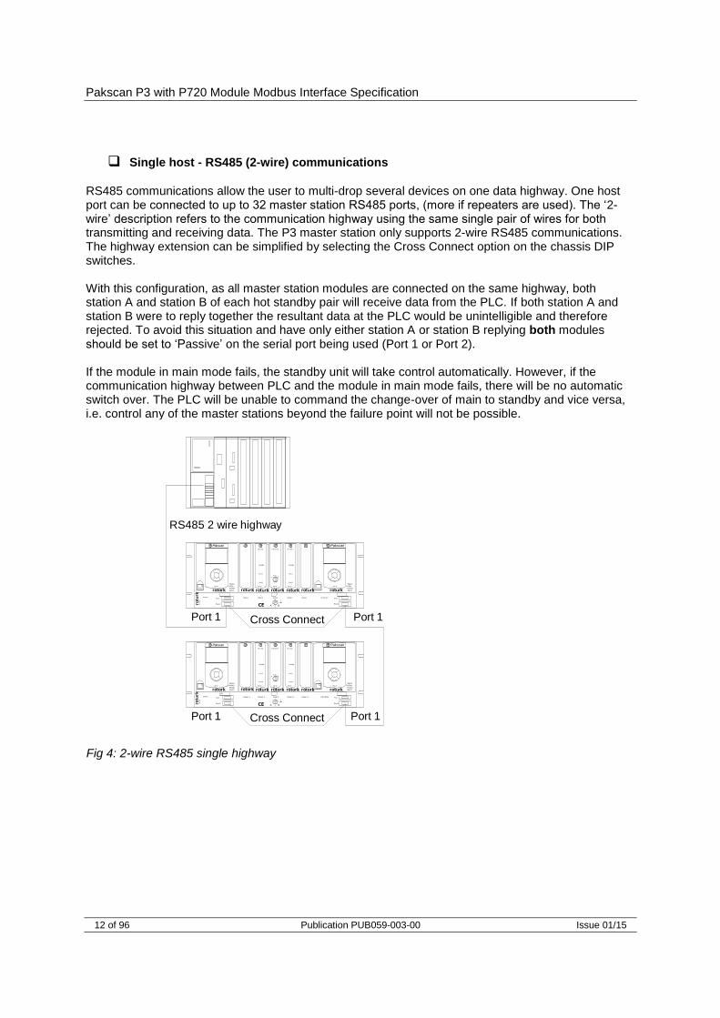
Single host - RS485 (2-wire) communications
RS485 communications allow the user to multi-drop several devices on one data highway. One host port can be connected to up to 32 master station RS485 ports, (more if repeaters are used). The ‘2-wire’ description refers to the communication highway using the same single pair of wires for both transmitting and receiving data. The P3 master station only supports 2-wire RS485 communications. The highway extension can be simplified by selecting the Cross Connect option on the chassis DIP switches. With this configuration, as all master station modules are connected on the same highway, both station A and station B of each hot standby pair will receive data from the PLC. If both station A and station B were to reply together the resultant data at the PLC would be unintelligible and therefore rejected. To avoid this situation and have only either station A or station B replying both modules should be set to ‘Passive’ on the serial port being used (Port 1 or Port 2). If the module in main mode fails, the standby unit will take control automatically. However, if the communication highway between PLC and the module in main mode fails, there will be no automatic switch over. The PLC will be unable to command the change-over of main to standby and vice versa, i.e. control any of the master stations beyond the failure point will not be possible.
RS485 2 wire highway
Port 1 Port 1
Port 1
Port 2
P3
PS730
Keyswitch
AutoA B
P3 P3
PS720
IIE Loop
Standby
Port A
Port B
P3
PS720
IIE Loop
Standby
Port A
Port B
P3
PS710
PakscanP3
StatusPri/Stby
PowerAlarm
PS
700
CPU/PSUPort 1
Port 2
PS710
PakscanP3
StatusPri/Stby
PowerAlarm
Option 1 Option 2 Switch
A BCE
Option 2 Option 1 CPU/PSU
roto
rk
rotork rotork rotork rotork rotork rotork rotork
Port 1
Port 2
P3
PS730
Keyswitch
AutoA B
P3 P3
PS720
IIE Loop
Standby
Port A
Port B
P3
PS720
IIE Loop
Standby
Port A
Port B
P3
PS710
PakscanP3
Status
Pri/Stby
PowerAlarm
PS
700
CPU/PSUPort 1
Port 2
PS710
PakscanP3
Status
Pri/Stby
PowerAlarm
Option 1 Option 2 Switc h
A BCE
Option 2 Option 1 CPU /PSU
roto
rk
rotork rotork rotork rotork rotork rotork rotork
Port 1 Port 1
Cross Connect
Cross Connect
Fig 4: 2-wire RS485 single highway

Serial Communications
Issue 01/15 Publication PUB059-003-00 13 of 96
Twin host - RS485 (2-wire) communications
There are incidences when there are two host systems connected to one or more hot standby master stations, e.g. PLC and In-Vision. This method offers redundancy of the host controller and the master station units. In this case, two RS485 highways are needed, using both the stations’ communication ports from each module. The Cross Connection DIP switches are used for highway extension. With this configuration both the ports (port 1 and port 2) on each station should be set to ‘Passive’ in order to avoid the situation where two, (station A and station B), units reply at once. However, if a PLC fails or the communication highway fails between one PLC and the master stations, that communication will be lost. The second host (In-Vision) would continue without loss of master station control. As each host requires full access to the alarms present, the port alarms should be set to ‘separate’ in this configuration. Note that there is no prioritisation of control via the host communications ports, i.e. commands from both PLC and In-Vision have equal weighting.
Single host - dual redundant RS485 (2-wire) communications
This configuration is similar to the dual system described above although in this case there is only one host, which has two interfaces. This method offers true redundancy of the master stations, host interface, and serial communications cabling. As before each module requires the ‘Passive’ option to be selected. The alarm handling also requires the port alarms to be set to ‘Linked’ so that the host system does not collect repeats of the alarms when changing the comms line in use.
Fig 5: Twin Host, single RS485 comms Fig 6: Single Host, dual redundant RS485 comms
In-Vision highway
Port 1Port 1
Port 2
P3
PS730
Keyswitch
AutoA B
P3 P3
PS720
IIE Loop
Standby
Port A
Port B
P3
PS720
IIE Loop
Standby
Port A
Port B
P3
PS710
PakscanP3
StatusPri/Stby
PowerAlarm
PS
700
CPU/PSUPort 1
Port 2
PS710
PakscanP3
StatusPri/Stby
PowerAlarm
Option 1 Option 2 Switch
A BCE
Option 2 Option 1 CPU/PSU
roto
rk
rotork rotork rotork rotork rotork rotork rotork
Port 1
Port 2
P3
PS730
Keyswitch
AutoA B
P3 P3
PS720
IIE Loop
Standby
Port A
Port B
P3
PS720
IIE Loop
Standby
Port A
Port B
P3
PS710
PakscanP3
Status
Pri/Stby
PowerAlarm
PS
700
CPU/PSUPort 1
Port 2
PS710
PakscanP3
Status
Pri/Stby
PowerAlarm
Option 1 Option 2 Switc h
A BCE
Option 2 Option 1 CPU /PSU
roto
rk
rotork rotork rotork rotork rotork rotork rotork
Port 1
In-Vision
Port 2
Port 2
PLC highway
PLC highwayIn-Vision highway
Port 1
Port 2
Port 1Port 1
Port 2
P3
PS730
Keyswitch
AutoA B
P3 P3
PS720
IIE Loop
Standby
Port A
Port B
P3
PS720
IIE Loop
Standby
Port A
Port B
P3
PS710
PakscanP3
StatusPri/Stby
PowerAlarm
PS
700
CPU/PSUPort 1
Port 2
PS710
PakscanP3
StatusPri/Stby
PowerAlarm
Option 1 Option 2 Switch
A BCE
Option 2 Option 1 CPU/PSU
roto
rk
rotork rotork rotork rotork rotork rotork rotork
Port 1
Port 2
P3
PS730
Keyswitch
AutoA B
P3 P3
PS720
IIE Loop
Standby
Port A
Port B
P3
PS720
IIE Loop
Standby
Port A
Port B
P3
PS710
PakscanP3
Status
Pri/Stby
PowerAlarm
PS
700
CPU/PSUPort 1
Port 2
PS710
PakscanP3
Status
Pri/Stby
PowerAlarm
Option 1 Option 2 Switc h
A BCE
Option 2 Option 1 CPU /PSU
roto
rk
rotork rotork rotork rotork rotork rotork rotork
Port 1
Port 2
Port 2
Port 1
Port 2
Highway 1
Highway 2
Highway 2 Highway 1
Pakscan P3 with P720 Module Modbus Interface Specification
14 of 96 Publication PUB059-003-00 Issue 01/15
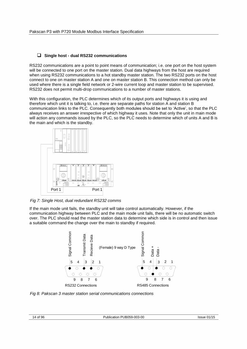
Single host - dual RS232 communications
RS232 communications are a point to point means of communication; i.e. one port on the host system will be connected to one port on the master station. Dual data highways from the host are required when using RS232 communications to a hot standby master station. The two RS232 ports on the host connect to one on master station A and one on master station B. This connection method can only be used where there is a single field network or 2-wire current loop and master station to be supervised. RS232 does not permit multi-drop communications to a number of master stations. With this configuration, the PLC determines which of its output ports and highways it is using and therefore which unit it is talking to, i.e. there are separate paths for station A and station B communication links to the PLC. Consequently both modules should be set to ‘Active’, so that the PLC always receives an answer irrespective of which highway it uses. Note that only the unit in main mode will action any commands issued by the PLC, so the PLC needs to determine which of units A and B is the main and which is the standby. If the main mode unit fails, the standby unit will take control automatically. However, if the communication highway between PLC and the main mode unit fails, there will be no automatic switch over. The PLC should read the master station data to determine which side is in control and then issue a suitable command the change over the main to standby if required.
Fig 8: Pakscan 3 master station serial communications connections
Fig 7: Single Host, dual redundant RS232 comms
Re
cie
ve
Data
Tra
nsm
it D
ata
12345
6789
Sig
nal C
om
mo
n
RS232 Connections
Da
ta -
RS485 Connections
Sig
nal C
om
mo
n
Da
ta +(Female) 9 way D Type
12345
6789
Port 1 Port 1
Port 1
Port 2
P3
PS730
Keyswitch
AutoA B
P3 P3
PS720
IIE Loop
Standby
Port A
Port B
P3
PS720
IIE Loop
Standby
Port A
Port B
P3
PS710
PakscanP3
StatusPri/Stby
PowerAlarm
PS
700
CPU/PSUPort 1
Port 2
PS710
PakscanP3
StatusPri/Stby
PowerAlarm
Option 1 Option 2 Switch
A BCE
Option 2 Option 1 CPU/PSU
roto
rk
rotork rotork rotork rotork rotork rotork rotork

Serial Communications
Issue 01/15 Publication PUB059-003-00 15 of 96
120
120+5V
Gnd
100
Data +
Data -
Off On
Off On
Port Terminations
Off On1
2Off On
General guidance
1. Both station A and B must be set to the same options with regard to all settings including the standby active/standby passive option.
2. When using an RS485 highway, care must be taken to ensure that it is correctly terminated at both ends (and only at the ends).
3. If the host system wishes to change over control of the loop such that master station A changes from main to standby or vice versa, it must do so by sending the change over command to either the main unit or the standby unit.
1.2.4 P3 master station – Port Function
The P3 master station chassis has DIP switches underneath the PS710 CPU module for setting the type of serial port that is presented at the port connectors.
The two DIP switches allow each port to be selected between RS232 and RS485. For RS485 slide the appropriate Port switch to the right, for RS232 they should be on the left.
Each of the two ports may be set independently.
1.2.5 P3 master station – RS485 termination
The master station chassis includes the DIP switches to select line termination and pull-apart resistors on the comms lines. All RS485 highways should be terminated correctly and when two wire data transmission is being used the possible errors in data that can occur during line turn around can be overcome with pull-apart resistors. Care must be taken to fit these resistor networks on the ends of the lines only; consequently the best location is at the PLC/DCS end of the multi-drop data highway. Prior to dispatch from Rotork these switches are normally set ‘Off’ to disable the resistors.
Fig 9: Port Function Switches shown in RS232 position
Port 1
RS232 RS485
Port 2
Fig 10: Port Termination Switches shown in Off position

Pakscan P3 with P720 Module Modbus Interface Specification
16 of 96 Publication PUB059-003-00 Issue 01/15
The two DIP switches are used to connect end of line termination resistors and biasing resistors to the RS485 network. All RS485 network highways should be terminated at both ends of the highway. Each port can be terminated independently.
1.2.6 P3 master station – RS485 Cross Connection (Hot Standby Systems)
The cross connection DIP switches allow the serial ports on the two sides of the hot standby master station to be connected together as a multi-drop pair. The port should only be cross connected when either Port 1 and/or Port 2 are set to RS485. If a port is cross connected then its associated “A Only” and “B Only” feedback switches must also be set to the Cross Connected position (moved to the right). The feedback switches are used to inform the master station and modify the default set up options for a cross coupled port to “standby passive”. 1.2.7 RS485 termination – Pakscan P3F master station
The Pakscan P3F master station has pull apart and termination resistors that can be selected for each port by setting the DIP switches in the correct positions. All highways should contain at least one pair of pull-apart resistors and at the ends of each highway a termination resistor should be present. Termination is not required unless the P3F is at the end of a highway.
Fig 11: Port Cross Connection and Feedback Switches shown in Not Cross Connected position
Fig 12: Pakscan P3F master station terminating resistors for RS485 2-wire highway
A Side Master
Port 1
Port 2
Cross Connect Switches(Shown not cross connected)
Port 1
Port 2
Data +
Data -
Feedback
Feedback
Port 1
Port 2
Feedback
Feedback
B Side Master
Data +
Data -
Data +
Data -
Data +
Data -
A Only
Not CrossConnected
CrossConnected
B Only
Port 1
Port 2
Port 1
Port 2
Port 1
Port 2
Port 2
Port 1

Serial Communications
Issue 01/15 Publication PUB059-003-00 17 of 96
Switch*
Ethernet Highway 1
Ethernet Highway 2
Port 1
Port 2
P3
PS730
Keyswitch
AutoA B
P3
P3
PS720
IIE Loop
Standby
Port A
Port B
P3
PS720
IIE Loop
Standby
Port A
Port B
P3
PS710
PakscanP3
Status
Pri/StbyPower
Alarm
PS
700
CPU/PSUPort 1
Port 2
PS710
PakscanP3
Status
Pri/StbyPower
Alarm
Option 1 Option 2 Switch
A BCE
Option 2 Option 1 CPU/PSU
roto
rk
rotork rotork rotork rotork rotork rotork rotork
Pakscan 3 Master Station
PLCPort 3 Port 4 Port 3 Port 4
Switch*
Switch
Ethernet Highway 1
Ethernet Highway 2
Pakscan P3F Master Stations
PLC Port 3 Port 4 Port 3 Port 4
Switch
Pakscan P 3
rotork P 3 F
Pakscan P 3
rotork P 3 F
1.3 Ethernet Communications to Pakscan master stations
The Pakscan P3 and P3F master stations include dual Ethernet ports for communication by Modbus TCP/IP or to the internet. 1.3.1 Ethernet Connection
Two Ethernet ports are available for connection to host DCS or PLC systems. A third Ethernet port is also available for connection to a laptop computer for configuration purposes. The master station is ready to use with Ethernet and Modbus TCP protocol for the DCS to access data and control the actuators on the field network. The IP address is already set and can be changed during setting up the master station
Fig 13: Ethernet, dual highway, from hot standby P3 master station to PLC
Fig 14: Ethernet Highway from PLC to Pakscan P3F master station

Pakscan P3 with P720 Module Modbus Interface Specification
18 of 96 Publication PUB059-003-00 Issue 01/15
* If Port 3 and Port 4 are being utilised at least one switch must be a managed switch and support either Spanning Tree Protocol (STP) or Rapid Spanning Tree Protocol (RSTP).
Setting-Up the Ethernet Comms
Ethernet connections require 10/100BaseT Ethernet Switches to connect the system together. Patch cords connect the ports on the master to the Switches. Independent highways are possible by using separate switches on each highway. The Pakscan master station defaults to the same IP address on both the ports. P3 Only: The same address can be used on the A and B master stations. It is possible to change the IP address on either master station, but the two ports always have the same address. When the A and B stations both use the same IP address it is important to set the Standby Action to Passive. The two Ethernet inputs are logically combined within the P3 master station. This means that Alarms read over either highway are effectively read over both and there is only one alarm data base. It is not recommended to use the two highways to access different host systems. The recommended highway setup should follow these guidelines
Use two main data highway busses, both of which connects to all the master stations
The master is left with a Static DHCP port setting
P3 Only: Each hot standby pair has the same IP address on its port 3 and port 4
P3 Only: The Standby action is set to passive (default is active)
Keep the number of host connections below 10 (The master station can serve up to 10 simultaneous host connections).
With this arrangement either PLC port can always communicate with the master station in control of the loop. Heartbeat data requests on the second highway will always be acknowledged with a response.
DHCP Static
Default IP address 10 200 1 1
Subnet mask 255 255 255 0
Standby Action (P3 only) Set to Passive

Serial Communications
Issue 01/15 Publication PUB059-003-00 19 of 96
2 DATA INTERPRETATION
This section describes the data organisation and meaning of the various data bits found in the protocol data for the Pakscan 3 Current Loop option.
2.1 Master station data
The Pakscan 3 Current Loop option perform various self-checking routines and control the 2-wire current loop. The status of the master station itself is available for interrogation by a host DCS over the serial interface. The relevant registers and the location of the data within them, together with the methods for reading and writing to these registers is detailed later in this document. The data is always related either to a field unit on the 2-wire current loop or to the master station module or the Current Loop module. This section provides the interpretation of the information reported by each data bit or register in the master station area of the data base and the available registers to which system instructions may be written. Note that the Pakscan P3F does not have hot standby capability and the data bits relating to this feature are not applicable. Information about the meaning of the information reported in the field unit area of the data base is contained in the individual field unit instruction manuals. A brief overview of these data bit interpretations follows later in this manual. 2.1.1 Data base segregation
Whichever data base Interface is chosen it will contain at least two sections. One of these is termed the Master Station Data Base, whilst the other is the Field Unit Data Base. The Field Unit Data Base contains the information from the attached devices on the current loop network, whilst the Master Station Data Base contains the system data.
Logical and physical master stations
The P3F master station has only one physical and one logical master station. The physical P3 master station (Current Loop access) may contain up to four logical master stations as described in the Generic and EPLCG Interface section. The logical master stations each have a different Modbus slave address and contain data about different groups of field units on the current loop. All of these logical master stations contain the same master station data. A command or write
Fig 15: Data base segregation
Host Comms Link
Master Station Data
Field Unit Data
Data Base
2 wire loop data
Pakscan P3 with P720 Module Modbus Interface Specification
20 of 96 Publication PUB059-003-00 Issue 01/15
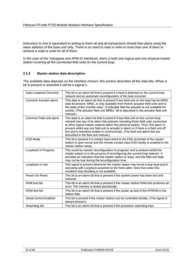
instruction to one is equivalent to writing to them all and all transactions should take place using the slave address of the base unit only. There is no need to read or write to more than one of them to achieve a read or write for all of them. In the case of the Yokogawa and APM-SI interfaces, there is both one logical and one physical master station covering all the connected field units on the current loop. 2.1.2 Master station data description
The available data depends on the interface chosen; this section describes all the data bits. When a bit is present or asserted it will be a logical 1.
Auto-Loopback Occurred This bit is an alarm bit that is present if a fault is detected on the current loop network and an automatic reconfiguration of the loop occurred.
Common Actuator alarm This data is an alarm bit that is present if any field unit on the loop has its MREL data bit present. MREL is only available from Rotork actuator field units and is the state of the ‘monitor relay’. It indicates that the actuator is not available for control. (The actuator field unit ‘MREL’ bit is described in the actuator field unit manual.)
Common Field Unit alarm This data is an alarm bit that is present if any field unit on the current loop network has any of its alarm bits present, including those field units connected to other logical master stations within this physical station. Thus, this alarm is present whilst any one field unit is actually in alarm or if there is a field unit off line and is therefore unable to communicate. (The field unit alarm bits are described in the field unit manual.)
ESD Mode This bit is present if a contact input wired to the ESD terminals of the master station is open circuit and the remote contact input ESD facility is enabled in the master station setup.
Loopback in Progress This could be named ‘reconfiguration in progress’ and is present whilst the master station is in the process of reconfiguring the current loop network. It provides an indication that the master station is ‘busy’ and the field unit data may not be true during the reconfiguration time.
Loopback in Use This signal is present whenever the master station has found a loop fault and is operating with Loopback asserted on the field cable. Note that under this condition loop doubling is not available.
Power On Reset This bit is an alarm bit that is present if the system power has been lost and restored.
RAM test fail This bit is an alarm bit that is present if the master station RAM test produces an error. The memory is tested periodically.
ROM test fail This bit is an alarm bit that is present if the power up test of the EPROM in the station fails.
Serial Control Enabled This bit is present if the master station can be controlled serially. (This signal is always present.)
Watchdog fail This bit is an alarm bit that is present if the processor watchdog trips.

Serial Communications
Issue 01/15 Publication PUB059-003-00 21 of 96
2.1.3 Alarm handling
Some of the data bits are described as ‘alarm bits’. These represent information that can be considered as an alarm. In each case the alarm bit is latched and it will not clear until the data has been read by the host, a serial data alarm accept has been issued to the master station and the source of the alarm has returned to normal. 2.1.4 Data relevant to hot standby systems
This data only has a true meaning for a P3 master station with a hot standby fitted. The left hand ‘A’ station is always the designated Main unit.
0 = A side,
1 = B side
This bit indicates ‘A station / B station communicating’. It is used to determine if the communication is to the left hand or right hand station (A or B) of a standby pair. The left hand ‘A’ unit is the designated ‘Main’ station. The data bit will be a 0 if the communication is to the ‘A’ station on the left-hand side. It is a 1 if the communication is to the B station on the right hand side.
Master Station ‘A’ OK (main unit)
This bit is present if the Main, A side, left hand, unit is functioning correctly.
Master Station ‘B’ OK (standby unit)
This bit is present if the Standby, B side, right hand unit is functioning correctly.
1 = Primary, (In Use),
0 = Standby, (Out of Use)
This bit is used to indicate if the station that is currently communicating on the serial link is in control of the current loop network or not. A ‘1’ indicates communication to a station that is in Main mode, whilst a ‘0’ indicates it is in Standby mode.

Pakscan P3 with P720 Module Modbus Interface Specification
22 of 96 Publication PUB059-003-00 Issue 01/15
2.1.5 Additional data available using Generic / EPLCG Interface
FCU Failure Count This is a series of registers containing data showing the absolute number of communication failures (including retries) for every connected field unit on the current loop. The maximum count for a field unit is 256 failures after which its counter rolls over to zero and starts again.
FCU Map This is a series of registers containing the field unit addresses in the order in which they are connected on the 2-wire current loop
FCU on Loop to Scan Up To
This register contains a number equal to the master station setting for the highest FCU address to look for.
FCU’s Connected This register contains data to show the number of FCU’s communicating on each of the current loop network ports. In normal circumstances all the FCU’s will be connected to Port A. However, if there is a cable fault, then some will be connected to Port A and some to Port B. The numbers indicate the position of the cable fault.
Field Unit Address Fault This register holds data about the position and address number that is found to be at fault during configuration.
Loop Baud Rate This register contains a number that may be decoded to give the loop baud rate setting.
Loop Configuration Process
This register changes its value as the master station proceeds through the stages used in configuring the loop.
Loop Fault Information This register holds data indicating loop faults that may be present and preventing complete loop configuration. Additionally it includes the last system reconfiguration code and the loop fault type.
PS720 Current Loop Card Software Version Number
This register contains a number collected from the loop card EPROM to indicate the software version that is in use.
Loop Test Result (%) This register holds a hex number for the result of the last loop test in percent.
Loop Test Speed The number in this register relates to the last Loop Test performed and the speed at which it was done.
Command Filter Timeout This register contains the timeout setting for the command filter.
Master Station Type Number
This register contains a number that identifies the type and capacity of the master station.
Serial Communications
Issue 01/15 Publication PUB059-003-00 23 of 96
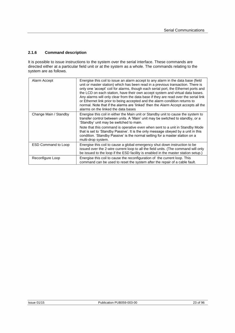
2.1.6 Command description
It is possible to issue instructions to the system over the serial interface. These commands are directed either at a particular field unit or at the system as a whole. The commands relating to the system are as follows.
Alarm Accept Energise this coil to issue an alarm accept to any alarm in the data base (field unit or master station) which has been read in a previous transaction. There is only one ‘accept’ coil for alarms, though each serial port, the Ethernet ports and the LCD on each station, have their own accept system and virtual data bases. Any alarms will only clear from the data base if they are read over the serial link or Ethernet link prior to being accepted and the alarm condition returns to normal. Note that if the alarms are ‘linked’ then the Alarm Accept accepts all the alarms on the linked the data bases
Change Main / Standby Energise this coil in either the Main unit or Standby unit to cause the system to transfer control between units. A ‘Main’ unit may be switched to standby, or a ‘Standby’ unit may be switched to main.
Note that this command is operative even when sent to a unit in Standby Mode that is set to ‘Standby Passive’. It is the only message obeyed by a unit in this condition. ‘Standby Passive’ is the normal setting for a master station on a multi-drop system.
ESD Command to Loop Energise this coil to cause a global emergency shut down instruction to be issued over the 2-wire current loop to all the field units. (The command will only be issued to the loop if the ESD facility is enabled in the master station setup.)
Reconfigure Loop Energise this coil to cause the reconfiguration of the current loop. This command can be used to reset the system after the repair of a cable fault.
Pakscan P3 with P720 Module Modbus Interface Specification
24 of 96 Publication PUB059-003-00 Issue 01/15
2.2 Field unit data
Field unit data is made available from the master station. The master station collects the data asynchronously from the connected field units in the actuators on the 2-wire current loop. The field units vary depending on the actuator in which they are fitted and the data available to report.
IQ3, ROMpak, CVA and CMA contain the common protocol field unit IQ1, IQ2 and IQT actuators contain the IQ mk1 field units IQ analogue field units can only be fitted to IQT actuators in addition to the IQ mk1 field unit,
IQ3 variant offers an option to include 2 analogue inputs to the same IQ field unit address by including extra analogue option cards.
A, AQ and Q range actuators have Integral type field units General Purpose field units are mounted away from the devices they control and can be set
to Actuator or General Purpose mode EH and SI actuators contain a derivative of the IQT field unit
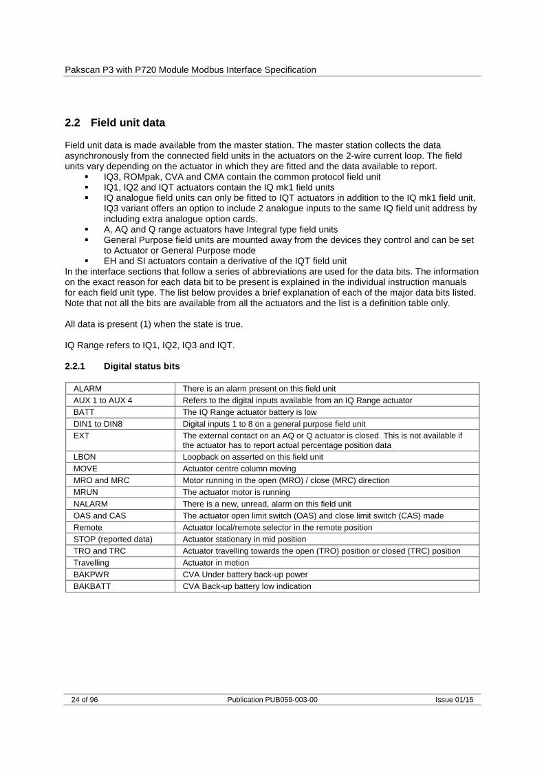
In the interface sections that follow a series of abbreviations are used for the data bits. The information on the exact reason for each data bit to be present is explained in the individual instruction manuals for each field unit type. The list below provides a brief explanation of each of the major data bits listed. Note that not all the bits are available from all the actuators and the list is a definition table only. All data is present (1) when the state is true. IQ Range refers to IQ1, IQ2, IQ3 and IQT. 2.2.1 Digital status bits
ALARM There is an alarm present on this field unit
AUX 1 to AUX 4 Refers to the digital inputs available from an IQ Range actuator
BATT The IQ Range actuator battery is low
DIN1 to DIN8 Digital inputs 1 to 8 on a general purpose field unit
EXT The external contact on an AQ or Q actuator is closed. This is not available if the actuator has to report actual percentage position data
LBON Loopback on asserted on this field unit
MOVE Actuator centre column moving
MRO and MRC Motor running in the open (MRO) / close (MRC) direction
MRUN The actuator motor is running
NALARM There is a new, unread, alarm on this field unit
OAS and CAS The actuator open limit switch (OAS) and close limit switch (CAS) made
Remote Actuator local/remote selector in the remote position
STOP (reported data) Actuator stationary in mid position
TRO and TRC Actuator travelling towards the open (TRO) position or closed (TRC) position
Travelling Actuator in motion
BAKPWR CVA Under battery back-up power
BAKBATT CVA Back-up battery low indication

Serial Communications
Issue 01/15 Publication PUB059-003-00 25 of 96
2.2.2 Alarm data bits
AUXOR On an IQ Range actuator this indicates that one of the auxiliary inputs is active
CNA Actuator remote control not available because the local/local stop/remote selector is not in the remote position
COMMS Communication failure between master station and field unit
EOT Actuator continues to run the motor beyond the end of travel limit switch
LOCAL IQ Range Actuator local/local stop/remote selector in the local position
LSTOP Local/local stop/remote selector in the Local Stop position
MEMF Memory chip fault
MMOVE Manual movement of the valve detected
MOP and MCL Actuator has reached the open (MOP) or close (MCL) position due to manual movement of the handwheel. MOP is manually opened, MCL is manually closed
MOPG and MCLG Actuator has left the close position (MOPG) or the open position (MCLG) due to manual movement of the handwheel. MOPG is manual opening of the valve and MCLG is manual closing of the valve
MREL Actuator monitor relay tripped. The monitor relay is a combination signal for the thermostat, local stop or local signals being present in electric actuators. In hydraulic or pneumatic actuators the signal is a combination of loss of pressure or local or off selected on the local/remote selector
POWR Field unit power on reset alarm
SFAIL Actuator fails to start or stop when expected to do so
THERM Actuator thermostat tripped
FAULT EH or SI actuator general fault indication
VJAM Valve jammed at end of travel causing a torque trip
VOBS Obstructed valve causing actuator to torque trip in mid travel
VTT On an IQ Range, EH and SI this indicates valve travel time exceeded
2.2.3 Field unit commands
The actuators on the loop can be commanded to open, close, or stop by writing to the appropriate location in the data base. In all cases, there is no requirement to cancel a command to remove it. A new command will always remove any existing commands. IQ Range, CVA, EH, SI and CMA actuators are capable of adopting an analogue position (0-100%). Note that A, AQ, Q and ROMpak actuators may require additional parts before they can provide this capability. Writing an analogue position to the appropriate register cancels any existing command. Writing an open/stop/close command will cancel any analogue setting previously made. General purpose field units can have their relay outputs operated (energised or de-energised) and additionally they have an analogue output signal. Similar to actuator commands, with the GPFCU relays there is no requirement to cancel a command to remove it unless the relay outputs have been set to ‘Maintained’ action within the field unit.
OPEN Causes the actuator to move to the open position
STOP Causes the actuator to stop
CLOSE Causes the actuator to move to the close position
ESD Causes the actuator to adopt the internally set Emergency Shut Down position (which may be open. close or stay put)
Pakscan P3 with P720 Module Modbus Interface Specification
26 of 96 Publication PUB059-003-00 Issue 01/15
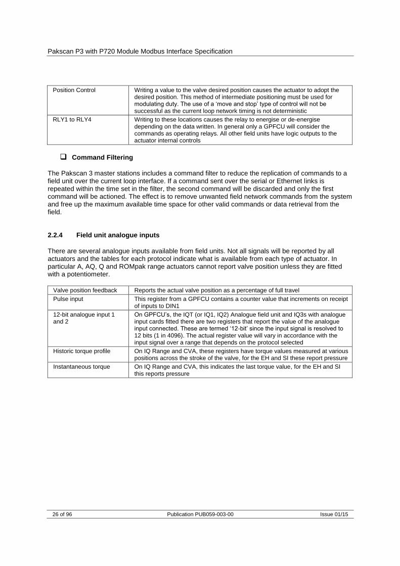
Position Control Writing a value to the valve desired position causes the actuator to adopt the desired position. This method of intermediate positioning must be used for modulating duty. The use of a ‘move and stop’ type of control will not be successful as the current loop network timing is not deterministic
RLY1 to RLY4 Writing to these locations causes the relay to energise or de-energise depending on the data written. In general only a GPFCU will consider the commands as operating relays. All other field units have logic outputs to the actuator internal controls
Command Filtering
The Pakscan 3 master stations includes a command filter to reduce the replication of commands to a field unit over the current loop interface. If a command sent over the serial or Ethernet links is repeated within the time set in the filter, the second command will be discarded and only the first command will be actioned. The effect is to remove unwanted field network commands from the system and free up the maximum available time space for other valid commands or data retrieval from the field. 2.2.4 Field unit analogue inputs
There are several analogue inputs available from field units. Not all signals will be reported by all actuators and the tables for each protocol indicate what is available from each type of actuator. In particular A, AQ, Q and ROMpak range actuators cannot report valve position unless they are fitted with a potentiometer.
Valve position feedback Reports the actual valve position as a percentage of full travel
Pulse input This register from a GPFCU contains a counter value that increments on receipt of inputs to DIN1
12-bit analogue input 1 and 2
On GPFCU’s, the IQT (or IQ1, IQ2) Analogue field unit and IQ3s with analogue input cards fitted there are two registers that report the value of the analogue input connected. These are termed ‘12-bit’ since the input signal is resolved to 12 bits (1 in 4096). The actual register value will vary in accordance with the input signal over a range that depends on the protocol selected
Historic torque profile On IQ Range and CVA, these registers have torque values measured at various positions across the stroke of the valve, for the EH and SI these report pressure
Instantaneous torque On IQ Range and CVA, this indicates the last torque value, for the EH and SI this reports pressure

Modbus Specification
Issue 01/15 Publication PUB059-003-00 27 of 96
3 MODBUS SPECIFICATION
3.1 Electrical specification
Serial data Line Electrical Specification RS485 or RS232 Ethernet 10baseT
3.2 Outer protocol
Modbus Transmission Mode RTU (8-bit binary data) Ethernet Modbus TCP/IP Server
3.3 Serial Data
Baud Rate P3 and P3F master stations 2400, 4800, 9600, 19200, 38400, 57600, or 115200 Number of bits per character: start bits 1 data bits (LSB first) 8 parity (configurable) Odd, Even, None, Always 0 stop Bits 1 Error checking CRC Modbus message turn round time Minimum period between request and response 2400 16.00 mSec (3.5 character period t3.5 according to the 4800 8.00 mSec Modbus Serial Line Implementation Guide V1.02, 9600 4.00 mSec fixed at 1.750 mSec above 19200) 19200 2.00 mSec 38400 1.75 mSec 57600 1.75 mSec 115200 1.75 mSec Maximum period between request and response 100 00 mSec The Modbus protocol supports two forms of data access Discrete (or Bit) and Register addressing. The Function Code determines which form of addressing is to be used.
3.4 Overview of the design
Modbus commands may be transmitted to the Pakscan 3 master stations via Ethernet, RS232 or RS485 physical interfaces. Up to 32 master station modules may be linked on a single RS485 highway to one host port. Each Pakscan 3 master station Current Loop Interface permits up to 240 field units to be connected to it. The Pakscan P3F master station supports up to 32 field units The master station responds as a MODBUS SLAVE or SERVER to messages from the host. The serial ports can each use different data bases, whilst the two Ethernet ports must both use the same data base and protocol. Within the master station the Modbus address that the master station will

Pakscan P3 with P720 Module Modbus Interface Specification
28 of 96 Publication PUB059-003-00 Issue 01/15
respond to is set using the front keypad or web pages and the protocol used on the particular port is also set in the same way. The master station maintains a sectioned data base covering all its connected field units, and the host reads this data without the need to access field units directly. The master station main module performs the functions of Data Concentrator and interface whilst the Current Loop module is the 2-wire loop master. Within the field units, data is organised into processing blocks. Each block performs a specific function such as analogue scale and bias, characterised by a number of parameters. Modbus data locations within the master station Current Loop module data base relating to itself or a field unit are calculated by using the Block number, Parameter number, and field unit Address (see 4.3.3 Register and Discrete Address Formulae).
Fig 16: Data base Connections
Generic
EPLCG
Yokogawa
Honeywell SI
Serial Port 1
Serial Port 2
Ethernet Port 3
Ethernet Port 4
Data Base 2
Data Base 3
System and
NetworkData
Data Base 1
Generic
EPLCG
Yokogawa
Honeywell SI
Generic
EPLCG
Yokogawa
Honeywell SI

Generic and Honeywell EPLCG Protocols
Issue 01/15 Publication PUB059-003-00 29 of 96
4 GENERIC AND HONEYWELL EPLCG PROTOCOL INTERFACE SPECIFICATION
This section describes the two protocols that allow access to the maximum amount of data within the master station. The tables give locations for the data which may be read from either registers or discrete locations, or in some cases, both. The Generic protocol has access to all the blocks and parameters within the data base and is the most flexible choice. The Honeywell EPLCG protocol also allows access to all the blocks and parameters and has been specially tailored to meet the requirements of the Honeywell EPLCG gateway. Honeywell has approved this version as suitable for connection to their gateway. On the Pakscan 3 Current Loop Option Module select 'GENERIC MODBUS' for the Generic configuration of the data base or ‘HONEYWELL EPLCG’ for the EPLCG version of the data base: the difference between these two choices is in the analogue data scaling only. Generic uses 16-bit 2’s complement and EPLCG uses a 12-bit value in the register. Care must be taken to ensure that the correct protocol is routed to the port being used for the application concerned. Rotork’s own In-Vision system, for example, uses the Generic Modbus data base. The Modbus address is used to gain access to the correct section of the data base for the field unit whose data is to be collected. For a P3F master station there is only one address to cover all its field units, but with Pakscan 3 and the Current Loop module the Pakscan 2 base address does not cover the whole range of field unit addresses. The lowest, or Base, Modbus address allows access to the first 60 field units, the next address the next 60 field units and so on
4.1 Modbus unit address (Generic and Honeywell EPLCG protocols)
The first byte of all Modbus message frames is the Modbus Address byte. Modbus supports 248 addresses, of which value 0 is always allocated for Broadcast messages. This leaves 247 addresses for use by connected devices on the Modbus data link. Each master station is configured with a Modbus Base Address, which may be anywhere in the range 1 to 247.
Modbus Address
Function Code
Register or Discrete Address
Number of Registers or
Bits
Data Field
CRC Check
8 bits 8 bits 16 bits 16 bits N bits 16 bits
The P3F master station responds to the selected Modbus address. Each P3 master station Pakscan 2 Current Loop module will then respond to between 1 and 4 Modbus addresses depending on how many field units it has been configured to support. Physically a P3 master station is only one unit on the Modbus highway, but logically as far as the protocol is concerned it can appear to be up to 4 units. Each logical unit supports up to 60 field units. As far as Modbus is concerned, each unit behaves as an independent slave. Fig. 18 illustrates this and Fig. 19 correlates the real field unit address with which logical master station unit it appears to be attached. Users may find that when assigning Modbus addresses for use on the network, configuring
Fig 17: Modbus transaction format

Pakscan P3 with P720 Module Modbus Interface Specification
30 of 96 Publication PUB059-003-00 Issue 01/15
the setting of the Base address of the master station using increments of 4 will ensure future expansion space.
Field Unit Address
Number of Modbus Addresses Master Station Responds To
Modbus Address
1 to 60 61 to 120 121 to 180 181 to 240
1 2 3 4
Base Base + 1 Base + 2 Base + 3
Examples: Physical Field Unit address 10 is accessed as FCU No. 10 within Modbus Base address. Physical Field Unit address 61 is accessed as FCU No. 1 within Modbus Base address +1. Physical Field Unit address 165 is accessed as FCU No. 45 within Modbus Base address +2.
Fig 19: Modbus address organisation
Physical arrangementModbus highway
Loop with up to 240 field units
MasterStation
Logical arrangement
Master Station comms port
DATA BASE
Master StationBase Address
60 field units
DATA BASE
Master StationBase + 1
60 field units
DATA BASE
Master StationBase + 2
60 field units
DATA BASE
Master StationBase + 3
60 field units
Data FCU 1 - 60 Data FCU 61 - 120 Data FCU 121 - 180 Data FCU 181 - 240
Modbus highway
Loop with up to 240 field units
Port 1
Port 2
P3
PS730
Keyswitch
AutoA B
P3 P3
PS720
IIE Loop
Standby
Port A
Port B
P3
PS720
IIE Loop
Standby
Port A
Port B
P3
PS710
PakscanP3
StatusPri/Stby
PowerAlarm
PS
700
CPU/PSUPort 1
Port 2
PS710
PakscanP3
StatusPri/Stby
PowerAlarm
Option 1 Option 2 Switch
A BCE
Option 2 Option 1 CPU/PSUro
tork
rotork rotork rotork rotork rotork rotork rotork
Fig 18: Pakscan P3 master station model – Generic and Honeywell EPLCG protocol

Generic and Honeywell EPLCG Protocols
Issue 01/15 Publication PUB059-003-00 31 of 96
4.2 Modbus function code support (Generic and Honeywell EPLCG protocols)
Details of Request and Reply formats are contained in the Modbus Reference Guide. The following section deals with how Pakscan 3 master stations interpret the commands. Fig 20 lists the supported Modbus commands.
Function Code
Modbus Name Master Station Meaning Addressing
01
02
03
04
05
06
08
15
16
17
Read coil status
Read input status
Read holding registers
Read input registers
Force single coil
Preset single register
Loopback diagnostic test
Force multiple coils
Preset multiple registers
Report slave ID
Read master station status
Read FCU status
Read master station status
Read FCU status
Discrete output
Register output
Multiple discrete outputs
Multiple register outputs
Discrete
Discrete
Register
Register
Discrete
Register
Discrete
Register
Error code Meaning
01
02
03
06
Illegal function code or incorrect message length
Illegal data address (Register address invalid)
Illegal data value (value in data field out of range)
Slave Device Busy
To read data the function code to use will depend on whether the data is to be read as single bits or as 16 bit registers and also whether it is to be field unit or master station data. For example, code 01 reads master station data as discrete bits, whereas code 03 reads the same data as registers. Discrete and Register access read the SAME data. For Discrete access, the Discrete address field is interpreted as a Bit offset into the data base. For Register access, the Register address field is interpreted as a Register location address in the data base.
Function Code 01 - Read Master Station Status (Bits)
Function code 01 is used to read discrete (bit) data from the data base to obtain information about the master station itself. Note: This function code is not generally supported for use in reading data from the data base for field unit information. The exception is where the gateway is set up to read the data from the actuator
Fig 20: Modbus function codes and error codes
Pakscan P3 with P720 Module Modbus Interface Specification
32 of 96 Publication PUB059-003-00 Issue 01/15
command open or close coils, for example prior to writing data, this is permitted by the master station. However, the coils do not physically exist and the data read back by the host is the current status of the Open and Close limit switch in the actuator (OAS for an Open command and CAS for a Close command). These signals may not reflect the state of the command coil. For example the actuator may have been opened by a system command to the open coil and then closed manually. The coil for open would be expected to be ‘on’, but the actuator will report the close coil as being ‘on’ since CAS will be present, and the open coil as being ‘off’. In addition for actuator control all the write signals become pulsed outputs at the field unit and the actuator responds to these pulse commands itself.
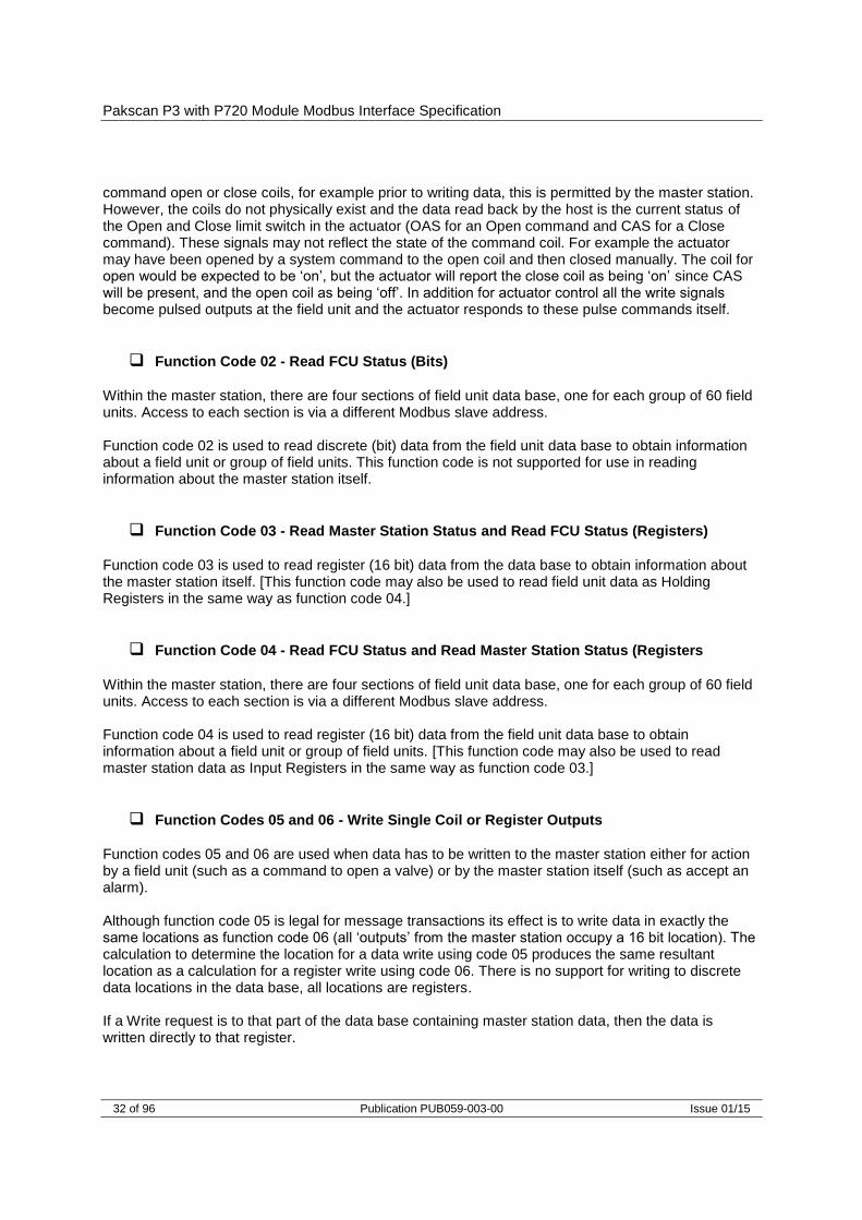
Function Code 02 - Read FCU Status (Bits)
Within the master station, there are four sections of field unit data base, one for each group of 60 field units. Access to each section is via a different Modbus slave address. Function code 02 is used to read discrete (bit) data from the field unit data base to obtain information about a field unit or group of field units. This function code is not supported for use in reading information about the master station itself.
Function Code 03 - Read Master Station Status and Read FCU Status (Registers)
Function code 03 is used to read register (16 bit) data from the data base to obtain information about the master station itself. [This function code may also be used to read field unit data as Holding Registers in the same way as function code 04.]
Function Code 04 - Read FCU Status and Read Master Station Status (Registers
Within the master station, there are four sections of field unit data base, one for each group of 60 field units. Access to each section is via a different Modbus slave address. Function code 04 is used to read register (16 bit) data from the field unit data base to obtain information about a field unit or group of field units. [This function code may also be used to read master station data as Input Registers in the same way as function code 03.]
Function Codes 05 and 06 - Write Single Coil or Register Outputs
Function codes 05 and 06 are used when data has to be written to the master station either for action by a field unit (such as a command to open a valve) or by the master station itself (such as accept an alarm). Although function code 05 is legal for message transactions its effect is to write data in exactly the same locations as function code 06 (all ‘outputs’ from the master station occupy a 16 bit location). The calculation to determine the location for a data write using code 05 produces the same resultant location as a calculation for a register write using code 06. There is no support for writing to discrete data locations in the data base, all locations are registers. If a Write request is to that part of the data base containing master station data, then the data is written directly to that register.

Generic and Honeywell EPLCG Protocols
Issue 01/15 Publication PUB059-003-00 33 of 96
If the Write request is to that part of the data base relating to a field unit, then the information contained in the message is translated into a command that a field unit understands and sent to the field unit over the current loop network. The rate at which instructions are sent to the master station should not exceed the rate at which they can be sent on to the field units. The sequence of events is: (1) - Write command received by the Master Station (2) - Response sent back to Host (3) - Write message sent to Field Unit A good response to the Host indicates that the request was received correctly, the message length is acceptable, and that the addressed field unit is on-line. It does not indicate that the write to the field unit was successful. Confirmation of a successful write comes some time later when new data is reported as a change in the main data base. If commands are written at too high a rate then the current loop network is prevented from collecting data from the field units and the system will appear to slow down. The Command Filter provides some protection against too high a frequency of writing commands. It causes the system to ignore duplicated commands to the same field unit if the duplicate is within the time setting for the filter.
Function Code 08 - Loopback Diagnostic Test
The purpose of the Loopback Test is to test the communication system between the host and the master station. Only Diagnostic sub-code 00 (Return Query Data) is supported.
Function Code 15 and 16 - Write Multiple Outputs
Function codes 15 and 16 may be used when data has to be written to more than one register in the master station either for action by a field unit (such as a command to open a valve) or by the master station itself (such as accept an alarm). Although function code 15 is legal for message transactions its effect is to write data in exactly the same locations as function code 16 (all ‘outputs’ from the master station occupy a 16 bit location). The calculation to determine the location for a data write using code 15 produces the same resultant location as a calculation for a register write using code 16. As with single instructions there is no support for writing data to discrete data locations, all locations are registers. The master station is able to accept a single transaction multiple write message containing information to be written to a maximum of 123 registers. These instructions are then passed to a queue for onward transmission over the current loop network. The rate at which the data is written into the master station must not exceed the rate at which it can be sent on to the field units. The command filter will remove duplicated commands in the same way as for function code 01 writes. In the case of actuator control there is never a need to write to turn a register or coil ‘off’ as the output is always treated as a pulse. If commands to turn off registers are sent these will be obeyed by the system with no actual result, the output already having turned off. The effect of sending these unnecessary commands will be to congest the communication on the current loop network.
Pakscan P3 with P720 Module Modbus Interface Specification
34 of 96 Publication PUB059-003-00 Issue 01/15
Function Code 17 - Report Slave ID
The response format is: Byte count field - 6 Slave ID field - 40 Runlight field - 255 Device dependent data (4 bytes) - HW version (16 bits) - SW version (16 bits)
Error Codes 01, 02, 03 and 06
Error code 01 will be presented back to the host if the function code in the data message is not one of those supported by the master station, or if the message length is incorrect. Error code 02 will be presented back to the host if the Data Address is illegal; or if the write command is a multiple write (code 15 or 16) where the number of coils or registers exceeds the amount acceptable. Error code 03 will be presented back to the host if the value contained in the data query field is illegal. Error code 06 will also be sent back to the host if the master station has insufficient buffer space to handle the write request to coils or registers in a single transaction. Buffer space will become free as the writes are issued to the loop and field units.
4.3 Data base access (Generic and Honeywell EPLCG protocols)
The total data base for the Pakscan system is distributed across all the connected master stations. Each master station contains data base records relating to itself and the field units on the current loop connected to it. 4.3.1 Data Organisation
The data base comprises a series of records organised into Blocks and Parameters. Each parameter contains 16 bits of data. There are 32 Blocks each of 8 Parameters associated with data about the master station itself and 32 Blocks each of 8 Parameters for each field unit on the current loop. The data to be found in each record is listed in section 4.5 for master stations and in section 4.6 for the field units. 4.3.2 Data Read Requests
If the request is for several registers, the address defines the start point for a group of Blocks and Parameters. The contiguous records in these registers are either associated with the master station itself, or with a GROUP of field units. This is particularly useful to collect, for example, the Alarm information from all field units connected to one master station in a single Modbus transaction. The alternative is to collect it with multiple transactions, one for each field unit address in use.

Generic and Honeywell EPLCG Protocols
Issue 01/15 Publication PUB059-003-00 35 of 96
4.3.3 Register and Discrete Address Formulae
The following formulae allow discrete and register addressing to be calculated. Section 3.5 and 3.6 should be referred to, to determine the meaning of particular bits and parameters. To use these formulae, first decide which 'bits' and 'registers' of information need to be collected, and which need to be written to. This will provide Field Unit, Block, Parameter, and Bit numbers that can be used in the equations. Note that the Modbus address for the particular master station also has to be known. (The FCU addresses will all be in the range 1-60 even if there are more than 60 field units connected. The master station address increments for each successive group of 60 field units.) Next, decide if register or discrete reads and writes are to be used and then determine the function code applicable. Finally, calculate the relevant start point in the data base using the information below. Modbus Slave Address = Master Station base address (for physical FU 1-60) = Master Station base address + offset (for physical FU above 60)
Function code 01: Read Master Station Status by Bits
Start Discrete = (128 x B) + (16 x P) + D see Note 1
Function code 02: Read FCU Data by Bits – Only applies to Blocks 0 to 7
Start Discrete = (7680 x P) + (960 x B) + (16 x [N-1]) + D see Note 1
Function code 03: Read Master Station Status by Register
Start Register = (8 x B) + P
Function code 04: Read FCU Data by Register
Start Register = 256 + (480 x B) + (60 x P) + (N-1)
Function code 05 or 15: Write Master Station Data by Single or Multiple Bits
Start Coil = (8 x B) + P see Note 2
Function code 05 or 15: Write FCU Data by Single or Multiple Bits
Start Coil = 256 + (480 x B) + (60 x P) + (N-1) see Note 2

Pakscan P3 with P720 Module Modbus Interface Specification
36 of 96 Publication PUB059-003-00 Issue 01/15
Function code 06 or 16: Write Master Station Data by Single or Multiple Register
Start Register = (8 x B) + P see Note 2
Function code 06 or 16: Write FCU Data by Single or Multiple Register
Start Register = 256 + (480 x B) + (60 x P) + (N-1) see Note 2 In the formulae above, the following symbols are used: N = FCU address (range 1 to 60) B = Block number P = Parameter number D = Data bit number within parameter (register).
Note 1 - Limited address range
This formula (reading discrete FCU data) has been carefully designed to allow for those Modbus hosts that have a limited address range. Parameter 0 has the most useful data and is located near the top end of the address field.
Note 2 - Writing Data
The master station recognises write requests to both coils and registers. In the calculation of the location of the coil or register to be written to, the start location is the same for both types of ‘write’. The master station considers coils and registers to be the same; they are always a whole parameter. There is no support for writing to an individual bit within a parameter. Where multiple writes are used the maximum number that may be written in a single transaction 123 registers, if the host attempts to write more than this or the internal buffer is full error code 02 is returned by the master station and no action taken. The rate at which data is written should not exceed the rate at which it can be transferred to the current loop network.
Note 3 - Address offsets
This table and the examples are for a typical Modbus implementation only. Check your system documentation carefully.
The discrete and register addresses calculated in the formulae are those which should appear in the messages as they are transmitted on the Modbus link to the master station. Some Modbus hosts offset addresses as far as the user is concerned. In such cases, the address programmed by the user into the host would be different from those calculated. Check Host system documentation carefully.
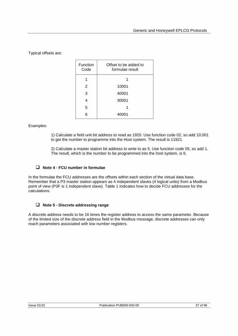
Generic and Honeywell EPLCG Protocols
Issue 01/15 Publication PUB059-003-00 37 of 96
Typical offsets are:
Function Code
Offset to be added to formulae result
1
2
3
4
5
6
1
10001
40001
30001
1
40001
Examples:
1) Calculate a field unit bit address to read as 1920. Use function code 02, so add 10,001 to get the number to programme into the Host system. The result is 11921. 2) Calculate a master station bit address to write to as 5. Use function code 05, so add 1. The result, which is the number to be programmed into the host system, is 6.
Note 4 - FCU number in formulae
In the formulae the FCU addresses are the offsets within each section of the virtual data base. Remember that a P3 master station appears as 4 independent slaves (4 logical units) from a Modbus point of view (P3F is 1 independent slave). Table 1 indicates how to decide FCU addresses for the calculations.
Note 5 - Discrete addressing range
A discrete address needs to be 16 times the register address to access the same parameter. Because of the limited size of the discrete address field in the Modbus message, discrete addresses can only reach parameters associated with low number registers.

Pakscan P3 with P720 Module Modbus Interface Specification
38 of 96 Publication PUB059-003-00 Issue 01/15
4.4 Notes on the use of the Generic and EPLCG Modbus protocol
Normally a Modbus host will be set up to cyclically read data representing key variables of the master station and field units. It can do this using Read Register function codes (03 and 04), and Read Discrete Status function codes (01 and 02). Parameters may contain either digital (bit) information or analogue (register) information. For digital records the Modbus discrete addressing commands are appropriate, whilst for analogue information the Modbus register address commands should normally be used. Register and Discrete addresses in this specification are the addresses that should be used within messages on the Modbus data link. Modbus host software may need to be configured with addresses that are 1 more than those which must appear on the link. This is due to the Host regarding addresses as starting from 1, not 0. Reading a group of registers in one transaction is more efficient than reading one register at a time. Support for Modbus diagnostic code (function code 08) is provided, but it is not obligatory to use it. . The master station includes Alarm Accept logic with respect to field unit alarms. Alarms from field units are automatically accepted by the master station (so the field unit can clear its alarm latches) and latched within the master station. These alarms must be read by the Host and then accepted (with an Alarm Accept write, to master station Block 0 Parameter 5), before they can clear. 4.4.1 Suggested Scan Cycle
The Host should be configured to scan data from the master station in the following order: Read Alarm Status Read Digital Status Perform Alarm Accept (Only strictly necessary if any new alarms have occurred) Read Analogue Status (If any analogue data is to be read) Commands to field units may be fitted in as required. In some applications it may be desirable to scan some items e.g. analogues, less frequently than others. This is perfectly acceptable. 4.4.2 Writing to Coils
When writing to a coil the data field to turn off the coil has to be 0x0000. As the most common device connected is an actuator whose action is controlled by a pulse output there is often no need to turn off a coil that has previously been turned on. The output command from the DCS should, where possible, use a pulse type output. When writing to a coil the data field to turn on the coil may be 0xFF00 or any other non zero value.
Generic and Honeywell EPLCG Protocols
Issue 01/15 Publication PUB059-003-00 39 of 96
4.4.3 Readback of Holding Registers
The master station supports the reading of the data in the Holding Registers. This data may not accurately reflect the state of the actuator as it could have been moved manually since the data was written. The data is a 2’s complement 16 bit value (0x0000 – 0x7FFF in the case of the Generic protocol or 0x0000 – 0x0FFF in the case of the Honeywell EPLCG). It is calculated from the actual value used in the data transaction over the current loop network to the field unit. When ‘read back’ this value may differ by 1 digit due to rounding errors in the calculation. The value sent to the field unit when the register was written will be true. To establish the actual valve position the Input Register relating to the field unit Measured Value should be read. 4.4.4 Alarm Handling
The serial communication ports on the master station are each served by their own independent data base and alarm handling. The handling of alarms on one serial port does not reflect on the alarms of any of the other serial ports unless the master station is set to Link the alarms. On a Pakscan 3 system the two Ethernet ports share another independent data base with its own alarm handling which is common to both Ethernet ports. In the data base there is a group of 16 bits of data defined as the 'Alarm Block' for each field unit, (for example, 'COMMS' is an alarm bit). Similarly, there are System Alarms as listed in section 3.6, (for example 'RAM test fail'). These data bits will all be latched by the master station if they should actually occur. The master station will therefore capture a transient alarm and keep it in its data base ready for the host to read it. Any latched alarm from these data areas will only be reset on three subsequent conditions. Firstly the alarm bit must be read by the host, secondly the alarm bit must be accepted by the host (this is done by issuing an 'Alarm Accept'), and finally the source of the alarm itself must return to normal. An example of the sequence would be: Consider an Actuator Thermostat.
1. Thermostat gets hot and trips. 2. Host reads data bit for the thermostat for this actuator 3. Host issues Alarm Accept; this is registered by the system as applicable to the
Thermostat Trip alarm. 4. The data bit remains set until the actuator cools down. 5. Once cooled below the trip point the data bit returns to normal.
If the host does not read the Thermostat bit for this field unit then the bit will remain set for all time (in this data base), even though the actuator cools down. Also if the host does not read this bit any Alarm Accept will not allow the alarm to reset itself. Any alarm bit must be read before it is able to be accepted. If the alarms are read infrequently then the above procedure guarantees that the host will register any and every alarm from the alarm block. In addition to the alarm data for each field unit there is a 'Status Block'. These status locations also contain information about the presence (or absence) of alarms in the Alarm Block.

Pakscan P3 with P720 Module Modbus Interface Specification
40 of 96 Publication PUB059-003-00 Issue 01/15
'Alarm' bit
For each field unit the 'Alarm' bit will be present if any of the source signals used to set bits in the Alarm block are present. Notice that the Alarm bit is an OR function of any alarm before the latch for that alarm. The 'Alarm' bit is latched and will not clear until it has been read, accepted and the source of the alarm has returned to normal. In the example of the thermostat, the 'Alarm' bit will be set when the thermostat is initially tripped.
'New Alarm' Bit
For each field unit 'New Alarm' will be present every time a new alarm is detected as occurring in the field unit. However, every time an Alarm Accept is issued this data bit will be reset even if the alarm itself is still present. The purpose of this bit is to indicate to the Host that there is a new alarm to be read from the alarm block.
System Common Alarms
In the master station Block 0 Parameter 0, bit 2 will be set if any field unit has its own 'Alarm' bit set. Thus the 'Common Field Unit Alarm' is set whilst any one field unit has an input actually in alarm, or if there is a field unit off line that is therefore unable to communicate. Block 0 Parameter 0, bit 3 contains a similar common data bit derived from the actuator 'Monitor Relay' source signals. 4.4.5 Use of Alarm Bits
The host may be configured to read as many, or all, of the alarm block data bits as required. (Those that are not being used will possibly fill up as alarms over the course of operating the Pakscan system; this will not have any detrimental effect on the system.) For the alarms that are used they will individually appear in the data locations being read, and by means of the Alarm Accept process will transfer to the host. They will also reset themselves as they return to normal providing they are read and accepted. The 'Alarm' bit will inform the host that any alarm is present, even those not normally being identified by the host as relevant. This bit may be used by the host as a flag that an alarm is currently present on a field unit. The host must take care of latching these bits in its own alarm handling system. This bit is analogous to a contact input that is self-resetting. As it is taken from before the internal latch, it is a true statement of the current alarm situation on the field unit. The 'New Alarm' bit may be used to indicate to the host that an alarm reading process is required, or that an ‘Alarm Accept’ write is required. The New Alarm will by its very nature disappear once the Accept is issued irrespective of the actual plant status as it has to be available for each new alarm.

Generic and Honeywell EPLCG Protocols
Issue 01/15 Publication PUB059-003-00 41 of 96
4.5 Master station data base (Generic and Honeywell EPLCG protocols)
The discrete and register numbers listed in the tables all start from '0', for example register 40000 would be referenced as 0000 in the serial transaction message and not as 0001. 4.5.1 Master Station Read Only Data
This set of registers exists in each of the four 'logical' master stations that exist within a single physical master station. The Modbus address used in transactions must be the master station Base address. Reading data from any one of the addresses is the same as any other as all four contain the same data. All the location numbers listed in this appendix are decimal numbers and zero based.
BLOCK 0 – Read Only Data (accessed with Modbus function code 01, 03 or 04) Register Location
Parameter 0 – System Status and Alarm 0
Discrete Location
Bit 0 Loopback in Progress 0
Bit 1 Loopback in Use 1
Bit 2 Common Field Unit Alarm 2
Bit 3 Common Actuator Alarm 3
* Bit 4 0 = A side, 1 = B Side 4
Bit 5 ESD Mode 5
Bit 6 Reserved 6
* Bit 7 1 = Primary, (In Use), 0 = Standby, (Out of Use) 7
Bit 8 Failure On Start-up 8
Bit 9 Reserved 9
Bit 10 Power On Reset 10
Bit 11 Watchdog Fail 11
Bit 12 Auto-Loopback Occurred 12
Bit 13 Field Unit in Comms Fail 13
* Bit 14 P3 Master Station ‘A’ OK (main unit, left side) 14
* Bit 15 P3 Master Station ‘B’ OK (standby unit, right side) 15
Register Location
Parameter 1 - FCU on loop to Scan Up To 1
Data = XXXX, Highest FCU Address
Parameter 2 - Loop Baud Rate Code 2
1 = 110 Baud
2 = 300 Baud
3 = 600 Baud
4 = 1200 Baud
5 = 2400 Baud
6 = 4800 Baud
Parameter 3 - Loop Scan Count 3
Data = Counter Value
Note: Data bits marked * are not relevant to single P3 master stations are not relevant to P3F master stations

Pakscan P3 with P720 Module Modbus Interface Specification
42 of 96 Publication PUB059-003-00 Issue 01/15
BLOCK 0 – Read Only Data (accessed with Modbus function code 01, 03 or 04) Register Location
Parameter 4 - Loop Fault Information 4
Bits 15-12 Loop Address Faults
Bit 15 0 = Port A, 1 = Port B
Bit 14 Duplicate Address found
Bit 13 Address Too High found
Bit 12 Zero Address found
Bit 11-8 Loop fault type
5 = Loop open circuit
6 = Loop short circuit
Bits 7-0 Reason why loop last configured
1 = Reset occurred
2 = FCU found at address zero
3 = FCU found at too high address
4 = Two FCU's at same address found
5 = Loop fault on outward wire (loop complete)
6 = Loop fault found on A side (LB's in use)
7 = Loop fault found on B side (LB's in use)
8 = Test of 'return' wire failed
9 = Loop configure command received
Parameter 5 - Field Unit Address Fault data 5
Bits 15-8 Loop position of address fault
Bits 7-0 Offending address
Parameter 6 - Loop Configuration Progress 6
1 = Wait for loopbacks 1
2 = Find FCU's on Port A
3 = Test loop
4 = Find FCU's on Port B
5 = Wait for loopbacks 2
6 = Loopbacks off on Port A
7 = Loopbacks off on Port B
8 = Program Baud Rate on Port A
9 = Program Baud Rate on Port B
Parameter 7 – Number of FCU’s found in Loop Configuration 7
Bits 8-15 Number of FCU’s on Port B
Bits 0-7 Number of FCU’s on Port A
BLOCK 1 to 15 – Read Only Data (accessed with function code 01, 03 or 04) Register Location
Parameter 0-7 FCU Map 0008
240 8-bit fields with the address of each field unit connected in the order in which they are connected, e.g.
to 0127
Block 1 Parameter 0
Bits 8 to 15 Address of first FCU
Bits 0 to 7 Address of second FCU

Generic and Honeywell EPLCG Protocols
Issue 01/15 Publication PUB059-003-00 43 of 96
BLOCK 16 to 30 – Read Only Data (accessed with function code 01, 03 or 04) Register Location
Parameter 0-7 FCU Failure Counts 0128
240 8-bit fields with the failure count for one FCU. Incremented on each comms failure. e.g.
to 0247
Block 16 Parameter 0
Bits 8 to 15 Failure count for FCU 1
Bits 0 to 7 Failure count for FCU 2
BLOCK 31 - Read Only Data (accessed with Modbus function code 01, 03 or 04) Register Location
Parameter 0 – Command Filter timeout (seconds), default value depends on loop speed 248
Loop speed: 110 baud Filter Time: 60 seconds
300 30
600 15
1200 10
2400 5
Parameter 1 - Master Station Type 249
1 = Pakscan IIE
2 = Pakscan IIS
3 = Pakscan 3
Parameter 2 - Master Station Type 250
Identifies the number of channels and if unit is Hot Standby
Bits 8-15 1 = single unit, 2 = hot standby
Bits 0-7 0 = 32 channel
1 = 60 channel
2 = 120 channel
3 = 180 channel
4 = 240 channel
Parameter 3 - Loop Interface card Software Version Number (see note below) 251
Parameter 4 - FCU’s in Loopback at FCU (x) and FCU (y) [zero = none present] 252
Bits 0-7 = FCU (x)
Bits 8 - 15 = FCU (y)
Parameter 5 - Loop Test Speed 253
Bits 0-7 1 = 110 baud
2 = 300 baud
3 = 600 baud
4 = 1200 baud
5 = 2400 baud
Parameter 6 - Loop Test Result in Percent 0000-0x0064) 254
Parameter 7 - FCU Data Upload Progress 255
0 = FCU data upload not started
255 = FCU data upload complete
Other values indicate FCU currently being read

Pakscan P3 with P720 Module Modbus Interface Specification
44 of 96 Publication PUB059-003-00 Issue 01/15
Note on software version numbers: Software version numbers should be interpreted as 4 digits stored within the register. Bits 15 to 8 contain the major release number and bits 7 to 0 contain the minor release number e.g. 0x0156 will be version 01.5.6
4.5.2 Master Station Write Only Data
Only a few addresses accept 'writes' from a Modbus host. All except those listed below return an error code. The ‘written’ data may be any value (except zero) to achieve the desired action. The master station considers all writes to be to registers, even when a ‘coil’ function code command is used.
BLOCK 0 - Write Only Data (accessed with Modbus function code 05, 15, 06 or 16) Register Location
Parameter 3 - Reconfigure Loop 3
Data = any non-zero value to reconfigure
Parameter 4 - Change Main to Standby and vice versa * 4
Data = any non-zero value to change
Parameter 5 - Alarm Accept 5
Data = any non-zero value to Accept
Parameter 6 - Send ESD Command on Loop 6
Data = any non-zero value to send ESD
BLOCK 31 - Write Only Data (accessed with Modbus function code 05, 15, 06 or 16) Register Location
Parameter 7 – Start FCU Data Upload 255
Data = any non-zero value to start upload
Attempting to read back from these locations will result in reading the ‘read only’ data and will not give a value for these locations. Writing a command to Parameter 4, marked *, is only applicable to a P3 master station.
Generic and Honeywell EPLCG Protocols
Issue 01/15 Publication PUB059-003-00 45 of 96
4.6 Field unit data base (Generic and Honeywell EPLCG protocols)
Data within the Pakscan system is organised in Blocks and Parameters relating to specific functions or activities within the FCU on the current loop (e.g. Digital inputs, Alarms, Position control). Each FCU supports up to 32 blocks with each block containing eight 16-bit parameters though not all these blocks contain relevant data. The master station maintains the data base for all the field units on the current loop without the need for any action from the host. This section details the use of these blocks and parameters in the transfer of data between the Master Station and Host computer. Within the field unit data base certain areas are restricted to Read Only (RO), others to Write Only (WO), and some that may be both Read and Write (R/W). When reading data it is permissible to use either Function code 02 for single discrete bits (or multiple bits), or Function code 04 for register (or multiple registers) for any data within the data base. It is usual to use register reads where the data is an analogue value. A group of 16 bits in 1 parameter may be read as a register. When writing data all locations are treated as registers. Function codes 05, 15, 06, or 16 may be used and the location to which data is written is always the register location. For relay outputs the data to turn off a relay is always 0000h and any non-zero value will turn the relay on. For example values of 0001h, FF00h, or 00FFh will all energise the relay. The registers are transmitted Most Significant Data Byte first.
Digital Inputs
Each field unit has direct digital inputs from the connected actuator and the status is reported in the Digital Input Block (Block 2 Parameter 0). The block also contains indication of any alarms present in the Alarm block.
Alarm Block
The Alarm Block holds data about alarms either directly connected to the field unit, or logically derived from the status of all the inputs. These Alarms data bits are individually latched by the master station and will not return to normal until both the source alarm condition is corrected and the alarm is both 'read' and 'accepted' by the host.
Analogue and Counter Input Data
The field unit will report analogue or counter values to the master station only when the measurement changes by an amount that exceeds the 'Deviation' setting by 1 digit, or the 'Update Timeout' period has expired. These parameters are adjusted locally within the field unit itself, and included in the system to ensure that analogue reporting only occurs when necessary. The host computer has access to the last reported analogue value in the master station.
Outputs
The master station transfers both digital and analogue outputs from the host computer directly to the connected field unit. There are no registers holding output data present within the master station itself.

46 o
f 96
Public
atio
n P
UB
059
-003-0
0
Issue 0
1/1
5
Pakscan P
3 w
ith P
720 M
od
ule
Mod
bus In
terfa
ce S
pecific
atio
n
Field Unit Types Available
IQ Range Actuator IQ1, IQ2, IQ3 Actuator or IQT actuator INTEGRAL Actuator control integral to the actuator GPFCU (GP) General Purpose version of GPFCU GPFCU (Act) Actuator Control version of GPFCU IQ Analogue Analogue input card for IQT’s only EH EH actuator SI SI actuator CVA CVL or CVQ actuator CMA CMA actuator ROMpak ROMpak actuator
Key to Symbols Used
RO Read Only R/W Read / Write WO Write Only Y Item supported for this type of Field Unit R Reserved for internal or future use BLANK A Blank entry indicates that the item is not supported for that Field Unit type. Reads of that item generally
return zero. Register Location The decimal number of the register for FCU address 1, 2 and 60, for the parameter indicated. Discrete Location The decimal number of the discrete bit for FCU address 1, 2 and 60, for the parameter and bit indicated.
4.6.1 Field Unit Data Base Locations
Read
Write
FCU Type
Data Location
IQ Range Actuator
A, AQ, Q, ROMpak
GPFCU (GP)
GPFCU (ACT)
CVA EH / SI
Pro
CMA IQ Analogue
FCU 1 FCU 2 to FCU 60
Block 0 - FCU Type Block
(accessed with Modbus function code 02, 03 or 04)
Register Location
Parameter 0 - 7 RO Y Y Y Y Y Y Y Y 256 257 - 735
Block 1 - FCU Block
(accessed with Modbus function code 02, 03 or 04)
Register Location
Parameter 0 - 7 - R R R R R R R R 736 737 - 1215
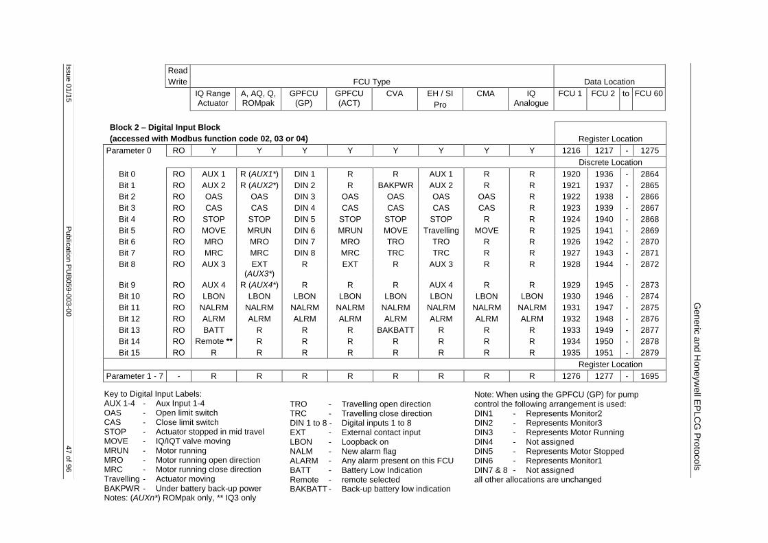
Issue 0
1/1
5
Public
atio
n P
UB
059
-003-0
0
47 o
f 96
Generic
and H
oneyw
ell E
PLC
G P
roto
cols
Read
Write
FCU Type
Data Location
IQ Range Actuator
A, AQ, Q, ROMpak
GPFCU (GP)
GPFCU (ACT)
CVA EH / SI
Pro
CMA IQ Analogue
FCU 1 FCU 2 to FCU 60
Block 2 – Digital Input Block
(accessed with Modbus function code 02, 03 or 04)
Register Location
Parameter 0 RO Y Y Y Y Y Y Y Y 1216 1217 - 1275
Discrete Location
Bit 0 RO AUX 1 R (AUX1*) DIN 1 R R AUX 1 R R 1920 1936 - 2864
Bit 1 RO AUX 2 R (AUX2*) DIN 2 R BAKPWR AUX 2 R R 1921 1937 - 2865
Bit 2 RO OAS OAS DIN 3 OAS OAS OAS OAS R 1922 1938 - 2866
Bit 3 RO CAS CAS DIN 4 CAS CAS CAS CAS R 1923 1939 - 2867
Bit 4 RO STOP STOP DIN 5 STOP STOP STOP R R 1924 1940 - 2868
Bit 5 RO MOVE MRUN DIN 6 MRUN MOVE Travelling MOVE R 1925 1941 - 2869
Bit 6 RO MRO MRO DIN 7 MRO TRO TRO R R 1926 1942 - 2870
Bit 7 RO MRC MRC DIN 8 MRC TRC TRC R R 1927 1943 - 2871
Bit 8 RO AUX 3 EXT (AUX3*)
R EXT R AUX 3 R R 1928 1944 - 2872
Bit 9 RO AUX 4 R (AUX4*) R R R AUX 4 R R 1929 1945 - 2873
Bit 10 RO LBON LBON LBON LBON LBON LBON LBON LBON 1930 1946 - 2874
Bit 11 RO NALRM NALRM NALRM NALRM NALRM NALRM NALRM NALRM 1931 1947 - 2875
Bit 12 RO ALRM ALRM ALRM ALRM ALRM ALRM ALRM ALRM 1932 1948 - 2876
Bit 13 RO BATT R R R BAKBATT R R R 1933 1949 - 2877
Bit 14 RO Remote ** R R R R R R R 1934 1950 - 2878
Bit 15 RO R R R R R R R R 1935 1951 - 2879
Register Location
Parameter 1 - 7 - R R R R R R R R 1276 1277 - 1695
Key to Digital Input Labels: AUX 1-4 - Aux Input 1-4 OAS - Open limit switch CAS - Close limit switch STOP - Actuator stopped in mid travel MOVE - IQ/IQT valve moving MRUN - Motor running MRO - Motor running open direction MRC - Motor running close direction Travelling - Actuator moving BAKPWR - Under battery back-up power Notes: (AUXn*) ROMpak only, ** IQ3 only
TRO - Travelling open direction TRC - Travelling close direction DIN 1 to 8 - Digital inputs 1 to 8 EXT - External contact input LBON - Loopback on NALM - New alarm flag ALARM - Any alarm present on this FCU BATT - Battery Low Indication Remote - remote selected BAKBATT - Back-up battery low indication
Note: When using the GPFCU (GP) for pump control the following arrangement is used: DIN1 - Represents Monitor2 DIN2 - Represents Monitor3 DIN3 - Represents Motor Running DIN4 - Not assigned DIN5 - Represents Motor Stopped DIN6 - Represents Monitor1 DIN7 & 8 - Not assigned all other allocations are unchanged

Pakscan P
3 w
ith P
720 M
od
ule
Mod
bus In
terfa
ce S
pecific
atio
n
48 o
f 96
Public
atio
n P
UB
059
-003-0
0
Issue 0
1/1
5
Read
Write
FCU Type
Data Location
IQ Range
Actuator
A, AQ, Q, ROMPAK
GPFCU (GP)
GPFCU (ACT)
CVA EH / SI
Pro
CMA IQ Analogue
FCU 1 FCU 2 to FCU 60
Block 3 – Alarm Block
(accessed with Modbus function code 02, 03 or 04)
Register Location
Parameter 0 RO Y Y Y Y Y Y Y Y 1696 1697 - 1755
Discrete Location
Bit 0 RO MEMF MEMF MEMF MEMF MEMF MEMF R MEMF 2880 2896 - 3824
Bit 1 RO COMMS COMMS COMMS COMMS COMMS COMMS COMMS COMMS 2881 2897 - 3825
Bit 2 RO LOCAL CNA R CNA LOCAL LOCAL LOCAL R 2882 2898 - 3826
Bit 3 RO POWR POWR POWR POWR POWR POWR POWR POWR 2883 2899 - 3827
Bit 4 RO WDOG WDOG WDOG WDOG WDOG WDOG WDOG WDOG 2884 2900 - 3828
Bit 5 RO MREL MREL R MREL MREL MREL MREL R 2885 2901 - 3829
Bit 6 RO THERM THERM R THERM THERM FAULT R R 2886 2902 - 3830
Bit 7 RO LSTOP LSTOP R LSTOP LSTOP LSTOP LSTOP R 2887 2903 - 3831
Bit 8 RO SFAIL SFAIL R SFAIL SFAIL SFAIL SFAIL R 2888 2904 - 3832
Bit 9 RO VOBS VOBS R VOBS VOBS VOBS VOBS R 2889 2905 - 3833
Bit 10 RO VJAM VJAM R VJAM VJAM VJAM R R 2890 2906 - 3834
Bit 11 RO AUXOR MOP R MOP R AUXOR R R 2891 2907 - 3835
Bit 12 RO VTT MCL R MCL RL VTT R R 2892 2908 - 3836
Bit 13 RO R MOPG R MOPG R R R R 2893 2909 - 3837
Bit 14 RO MMOVE MCLG R MCLG MMOVE MMOVE R R 2894 2910 - 3838
Bit 15 RO EOT EOT R EOT EOT EOT R R 2895 2911 - 3839
Register Location
Parameter 1 - 7 - R R R R R R R R 1756 1757 - 2175
Key to Alarm Labels: MEMF - RAM/ROM failure COMMS - Comms fail LOCAL - Actuator not in remote control CNA - Control not available POWR - Power on reset WDOG - Watchdog fail MREL - Monitor relay THERM - Thermostat trip
LSTOP - Local stop operated SFAIL - Start/stop fail VOBS - Valve obstructed VJAM - Valve jammed MMOVE - Manual valve movement MOP - Manual open MCL - Manual close MOPG - Manual opening
MCLG - Manual closing EOT - Motor running end of travel FAULT Fault relay, any fault present
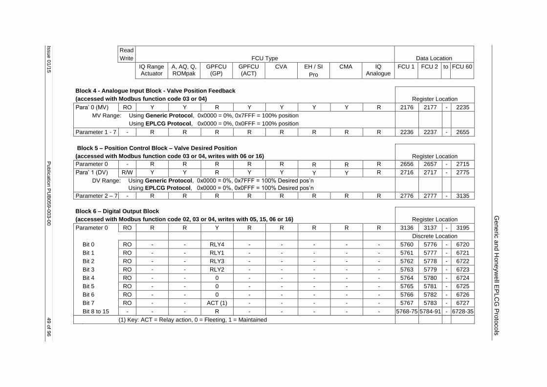
Issue 0
1/1
5
Public
atio
n P
UB
059
-003-0
0
49 o
f 96
Generic
and H
oneyw
ell E
PLC
G P
roto
cols
Read
Write
FCU Type
Data Location
IQ Range Actuator
A, AQ, Q, ROMpak
GPFCU (GP)
GPFCU (ACT)
CVA EH / SI
Pro
CMA IQ Analogue
FCU 1 FCU 2 to FCU 60
Block 4 - Analogue Input Block - Valve Position Feedback
(accessed with Modbus function code 03 or 04)
Register Location
Para’ 0 (MV) RO Y Y R Y Y Y Y R 2176 2177 - 2235
MV Range: Using Generic Protocol, 0x0000 = 0%, 0x7FFF = 100% position
Using EPLCG Protocol, 0x0000 = 0%, 0x0FFF = 100% position
Parameter 1 - 7 - R R R R R R R R 2236 2237 - 2655
Block 5 – Position Control Block – Valve Desired Position
(accessed with Modbus function code 03 or 04, writes with 06 or 16)
Register Location
Parameter 0 - R R R R R R R R 2656 2657 - 2715
Para’ 1 (DV) R/W Y Y R Y Y Y Y R 2716 2717 - 2775
DV Range: Using Generic Protocol, 0x0000 = 0%, 0x7FFF = 100% Desired pos’n
Using EPLCG Protocol, 0x0000 = 0%, 0x0FFF = 100% Desired pos’n
Parameter 2 – 7 - R R R R R R R R 2776 2777 - 3135
Block 6 – Digital Output Block
(accessed with Modbus function code 02, 03 or 04, writes with 05, 15, 06 or 16)
Register Location
Parameter 0 RO R R Y R R R R R 3136 3137 - 3195
Discrete Location
Bit 0 RO - - RLY4 - - - - - 5760 5776 - 6720
Bit 1 RO - - RLY1 - - - - - 5761 5777 - 6721
Bit 2 RO - - RLY3 - - - - - 5762 5778 - 6722
Bit 3 RO - - RLY2 - - - - - 5763 5779 - 6723
Bit 4 RO - - 0 - - - - - 5764 5780 - 6724
Bit 5 RO - - 0 - - - - - 5765 5781 - 6725
Bit 6 RO - - 0 - - - - - 5766 5782 - 6726
Bit 7 RO - - ACT (1) - - - - - 5767 5783 - 6727
Bit 8 to 15 - - - R - - - - - 5768-75 5784-91 - 6728-35
(1) Key: ACT = Relay action, 0 = Fleeting, 1 = Maintained
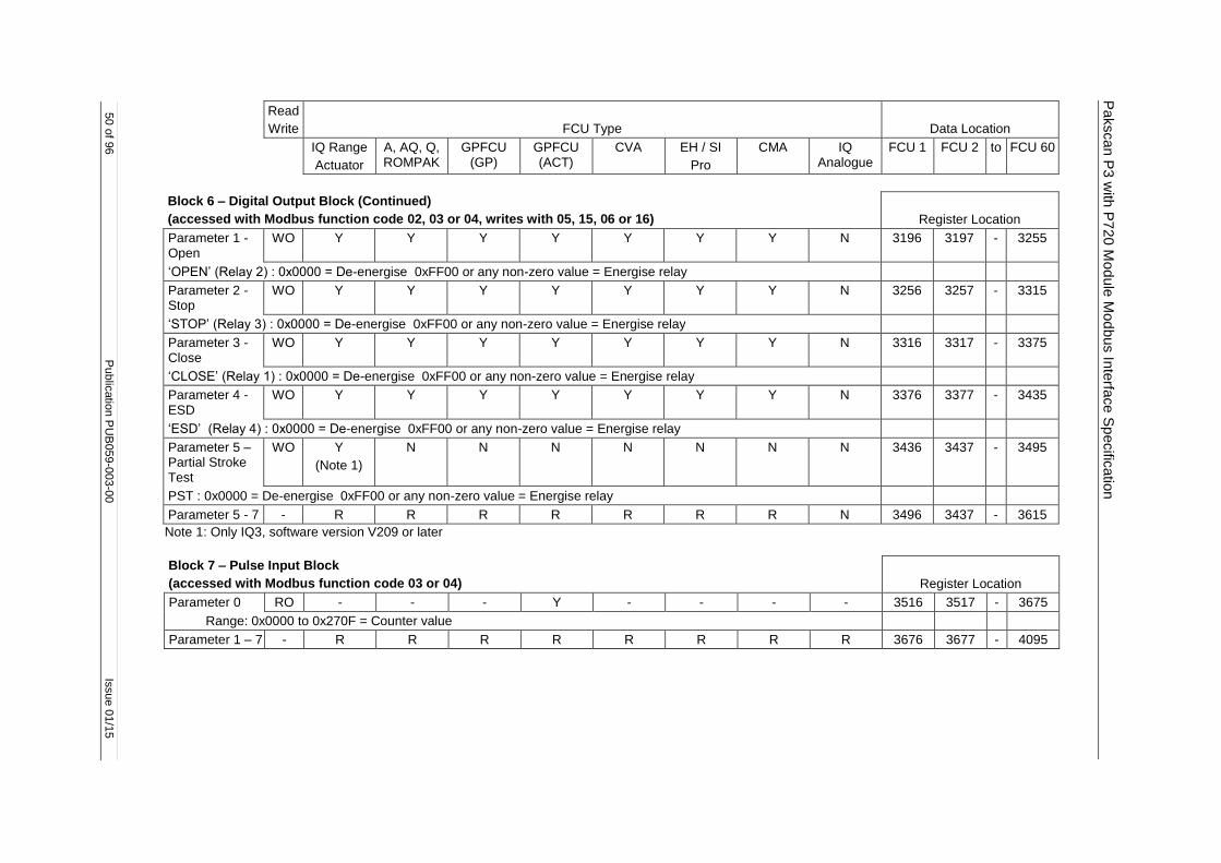
Pakscan P
3 w
ith P
720 M
od
ule
Mod
bus In
terfa
ce S
pecific
atio
n
50 o
f 96
Public
atio
n P
UB
059
-003-0
0
Issue 0
1/1
5
Read
Write
FCU Type
Data Location
IQ Range
Actuator
A, AQ, Q, ROMPAK
GPFCU (GP)
GPFCU (ACT)
CVA EH / SI
Pro
CMA IQ Analogue
FCU 1 FCU 2 to FCU 60
Block 6 – Digital Output Block (Continued)
(accessed with Modbus function code 02, 03 or 04, writes with 05, 15, 06 or 16)
Register Location
Parameter 1 - Open
WO Y Y Y Y Y Y Y N 3196 3197 - 3255
‘OPEN’ (Relay 2) : 0x0000 = De-energise 0xFF00 or any non-zero value = Energise relay
Parameter 2 - Stop
WO Y Y Y Y Y Y Y N 3256 3257 - 3315
‘STOP’ (Relay 3) : 0x0000 = De-energise 0xFF00 or any non-zero value = Energise relay
Parameter 3 - Close
WO Y Y Y Y Y Y Y N 3316 3317 - 3375
‘CLOSE’ (Relay 1) : 0x0000 = De-energise 0xFF00 or any non-zero value = Energise relay
Parameter 4 - ESD
WO Y Y Y Y Y Y Y N 3376 3377 - 3435
‘ESD’ (Relay 4) : 0x0000 = De-energise 0xFF00 or any non-zero value = Energise relay
Parameter 5 – Partial Stroke Test
WO Y
(Note 1)
N N N N N N N 3436 3437 - 3495
PST : 0x0000 = De-energise 0xFF00 or any non-zero value = Energise relay
Parameter 5 - 7 - R R R R R R R N 3496 3437 - 3615
Note 1: Only IQ3, software version V209 or later
Block 7 – Pulse Input Block
(accessed with Modbus function code 03 or 04)
Register Location
Parameter 0 RO - - - Y - - - - 3516 3517 - 3675
Range: 0x0000 to 0x270F = Counter value
Parameter 1 – 7 - R R R R R R R R 3676 3677 - 4095
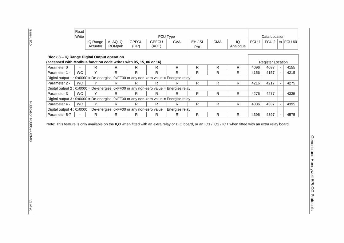
Issue 0
1/1
5
Public
atio
n P
UB
059
-003-0
0
51 o
f 96
Generic
and H
oneyw
ell E
PLC
G P
roto
cols
Read
Write
FCU Type
Data Location
IQ Range Actuator
A, AQ, Q, ROMpak
GPFCU (GP)
GPFCU (ACT)
CVA EH / SI
Pro
CMA IQ Analogue
FCU 1 FCU 2 to FCU 60
Block 8 – IQ Range Digital Output operation
(accessed with Modbus function code writes with 05, 15, 06 or 16)
Register Location
Parameter 0 - R R R R R R R R 4096 4097 - 4155
Parameter 1 - WO Y R R R R R R R 4156 4157 - 4215
Digital output 1 : 0x0000 = De-energise 0xFF00 or any non-zero value = Energise relay
Parameter 2 - WO Y R R R R R R R 4216 4217 - 4275
Digital output 2 : 0x0000 = De-energise 0xFF00 or any non-zero value = Energise relay
Parameter 3 - WO Y R R R R R R R 4276 4277 - 4335
Digital output 3 : 0x0000 = De-energise 0xFF00 or any non-zero value = Energise relay
Parameter 4 - WO Y R R R R R R R 4336 4337 - 4395
Digital output 4 : 0x0000 = De-energise 0xFF00 or any non-zero value = Energise relay
Parameter 5-7 - R R R R R R R R 4396 4397 - 4575
Note: This feature is only available on the IQ3 when fitted with an extra relay or DIO board, or an IQ1 / IQ2 / IQT when fitted with an extra relay board.
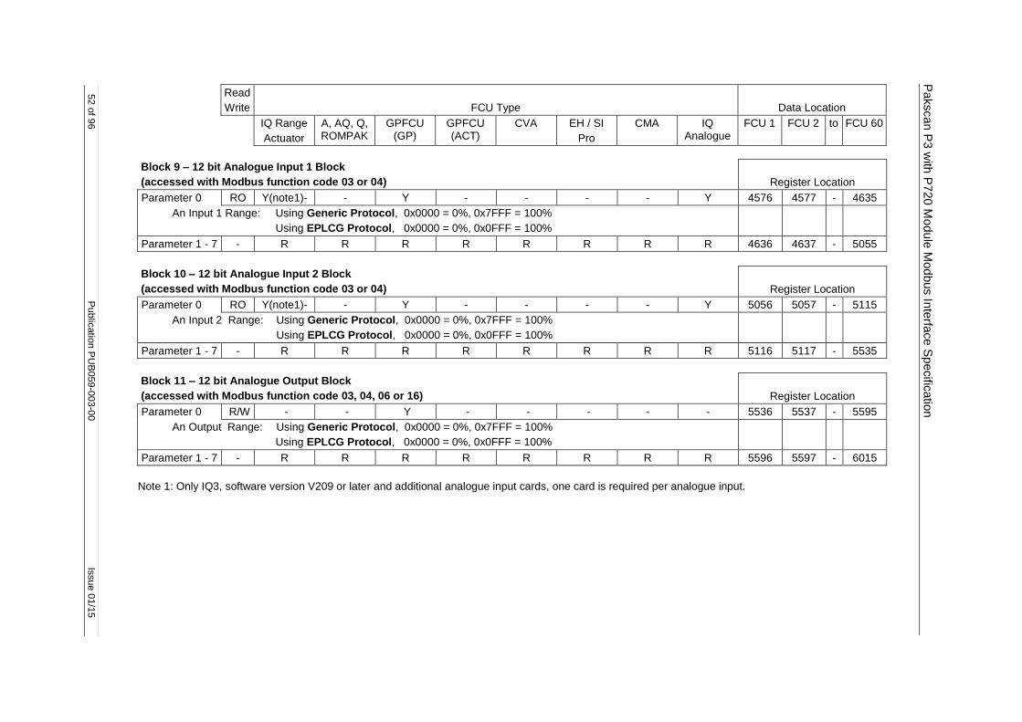
Pakscan P
3 w
ith P
720 M
od
ule
Mod
bus In
terfa
ce S
pecific
atio
n
52 o
f 96
Public
atio
n P
UB
059
-003-0
0
Issue 0
1/1
5
Read
Write
FCU Type
Data Location
IQ Range
Actuator
A, AQ, Q, ROMPAK
GPFCU (GP)
GPFCU (ACT)
CVA EH / SI
Pro
CMA IQ Analogue
FCU 1 FCU 2 to FCU 60
Block 9 – 12 bit Analogue Input 1 Block
(accessed with Modbus function code 03 or 04)
Register Location
Parameter 0 RO Y(note1)- - Y - - - - Y 4576 4577 - 4635
An Input 1 Range: Using Generic Protocol, 0x0000 = 0%, 0x7FFF = 100%
Using EPLCG Protocol, 0x0000 = 0%, 0x0FFF = 100%
Parameter 1 - 7 - R R R R R R R R 4636 4637 - 5055
Block 10 – 12 bit Analogue Input 2 Block
(accessed with Modbus function code 03 or 04)
Register Location
Parameter 0 RO Y(note1)- - Y - - - - Y 5056 5057 - 5115
An Input 2 Range: Using Generic Protocol, 0x0000 = 0%, 0x7FFF = 100%
Using EPLCG Protocol, 0x0000 = 0%, 0x0FFF = 100%
Parameter 1 - 7 - R R R R R R R R 5116 5117 - 5535
Block 11 – 12 bit Analogue Output Block
(accessed with Modbus function code 03, 04, 06 or 16)
Register Location
Parameter 0 R/W - - Y - - - - - 5536 5537 - 5595
An Output Range: Using Generic Protocol, 0x0000 = 0%, 0x7FFF = 100%
Using EPLCG Protocol, 0x0000 = 0%, 0x0FFF = 100%
Parameter 1 - 7 - R R R R R R R R 5596 5597 - 6015
Note 1: Only IQ3, software version V209 or later and additional analogue input cards, one card is required per analogue input.

Issue 0
1/1
5
Public
atio
n P
UB
059
-003-0
0
53 o
f 96
Generic
and H
oneyw
ell E
PLC
G P
roto
cols
Read
Write
FCU Type
Data Location
IQ Range Actuator
A, AQ, Q, ROMpak
GPFCU (GP)
GPFCU (ACT)
CVA EH / SI
Pro
CMA IQ Analogue
FCU 1 FCU 2 to FCU 60
Block 12 – Historical Torque Profile – Opening Direction
(accessed with Modbus function code 03 or 04)
Register Location
8 torque (For EH / SI pressure.) values related to valve position across the valve stroke. Position 0 and 100% are not used as these may be set to full torque for a torque seating valve. Torque readings are available for 6%, 19%, 31%, 44%, 56%, 69%, 81%, and 94% positions. Parameters 1-7 contain this data for the OPENING direction of travel - note they only update if a complete stroke of the valve is made and contain the last profile.
All are ranged as : Using Generic Protocol, 0x0000 = 0% rated torque, 0x7FFF = 120% rated torque
Using EPLCG Protocol, 0x0000 = 0% rated torque, 0x0FFF = 120% rated torque
Para’ 0 - 6% RO Y - - - Y Y - - 6016 6017 - 6075
Para’ 1 - 19% RO Y - - - Y Y - - 6076 6077 - 6135
Para’ 2 - 31% RO Y - - - Y Y - - 6136 6137 - 6195
Para’ 3 - 44% RO Y - - - Y Y - - 6196 6197 - 6255
Para’ 4 - 56% RO Y - - - Y Y - - 6256 6257 - 6315
Para’ 5 - 69% RO Y - - - Y Y - - 6316 6317 - 6375
Para’ 6 - 81% RO Y - - - Y Y - - 6376 6377 - 6435
Para’ 7 - 94% RO Y - - - Y Y - - 6436 6437 - 6495
Block 13 – Historical Torque Profile – Closing Direction
(accessed with Modbus function code 03 or 04)
Register Location
8 torque (For EH / SI pressure.) values related to valve position across the valve stroke. Position 0 and 100% are not used as these may be set to full torque for a torque seating valve. Torque readings are available for 6%, 19%, 31%, 44%, 56%, 69%, 81%, and 94% positions. Parameters 1-7 contain this data for the CLOSING direction of travel - note they only update if a complete stroke of the valve is made and contain the last profile.
All are ranged as : Using Generic Protocol, 0x0000 = 0% rated torque, 0x7FFF = 120% rated torque
Using EPLCG Protocol, 0x0000 = 0% rated torque, 0x0FFF = 120% rated torque
Para’ 0 - 6% RO Y - - - Y Y - - 6496 6497 - 6555
Para’ 1 - 19% RO Y - - - Y Y - - 6556 6557 - 6615
Para’ 2 - 31% RO Y - - - Y Y - - 6616 6617 - 6675
Para’ 3 - 44% RO Y - - - Y Y - - 6676 6677 - 6735
Para’ 4 - 56% RO Y - - - Y Y - - 6736 6737 - 6795
Para’ 5 - 69% RO Y - - - Y Y - - 6796 6797 - 6855
Para’ 6 - 81% RO Y - - - Y Y - - 6856 6857 - 6915
Para’ 7 - 94% RO Y - - - Y Y - - 6916 6917 - 6975

Pakscan P
3 w
ith P
720 M
od
ule
Mod
bus In
terfa
ce S
pecific
atio
n
54 o
f 96
Public
atio
n P
UB
059
-003-0
0
Issue 0
1/1
5
Read
Write
FCU Type
Data Location
IQ Range
Actuator
A, AQ, Q, ROMPAK
GPFCU (GP)
GPFCU (ACT)
CVA EH / SI
Pro
CMA IQ Analogue
FCU 1 FCU 2 to FCU 60
Block 14 – Instantaneous Torque
(accessed with Modbus function code 03 or 04)
Register Location
Parameter 0 RO Y - - - Y Y - - 6976 6977 - 7035
Inst. Torque Range: Using Generic Protocol, 0x0000 = 0%, 0x7FFF = 120%
Using EPLCG Protocol, 0x0000 = 0%, 0x0FFF = 120%
For EH / SI this value represents pressure.
Parameter 1 - 3 - R R R R R R R R 7036 7034 - 7215
Parameter 4 RO Y - - - Y Y - - 7216 7217 - 7275
Torque Profile Counters
Data Bits 8-15 = Opening Torque Profile count
Data Bits 0-7 = Closing Torque Profile count
Parameter 5 - 7 - R R R R R R R R 7276 7277 - 7455
Block 15 to 31 – Reserved
Register Location
Block 15 Para 0 -
Block 31 Para 7
- R R R R R R R R 7456 7457 - 15615
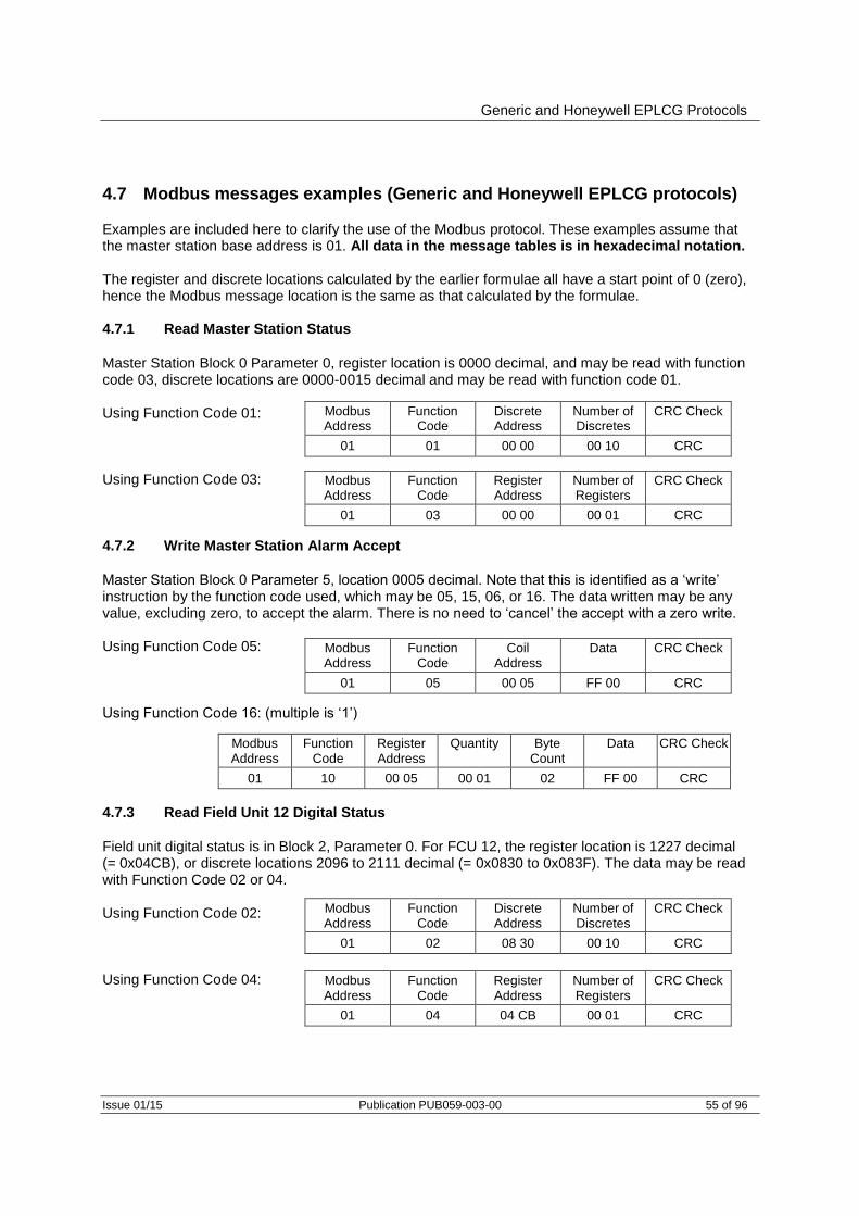
Generic and Honeywell EPLCG Protocols
Issue 01/15 Publication PUB059-003-00 55 of 96
4.7 Modbus messages examples (Generic and Honeywell EPLCG protocols)
Examples are included here to clarify the use of the Modbus protocol. These examples assume that the master station base address is 01. All data in the message tables is in hexadecimal notation. The register and discrete locations calculated by the earlier formulae all have a start point of 0 (zero), hence the Modbus message location is the same as that calculated by the formulae. 4.7.1 Read Master Station Status
Master Station Block 0 Parameter 0, register location is 0000 decimal, and may be read with function code 03, discrete locations are 0000-0015 decimal and may be read with function code 01. Using Function Code 01: Using Function Code 03: 4.7.2 Write Master Station Alarm Accept
Master Station Block 0 Parameter 5, location 0005 decimal. Note that this is identified as a ‘write’ instruction by the function code used, which may be 05, 15, 06, or 16. The data written may be any value, excluding zero, to accept the alarm. There is no need to ‘cancel’ the accept with a zero write. Using Function Code 05: Using Function Code 16: (multiple is ‘1’) 4.7.3 Read Field Unit 12 Digital Status
Field unit digital status is in Block 2, Parameter 0. For FCU 12, the register location is 1227 decimal (= 0x04CB), or discrete locations 2096 to 2111 decimal (= 0x0830 to 0x083F). The data may be read with Function Code 02 or 04. Using Function Code 02: Using Function Code 04:
Modbus Address
Function Code
Discrete Address
Number of Discretes
CRC Check
01 01 00 00 00 10 CRC
Modbus Address
Function Code
Register Address
Number of Registers
CRC Check
01 03 00 00 00 01 CRC
Modbus Address
Function Code
Coil Address
Data CRC Check
01 05 00 05 FF 00 CRC
Modbus Address
Function Code
Register Address
Quantity Byte Count
Data CRC Check
01 10 00 05 00 01 02 FF 00 CRC
Modbus Address
Function Code
Discrete Address
Number of Discretes
CRC Check
01 02 08 30 00 10 CRC
Modbus Address
Function Code
Register Address
Number of Registers
CRC Check
01 04 04 CB 00 01 CRC

Pakscan P3 with P720 Module Modbus Interface Specification
56 of 96 Publication PUB059-003-00 Issue 01/15
4.7.4 Read Field Unit 62 Digital Status
Field Unit 62 is found in Modbus Address Base + 1 = 02 as it is above number 60. The data is located in Block 2, Parameter 0. For FCU 62 the register location is as for FCU 02, 1217 decimal (= 0x04C1), and discrete locations 1936 to 1951 decimal (= 0x0790 to 0x079F). Using Function Code 02: Using Function Code 04: 4.7.5 Read Digital Status from 60 Field Units, Addresses 121 to 180
Modbus Address = Base + 2 = 03. Data is in Block 2 Parameter 0. FCU 1 data starts in register 1216 decimal (= 0x04C0). Using Function Code 04: 4.7.6 Energise Command to OPEN relay of Field Unit 4
The OPEN relay for FCU 4 is located in Block 6 Parameter 1, register location 3199 decimal (= 0x0C7F). Either Function code 05 or 06 can be used, but the location to be written to is always the register number. Using Function Code 05: Using Function Code 06: 4.7.7 Write Desired Valve Position for FCU 26 to be 50%
The DV data is written to Block 5 Parameter 1, register 2741 decimal (= 0x0AB5) for FCU 26. With Generic Protocol, 50% is 0x3FFF and with EPLCG Protocol, 50% is 0x07FF. Using Function Code 06 and Generic Protocol
Using Function Code 06 and EPLCG Protocol
Modbus Address
Function Code
Discrete Address
Number of Discretes
CRC Check
02 02 07 90 00 10 CRC
Modbus Address
Function Code
Register Address
Number of Registers
CRC Check
02 04 04 C1 00 01 CRC
Modbus Address
Function Code
Register Address
Number of Registers
CRC Check
03 04 04 C0 00 3C CRC
Modbus Address
Function Code
Address Data CRC Check
01 05 0C 7F FF 00 CRC
Modbus Address
Function Code
Address Data CRC Check
01 06 0C 7F FF 00 CRC
Modbus Address
Function Code
Address Data CRC Check
01 06 0A B5 3F FF CRC
Modbus Address
Function Code
Address Data CRC Check
01 06 0A B5 07 FF CRC

Yokogawa and Honeywell SI Protocols
Issue 01/15 Publication PUB059-003-00 57 of 96
5 YOKOGAWA AND HONEYWELL SI PROTOCOL INTERFACE SPECIFICATION
This section describes the two protocols that pack the field unit data in the tightest way. This allows the host system to minimise the data traffic to and from the master station. The tables give register and discrete locations in the master station from which the data may be read. The Yokogawa protocol is recommended when interfacing between a Pakscan master station and a Yokogawa Centum CS and ACM11 interface card, Centum XL, EFCD gateway and RS4 cards, or similar system where the data packing is suitable. The protocol has been tested by Yokogawa in Japan, Holland, and Singapore and found to successfully connect the Pakscan and Yokogawa systems together. The protocol allows a standard Yokogawa SI22 faceplate to be used for the screen displays associated with motor operated valves. The Honeywell SI protocol is recommended for connection between the Pakscan master station and the Honeywell SI gateway. Honeywell has tested and approved the SI version for connecting the Pakscan system to a Honeywell TDC 3000 with an Advanced Process Manager and Serial Interface Gateway, or similar system where the data packing is suitable. On the Pakscan 3 Current Loop Option Module select 'YOKOGAWA' for the Yokogawa configuration of the data base or ‘HONEYWELL SI’ for the SI version of the data base: the difference between these two choices is in the analogue data scaling only. Yokogawa uses 16-bit 2’s complement and Honeywell SI uses an integer value in the register, all locations for the data are identical. Care must be taken to ensure that the correct protocol is selected for the application concerned. The master station responds as a Modbus Slave to messages from the host. Each master station responds to a single Modbus address. The serial ports can each use different data bases, whilst the two Ethernet ports must both use the same data base and protocol The master station maintains a data base covering all its connected field units, and the host reads this data without the need to access field units directly. The master station performs the functions of Data Concentrator, Protocol Converter, and 2-wire current loop master. Within the field units data is organised in blocks. The data base locations listed in this section are the spaces from which and to which this data is moved.
5.1 Modbus unit address (Yokogawa and Honeywell SI protocols)
The first byte of all Modbus message frames is the Modbus Address byte. Modbus supports 248 addresses, of which value 0 is always allocated for Broadcast messages. This leaves 247 addresses for use by connected devices on the Modbus data link.
Modbus Address
Function Code
Register or Discrete Address
Number of Registers or
Bits
Data Field
CRC Check
8 bits 8 bits 16 bits 16 bits N bits 16 bits
Fig 21: Modbus transaction format

Pakscan P3 with P720 Module Modbus Interface Specification
58 of 96 Publication PUB059-003-00 Issue 01/15
Modbus
Address
0 Broadcast message Master station
data base
1
|
247
P3/P3F Master station and up to 240 field units
on current loop
Master station
data
Field unit
data
Each Pakscan 3 Current Loop Option Card occupies a single Modbus address in which all the data relating to itself and the connected field units is located. Modbus 'Read' requests return field unit data from the data base in the appropriate master station; Modbus 'Write' requests are translated into write commands which are sent to the field unit concerned.
Modbus Address Responding Master Station Interpretation
0
1
2
|
247
All
1
2
|
247
Modbus Broadcast
Data base access
Data base access
|
Data base access
Fig 23: Modbus addressing for master stations
Fig 22: Modbus unit address structure – Yokogawa and Honeywell SI protocol

Yokogawa and Honeywell SI Protocols
Issue 01/15 Publication PUB059-003-00 59 of 96
5.2 Modbus function code support (Yokogawa and Honeywell SI protocols)
Details of Request and Reply formats are contained in the Modbus Reference Guide. The following section deals with how Pakscan 3 master stations interpret the commands. Fig 24 lists the supported Modbus commands.
Function Code
Modbus Name Addressing
01
02
03
04
05
06
08
15
16
Read coil status
Read input status
Read holding registers
Read input registers
Force single coil
Preset single register
Loopback diagnostic test
Force multiple coils
Preset multiple registers
Discrete
Discrete
Register
Register
Discrete
Register
Discrete
Register
Error code Meaning
01
02
03
06
Illegal function code or incorrect message length
Illegal data address (Register address invalid)
Illegal data value
Slave Device Busy
Within the master station there is one data base associated with each serial comms port and one shared between the two Ethernet ports. All data read commands access these data bases.
Function Code 01 - Read Coil Status Requests
Where the gateway is set up to read the data from the open or close coils, for example prior to writing data, this is permitted by the master station. However the coils do not physically exist and the data read back by the host is the current status of the Open and Close limit switch in the actuator (OAS for an Open command and CAS for a Close command). These signals may not reflect the state of the command coil. For example the actuator may have been opened by a system command to the open coil and then closed manually. The coil for open would be expected to be ‘on’, but the actuator will report the close coil as being ‘on’ since CAS will be present, and the open coil as being ‘off’. In addition for actuator control all the write signals become pulsed outputs at the field unit and the actuator responds to these pulse commands itself.
Fig 24: Modbus function codes and error codes

Pakscan P3 with P720 Module Modbus Interface Specification
60 of 96 Publication PUB059-003-00 Issue 01/15
Function Code 02 - Read Input Status Requests
Any Input Status data within the master station may be read with a Code 02 Read request. The returned data will be valid for the discrete locations chosen.
Function Code 03 - Read Holding Register Requests
Holding registers are used for the location of Output registers. In the case of Pakscan systems these output registers are used either to position a valve or for setting an analogue output. Where the gateway is set up to read the data in a Holding register, for example prior to writing data, the master station permits this. However, the data read back by the host may not be true. In the case of reading the state of an output (holding) register the master station may not directly reflect the current position of the attached field unit or actuator since the actuator may have been moved manually or by a digital command since the analogue position was last sent. The data read may not be valid, though it will be the last state written.
Function Code 04 - Read Input Register Requests
Any register data within the master station may be read with a Code 04 Read request. The returned data will be valid for the discrete locations chosen.
Function Code 05 and 06 - Force Single Coil, Preset Single Register
If a Write request is to a discrete coil or register associated with the master station, then data is written directly to that coil or register. If the Write request is to a discrete coil or register associated with a Field Unit, then the information contained in the message is translated into a command that a field unit understands. The command is then sent to the field unit over the current loop network. The rate at which instructions are sent must not exceed the rate at which they can be sent on to the field units. The sequence of events is: (1) - Write command received by the master station. (2) - Response sent back to Host (3) - Write message sent to Field Unit A good response to the Host indicates that the request was received correctly, the message length is acceptable, and that the addressed Field Unit is on-line. It does not indicate that the Write to the Field Unit was successful. A successful write is confirmed some time later when new data is reported as a change in the main data base. If commands are written at too high a rate then the current loop network is prevented from collecting data from the field units and the system will appear to slow down. The Command Filter provides some protection against too high a frequency of writing commands. It causes the system to ignore duplicated commands to the same field unit if the duplicate is within the time setting for the filter.
Yokogawa and Honeywell SI Protocols
Issue 01/15 Publication PUB059-003-00 61 of 96
Code 08 - Loopback Diagnostic Test
The purpose of the Loopback Test is to test the communication system between the master station and the gateway. The master station supports this test when used with diagnostic code 00, Return Query Data. No other diagnostic test codes are supported.
Code 15 and 16 - Force Multiple Coils, Preset Multiple Registers
If a Write request is to discrete coils or registers associated with the master station, then data is written directly to those coils or registers. If the Write request is to discrete coils or registers associated with Field Units, then the information contained in the message is translated into a commands that field units understand. The command is then sent to the field unit over the current loop network. The master station is able to accept a single transaction multiple write message containing information to be written to a maximum of 123 registers. These instructions are then passed to a queue for onward transmission over the current loop network. The rate at which instructions are sent must not exceed the rate at which they can be sent on to the field units. If commands are written at too high a rate then the current loop network is prevented from collecting data from the field units and the system will appear to slow down. The Command Filter provides some protection against too high a frequency of writing commands. It causes the system to ignore duplicated commands to the same field unit if the duplicate is within the time setting for the filter. In the case of actuator control there is never a need to write to a coil to turn it off as the output is always treated as a pulse. The DCS control should be arranged for the outputs to be pulse type. If this is not done the communication on the current loop network will carry unnecessary control commands to ‘turn off’ coils that are already off.
Error Codes 01, 02 and 06
Error code 01 will be presented back to the host if the function code in the data message is not one of those supported by the master station or the message length is not as expected. Error code 02 will be presented back to the host if the Data Address is illegal; or if the write command is a multiple write (code 15 or 16) where the number of coils or registers exceeds the amount acceptable. Error code 03 will be presented back to the host if the value contained in the data query field is illegal. Error code 06 will also be sent back to the host if the master station has insufficient buffer space to handle the write request to coils or registers in a single transaction. Buffer space will become free as the writes are issued to the loop and field units.
Pakscan P3 with P720 Module Modbus Interface Specification
62 of 96 Publication PUB059-003-00 Issue 01/15
5.3 Data base access (Yokogawa and Honeywell SI protocols)
The data base is accessed by use of the Modbus address structure using Register Numbers or Discrete Numbers in accordance with the Modbus standard. The data base contains information collected from field units and is the data actually in the master station. Data transfers to and from the field units are under the control of the Pakscan 3 master station option card. 5.3.1 Data Organisation
The data base comprises a series of records organised in accordance with the Modbus documentation. Messages with function codes 01 to 06, 15 and 16 indicate specifically which locations in the data base are to be accessed. Function Codes 01, 05, and 15 refer to coils 0XXXX Function Code 02 refers to discrete inputs 1XXXX Function Code 04 refers to read only registers 3XXXX Function Codes 03, 06, and 16 refer to registers 4XXXX Coils are used for digital outputs. The status of maintained digital outputs should be read from discrete status inputs and not from the coil itself. Data read back from a coil may not be valid. Registers are used for all multiple bit signals (analogues and counters). Some are protected and may only be read. Data read back from a Holding register with code 03 will contain the last data written to that coil. It may not reflect the actual status of the register in the field unit. The data in each record is listed in the following sections for both master stations for field units. 5.3.2 Data Interchange Requests
Data may be interchanged between the host and the master station data base using Modbus Register or Discrete Numbers.
5.4 Notes on the use of the Yokogawa and Honeywell SI Modbus protocol
Normally the Modbus host will be set up to cyclically read data representing key variables of the master station and field units. It can do this using Read Input Register function code 04, and Read Discrete Status function code 02. In addition the gateway may be set to use function code 01 to read Output Coils prior to a write (05) or code 03 to read Holding Registers prior to a write (06). Register and Discrete address numbers referred to in the standard Modbus documentation all start from number 1, though the actual data request on the data link takes its start as 0. The Modbus host software may need to be configured with addresses that are 1 less than those listed in the tables following. This is due to the Host regarding addresses as starting from 0, not 1. The actual method used by the gateway is specified in its documentation. The discrete and register numbers listed in the tables all start from '1', register 40001 would be referenced as 0000 in the serial transaction.

Yokogawa and Honeywell SI Protocols
Issue 01/15 Publication PUB059-003-00 63 of 96
The data base is arranged to provide maximum efficiency in the use of the gateway space available and reading a group of registers in one transaction is more efficient than reading one register at a time. The Honeywell SI, because of the link to the APM Arrays may be easily set to collect multiple data in a transaction. The Yokogawa gateway should be organised to use efficient data transfer at all times. Note that the discrete bits may be moved in a minimum of 16 bits to the card working space. The master station includes Alarm Accept logic with respect to field unit alarms. Alarms from field units are automatically accepted by the master station (so the field unit can clear its alarm latches) and latched within the master station. These alarms must be read by the Host and then accepted (with an Alarm Accept write to coil 32) before they can clear. 5.4.1 Suggested Scan Cycle
The Host should be configured to scan data from the master station in the following order: Read Alarm Status Read Digital Status Perform Alarm Accept (only strictly necessary if any New Alarms have occurred) Read Analogue Status (if any analogue data is to be read) Commands to Field Units may be fitted in as required. In some applications it may be desirable to scan some items e.g. analogues, less frequently than others. This is perfectly acceptable. Within the master station area of the data base there are common alarm bits for loop fault, field unit fault and actuator fault. These may be used as a quick way of checking for new alarms. 5.4.2 Writing to Coils
When writing to a coil the data field to turn off the coil has to be 0x0000. As the most common device connected is an actuator whose action is controlled by a pulse output there is often no need to turn off a coil that has previously been turned on. The output command from the DCS should, where possible, use a pulse type output. When writing to a coil the data field to turn on the coil may be 0xFF00 or any other non zero value. 5.4.3 Readback of Holding Registers
The master station supports the reading of the data in the Holding Registers. This data may not accurately reflect the state of the actuator as it could have been moved manually since the data was written. The data is a 2’s complement 16 bit value (0x0000 – 0x7FFF) in the case of the Yokogawa protocol or a signed integer value (0-0x0064) in the case of the Honeywell SI. It is calculated from the actual value used in the data transaction over the current loop network to the field unit. When ‘read back’ this value may differ by 1 digit due to rounding errors in the calculation. The value sent to the field unit when the register was written will be true. To establish the actual valve position the Input Register relating to the field unit Measured Value should be read.
Pakscan P3 with P720 Module Modbus Interface Specification
64 of 96 Publication PUB059-003-00 Issue 01/15
5.4.4 Alarm Handling
The two serial communication ports on the master station are each served by their own independent data base and alarm handling. The two Ethernet ports share a third independent data base. The handling of alarms on one port does not reflect on the alarms of any of the other port. In the data base there is a group of 16 bits (bits 13 to 28) of data defined as the 'Alarm Block' for each field unit (for example 'COMMS' is an alarm bit). Similarly there are System Alarms as listed in the master station data section, for example 'RAM test fail'. These data bits will all be latched by the master station if they should actually occur. The master station will therefore capture a transient alarm and keep it in its data base ready for the host to read it. Any latched alarm from these data areas will only be reset on three subsequent conditions. Firstly the alarm bit must read by the host, secondly the alarm bit must be accepted by the host (this is done by issuing an 'Alarm Accept'), and finally the source of the alarm itself must return to normal. An example of the sequence would be: Consider an Actuator Thermostat.
1. Thermostat gets hot and trips. 2. Host reads data bit (bit 19) for the thermostat for this actuator 3. Host issues Alarm Accept; this is registered by the system as applicable to the
Thermostat Trip alarm. 4. The data bit remains set until the actuator cools down. 5. Once cooled below the trip point the data bit returns to normal.
If the host does not read the thermostat bit for this field unit then the bit will remain set for all time, even after the actuator cools down. In addition, if the host does not read this bit any Alarm Accept will not allow the alarm to reset itself. Any alarm bit must be read before it is able to be accepted. Even if the alarms are read infrequently, the above procedure guarantees that any alarm from the alarm block will be registered by the host. In addition to the alarm data for each field unit there is a 'Status Block'. These status locations also contain information about the presence (or absence) of alarms in the Alarm Block.
‘Alarm’ Bit (bit 12)
For each field unit the 'Alarm' bit will be present if any of the source signals used to set bits in the Alarm block are present. Notice that the Alarm bit is an OR function of any alarm before the latch for that alarm. The 'Alarm' bit is latched and will not clear until it has been read, accepted and the source of the alarm has returned to normal. In the example of the thermostat, the 'Alarm' bit will be set when the thermostat is initially tripped.

Yokogawa and Honeywell SI Protocols
Issue 01/15 Publication PUB059-003-00 65 of 96
‘New Alarm’ Bit (bit 11)
For each field unit, 'New Alarm' will be present every time a new alarm is detected as occurring in the field unit. However, every time an Alarm Accept is issued this data bit will be reset even if the alarm itself is still present. The purpose of this bit is to indicate to the Host that there is a new alarm to be read from the alarm block.
System Common Alarms
In the master station bit 10250 will be set if any field unit has its own 'Alarm' bit set. Thus the 'Common Field Unit Alarm' is set whilst any one field unit has an input actually in alarm. Bit 10251 contains a similar common data bit derived from the actuator 'Monitor Relay' source signals. 5.4.5 Use of Alarm Bits
The host may be configured to read as many, or all, of the alarm block data bits as required. Those that are not being used will probably 'fill up' as alarms over the course of operating the system. For the alarms that are used they will individually appear in the data locations being read, and by means of the Alarm Accept process will transfer to the host. They will also reset themselves as they return to normal provided they are read and accepted. The 'Alarm' bit will inform the host that any alarm is present, even those not normally being identified by the host as relevant. This bit may be used by the host as a flag that an alarm is currently present on a field unit. The 'New Alarm' bit may be used to indicate to the host that an alarm reading process is required, or that an alarm accept is required. The New Alarm will by its very nature disappear once the Accept is issued irrespective of the actual plant status as it has to be available for each 'new' alarm.

Pakscan P3 with P720 Module Modbus Interface Specification
66 of 96 Publication PUB059-003-00 Issue 01/15
5.5 Master station data base (Yokogawa and Honeywell SI protocols)
5.5.1 Master Station Records
The discrete and register numbers listed in the tables all start from '1', for example discrete input 10001 would be referenced as 0000 in the serial transaction and not 0001.
Digital Inputs – Read Only Data (accessed with Modbus function code 02)
Individual Bits - Discrete Locations (1 bit per)
Location Description Location Description
System Alarms
System status and flags
10001 to 10240 Reserved 10248 Loopback in progress
10241 RAM test fail 10249 Loopback in use
10242 ROM test fail 10250 Common Field Unit alarm
10243 Power On Reset 10251 Common Actuator alarm
10244 Watchdog fail 10252 Master station A (Main) ok
10245 Auto loopback 10253 Master station B (Standby) ok
10246 Reserved 10254 Communicating to:
0 = Master station A (Left),
1 = Master station B (Right)
10247 Reserved 10255 1 = Primary (In Use), 0 = Standby (Out of Use)
Digital Outputs – Write function (accessed with Modbus function code 05 and 15)
Individual Bits - Discrete Locations (1 bit per) When writing to a location the data field should comply with the Modbus instructions, although writing any value (including zero) to these locations will cause the action to occur.
Function Action Location Description
Global ESD Trigger write to trigger ESD 0001 ESD
Change Master write to change over 0015 Change Master
System reconfiguration write to trigger 0016 Reset Loop
System/Comms Alarm Accept write to accept 0032 Alarm Accept

Yokogawa and Honeywell SI Protocols
Issue 01/15 Publication PUB059-003-00 67 of 96
5.6 Field unit data base (Yokogawa and Honeywell SI protocols)
The field unit data base is organised to present the same information from each sequential field unit address in adjacent record entries. This general rule is broken only by the signals indicating valve open (OAS) and valve closed (CAS), and the commands to 'Open' and 'Close' the valves. These records are located adjacent to one another in pairs for each field unit. As the field units may be of differing types, a Bit No., Relay No. or register description identifier is attached, together with its meaning for each record group. The different Bit No., Relay No. and register meanings are also listed for the different field unit types at the end of this section. 5.6.1 Digital Inputs (Field Units)
The discrete and register numbers listed in the tables all start from '1', discrete input 10001 would be referenced as 0000 in the serial transaction and not 0001.
Read Only Data (accessed with Modbus function code 02)
Status - Adjacent Bits per Field Unit - Discrete locations (1 bit per)
Location Description Location Description
10257 Bit 3 FCU 1 (CAS) 10258 Bit 2 FCU 1 (OAS)
10259 Bit 3 FCU 2 (CAS) 10260 Bit 2 FCU 2 (OAS)
10261 Bit 3 FCU 3 (CAS) 10262 Bit 2 FCU 3 (OAS)
10263 Bit 3 FCU 4 (CAS) 10264 Bit 2 FCU 4 (OAS)
10265 Bit 3 FCU 5 (CAS) 10266 Bit 2 FCU 5 (OAS)
10267 Bit 3 FCU 6 (CAS) 10268 Bit 2 FCU 6 (OAS)
10269 Bit 3 FCU 7 (CAS) 10270 Bit 2 FCU 7 (OAS)
10271 Bit 3 FCU 8 (CAS) 10272 Bit 2 FCU 8 (OAS)
| |
| FCU 'N' Bit 3 = 10256 + 2N - 1 | FCU 'N' Bit 2 = 10256 + 2N
| |
10723 Bit 3 FCU 234 (CAS) 10724 Bit 2 FCU 234 (OAS)
10725 Bit 3 FCU 235 (CAS) 10726 Bit 2 FCU 235 (OAS)
10727 Bit 3 FCU 236 (CAS) 10728 Bit 2 FCU 236 (OAS)
10729 Bit 3 FCU 237 (CAS) 10730 Bit 2 FCU 237 (OAS)
10731 Bit 3 FCU 238 (CAS) 10732 Bit 2 FCU 238 (OAS)
10733 Bit 3 FCU 239 (CAS) 10734 Bit 2 FCU 239 (OAS)
10735 Bit 3 FCU 240 (CAS) 10736 Bit 2 FCU 240 (OAS)
Note that the information in these locations is also mapped to alternate locations starting 11217 (OAS) and 11457 (CAS) N = field unit address number in the range 1 to 240

Pakscan P3 with P720 Module Modbus Interface Specification
68 of 96 Publication PUB059-003-00 Issue 01/15
Bit 0 - AUX 1 Bit 1 - AUX 2 Bit 2 - OAS
10737 Bit 0 FCU 1 10977 Bit 1 FCU 1 11217 Bit 2 FCU 1
10738 Bit 0 FCU 2 10978 Bit 1 FCU 2 11218 Bit 2 FCU 2
10739 Bit 0 FCU 3 10979 Bit 1 FCU 3 11219 Bit 2 FCU 3
10740 Bit 0 FCU 4 10980 Bit 1 FCU 4 11220 Bit 2 FCU 4
| | |
| FCU 'N' Bit 0 = 10736 + N | FCU 'N' Bit 1 = 10976 + N | FCU 'N' Bit 2 = 11216 + N
| | |
10974 Bit 0 FCU 238 11214 Bit 1 FCU 238 11454 Bit 2 FCU 238
10975 Bit 0 FCU 239 11215 Bit 1 FCU 239 11455 Bit 2 FCU 239
10976 Bit 0 FCU 240 11216 Bit 1 FCU 240 11456 Bit 2 FCU 240
Bit 3 - CAS Bit 4 - STOP Bit 5 - MOVE
11457 Bit 3 FCU 1 11697 Bit 4 FCU 1 11937 Bit 5 FCU 1
11458 Bit 3 FCU 2 11698 Bit 4 FCU 2 11938 Bit 5 FCU 2
11459 Bit 3 FCU 3 11699 Bit 4 FCU 3 11939 Bit 5 FCU 3
11460 Bit 3 FCU 4 11700 Bit 4 FCU 4 11940 Bit 5 FCU 4
| | |
| FCU 'N' Bit 3 = 11456 + N | FCU 'N' Bit 4 = 11696 + N | FCU 'N' Bit 5 = 11936 + N
| | |
11694 Bit 3 FCU 238 11934 Bit 4 FCU 238 12174 Bit 5 FCU 238
11695 Bit 3 FCU 239 11935 Bit 4 FCU 239 12175 Bit 5 FCU 239
11696 Bit 3 FCU 240 11936 Bit 4 FCU 240 12176 Bit 5 FCU 240
Bit 6 - MRO Bit 7 - MRC Bit 8 - AUX3
12177 Bit 6 FCU 1 12417 Bit 7 FCU 1 12657 Bit 8 FCU 1
12178 Bit 6 FCU 2 12418 Bit 7 FCU 2 12658 Bit 8 FCU 2
12179 Bit 6 FCU 3 12419 Bit 7 FCU 3 12659 Bit 8 FCU 3
12180 Bit 6 FCU 4 12420 Bit 7 FCU 4 12660 Bit 8 FCU 4
| | |
| FCU 'N' Bit 6 = 12176 + N | FCU 'N' Bit 7 = 12416 + N | FCU 'N' Bit 8 = 12656 + N
| | |
12414 Bit 6 FCU 238 12654 Bit 7 FCU 238 12894 Bit 8 FCU 238
12415 Bit 6 FCU 239 12655 Bit 7 FCU 239 12895 Bit 8 FCU 239
12416 Bit 6 FCU 240 12656 Bit 7 FCU 240 12896 Bit 8 FCU 240
Read Only Data (accessed with Modbus function code 02)
Status bits - Individual Bits per Field Unit - Discrete Locations (1 bit per)
Location Description Location Description Location Description

Yokogawa and Honeywell SI Protocols
Issue 01/15 Publication PUB059-003-00 69 of 96
Bit 9 - AUX4 Bit 10 - LBON Bit 11 - NALM
12897 Bit 9 FCU 1 13137 Bit 10 FCU 1 13377 Bit 11 FCU 1
12898 Bit 9 FCU 2 13138 Bit 10 FCU 2 13378 Bit 11 FCU 2
12899 Bit 9 FCU 3 13139 Bit 10 FCU 3 13379 Bit 11 FCU 3
12900 Bit 9 FCU 4 13140 Bit 10 FCU 4 13380 Bit 11 FCU 4
| | |
| FCU 'N' Bit 9 = 12896 + N | FCU 'N' Bit 10 = 13136 + N | FCU 'N' Bit 11 = 13376 + N
| | |
13134 Bit 9 FCU 238 13374 Bit 10 FCU 238 13614 Bit 11 FCU 238
13135 Bit 9 FCU 239 13375 Bit 10 FCU 239 13615 Bit 11 FCU 239
13136 Bit 9 FCU 240 13376 Bit 10 FCU 240 13616 Bit 11 FCU 240
Bit 12 - ALARM
13617 Bit 12 FCU 1
13618 Bit 12 FCU 2
13619 Bit 12 FCU 3
13620 Bit 12 FCU 4
|
| FCU 'N' Bit 12 = 13616 + N
|
13854 Bit 12 FCU 238
13855 Bit 12 FCU 239
13856 Bit 12 FCU 240
N = field unit address number in the range 1 to 240
Read Only Data (accessed with Modbus function code 02)
Status bits - Individual Bits per Field Unit - Discrete Locations (1 bit per)
Location Description Location Description Location Description
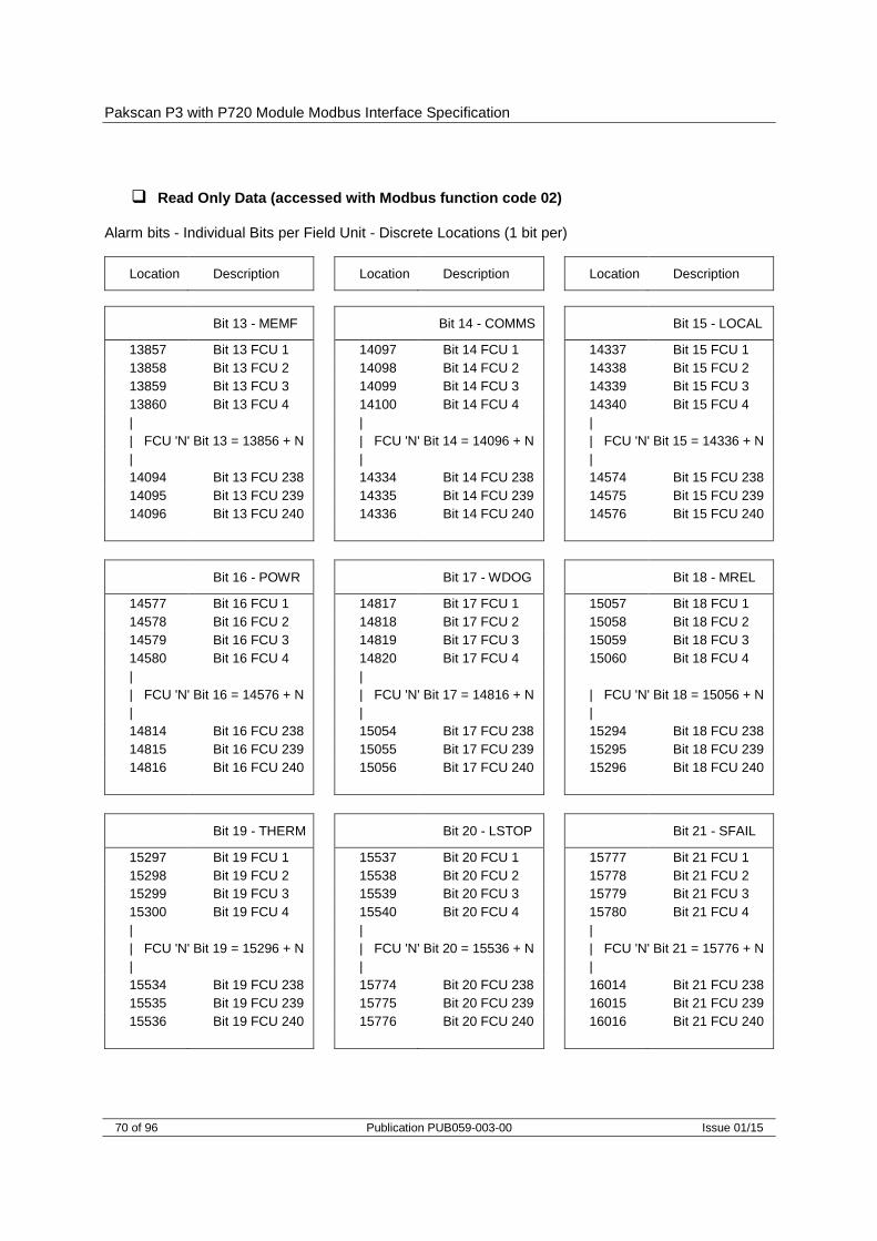
Pakscan P3 with P720 Module Modbus Interface Specification
70 of 96 Publication PUB059-003-00 Issue 01/15
Read Only Data (accessed with Modbus function code 02)
Alarm bits - Individual Bits per Field Unit - Discrete Locations (1 bit per)
Location Description Location Description Location Description
Bit 13 - MEMF Bit 14 - COMMS Bit 15 - LOCAL
13857 Bit 13 FCU 1 14097 Bit 14 FCU 1 14337 Bit 15 FCU 1
13858 Bit 13 FCU 2 14098 Bit 14 FCU 2 14338 Bit 15 FCU 2
13859 Bit 13 FCU 3 14099 Bit 14 FCU 3 14339 Bit 15 FCU 3
13860 Bit 13 FCU 4 14100 Bit 14 FCU 4 14340 Bit 15 FCU 4
| | |
| FCU 'N' Bit 13 = 13856 + N | FCU 'N' Bit 14 = 14096 + N | FCU 'N' Bit 15 = 14336 + N
| | |
14094 Bit 13 FCU 238 14334 Bit 14 FCU 238 14574 Bit 15 FCU 238
14095 Bit 13 FCU 239 14335 Bit 14 FCU 239 14575 Bit 15 FCU 239
14096 Bit 13 FCU 240 14336 Bit 14 FCU 240 14576 Bit 15 FCU 240
Bit 16 - POWR Bit 17 - WDOG Bit 18 - MREL
14577 Bit 16 FCU 1 14817 Bit 17 FCU 1 15057 Bit 18 FCU 1
14578 Bit 16 FCU 2 14818 Bit 17 FCU 2 15058 Bit 18 FCU 2
14579 Bit 16 FCU 3 14819 Bit 17 FCU 3 15059 Bit 18 FCU 3
14580 Bit 16 FCU 4 14820 Bit 17 FCU 4 15060 Bit 18 FCU 4
| |
| FCU 'N' Bit 16 = 14576 + N | FCU 'N' Bit 17 = 14816 + N | FCU 'N' Bit 18 = 15056 + N
| | |
14814 Bit 16 FCU 238 15054 Bit 17 FCU 238 15294 Bit 18 FCU 238
14815 Bit 16 FCU 239 15055 Bit 17 FCU 239 15295 Bit 18 FCU 239
14816 Bit 16 FCU 240 15056 Bit 17 FCU 240 15296 Bit 18 FCU 240
Bit 19 - THERM Bit 20 - LSTOP Bit 21 - SFAIL
15297 Bit 19 FCU 1 15537 Bit 20 FCU 1 15777 Bit 21 FCU 1
15298 Bit 19 FCU 2 15538 Bit 20 FCU 2 15778 Bit 21 FCU 2
15299 Bit 19 FCU 3 15539 Bit 20 FCU 3 15779 Bit 21 FCU 3
15300 Bit 19 FCU 4 15540 Bit 20 FCU 4 15780 Bit 21 FCU 4
| | |
| FCU 'N' Bit 19 = 15296 + N | FCU 'N' Bit 20 = 15536 + N | FCU 'N' Bit 21 = 15776 + N
| | |
15534 Bit 19 FCU 238 15774 Bit 20 FCU 238 16014 Bit 21 FCU 238
15535 Bit 19 FCU 239 15775 Bit 20 FCU 239 16015 Bit 21 FCU 239
15536 Bit 19 FCU 240 15776 Bit 20 FCU 240 16016 Bit 21 FCU 240

Yokogawa and Honeywell SI Protocols
Issue 01/15 Publication PUB059-003-00 71 of 96
Bit 22 - VOBS Bit 23 - VJAM Bit 24 - AUXOR
16017 Bit 22 FCU 1 16257 Bit 23 FCU 1 16497 Bit 24 FCU 1
16018 Bit 22 FCU 2 16258 Bit 23 FCU 2 16498 Bit 24 FCU 2
16019 Bit 22 FCU 3 16259 Bit 23 FCU 3 16499 Bit 24 FCU 3
16020 Bit 22 FCU 4 16260 Bit 23 FCU 4 16500 Bit 24 FCU 4
| | |
| FCU 'N' Bit 22 = 16016 + N | FCU 'N' Bit 23 = 16256 + N | FCU 'N' Bit 24 = 16496 + N
| | |
16254 Bit 22 FCU 238 16494 Bit 23 FCU 238 16734 Bit 24 FCU 238
16255 Bit 22 FCU 239 16495 Bit 23 FCU 239 16735 Bit 24 FCU 239
16256 Bit 22 FCU 240 16496 Bit 23 FCU 240 16736 Bit 24 FCU 240
Bit 25 - VTT Bit 26 - R Bit 27 - MMOVE
16737 Bit 25 FCU 1 16977 Bit 26 FCU 1 17217 Bit 27 FCU 1
16738 Bit 25 FCU 2 16978 Bit 26 FCU 2 17218 Bit 27 FCU 2
16739 Bit 25 FCU 3 16979 Bit 26 FCU 3 17219 Bit 27 FCU 3
16740 Bit 25 FCU 4 16980 Bit 26 FCU 4 17220 Bit 27 FCU 4
| | |
| FCU 'N' Bit 25 = 16736 + N | FCU 'N' Bit 26 = 16976 + N | FCU 'N' Bit 27 = 17216 + N
| | |
16974 Bit 25 FCU 238 17214 Bit 26 FCU 238 17454 Bit 27 FCU 238
16975 Bit 25 FCU 239 17215 Bit 26 FCU 239 17455 Bit 27 FCU 239
16976 Bit 25 FCU 240 17216 Bit 26 FCU 240 17456 Bit 27 FCU 240
Bit 28 - EOT
17457 Bit 28 FCU 1
17458 Bit 28 FCU 2
17459 Bit 28 FCU 3
17460 Bit 28 FCU 4
|
| FCU 'N' Bit 28 = 17456 + N
|
17694 Bit 28 FCU 238
17695 Bit 28 FCU 239
17696 Bit 28 FCU 240 N = field unit address number in the range 1 to 240
Read Only Data (accessed with Modbus function code 02)
Alarm bits - Individual Bits per Field Unit - Discrete Locations (1 bit per)
Location Description Location Description Location Description

Pakscan P3 with P720 Module Modbus Interface Specification
72 of 96 Publication PUB059-003-00 Issue 01/15
Read Only Data (accessed with Modbus function code 02)
Digital Inputs (Field Units) – Relay Coil Status (Applies to General Purpose Field Units only) The following data locations contain the status of the output relays in the General Purpose field units. These may be considered as 'status signals'. The state of the coil may be examined by using Function Code 02 on a discrete by discrete basis. For writing data to relay coils see later.
Location Description Location Description Location Description
Relay 4 Coil Relay 1 Coil Relay 3 Coil
17697 Rly 4 FCU 1 17937 Rly 1 FCU 1 18177 Rly 3 FCU 1
17698 Rly 4 FCU 2 17938 Rly 1 FCU 2 18178 Rly 3 FCU 2
17699 Rly 4 FCU 3 17939 Rly 1 FCU 3 18179 Rly 3 FCU 3
17670 Rly 4 FCU 4 17940 Rly 1 FCU 4 18180 Rly 3 FCU 4
| | |
| FCU 'N' Rly 4 = 17696 + N | FCU 'N' Rly 1 = 17936 + N | FCU 'N' Rly 3 = 18176 + N
| | |
17934 Rly 4 FCU 238 18174 Rly 1 FCU 238 18414 Rly 3 FCU 238
17935 Rly 4 FCU 239 18175 Rly 1 FCU 239 18415 Rly 3 FCU 239
17936 Rly 4 FCU 240 18176 Rly 1 FCU 240 18416 Rly 3 FCU 240
Relay 2 Coil
18417 Rly 2 FCU 1
18418 Rly 2 FCU 2
18419 Rly 2 FCU 3
18420 Rly 2 FCU 4
|
| FCU 'N' Rly 2 = 18416 + N
|
18654 Rly 2 FCU 238
18655 Rly 2 FCU 239
18656 Rly 2 FCU 240
N = field unit address number in the range 1 to 240

Yokogawa and Honeywell SI Protocols
Issue 01/15 Publication PUB059-003-00 73 of 96
5.6.2 Digital Outputs (Field Units)
Write Data (accessed with Modbus function code 05 and 15)
When writing outputs to the field units, to assert the command (energise the coil) write 0xFF00 (or any data other than 0x0000). To remove the command (de-energise the coil) write 0x0000. Actuator control commands never require to be turned off, so there is no need to write a de-energise command. Commands - Adjacent coils per Field Unit - Coil locations (1 bit per)
Location Description Location Description
00033 Rly 1 FCU 1 (Close Cmd) 00034 Rly 2 FCU 1 (Open Cmd)
00035 Rly 1 FCU 2 (Close Cmd) 00036 Rly 2 FCU 2 (Open Cmd)
00037 Rly 1 FCU 3 (Close Cmd) 00038 Rly 2 FCU 3 (Open Cmd)
00039 Rly 1 FCU 4 (Close Cmd) 00040 Rly 2 FCU 4 (Open Cmd)
00041 Rly 1 FCU 5 (Close Cmd) 00042 Rly 2 FCU 5 (Open Cmd)
00043 Rly 1 FCU 6 (Close Cmd) 00044 Rly 2 FCU 6 (Open Cmd)
00045 Rly 1 FCU 7 (Close Cmd) 00046 Rly 2 FCU 7 (Open Cmd)
00047 Rly 1 FCU 8 (Close Cmd) 00048 Rly 2 FCU 8 (Open Cmd)
00049 Rly 1 FCU 9 (Close Cmd) 00050 Rly 2 FCU 9 (Open Cmd)
00051 Rly 1 FCU 10 (Close Cmd) 00052 Rly 2 FCU 10 (Open Cmd)
00053 Rly 1 FCU 11 (Close Cmd) 00054 Rly 2 FCU 11 (Open Cmd)
00055 Rly 1 FCU 12 (Close Cmd) 00056 Rly 2 FCU 12 (Open Cmd)
00057 Rly 1 FCU 13 (Close Cmd) 00058 Rly 2 FCU 13 (Open Cmd)
00059 Rly 1 FCU 14 (Close Cmd) 00060 Rly 2 FCU 14 (Open Cmd)
00061 Rly 1 FCU 15 (Close Cmd) 00062 Rly 2 FCU 15 (Open Cmd)
00063 Rly 1 FCU 16 (Close Cmd) 00064 Rly 2 FCU 16 (Open Cmd)
| |
| FCU 'N' Rly 1 00032 + 2N - 1 | FCU 'N' Rly 2 = 00032 + 2N
| |
00501 Rly 1 FCU 235 (Close Cmd) 00502 Rly 2 FCU 235 (Open Cmd)
00503 Rly 1 FCU 236 (Close Cmd) 00504 Rly 2 FCU 236 (Open Cmd)
00505 Rly 1 FCU 237 (Close Cmd) 00506 Rly 2 FCU 237 (Open Cmd)
00507 Rly 1 FCU 238 (Close Cmd) 00508 Rly 2 FCU 238 (Open Cmd)
00509 Rly 1 FCU 239 (Close Cmd) 00510 Rly 2 FCU 239 (Open Cmd)
00511 Rly 1 FCU 240 (Close Cmd) 00512 Rly 2 FCU 240 (Open Cmd)
Note that the access to these coils is also mapped to alternate locations starting 00513 (Open Command) through to 01472 (ESD Command, field unit 240) N = field unit address number in the range 1 to 240
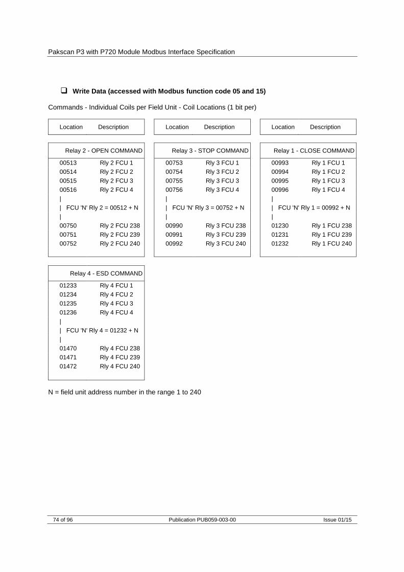
Pakscan P3 with P720 Module Modbus Interface Specification
74 of 96 Publication PUB059-003-00 Issue 01/15
Write Data (accessed with Modbus function code 05 and 15)
Commands - Individual Coils per Field Unit - Coil Locations (1 bit per)
Location Description Location Description Location Description
Relay 2 - OPEN COMMAND Relay 3 - STOP COMMAND Relay 1 - CLOSE COMMAND
00513 Rly 2 FCU 1 00753 Rly 3 FCU 1 00993 Rly 1 FCU 1
00514 Rly 2 FCU 2 00754 Rly 3 FCU 2 00994 Rly 1 FCU 2
00515 Rly 2 FCU 3 00755 Rly 3 FCU 3 00995 Rly 1 FCU 3
00516 Rly 2 FCU 4 00756 Rly 3 FCU 4 00996 Rly 1 FCU 4
| | |
| FCU 'N' Rly 2 = 00512 + N | FCU 'N' Rly 3 = 00752 + N | FCU 'N' Rly 1 = 00992 + N
| | |
00750 Rly 2 FCU 238 00990 Rly 3 FCU 238 01230 Rly 1 FCU 238
00751 Rly 2 FCU 239 00991 Rly 3 FCU 239 01231 Rly 1 FCU 239
00752 Rly 2 FCU 240 00992 Rly 3 FCU 240 01232 Rly 1 FCU 240
Relay 4 - ESD COMMAND
01233 Rly 4 FCU 1
01234 Rly 4 FCU 2
01235 Rly 4 FCU 3
01236 Rly 4 FCU 4
|
| FCU 'N' Rly 4 = 01232 + N
|
01470 Rly 4 FCU 238
01471 Rly 4 FCU 239
01472 Rly 4 FCU 240
N = field unit address number in the range 1 to 240
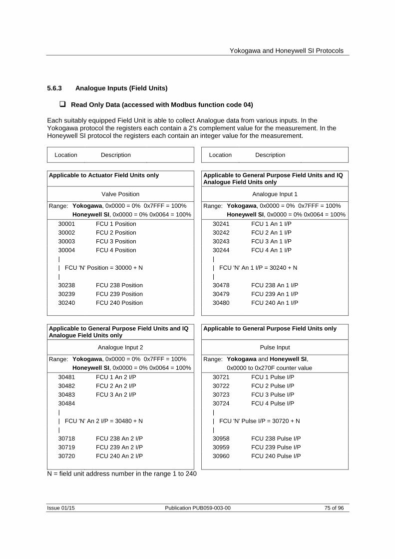
Yokogawa and Honeywell SI Protocols
Issue 01/15 Publication PUB059-003-00 75 of 96
5.6.3 Analogue Inputs (Field Units)
Read Only Data (accessed with Modbus function code 04)
Each suitably equipped Field Unit is able to collect Analogue data from various inputs. In the Yokogawa protocol the registers each contain a 2's complement value for the measurement. In the Honeywell SI protocol the registers each contain an integer value for the measurement.
Location Description Location Description
Applicable to Actuator Field Units only Applicable to General Purpose Field Units and IQ Analogue Field Units only
Valve Position
Analogue Input 1
Range: Yokogawa, 0x0000 = 0% 0x7FFF = 100% Range: Yokogawa, 0x0000 = 0% 0x7FFF = 100%
Honeywell SI, 0x0000 = 0% 0x0064 = 100% Honeywell SI, 0x0000 = 0% 0x0064 = 100%
30001 FCU 1 Position 30241 FCU 1 An 1 I/P
30002 FCU 2 Position 30242 FCU 2 An 1 I/P
30003 FCU 3 Position 30243 FCU 3 An 1 I/P
30004 FCU 4 Position 30244 FCU 4 An 1 I/P
| |
| FCU 'N' Position = 30000 + N | FCU 'N' An 1 I/P = 30240 + N
| |
30238 FCU 238 Position 30478 FCU 238 An 1 I/P
30239 FCU 239 Position 30479 FCU 239 An 1 I/P
30240 FCU 240 Position 30480 FCU 240 An 1 I/P
Applicable to General Purpose Field Units and IQ Analogue Field Units only
Applicable to General Purpose Field Units only
Analogue Input 2
Pulse Input
Range: Yokogawa, 0x0000 = 0% 0x7FFF = 100% Range: Yokogawa and Honeywell SI,
Honeywell SI, 0x0000 = 0% 0x0064 = 100% 0x0000 to 0x270F counter value
30481 FCU 1 An 2 I/P 30721 FCU 1 Pulse I/P
30482 FCU 2 An 2 I/P 30722 FCU 2 Pulse I/P
30483 FCU 3 An 2 I/P 30723 FCU 3 Pulse I/P
30484 30724 FCU 4 Pulse I/P
| |
| FCU 'N' An 2 I/P = 30480 + N | FCU 'N' Pulse I/P = 30720 + N
| |
30718 FCU 238 An 2 I/P 30958 FCU 238 Pulse I/P
30719 FCU 239 An 2 I/P 30959 FCU 239 Pulse I/P
30720 FCU 240 An 2 I/P 30960 FCU 240 Pulse I/P
N = field unit address number in the range 1 to 240

Pakscan P3 with P720 Module Modbus Interface Specification
76 of 96 Publication PUB059-003-00 Issue 01/15
Read Only Data (accessed with Modbus function code 04)
IQ Range, CVA and EH / SI Actuator Field Units are able to collect both Current and Historical Torque (pressure for EH / SI) data from the actuator. The following 16 bit register locations each contain a value relating to the actuator torque.
Location Description
Current Torque
Range: Yokogawa, 0x0000 = 0% 0x7FFF = 120%
Honeywell SI, 0x0000 = 0% 0x0078 = 120%
30961 FCU 1 Current Torque
30962 FCU 2 Current Torque
30963 FCU 3 Current Torque
30964 FCU 4 Current Torque
|
| FCU 'N' Position = 30960 + N
|
31198 FCU 238 Current Torque
31199 FCU 239 Current Torque
31200 FCU 240 Current Torque
Location Description Location Description
Historical Torque Profile
Range: Yokogawa, 0x0000 = 0% 0x7FFF = 120%
Honeywell SI, 0x0000 = 0% 0x0078 = 120%
The Torque value is related to the readings taken across the valve stroke, Position 0 and 100% are not used as these may be set to full torque for a torque seating valve. Torque readings are available for 6%, 19%, 31%, 44%, 56%, 69%, 81%, and 94% positions. The data is stacked in pairs where an open torque is followed by a close torque for each position, for each field unit.
The data is historical and only updated on completion of a full stroke of the valve from open to close, or from close to open. Further the data is not reported from the actuator to the master station unless the Torque Data Filter Factor is set to 0 (refer to the Field Unit manual for more information).
31201 6% Open Torque FCU 1 31202 6% Close Torque FCU 1
31203 6% Open Torque FCU 2 31204 6% Close Torque FCU 2
31205 6% Open Torque FCU 3 31206 6% Close Torque FCU 3
| |
| FCU ’N’ 6% Open Torque = 31200 + 2N -1 | FCU ‘N’ 6% Close Torque = 31200 + 2N
| |
31679 6% Open Torque FCU 240 31680 6% Close Torque FCU 240
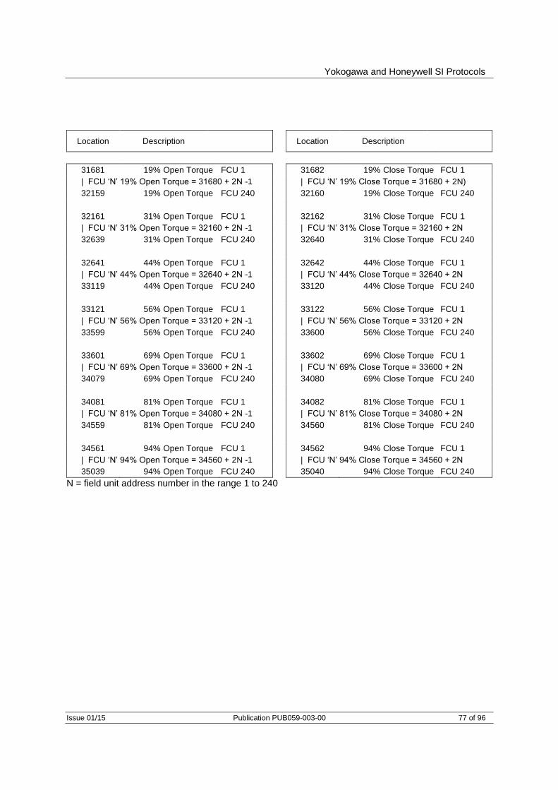
Yokogawa and Honeywell SI Protocols
Issue 01/15 Publication PUB059-003-00 77 of 96
Location Description Location Description
31681 19% Open Torque FCU 1 31682 19% Close Torque FCU 1
| FCU ‘N’ 19% Open Torque = 31680 + 2N -1 | FCU ‘N’ 19% Close Torque = 31680 + 2N)
32159 19% Open Torque FCU 240 32160 19% Close Torque FCU 240
32161 31% Open Torque FCU 1 32162 31% Close Torque FCU 1
| FCU ‘N’ 31% Open Torque = 32160 + 2N -1 | FCU ‘N’ 31% Close Torque = 32160 + 2N
32639 31% Open Torque FCU 240 32640 31% Close Torque FCU 240
32641 44% Open Torque FCU 1 32642 44% Close Torque FCU 1
| FCU ‘N’ 44% Open Torque = 32640 + 2N -1 | FCU ‘N’ 44% Close Torque = 32640 + 2N
33119 44% Open Torque FCU 240 33120 44% Close Torque FCU 240
33121 56% Open Torque FCU 1 33122 56% Close Torque FCU 1
| FCU ‘N’ 56% Open Torque = 33120 + 2N -1 | FCU ‘N’ 56% Close Torque = 33120 + 2N
33599 56% Open Torque FCU 240 33600 56% Close Torque FCU 240
33601 69% Open Torque FCU 1 33602 69% Close Torque FCU 1
| FCU ‘N’ 69% Open Torque = 33600 + 2N -1 | FCU ‘N’ 69% Close Torque = 33600 + 2N
34079 69% Open Torque FCU 240 34080 69% Close Torque FCU 240
34081 81% Open Torque FCU 1 34082 81% Close Torque FCU 1
| FCU ‘N’ 81% Open Torque = 34080 + 2N -1 | FCU ‘N’ 81% Close Torque = 34080 + 2N
34559 81% Open Torque FCU 240 34560 81% Close Torque FCU 240
34561 94% Open Torque FCU 1 34562 94% Close Torque FCU 1
| FCU ‘N’ 94% Open Torque = 34560 + 2N -1 | FCU ‘N’ 94% Close Torque = 34560 + 2N
35039 94% Open Torque FCU 240 35040 94% Close Torque FCU 240
N = field unit address number in the range 1 to 240

Pakscan P3 with P720 Module Modbus Interface Specification
78 of 96 Publication PUB059-003-00 Issue 01/15
5.6.4 Analogue Outputs (Field Units)
Write Data (accessed with Modbus function codes 03, 06, 16)
General Purpose Field Units are able to accept an 'Analogue Output' signal for connection to a controller or positioner. The following 16 bit register locations may be written to with a 2's complement value (Yokogawa protocol), or signed integer value (Honeywell SI protocol) relating to the setting of this output.
Location Description
Applicable to General Purpose Field Units only
Analogue Output
Range: Yokogawa, 0x0000 = 0% 0x7FFF = 100%
Honeywell SI, 0x0000 = 0% 0x0064 = 100%
40241 FCU 1 Analogue output
40242 FCU 2 Analogue output
40243 FCU 3 Analogue output
40244 FCU 4 Analogue output
|
| FCU 'N' Position = 40240 + N
|
40478 FCU 238 Analogue output
40479 FCU 239 Analogue output
40480 FCU 240 Analogue output
Location Description
Applicable to Actuator Field Units only
Valve Position Control
Range: Yokogawa, 0x0000 = 0% 0x7FFF = 100%
Honeywell SI, 0x0000 = 0% 0x0064 = 100%
40001 FCU 1 Position control
40002 FCU 2 Position control
40003 FCU 3 Position control
40004 FCU 4 Position control
|
| FCU 'N' Position = 40000 + N
|
40238 FCU 238 Position control
40239 FCU 239 Position control
40240 FCU 240 Position control
Particular Actuator Field Units are able to accept a Desired Position signal. The following 16 bit register locations may be written to with a 2's complement value (Yokogawa protocol), or signed integer value (Honeywell SI protocol) relating to the desired valve position.

Is
sue 0
1/1
5
Public
atio
n P
UB
059
-003-0
0
79 o
f 96
Yokog
aw
a a
nd
Hon
eyw
ell S
I Pro
toco
ls
5.7 Field unit inputs and outputs available
5.7.1 Digital Inputs
FCU Type
Data Bit or Register IQ Range Actuator
A, AQ, Q, ROMpak
GPFCU (GP) GPFCU (ACT) CVA EH / SI
Pro
CMA IQ Analogue
Bit 0 AUX 1 R DIN 1 R R AUX 1 R R
Bit 1 AUX 2 R DIN 2 R BAKPWR AUX 2 R R
Bit 2 OAS OAS DIN 3 OAS OAS OAS OAS R
Bit 3 CAS CAS DIN 4 CAS CAS CAS CAS R
Bit 4 STOP STOP DIN 5 STOP STOP STOP R R
Bit 5 MOVE MRUN DIN 6 MRUN MOVE Travelling MOVE R
Bit 6 MRO MRO DIN 7 MRO TRO MRO R R
Bit 7 MRC MRC DIN 8 MRC TRC MRC R R
Bit 8 AUX 3 EXT R EXT R AUX 3 R R
Bit 9 AUX 4 R R R R AUX 4 R R
Bit 10 LBON LBON LBON LBON LBON LBON LBON LBON
Bit 11 NALRM NALRM NALRM NALRM NALRM NALRM NALRM NALRM
Bit 12 ALRM ALRM ALRM ALRM ALRM ALRM ALRM ALRM
Bit 13 MEMF MEMF MEMF MEMF MEMF MEMF R MEMF
Bit 14 COMMS COMMS COMMS COMMS COMMS COMMS COMMS COMMS
Bit 15 LOCAL CNA R CNA LOCAL LOCAL LOCAL R
Bit 16 POWR POWR POWR POWR POWR POWR POWR POWR
Bit 17 WDOG WDOG WDOG WDOG WDOG WDOG WDOG WDOG
Bit 18 MREL MREL R MREL MREL MREL MREL R
Bit 19 THERM THERM R THERM THERM FAULT R R
Bit 20 LSTOP LSTOP R LSTOP LSTOP LSTOP LSTOP R
Bit 21 SFAIL SFAIL R SFAIL SFAIL SFAIL SFAIL R
Bit 22 VOBS VOBS R VOBS VOBS VOBS VOBS R
Bit 23 VJAM VJAM R VJAM VJAM VJAM R R
Bit 24 AUXOR MOP R MOP R AUXOR R R
Bit 25 VTT MCL R MCL R VTT R R
Bit 26 R MOPG R MOPG R R R R
Bit 27 MMOVE MCLG R MCLG MMOVE MMOVE R R
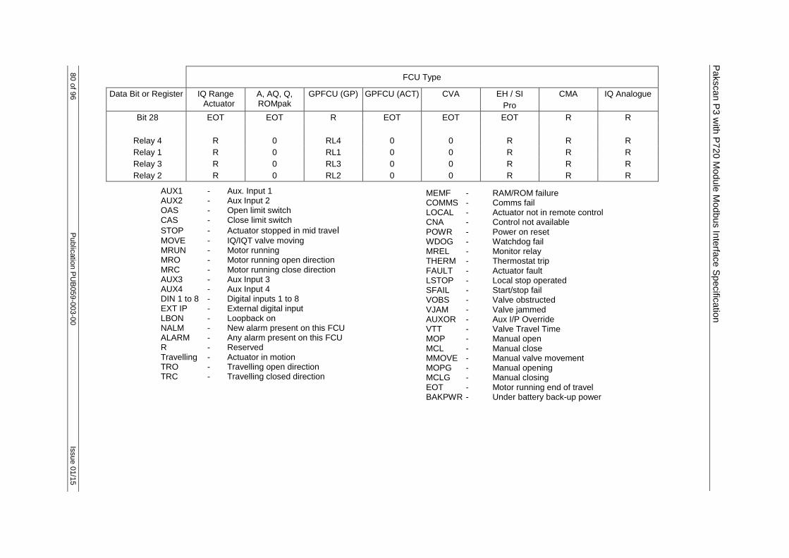
Pakscan P
3 w
ith P
720 M
od
ule
Mod
bus In
terfa
ce S
pecific
atio
n
80 o
f 96
Public
atio
n P
UB
059
-003-0
0
Issue 0
1/1
5
FCU Type
Data Bit or Register IQ Range Actuator
A, AQ, Q, ROMpak
GPFCU (GP) GPFCU (ACT) CVA EH / SI
Pro
CMA IQ Analogue
Bit 28 EOT EOT R EOT EOT EOT R R
Relay 4 R 0 RL4 0 0 R R R
Relay 1 R 0 RL1 0 0 R R R
Relay 3 R 0 RL3 0 0 R R R
Relay 2 R 0 RL2 0 0 R R R
AUX1 - Aux. Input 1 AUX2 - Aux Input 2 OAS - Open limit switch CAS - Close limit switch
STOP - Actuator stopped in mid travel MOVE - IQ/IQT valve moving MRUN - Motor running MRO - Motor running open direction MRC - Motor running close direction AUX3 - Aux Input 3 AUX4 - Aux Input 4 DIN 1 to 8 - Digital inputs 1 to 8 EXT IP - External digital input LBON - Loopback on NALM - New alarm present on this FCU ALARM - Any alarm present on this FCU R - Reserved Travelling - Actuator in motion TRO - Travelling open direction TRC - Travelling closed direction
MEMF - RAM/ROM failure COMMS - Comms fail LOCAL - Actuator not in remote control CNA - Control not available POWR - Power on reset WDOG - Watchdog fail MREL - Monitor relay THERM - Thermostat trip FAULT - Actuator fault LSTOP - Local stop operated SFAIL - Start/stop fail VOBS - Valve obstructed VJAM - Valve jammed AUXOR - Aux I/P Override VTT - Valve Travel Time MOP - Manual open MCL - Manual close MMOVE - Manual valve movement MOPG - Manual opening MCLG - Manual closing EOT - Motor running end of travel BAKPWR - Under battery back-up power

Is
sue 0
1/1
5
Public
atio
n P
UB
059
-003-0
0
81 o
f 96
Yokog
aw
a a
nd
Hon
eyw
ell S
I Pro
toco
ls
5.7.2 Digital Outputs
FCU Type
Data Bit or Register IQ Range Actuator
A, AQ, Q, ROMpak
GPFCU (GP) GPFCU (ACT) CVA EH / SI
Pro
CMA IQ Analogue
Open (Relay 2) Y Y Y Y Y Y Y N
Stop (Relay 3) Y Y Y Y Y Y Y N
Close (Relay 1) Y Y Y Y Y Y Y N
ESD (Relay 4) Y Y Y Y Y Y Y N
5.7.3 Analogue Inputs
FCU Type
Data Bit or Register IQ Range Actuator
A, AQ, Q, ROMpak
GPFCU (GP) GPFCU (ACT) CVA EH / SI
Pro
CMA IQ Analogue
Valve Position Y Y N Y Y Y Y N
Current Torque Y N N N Y Y (pressure) N N
Historical Torque Y N N N Y Y N N
Analogue Input 1 N N Y N N N N Y
Analogue Input 2 N N Y N N N N Y
Pulse Input N N Y N N N N N
5.7.4 Analogue Outputs
FCU Type
Data Bit or Register IQ Range Actuator
A, AQ, Q, ROMpak
GPFCU (GP) GPFCU (ACT) CVA EH / SI
Pro
CMA IQ Analogue
Position Control Y Y N Y Y Y Y N
Analogue Output N N Y N N N N N
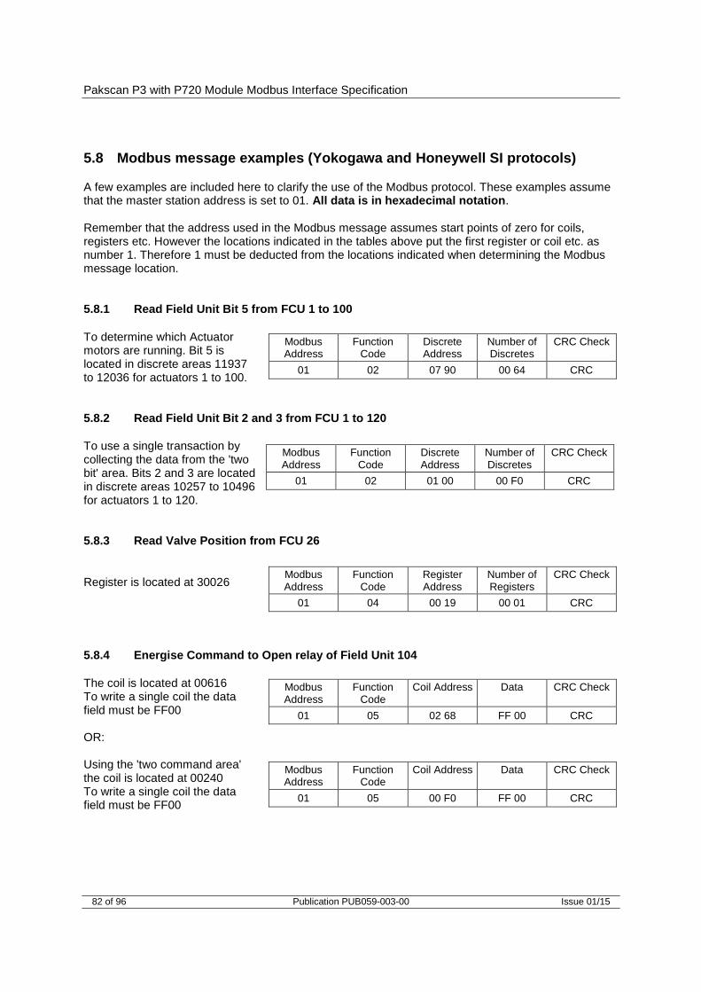
Pakscan P3 with P720 Module Modbus Interface Specification
82 of 96 Publication PUB059-003-00 Issue 01/15
5.8 Modbus message examples (Yokogawa and Honeywell SI protocols)
A few examples are included here to clarify the use of the Modbus protocol. These examples assume that the master station address is set to 01. All data is in hexadecimal notation. Remember that the address used in the Modbus message assumes start points of zero for coils, registers etc. However the locations indicated in the tables above put the first register or coil etc. as number 1. Therefore 1 must be deducted from the locations indicated when determining the Modbus message location. 5.8.1 Read Field Unit Bit 5 from FCU 1 to 100
To determine which Actuator motors are running. Bit 5 is located in discrete areas 11937 to 12036 for actuators 1 to 100. 5.8.2 Read Field Unit Bit 2 and 3 from FCU 1 to 120
To use a single transaction by collecting the data from the 'two bit' area. Bits 2 and 3 are located in discrete areas 10257 to 10496 for actuators 1 to 120. 5.8.3 Read Valve Position from FCU 26
Register is located at 30026 5.8.4 Energise Command to Open relay of Field Unit 104
The coil is located at 00616 To write a single coil the data field must be FF00 OR: Using the 'two command area' the coil is located at 00240 To write a single coil the data field must be FF00
Modbus Address
Function Code
Discrete Address
Number of Discretes
CRC Check
01 02 07 90 00 64 CRC
Modbus Address
Function Code
Discrete Address
Number of Discretes
CRC Check
01 02 01 00 00 F0 CRC
Modbus Address
Function Code
Register Address
Number of Registers
CRC Check
01 04 00 19 00 01 CRC
Modbus Address
Function Code
Coil Address Data CRC Check
01 05 02 68 FF 00 CRC
Modbus Address
Function Code
Coil Address Data CRC Check
01 05 00 F0 FF 00 CRC

Yokogawa and Honeywell SI Protocols
Issue 01/15 Publication PUB059-003-00 83 of 96
5.8.5 Write Desired Valve Position for FCU 26 to be 50%
Register is located at 40026. With Yokogawa protocol, 50% is 3FFF and with Honeywell SI protocol, 50% is 0032 Using Yokogawa protocol Using Honeywell SI protocol
Modbus Address
Function Code
Register Addess
Data CRC Check
01 06 00 19 3F FF CRC
Modbus Address
Function Code
Register Addess
Data CRC Check
01 06 00 19 00 32 CRC

Pakscan P3 with P720 Module Modbus Interface Specification
84 of 96 Publication PUB059-003-00 Issue 01/15
(This page is intentionally blank)

Field Unit Block and Parameter Allocations
Issue 01/15 Publication PUB059-003-00 85 of 96
6 FIELD UNIT BLOCK AND PARAMETER ALLOCATIONS
The Pakscan current loop system comprises a number of Field Control Units connected to a Master Station via a 2-wire loop. The Master Station manages the loop, collects data from, and issues instructions to, the Field Units. Data within the Pakscan system is organised in Blocks and Parameters relating to specific functions or activities within the Field Control Units (e.g. Digital inputs, Alarms, Position control). Each FCU supports up to 32 blocks with each block containing eight 16-bit parameters. This section details the use of these blocks and parameters in the transfer of data between the Field Unit and Master Station. A subset of this data is then used in host computer communications when using Modbus. The field unit blocks and parameters can be examined on a Pakscan 3 master station on specific field unit screens (HMI or web). The various types of Field Unit have different block and parameter allocations. The following sections give details of all the allocations applicable to each actuator and field unit type.
6.1 Block and parameter construction
The FCU acts as a slave to the master station, responding only when interrogated, just as the master station acts as a slave to the host computer system. The data base in the field unit comprises a series of records organised into Blocks and Parameters. Each Parameter contains 16 data bits. There are 32 Blocks, each of 8 Parameters, allocated for every field unit on the system, though not all these Blocks contain relevant data. 6.1.1 Digital inputs
Each field unit has direct digital inputs from the connected actuator or other device. The status of these digital signals is reported in the Digital Input Block (Block 2 Parameter 0). The block also contains indication of any alarms present in the Alarm block. 6.1.2 Alarm block
The Alarm Block holds data about alarms either directly connected to the field unit, or logically derived from the status of all the inputs. Transient alarm data bits are individually latched by the master station and automatically cleared from the field unit on successful transfer. Alarm conditions will not return to normal until both the source of the alarm is corrected and the alarm is both 'read' and 'accepted' by the master station. 6.1.3 Analogue and counter input data
The field unit will report analogue or counter values to the master station only when the measurement changes by an amount that exceeds the 'Deviation' setting by 1 digit, or the 'Update Timeout' period has expired. These parameters are adjustable, and included in the system to ensure that analogue reporting only occurs when necessary. The host computer has access to the last reported analogue value in the master station.

Pakscan P3 with P720 Module Modbus Interface Specification
86 of 96 Publication PUB059-003-00 Issue 01/15
6.1.4 Outputs
The master station transfers both digital and analogue outputs from the host computer directly to the connected field unit. There are no registers holding output data present within the master station itself.
6.2 Block and parameter usage
The following lists show all the relevant Blocks and Parameters that may exist in FCU's. They also show the meaning of parameters for each Field Unit type and which parameters are supported by the particular Field Unit types. All parameters are 16 bit quantities although most have a limited range of values. The Parameters are transmitted Most Significant Data Byte first. Field Unit Types Available: CP - Used for IQ3, CVA, CMA, ROMpak actuators IQmk1 - Used for IQ1, IQ2 and IQT actuators INTEGRAL - A, AQ and Q Actuator control integral to the actuator GPFCU (GP) - General Purpose version of GPFCU GPFCU (Act) - Actuator Control version of GPFCU IQ Analogue - Additional analogue input card for IQT actuators already fitted with FCU EH / SI - Electro-hydraulic actuator version of IQT field unit Key to Symbols Used: RO - Read Only R/W - Read / Write WO - Write Only Y - Item supported for this type of Field Unit R - Reserved for internal or future use BLANK - A Blank entry indicates that the item is not supported for that Field
Unit type. Reads of that item generally return zero. M - Data indicated is as read with a Paktester, if it is read via a master
station screen using Block and Parameter reads the data will be invalid.
Notes:
a) Great care must be exercised in the writing of data to a field unit. In general this can only be achieved if the field unit is in ‘loopback’. b) The range display will differ when viewed with a master station block and parameter read compared to a Paktester read. In general, the master station re-ranges the range to show 32767 as the 100% value as a decimal whilst the Paktester will show 100% as 0xFFFF in hexadecimal. Writes from the master station should use the master station range. c) The ranges indicated in the tables are those seen with a Paktester directly connected to the field unit.
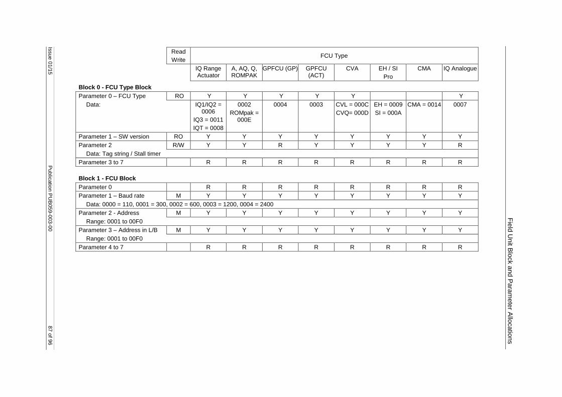
Issue 0
1/1
5
Public
atio
n P
UB
059
-003-0
0
87 o
f 96
Read
Write FCU Type
IQ Range Actuator
A, AQ, Q, ROMPAK
GPFCU (GP) GPFCU (ACT)
CVA EH / SI
Pro
CMA IQ Analogue
Fie
ld U
nit B
lock a
nd P
ara
mete
r Allo
catio
ns
Block 0 - FCU Type Block
Parameter 0 – FCU Type RO Y Y Y Y Y Y
Data: IQ1/IQ2 = 0006
IQ3 = 0011
IQT = 0008
0002
ROMpak = 000E
0004 0003 CVL = 000C
CVQ= 000D
EH = 0009
SI = 000A
CMA = 0014 0007
Parameter 1 – SW version RO Y Y Y Y Y Y Y Y
Parameter 2 R/W Y Y R Y Y Y Y R
Data: Tag string / Stall timer
Parameter 3 to 7 R R R R R R R R
Block 1 - FCU Block
Parameter 0 R R R R R R R R
Parameter 1 – Baud rate M Y Y Y Y Y Y Y Y
Data: 0000 = 110, 0001 = 300, 0002 = 600, 0003 = 1200, 0004 = 2400
Parameter 2 - Address M Y Y Y Y Y Y Y Y
Range: 0001 to 00F0
Parameter 3 – Address in L/B M Y Y Y Y Y Y Y Y
Range: 0001 to 00F0
Parameter 4 to 7 R R R R R R R R
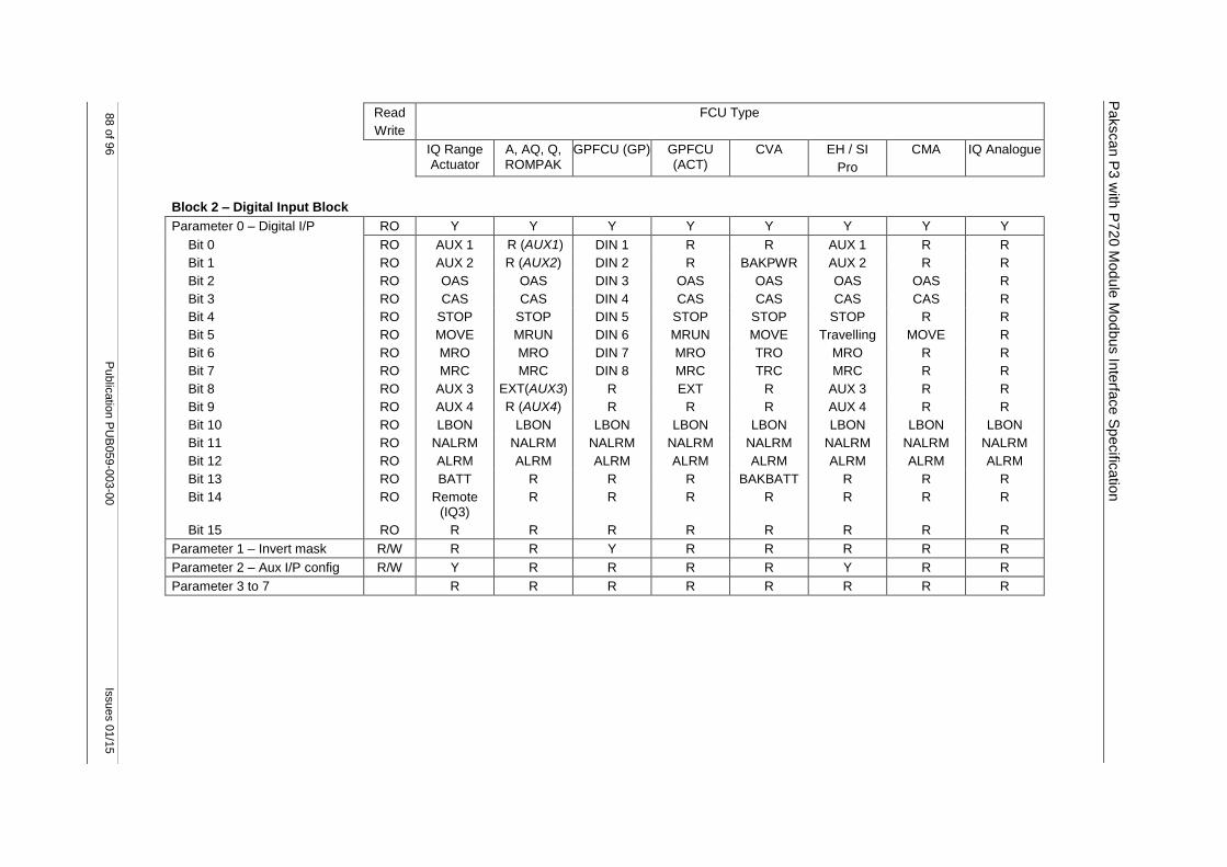
88 o
f 96
Public
atio
n P
UB
059
-003-0
0
Issues 0
1/1
5
Pakscan P
3 w
ith P
720 M
od
ule
Mod
bus In
terfa
ce S
pecific
atio
n
Read
Write
FCU Type
IQ Range Actuator
A, AQ, Q, ROMPAK
GPFCU (GP) GPFCU (ACT)
CVA EH / SI
Pro
CMA IQ Analogue
Block 2 – Digital Input Block
Parameter 0 – Digital I/P RO Y Y Y Y Y Y Y Y
Bit 0 RO AUX 1 R (AUX1) DIN 1 R R AUX 1 R R
Bit 1 RO AUX 2 R (AUX2) DIN 2 R BAKPWR AUX 2 R R
Bit 2 RO OAS OAS DIN 3 OAS OAS OAS OAS R
Bit 3 RO CAS CAS DIN 4 CAS CAS CAS CAS R
Bit 4 RO STOP STOP DIN 5 STOP STOP STOP R R
Bit 5 RO MOVE MRUN DIN 6 MRUN MOVE Travelling MOVE R
Bit 6 RO MRO MRO DIN 7 MRO TRO MRO R R
Bit 7 RO MRC MRC DIN 8 MRC TRC MRC R R
Bit 8 RO AUX 3 EXT(AUX3) R EXT R AUX 3 R R
Bit 9 RO AUX 4 R (AUX4) R R R AUX 4 R R
Bit 10 RO LBON LBON LBON LBON LBON LBON LBON LBON
Bit 11 RO NALRM NALRM NALRM NALRM NALRM NALRM NALRM NALRM
Bit 12 RO ALRM ALRM ALRM ALRM ALRM ALRM ALRM ALRM
Bit 13 RO BATT R R R BAKBATT R R R
Bit 14 RO Remote (IQ3)
R R R R R R R
Bit 15 RO R R R R R R R R
Parameter 1 – Invert mask R/W R R Y R R R R R
Parameter 2 – Aux I/P config R/W Y R R R R Y R R
Parameter 3 to 7 R R R R R R R R

Issue 0
1/1
5
Public
atio
n P
UB
059
-003-0
0
89 o
f 96
Fie
ld U
nit B
lock a
nd P
ara
mete
r Allo
catio
ns
Read
Write
FCU Type
IQ Range Actuator
A, AQ, Q, ROMPAK
GPFCU (GP) GPFCU (ACT)
CVA EH / SI
Pro
CMA IQ Analogue
Block 3 – Alarm Block
Parameter 0 – Alarms RO Y Y Y Y Y Y Y Y
Bit 0 RO MEMF MEMF MEMF MEMF MEMF MEMF R MEMF
Bit 1 RO COMMS COMMS COMMS COMMS COMMS COMMS COMMS COMMS
Bit 2 RO LOCAL CNA R CNA LOCAL LOCAL LOCAL LOCAL
Bit 3 RO POWR POWR POWR POWR POWR POWR POWR POWR
Bit 4 RO WDOG WDOG WDOG WDOG WDOG WDOG WDOG WDOG
Bit 5 RO MREL MREL R MREL MREL MREL MREL R
Bit 6 RO THERM THERM R THERM THERM FAULT R R
Bit 7 RO LSTOP LSTOP R LSTOP LSTOP LSTOP LSTOP R
Bit 8 RO SFAIL SFAIL R SFAIL SFAIL SFAIL SFAIL R
Bit 9 RO VOBS VOBS R VOBS VOBS VOBS VOBS R
Bit 10 RO VJAM VJAM R VJAM VJAM VJAM R R
Bit 11 RO AUXOR MOP R MOP R AUXOR R R
Bit 12 RO VTT MCL R MCL R VTT R R
Bit 13 RO R MOPG R MOPG R R R R
Bit 14 RO MMOVE MCLG R MCLG MMOVE MMOVE R R
Bit 15 RO EOT EOT R EOT R EOT R R
Parameter 1 – Alarm Accept R R R R R R R R
Para’ 2 – Valve Travel Time R/W Y R R R R Y R R
Parameter 3 to 7 R R R R R R R R
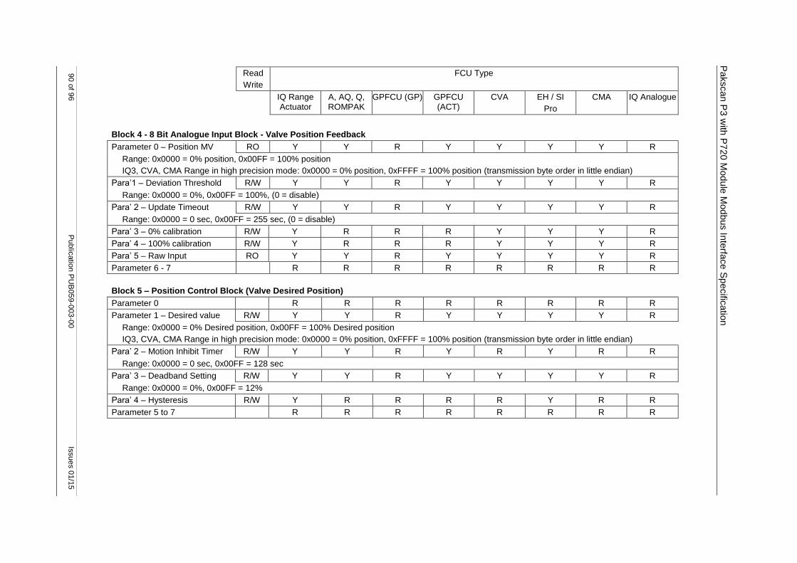
90 o
f 96
Public
atio
n P
UB
059
-003-0
0
Issues 0
1/1
5
Pakscan P
3 w
ith P
720 M
od
ule
Mod
bus In
terfa
ce S
pecific
atio
n
Read
Write
FCU Type
IQ Range Actuator
A, AQ, Q, ROMPAK
GPFCU (GP) GPFCU (ACT)
CVA EH / SI
Pro
CMA IQ Analogue
Block 4 - 8 Bit Analogue Input Block - Valve Position Feedback
Parameter 0 – Position MV RO Y Y R Y Y Y Y R
Range: 0x0000 = 0% position, 0x00FF = 100% position
IQ3, CVA, CMA Range in high precision mode: 0x0000 = 0% position, 0xFFFF = 100% position (transmission byte order in little endian)
Para’1 – Deviation Threshold R/W Y Y R Y Y Y Y R
Range: 0x0000 = 0%, 0x00FF = 100%, (0 = disable)
Para’ 2 – Update Timeout R/W Y Y R Y Y Y Y R
Range: 0x0000 = 0 sec, 0x00FF = 255 sec, (0 = disable)
Para’ 3 – 0% calibration R/W Y R R R Y Y Y R
Para’ 4 – 100% calibration R/W Y R R R Y Y Y R
Para’ 5 – Raw Input RO Y Y R Y Y Y Y R
Parameter 6 - 7 R R R R R R R R
Block 5 – Position Control Block (Valve Desired Position)
Parameter 0 R R R R R R R R
Parameter 1 – Desired value R/W Y Y R Y Y Y Y R
Range: 0x0000 = 0% Desired position, 0x00FF = 100% Desired position
IQ3, CVA, CMA Range in high precision mode: 0x0000 = 0% position, 0xFFFF = 100% position (transmission byte order in little endian)
Para’ 2 – Motion Inhibit Timer R/W Y Y R Y R Y R R
Range: 0x0000 = 0 sec, 0x00FF = 128 sec
Para’ 3 – Deadband Setting R/W Y Y R Y Y Y Y R
Range: 0x0000 = 0%, 0x00FF = 12%
Para’ 4 – Hysteresis R/W Y R R R R Y R R
Parameter 5 to 7 R R R R R R R R
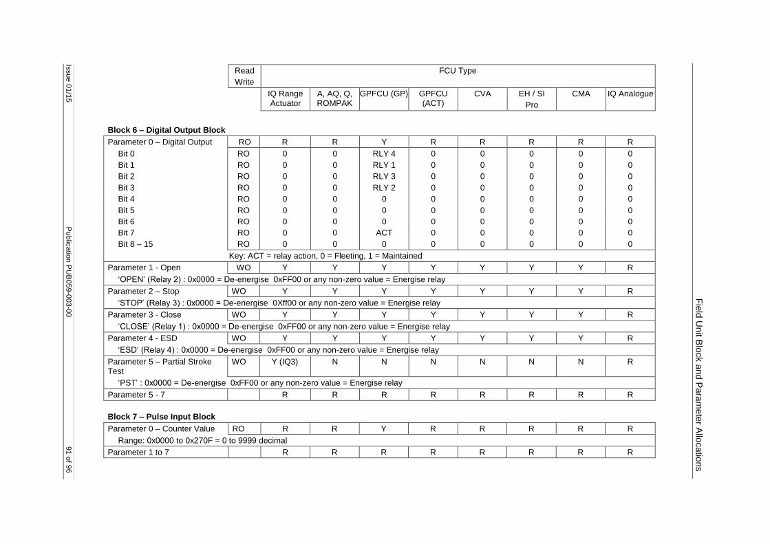
Issue 0
1/1
5
Public
atio
n P
UB
059
-003-0
0
91 o
f 96
Fie
ld U
nit B
lock a
nd P
ara
mete
r Allo
catio
ns
Read
Write
FCU Type
IQ Range Actuator
A, AQ, Q, ROMPAK
GPFCU (GP) GPFCU (ACT)
CVA EH / SI
Pro
CMA IQ Analogue
Block 6 – Digital Output Block
Parameter 0 – Digital Output RO R R Y R R R R R
Bit 0 RO 0 0 RLY 4 0 0 0 0 0
Bit 1 RO 0 0 RLY 1 0 0 0 0 0
Bit 2 RO 0 0 RLY 3 0 0 0 0 0
Bit 3 RO 0 0 RLY 2 0 0 0 0 0
Bit 4 RO 0 0 0 0 0 0 0 0
Bit 5 RO 0 0 0 0 0 0 0 0
Bit 6 RO 0 0 0 0 0 0 0 0
Bit 7 RO 0 0 ACT 0 0 0 0 0
Bit 8 – 15 RO 0 0 0 0 0 0 0 0
Key: ACT = relay action, 0 = Fleeting, 1 = Maintained
Parameter 1 - Open WO Y Y Y Y Y Y Y R
‘OPEN’ (Relay 2) : 0x0000 = De-energise 0xFF00 or any non-zero value = Energise relay
Parameter 2 – Stop WO Y Y Y Y Y Y Y R
‘STOP’ (Relay 3) : 0x0000 = De-energise 0Xff00 or any non-zero value = Energise relay
Parameter 3 - Close WO Y Y Y Y Y Y Y R
‘CLOSE’ (Relay 1) : 0x0000 = De-energise 0xFF00 or any non-zero value = Energise relay
Parameter 4 - ESD WO Y Y Y Y Y Y Y R
‘ESD’ (Relay 4) : 0x0000 = De-energise 0xFF00 or any non-zero value = Energise relay
Parameter 5 – Partial Stroke Test
WO Y (IQ3) N N N N N N R
‘PST’ : 0x0000 = De-energise 0xFF00 or any non-zero value = Energise relay
Parameter 5 - 7 R R R R R R R R
Block 7 – Pulse Input Block
Parameter 0 – Counter Value RO R R Y R R R R R
Range: 0x0000 to 0x270F = 0 to 9999 decimal
Parameter 1 to 7 R R R R R R R R

92 o
f 96
Public
atio
n P
UB
059
-003-0
0
Issues 0
1/1
5
Pakscan P
3 w
ith P
720 M
od
ule
Mod
bus In
terfa
ce S
pecific
atio
n
Read
Write
FCU Type
IQ Range Actuator
A, AQ, Q, ROMPAK
GPFCU (GP) GPFCU (ACT)
CVA EH / SI
Pro
CMA IQ Analogue
Block 8 – IQ Range Digital Output operation
Parameter 0 - R R R R R R R R
Parameter 1 - WO Y R R R R R R R
Digital output 1 : 0x0000 = De-energise 0xFF00 or any non-zero value = Energise relay
Parameter 2 - WO Y R R R R R R R
Digital output 2 : 0x0000 = De-energise 0xFF00 or any non-zero value = Energise relay
Parameter 3 - WO Y R R R R R R R
Digital output 3 : 0x0000 = De-energise 0xFF00 or any non-zero value = Energise relay
Parameter 4 - WO Y R R R R R R R
Digital output 4 : 0x0000 = De-energise 0xFF00 or any non-zero value = Energise relay
Parameter 5-7 - R R R R R R R R

Issue 0
1/1
5
Public
atio
n P
UB
059
-003-0
0
93 o
f 96
Fie
ld U
nit B
lock a
nd P
ara
mete
r Allo
catio
ns
Read
Write
FCU Type
IQ Range Actuator
A, AQ, Q, ROMPAK
GPFCU (GP) GPFCU (ACT)
CVA EH / SI
Pro
CMA IQ Analogue
Block 9 – 12 bit Analogue Input 1 Block
Para’ 0 – Analogue Input 1 R/O Y(IQ3) R Y R R R R Y
Range: 0x0000 = 0%, 0x0FFF = 100%
Para’ 1 – Deviation Threshold R/W Y(IQ3) R Y R R R R Y
Range: 0x0000 = 0%, 0x00FF = 100%, (0 = disable)
Para’ 2 – Update Timeout R/W Y(IQ3) R Y R R R R Y
Range: 0x0000 = 0 sec, 0x00FF = 255 sec (0 = disable)
Para’ 3 – AI 1 Min (0% input) R/W R R Y R R R R Y
Para’ 4 – AI 1 Max (100% i/p) R/W R R Y R R R R Y
Para; 5 – Raw An I/P 1 RO R R Y R R R R Y
Parameter 6 and 7 R R R R R R R R
Block 10 – 12 bit Analogue Input 2 Block
Para’ 0 – Analogue Input 2 R/O Y(IQ3) R Y R R R R Y
Range: 0x0000 = 0%, 0x0FFF = 100%
Para’ 1 – Deviation Threshold R/W Y(IQ3) R Y R R R R Y
Range: 0x0000 = 0%, 0x00FF = 100%, (0 = disable)
Para’ 2 – Update Timeout R/W Y(IQ3) R Y R R R R Y
Range: 0x0000 = 0 sec, 0x00FF = 255 sec (0 = disable)
Para’ 3 – AI 2 Min (0% input) R/W R R Y R R R R Y
Para’ 4 – AI 2 Max (100% i/p) R/W R R Y R R R R Y
Para; 5 – Raw An I/P 2 RO R R Y R R R R Y
Parameter 6 and 7 R R R R R R R R

94 o
f 96
Public
atio
n P
UB
059
-003-0
0
Issues 0
1/1
5
Pakscan P
3 w
ith P
720 M
od
ule
Mod
bus In
terfa
ce S
pecific
atio
n
Read
Write
FCU Type
IQ Range Actuator
A, AQ, Q, ROMPAK
GPFCU (GP) GPFCU (ACT)
CVA EH / SI
Pro
CMA IQ Analogue
Block 11 – 12 bit Analogue Output Block
Para’ 0 – Analogue Output R/W R R Y R R R R R
Range: 0x0000 = 0%, 0x0FFF = 100%
Para’ 1 – 0% Calibration R/W R R Y R R R R R
Range: 0x0000 to 0x0FFF = Value at 0%
Para’ 1 – 100% Calibration R/W R R Y R R R R R
Range: 0x0000 to 0x0FFF = Value at 100%
Parameter 3 to 7 R R R R R R R R
Block 12 – Historical Torque Profile – Opening Direction
The IQ Range Actuator is able to report 8 torque values related to valve position across the valve stroke. Position 0 and 100% are not used as these may be set to full torque for a torque seating valve. Torque readings are available for 6%, 19%, 31%, 44%, 56%, 69%, 81%, and 94% positions. The following parameters contain this data for the OPENING direction of travel - note that they only update if a complete stroke of the valve is made and contain the last profile only.
Range: 0000 = 0% rated torque, 00FF = 120% rated torque
Para’ 0 - 6% RO Y R R R Y Y R R
Para’ 1 - 19% RO Y R R R Y Y R R
Para’ 2 - 31% RO Y R R R Y Y R R
Para’ 3 - 44% RO Y R R R Y Y R R
Para’ 4 - 56% RO Y R R R Y Y R R
Para’ 5 - 69% RO Y R R R Y Y R R
Para’ 6 - 81% RO Y R R R Y Y R R
Para’ 7 - 94% RO Y R R R Y Y R R

Issue 0
1/1
5
Public
atio
n P
UB
059
-003-0
0
95 o
f 96
Fie
ld U
nit B
lock a
nd P
ara
mete
r Allo
catio
ns
Read
Write
FCU Type
IQ Range Actuator
A, AQ, Q, ROMPAK
GPFCU (GP) GPFCU (ACT)
CVA EH / SI
Pro
CMA IQ Analogue
Block 13 – Historical Torque Profile – Closing Direction
The IQ Range Actuator is able to report 8 torque values related to valve position across the valve stroke. Position 0 and 100% are not used as these may be set to full torque for a torque seating valve. Torque readings are available for 6%, 19%, 31%, 44%, 56%, 69%, 81%, and 94% positions. The following parameters contain this data for the CLOSING direction of travel - note that they only update if a complete stroke of the valve is made and contain the last profile only.
Range: 0000 = 0% rated torque, 00FF = 120% rated torque
Para’ 0 - 6% RO Y R R R Y Y R R
Para’ 1 - 19% RO Y R R R Y Y R R
Para’ 2 - 31% RO Y R R R Y Y R R
Para’ 3 - 44% RO Y R R R Y Y R R
Para’ 4 - 56% RO Y R R R Y Y R R
Para’ 5 - 69% RO Y R R R Y Y R R
Para’ 6 - 81% RO Y R R R Y Y R R
Para’ 7 - 94% RO Y R R R Y Y R R
Block 14 – Historical Torque Profile – Closing Direction
Para’ 0 – Current Torque R/O Y R R R Y Y R R
Range: 0x0000 = 0%, 0x00FF = 120%
Para’ 1 – Deviation Threshold R/W Y R R R Y Y R R
Range: 0x0000 = 0%, 0x00FF = 100%,
Para’ 2 – Update Timeout R/W Y R R R Y Y R R
Range: 0x0001 = 1 minute, 0x00FF = 255 minutes (0 = disable)
Para’ 3 – Filter R/W Y R R R Y Y R R
Data: 0x0000 = Off, 0x00FF = On, Automatic torque reporting is only available with the filter Off
Para’ 4 – Profile Counters M R R R M M R R
Bits 8-15 = Open counter, Bits 7-0 = Close counter (available from the master station only)
Parameter 5 to 7 R R R R R R R R
Block 15 to 31 – Reserved
Block 15 - 31 Parameter 1 - 7 R R R R R R R R

UK
Rotork PLC
Tel: +44 (0) 1225 733 200
Fax: +44 (0) 1225 333 467
e-mail: [email protected]
USA Rotork Controls Inc.
Tel: +1 (585) 247 2304
Fax: +1 (585) 247 2308
e-mail: [email protected]
http://www.rotork.com
Rotork reserves the right to amend and change specifications without prior notice. Published data may be subject to change