Embed Size (px)
Citation preview

Modbus Ethernet Interface
Version 4.0.4.xRevision B

OSIsoft, LLC 777 Davis St., Suite 250San Leandro, CA 94577 USATel: (01) 510-297-5800Fax: (01) 510-357-8136Web: http://www.osisoft.com
OSIsoft Australia • Perth, AustraliaOSIsoft Europe GmbH • Frankfurt, GermanyOSIsoft Asia Pte Ltd. • Singapore OSIsoft Canada ULC • Montreal & Calgary, CanadaOSIsoft, LLC Representative Office • Shanghai, People’s Republic of ChinaOSIsoft Japan KK • Tokyo, JapanOSIsoft Mexico S. De R.L. De C.V. • Mexico City, MexicoOSIsoft do Brasil Sistemas Ltda. • Sao Paulo, Brazil
Modbus Ethernet InterfaceCopyright: © 1998-2023 OSIsoft, LLC. All rights reserved. No part of this publication may be reproduced, stored in a retrieval system, or transmitted, in any form or by any means, mechanical, photocopying, recording, or otherwise, without the prior written permission of OSIsoft, LLC.
OSIsoft, the OSIsoft logo and logotype, PI Analytics, PI ProcessBook, PI DataLink, ProcessPoint, PI Asset Framework(PI-AF), IT Monitor, MCN Health Monitor, PI System, PI ActiveView, PI ACE, PI AlarmView, PI BatchView, PI Data Services, PI Manual Logger, PI ProfileView, PI WebParts, ProTRAQ, RLINK, RtAnalytics, RtBaseline, RtPortal, RtPM, RtReports and RtWebParts are all trademarks of OSIsoft, LLC. All other trademarks or trade names used herein are the property of their respective owners.
U.S. GOVERNMENT RIGHTSUse, duplication or disclosure by the U.S. Government is subject to restrictions set forth in the OSIsoft, LLC license agreement and as provided in DFARS 227.7202, DFARS 252.227-7013, FAR 12.212, FAR 52.227, as applicable. OSIsoft, LLC.
Published: 05/2011

Table of Contents
Terminology....................................................................................................................ixInterface Specific Terms.................................................................................... ixGeneral Terms.................................................................................................. ix
Chapter 1. Introduction...................................................................................................1Reference Manuals............................................................................................1Supported Features...........................................................................................2Diagram of Hardware Connection......................................................................5
Chapter 2. Principles of Operation................................................................................7
Chapter 3. Installation Checklist....................................................................................9Data Collection Steps.........................................................................................9Interface Diagnostics........................................................................................10Advanced Interface Features...........................................................................11
Chapter 4. Interface Installation...................................................................................13Naming Conventions and Requirements..........................................................13Interface Directories.........................................................................................14
PIHOME Directory Tree.........................................................................14Interface Installation Directory...............................................................14
Interface Installation Procedure.......................................................................14Installing Interface as a Windows Service........................................................14Installing Interface Service with PI Interface Configuration Utility....................15
Service Configuration............................................................................15Installing Interface Service Manually.....................................................18
Chapter 5. Upgrading From Previous Versions.........................................................19Configuration File Generator............................................................................19
PI Server Selection................................................................................19PI Point Selection..................................................................................20Default Parameters................................................................................22Save......................................................................................................24
Point Upgrade Requirements...........................................................................25Square Root...........................................................................................25Data Type Conversion...........................................................................261. Update Instrument Tags.................................................................27
Chapter 6. Digital States...............................................................................................29
Chapter 7. PointSource.................................................................................................31
Modbus Ethernet Interface iii

Chapter 8. PI Point Configuration................................................................................33Point Attributes.................................................................................................33
Tag........................................................................................................33PointSource...........................................................................................33PointType...............................................................................................34Location1...............................................................................................34Location2...............................................................................................34Location3...............................................................................................34Location4...............................................................................................39Location5...............................................................................................39InstrumentTag........................................................................................39ExDesc..................................................................................................41Scan......................................................................................................44SourceTag.............................................................................................44Zero.......................................................................................................44Span......................................................................................................45Shutdown...............................................................................................45Convers.................................................................................................45SquareRoot............................................................................................45
Input Tag Configuration....................................................................................47Optimization...........................................................................................48
Output Tag Configuration.................................................................................48Example 1..............................................................................................48Example 2..............................................................................................51Optimization...........................................................................................51
Order of Data Pre/Post Processing..................................................................52Output Points...................................................................................................52
Trigger Method 1 (Recommended)........................................................52Trigger Method 2...................................................................................53
Chapter 9. Startup Command File...............................................................................55Configuring the Interface with PI ICU...............................................................55
ModbusE Interface page........................................................................57Command-line Parameters..............................................................................59Logging Flags..................................................................................................65Run-time Configuration Flag............................................................................66Reduced Logging.............................................................................................66Sample PIModbusE.bat File.............................................................................67
Chapter 10. Interface Configuration File...................................................................69Modbus Interface Configurator.........................................................................69
Open......................................................................................................70Save......................................................................................................71Preview..................................................................................................71Edit........................................................................................................72Interface Tab..........................................................................................72Nodes Tab.............................................................................................78
Configuration File Parameters.........................................................................83Trace Flags......................................................................................................86Sample ModbusEConfig.csv File.....................................................................87
Chapter 11. UniInt Failover Configuration................................................................89
Modbus Ethernet Interface iv

Introduction......................................................................................................89Quick Overview......................................................................................90
Synchronization through a Shared File (Phase 2)............................................91Configuring Synchronization through a Shared File (Phase 2)........................92Configuring UniInt Failover through a Shared File (Phase 2)...........................95
Start-Up Parameters..............................................................................95Failover Control Points..........................................................................97PI Tags..................................................................................................98
Detailed Explanation of Synchronization through a Shared File (Phase 2)....102Steady State Operation........................................................................103
Failover Configuration Using PI ICU..............................................................105Create the Interface Instance with PI ICU......................................................105Configuring the UniInt Failover Startup Parameters with PI ICU....................106Creating the Failover State Digital State Set..................................................106
Using the PI ICU Utility to create Digital State Set...............................107Using the PI SMT 3 Utility to create Digital State Set..........................107
Creating the UniInt Failover Control and Failover State Tags (Phase 2)........110
Chapter 12. Interface Node Clock............................................................................111
Chapter 13. Security..................................................................................................113Windows........................................................................................................113
Chapter 14. Starting / Stopping the Interface.........................................................115Starting Interface as a Service.......................................................................115Stopping Interface Running as a Service.......................................................115
Chapter 15. Buffering................................................................................................117Which Buffering Application to Use................................................................117How Buffering Works.....................................................................................118Buffering and PI Server Security....................................................................118Enabling Buffering on an Interface Node with the ICU...................................119
Choose Buffer Type.............................................................................119Buffering Settings................................................................................120Buffered Servers..................................................................................122Installing Buffering as a Service...........................................................125
Chapter 16. Interface Diagnostics Configuration...................................................129Scan Class Performance Points....................................................................129Performance Counters Points........................................................................132
Performance Counters.........................................................................133Performance Counters for both (_Total) and (Scan Class x)...............133Performance Counters for (_Total) only...............................................135Performance Counters for (Scan Class x) only....................................137
Interface Health Monitoring Points.................................................................139I/O Rate Point................................................................................................144Interface Status Point.....................................................................................147
Appendix A. Error and Informational Messages....................................................149Message Logs................................................................................................149
Modbus Ethernet Interface v

Table of Contents
ModbusE Messages.......................................................................................149Informational........................................................................................149Warning...............................................................................................150Error.....................................................................................................154
System Errors and PI Errors..........................................................................163UniInt Failover Specific Error Messages........................................................164
Informational........................................................................................164Errors (Phase 1 & 2)............................................................................165Errors (Phase 2)..................................................................................166
Appendix B. PI SDK Options....................................................................................167
Appendix C. Floating Point Representation...........................................................169Floating Point, Data Type 4............................................................................170Floating Point, Data Type 5............................................................................170Floating Point, Data Type 6............................................................................170Floating Point, Data Type 7............................................................................170
Floating Point Data Represented as 4-byte Integers...........................170Siemens Floating-Point Representation, Data Type 8...................................171Function Code 65...........................................................................................171Enron Floating Point Type..............................................................................172
Appendix D. Modbus Message Packets..................................................................173Function Code 1: Read Coils.........................................................................174Function Code 2: Read Discrete Inputs.........................................................174Function Code 3: Read Holding Registers.....................................................175Function Code 4: Read Input Registers.........................................................175Function Code 5: Write Single Coil................................................................176Function Code 6: Write Single Register.........................................................176Function Code 15: Write Multiple Coils..........................................................177Function Code 16: Write Multiple Registers...................................................177
Appendix E. Modbus Exception Responses..........................................................179Exception Response Packet..........................................................................179Exception Codes............................................................................................180
Appendix F. Tag Optimization..................................................................................183Input Tags......................................................................................................183
Tag Groups..........................................................................................183Optimization.........................................................................................184
Output Tags...................................................................................................186Tag Groups..........................................................................................186Tag Configuration Optimization...........................................................187Automatic Optimization........................................................................188
Scan Classes.................................................................................................188
Appendix G. Technical Support and Resources....................................................191Before You Call or Write for Help.........................................................191Help Desk and Telephone Support......................................................191Search Support....................................................................................192
vi

Email-based Technical Support...........................................................192Online Technical Support.....................................................................192Remote Access....................................................................................193On-site Service....................................................................................193Knowledge Center...............................................................................193Upgrades.............................................................................................193OSIsoft Virtual Campus (vCampus).....................................................193
Appendix H. Revision History..................................................................................195
Modbus Ethernet Interface vii

Terminology
To understand this interface manual, you should be familiar with the terminology used in this document.
Interface Specific Terms
Ethernet NodeEthernet node refers to an IP address or a hostname along with its corresponding service port. An Ethernet node is in the form “IP Address:port” or “Hostname:port”. Since a user can configure the interface to connect to an Ethernet device by using either the IP address and port or a hostname and port, the document will use the terms “Ethernet node” or “node” to signify both methods of connecting to devices.
Tag GroupTag group refers to a group of similar tags in which the only important difference between each tag is the Location5 (data offset) attribute. When a group of tags has the same InstrumentTag (Ethernet node), Location2 (PLC node ID), Location3 (Function Code and Data Type) and Location4 (Scan Class) attributes they are subject to being members of the same tag group. In the case of input tags the qualifying factor is that the data offset is within a range of data offsets that is dependent on the data type. In the case of output tags the qualifying factor is that the data offset is contiguous with the data offset of other tags within the tag group.
General Terms
BufferingBuffering refers to an Interface Node’s ability to store temporarily the data that interfaces collect and to forward these data to the appropriate PI Servers.
N-Way BufferingIf you have PI Servers that are part of a PI Collective, PIBufss supports n-way buffering. N-way buffering refers to the ability of a buffering application to send the same data to each of the PI Servers in a PI Collective. (Bufserv also supports n-way buffering to multiple PI Servers however it does not guarantee identical archive records since point compressions attibutes could be different between PI Servers. With this in mind, OSIsoft recommends that you run PIBufss instead.)
ICUICU refers to the PI Interface Configuration Utility. The ICU is the primary application that you use to configure PI interface programs. You must install the ICU on the same computer on which an interface runs. A single copy of the ICU manages all of the interfaces on a particular computer.
Modbus Ethernet Interface ix

Terminology
You can configure an interface by editing a startup command file. However, OSIsoft discourages this approach. Instead, OSIsoft strongly recommends that you use the ICU for interface management tasks.
ICU ControlAn ICU Control is a plug-in to the ICU. Whereas the ICU handles functionality common to all interfaces, an ICU Control implements interface-specific behavior. Most PI interfaces have an associated ICU Control.
Interface NodeAn Interface Node is a computer on which
the PI API and/or PI SDK are installed, and
PI Server programs are not installed.
PI APIThe PI API is a library of functions that allow applications to communicate and exchange data with the PI Server. All PI interfaces use the PI API.
PI CollectiveA PI Collective is two or more replicated PI Servers that collect data concurrently. Collectives are part of the High Availability environment. When the primary PI Server in a collective becomes unavailable, a secondary collective member node seamlessly continues to collect and provide data access to your PI clients.
PIHOMEPIHOME refers to the directory that is the common location for PI 32-bit client applications.
A typical PIHOME on a 32-bit operating system is C:\Program Files\PIPC.
A typical PIHOME on a 64-bit operating system is C:\Program Files (x86)\PIPC.
PI 32-bit interfaces reside in a subdirectory of the Interfaces directory under PIHOME.
For example, files for the 32-bit Modbus Ethernet Interface are in
[PIHOME]\PIPC\Interfaces\ModbusE.
This document uses [PIHOME] as an abbreviation for the complete PIHOME or PIHOME64 directory path. For example, ICU files in [PIHOME]\ICU.
PIHOME64PIHOME64 is found only on a 64-bit operating system and refers to the directory that is the common location for PI 64-bit client applications.
A typical PIHOME64 is C:\Program Files\PIPC.
PI 64-bit interfaces reside in a subdirectory of the Interfaces directory under PIHOME64.
For example, files for a 64-bit Modbus Ethernet Interface would be found in
C:\Program Files\PIPC\Interfaces\ModbusE.
This document uses [PIHOME] as an abbreviation for the complete PIHOME or PIHOME64 directory path. For example, ICU files in [PIHOME]\ICU.
x
PI Message LogThe PI message Log is the file to which OSIsoft interfaces based on UniInt 4.5.0.x and later writes informational, debug and error message. When a PI interface runs, it writes to the local PI message log. This message file can only be viewed using the PIGetMsg utility. See the UniInt Interface Message Logging.docx file for more information on how to access these messages.
PI SDKThe PI SDK is a library of functions that allow applications to communicate and exchange data with the PI Server. Some PI interfaces, in addition to using the PI API, require the use of the PI SDK.
PI Server NodeA PI Server Node is a computer on which PI Server programs are installed. The PI Server runs on the PI Server Node.
PI SMTPI SMT refers to PI System Management Tools. PI SMT is the program that you use for configuring PI Servers. A single copy of PI SMT manages multiple PI Servers. PI SMT runs on either a PI Server Node or a PI Interface Node.
Pipc.logThe pipc.log file is the file to which OSIsoft applications write informational and error messages. When a PI interface runs, it writes to the pipc.log file. The ICU allows easy access to the pipc.log.
PointThe PI point is the basic building block for controlling data flow to and from the PI Server. For a given timestamp, a PI point holds a single value.
A PI point does not necessarily correspond to a “point” on the foreign device. For example, a single “point” on the foreign device can consist of a set point, a process value, an alarm limit, and a discrete value. These four pieces of information require four separate PI points.
ServiceA Service is a Windows program that runs without user interaction. A Service continues to run after you have logged off from Windows. It has the ability to start up when the computer itself starts up.
The ICU allows you to configure a PI interface to run as a Service.
Tag (Input Tag and Output Tag)The tag attribute of a PI point is the name of the PI point. There is a one-to-one correspondence between the name of a point and the point itself. Because of this relationship, PI System documentation uses the terms “tag” and “point” interchangeably.
Interfaces read values from a device and write these values to an Input Tag. Interfaces use an Output Tag to write a value to the device.
Modbus Ethernet Interface xi

Chapter 1. Introduction
This manual is a description of the Modbus Ethernet Interface for Windows, ModbusE. The interface can be run either on a PI 3 server node or on a PI Interface node that communicates to a PI server. Only Modbus communication with an Ethernet device is supported.
The interface is designed to read data from a PLC on a periodic or event basis and to send output data (commands to the PLC) on an event basis. The ModbusE Interface attempts to optimize scanning performance by grouping input tags with the same scan rate, PLC destination node, and function code.
This interface is an upgrade to the ModbusE Interface version 2.x. It contains several new features including scalability, run-time configuration, Phase 2 failover and debug tracing separated from logging.
Note: The value of [PIHOME] variable for the 32-bit interface will depend on whether the interface is being installed on a 32-bit operating system (C:\Program Files\PIPC) or a 64-bit operating system (C:\Program Files (x86)\PIPC).
The value of [PIHOME64] variable for a 64-bit interface will be C:\Program Files\PIPC on the 64-bit Operating system.
In this documentation [PIHOME] will be used to represent the value for either [PIHOME] or [PIHOME64]. The value of [PIHOME] is the directory which is the common location for PI client applications.
Note: Throughout this manual there are references to where messages are written by the interface which is the PIPC.log. This interface has been built against a of UniInt version (4.5.0.59 and later) which now writes all its messages to the local PI Message log.
Please note that any place in this manual where it references PIPC.log should now refer to the local PI message log. Please see the document UniInt Interface Message Logging.docx in the %PIHOME%\Interfaces\UniInt directory for more details on how to access these messages.
Reference Manuals
OSIsoft PI Server manuals
PI API Installation manual
UniInt Interface User Manual
Modbus Ethernet Interface 1

Vendor Modbus Application Protocol Specification V1.1b
Modbus Protocol Reference Guide (AEG Schneider Automation)
Supported Features
Feature Support
Part Number PI-IN-MO-EPLC-NTI
* Platforms 32-bit Interface 64-bit Interface
Windows XP
32-bit OS Yes No
64-bit OS Yes (Emulation Mode) No
Windows 2003 Server
32-bit OS Yes No
64-bit OS Yes (Emulation Mode) No
Windows Vista
32-bit OS Yes No
64-bit OS Yes (Emulation Mode) No
Windows 2008
32-bit OS Yes No
64-bit OS Yes (Emulation Mode) No
Windows 2008 R2
64-bit OS Yes (Emulation Mode) No
Windows 7
32-bit OS Yes No
64-bit OS Yes (Emulation Mode) No
Auto Creates PI Points No
Point Builder Utility No
ICU Control Yes
PI Point Types float16 / float32 / float64 / int16 / int32 / digital
Sub-second Timestamps Yes
Sub-second Scan Classes Yes
Automatically Incorporates PI Point Attribute Changes
Yes
Exception Reporting Yes
Outputs from PI Yes
Inputs to PI: Scan-based / Unsolicited / Event Tags
Scan-based / Event Tags
Supports Questionable Bit No
Supports Multi-character PointSource Yes
Maximum Point Count No
* Uses PI SDK No
Modbus Ethernet Interface 2
Feature Support
PINet String Support No
* Source of Timestamps PI Home Node
History Recovery No
* UniInt-based* Disconnected Startup* SetDeviceStatus
YesYesYes
Failover UniInt Failover (Phase 2 Cold, Warm and Hot); Server-level failover (Cold and Warm)
Vendor Software Required on PI Interface Node / PINet Node
No
Vendor Software Required on Foreign Device
No
Vendor Hardware Required No
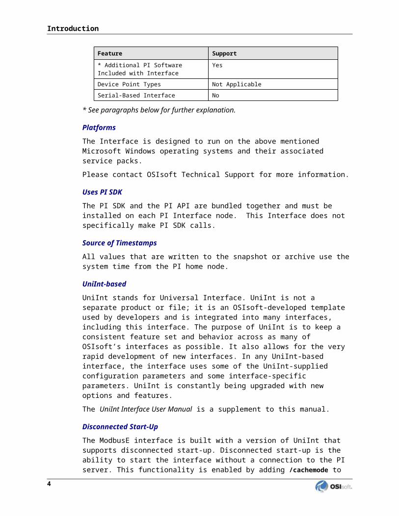
* Additional PI Software Included with Interface
Yes
Device Point Types Not Applicable
Serial-Based Interface No
* See paragraphs below for further explanation.
PlatformsThe Interface is designed to run on the above mentioned Microsoft Windows operating systems and their associated service packs.
Please contact OSIsoft Technical Support for more information.
Uses PI SDKThe PI SDK and the PI API are bundled together and must be installed on each PI Interface node. This Interface does not specifically make PI SDK calls.
Source of TimestampsAll values that are written to the snapshot or archive use the system time from the PI home node.
UniInt-basedUniInt stands for Universal Interface. UniInt is not a separate product or file; it is an OSIsoft-developed template used by developers and is integrated into many interfaces, including this interface. The purpose of UniInt is to keep a consistent feature set and behavior across as many of OSIsoft’s interfaces as possible. It also allows for the very rapid development of new interfaces. In any UniInt-based interface, the interface uses some of the UniInt-supplied configuration parameters and some interface-specific parameters. UniInt is constantly being upgraded with new options and features.
The UniInt Interface User Manual is a supplement to this manual.
Disconnected Start-UpThe ModbusE interface is built with a version of UniInt that supports disconnected start-up. Disconnected start-up is the ability to start the interface without a connection to the PI server. This functionality is enabled by adding /cachemode to the list of start-up parameters or by
Modbus Ethernet Interface 3

Introduction
enabling disconnected startup using the ICU. Refer to the UniInt Interface User Manual for more details on UniInt Disconnect startup.
SetDeviceStatusThe interface supports UniInt device status tags. The device status Health tag has the string “[UI_DEVSTAT]” in the extended descriptor (Exdesc) Point Attribute. Please refer to the UniInt Interface User Manual.doc file for more information on how to configure health points. Alternatively, Health tags can be configured with the PI Interface Configuration Utility.
Device status tags can be configured to monitor the status of the devices to which the interface connects. Strings of the following form can be written to the device status tag. Note that the “# |” at the beginning of each error string is for internal use for an application that parses this string.
“Good” - This value indicates that the Interface is able to connect to all of the devices referenced in the Interface’s point configuration. A value of “Good” does not mean that all tags are receiving good values, but it is a good indication that there are no hardware or network problems.
“1 | Starting” – The interface will remain in this status until it has successfully collected data from its first scan. Interfaces that collect data infrequently may stay in this status for a long time.
“Zero devices are currently communicating with the interface.” - This value indicates that the Interface cannot communicate with any of the devices.
“# device(s) failed all of their retries while requesting data.” - This value indicates that the Interface cannot communicate with some of the devices. The number of devices that failed their retries will be recorded and logged.
“4 | Intf Shutdown” - The Interface has shut down.
Failover UniInt Failover Support
UniInt Phase 2 Failover provides support for cold, warm, or hot failover configurations. The Phase 2 hot failover results in a no data loss solution for bi-directional data transfer between the PI Server and the Data Source given a single point of failure in the system architecture similar to Phase 1. However, in warm and cold failover configurations, you can expect a small period of data loss during a single point of failure transition. This failover solution requires that two copies of the interface be installed on different interface nodes collecting data simultaneously from a single data source. Phase 2 Failover requires each interface have access to a shared data file. Failover operation is automatic and operates with no user interaction. Each interface participating in failover has the ability to monitor and determine liveliness and failover status. To assist in administering system operations, the ability to manually trigger failover to a desired interface is also supported by the failover scheme.
The failover scheme is described in detail in the UniInt Interface User Manual, which is a supplement to this manual. Details for configuring this Interface to use failover are described in the UniInt Failover Configuration section of this manual.
4

This interface supports UniInt Failover (Phase 2 Cold, Warm and Hot); Server-level failover (Cold and Warm).
Additional PI SoftwareThis interface comes with support utilities for configuration purposes and upgrading from previous versions of the interface. These utilities are described in detail in later chapters of this document:
The Modbus Ethernet Interface Configurator is used to configure the interface and each Ethernet node that the interface supports.
The Modbus Ethernet Configuration File Generator is used to generate an initial interface configuration file from PI Points used by instances of the previous version of the interface.
Diagram of Hardware Connection
Modbus Ethernet Interface 5

Chapter 2. Principles of Operation
For proper interface operation, the user must configure input points (input tags) and/or output points (output tags) on a PI home node. Input tags are used to receive data from PLC nodes. Data are received either at a given frequency or after a value is sent to a "trigger" tag. Output tags are used to send commands to a PLC. A command is sent to a PLC after a value is sent to a "source" tag or after a value is sent to the output tag itself, depending on the configuration of the output tag. All values that are written to the snapshot or archive use the system time from the PI home node. If a communication error occurs while attempting to read data from a PLC, the interface will attempt to re-establish communication until it is successful.
At startup, the interface scans the PI Point Database for all associated points and builds its own point list. During runtime, the interface continues to check the PI Point Database for point updates and modifies its point list accordingly. If the Scan field of any point on the point list is set to zero, the point is removed from the point list. The point is added once again after the Scan field is turned back on. If neither a fixed scan rate nor a valid trigger tag is found for a given point, the point will not be added to the list.
The interface is designed to optimize data transfer and minimize communication traffic by collecting input data into groups. Input points that are configured with the same function code, scan rate, and PLC destination node are grouped together. When the amount of data that is requested for a given group exceeds the maximum data transfer size (up to 250 bytes) a new group is created. The proper use of PLC memory can greatly enhance the efficiency and overall data throughput of the interface.
UniInt FailoverThis interface supports UniInt failover. Refer to the UniInt Failover Configuration section of this document for configuring the interface for failover.
Modbus Ethernet Interface 7
Chapter 3. Installation Checklist
If you are familiar with running PI data collection interface programs, this checklist helps you get the Interface running. If you are not familiar with PI interfaces, return to this section after reading the rest of the manual in detail.
This checklist summarizes the steps for installing this Interface. You need not perform a given task if you have already done so as part of the installation of another interface. For example, you only have to configure one instance of Buffering for every Interface Node regardless of how many interfaces run on that node.
The Data Collection Steps below are required. Interface Diagnostics and Advanced Interface Features are optional.
Data Collection Steps
1. Confirm that you can use PI SMT to configure the PI Server. You need not run PI SMT on the same computer on which you run this Interface.
2. If you are running the Interface on an Interface Node, edit the PI Server’s Trust Table to allow the Interface to write data.
3. Run the installation kit for the PI Interface Configuration Utility (ICU) on the interface node if the ICU will be used to configure the interface. This kit runs the PI SDK installation kit, which installs both the PI API and the PI SDK.
4. Run the installation kit for this Interface. This kit also runs the PI SDK installation kit which installs both the PI API and the PI SDK if necessary.
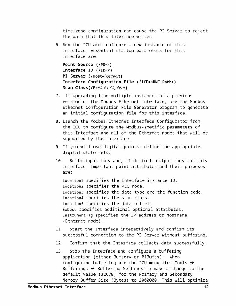
5. If you are running the Interface on an Interface Node, check the computer’s time zone properties. An improper time zone configuration can cause the PI Server to reject the data that this Interface writes.
6. Run the ICU and configure a new instance of this Interface. Essential startup parameters for this Interface are:
Point Source (/PS=x)Interface ID (/ID=#)PI Server (/Host=host:port) Interface Configuration File (/ICF=<UNC Path>) Scan Class(/F=##:##:##,offset)
7. If upgrading from multiple instances of a previous version of the Modbus Ethernet Interface, use the Modbus Ethernet Configuration File Generator program to generate an initial configuration file for this interface.
Modbus Ethernet Interface 9

8. Launch the Modbus Ethernet Interface Configurator from the ICU to configure the Modbus-specific parameters of this Interface and all of the Ethernet nodes that will be supported by the Interface.
9. If you will use digital points, define the appropriate digital state sets.
10. Build input tags and, if desired, output tags for this Interface. Important point attributes and their purposes are:
Location1 specifies the Interface instance ID.Location2 specifies the PLC node.Location3 specifies the data type and the function code.Location4 specifies the scan class.Location5 specifies the data offset. ExDesc specifies additional optional attributes.InstrumentTag specifies the IP address or hostname (Ethernet node).
11. Start the Interface interactively and confirm its successful connection to the PI Server without buffering.
12. Confirm that the Interface collects data successfully.
13. Stop the Interface and configure a buffering application (either Bufserv or PIBufss). When configuring buffering use the ICU menu item Tools Buffering… Buffering Settings to make a change to the default value (32678) for the Primary and Secondary Memory Buffer Size (Bytes) to 2000000. This will optimize the throughput for buffering and is recommended by OSIsoft.
14. Start the buffering application and the Interface. Confirm that the Interface works together with the buffering application by either physically removing the connection between the Interface Node and the PI Server Node or by stopping the PI Server.
15. Configure the Interface to run as a Service. Confirm that the Interface runs properly as a Service.
16. Restart the Interface Node and confirm that the Interface and the buffering application restart.
Interface Diagnostics
17. Configure Scan Class Performance points.
18. Install the PI Performance Monitor Interface (Full Version only) on the Interface Node.
19. Configure Performance Counter points.
20. Configure UniInt Health Monitoring points
21. Configure the I/O Rate point.
22. Install and configure the Interface Status Utility on the PI Server Node.
23. Configure the Interface Status point.
Modbus Ethernet Interface 10

Advanced Interface Features
1. Configure the interface for Disconnected Startup. Refer to the UniInt Interface User Manual for more details on UniInt Disconnect startup.
2. Configure UniInt Failover, see the UniInt Failover Configuration; section in this document for details related to configuring the interface for failover.
Modbus Ethernet Interface 11

Chapter 4. Interface Installation
OSIsoft recommends that interfaces be installed on PI Interface Nodes instead of directly on the PI Server node. A PI Interface Node is any node other than the PI Server node where the PI Application Programming Interface (PI API) is installed (see the PI API manual). With this approach, the PI Server need not compete with interfaces for the machine’s resources. The primary function of the PI Server is to archive data and to service clients that request data.
After the interface has been installed and tested, Buffering should be enabled on the PI Interface Node. Buffering refers to either PI API Buffer Server (Bufserv) or the PI Buffer Subsystem (PIBufss). For more information about Buffering see the Buffering section of this manual.
In most cases, interfaces on PI Interface Nodes should be installed as automatic services. Services keep running after the user logs off. Automatic services automatically restart when the computer is restarted, which is useful in the event of a power failure.
The guidelines are different if an interface is installed on the PI Server node. In this case, the typical procedure is to install the PI Server as an automatic service and install the interface as an automatic service that depends on the PI Update Manager and PI Network Manager services. This typical scenario assumes that Buffering is not enabled on the PI Server node. Bufserv can be enabled on the PI Server node so that interfaces on the PI Server node do not need to be started and stopped in conjunction with PI, but it is not standard practice to enable buffering on the PI Server node. The PI Buffer Subsystem can also be installed on the PI Server. See the UniInt Interface User Manual for special procedural information.
Naming Conventions and Requirements
In the installation procedure below, it is assumed that the name of the interface executable is PIModbusE.exe and that the startup command file is called PIModbusE.bat.
When Configuring the Interface ManuallyIt is customary for the user to rename the executable and the startup command file when multiple copies of the interface are run. For example, PIModbusE1.exe and PIModbusE1.bat would typically be used for interface number 1, PIModbusE2.exe and PIModbusE2.bat for interface number 2, and so on. When an interface is run as a service, the executable and the command file must have the same root name because the service looks for its command-line parameters in a file that has the same root name.
Modbus Ethernet Interface 13
Interface Directories
PIHOME Directory Tree
32-bit InterfacesThe [PIHOME] directory tree is defined by the PIHOME entry in the pipc.ini configuration file. This pipc.ini file is an ASCII text file, which is located in the %windir% directory.
For 32-bit operating systems, a typical pipc.ini file contains the following lines:[PIPC]PIHOME=C:\Program Files\PIPC
For 64-bit operating systems, a typical pipc.ini file contains the following lines:[PIPC]PIHOME=C:\Program Files (X86)\PIPC
The above lines define the root of the PIHOME directory on the C: drive. The PIHOME directory does not need to be on the C: drive. OSIsoft recommends using the paths shown above as the root PIHOME directory name.
Interface Installation Directory
The interface install kit will automatically install the interface to:PIHOME\Interfaces\ModbusE\
PIHOME is defined in the pipc.ini file.
Interface Installation Procedure
The ModbusE Interface setup program uses the services of the Microsoft Windows Installer. Windows Installer is a standard part of Windows 2000 and later operating systems. To install, run the appropriate installation kit.
ModbusE_#.#.#.#_.exe
Installing Interface as a Windows Service
The ModbusE Interface service can be created, preferably, with the PI Interface Configuration Utility, or can be created manually.
Modbus Ethernet Interface 14

Installing Interface Service with PI Interface Configuration Utility
The PI Interface Configuration Utility provides a user interface for creating, editing, and deleting the interface service:
Service Configuration
Service nameThe Service name box shows the name of the current interface service. This service name is obtained from the interface executable.
IDThis is the service id used to distinguish multiple instances of the same interface using the same executable.
Display nameThe Display Name text box shows the current Display Name of the interface service. If there is currently no service for the selected interface, the default Display Name is the service name with a “PI-” prefix. Users may specify a different Display Name. OSIsoft suggests that the prefix “PI-” be appended to the beginning of the interface to indicate that the service is part of the OSIsoft suite of products.
Modbus Ethernet Interface 15

Upgrading From Previous Versions
Log on asThe Log on as text box shows the current “Log on as” Windows User Account of the interface service. If the service is configured to use the Local System account, the Log on as text box will show “LocalSystem.” Users may specify a different Windows User account for the service to use.
PasswordIf a Windows User account is entered in the Log on as text box, then a password must be provided in the Password text box, unless the account requires no password.
Confirm passwordIf a password is entered in the Password text box, then it must be confirmed in the Confirm Password text box.
DependenciesThe Installed services list is a list of the services currently installed on this machine. Services upon which this interface is dependent should be moved into the Dependencies list using the
button. For example, if API Buffering is running, then “bufserv” should be selected from the list at the right and added to the list on the left. To remove a service from the list of
dependencies, use the button, and the service name will be removed from the Dependencies list.
When the interface is started (as a service), the services listed in the dependency list will be verified as running (or an attempt will be made to start them). If the dependent service(s) cannot be started for any reason, then the interface service will not run.
Note: Please see the PI Log and Windows Event Logger for messages that may indicate the cause for any service not running as expected.
- Add ButtonTo add a dependency from the list of Installed services, select the dependency name, and click the Add button.
- Remove ButtonTo remove a selected dependency, highlight the service name in the Dependencies list, and click the Remove button.
The full name of the service selected in the Installed services list is displayed below the Installed services list box.
16
Startup TypeThe Startup Type indicates whether the interface service will start automatically or needs to be started manually on reboot.
If the Auto option is selected, the service will be installed to start automatically when the machine reboots.
If the Manual option is selected, the interface service will not start on reboot, but will require someone to manually start the service.
If the Disabled option is selected, the service will not start at all.
Generally, interface services are set to start automatically.
CreateThe Create button adds the displayed service with the specified Dependencies and with the specified Startup Type.
RemoveThe Remove button removes the displayed service. If the service is not currently installed, or if the service is currently running, this button will be grayed out.
Start or Stop Service
The toolbar contains a Start button and a Stop button . If this interface service is not currently installed, these buttons will remain grayed out until the service is added. If this interface service is running, the Stop button is available. If this service is not running, the Start button is available.
The status of the Interface service is indicated in the lower portion of the PI ICU dialog.
Modbus Ethernet Interface 17
Status of the ICU Service
installed or uninstalled
Status of the Interface Service

Upgrading From Previous Versions
Installing Interface Service Manually
Help for installing the interface as a service is available at any time with the command:PIModbusE.exe -help
Open a Windows command prompt window and change to the directory where the PIModbusE1.exe executable is located. Then, consult the following table to determine the appropriate service installation command.
Windows Service Installation Commands on a PI Interface Node or a PI Server Node with Bufserv implementedManual service PIModbusE.exe -install -depend "tcpip bufserv"
Automatic service PIModbusE.exe -install -auto -depend "tcpip bufserv"
*Automatic service with service id
PIModbusE.exe -serviceid X -install -auto -depend "tcpip bufserv"
Windows Service Installation Commands on a PI Interface Node or a PI Server Node without Bufserv implementedManual service PIModbusE.exe -install -depend tcpip
Automatic service PIModbusE.exe -install -auto -depend tcpip
*Automatic service with service id
PIModbusE.exe -serviceid X -install -auto -depend tcpip
*When specifying service id, the user must include an id number. It is suggested that this number correspond to the interface id (/id) parameter found in the interface .bat file.
Check the Microsoft Windows Services control panel to verify that the service was added successfully. The services control panel can be used at any time to change the interface from an automatic service to a manual service or vice versa.
18

Chapter 5. Upgrading From Previous Versions
For existing users of the Modbus Ethernet Interface, a path is provided to upgrade from version 3.x to version 4.x. The PI Points configured for use with previous versions of the interface will normally not require any modification (see Point Upgrade Requirements for exceptions); so only one utility program is required to assist in making the upgrade. Since this version of the interface will handle multiple Ethernet nodes the Modbus Ethernet Configuration File Generator is available to generate an initial interface configuration file (.csv) from PI Points used by the currently installed version 3.x interfaces (see the chapter on Interface Configuration File for details).
To use the Modbus Ethernet Configuration File Generator a user must run the PIModbusE_ConfigGenerator.exe executable file. It can be found in the directory for the Modbus Ethernet Interface in
[PIHOME]\Interfaces\ModbusE.
For example, if PIHOME is C:\Program Files\PIPC, the Modbus Ethernet Configuration File Generator executable would be found in
C:\Program Files\PIPC\Interfaces\ModbusE.
Configuration File Generator
The Modbus Ethernet Configuration File Generator provides a “wizard” for selecting PI Points configured for previous versions of the Modbus Ethernet interface and utilizing them to generate an initial configuration file for this version of the interface. The following describes the steps to be taken with the utility in order to generate the configuration file:
1. Select the PI server from which the PI Points can be retrieved.
2. Select PI Points with specified location 1 (interface number) and point source attributes for use in generating the configuration file.
3. Set the initial default parameters for the interface and Ethernet in the configuration file.
4. Preview and save the interface configuration file.
PI Server Selection
The first screen of Modbus Ethernet Configuration File Generator describes the purpose of the utility program and allows the user to select the PI server from which the PI Points to use can be retrieved:
Modbus Ethernet Interface 19

PI Point Selection
The Selection screen of Modbus Ethernet Configuration File Generator allows the user to search for PI Points with specific location 1 (interface number) and point source attributes. Any or all of the points resulting from the search can be moved to the Points to use list. The search may be performed as often as needed to retrieve the desired points to move to the list of Points to use:
Modbus Ethernet Interface 20

Searching for pointsIn order to search for PI Points to use you must enter values for both of the following search parameters:
Location 1 specifies the interface number of the points to search for. It must be an integer value of at least 1 and no greater than 99.
Point Source specifies the point source of the points to search for. It may be any combination of valid alphanumeric characters and may contain an asterisk for wildcard searches. For example, a value of M* would return any point that had a point source that begins with M.
Once the search parameters have been entered, clicking the Search button will list all of the points that match the search parameters.
Selecting points to useOnce a search has been successfully performed you can move any or all of the points to the list of Points to use. The following are the various operations that you can do to move the points:
Click the > (move selected points) button to move all of the selected points to the Points to use list.
Click the >> (move all points) button to move all of the points to the Points to use list.
In addition to moving points to the list of points to use, you can remove points from the list with either of the following operations.
Click the < (remove selected points) button to remove all of the selected points from the Points to use list.
Click the << (remove all points) button to remove all of the points from the Points to use list.
When all of the points selected to use have been moved to the Points to use list, click the Next button to go to the next step in the process.
Modbus Ethernet Interface 21

Upgrading From Previous Versions
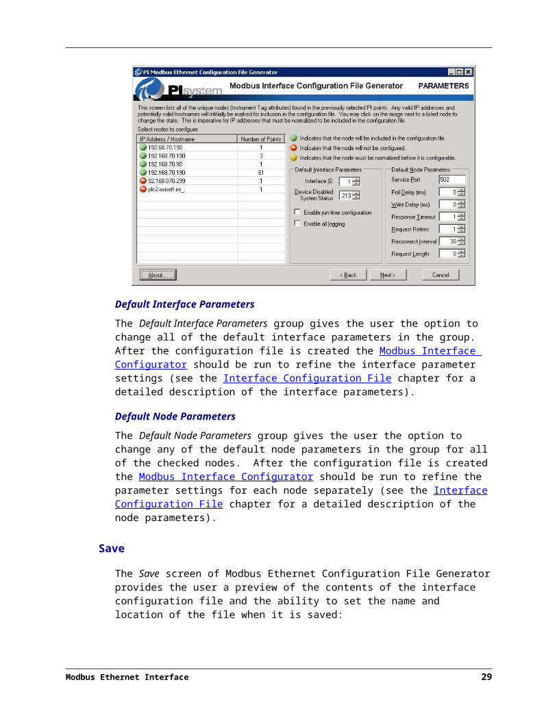
Default Parameters
The Parameters screen of Modbus Ethernet Configuration File Generator gives the user the opportunity to select all of the nodes (i.e. IP addresses and/or hostnames) to configure, and to set the default parameters for each node and the interface itself:
Select nodes to configureThe Select nodes to configure list will contain all of the unique nodes (i.e. IP addresses and hostnames) found in the PI Points previously selected to be used in creating the configuration file. Each node that is found to be valid for use in this interface will be automatically checked as noted by the checked symbol next to the node name (see the InstrumentTag section of the PI Point Configuration chapter on what constitutes a valid IP address or hostname). Otherwise the node will be displayed with an invalid or normalize symbol to indicate its status. The meaning and mutability of each symbol representing the state of a node is described below:
The checked symbol indicates that the node will be included in the generated configuration file. If this symbol is clicked the corresponding node will not be included in the configuration file and the symbol will changed to the invalid state.The normalize symbol indicates that the node will not be included in the configuration file because although it appears to be a valid IP address it does not meet the requirements for the interface. If the IP address can be normalized and this symbol is checked, the node will be converted into a valid IP address and the symbol will be changed to the checked state (e.g. IP address 192.168.072.180 is invalid because of a leading zero, so it can be normalized into 192.168.72.180). If the IP address cannot be normalized and this symbol is checked, the symbol will be changed to the invalid state (e.g. IP address 192.168.072.399 is invalid because of a leading zero and a value out of range, so even though it can be normalized into 192.168.72.399 it will still have an out of range value).
22

The invalid symbol indicates that the node will not be included in the configuration file. If this symbol is clicked and the corresponding node name is valid, the symbol will revert to the checked state. If this symbol is clicked and the corresponding node name is not valid, the symbol will not change and the following message box will be displayed:
The following figure demonstrates what the initial screen will look like after all of the nodes with a normalize symbol have been clicked:
Default Interface ParametersThe Default Interface Parameters group gives the user the option to change all of the default interface parameters in the group. After the configuration file is created the Modbus Interface Configurator should be run to refine the interface parameter settings (see the Interface Configuration File chapter for a detailed description of the interface parameters).
Default Node ParametersThe Default Node Parameters group gives the user the option to change any of the default node parameters in the group for all of the checked nodes. After the configuration file is created the Modbus Interface Configurator should be run to refine the parameter settings for each node separately (see the Interface Configuration File chapter for a detailed description of the node parameters).
Modbus Ethernet Interface 23

Upgrading From Previous Versions
Save
The Save screen of Modbus Ethernet Configuration File Generator provides the user a preview of the contents of the interface configuration file and the ability to set the name and location of the file when it is saved:
File NameThe File Name field must contain the entire path and file name of the interface configuration file to be generated. A user can either enter it directly into the File Name field or search for it by clicking the Browse button.
BrowseThe Browse button gives the user the option to search for the full path and name of the interface configuration file with the standard Microsoft Windows open file dialog. In this way a user can get the entire path and file name without having to enter it into the File Name field.
SaveTo generate the interface configuration file click the Save button. Once the file has been saved the Next button will be enabled and the text in the button will change to Finish.
PreviewThe Preview list shows the exact contents of what will be saved to the interface configuration file.
The following image shows how the Save screen of the Modbus Ethernet Configuration File Generator will appear after the interface configuration file has been saved:
24

At this point the interface configuration file has been generated and saved, and none of the previous operations can be repeated.
The Modbus Interface Configurator should now be run from the ICU after creating a new interface instance (see Configuring the Interface with PI ICU) using the newly created Interface Configuration File as input. This will allow the user to refine the parameter settings for both the interface and each Ethernet node in the interface configuration file.
Point Upgrade Requirements
In general, they are no changes required to PI Points configured for previous 3.x versions of the interface. The following describes the exception cases and what the user needs to do to update them for this release:
Square Root
The SquareRoot point attribute is used to specify operations to be applied to input and/or output values. In the previous version of the interface, the case in which the SquareRoot attribute has a value of 3 and the conversion factor attribute Convers has a value of 1 may not be working as documented. The documentation for the previous version stated the following:
For floating point input tags (i.e., type real, float16, float32) and for Location3 of 103, 104, 106, 703, 704, 706: Value = Value / Convers
In fact, in the case of SquareRoot = 3 and Convers = 1, no operation was being performed on the value if Location3 did not contain one of the codes listed (i.e. 103, 104, 106, 703, 704 or 706). So while it may have appeared that the value was being divided by 1, the value was not being altered at all. In addition, the documentation was inaccurate in that the calculation was different if Location3 did not contain one of the listed codes. In that case, in which Convers > 1, the actual calculation being performed was the following:
Modbus Ethernet Interface 25

Upgrading From Previous Versions
Value = ([(Value – InstZero) / Convers] * Span) + Zero
The above is the calculation that should be performed in all cases in which Convers is not 0 and one of the listed codes is not used and, in this release, is performed. The actual calculations used for all combinations of the square root and conversion factor attributes can be found in the SquareRoot section of this document.
Users upgrading to this version of the interface need to be aware that points in which the SquareRoot attribute has a value of 3 and the conversion factor attribute Convers has a value of 1 may have a different result than previously seen. If the result was unchanged when running the 3.x version of the interface then change the SquareRoot value of the point to 0 to continue getting the same result. Otherwise, review the calculations in the SquareRoot section of this document to determine the change required, if any, of the SquareRoot attribute.
Data Type Conversion
Some manufacturers use a single 32-bit register while the Modbus standard says there should be two contiguous 16-bit registers for IEEE 32-bit floating point numbers. This is the reason why previous versions of the interface would automatically convert data type 4 to data type 6 (see the Data Types section of the PI Point Configuration chapter). Unfortunately this is potentially dangerous with output points and this interface supports the multiple write Modbus function codes (which the previous versions did not), so the auto-conversion functionality has been removed.
While the previous versions of the interface would auto-convert data type 4 to data type 6 in cases in which the Modbus device did not support the data type, in reality both data types 4 and 5 can be problematic. For example, in previous versions if a point contained the value 403 in the Location3 attribute it would be automatically converted to 603.
Because this is potentially dangerous with output points, any point using data type 4 or data type 5 must be manually converted to data type 6 if the data type is not supported by the Modbus device. If it is not known if the data types 4 or 5 are supported on the device, the interface can be run with the previously configured points. If not supported the PI log will contain a message such as the following:Request expected 4 bytes but the response contained 2 bytes. Verify the location 3 value of your tags.
In this case, change the Location3 attribute from 4xx to 6xx or 5xx to 6xx as required. For example, 404 would become 604 and 503 would become 603.
In addition to the Data Types section of the PI Point Configuration chapter, floating point numbers are described in detail in Appendix C.
26
1. Update Instrument Tags
Finally, update the Instrument Tag attribute of all points used by the interface instance to be one of the host names defined. This can easily be accomplished by using the PI-TagConfigurator Add-In utility to Microsoft Excel. It is important to try to balance the use of the host names among the points so that the number of tag groups is relatively equal in number. This will optimize performance and is discussed in detail in Tag Optimization in Appendix F.
Modbus Ethernet Interface 27

Chapter 6. Digital States
For more information regarding Digital States, refer to the PI Server documentation.
Digital State SetsPI digital states are discrete values represented by strings. These strings are organized in PI as digital state sets. Each digital state set is a user-defined list of strings, enumerated from 0 to n to represent different values of discrete data. For more information about PI digital tags and editing digital state sets, see the PI Server manuals.
An interface point that contains discrete data can be stored in PI as a digital point. A digital point associates discrete data with a digital state set, as specified by the user.
System Digital State SetSimilar to digital state sets is the system digital state set. This set is used for all tags, regardless of type to indicate the state of a tag at a particular time. For example, if the interface receives bad data from an interface point, it writes the system digital state bad input to PI instead of a value. The system digital state set has many unused states that can be used by the interface and other PI clients. Digital States 193-320 are reserved for OSIsoft applications. The following digital states can be written to the tags of the Modbus Ethernet Interface.
Digital State Condition
Bad Input (255) If data conversion is configured for an input tag or output tag (see the SquareRoot point attribute) and if that data conversion cannot be mathematically evaluated, Bad Input is written to the PI Tag instead of the converted value. For example, if the data conversion is to take the square root of the incoming value, but the incoming value is negative, Bad Input will be written to the PI Tag.
Invalid Data (299) If the interface receives a floating point value that corresponds to “Not a Number” (NAN) or an infinite value, Invalid Data is written to the input tag.
Bad Output (237) When an output is triggered by writing a value to the output tag’s source tag and when the output to the PLC fails, Bad Output is written to the output tag. For example, an output will fail if the output tag is configured to write a value to a register that does not exist.
Unit Down (213) When an Ethernet node is disabled, Unit Down is written to all of the tags on the node.
Modbus Ethernet Interface 29

Chapter 7. PointSource
The PointSource is a unique, single or multi-character string that is used to identify the PI point as a point that belongs to a particular interface. For example, the string Boiler1 may be used to identify points that belong to the MyInt Interface. To implement this, the PointSource attribute would be set to Boiler1 for every PI point that is configured for the MyInt Interface. Then, if /ps=Boiler1 is used on the startup command-line of the MyInt Interface, the Interface will search the PI Point Database upon startup for every PI point that is configured with a PointSource of Boiler1. Before an interface loads a point, the interface usually performs further checks by examining additional PI point attributes to determine whether a particular point is valid for the interface. For additional information, see the /ps parameter. If the PI API version being used is prior to 1.6.x or the PI Server version is prior to 3.4.370.x, the PointSource is limited to a single character unless the SDK is being used.
Case-sensitivity for PointSource AttributeThe PointSource character that is supplied with the /ps command-line parameter is not case sensitive. That is, /ps=P and /ps=p are equivalent.
Reserved Point SourcesSeveral subsystems and applications that ship with PI are associated with default PointSource characters. The Totalizer Subsystem uses the PointSource character T, the Alarm Subsystem uses G and @, Random uses R, RampSoak uses 9, and the Performance Equations Subsystem uses C. Do not use these PointSource characters or change the default point source characters for these applications. Also, if a PointSource character is not explicitly defined when creating a PI point; the point is assigned a default PointSource character of Lab (PI 3). Therefore, it would be confusing to use Lab as the PointSource character for an interface.
Note: Do not use a point source character that is already associated with another interface program. However it is acceptable to use the same point source for multiple instances of an interface.
Modbus Ethernet Interface 31

Chapter 8. PI Point Configuration
The PI point is the basic building block for controlling data flow to and from the PI Server. A single point is configured for each measurement value that needs to be archived.
Point Attributes
Use the point attributes below to define the PI point configuration for the Interface, including specifically what data to transfer.
Tag
The Tag attribute (or tagname) is the name for a point. There is a one-to-one correspondence between the name of a point and the point itself. Because of this relationship, PI documentation uses the terms “tag” and “point” interchangeably.
Follow these rules for naming PI points:
The name must be unique on the PI Server.
The first character must be alphanumeric, the underscore (_), or the percent sign (%).
Control characters such as linefeeds or tabs are illegal.
The following characters also are illegal: * ’ ? ; { } [ ] | \ ` ' "
LengthDepending on the version of the PI API and the PI Server, this Interface supports tags whose length is at most 255 or 1023 characters. The following table indicates the maximum length of this attribute for all the different combinations of PI API and PI Server versions.
PI API PI Server Maximum Length
1.6.0.2 or higher 3.4.370.x or higher 1023
1.6.0.2 or higher Below 3.4.370.x 255
Below 1.6.0.2 3.4.370.x or higher 255
Below 1.6.0.2 Below 3.4.370.x 255
PointSource
The PointSource attribute contains a unique, single or multi-character string that is used to identify the PI point as a point that belongs to a particular interface. For additional information, see the /ps command-line parameter and the “PointSource” section.
Modbus Ethernet Interface 33

PointType
Typically, device point types do not need to correspond to PI point types. For example, integer values from a device can be sent to floating point or digital PI tags. Similarly, a floating-point value from the device can be sent to integer or digital PI tags, although the values will be truncated.
Float16, float32, float 64, int16, int32, digital, and string point types are supported. For more information on the individual PointTypes, see PI Server manuals.
Location1
Location1 indicates to which copy of the Interface the point belongs. The value of this attribute must match the /id command-line parameter.
Location2
Location2 identifies the destination PLC node. The node is identified with a number between 1 and 256, inclusive. Only the destination node number is specified in Location2.
Note that some PLCs use an octal or hexadecimal representation for the node ID. The corresponding integer value should be placed in Location2.
Location3
Location3 specifies the Data Type and the Function Code of the PI Point. The Data Type is an integer value specifying whether the register values in a PLC are interpreted as integers, floats, binary coded decimals, etc. The Function Code is an integer value that refers to either a corresponding Modbus function code or a custom non-standard function code not supported by the Modbus standards. Since Location3 consists of two different values the following formula is used to compute the actual value of the Location3 attribute:
Location3 = (Data Type * 100) + Function Code
Example: For function code 4 (read input register) and data type 2 (4-digit BCD), Location3 would be 204.
The rest of this section describes all of the data types and function codes in detail, and which combinations of the two values are a valid Location3 attribute.
Modbus Ethernet Interface 34

Data TypesThis interface supports a number of integer, floating point and binary coded decimal data types which can be used with one or more of the supported function codes for reading and writing coils, discrete inputs and registers (the Validation topic further down in this section describes which function codes are valid with each data type). The table below describes each of the data types supported by this interface:
Data Type Comments1 16-bit Integer
For real PI points, the 16-bit register is interpreted as a signed integer (-32768 to 32767). For integer PI points, the 16-bit register is interpreted as an unsigned integer (0 to 65535). Additional notes: Int16 points in PI 3 can take values between 0 and 32767. As mentioned above, however, the 16-bit register value is interpreted as an unsigned integer between 0 and 65535 for integer type PI points and data type 1. If a value greater than 32767 is sent to an int16 in PI 3, OVER RANGE will be written to the point instead.Float16 points in PI 3 can take values between 0 and 32767. As mentioned above, however, the 16-bit register value is interpreted as a signed integer between –32768 and 32767 for a real type PI point and data type 1. If a value that is less than 0 is sent to a float16 point in PI 3, UNDER RANGE will be written to the point instead.The 16-bit register value for data type 1 is interpreted as an unsigned integer between 0 and 65535 for int32 points in PI 3. There are no problems with UNDER RANGE or OVER RANGE for int32 points in PI 3.The 16-bit register value for data type 1 is interpreted as an unsigned integer between –32768 and 32767 for float32 points in PI 3. There are no problems with UNDER RANGE or OVER RANGE for float32 points in PI 3.
2 4-Digit Binary-Coded Decimal (BCD)For input points, the 16-bit register is converted from a BCD to an integer. For output points, the value of the PI point is converted from an integer to a BCD before it is written to the register. BCD representation of integer values between 0 and 9999 are supported. If a negative value is written to a source tag of an output point, UNDER RANGE is written to the output point. If a value greater than 9999 is written to the source tag of an output point, then OVER RANGE is written to the output point.Example:The integer 1925 is represented as a BCD by the hexadecimal number 0x1925 (or by the integer 6437). Each byte of the BCD represents one digit of the integer.
3 Log Base 2The range of values that can be written to an output point are between 0 and 15, inclusive. There is no range checking for input points.Example:If a value of 5 is written to an output point, then 25 or 32 is written to the register. If 32 is read from a register into an input point, it is converted to a value of 5 before it is stored in the input point.
4 Floating Point, 32 bit (Appendix C has more information on floating points)Values stored in the PLC are interpreted as a standard IEEE 4-byte float. For PI 3, the PI point should be configured as a float32.A PLC that understands data type 4, interprets function code 3, 4, and 6 in a nonstandard fashion. The PLC maps a single register to two different registers so that the single register can effectively store four bytes of information instead of two.
Modbus Ethernet Interface 35
PI Point Configuration
Data Type Comments5 Floating Point (Appendix C has more information on floating points)
Values stored in the PLC are interpreted as a standard IEEE 4-byte float. For PI 3, the PI point should be configured as a float32.A PLC that understands data type 5, interprets function code 3, 4, and 6 in a nonstandard fashion. When data from register 5 is requested, for example, data from both registers 5 and 6 is returned.
6 Floating Point (Appendix C has more information on floating points)Values stored in the PLC are interpreted as a standard IEEE 4-byte float. For PI 3, the PI point should be configured as a float32.This is the most common data type for floating points. Try this data type first. If this data type does not work, try adding the /swap6 parameter to the command line of the interface before trying a different data type.
7 4-Byte Integer (Appendix C has more information on 4-byte integers).To avoid problems with OVER RANGE and UNDER RANGE, the PI Point should be configured as an int32 or a float32 in PI 3. See data type 1 for further information regarding the limitations of the different PI Point types.
8 Siemens Floating point (see Appendix C for more information).Values stored in the PLC are interpreted as Siemens floating point format. This format is only required in very specialized cases. For PI 3, the PI point should be configured as a float32.
9 Non-standard 4-Byte Integer (Appendix C has more information on 4-byte integers).To avoid problems with OVER RANGE and UNDER RANGE, the PI Point should be configured as an int32 or a float32 in PI 3. See data type 1 for further information regarding the limitations of the different PI Point types.
11 16 bit Unsigned Integer Data type 11 is identical to data type 1 except that the 16-bit register is interpreted as an unsigned integer (0 to 65535) for integer PI Points.
12 16-Digit Binary-Coded Decimal (BCD) (supported for input tags only)Four consecutive 2-byte registers are converted from a BCD to an integer. It is recommended that the integer be stored in a float64 tag to maximize the significant digits. Note, however, that a float64 tag only has 13 digits of precision whereas a 16-digit BCD has 16-digits of precision.
13 64 bit (8-Byte) Signed Integer (supported for input tags only)It is required that the integer be stored in a float64 tag to maximize the significant digits. Note, however, that a float64 tag only has 13 digits of precision.When data type 13 is used, the ModbusE interface combines the values from 4-consecuative 2-byte registers to come up with a 8-byte signed integer.
14 Double precision Enron floating point. This is the double precision counterpart to data type 4.
15 64 bit (8-Byte) Unsigned Integer (supported for input tags only)It is required that the integer be stored in a float64 tag to maximize the significant digits. Note, however, that a float64 tag only has 13 digits of precision.When data type 15 is used, the ModbusE interface combines the values from 4-consecuative 2-byte registers to come up with a 8-byte signed integer.
16 Double precision floating pointValues stored in the PLC are interpreted as a standard IEEE 8-byte double precision floating point values. However, the value that is actually stored in PI will be a single precision floating point value even if the PI point type is float64. For PI 3, the PI point should be configured as a float32 or float64.When this data type is used, the ModbusE interface expects to read the double from 4 consecutive 2-byte registers on the PLC. Data type 16 is the 8-byte equivalent of data type 6, which is used for 4-byte IEEE floats.
36

Data Type Comments101 to 199 Data types 101 to 199 are reserved for string data. Data type 101 is used to
read 1-byte strings; data type 102 is used to read 2-byte strings; and so on. For example, to read a 5-byte string from an input register (Modbus function code 4) one would set the Location3 attribute to 10504 because Location3 is equal to (Data Type * 100) + Function Code.
Byte SwappingBecause the manner in which data is stored in PLCs may vary not only from manufacturer to manufacturer but even from model to model, it may be necessary for the user to specify the byte order for data types larger than 16-bits. This can be achieved by “swapping” the bytes of data for some data types. The interface allows the user to set byte swapping for the required data types for all PI Points with the same Ethernet node (see Interface Configuration File ) and/or for individual PI Points (see Extended Descriptor). The tables below list the swapping types and data types for which byte swapping is supported:
Swapping Type Byte Order from PLC After Swapping by InterfaceNo Swapping [AB] [CD] [AB] [CD]
Byte Swapping [BA] [DC] [AB] [CD]
Word Swapping [CD] [AB] [AB] [CD]
Both Swapping [DC] [BA] [AB] [CD]
Note: Each letter represents a byte. Two letters enclosed in square brackets represents a 16-bit register.
Data Type Description Swapping
Not Enabled Enabled4 Floating Point Byte Swapping Both Swapping
6 Floating Point Both Swapping Byte Swapping
7 4-Byte Integer Both Swapping Byte Swapping
13 64 bit (8-Byte) Signed Integer Both Swapping Byte Swapping
15 64 bit (8-Byte) Unsigned Integer
Both Swapping Byte Swapping
16 Double precision floating point
Both Swapping No Swapping
101 to 199 Strings No Swapping Byte Swapping
Modbus Ethernet Interface 37

PI Point Configuration
Function CodesThis interface supports all of the standard Modbus function codes for reading coils, discrete inputs and registers. It also supports the function codes to write to a single coil or register and to write to multiple contiguous coils and registers. In addition, it supports the custom function code 65 to read HTMUX floating point values. The table below describes each of the function codes supported by this interface:
Function Code Description1 Read Coil Status to input tag.
2 Read Input Status to input tag.
3 Read Holding Register to input tag.
4 Read Input Register to input tag.
5 Write Single Coil using output tag.
6 Write Single Holding Register using output tag.
Note: The interface will convert function code 6 to 16 when it is necessary to send floating point numbers to two consecutive registers.
15 Write Multiple Coils using output tags.
16 Write Multiple Registers using output tags.
65 Read floating point value from 4-byte register. There is no data type associated with function code 65 because the interpretation of the register value is determined by the function code itself. Hence, Location3 should just be assigned a value of 65 when this function type is required. See Appendix C for more information on function code 65.
ValidationThe table below lists all of the supported data types and the function codes that are valid to use with each data type:
Data Type Description Supported Function Codes
1 16-bit Integer All function codes
2 4-Digit Binary-Coded Decimal (BCD) Function codes 3, 4, 6 and 16
3 Log Base 2 Function codes 3, 4, 6 and 16
4 Floating Point Function codes 3, 4, 6 and 16
5 Floating Point Function codes 3, 4, 6 and 16
6 Floating Point Function codes 3, 4, 6 and 16
7 4-Byte Integer Function codes 3, 4, 6 and 16
8 Siemens Floating point Function codes 3, 4, 6 and 16
9 Non-standard 4-Byte Integer Function codes 3 and 4
11 16-bit Unsigned Integer All function codes
12 16-Digit Binary-Coded Decimal (BCD) Function codes 3 and 4
13 64 bit (8-Byte) Signed Integer Function codes 3 and 4
14 Double precision Enron floating point Function codes 3 and 4
15 64 bit (8-Byte) Unsigned Integer Function codes 3 and 4
38

Data Type Description Supported Function Codes16 Double precision floating point Function codes 3 and 4
101 to 199 Strings Function codes 3 and 4
Location4
Scan-based InputsFor interfaces that support scan-based collection of data, Location4 defines the scan class for the PI point. The scan class determines the frequency at which input points are scanned for new values. For more information, see the description of the /f parameter in the Startup Command File section.
Trigger-based Inputs, Unsolicited Inputs, and Output PointsLocation 4 should be set to zero for these points.
Location5
Location5 is used to specify an offset (one relative) to a particular coil, input status, holding register, or input register. It is important to realize that Location5 is used to specify an offset, not an absolute address. For example, say that the value from holding register 40083 is to be read and that the first holding register begins at 40001. One would specify 83 in Location5, not 40083. The correct absolute address, 40083, will be accessed as long as one specifies a function code of 3 in Location3 (for example, Location3=103).
For Modicon Hardware: function codes 1 and 5 begin at coil 1, function code 2 begins at input 1001 or 10001 or 100001, function codes 3 and 6 begin at holding register 4001 or 40001 or 400001, and function code 4 begins at input register 3001 or 30001 or 300001. For Honeywell Hardware: I/O locations range from 0 to 4095 and registers locations start at 4096.
InstrumentTag
LengthDepending on the version of the PI API and the PI Server, this Interface supports an InstrumentTag attribute whose length is at most 32 or 1023 characters. The following table indicates the maximum length of this attribute for all the different combinations of PI API and PI Server versions.
PI API PI Server Maximum Length
1.6.0.2 or higher 3.4.370.x or higher 1023
1.6.0.2 or higher Below 3.4.370.x 32
Below 1.6.0.2 3.4.370.x or higher 32
Below 1.6.0.2 Below 3.4.370.x 32
If the PI Server version is earlier than 3.4.370.x or the PI API version is earlier than 1.6.0.2, and you want to use a maximum InstrumentTag length of 1023, you need to enable the PI SDK. See Appendix B for information.
Modbus Ethernet Interface 39

PI Point Configuration
The InstrumentTag attribute specifies the Ethernet communications node for the PI Point. It must be a valid IP address or hostname. For example, plc3.osisoft.int would specify that the PI Point will be associated with the configured node plc3.osisoft.int:502.
The interface will validate that the InstrumentTag attribute specifies a valid IP address or hostname when loading the PI Point and that is an IP address or hostname that has previously been configured. The rules for validation are described in the following sections.
IP AddressThe supported IP address (Internet Protocol address) is what is known as Internet Protocol Version 4 or IPv4. It is represented in dot-decimal notation (four parts, each one a number ranging from 0 to 255, separated by dots). The following are the requirements of a valid IP address for this interface:
It must be in the form xxx.xxx.xxx.xxx in which the four parts are separated by periods (i.e. dots).
Each part xxx must contain only decimal digit characters '0' through '9'.
Each part xxx must represent a number from 0 to 255.
No part with more than 1 digit character can have a leading zero character. Although a valid IP address can have a leading zero in a part, networks will treat parts with leading zeros as either octal numbers or as being invalid (if any of the other digits are 8 or 9). To ensure that all PI Points for a given address use the same format, the interface will disallow IP addresses with octal parts.
HostnameThe supported hostname consists of a series of one or more labels concatenated with dots (just as domain names are). It is represented by either a single label or multiple labels in dot-decimal notation (two or more labels, each one separated by dots). The following are the requirements of a valid hostname for this interface:
It must be in the form xxx or xxx.xxx.[…].xxx in which each label is separated by periods (i.e. dots).
Each label xxx must contain only ASCII characters 'a' through 'z' (in a case-insensitive manner), the digit characters '0' through '9', the hyphen (‐) character and the underscore (_) character.
Each label xxx cannot begin or end with either the hyphen (‐) character or the underscore (_) character.
Each label xxx must be between 1 and 63 characters in length.
The entire hostname may contain of no more than 8 labels.
The entire hostname (including the delimiting dots) can be no more than 255 characters in length.
NOTE: The use of the underscore character is non-standard but is allowed because it is often used in hostnames in Microsoft Windows systems.
40

ExDesc
LengthDepending on the version of the PI API and the PI Server, this Interface supports an ExDesc attribute whose length is at most 80 or 1023 characters. The following table indicates the maximum length of this attribute for all the different combinations of PI API and PI Server versions.
PI API PI Server Maximum Length
1.6.0.2 or higher 3.4.370.x or higher 1023
1.6.0.2 or higher Below 3.4.370.x 80
Below 1.6.0.2 3.4.370.x or higher 80
Below 1.6.0.2 Below 3.4.370.x 80
If the PI Server version is earlier than 3.4.370.x or the PI API version is earlier than 1.6.0.2, and you want to use a maximum ExDesc length of 1023, you need to enable the PI SDK. See Appendix B for information.
The extended descriptor can be used to specify additional and optional attributes such as a trigger tag (for input tags only), a bit mask (for input tags only), a custom data type manipulator, an instrument zero value for a PLC and byte swapping.
Use the following syntax for the extended descriptor:event=’triggertag’,b=bitmask,c=cdtm,z=InstZero,solitary,swap
For example:event=’sinusoid’,b=01,c=3,z=10,swap
The trigger tag, bitmask, custom data type manipulator, instrument zero and byte swapping descriptors must be separated by comas. The following subsections describe the format and usage of each of the extended descriptors:
Bit MaskThe bit mask (b) descriptor is used to define a bitmask used to extract bits from a register. The format of the bitmask is:
b=uuvvwwxxyyzz
where uu, vv, ww, yy, and zz each refer to a single bit. A leading zero is required if the referenced bit is less than 10. The low-order bit is 01 and high-order bit is either 16 or 32. Up to 16 bits can be referenced for a 16-bit word (data types 1 and 11) and up to 32 bits can be reference for a 32-bit word (data type 7 and 9).
The bitmask 0307120802 will map the second bit of the original word to the first bit of the new word, the eighth bit to the second bit, the twelfth bit to the third bit, etc. The high-order bits of the new word are padded with zeros if they are not specified.
Say that a single 16-bit PLC register holds the state of four different thermocouples. The first 4 bits correspond to the first thermocouple; the second 4 bits correspond to the second thermocouple, etc. Four different input tags with four different bit masks could be used to read thermocouple states. The first input tag would use a bit mask of 04030201 to read the state of the first thermocouple; the second input tag would use a bit mask of 08070605 to read the state of the second thermocouple, and so on. If the sixteen bit word from the PLC was 0000 0000 0101 0111 or decimal 87, then the first thermocouple state would be interpreted as
Modbus Ethernet Interface 41

PI Point Configuration
binary 0111 or decimal 7, the second thermocouple state would be interpreted as 0101 or decimal 5, etc.
For 4-byte integer values (data types 7 and 9), the bytes for these tags are frequently swapped. The bytes can be swapped with the following bitmask:b=1615141312111009080706050403020132313029282726252423222120191817
The bit mask can be used only with input tags of data type 1, 7, 9 or 11. The bit mask does not apply to output tags.
Custom Data Type ManipulatorThe custom data type manipulator (c) descriptor is described in the table below. The default value of custom data type manipulator is zero if it is not defined in the extended descriptor:
Custom Data Type Manipulator
Description
0 No custom data type defined. This is the default.
1 GE EPM 9650/9800 Meter (Type F3 Timestamp). Length: 4 Registers (8 bytes).Input Tag: Must use Location3=10803 and PtType=stringEach byte contains a binary number representing up to two digitsin a part of date and time.
2 GE EPM 9650/9800 Meter (Type F21 Year). Length: 1 Registers (2 bytes).Must use Location3=103 for PtType=int32Each byte contains a binary number representing up to two digitsin a part of year.
3 GE EPM 9650/9800 Meter (Type F60 Energy Counter). Length: 2 Registers (4 bytes).Must use Location3=703Must use PtType=int32 or PtType=float32Each pair of registers represents an Energy Counter in primary. Each register contains a value from 0 to 9,999 (0x00000 - 0x0270F), representing 4 digits of an Energy Counter. The first register is in units of 10’s of MegaWatthour or Mega VARhour. The second register is in units of kilo Watthour or kilo VARhour. Combined, the pair of registers report up to 100 GWh primary of energy.
4 GE EPM 9650/9800 Meter (Type F61 12-bit RTU Frequency). Length: 1 Registers (2 bytes).Must use Location3=103Must use PtType=int32 or PtType=float32This register contains a 16-bit unsigned integer. The 16-bit integer has been constrained to the bounds of an unsigned 12-bit integer, 4095 to 0. The Frequency represented by this register is offset by 45 Hz.
Instrument ZeroThe instrument zero (z) descriptor is used to specify the instrument zero of the PLC. The instrument zero value is utilized in calculations that are used to specify operations to be applied to input and/or output values as described in the SquareRoot section.
SolitaryThe optional solitary output (solitary) descriptor is used to specify an output tag that is not to be optimized (i.e. grouped) with any other output tags. The solitary descriptor is utilized to
42

ensure that an output tag will be updated when its associated source tag is updated without being dependent on the updates to all of the source tags associated with the output tags in a group of contiguous tags. Since the use of the solitary descriptor may break up what could be a single tag group of optimized output tags (see Tag Configuration Optimization in Appendix F), it benefits the user to use this descriptor with care.
SwapThe swap descriptor is used only in conjunction with points in which the data type supports byte swapping (see Byte Swapping in the Location3 section). Some PLCs store floating points with the high and low bytes swapped from the default order that the ModbusE interface is expecting (see Appendix C). If this is the case for only a given PI Point, the swap descriptor will need to be specified.
Performance Points For UniInt-based interfaces, the extended descriptor is checked for the string “PERFORMANCE_POINT”. If this character string is found, UniInt treats this point as a performance point. See the section called Scan Class Performance Points.
Trigger-based Inputs For trigger-based input points, a separate trigger point must be configured. An input point is associated with a trigger point by entering a case-insensitive string in the extended descriptor (ExDesc) PI point attribute of the input point of the form:keyword=trigger_tag_name
where keyword is replaced by “event” or “trig” and trigger_tag_name is replaced by the name of the trigger point. There should be no spaces in the string. UniInt automatically assumes that an input point is trigger-based instead of scan-based when the keyword=trigger_tag_name string is found in the extended descriptor attribute.
An input is triggered when a new value is sent to the Snapshot of the trigger point. The new value does not need to be different than the previous Snapshot value to trigger an input, but the timestamp of the new value must be greater than (more recent than) or equal to the timestamp of the previous value. This is different than the trigger mechanism for output points. For output points, the timestamp of the trigger value must be greater than (not greater than or equal to) the timestamp of the previous value.
Conditions can be placed on trigger events. Event conditions are specified in the extended descriptor as follows:Event='trigger_tag_name' event_condition
The trigger tag name must be in single quotes. For example,Event='Sinusoid' Anychange
will trigger on any event to the PI Tag sinusoid as long as the next event is different than the last event. The initial event is read from the snapshot.
Modbus Ethernet Interface 43

PI Point Configuration
The keywords in the following table can be used to specify trigger conditions.
Event Condition
Description
Anychange Trigger on any change as long as the value of the current event is different than the value of the previous event. System digital states also trigger events. For example, an event will be triggered on a value change from 0 to “Bad Input,” and an event will be triggered on a value change from “Bad Input” to 0.
Increment Trigger on any increase in value. System digital states do not trigger events. For example, an event will be triggered on a value change from 0 to 1, but an event will not be triggered on a value change from “Pt Created” to 0. Likewise, an event will not be triggered on a value change from 0 to “Bad Input.”
Decrement Trigger on any decrease in value. System digital states do not trigger events. For example, an event will be triggered on a value change from 1 to 0, but an event will not be triggered on a value change from “Pt Created” to 0. Likewise, an event will not be triggered on a value change from 0 to “Bad Input.”
Nonzero Trigger on any non-zero value. Events are not triggered when a system digital state is written to the trigger tag. For example, an event is triggered on a value change from “Pt Created” to 1, but an event is not triggered on a value change from 1 to “Bad Input.”
Scan
By default, the Scan attribute has a value of 1, which means that scanning is turned on for the point. Setting the scan attribute to 0 turns scanning off. If the scan attribute is 0 when the Interface starts, a message is written to the pipc.log and the tag is not loaded by the Interface. There is one exception to the previous statement.
If any PI point is removed from the Interface while the Interface is running (including setting the scan attribute to 0), SCAN OFF will be written to the PI point regardless of the value of the Scan attribute. Two examples of actions that would remove a PI point from an interface are to change the point source or set the scan attribute to 0. If an interface specific attribute is changed that causes the tag to be rejected by the Interface, SCAN OFF will be written to the PI point.
SourceTag
A SourceTag is used in conjunction with an output tag. An output tag is a tag for which the function code has been set to 5, 6, 15 or 16 in Location3. See section “Output Tag Configuration” for essential details on output tags and SourceTags. The SourceTag attribute is optional.
Zero
The Zero attribute ideally represents the lowest possible value for an input or an output tag. The Zero attribute is not the same as the instrument zero (InstZero), which is described in the extended descriptor. Do not assign a value to the Zero attribute for PI Points of type digital. Changing the Zero attribute for a digital tag can adversely affect the configuration of the PI Point. The Zero attribute is optional and has a default value of 0.
The interface will not throw out or alter values that are less than the Zero PI Point attribute. The interface only uses the Zero attribute to perform the conversions that are described under the SquareRoot PI Point attribute.
44

Span
The Zero attribute + the Span attribute ideally represent the maximum possible value for an input or an output tag. Do not assign a value to the Span attribute for PI Points of type digital. Changing the Span attribute for a digital tag can adversely affect the configuration of the PI Point. The Span attribute is optional and has a default value of 100.
The interface will not throw out or alter values that are outside of the range specified by the Zero and Span. The interface only uses the Zero and Span attributes to perform the conversions that are described under the SquareRoot PI Point attribute.
Shutdown
The Shutdown attribute is 1 (true) by default. The default behavior of the PI Shutdown subsystem is to write the SHUTDOWN digital state to all PI points when PI is started. The timestamp that is used for the SHUTDOWN events is retrieved from a file that is updated by the Snapshot Subsystem. The timestamp is usually updated every 15 minutes, which means that the timestamp for the SHUTDOWN events will be accurate to within 15 minutes in the event of a power failure. For additional information on shutdown events, refer to PI Server manuals.
Note: The SHUTDOWN events that are written by the PI Shutdown subsystem are independent of the SHUTDOWN events that are written by the Interface when the /stopstat=Shutdown command-line parameter is specified.
SHUTDOWN events can be disabled from being written to PI when PI is restarted by setting the Shutdown attribute to 0 for each point. Alternatively, the default behavior of the PI Shutdown Subsystem can be changed to write SHUTDOWN events only for PI points that have their Shutdown attribute set to 0. To change the default behavior, edit the \PI\dat\Shutdown.dat file, as discussed in PI Server manuals.
Bufserv and PIBufssIt is undesirable to write shutdown events when buffering is being used. Bufserv and PIBufss are utility programs that provide the capability to store and forward events to a PI Server, allowing continuous data collection when the Server is down for maintenance, upgrades, backups, and unexpected failures. That is, when PI is shutdown, Bufserv or PIBufss will continue to collect data for the Interface, making it undesirable to write SHUTDOWN events to the PI points for this Interface. Disabling Shutdown is recommended when sending data to a Highly Available PI Server Collective. Refer to the Bufserv or PIBufss manuals for additional information.
Convers
This attribute specifies the conversion factor. The use of the conversion factor is described under the SquareRoot PI Point attribute. The default value is 1.
SquareRoot
The SquareRoot field is used to specify operations to be applied to input and/or output values and has a default value of 0. OPERATIONS ARE NEVER APPLIED FOR DIGITAL TAGS.
Modbus Ethernet Interface 45

PI Point Configuration
Several parameters are used for the operations, including:
Parameter Usage
Convers The conversion factor PI Point Attribute.
InstZero The instrument zero of the PLC, which is defined in the extended descriptor.
Zero The Zero PI Point Attribute.
Span The Span PI Point Attribute.
Value This parameter represents a value from a PLC that is sent to an input tag or a value that is sent to a PLC from an output tag (or SourceTag). The conversions below are performed on Value.
Example: An input tag is used to read the temperature of a beaker of water. The water temperature range is between 0 oC and 100 oC. The range of values from the PLC is between -10000 and +10000, where -10000 corresponds to 0 oC and 10000 corresponds to 100 oC. To properly convert the value from the PLC to a temperature in oC, use the following settings: InstZero=-10000, Convers=20000, Zero=0, Span=100, SquareRoot=0.
The conversion that is applied depends upon the value of the SquareRoot and Convers parameters:
Conditions OperationSquareRoot=0Convers0 andConvers1
Input tags:Value = ([(Value – InstZero) / Convers ] * Span) + Zero
Output tags:Value = ([(Value - Zero) / Span] * Convers) + InstZero
SquareRoot=0Convers=0 orConvers=1
No operation performed on input or output tags:Value = Value
SquareRoot=1Convers0 andConvers1
Two-step operation for input tags:Value = (Value) 0.5
Value = ([(Value – InstZero) / Convers ] * Span) + ZeroTwo-step operation for output tags:
Value = (Value) 0.5
Value = ([(Value - Zero) / Span] * Convers) + InstZeroSquareRoot=1Convers=0 orConvers=1
Input tags and output tags:Value = (Value) 0.5
SquareRoot=2Convers0 andConvers1
Two-step operation for input tags:Value = (Value) 2
Value = ([(Value – InstZero) / Convers ] * Span) + ZeroTwo-step operation for output tags:
Value = (Value) 2
Value = ([(Value - Zero) / Span] * Convers) + InstZeroSquareRoot=2Convers=0 orConvers=1 orpoint type is digital
Input tags and output tags:Value = (Value) 2
46

Conditions OperationSquareRoot=3Convers0
For floating point (i.e., type float16, float32) input tags: For Location3 of 103, 104, 703, 704, 903, 904:
Value = Value / Convers Otherwise:
Value = ([(Value – InstZero) / Convers ] * Span) + ZeroFor floating point (i.e., type float16, float32) output tags: For Location3 of 106, 116, 706, 716, 906, 916, 1106, 1116:
Value = Value * Convers Otherwise:
Value = ([(Value - Zero) / Span] * Convers) + InstZeroFor integer (i.e. type int16, int32) input tags:
Value = ([(Value – InstZero) / Convers ] * Span) + ZeroFor integer (i.e. type int16, int32) output tags:
Value = ([(Value - Zero) / Span] * Convers) + InstZeroSquareRoot=3Convers=0
No operation performed on input or output tags:Value = Value
SquareRoot=4 Same as SquareRoot=0SquareRoot=5Convers=0
Input tags:Value = (Value / Convers) – InstZero
Output tags:Value = (Value + InstZero) * Convers
SquareRoot=5Convers=0
No operation performed on input or output tags:Value = Value
SquareRoot=6Convers=0
Input tags:Value = (Value - InstZero) / Convers
Output tags:Value = (Value * Convers) + InstZero
SquareRoot=6Convers=0
No operation performed on input or output tags:Value = Value
Input Tag Configuration
Input tags are used to receive data from PLC nodes. A tag is an input tag if function code 1, 2, 3, 4, or 65 is specified in Location3 (Location3 = (Data Type * 100) + Function Code). For example, if location3 is 603, then the PI Point is an input tag.
If no "triggertag" is specified in the extended descriptor (ExDesc) attribute of the input tag, then the associated PLC will be scanned at a given frequency. The frequency is specified using the Location4 point attribute in conjunction with the /f parameter on the startup command line of the interface. The input tag is said to be scan-based in this case.
If a "triggertag" is specified in the extended descriptor (ExDesc) attribute of the input tag, then the associated PLC will be scanned only when a new value is sent to the snapshot of the triggertag. The input tag is said to be event-based in this case.
Whenever a complete response fails to be received from a PLC before a configurable timeout period has expired (see the /to=x startup command-line parameter), IO TIMEOUT will be written to the affected tags. Normally, increasing the timeout period does not help because the problem is usually related to incorrect hardware configuration. For example, if the PLC node in the Location2 point attribute is invalid, then a response may not be received by the interface.
If a communication error occurs that is not associated with a timeout, then BAD INPUT will be written to the affected tags instead of IO TIMEOUT. For example, BAD INPUT will be written to the input tags if any of the PLC exception responses that are listed in Appendix E occur for serial-based Modbus communication.
Modbus Ethernet Interface 47

PI Point Configuration
If the Scan field of an input tag is turned off while the interface is running, SCAN OFF (digital state 238) will be written to the input tag.
There are several other digital states that can also be written to input tags. These must be handled on a case-by-case basis.
Optimization
Due to the nature of the Modbus application protocol, a single request may result in a response with data for up to 2,000 tags. To optimize performance the interface will place tags into groups based on common key attributes so that the maximum number of input tags can be updated by a single response. The methodology for optimized input tag configuration can be found in Appendix F.
Output Tag Configuration
Output tags are used to send commands to a PLC node. A tag is an output tag if function code 5 or 6 is specified in Location3. Commands are sent to the PLC only upon an event. An event is triggered in one of two ways, depending upon the configuration of the output tag.
Configuration 1 (recommended): In this configuration, a command is written to the PLC when an event is detected for a SourceTag. A SourceTag is associated with an output tag through the output tag’s SourceTag field. The value of the SourceTag is written to the output tag if the command is successful. The PointType of the output tag and SourceTag do not need to be the same.
Configuration 2: In this configuration, a command is written to the PLC when an event is detected for the output tag itself. This configuration is enabled if no SourceTag is defined in the output tag’s SourceTag field.
When do "events" occur? An event occurs whenever a value reaches the snapshot of the SourceTag (configuration 1) or the output tag (configuration 2). The actual value of the snapshot does not need to change to trigger an event
What commands are sent to the PLC? The command is determined by the Location3 value of the output tag. For example, if Location3 is set to 105, then the command to the PLC will be to force a single coil either on or off. The coil is turned on if the trigger value that is sent to the SourceTag (configuration 1) or to the output tag (configuration 2) is greater than zero. The coil is turned off if the trigger value that is sent to the SourceTag (configuration 1) or output tag (configuration 2) is equal to zero. If Location3 is set to 106, then the command is to modify the contents of a holding register. The value that is sent to the holding register is determined by the value that is sent to the SourceTag (configuration 1) or output tag (configuration 2).
Digital state messages sent to the output tag. Informative digital state messages are sent to the output tag only for configuration 1, which is why configuration 1 is recommended. If there is trouble sending a command to the PLC, then an appropriate digital state is written to the output tag. The use of output tags is demonstrated below by examples.
Example 1
Configure an output tag and a source tag to force coil number 131 on or off (function code 5). The source tag should be configured so that the on/off status of the coil can be changed using
48

manual inputs. Assume that the interface number is 2, that the PLC node is 77, and that the PointSource for the interface is M.
Modbus Ethernet Interface 49

PI Point Configuration
Solution
Part 1, Configure the Output Tag:Call the output tag c131out. The output tag is used to specify the interface number (Location1), the PLC node (Location2), the data type and a function code (Location3), and the coil number to be changed (Location5). The Location4 parameter is ignored when the SourceTag field is specified. The PointSource for the output tag corresponds to the ModbusE interface, which is M in this example. The PointType of the output tag and the SourceTag are configured to be the same. The CompDev and ExcDev are set to zero for the output tag because the source tag is to be configured as a manual input point (lab data) for which the CompDev and ExcDev should also be zero. Generally, compression and exception should be turned off for manually entered points. The zero and span are set to correspond to the source tag. A TypicalValue and a SquareRoot code are configured below. We can specify any value for these parameters (and other parameters) since no restrictions were posed in the problem statement. For a PI3 home node, the user may additionally wish to set Step=1.
Output Tag Configuration - Example 1
PI3 Home Node
Tag c131out
PointType int16
Zero 0
Span 1
TypicalValue 1
PointSource M
Location1 2
Location2 77
Location3 105
Location5 131
SquareRoot 0
SourceTag c131src
CompDev 0
ExcDev 0
Part 2, Configure the Source Tag: No restrictions are placed on the PointSource, but Pointsource Lab is appropriate for the manual inputs required in this example. The CompDev and ExcDev are set to zero, which is appropriate for manually entered points. Since the SourceTag does not receive values from an interface (in this example) the Location parameters are ignored if specified. When the source tag is set to 0, coil 131 will be turned off. When the source tag is set to any positive value, coil 131 will be turned on. The zero is set to 0 and the Span is set to 1, which is the minimum range required to turn the coil off and on.
Source Tag Configuration - Example 1
PI3 Home node
Tag c131src
PointType int16
50

Source Tag Configuration - Example 1
Zero 0
Span 1
TypicalValue 1
PointSource Lab
CompDev 0
ExcDev 0
Example 2
Configure an output tag to force coil number 131 on or off (function code 5). Do not configure a source tag. Since no source tag is to be used, the values for the output tag must be entered manually. Assume that the interface number is 2, that the PLC node is 77, and that the PointSource for the interface is M.
Solution:The configuration is the same as in example 1 except that no source tag is specified in the configuration. When the output tag is set to 0, coil 131 will be turned off. When the output tag is set to any positive value, coil 131 will be turned on. The zero is set to 0 and the Span is set to 1, which is the minimum range required to turn the coil off and on. The PointSource must be M.
Output Tag Configuration - Example 2
PI3 Home node
Tag c131out
PointType int16
Zero 0
Span 1
TypicalValue 1
PointSource M
Location1 2
Location2 77
Location3 105
Location5 131
SquareRoot 0
CompDev 0
ExcDev 0
Optimization
Due to the nature of the Modbus application protocol, a single write request may contain data for up to 1,968 output tags. To optimize performance the interface will place tags into groups based on common key attributes so that the maximum number of output tags can be updated by a single response. The methodology for optimized output tag configuration can be found in Appendix F.
Modbus Ethernet Interface 51

PI Point Configuration
Order of Data Pre/Post Processing
When input data are read from a PLC, the raw data are processed in the following order:
1. Read Raw Data
2. Convert Binary or BCD, to Integer or Real
3. Apply the Bit Mask
4. Apply the Square Root Code
5. Apply the Conversion Factor, Span and Zero
6. Convert to float16, float32, int16, int32, or digital for PI3.
7. When output data are written, the data are processed in the reverse order, but the bit mask conversion does not apply.
Output Points
Output points control the flow of data from the PI Server to any destination that is external to the PI Server, such as a PLC or a third-party database. For example, to write a value to a register in a PLC, use an output point. Each interface has its own rules for determining whether a given point is an input point or an output point. There is no de facto PI point attribute that distinguishes a point as an input point or an output point.
Outputs are triggered for UniInt-based interfaces. That is, outputs are not scheduled to occur on a periodic basis. There are two mechanisms for triggering an output.
As of UniInt 3.3.4, event conditions can be placed on triggered outputs. The conditions are specified using the same event condition keywords in the extended descriptor as described under "Trigger-Based Inputs." The only difference is that the trigger tag is specified with the SourceTag attribute instead of with the "event" or "trig" keywords. Otherwise, the behavior of event conditions described under ‘Trigger-Based Inputs” is identical for output points. For output points, event conditions are specified in the extended descriptor as follows:
Trigger Method 1 (Recommended)
For trigger method 1, a separate trigger point must be configured. The output point must have the same point source as the interface. The trigger point can be associated with any point source, including the point source of the interface. Also, the point type of the trigger point does not need to be the same as the point type of the output point.
The output point is associated with the trigger point by setting the SourceTag attribute of the output point equal to the tag name of the trigger point. An output is triggered when a new value is sent to the Snapshot of the trigger point. The new value does not need to be different than the previous value that was sent to the Snapshot to trigger an output, but the timestamp of the new value must be more recent than the previous value. If no error is indicated, then the value that was sent to the trigger point is also written to the output point. If the output is unsuccessful, then an appropriate digital state that is indicative of the failure is usually written to the output point. If an error is not indicated, the output still may not have succeeded because the interface may not be able to tell with certainty that an output has failed.
52

Trigger Method 2
For trigger method 2, a separate trigger point is not configured. To trigger an output, write a new value to the Snapshot of the output point itself. The new value does not need to be different than the previous value to trigger an output, but the timestamp of the new value must be more recent than the previous value.
Trigger method 2 may be easier to configure than trigger method 1, but trigger method 2 has a significant disadvantage. If the output is unsuccessful, there is no tag to receive a digital state that is indicative of the failure, which is very important for troubleshooting.
Modbus Ethernet Interface 53

Chapter 9. Startup Command File
Command-line parameters can begin with a / or with a -. For example, the /ps=M and -ps=M command-line parameters are equivalent.
For Windows, command file names have a .bat extension. The Windows continuation character (^) allows for the use of multiple lines for the startup command. The maximum length of each line is 1024 characters (1 kilobyte). The number of parameters is unlimited, and the maximum length of each parameter is 1024 characters.
The PI Interface Configuration Utility (PI ICU) provides a tool for configuring the Interface startup command file.
Configuring the Interface with PI ICU
Note: PI ICU requires PI 3.3 or greater.
The PI Interface Configuration Utility provides a graphical user interface for configuring PI interfaces. If the Interface is configured by the PI ICU, the batch file of the Interface (PIModbusE.bat) will be maintained by the PI ICU and all configuration changes will be kept in that file and the module database. The procedure below describes the necessary steps for using PI ICU to configure the PI ModbusE Interface.
From the PI ICU menu, select Interface, then NewWindows Interface Instance from EXE..., and then Browse to the PIModbusE.exe executable file. Then, enter values for Host PI System, Point Source and Interface ID#. A window such as the following results:
Modbus Ethernet Interface 55

“Interface name as displayed in the ICU (optional)” will have PI- pre-pended to this name and it will be the display name in the services menu.
Click on Add.
The following display should appear:
Note that in this example the Host PI System is STYNER. To configure the interface to communicate with a remote PI Server, select ‘Interface => Connections…’ item from PI ICU menu and select the default server. If the remote node is not present in the list of servers, it can be added.
Once the interface is added to PI ICU, near the top of the main PI ICU screen, the Interface Type should be ModbusE. If not, use the drop-down box to change the Interface Type to be "ModbusE."
Click on Apply to enable the PI ICU to manage this copy of the ModbusE Interface.
The next step is to make selections in the interface-specific tab (i.e. “ModbusE”) that allow the user to enter values for the startup parameters that are particular to the ModbusE Interface.
Modbus Ethernet Interface 56
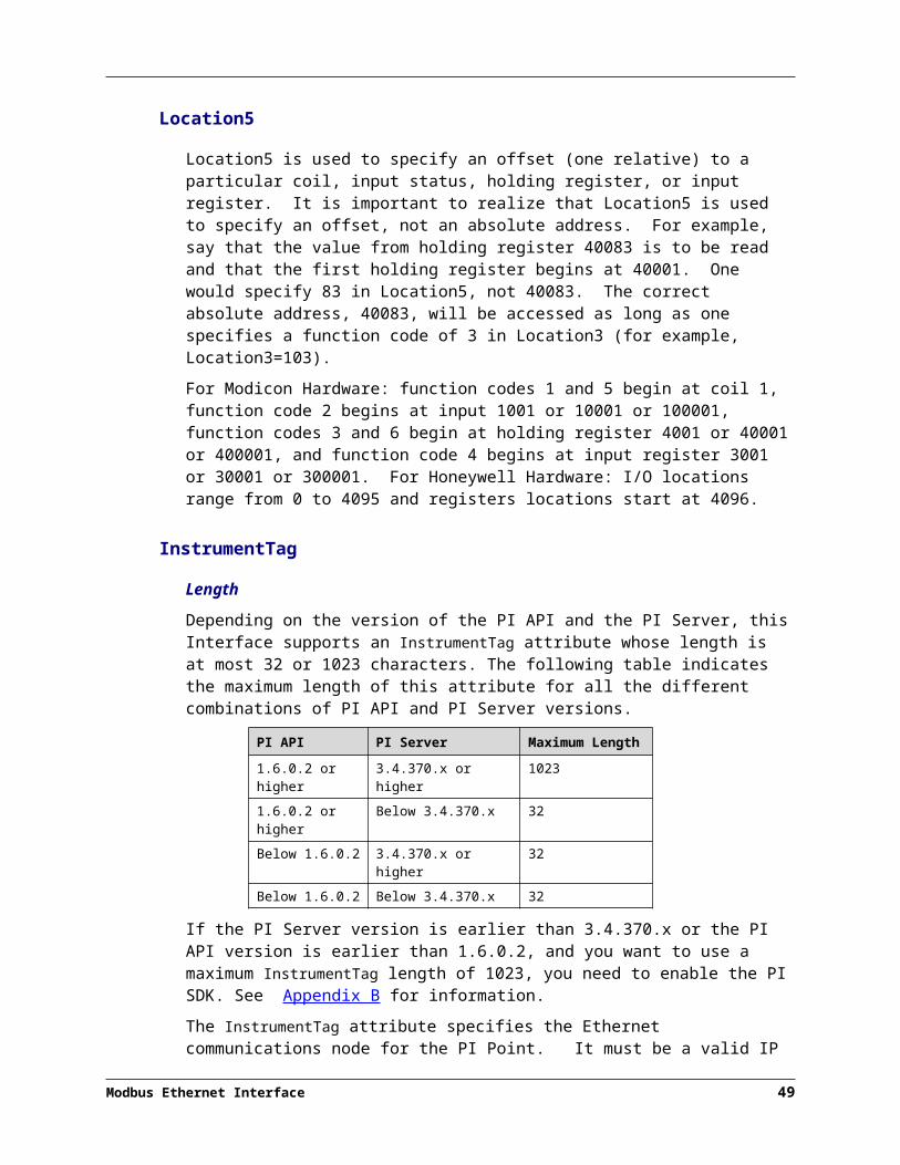
Since the ModbusE Interface is a UniInt-based interface, in some cases the user will need to make appropriate selections in the UniInt page. This page allows the user to access UniInt features through the PI ICU and to make changes to the behavior of the interface.
To set up the interface as a Windows Service, use the Service page. This page allows configuration of the interface to run as a service as well as to starting and stopping of the interface. The interface can also be run interactively from the PI ICU. To do that go to menu, select the Interface item and then Start Interactive.
For more detailed information on how to use the above-mentioned and other PI ICU pages and selections, please refer to the PI Interface Configuration Utility User Manual. The next section describes the selections that are available from the ModbusE page. Once selections have been made on the PI ICU GUI, press the Apply button in order for PI ICU to make these changes to the interface’s startup file.
ModbusE Interface page
Since the startup file of the ModbusE Interface is maintained automatically by the PI ICU, use the ModbusE page to configure the startup parameters and do not make changes in the file manually. The following is the description of interface configuration parameters used in the PI ICU Control and corresponding manual parameters.
Modbus Ethernet Interface 57

Startup Command File
ModbusE
The ModbusE ICU Control for PI ICU has 1 tab. A yellow text box indicates that an invalid value has been entered, or that a required value has not been entered.
Since the ModbusE interface supports multiple Ethernet nodes which have quite a number of possible parameters per node, the configuration is done through an external utility program called the Modbus Ethernet Interface Configurator. This utility is launched from this page using the interface configuration file specified.
Interface Configuration FileThis field is provided for the full path and name of the interface configuration file. This can be entered manually or by selecting the corresponding browse button to determine the path and name of the file (/ICF=<UNC Path>).
Launch Configuration UtilityThis button is provided to actually launch the configuration utility. It is disabled until the Interface Configuration File field has been set.
58

Additional ParametersThis section is provided for any additional parameters that the current ICU Control does not support.
Note: The UniInt Interface User Manual includes details about other command-line parameters, which may be useful.
Command-line Parameters
The following table shows the command-line parameters which can be used when configuring the interface using the ICU. See the section Configuration File Parameters for the additional command parameters which were moved from the command-line parameters into the Modbus Configuration File or are new with this version of the interface.
ICU Command-Line Parameters
Parameter Description
/CacheModeRequiredDefault: Not Defined
Required for disconnected startup operation. If defined, the /CacheMode startup parameter indicates that the interface will be configured to utilize the disconnected startup feature.
/CachePath=pathOptionalDefault: Not Defined
Used to specify a directory in which to create the point caching files. The directory specified must already exist on the target machine. By default, the files are created in the same location as the interface executable.If the path contains any spaces, enclose the path in quotes.Examples:/CachePath=D:\PIPC\Interfaces\CacheFiles/CachePath=D:/PIPC/Interfaces/CacheFiles/CachePath=D:/PIPC/Interfaces/CacheFiles/
Examples with space in path name:/CachePath=”D:\Program Files\PIPC\MyFiles”/CachePath=”D:/Program Files/PIPC/MyFiles”/CachePath=”D:/Program Files/PIPC/MyFiles/”
Modbus Ethernet Interface 59

Startup Command File
Parameter Description
/CacheSynch=#OptionalDefault: 250 ms
NOTE: Care must be taken when modifying this parameter. This value must be less than the smallest scan class period defined with the /f parameter. If the value of the /CacheSynch parameter is greater than the scan class value, input scans will be missed while the point cache file is being synchronized.The optional /CacheSynch=# startup parameter specifies the time slice period in milliseconds (ms) allocated by UniInt for synchronizing the interface point cache file with the PI Server. By default, the interface will synchronize the point cache if running in the disconnected startup mode. UniInt allocates a maximum of # ms each pass through the control loop synchronizing the interface point cache until the file is completely synchronized. Synchronization of the point cache file can be disabled by setting the value /CacheSynch=0. The minimum synchronization period when cache synchronization is enabled is 50ms Whereas, the maximum synchronization period is 3000ms (3s). Period values of 1 to 49 will be changed by the interface to the minimum of 50ms and values greater than 3000 will be set to the maximum interval value of 3000ms. Default: 250 msRange: {0, 50 – 3000} time in millisecondsExample: /CacheSynch=50 (use a 50ms interval) /CacheSynch=3000 (use a 3s interval) /CacheSynch=0 (do not synchronize the cache)
/ec=#Optional
The first instance of the /ec parameter on the command-line is used to specify a counter number, #, for an I/O Rate point. If the # is not specified, then the default event counter is 1. Also, if the /ec parameter is not specified at all, there is still a default event counter of 1 associated with the interface. If there is an I/O Rate point that is associated with an event counter of 1, each copy of the interface that is running without /ec=#explicitly defined will write to the same I/O Rate point. This means either explicitly defining an event counter other than 1 for each copy of the interface or not associating any I/O Rate points with event counter 1. Configuration of I/O Rate points is discussed in the section called I/O Rate Point.For interfaces that run on Windows nodes, subsequent instances of the /ec parameter may be used by specific interfaces to keep track of various input or output operations. Subsequent instances of the /ec parameter can be of the form /ec*, where * is any ASCII character sequence. For example, /ecinput=10, /ecoutput=11, and /ec=12 are legitimate choices for the second, third, and fourth event counter strings.
/f=SS.##or/f=SS.##,SS.##or
The /f parameter defines the time period between scans in terms of hours (HH), minutes (MM), seconds (SS) and sub-seconds (##). The scans can be scheduled to occur at discrete moments in time with an optional time offset specified in terms of hours (hh),
60

Parameter Description
/f=HH:MM:SS.##or/f=HH:MM:SS.##,hh:mm:ss.##
Required for reading scan-based inputs
minutes (mm), seconds (ss) and sub-seconds (##). If HH and MM are omitted, then the time period that is specified is assumed to be in seconds. Each instance of the /f parameter on the command-line defines a scan class for the interface. There is no limit to the number of scan classes that can be defined. The first occurrence of the /f parameter on the command-line defines the first scan class of the interface; the second occurrence defines the second scan class, and so on. PI Points are associated with a particular scan class via the Location4 PI Point attribute. For example, all PI Points that have Location4 set to 1 will receive input values at the frequency defined by the first scan class. Similarly, all points that have Location4 set to 2 will receive input values at the frequency specified by the second scan class, and so on. Two scan classes are defined in the following example:/f=00:01:00,00:00:05 /f=00:00:07or, equivalently:/f=60,5 /f=7The first scan class has a scanning frequency of 1 minute with an offset of 5 seconds, and the second scan class has a scanning frequency of 7 seconds. When an offset is specified, the scans occur at discrete moments in time according to the formula:scan times = (reference time) + n(frequency) + offsetwhere n is an integer and the reference time is midnight on the day that the interface was started. In the above example, frequency is 60 seconds and offset is 5 seconds for the first scan class. This means that if the interface was started at 05:06:06, the first scan would be at 05:07:05, the second scan would be at 05:08:05, and so on. Since no offset is specified for the second scan class, the absolute scan times are undefined.The definition of a scan class does not guarantee that the associated points will be scanned at the given frequency. If the interface is under a large load, then some scans may occur late or be skipped entirely. See the section “Performance Summaries” in the UniInt Interface User Manual.doc for more information on skipped or missed scans.Sub-second Scan ClassesSub-second scan classes can be defined on the command-line, such as/f=0.5 /f=00:00:00.1where the scanning frequency associated with the first scan class is 0.5 seconds and the scanning frequency associated with the second scan class is 0.1 of a second.Similarly, sub-second scan classes with sub-second offsets can be defined, such as/f=0.5,0.2 /f=1,0Wall Clock SchedulingScan classes that strictly adhere to wall clock
Modbus Ethernet Interface 61
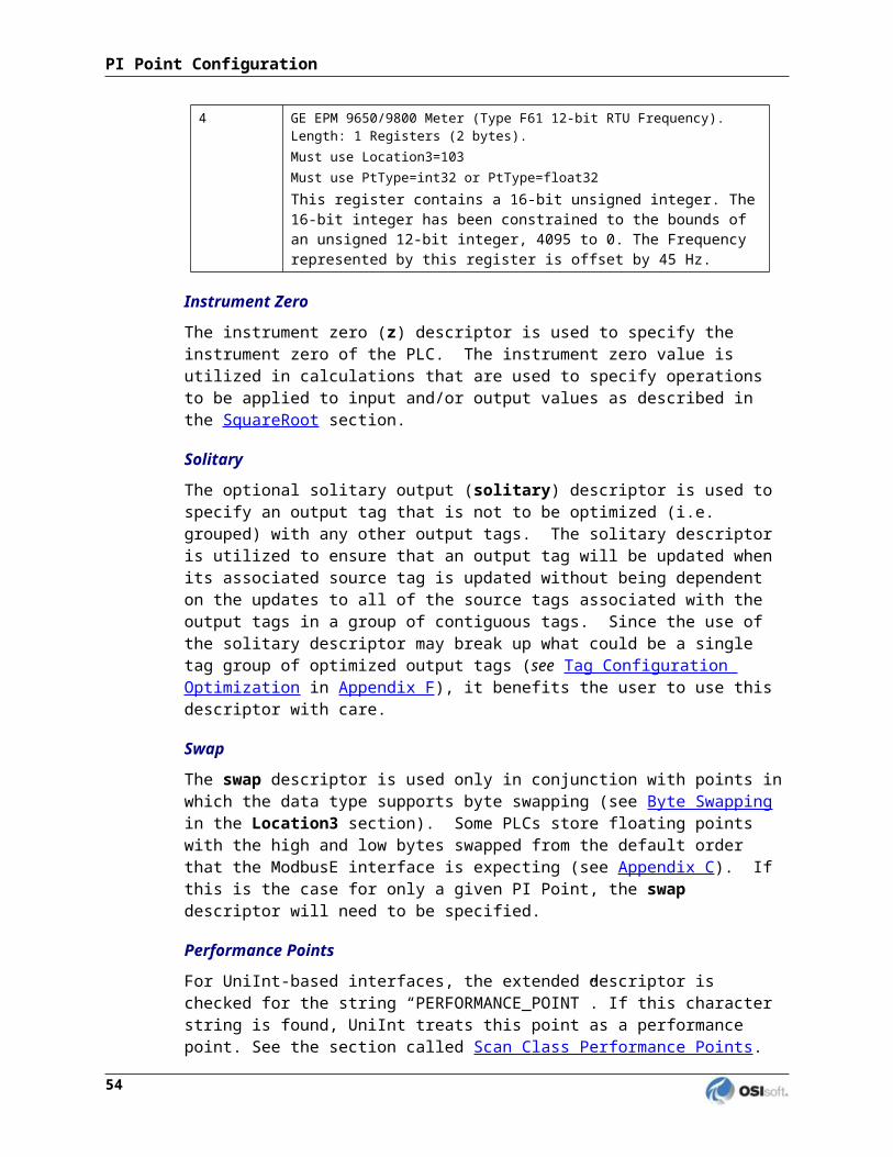
Startup Command File
Parameter Description
scheduling are now possible. This feature is available for interfaces that run on Windows and/or UNIX. Previously, wall clock scheduling was possible, but not across daylight saving time. For example, /f=24:00:00,08:00:00 corresponds to 1 scan a day starting at 8 AM. However, after a Daylight Saving Time change, the scan would occur either at 7 AM or 9 AM, depending upon the direction of the time shift. To schedule a scan once a day at 8 AM (even across daylight saving time), use /f=24:00:00,00:08:00,L. The ,L at the end of the scan class tells UniInt to use the new wall clock scheduling algorithm.
/host=host:portRequired
The /host parameter is used to specify the PI Home node. Host is the IP address of the PI Sever node or the domain name of the PI Server node. Port is the port number for TCP/IP communication. The port is always 5450. It is recommended to explicitly define the host and port on the command-line with the /host parameter. Nevertheless, if either the host or port is not specified, the interface will attempt to use defaults. Examples:The interface is running on a PI Interface Node, the domain name of the PI home node is Marvin, and the IP address of Marvin is 206.79.198.30. Valid /host parameters would be:/host=marvin/host=marvin:5450/host=206.79.198.30/host=206.79.198.30:5450
/icf=xRequired
The /icf parameter defines the ModbusE interface configuration file name. x must be a valid file name with a .csv extension that contains the interface and communications configuration for each Ethernet node. Since the interface generally runs as a service, it is imperative that x is the full path of the file (e.g. /icf=”C:\Program Files\PIPC\Interfaces\Modbus\ModbusEConfig.csv”).The Modbus communication configuration file is discussed in detail in the Interface Configuration File section of this document.
/id=xRequired
The /id parameter is used to specify the interface identifier. The interface identifier is a string that is no longer than 9 characters in length. UniInt concatenates this string to the header that is used to identify error messages as belonging to a particular interface. See the Appendix A Error and Informational Messages for more information.UniInt always uses the /id parameter in the fashion described above. This interface also uses the /id parameter to identify a particular interface copy number that corresponds to an integer value that is assigned to Location1. For this interface, use only numeric characters in the identifier. For example,/id=1
62

Parameter Description
/ps=xRequired
The /ps parameter specifies the point source for the interface. X is not case sensitive and can be any multiple character string. For example, /ps=P and /ps=p are equivalent. The point source that is assigned with the /ps parameter corresponds to the PointSource attribute of individual PI Points. The interface will attempt to load only those PI points with the appropriate point source. If the PI API version being used is prior to 1.6.x or the PI Server version is prior to 3.4.370.x, the PointSource is limited to a single character unless the SDK is being used.
/sioOptional
The /sio parameter stands for “suppress initial outputs.” The parameter applies only for interfaces that support outputs. If the /sio parameter is not specified, the interface will behave in the following manner.When the interface is started, the interface determines the current Snapshot value of each output tag. Next, the interface writes this value to each output tag. In addition, whenever an individual output tag is edited while the interface is running, the interface will write the current Snapshot value to the edited output tag.This behavior is suppressed if the /sio parameter is specified on the command-line. That is, outputs will not be written when the interface starts or when an output tag is edited. In other words, when the /sio parameter is specified, outputs will only be written when they are explicitly triggered.
Modbus Ethernet Interface 63

Startup Command File
Parameter Description
/stopstator/stopstat=digstate
Default:/stopstat="Intf Shut"Optional
If the /stopstat parameter is present on the startup command line, then the digital state Intf Shut will be written to each PI Point when the interface is stopped. If /stopstat=digstate is present on the command line, then the digital state, digstate, will be written to each PI Point when the interface is stopped. For a PI 3 Server, digstate must be in the system digital state table. UniInt uses the first occurrence in the table.If neither /stopstat nor /stopstat=digstate is specified on the command line, then no digital states will be written when the interface is shut down.Note: The /stopstat parameter is disabled If the interface is running in a UniInt failover configuration as defined in the UniInt Failover Configuration section of this manual. Therefore, the digital state, digstate, will not be written to each PI Point when the interface is stopped. This prevents the digital state being written to PI Points while a redundant system is also writing data to the same PI Points. The /stopstat parameter is disabled even if there is only one interface active in the failover configuration.Examples:/stopstat=shutdown/stopstat="Intf Shut"The entire digstate value should be enclosed within double quotes when there is a space in digstate.
/UFO_ID=#Required for UniInt Interface Level Failover Phase 1 or 2
Failover ID. This value must be different from the Failover ID of the other interface in the failover pair. It can be any positive, non-zero integer.
/UFO_Interval=#
OptionalDefault: 1000Valid values are 50-20000.
Failover Update IntervalSpecifies the heartbeat Update Interval in milliseconds and must be the same on both interface computers.This is the rate at which UniInt updates the Failover Heartbeat tags as well as how often UniInt checks on the status of the other copy of the interface.
/UFO_OtherID=#
Required for UniInt Interface Level Failover Phase 1 or 2
Other Failover ID. This value must be equal to the Failover ID configured for the other interface in the failover pair.
64

Parameter Description
/UFO_Sync=path/[filename]Required forUniInt Interface Level Failover Phase 2 synchronization.
Any valid pathname / any valid filenameThe default filename is generated as executablename_pointsource_interfaceID.dat
The Failover File Synchronization Filepath and Optional Filename specify the path to the shared file used for failover synchronization and an optional filename used to specify a user defined filename in lieu of the default filename.The path to the shared file directory can be a fully qualified machine name and directory, a mapped drive letter, or a local path if the shared file is on one of the interface nodes. The path must be terminated by a slash ( / ) or backslash ( \ ) character. If no d terminating slash is found, in the /UFO_Sync parameter, the interface interprets the final character string as an optional filename. The optional filename can be any valid filename. If the file does not exist, the first interface to start attempts to create the file.Note: If using the optional filename, do not supply a terminating slash or backslash character.If there are any spaces in the path or filename, the entire path and filename must be enclosed in quotes. Note: If you use the backslash and path separators and enclose the path in double quotes, the final backslash must be a double backslash (\\). Otherwise the closing double quote becomes part of the parameter instead of a parameter separator.Each node in the failover configuration must specify the same path and filename and must have read, write, and file creation rights to the shared directory specified by the path parameter. The service that the interface runs against must specify a valid logon user account under the “Log On” tab for the service properties.
/UFO_Type=type
Required for UniInt Interface Level Failover Phase 2.
The Failover Type indicates which type of failover configuration the interface will run. The valid types for failover are HOT, WARM, and COLD configurations.If an interface does not supported the requested type of failover, the interface will shut down and log an error to the pipc.log file stating the requested failover type is not supported.
Logging Flags
The ModbusE Interface allows the user to configure logging via the /logging startup command parameter. Logging will be turned off only if the /logging startup command parameter is set to zero.
Note: Even if the /logging parameter is set to zero, logging will still occur on critical errors. The logging flags are essentially used to allow logging of informational, warning and non-critical error messages.
Most logging flags are used to turn on logging of messages for particular issues in the interface. The exceptions are the Reduced, Warning and Info logging flags. The Warning flag must be turned on to log warning messages and the Info flag must be turned on to log informational messages.
Modbus Ethernet Interface 65

Startup Command File
The table below lists all of the logging flags with their corresponding values:
Flag Value Description
Communications 1 Log communications issues.
Requests 2 Log Modbus request issues.
Responses 4 Log Modbus response issues.
Tags 8 Log tag issues.
Parameter 16 Log parameter issues.
Configuration 32 Log configuration failures.
Exception 64 Log Modbus response exceptions.
Reduced 8192 Reduced logging enabled (see Reduced Logging for more details).
Warning 16384 Log warning messages.
Info 32768 Log informational messages.
Run-time Configuration Flag
The ModbusE Interface allows the user to dynamically add and remove Ethernet nodes via the /pcf command parameter. If the value is 1 nodes cannot only be enabled, disabled, added or removed, but all of the other node parameters can be modified without having to shutdown and restart the interface
Reduced Logging
The ModbusE Interface allows the user to reduce logging by use of the messages per interval (/mpi) and the log suspension interval (/lsi) command parameters. If reduced logging is enabled, the number of messages indicated by the messages per interval parameter is the maximum number of messages that can be logged within the log suspension interval. If /mpi is set to 15 and the /lsi is set to 10, then the interface will log a maximum of fifteen messages every ten seconds. This cycle of maximum messages within a suspension interval will repeat until either the interface terminates or reduced logging is turned off.
If either the /mpi or the /lsi startup command parameter is set, reduced logging will be enabled automatically (the /logging flag Reduced will be set). If one of the parameters is set and the other is not, the other parameter will be automatically set to its default value.
If the Modbus Interface Configurator is used to configure reduced logging, setting the Reduced logging flag (as shown in Logging) will enable both the messages per interval and the log suspension interval parameter values (as shown in Reduced Logging). Likewise clearing the Reduced logging flag will disable both parameter values.
66

Sample PIModbusE.bat File
The following is an example file:REM===============================================================REMREM PIModbusE.batREMREM Sample startup file for the Modbus Ethernet InterfaceREMREM===============================================================REM REM OSIsoft strongly recommends using PI ICU to modify startup files.REMREM Sample command lineREM .\PIModbusE.exe ^
/ID=1 ^/PS=ModbusE ^/host=XXXXXX:5450 ^/ICF="C:\Program Files\PIPC\Interfaces\ModbusE\ModbusE1.csv" ^/sio ^/f=5 ^/f=8
REMREM End of PIModbusE.bat File
Modbus Ethernet Interface 67

Chapter 10. Interface Configuration File
The ModbusE interface requires several parameters for each Ethernet node and the interface itself for successful execution. The parameters are set in an interface configuration file. This file is called, for example, ModbusEConfig.csv. A sample startup configuration file is provided by the install kit.
The configuration file, known as the ModbusE interface configuration file, is a comma-separated values file in which one line describes the interface and every other line describes a single Ethernet node. Although this file can be created and modified manually, it is best for the user to use the Modbus Interface Configurator to create and modify the file.
Modbus Interface Configurator
The Modbus Interface Configurator (PI MIC) is a tool for configuring the ModbusE Interface and the Ethernet nodes in the interface configuration file.
The Modbus Interface Configurator provides a graphical user interface for configuring every Ethernet node used by an instance of a ModbusE Interface and the interface itself. If the interface is configured by the utility, the comma-separated values interface configuration file (e.g. ModbusEConfig.csv) for the interface will be maintained by the utility and all configuration changes will be kept in that file.
To use the Modbus Interface Configurator a user must run the PIModbusE_Configurator.exe executable file. A window such as the following appears:
Modbus Ethernet Interface 69

The following sections describe the procedures to use the Modbus Interface Configurator tool and describe the elements of the graphical user interface of the application:
Open
From the PI MIC menu, select Open. The Open Interface Configuration File dialog box appears:
Modbus Ethernet Interface 70

Navigate to the directory containing the configuration file (e.g. ModbusEConfig.csv), select the file name and then select Open. The Nodes list will be populated with the nodes in the configuration file and the first node in the list will be selected.
Note: The Open option is only available when the Modbus Interface Configurator is run as a stand-alone application. Normally the Configurator will be launched from the Interface Configuration Utility (ICU) in which case the full path name of the configuration file and the interface ID will be supplied to the Configurator. In this case the Open option will be unavailable to the user because only the given configuration file will be configurable for the interface instance being configured.
Save
From the PI MIC menu, select Save. In the normal circumstance in which the PI MIC is launched from the Interface Configuration Utility, the Save option will save the configuration file that was specified when the Configurator was launched. In the case in which the PI MIC is run as a stand-alone application, select the Save option to display the Save Interface Configuration File dialog box as shown below:
Navigate to the directory containing the configuration file or enter the configuration file name (e.g. ModbusEConfig.csv) in the File name field, and then select Save. The interface configuration and all of the nodes in the Nodes list will be written to the specified configuration file.
Preview
From the PI MIC menu, select Preview. The Preview of Configuration File window appears:
Modbus Ethernet Interface 71

Interface Configuration File
Edit
From the PI MIC menu, select Edit. A menu of the Nodes list editing commands appears:
Note: The commands to add, remove, copy and rename nodes are only available when the Nodes Tab is active. The commands are described in the Ethernet nodes section.
Interface Tab
The Interface tab of the utility contains all the interface configuration parameters that are specific to ModbusE and that can be changed at run-time (unless otherwise noted) as shown below:
72

Interface IDThe Interface ID field allows the user to select the interface identifier for which the interface configuration file will be associated (/id=#). The /id parameter value is not a configurable value in the sense that it is used to configure the interface. Its sole purpose is to verify that the configuration file corresponds to the instance of the interface that read the file.
Note: The Interface ID value is not editable when the Configurator is launched from the PI Interface Configuration Utility (ICU). Since the ID of the interface being configured in the ICU has already been determined, the Configurator will disable the value as shown in the figure above.
Run-time ConfigurationThe Run-time Configuration group of checkbox buttons gives the user the ability to enable run-time configuration of Ethernet nodes for the interface:
Allow configurationThis enables run-time configuration of Ethernet nodes (/pcf=#).
Reduced LoggingThe Reduced Logging group of fields allows the user the ability to enable reduced logging and set the maximum number of messages that may be logged within an interval of time:
Reduce LoggingThis enables reduced logging. If Reduce Logging is not checked the Messages per Interval and Log Suspension Interval values will be disabled.
Messages per IntervalThis value is used to specify the maximum number of messages that may be logged during the log suspension interval (/mpi=#).
Log Suspension IntervalThis value is used to specify the log suspension interval, in seconds, that messages may be logged until the maximum limit is reached (/lsi=#).
Modbus Ethernet Interface 73

Interface Configuration File
System Status CodesThe System Status Codes group of fields allows the user the ability to set a custom value for the system digital state to be used for the status of a tag when the device it is associated with is disabled. The default value is 213 which is the system digital state number for the Unit Down state, but the user can create a custom system digital state name for any unused state number:
Device DisabledThis value is used to specify the system digital state number to be used when a device is disabled (/ddsysstate=#).
Output Point ValuesThe Output Point Values group allows the user the ability to record the value of the source tag as the output tag value without any preprocessing of the value. The default state is that output point values may be processed with conversion formulas before being recorded:
Record preprocessedThis value is used to enable the output point values to be recorded without preprocessing (/rpov=#).
Ignore FlagsThe Ignore Flags group of checkboxes allows the user the ability to ignore some or all of the Modbus and unknown exceptions that may occur when communicating with a device and to ignore the failover triggers caused by a change to a device status.
All exceptionsThis value is used to specify that all exceptions will be ignored and a retry of the request will be done (/ialler=#).
74
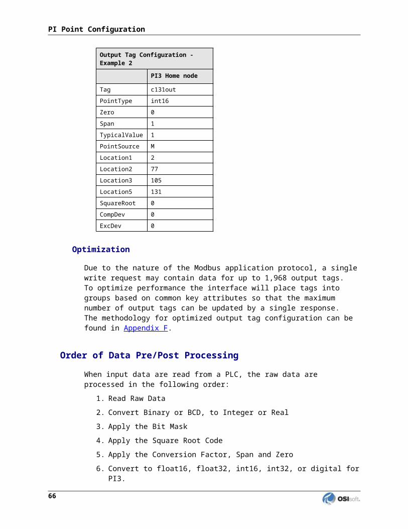
CRC and unknown exceptionsThis value is used to specify that the CRC exception and all unknown exceptions will be ignored and a retry of the request will be performed (/icrcer=#). Note that this will be automatically set if All exceptions is set.
Device Status failover triggersThis value is used to specify that a change to the device status will not trigger a failover (/idevstat=#). For more information on the device status and failover see the UniInt Failover Configuration chapter.
LoggingThe Logging group of checkbox buttons gives the user the ability to turn on and off logging for particular types of PI log messages (/logging=#). Logging is described in more detail in the Logging Flags section:
CommunicationsLog communications issues.
RequestsLog Modbus request buffer issues.
ResponsesLog Modbus response buffer issues.
TagsLog tag issues.
ParametersLog parameter issues.
ConfigurationLog configuration failures.
Modbus Ethernet Interface 75

Interface Configuration File
ExceptionsLog Modbus exception responses.
WarningsLog warning messages.
InformationLog informational messages.
76

Interface TraceThe Interface Trace group of fields gives the user the ability to turn on and off debug tracing for particular actions and data in the interface. Since most tracing is node specific, tracing at the level of the interface is confined to areas of the interface in which a node is unknown or has not been configured. In general, tracing need only be turned on when instructed by OSIsoft technical support personnel. Tracing is described in more detail in the Trace Flags section (/debug=#).
The trace group of checkbox buttons gives the user the ability to turn on and off debug tracing for particular actions and data in the interface. Since most tracing is node specific, tracing at the level of the interface is confined to areas of the interface in which a node is unknown or has not been configured. In general, tracing need only be turned on behalf of OSIsoft technical support personnel. Tracing is described in more detail in the Trace Flags section (/debug=#).
Note: The trace group of checkbox buttons is the same as the trace group described in the Trace section of the Nodes Tab below.
Maximum number of trace filesThis value is used to specify the maximum number of trace files that may be created during the execution of the interface (/dtfmax=#).
Modbus Ethernet Interface 77

Interface Configuration File
Nodes Tab
The Nodes Tab of the utility contains all of the Ethernet node configuration parameters that can be changed at run-time (unless otherwise noted) as shown below:
NodesThe Nodes group of fields allows the user the ability to add, remove and edit the Ethernet nodes and their related parameters.
Nodes listLists each configured Ethernet node. Any Ethernet node listed that is not checked is disabled (/disabled=1).
78

IP Address/HostnameThe IP address or hostname (/dn=address:#).
PortThe Ethernet port number (/dn=address:#).
AddAdds the node identified by the values in the IP Address/Hostname and Port fields to the Nodes list.
RemoveRemoves the node selected in the Nodes list from the list.
EditIn the Nodes list, right click the mouse and the popup menu show below appears:
In addition to the Add and Remove nodes commands described above, the user is given the option to rename the selected Ethernet node or copy the settings of the selected Ethernet node to another Ethernet node.
TimingThe Modbus Ethernet communications timing group of controls allows the user the ability to set the following communications delays and timeouts for the selected Ethernet node:
Poll DelayThis is used to specify a minimum delay time between scans, specified in milliseconds (/polldelay=#).
Modbus Ethernet Interface 79

Interface Configuration File
Write DelayThis is used to specify a minimum delay time between outputs, specified in milliseconds (/writedelay=#).
Response TimeoutThis is used to specify a maximum wait time for a response, specified in seconds (/to=#).
Request RetriesThis is used to specify a maximum number of requests before a failure is logged and IO Timeout is written to all affected tags (/cn=#).
Request LengthThis is used to specify the request length, specified in bytes, of Modbus messages (/requestlen=#). If the request length is set to 0, the interface will automatically use 100 bytes for function codes 1 and 2 and 200 bytes for all other function codes. Otherwise, all requests will use the number of bytes specified.
Byte SwapThe byte swap group of controls allows the user the ability to change the byte order from the default order for tags of a specified data type on the selected Ethernet node that the Modbus interface is expecting (see Appendix C):
Data Type 4This parameter (/swap4) is used only in conjunction with points of data type 4 (see section Location3).
Data Type 6This parameter (/swap6) is used only in conjunction with points of data type 6 (see section Location3).
Data Type 7This parameter (/swap7) is used only in conjunction with points of data type 7 (see section Location3).
Data Type 13This parameter (/swap13) is used only in conjunction with points of data type 13 (see section Location3).
80

Data Type 15This parameter (/swap15) is used only in conjunction with points of data type 15 (see section Location3).
Data Type 16This parameter (/swap16) is used only in conjunction with points of data type 16 (see section Location3).
StringThis parameter (/swapstring) is used only in conjunction with points of string data types (see section Location3).
TCP/IP HeaderSince some Modbus TCP/IP systems may not support the standard Modbus Application Protocol (MBAP) header, an optional parameter (/hcp) is provided so that the message packets do not use the standard header (see Appendix D: Modbus Message Packets for more details):
Node TraceThe trace group of buttons and fields gives the user the ability to turn on and off debug tracing for particular actions and data in the interface for the selected Ethernet node. In general, tracing need only be turned on when instructed by OSIsoft technical support personnel. Tracing is described in more detail in the Trace Flags section (/debug=#).
RequestsTrace the Modbus request buffers.
Modbus Ethernet Interface 81

Interface Configuration File
ResponsesTrace the Modbus response buffers.
Scan ListsTrace the scan list processing control.
Tag GroupsTrace the tag groups that represent a group of tags to request.
Device PointsTrace the device points that represent a tag in the interface.
TagsTrace the tags (i.e. PI points) in the interface.
CommunicationsTrace the general flow of communications such as opening, closing and reconnecting Ethernet nodes.
IOCPTrace the flow of communications within the IO Completion Port subsystem.
Tag loadingTrace when tags are being loaded.
Tag removalTrace when tags are being removed (and edited).
HibernationTrace when tags are being processed and updated.
InputsTrace when input tags are scanned.
OutputsTrace when output tags are scanned.
Mark AllTurn on all tracing flags by checking all trace flags.
Clear AllTurn off all tracing flags by clearing all trace flags.
82

Trace TagThe trace tag control allows the user to enter the long name of a single tag for which more extensive tracing will be written to the trace file (/tracetag=x). If a valid trace tag is entered, the named tag will be trace regardless of the settings of any other trace flags.
Note: If the /tracetag parameter is set to a valid tag name, tracing will be turned on even if no trace flags are set on the Ethernet node. In other words, /tracetag is treated as another trace flag.
Configuration File Parameters
Although the Modbus Interface Configurator should be used to configure the parameters, all of the required and optional parameters are listed in the table below as they are used in the interface configuration file. Since many of the parameters were available in previous versions of the Modbus interface, the same parameter key names are being used for the familiarity of previous users:
Parameter Description
/cn=xoptional,default: 1
The number specified by the /cn parameter is the number of successive communication failures that must occur before an error is logged and IO Timeout is written to the affected tags. The /cn parameter is useful during serial communication because serial communication frequently fails on 1 attempt but succeeds after an immediate retry. The default value for /cn is 1, and the maximum value is 4.
/debug=#Optional,default: 0
The /debug parameter defines the debug tracing flags and whether tracing is turned on. If # is 0 tracing is turned off. Otherwise # is the addition of one or more of the trace flag values as defined in the Trace Flags section. The default value of # is 0.Since almost all tracing is done at the node level, most trace flags at the level of the interface will have no effect. The principle advantage of having # a non-zero value is to ensure that tracing is always turned on. If # is 0 tracing may still be turned on if any Ethernet nodes have tracing turned on. In addition, if # is 0, the user has the option of turning tracing on or off by changing the trace flags of one or more Ethernet nodes.
/disabled=#optional
The /disabled parameter defines whether the Ethernet node is disabled or not. If # is 1 the Ethernet node is disabled and the
interface does not attempt to scan the node. If # is 0 the node is enabled. The default value of # is 0.NOTE: An Ethernet node may be enabled or disabled while the interface is running.
Modbus Ethernet Interface 83

Interface Configuration File
Parameter Description
/dn=x:prequired
The /dn parameter defines the device name (Ethernet node) in which x:p represents the node (e.g. 192.168.70.190:502). x must be a valid IP address or host name and p must be a valid service port in which x is separated from p by a colon. For example, node 192.168.70.190:502 consists of IP address 192.168.70.190 and port 502.
/dtf=xOptional
The /dtf parameter defines the debug trace file name for the trace output when tracing is turned on and x must be a valid file name that has a .txt extension. If the /dtf parameter is not defined, the trace file name will be generated by the interface. It will be in the form PIModbusE_Trace_Intf_nn.txt in which nn is the zero padded interface ID (the value specified by the /id parameter). For example, the file name for an interface with an ID of 3 would be PIModbusE_Trace_Intf_03.txt.
/dtfmax=#Optional,default: 10
The /dtfmax parameter defines the maximum number of debug trace files that may be generated during the execution of the interface. # must be an integer value between 1 and 100. The default value of # is 10.
/hcpoptional
The /hcp parameter indicates that the standard Modbus Application Protocol (MBAP) header is not used in message packets.
/ialler=xOptional
The /ialler parameter is used to ignore all exceptions and retry the request. x must be 1 to be enabled. Otherwise it will be ignored.
/icrcer=xOptional
The /icrcer parameter is used to ignore all CRC and unknown exceptions and retry the request. x must be 1 to be enabled. Otherwise it will be ignored.
/idevstat=xOptional
The /idevstat parameter is used to ignore some device status changes that may trigger a failover. x must be 1 to be enabled. Otherwise it will be ignored.
/logging=#Optional,Default: 57343
The /logging parameter defines the logging flags and whether logging is turned on. If # is 0 logging is turned off. Otherwise # is the addition of one or more of the logging flag values as defined in the Logging Flags section. The default value of # is 57343 (all logging flags are turned on except for reduced logging).
/lsi=#Optional,Default: 10
The /lsi parameter specifies the log suspension interval of reduced logging for the interface as described in the Reduced Logging section. If reduced logging is enabled # is the interval in seconds that a maximum number of messages (/mpi) will be logged. # must be an integer value between 1 and 1000 seconds. The default value of # is 10 seconds.
/mpi=#Optional,Default: 10
The /mpi parameter specifies the messages per interval of reduced logging for the interface as described in the Reduced Logging section. If reduced logging is enabled # is the maximum number of messages that will be logged during the log suspension interval (/lsi). # must be an integer value between 1 and 1000. The default value of # is 10.
84

Parameter Description
/pcf=#Optional,Default: 0
The /pcf parameter specifies the dynamic run-time configuration flags for the interface. If # is 0 dynamic node configuration is turned off. Otherwise # is the addition of one or more of the logging flag values as defined in the Run-time Configuration Flags section. The default value of # is 0.
/polldelay=#optional,default: 0
The /polldelay parameter is used to specify a minimum delay time between scans. # is the delay time in milliseconds and must be an integer value of 0 to 10,000 milliseconds.Sometimes it is possible for the Modbus interface to send commands to a device at a faster rate than the device can handle the messages. The problem is most likely to occur when the same device is scheduled to be scanned from two different scan classes when the scan time coincides for the two scan classes. For example, /f=5,0 and /f=10,0 will coincide every 10 seconds.One possible symptom of an insufficient /polldelay are IO Timeouts reported by the interface. The default poll delay is 0 milliseconds. The delay should not need to be increased above 100 milliseconds.
/requestlen=#optional,see description for default
The request length for Modbus messages can be adjusted to between 10 and 250 bytes. The default is 100 bytes for function codes 1 and 2 and 200 bytes for the remaining function codes. When the /requestlen parameter is used, the number of bytes that are read by all function codes are the same.
/swap4optional
This parameter is used only in conjunction with points of data type 4 (see location3 under “PI Point Definition”). Some PLCs store floating points with the high and low bytes swapped from the default order that the Modbus interface is expecting (see Appendix C). If this is the case, the /swap4 parameter will need to be specified as an Ethernet node parameter.
/swap6optional
This parameter is used only in conjunction with points of data type 6 (see location3 under “PI Point Definition”). This parameter is required to read floating points from Modicon PLCs. Basically, some PLCs store floating points with the high and low bytes swapped from the default order that the Modbus interface is expecting (see Appendix C). If this is the case, the /swap6 parameter will need to be specified as an Ethernet node parameter.
/swap7optional
This parameter is used only in conjunction with points of data type 7 (see location3 under “PI Point Definition”). Some PLCs store 4-byte integers with the high and low bytes swapped from the default order that the Modbus interface is expecting (see Appendix C). If this is the case, the /swap7 parameter will need to be specified as an Ethernet node parameter.
/swap13optional
This parameter is used only in conjunction with data type 13 (8-Byte Signed Integer). When the /swap13 parameter is specified, the interface will expect the bytes that are sent from the PLC in a different order than the default order.
Modbus Ethernet Interface 85
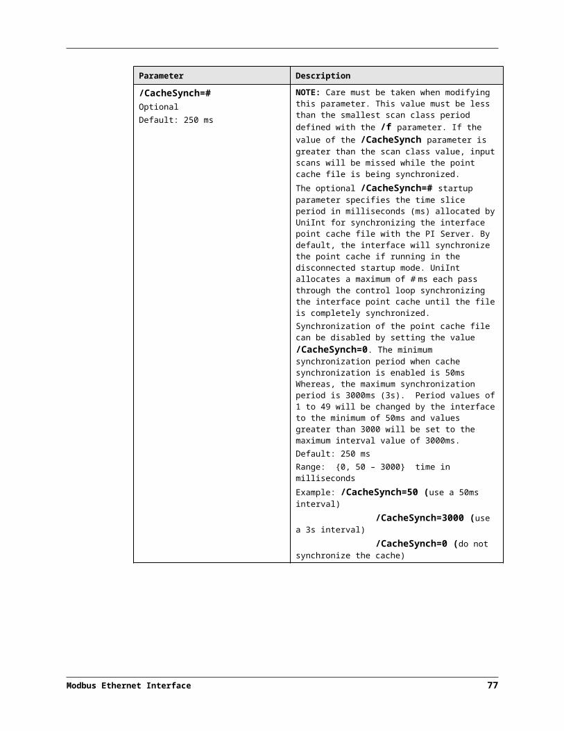
Interface Configuration File
Parameter Description
/swap15optional
This parameter is used only in conjunction with data type 15 (8-Byte Unsigned Integer). When the /swap15 parameter is specified, the interface will expect the bytes that are sent from the PLC in a different order than the default order.
/swap16optional
This parameter is used only in conjunction with data type 16 (double precision IEEE floating point). When the /swap16 parameter is specified, the interface will expect the bytes that are sent from the PLC in a different order than the default order.
/swapstringoptional
This parameter is used in conjunction with data types 101 and higher. These data types are for reading strings of varying lengths into PI tags (see location3 under “PI Point Definition”). The /SwapString parameter reverses the byte order in each 16-byte register.
/to=#default: 2optional
Defines the number of seconds that the interface waits for an answer from a node before a timeout occurs. # is an integer from 1 to 300. The default is 2 seconds. It is not recommended to set the timeout above 10 seconds unless there truly is a need. If the timeout is set unnecessarily high, then the interface will wait for a period of time equal to the product of the /to and /cn parameters every time that the interface tries to read from a node that is offline. This could impede data collection from other nodes that are not experiencing problems.
/tracetag=xrequired
The /tracetag parameter specifies the name of a single tag for which more extensive tracing will be written. x must be in the long name form of a valid tag.
/writedelay=#optional,default: 0
The /writedelay parameter is used to specify a minimum delay time between outputs. x is the delay time in milliseconds and must be an integer value of 0 to 10,000 milliseconds.Sometimes it is possible for the Modbus interface to send commands to a device at a faster rate than the device can handle the messages. The problem is most likely to occur if several outputs occur at the same time.One possible symptom of an insufficient /writedelay are IO Timeouts reported by the interface. The default write delay is 0 milliseconds. The delay should not need to be increased above 100 milliseconds.
Trace Flags
The Modbus Interface Configurator (PI MIC) allows the user to configure tracing via the /debug parameter on a node-by-node basis in conjunction with the /debug startup command-line parameter. Regardless of the value of the /debug command parameter, if the /debug parameter for any node has any trace flags set then tracing will be turned on. Tracing will be turned off only if the /debug startup command parameter is set to zero, no nodes have any trace flags turned on and no node has the /tracetag parameter set to a valid tag name.
86

There are two types of trace flags: flow flags, which determine at which point within the interface program flow that a trace will occur, and data flags, which determine what kind of data will be traced. For the most part, one flow flag and one data flag are required to trace a particular piece of data. For example, to trace a tag at the point of removal from the interface, both the Tags and Tag removal trace flags must be turned on (i.e. /debug=640).
The table below lists all of the trace flags with their corresponding types and values:
Flag Type Value DescriptionCommunications Flow 1 Trace the general flow of communications such
as opening, closing and reconnecting nodes.
ICOP Flow 2 Trace the flow of communications within the IO Completion Port subsystem.
Requests Data 4 Trace the Modbus request buffers.
Responses Data 8 Trace the Modbus response buffers.
Scan lists Data 16 Trace the scan list processing control.
Tag groups Data 32 Trace the tag groups that represent a group of tags to request.
Device Points Data 64 Trace the device points that represent a tag in the interface.
Tags Data 128 Trace the tags (i.e. PI points) in the interface.
Tag loading Flow 256 Trace when tags are being loaded.
Tag removal Flow 512 Trace when tags are being removed (and edited).
Hibernation Flow 1024 Trace when tags are being processed and updated.
Inputs Flow 2048 Trace when input tags are scanned.
Outputs Flow 4096 Trace when output tags are scanned.
Sample ModbusEConfig.csv File
The following is an example file:/id=1,/pcf=7,/mpi=20,/lsi=5,/logging=65535,/debug=57343,/dtfmax=25
/dn=COM11,/mode=[9600/8/0/0],/cn=3,/polldelay=100,/to=12,/writedelay=0,/debug=3311,/swap4,/swap6,/disabled=0
/dn=COM21,/mode=[2400/8/2/2],/cn=4,/polldelay=50,/to=5,/writedelay=0,/debug=0,/tracetag=TestTag65,/swap4,/swap7,/disabled=1
/dn=COM31,/mode=[2400/7/1/0],/cn=4,/polldelay=50,/to=2,/writedelay=0,/requestlen=200,/debug=0,/swap4,/disabled=1
Modbus Ethernet Interface 87
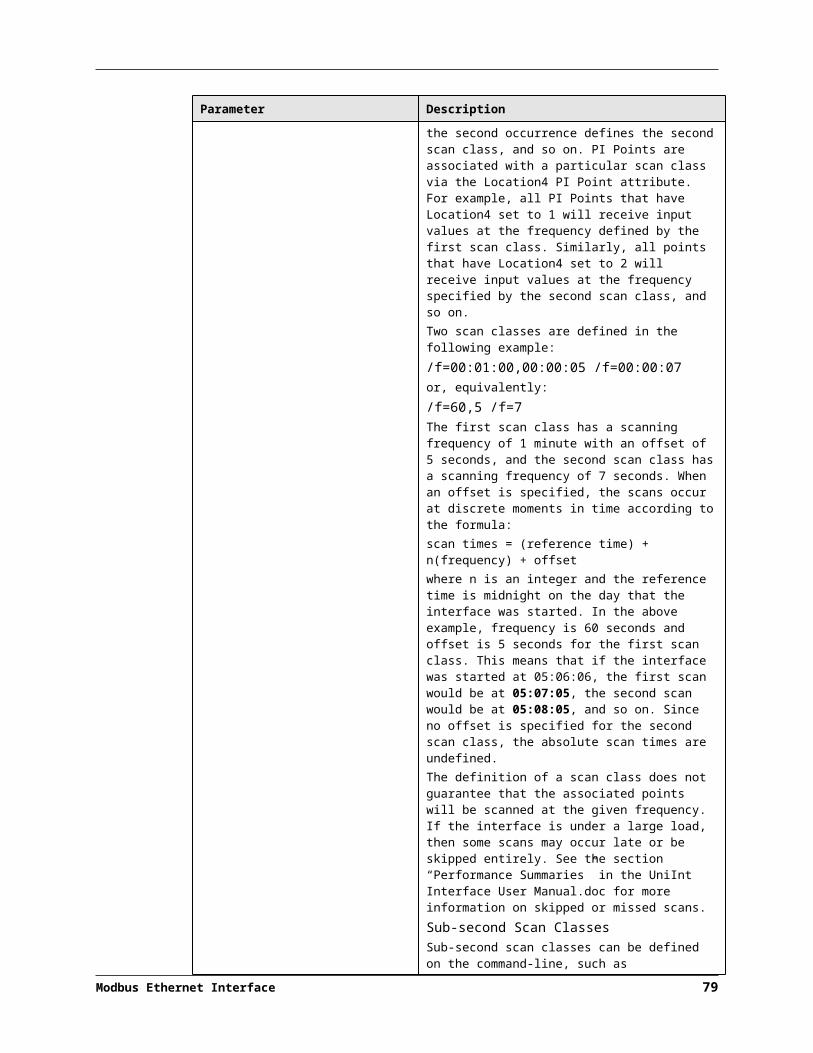
Chapter 11. UniInt Failover Configuration
Introduction
To minimize data loss during a single point of failure within a system, UniInt provides two failover schemas: (1) synchronization through the data source and (2) synchronization through a shared file. Synchronization through the data source is Phase 1, and synchronization through a shared file is Phase 2.
Phase 1 UniInt Failover uses the data source itself to synchronize failover operations and provides a hot failover, no data loss solution when a single point of failure occurs. For this option, the data source must be able to communicate with and provide data for two interfaces simultaneously. Additionally, the failover configuration requires the interface to support outputs.
Phase 2 UniInt Failover uses a shared file to synchronize failover operations and provides for hot, warm, or cold failover. The Phase 2 hot failover configuration provides a no data loss solution for a single point of failure similar to Phase 1. However, in warm and cold failover configurations, you can expect a small period of data loss during a single point of failure transition.
Note: This interface supports only Phase 2 failover.
You can also configure the UniInt interface level failover to send data to a High Availability (HA) PI Server collective. The collective provides redundant PI Servers to allow for the uninterrupted collection and presentation of PI time series data. In an HA configuration, PI Servers can be taken down for maintenance or repair. The HA PI Server collective is described in the PI Server Reference Guide.
When configured for UniInt failover, the interface routes all PI data through a state machine. The state machine determines whether to queue data or send it directly to PI depending on the current state of the interface. When the interface is in the active state, data sent through the interface gets routed directly to PI. In the backup state, data from the interface gets queued for a short period. Queued data in the backup interface ensures a no-data loss failover under normal circumstances for Phase 1 and for the hot failover configuration of Phase 2. The same algorithm of queuing events while in backup is used for output data.
Modbus Ethernet Interface 89

Quick OverviewThe Quick Overview below may be used to configure this Interface for failover. The failover configuration requires the two copies of the interface participating in failover be installed on different nodes. Users should verify non-failover interface operation as discussed in the Installation Checklist section of this manual prior to configuring the interface for failover operations. If you are not familiar with UniInt failover configuration, return to this section after reading the rest of the UniInt Failover Configuration section in detail. If a failure occurs at any step below, correct the error and start again at the beginning of step 6 Test in the table below. For the discussion below, the first copy of the interface configured and tested will be considered the primary interface and the second copy of the interface configured will be the backup interface.
Configuration One Data Source
Two Interfaces
Prerequisites Interface 1 is the Primary interface for collection of PI data from the data source.
Interface 2 is the Backup interface for collection of PI data from the data source.
You must set up a shared file.
Phase 2: The shared file must store data for five failover tags:
(1) Active ID.
(2) Heartbeat 1.
(3) Heartbeat 2.
(4) Device Status 1.
(5) Device Status 2.
Each interface must be configured with two required failover command line parameters: (1) its FailoverID number (/UFO_ID); (2) the FailoverID number of its Backup interface (/UFO_OtherID). You must also specify the name of the PI Server host for exceptions and PI tag updates.
All other configuration parameters for the two interfaces must be identical.
Modbus Ethernet Interface 90
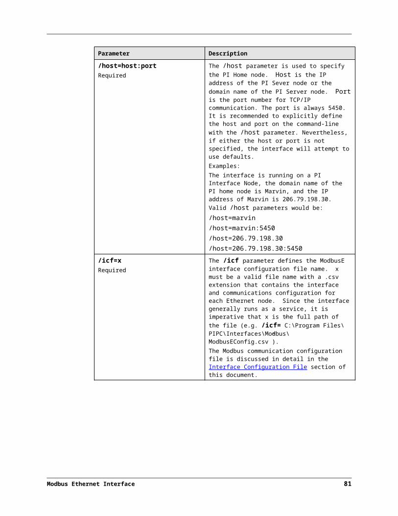
Synchronization through a Shared File (Phase 2)
Figure 1: Synchronization through a Shared File (Phase 2) Failover Architecture
The Phase 2 failover architecture is shown in Figure 2 which depicts a typical network setup including the path to the synchronization file located on a File Server (FileSvr). Other configurations may be supported and this figure is used only as an example for the following discussion.
For a more detailed explanation of this synchronization method, see Detailed Explanation of Synchronization through a Shared File (Phase 2)
Modbus Ethernet Interface 91

UniInt Failover Configuration
Configuring Synchronization through a Shared File (Phase 2)
Step Description
1. Verify non-failover interface operation as described in the Installation Checklist section of this manual
2. Configure the Shared FileChoose a location for the shared file. The file can reside on one of the interface nodes but OSIsoft strongly recommends that you put the file on a dedicated file server that has no other role in data collection.Setup a file share and make sure to assign the permissions so that both Primary and Backup interfaces have read/write access to the file.
3. Configure the interface parameters Use the Failover section of the Interface Configuration Utility (ICU) to enable failover and create two parameters for each interface: (1) a Failover ID number for the interface; and (2) the Failover ID number for its backup interface.The Failover ID for each interface must be unique and each interface must know the Failover ID of its backup interface.If the interface can perform using either Phase 1 or Phase 2 pick the Phase 2 radio button in the ICU.Select the synchronization File Path and File to use for Failover.Select the type of failover required (Cold, Warm, Hot). The choice depends on what types of failover the interface supports.Ensure that the user name assigned in the “Log on as:” parameter in the Service section of the ICU is a user that has read/write access to the folder where the shared file will reside.All other command line parameters for the primary and secondary interfaces must be identical.If you use a PI Collective, you must point the primary and secondary interfaces to different members of the collective by setting the SDK Member under the PI Host Information section of the ICU.[Option] Set the update rate for the heartbeat point if you need a value other than the default of 5000 milliseconds.
4. Configure the PI tagsConfigure five PI tags for the interface: the Active ID, Heartbeat 1, Heartbeat2, Device Status 1 and Device Status 2. You can also configure two state tags for monitoring the status of the interfaces.Do not confuse the failover Device status tags with the UniInt Health Device Status tags. The information in the two tags is similar, but the failover device status tags are integer values and the health device status tags are string values.
Tag ExDesc digitalset UniInt does not examine the remaining attributes, but the pointsource and location1 must match
ActiveID [UFO2_ACTIVEID]IF1_Heartbeat(IF-Node1) [UFO2_HEARTBEAT:#]IF2_Heartbeat(IF-Node2) [UFO2_HEARTBEAT:#]IF1_DeviceStatus(IF-Node1) [UFO2_DEVICESTAT:#]IF2_DeviceStatus(IF-Node2) [UFO2_DEVICESTAT:#]IF1_State(IF-Node1)
[UFO2_STATE:#] IF_State
92

Step Description
Tag ExDesc digitalset UniInt does not examine the remaining attributes, but the pointsource
IF2_State(IF-Node2) [UFO2_STATE:#] IF_State
5. Test the configuration. After configuring the shared file and the interface and PI tags, the interface should be ready to run.See Troubleshooting UniInt Failover for help resolving Failover issues.1. Start the primary interface interactively without buffering.2. Verify a successful interface start by reviewing the pipc.log file. The log
file will contain messages that indicate the failover state of the interface. A successful start with only a single interface copy running will be indicated by an informational message stating “UniInt failover: Interface in the “Primary” state and actively sending data to PI. Backup interface not available.” If the interface has failed to start, an error message will appear in the log file. For details relating to informational and error messages, refer to the Messages section below.
3. Verify data on the PI Server using available PI tools. The Active ID control tag on the PI Server must be set to the value of
the running copy of the interface as defined by the /UFO_ID startup command-line parameter.
The Heartbeat control tag on the PI Server must be changing values at a rate specified by the /UFO_Interval startup command-line parameter.
4. Stop the primary interface.5. Start the backup interface interactively without buffering. Notice that this copy
will become the primary because the other copy is stopped.6. Repeat steps 2, 3, and 4.7. Stop the backup interface.8. Start buffering.9. Start the primary interface interactively.10. Once the primary interface has successfully started and is collecting data,
start the backup interface interactively.11. Verify that both copies of the interface are running in a failover configuration.
Review the pipc.log file for the copy of the interface that was started first. The log file will contain messages that indicate the failover state of the interface. The state of this interface must have changed as indicated with an informational message stating “UniInt failover: Interface in the “Primary” state and actively sending data to PI. Backup interface available.” If the interface has not changed to this state, browse the log file for error messages. For details relating to informational and error messages, refer to the Messages section below.
Review the pipc.log file for the copy of the interface that was started last. The log file will contain messages that indicate the failover state of the interface. A successful start of the interface will be indicated by an informational message stating “UniInt failover: Interface in the “Backup” state.” If the interface has failed to start, an error message will appear in the log file. For details relating to informational and error messages, refer to the Messages section below.
Modbus Ethernet Interface 93

UniInt Failover Configuration
Step Description
12. Verify data on the PI Server using available PI tools. The Active ID control tag on the PI Server must be set to the value of
the running copy of the interface that was started first as defined by the /UFO_ID startup command-line parameter.
The Heartbeat control tags for both copies of the interface on the PI Server must be changing values at a rate specified by the /UFO_Interval startup command-line parameter or the scan class which the points have been built against.
13. Test Failover by stopping the primary interface.14. Verify the backup interface has assumed the role of primary by searching the
pipc.log file for a message indicating the backup interface has changed to the “UniInt failover: Interface in the “Primary” state and actively sending data to PI. Backup interface not available.” The backup interface is now considered primary and the previous primary interface is now backup.
15. Verify no loss of data in PI. There may be an overlap of data due to the queuing of data. However, there must be no data loss.
16. Start the backup interface. Once the primary interface detects a backup interface, the primary interface will now change state indicating “UniInt failover: Interface in the “Primary” state and actively sending data to PI. Backup interface available.” In the pipc.log file.
17. Verify the backup interface starts and assumes the role of backup. A successful start of the backup interface will be indicated by an informational message stating “UniInt failover: Interface in “Backup state.” Since this is the initial state of the interface, the informational message will be near the beginning of the start sequence of the pipc.log file.
18. Test failover with different failure scenarios (e.g. loss of PI connection for a single interface copy). UniInt failover guarantees no data loss with a single point of failure. Verify no data loss by checking the data in PI and on the data source.
19. Stop both copies of the interface, start buffering, start each interface as a service.
20. Verify data as stated above.21. To designate a specific interface as primary. Set the Active ID point on the
Data Source Server of the desired primary interface as defined by the /UFO_ID startup command-line parameter.
94

Configuring UniInt Failover through a Shared File (Phase 2)
Start-Up Parameters
Note: The /stopstat parameter is disabled If the interface is running in a UniInt failover configuration. Therefore, the digital state, digstate, will not be written to each PI Point when the interface is stopped. This prevents the digital state being written to PI Points while a redundant system is also writing data to the same PI Points. The /stopstat parameter is disabled even if there is only one interface active in the failover configuration.
The following table lists the start-up parameters used by UniInt Failover Phase 2. All the parameters are required except the /UFO_Interval startup parameter. See the table below for further explanation.
Parameter Required/Optional
Description Value/Default
/UFO_ID=# Required Failover ID for IF-Node1 This value must be different from the failover ID of IF-Node2.
Any positive, non-zero integer / 1
Required Failover ID for IF-Node2 This value must be different from the failover ID of IF-Node1.
Any positive, non-zero integer / 2
/UFO_OtherID=# Required Other Failover ID for IF-Node1 The value must be equal to the Failover ID configured for the interface on IF-Node2.
Same value as Failover ID for IF-Node2 / 2
Required Other Failover ID for IF-Node2 The value must be equal to the Failover ID configured for the interface on IF-Node1.
Same value as Failover ID for IF-Node1 / 1
/UFO_Sync=path/[filename]
Required for Phase 2 synchronization
The Failover File Synchronization Filepath and Optional Filename specify the path to the shared file used for failover synchronization and an optional filename used to specify a user defined filename in lieu of the default filename. The path to the shared file directory can be a fully qualified machine name and directory, a mapped drive letter, or a local path if the shared file is on one of the interface nodes. The path must be terminated by a slash ( / ) or backslash ( \ ) character. If no terminating slash is found, in the /UFO_Sync parameter, the interface interprets the final character string as an optional filename. The optional filename can be any valid filename. If the file does not
Any valid pathname / any valid filenameThe default filename is generated as executablename_pointsource_interfaceID.dat
Modbus Ethernet Interface 95

UniInt Failover Configuration
Parameter Required/Optional
Description Value/Default
exist, the first interface to start attempts to create the file.Note: If using the optional filename, do not supply a terminating slash or backslash character.If there are any spaces in the path or filename, the entire path and filename must be enclosed in quotes. Note: If you use the backslash and path separators and enclose the path in double quotes, the final backslash must be a double backslash (\\). Otherwise the closing double quote becomes part of the parameter instead of a parameter separator.Each node in the failover configuration must specify the same path and filename and must have read, write, and file creation rights to the shared directory specified by the path parameter. The service that the interface runs against must specify a valid logon user account under the “Log On” tab for the service properties.
/UFO_Type=type Required The Failover Type indicates which type of failover configuration the interface will run. The valid types for failover are HOT, WARM, and COLD configurations.If an interface does not supported the requested type of failover, the interface will shut down and log an error to the pipc.log file stating the requested failover type is not supported.
COLD|WARM|HOT / COLD
/UFO_Interval=# Optional Failover Update IntervalSpecifies the heartbeat Update Interval in milliseconds and must be the same on both interface computers.This is the rate at which UniInt updates the Failover Heartbeat tags as well as how often UniInt checks on the status of the other copy of the interface.
50 - 20000 / 1000
96

Parameter Required/Optional
Description Value/Default
/Host=server Required Host PI Server for Exceptions and PI tag updatesThe value of the /Host startup parameter depends on the PI Server configuration. If the PI Server is not part of a collective, the value of /Host must be identical on both interface computers.If the redundant interfaces are being configured to send data to a PI Server collective, the value of the /Host parameters on the different interface nodes should equal to different members of the collective.This parameter ensures that outputs continue to be sent to the Data Source if one of the PI Servers becomes unavailable for any reason.
For IF-Node1PrimaryPI / NoneFor IF-Node2SecondaryPI / None
Failover Control Points
The following table describes the points that are required to manage failover. In Phase 2 Failover, these points are located in a data file shared by the Primary and Backup interfaces.
OSIsoft recommends that you locate the shared file on a dedicated server that has no other role in data collection. This avoids potential resource contention and processing degradation if your system monitors a large number of data points at a high frequency.
Point Description Value / DefaultActiveID Monitored by the interfaces to determine which
interface is currently sending data to PI. ActiveID must be initialized so that when the interfaces read it for the first time, it is not an error.ActiveID can also be used to force failover. For example, if the current Primary is IF-Node 1 and ActiveID is 1, you can manually change ActiveID to 2. This causes the interface at IF-Node2 to transition to the primary role and the interface at IF-Node1 to transition to the backup role.
From 0 to the highest Interface Failover ID number / None)Updated by the redundant InterfacesCan be changed manually to initiate a manual failover
Heartbeat 1 Updated periodically by the interface on IF-Node1. The interface on IF-Node2 monitors this value to determine if the interface on IF-Node1 has become unresponsive.
Values range between 0 and 31 / NoneUpdated by the Interface on IF-Node1
Heartbeat 2 Updated periodically by the interface on IF-Node2. The interface on IF-Node1 monitors this value to determine if the interface on IF-Node2 has become unresponsive.
Values range between 0 and 31 / NoneUpdated by the Interface on IF-Node2
Modbus Ethernet Interface 97
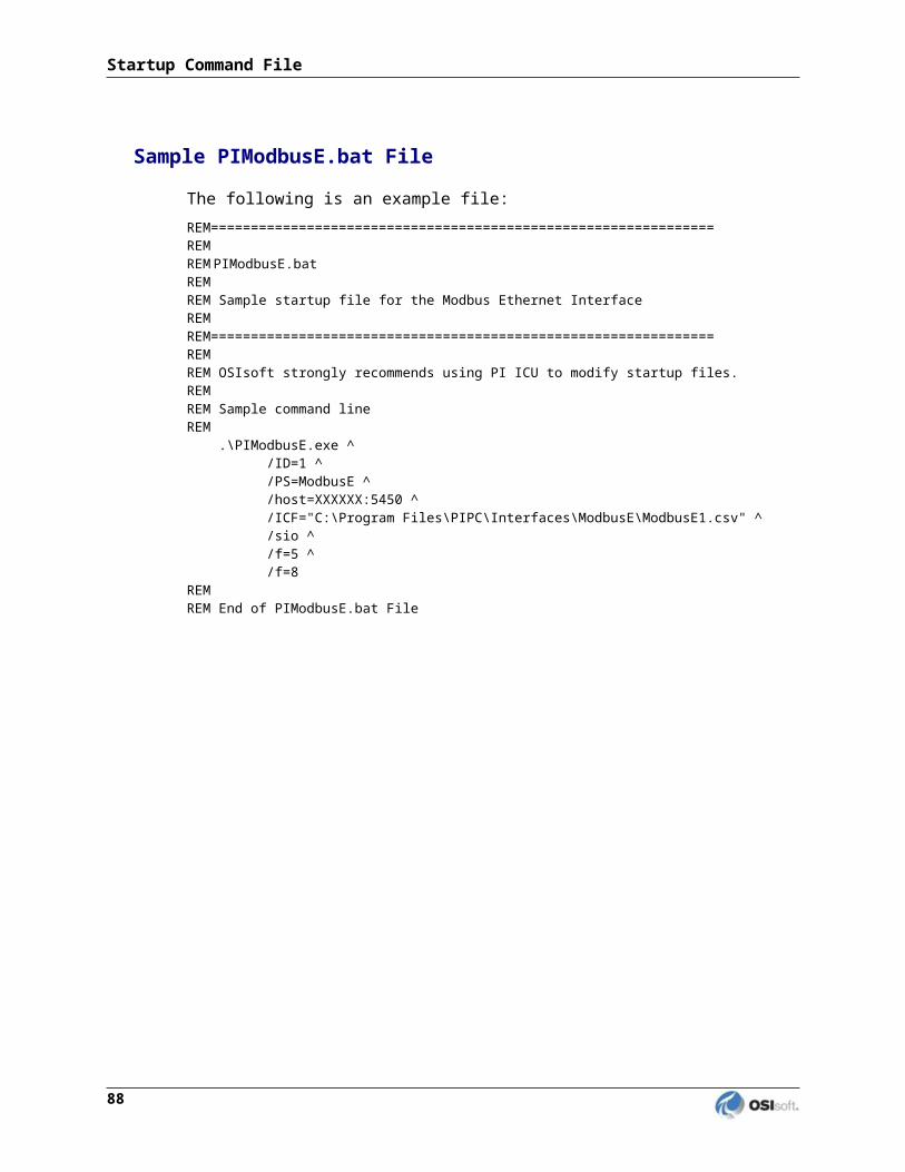
UniInt Failover Configuration
PI Tags
The following tables list the required UniInt Failover Control PI tags, the values they will receive, and descriptions.
Active_ID Tag Configuration
Attributes ActiveID
Tag <Intf>_ActiveIDExDesc [UFO2_ActiveID]
Location1 Match # in /id=#Location5 Optional, Time in min to wait for backup
to collect data before failing over.
Point Source Match x in /ps=xPoint Type Int32
Shutdown 0
Step 1
Heartbeat and Device Status Tag Configuration
Attribute Heartbeat 1 Heartbeat 2 DeviceStatus 1 DeviceStatus 2Tag <HB1> <HB2> <DS1> <DS2>
ExDesc[UFO2_Heartbeat:#]Match # in /UFO_ID=#
[UFO2_Heartbeat:#]Match # in /UFO_OtherID=#
[UFO2_DeviceStat:#]Match # in /UFO_ID=#
[UFO2_DeviceStat:#]Match # in /UFO_OtherID=#
Location1 Match # in /id=# Match # in /id=# Match # in /id=# Match # in /id=#Location5 Optional, Time in
min to wait for backup to collect data before failing over.
Optional, Time in min to wait for backup to collect data before failing over.
Optional, Time in min to wait for backup to collect data before failing over.
Optional, Time in min to wait for backup to collect data before failing over.
Point Source
Match x in /ps=x Match x in /ps=x Match x in /ps=x Match x in /ps=x
Point Type int32 int32 int32 int32
Shutdown 0 0 0 0
Step 1 1 1 1
Interface State Tag Configuration
Attribute Primary Backup
Tag <Tagname1> <Tagname2>
DigitalSet UFO_State UFO_State
ExDesc [UFO2_State:#](Match /UFO_ID=# on primary node)
[UFO2_State:#](Match /UFO_ID=# on backup node)
Location1 Match # in /id=# Same as for Primary node
PointSource Match x in /ps=x Same as for Primary node
PointType digital digital
Shutdown 0 0
Step 1 1
98

The following table describes the extended descriptor for the above PI tags in more detail.
PI Tag ExDesc Required / Optional
Description Value
[UFO2_ACTIVEID] Required Active ID tagThe ExDesc must start with the case sensitive string: [UFO2_ACTIVEID]. The pointsource must match the interfaces’ point source. Location1 must match the ID for the interfaces. Location5 is the COLD failover retry interval in minutes. This can be used to specify how long before an interface retries to connect to the device in a COLD failover configuration. (See the description of COLD failover retry interval for a detailed explanation.)
0 - highest Interface Failover IDUpdated by the redundant Interfaces
[UFO2_HEARTBEAT:#](IF-Node1)
Required Heartbeat 1 TagThe ExDesc must start with the case sensitive string: [UFO2_HEARTBEAT:#]The number following the colon (:) must be the Failover ID for the interface running on IF-Node1. The pointsource must match the interfaces’ point source. Location1 must match the ID for the interfaces.
0 - 31 / NoneUpdated by the Interface on IF-Node1
[UFO2_HEARTBEAT:#](IF-Node2)
Required Heartbeat 2 TagThe ExDesc must start with the case sensitive string: [UFO2_HEARTBEAT:#]The number following the colon (:) must be the Failover ID for the interface running on IF-Node2. The pointsource must match the interfaces’ point source. Location1 must match the id for the interfaces.
0 - 31 / NoneUpdated by the Interface on IF-Node2
Modbus Ethernet Interface 99

UniInt Failover Configuration
PI Tag ExDesc Required / Optional
Description Value
[UFO2_DEVICESTAT :#](IF-Node1)
Required Device Status 1 TagThe ExDesc must start with the case sensitive string: [UFO2_HEARTBEAT:#]The value following the colon (:) must be the Failover ID for the interface running on IF-Node1The pointsource must match the interfaces’ point source. Location1 must match the id for the interfaces.A lower value is a better status and the interface with the lower status will attempt to become the primary interface.The failover 1 device status tag is very similar to the UniInt Health Device Status tag except the data written to this tag are integer values. A value of 0 is good and a value of 99 is OFF. Any value between these two extremes may result in a failover. The interface client code updates these values when the health device status tag is updated.
0 - 99 / NoneUpdated by the Interface on IF-Node1
[UFO2_DEVICESTAT :#](IF-Node2)
Required Device Status 2 TagThe ExDesc must start with the case sensitive string: [UFO2_HEARTBEAT:#]The number following the colon (:) must be the Failover ID for the interface running on IF-Node2The pointsource must match the interfaces’ point source. Location1 must match the ID for the interfaces. A lower value is a better status and the interface with the lower status will attempt to become the primary interface.
0 - 99 / NoneUpdated by the Interface on IF-Node2
[UFO2_STATE:#](IF-Node1)
Optional State 1 TagThe ExDesc must start with the case sensitive string: [UFO2_STATE:#]The number following the colon (:) must be the Failover ID for the interface running on IF-Node1The failover state tag is recommended.The failover state tags are digital tags assigned to a digital state set with the following values.0 = Off: The interface has been shut down.1 = Backup No Data Source: The
0 - 5 / NoneNormally updated by the Interface currently in the primary role.
100

PI Tag ExDesc Required / Optional
Description Value
interface is running but cannot communicate with the data source.2 = Backup No PI Connection: The interface is running and connected to the data source but has lost its communication to the PI Server.3 = Backup: The interface is running and collecting data normally and is ready to take over as primary if the primary interface shuts down or experiences problems.4 = Transition: The interface stays in this state for only a short period of time. The transition period prevents thrashing when more than one interface attempts to assume the role of primary interface.5 = Primary: The interface is running, collecting data and sending the data to PI.
[UFO2_STATE:#](IF-Node2)
Optional State 2 Tag The ExDesc must start with the case sensitive string: [UFO2_STATE:#]The number following the colon (:) must be the Failover ID for the interface running on IF-Node2The failover state tag is recommended.
Normally updated by the Interface currently in the Primary state.Values range between 0 and 5. See description of State 1 tag.
Modbus Ethernet Interface 101

UniInt Failover Configuration
Detailed Explanation of Synchronization through a Shared File (Phase 2)
In a shared file failover configuration, there is no direct failover control information passed between the data source and the interface. This failover scheme uses five PI tags to control failover operation, and all failover communication between primary and backup interfaces passes through a shared data file.
Once the interface is configured and running, the ability to read or write to the PI tags is not required for the proper operation of failover. This solution does not require a connection to the PI Server after initial startup because the control point data are set and monitored in the shared file. However, the PI tag values are sent to the PI Server so that you can monitor them with standard OSIsoft client tools.
You can force manual failover by changing the ActiveID on the data source to the backup failover ID.
The figure above shows a typical network setup in the normal or steady state. The solid magenta lines show the data path from the interface nodes to the shared file used for failover synchronization. The shared file can be located anywhere in the network as long as both interface nodes can read, write, and create the necessary file on the shared file machine. OSIsoft strongly recommends that you put the file on a dedicated file server that has no other role in the collection of data.
The major difference between synchronizing the interfaces through the data source (Phase 1) and synchronizing the interfaces through the shared file (Phase 2) is where the control data is located. When synchronizing through the data source, the control data is acquired directly from the data source. We assume that if the primary interface cannot read the failover control
102

points, then it cannot read any other data. There is no need for a backup communications path between the control data and the interface.
When synchronizing through a shared file, however, we cannot assume that loss of control information from the shared file implies that the primary interface is down. We must account for the possible loss of the path to the shared file itself and provide an alternate control path to determine the status of the primary interface. For this reason, if the shared file is unreachable for any reason, the interfaces use the PI Server as an alternate path to pass control data.
When the backup interface does not receive updates from the shared file, it cannot tell definitively why the primary is not updating the file, whether the path to the shared file is down, whether the path to the data source is down, or whether the interface itself is having problems. To resolve this uncertainty, the backup interface uses the path to the PI Server to determine the status of the primary interface. If the primary interface is still communicating with the PI Server, than failover to the backup is not required. However, if the primary interface is not posting data to the PI Server, then the backup must initiate failover operations.
The primary interface also monitors the connection with the shared file to maintain the integrity of the failover configuration. If the primary interface can read and write to the shared file with no errors but the backup control information is not changing, then the backup is experiencing some error condition. To determine exactly where the problem exists, the primary interface uses the path to PI to establish the status of the backup interface. For example, if the backup interface controls indicate that it has been shutdown, it may have been restarted and is now experiencing errors reading and writing to the shared file. Both primary and backup interfaces must always check their status through PI to determine if one or the other is not updating the shared file and why.
Steady State Operation
Steady state operation is considered the normal operating condition. In this state, the primary interface is actively collecting data and sending its data to PI. The primary interface is also updating its heartbeat value; monitoring the heartbeat value for the backup interface, checking the active ID value, and checking the device status for the backup interface every failover update interval on the shared file. Likewise, the backup interface is updating its heartbeat value; monitoring the heartbeat value for the primary interface, checking the active ID value, and checking the device status for the primary interface every failover update interval on the shared file. As long as the heartbeat value for the primary interface indicates that it is operating properly, the ActiveID has not changed, and the device status on the primary interface is good, the backup interface will continue in this mode of operation.
An interface configured for hot failover will have the backup interface actively collecting and queuing data but not sending that data to PI. An interface for warm failover in the backup role is not actively collecting data from the data source even though it may be configured with PI tags and may even have a good connection to the data source. An interface configured for cold failover in the backup role is not connected to the data source and upon initial startup will not have configured PI tags.
The interaction between the interface and the shared file is fundamental to failover. The discussion that follows only refers to the data written to the shared file. However, every value written to the shared file is echoed to the tags on the PI Server. Updating of the tags on the PI Server is assumed to take place unless communication with the PI Server is interrupted. The updates to the PI Server will be buffered by bufserv or BufSS in this case.
Modbus Ethernet Interface 103

UniInt Failover Configuration
In a hot failover configuration, each interface participating in the failover solution will queue three failover intervals worth of data to prevent any data loss. When a failover occurs, there may be a period of overlapping data for up to 3 intervals. The exact amount of overlap is determined by the timing and the cause of the failover and may be different every time. Using the default update interval of 5 seconds will result in overlapping data between 0 and 15 seconds. The no data loss claim for hot failover is based on a single point of failure. If both interfaces have trouble collecting data for the same period of time, data will be lost during that time.
As mentioned above, each interface has its own heartbeat value. In normal operation, the Heartbeat value on the shared file is incremented by UniInt from 1 - 15 and then wraps around to a value of 1 again. UniInt increments the heartbeat value on the shared file every failover update interval. The default failover update interval is 5 seconds. UniInt also reads the heartbeat value for the other interface copy participating in failover every failover update interval. If the connection to the PI Server is lost, the value of the heartbeat will be incremented from 17 - 31 and then wrap around to a value of 17 again. Once the connection to the PI Server is restored, the heartbeat values will revert back to the 1 - 15 range. During a normal shutdown process, the heartbeat value will be set to zero.
During steady state, the ActiveID will equal the value of the failover ID of the primary interface. This value is set by UniInt when the interface enters the primary state and is not updated again by the primary interface until it shuts down gracefully. During shutdown, the primary interface will set the ActiveID to zero before shutting down. The backup interface has the ability to assume control as primary even if the current primary is not experiencing problems. This can be accomplished by setting the ActiveID tag on the PI Server to the ActiveID of the desired interface copy.
As previously mentioned, in a hot failover configuration the backup interface actively collects data but does not send its data to PI. To eliminate any data loss during a failover, the backup interface queues data in memory for three failover update intervals. The data in the queue is continuously updated to contain the most recent data. Data older than three update intervals is discarded if the primary interface is in a good status as determined by the backup. If the backup interface transitions to the primary, it will have data in its queue to send to PI. This queued data is sent to PI using the same function calls that would have been used had the interface been in a primary state when the function call was received from UniInt. If UniInt receives data without a timestamp, the primary copy uses the current PI time to timestamp data sent to PI. Likewise, the backup copy timestamps data it receives without a timestamp with the current PI time before queuing its data. This preserves the accuracy of the timestamps.
104

Failover Configuration Using PI ICU
The use of the PI ICU is the recommended and safest method for configuring the Interface for UniInt failover. With the exception of the notes described in this section, the Interface shall be configured with the PI ICU as described in the “Configuring the Interface with the PI ICU” section of this manual.
Note: With the exception of the /UFO_ID and /UFO_OtherID startup command-line parameters, the UniInt failover scheme requires that both copies of the interface have identical startup command files. This requirement causes the PI ICU to produce a message when creating the second copy of the interface stating that the “PS/ID combo already in use by the interface” as shown in Figure 2 below. Ignore this message and click the Add button.
Create the Interface Instance with PI ICU
If the interface does not already exist in the ICU it must first be created. The procedure for doing this is the same as for non-failover interfaces. When configuring the second instance for UniInt Failover the Point Source and Interface ID will be in yellow and a message will be displayed saying this is already in use. This should be ignored.
Figure 2: PI ICU configuration screen shows that the “PS/ID combo is already in use by the interface.” The user must ignore the yellow boxes, which indicate errors, and click the Add button to configure the interface for failover.
Modbus Ethernet Interface 105

UniInt Failover Configuration
Configuring the UniInt Failover Startup Parameters with PI ICU
There are three interface startup parameters that control UniInt failover: /UFO_ID, /UFO_OtherID, and /UFO_Interval. The UFO stands for UniInt Failover. The /UFO_ID and /UFO_OtherID parameters are required for the interface to operate in a failover configuration, but the /UFO_Interval is optional. Each of these parameters is described in detail in Configuring UniInt Failover through a Shared File (Phase 2)section and Start-Up Parameters
Figure 3: The figure above illustrates the PI ICU failover configuration screen showing the UniInt failover startup parameters (Phase 2). This copy of the interface defines its Failover ID as 2 (/UFO_ID=2) and the other interfaces Failover ID as 1 (/UFO_OtherID=1). The other failover interface copy must define its Failover ID as 1 (/UFO_ID=1) and the other interface Failover ID as 2 (/UFO_OtherID=2) in its ICU failover configuration screen. It also defines the location and name of the synchronization file as well as the type of failover as COLD.
Creating the Failover State Digital State Set
The UFO_State digital state set is used in conjunction with the failover state digital tag. If the UFO_State digital state set has not been created yet, it can be using either the Failover page of the ICU (1.4.1.0 or greater) or the Digital States plug-in in the SMT 3 Utility (3.0.0.7 or greater).
106

Using the PI ICU Utility to create Digital State Set
To use the UniInt Failover page to create the UFO_State digital state set right click on any of the failover tags in the tag list and then select the “Create UFO_State Digital Set on Server XXXXXX…”, where XXXXXX is the PI Server where the points will be or are create on.
This choice will be grayed out if the UFO_State digital state set is already created on the XXXXXX PI Server.
Using the PI SMT 3 Utility to create Digital State Set
Optionally the “Export UFO_State Digital Set (.csv) can be selected to create a comma separated file to be imported via the System Manangement Tools (SMT3) (version 3.0.0.7 or higher) or use the UniInt_Failover_DigitalSet_UFO_State.csv file included in the installation kit.
The procedure below outlines the steps necessary to create a digital set on a PI Sever using the “Import from File” function found in the SMT3 application. The procedure assumes the user has a basic understanding of the SMT3 application.
1. Open the SMT3 application.
2. Select the appropriate PI Server from the PI Servers window. If the desired server is not listed, add it using the PI Connection Manager. A view of the SMT application is shown in Figure 4 below.
3. From the System Management Plug-Ins window, select Points then Digital States. A list of available digital state sets will be displayed in the main window for the selected PI Server. Refer to Figure 4 below.
4. In the main window, right click on the desired server and select the “Import from File” option. Refer to Figure 4 below.
Modbus Ethernet Interface 107

UniInt Failover Configuration
Figure 4: PI SMT application configured to import a digital state set file. The PI Servers window shows the “localhost” PI Server selected along with the System Management Plug-Ins window showing the Digital States Plug-In as being selected. The digital state set file can now be imported by selecting the Import from File option for the localhost.
5. Navigate to and select the UniInt_Failover_DigitalSet_UFO_State.csv file for import using the Browse icon on the display. Select the desired Overwrite Options. Click on the OK button. Refer to Figure 5 below.
Figure 5: PI SMT application Import Digital Set(s) window. This view shows the UniInt_Failover_DigitalSet_UFO_State.csv file as being selected for import. Select the desired Overwrite Options by choosing the appropriate radio button.
108

6. Navigate to and select the UniInt_Failover_DigitalSet_UFO_State.csv file for import using the Browse icon on the display. Select the desired Overwrite Options. Click on the OK button. Refer to Figure 5 above.
7. The UFO_State digital set is created as shown in Figure 6 below.
Figure 6: The PI SMT application showing the UFO_State digital set created on the “localhost” PI Server.
Modbus Ethernet Interface 109

UniInt Failover Configuration
Creating the UniInt Failover Control and Failover State Tags (Phase 2)
The ICU can be used to create the UniInt Failover Control and State Tags.
To use the ICU Failover page to create these tags simply right click any of the failover tags in the tag list and select the “Create all points (UFO Phase 2)” menu item.
If this menu choice is grayed out it is because the UFO_State digital state set has not been created on the Server yet. There is a menu choice “Create UFO_State Digitial Set on Server xxxxxxx…” which can be used to create that digital state set. Once this has been done then the “Create all points (UFO Phase2) should be available.
Once the failover control and failover state tags have been created the Failover page of the ICU should look similar to the illustration below.
110

Chapter 12. Interface Node Clock
Make sure that the time and time zone settings on the computer are correct. To confirm, run the Date/Time applet located in the Windows Control Panel. If the locale where the Interface Node resides observes Daylight Saving Time, check the “Automatically adjust clock for daylight saving changes” box. For example,
In addition, make sure that the TZ environment variable is not defined. All of the currently defined environment variables can be viewed by opening a Command Prompt window and typing set. That is,C:> set
Confirm that TZ is not in the resulting list. If it is, run the System applet of the Control Panel, click the “Environment Variables” button under the Advanced Tab, and remove TZ from the list of environment variables.
Modbus Ethernet Interface 111

Chapter 13. Security
Windows
The PI Firewall Database and the PI Proxy Database must be configured so that the interface is allowed to write data to the PI Server. See “Modifying the Firewall Database” and “Modifying the Proxy Database” in the PI Server manuals.
Note that the Trust Database, which is maintained by the Base Subsystem, replaces the Proxy Database used prior to PI version 3.3. The Trust Database maintains all the functionality of the proxy mechanism while being more secure.
See “Trust Login Security” in the chapter “Managing Security” of the PI Server System Management Guide.
If the interface cannot write data to the PI Server because it has insufficient privileges, a -10401 error will be reported in the pipc.log file. If the interface cannot send data to a PI2 Serve, it writes a -999 error. See the section Appendix A: Error and Informational Messages for additional information on error messaging.
PI Server v3.3 and Higher
Security configuration using piconfigFor PI Server v3.3 and higher, the following example demonstrates how to edit the PI Trust table:
C:\PI\adm> piconfig@table pitrust@mode create@istr Trust,IPAddr,NetMask,PIUsera_trust_name,192.168.100.11,255.255.255.255,piadmin@quit
For the above,
Trust: An arbitrary name for the trust table entry; in the above example,a_trust_name
IPAddr: the IP Address of the computer running the Interface; in the above example,192.168.100.11
NetMask: the network mask; 255.255.255.255 specifies an exact match with IPAddr
PIUser: the PI user the Interface to be entrusted as; piadmin is usually an appropriate user
Modbus Ethernet Interface 113

Security Configuring using Trust EditorThe Trust Editor plug-in for PI System Management Tools 3.x may also be used to edit the PI Trust table.
See the PI System Management chapter in the PI Server manual for more details on security configuration.
PI Server v3.2For PI Server v3.2, the following example demonstrates how to edit the PI Proxy table:
C:\PI\adm> piconfig@table pi_gen,piproxy@mode create@istr host,proxyaccountpiapimachine,piadmin@quit
In place of piapimachine, put the name of the PI Interface node as it is seen by PI Server.
Modbus Ethernet Interface 114

Chapter 14. Starting / Stopping the Interface
This section describes starting and stopping the Interface once it has been installed as a service. See the UniInt Interface User Manual to run the Interface interactively.
Starting Interface as a Service
If the Interface was installed as service, it can be started from PI ICU, the Services control panel or with the command:PIModbusE.exe -start
To start the interface service with PI ICU, use the button on the PI ICU toolbar.
A message will inform the user of the status of the interface service. Even if the message indicates that the service has started successfully, double check through the Services control panel applet. Services may terminate immediately after startup for a variety of reasons, and one typical reason is that the service is not able to find the command-line parameters in the associated .bat file. Verify that the root name of the .bat file and the .exe file are the same, and that the .bat file and the .exe file are in the same directory. Further troubleshooting of services might require consulting the pipc.log file, Windows Event Viewer, or other sources of log messages. See the section Appendix A: Error and Informational Messages for additional information.
Stopping Interface Running as a Service
If the Interface was installed as service, it can be stopped at any time from PI ICU, the Services control panel or with the command:PIModbusE.exe -stop
The service can be removed by:PIModbusE.exe -remove
To stop the interface service with PI ICU, use the button on the PI ICU toolbar.
Modbus Ethernet Interface 115

Chapter 15. Buffering
Buffering refers to an Interface Node’s ability to temporarily store the data that interfaces collect and to forward these data to the appropriate PI Servers. OSIsoft strongly recommends that you enable buffering on your Interface Nodes. Otherwise, if the Interface Node stops communicating with the PI Server, you lose the data that your interfaces collect.
The PI SDK installation kit installs two buffering applications: the PI Buffer Subsystem (PIBufss) and the PI API Buffer Server (Bufserv). PIBufss and Bufserv are mutually exclusive; that is, on a particular computer, you can run only one of them at any given time.
If you have PI Servers that are part of a PI Collective, PIBufss supports n-way buffering. N-way buffering refers to the ability of a buffering application to send the same data to each of the PI Servers in a PI Collective. (Bufserv also supports n-way buffering, but OSIsoft recommends that you run PIBufss instead.)
Which Buffering Application to Use
You should use PIBufss whenever possible because it offers better throughput than Bufserv. In addition, if the interfaces on an Interface Node are sending data to a PI Collective, PIBufss guarantees identical data in the archive records of all the PI Servers that are part of that collective.
You can use PIBufss only under the following conditions:
the PI Server version is at least 3.4.375.x; and
all of the interfaces running on the Interface Node send data to the same PI Server or to the same PI Collective.
If any of the following scenarios apply, you must use Bufserv:
the PI Server version is earlier than 3.4.375.x; or
the Interface node runs multiple interfaces, and these interfaces send data to multiple PI Servers that are not part of a single PI Collective.
If an Interface Node runs multiple interfaces, and these interfaces send data to two or more PI Collectives, then neither PIBufss nor Bufserv is appropriate. The reason is that PIBufss and Bufserv can buffer data only to a single collective. If you need to buffer to more than one PI Collective, you need to use two or more Interface Nodes to run your interfaces.
It is technically possible to run Bufserv on the PI Server Node. However, OSIsoft does not recommend this configuration.
Modbus Ethernet Interface 117

How Buffering Works
A complete technical description of PIBufss and Bufserv is beyond the scope of this document. However, the following paragraphs provide some insights on how buffering works.
When an Interface Node has Buffering enabled, the buffering application (PIBufss or Bufserv) connects to the PI Server. It also creates shared memory storage.
When an interface program makes a PI API function call that writes data to the PI Server (for example, pisn_sendexceptionqx()), the PI API checks whether buffering is enabled. If it is, these data writing functions do not send the interface data to the PI Server. Instead, they write the data to the shared memory storage that the buffering application created.
The buffering application (either Bufserv or PIBufss) in turn
reads the data in shared memory, and
if a connection to the PI Server exists, sends the data to the PI Server; or
if there is no connection to the PI Server, continues to store the data in shared memory (if shared memory storage is available) or writes the data to disk (if shared memory storage is full).
When the buffering application re-establishes connection to the PI Server, it writes to the PI Server the interface data contained in both shared memory storage and disk.
(Before sending data to the PI Server, PIBufss performs further tasks such data validation and data compression, but the description of these tasks is beyond the scope of this document.)
When PIBufss writes interface data to disk, it writes to multiple files. The names of these buffering files are PIBUFQ_*.DAT.
When Bufserv writes interface data to disk, it writes to a single file. The name of its buffering file is APIBUF.DAT.
As a previous paragraph indicates, PIBufss and Bufserv create shared memory storage at startup. These memory buffers must be large enough to accommodate the data that an interface collects during a single scan. Otherwise, the interface may fail to write all its collected data to the memory buffers, resulting in data loss. The buffering configuration section of this chapter provides guidelines for sizing these memory buffers.
When buffering is enabled, it affects the entire Interface Node. That is, you do not have a scenario whereby the buffering application buffers data for one interface running on an Interface Node but not for another interface running on the same Interface Node.
Buffering and PI Server Security
After you enable buffering, it is the buffering application—and not the interface program—that writes data to the PI Server. If the PI Server’s trust table contains a trust entry that allows all applications on an Interface Node to write data, then the buffering application is able write data to the PI Server.
However, if the PI Server contains an interface-specific PI Trust entry that allows a particular interface program to write data, you must have a PI Trust entry specific to buffering. The following are the appropriate entries for the Application Name field of a PI Trust entry:
Modbus Ethernet Interface 118

Buffering Application Application Name field for PI TrustPI Buffer Subsystem PIBufss.exe
PI API Buffer Server APIBE (if the PI API is using 4 character process names)APIBUF (if the PI API is using 8 character process names)
To use a process name greater than 4 characters in length for a trust application name, use the LONGAPPNAME=1 in the PIClient.ini file.
Enabling Buffering on an Interface Node with the ICU
The ICU allows you to select either PIBufss or Bufserv as the buffering application for your Interface Node. Run the ICU and select Tools > Buffering.
Choose Buffer Type
To select PIBufss as the buffering application, choose Enable buffering with PI Buffer Subsystem.
To select Bufserv as the buffering application, choose Enable buffering with API Buffer Server.
If a warning message such as the following appears, click Yes.
Modbus Ethernet Interface 119

Buffering
Buffering Settings
There are a number of settings that affect the operation of PIBufss and Bufserv. The Buffering Settings section allows you to set these parameters. If you do not enter values for these parameters, PIBufss and Bufserv use default values.
PIBufssFor PIBufss, the paragraphs below describe the settings that may require user intervention. Please contact OSIsoft Technical Support for assistance in further optimizing these and all remaining settings.
Primary and Secondary Memory Buffer Size (Bytes)This is a key parameter for buffering performance. The sum of these two memory buffer sizes must be large enough to accommodate the data that an interface collects during a single scan. A typical event with a Float32 point type requires about 25 bytes. If an interface writes data to 5,000 points, it can potentially send 125,000 bytes (25 * 5000) of data in one scan. As a result, the size of each memory buffer should be 62,500 bytes.
The default value of these memory buffers is 32,768 bytes. OSIsoft recommends that these two memory buffer sizes should be increased to the maximum of 2000000 for the best buffering performance.
Send rate (milliseconds)Send rate is the time in milliseconds that PIBufss waits between sending up to the Maximum transfer objects (described below) to the PI Server. The default value is 100. The valid range is 0 to 2,000,000.
120

Maximum transfer objectsMaximum transfer objects is the maximum number of events that PIBufss sends between each Send rate pause. The default value is 500. The valid range is 1 to 2,000,000.
Event Queue File Size (Mbytes)This is the size of the event queue files. PIBufss stores the buffered data to these files. The default value is 32. The range is 8 to 131072 (8 to 128 Gbytes). Please see the section entitled, “Queue File Sizing” in the PIBufss.chm file for details on how to appropriately size the event queue files.
Event Queue PathThis is the location of the event queue file. The default value is [PIHOME]\DAT.
For optimal performance and reliability, OSIsoft recommends that you place the PIBufss event queue files on a different drive/controller from the system drive and the drive with the Windows paging file. (By default, these two drives are the same.)
BufservFor Bufserv, the paragraphs below describe the settings that may require user intervention. Please contact OSIsoft Technical Support for assistance in further optimizing these and all remaining settings.
Maximum buffer file size (KB)This is the maximum size of the buffer file ([PIHOME]\DAT\APIBUF.DAT). When Bufserv cannot communicate with the PI Server, it writes and appends data to this file. When the buffer file reaches this maximum size, Bufserv discards data.
The default value is 2,000,000 KB, which is about 2 GB. The range is from 1 to 2,000,000.
Modbus Ethernet Interface 121

Buffering
Primary and Secondary Memory Buffer Size (Bytes)This is a key parameter for buffering performance. The sum of these two memory buffer sizes must be large enough to accommodate the data that an interface collects during a single scan. A typical event with a Float32 point type requires about 25 bytes. If an interface writes data to 5,000 points, it can potentially send 125,000 bytes (25 * 5000) of data in one scan. As a result, the size of each memory buffer should be 62,500 bytes.
The default value of these memory buffers is 32,768 bytes. OSIsoft recommends that these two memory buffer sizes should be increased to the maximum of 2000000 for the best buffering performance.
Send rate (milliseconds)Send rate is the time in milliseconds that Bufserv waits between sending up to the Maximum transfer objects (described below) to the PI Server. The default value is 100. The valid range is 0 to 2,000,000.
Maximum transfer objectsMax transfer objects is the maximum number of events that Bufserv sends between each Send rate pause. The default value is 500. The valid range is 1 to 2,000,000.
Buffered Servers
The Buffered Servers section allows you to define the PI Servers or PI Collective that the buffering application writes data.
PIBufssPIBufss buffers data only to a single PI Server or a PI Collective. Select the PI Server or the PI Collective from the Buffering to collective/server drop down list box.
The following screen shows that PIBufss is configured to write data to a standalone PI Server named starlight. Notice that the Replicate data to all collective member nodes check box is disabled because this PI Server is not part of a collective. (PIBufss automatically detects whether a PI Server is part of a collective.)
122

The following screen shows that PIBufss is configured to write data to a PI Collective named admiral. By default, PIBufss replicates data to all collective members. That is, it provides n-way buffering.
You can override this option by not checking the Replicate data to all collective member nodes check box. Then, uncheck (or check) the PI Server collective members as desired.
Modbus Ethernet Interface 123

Buffering
BufservBufserv buffers data to a standalone PI Server, or to multiple standalone PI Servers. (If you want to buffer to multiple PI Servers that are part of a PI Collective, you should use PIBufss.)
If the PI Server to which you want Bufserv to buffer data is not in the Server list, enter its name in the Add a server box and click the Add Server button. This PI Server name must be identical to the API Hostname entry:
The following screen shows that Bufserv is configured to write to a standalone PI Server named etamp390. You use this configuration when all the interfaces on the Interface Node write data to etamp390.
The following screen shows that Bufserv is configured to write to two standalone PI Servers, one named etamp390 and the other one named starlight. You use this configuration when some of the interfaces on the Interface Node write data to etamp390 and some write to starlight.
124

Installing Buffering as a Service
Both the PIBufss and Bufserv applications run as a Service.
PI Buffer Subsystem ServiceUse the PI Buffer Subsystem Service page to configure PIBufss as a Service. This page also allows you to start and stop the PIBufss service.
PIBufss does not require the logon rights of the local administrator account. It is sufficient to use the LocalSystem account instead. Although the screen below shows asterisks for the LocalSystem password, this account does not have a password.
Modbus Ethernet Interface 125

Buffering
API Buffer Server ServiceUse the API Buffer Server Service page to configure Bufserv as a Service. This page also allows you to start and stop the Bufserv Service
Bufserv version 1.6 and later does not require the logon rights of the local administrator account. It is sufficient to use the LocalSystem account instead. Although the screen below shows asterisks for the LocalSystem password, this account does not have a password.
126

Modbus Ethernet Interface 127

Chapter 16. Interface Diagnostics Configuration
The Interface Point Configuration chapter provides information on building PI points for collecting data from the device. This chapter describes the configuration of points related to interface diagnostics.
Note: The procedure for configuring interface diagnostics is not specific to this Interface. Thus, for simplicity, the instructions and screenshots that follow refer to an interface named ModbusE.
Some of the points that follow refer to a “performance summary interval”. This interval is 8 hours by default. You can change this parameter via the Scan performance summary box in the UniInt - Debug parameter category pane:
Scan Class Performance Points
A Scan Class Performance Point measures the amount of time (in seconds) that this Interface takes to complete a scan. The Interface writes this scan completion time to millisecond resolution. Scan completion times close to 0 indicate that the Interface is performing optimally. Conversely, long scan completion times indicate an increased risk of missed or skipped scans. To prevent missed or skipped scans, you should distribute the data collection points among several scan classes.
Modbus Ethernet Interface 129

You configure one Scan Class Performance Point for each Scan Class in this Interface. From the ICU, select this Interface from the Interface drop-down list and click UniInt-Performance Points in the parameter category pane:
Right click the row for a particular Scan Class # to bring up the context menu:
You need not restart the Interface for it to write values to the Scan Class Performance Points.
To see the current values (snapshots) of the Scan Class Performance Points, right click and select Refresh Snapshots.
Create / Create ALLTo create a Performance Point, right-click the line belonging to the tag to be created, and select Create. Click Create All to create all the Scan Class Performance Points.
DeleteTo delete a Performance Point, right-click the line belonging to the tag to be deleted, and select Delete.
Modbus Ethernet Interface 130

Correct / Correct AllIf the “Status” of a point is marked “Incorrect”, the point configuration can be automatically corrected by ICU by right-clicking on the line belonging to the tag to be corrected, and selecting Correct. The Performance Points are created with the following PI attribute values. If ICU detects that a Performance Point is not defined with the following, it will be marked Incorrect: To correct all points click the Correct All menu item.
The Performance Points are created with the following PI attribute values:
Attribute Details
Tag Tag name that appears in the list box
Point Source Point Source for tags for this interface, as specified on the first tab
Compressing Off
Excmax 0
Descriptor Interface name + “ Scan Class # Performance Point”
RenameRight-click the line belonging to the tag and select “Rename” to rename the Performance Point.
Column descriptions
StatusThe Status column in the Performance Points table indicates whether the Performance Point exists for the scan class in column 2.
Created - Indicates that the Performance Point does exist
Not Created - Indicates that the Performance Point does not exist
Deleted - Indicates that a Performance Point existed, but was just deleted by the user
Scan Class #The Scan Class column indicates which scan class the Performance Point in the Tagname column belongs to. There will be one scan class in the Scan Class column for each scan class listed in the Scan Classes combo box on the UniInt Parameters tab.
TagnameThe Tagname column holds the Performance Point tag name.
PSThis is the point source used for these performance points and the interface.
Location1This is the value used by the interface for the /ID=# point attribute.
Modbus Ethernet Interface 131

Interface Diagnostics Configuration
ExdescThis is the used to tell the interface that these are performance points and the value is used to corresponds to the /ID=# command line parameter if multiple copies of the same interface are running on the Interface node.
SnapshotThe Snapshot column holds the snapshot value of each Performance Point that exists in PI. The Snapshot column is updated when the Performance Points/Counters tab is clicked, and when the interface is first loaded. You may have to scroll to the right to see the snapshots.
Performance Counters Points
When running as a Service or interactively, this Interface exposes performance data via Windows Performance Counters. Such data include items like:
the amount of time that the Interface has been running;
the number of points the Interface has added to its point list;
the number of tags that are currently updating among others
There are two types or instances of Performance Counters that can be collected and stored in PI Points. The first is (_Total) which is a total for the Performance Counter since the interface instance was started. The other is for individual Scan Classes (Scan Class x) where x is a particular scan class defined for the interface instance that is being monitored.
OSIsoft’s PI Performance Monitor Interface is capable of reading these performance values and writing them to PI points. Please see the Performance Monitor Interface for more information.
If there is no PI Performance Monitor Interface registered with the ICU in the Module Database for the PI Server the interface is sending its data to, you cannot use the ICU to create any Interface instance’s Performance Counters Points:
132

After installing the PI Performance Monitor Interface as a service, select this Interface instance from the Interface drop-down list, then click Performance Counters in the parameter categories pane, and right click on the row containing the Performance Counters Point you wish to create. This will bring up the context menu:
Click Create to create the Performance Counters Point for that particular row. Click Create All to create all the Performance Counters Points listed which have a status of Not Created.
To see the current values (snapshots) of the created Performance Counters Points, right click on any row and select Refresh Snapshots.
Note: The PI Performance Monitor Interface - and not this Interface - is responsible for updating the values for the Performance Counters Points in PI. So, make sure that the PI Performance Monitor Interface is running correctly.
Performance Counters
In the following lists of Performance Counters the naming convention used will be:
“PerformanceCounterName” (.PerformanceCountersPoint Suffix)
The tagname created by the ICU for each Performance Counter point is based on the setting found under the Tools Options Naming Conventions Performance Counter Points. The default for this is “sy.perf.[machine].[if service] followed by the Performance Counter Point suffix.
Performance Counters for both (_Total) and (Scan Class x)
“Point Count” (.point_count)A .point_count Performance Counters Point is available for each Scan Class of this Interface as well as a Total for the interface instance.
Modbus Ethernet Interface 133

Interface Diagnostics Configuration
The .point_count Performance Counters Point indicates the number of PI Points per Scan Class or the total number for the interface instance. This point is similar to the Health Point [UI_SCPOINTCOUNT] for scan classes and [UI_POINTCOUNT] for totals.
The ICU uses a naming convention such that the tag containing “(Scan Class 1)” (for example, “sy.perf.etamp390.E1(Scan Class 1).point_count” refers to Scan Class 1, “(Scan Class 2)” refers to Scan Class 2, and so on. The tag containing “(_Total)” refers to the sum of all Scan Classes.
“Scheduled Scans: % Missed” (.sched_scans_%missed)A .sched_scans_%missed Performance Counters Point is available for each Scan Class of this Interface as well as a Total for the interface instance.
The .sched_scans_%missed Performance Counters Point indicates the percentage of scans the Interface missed per Scan Class or the total number missed for all scan classes since startup. A missed scan occurs if the Interface performs the scan one second later than scheduled.
The ICU uses a naming convention such that the tag containing “(Scan Class 1)” (for example, “sy.perf.etamp390.E1(Scan Class 1).sched_scans_%missed” refers to Scan Class 1, “(Scan Class 2)” refers to Scan Class 2, and so on. The tag containing “(_Total)” refers to the sum of all Scan Classes.
“Scheduled Scans: % Skipped” (.sched_scans_%skipped)A .sched_scans_%skipped Performance Counters Point is available for each Scan Class of this Interface as well as a Total for the interface instance.
The .sched_scans_%skipped Performance Counters Point indicates the percentage of scans the Interface skipped per Scan Class or the total number skipped for all scan classes since startup. A skipped scan is a scan that occurs at least one scan period after its scheduled time. This point is similar to the [UI_SCSKIPPED] Health Point.
The ICU uses a naming convention such that the tag containing “(Scan Class 1)” (for example, “sy.perf.etamp390.E1(Scan Class 1).sched_scans_%skipped” refers to Scan Class 1, “(Scan Class 2)” refers to Scan Class 2, and so on. The tag containing “(_Total)” refers to the sum of all Scan Classes.
“Scheduled Scans: Scan count this interval” (.sched_scans_this_interval)A .sched_scans_this_interval Performance Counters Point is available for each Scan Class of this Interface as well as a Total for the interface instance.
The .sched_scans_this_interval Performance Counters Point indicates the number of scans that the Interface performed per performance summary interval for the scan class or the total number of scans performed for all scan classes during the summary interval. This point is similar to the [UI_SCSCANCOUNT] Health Point.
The ICU uses a naming convention such that the tag containing “(Scan Class 1)” (for example, “sy.perf.etamp390.E1(Scan Class 1).sched_scans_this_interval” refers to Scan Class 1, “(Scan Class 2)” refers to Scan Class 2, and so on. The tag containing “(_Total)” refers to the sum of all Scan Classes.
134

Performance Counters for (_Total) only
“Device Actual Connections” (.Device_Actual_Connections)The .Device_Actual_Connections Performance Counters Point stores the actual number of foreign devices currently connected and working properly out of the expected number of foreign device connections to the interface. This value will always be less than or equal to the Expected Connections.
“Device Expected Connections” (.Device_Expected_Connections)The .Device_Expected_Connections Performance Counters Point stores the total number of foreign device connections for the interface. This is the expected number of foreign device connections configured that should be working properly at runtime. If the interface can only communicate with 1 foreign device then the value of this counter will always be one. If the interface can support multiple foreign device connections then this is the total number of expected working connections configured for this Interface.
“Device Status” (.Device_Status)The .Device_Status Performance Counters Point stores communication information about the interface and the connection to the foreign device(s). The value of this counter is based on the expected connections, actual connections and value of the /PercentUp command line option. If the device status is good then the value is ‘0’. If the device status is bad then the value is ‘1’. If the interface only supports connecting to 1 foreign device then the /PercentUp command line value does not change the results of the calculation. If for example the Interface can connect to 10 devices and 5 are currently working then the value of the /PercentUp command line parameter is applied to determine the Device Status. If the value of the /PercentUp command line parameter is set to 50 and at least 5 devices are working then the DeviceStatus will remain good (i.e. have a value of zero).
“Failover Status” (.Failover_Status)The .Failover_Status Performance Counters Point stores the failover state of the interface when configured for UniInt interface level failover. The value of the counter will be ‘0’ when the interface is running as the ‘Primary’ interface in the failover configuration. If the interface is running in backup mode then the value of the counter will be ‘1’.
“Interface up-time (seconds)” (.up_time)The .up_time Performance Counters Point indicates the amount of time (in seconds) that this Interface has been running. At startup the value of the counter is zero. The value will continue to increment until it reaches the maximum value for an unsigned integer. Once it reaches this value then it will start back over at zero.
“IO Rate (events/second)” (.io_rates)The .io_rates Performance Counters Point indicates the rate (in event per second) at which this Interface writes data to its input tags. (As of UniInt 4.5.0.x and later this performance counters point will no longer be available.)
Modbus Ethernet Interface 135

Interface Diagnostics Configuration
“Log file message count” (.log_file_msg_count)The .log_file_msg_count Performance Counters Point indicates the number of messages that the Interface has written to the log file. This point is similar to the [UI_MSGCOUNT] Health Point.
“PI Status” (PI_Status) The .PI_Status Performance Counters Point stores communication information about the interface and the connection to the PI Server. If the interface is properly communicating with the PI server then the value of the counter is ‘0’. If the communication to the PI Server goes down for any reason then the value of the counter will be ‘1’. Once the interface is properly communicating with the PI server again then the value will change back to ‘0’.
“Points added to the interface” (.pts_added_to_interface)The .pts_added_to_interface Performance Counter Point indicates the number of points the Interface has added to its point list. This does not include the number of points configured at startup. This is the number of points added to the interface after the interface has finished a successful startup.
“Points edited in the interface”(.pts_edited_in_interface)The .pts_edited_in_interface Performance Counters Point indicates the number of point edits the Interface has detected. The Interface detects edits for those points whose PointSource attribute matches the Point Source parameter and whose Location1 attribute matches the Interface ID parameter of the Interface.
“Points Good” (.Points_Good) The .Points_Good Performance Counters Point is the number of points that have sent a good current value to PI. A good value is defined as any value that is not a system digital state value. A point can either be Good, In Error or Stale. The total of Points Good, Points In Error and Points State will equal the Point Count. There is one exception to this rule. At startup of an interface, the Stale timeout must elapse before the point will be added to the Stale Counter. Therefore the interface must be up and running for at least 10 minutes for all tags to belong to a particular Counter.
“Points In Error” (.Points_In_Error) The .Points_In_Error Performance Counters Point indicates the number of points that have sent a current value to PI that is a system digital state value. Once a point is in the In Error count it will remain in the In Error count until the point receives a new, good value. Points in Error do not transition to the Stale Counter. Only good points become stale.
“Points removed from the interface” (.pts_removed_from_interface)The .pts_removed_from_interface Performance Counters Point indicates the number of points that have been removed from the Interface configuration. A point can be removed from the interface when one of the tag properties for the interface is updated and the point is no longer a part of the interface configuration. For example, changing the point source, location 1, or scan property can cause the tag to no longer be a part of the interface configuration.
136
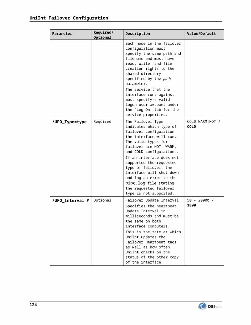
“Points Stale 10(min)” (.Points_Stale_10min) The .Points_Stale_10min Performance Counters Point indicates the number of good points that have not received a new value in the last 10 min. If a point is Good, then it will remain in the good list until the Stale timeout elapses. At this time if the point has not received a new value within the Stale Period then the point will move from the Good count to the Stale count. Only points that are Good can become Stale. If the point is in the In Error count then it will remain in the In Error count until the error clears. As stated above, the total count of Points Good, Points In Error and Points Stale will match the Point Count for the Interface.
“Points Stale 30(min)” (.Points_Stale_30min)The .Points_Stale_30min Performance Counters Point indicates the number of points that have not received a new value in the last 30 min. For a point to be in the Stale 30 minute count it must also be a part of the Stale 10 minute count.
“Points Stale 60(min)” (.Points_Stale_60min)The .Points_Stale_30min Performance Counters Point indicates the number of points that have not received a new value in the last 60 min. For a point to be in the Stale 60 minute count it must also be a part of the Stale 10 minute and 30 minute count.
“Points Stale 240(min)” (.Points_Stale_240min)The .Points_Stale_240min Performance Counters Point indicates the number of points that have not received a new value in the last 240 min. For a point to be in the Stale 240 minute count it must also be a part of the Stale 10 minute, 30 minute and 60 minute count.
Performance Counters for (Scan Class x) only
“Device Scan Time (milliseconds)” (.Device_Scan_Time)A .Device_Scan_Time Performance Counter Point is available for each Scan Class of this Interface.
The .Device_Scan_Time Performance Counters Point indicates the number of milliseconds the Interface takes to read the data from the foreign device and package the data to send to PI. This counter does not include the amount of time to send the data to PI. This point is similar to the [UI_SCINDEVSCANTIME] Health Point.
The ICU uses a naming convention such that the tag containing “(Scan Class 1)” (for example, “sy.perf.etamp390.E1 (Scan Class 1).device_scan _time” refers to Scan Class 1, “(Scan Class 2) refers to Scan Class 2, and so on.
Modbus Ethernet Interface 137

Interface Diagnostics Configuration
“Scan Time (milliseconds)” (.scan_time)A .scan_time Performance Counter Point is available for each Scan Class of this Interface.
The .scan_time Performance Counter Point indicates the number of milliseconds the Interface takes to both read the data from the device and send the data to PI. This point is similar to the [UI_SCINSCANTIME] Health Point.
The ICU uses a naming convention such that the tag containing “(Scan Class 1)” (for example, “sy.perf.etamp390.E1(Scan Class 1).scan_time” refers to Scan Class 1, “(Scan Class 2)” refers to Scan Class 2, and so on.
138
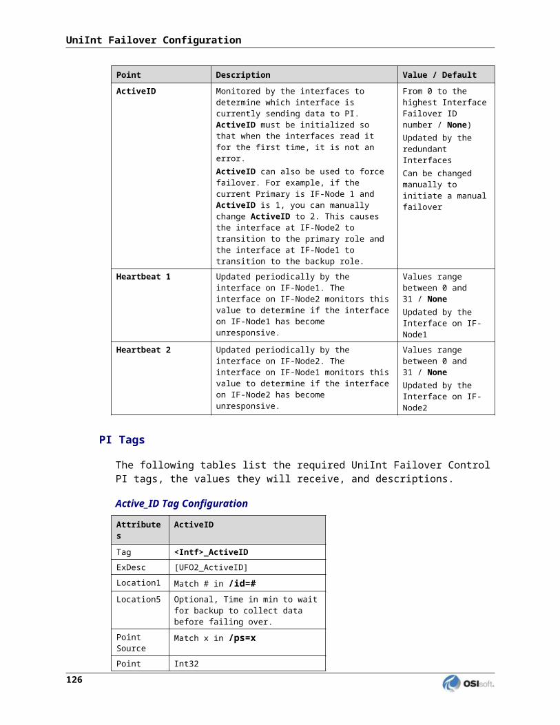
Interface Health Monitoring Points
Interface Health Monitoring Points provide information about the health of this Interface. To use the ICU to configure these points, select this Interface from the Interface drop-down list and click Health Points from the parameter category pane:
Right click the row for a particular Health Point to display the context menu:
Click Create to create the Health Point for that particular row. Click Create All to create all the Health Points.
To see the current values (snapshots) of the Health Points, right click and select Refresh Snapshots.
Modbus Ethernet Interface 139

Interface Diagnostics Configuration
For some of the Health Points described subsequently, the Interface updates their values at each performance summary interval (typically, 8 hours).
[UI_HEARTBEAT]The [UI_HEARTBEAT] Health Point indicates whether the Interface is currently running. The value of this point is an integer that increments continuously from 1 to 15. After reaching 15, the value resets to 1.
The fastest scan class frequency determines the frequency at which the Interface updates this point:
Fastest Scan Frequency Update frequencyLess than 1 second 1 second
Between 1 and 60 seconds, inclusive
Scan frequency
More than 60 seconds 60 seconds
If the value of the [UI_HEARTBEAT] Health Point is not changing, then this Interface is in an unresponsive state.
[UI_DEVSTAT]The interface supports UniInt device status tags. The device status Health tag has the string “[UI_DEVSTAT]” in the extended descriptor (Exdesc) Point Attribute. Please refer to the UniInt Interface User Manual.doc file for more information on how to configure health points. Alternatively, Health tags can be configured with the PI Interface Configuration Utility.
Device status tags can be configured to monitor the status of the devices to which the interface connects. Strings of the following form can be written to the device status tag. Note that the “# |” at the beginning of each error string is for internal use for an application that parses this string.
“Good” - This value indicates that the Interface is able to connect to all of the devices referenced in the Interface’s point configuration. A value of “Good” does not mean that all tags are receiving good values, but it is a good indication that there are no hardware or network problems.
“1 | Starting” – The interface will remain in this status until it has successfully collected data from its first scan. Interfaces that collect data infrequently may stay in this status for a long time.
“Zero devices are currently communicating with the interface.” - This value indicates that the Interface cannot communicate with any of the devices.
“# device(s) failed all of their retries while requesting data.” - This value indicates that the Interface cannot communicate with some of the devices. The number of devices that failed their retries will be recorded and logged.
“4 | Intf Shutdown” - The Interface has shut down.
The Interface updates this point whenever the connection status between the Interface and the PLC(s) or PLC gateway changes.
140

[UI_SCINFO]The [UI_SCINFO] Health Point provides scan class information. The value of this point is a string that indicates
the number of scan classes;
the update frequency of the [UI_HEARTBEAT] Health Point; and
the scan class frequencies
An example value for the [UI_SCINFO] Health Point is:3 | 5 | 5 | 60 | 120
The Interface updates the value of this point at startup and at each performance summary interval.
[UI_IORATE]The [UI_IORATE] Health Point indicates the sum of
1. the number of scan-based input values the Interface collects before it performs exception reporting; and
2. the number of event-based input values the Interface collects before it performs exception reporting; and
3. the number of values that the Interface writes to output tags that have a SourceTag.
The Interface updates this point at the same frequency as the [UI_HEARTBEAT] point. The value of this [UI_IORATE] Health Point may be zero. A stale timestamp for this point indicates that this Interface has stopped collecting data.
[UI_MSGCOUNT]The [UI_MSGCOUNT] Health Point tracks the number of messages that the Interface has written to the pipc.log file since start-up. In general, a large number for this point indicates that the Interface is encountering problems. You should investigate the cause of these problems by looking in pipc.log.
The Interface updates the value of this point every 60 seconds. While the Interface is running, the value of this point never decreases.
[UI_POINTCOUNT]The [UI_POINTCOUNT] Health Point counts number of PI tags loaded by the interface. This count includes all input, output and triggered input tags. This count does NOT include any Interface Health tags or performance points.
The interface updates the value of this point at startup, on change and at shutdown.
Modbus Ethernet Interface 141

Interface Diagnostics Configuration
[UI_OUTPUTRATE]After performing an output to the device, this Interface writes the output value to the output tag if the tag has a SourceTag. The [UI_OUTPUTRATE] Health Point tracks the number of these values. If there are no output tags for this Interface, it writes the System Digital State No Result to this Health Point.
The Interface updates this point at the same frequency as the [UI_HEARTBEAT] point’s. The Interface resets the value of this point to zero at each performance summary interval.
[UI_OUTPUTBVRATE]The [UI_OUTPUTBVRATE] Health Point tracks the number of System Digital State values that the Interface writes to output tags that have a SourceTag. If there are no output tags for this Interface, it writes the System Digital State No Result to this Health Point.
The Interface updates this point at the same frequency as the [UI_HEARTBEAT] point’s. The Interface resets the value of this point to zero at each performance summary interval.
[UI_TRIGGERRATE]The [UI_TRIGGERRATE] Health Point tracks the number of values that the Interface writes to event-based input tags. If there are no event-based input tags for this Interface, it writes the System Digital State No Result to this Health Point.
The Interface updates this point at the same frequency as the [UI_HEARTBEAT] point’s. The Interface resets the value of this point to zero at each performance summary interval.
[UI_TRIGGERBVRATE]The [UI_TRIGGERRATE] Health Point tracks the number of System Digital State values that the Interface writes to event-based input tags. If there are no event-based input tags for this Interface, it writes the System Digital State No Result to this Health Point.
The Interface updates this point at the same frequency as the [UI_HEARTBEAT] point’s. The Interface resets the value of this point to zero at each performance summary interval.
[UI_SCIORATE]You can create a [UI_SCIORATE] Health Point for each Scan Class in this Interface. The ICU uses a tag naming convention such that the suffix “.sc1” (for example, sy.st.etamp390.E1.Scan Class IO Rate.sc1) refers to Scan Class 1, “.sc2” refers to Scan Class 2, and so on.
A particular Scan Class’s [UI_SCIORATE] point indicates the number of values that the Interface has collected. If the current value of this point is between zero and the corresponding [UI_SCPOINTCOUNT] point, inclusive, then the Interface executed the scan successfully. If a [UI_SCIORATE] point stops updating, then this condition indicates that an error has occurred and the tags for the scan class are no longer receiving new data.
The Interface updates the value of a [UI_SCIORATE] point after the completion of the associated scan.
Although the ICU allows you to create the point with the suffix “.sc0”, this point is not applicable to this Interface.
142
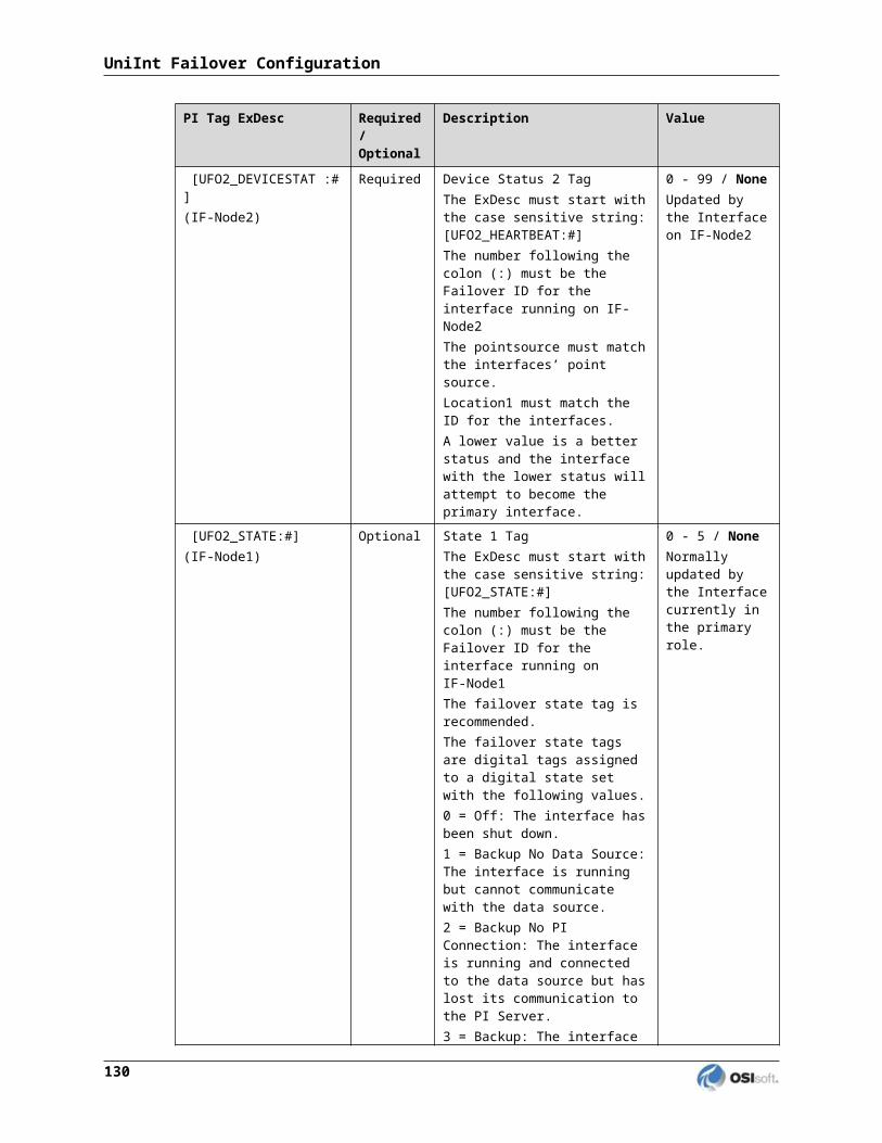
[UI_SCBVRATE]You can create a [UI_SCBVRATE] Health Point for each Scan Class in this Interface. The ICU uses a tag naming convention such that the suffix “.sc1” (for example, sy.st.etamp390.E1.Scan Class Bad Value Rate.sc1) refers to Scan Class 1, “.sc2” refers to Scan Class 2, and so on.
A particular Scan Class’s [UI_SCBVRATE] point indicates the number System Digital State values that the Interface has collected.
The Interface updates the value of a [UI_SCBVRATE] point after the completion of the associated scan.
Although the ICU allows you to create the point with the suffix “.sc0”, this point is not applicable to this Interface.
[UI_SCSCANCOUNT]You can create a [UI_SCSCANCOUNT] Health Point for each Scan Class in this Interface. The ICU uses a tag naming convention such that the suffix “.sc1” (for example, sy.st.etamp390.E1.Scan Class Scan Count.sc1) refers to Scan Class 1, “.sc2” refers to Scan Class 2, and so on.
A particular Scan Class’s [UI_ SCSCANCOUNT] point tracks the number of scans that the Interface has performed.
The Interface updates the value of this point at the completion of the associated scan. The Interface resets the value to zero at each performance summary interval.
Although there is no “Scan Class 0”, the ICU allows you to create the point with the suffix “.sc0”. This point indicates the total number of scans the Interface has performed for all of its Scan Classes.
[UI_SCSKIPPED]You can create a [UI_SCSKIPPED] Health Point for each Scan Class in this Interface. The ICU uses a tag naming convention such that the suffix “.sc1” (for example, sy.st.etamp390.E1.Scan Class Scans Skipped.sc1) refers to Scan Class 1, “.sc2” refers to Scan Class 2, and so on.
A particular Scan Class’s [UI_SCSKIPPED] point tracks the number of scans that the Interface was not able to perform before the scan time elapsed and before the Interface performed the next scheduled scan.
The Interface updates the value of this point each time it skips a scan. The value represents the total number of skipped scans since the previous performance summary interval. The Interface resets the value of this point to zero at each performance summary interval.
Although there is no “Scan Class 0”, the ICU allows you to create the point with the suffix “.sc0”. This point monitors the total skipped scans for all of the Interface’s Scan Classes.
Modbus Ethernet Interface 143

Interface Diagnostics Configuration
[UI_SCPOINTCOUNT]You can create a [UI_SCPOINTCOUNT] Health Point for each Scan Class in this Interface. The ICU uses a tag naming convention such that the suffix “.sc1” (for example, sy.st.etamp390.E1.Scan Class Point Count.sc1) refers to Scan Class 1, “.sc2” refers to Scan Class 2, and so on.
This Health Point monitors the number of tags in a Scan Class.
The Interface updates a [UI_SCPOINTCOUNT] Health Point when it performs the associated scan.
Although the ICU allows you to create the point with the suffix “.sc0”, this point is not applicable to this Interface.
[UI_SCINSCANTIME]You can create a [UI_SCINSCANTIME] Health Point for each Scan Class in this Interface. The ICU uses a tag naming convention such that the suffix “.sc1” (for example, sy.st.etamp390.E1.Scan Class Scan Time.sc1) refers to Scan Class 1, “.sc2” refers to Scan Class 2, and so on.
A particular Scan Class’s [UI_ SCINSCANTIME] point represents the amount of time (in milliseconds) the Interface takes to read data from the device, fill in the values for the tags, and send the values to the PI Server.
The Interface updates the value of this point at the completion of the associated scan.
[UI_SCINDEVSCANTIME]You can create a [UI_SCINDEVSCANTIME] Health Point for each Scan Class in this Interface. The ICU uses a tag naming convention such that the suffix “.sc1” (for example, sy.st.etamp390.E1.Scan Class Device Scan Time.sc1) refers to Scan Class 1, “.sc2” refers to Scan Class 2, and so on.
A particular Scan Class’s [UI_ SCINDEVSCANTIME] point represents the amount of time (in milliseconds) the Interface takes to read data from the device and fill in the values for the tags.
The value of a [UI_ SCINDEVSCANTIME] point is a fraction of the corresponding [UI_SCINSCANTIME] point value. You can use these numbers to determine the percentage of time the Interface spends communicating with the device compared with the percentage of time communicating with the PI Server.
If the [UI_SCSKIPPED] value is increasing, the [UI_SCINDEVSCANTIME] points along with the [UI_SCINSCANTIME] points can help identify where the delay is occurring: whether the reason is communication with the device, communication with the PI Server, or elsewhere.
The Interface updates the value of this point at the completion of the associated scan.
I/O Rate Point
An I/O Rate point measures the rate at which the Interface writes data to its input tags. The value of an I/O Rate point represents a 10-minute average of the total number of values per minute that the Interface sends to the PI Server.
144

When the Interface starts, it writes 0 to the I/O Rate point. After running for ten minutes, the Interface writes the I/O Rate value. The Interface continues to write a value every 10 minutes. When the Interface stops, it writes 0.
The ICU allows you to create one I/O Rate point for each copy of this Interface. Select this Interface from the Interface drop-down list, click IO Rate in the parameter category pane, and check Enable IORates for this Interface.
As the preceding picture shows, the ICU suggests an Event Counter number and a Tagname for the I/O Rate Point. Click the Save button to save the settings and create the I/O Rate point. Click the Apply button to apply the changes to this copy of the Interface.
You need to restart the Interface in order for it to write a value to the newly created I/O Rate point. Restart the Interface by clicking the Restart button:
(The reason you need to restart the Interface is that the PointSource attribute of an I/O Rate point is Lab.)
To confirm that the Interface recognizes the I/O Rate Point, look in the pipc.log for a message such as:PI-ModBus 1> IORATE: tag sy.io.etamp390.ModbusE1 configured.
To see the I/O Rate point’s current value (snapshot), click the Refresh snapshot button:
Modbus Ethernet Interface 145
Interface Diagnostics Configuration
Enable IORates for this InterfaceThe Enable IORates for this interface check box enables or disables I/O Rates for the current interface. To disable I/O Rates for the selected interface, uncheck this box. To enable I/O Rates for the selected interface, check this box.
Event CounterThe Event Counter correlates a tag specified in the iorates.dat file with this copy of the interface. The command-line equivalent is /ec=x, where x is the same number that is assigned to a tag name in the iorates.dat file.
TagnameThe tag name listed under the Tagname column is the name of the I/O Rate tag.
Tag StatusThe Tag Status column indicates whether the I/O Rate tag exists in PI. The possible states are:
Created - This status indicates that the tag exist in PI
Not Created - This status indicates that the tag does not yet exist in PI
Deleted - This status indicates that the tag has just been deleted
Unknown - This status indicates that the PI ICU is not able to access the PI Server
In FileThe In File column indicates whether the I/O Rate tag listed in the tag name and the event counter is in the IORates.dat file. The possible states are:
Yes - This status indicates that the tag name and event counter are in the IORates.dat file
No - This status indicates that the tag name and event counter are not in the IORates.dat file
SnapshotThe Snapshot column holds the snapshot value of the I/O Rate tag, if the I/O Rate tag exists in PI. The Snapshot column is updated when the IORates/Status Tags tab is clicked, and when the Interface is first loaded.
146

Right Mouse Button Menu Options
CreateCreate the suggested I/O Rate tag with the tag name indicated in the Tagname column.
DeleteDelete the I/O Rate tag listed in the Tagname column.
RenameAllow the user to specify a new name for the I/O Rate tag listed in the Tagname column.
Add to FileAdd the tag to the IORates.dat file with the event counter listed in the Event Counter Column.
SearchAllow the user to search the PI Server for a previously defined I/O Rate tag.
Interface Status Point
The PI Interface Status Utility (ISU) alerts you when an interface is not currently writing data to the PI Server. This situation commonly occurs if
the monitored interface is running on an Interface Node, but the Interface Node cannot communicate with the PI Server; or
the monitored interface is not running, but it failed to write at shutdown a System state such as Intf Shut.
The ISU works by periodically looking at the timestamp of a Watchdog Tag. The Watchdog Tag is a tag whose value a monitored interface (such as this Interface) frequently updates. The Watchdog Tag has its excdev, excmin, and excmax point attributes set to 0. So, a non-changing timestamp for the Watchdog Tag indicates that the monitored interface is not writing data.
Please see the Interface Status Interface for complete information on using the ISU. PI Interface Status runs only on a PI Server Node.
If you have used the ICU to configure the PI Interface Status Utility on the PI Server Node, the ICU allows you to create the appropriate ISU point. Select this Interface from the Interface drop-down list and click Interface Status in the parameter category pane. Right click on the ISU tag definition window to bring up the context menu:
Modbus Ethernet Interface 147

Interface Diagnostics Configuration
Click Create to create the ISU tag.
Use the Tag Search button to select a Watchdog Tag. (Recall that the Watchdog Tag is one of the points for which this Interface collects data.)
Select a Scan frequency from the drop-down list box. This Scan frequency is the interval at which the ISU monitors the Watchdog Tag. For optimal performance, choose a Scan frequency that is less frequent than the majority of the scan rates for this Interface’s points. For example, if this Interface scans most of its points every 30 seconds, choose a Scan frequency of 60 seconds. If this Interface scans most of its points every second, choose a Scan frequency of 10 seconds.
If the Tag Status indicates that the ISU tag is Incorrect, right click to enable the context menu and select Correct.
Note: The PI Interface Status Utility - and not this Interface - is responsible for updating the ISU tag. So, make sure that the PI Interface Status Utility is running correctly.
148
Appendix A.Error and Informational Messages
A string NameID is pre-pended to error messages written to the message log. Name is a non-configurable identifier that is no longer than 9 characters. ID is a configurable identifier that is no longer than 9 characters and is specified using the /id parameter on the startup command-line.
Message Logs
The location of the message log depends upon the platform on which the Interface is running. See the UniInt Interface User Manual for more information.
Messages are written to PIHOME\dat\pipc.log at the following times.
When the Interface starts many informational messages are written to the log. These include the version of the interface, the version of UniInt, the command-line parameters used, and the number of points.
As the Interface loads points, messages are sent to the log if there are any problems with the configuration of the points.
If the UniInt /dbUniInt parameter is found in the command-line, then various informational messages are written to the log file.
ModbusE Messages
Informational
Message ID 43480
Message Suspending log messages for 20 seconds...
Meaning Log messages are being suspended for 20 seconds. This message will occur anytime that reduced logging goes into effect. Although the number of seconds in the message here is 20, the actual number will be the number of seconds specified by the /LSI parameter that is described in the Reduced Logging section of the Interface Configuration File chapter.
Message ID 43481
Message Zero devices are currently communicating with the interface.
Meaning None of the configured devices are arecommunicating with the interface. This message will occur after at least one device changes its status from a previous state and now none of the known devices are communicating.
Modbus Ethernet Interface 149

Message ID 43482
Message All devices are now communicating properly.
Meaning All connected devices are now communicating properly. This message will occur after at least one device changes its status from a previous state and now all known devices are communicating.
Message ID 43484
Message Changes to the configuration file have been made.
Meaning Changes to the configuration file have been made without any errors while the interface is running.
Warning
Message ID 43417
Message Tag 'V1' was rejected because it was invalid.
Example Tag 'DemoTag25' was rejected because it was invalid.
Cause The tag was not properly configured.
Resolution The interface will continue on without loading the tag. The tag must be correctly configured and the interface must be restarted before the tag can be loaded.
Meaning The format of this message is the same for all interface parameter out of range errors. The meaning of the values in the message itself are as follows:V1 Long name of the tag
NOTE: This message is preceded by a more specific message noting the exact problem with the tag.
Message ID 43430
Message Load PI point failed for tag 'tagname'. An invalid combination of data type and function code was used in Location3.Values read: Location3 = L3, Data Type = DT, Function Code = FC.
Cause The Location3 attribute of tag tagname contains an invalid combination of data type and function code.
Resolution Modify the Location3 attribute value L3 of tag tagname so that the combination of the function code value FC and the data type value DT is valid.
Modbus Ethernet Interface 150

Message ID 43431
Message Changing function code for tag 'tagname' from 6 to 16. Function code 6 does not support data types 5, 6, 7, 8, 12, 13, 15 and 16.Values read: Location3 = L3, Data Type = DT, Function Code = FC.
Cause The Location3 attribute of tag tagname contains a data type that is not supported by function code 6.
Resolution The interface will change the Location3 attribute value L3 of tag tagname so that the function code value FC is 16.
Message ID 43433
Message PI point 'tagname' has a PI point type that is incompatible with the Modbus data type. Loss of precision or invalid values may occur.
Cause The Location3 attribute of tag tagname contains a data type that is incompatible with the PI point type.
Resolution No resolution is required but the user must be aware of a potential loss of precision or invalid values.
Message ID 43435
Message Optional parameter V1 must be an integer from V2 to V3. It is being set to V4.
Example Optional parameter /DTFMAX must be an integer from 1 to 100. It is being set to 10.
Cause An optional interface or Ethernet node configuration parameter is out of range.
Resolution The interface will set the parameter to the default value.
Meaning The format of this message is the same for all optional interface parameter out of range errors. The meaning of the values in the message itself are as follows:V1 Parameter token (i.e. name)
V2 Minimum possible value for the parameterV3 Maximum possible value for the parameter
V4 Default value for the parameter
Message ID 43439
Message Load PI point failed for tag 'tagname'. Extended descriptor trigger 'EVENT=triggertag' resulted in system error err when attempting to retrieve the trigger tag.
Cause The ExDesc attribute of tag tagname contains a trigger descriptor in which trigger tag triggertag cannot be retrieved. The following are the possible reasons for a failure:
err = -2 The trigger tag name is all spaceserr = -5 Trigger tag not found, or not yet connected to a server
err = >0 A system error occurred
Resolution If err is a negative number the resolution is implied by the error itself. Otherwise, run pidiag –e err to determine why the trigger tag could not be retrieved.
Modbus Ethernet Interface 151

Error and Informational Messages
Message ID 43440
Message Load PI point failed for tag 'tagname'. Extended descriptor trigger 'EVENT' or 'TRIG' can only be used with an input tag.
Cause The ExDesc attribute of output tag tagname contains a trigger descriptor. Only input tags can have a trigger tag.
Resolution Remove the ExDesc attribute trigger descriptor.
Message ID 43441
Message Load PI point failed for tag 'tagname'. Extended descriptor trigger 'EVENT=triggertag' is not valid.
Cause The ExDesc attribute of output tag tagname contains a trigger descriptor which is not valid. The value is probably incorrectly formatted due to extraneous space characters or missing single quote delimiter characters.
Resolution Modify the ExDesc attribute trigger descriptor value triggertag of tag tagname so that it is valid as described in Trigger-based Inputs.
Message ID 43442
Message Load PI point failed for tag 'tagname'. Extended descriptor trigger 'EVENT=triggertag condition' does not contain a valid condition.
Cause The ExDesc attribute of tag tagname contains a trigger descriptor which does not have a valid event condition.
Resolution Modify the ExDesc attribute trigger descriptor event condition value condition of tag tagname so that it is one of the valid event conditions described in Trigger-based Inputs.
Message ID 43443
Message Load PI point failed for tag 'tagname'. Extended descriptor custom data type manipulator 'C=cdtm' is invalid. It must be a value between 0 and 4.
Cause The ExDesc attribute of output tag tagname contains an invalid custom data type manipulator descriptor cdtm. It can only be one of the values described in the Custom Data Type Manipulator section of the ExDesc description.
Resolution Update the ExDesc attribute custom data type manipulator descriptor to be a valid value.
Message ID 43455
Message Required parameter /ID in configuration file is param, but it should match the interface ID of intf.
Cause The interface ID parameter value param in the interface configuration file does not match the interface ID value intf of the interface reading the configuration file.
Resolution This message is only a warning that the interface configuration file may be the wrong one for the interface loading it. At some point the use should ensure that the interface ID of the interface itself and the ID in the configuration file match.
152

Message ID 43473
Message Timeout on node. Retries failed while trying to request data from Node ID plc.
Cause The connection to the device plc on communications node node timed-out.
Resolution This message is a warning that the interface has received no response to requests to the specified device on the specified communications node. This indicates that the device may be temporarily down, communications may be abnormally slow or the retry count needs to be increased.
Message ID 43474
Message Timeout cleared on node Node ID plc.
Cause The connection to the device plc on communications node node resumed after a timeout.
Resolution This message is a warning that the interface has begun receiving a response to requests to the specified device on the specified communications node after it had previously timed-out.
Message ID 43498
Message Required parameter /DN=X is a duplicate node.
Cause The device name parameter value in the configuration file is valid but the node has already been configured.
Resolution Remove the entry from the configuration file or change node to an Ethernet node that has not been configured.
Message ID 43510
Message Tag 'V1' loaded but not ready.Instrument tag 'V2' is not yet a configured node.
Example Tag 'DemoTag25' loaded but not ready.Instrument tag 'plc2.osisoft.int' is not yet a configured node.
Cause The tag was loaded but will not be updated because the Ethernet node of the tag has not been configured yet.
Resolution Once the node has been configured the tag will begin to update.
Meaning The format of this message is the same for all interface parameter out of range errors. The meaning of the values in the message itself are as follows:V1 Long name of the tag
V2 Ethernet node in the instrument tag attribute
Modbus Ethernet Interface 153

Error and Informational Messages
Error
Message ID 43400 to 43411
Message Modbus exception V1 (V2) occurred on a request to PLC V3 on V4.Request values: Function Code = V5, Starting Address = V6, Size = V7
Example Modbus exception 2 (ILLEGAL DATA ADDRESS) occurred on a request to PLC 3 on NODE12.Request values: Function Code = 3, Starting Address = 40000, Size = 12
Cause A request was made that generated a Modbus exception for a response.
Resolution Determine the cause of the exception based on the description found in Appendix E. Modbus Exception Responses. In general, exceptions occur due to one of three issues: incorrectly configured tags, hardware configuration, or the Modbus device is under heavy load.
Meaning The format of this message is the same for all Modbus exceptions. The details of the cause can be found in Appendix E, but the meaning of the values in the message itself are as follows:V1 Exception code
V2 Short description of exceptionV3 Number of PLC node request sent to
V4 Ethernet node request sent toV5 Function code in the request
V6 Starting address in the requestV7 Number of coils/inputs/outputs/registers in the request
154

Message ID 43413
Message The response packet CRC 'V1' did not match the calculated CRC 'V2' of a response from PLC V3 on V4.Request values: Function Code = V5, Starting Address = V6, Size = V7
Example The response packet CRC '52485' did not match the calculated CRC '34273' of a response from PLC 2 on NODE13.Request values: Function Code = 4, Starting Address = 1001, Size = 15
Cause A response packet was received that contained a CRC value that did not match the CRC value calculated by the interface.
Resolution The resolution to this problem will be site or even device specific. Some of the reasons which can cause this exception are an invalid Location2 attribute (sending requests to an unknown PLC), poll delays causing packets to merge, noise on the serial communication line and other unknown factors external to the interface.
Meaning This is a non-standard exception specific to this interface in order to handle the case of an invalid CRC value in the response packet. The meaning of the values in the message are as follows:V1 CRC value contained in the response packetV2 CRC value calculated by the interface
V3 Number of PLC node request sent toV4 Ethernet node request sent to
V5 Function code in the requestV6 Starting address in the request
V7 Number of coils/inputs/outputs/registers in the request
Message ID 43416
Message Required parameter /DN was not found.
Cause The configuration file has a record in which a device name parameter is expected to be the first entry but cannot be found.
Resolution Reconfigure the interface with the Modbus Interface Configurator.
Meaning The configuration file has a record in which the device name parameter is expected as the first parameter but it was not found. This condition is likely to be caused by a configuration file with no COM ports configured or a corrupt configuration file.
Message ID 43418
Message Tag 'tagname' rejected. Instrument tag cannot be blank.
Cause The InstrumentTag attribute is not defined.
Resolution Set the InstrumentTag attribute of tag tagname to COM# in which # is an integer value from 1 to 9999.
Modbus Ethernet Interface 155

Error and Informational Messages
Message ID 43419
Message Tag 'tagname' rejected. System error 'err' occurred when getting the square root attribute.
Cause The SquareRoot attribute of tag tagname could not be retrieved. This problem will normally never occur, but may be due to loss of communications with the PI Server.
Resolution Run pidiag –e err to determine why the attribute could not be retrieved.
Message ID 43420
Message Tag 'tagname' rejected. System error 'err' occurred when getting the conversion factor attribute.
Cause The Convers attribute of tag tagname could not be retrieved. This problem will normally never occur, but may be due to loss of communications with the PI Server.
Resolution Run pidiag –e err to determine why the attribute could not be retrieved.
Message ID 43421
Message Tag 'tagname' rejected. System error 'err' occurred when getting the scan bit attribute.
Cause The scan bit attribute of tag tagname could not be retrieved. This problem will normally never occur, but may be due to loss of communications with the PI Server.
Resolution Run pidiag –e err to determine why the attribute could not be retrieved.
Message ID 43424
Message Load PI point failed for tag 'tagname'. An invalid unit ID of L2 was entered in Location2.The unit ID must be a value between min and max.
Cause The Location2 attribute of tag tagname is out of range.
Resolution Modify the Location2 attribute value L2 of tag tagname so that the Unit ID is between min and max inclusively.
Message ID 43426
Message Load PI point failed for tag 'tagname'. An invalid scan class of L4 was entered in Location4.The scan class must be a value between min and max.
Cause The Location4 attribute of tag tagname is out of range.
Resolution Modify the Location4 attribute value L4 of tag tagname so that the scan class is between min and max inclusively.
156

Message ID 43427
Message Load PI point failed for tag 'tagname'. An invalid register/coil address of L5 was entered in Location5.The address must be a value between min and max.
Cause The Location5 attribute of tag tagname is out of range.
Resolution Modify the Location5 attribute value L5 of tag tagname so that the register/coil address is between min and max inclusively.
Message ID 43428
Message Load PI point failed for tag 'tagname'. An unknown data type was used in Location3.Values read: Location3 = L3, Data Type = DT, Function Code = FC.
Cause The Location3 attribute of tag tagname contains an invalid data type.
Resolution Modify the Location3 attribute value L3 of tag tagname so that the data type value DT is valid.
Message ID 43429
Message Load PI point failed for tag 'tagname'. An unknown function code was used in Location3.Values read: Location3 = L3, Data Type = DT, Function Code = FC.
Cause The Location3 attribute of tag tagname contains an invalid function code.
Resolution Modify the Location3 attribute value L3 of tag tagname so that the function code value FC is valid.
Message ID 43432
Message Load PI point failed for tag 'tagname'. Data type DT can only be used with function codes list.Values read: Location3 = L3, Data Type = DT, Function Code = FC.
Cause The Location3 attribute of tag tagname contains a data type combined with a function code that does not support the data type.
Resolution Modify the Location3 attribute value L3 of tag tagname so that the data type value DT is combined with one of the functions codes in list.
Message ID 43436
Message Load PI point failed for tag 'tagname'. Extended descriptor bitmask option is valid only for data types 1, 7, 9 or 11 with an input tag.
Cause The ExDesc attribute of tag tagname contains a bitmask descriptor which is not supported by the data type of the tag.
Resolution Remove the ExDesc attribute bitmask descriptor of tag tagname or ensure that the tag is an input tag with a supported data type.
Modbus Ethernet Interface 157

Error and Informational Messages
Message ID 43437
Message Load PI point failed for tag 'tagname'. Extended descriptor 'B=bitmask' must be in the form B=uuvvwwxxyyzz where uu, vv, ww, xx, yy and zz each refer to a single bit.
Cause The ExDesc attribute of tag tagname contains a bitmask descriptor which is not valid.
Resolution Modify the ExDesc attribute bit mask descriptor value bitmask of tag tagname so that it is valid as described in Bit Mask.
Message ID 43438
Message Load PI point failed for tag 'tagname'. Extended descriptor 'B=bitmask' must be in the form B=uuvvwwxxyyzz where uu, vv, ww, xx, yy and zz each refer to a single bit and none can be 00.
Cause The ExDesc attribute of tag tagname contains a bitmask descriptor which is not valid, probably because one or more of the masks are 00.
Resolution Modify the ExDesc attribute bit mask descriptor value bitmask of tag tagname so that it is valid as described in Bit Mask.
Message ID 43444
Message Load PI point failed for tag 'tagname'. Extended descriptor custom data type manipulator 'C=cdtm' can only be used with an input tag.
Cause The ExDesc attribute of output tag tagname contains a custom data type manipulator descriptor. Only input tags can have a custom data type manipulator.
Resolution Remove the ExDesc attribute custom data type manipulator descriptor.
Message ID 43445
Message Load PI point failed for tag 'tagname'. Extended descriptor 'SWAP' is only valid for data types 4, 6, 7, 13, 15, 16 and strings.
Cause The ExDesc attribute of output tag tagname contains a swap descriptor. Only tags with a data type of 4, 6, 7, 13, 15, 16 or string (101 to 199) can have a swap descriptor.
Resolution Remove the ExDesc attribute swap descriptor.
Message ID 43446
Message Required parameter /ID must be an integer from 1 to 2147483647. It was being set to id.
Cause The interface ID command-line parameter value id is not a valid interface ID.
Resolution Reconfigure the interface so that the interface ID is an integer value from 1 to 99. See Configuring the Interface with PI ICU.
158

Message ID 43447
Message Required parameter /ID was not found.
Cause There is no interface ID command-line parameter.
Resolution Reconfigure the interface. See Configuring the Interface with PI ICU.
Message ID 43448
Message The parameter 'param' is not a known parameter.
Cause The command-line parameter param is not a valid parameter.
Resolution Remove the unknown command-line parameter.
Message ID 43449
Message Required parameter /ICF was not found.
Cause There is no interface configuration file command-line parameter.
Resolution Reconfigure the interface. See Configuring the Interface with PI ICU.
Message ID 43450
Message The interface configuration file must have a '.csv' extension.
Cause The interface configuration file name specified by the /ICF command-line parameter does not have a .CSV file extension.
Resolution Rename the interface configuration file or change the file name specified by the /ICF command-line parameter.
Message ID 43451
Message The interface configuration file 'file.csv' could not be opened.
Cause The interface configuration file name file.csv specified by the /ICF command-line parameter could not be opened.
Resolution The likely cause of this error is that the interface configuration file file.csv does not exist.
Message ID 43452
Message An unknown error occurred when reading the communications configuration file.
Cause An error occurred when reading the interface configuration file. This error is caused by records in the file that do not represent the interface or a COM port. A likely cause is extraneous empty records inadvertently added when manually editing the interface configuration file.
Resolution Only edit the interface configuration file with the Modbus Interface Configurator utility.
Modbus Ethernet Interface 159

Error and Informational Messages
Message ID 43453
Message The debug trace file must have a '.txt' extension.
Cause The debug trace file name specified by the /DTF command-line parameter does not have a .TXT file extension.
Resolution Rename the file name specified by the /DTF command-line parameter.
Message ID 43454
Message Optional parameter /DTF must specify a file name.
Cause The debug trace file command-line parameter /DTF must specify a valid file name with a .txt extension.
Resolution Remove the /DTF command-line parameter or set a valid file name as the parameter value.
Message ID 43496
Message Required parameter /DN must be in the form /DN=x:y in which x is a valid IP address or hostname. It was being set to addr.
Cause The device name parameter value in the configuration file is in the correct format but the IP address or hostname addr is not valid.
Resolution Set the /DN parameter value to x:y in which x is a valid IP address or hostname and y is a valid service port number.
Message ID 43497
Message Required parameter /DN must be in the form /DN=x:y in which x is a valid IP address or hostname and y is a port number.
Cause The device name parameter value in the configuration file is not valid. It has an invalid format or the IP address, hostname or service post is invalid.
Resolution Set the /DN parameter value to x:y in which x is a valid IP address or hostname and y is a valid service port number.
Message ID 43499
Message Tag 'tagname' Instrument Tag attribute 'node' is not a valid IP address or hostname.
Cause The InstrumentTag attribute node is not in a valid format. This error will only occur if the node passes interface validation but fails Windows system validation.
Resolution Modify the InstrumentTag attribute node of tag tagname so that it is in a valid IP address or hostname format.
160

Message ID 43500
Message Tag 'tagname' Instrument Tag attribute 'node' is not a valid IP address.It must be in the form of x.x.x.x, where x is a number from 0 to 255 and does not have a leading zero.
Cause The InstrumentTag attribute node is not in a valid format. One or more parts of the IP address contain a leading zero. Since a leading zero will cause the part to interpret as an octal number the interface does not support that format to prevent multiple IP addresses resolving to a single unique node.
Resolution Modify the InstrumentTag attribute node of tag tagname so that it is in a valid IP address format without a leading zero for any part of the address.
Message ID 43501
Message Tag 'tagname' Instrument Tag attribute 'node' is not a valid IP address.It must be in the form of x.x.x.x, where x is a number from 0 to 255.
Cause The InstrumentTag attribute node is not in a valid format. One or more parts of the IP address contain more than 3 digit characters or represent a value of greater than 255.
Resolution Modify the InstrumentTag attribute node of tag tagname so that it is in a valid IP address format with no part of the address being greater than 255 or containing more than 3 digit characters.
Message ID 43502
Message Tag 'tagname' Instrument Tag attribute 'node' is not a valid IP address or hostname.It cannot have contiguous period (.) delimiter characters.
Cause The InstrumentTag attribute node is not in a valid format. The IP address or hostname contains contiguous period delimiter characters.
Resolution Modify the InstrumentTag attribute node of tag tagname so that it is in a valid IP address or hostname format.
Message ID 43503
Message Tag 'tagname' Instrument Tag attribute 'node' is not a valid hostname.Each part of the complete name must be delimited by a period (.) and cannot begin or end with a hyphen (-) or underscore (_) character.
Cause The InstrumentTag attribute node is not in a valid format. One or more parts of the hostname begin or end with a hyphen or underscore character.
Resolution Modify the InstrumentTag attribute node of tag tagname so that it is in a valid hostname format.
Modbus Ethernet Interface 161

Error and Informational Messages
Message ID 43504
Message Tag 'tagname' Instrument Tag attribute 'node' is not a valid hostname.It must begin with an alphabetic (a to z) or numeric (0 to 9) character.
Cause The InstrumentTag attribute node is not in a valid format. The first character in the complete hostname is not alphabetic or numeric.
Resolution Modify the InstrumentTag attribute node of tag tagname so that it is in a valid hostname format.
Message ID 43505
Message Tag 'tagname' Instrument Tag attribute 'node' is not a valid hostname.It must end with an alphabetic (a to z) or numeric (0 to 9) character.
Cause The InstrumentTag attribute node is not in a valid format. The last character in the complete hostname is not alphabetic or numeric.
Resolution Modify the InstrumentTag attribute node of tag tagname so that it is in a valid hostname format.
Message ID 43506
Message Tag 'tagname' Instrument Tag attribute 'node' is not a valid hostname.It must contain only alphabetic (a to z), numeric (0 to 9), hyphen (-), underscore (_) and period (.) characters.
Cause The InstrumentTag attribute node is not in a valid format. It contains one or more characters that are not an alphabetic, numeric, hyphen, underscore or period character.
Resolution Modify the InstrumentTag attribute node of tag tagname so that it is in a valid hostname format.
Message ID 43507
Message Tag 'tagname' Instrument Tag attribute 'node' is not a valid hostname.Each part cannot contain more than 63 characters.
Cause The InstrumentTag attribute node is not in a valid format. One or more parts of the hostname contain more than 63 characters.
Resolution Modify the InstrumentTag attribute node of tag tagname so that it is in a valid hostname format.
162

Message ID 43508
Message Tag 'tagname' Instrument Tag attribute 'node' is not a valid hostname.It cannot contain more than 255 characters.
Cause The InstrumentTag attribute node is not in a valid format. The complete hostname contains more than 255 characters.
Resolution Modify the InstrumentTag attribute node of tag tagname so that it is in a valid hostname format.
Message ID 43509
Message Tag 'tagname' rejected. Instrument tag 'node' is not a configured node.
Cause The InstrumentTag attribute node is valid but has not been configured.
Resolution Modify the InstrumentTag attribute node of tag tagname to a valid, configured node or configure the node represented by node.
System Errors and PI Errors
System errors are associated with positive error numbers. Errors related to PI are associated with negative error numbers.
Error Descriptions on WindowsOn Windows descriptions of system and PI errors can be obtained with the pidiag utility:
Windows: \PI\adm\pidiag - e error_number
Modbus Ethernet Interface 163

Error and Informational Messages
UniInt Failover Specific Error Messages
Informational
Message 16-May-06 10:38:00modbusE 1> UniInt failover: Interface in the “Backup” state.
Meaning Upon system startup, the initial transition is made to this state. While in this state the interface monitors the status of the other interface participating in failover. When configured for Hot failover, data received from the data source is queued and not sent to the PI Server while in this state. The amount of data queued while in this state is determined by the failover update interval. In any case, there will be typically no more than two update intervals of data in the queue at any given time. Some transition chains may cause the queue to hold up to five failover update intervals worth of data.
Message 16-May-06 10:38:05modbusE 1> UniInt failover: Interface in the “Primary” state and actively sending data to PI. Backup interface not available.
Meaning While in this state, the interface is in its primary role and sends data to the PI Server as it is received. This message also states that there is not a backup interface participating in failover.
Message 16-May-06 16:37:21modbusE 1> UniInt failover: Interface in the “Primary” state and actively sending data to PI. Backup interface available.
Meaning While in this state, the interface sends data to the PI Server as it is received. This message also states that the other copy of the interface appears to be ready to take over the role of primary.
164

Errors (Phase 1 & 2)
Message 16-May-06 17:29:06modbusE 1> One of the required Failover Synchronization points was not loaded. Error = 0: The Active ID synchronization point was not loaded.The input PI tag was not loaded
Cause The Active ID tag is not configured properly.
Resolution Check validity of point attributes. For example, make sure Location1 attribute is valid for the interface. All failover tags must have the same PointSource and Location1 attributes. Modify point attributes as necessary and restart the interface.
Message 16-May-06 17:38:06modbusE 1> One of the required Failover Synchronization points was not loaded.Error = 0: The Heartbeat point for this copy of the interface was not loaded.The input PI tag was not loaded
Cause The Heartbeat tag is not configured properly.
Resolution Check validity of point attributes. For example, make sure Location1 attribute is valid for the interface. All failover tags must have the same PointSource and Location1 attributes. Modify point attributes as necessary and restart the interface.
Message 17-May-06 09:06:03modbusE > The Uniint FailOver ID (/UFO_ID) must be a positive integer.
Cause The UFO_ID parameter has not been assigned a positive integer value.
Resolution Change and verify the parameter to a positive integer and restart the interface.
Message 17-May-06 09:06:03modbusE 1> The Failover ID parameter (/UFO_ID) was found but the ID for the redundant copy was not found
Cause The /UFO_OtherID parameter is not defined or has not been assigned a positive integer value.
Resolution Change and verify the /UFO_OtherID parameter to a positive integer and restart the interface.
Modbus Ethernet Interface 165

Error and Informational Messages
Errors (Phase 2)
Unable to open synchronization file
Message 27-Jun-08 17:27:17PI Eight Track 1 1> Error 5: Unable to create file ‘\\georgiaking\GeorgiaKingStorage\UnIntFailover\\PIEightTrack_eight_1.dat’Verify that interface has read/write/create access on file server machine.Intializing uniint library failedStopping Interface
Cause This message will be seen when the interface is unable to create a new failover synchronization file at startup. The creation of the file only takes place the first time either copy of the interface is started and the file does not exist. The error number most commonly seen is error number 5. Error number 5 is an “access denied” error and is likely the result of a permissions problem.
Resolution Ensure the account the interface is running under has read and write permissions for the folder. The “log on as” property of the Windows service may need to be set to an account that has permissions for the folder.
Error Opening Synchronization File
Message Sun Jun 29 17:18:51 2008PI Eight Track 1 2> WARNING> Failover Warning: Error = 64Unable to open Failover Control File ‘\\georgiaking\GeorgiaKingStorage\Eight\PIEightTrack_eight_1.dat’The interface will not be able to change state if PI is not available
Cause This message will be seen when the interface is unable to open the failover synchronization file. The interface failover will continue to operate correctly as long as communication to the PI Server is not interrupted. If communication to PI is interrupted while one or both interfaces cannot access the synchronization file, the interfaces will remain in the state they were in at the time of the second failure, so the primary interface will remain primary and the backup interface will remain backup.
Resolution Ensure the account the interface is running under has read and write permissions for the folder and file. The “log on as” property of the Windows service may need to be set to an account that has permissions for the folder and file.
166

Appendix B.PI SDK Options
To access the PI SDK settings for this Interface, select this Interface from the Interface drop-down list and click UniInt - PI SDK in the parameter category pane.
Disable PI SDKSelect Disable PI SDK to tell the Interface not to use the PI SDK. If you want to run the Interface in Disconnected Startup mode, you must choose this option.
The command line equivalent for this option is /pisdk=0.
Use the Interface’s default settingThis selection has no effect on whether the Interface uses the PI SDK. However, you must not choose this option if you want to run the Interface in Disconnected Startup mode.
Enable PI SDKSelect Enable PI SDK to tell the Interface to use the PI SDK. Choose this option if the PI Server version is earlier than 3.4.370.x or the PI API is earlier than 1.6.0.2, and you want to use extended lengths for the Tag, Descriptor, ExDesc, InstrumentTag, or PointSource point attributes. The maximum lengths for these attributes are:
Attribute Enable the Interface to use the PI SDK
PI Server earlier than 3.4.370.x or PI API earlier than 1.6.0.2, without the use of the PI SDK
Tag 1023 255
Descriptor 1023 26
ExDesc 1023 80
InstrumentTag 1023 32
PointSource 1023 1
However, if you want to run the Interface in Disconnected Startup mode, you must not choose this option.
The command line equivalent for this option is /pisdk=1.
Modbus Ethernet Interface 167

Modbus Ethernet Interface 168

Appendix C.Floating Point Representation
The manner in which PLCs store floating-point numbers vary. As a result, the Modbus commands that are needed to retrieve floating point values will also vary from PLC to PLC. The user can specify the manner in which the PLC stores a floating point with the data type parameter that is discussed under “Point Definition” earlier in this manual.
NOTE: To make matters more complicated for the software developer, different operating systems (e.g. Windows, VAX, UNIX) store IEEE floating point numbers differently. Standard 4-byte IEEE floating points on Intel Windows are represented as follows:
byte 3: S MSBE E E E E E Ebyte 2: LSBE MSBF F F F F F F byte 1: F F F F F F F Fbyte 0: F F F F F F F LSBF
where,
S = sign bit (1 = -)MSBE = most significant bit exponentLSBE = least significant bit exponentMSBF = most significant bit fractionLSBF = least significant bit fraction
For example, the number 1 is stored as a floating-point number by:
byte 0 = 0 byte 1 = 0 byte 2 = 0x80 byte 3 = 0x3f
where 0x80 and 0x3f are hexadecimal numbers.
All floating-point values will be returned in two registers. For purposes of discussion, the “low-order register” will contain bytes 0 and 1, and the “high-order register” will contain bytes 2 and 3. This definition is somewhat arbitrary because the byte order is reversed, for example, on VAX platforms. Hence the “low” and “high” order bytes are swapped. Also, there is no good reason to consider byte 3 (the byte with the exponent) of higher order than byte 1 or byte 0 (bytes containing the fraction).
Some PLC’s will send the low register back first and then the high register, while other PLC’s will send the high register back first and then the low register. The order in which the ModbusE interface expect the bytes is different for each data type (see below).
The interface currently supports 3 different methods of reading and writing IEEE floating point numbers. Data types 4, 5 and 6 (defined in the Location3) are IEEE floating points.
The interface can also read Siemens type floating point values (data type 8), but writes of Siemens floats are not supported. 4-byte integers (data type 7) are also discussed below.
Modbus Ethernet Interface 169

Floating Point, Data Type 4
This type of PLC maps a single register to 2 different registers that contain the floating-point value. For example register 235 could point to the floating-point value contained in registers 625 and 626, and register 236 could point to the floating-point value contained in registers 888 and 889. For the request sent to the PLC, the number of data registers specified will be 1 per floating point. By default the ModbusE interface expects the low order register first followed by the high order register. The Fisher Remote Operational Controller (ROC) Emulation uses this type of floating point.
Floating Point, Data Type 5
This type of PLC stores a floating point in two consecutive registers; for example registers 625 and 626. The interesting thing about this floating point type is that for each request sent to the PLC, the number of data registers specified is 1 per floating point. By default, the ModbusE interface expects the low order register first followed by the high order register. The SOLAR APRIL-5000 PLC uses this type of floating point.
Floating Point, Data Type 6
This type of PLC also stores a floating point in two consecutive registers. However the request to the PLC must specify 2 data registers per floating point. The default is to expect the high order register first followed by the low order register. The GE 9070 and Micro Motion Mass Flow Meters return the bytes in this order. Modicon PLCs return the low order register first followed by the high-order register. Hence, the /swap6 parameter should be specified in the startup command file for Modicon PLCs.
Floating Point, Data Type 7
Floating Point Data Represented as 4-byte Integers.
Certain devices, such as the Motherwell Controls Series 5000 Tank Gauging System, represent floating point numbers in an integer format. These values require division by a conversion factor to convert them from integers to their proper floating-point value. For example, the floating-point value of 16.4 can be represented by a 2 byte integer containing the value of 164: byte0 = 0, byte1 = 164 (decimal). A conversion factor of 10 is used (the raw value is divided by 10) to convert the value to 16.4. A floating-point value of -16.4 can be represented by a 2-byte integer containing -164; byte0 = 255, byte1 = 92. Again the value is divided by the conversion factor, 10, to yield -16.4. The integer range for 2 byte integers is (-32768) to (32767).
Four (4) byte integers can also be used to hold floating point numbers. The same conversion equation that applies to 2 byte integers applies to 4 byte integers as well. Data type 7 is used to indicate that data will be 4-byte integer values. The integer range for 4 byte integers is (-2147483648) to (2147483647).
Modbus Ethernet Interface 170

The Square Root Code should be set to 3 to indicate the integer to floating point conversion as described above. The appropriate Conversion Factor should be entered and the Point Type should be R. For integer representation, only the following Location3 entries are supported at the present time: 103, 104, 703, 704 and (for write) 106, 706. The default is for the ModbusE interface to expect the high order register first.
Siemens Floating-Point Representation, Data Type 8
Siemens Floating points are supported only for inputs.
The Siemens PLC uses a special bitmap representation. The float bitmap representation is listed below:
Bits map: 31 30 29 28 27 26 25 24 23 22 21 20 ....................................01 00Siemens: S X X X X X X X S M M M ...................................M M
where: S=Sign Bits, X=Exponent Bits, and M=Mantissa
Bit31 is the sign bit of the exponent,Bit30 to Bit24 represent a decimal value of ..... (64 ... 1) and are used to compose the exponent,Bit23 is the sign bit of the mantissa,bit22 to Bit00 represent a decimal value of ..... and are used to compose the mantissa.
The following formula is used to generate the decimal value from the four bytes that are sent:
Where Mantissa is formed as follows:
and the Exponent:
The default is for the ModbusE interface to expect the high order register first
Function Code 65
Some PLC’s are able to understand function code 65, which is a non-standard Modbus function code. One type of PLC that understands function code 65 is called an HTMUX box. If such a PLC receives function code 65, it knows that a 4-byte floating point should be returned.
Each register that can be read with function code 65 contains 4 bytes of information. Standard registers can hold only two bytes of information. Function code 65 is similar to data type 4 above, except that there is no need to map a single register to two different registers. Each register can already hold 4 bytes.
Modbus Ethernet Interface 171

Floating Point Representation
Enron Floating Point Type
Enron floating points are the same as the data type 4 floating points mentioned above, with the exception that the /swap4 parameter should be specified on the startup command line.
172

Appendix D.Modbus Message Packets
The message packets that are described below correspond to the Modbus TCP/IP protocol. Although it is not shown in the graphical packet representations below, the standard Modbus TCP/IP packet includes a Modbus Application Protocol (MBAP) header for both request and response packets. The header is as follows:
Transaction Identifier 2 Bytes 0
Protocol Identifier 2 Bytes 0
Length 2 Bytes Number of remaining bytes in packet
Unit ID (PLC Node) 1 Byte 1 to 255
The graphical packet representations for each function code below only contain the PLC Node Address (i.e. Unit Identifier) because the header is the same for all packets and an Ethernet node may be configured not to use the standard MBAP header (see TCP/IP Header). Even in the event that the node is configured so that the header is not used, the PLC Node Address will still be in the message packet. In addition, if the standard MBAP header is configured not to be used, a 2 byte cyclic redundancy check (CRC) value will be appended to the end of each packet and will be validated by the interface.
For more information on Modbus message packets, see the Modbus Protocol Reference Guide, available from AEG Schneider Automation. And additional reference on Modbus message packets is the Modbus Application Protocol Specification V1.1b which can be found on the website http://www.Modbus-IDA.org.
Modbus Ethernet Interface 173

Function Code 1: Read Coils
Request
PLC Node Address 1 Byte 1 to 255
Function Code 1 Byte 0x01
Starting Address 2 Bytes 0x0000 to 0xFFFF
Quantity of Coils 2 Bytes 1 to 2000
Response
PLC Node Address 1 Byte 1 to 255
Function Code 1 Byte 0x01
Byte Count 1 Byte N = Quantity of coils / 8
Coil Status N Bytes Value(s)
Function Code 2: Read Discrete Inputs
Request
PLC Node Address 1 Byte 1 to 255
Function Code 1 Byte 0x02
Starting Address 2 Bytes 0x0000 to 0xFFFF
Quantity of Inputs 2 Bytes 1 to 2000
Response
PLC Node Address 1 Byte 1 to 255
Function Code 1 Byte 0x02
Byte Count 1 Byte N = Quantity of inputs / 8
Input Status N Bytes Value(s)
Modbus Ethernet Interface 174

Function Code 3: Read Holding Registers
Request
PLC Node Address 1 Byte 1 to 255
Function Code 1 Byte 0x03
Starting Address 2 Bytes 0x0000 to 0xFFFF
Quantity of Registers 2 Bytes 1 to 125
Response
PLC Node Address 1 Byte 1 to 255
Function Code 1 Byte 0x03
Byte Count 1 Byte 2 * N (Quantity of registers)
Holding Registers N * 2 Bytes Value(s)
Function Code 4: Read Input Registers
Request
PLC Node Address 1 Byte 1 to 255
Function Code 1 Byte 0x04
Starting Address 2 Bytes 0x0000 to 0xFFFF
Quantity of Registers 2 Bytes 1 to 125
Response
PLC Node Address 1 Byte 1 to 255
Function Code 1 Byte 0x04
Byte Count 1 Byte 2 * N (Quantity of registers)
Holding Registers N * 2 Bytes Value(s)
Modbus Ethernet Interface 175

Modbus Message Packets
Function Code 5: Write Single Coil
Request
PLC Node Address 1 Byte 1 to 255
Function Code 1 Byte 0x05
Output Address 2 Bytes 0x0000 to 0xFFFF
Output Value 2 Bytes 0x0000 or 0xFF00
Response
PLC Node Address 1 Byte 1 to 255
Function Code 1 Byte 0x05
Output Address 2 Bytes 0x0000 to 0xFFFF
Output Value 2 Bytes 0x0000 or 0xFF00
Function Code 6: Write Single Register
Request
PLC Node Address 1 Byte 1 to 255
Function Code 1 Byte 0x06
Register Address 2 Bytes 0x0000 to 0xFFFF
Register Value 2 Bytes 0x0000 to 0xFFFF
Response
PLC Node Address 1 Byte 1 to 255
Function Code 1 Byte 0x06
Register Address 2 Bytes 0x0000 to 0xFFFF
Register Value 2 Bytes 0x0000 to 0xFFFF
176

Function Code 15: Write Multiple Coils
Request
PLC Node Address 1 Byte 1 to 255
Function Code 1 Byte 0x0F
Starting Address 2 Bytes 0x0000 to 0xFFFF
Quantity of Outputs 2 Bytes 1 to 1968
Byte Count 1 Byte N = Quantity of outputs / 8
Outputs Value N Bytes Value(s)
Response
PLC Node Address 1 Byte 1 to 255
Function Code 1 Byte 0x0F
Starting Address 2 Bytes 0x0000 to 0xFFFF
Quantity of Outputs 2 Bytes 1 to 1968
Function Code 16: Write Multiple Registers
Request
PLC Node Address 1 Byte 1 to 255
Function Code 1 Byte 0x10
Starting Address 2 Bytes 0x0000 to 0xFFFF
Quantity of Registers 2 Bytes 1 to 123
Byte Count 1 Byte 2 * N (Quantity of registers)
Outputs Value N * 2 Bytes Value(s)
Response
PLC Node Address 1 Byte 1 to 255
Function Code 1 Byte 0x10
Starting Address 2 Bytes 0x0000 to 0xFFFF
Quantity of Registers 2 Bytes 1 to 123
Modbus Ethernet Interface 177

Appendix E. Modbus Exception Responses
Modbus exception responses are returned to the interface from the PLC when there is an operational or programming error associated with a command from the interface. The format of a Modbus exception response packet and a list of possible exception response codes are shown below:
Exception Response Packet
If a Modbus device responds to a request with an exception response, a value of 0x80 will be added to the function code with a logical OR operation to form the error code in the response packet. It will be followed by one of the exception codes that represent the reason for the error in the next byte of the packet. For example, if a read holding request (function code 0x03) fails the response will contain 0x83 for the error code. The format of an exception response packet is shown below:
PLC Node Address 1 Byte 1 to 255
Error Code 1 Byte 0x83
Exception Code 1 Byte 01 or 02 or 03 or 04
Modbus Ethernet Interface 179
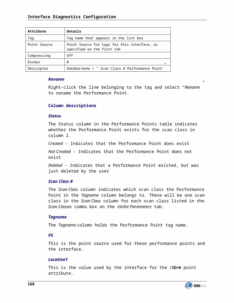
Exception Codes
When an exception occurs the interface will write the exception code and a short description of the exception to the PI log. A list of possible exception response codes is shown below along with the corresponding PI log message text and the meaning of the exception:
Code (Hex)
Message ID
Log Message Text Meaning
01 43400 ILLEGAL FUNCTION The function code received in the query is not an allowable action for the server (or slave). This may be because the function code is only applicable to newer devices, and was not implemented in the unit selected. It could also indicate that the server (or slave) is in the wrong state to process a request of this type, for example because it is not configured and is being asked to return register values.
02 43401 ILLEGAL DATA ADDRESS The data address received in the query is not an allowable address for the server (or slave). More specifically, the combination of reference number and transfer length is invalid. For a controller with 100 registers, the PDU addresses the first register as 0, and the last one as 99. If a request is submitted with a starting register address of 96 and a quantity of registers of 4, then this request will successfully operate (address-wise at least) on registers 96, 97, 98, 99. If a request is submitted with a starting register address of 96 and a quantity of registers of 5, then this request will fail with Exception Code 0x02 “Illegal Data Address” since it attempts to operate on registers 96, 97, 98, 99 and 100, and there is no register with address 100.
03 43402 ILLEGAL DATA VALUE A value contained in the query data field is not an allowable value for server (or slave). This indicates a fault in the structure of the remainder of a complex request, such as that the implied length is incorrect. It specifically does NOT mean that a data item submitted for storage in a register has a value outside the expectation of the application program, since the MODBUS protocol is unaware of the significance of any particular value of any particular register.
04 43403 SLAVE DEVICE FAILURE An unrecoverable error occurred while the server (or slave) was attempting to perform the requested action.
05 43404 ACKNOWLEDGE Specialized use in conjunction with programming commands.The server (or slave) has accepted the request and is processing it, but a long duration of time will be required to do so. This response is returned to prevent a
Modbus Ethernet Interface 180

Code (Hex)
Message ID
Log Message Text Meaning
timeout error from occurring in the client (or master). The client (or master) can next issue a Poll Program Complete message to determine if processing is completed.
06 43405 SLAVE DEVICE BUSY Specialized use in conjunction with programming commands.The server (or slave) is engaged in processing a long–duration program command. The client (or master) should retransmit the message later when the server (or slave) is free.
07 43406 NEGATIVE ACKNOWLEDGEMENT
The slave cannot perform the program function received in the query. This code is returned for an unsuccessful programming request using function code 13 or 14 (codes not supported by this interface). The master should request diagnostic information from the slave.NOTE: This exception code is for function codes not supported by this interface, but is included to be fully compatible with all Modbus exceptions.
08 43407 MEMORY PARITY ERROR Specialized use in conjunction with function codes 20 and 21 and reference type 6, to indicate that the extended file area failed to pass a consistency check.The server (or slave) attempted to read record file, but detected a parity error in the memory. The client (or master) can retry the request, but service may be required on the server (or slave) device.
10 43408 GATEWAY PATH UNAVAILABLE
Specialized use in conjunction with gateways; indicates that the gateway was unable to allocate an internal communication path from the input port to the output port for processing the request. Usually means that the gateway is not configured correctly or overloaded.
11 43409 GATEWAY TARGET DEVICE FAILED TO RESPOND
Specialized use in conjunction with gateways; indicates that no response was obtained from the target device. Usually means that the device is not present on the network.
21 43410 Response CRC did not match calculated CRC
Indicates that the CRC contained in the response packet does not match the CRC calculated by the interface after receiving the packet.NOTE: This exception code is not standard Modbus and is provided by the interface so that a CRC mismatch will be handled as if it is an exception.
?? 43411 Unknown Error Indicates an undefined exception occurred. This should never occur, but will be handled by the interface as if a known exception occurred.
Modbus Ethernet Interface 181

Appendix F. Tag Optimization
The optimization of tags is an essential part of tag configuration. It can make the difference between good performance when collecting tag values and an interface that gets bogged down with a plethora of requests to a number of PLCs with varying degrees of performance. For input tags, tag configuration optimization is relatively easy and only requires a logical grouping of related tags. For output tags, tag configuration optimization is critical and can make a difference on whether or not the tags ever even get updated.
Input Tags
Tag Groups
Due to the functionality of the Modbus application protocol, a single read request may result in a response with data for up to 2,000 tags. The table below lists the maximum number of coils, inputs or registers that may be read with a single request:
Function Code
Description Maximum Quantity
1 Read Coils 2000 coils
2 Read Discrete Inputs 2000 inputs
3 Read Holding Registers 125 registers
4 Read Input Registers 125 registers
To enhance performance by maximizing the use of a single read request, the interface will place tags in groups based on the Ethernet node, PLC node (location 2), function code (location 3), data type (location 3) and scan class (location 4) being equal and the data offset (location 5) being within a range of offsets based on the maximum quantity of values that can be requested. Given that the Modbus application protocol allows for a maximum of 250 bytes of data in a response, the following formula is used to compute the maximum number of register values that may be read in a single request (since coils and discrete inputs are bits, the maximum number is fixed):
Maximum Quantity = 250 / (Registers per data type * 2 bytes per register)
For example, since data type 1 (16-bit integer) is represented in a single register, the maximum quantity of values in input or holding registers that can be read by a single request is 125. On the other hand, since data type 7 (4-byte integer) is represented in two registers, the maximum quantity of values in input or holding registers that can be read by a single request is 62 (in this case the maximum quantity is rounded down so that the total number of bytes does not exceed 250).
Modbus Ethernet Interface 183

The data offset range for a tag group is predetermined by the interface and is computed based on the maximum quantity of values allowed in a single read request and the first valid data offset. For example, given a data type with a value represented by single 2-byte register, a maximum quantity allowed of 125 values and 2,000 available registers, the first tag group would contain offsets 1 to 125, the second tag group offsets would be 126 to 250, and so on. The following table demonstrates the ranges of offsets for tags with function code 3 (read holding registers) and data type 1 (signed 16-bit integer):
Tag Group First Offset Last Offset
1 1 125
2 126 250
3 251 375
4 376 500
.
.
.
.
.
.
16 1876 2000
Optimization
Since the interface will assemble related tags into groups in order to maximize the number of tag values requested in a single Modbus read command, it is best for the user to configure related tags in a manner in which tag groups can be leveraged to minimize the number of requests for the tag data. In other words, the more related tags whose data offsets fit within the range of offsets of a given tag group the better.
For example, assume that a user creates 100 tags with the attribute values specified in the following table:
Point Attribute Description Value
Instrument Tag Ethernet node COM3
Location 2 PLC Node 2
Location 3 Read input register containing 16-bit unsigned integer 1104
Location 4 Scan Class 1
Modbus Ethernet Interface 184

Example 1If the 100 tags have data offsets of 1 to 20, 101 to 120, 201 to 220, 301 to 320 and 401 to 420 respectively, the tags will be represented by four tag groups: tag groups 1, 2, 3 and 4. The following table represents how the tags will be located in the four groups:
Tag Group Tag Offsets
1 1 to 20, 101 to 120
2 201 to 220
3 301 to 320
4 401 to 420
In this case four requests will have to be made to read the values for the 100 tags.
Example 2If the 100 tags have data offsets of 101 to 200, the tags will be represented by two tag groups: tag groups 1 and 2. The following table represents how the tags will be located in the two groups:
Tag Group Tag Offsets
1 101 to 125
2 126 to 200
In this case two requests will have to be made to read the values for the 100 tags.
Example 3If the 100 tags have data offsets of 11 to 110, the tags will be represented by one tag group: tag group 1. In this case a single request will have to be made to read the values for the 100 tags.
While it may not always be possible to configure tags in a manner in which the absolute minimum number to tag groups are required, it is important to try to configure the tags in a way in which as much optimization can be achieved as possible. Since performance is heavily dependent on the amount of time it takes to communicate with a Modbus device, the fewer the number of requests and corresponding responses required the better.
Modbus Ethernet Interface 185
Tag Optimization
Output Tags
Tag Groups
Due to the functionality of the Modbus application protocol, a single write request can update the values in up to 1,968 tags. The table below lists the maximum number of coils or registers that may be written to with a single request:
Function Code Description Maximum Quantity5 Write Single Coil 1 coil
6 Write Single Register 1 register
15 Write Multiple Coils 1968 coils
16 Write Multiple Registers 123 registers
Since function codes 5 (write to a single coil) and 6 (write to a single holding register) will use a Modbus request to update only one value in a remote device, this section primarily deals with multiple write function codes 15 and 16. Except for cases in which a single unique data value is to be written, it is advantageous for the user to configure output tags to use function codes 15 and 16.
To enhance performance by maximizing the use of a single request for writing data, the interface will place tags in groups based on the Ethernet node, PLC node (location 2), function code (location 3) and data type (location 3) being equal and the data offset (location 5) being within a range of contiguous offsets based on the maximum quantity of values that can be written in a request. Given that the Modbus application protocol allows for a maximum of 246 bytes of data in a write request, the following formula is used to compute the maximum number of register values that may be written in a single request (since coils are bits, the maximum number is fixed at 1,968 coils):
Maximum Quantity = 246 / (Registers per data type * 2 bytes per register)
For example, since data type 1 (16-bit integer) is represented in a single register the maximum quantity of values registers that can be written to by a single request is 123. On the other hand, since data type 7 (4-byte integer) is represented in two registers the maximum quantity of values in registers that can be written to by a single request is 61 (in this case the maximum quantity is rounded down so that the total number of bytes does not exceed 246).
Unlike the tag groups of input tags, the data offset range for a group of output tags is not predetermined by the interface. Because the multiple write function codes 15 and 16 require contiguous data offsets, the interface will automatically create output tag groups for related tags with contiguous offsets. The only limitation for an output tag group is that the number of tags cannot exceed the maximum number of register values that may be written in a single request. For example, if the user creates 200 output tags of data type 1 with contiguous offsets the interface will create two tag groups since the maximum quantity of values that can be written is 123.
186

Tag Configuration Optimization
Since the interface will assemble related tags with contiguous data offsets into groups in order to maximize the number of tag values requested in a single Modbus write command, it is best for the user to configure related tags in a manner in which tag groups can be leveraged to minimize the number of requests to write the tag data. In other words, the more related tags whose data offsets are contiguous, the better.
NOTE: In some cases it may necessary that an output tag within a group of contiguous tags have a source tag dependency that will have a detrimental effect on the timely update of all of the tags in the group. In that case the output tag can excluded from optimization by use of the Solitary descriptor in the ExDesc attribute of the tag.
For example, assume that a user creates 200 tags with the attribute values specified in the following table:
Point Attribute Description Value
Instrument Tag Ethernet node COM3
Location 2 PLC Node 2
Location 3 Write multiple registers containing 16-bit integer 116
Example 1If the 200 tags have data offsets of 1 to 40, 51 to 90, 101 to 140, 151 to 190 and 201 to 240 respectively, the tags will be represented by five tag groups. The following table represents the five tag groups and the consecutive offsets in each group:
Tag Group Tag Offsets
1 1 to 40
2 51 to 90
3 101 to 140
4 151 to 190
5 201 to 240
In this case five requests will have to be made to write the values for the 100 tags.
Example 2If the 200 tags have data offsets of 101 to 300, the tags will be represented by two tag groups: tag groups 1 and 2. The following table represents how the tags will be located in the two groups:
Tag Group Tag Offsets
1 101 to 223
2 224 to 300
In this case two requests will have to be made to read the values for the 100 tags since the maximum number of values in a single write request is 123.
Modbus Ethernet Interface 187

Tag Optimization
Automatic Optimization
In addition to when the interface starts up and loads all of the configured tags, there may be events in which new output tags are added or obsolete tags are removed while the interface is already running. In all of these cases the interface will attempt to maintain optimization. For example, if a new tag is added and it has a data offset that would be contiguous with the offsets of related tags in an existing tag group it will be added to that group. In addition, if adding the tag to an existing tag group would then make that tag group contiguous with another tag group, the tag groups will be merged together as long as the total number of tags will not exceed the maximum number of tags allowed in a group. Conversely, if a tag is removed, it will cause the tag group that it was a member of to be broken up into two different tag groups.
Scan Classes
Scan Class optimization is very important in the Modbus Interface. The latest Interface uses asynchronous communication to make a best effort to maintain a pending request on each Ethernet node in parallel. In order to take advantage of this, the interface should try to have an equal amount of requests or tag groups on each Ethernet node. By ensuring that each Ethernet node has an equal number of tag groups, the Interface will be able to maintain communication in parallel to each Ethernet node rather than waiting on a single node to complete its requests.
As seen earlier in this appendix, tag groups contain points with the same: Ethernet node (Instrument Tag), Node ID (Location 2), Function Code / Data Type (Location 3), and Scan Class (Location 4). It also contains tags with adjacent and contiguous register addresses described earlier. Performance can be improved by making sure tag groups on a Scan Class are balanced across the Ethernet nodes.
NOTE: It is important to realize that the number tags being scanned is not an issue as long as they are configured to be optimized in tag groups as previously discussed. The primary issue for optimization is to try to configure the tags so that the resulting number of tag groups per scan class is balanced across the remote devices.
For example, assume that a user creates 800 tags in which the Location3 attribute in every tag represents a 16-bit integer in an input register and the input registers may be defined on 4 remote devices (i.e. PLC nodes) on three different Ethernet nodes.
Example 1If the 800 tags have contiguous data offsets that will result in a tag groups of 100 tags each and the tags are configured for four different PLCs on three different nodes, the tags will be represented by eight tag groups: tag groups 1, 2, 3 and 4 on PLC1, tag group 5 on PLC 2, tag group 6 on PLC3 and tag groups 7 and 8 on PLC 4. The following table represents how the eight tag groups will be balanced over the four PLCs for a single scan class:
Tag Group Tag Offsets Ethernet Node PLC Node Scan Class
1 1 to 100 plc.acme.com 1 1
2 150 to 250 plc.acme.com 1 1
3 400 to 500 plc.acme.com 1 1
188

Tag Group Tag Offsets Ethernet Node PLC Node Scan Class
4 511 to 610 plc.acme.com 1 1
5 1 to 100 plc.acme.com 2 1
6 1 to 100 192.168.75.189 3 1
7 1 to 100 plc6.acme.com 4 1
8 150 to 250 plc6.acme.com 4 1
In this case four requests will be made to read the values for 400 tags on PLC 1, one request of 100 tags each for PLC 2 and PLC 3 and two requests for 100 tags to PLC 4. This will result in result in an imbalance because the number of requests to PLC 1 will cause the requests of the other PLCs to wait since they all have the same scan class but half of the requests will be made only to PLC 1.
Example 2If the 800 tags have contiguous data offsets that will result in a tag groups of 100 tags each and the tags are configured for four different PLCs on three different nodes, the tags will be represented by eight tag groups: tag groups 1, 2, 3 and 4 on PLC1, tag group 5 on PLC 2, tag group 6 on PLC3 and tag groups 7 and 8 on PLC 4. The following table represents how the eight tag groups will be balanced over the four PLCs for two scan classes:
Tag Group Tag Offsets Ethernet Node PLC Node Scan Class
1 1 to 100 plc.acme.com 1 1
2 150 to 250 plc.acme.com 1 2
3 400 to 500 plc.acme.com 1 3
4 511 to 610 plc.acme.com 1 4
5 1 to 100 plc.acme.com 2 1
6 1 to 100 192.168.75.189 3 1
7 1 to 100 plc6.acme.com 4 1
8 150 to 250 plc6.acme.com 4 2
In this case one request each will be made to all four PLCs for scan class 1, two for scan class and one each for scan classes 3 and 4. This will result in a balance because the number of requests to each PLC for scan class 1 is the same. Likewise, the number of requests for scan class 2 is also in balance because the number of requests per PLC is the same for the scan class.
Modbus Ethernet Interface 189

Tag Optimization
Example 3If the 800 tags have contiguous data offsets that will result in a tag groups of 100 tags each and the tags are configured for four different PLCs on three different nodes, the tags will be represented by eight tag groups: tag groups 1 and 2 on PLC1, tag groups 3 and 4 on PLC 2, tag groups 5 and 6 on PLC3 and tag groups 7 and 8 on PLC 4. The following table represents how the eight tag groups could be balanced over the four PLCs for two scan classes:
Tag Group Tag Offsets Ethernet Node PLC Node Scan Class
1 1 to 100 plc.acme.com 1 1
2 150 to 250 plc.acme.com 1 2
3 400 to 500 plc.acme.com 2 1
4 511 to 610 plc.acme.com 2 2
5 1 to 100 192.168.75.189 3 1
6 150 to 250 192.168.75.189 3 2
7 1 to 100 plc6.acme.com 4 1
8 150 to 250 plc6.acme.com 4 2
In this case one request each will be made to all four PLCs for scan class 1 and one request each will be made to all four PLCs for scan class 2. This will result in an optimal balance because the number of requests to each PLC for both scan classes is the same.
190

Appendix G.Technical Support and Resources
You can read complete information about technical support options, and access all of the following resources at the OSIsoft Technical Support Web site:
http://techsupport.osisoft.com (http://techsupport.osisoft.com)
Before You Call or Write for Help
When you contact OSIsoft Technical Support, please provide:
Product name, version, and/or build numbers
Computer platform (CPU type, operating system, and version number)
The time that the difficulty started
The log file(s) at that time
Help Desk and Telephone Support
You can contact OSIsoft Technical Support 24 hours a day. Use the numbers in the table below to find the most appropriate number for your area. Dialing any of these numbers will route your call into our global support queue to be answered by engineers stationed around the world.
Office Location Access Number Local Language OptionsSan Leandro, CA, USA 1 510 297 5828 English
Philadelphia, PA, USA 1 215 606 0705 English
Johnson City, TN, USA 1 423 610 3800 English
Montreal, QC, Canada 1 514 493 0663 English, French
Sao Paulo, Brazil 55 11 3053 5040 English, Portuguese
Frankfurt, Germany 49 6047 989 333 English, German
Manama, Bahrain 973 1758 4429 English, Arabic
Singapore 65 6391 181186 021 2327 8686
English, MandarinMandarin
Perth, WA, Australia 61 8 9282 9220 English
Modbus Ethernet Interface 191

Support may be provided in languages other than English in certain centers (listed above) based on availability of attendants. If you select a local language option, we will make best efforts to connect you with an available Technical Support Engineer (TSE) with that language skill. If no local language TSE is available to assist you, you will be routed to the first available attendant.
If all available TSEs are busy assisting other customers when you call, you will be prompted to remain on the line to wait for the next available TSE or else leave a voicemail message. If you choose to leave a message, you will not lose your place in the queue. Your voicemail will be treated as a regular phone call and will be directed to the first TSE who becomes available.
If you are calling about an ongoing case, be sure to reference your case number when you call so we can connect you to the engineer currently assigned to your case. If that engineer is not available, another engineer will attempt to assist you.
Search Support
From the OSIsoft Technical Support Web site, click Search Support.
Quickly and easily search the OSIsoft Technical Support Web site’s Support Solutions, Documentation, and Support Bulletins using the advanced MS SharePoint search engine.
Email-based Technical Support
When contacting OSIsoft Technical Support by email, it is helpful to send the following information:
Description of issue: Short description of issue, symptoms, informational or error messages, history of issue
Log files: See the product documentation for information on obtaining logs pertinent to the situation.
Online Technical Support
From the OSIsoft Technical Support Web site, click Contact us > My Support > My Calls.
Using OSIsoft’s Online Technical Support, you can:
Enter a new call directly into OSIsoft’s database (monitored 24 hours a day)
View or edit existing OSIsoft calls that you entered
View any of the calls entered by your organization or site, if enabled
See your licensed software and dates of your Service Reliance Program agreements
Modbus Ethernet Interface 192

Remote Access
From the OSIsoft Technical Support Web site, click Contact Us > Remote Support Options.
OSIsoft Support Engineers may remotely access your server in order to provide hands-on troubleshooting and assistance. See the Remote Access page for details on the various methods you can use.
On-site Service
From the OSIsoft Technical Support Web site, click Contact Us > On-site Field Service Visit.
OSIsoft provides on-site service for a fee. Visit our On-site Field Service Visit page for more information.
Knowledge Center
From the OSIsoft Technical Support Web site, click Knowledge Center.
The Knowledge Center provides a searchable library of documentation and technical data, as well as a special collection of resources for system managers. For these options, click Knowledge Center on the Technical Support Web site.
The Search feature allows you to search Support Solutions, Bulletins, Support Pages, Known Issues, Enhancements, and Documentation (including user manuals, release notes, and white papers).
System Manager Resources include tools and instructions that help you manage: Archive sizing, backup scripts, daily health checks, daylight savings time configuration, PI Server security, PI System sizing and configuration, PI trusts for Interface Nodes, and more.
Upgrades
From the OSIsoft Technical Support Web site, click Contact Us > Obtaining Upgrades.
You are eligible to download or order any available version of a product for which you have an active Service Reliance Program (SRP), formerly known as Tech Support Agreement (TSA). To verify or change your SRP status, contact your Sales Representative or Technical Support (http://techsupport.osisoft.com / ) for assistance.
OSIsoft Virtual Campus (vCampus)
The OSIsoft Virtual Campus (vCampus) Web site offers a community-oriented program that focuses on PI System development and integration. The Web site's annual online subscriptions provide customers with software downloads, resources that include a personal development PI System, online library, technical webinars, online training, and community-oriented features such as blogs and discussion forums.
OSIsoft vCampus is intended to facilitate and encourage communication around PI programming and integration between OSIsoft partners, customers and employees. See the
Modbus Ethernet Interface 193

Technical Support and Resources
OSIsoft vCampus Web site, http://vCampus.osisoft.com (http://vCampus.osisoft.com) or contact the OSIsoft vCampus team at [email protected] for more information.
194

Appendix H.Revision History
Date Author Comments
21-Jul-2010 MStone First release.
23-Jul-2010 MKelly Version 4.0.1.x, Revision A, Fixed all the tables’ formats, title, file properties. Rearrange the Command-Line parameters and Configuration File Parameters.
30-Jul-2010 MStone Calculation condition for SquareRoot = 2 now uses an 'and' instead of an 'or'.
15-Oct-2010 MStone Added message IDs to all Modbus log messages and changed organization to list by severity.
30-Nov-2010 MStone Added graphics and descriptions of new parameters for ignoring exceptions.
07-Dec-2010 MStone Added documentation of the ‘solitary’ ExDesc descriptor and the exception ignore parameters.
10-Dec-2010 MStone Added documentation of the ignore device status change parameter.
27-Dec-2010 SBranscomb Version 4.0.2.x Revision A; Converted to skeleton version 3.0.31.
26-Jan-2011 RGilbert Version 4.0.2.x – Version 4.0.3.x Revision A; Document now covers Version 4.0.3.x.
03-Mar-2011 MStone Version 4.0.2.x – Version 4.0.3.x Revision B; Added documentation about single node performance issues and upgrades; fixed errors in square root calculation documentation.
20-Apr-2011 MStone Version 4.0.4.x Added documentation about the /rpov (record preprocessed output point values) parameter.
28-Apr-2011 MKelly Version 4.0.4.x, Revision A; Updated the sample batch file.
06-May-2011 MStone Version 4.0.4.x Revision B; Moved non-UniInt parameters from Command-line Parameters section to Configuration File Parameters section. Removed review comments and removed single node optimization section.
Modbus Ethernet Interface 195