Embed Size (px)
Citation preview
www.lajss.orgLatin American Journal of Solids and Structures 5 (2008) 47–73
Modal analysis of orthotropic composite floors slabs with profiledsteel decks
A. V. de A. Melloa, J. G. S. da Silvab,∗, P. C. G. da S. Vellascoc,
S. A. L. de Andradec,a and L. R. O. de Limac
aCivil Engineering Department, Pontifical Catholic University of Rio de Janeiro, PUC-Rio, BrazilbMechanical Engineering Department, State University of Rio de Janeiro, UERJ, BrazilcStructural Engineering Department, State University of Rio de Janeiro, UERJ, Brazil
Abstract
When a composite floor system incorporates a profile steel deck slab, the slab isotropy
assumption may be questionable. One of the most commonly used solutions to better rep-
resent the composite floor is to consider an orthotropic system where the major direction
is parallel to the slab deck ribs axis. The main objective of this paper is to investigate the
orthotropic solution for the composite slabs. The investigation was focused on the computa-
tional modelling of the dynamical behaviour of commonly used composite floors with profile
steel decks. The composite floor studied in this work, spanning 43.7m by 14.0m, is currently
used for gymnastics. The investigated structural system dynamical response, obtained from
finite element method isotropic and orthotropic simulations, was compared to experimental
evidence. The current investigation has also considered three fundamental aspects of the
dynamical composite floor response i.e.: boundary condition effects, the steel profile deck
contribution and the composite floor neutral axes location on the global structural system
response. A subsequent parametric analysis was also performed to further verify the com-
putational models accuracy. These models results were also compared to calculated and
measured natural frequencies of a full-scale composite floor.
Keywords: vibration, dynamical analysis, composite structures, orthotropic composite floors,
steel deck, parametric study, serviceability, human walking and dynamic structural design.
1 Introduction
Structural designers aiming to develop minimum cost solutions could be faced with the produc-
tion of slender structural solutions that could modify the ultimate and serviceability limit states
that govern their structural behaviour. These facts could lead to a considerable increase in the
problems related to unwanted floor vibrations. This phenomenon is becoming very frequent in a
wide range of structures subjected to dynamical actions. These load actions are generally caused
by human activities such as: sporting events, dance or even gymnastics, as referred namely by
∗Corresp. author email: [email protected] Received 22 Aug 2007; In revised form 13 Feb 2008
48 A. V. de A. Mello, J. G. S. da Silva, P. C. G. da S. Vellasco et al
Bachmann & Ammann [2], Chen [3], Mello [6], Mello et al. [7], Murray et al. [8], Silva et al. [4],
Silva et al. [5].
The presence of undesirable vibrations in building floors can be attribute to the fact that a
significant number of structural engineers disregard, or even do not know how to incorporate the
dynamical actions in the structural analysis. This procedure limits current structural designs
to a simple static analysis that can, in extreme cases, demand a structure redesign or even a
structure retrofitting. These facts enlighten the main objective of the current investigation: to
evaluate the influence of the orthotrophy in the dynamical structural response of commonly used
composite structural systems as referred by Silva et al. [4, 5].
When a composite floor incorporates a steel deck, the isotropy of the structural system is
a hypothesis that can be at least considered questionable. One of the most commonly used
solutions to better represent the composite floor is to consider it an orthotropic system where
the major direction is parallel to the steel deck ribs span.
A usual design assumption considers the major direction stiffness as the addition of the
portion related to the concrete slab above the steel deck ribs plus an extra term that incorporates
an “effective width” based on the ratio of concrete area present in the ribs over the overall area
(ribs + voids). In the minor direction, only the first part is considered i.e. the concrete cover
slab, above the concrete slab ribs. This simple hypothesis can be easily incorporated to any
design model and the results strongly depend on the steel deck geometry.
One of the main outcomes of the present investigation comes from the possible differences
arising from the isotropic and orthotropic modelling based on the natural frequencies and as-
sociated vibration modes of a real composite floor. These parameters were also compared to
the measured experimental values [10]. With these results in hand, the study followed with an
extensive parametric study considering boundary condition effects, steel deck geometry and the
inclusion of the actual beam-to column joint stiffness.
2 Composite structures
Composite steel-concrete structures are widely used in modern bridge and building construction.
A composite member is formed when a steel component, such as an I-section beam, is associ-
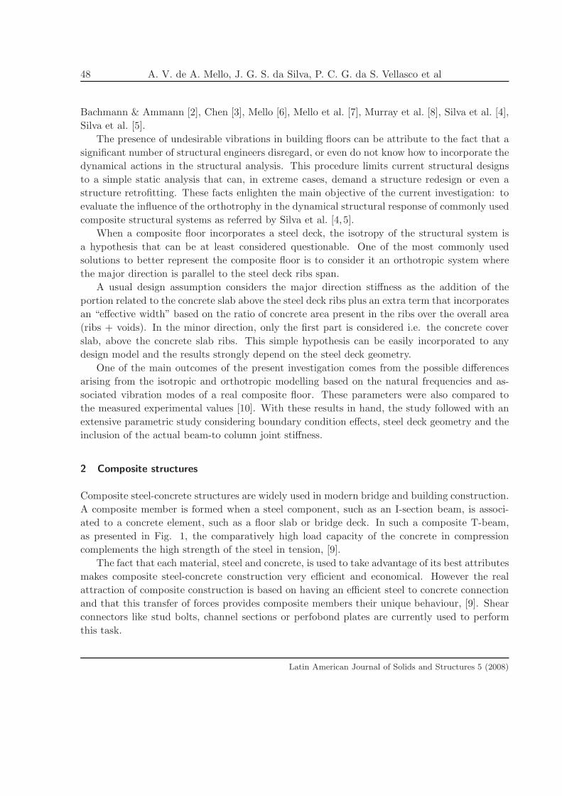
ated to a concrete element, such as a floor slab or bridge deck. In such a composite T-beam,
as presented in Fig. 1, the comparatively high load capacity of the concrete in compression
complements the high strength of the steel in tension, [9].
The fact that each material, steel and concrete, is used to take advantage of its best attributes
makes composite steel-concrete construction very efficient and economical. However the real
attraction of composite construction is based on having an efficient steel to concrete connection
and that this transfer of forces provides composite members their unique behaviour, [9]. Shear
connectors like stud bolts, channel sections or perfobond plates are currently used to perform
this task.
Latin American Journal of Solids and Structures 5 (2008)
Modal analysis of composite floors slabs with profiled steel decks 49�
Figure 1: Composite T-beam.
Nowadays, most of the modern floor systems in buildings use a concrete slab with a cold
formed profiled steel sheeting element (0.8mm thickness) as shown in Fig. 2. This is a spe-
cial form of composite member where the composite action is achieved by embossments in the
sheeting, as presented in Fig. 2, and by some chemical bonding between the concrete and steel
sheeting, [9].
Figure 2: Composite profiled slabs [9].
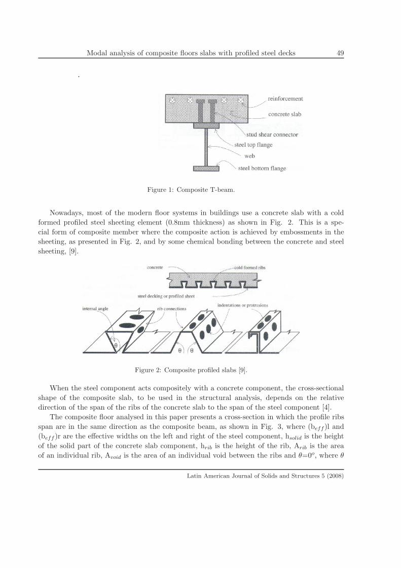
When the steel component acts compositely with a concrete component, the cross-sectional
shape of the composite slab, to be used in the structural analysis, depends on the relative
direction of the span of the ribs of the concrete slab to the span of the steel component [4].
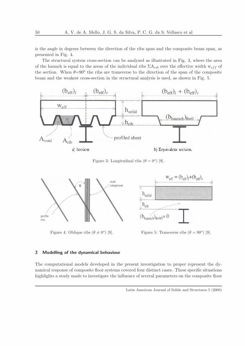
The composite floor analysed in this paper presents a cross-section in which the profile ribs
span are in the same direction as the composite beam, as shown in Fig. 3, where (beff )l and
(beff )r are the effective widths on the left and right of the steel component, hsolid is the height
of the solid part of the concrete slab component, hrib is the height of the rib, Arib is the area
of an individual rib, Avoid is the area of an individual void between the ribs and θ=0o, where θ
Latin American Journal of Solids and Structures 5 (2008)
50 A. V. de A. Mello, J. G. S. da Silva, P. C. G. da S. Vellasco et al
is the angle in degrees between the direction of the ribs span and the composite beam span, as
presented in Fig. 4.
The structural system cross-section can be analysed as illustrated in Fig. 3, where the area
of the haunch is equal to the areas of the individual ribs ΣArib over the effective width weff of
the section. When θ=90o the ribs are transverse to the direction of the span of the composite
beam and the weakest cross-section in the structural analysis is used, as shown in Fig. 5.
�� ������ � �� ������ �������Figure 3: Longitudinal ribs (θ = 0o) [9].
Figure 4: Oblique ribs (θ 6= 0o) [9]. Figure 5: Transverse ribs (θ = 90o) [9].
3 Modelling of the dynamical behaviour
The computational models developed in the present investigation to proper represent the dy-
namical response of composite floor systems covered four distinct cases. These specific situations
highlights a study made to investigate the influence of several parameters on the composite floor
Latin American Journal of Solids and Structures 5 (2008)
Modal analysis of composite floors slabs with profiled steel decks 51
dynamical response like: boundary conditions adopted in modelling, composite system neutral
axis location, steel deck geometry and the actual stiffness provided by the beam to-columns
joints.
These facts motivated the conception of four different models. The first structural model
considers the composite floor systems as simply supported. The second structural model consid-
ers the composite floor system with rigid supports only located at the four floor corners while the
other supports are still considered as simply supported. The third structural model considers
all the supports as being rigid. In these three models the extra stiffness provided by the joints
was not considered.
Finally the fourth model considered the extra stiffness provided by the steel joints. The
effects of the floors above and below the studied composite structural system were taken into
account in this model by considering simply supported 5m length columns.
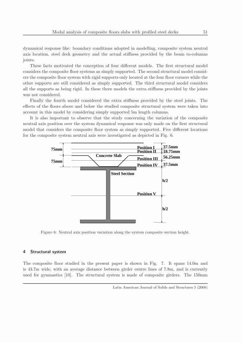
It is also important to observe that the study concerning the variation of the composite
neutral axis position over the system dynamical response was only made on the first structural
model that considers the composite floor system as simply supported. Five different locations
for the composite system neutral axis were investigated as depicted in Fig. 6.
75mm
75mm
37.5mm 18.75mm56.25mm
37.5mm
h/2
h/2
Steel Section
Concrete Slab
Position I
Position III
Position IV
Position V
Position II
Figure 6: Neutral axis position variation along the system composite section height.
4 Structural system
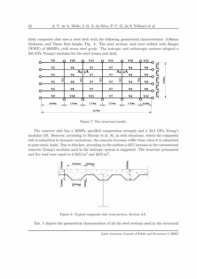
The composite floor studied in the present paper is shown in Fig. 7. It spans 14.0m and
is 43.7m wide, with an average distance between girder centre lines of 7.8m, and is currently
used for gymnastics [10]. The structural system is made of composite girders. The 150mm
Latin American Journal of Solids and Structures 5 (2008)
52 A. V. de A. Mello, J. G. S. da Silva, P. C. G. da S. Vellasco et al
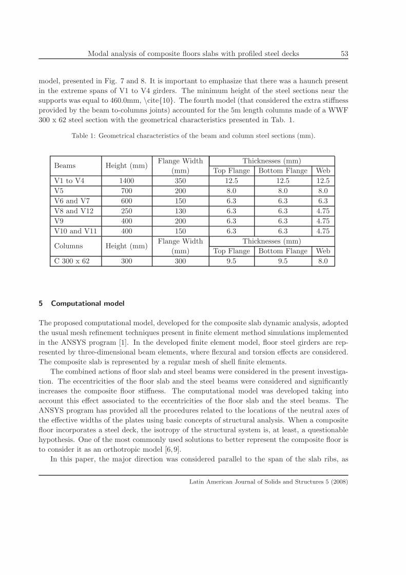
thick composite slab uses a steel deck with the following geometrical characteristics: 0.80mm
thickness, and 75mm flute height, Fig. 8. The steel sections used were welded wide flanges
(WWF) of 300MPa yield stress steel grade. The isotropic and orthotropic systems adopted a
205 GPa Young’s modulus for the steel beams and deck.
7,774m
AA
9,078m 7,774m7,374m
43,70m
V5
V9
V1
V5
V5
V7
V11V10
V6 V7
V7
V7
V7V6
V6
V2
V7
V7V3
V9
V5
V11
V7V6
V10 V11
V7
2,80
mAA
7,374m 4,326m
2,80
m
V6
V6 2,80
m
V8
V12
V4
V6
V6V2
2,80
m
V8
V8 14,0
0m
V10
V6 2,80
m
V12
V8
Figure 7: The structural model.
The concrete slab has a 20MPa specified compression strength and a 23.5 GPa Young’s
modulus [10]. However, according to Murray et al. [8], in such situations, where the composite
slab is submitted to dynamic excitations, the concrete becomes stiffer than when it is submitted
to pure static loads. Due to this fact, according to the authors a 35% increase in the conventional
concrete Young’s modulus used in the isotropic system is suggested. The structure permanent
and live load were equal to 3.5kN/m2 and 2kN/m2.
119,0mm
155,0mm
75,0
mm
75,0
mm
0,8m
m
119,0mm
150,
0mm
Figure 8: Typical composite slab cross-section: Section AA.
Tab. 1 depicts the geometrical characteristics of all the steel sections used in the structural
Latin American Journal of Solids and Structures 5 (2008)
Modal analysis of composite floors slabs with profiled steel decks 53
model, presented in Fig. 7 and 8. It is important to emphasize that there was a haunch present
in the extreme spans of V1 to V4 girders. The minimum height of the steel sections near the
supports was equal to 460.0mm, \cite{10}. The fourth model (that considered the extra stiffness
provided by the beam to-columns joints) accounted for the 5m length columns made of a WWF
300 x 62 steel section with the geometrical characteristics presented in Tab. 1.
Table 1: Geometrical characteristics of the beam and column steel sections (mm).
Beams Height (mm)Flange Width
(mm)
Thicknesses (mm)
Top Flange Bottom Flange Web
V1 to V4 1400 350 12.5 12.5 12.5
V5 700 200 8.0 8.0 8.0
V6 and V7 600 150 6.3 6.3 6.3
V8 and V12 250 130 6.3 6.3 4.75
V9 400 200 6.3 6.3 4.75
V10 and V11 400 150 6.3 6.3 4.75
Columns Height (mm)Flange Width
(mm)
Thicknesses (mm)
Top Flange Bottom Flange Web
C 300 x 62 300 300 9.5 9.5 8.0
5 Computational model
The proposed computational model, developed for the composite slab dynamic analysis, adopted
the usual mesh refinement techniques present in finite element method simulations implemented
in the ANSYS program [1]. In the developed finite element model, floor steel girders are rep-
resented by three-dimensional beam elements, where flexural and torsion effects are considered.
The composite slab is represented by a regular mesh of shell finite elements.
The combined actions of floor slab and steel beams were considered in the present investiga-
tion. The eccentricities of the floor slab and the steel beams were considered and significantly
increases the composite floor stiffness. The computational model was developed taking into
account this effect associated to the eccentricities of the floor slab and the steel beams. The
ANSYS program has provided all the procedures related to the locations of the neutral axes of
the effective widths of the plates using basic concepts of structural analysis. When a composite
floor incorporates a steel deck, the isotropy of the structural system is, at least, a questionable
hypothesis. One of the most commonly used solutions to better represent the composite floor is
to consider it as an orthotropic model [6, 9].
In this paper, the major direction was considered parallel to the span of the slab ribs, as
Latin American Journal of Solids and Structures 5 (2008)
54 A. V. de A. Mello, J. G. S. da Silva, P. C. G. da S. Vellasco et al
presented in Fig. 3. The proposed computational model considers the major direction inertia
as the addition of the part related to the concrete slab above the steel deck ribs plus an extra
term that incorporates an effective width based on the ratio of concrete area present in the ribs
over the overall area (ribs + voids). The minor direction only considers the first part i.e. the
concrete slab above the concrete slab ribs, the so-called cover slab, as shown in Fig. 5.
In order to emulate the orthotropic system, different longitudinal and transverse Young’s
modulus, as well as Poisson ratios, for the concrete slab were used in the major/minor concrete
slab plane directions, as well as in a direction perpendicular to this plane, according to the
system orthotropic inertia characteristics. These values were calculated based on the simple,
but effective, idea of modifying the longitudinal Young’s modulus. Since the concrete inertia
was kept constant in both directions to simplify the model geometry, the Young’s modulus, in
the direction parallel to the deck ribs, was increased. This was made to compensate for the
extra area, and consequently, inertia provided by the concrete present in the deck ribs. With
these results in hand, the transverse Young’s modulus, as well as the Poisson ratios, were also
re-evaluated. This was made accordingly to simple elasticity formulae for orthotropic materials.
The increase in stiffness/resistance provided by the profiled steel sheet was not considered in
the computational model.
The final computational model used 3366 nodes, 726 three-dimensional beam elements,
BEAM44, and 3264 shell elements, SHELL63 [1], leading to a numerical model with 18012
degrees of freedom. The BEAM44 rigid offset capability, [1], was explored to incorporate, in the
structural model, the combined floor beam section eccentricity due to the steel deck.
6 Modal analysis: natural frequencies and vibration modes
The composite floor dynamic response was initially determined through an analysis of its natural
frequencies and vibration modes for the four studied models. The results were obtained through
an extensive parametric study based on finite element simulations made with the already referred
ANSYS program [1]. The natural frequencies and vibration modes were obtained for each model
to identify the most suitable model to represent the investigated composite floor system.
The four distinct computational models were studied aiming to investigate the influence of
several parameters on the composite floor dynamical response like: boundary conditions adopted
in modelling, composite system neutral axis location, steel deck geometry and the actual stiffness
provided by the beam to-columns joints.
The first structural model considers the composite floor supports as simply supported. The
second structural model considers the composite floor supports as rigid supports only at the
four floor corners while the other supports are still considered as simply supported. The third
structural model considers all the support as being rigid.
Finally the fourth model considered the extra stiffness provided by the beam to-columns
joints. The effects of the floors above and below the investigated composite structural sys-
Latin American Journal of Solids and Structures 5 (2008)
Modal analysis of composite floors slabs with profiled steel decks 55
tem were taken into account in this model by considering simply supported five meters length
columns. Tabs. 2 to 9 depict the composite floor natural frequencies (eigenvalues) while the
associated vibration modes (eigenvectors) are presented in Figs. 9 to 14. It is important to
stress that Tabs. 2 to 9 covers numerous steel deck geometries by varying the ratio between the
area of an individual rib, Arib, and the sum, AT , of the areas of a void, Avoid, plus the rib, Arib,
i.e. AT = Arib + Avoid.
Tabs. 2 to 5 also considered the variation of the composite neutral axis position over the
system dynamical response. Five different locations for the composite system neutral axis were
investigated, as depicted in Fig. 6. Due to the space restrictions this paper only presents
the results of the first structural model that considers the composite floor supports as simply
supported. The second and third models used the second position of the composite neutral axis
illustrated in Fig. 6. Tabs. 2 to 9 present the numerical results based on a comparison of the
isotropic and orthotropic models, also quantitatively evaluating the relation between these two
strategies.
7 Results analysis and discussion
7.1 Calibration with the experimental results
The numerical results depicted in Tabs. 2 to 5 (that included the composite system neutral
axis variation) clearly indicated that the results of the first model fundamental frequency agrees
with the experimental test frequency, f01=9.50Hz, referred by Vecci et al. [10]. This fact is the
first step for the validation of the numeric models here presented, as well as the results and
conclusions obtained throughout this investigation.
However, it must be emphasized that, as soon as the boundary conditions change, the com-
posite system vibration modes configurations are modified. Unfortunately, the other composite
floor natural frequency values and the structural system experimental first vibration mode were
not provided in reference [10] for further comparisons with the numerical simulations.
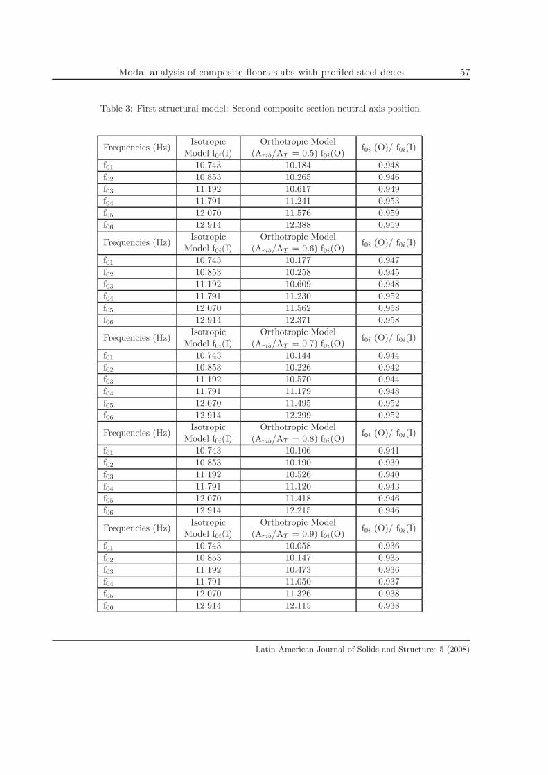
The results, depicted in Tab. 3, for first model where the beam to-columns joints were sim-
ulated by using simple supports f01=10.18Hz, is higher than the experimental value f01=9.50Hz
[10]. This small difference, around 7%, can be probably explained by the fact that the actual
composite system neutral axis is located in a position different from the location assumed in the
numerical analysis.
It should also be observed that the fundamental frequency results depicted in Tabs. 7 to
9 also showed to be in agreement with the first natural frequency experimentally obtained,
f01=9.50Hz, [10]. This was due to the smaller influence of using rigid supports in key points of
the second model, f01=10.24Hz.
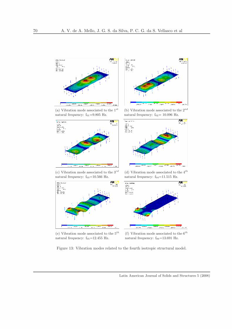
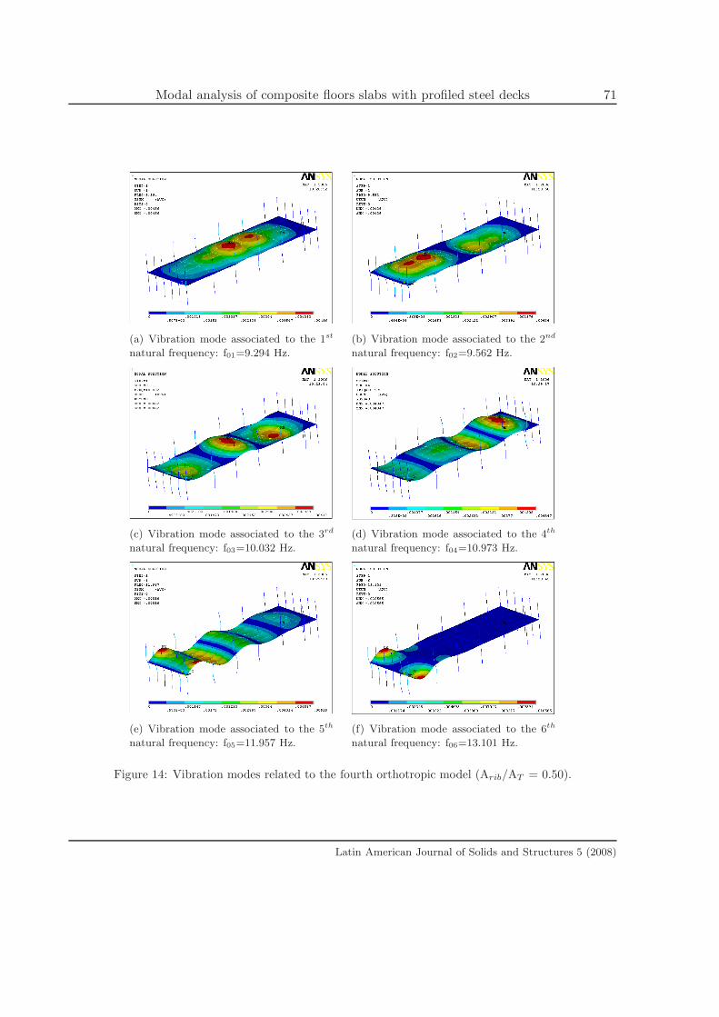
On the other hand, the fourth model that explicitly considered the columns produced a fun-
damental frequency equal to f01=9.30Hz, leading to the best fit with the fundamental frequency
measured experimentally, f01=9.50Hz, [10].
Latin American Journal of Solids and Structures 5 (2008)

56 A. V. de A. Mello, J. G. S. da Silva, P. C. G. da S. Vellasco et al
Table 2: First structural model: First composite section neutral axis position.
Frequencies (Hz)Isotropic
Model f0i(I)
Orthotropic Model
(Arib/AT = 0.5) f0i(O)f0i (O)/ f0i(I)
f01 10.941 10.360 0.947
f02 11.023 10.434 0.947
f03 11.407 10.821 0.949
f04 12.061 11.497 0.953
f05 12.403 11.898 0.959
f06 13.213 12.678 0.960
Frequencies (Hz)Isotropic
Model f0i(I)
Orthotropic Model
(Arib/AT = 0.6) f0i(O)f0i (O)/ f0i(I)
f01 10.941 10.353 0.946
f02 11.023 10.427 0.946
f03 11.407 10.812 0.948
f04 12.061 11.486 0.952
f05 12.403 11.884 0.958
f06 13.213 12.660 0.958
Frequencies (Hz)Isotropic
Model f0i(I)
Orthotropic Model
(Arib/AT = 0.7) f0i(O)f0i (O)/ f0i(I)
f01 10.941 10.322 0.943
f02 11.023 10.393 0.943
f03 11.407 10.773 0.944
f04 12.061 11.434 0.948
f05 12.403 11.815 0.953
f06 13.213 12.586 0.953
Frequencies (Hz)Isotropic
Model f0i(I)
Orthotropic Model
(Arib/AT = 0.8) f0i(O)f0i (O)/ f0i(I)
f01 10.941 10.285 0.940
f02 11.023 10.355 0.939
f03 11.407 10.728 0.940
f04 12.061 11.375 0.943
f05 12.403 11.735 0.946
f06 13.213 12.500 0.946
Frequencies (Hz)Isotropic
Model f0i(I)
Orthotropic Model
(Arib/AT = 0.9) f0i(O)f0i (O)/ f0i(I)
f01 10.941 10.240 0.936
f02 11.023 10.309 0.935
f03 11.407 10.675 0.936
f04 12.061 11.303 0.937
f05 12.403 11.640 0.938
f06 13.213 12.396 0.938
Latin American Journal of Solids and Structures 5 (2008)
Modal analysis of composite floors slabs with profiled steel decks 57
Table 3: First structural model: Second composite section neutral axis position.
Frequencies (Hz)Isotropic
Model f0i(I)
Orthotropic Model
(Arib/AT = 0.5) f0i(O)f0i (O)/ f0i(I)
f01 10.743 10.184 0.948
f02 10.853 10.265 0.946
f03 11.192 10.617 0.949
f04 11.791 11.241 0.953
f05 12.070 11.576 0.959
f06 12.914 12.388 0.959
Frequencies (Hz)Isotropic
Model f0i(I)
Orthotropic Model
(Arib/AT = 0.6) f0i(O)f0i (O)/ f0i(I)
f01 10.743 10.177 0.947
f02 10.853 10.258 0.945
f03 11.192 10.609 0.948
f04 11.791 11.230 0.952
f05 12.070 11.562 0.958
f06 12.914 12.371 0.958
Frequencies (Hz)Isotropic
Model f0i(I)
Orthotropic Model
(Arib/AT = 0.7) f0i(O)f0i (O)/ f0i(I)
f01 10.743 10.144 0.944
f02 10.853 10.226 0.942
f03 11.192 10.570 0.944
f04 11.791 11.179 0.948
f05 12.070 11.495 0.952
f06 12.914 12.299 0.952
Frequencies (Hz)Isotropic
Model f0i(I)
Orthotropic Model
(Arib/AT = 0.8) f0i(O)f0i (O)/ f0i(I)
f01 10.743 10.106 0.941
f02 10.853 10.190 0.939
f03 11.192 10.526 0.940
f04 11.791 11.120 0.943
f05 12.070 11.418 0.946
f06 12.914 12.215 0.946
Frequencies (Hz)Isotropic
Model f0i(I)
Orthotropic Model
(Arib/AT = 0.9) f0i(O)f0i (O)/ f0i(I)
f01 10.743 10.058 0.936
f02 10.853 10.147 0.935
f03 11.192 10.473 0.936
f04 11.791 11.050 0.937
f05 12.070 11.326 0.938
f06 12.914 12.115 0.938
Latin American Journal of Solids and Structures 5 (2008)
58 A. V. de A. Mello, J. G. S. da Silva, P. C. G. da S. Vellasco et al
Finally the fundamental frequency obtained with the third model, see Tab. 8, was equal to
f01=12.05Hz was, as expected, higher than the experimental value, f01=9.50Hz, [10] since all the
model supports were considered rigid.
7.2 Boundary condition influence
Tabs. 3, 7, 8 and 9 indicate that fundamental frequencies were influenced by varying the model
boundary conditions. When the first model natural frequencies, Tab. 3, are compared to the
second and third models, Tabs. 7 and 8, it is possible to observe that as the beam-to-column
joints stiffness is increased (the supports are transformed from simple to rigid) the natural
frequencies also tended to increase. This conclusion is not valid for the fourth model, Tab.
9, since in this case, the natural frequencies were smaller than the previous three models, as
presented in Tab. 3, 7 and 8.
The third model natural frequencies, Tab. 8, were higher than any of the other models. This
is explained by the extremely stiffer beam-to-column joints adopted in modelling being much
higher than the actual composite system frequencies.
These models also served to indicate that modelling the beam-to-column joint as simple
connections, first model, or even rigid connections, second and third models, is not adequate
confirming the joints semi-rigid response. The results of the present investigation suggest that
future investigations should be centred on models that properly represent the actual beam-to-
column joint stiffness like the fourth model. This is clearly seen by the fourth model fundamental
frequency results, 9.3Hz that reached a good agreement with the experiments, 9.5Hz.
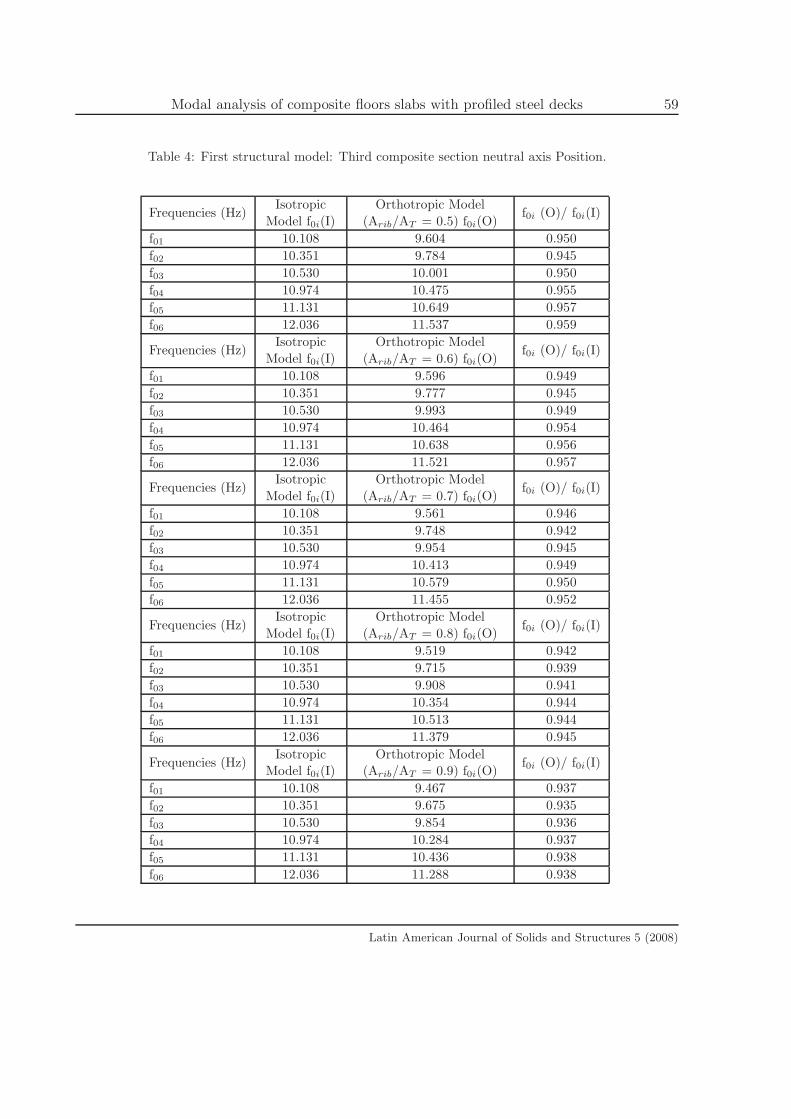
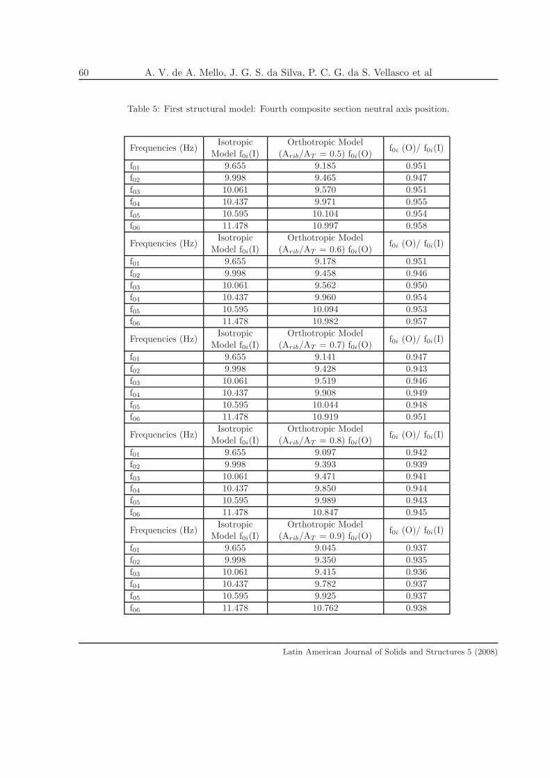
7.3 Composite system neutral axis location influence
The natural frequency results determined with the use of different models, Tabs. 2 to 6, con-
firmed the importance of the correct modelling of the composite system neutral axis location.
As the composite system neutral axis location moves from the first to the fifth position (Fig. 6)
the natural frequency values are significantly reduced.
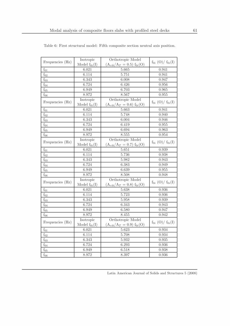
Evidently, this fifth composite system neutral axis location was considered, in the present
study, as a limit situation to establish the natural frequency variation when using the proposed
models. In this case the natural frequency values are, as expected, much lower than any of the
other studied cases, Tab. 6.
7.4 Steel deck geometry influence
Tab. 2 to 9 indicated that in all the cases investigated as the ratio AC/AT increases (meaning
that the concrete area inside the steel deck ribs also increased when compared to the global AT)
from AC/AT=50% up to AC/AT=90% the natural frequency values decrease. This conclusion is
easily understood by the model mass increase associated with a negligible increase of structural
system stiffness.
Latin American Journal of Solids and Structures 5 (2008)
Modal analysis of composite floors slabs with profiled steel decks 59
Table 4: First structural model: Third composite section neutral axis Position.
Frequencies (Hz)Isotropic
Model f0i(I)
Orthotropic Model
(Arib/AT = 0.5) f0i(O)f0i (O)/ f0i(I)
f01 10.108 9.604 0.950
f02 10.351 9.784 0.945
f03 10.530 10.001 0.950
f04 10.974 10.475 0.955
f05 11.131 10.649 0.957
f06 12.036 11.537 0.959
Frequencies (Hz)Isotropic
Model f0i(I)
Orthotropic Model
(Arib/AT = 0.6) f0i(O)f0i (O)/ f0i(I)
f01 10.108 9.596 0.949
f02 10.351 9.777 0.945
f03 10.530 9.993 0.949
f04 10.974 10.464 0.954
f05 11.131 10.638 0.956
f06 12.036 11.521 0.957
Frequencies (Hz)Isotropic
Model f0i(I)
Orthotropic Model
(Arib/AT = 0.7) f0i(O)f0i (O)/ f0i(I)
f01 10.108 9.561 0.946
f02 10.351 9.748 0.942
f03 10.530 9.954 0.945
f04 10.974 10.413 0.949
f05 11.131 10.579 0.950
f06 12.036 11.455 0.952
Frequencies (Hz)Isotropic
Model f0i(I)
Orthotropic Model
(Arib/AT = 0.8) f0i(O)f0i (O)/ f0i(I)
f01 10.108 9.519 0.942
f02 10.351 9.715 0.939
f03 10.530 9.908 0.941
f04 10.974 10.354 0.944
f05 11.131 10.513 0.944
f06 12.036 11.379 0.945
Frequencies (Hz)Isotropic
Model f0i(I)
Orthotropic Model
(Arib/AT = 0.9) f0i(O)f0i (O)/ f0i(I)
f01 10.108 9.467 0.937
f02 10.351 9.675 0.935
f03 10.530 9.854 0.936
f04 10.974 10.284 0.937
f05 11.131 10.436 0.938
f06 12.036 11.288 0.938
Latin American Journal of Solids and Structures 5 (2008)
60 A. V. de A. Mello, J. G. S. da Silva, P. C. G. da S. Vellasco et al
Table 5: First structural model: Fourth composite section neutral axis position.
Frequencies (Hz)Isotropic
Model f0i(I)
Orthotropic Model
(Arib/AT = 0.5) f0i(O)f0i (O)/ f0i(I)
f01 9.655 9.185 0.951
f02 9.998 9.465 0.947
f03 10.061 9.570 0.951
f04 10.437 9.971 0.955
f05 10.595 10.104 0.954
f06 11.478 10.997 0.958
Frequencies (Hz)Isotropic
Model f0i(I)
Orthotropic Model
(Arib/AT = 0.6) f0i(O)f0i (O)/ f0i(I)
f01 9.655 9.178 0.951
f02 9.998 9.458 0.946
f03 10.061 9.562 0.950
f04 10.437 9.960 0.954
f05 10.595 10.094 0.953
f06 11.478 10.982 0.957
Frequencies (Hz)Isotropic
Model f0i(I)
Orthotropic Model
(Arib/AT = 0.7) f0i(O)f0i (O)/ f0i(I)
f01 9.655 9.141 0.947
f02 9.998 9.428 0.943
f03 10.061 9.519 0.946
f04 10.437 9.908 0.949
f05 10.595 10.044 0.948
f06 11.478 10.919 0.951
Frequencies (Hz)Isotropic
Model f0i(I)
Orthotropic Model
(Arib/AT = 0.8) f0i(O)f0i (O)/ f0i(I)
f01 9.655 9.097 0.942
f02 9.998 9.393 0.939
f03 10.061 9.471 0.941
f04 10.437 9.850 0.944
f05 10.595 9.989 0.943
f06 11.478 10.847 0.945
Frequencies (Hz)Isotropic
Model f0i(I)
Orthotropic Model
(Arib/AT = 0.9) f0i(O)f0i (O)/ f0i(I)
f01 9.655 9.045 0.937
f02 9.998 9.350 0.935
f03 10.061 9.415 0.936
f04 10.437 9.782 0.937
f05 10.595 9.925 0.937
f06 11.478 10.762 0.938
Latin American Journal of Solids and Structures 5 (2008)
Modal analysis of composite floors slabs with profiled steel decks 61
Table 6: First structural model: Fifth composite section neutral axis position.
Frequencies (Hz)Isotropic
Model f0i(I)
Orthotropic Model
(Arib/AT = 0.5) f0i(O)f0i (O)/ f0i(I)
f01 6.021 5.665 0.941
f02 6.114 5.751 0.941
f03 6.343 6.008 0.947
f04 6.724 6.426 0.956
f05 6.949 6.703 0.965
f06 8.972 8.567 0.955
Frequencies (Hz)Isotropic
Model f0i(I)
Orthotropic Model
(Arib/AT = 0.6) f0i(O)f0i (O)/ f0i(I)
f01 6.021 5.663 0.941
f02 6.114 5.748 0.940
f03 6.343 6.004 0.946
f04 6.724 6.419 0.955
f05 6.949 6.694 0.963
f06 8.972 8.555 0.954
Frequencies (Hz)Isotropic
Model f0i(I)
Orthotropic Model
(Arib/AT = 0.7) f0i(O)f0i (O)/ f0i(I)
f01 6.021 5.651 0.939
f02 6.114 5.736 0.938
f03 6.343 5.982 0.943
f04 6.724 6.383 0.949
f05 6.949 6.639 0.955
f06 8.972 8.508 0.948
Frequencies (Hz)Isotropic
Model f0i(I)
Orthotropic Model
(Arib/AT = 0.8) f0i(O)f0i (O)/ f0i(I)
f01 6.021 5.638 0.936
f02 6.114 5.723 0.936
f03 6.343 5.958 0.939
f04 6.724 6.343 0.943
f05 6.949 6.580 0.947
f06 8.972 8.455 0.942
Frequencies (Hz)Isotropic
Model f0i(I)
Orthotropic Model
(Arib/AT = 0.9) f0i(O)f0i (O)/ f0i(I)
f01 6.021 5.623 0.934
f02 6.114 5.708 0.934
f03 6.343 5.932 0.935
f04 6.724 6.293 0.936
f05 6.949 6.518 0.938
f06 8.972 8.397 0.936
Latin American Journal of Solids and Structures 5 (2008)

62 A. V. de A. Mello, J. G. S. da Silva, P. C. G. da S. Vellasco et al
Table 7: Second structural model.
Frequencies (Hz)Isotropic
Model f0i(I)
Orthotropic Model
(Arib/AT = 0.5) f0i(O)f0i (O)/ f0i(I)
f01 10.842 10.241 0.945
f02 10.930 10.346 0.947
f03 11.218 10.648 0.949
f04 11.825 11.277 0.954
f05 12.433 11.920 0.959
f06 14.249 13.680 0.960
Frequencies (Hz)Isotropic
Model f0i(I)
Orthotropic Model
(Arib/AT = 0.6) f0i(O)f0i (O)/ f0i(I)
f01 10.842 10.235 0.944
f02 10.930 10.339 0.946
f03 11.218 10.639 0.948
f04 11.825 11.267 0.953
f05 12.433 11.907 0.958
f06 14.249 13.661 0.959
Frequencies (Hz)Isotropic
Model f0i(I)
Orthotropic Model
(Arib/AT = 0.7) f0i(O)f0i (O)/ f0i(I)
f01 10.842 10.206 0.941
f02 10.930 10.308 0.943
f03 11.218 10.600 0.945
f04 11.825 11.214 0.948
f05 12.433 11.839 0.952
f06 14.249 13.578 0.953
Frequencies (Hz)Isotropic
Model f0i(I)
Orthotropic Model
(Arib/AT = 0.8) f0i(O)f0i (O)/ f0i(I)
f01 10.842 10.173 0.938
f02 10.930 10.271 0.940
f03 11.218 10.554 0.941
f04 11.825 11.153 0.943
f05 12.433 11.760 0.946
f06 14.249 13.482 0.946
Frequencies (Hz)Isotropic
Model f0i(I)
Orthotropic Model
(Arib/AT = 0.9) f0i(O)f0i (O)/ f0i(I)
f01 10.842 10.134 0.935
f02 10.930 10.227 0.936
f03 11.218 10.499 0.936
f04 11.825 11.081 0.937
f05 12.433 11.666 0.938
f06 14.249 13.366 0.938
Latin American Journal of Solids and Structures 5 (2008)
Modal analysis of composite floors slabs with profiled steel decks 63
Another important conclusion could be made concerning the relation between the orthotropic
f0i(O), and isotropic f0i(I), models natural frequencies. In all considered cases, Tabs. 2 to 9, the
ratio f0i(O)/f0i(I), only varied from 94% up to 96% of the isotropic model natural frequencies.
This interesting issue indicates, for the analysed structural system, that structural designers do
not necessarily need to consider an orthotropic model to obtain the composite system natural
frequencies, Tabs. 2 to 9.
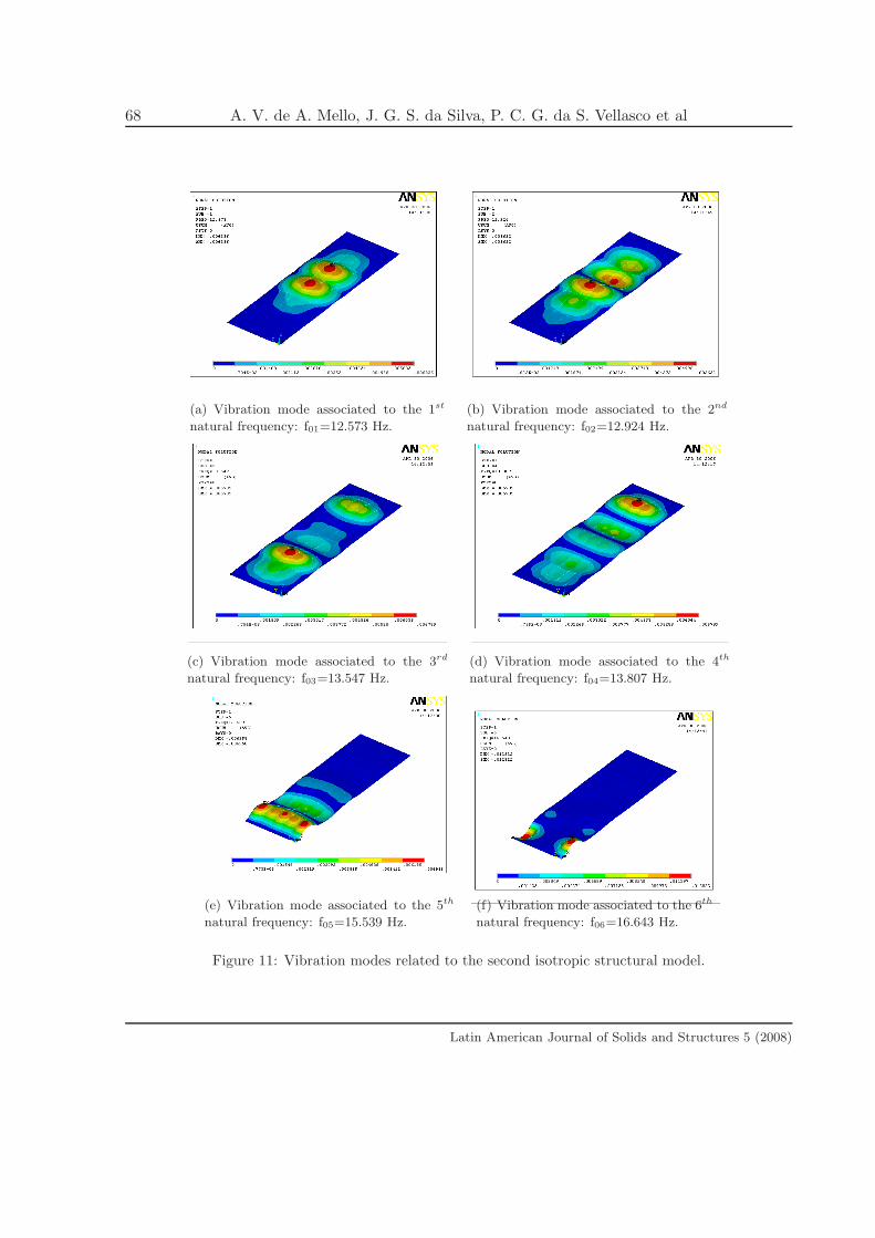
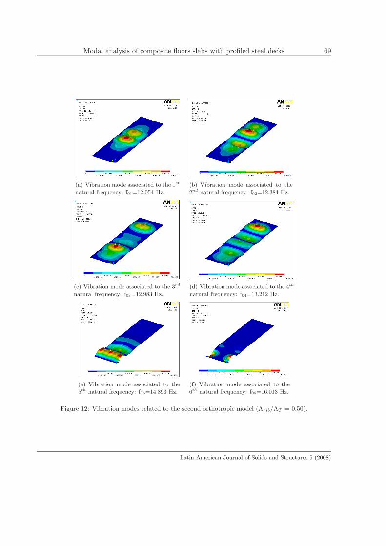
7.5 Vibration mode analysis
The present paper only presents the six first composite system vibration modes using isotropic
and orthotropic solutions (with an associated Arib/AT ratio equal to 0.5) for the first, second
and fourth proposed models, Figs. 9 to 14.
The vibration modes for the various investigated models of the orthotropic system proved to
be qualitatively similar to the vibration modes associated to the isotropic solutions. However,
as the boundary conditions change, from model to model, the composite system vibration mode
configurations are altered. This fact also corroborates the importance of properly modelling
beam-to-column joints in current design practice.
8 Final remarks
This paper presented the evaluation of the structural dynamical behaviour of composite floors
with profiled steel decks. The proposed analysis methodology investigated the linear dynamic
behaviour of a 14m by 43.7m building floor made of a composite slab system with welded wide
flange (WWF) beams and a profiled steel deck.
One of the main objectives of this investigation was to evaluate the orthotrophy effect on
the dynamic response of these composite floors. Four finite element models were developed,
using the ANSYS program [1] to investigate the modelling refinement level on the dynamical
behaviour of the analysed structural system.
The finite element models were developed and refined according to comparisons made be-
tween the numerical and experimental fundamental frequency results. The results obtained
along the present investigation indicated that the effect of some design parameters like: bound-
ary conditions, composite system neutral axis location, steel deck geometry and the actual
stiffness provided by the beam to-columns joints can significantly affect the composite system
natural frequencies.
The investigated structural system presented natural frequencies values that were not sig-
nificantly modified when orthotropic or isotropic models were considered. This fact can be
explained due to the particular structural system geometry in which one of the slab dimensions
is almost three times the other. In this particular case, the orthotrophy effects became signifi-
cantly reduced causing only slight differences on the composite floor natural frequencies values
when compared to the isotropic modelling.
Latin American Journal of Solids and Structures 5 (2008)
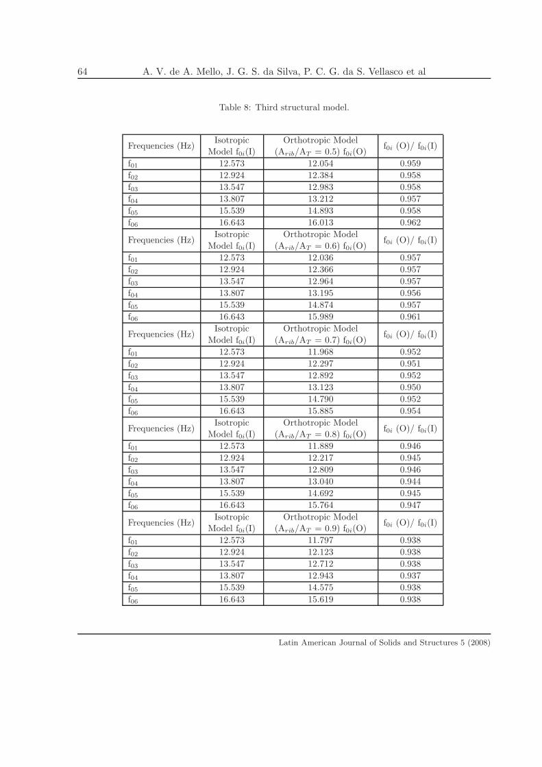
64 A. V. de A. Mello, J. G. S. da Silva, P. C. G. da S. Vellasco et al
Table 8: Third structural model.
Frequencies (Hz)Isotropic
Model f0i(I)
Orthotropic Model
(Arib/AT = 0.5) f0i(O)f0i (O)/ f0i(I)
f01 12.573 12.054 0.959
f02 12.924 12.384 0.958
f03 13.547 12.983 0.958
f04 13.807 13.212 0.957
f05 15.539 14.893 0.958
f06 16.643 16.013 0.962
Frequencies (Hz)Isotropic
Model f0i(I)
Orthotropic Model
(Arib/AT = 0.6) f0i(O)f0i (O)/ f0i(I)
f01 12.573 12.036 0.957
f02 12.924 12.366 0.957
f03 13.547 12.964 0.957
f04 13.807 13.195 0.956
f05 15.539 14.874 0.957
f06 16.643 15.989 0.961
Frequencies (Hz)Isotropic
Model f0i(I)
Orthotropic Model
(Arib/AT = 0.7) f0i(O)f0i (O)/ f0i(I)
f01 12.573 11.968 0.952
f02 12.924 12.297 0.951
f03 13.547 12.892 0.952
f04 13.807 13.123 0.950
f05 15.539 14.790 0.952
f06 16.643 15.885 0.954
Frequencies (Hz)Isotropic
Model f0i(I)
Orthotropic Model
(Arib/AT = 0.8) f0i(O)f0i (O)/ f0i(I)
f01 12.573 11.889 0.946
f02 12.924 12.217 0.945
f03 13.547 12.809 0.946
f04 13.807 13.040 0.944
f05 15.539 14.692 0.945
f06 16.643 15.764 0.947
Frequencies (Hz)Isotropic
Model f0i(I)
Orthotropic Model
(Arib/AT = 0.9) f0i(O)f0i (O)/ f0i(I)
f01 12.573 11.797 0.938
f02 12.924 12.123 0.938
f03 13.547 12.712 0.938
f04 13.807 12.943 0.937
f05 15.539 14.575 0.938
f06 16.643 15.619 0.938
Latin American Journal of Solids and Structures 5 (2008)
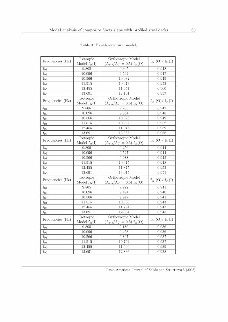
Modal analysis of composite floors slabs with profiled steel decks 65
Table 9: Fourth structural model.
Frequencies (Hz)Isotropic
Model f0i(I)
Orthotropic Model
(Arib/AT = 0.5) f0i(O)f0i (O)/ f0i(I)
f01 9.805 9.305 0.948
f02 10.096 9.562 0.947
f03 10.566 10.032 0.949
f04 11.515 10.973 0.953
f05 12.455 11.957 0.960
f06 13.691 13.101 0.957
Frequencies (Hz)Isotropic
Model f0i(I)
Orthotropic Model
(Arib/AT = 0.5) f0i(O)f0i (O)/ f0i(I)
f01 9.805 9.285 0.947
f02 10.096 9.554 0.946
f03 10.566 10.023 0.949
f04 11.515 10.962 0.952
f05 12.455 11.943 0.959
f06 13.691 13.085 0.956
Frequencies (Hz)Isotropic
Model f0i(I)
Orthotropic Model
(Arib/AT = 0.5) f0i(O)f0i (O)/ f0i(I)
f01 9.805 9.256 0.944
f02 10.096 9.527 0.944
f03 10.566 9.988 0.945
f04 11.515 10.915 0.948
f05 12.455 11.875 0.953
f06 13.691 13.015 0.951
Frequencies (Hz)Isotropic
Model f0i(I)
Orthotropic Model
(Arib/AT = 0.5) f0i(O)f0i (O)/ f0i(I)
f01 9.805 9.222 0.941
f02 10.096 9.494 0.940
f03 10.566 9.947 0.941
f04 11.515 10.860 0.943
f05 12.455 11.794 0.947
f06 13.691 12.934 0.945
Frequencies (Hz)Isotropic
Model f0i(I)
Orthotropic Model
(Arib/AT = 0.5) f0i(O)f0i (O)/ f0i(I)
f01 9.805 9.180 0.936
f02 10.096 9.453 0.936
f03 10.566 9.897 0.937
f04 11.515 10.794 0.937
f05 12.455 11.696 0.939
f06 13.691 12.836 0.938
Latin American Journal of Solids and Structures 5 (2008)
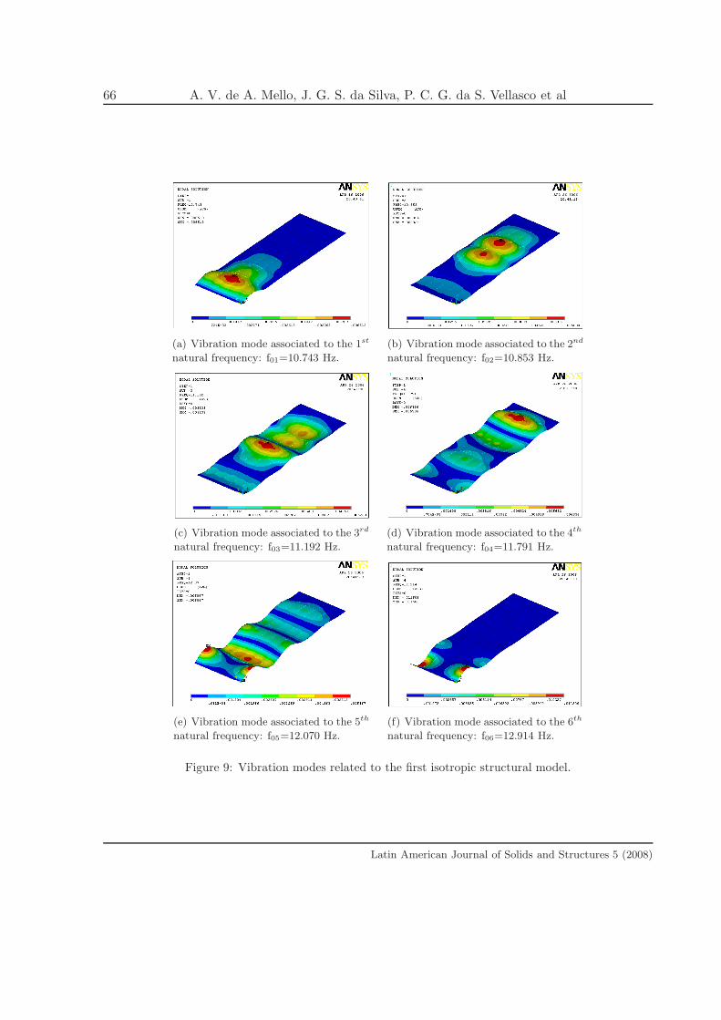
66 A. V. de A. Mello, J. G. S. da Silva, P. C. G. da S. Vellasco et al
(a) Vibration mode associated to the 1st
natural frequency: f01=10.743 Hz.
(b) Vibration mode associated to the 2nd
natural frequency: f02=10.853 Hz.
(c) Vibration mode associated to the 3rd
natural frequency: f03=11.192 Hz.
(d) Vibration mode associated to the 4th
natural frequency: f04=11.791 Hz.
(e) Vibration mode associated to the 5th
natural frequency: f05=12.070 Hz.
(f) Vibration mode associated to the 6th
natural frequency: f06=12.914 Hz.
Figure 9: Vibration modes related to the first isotropic structural model.
Latin American Journal of Solids and Structures 5 (2008)
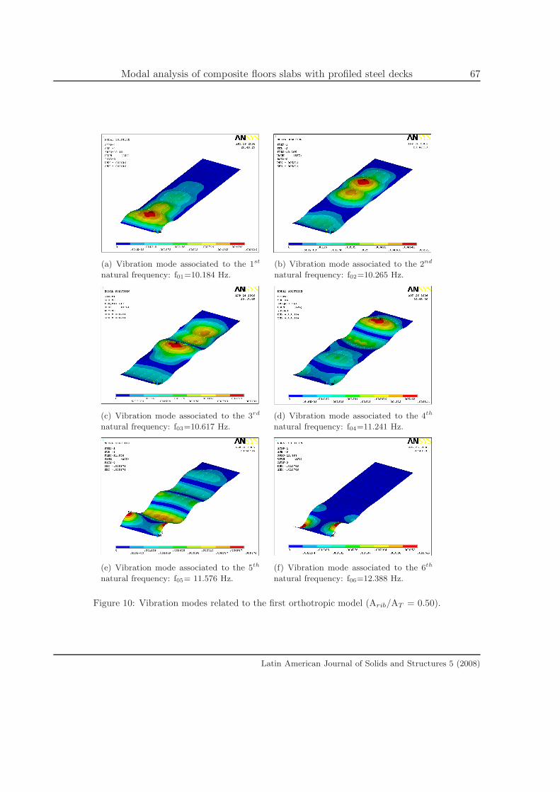
Modal analysis of composite floors slabs with profiled steel decks 67
(a) Vibration mode associated to the 1st
natural frequency: f01=10.184 Hz.
(b) Vibration mode associated to the 2nd
natural frequency: f02=10.265 Hz.
(c) Vibration mode associated to the 3rd
natural frequency: f03=10.617 Hz.
(d) Vibration mode associated to the 4th
natural frequency: f04=11.241 Hz.
(e) Vibration mode associated to the 5th
natural frequency: f05= 11.576 Hz.
(f) Vibration mode associated to the 6th
natural frequency: f06=12.388 Hz.
Figure 10: Vibration modes related to the first orthotropic model (Arib/AT = 0.50).
Latin American Journal of Solids and Structures 5 (2008)
68 A. V. de A. Mello, J. G. S. da Silva, P. C. G. da S. Vellasco et al
(a) Vibration mode associated to the 1st
natural frequency: f01=12.573 Hz.
(b) Vibration mode associated to the 2nd
natural frequency: f02=12.924 Hz.
(c) Vibration mode associated to the 3rd
natural frequency: f03=13.547 Hz.
(d) Vibration mode associated to the 4th
natural frequency: f04=13.807 Hz.
(e) Vibration mode associated to the 5th
natural frequency: f05=15.539 Hz.
(f) Vibration mode associated to the 6th
natural frequency: f06=16.643 Hz.
Figure 11: Vibration modes related to the second isotropic structural model.
Latin American Journal of Solids and Structures 5 (2008)
Modal analysis of composite floors slabs with profiled steel decks 69
(a) Vibration mode associated to the 1st
natural frequency: f01=12.054 Hz.
(b) Vibration mode associated to the
2nd natural frequency: f02=12.384 Hz.
(c) Vibration mode associated to the 3rd
natural frequency: f03=12.983 Hz.
(d) Vibration mode associated to the 4th
natural frequency: f04=13.212 Hz.
(e) Vibration mode associated to the
5th natural frequency: f05=14.893 Hz.
(f) Vibration mode associated to the
6th natural frequency: f06=16.013 Hz.
Figure 12: Vibration modes related to the second orthotropic model (Arib/AT = 0.50).
Latin American Journal of Solids and Structures 5 (2008)
70 A. V. de A. Mello, J. G. S. da Silva, P. C. G. da S. Vellasco et al
(a) Vibration mode associated to the 1st
natural frequency: f01=9.805 Hz.
(b) Vibration mode associated to the 2nd
natural frequency: f02= 10.096 Hz.
(c) Vibration mode associated to the 3rd
natural frequency: f03=10.566 Hz.
(d) Vibration mode associated to the 4th
natural frequency: f04=11.515 Hz.
(e) Vibration mode associated to the 5th
natural frequency: f05=12.455 Hz.
(f) Vibration mode associated to the 6th
natural frequency: f06=13.691 Hz.
Figure 13: Vibration modes related to the fourth isotropic structural model.
Latin American Journal of Solids and Structures 5 (2008)
Modal analysis of composite floors slabs with profiled steel decks 71
(a) Vibration mode associated to the 1st
natural frequency: f01=9.294 Hz.
(b) Vibration mode associated to the 2nd
natural frequency: f02=9.562 Hz.
(c) Vibration mode associated to the 3rd
natural frequency: f03=10.032 Hz.
(d) Vibration mode associated to the 4th
natural frequency: f04=10.973 Hz.
(e) Vibration mode associated to the 5th
natural frequency: f05=11.957 Hz.
(f) Vibration mode associated to the 6th
natural frequency: f06=13.101 Hz.
Figure 14: Vibration modes related to the fourth orthotropic model (Arib/AT = 0.50).
Latin American Journal of Solids and Structures 5 (2008)
72 A. V. de A. Mello, J. G. S. da Silva, P. C. G. da S. Vellasco et al
The adopted steel deck profile was not sufficient to induce a significant orthotrophy charac-
teristic to the investigated composite slab system. This was reflected on the vibration modes
for the various investigated models of the orthotropic system that were qualitatively similar to
the vibration modes associated to the isotropic solutions. However, as soon as the boundary
conditions change, the composite system vibration modes configurations are modified.
The results and conclusions of the present study suggest the continuation of an extensive
parametric study considering design parameters like the beam-to-column joint modelling, pri-
mary and secondary girder spans, geometrical characteristics of the steel sections and the con-
crete slab and alternative structural systems.
Acknowledgments
The authors would like to thank the financial support provided by the National and State
Scientific and Technological Agencies: CNPq, CAPES and FAPERJ.
References
[1] Inc. ANSYS, Swanson analysis systems. Basic analysis procedures. P.O. Box 65, Johnson Road,
Houston, PA, 15342-0065, 2 edition, 1998. version 5.5.
[2] H. Bachmann and W. Ammann. Vibrations in structures induced by man and machines. IABSE
Structural Engineering Document 3E, International Association for Bridges and Structural Engi-
neering, 1987. ISBN 3-85748-052-X.
[3] Y. Chen. Finite element analysis for walking vibration problems for composite precast building floors
using adina: modelling; simulation, and comparison. Computers & Structures, 72:109–126, 1999.
[4] J. G. S. da Silva, F. J. da C. P. Soeiro, P. C. G. da S. Vellasco, Andrade S. A. L de, and R. N.
Werneck. Dynamical analysis of composite steel decks floors subjected to rhythmic load actions. In
8th International Conference on Civil and Structural Engineering Computing, CIVIL COMP-2001,
Austria, 2001. CD-ROM, 16 pages.
[5] J. G. S. da Silva, F. J. da C. P. Soeiro, P. C. G. da S. Vellasco, Andrade S. A. L de, and R. N. Werneck.
Dynamical response of steel deck composite slabs with geometric orthotrophy subjected to human
rhythmic activities. In 6th International Conference on Computational Structures Technology, CST
2002, Praga, 2002. CD-ROM, 17 pages.
[6] A. V. de A. Mello. Vibracoes em pisos de edificacoes induzidas por atividades humanas. Master’s
thesis, Programa de Pos-Graduacao em Engenharia Civil – PGECIV, Universidade do Estado do
Rio de Janeiro, UERJ, Rio de Janeiro, Brasil, 2005. (in Portuguese).
[7] A. V. de A. Mello, J. G. S. da Silva, and L. R. O. de Lima. Analise de pisos de edificacoes submetidos
a acoes dinamicas provenientes do caminhar humano. CILAMCE XXVI, Iberian Latin American
Congress on Computational Methods in Engineering, 2005. CD-ROM, 14 pages (in Portuguese).
[8] T. M. Murray, D. E. Allen, and E. E. Ungar. Floor vibrations due to human activity. Steel Design
Guide Series, 11th Steel Design Guide Series, American Institute of Steel Construction, AISC, 1997.
Latin American Journal of Solids and Structures 5 (2008)

Modal analysis of composite floors slabs with profiled steel decks 73
[9] D. J. Oehlers and M. A. Bradford. Elementary Behaviour of Composite Steel & Concrete Structural
Members. Butterworth-Heinemann, London, UK, 1999.
[10] M. A. M. Vecci, R. H. Fakury, and P. V. P. Mendonca. Analise de vibracoes de pisos submetidos
a excitacoes rıtmicas. aplicacao de criterios para conforto em edificacoes. In Encontro Nacional
de Conforto no Ambiente Construıdo. III Encontro Latino-Amercano de Conforto no Ambiente
Construıdo. Brasil, pages 1–6. (in Portuguese), 1999.
Latin American Journal of Solids and Structures 5 (2008)