Embed Size (px)
Citation preview

User’s Manual MOD9200D MODBUS Transceiver

MOD9200 MODBUS Gateway Programming Software
AUTOMATION COMPONENTS, INC Version : 0.2 2305 Pleasant View Road I0000676 Middleton, Wisconsin 53562 Page 2 of 38 www.workaci.com (888) 967-5224
License Agreement for Automation Components, Inc. Software IMPORTANT-READ THESE TERMS CAREFULLY BEFORE INSTALLING THIS SOFTWARE. THESE TERMS AND CONDITIONS ESTABLISH A CONTRACT BETWEEN YOU INDIVIDUALLY IF YOU ARE AGREEING TO IT IN YOUR OWN CAPACITY, OR IF YOU ARE AUTHORIZED TO AGREE ON BEHALF OF YOUR COMPANY OR ANOTHER ORGANIZATION, BETWEEN THE ENTITIY FOR WHOSE BENEFIT YOU ACT (“YOU”), AND ACI. BY INSTALLING THIS SOFTWARE PACKAGE, YOU ACKNOWLEDGE THAT YOU HAVE READ THIS LICENSE AGREEMENT, THAT YOU UNDERSTAND IT, AND THAT YOU AGREE TO BE BOUND BY ITS TERMS. IF YOU DO NOT AGREE TO THE TERMS AND CONDITIONS OF THIS LICENSE AGREEMENT OR IF YOU DO NOT UNDERSTAND THEM, PROMPTLY RETURN THE UNOPENED PACKAGE AND ALL ACCOMPANYING ITEMS TO ACI FOR A FULL REFUND. 1. Grant of License for Registered Users
ACI grants you a non-exclusive, non-transferable license to use the software program with which this license is distributed (the "Product"), including any documentation files accompanying the Product ("Documentation") on any single computer. You may use the Product on a second computer so long as only one (1) is used at a time. 2. Backup Copy
You may make one backup copy of the Product. You may use it only to reinstall the Product. 3. Ownership
You have no ownership rights in the Product. Rather, you have a license to use the Product as long as this License Agreement remains in full force and effect. Ownership of the Product, Documentation and all intellectual property rights therein shall remain at all times with ACI. Any use of the Product by any other person, business, corporation, government organization or any other entity is strictly forbidden and is a violation of this License Agreement. You may not make more copies of the Product than specified in this agreement or allowed by applicable law, despite this limitation; publish the Product for others to copy; or rent, lease or lend the Product. 4. Copyright
The Product and Documentation contain material that is protected by United States Copyright Law as well as other intellectual property law and international treaty provisions. All rights not granted to you herein are expressly reserved by ACI. You may not remove any proprietary notice of ACI from any copy of the Product or Documentation. 5. Restrictions
You may not publish, display, disclose, rent, lease, modify, loan, distribute, or create derivative works based on the Product or any part thereof. You may not reverse engineer, decompile, translate, adapt, or disassemble the Product, nor shall you attempt to create the source code from the object code for the Product. You may not transmit the Product over any network or between any devices, although you may use the Product to make such transmissions of other materials. You may access the Product from only one computer at a time. 6. Limited Warranty
ACI WARRANTS THAT THE PRODUCT WILL OPERATE SUBSTANTIALLY IN ACCORDANCE WITH THE THEN CURRENT DOCUMENTATION. SHOULD THE PRODUCT NOT SO OPERATE, YOUR EXCLUSIVE REMEDY, AND ACI'S SOLE OBLIGATION UNDER THIS WARRANTY, SHALL BE, AT ACI'S SOLE DISCRETION, CORRECTION OF THE DEFECT OR REFUND OF LICENSE FEES PAID BY YOU FOR THE PERIOD DURING WHICH THE DEFECT WAS NOT CORRECTED AND MATERIALLY AFFECTED THE OPERATION OF THE PRODUCT. ANY USE BY YOU OF THE PRODUCT IS AT YOUR OWN RISK. THIS LIMITED WARRANTY IS THE ONLY WARRANTY PROVIDED BY ACI REGARDING THE PRODUCT. EXCEPT FOR THE LIMITED WARRANTY ABOVE, THE PRODUCT IS PROVIDED "AS IS." TO THE MAXIMUM EXTENT PERMITTED BY LAW, ACI DISCLAIMS ALL OTHER WARRANTIES OF ANY KIND, EITHER EXPRESSED OR IMPLIED, INCLUDING, WITHOUT LIMITATION, IMPLIED WARRANTIES OF MERCHANTABILITY AND FITNESS FOR A PARTICULAR PURPOSE. ACI DOES NOT WARRANT THAT THE FUNCTIONS CONTAINED IN THE PRODUCT WILL MEET ANY REQUIREMENTS OR NEEDS YOU MAY HAVE, OR THAT THE PRODUCT WILL OPERATE ERROR FREE, OR IN AN UNINTER-RUPTED FASHION, OR THAT ANY DEFECTS OR ERRORS IN THE PRODUCT WILL BE CORRECTED, OR THAT THE PRODUCT IS COMPATIBLE WITH ANY PARTICULAR PLATFORM. SOME JURISDICTIONS DO NOT ALLOW THE WAIVER OR EXCLUSION OF IMPLIED WARRANTIES SO THEY MAY NOT APPLY TO YOU. 7. Limitation of Liability
IN NO EVENT WILL ACI BE LIABLE TO YOU OR ANY THIRD PARTY FOR ANY INCIDENTAL OR CONSEQUENTIAL DAMAGES (INCLUDING, WITHOUT LIMITATION, INDIRECT, SPECIAL, PUNITIVE, OR EXEMPLARY DAMAGES FOR LOSS OF BUSINESS, LOSS OF PROFITS, BUSINESS INTERRUPTION, OR LOSS OF BUSINESS INFORMATION) ARISING OUT OF THE USE OF OR INABILITY TO USE THE PROGRAM, OR FOR ANY CLAIM BY ANY OTHER PARTY, EVEN IF ACI HAS BEEN ADVISED OF THE POSSIBILITY OF SUCH DAMAGES. ACI’S AGGREGATE LIABILITY WITH RESPECT TO ITS OBLIGATIONS UNDER THIS AGREEMENT OR OTHERWISE WITH RESPECT TO THE PRODUCT AND DOCUMENTATION OR OTHERWISE SHALL NOT EXCEED THE AMOUNT OF THE LICENSE FEE PAID BY YOU FOR THE PRODUCT AND DOCUMENTATION. BECAUSE SOME STATES/COUNTRIES DO NOT ALLOW THE EXCLUSION OR LIMITATION OF LIABILITY FOR CONSEQUENTIAL OR INCIDENTAL DAMAGES, THE ABOVE LIMITATION MAY NOT APPLY TO YOU. 8. Export Restrictions
THIS LICENSE AGREEMENT IS EXPRESSLY MADE SUBJECT TO ANY LAWS, REGULATIONS, ORDERS, OR OTHER RESTRICTIONS ON THE EXPORT FROM THE UNITED STATES OF AMERICA OF THE PRODUCT OR INFORMATION ABOUT SUCH PRODUCT WHICH MAY BE IMPOSED FROM TIME TO TIME BY THE GOVERNMENT OF THE UNITED STATES OF AMERICA. YOU SHALL NOT EXPORT THE PRODUCT, DOCUMENTATION, OR INFORMATION ABOUT THE PRODUCT AND DOCUMENTATION WITHOUT CONSENT OF ACI AND COMPLIANCE WITH SUCH LAWS, REGULATIONS, ORDERS, OR OTHER RESTRICTIONS. 9. Termination
This License Agreement is effective until it is terminated. You may terminate this License Agreement at any time by destroying or returning to ACI all copies of the Product and Documentation in your possession or under your control. ACI may terminate this License Agreement for any reason, including, but not limited to, if ACI finds that you have violated any of the terms of this License Agreement. Upon notification of termination, you agree to destroy or return to ACI all copies of the Product and Documentation and to certify in writing that all known copies, including backup copies, have been destroyed. All provisions relating to confidentiality, proprietary rights, and non-disclosure shall survive the termination of this Product License Agreement. Additionally, it is understood that termination of this Agreement will not affect a refund of any license fees paid or owed to ACI. 10. General
This License Agreement shall be construed, interpreted and governed by the laws of the State of Wisconsin without regard to conflicts of law provisions thereof. The exclusive forum for any disputes arising out of or relating to this License Agreement shall be an appropriate federal or state court sitting in the State of Wisconsin, USA. This License Agreement shall constitute the entire Agreement between the parties hereto. Any waiver or modification of this License Agreement shall only be effective if it is in writing and signed by both parties hereto. If any part of this License Agreement is found invalid or unenforceable by a court of competent jurisdiction, the remainder of this License Agreement shall be interpreted so as to reasonably effect the intention of the parties.
MOD9200 MODBUS Gateway Programming Software
AUTOMATION COMPONENTS, INC Version : 0.2 2305 Pleasant View Road I0000676 Middleton, Wisconsin 53562 Page 3 of 38 www.workaci.com (888) 967-5224
Table of Contents I. Introduction ….......................................................................................................... 4
a. MOD9200 Gateway System ………………………………….……………… 4
II. MODBUS Transceiver Installation & Network Setup …………………….….. 5 a. Transceiver Installation ……………………………………..………………. 5 b. Network Setup ……………………………………………………................. 6 c. Setting A New IP Address …………………………………..…………….…. 6 d. Manually Resetting The Factory Default IP Address ……….…………….. 8
III. Configuration Software ……………………………………………………….…. 9
a. Configuration Software Description ……………………………………..…. 9 b. System Requirements …………………………………………………...…… 9 c. Configuration Software Installation ………………………….…………….. 9 d. Creating A MODBUS Configuration File …………………………………..10 e. Input Register Configuration …………………………….…………………. 11 f. Digital Output (Coil) Register Configuration ……………………….…..….16 g. Analog Output (Holding) Register Configuration ………………………… 18 h. Setting the Mesh Network ID for the repeater/router devices …………… 21 i. Miscellaneous Menu …………………………………………………………. 21 j. Configuring The Gateway For TCP/IP MODBUS …………………….…. 23 k. Configuring The Gateway For RS485/RS232 RTU/ASCII MODBUS ….. 24 l. Sending The Configuration File To The MOD9200 …………………....…. 28 m. Activating The Configuration File ……………………………………..…... 30
IV. Data Acquisition …………………………………………………………………. 32
a. MODBUS Standard …………………………………………………………. 32 b. MOD9200D MODBUS Transceiver Application Parameters ……….…… 32
• The Input Registers …………………………………………………….... 33 • The Digital Output (Coil) Registers …………………………………….. 34 • The Analog Output (Holding) Registers …...………………………...… 34 • The Alarm Registers …………...………………………………………... 34
V. Quick Setup Instructions …………………………………………...…………… 37
a. Installing The MOD9200 MODBUS Gateway …………………………….. 37 b. Installing The MOD9200 Configuration Software …………………………37

MOD9200 MODBUS Gateway Programming Software
AUTOMATION COMPONENTS, INC Version : 0.2 2305 Pleasant View Road I0000676 Middleton, Wisconsin 53562 Page 4 of 38 www.workaci.com (888) 967-5224
I. Introduction
MOD9200 MODBUS Gateway
The MOD9200 MODBUS network receiver utilizes reliable Spread Spectrum Mesh Network Radio technology. When used with other wireless sensors the system can transmit remote sensor readings, status/alarm indications and control signals to a centralized networked monitoring station or controller without the need for extensive wiring. The MOD9200 is compatible with any control system or Programmable Logic Controller (PLC) panel that utilizes the TCP/IP or RS485/RS232 RTU/ASCII MODBUS communication protocols.
a. MOD9200 Gateway System
• MOD9200 MODBUS Network Receiver • Receives input from up to 50 remote wireless sensor modules and/or wireless
output modules (RD2402 & RD2432) per Transceiver • Signal repeater/router(RR2552) can be used to extend the wireless sensor
transmission distance if needed • Ethernet Network Connection or RS485/RS232 Connection • MOD9200 Configuration Software
Wireless Wall Temp. & Humidity Sensor
Wireless Remote Digital/Analog Input Modules & Energy Totalizer
Wireless Immersion & Remote Sensors
Wireless Outside Air Temperature & Humidity
MODBUS Network
MOD9200D MODBUS Transceivers
Repeater Increases Transmission Distance, if
needed
Wireless Digital (Relay) Outputs
Wireless Digital
& Analog Outputs
Sub-System Overview

MOD9200 MODBUS Gateway Programming Software
AUTOMATION COMPONENTS, INC Version : 0.2 2305 Pleasant View Road I0000676 Middleton, Wisconsin 53562 Page 5 of 38 www.workaci.com (888) 967-5224
II. MODBUS Transceiver Installation & Network Setup
a. Transceiver Installation
• Choose a location close to the computer, network hub or RS485 loop.
• Mount the gateway on the wall using four #8 screws.
• 24 VAC Input - Connect 24VAC 60 Hz and earth ground to the input terminals using 18 AWG wire as shown in the product data sheet.
• TCP/IP - If using TCP/IP use RJ45 Category 5 Ethernet cable to connect the
Gateway (J2) to the network hub or computer. (See Figure 1).
• RS232 - If using RS232 RTU/ASCII use the MOD9200-RS232 cable (sold separately) to connect the Gateway (J1) to the serial port on the computer (See Figure 1).
Figure 1
• RS485 - If using RS485 RTU/ASCII use 18 gauge shielded twisted pair wire to connect the Gateway (Terminals A+ & B-) to the MODBUS master. When running the RS485 loop into a breaker panel use wire with appropriate insulation for the voltage present (See Figure 1).
Default IP
Jumper
TCP/IP Connection (J2)
Connection (J2)
24 VAC Input
RS485 Terminals

MOD9200 MODBUS Gateway Programming Software
AUTOMATION COMPONENTS, INC Version : 0.2 2305 Pleasant View Road I0000676 Middleton, Wisconsin 53562 Page 6 of 38 www.workaci.com (888) 967-5224
• Multiple RS485 Devices - If more than one RS485 device is used, the devices should be “daisy chained” or “straight-line connected” by connecting all the “A” wires to the “A” terminals and the “B” wires to the “B” terminals. Do not use spur lines or a star configuration.
• RS485 Terminating Resistor - If the MOD9200 is at the end of a RS485 loop a terminating resistor should be installed to match the electrical impedance characteristic of the twisted pair loop and prevent signal echoes from corrupting the data.
b. Network Setup
• (Note: Even if you are planning to use the RS485 RTU/ASCII MODBUS protocol option, a network connection or crossover cable is required during the initial setup of the gateway for transporting the Gateway Configuration File via FTP)
• Connect the MOD9200 Gateway to a 10/100Base-T Ethernet network or use a crossover cable to connect directly to the PC.
Note: Only (1) TCP/IP connection is allowed at a time – either a MODBUS Polling Master or the Programmer Configuration Tool – DO NOT try to use both at the same time.
• Apply 24 VAC 60 Hz power to the MOD9200 Gateway.
c. Setting A New IP Address
• The MOD9200 is shipped from the factory with an IP address of 192.168.0.1 and a subnet mask of 255.255.255.0 .
Note: To initially connect to the Gateway, the networked PC must have a static IP address in the form of 192.168.0.X where X is > 1 with a subnet mask of 255.255.255.0.
• The IP Address is changed by changing the IP Address in the Gateway Config File. Open either an existing config file or a new config file using the Programmer Software.

MOD9200 MODBUS Gateway Programming Software
AUTOMATION COMPONENTS, INC Version : 0.2 2305 Pleasant View Road I0000676 Middleton, Wisconsin 53562 Page 7 of 38 www.workaci.com (888) 967-5224
• Click on Settings > TCP/IP Transport.
• Enter the new IP Address and Subnet Mask and click OK. The new IP Address will take affect when the Config File is downloaded to the Gateway.
• Router Setup – Webserver : Do not Use

MOD9200 MODBUS Gateway Programming Software
AUTOMATION COMPONENTS, INC Version : 0.2 2305 Pleasant View Road I0000676 Middleton, Wisconsin 53562 Page 8 of 38 www.workaci.com (888) 967-5224
d. Manually Resetting The Factory Default IP Address
• The Gateway can manually be reset to the default IP Address by moving the jumper (J6) from “Norm” to “Init”.
• Turn off the power to the Gateway and move the jumper from “Norm” to “Init”.
Turn on power and the Gateway can be communicated with using the Factory Default IP Address 192.168.0.1 Subnet Mask 255.255.255.0. The Config File is no longer active while the jumper is in the “Init” position . A new Config File can be downloaded to the Gateway if desired.
• To reactivate the Config File - turn off the power to the Gateway and move the jumper back to “Norm”. Turn the power back on and the Config File will become active. The Gateway will have the IP Address that was set in the Config File.
• TCP/IP APPLICATION NOTE: When using the MOD9200D in TCP/IP mode, the MODBUS Master “polling interval” should be set to occur within 2 minutes 59 seconds or less. If no polling activity occurs within 3 minutes the MOD9200D will automatically close the network connection and the MODBUS Master will have to close and re-open the connection to re-establish communications. The MODBUS Master should not attempt to re-open the network connection for at least 3 ½ minutes after the network connection has been closed. ---- Only (1) TCP/IP connection is allowed at a time.

MOD9200 MODBUS Gateway Programming Software
AUTOMATION COMPONENTS, INC Version : 0.2 2305 Pleasant View Road I0000676 Middleton, Wisconsin 53562 Page 9 of 38 www.workaci.com (888) 967-5224
III. Configuration Software
a. Configuration Software Description
• The MODBUS data registers of the Gateway need to be configured prior to use.
The configuration program “SETUP.exe” can be found on the disk or CD ROM on the back cover of this manual will configure the data register as follows:
- Assign the Input Register function – Analog or Discrete - Assign wireless Digital Output (Coil) Register function - Assign wireless Analog Output (Holding) Register function - Assign the register address - Assign the Wireless Sensor ID and transmission channel - Assign the data type
• The MOD9200 Transceiver can have up to 100 (addresses 0 to 99) data registers configured to be either Analog or Discrete, 50 digital outputs and 50 analog outputs.
• Error registers are directly mapped to the data registers + 400 (addresses 400 to 499). For example errors for data register 55 will be in error register 455.
b. System Requirements
• PC (Notebook or desktop) with Windows 98, XP, Vista or Windows 7
• Ethernet connection
• 10 MB of hard drive memory available
c. Configuration Software Installation
• If other applications are running, close them before inserting the ConfigTool CD into the CD ROM Drive. The Programmer setup program should automatically start running. Follow the on screen instructions to complete the installation.
• If the Programmer setup program does not start automatically click on Start > Run > Browse and click on the Programmer CD ROM. Double click on “setup.exe”. Follow the on screen instructions to complete the installation.

MOD9200 MODBUS Gateway Programming Software
AUTOMATION COMPONENTS, INC Version : 0.2 2305 Pleasant View Road I0000676 Middleton, Wisconsin 53562 Page 10 of 38 www.workaci.com (888) 967-5224
d. Creating A MODBUS Configuration File
• To create a new MOD9200 configuration file open the Programmer by clicking on Start > Programs > Trs Programmer 6.XX.
• To open a new configuration table Click on File > New Gateway File. A blank configuration table will open.
• The default startup is the Input Register configuration table and System Setup page.
• By clicking the “RegisterBank” tab, you can go to the Digital Output (Coil)
register configuration table or Analog Output (Holding) Register configuration table.

MOD9200 MODBUS Gateway Programming Software
AUTOMATION COMPONENTS, INC Version : 0.2 2305 Pleasant View Road I0000676 Middleton, Wisconsin 53562 Page 11 of 38 www.workaci.com (888) 967-5224
e. Input Register Configuration
• Each row of the configuration table is a unique data register having 8 special attributes.
REG FUNCTION
REG ADDRESS
GROUP NAME
POINT NAME
TRANSMITTER ID
TRANS CHAN
DATA FORMAT
LOG
-- Identifies the function of the register – Analog or Digital (Discrete) Note: If selecting the Digital (Discrete) function be sure to set the appropriate Digital Capture Time (Page 15)
-- Assigns the address of the data register (0 to 99).
Automatically assigns the address of the error register (400 to 499 i.e. data register address + 400)
-- Assigns a group name to the data register. Multiple data
registers can have the same group name. This is useful for monitoring and data logging programs.
-- Assigns a unique name to the data register to help identify
the location of the sensor/transmitter. Multiple point names can have the same group name.
-- Assigns a wireless sensor/transmitter address to the data
register. Each wireless sensor is factory configured with a unique hexadecimal address.
-- Assigns a wireless sensor/transmitter data channel to the data
register. A wireless sensor/transmitter may have up to four (4) analog channels and (4) digital status/alarm channels.
-- Assigns the data type to the register – temperature (RTD or
Thermistor 20K), analog voltage, totalizer or humidity. This register is left blank if the REG FUNCTION is Digital (Discrete).
-- Obsolete Function.

MOD9200 MODBUS Gateway Programming Software
AUTOMATION COMPONENTS, INC Version : 0.2 2305 Pleasant View Road I0000676 Middleton, Wisconsin 53562 Page 12 of 38 www.workaci.com (888) 967-5224
• First we will assign the REG FUNCTION by clicking in the REG FUNCTION cell to open a drop down menu. Select the appropriate function.
• Use the mouse to move to the next column to assign the REG ADDRESS by clicking in the cell. When the “RegisterEntry, AutoSet” is turned on, REG ADDRESS is automatically filled with the next sequential number from 0 to 99.
• Again use the mouse to move to the next column. Enter a GROUP NAME for the data set by typing the group name in the cell. Enter the name in the cell by using the mouse to click on the next column.
Note: DO NOT use delimiters - , ; : < > [ ] { } ( ) / \ - in the Group Name.

MOD9200 MODBUS Gateway Programming Software
AUTOMATION COMPONENTS, INC Version : 0.2 2305 Pleasant View Road I0000676 Middleton, Wisconsin 53562 Page 13 of 38 www.workaci.com (888) 967-5224
• Enter a POINT NAME for the data point by typing the name in the cell. Enter the name in the cell by using the mouse to click on the next column.
Note: DO NOT use delimiters in the Point Name.
• Assign a sensor/transmitter to the data register by clicking in the TRANSMITTER ID cell to open a drop down menu. Use the scroll bar to scroll to the correct address or automatically scroll to the address by typing the hexadecimal address in the cell. To select the address, click on the appropriate ID in the drop down menu. Each transmitter is factory configured with a unique ID – refer to the sensor product data sheet for the location of the transmitter ID.

MOD9200 MODBUS Gateway Programming Software
AUTOMATION COMPONENTS, INC Version : 0.2 2305 Pleasant View Road I0000676 Middleton, Wisconsin 53562 Page 14 of 38 www.workaci.com (888) 967-5224
• Assign the appropriate sensor transmission channel to the data register by clicking in the cell to open a drop down menu. Click on the appropriate transmission channel (01 to 04) to select.
• The active transmission channels are factory configured as follows:
Device
Analog CH-01
Analog CH-02
Digital CH-01 WT2630A
Space Temp (Therm 20K)
WT2630B
Space Temp (Therm 20K)
SetPoint (Analog)
Override (Discrete) See page 15 to set the Digital Capture Time
WT2630C
Space Temp (Therm 20K)
Override (Discrete) See page 15 to set the Digital Capture Time
WH2630A Humidity
WH2630B
Space Temp (Therm 20K)
Humidity
OA2630A
Outdoor Temp (Therm 20K)
Outdoor Humidity
OST2630A
Outdoor Temp (Therm 20K)
DT2630A
Duct Temperature (Therm 20K)
DT2650A Ave Temperature (Therm 20K)
DH2630A
Duct Humidity
DH2630B
Duct Temperature (Therm 20K)
Duct Humidity
FT2630A
Fluid Temperature (Therm 20K)
RT2630A,B,C
See Device Label for Analog (4) and Digital (4) Configuration RT2620A
See Device Label for Digital (4) Configuration
RT2602B Digital (2) Inputs SST2630A
Temperature (Therm 20K)
SST5630AE
Temperature (RTD 1K)

MOD9200 MODBUS Gateway Programming Software
AUTOMATION COMPONENTS, INC Version : 0.2 2305 Pleasant View Road I0000676 Middleton, Wisconsin 53562 Page 15 of 38 www.workaci.com (888) 967-5224
• Select the appropriate DATA FORMAT value by clicking in the cell to open a
drop down menu.
• To create a new data register row, click on Row > Append. Continue to do this for each row/data register that needs to be configured.
• The completed configuration example for an office building is as follows:
• The columns may be resized by placing the cursor over one side of the column. When the cursor changes to two arrows hold down the left mouse button and drag the side of the column to resize it.

MOD9200 MODBUS Gateway Programming Software
AUTOMATION COMPONENTS, INC Version : 0.2 2305 Pleasant View Road I0000676 Middleton, Wisconsin 53562 Page 16 of 38 www.workaci.com (888) 967-5224
f. Digital Output (Coil) Register Configuration
• Select the Digital Output (Coil) Register table by clicking the “RegisterBank” tab.
• First we will assign the REG ADDRESS by clicking in the cell. Before entering register addresses, ensure the “RegisterEntry” AutoSet is turned off as shown:
• Enter the Register address in the REG ADDRESS window. The valid range is 0 to 49.

MOD9200 MODBUS Gateway Programming Software
AUTOMATION COMPONENTS, INC Version : 0.2 2305 Pleasant View Road I0000676 Middleton, Wisconsin 53562 Page 17 of 38 www.workaci.com (888) 967-5224
• Again use the mouse to move to the next column. Enter a GROUP NAME, if desired, for the data set by typing the group name in the cell. Enter the name in the cell by using the mouse to click on the next column.
Note: DO NOT use commas or semicolons in the Group Name.
• Enter a POINT NAME, if desired, for the data point by typing the name in the cell. Enter the name in the cell by using the mouse to click on the next column.
Note: DO NOT use commas or semicolons in the Point Name.
• Assign a sensor/transmitter to the data register by clicking in the TRANSMITTER ID cell to open a drop down menu. This is the device ID of the remote output devices (RD2402 & RD2432). Use the scroll bar to scroll to the correct address or automatically scroll to the address by typing the hexadecimal address in the cell. To select the address click on the appropriate ID in the drop down menu.

MOD9200 MODBUS Gateway Programming Software
AUTOMATION COMPONENTS, INC Version : 0.2 2305 Pleasant View Road I0000676 Middleton, Wisconsin 53562 Page 18 of 38 www.workaci.com (888) 967-5224
• Assign the appropriate digital or relay output “TRANS CHAN” to the data register by clicking in the cell to open a drop down menu. Click on the appropriate transmission channel (01 to 04) to select.
• The active transmission channels or output number are factory set as follows:
Device
Digital
Analog
RD2402
1 to 2 for relay #1 and relay #2
NA
Wireless relay output module
RD2432
1 to 4 for relay #1 to relay #4
1 to 4 for analog output 1 to 4
Wireless digital & analog output module
g. Analog Output (Holding) Register Configuration
• Select the Analog Output (Holding) Register table by clicking the “RegisterBank” tab.

MOD9200 MODBUS Gateway Programming Software
AUTOMATION COMPONENTS, INC Version : 0.2 2305 Pleasant View Road I0000676 Middleton, Wisconsin 53562 Page 19 of 38 www.workaci.com (888) 967-5224
• First we will assign the REG ADDRESS by clicking in the cell. Before
entering register addresses, ensure the “RegisterEntry” AutoSet is turned off as shown:
• Enter the Register address in the REG ADDRESS window. The valid range is 0 to 49.
• Again use the mouse to move to the next column. Enter a GROUP NAME, if desired, for the data set by typing the group name in the cell.
Enter the name in the cell by using the mouse to click on the next column.
Note: DO NOT use commas or semicolons in the Group Name.

MOD9200 MODBUS Gateway Programming Software
AUTOMATION COMPONENTS, INC Version : 0.2 2305 Pleasant View Road I0000676 Middleton, Wisconsin 53562 Page 20 of 38 www.workaci.com (888) 967-5224
• Enter a POINT NAME, if desired, for the data point by typing the name in the cell. Enter the name in the cell by using the mouse to click on the next column. Note: DO NOT use commas or semicolons in the Point Name.
• Assign a sensor/transmitter to the data register by clicking in the TRANSMITTER ID cell to open a drop down menu. This is the device ID of the remote output devices (RD2432). Use the scroll bar to scroll to the correct address or automatically scroll to the address by typing the hexadecimal address in the cell. To select the address click on the appropriate ID in the drop down menu.
• Assign the appropriate digital or relay output “TRANS CHAN” to the data register by clicking in the cell to open a drop down menu. Click on the appropriate transmission channel (01 to 04) to select.

MOD9200 MODBUS Gateway Programming Software
AUTOMATION COMPONENTS, INC Version : 0.2 2305 Pleasant View Road I0000676 Middleton, Wisconsin 53562 Page 21 of 38 www.workaci.com (888) 967-5224
• The active transmission channels or output number are factory set as follows:
Device
Digital
Analog
RD2402
1 to 2 for relay #1 and relay #2
NA
Wireless relay output module
RD2432
1 to 4 for relay #1 to relay #4
1 to 4 for analog output 1 to 4
Wireless digital & analog output module
h. Setting the Mesh Network ID for the repeater/router devices
• The mesh network ID of the MOD9200 Gateway can be set to specific network # from 1 to 64. The MOD9200 functions as a network coordinator. Any repeater/router that has the same network ID will be able to communicate and channel sensor information to the MOD9200
i. Miscellaneous Menu
• The transmitter timeout interval, default temperature degrees (C/F), and Digital Input Capture Time are set globally for all sensors using the Miscellaneous Dialog Screen.
• Click on Settings > Miscellaneous

MOD9200 MODBUS Gateway Programming Software
AUTOMATION COMPONENTS, INC Version : 0.2 2305 Pleasant View Road I0000676 Middleton, Wisconsin 53562 Page 22 of 38 www.workaci.com (888) 967-5224
• Set the transmitter transmission timeout interval (requires a minimum of 30 min.) by clicking in the Transmitter Timeout cell to open a drop down menu. Use the scroll bar to scroll down to the appropriate value (1 to 60 min.) or type the value in the cell to automatically scroll to the appropriate value. This will be used to generate an error message if the transmitter fails to transmit in the specified time interval.
• To select the timeout interval click on the appropriate value in the drop down menu.
• The Digital Input Capture Time can be set to hold a momentary contact
closure such as the override button on the WT2630B/C for a period of time
(Default is 0 min. & recommended value is 1 min.) so the controller has time to recognize the contact closure.
• The Digital Capture Time can be set up to 240 minutes (4 hours) in applications where an extended period of time is needed such as “unoccupied period by-pass”.
• Set the Digital Capture Time interval (seconds or minutes) by clicking on “Seconds” or “Minutes”. Click in the Digital Capture Time cell to open a drop down menu. Use the scroll bar to scroll down to the appropriate value (0 to 240) or type the value in the cell to automatically scroll to the appropriate value. To select the timeout interval click on the appropriate value in the drop down menu.
• Digital Scaling On check box – Should be “UNCHECKED”. Check only when configuring the MOD9200BNT BACnet® receiver or the MOD9200LON LonWorks® Receiver.

MOD9200 MODBUS Gateway Programming Software
AUTOMATION COMPONENTS, INC Version : 0.2 2305 Pleasant View Road I0000676 Middleton, Wisconsin 53562 Page 23 of 38 www.workaci.com (888) 967-5224
• Units - Select the appropriate default temperature scale F/C.
• Register Value When Sensor Lost – The user has the options to select whether the sensor value should remain unchanged or set to 19999 when the communication link is lost with the sensor (after the transmitter timeout period).
j. Configuring The Gateway For TCP/IP MODBUS
• Click on the menu Comm > TCP/IP to select the TCP/IP configuration menu.
• Type in the appropriate IP address and click “OK”. The TCP/IP transport protocol is automatically setup.

MOD9200 MODBUS Gateway Programming Software
AUTOMATION COMPONENTS, INC Version : 0.2 2305 Pleasant View Road I0000676 Middleton, Wisconsin 53562 Page 24 of 38 www.workaci.com (888) 967-5224
k. Configuring The Gateway For RS485/RS232 RTU/ASCII MODBUS Protocol
• When using the MODBUS Serial Line communications protocol the Gateway needs to be assigned a unique Identifier (Slave) Address to differentiate it from other serial devices on the network. To enter the Gateway Unit ID (Slave Address) into the Configuration File click on the Menu Comm > Unit Identifier.
• Click on the drop down menu arrow and select the Gateway Unit ID from the drop down menu and click “OK”. The default Unit ID is “1”.
• Click on Menu - Comm > Serial Transport to activate the Serial Comm Port dialog box.

MOD9200 MODBUS Gateway Programming Software
AUTOMATION COMPONENTS, INC Version : 0.2 2305 Pleasant View Road I0000676 Middleton, Wisconsin 53562 Page 25 of 38 www.workaci.com (888) 967-5224
• Use the Serial Comm Port configuration dialog box to select the appropriate internal communication parameters (Connect Speed, Connect Preferences, and Transport Mode) for the Transceiver.
• There are two different serial transmission modes defined in MODBUS – the
RTU mode and the ASCII mode. They define the bit contents of the message fields transmitted serially on the line and determine how information is packed into the message fields and decoded.
• The MOD9200 transmission mode and serial port parameters need to be exactly the same as those configured for the Master.
• Select the Maximum Speed - In the Serial Comm Port configuration window
click on the drop down selection arrow and select the Maximum Speed for communication – speeds range from 9600 bps to 38400 bps.
• Communications speed needs to be the same as in the Master configuration.
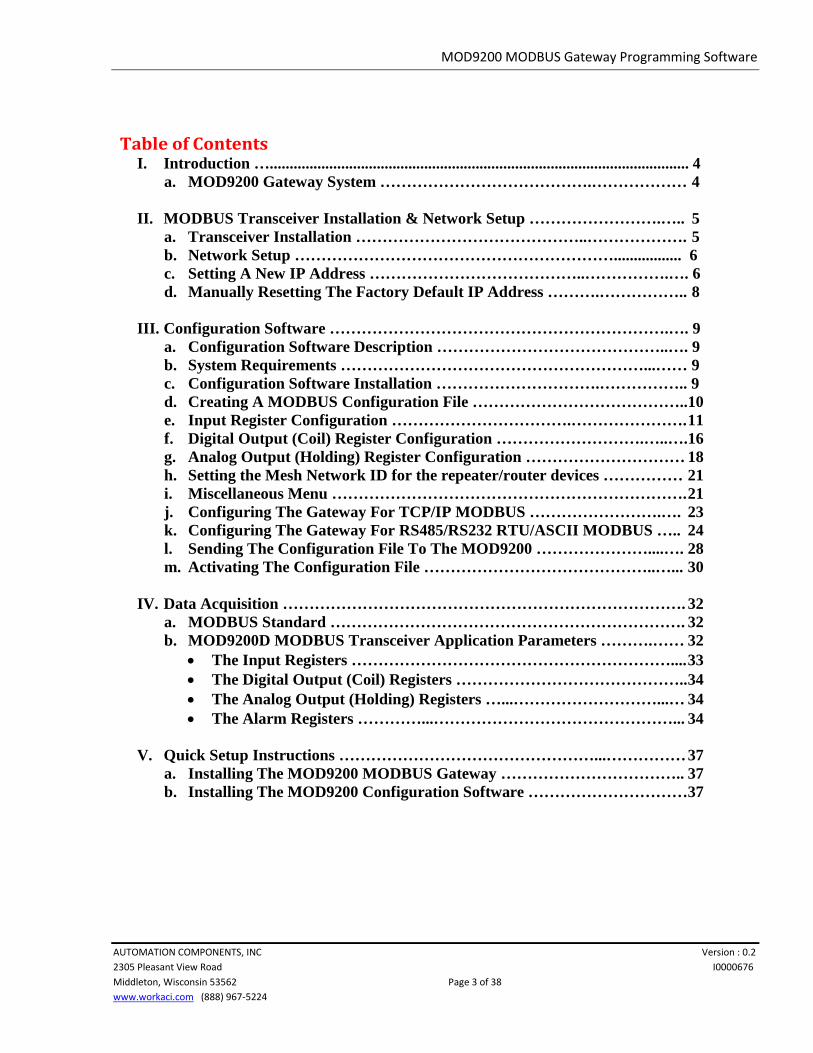
• Select the number of Data Bits – click on the selection arrow and select either 7 or 8 bits. The RTU transport mode requires 8 bits. Standard ASCII transport mode requires 7 bits and Extended ASCII requires 8 bits.
MOD9200 MODBUS Gateway Programming Software
AUTOMATION COMPONENTS, INC Version : 0.2 2305 Pleasant View Road I0000676 Middleton, Wisconsin 53562 Page 26 of 38 www.workaci.com (888) 967-5224
• The number of Data Bits needs to be the same as in the Master configuration.
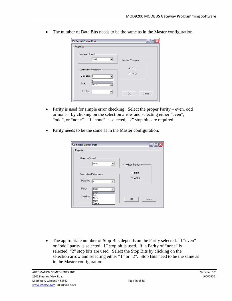
• Parity is used for simple error checking. Select the proper Parity – even, odd or none – by clicking on the selection arrow and selecting either “even”, “odd”, or “none”. If “none” is selected, “2” stop bits are required.
• Parity needs to be the same as in the Master configuration.
• The appropriate number of Stop Bits depends on the Parity selected. If “even” or “odd” parity is selected “1” stop bit is used. If a Parity of “none” is selected, “2” stop bits are used. Select the Stop Bits by clicking on the selection arrow and selecting either “1” or “2”. Stop Bits need to be the same as in the Master configuration.
MOD9200 MODBUS Gateway Programming Software
AUTOMATION COMPONENTS, INC Version : 0.2 2305 Pleasant View Road I0000676 Middleton, Wisconsin 53562 Page 27 of 38 www.workaci.com (888) 967-5224
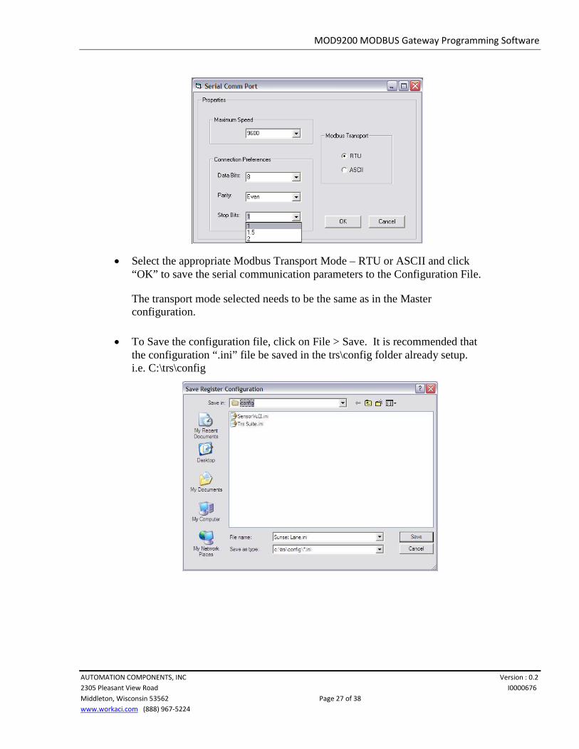
• Select the appropriate Modbus Transport Mode – RTU or ASCII and click “OK” to save the serial communication parameters to the Configuration File.
The transport mode selected needs to be the same as in the Master configuration.
• To Save the configuration file, click on File > Save. It is recommended that the configuration “.ini” file be saved in the trs\config folder already setup. i.e. C:\trs\config

MOD9200 MODBUS Gateway Programming Software
AUTOMATION COMPONENTS, INC Version : 0.2 2305 Pleasant View Road I0000676 Middleton, Wisconsin 53562 Page 28 of 38 www.workaci.com (888) 967-5224
l. Sending The Configuration File To The MOD9200
• Note: Even if you are planning to use the RS485 RTU/ASCII MODBUS protocol option a network connection or crossover cable is required during the initial setup of the gateway for transporting the Gateway Configuration File via FTP
• Always Save the configuration file to the folder “trs\config” before sending it to the MOD9200 Gateway.
• To send the new configuration file to the MOD9200 Gateway click on File >
File Transfer and a dialog box will appear.
MOD9200 MODBUS Gateway Programming Software
AUTOMATION COMPONENTS, INC Version : 0.2 2305 Pleasant View Road I0000676 Middleton, Wisconsin 53562 Page 29 of 38 www.workaci.com (888) 967-5224
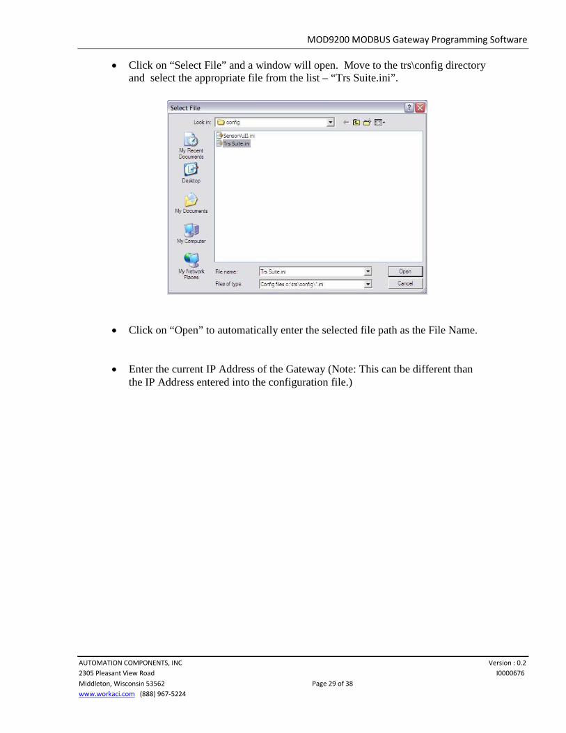
• Click on “Select File” and a window will open. Move to the trs\config directory and select the appropriate file from the list – “Trs Suite.ini”.
• Click on “Open” to automatically enter the selected file path as the File Name.
• Enter the current IP Address of the Gateway (Note: This can be different than the IP Address entered into the configuration file.)

MOD9200 MODBUS Gateway Programming Software
AUTOMATION COMPONENTS, INC Version : 0.2 2305 Pleasant View Road I0000676 Middleton, Wisconsin 53562 Page 30 of 38 www.workaci.com (888) 967-5224
• Click on “Connect” and the status of the connection will be displayed in the Comm Status window. When the Gateway is connected click on “Send File” to the send the config file to the Gateway.
m. Activating The Config File
• Once the config file has been sent to the Gateway it will become active immediately. If you have changed the IP Address in the config file you will lose your connection and have to reconnect using the IP Address and Subnet Mask that was sent in the new config file.

MOD9200 MODBUS Gateway Programming Software
AUTOMATION COMPONENTS, INC Version : 0.2 2305 Pleasant View Road I0000676 Middleton, Wisconsin 53562 Page 31 of 38 www.workaci.com (888) 967-5224
• To confirm that the appropriate configuration file is saved on the Gateway – reopen the File Transfer Dialog and click on “Get File” to retrieve a copy of the active configuration file from the Gateway. The Editor will automatically save this file in the folder “trs\config” with the file name of “ _config.ini”.
• Click on File > Open Config File and select the “_config.ini” file. Click on “Open” to open the file in the Editor. Confirm that the file is the same as the original configuration file.
• NOTE: The “_config.ini” file is a dynamic file. If multiple MOD9200 Gateways are being administered from the same PC the “_config.ini” file will be a copy of the configuration file from the last Gateway administered.

MOD9200 MODBUS Gateway Programming Software
AUTOMATION COMPONENTS, INC Version : 0.2 2305 Pleasant View Road I0000676 Middleton, Wisconsin 53562 Page 32 of 38 www.workaci.com (888) 967-5224
IV. Data Acquisition
a. MODBUS Standard
• MODBUS is an application layer messaging protocol for client/server communication between devices connected on different types of buses or networks.
• The MOD9200 functions as a MODBUS Server in the MODBUS
Client/Server Model and utilizes the MODBUS messaging services over TCP/IP or RS485/RS232 to communicate to a MODBUS Client.
• For implementation information please refer to the Modbus Standard Library at www.modbus.org . Both the MODBUS Application Protocol Specification and the MODBUS Messaging On TCP/IP Implementation Guide are available for download there.
b. MOD9200D MODBUS Transceiver Application Parameters
• When interfacing 3rd party monitoring software or controllers to the MOD9200 Gateway, be sure to set the appropriate MOD9200 Gateway Unit Identifier (see page 18) and for TCP/IP connect to the MOD9200 Gateway Port: 0502. If either the Serial RTU mode or Serial ASCII mode are used connect through the appropriate COM serial port.
• TCP/IP APPLICATION NOTE: When using the MOD9200D in TCP/IP mode the MODBUS Master “polling interval” should be set to occur within 2 minutes 59 seconds or less. If no polling activity occurs within 3 minutes the MOD9200D will automatically close the network connection and the MODBUS Master will have to close and re-open the connection to re-establish communications. The MODBUS Master should not attempt to re-open the network connection for at least 3 ½ minutes after the network connection has been closed. ----Only (1) TCP/IP connection is allowed at a time.
• The MOD9200 MODBUS Gateway receives data from up to fifty (50) wireless sensors and updates its data registers on a real time basis.

MOD9200 MODBUS Gateway Programming Software
AUTOMATION COMPONENTS, INC Version : 0.2 2305 Pleasant View Road I0000676 Middleton, Wisconsin 53562 Page 33 of 38 www.workaci.com (888) 967-5224
• Input/Output Configuration Map:
- Analog and Digital Inputs: Programmer Software Input Register 00 to 99 –to- MODBUS Input Register 30001 to 30100
- Digital (Relay) Outputs: Programmer Software Digital Output (Coil) Register 00 to 49 –to-MODBUS Coil Register 01 to 50
- Analog Outputs: Programmer Software Analog Output (Holding) Register 00 to 49 –to- MODBUS Holding Register 40001 to 40050
• The Input Registers
- The MODBUS Input Register 30001 to 30100 are used to receiver all sensor inputs.
- All wireless sensor information (analog and discrete input) will be displayed as numeric values.
- All digital status/alarms will be received and stored by MOD9200 as 1 or 0 (1=input contact closed & 0=input contact open). The Digital Capture Time can be set to “hold” momentary contact closures long enough to be “picked up by the system”.
- The Digital Capture Time can be set up to 240 minutes (4 hours) in applications where an extended period of time is needed such as “unoccupied period by-pass”.
- All analog data will be received and stored as integer values. For data types THERM 20k, RTD 1k, RTD 1k Ext, and HUMIDITY the least significant digit of the integer value is the decimal number (i.e. 8000 will mean 800.0).
- For the data type ANALOG there is no decimal and data is displayed in counts (0 to 4095). For example the setpoint pot of the WT2630B is setup as an ANALOG data type with ranges from “0” (Cool) to “4095” (Warm).
- For the data type TOTALIZER there is no decimal and data is displayed in counts (24 bits). When the count reaches 16,777,215 (24 bits) the count value rolls over to 0 and begins again.

MOD9200 MODBUS Gateway Programming Software
AUTOMATION COMPONENTS, INC Version : 0.2 2305 Pleasant View Road I0000676 Middleton, Wisconsin 53562 Page 34 of 38 www.workaci.com (888) 967-5224
• The Digital Output (Coil) Registers
- The MODBUS Coil Register 01 to 50 are used for command remote wireless digital outputs (relays) module i.e. RD2402D & the RD2432D devices. Values to be entered (or sent) is 1=on and 0=off.
- The MODBUS Coil Register 101 to 150 will be automatically assigned by the MOD9200. These 50 registers will display the status of the relays commanded via the previous Register 01 thru 50. After the remote unit executed the command issued by the MOD9200, It will send a feedback status of the relays to the MOD9200.
• The Analog Output (Holding) Registers
- The MODBUS Holding Register 40001 to 40050 are used to command remote wireless analog outputs (0-10VDC or 0-5VDC) module such as the RD2432D devices. Value to be entered (or sent) is from 0 to 4095 counts representing the full output range.
- The MODBUS Holding Register 40101 to 40150 will be automatically assigned by the MOD9200BNT. These 50 registers/objects will display the status of the analog output commanded via the previous Register 40001 thru 40050. After the remote unit executed the command issued by the MOD9200, it will send a feedback status of the analog output value to the MOD9200.
• The Alarm Registers
- The MODBUS Register 30401 to 30500 are the alarm registers for all the input and output data points (Input Register 30001 to 30100, Coil Register 101 to 150 and Holding Register 40101 to 40150). Each point utilizes 6 binary bits of information representing the alarm conditions of the “Input Register”, “Digital Output Coil Register” and “Analog Output Holding Register”.

MOD9200 MODBUS Gateway Programming Software
AUTOMATION COMPONENTS, INC Version : 0.2 2305 Pleasant View Road I0000676 Middleton, Wisconsin 53562 Page 35 of 38 www.workaci.com (888) 967-5224
Holding Register (Bit 5 & 6)
Input register (Bit 1 & 2)
000000
Coil Register (Bit 3 & 4)
- The Present Value of each register displays a decimal value representing the alarm status of all 3 point types. Each point type returns an individual alarm value in decimal format. All 3 point types decimal values are added together to represent the status of the 3 alarm status.
- The decimal values of different point types are:
- The Input Register alarms “0”= Normal “1”= Low Battery Alarm (Bit 1 set) “2”= Lost Communication Alarm (Bit 2 set)
- The Digital Output (Coil) Register alarms “0” Normal “8”= Lost Communication Alarm (Bit 4 set)
- The Analog Output (Holding) Register alarms “0” Normal “32”= Lost Communication Alarm (Bit 6 set)
- Alarm Status Examples:
- Example 1 – Input Register 30108 returns a value of 33 representing Input Register 30008 (Low Battery Alarm), Coil Register 08 (Normal) & Holding Register 40008 (Lost Communication).
- Example 2 – Input Register 30108 returns a value of 40 representing Input Register 30008 (Normal), Coil Register 08 (Lost Communication) & Holding Register 40008 (Lost Communication).
- Example 3 – Input Register 30128 returns a value of 42 representing Input Register 30028 (Lost Communication), Coil Register 28 (Lost Communication) & Holding Register 40028 (Lost Communication).

MOD9200 MODBUS Gateway Programming Software
AUTOMATION COMPONENTS, INC Version : 0.2 2305 Pleasant View Road I0000676 Middleton, Wisconsin 53562 Page 36 of 38 www.workaci.com (888) 967-5224
- Example 4 – Input Register 30128 returns a value of 9 representing Input Register 30028 (Low Battery Alarm), Coil Register 28 (Lost Communication) & Holding Register 40028 (Normal).

MOD9200 MODBUS Gateway Programming Software
AUTOMATION COMPONENTS, INC Version : 0.2 2305 Pleasant View Road I0000676 Middleton, Wisconsin 53562 Page 37 of 38 www.workaci.com (888) 967-5224
V. Quick Setup Instructions
a. Installing The MOD9200 MODBUS Gateway
1. Locate the Gateway close to a computer, 10/100 Base-T network hub or RS485/RS232 connection.
2. Connect the Gateway to the TCP/IP network using RJ45 Category 5 Ethernet cable or a crossover cable (see Fig. 1 page 4).
3. Apply 24 VAC 60 Hz power to the input terminals of the Gateway. The Gateway current draw is less than 0.1 Amp.
4. The Gateway is shipped with an IP address of 192.168.0.1 and a subnet mask of 255.255.255.0 (see page 8 for instructions on changing the IP address).
Note: To initially connect to the Gateway the networked PC must have a static IP address with a subnet mask of 255.255.255.0.
5. The Gateway is ready to be configured.
b. Installing The MOD9200 Configuration Software
1. Insert the Programmer 6.00.X disk or CD into the CD ROM Drive – the setup program should start automatically.
If the setup program does not start automatically – click on Start > Run > Browse and select the CD ROM Drive with the ConfigTool disk. Double click on “setup.exe”.
Follow the on screen instructions to complete the installation.
2. To open the program click on Start > Programs > ConfigTool. To create a new configuration file see the instructions. To send an existing configuration file to the MOD9200 Gateway see the instructions on previous pages.
3. After sending a configuration file the Gateway will automatically reset itself and initialize the new configuration file.
4. If the Gateway is configured to use the MODBUS Serial transport protocols – RTU or ASCII the Gateway needs to be connected to the appropriate serial communication connections.

MOD9200 MODBUS Gateway Programming Software
AUTOMATION COMPONENTS, INC Version : 0.2 2305 Pleasant View Road I0000676 Middleton, Wisconsin 53562 Page 38 of 38 www.workaci.com (888) 967-5224
For more information, please contact: ACI 2305 Pleasant View Rd. Middleton, WI 53562 Telephone: 1-608-831-2585 www.workaci.com


![DPU2000/1500R/2000R MODBUS / MODBUS PLUS … · DPU2000/1500R/2000R Modbus/Modbus Plus Automation Guide i DPU2000/1500R/2000R MODBUS / MODBUS PLUS ... [Catalog 587XXX00-XXX0 or 587XXXX6-XXX4]](https://img.pdfslide.us/doc/110x75/5acb9eac7f8b9a73128bdc42/dpu20001500r2000r-modbus-modbus-plus-modbusmodbus-plus-automation-guide.jpg)


![Serial Communication [Modbus Version] - Intelligent Actuator · Serial Communication [Modbus Version] Operation Manual, Tenth Edition . Modbus . Modbus Please Read Before Use Thank](https://img.pdfslide.us/doc/110x75/5eb89d6eaa14655c6b0fb9ce/serial-communication-modbus-version-intelligent-actuator-serial-communication.jpg)