Embed Size (px)
Citation preview
Mod: ICE90MA
11/2016
PRODUTTORE AUTOMATICO DI GHIACCIO A CUBETTI
AUTOMATIC ICE - CUBE MAKER
MACHINE AUTOMATIQUE A GLAÇONS EN CUBES
AUTOMATISCHER EISWÜRFELBEREITER
PRODUCTOR AUTOMATICO DE HIELO EN CUBITOS
PRODUTOR AUTOMÁTICO DE CUBOS DE GELO
AUTOMATISCHE IJSBLOKJESMAKER
MASKINE TIL AUTOMATISK FREMSTILLING AFISTERNINGER
AYTOMATO MHXANHMA ¶APA°ø°H™ ¶A°OKYBøN
AUTOMATISK ISBITSMASKIN
AUTOMAATTINEN JÄÄKUUTIOKONE
ISBITMASKIN
MANUALE DIINSTALLAZIONE, USO E
MANUTENZIONE
INSTALLATION,USE AND MAINTENANCE
MANUAL
MANUELD’INSTALLATION,UTILISATION ET
ENTRETIEN
INSTALLATIONS-,BEDIENUNGS- UND
WARTUNGSANLEITUNG
MANUAL DEINSTALACION, USO Y
MANTENIMIENTO
MANUALDE INSTALAÇÃO, USO E
MANUTENÇÃO
HANDLEIDING VOOR DEINSTALLATIE, HETGEBRUIK EN HET
ONDERHOUD
VEJLEDNINGVEDRØRENDE
INSTALLATION, BRUG OGVEDLIGEHOLDELSE
E°XEIPI¢IOE°KATA™TA™H™ XPH™H™
KAI ™YNTHPH™H™
INSTRUKTIONSBOK FÖRINSTALLATION,
ANVÄNDNING OCHUNDERHÅLL
ASENNUS-, KÄYTTÖ- JAHUOLTO-OPAS
MANUAL FORINSTALLASJON, BRUK
OG VEDLIKEHOLD
1 2
43
5 6
D
C
Mod. N.
V. W
6
7
7
8
10
~ 100 mm
11
12
A
L
X
P
A
B
15
16
16
1715 13
14
5
3 4
1 2
168 mm
Y70 mm
8
1210
11
9
9
8
10
11 12
7
10 12
18
11
11a
18
18
11a
12
11
20
21
22
23
19
24
25
13 14
15
17
18
16
30
37
31
11a
11a
32
33
33
34
35
26
27
28
29
29
41
41
4039
43
42
39
42
43
2036 36
38
38
15
Dear Customer,Congratulations on having chosen a quality product which will certainly fully meet your expectations. Thankyou for having purchased one of our products. Please read this Instruction Manual carefully before usingyour new automatic ice-cube maker.
INDEX
1 IMPORTANT ADVICE AND RECOMMENDATIONS ............................................................... Page 16
2 TECHNICAL SPECIFICATIONS .............................................................................................. Page 17
3 ADVICE ABOUT TRANSPORTATION ..................................................................................... Page 17
4 UNPACKING ............................................................................................................................. Page 17
5 INSTALLATION ........................................................................................................................ Page 175.1 CONNECTION DIAGRAM .................................................................................................. Page 175.2 POSITIONING .................................................................................................................... Page 18
5.2.a POSITIONING FOR FULLY BUILT-IN MODELS ........................................................ Page 185.3 CONNECTION TO THE ELECTRICITY MAIN .................................................................... Page 185.4 CONNECTION TO WATER MAINS .................................................................................... Page 19
5.4.a WATER SUPPLY ......................................................................................................... Page 195.4.b DRAINAGE ................................................................................................................. Page 19
6 START-UP ................................................................................................................................ Page 196.1 CLEANING INTERNAL PARTS .......................................................................................... Page 196.2 START-UP ........................................................................................................................... Page 196.3 STARTING-UP MODELS WITH CONTINUOUS DELIVERY .............................................. Page 20
7 MAIN CAUSES OF OPERATING FAILURE ............................................................................ Page 20
8 OPERATION ............................................................................................................................. Page 208.1 MODEL WITH CONTINUOUS SUPPLY ............................................................................. Page 20
8.1.a ADJUSTING DISPENSED QUANTITY ....................................................................... Page 208.2 MODEL WITH COLD WATER DISPENSER .................................................................. Page 21
9 MAINTENANCE ....................................................................................................................... Page 219.1 CLEANING THE SOLENOID VALVE FILTER ..................................................................... Page 219.2 AIR-COOLED MODELS ...................................................................................................... Page 219.3 CLEANING AND SANITIZING THE ICE-TRAY .................................................................. Page 21
10 PERIODS AT A STANDSTILL .................................................................................................. Page 22
The figures in this Manual are of a general nature. Some details may therefore differ depending on thespecific model.
16
1 IMPORTANT ADVICE ANDRECOMMENDATIONS
This Instruction Manual forms an integral partof the automatic ice-cube maker (also moresimply called “appliance” in the text) and mustbe kept for possible future consultation.
In the event of the appliance being sold ortransferred to another person, this Manual must behanded over to the new user, in order to enable himto become familiar with the operation of theequipment and the corresponding advice andrecommendations.
Before installing and using the appliance,read the advice and recommendationscontained in this Instruction Manual verycarefully. They are given in order to ensure safeinstallation, use and maintenance of theappliance.
Any specific information or diagrams regardingparticular models will be attached to this InstructionManual.
Do not remove any of the panels or grilles.
Open and close the door carefully withoutslamming it.
Do not rest objects on the appliance or infront of the ventilation grilles.
Always lift the appliance to move it. Donot push or pull it.
Always remove the plug from the powersocket before proceeding with anycleaning or maintenance operations.
Any use of the appliance other than for theproduction of ice cubes using cold drinkingwater is to be considered as improper use.
Do not use the ice-cube container to cool orpreserve food or drinks, as these operationscould cause the drainage system to becomeclogged, thus leading to the container filling upand water leaking out.
Do not obstruct the ventilation and heat-dissipation grilles, since poor aeration –in addition to reducing efficiency andcausing poor operation – may also causeserious damage to the appliance.
Read the following warnings carefully:
Use of this electrical appliance, requires compliancewith certain fundamental rules; in particular:• Do not touch the appliance with wet or damp
hands or feet.• Do not use the appliance when you are barefoot.• Do not use extensions in premises such as
bathrooms or shower rooms.• Do not tug on the power supply cable to
disconnect it from the mains supply.• Do not allow the appliance to be used by
children or by incapable persons.
If the appliance breaks down and/oroperates in a faulty way, switch it off by meansof the main switch fitted during the installationphase, turn off the water tap, and do not makeany attempt to repair the appliance yourself.Contact only professionally qualified andauthorized personnel.
In addition to rendering any form of warranty nulland void, modifying (or attempting to modify) thisappliance is extremely dangerous.
To ensure the appliance operatesefficiently and correctly, it is essential to complywith the manufacturer’s instructions and tomake sure that maintenance is performed byspecially qualified personnel.
In the event of a failure, contact the dealer who soldyou the appliance; he will be able to give you theaddress of your nearest Authorized TechnicalService Center. Always insist on having genuinespare parts mounted.
17
Should you decide to scrap appliance, firstdisconnect the power supply cable from the mains,and then cut the cable off.
In addition, proceed as follows:• Break off and remove the door in order to
prevent the possible danger of a child gettingtrapped inside.
• Do not allow the coolant gas and oil in thecompressor to disperse into the environment.
• Dispose of or recover the various materialsaccording to the provisions established by thecurrent laws in force in your country.
This appliance does not contain coolant thatdamages the ozone layer.
The manufacturer shall not be liable forany damage to the environment, animals,persons or objects caused by incorrectinstallation.
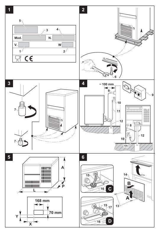
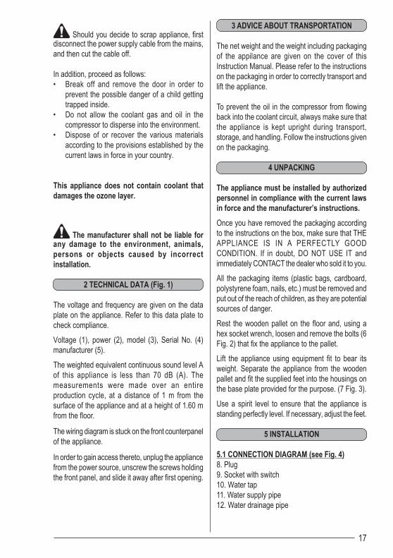
2 TECHNICAL DATA (Fig. 1)
The voltage and frequency are given on the dataplate on the appliance. Refer to this data plate tocheck compliance.
Voltage (1), power (2), model (3), Serial No. (4)manufacturer (5).
The weighted equivalent continuous sound level Aof this appliance is less than 70 dB (A). Themeasurements were made over an entireproduction cycle, at a distance of 1 m from thesurface of the appliance and at a height of 1.60 mfrom the floor.
The wiring diagram is stuck on the front counterpanelof the appliance.
In order to gain access thereto, unplug the appliancefrom the power source, unscrew the screws holdingthe front panel, and slide it away after first opening.
3 ADVICE ABOUT TRANSPORTATION
The net weight and the weight including packagingof the appilance are given on the cover of thisInstruction Manual. Please refer to the instructionson the packaging in order to correctly transport andlift the appliance.
To prevent the oil in the compressor from flowingback into the coolant circuit, always make sure thatthe appliance is kept upright during transport,storage, and handling. Follow the instructions givenon the packaging.
4 UNPACKING
The appliance must be installed by authorizedpersonnel in compliance with the current lawsin force and the manufacturer’s instructions.
Once you have removed the packaging accordingto the instructions on the box, make sure that THEAPPLIANCE IS IN A PERFECTLY GOODCONDITION. If in doubt, DO NOT USE IT andimmediately CONTACT the dealer who sold it to you.
All the packaging items (plastic bags, cardboard,polystyrene foam, nails, etc.) must be removed andput out of the reach of children, as they are potentialsources of danger.
Rest the wooden pallet on the floor and, using ahex socket wrench, loosen and remove the bolts (6Fig. 2) that fix the appliance to the pallet.
Lift the appliance using equipment fit to bear itsweight. Separate the appliance from the woodenpallet and fit the supplied feet into the housings onthe base plate provided for the purpose. (7 Fig. 3).
Use a spirit level to ensure that the appliance isstanding perfectly level. If necessary, adjust the feet.
5 INSTALLATION
5.1 CONNECTION DIAGRAM (see Fig. 4)8. Plug9. Socket with switch10. Water tap11. Water supply pipe12. Water drainage pipe
18
5.2 POSITIONINGIt is advisable to install the appliance in a roomwhere the temperature is between 10°C and35°C, and with a water supply temperature ofbetween 3°C and 25°C.Avoid installing the appliance where it may beexposed to direct sunlight or near heat sourcessuch as radiators, stoves, dishwashers, etc.
This appliance• must not be used outdoors• must not the installed in damp places or where
it is liable to be sprayed with water• must be positioned at a distance of at least 5
cm from the side walls (this does not apply tobuilt-in models).
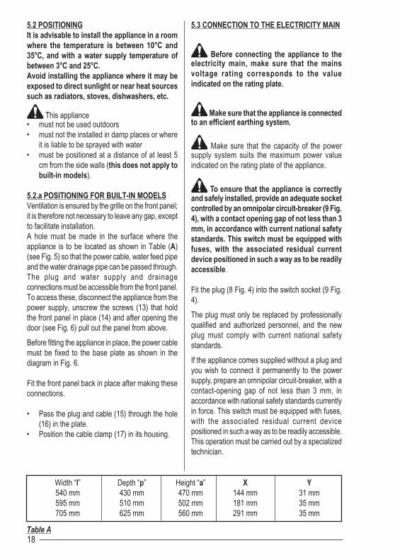
5.2.a POSITIONING FOR BUILT-IN MODELSVentilation is ensured by the grille on the front panel;it is therefore not necessary to leave any gap, exceptto facilitate installation.A hole must be made in the surface where theappliance is to be located as shown in Table (A)(see Fig. 5) so that the power cable, water feed pipeand the water drainage pipe can be passed through.The plug and water supply and drainageconnections must be accessible from the front panel.To access these, disconnect the appliance from thepower supply, unscrew the screws (13) that holdthe front panel in place (14) and after opening thedoor (see Fig. 6) pull out the panel from above.
Before fitting the appliance in place, the power cablemust be fixed to the base plate as shown in thediagram in Fig. 6.
Fit the front panel back in place after making theseconnections.
• Pass the plug and cable (15) through the hole(16) in the plate.
• Position the cable clamp (17) in its housing.
5.3 CONNECTION TO THE ELECTRICITY MAIN
Before connecting the appliance to theelectricity main, make sure that the mainsvoltage rating corresponds to the valueindicated on the rating plate.
Make sure that the appliance is connectedto an efficient earthing system.
Make sure that the capacity of the powersupply system suits the maximum power valueindicated on the rating plate of the appliance.
To ensure that the appliance is correctlyand safely installed, provide an adequate socketcontrolled by an omnipolar circuit-breaker (9 Fig.4), with a contact opening gap of not less than 3mm, in accordance with current national safetystandards. This switch must be equipped withfuses, with the associated residual currentdevice positioned in such a way as to be readilyaccessible.
Fit the plug (8 Fig. 4) into the switch socket (9 Fig.4).
The plug must only be replaced by professionallyqualified and authorized personnel, and the newplug must comply with current national safetystandards.
If the appliance comes supplied without a plug andyou wish to connect it permanently to the powersupply, prepare an omnipolar circuit-breaker, with acontact-opening gap of not less than 3 mm, inaccordance with national safety standards currentlyin force. This switch must be equipped with fuses,with the associated residual current devicepositioned in such a way as to be readily accessible.This operation must be carried out by a specializedtechnician.
Table A
Width “l” Depth “p” Height “a” X Y540 mm 430 mm 470 mm 144 mm 31 mm595 mm 510 mm 502 mm 181 mm 35 mm705 mm 625 mm 560 mm 291 mm 35 mm
19
Make sure that you fully uncoil the powersupply cable and check that it is not crushed inany way.
Should the supply cable be damaged, itmust be replaced by a specialized technicianusing a special cable available from themanufacturer or from the Technical ServiceCenters.
5.4 CONNECTION TO THE WATER MAIN
This appliance must be only be suppliedwith cold water for human consumption(drinking water).
The operating pressure must be between 0.1 and0.6 MPa.
The appliance must be connected to the water mainby professionally qualified personnel in accordancewith the manufacturer’s instructions.
A tap must be installed between the watermains and the feed pipe of the appliance, so thatthe water supply may be shut off if necessary.
Where the feed water is particularly hard, you areadvised to install a softener. Any solid particles (e.g.sand) may be eliminated by installing a mechanicalfilter, which must be periodically inspected andcleaned. These devices must comply with thestandards in force in the country of use.
Never turn the water supply tap off whenthe appliance is working.
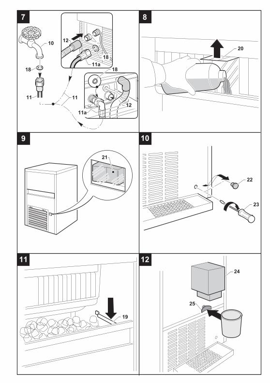
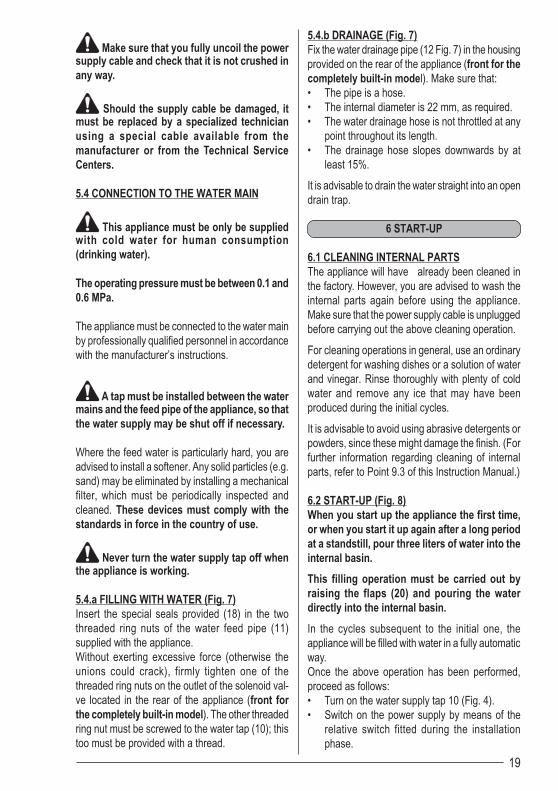
5.4.a FILLING WITH WATER (Fig. 7)Insert the special seals provided (18) in the twothreaded ring nuts of the water feed pipe (11)supplied with the appliance.Without exerting excessive force (otherwise theunions could crack), firmly tighten one of thethreaded ring nuts on the outlet of the solenoid val-ve located in the rear of the appliance (front forthe completely built-in model). The other threadedring nut must be screwed to the water tap (10); thistoo must be provided with a thread.
5.4.b DRAINAGE (Fig. 7)Fix the water drainage pipe (12 Fig. 7) in the housingprovided on the rear of the appliance (front for thecompletely built-in model). Make sure that:• The pipe is a hose.• The internal diameter is 22 mm, as required.• The water drainage hose is not throttled at any
point throughout its length.• The drainage hose slopes downwards by at
least 15%.
It is advisable to drain the water straight into an opendrain trap.
6 START-UP
6.1 CLEANING INTERNAL PARTSThe appliance will have already been cleaned inthe factory. However, you are advised to wash theinternal parts again before using the appliance.Make sure that the power supply cable is unpluggedbefore carrying out the above cleaning operation.
For cleaning operations in general, use an ordinarydetergent for washing dishes or a solution of waterand vinegar. Rinse thoroughly with plenty of coldwater and remove any ice that may have beenproduced during the initial cycles.
It is advisable to avoid using abrasive detergents orpowders, since these might damage the finish. (Forfurther information regarding cleaning of internalparts, refer to Point 9.3 of this Instruction Manual.)
6.2 START-UP (Fig. 8)When you start up the appliance the first time,or when you start it up again after a long periodat a standstill, pour three liters of water into theinternal basin.
This filling operation must be carried out byraising the flaps (20) and pouring the waterdirectly into the internal basin.
In the cycles subsequent to the initial one, theappliance will be filled with water in a fully automaticway.Once the above operation has been performed,proceed as follows:• Turn on the water supply tap 10 (Fig. 4).• Switch on the power supply by means of the
relative switch fitted during the installationphase.
20
For appliances that are connected permanently tothe electricity main, turn on by means of the switchon the outside of the appliance, fitted during theinstallation phase.
Start by pressing the relative switch (21 Fig. 9) whichwill light up if provided with this function.
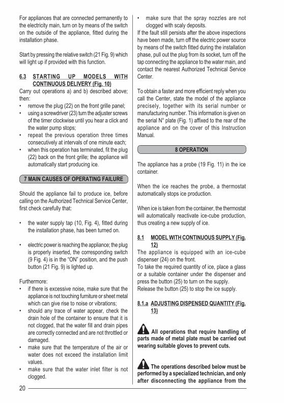
6.3 STARTING UP MODELS WITHCONTINUOUS DELIVERY (Fig. 10)
Carry out operations a) and b) described above;then:• remove the plug (22) on the front grille panel;• using a screwdriver (23) turn the adjuster screws
of the timer clockwise until you hear a click andthe water pump stops;
• repeat the previous operation three timesconsecutively at intervals of one minute each;
• when this operation has terminated, fit the plug(22) back on the front grille; the appliance willautomatically start producing ice.
7 MAIN CAUSES OF OPERATING FAILURE
Should the appliance fail to produce ice, beforecalling on the Authorized Technical Service Center,first check carefully that:
• the water supply tap (10, Fig. 4), fitted duringthe installation phase, has been turned on.
• electric power is reaching the appliance; the plugis properly inserted, the corresponding switch(9 Fig. 4) is in the “ON” position, and the pushbutton (21 Fig. 9) is lighted up.
Furthermore:• if there is excessive noise, make sure that the
appliance is not touching furniture or sheet metalwhich can give rise to noise or vibrations;
• should any trace of water appear, check thedrain hole of the container to ensure that it isnot clogged, that the water fill and drain pipesare correctly connected and are not throttled ordamaged.
• make sure that the temperature of the air orwater does not exceed the installation limitvalues.
• make sure that the water inlet filter is notclogged.
• make sure that the spray nozzles are notclogged with scaly deposits.
If the fault still persists after the above inspectionshave been made, turn off the electric power sourceby means of the switch fitted during the installationphase, pull out the plug from its socket, turn off thetap connecting the appliance to the water main, andcontact the nearest Authorized Technical ServiceCenter.
To obtain a faster and more efficient reply when youcall the Center, state the model of the applianceprecisely, together with its serial number ormanufacturing number. This information is given onthe serial N° plate (Fig. 1) affixed to the rear of theappliance and on the cover of this InstructionManual.
8 OPERATION
The appliance has a probe (19 Fig. 11) in the icecontainer.
When the ice reaches the probe, a thermostatautomatically stops ice production.
When ice is taken from the container, the thermostatwill automatically reactivate ice-cube production,thus creating a new supply of ice.
8.1 MODEL WITH CONTINUOUS SUPPLY (Fig.12)
The appliance is equipped with an ice-cubedispenser (24) on the front.To take the required quantity of ice, place a glassor a suitable container under the dispenser andpress the button (25) to turn on the supply.Release the button (25) to stop the ice supply.
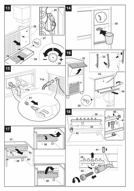
8.1.a ADJUSTING DISPENSED QUANTITY (Fig.13)
All operations that require handling ofparts made of metal plate must be carried outwearing suitable gloves to prevent cuts.
The operations described below must beperformed by a specialized technician, and onlyafter disconnecting the appliance from the
21
electricity main.The appliance is provided with an electronic devicefor adjusting the quantity of ice dispensed each time.To increase or decrease the dispensing time andthe proportionate quantity of ice dispensed, proceedas follows:• remove the basin (26)• slacken off the screws (27) on the front panel
(28) using a crossheaded screwdriver• pull out the front panel (28) from above• turn the knob (29) on the electronic device
clockwise to increase the quantity of icedispensed whenever the button is pressed, andanti-clockwise to reduce the quantity.
8.2 MODEL WITH COLD WATER DISPENSER(Fig. 14)
The appliance is provided with a cold waterdispenser located beside the ice container.To obtain cold water, place a glass under the outletand gently press the button (30) to turn on the watertap.Release the button to stop the flow of cold water.If the appliance is already provided with a filterlocated on the cold water supply circuit, read theinstructions on the filter label carefully and followthe manufacturer’s recommendations regarding thereplacement schedules.
9 MAINTENANCE
9.1 CLEANING THE SOLENOID VALVE FILTER
At least every two months, clean the filter (31Fig. 15) located on the water inlet solenoid valve,proceeding as follows:• Switch off the electric power supply by means
of the switch (9 Fig. 4), fitted during installation,and disconnect the plug of the appliance fromits socket.
• Shut off the water supply by turning the tap (10Fig. 7) fitted during installation.
• Unscrew the threaded ring nut (11a Fig. 15) ofthe water feed hose, located at the outlet of thesolenoid valve at the rear of the appliance (frontfor the built-in model). For the built-in model,first remove the panel as indicated at point 5.2.a.
• Using a pair of pliers, remove the filter (31 Fig.15) from its seat without damaging the waterfeed pipe connector.
• Place the filter under a strong jet of water to
remove residue, but replace the filter if it isexcessively dirty.
After having carried out the cleaning operations, refitthe filter and hose pipe taking the necessaryprecautions described earlier in the InstructionManual.
When the operations have terminated, turn onboth the electricity supply and water supply.
9.2 AIR-COOLED MODELSFor air-cooled models, it is very important to keepthe finned condenser clean.
Have the finned condenser cleaned at least onceevery two months by an authorized TechnicalService Center, which can include this operation inthe scheduled maintenance program.
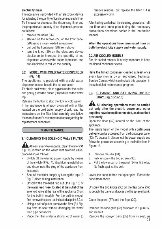
9.3 CLEANING AND SANITIZING THE ICETRAY (Fig. 16-17-18)
All cleaning operations must be carriedout only after the electric power and watersupplies have been disconnected, as describedpreviously.Open the door (32) located on the front of theappliance.The inside basin of the model with continuousdelivery can be accessed from the front upper panel(33). To access it, disconnect the power supply andfollow the procedure according to the indications inFigure 16.
a. Remove the seal (34).b. Fully unscrew the two screws (35).c. Pull the lower part of the panel (34) until the tab
fits flush against the cell.
Lower the panel to free the upper pins. Extract thepanel from above.
Unscrew the two knobs (36) on the flap panel (37)to detach the panel and access to the sprayer bank.
Clean the panel (37) and the flaps (20).
Remove the slide grille (38) as shown in Figure 17,and clean it.Remove the sprayer bank (39) from its seat, as
22
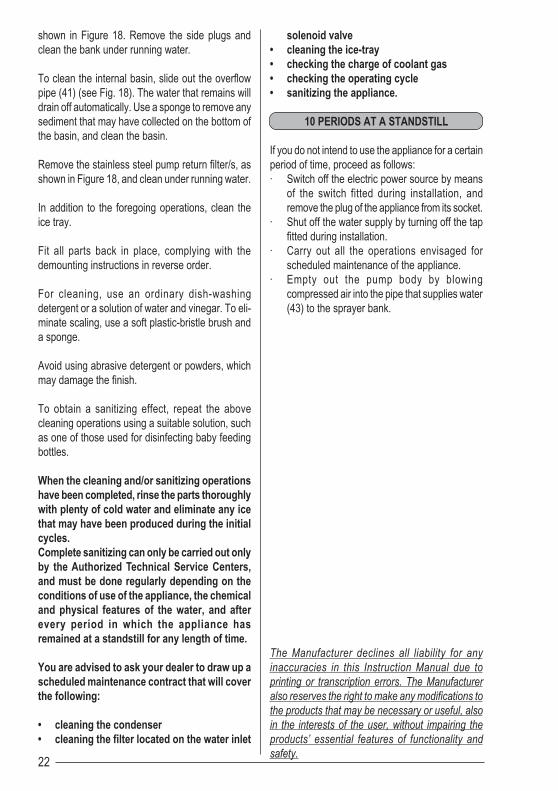
shown in Figure 18. Remove the side plugs andclean the bank under running water.
To clean the internal basin, slide out the overflowpipe (41) (see Fig. 18). The water that remains willdrain off automatically. Use a sponge to remove anysediment that may have collected on the bottom ofthe basin, and clean the basin.
Remove the stainless steel pump return filter/s, asshown in Figure 18, and clean under running water.
In addition to the foregoing operations, clean theice tray.
Fit all parts back in place, complying with thedemounting instructions in reverse order.
For cleaning, use an ordinary dish-washingdetergent or a solution of water and vinegar. To eli-minate scaling, use a soft plastic-bristle brush anda sponge.
Avoid using abrasive detergent or powders, whichmay damage the finish.
To obtain a sanitizing effect, repeat the abovecleaning operations using a suitable solution, suchas one of those used for disinfecting baby feedingbottles.
When the cleaning and/or sanitizing operationshave been completed, rinse the parts thoroughlywith plenty of cold water and eliminate any icethat may have been produced during the initialcycles.Complete sanitizing can only be carried out onlyby the Authorized Technical Service Centers,and must be done regularly depending on theconditions of use of the appliance, the chemicaland physical features of the water, and afterevery period in which the appliance hasremained at a standstill for any length of time.
You are advised to ask your dealer to draw up ascheduled maintenance contract that will coverthe following:
• cleaning the condenser• cleaning the filter located on the water inlet
solenoid valve• cleaning the ice-tray• checking the charge of coolant gas• checking the operating cycle• sanitizing the appliance.
10 PERIODS AT A STANDSTILL
If you do not intend to use the appliance for a certainperiod of time, proceed as follows:· Switch off the electric power source by means
of the switch fitted during installation, andremove the plug of the appliance from its socket.
· Shut off the water supply by turning off the tapfitted during installation.
· Carry out all the operations envisaged forscheduled maintenance of the appliance.
· Empty out the pump body by blowingcompressed air into the pipe that supplies water(43) to the sprayer bank.
The Manufacturer declines all liability for anyinaccuracies in this Instruction Manual due toprinting or transcription errors. The Manufactureralso reserves the right to make any modifications tothe products that may be necessary or useful, alsoin the interests of the user, without impairing theproducts’ essential features of functionality andsafety.

E’ vietata la riproduzione, anche solo parziale, del presente manuale di istruzioni.
It is strictly forbidden to reproduce this instruction manual or any part thereof.
La reproduction, y compris partielle, de ce manuel d’instructions, est interdite.
Eine vollständige oder auszugsweise Reproduktion des vorliegenden Handbuches ist verboten.
E prohibida la reproducción, an parcialmente, del presente manual de instrucciones.
Proíbe-se reproduzir, também parcialmente, o presente Manual de Instruções.
De Reproductie van dit Handboek met Instructies, ook alleen gedeeltelijk, is verboden.
Hel eller delvis kopiering eller genoptryk af denne vejledning er forbudt.
A·ÁoÚ‡ÂÙ·È Ë ·vÁÚ·Ê‹, ¤ÛÙˆ Î·È ÌÂÚÈ΋, Ùo˘ ·ÚfivÙo˜.
Alla rättigheter är reserverade. Kopiering eller reproduktion av denna manual är förbjuden.
Kaikki oikeudet pidätetään. Osittainenkin kopiointi kielletty.
Alle rettigheter reservert. Kopiering og reproduksjon forbudt.
CO
D. 2
4478
- 0
1R00