Embed Size (px)
Citation preview
MODAF-M10-004
MINISTRY OF DEFENCE
MOD Architectural Framework
Acquisition Community of Interest Deskbook
Draft 0.4
6 July 2005
Prepared by:-
Approved by:-
THIS DOCUMENT IS THE PROPERTY OF HER BRITANNIC MAJESTY’S GOVERNMENT, and is issued for the information of such persons only as need to know its contents in the course of their official duties.
- 1 -
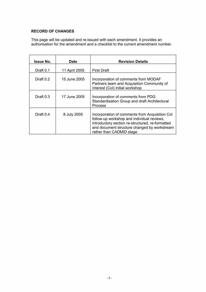
RECORD OF CHANGES
This page will be updated and re-issued with each amendment. It provides an authorisation for the amendment and a checklist to the current amendment number.
Issue No. Date Revision Details
Draft 0.1 11 April 2005 First Draft
Draft 0.2 15 June 2005 Incorporation of comments from MODAF Partners team and Acquisition Community of Interest (CoI) initial workshop
Draft 0.3 17 June 2005 Incorporation of comments from PDG Standardisation Group and draft Architectural Process
Draft 0.4 8 July 2005 Incorporation of comments from Acquisition CoI follow-up workshop and individual reviews, introductory section re-structured, re-formatted and document structure changed by workstream rather than CADMID stage
- 2 -
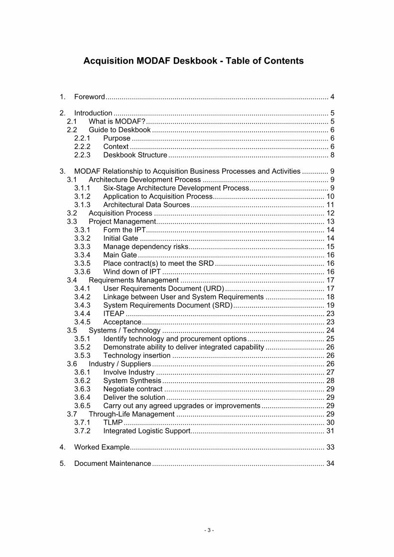
Acquisition MODAF Deskbook - Table of Contents
1. Foreword.............................................................................................................. 4
2. Introduction .......................................................................................................... 5 2.1 What is MODAF?.......................................................................................... 5 2.2 Guide to Deskbook ....................................................................................... 6
2.2.1 Purpose ................................................................................................. 6 2.2.2 Context .................................................................................................. 6 2.2.3 Deskbook Structure ............................................................................... 8
3. MODAF Relationship to Acquisition Business Processes and Activities ............. 9 3.1 Architecture Development Process .............................................................. 9
3.1.1 Six-Stage Architecture Development Process....................................... 9 3.1.2 Application to Acquisition Process....................................................... 10 3.1.3 Architectural Data Sources.................................................................. 11
3.2 Acquisition Process .................................................................................... 12 3.3 Project Management................................................................................... 13
3.3.1 Form the IPT........................................................................................ 14 3.3.2 Initial Gate ........................................................................................... 14 3.3.3 Manage dependency risks................................................................... 15 3.3.4 Main Gate ............................................................................................ 16 3.3.5 Place contract(s) to meet the SRD...................................................... 16 3.3.6 Wind down of IPT ................................................................................ 16
3.4 Requirements Management ....................................................................... 17 3.4.1 User Requirements Document (URD) ................................................. 17 3.4.2 Linkage between User and System Requirements ............................. 18 3.4.3 System Requirements Document (SRD)............................................. 19 3.4.4 ITEAP .................................................................................................. 23 3.4.5 Acceptance.......................................................................................... 23
3.5 Systems / Technology ................................................................................ 24 3.5.1 Identify technology and procurement options...................................... 25 3.5.2 Demonstrate ability to deliver integrated capability ............................. 26 3.5.3 Technology insertion ........................................................................... 26
3.6 Industry / Suppliers ..................................................................................... 26 3.6.1 Involve Industry ................................................................................... 27 3.6.2 System Synthesis ................................................................................ 28 3.6.3 Negotiate contract ............................................................................... 29 3.6.4 Deliver the solution .............................................................................. 29 3.6.5 Carry out any agreed upgrades or improvements ............................... 29
3.7 Through-Life Management ......................................................................... 29 3.7.1 TLMP................................................................................................... 30 3.7.2 Integrated Logistic Support.................................................................. 31
4. Worked Example................................................................................................ 33
5. Document Maintenance..................................................................................... 34
- 3 -
1. Foreword
(Generic foreword - championing the use of MODAF, covering mandation issues and policy, emphasis of the benefits of MODAF and an architectural approach – to be written by MOD)
- 4 -
2. Introduction
2.1 What is MODAF?
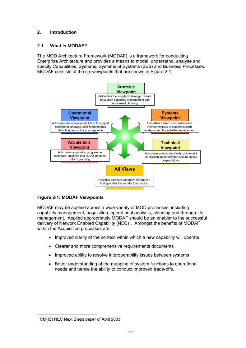
The MOD Architecture Framework (MODAF) is a framework for conducting Enterprise Architecture and provides a means to model, understand, analyse and specify Capabilities, Systems, Systems of Systems (SoS) and Business Processes. MODAF consists of the six viewpoints that are shown in Figure 2-1.
SystemsViewpoint
Articulates system composition and interconnectivity to support system
analysis, and through-life management
Acquisition Viewpoint
Articulates acquisition programme construct, timelines and DLOD status to
inform planning
All Views
Provides pertinent summary information that specifies the architecture product
Strategic Viewpoint
Articulates the long-term strategic picture to support capability management and
equipment planning
TechnicalViewpoint
Articulates policy, standards, guidance & constraints to specify and assure quality
expectations
Operational Viewpoint
Articulates the operational picture to support operational analysis, user requirements
definition, and solution acceptance
Figure 2-1: MODAF Viewpoints
MODAF may be applied across a wide variety of MOD processes, including capability management, acquisition, operational analysis, planning and through-life management. Applied appropriately MODAF should be an enabler to the successful delivery of Network Enabled Capability (NEC)1. Amongst the benefits of MODAF within the Acquisition processes are:
• Improved clarity of the context within which a new capability will operate
• Clearer and more comprehensive requirements documents
• Improved ability to resolve interoperability issues between systems
• Better understanding of the mapping of system functions to operational needs and hence the ability to conduct improved trade-offs.
- 5 -
1 CM(IS) NEC Next Steps paper of April 2003
2.2 Guide to Deskbook
2.2.1 Purpose
The purpose of this document is to explain to the Acquisition community how to produce MODAF compliant architectures and how the views within these architectures will support the various elements of the Acquisition lifecycle and processes.
2.2.2 Context
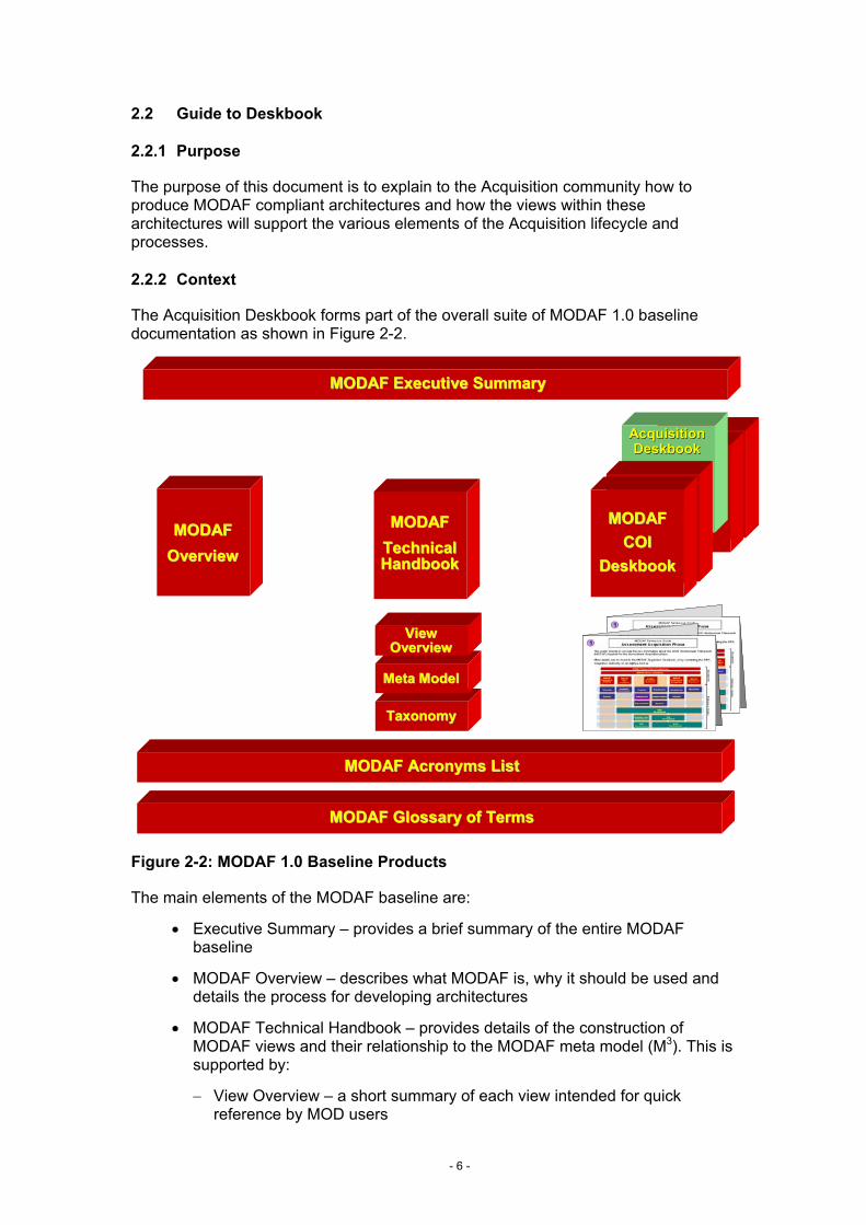
The Acquisition Deskbook forms part of the overall suite of MODAF 1.0 baseline documentation as shown in Figure 2-2.
TaxonomyTaxonomy
Meta ModelMeta Model
MODAF Acronyms ListMODAF Acronyms List
COI COI DeskboDeskbo
okok
COI COI DeskboDeskbo
okok
AcquisitionAcquisitionDeskbookDeskbook
COI COI DeskboDeskbo
okok
COI COI DeskboDeskbo
okok
MODAFMODAFCOICOI
DeskbookDeskbook
MODAFMODAFTechnical Technical HandbookHandbook
MODAFMODAFOverviewOverview
MODAF Executive SummaryMODAF Executive Summary
ViewViewOverviewOverview
ViewViewOverviewOverview
MODAF Glossary of TermsMODAF Glossary of Terms
Figure 2-2: MODAF 1.0 Baseline Products
The main elements of the MODAF baseline are:
• Executive Summary – provides a brief summary of the entire MODAF baseline
• MODAF Overview – describes what MODAF is, why it should be used and details the process for developing architectures
• MODAF Technical Handbook – provides details of the construction of MODAF views and their relationship to the MODAF meta model (M3). This is supported by:
− View Overview – a short summary of each view intended for quick reference by MOD users
- 6 -
− Meta Model – used to define the architectural objects that are permitted in MODAF views and their relationships with each other
− Taxonomy – provides the approved names and definitions for architectural objects to be used within the MOD’s architectures
• MODAF Deskbooks – describe how users within particular communities in the MOD are expected to utilise MODAF architectures to support their processes. Each of the Deskbooks has one or more “quick start guides” that provide an easy reference summary of the relationship of MODAF views to the community’s processes
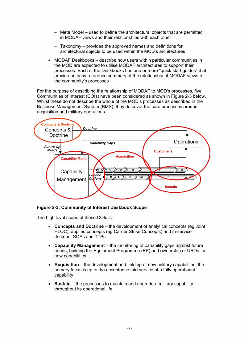
For the purpose of describing the relationship of MODAF to MOD’s processes, five Communities of Interest (COIs) have been considered as shown in Figure 2-3 below. Whilst these do not describe the whole of the MOD’s processes as described in the Business Management System (BMS), they do cover the core processes around acquisition and military operations.
C A D M
C A D M I T
DI
Concepts & Doctrine
CapabilityManagement
Operations
FundedOptions
Capability GapsFuture Op
Needs
DoctrineConcepts & Doctrine
Capability Mgmt Acquisition
Sustain
Customer 2
Figure 2-3: Community of Interest Deskbook Scope
The high level scope of these COIs is:
• Concepts and Doctrine – the development of analytical concepts (eg Joint HLOC), applied concepts (eg Carrier Strike Concepts) and in-service doctrine, SOPs and TTPs
• Capability Management – the monitoring of capability gaps against future needs, building the Equipment Programme (EP) and ownership of URDs for new capabilities
• Acquisition – the development and fielding of new military capabilities, the primary focus is up to the acceptance into service of a fully operational capability
• Sustain – the processes to maintain and upgrade a military capability throughout its operational life
- 7 -
• Customer 2 – the Front Line Commands planning and conducting their operational activities including their Core Leadership and Pivotal Management roles as defined in Smart Acqusition2
2.2.3 Deskbook Structure
The remainder of the MODAF Acquisition Deskbook comprises two key sections:
Section 3 - MODAF’s Relationship to the Acquisition Processes and Activities – this section explains the process of architecting as applied by those engaged in the acquisition process. Specifically, it identifies the key business processes and activities of the CADMID cycle and suggests how these align with the MODAF Viewpoints.
Section 4 - Worked Example of MODAF in Acquisition – this section demonstrates how MODAF can be used practically within CADMID by means of a real-life architecture example.
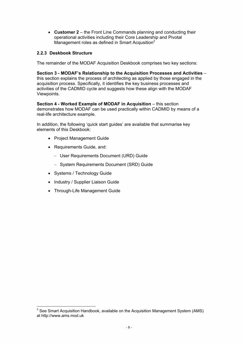
In addition, the following ‘quick start guides’ are available that summarise key elements of this Deskbook:
• Project Management Guide
• Requirements Guide, and:
− User Requirements Document (URD) Guide
− System Requirements Document (SRD) Guide
• Systems / Technology Guide
• Industry / Supplier Liaison Guide
• Through-Life Management Guide
2 See Smart Acquisition Handbook, available on the Acquisition Management System (AMS) at http://www.ams.mod.uk
- 8 -
3. MODAF Relationship to Acquisition Business Processes and Activities
3.1 Architecture Development Process
3.1.1 Six-Stage Architecture Development Process
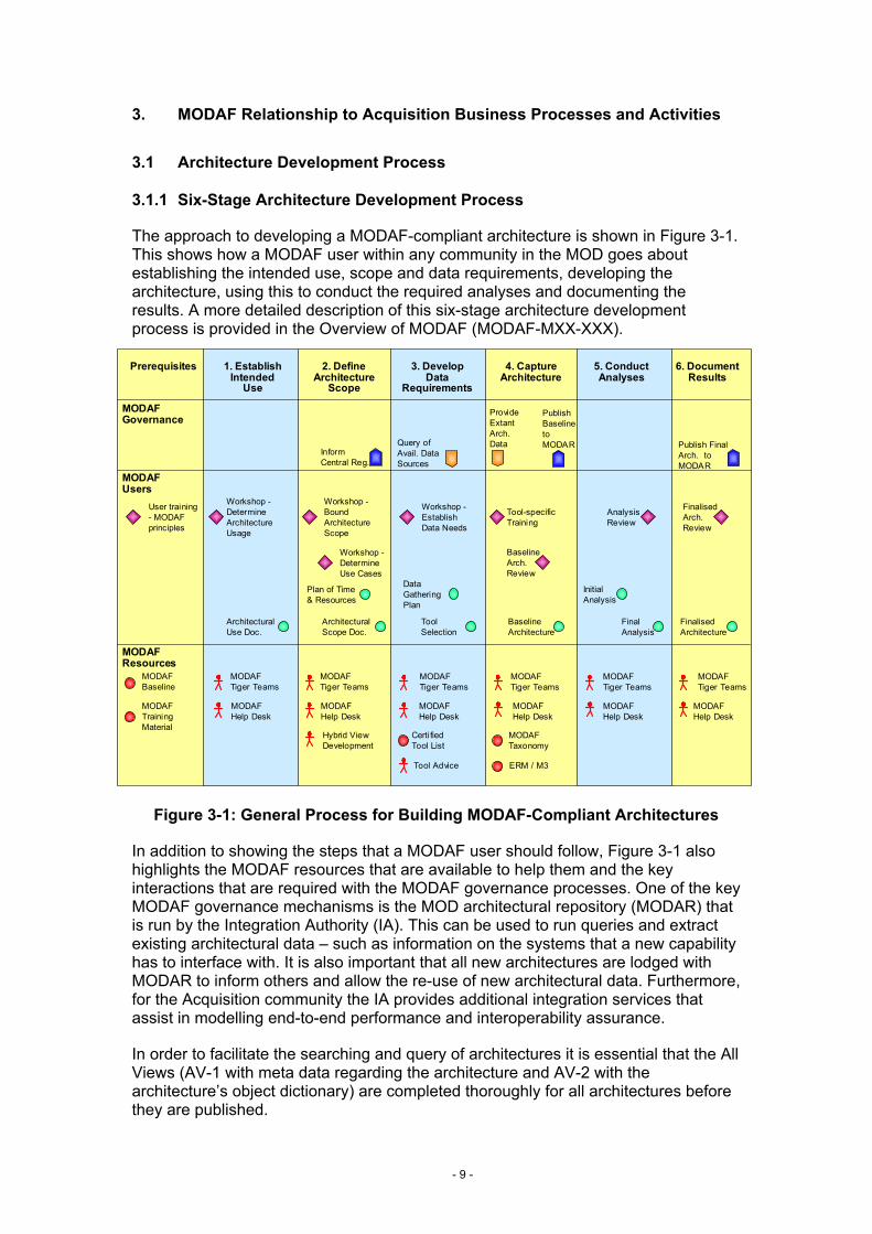
The approach to developing a MODAF-compliant architecture is shown in Figure 3-1. This shows how a MODAF user within any community in the MOD goes about establishing the intended use, scope and data requirements, developing the architecture, using this to conduct the required analyses and documenting the results. A more detailed description of this six-stage architecture development process is provided in the Overview of MODAF (MODAF-MXX-XXX).
User training- MODAF principles
Prerequisites 1. Establish Intended
Use
2. Define Architecture
Scope
3. Develop Data
Requirements
4. Capture Architecture
5. Conduct Analyses
6. Document Results
MODAF Governance
MODAF Users
MODAF Resources
MODAF Baseline
Architectural Use Doc.
Workshop -Determine Architecture Usage
Workshop -Bound Architecture Scope
Workshop -Establish Data Needs
Architectural Scope Doc.
Tool Selection
Data Gathering Plan
BaselineArch. Review
Baseline Architecture
Inform Central Reg.
Query of Avail. Data Sources
Publish Baseline to MODAR
Tool-specific Training
Initial Analysis
Final Analysis
Analysis Review
Finalised Architecture
Finalised Arch. Review
Publish Final Arch. to MODAR
Provide Extant Arch.Data
MODAF Training Material
MODAF Tiger Teams
MODAF Tiger Teams
MODAF Help Desk
MODAF Help Desk
MODAF Help Desk
MODAF Help Desk
MODAF Help Desk
MODAF Help Desk
MODAF Tiger Teams
Certified Tool List
Tool Advice
Hybrid View Development
MODAF Tiger Teams
MODAF Tiger Teams
MODAF Tiger Teams
MODAF Taxonomy
ERM / M3
Workshop -Determine Use Cases
Plan of Time & Resources
Figure 3-1: General Process for Building MODAF-Compliant Architectures
In addition to showing the steps that a MODAF user should follow, Figure 3-1 also highlights the MODAF resources that are available to help them and the key interactions that are required with the MODAF governance processes. One of the key MODAF governance mechanisms is the MOD architectural repository (MODAR) that is run by the Integration Authority (IA). This can be used to run queries and extract existing architectural data – such as information on the systems that a new capability has to interface with. It is also important that all new architectures are lodged with MODAR to inform others and allow the re-use of new architectural data. Furthermore, for the Acquisition community the IA provides additional integration services that assist in modelling end-to-end performance and interoperability assurance.
In order to facilitate the searching and query of architectures it is essential that the All Views (AV-1 with meta data regarding the architecture and AV-2 with the architecture’s object dictionary) are completed thoroughly for all architectures before they are published.
- 9 -
3.1.2 Application to Acquisition Process
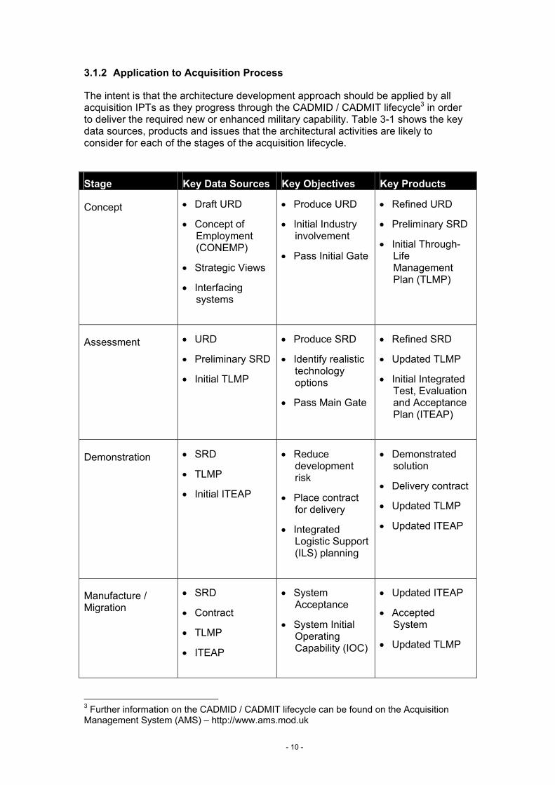
The intent is that the architecture development approach should be applied by all acquisition IPTs as they progress through the CADMID / CADMIT lifecycle3 in order to deliver the required new or enhanced military capability. Table 3-1 shows the key data sources, products and issues that the architectural activities are likely to consider for each of the stages of the acquisition lifecycle.
Stage Key Data Sources Key Objectives Key Products
Concept • Draft URD
• Concept of Employment (CONEMP)
• Strategic Views
• Interfacing systems
• Produce URD
• Initial Industry involvement
• Pass Initial Gate
• Refined URD
• Preliminary SRD
• Initial Through-Life Management Plan (TLMP)
Assessment • URD
• Preliminary SRD
• Initial TLMP
• Produce SRD
• Identify realistic technology options
• Pass Main Gate
• Refined SRD
• Updated TLMP
• Initial Integrated Test, Evaluation and Acceptance Plan (ITEAP)
Demonstration • SRD
• TLMP
• Initial ITEAP
• Reduce development risk
• Place contract for delivery
• Integrated Logistic Support (ILS) planning
• Demonstrated solution
• Delivery contract
• Updated TLMP
• Updated ITEAP
Manufacture / Migration
• SRD
• Contract
• TLMP
• ITEAP
• System Acceptance
• System Initial Operating Capability (IOC)
• Updated ITEAP
• Accepted System
• Updated TLMP
3 Further information on the CADMID / CADMIT lifecycle can be found on the Acquisition Management System (AMS) – http://www.ams.mod.uk
- 10 -
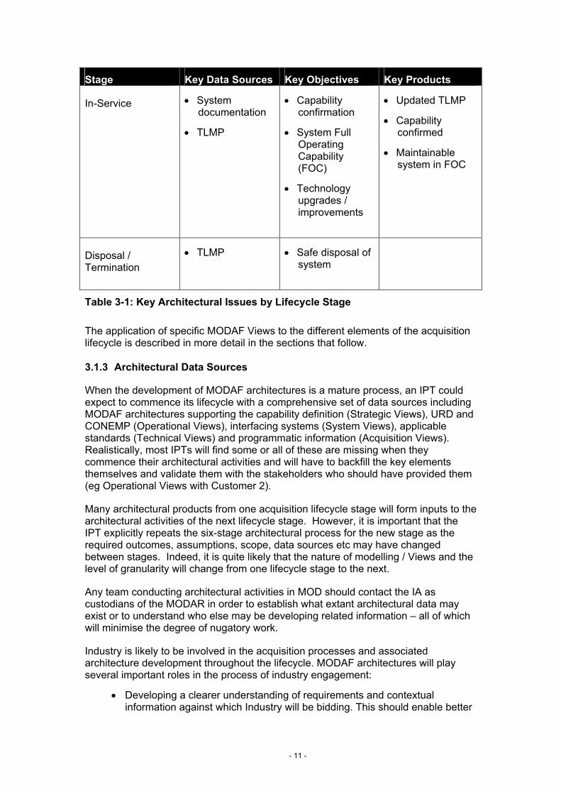
Stage Key Data Sources Key Objectives Key Products
In-Service • System documentation
• TLMP
• Capability confirmation
• System Full Operating Capability (FOC)
• Technology upgrades / improvements
• Updated TLMP
• Capability confirmed
• Maintainable system in FOC
Disposal / Termination
• TLMP • Safe disposal of system
Table 3-1: Key Architectural Issues by Lifecycle Stage
The application of specific MODAF Views to the different elements of the acquisition lifecycle is described in more detail in the sections that follow.
3.1.3 Architectural Data Sources
When the development of MODAF architectures is a mature process, an IPT could expect to commence its lifecycle with a comprehensive set of data sources including MODAF architectures supporting the capability definition (Strategic Views), URD and CONEMP (Operational Views), interfacing systems (System Views), applicable standards (Technical Views) and programmatic information (Acquisition Views). Realistically, most IPTs will find some or all of these are missing when they commence their architectural activities and will have to backfill the key elements themselves and validate them with the stakeholders who should have provided them (eg Operational Views with Customer 2).
Many architectural products from one acquisition lifecycle stage will form inputs to the architectural activities of the next lifecycle stage. However, it is important that the IPT explicitly repeats the six-stage architectural process for the new stage as the required outcomes, assumptions, scope, data sources etc may have changed between stages. Indeed, it is quite likely that the nature of modelling / Views and the level of granularity will change from one lifecycle stage to the next.
Any team conducting architectural activities in MOD should contact the IA as custodians of the MODAR in order to establish what extant architectural data may exist or to understand who else may be developing related information – all of which will minimise the degree of nugatory work.
Industry is likely to be involved in the acquisition processes and associated architecture development throughout the lifecycle. MODAF architectures will play several important roles in the process of industry engagement:
• Developing a clearer understanding of requirements and contextual information against which Industry will be bidding. This should enable better
- 11 -
estimates to be obtained with lower risk content and hence improved project outcomes in terms of cost and schedule
• Providing a mechanism to document the design solution being provided by Industry so that others may more readily interface with or utilise it – improving interoperability
However, initially at least, it is not expected that Industry will provide documentation of more than its highest level designs in MODAF formats and it will wish to protect its proprietary information and technology. Therefore, it is expected that industry will provide “grey box models” of its solutions during the acquisition lifecycle. These models will be expected to provide comprehensive definition of the system interfaces / services, applicable standards and data formats but will not expose more than basic information regarding the internal system functions.
3.2 Acquisition Process
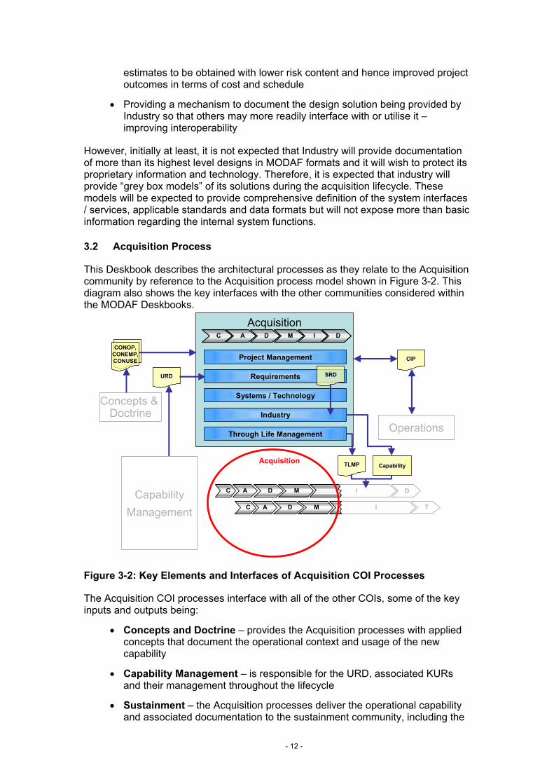
This Deskbook describes the architectural processes as they relate to the Acquisition community by reference to the Acquisition process model shown in Figure 3-2. This diagram also shows the key interfaces with the other communities considered within the MODAF Deskbooks.
Acquisition
I T
DI
Concepts & Doctrine
CapabilityManagement
Operations
C A D M
C A D M
CC
Project Management
Requirements
Systems / Technology
Industry
Through Life Management
AA DD MM II DD
URD SRD
CapabilityTLMP
CONOP,CONEMP,CONUSE CIP
Acquisition
Figure 3-2: Key Elements and Interfaces of Acquisition COI Processes
The Acquisition COI processes interface with all of the other COIs, some of the key inputs and outputs being:
• Concepts and Doctrine – provides the Acquisition processes with applied concepts that document the operational context and usage of the new capability
• Capability Management – is responsible for the URD, associated KURs and their management throughout the lifecycle
• Sustainment – the Acquisition processes deliver the operational capability and associated documentation to the sustainment community, including the
- 12 -
TLPM and MODAF architecture. In practice, the sustainment activities will normally be conducted by the same IPT as conducted the acquisition processes. There will be a progressive shift of focus as the capability moves from Manufacture into In-Service and the sustainment activities should be considered / planned for from the earliest stages of the CADMID cycle
• Customer 2 – the Capability Integration Plan (CIP) that defines responsibilities and integration mechanisms across all of the DLODs is developed in conjunction with Customer 2
The role of MODAF architectures in supporting the Acquisition COI processes and its key interfaces with the other COIs is described in the sections that follow, structured according to the main sub-processes shown in Figure 3-2.
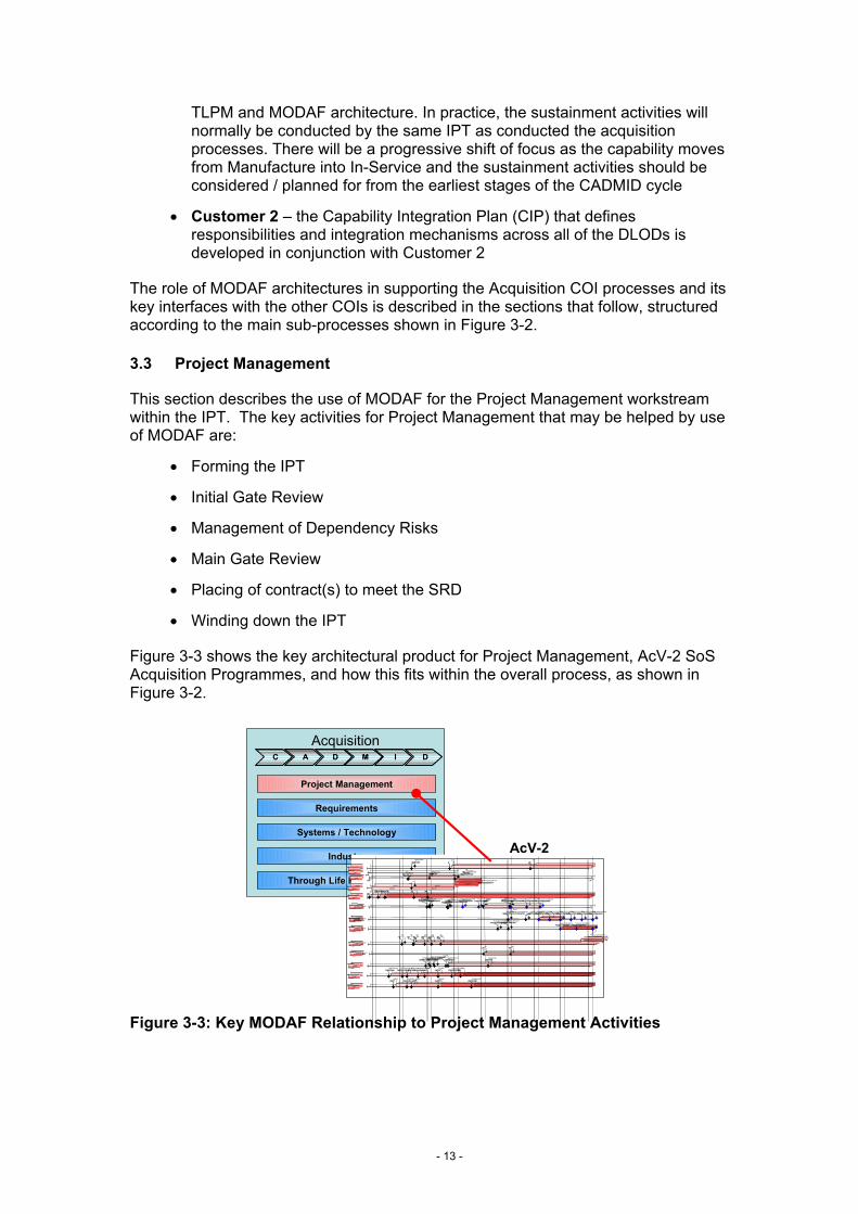
3.3 Project Management
This section describes the use of MODAF for the Project Management workstream within the IPT. The key activities for Project Management that may be helped by use of MODAF are:
• Forming the IPT
• Initial Gate Review
• Management of Dependency Risks
• Main Gate Review
• Placing of contract(s) to meet the SRD
• Winding down the IPT
Figure 3-3 shows the key architectural product for Project Management, AcV-2 SoS Acquisition Programmes, and how this fits within the overall process, as shown in Figure 3-2.
Figure 3-3: Key MODAF Relationship to Project Management Activities
Acquisition
Operations
CC
Project Management
Requirements
Systems / Technology
Industry
Through Life Management
AA DD MM II DD
,2& )2&
:DWFKNHHSHU
2FW 'HF51&66
%/'&66,)/3'5
)DOFRQ,QFUHPHQW$
0DLQ*DWH,QF$,QLWLDO*D WH,QF%,QF$'0&WW/H W
)LHOG7ULDOV'HOLYHU7UDQFKH 'HOLYHU7UDQFKH 'HOLYHU7UDQFKH,QF$,6'
,QF$,6'0DLQ*DWH,QF%
'HOLYHU7UDQFKH
'HOLYHU7UDQFKH'HOLYHU7UDQFKH
)DOFRQ,QFUHPHQW%
'0&WW/H W
)DOFRQ,QFUHPHQW&
,QLWLDO*D WH,QF&
)LHOG7ULDOV,QF%'HOLYHU7UDQFKH'HOLYHU7UDQFKH'HOLYHU7UDQFKH'HOLYHU7UDQFKH'HOLYHU7UDQFKH'HOLYHU7UDQFKH
'HOLYHU57768SJUDGH'HOLYHU7UDQFKH 'HOLYHU7UDQFKH
'HOLYHU7UDQFKH
7HFKQRORJ\UHIUHVKHV
&RUPRUDQW
0D\,6'
0D\)2&
2FW)2&
'HF,6'
0D\06$0
-DQ06$0
2FW 'HF0DU9HUVLRQ
'HF9HUVLRQ
0HUJHG&66-2&6"-2&6
&RPPRQ2SHUDWLRQDO&RPPDQG6XSSRU W6\VWHP"
6HS,QF%$VVHVV3KDVH&WW/H W
$6725
2S7ULDOVDF*6 2S7ULDOVDF*6 %$786WULDO,6'/LP&5
,2&)XOO&5&WWRULQWHJWULDOV
-&6/RJ
3KDVH,QF3KDVH,QF,2&
)2&)2&
',,
0DLQ*DWH ,6' )2&
%2:0$1
&,3
5$)&&,6
,6' /LWWRUDO25'$025'
(&,32)7 ,&,3WR',/ )&,3WR',/)&%,6$,2&
6WDJH 6WDJH
"
)XOO)&%,6$
/DQG25'%RZPDQ,2& %RZPDQ,6'&DSDELOLW\25'&DSDELOLW\%GH2)7
,2& )2&
:DWFKNHHSHU
2FW 'HF51&66
,2& )2&
:DWFKNHHSHU
2FW 'HF51&66
%/'&66,)/3'5
)DOFRQ,QFUHPHQW$
0DLQ*DWH,QF$,QLWLDO*D WH,QF%,QF$'0&WW/H W
)LHOG7ULDOV'HOLYHU7UDQFKH 'HOLYHU7UDQFKH 'HOLYHU7UDQFKH,QF$,6'
,QF$,6'0DLQ*DWH,QF%
'HOLYHU7UDQFKH
'HOLYHU7UDQFKH'HOLYHU7UDQFKH
%/'&66,)/3'5
)DOFRQ,QFUHPHQW$
0DLQ*DWH,QF$,QLWLDO*D WH,QF%,QF$'0&WW/H W
)LHOG7ULDOV'HOLYHU7UDQFKH 'HOLYHU7UDQFKH 'HOLYHU7UDQFKH,QF$,6'
,QF$,6'0DLQ*DWH,QF%
'HOLYHU7UDQFKH
'HOLYHU7UDQFKH'HOLYHU7UDQFKH
)DOFRQ,QFUHPHQW%
'0&WW/H W
)DOFRQ,QFUHPHQW&
,QLWLDO*D WH,QF&
)LHOG7ULDOV,QF%'HOLYHU7UDQFKH'HOLYHU7UDQFKH'HOLYHU7UDQFKH'HOLYHU7UDQFKH'HOLYHU7UDQFKH'HOLYHU7UDQFKH
'HOLYHU57768SJUDGH'HOLYHU7UDQFKH 'HOLYHU7UDQFKH
'HOLYHU7UDQFKH
)DOFRQ,QFUHPHQW%
'0&WW/H W
)DOFRQ,QFUHPHQW&
,QLWLDO*D WH,QF&
)LHOG7ULDOV,QF%'HOLYHU7UDQFKH'HOLYHU7UDQFKH'HOLYHU7UDQFKH'HOLYHU7UDQFKH'HOLYHU7UDQFKH'HOLYHU7UDQFKH
'HOLYHU57768SJUDGH'HOLYHU7UDQFKH 'HOLYHU7UDQFKH
'HOLYHU7UDQFKH
7HFKQRORJ\UHIUHVKHV
&RUPRUDQW
0D\,6'
0D\)2&
2FW)2&
'HF,6'
0D\06$0
-DQ06$0
2FW 'HF0DU9HUVLRQ
'HF9HUVLRQ
0HUJHG&66-2&6"-2&6
&RPPRQ2SHUDWLRQDO&RPPDQG6XSSRU W6\VWHP"
6HS,QF%$VVHVV3KDVH&WW/H W
7HFKQRORJ\UHIUHVKHV
&RUPRUDQW
0D\,6'
0D\)2&
2FW)2&
'HF,6'
0D\06$0
-DQ06$0
2FW 'HF0DU9HUVLRQ
'HF9HUVLRQ
0HUJHG&66-2&6"-2&6
&RPPRQ2SHUDWLRQDO&RPPDQG6XSSRU W6\VWHP"
6HS,QF%$VVHVV3KDVH&WW/H W
$6725
2S7ULDOVDF*6 2S7ULDOVDF*6 %$786WULDO,6'/LP&5
,2&)XOO&5&WWRULQWHJWULDOV
-&6/RJ
3KDVH,QF3KDVH,QF,2&
)2&
$6725
2S7ULDOVDF*6 2S7ULDOVDF*6 %$786WULDO,6'/LP&5
,2&)XOO&5&WWRULQWHJWULDOV
-&6/RJ
3KDVH,QF3KDVH,QF,2&
)2&)2&
',,
0DLQ*DWH ,6' )2&
%2:0$1
)2&
',,
0DLQ*DWH ,6' )2&
%2:0$1
&,3
5$)&&,6
,6' /LWWRUDO25'$025'
(&,32)7 ,&,3WR',/ )&,3WR',/)&%,6$,2&
6WDJH 6WDJH
"
)XOO)&%,6$
/DQG25'%RZPDQ,2& %RZPDQ,6'&DSDELOLW\25'&DSDELOLW\
&,3
5$)&&,6
,6' /LWWRUDO25'$025'
(&,32)7 ,&,3WR',/ )&,3WR',/)&%,6$,2&
6WDJH 6WDJH
"
)XOO)&%,6$
/DQG25'%RZPDQ,2& %RZPDQ,6'&DSDELOLW\25'&DSDELOLW\%GH2)7
AcV-2
- 13 -
3.3.1 Form the IPT
The IPT may be formed through the Future Business Group (FBG) where the project scope does not match that of an existing IPT. Alternatively, a new system may be allocated to an existing IPT if it fits with that IPT’s current programme of work.
Any existing MODAF Views and other supporting documentation should be made available to the IPT from the Customer 1 community, which has created and owned the Views developed up to and including the URD Views.
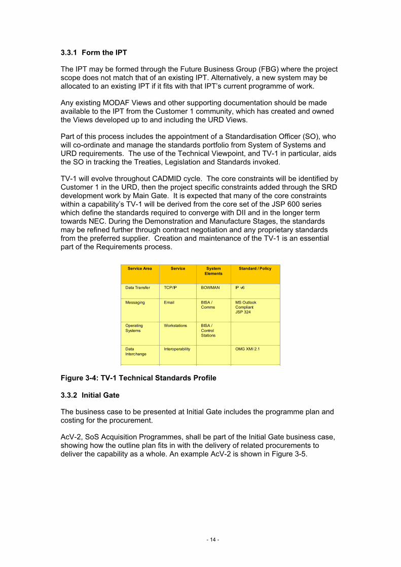
Part of this process includes the appointment of a Standardisation Officer (SO), who will co-ordinate and manage the standards portfolio from System of Systems and URD requirements. The use of the Technical Viewpoint, and TV-1 in particular, aids the SO in tracking the Treaties, Legislation and Standards invoked.
TV-1 will evolve throughout CADMID cycle. The core constraints will be identified by Customer 1 in the URD, then the project specific constraints added through the SRD development work by Main Gate. It is expected that many of the core constraints within a capability’s TV-1 will be derived from the core set of the JSP 600 series which define the standards required to converge with DII and in the longer term towards NEC. During the Demonstration and Manufacture Stages, the standards may be refined further through contract negotiation and any proprietary standards from the preferred supplier. Creation and maintenance of the TV-1 is an essential part of the Requirements process.
Figure 3-4: TV-1 Technical Standards Profile
Service Area Service System Elements
Standard / Policy
Data Transfer TCP/IP BOWMAN IP v6
Messaging Email BISA / Comms
MS Outlook CompliantJSP 324
Operating Systems
Workstations BISA / Control Stations
Data Interchange
Interoperability OMG XMI 2.1
Service Area Service System Elements
Standard / Policy
Data Transfer TCP/IP BOWMAN IP v6
Messaging Email BISA / Comms
MS Outlook CompliantJSP 324
Operating Systems
Workstations BISA / Control Stations
Data Interchange
Interoperability OMG XMI 2.1
Service AreaService AreaService Area ServiceServiceService System ElementsSystem
ElementsSystem
ElementsStandard / PolicyStandard / PolicyStandard / Policy
Data TransferData TransferData Transfer TCP/IPTCP/IPTCP/IP BOWMANBOWMANBOWMAN IP v6IP v6IP v6
MessagingMessagingMessaging EmailEmailEmail BISA / CommsBISA / CommsBISA / Comms
MS Outlook CompliantJSP 324
MS Outlook CompliantJSP 324
MS Outlook CompliantJSP 324
Operating SystemsOperating SystemsOperating Systems
WorkstationsWorkstationsWorkstations BISA / Control Stations
BISA / Control Stations
BISA / Control Stations
Data InterchangeData InterchangeData Interchange
InteroperabilityInteroperabilityInteroperability OMG XMI 2.1OMG XMI 2.1OMG XMI 2.1
3.3.2 Initial Gate
The business case to be presented at Initial Gate includes the programme plan and costing for the procurement.
AcV-2, SoS Acquisition Programmes, shall be part of the Initial Gate business case, showing how the outline plan fits in with the delivery of related procurements to deliver the capability as a whole. An example AcV-2 is shown in Figure 3-5.
- 14 -
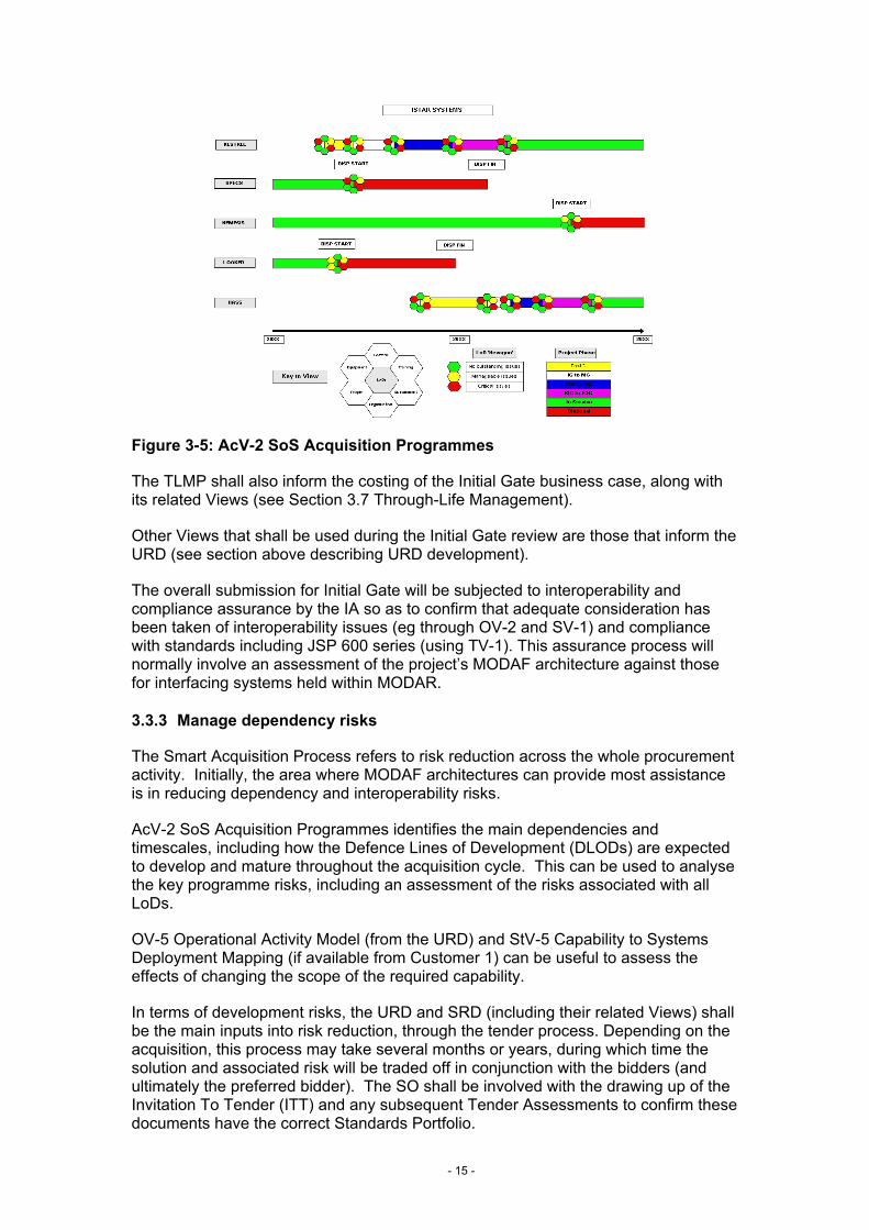
Figure 3-5: AcV-2 SoS Acquisition Programmes
The TLMP shall also inform the costing of the Initial Gate business case, along with its related Views (see Section 3.7 Through-Life Management).
Other Views that shall be used during the Initial Gate review are those that inform the URD (see section above describing URD development).
The overall submission for Initial Gate will be subjected to interoperability and compliance assurance by the IA so as to confirm that adequate consideration has been taken of interoperability issues (eg through OV-2 and SV-1) and compliance with standards including JSP 600 series (using TV-1). This assurance process will normally involve an assessment of the project’s MODAF architecture against those for interfacing systems held within MODAR.
3.3.3 Manage dependency risks
The Smart Acquisition Process refers to risk reduction across the whole procurement activity. Initially, the area where MODAF architectures can provide most assistance is in reducing dependency and interoperability risks.
AcV-2 SoS Acquisition Programmes identifies the main dependencies and timescales, including how the Defence Lines of Development (DLODs) are expected to develop and mature throughout the acquisition cycle. This can be used to analyse the key programme risks, including an assessment of the risks associated with all LoDs.
OV-5 Operational Activity Model (from the URD) and StV-5 Capability to Systems Deployment Mapping (if available from Customer 1) can be useful to assess the effects of changing the scope of the required capability.
In terms of development risks, the URD and SRD (including their related Views) shall be the main inputs into risk reduction, through the tender process. Depending on the acquisition, this process may take several months or years, during which time the solution and associated risk will be traded off in conjunction with the bidders (and ultimately the preferred bidder). The SO shall be involved with the drawing up of the Invitation To Tender (ITT) and any subsequent Tender Assessments to confirm these documents have the correct Standards Portfolio.
- 15 -
3.3.4 Main Gate
The Main Gate business case is a key deliverable, along with the SRD, from the Assessment Stage. The process and products are similar to those used at Initial Gate but with a higher degree of maturity expected at this stage. Specifically, the SRD, ITEAP and refined TLMP shall feed into this business case, along with the system design synthesis, to inform the decision on whether to proceed.
Again, the overall submission for Main Gate will be subjected to interoperability and compliance assurance by the IA so as to confirm that adequate consideration has been taken of interoperability issues (eg through OV-2 and SV-1) and compliance with standards including JSP 600 series (using TV-1). This assurance process will normally involve an assessment of the project’s MODAF architecture against those for interfacing systems held within MODAR.
3.3.5 Place contract(s) to meet the SRD
The SRD forms a key part of the contract, laying down the requirements to be met by the supplier. Therefore, the URD and SRD Views (see sections 3.4.1 and 3.4.3) shall help to illustrate the requirements, and ensure that the IPT and the supplier share the same understanding of the wider capability and system interface requirements, as well as the system functional and performance requirements.
3.3.6 Wind down of IPT
The architectural element of closing down the IPT shall be to ensure that the final architecture description left after disposal of the system is reflected in the architectural repository (MODAR), so that the repository reflects the removal of this system from service.
- 16 -
3.4 Requirements Management
This section describes the use of MODAF for the Requirements Management workstream within the IPT. The key activities for Requirements Management that may be helped by use of MODAF are:
• User Requirements Document (URD)
• Maintaining the linkage between User and System Requirements
• System Requirements Document (SRD)
• Integrated Testing, Evaluation and Acceptance Plan (ITEAP)
• Acceptance
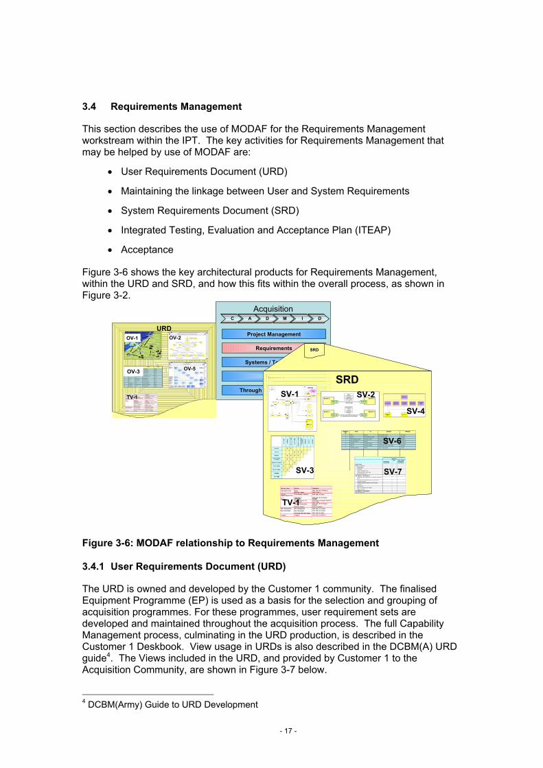
Figure 3-6 shows the key architectural products for Requirements Management, within the URD and SRD, and how this fits within the overall process, as shown in Figure 3-2.
AcquisitionC
Project Management
Requirements
Systems / Technology
Industry
Through Life Management
A D M I D
URDOV-2
OV-5
TV-1
OV-1
URDOV-2
OV-5
TV-1
OV-1
SRDSystem 5System 3
Port: 3c Port: 5f
TCP/IPEthernet
CAT 5 Cable
SMTP
3-5 e-mail
System 3System 1
Port: 1a Port: 3b1-3 Operational Feedback
PLCS DEX 7HTTP
TCP/IPBowman
TV-1
SV-1
LINK 16SPECS 2 TASK ORDERSPECS 2GROUND STATION7
BOWMANOPERATIONAL ISTAR TASK ORDERGROUND STATIONBDE HQ6
UHF RX/TXTACTICAL ISTAR INFOFIGHTING PATROLKESTREL5
UHF RX/TXKESTREL TASK ORDERKESTRELFIGHTING PATROL4
BOWMANPATROL TASKING ORDERFIGHTING PATROLMAIN OPERATING BASE3
BOWMANBG TASKING ORDERMAIN OPERATING BASEBDE HQ2
SAT COMMBDE TASKING ORDERBDE HQPJHQ1
MediumContentToFromNeedline ID
SV-3
SV-6
SV-4
SRD
SAT COMMSTRATEGIC ISTAR INFOPJHQAIRCRAFT CARRIER17
BOWMANOPERATIONAL ISTAR INFOBDE HQGROUND STATION16
LINK 16SPECS 2 TASK ORDERSPECS 2GROUND STATION7
SAT COMMSTRATEGIC ISTAR TASK ORDERAIRCRAFT CARRIERPJHQ8
LINK 16NEMESIS TASK ORDERNEMESISAIRCRAFT CARRIER9
LINK 16STRATEGIC ISTAR INFOAIRCRAFT CARRIERNEMESIS10
LINK 16STRATEGIC ISTAR INFOGROUND STATIONNEMESIS11
LINK 16OPERATIONAL ISTAR INFOGROUND STATIONSPECS 212
SAT COMMBDE AFTER ACTION REPORTPJHQBDE HQ13
BOWMANBG AFTER ACTION REPORTBDE HQMAIN OPERATING BASE14
BOWMANPATROL AFTER ACTION REPORTMAIN OPERATING BASEFIGHTING PATROL15
BOWMANOPERATIONAL ISTAR TASK ORDERGROUND STATIONBDE HQ6
UHF RX/TXTACTICAL ISTAR INFOFIGHTING PATROLKESTREL5
UHF RX/TXKESTREL TASK ORDERKESTRELFIGHTING PATROL4
BOWMANPATROL TASKING ORDERFIGHTING PATROLMAIN OPERATING BASE3
BOWMANBG TASKING ORDERMAIN OPERATING BASEBDE HQ2
SAT COMMBDE TASKING ORDERBDE HQPJHQ1
MediumContentToFromNeedline ID
OV-3
SV-2
SV-7
Figure 3-6: MODAF relationship to Requirements Management
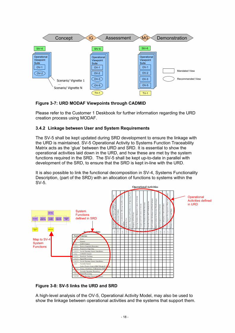
3.4.1 User Requirements Document (URD)
The URD is owned and developed by the Customer 1 community. The finalised Equipment Programme (EP) is used as a basis for the selection and grouping of acquisition programmes. For these programmes, user requirement sets are developed and maintained throughout the acquisition process. The full Capability Management process, culminating in the URD production, is described in the Customer 1 Deskbook. View usage in URDs is also described in the DCBM(A) URD guide4. The Views included in the URD, and provided by Customer 1 to the Acquisition Community, are shown in Figure 3-7 below.
- 17 -
4 DCBM(Army) Guide to URD Development
IG MG
TV-1
OV-2
OV-1
OV-3
OV-5
Operational Viewpoint Suite
StV-6
OV-1
Operational Viewpoint Suite
OV-2
OV-1
Operational Viewpoint Suite
OV-5
TV-1
OV-3
OV-2
Assessment DemonstrationConcept
Scenario/ Vignette 1
Scenario/ Vignette N…
StV-6 StV-6
Mandated View
Recommended View
Figure 3-7: URD MODAF Viewpoints through CADMID
Please refer to the Customer 1 Deskbook for further information regarding the URD creation process using MODAF.
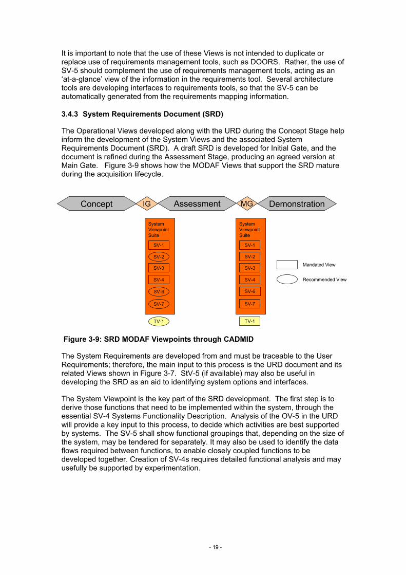
3.4.2 Linkage between User and System Requirements
The SV-5 shall be kept updated during SRD development to ensure the linkage with the URD is maintained. SV-5 Operational Activity to Systems Function Traceability Matrix acts as the ‘glue’ between the URD and SRD. It is essential to show the operational activities laid down in the URD, and how these are met by the system functions required in the SRD. The SV-5 shall be kept up-to-date in parallel with development of the SRD, to ensure that the SRD is kept in-line with the URD.
It is also possible to link the functional decomposition in SV-4, Systems Functionality Description, (part of the SRD) with an allocation of functions to systems within the SV-5.
Map to SV-4 System Functions
System Functions defined in SRD
Operational Activities defined in URD
Figure 3-8: SV-5 links the URD and SRD
A high-level analysis of the OV-5, Operational Activity Model, may also be used to show the linkage between operational activities and the systems that support them.
- 18 -
It is important to note that the use of these Views is not intended to duplicate or replace use of requirements management tools, such as DOORS. Rather, the use of SV-5 should complement the use of requirements management tools, acting as an ‘at-a-glance’ view of the information in the requirements tool. Several architecture tools are developing interfaces to requirements tools, so that the SV-5 can be automatically generated from the requirements mapping information.
3.4.3 System Requirements Document (SRD)
The Operational Views developed along with the URD during the Concept Stage help inform the development of the System Views and the associated System Requirements Document (SRD). A draft SRD is developed for Initial Gate, and the document is refined during the Assessment Stage, producing an agreed version at Main Gate. Figure 3-9 shows how the MODAF Views that support the SRD mature during the acquisition lifecycle.
IG MG
TV-1
SV-3
SV-1
System Viewpoint Suite
SV-6
TV-1
SV-2
Assessment DemonstrationConcept
SV-4
SV-7
SV-3
SV-1
System Viewpoint Suite
SV-4
SV-2
SV-6
SV-7
Mandated View
Recommended View
Figure 3-9: SRD MODAF Viewpoints through CADMID
The System Requirements are developed from and must be traceable to the User Requirements; therefore, the main input to this process is the URD document and its related Views shown in Figure 3-7. StV-5 (if available) may also be useful in developing the SRD as an aid to identifying system options and interfaces.
The System Viewpoint is the key part of the SRD development. The first step is to derive those functions that need to be implemented within the system, through the essential SV-4 Systems Functionality Description. Analysis of the OV-5 in the URD will provide a key input to this process, to decide which activities are best supported by systems. The SV-5 shall show functional groupings that, depending on the size of the system, may be tendered for separately. It may also be used to identify the data flows required between functions, to enable closely coupled functions to be developed together. Creation of SV-4s requires detailed functional analysis and may usefully be supported by experimentation.
- 19 -
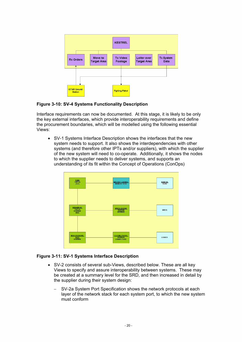
Figure 3-10: SV-4 Systems Functionality Description
Interface requirements can now be documented. At this stage, it is likely to be only the key external interfaces, which provide interoperability requirements and define the procurement boundaries, which will be modelled using the following essential Views:
• SV-1 Systems Interface Description shows the interfaces that the new system needs to support. It also shows the interdependencies with other systems (and therefore other IPTs and/or suppliers), with which the supplier of the new system will need to co-operate. Additionally, it shows the nodes to which the supplier needs to deliver systems, and supports an understanding of its fit within the Concept of Operations (ConOps)
Figure 3-11: SV-1 Systems Interface Description
• SV-2 consists of several sub-Views, described below. These are all key Views to specify and assure interoperability between systems. These may be created at a summary level for the SRD, and then increased in detail by the supplier during their system design:
− SV-2a System Port Specification shows the network protocols at each layer of the network stack for each system port, to which the new system must conform
- 20 -
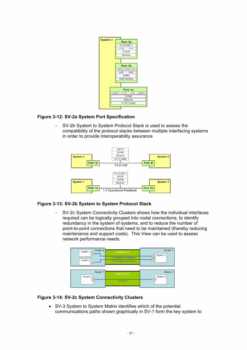
Figure 3-12: SV-2a System Port Specification
− SV-2b System to System Protocol Stack is used to assess the compatibility of the protocol stacks between multiple interfacing systems in order to provide interoperability assurance
Figure 3-13: SV-2b System to System Protocol Stack
− SV-2c System Connectivity Clusters shows how the individual interfaces required can be logically grouped into nodal connections, to identify redundancy in the system of systems, and to reduce the number of point-to-point connections that need to be maintained (thereby reducing maintenance and support costs). This View can be used to assess network performance needs.
Figure 3-14: SV-2c System Connectivity Clusters
• SV-3 System to System Matrix identifies which of the potential communications paths shown graphically in SV-1 form the key system to
- 21 -
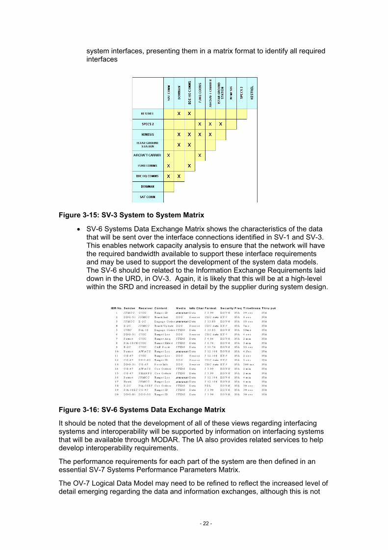
system interfaces, presenting them in a matrix format to identify all required interfaces
Figure 3-15: SV-3 System to System Matrix
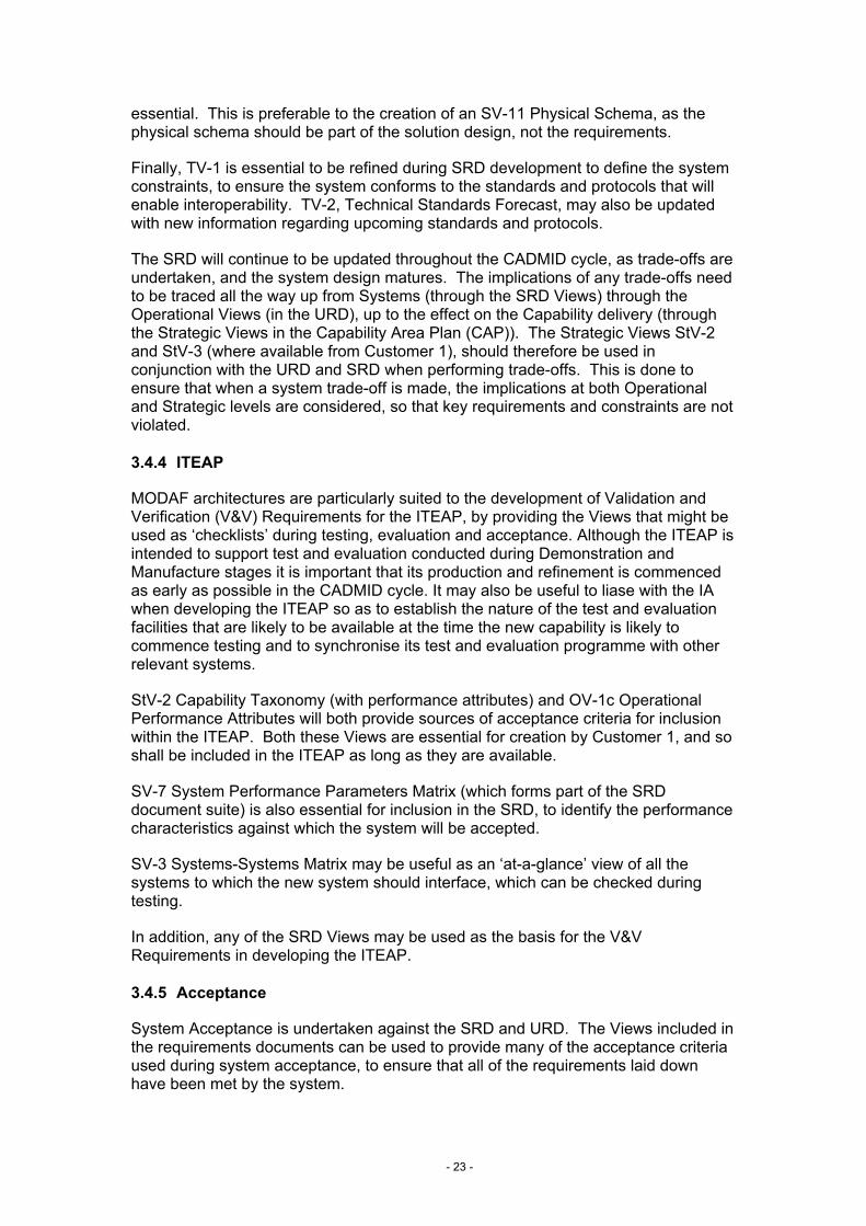
• SV-6 Systems Data Exchange Matrix shows the characteristics of the data that will be sent over the interface connections identified in SV-1 and SV-3. This enables network capacity analysis to ensure that the network will have the required bandwidth available to support these interface requirements and may be used to support the development of the system data models. The SV-6 should be related to the Information Exchange Requirements laid down in the URD, in OV-3. Again, it is likely that this will be at a high-level within the SRD and increased in detail by the supplier during system design.
Figure 3-16: SV-6 Systems Data Exchange Matrix
It should be noted that the development of all of these views regarding interfacing systems and interoperability will be supported by information on interfacing systems that will be available through MODAR. The IA also provides related services to help develop interoperability requirements.
The performance requirements for each part of the system are then defined in an essential SV-7 Systems Performance Parameters Matrix.
The OV-7 Logical Data Model may need to be refined to reflect the increased level of detail emerging regarding the data and information exchanges, although this is not
- 22 -
essential. This is preferable to the creation of an SV-11 Physical Schema, as the physical schema should be part of the solution design, not the requirements.
Finally, TV-1 is essential to be refined during SRD development to define the system constraints, to ensure the system conforms to the standards and protocols that will enable interoperability. TV-2, Technical Standards Forecast, may also be updated with new information regarding upcoming standards and protocols.
The SRD will continue to be updated throughout the CADMID cycle, as trade-offs are undertaken, and the system design matures. The implications of any trade-offs need to be traced all the way up from Systems (through the SRD Views) through the Operational Views (in the URD), up to the effect on the Capability delivery (through the Strategic Views in the Capability Area Plan (CAP)). The Strategic Views StV-2 and StV-3 (where available from Customer 1), should therefore be used in conjunction with the URD and SRD when performing trade-offs. This is done to ensure that when a system trade-off is made, the implications at both Operational and Strategic levels are considered, so that key requirements and constraints are not violated.
3.4.4 ITEAP
MODAF architectures are particularly suited to the development of Validation and Verification (V&V) Requirements for the ITEAP, by providing the Views that might be used as ‘checklists’ during testing, evaluation and acceptance. Although the ITEAP is intended to support test and evaluation conducted during Demonstration and Manufacture stages it is important that its production and refinement is commenced as early as possible in the CADMID cycle. It may also be useful to liase with the IA when developing the ITEAP so as to establish the nature of the test and evaluation facilities that are likely to be available at the time the new capability is likely to commence testing and to synchronise its test and evaluation programme with other relevant systems.
StV-2 Capability Taxonomy (with performance attributes) and OV-1c Operational Performance Attributes will both provide sources of acceptance criteria for inclusion within the ITEAP. Both these Views are essential for creation by Customer 1, and so shall be included in the ITEAP as long as they are available.
SV-7 System Performance Parameters Matrix (which forms part of the SRD document suite) is also essential for inclusion in the SRD, to identify the performance characteristics against which the system will be accepted.
SV-3 Systems-Systems Matrix may be useful as an ‘at-a-glance’ view of all the systems to which the new system should interface, which can be checked during testing.
In addition, any of the SRD Views may be used as the basis for the V&V Requirements in developing the ITEAP.
3.4.5 Acceptance
System Acceptance is undertaken against the SRD and URD. The Views included in the requirements documents can be used to provide many of the acceptance criteria used during system acceptance, to ensure that all of the requirements laid down have been met by the system.
- 23 -
The defence capability shall be confirmed against the Capability Requirements Document (CRD) and the Views contained therein. Please refer to the Customer 1 Deskbook for further information regarding the CRD development process and supporting Views.
The information / data exchanges detailed in OV-2, OV-3, SV-1 and SV-6 will be tested as part of Acceptance. Additional interoperability requirements can be derived from SV-2.
The interoperability requirements in OV-2 and SV-6, and the Information Exchange Requirements in OV-3 and SV-1 shall also be tested as part of Acceptance.
OV-5, OV-6 and SV-4 may be used in the development of test cases.
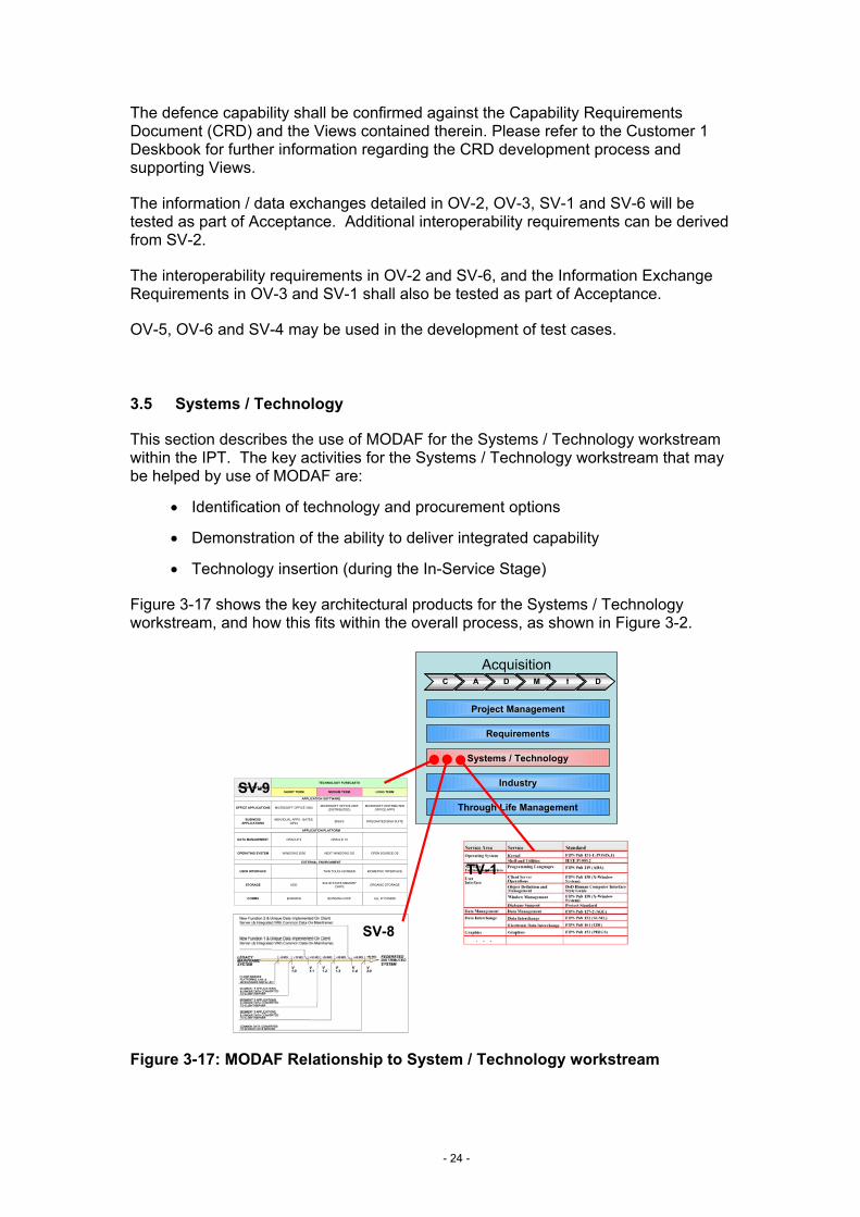
3.5 Systems / Technology
This section describes the use of MODAF for the Systems / Technology workstream within the IPT. The key activities for the Systems / Technology workstream that may be helped by use of MODAF are:
• Identification of technology and procurement options
• Demonstration of the ability to deliver integrated capability
• Technology insertion (during the In-Service Stage)
Figure 3-17 shows the key architectural products for the Systems / Technology workstream, and how this fits within the overall process, as shown in Figure 3-2.
AcquisitionCC
Project Management
Requirements
Systems / Technology
Industry
Through Life Management
AA DD MM II DD
TECHNOLOGY FORECASTSTECHNOLOGY AREA
SHORT TERM MEDIUM TERM LONG TERM
APPLICATION SOFTWARE
APPLICATION PLATFORM
EXTERNAL ENVIRONMENT
OFFICE APPLICATIONS
BUSINESSAPPLICATIONS
DATA MANAGEMENT
OPERATING SYSTEM
USER INTERFACE
STORAGE
COMMS
MICROSOFT OFFICE 2000 MICROSOFT OFFICE 2005(DISTRIBUTED)
MICROSOFT DISTRIBUTEDOFFICE APPS
INTEGRATED BISA SUITEBISA'SINDIVIDUAL APPS - BATES,QP24
ORACLE 9 ORACLE 10
OPEN SOURCE OSNEXT WINDOWS OSWINDOWS 2000
THIN TOUCH SCREEN BIOMETRIC INTERFACE
HDD SOLID STATE MEMORYCHIPS ORGANIC STORAGE
ALL IP COMMSBOWMAN+VOIPBOWMAN
SV-9
SV-8
TV-1
Figure 3-17: MODAF Relationship to System / Technology workstream
- 24 -
3.5.1 Identify technology and procurement options
The undertaking of this process described here relates to the current CADMID process. It is understood that this is subject to change with the AfNEC (Acquisition for NEC) work, looking at use of alternative procurement and delivery options (such as more off-the-shelf (OTS) and re-use of existing systems to deliver additional capability). When purchasing Commercial OTS (COTS) equipment it is important not to over-specify the standards – or else additional cost and risk may be transferred back to MOD, negating the benefits of using a COTS solution.
StV-3 Capability Phasing, provided by Customer 1, shows the IPT the broader picture of the overall capability delivery and which other systems are being acquired, upgraded or retired in the time period that the new capability is being procured. This may help inform decisions regarding common technologies and procurement options across a number of related capabilities, such as applications delivering in the same epoch agree on a common target Operating System between themselves.
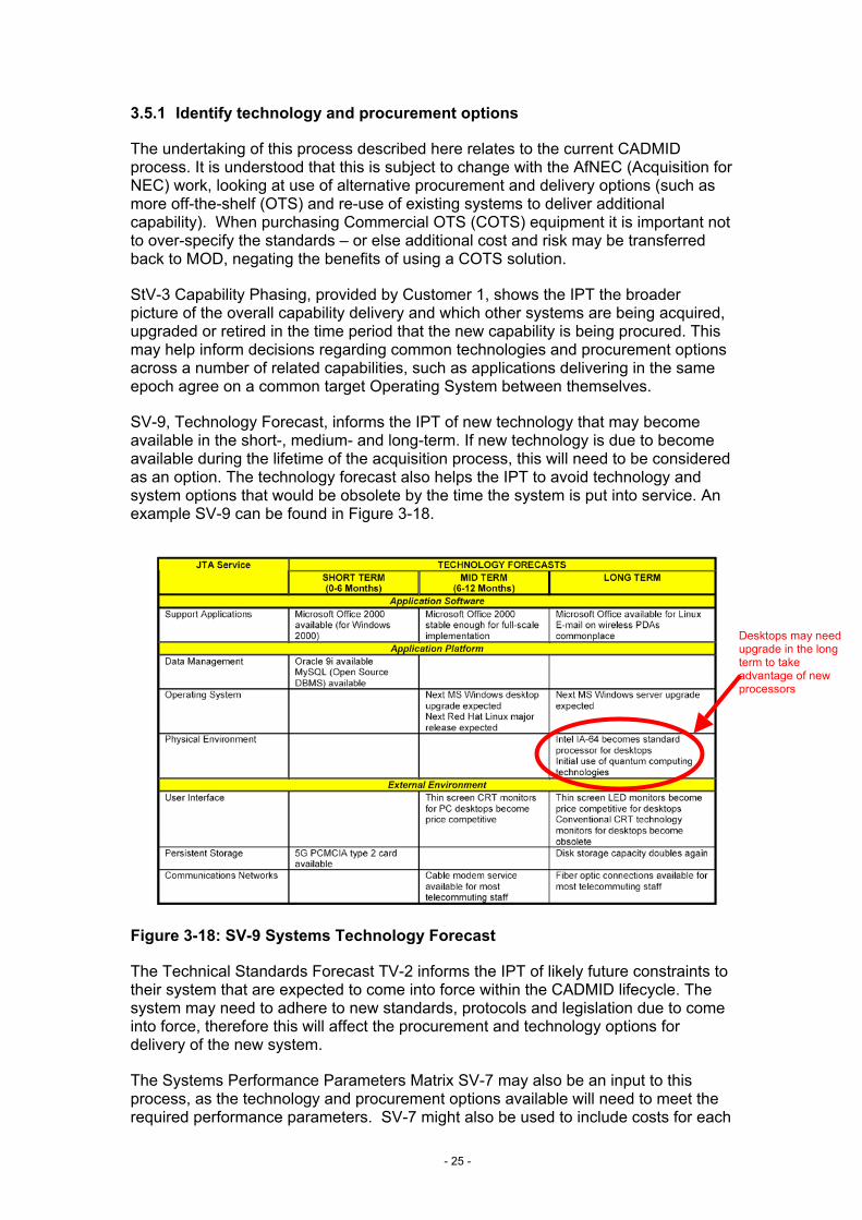
SV-9, Technology Forecast, informs the IPT of new technology that may become available in the short-, medium- and long-term. If new technology is due to become available during the lifetime of the acquisition process, this will need to be considered as an option. The technology forecast also helps the IPT to avoid technology and system options that would be obsolete by the time the system is put into service. An example SV-9 can be found in Figure 3-18.
Desktops may need upgrade in the long term to take advantage of new processors
Figure 3-18: SV-9 Systems Technology Forecast
The Technical Standards Forecast TV-2 informs the IPT of likely future constraints to their system that are expected to come into force within the CADMID lifecycle. The system may need to adhere to new standards, protocols and legislation due to come into force, therefore this will affect the procurement and technology options for delivery of the new system.
The Systems Performance Parameters Matrix SV-7 may also be an input to this process, as the technology and procurement options available will need to meet the required performance parameters. SV-7 might also be used to include costs for each
- 25 -
option, through cost / performance parameters, to feed into the Balance of Investment decision.
Once the technology and procurement options have been identified and reviewed, and those meriting further investigation identified, TV-1 Technical Standards Profile is essential to be created / updated to aid the analysis of these options, and the development of the chosen option.
TV-1 Technical Standards Profile shall show the constraints that apply to each option (with a separate TV-1 created for each option being explored). This feeds into the requirements documents, and informs the options chosen, as, generally, the more constraints on a system the more costly it will be to procure. When populating the TV-1 only use the minimum number of Treaties, Legislation and Standards that underpin the requirements. An example TV-1 is shown in Figure 3-4.
It is essential to keep SV-9 Systems Technology Forecast and TV-2 Technical Standards Forecast updated throughout the CADMID cycle as technology and standards develop, and the future technological landscape becomes clearer. The SO, in conjunction with Industry, is responsible for monitoring technological and standards development, to ensure that the solution to be delivered will not quickly become obsolete.
3.5.2 Demonstrate ability to deliver integrated capability
Once the option has been chosen during the Concept and Assessment Stages, it must be shown to deliver the requirements during the Demonstration Stage. The following Views will support technology demonstrators / prototypes in demonstrating that the requirements are met by the chosen system solution.
OV-2 Operational Node Connectivity Description and SV-6 Systems Data Exchange Matrix shows how the system will meet the interoperability requirements, to provide an integrated capability.
OV-3 Operational Information Exchange Matrix and SV-1 Systems Interface Description shows the Information Exchange Requirements (IERs), which should be included in the contract, to ensure integration, and how these are being met at a physical connectivity level.
OV-1c Operational Performance Parameters and SV-7 System Performance Parameters Matrix show the required operational and system performance to be delivered by the solution.
3.5.3 Technology insertion
Once the system is in the In-Service Stage, the technology evolution and evolving standards may drive obsolescence of system elements. The TLMP will be updated using inputs from the SV-9 and TV-2 to reflect this changing technology landscape, and upgrades, improvements or replacement initiated as needed.
3.6 Industry / Suppliers
This section describes the use of MODAF for the Industry / Supplier liaison within the IPT. The key activities for the Industry / Suppliers in conjunction with the IPT that may be helped by use of MODAF are:
• Initial Industry involvement
- 26 -
• System synthesis
• Contract negotiation
• Solution delivery
• Carrying out any agreed upgrades or improvements once the system is in the In-Service Stage
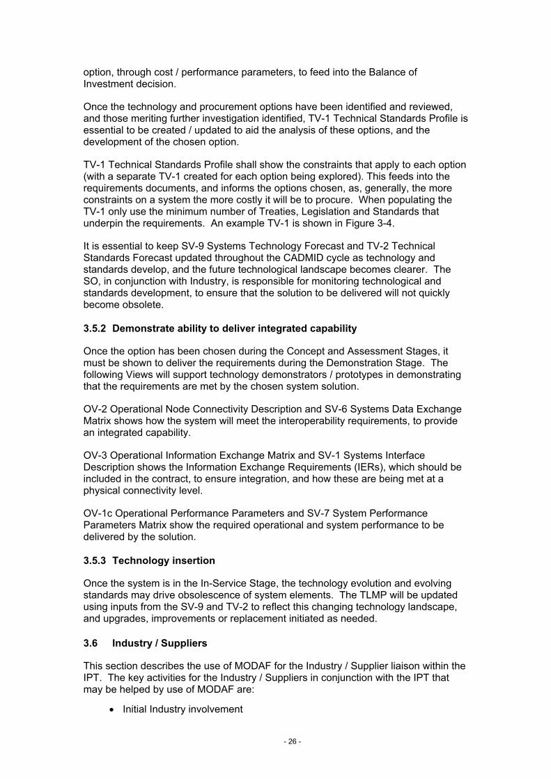
Figure 3-19 shows the key architectural products for the Industry / Supplier liaison, and how this fits within the overall process, as shown in Figure 3-2.
AcquisitionC
Project Management
Requirements
Systems / Technology
Industry
Through Life Management
A D M I D
SRDSystem 5System 3
Port: 3c Port: 5f
TCP/IPEthernet
CAT 5 Cable
SMTP
3-5 e-mail
System 3System 1
Port: 1a Port: 3b1-3 Operational Feedback
PLCS DEX 7HTTP
TCP/IPBowman
TV-1
SV-1
LINK 16SPECS 2 TASK ORDERSPECS 2GROUND STATION7
BOWMANOPERATIONAL ISTAR TASK ORDERGROUND STATIONBDE HQ6
UHF RX/TXTACTICAL ISTAR INFOFIGHTING PATROLKESTREL5
UHF RX/TXKESTREL TASK ORDERKESTRELFIGHTING PATROL4
BOWMANPATROL TASKING ORDERFIGHTING PATROLMAIN OPERATING BASE3
BOWMANBG TASKING ORDERMAIN OPERATING BASEBDE HQ2
SAT COMMBDE TASKING ORDERBDE HQPJHQ1
MediumContentToFromNeedline ID
LINK 16SPECS 2 TASK ORDERSPECS 2GROUND STATION7
BOWMANOPERATIONAL ISTAR TASK ORDERGROUND STATIONBDE HQ6
UHF RX/TXTACTICAL ISTAR INFOFIGHTING PATROLKESTREL5
UHF RX/TXKESTREL TASK ORDERKESTRELFIGHTING PATROL4
BOWMANPATROL TASKING ORDERFIGHTING PATROLMAIN OPERATING BASE3
BOWMANBG TASKING ORDERMAIN OPERATING BASEBDE HQ2
SAT COMMBDE TASKING ORDERBDE HQPJHQ1
MediumContentToFromNeedline ID
SV-3
SV-6
SV-4
SRD
SV-2
SV-7
URDOV-2
OV-5
TV-1
OV-1
URDOV-2
OV-5
TV-1
OV-1
SAT COMMSTRATEGIC ISTAR INFOPJHQAIRCRAFT CARRIER17
BOWMANOPERATIONAL ISTAR INFOBDE HQGROUND STATION16
LINK 16SPECS 2 TASK ORDERSPECS 2GROUND STATION7
SAT COMMSTRATEGIC ISTAR TASK ORDERAIRCRAFT CARRIERPJHQ8
LINK 16NEMESIS TASK ORDERNEMESISAIRCRAFT CARRIER9
LINK 16STRATEGIC ISTAR INFOAIRCRAFT CARRIERNEMESIS10
LINK 16STRATEGIC ISTAR INFOGROUND STATIONNEMESIS11
LINK 16OPERATIONAL ISTAR INFOGROUND STATIONSPECS 212
SAT COMMBDE AFTER ACTION REPORTPJHQBDE HQ13
BOWMANBG AFTER ACTION REPORTBDE HQMAIN OPERATING BASE14
BOWMANPATROL AFTER ACTION REPORTMAIN OPERATING BASEFIGHTING PATROL15
BOWMANOPERATIONAL ISTAR TASK ORDERGROUND STATIONBDE HQ6
UHF RX/TXTACTICAL ISTAR INFOFIGHTING PATROLKESTREL5
UHF RX/TXKESTREL TASK ORDERKESTRELFIGHTING PATROL4
BOWMANPATROL TASKING ORDERFIGHTING PATROLMAIN OPERATING BASE3
BOWMANBG TASKING ORDERMAIN OPERATING BASEBDE HQ2
SAT COMMBDE TASKING ORDERBDE HQPJHQ1
MediumContentToFromNeedline ID
OV-3
Figure 3-19: MODAF Relationship to Industry workstream
3.6.1 Involve Industry
The MOD Defence Industrial Policy (2002) provides the framework for MOD’s relationship with the defence industry. It makes clear that, right from the start of acquisition projects, MOD is being more transparent about the factors that affect acquisition decisions. MODAF can play a significant role in this transparency by providing early and clear visibility of the context, constraints and interfaces of the required new capability. As far as possible, these will be made clear to potential bidders at the outset to enable them to frame their bids accordingly.
Engaging industry during the first stages of the project cycle is important, for example by seeking industry’s views on initial procurement strategies and their help during the early stages of an evolving requirement.
MODAF Views provide a useful tool in the engagement of industry partners. Their help can be obtained in developing the Views required for Initial and Main Gate. For example, industry opinions on the practicality of the performance requirements in
- 27 -
OV-1c as the system contributions become known, and the resultant effect on the cost, delivery timescale and maintainability of the solution, should be sought prior to formalising these as requirements.
The Operational Viewpoint is particularly useful in the initial engagement with Industry in identifying the operational context and use cases for the new capability. OV-1 and OV-2 (where available from Customer 1) shall be used for industry involvement during the Concept Stage.
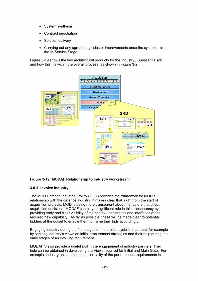
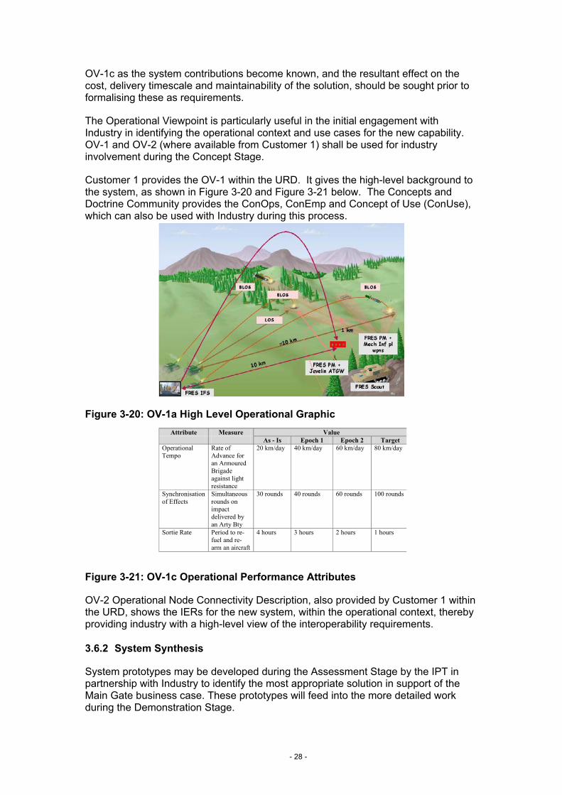
Customer 1 provides the OV-1 within the URD. It gives the high-level background to the system, as shown in Figure 3-20 and Figure 3-21 below. The Concepts and Doctrine Community provides the ConOps, ConEmp and Concept of Use (ConUse), which can also be used with Industry during this process.
Figure 3-20: OV-1a High Level Operational Graphic Attribute Measure Value
As - Is Epoch 1 Epoch 2 Target Operational Tempo
Rate of Advance for an Armoured Brigade against light resistance
20 km/day 40 km/day 60 km/day 80 km/day
Synchronisation of Effects
Simultaneous rounds on impact delivered by an Arty Bty
30 rounds 40 rounds 60 rounds 100 rounds
Sortie Rate Period to re-fuel and re-arm an aircraft
4 hours 3 hours 2 hours 1 hours
Figure 3-21: OV-1c Operational Performance Attributes
OV-2 Operational Node Connectivity Description, also provided by Customer 1 within the URD, shows the IERs for the new system, within the operational context, thereby providing industry with a high-level view of the interoperability requirements.
3.6.2 System Synthesis
System prototypes may be developed during the Assessment Stage by the IPT in partnership with Industry to identify the most appropriate solution in support of the Main Gate business case. These prototypes will feed into the more detailed work during the Demonstration Stage.
- 28 -
Inputs to this process are:
• The SRD Views, developed by the Requirements workstream
• SV-9 Systems Technology Forecast, to provide insight into how technology is evolving in relation to this system, developed by the Systems and Technology Workstream
• TV-2 Technical Standards Forecast, which, as discussed in the Concept Stage, shows how the system needs to be ‘future-proofed’ for the new accepted standards, also developed by the Systems and Technology Workstream.
3.6.3 Negotiate contract
The architectural model developed alongside the URD and SRD will assist the IPT in their contract negotiations. Not only will this provide industry with a clearer system context and set of assumptions but it will also identify the required system interfaces and standards. Furthermore, the boundaries within which system elements can be traded-off will be apparent. During negotiations, the cost and time implications of the architectural components can also be finalised, and used as a basis for updating the TLMP with more detailed plans.
3.6.4 Deliver the solution
The supplier will have responsibility to deliver the solution in accordance with the contract and SRD. As part of the solution delivery, the supplier may find it helpful to use some of the MODAF Views as part of their detailed design work, although this is not essential and will depend on both the supplier, supporting tools and nature of the system to be developed.
3.6.5 Carry out any agreed upgrades or improvements
Upgrades and improvements are identified by Customer 2, and fed back into the EP for management by Customer 1. These will usually spawn a new CADMID cycle within the responsible IPT and, as such, will utilise the same MODAF Views as described in this Deskbook.
The need for upgrades or improvements are also informed by the following: StV-2, Capability Functions; StV-3, Capability Phasing, (both of which are owned and updated by the Customer 1 function); the SV-2 suite of interoperability Views; and SV-8, the Systems Evolution Description, essential in the TLMP, that shows the planned upgrade path for the system.
3.7 Through-Life Management
This section describes the use of MODAF for Through-Life Management within the IPT. The key activities for Through-Life Management that may be helped by use of MODAF are:
• Through-Life Management Planning (TLMP)
• Integrated Logistics Support
- 29 -
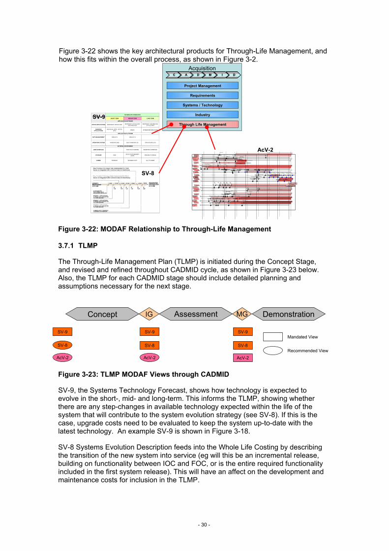
Figure 3-22 shows the key architectural products for Through-Life Management, and how this fits within the overall process, as shown in Figure 3-2.
AcquisitionCC
Project Management
Requirements
Systems / Technology
Industry
Through Life Management
AA DD MM II DD
TECHNOLOGY FORECASTSTECHNOLOGY AREA
SHORT TERM MEDIUM TERM LONG TERM
APPLICATION SOFTWARE
APPLICATION PLATFORM
EXTERNAL ENVIRONMENT
OFFICE APPLICATIONS
BUSINESSAPPLICATIONS
DATA MANAGEMENT
OPERATING SYSTEM
USER INTERFACE
STORAGE
COMMS
MICROSOFT OFFICE 2000 MICROSOFT OFFICE 2005(DISTRIBUTED)
MICROSOFT DISTRIBUTEDOFFICE APPS
INTEGRATED BISA SUITEBISA'SINDIVIDUAL APPS - BATES,QP24
ORACLE 9 ORACLE 10
OPEN SOURCE OSNEXT WINDOWS OSWINDOWS 2000
THIN TOUCH SCREEN BIOMETRIC INTERFACE
HDD SOLID STATE MEMORYCHIPS ORGANIC STORAGE
ALL IP COMMSBOWMAN+VOIPBOWMAN
SV-9
SV-8
Operations
,2& )2&
:DWFKNHHSHU
2FW 'HF51&66
%/'&66,) /3'5
)DOFRQ,QFUHPHQW$
0DLQ*DWH,QF$,QLWLDO*D WH,QF%,QF$'0&WW/H W
)LHOG7ULDOV'HOLYHU7UDQFKH 'HOLYHU7UDQFKH 'HOLYHU7UDQFKH,QF$,6'
,QF$,6'0DLQ*DWH,QF%
'HOLYHU7UDQFKH
'HOLYHU7UDQFKH'HOLYHU7UDQFKH
)DOFRQ,QFUHPHQW%
'0&WW/H W
)DOFRQ,QFUHPHQW&
,QLWLDO*D WH,QF&
)LHOG7ULDOV,QF%'HOLYHU7UDQFKH'HOLYHU7UDQFKH'HOLYHU7UDQFKH'HOLYHU7UDQFKH'HOLYHU7UDQFKH'HOLYHU7UDQFKH
'HOLYHU57768SJUDGH'HOLYHU7UDQFKH 'HOLYHU7UDQFKH
'HOLYHU7UDQFKH
7HFKQRORJ\UHIUHVKHV
&RUPRUDQW
0D\,6'
0D\)2&
2FW)2&
'HF,6'
0D\06$0
-DQ06$0
2FW 'HF0DU9HUVLRQ
'HF9HUVLRQ
0HUJHG&66-2&6"-2&6
&RPPRQ2SHUDWLRQDO&RPPDQG6XSSRU W6\VWHP"
6HS,QF%$VVHVV3KDVH&WW/H W
$6725
2S7ULDOVDF*6 2S7ULDOVDF*6 %$786WULDO,6' /LP&5
,2&)XOO&5&WWRULQWHJWULDOV
-&6/RJ
3KDVH,QF3KDVH,QF,2&
)2&)2&
',,
0DLQ*DWH ,6' )2&
%2:0$1
&,3
5$)&&,6
,6' /LWWRUDO25'$025'
(&,32)7 ,&,3WR',/ )&,3WR',/)&%,6$,2&
6WDJH 6WDJH
"
)XOO)&%,6$
/DQG25'%RZPDQ,2& %RZPDQ,6'&DSDELOLW\25'&DSDELOLW\%GH2)7
,2& )2&
:DWFKNHHSHU
2FW 'HF51&66
,2& )2&
:DWFKNHHSHU
2FW 'HF51&66
%/'&66,) /3'5
)DOFRQ,QFUHPHQW$
0DLQ*DWH,QF$,QLWLDO*D WH,QF%,QF$'0&WW/H W
)LHOG7ULDOV'HOLYHU7UDQFKH 'HOLYHU7UDQFKH 'HOLYHU7UDQFKH,QF$,6'
,QF$,6'0DLQ*DWH,QF%
'HOLYHU7UDQFKH
'HOLYHU7UDQFKH'HOLYHU7UDQFKH
%/'&66,) /3'5
)DOFRQ,QFUHPHQW$
0DLQ*DWH,QF$,QLWLDO*D WH,QF%,QF$'0&WW/H W
)LHOG7ULDOV'HOLYHU7UDQFKH 'HOLYHU7UDQFKH 'HOLYHU7UDQFKH,QF$,6'
,QF$,6'0DLQ*DWH,QF%
'HOLYHU7UDQFKH
'HOLYHU7UDQFKH'HOLYHU7UDQFKH
)DOFRQ,QFUHPHQW%
'0&WW/H W
)DOFRQ,QFUHPHQW&
,QLWLDO*D WH,QF&
)LHOG7ULDOV,QF%'HOLYHU7UDQFKH'HOLYHU7UDQFKH'HOLYHU7UDQFKH'HOLYHU7UDQFKH'HOLYHU7UDQFKH'HOLYHU7UDQFKH
'HOLYHU57768SJUDGH'HOLYHU7UDQFKH 'HOLYHU7UDQFKH
'HOLYHU7UDQFKH
)DOFRQ,QFUHPHQW%
'0&WW/H W
)DOFRQ,QFUHPHQW&
,QLWLDO*D WH,QF&
)LHOG7ULDOV,QF%'HOLYHU7UDQFKH'HOLYHU7UDQFKH'HOLYHU7UDQFKH'HOLYHU7UDQFKH'HOLYHU7UDQFKH'HOLYHU7UDQFKH
'HOLYHU57768SJUDGH'HOLYHU7UDQFKH 'HOLYHU7UDQFKH
'HOLYHU7UDQFKH
7HFKQRORJ\UHIUHVKHV
&RUPRUDQW
0D\,6'
0D\)2&
2FW)2&
'HF,6'
0D\06$0
-DQ06$0
2FW 'HF0DU9HUVLRQ
'HF9HUVLRQ
0HUJHG&66-2&6"-2&6
&RPPRQ2SHUDWLRQDO&RPPDQG6XSSRU W6\VWHP"
6HS,QF%$VVHVV3KDVH&WW/H W
7HFKQRORJ\UHIUHVKHV
&RUPRUDQW
0D\,6'
0D\)2&
2FW)2&
'HF,6'
0D\06$0
-DQ06$0
2FW 'HF0DU9HUVLRQ
'HF9HUVLRQ
0HUJHG&66-2&6"-2&6
&RPPRQ2SHUDWLRQDO&RPPDQG6XSSRU W6\VWHP"
6HS,QF%$VVHVV3KDVH&WW/H W
$6725
2S7ULDOVDF*6 2S7ULDOVDF*6 %$786WULDO,6' /LP&5
,2&)XOO&5&WWRULQWHJWULDOV
-&6/RJ
3KDVH,QF3KDVH,QF,2&
)2&
$6725
2S7ULDOVDF*6 2S7ULDOVDF*6 %$786WULDO,6' /LP&5
,2&)XOO&5&WWRULQWHJWULDOV
-&6/RJ
3KDVH,QF3KDVH,QF,2&
)2&)2&
',,
0DLQ*DWH ,6' )2&
%2:0$1
)2&
',,
0DLQ*DWH ,6' )2&
%2:0$1
&,3
5$)&&,6
,6' /LWWRUDO25'$025'
(&,32)7 ,&,3WR',/ )&,3WR',/)&%,6$,2&
6WDJH 6WDJH
"
)XOO)&%,6$
/DQG25'%RZPDQ,2& %RZPDQ,6'&DSDELOLW\25'&DSDELOLW\
&,3
5$)&&,6
,6' /LWWRUDO25'$025'
(&,32)7 ,&,3WR',/ )&,3WR',/)&%,6$,2&
6WDJH 6WDJH
"
)XOO)&%,6$
/DQG25'%RZPDQ,2& %RZPDQ,6'&DSDELOLW\25'&DSDELOLW\%GH2)7
AcV-2
Figure 3-22: MODAF Relationship to Through-Life Management
3.7.1 TLMP
The Through-Life Management Plan (TLMP) is initiated during the Concept Stage, and revised and refined throughout CADMID cycle, as shown in Figure 3-23 below. Also, the TLMP for each CADMID stage should include detailed planning and assumptions necessary for the next stage.
IG MG
SV-9
AcV-2
SV-8
Assessment DemonstrationConcept
SV-9
SV-8
AcV-2
SV-9
SV-8
AcV-2
Mandated View
Recommended View
Figure 3-23: TLMP MODAF Views through CADMID
SV-9, the Systems Technology Forecast, shows how technology is expected to evolve in the short-, mid- and long-term. This informs the TLMP, showing whether there are any step-changes in available technology expected within the life of the system that will contribute to the system evolution strategy (see SV-8). If this is the case, upgrade costs need to be evaluated to keep the system up-to-date with the latest technology. An example SV-9 is shown in Figure 3-18.
SV-8 Systems Evolution Description feeds into the Whole Life Costing by describing the transition of the new system into service (eg will this be an incremental release, building on functionality between IOC and FOC, or is the entire required functionality included in the first system release). This will have an affect on the development and maintenance costs for inclusion in the TLMP.
- 30 -
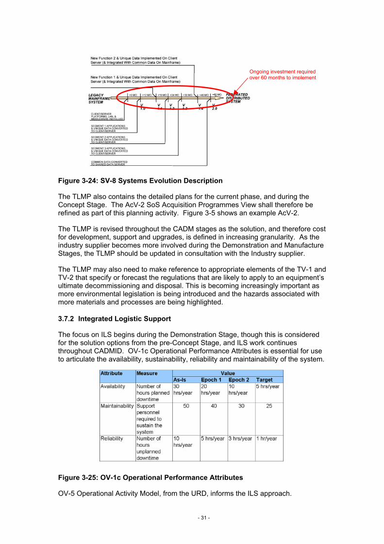
Ongoing investment required over 60 months to implement
Figure 3-24: SV-8 Systems Evolution Description
The TLMP also contains the detailed plans for the current phase, and during the Concept Stage. The AcV-2 SoS Acquisition Programmes View shall therefore be refined as part of this planning activity. Figure 3-5 shows an example AcV-2.
The TLMP is revised throughout the CADM stages as the solution, and therefore cost for development, support and upgrades, is defined in increasing granularity. As the industry supplier becomes more involved during the Demonstration and Manufacture Stages, the TLMP should be updated in consultation with the Industry supplier.
The TLMP may also need to make reference to appropriate elements of the TV-1 and TV-2 that specify or forecast the regulations that are likely to apply to an equipment’s ultimate decommissioning and disposal. This is becoming increasingly important as more environmental legislation is being introduced and the hazards associated with more materials and processes are being highlighted.
3.7.2 Integrated Logistic Support
The focus on ILS begins during the Demonstration Stage, though this is considered for the solution options from the pre-Concept Stage, and ILS work continues throughout CADMID. OV-1c Operational Performance Attributes is essential for use to articulate the availability, sustainability, reliability and maintainability of the system.
Figure 3-25: OV-1c Operational Performance Attributes
OV-5 Operational Activity Model, from the URD, informs the ILS approach.
- 31 -

- 32 -
4. Worked Example
This section will present a worked example of MODAF View development in the Acquisition community. It is intended to add clarity, and realism, to the overview of the MODAF View relationship to the CADMID / CADMIT process provided in the previous section.
This section will be updated once example material is available from the FRES MODAF pilot. For an example of what information this section will provide, please see section 4 of the Customer 1 Deskbook, available on www.modaf.com.
- 33 -

- 34 -
5. Document Maintenance
It is intended that the MODAF product suite will evolve through time in order to reflect learning from experience, changes to the MOD’s processes and the evolution of architectural best practice. A change control process will be established for all MODAF products and suggestions upon the refinement / improvement of this and related products is welcome. The formal MODAF change control process shall be published in due course. In the interim, suggestions should be forwarded to the MODAF project manager:
Mrs Kathy Lamb, EC CCII I2b
Tel: 0207 807 8884
e-mail: [email protected]