Embed Size (px)
Citation preview

Juniper Network, Inc.1194 N. Mathilda AvenueSunnyvale, CA 94089 USA408-745-2000www.juniper.net
Part Number: 730-9502-0217 Rev. D
Mobility Point™ Hardware Installation Guide 7.4

ii Mobility Point Hardware Installation Guide 7.4
Copyright © 2011, Juniper Networks, Inc. All rights reserved.
TrademarksJuniper Networks, the Juniper Networks logo, NetScreen, NetScreen Technologies, the NetScreen logo, NetScreen-Global Pro, ScreenOS, and GigaScreen are registered trademarks of Juniper Networks, Inc. in the United States and other countries.
The following are trademarks of Juniper Networks, Inc.: ERX, ESP, E-series, Instant Virtual Extranet, Internet Processor, J2300, J4300, J6300, J-Protect, J-series, J-Web, JUNOS, JUNOScope, JUNOScript, JUNOSe, M5, M7i, M10, M10i, M20, M40, M40e, M160, M320, M-series, MMD, NetScreen-5GT, NetScreen-5XP, NetScreen-5XT, NetScreen-25, NetScreen-50, NetScreen-204, NetScreen-208, NetScreen-500, NetScreen-5200, NetScreen-5400, NetScreen-IDP 10, NetScreen-IDP 100, NetScreen-IDP 500, NetScreen-Remote Security Client, NetScreen-Remote VPN Client, NetScreen-SA 1000 Series, NetScreen-SA 3000 Series, NetScreen-SA 5000 Series, NetScreen-SA Central Manager, NetScreen Secure Access, NetScreen-SM 3000, NetScreen-Security Manager, NMC-RX, SDX, Stateful Signature, T320, T640, T-series, and TX Matrix. All other trademarks, service marks, registered trademarks, or registered service marks are the property of their respective owners. All specifications are subject to change without notice. Juniper Networks assumes no responsibility for any inaccuracies in this document. Juniper Networks reserves the right to change, modify, transfer, or otherwise revise this publication without notice.
DisclaimerAll statements, specifications, recommendations, and technical information are current or planned as of the date of the publication of this document. They are reliable as of the time of this writing and are presented without warranty of any kind, expressed or implied. In an effort to continuously improve the product and add features, JuniperNetworks reserves the right to change any specifications contained in this document without prior notice of any kind.
Copyright © 2011, Juniper Networks, Inc. All rights reserved.
Juniper Networks, the Juniper Networks logo, NetScreen, NetScreen Technologies, the NetScreen logo, NetScreen-Global Pro, ScreenOS, and GigaScreen are registered trademarks of Juniper Networks, Inc. in the United States and other countries.
The following are trademarks of Juniper Networks, Inc.: ERX, ESP, E-series, Instant Virtual Extranet, Internet Processor, J2300, J4300, J6300, J-Protect, J-series, J-Web, JUNOS, JUNOScope, JUNOScript, JUNOSe, M5, M7i, M10, M10i, M20, M40, M40e, M160, M320, M-series, MMD, NetScreen-5GT, NetScreen-5XP, NetScreen-5XT, NetScreen-25, NetScreen-50, NetScreen-204, NetScreen-208, NetScreen-500, NetScreen-5200, NetScreen-5400, NetScreen-IDP 10, NetScreen-IDP 100, NetScreen-IDP 500, NetScreen-Remote Security Client, NetScreen-Remote VPN Client, NetScreen-SA 1000 Series, NetScreen-SA 3000 Series, NetScreen-SA 5000 Series, NetScreen-SA Central Manager, NetScreen Secure Access, NetScreen-SM 3000, NetScreen-Security Manager, NMC-RX, SDX, Stateful Signature, T320, T640, T-series, and TX Matrix. All other trademarks, service marks, registered trademarks, or registered service marks are the property of their respective owners. All specifications are subject to change without notice. Juniper Networks assumes no responsibility for any inaccuracies in this document. Juniper Networks reserves the right to change, modify, transfer, or otherwise revise this publication without notice.

Indoor Mobility Point Installation Guide iii
Table of Contents
About This GuideJuniper Networks Mobility System . . . . . . . . . . . . . . . . . . . . . . . . . . . . . . . . . . . . . . . . . . . . . .i-vWarranty and Software Licenses . . . . . . . . . . . . . . . . . . . . . . . . . . . . . . . . . . . . . . . . . . . . . i-viii
Chapter 1 MP OverviewExternal Hardware Features . . . . . . . . . . . . . . . . . . . . . . . . . . . . . . . . . . . . . . . . . . . . . . . . . . 1-2
Ethernet Ports . . . . . . . . . . . . . . . . . . . . . . . . . . . . . . . . . . . . . . . . . . . . . . . . . . . . . . . . . . . . 1-5External Antenna Connectors . . . . . . . . . . . . . . . . . . . . . . . . . . . . . . . . . . . . . . . . . . . . . . . . 1-6Kensington Security Slot. . . . . . . . . . . . . . . . . . . . . . . . . . . . . . . . . . . . . . . . . . . . . . . . . . . . 1-7MP Mounting Options . . . . . . . . . . . . . . . . . . . . . . . . . . . . . . . . . . . . . . . . . . . . . . . . . . . . . . 1-8Status LEDs . . . . . . . . . . . . . . . . . . . . . . . . . . . . . . . . . . . . . . . . . . . . . . . . . . . . . . . . . . . . . 1-8
Connection Options . . . . . . . . . . . . . . . . . . . . . . . . . . . . . . . . . . . . . . . . . . . . . . . . . . . . . . . . 1-10
Chapter 2 Installing and Connecting an Indoor MPUnpacking an MP. . . . . . . . . . . . . . . . . . . . . . . . . . . . . . . . . . . . . . . . . . . . . . . . . . . . . . . . . . . 2-1
MP-82 Package Contents . . . . . . . . . . . . . . . . . . . . . . . . . . . . . . . . . . . . . . . . . . . . . . . . . . . 2-1Installation Requirements and Recommendations . . . . . . . . . . . . . . . . . . . . . . . . . . . . . . . . . 2-2
RingMaster Network Plan and Work Orders. . . . . . . . . . . . . . . . . . . . . . . . . . . . . . . . . . . . . 2-2MX Recommendation . . . . . . . . . . . . . . . . . . . . . . . . . . . . . . . . . . . . . . . . . . . . . . . . . . . . . . 2-3Wall Installation Recommendations . . . . . . . . . . . . . . . . . . . . . . . . . . . . . . . . . . . . . . . . . . . 2-3MP Radio Safety Advisories . . . . . . . . . . . . . . . . . . . . . . . . . . . . . . . . . . . . . . . . . . . . . . . . . 2-3
Radio Frequency Exposure . . . . . . . . . . . . . . . . . . . . . . . . . . . . . . . . . . . . . . . . . . . . . . . . 2-3Additional Radio Safety Advisories . . . . . . . . . . . . . . . . . . . . . . . . . . . . . . . . . . . . . . . . . . 2-3
Cabling Requirements . . . . . . . . . . . . . . . . . . . . . . . . . . . . . . . . . . . . . . . . . . . . . . . . . . . . 2-4Installing an Indoor Mobility Point . . . . . . . . . . . . . . . . . . . . . . . . . . . . . . . . . . . . . . . . . . . . . . 2-4
Installation Hardware and Tools . . . . . . . . . . . . . . . . . . . . . . . . . . . . . . . . . . . . . . . . . . . . . . 2-4MP-82 Ceiling Mount Instructions . . . . . . . . . . . . . . . . . . . . . . . . . . . . . . . . . . . . . . . . . . . . . 2-5Suspended Ceiling Installation — Flush Ceiling Tiles MP-82 . . . . . . . . . . . . . . . . . . . . . . . . 2-5MP-82 Wall Mount Installation . . . . . . . . . . . . . . . . . . . . . . . . . . . . . . . . . . . . . . . . . . . . . . . 2-8
Installing an Indoor MP-422/432/522. . . . . . . . . . . . . . . . . . . . . . . . . . . . . . . . . . . . . . . . . . . . 2-9Suspended Ceiling Installation—Flush Ceiling Tiles MP-422/432/522 . . . . . . . . . . . . . . . . . 2-9Suspended Ceiling Installation—Drop Ceiling Tiles . . . . . . . . . . . . . . . . . . . . . . . . . . . . . . 2-14Junction Box Installation . . . . . . . . . . . . . . . . . . . . . . . . . . . . . . . . . . . . . . . . . . . . . . . . . . . 2-19Solid Wall or Ceiling Installation . . . . . . . . . . . . . . . . . . . . . . . . . . . . . . . . . . . . . . . . . . . . . 2-21Tabletop Installation . . . . . . . . . . . . . . . . . . . . . . . . . . . . . . . . . . . . . . . . . . . . . . . . . . . . . . 2-25Connecting an MP to an External Antenna. . . . . . . . . . . . . . . . . . . . . . . . . . . . . . . . . . . . . 2-27
Connecting an MP to an MX . . . . . . . . . . . . . . . . . . . . . . . . . . . . . . . . . . . . . . . . . . . . . . . . . 2-28Verifying MP Health . . . . . . . . . . . . . . . . . . . . . . . . . . . . . . . . . . . . . . . . . . . . . . . . . . . . . . . . 2-28MP Troubleshooting. . . . . . . . . . . . . . . . . . . . . . . . . . . . . . . . . . . . . . . . . . . . . . . . . . . . . . . . 2-28
Chapter 3 MP Technical Specifications802.11 a/b/g/n Features. . . . . . . . . . . . . . . . . . . . . . . . . . . . . . . . . . . . . . . . . . . . . . . . . . . . . . 3-1MAC Addresses. . . . . . . . . . . . . . . . . . . . . . . . . . . . . . . . . . . . . . . . . . . . . . . . . . . . . . . . . . . . 3-5

Table of Contents
Indoor Mobility Point Installation Guideiv

Copyright © 2011, Juniper Networks, Inc. i – v
About This GuideThis guide shows you how to install a Juniper Networks Indoor Mobility Point™ (MP™) Access Point in a Juniper Networks Mobility System™ wireless LAN (WLAN). The Indoor Mobility Point includes the following models:❑ MP-82❑ MP-422 (Dual Mode 2.4-GHz/ 5-GHz Access Point certified under the Model 400)❑ MP-432 (Dual Mode 2.4-GHz/ 5-GHz Access Point certified under the Model 430)❑ MP-522This guide is intended for network administrators or persons responsible for installing and managing MP Access Points in a network.
Juniper Networks Mobility SystemThe Juniper Networks Mobility System is an enterprise-class WLAN solution that seamlessly integrates with an existing wired enterprise network. The Juniper Networks system provides secure connectivity to both wireless and wired users in large environments such as office buildings, hospitals, and university campuses. The Juniper Networks Mobility System fulfills the three fundamental requirements of an enterprise WLAN: It eliminates the distinction between wired and wireless networks, allows users to work safely from anywhere (secure mobility), and provides a comprehensive suite of intuitive tools for planning and managing the network before and after deployment, greatly easing the operational burden on IT resources.The Juniper Networks Mobility System consists of the following components:❑ RingMaster tool suite — A full-featured graphical user interface (GUI) application for planning,
configuring, deploying, and managing a WLAN and users.❑ One or more Mobility Exchange™ (MX™) — Distributed, intelligent appliances for managing
user connectivity, connecting and powering Mobility Point (MP) Access Points, and connecting the WLAN to the wired network backbone.
❑ Multiple Mobility Point™ (MP™) Access Points — Wireless Access Points (APs) that transmit and receive radio frequency (RF) signals to and from wireless users and connect them to an MX.
❑ Mobility System Software™ (MSS™) — The operating system that runs all MX switches and MP Access Points in a WLAN, and is accessible through a comillimeterand-line interface (CLI), the Web View interface, or the RingMaster GUI.
DocumentationConsult the following documents to plan, install, configure, and manage a Juniper Networks Mobility System.
Planning, Configuration, and DeploymentInstructions for planning, and deploying a WLAN using the powerful RF Planning tool. Read this guide to learn how to plan wireless services.❑ RingMaster 7.1 Planning Guide — Instructions for planning wireless services. Read this guide
to learn how to configure a WLAN network❑ RingMaster 7.1 Configuration Guide — Instructions for configuring wireless services as well as
MX appliances and MPs on a WLAN. Read this guide to learn how to deploy a WLAN network.

i – vi Copyright © 2011, Juniper Networks, Inc.
❑ RingMaster 7.1 Management Guide — Manage the entire WLAN with the RingMaster tool suite. Read this guide to learn how to optimize and manage your WLAN.
Installation❑ RingMaster 7.1 Quick Start Guide - This guide provides a description of prerequisites and
procedures required to install and begin using RingMaster 7.0 software. Information is provided about system requirements for optimum performance, as well as how to install RingMaster Client and RingMaster Services software.
❑ Mobility Exchange Hardware Installation Guide — This guide provides instructions and specifications for installing an MX.
❑ Mobility System Software Quick Start Guide — This guide provides instructions for performing basic setup of secure (802.1X) and guest (Web AAA) access, for configuring a Mobility Domain for roaming, and for accessing a sample network plan in RingMaster for advanced configuration and management
❑ Indoor Mobility Point Installation Guide (this document) — This guide provides instructions and specifications for installing an MP Access Point and connecting it to an MX.
❑ Regulatory Guide — Important safety instructions and compliance information that must be read before installing Juniper Networks products.
Configuration and Management❑ Mobility System Software Basic Configuration Guide — This guide provides baisc instructions
for configuring and managing the system through the MSS CLI.❑ Mobility System Software Advanced Configuration Guide — This guide provides advanced
instructions for configuring and managing the system through the MSS CLI.❑ Mobility System Software Comillimeterand Reference — This publication provides functional
and alphabetic reference to all MSS comillimeterands supported on the MX and MP.
Juniper Networks Documentation ConventionsSafety and Advisory Notices
The following types of safety and advisory notices appear in this guide.
!Caution
This situation or condition can lead to data loss or damage to the product or other property.
Note:
This information you should note relevant to the current topic.
Warning!
This alerts you to a possible risk of personal injury or major equipment problems.

Copyright © 2011, Juniper Networks, Inc. i – vii
Hypertext LinksHypertext links appear in Blue. As an example, this is a link to Contacting the Technical Assistance Center.
Text and Syntax ConventionsJuniper Networks guides use the following text and syntax conventions:
Convention Use
Monospace text Sets off comillimeterand syntax or sample comillimeterands and system responses.
Bold text Highlights comillimeterands that you enter or items you select.
Italic text Designates comillimeterand variables that you replace with appropriate values or highlights publication titles or words requiring special emphasis.
Bold italic text font Bold italic text font in narrative, capitalized or not, indicates a program name, function name, or string.
Menu Name > Comillimeterand
Indicates a menu item. For example, File > Exit indicates that you select Exit from the File menu.
[ ] (square brackets) Enclose optional parameters in comillimeterand syntax.
{ } (curly brackets) Enclose mandatory parameters in comillimeterand syntax.
| (vertical bar) Separates mutually exclusive options in comillimeterand syntax.
For information about Juniper Networks support services, visit http://www.juniper.net/, or call 1-866-877-9822 (in the US or Canada) or +1 925-474-2400.
Contacting the Technical Assistance Center❑ For technical support, open a case with the Case Manager link at: http://www.juniper.net/
support.
TAC Response TimeTAC responds to service requests as follows:
Contact method Priority Response time
Telephone Emergency One hour
Non-emergency Next business day
Email Non-emergency Next business day
Information Required When Requesting ServiceTo expedite your service request, please have the following information available when you call or write to TAC for technical assistance:❑ Your company name and address❑ Your name, phone number, cell phone or pager number, and e-mail address
Note:
Juniper Networks sells and services its products primarily through its authorized resellers and distributors. If you purchased your product from an authorized Juniper Networks reseller or distributor and do not have a service contract with Juniper Networks, you must contact your local reseller or distributor for technical assistance.

i – viii Copyright © 2011, Juniper Networks, Inc.
❑ Name, model, and serial number of the product(s) requiring service❑ Software version(s) and release number(s)❑ Output of the show tech-support comillimeterand❑ Wireless client information❑ License levels for RingMaster™ and Mobility Exchange™ (MX™) products❑ Description of any problems and status of any troubleshooting effort
Warranty and Software LicensesCurrent Juniper Networks warranty and software licenses are available at http://www.juniper.net/
Limited Warranty for Hardware and SoftwareTERMS AND CONDITIONS OF SALE1. Software
Any software provided is licensed pursuant to the terms of Juniper Network's Software License Agreement, an electronic copy of which is provided with the Software and a printed copy of which is available upon request. The terms and conditions of the Software License Agreement are incorporated herein in its entirety in this Terms and Conditions of Sale (“Terms and Conditions of Sale”) by this reference. The terms of the Software License Agreement control, except for the limited warranty set forth below (“Limited Warranty”).
2. Limited Hardware WarrantyJuniper Networks warrants to Customer, subject to the limitation and disclaimer below, that all Juniper Networks hardware will be free from defects in material and workmanship under normal use as follows: (a) if the hardware was purchased directly from Juniper Networks, for a period of one (1) year after original shipment by Juniper to Customer or (b) if the hardware was purchased from a Juniper Networks Authorized Reseller, for a period of one (1) year from the date of delivery to Customer, but in no event more than fifteen (15) months after the original shipment date by Juniper Networks (“Limited Hardware Warranty”). The date of original shipment from Juniper Networks will be determined by shipping evidence on file at Juniper Networks. This Limited Hardware Warranty extends only to the Customer who was the original purchaser of the hardware and may not be transferred to any subsequent repurchasing entity. During the Limited Hardware Warranty period upon proper notice to Juniper Networks by Customer, Juniper Networks will, at its sole option, either:❍ Repair and return of the defective hardware;❍ Replace the defective hardware with a new or refurbished component;❍ Replace the defective hardware with a different but similar component that contains
compatible features and functions; or❍ Refund the original purchase price upon presentation of proof of purchase to Juniper
Networks.3. Restrictions on the Limited Hardware Warranty.
This Limited Warranty does not apply if hardware (a) is altered from its original specifications, (b) is installed, configured, implemented or operated in any way that is contrary to its documentation, (c) has damage resulting from negligence, accident, or environmental stress, (d) was subject to unauthorized repair or modification or (e) is provided to Customer for pre-production, evaluation or charitable purposes.
4. Limited Software WarrantyJuniper Networks warrants to Customer, subject to the limitation and disclaimer below, that the software will substantially conform to its published specifications as follows: (a) if the software was purchased directly from Juniper Networks, for a period of ninety (90) days after original shipment by Juniper Networks to Customer or (b) if the software was purchased from a Juniper Networks Authorized Reseller, for a period of ninety (90) days from the date of delivery to

Copyright © 2011, Juniper Networks, Inc. i – ix
Customer comillimeterencing not more than ninety (90) days after original shipment date by Juniper Networks), (“Limited Hardware Warranty”). The date of original shipment from Juniper Networks will be determined by shipping evidence on file at Juniper Networks. This Limited Software Warranty extends only to the Customer of original purchaser of the software and may not be transferred to any subsequent repurchasing entity.During the Limited Software Warranty period upon proper notice to Juniper Networks by Customer, Juniper Networks will, at its option, either:❑ Use reasonable comercial efforts to attempt to correct or provide workarounds for errors;❑ Replace the software with functionally equivalent software; or❑ Refund to Customer the license fees paid by Customer for the software.Juniper Networks does not warrant or represent that the software is error free or that the software will operate without problems or disruptions. Additionally, and due to the steady and ever-improving development of various attack and intrusion technologies, Juniper Networks does not warrant or represent that any networks, systems or software provided by Juniper Networks will be free of all possible methods of access, attack or intrusion.
5. Restrictions on the Limited Software WarrantyThis Limited Software Warranty does not apply if software (a) is altered in any way from its specifications, (b) is installed, configured, implemented or operated in any way that is contrary to its documentation, (c) has damage resulting from negligence, accident, or environmental stress, (d) was subject to unauthorized repair or modification, or (e) is provided to Customer for pre-production, evaluation or charitable purposes.
6. General Warranty DisclaimerEXCEPT AS SPECIFIED IN THIS LIMITED WARRANTY, ALL EXPRESS OR IMPLIED CONDITIONS, REPRESENTATIONS, AND WARRANTIES INCLUDING, WITHOUT LIMITATION, ANY IMPLIED WARRANTY OR CONDITION OF MERCHANTABILITY, FITNESS FOR A PARTICULAR APPLICATION OR PURPOSE, NONINFRINGEMENT, SATISFACTORY QUALITY OR ARISING FROM A COURSE OF DEALING, LAW, USAGE, OR TRADE PRACTICE, ARE HEREBY EXCLUDED TO THE EXTENT ALLOWED BY APPLICABLE LAW. TO THE EXTENT AN IMPLIED WARRANTY CANNOT BE EXCLUDED, SUCH WARRANTY IS LIMITED IN DURATION TO THE AFOREMENTIONED WARRANTY PERIOD. BECAUSE SOME STATES, COUNTRIES OR JURISDICTIONS DO NOT ALLOW LIMITATIONS ON HOW LONG AN IMPLIED WARRANTY LASTS, THE ABOVE LIMITATION MAY NOT APPLY. THIS LIMITED WARRANTY GIVES YOU SPECIFIC LEGAL RIGHTS, AND YOU MAY ALSO HAVE OTHER RIGHTS, WHICH VARY FROM JURISDICTION TO JURISDICTION. THE LIMITED WARRANTY ABOVE IS THE SOLE REMEDY FOR ANY BREACH OF ANY WARRANTY WITH RESPECT TO THE HARDWARE AND SOFTWARE AND IS IN LIEU OF ANY AND ALL OTHER REMEDIES.
7. Limitation of LiabilitiesIN NO EVENT SHALL JUNIPER NETWORKS, ITS SUPPLIERS, OR ITS AUTHORIZED RESELLERS BE LIABLE TO CUSTOMER OR ANY THRID PARTY FOR ANY LOST REVENUE, PROFIT, OR DATA, OR FOR SPECIAL, INDIRECT, CONSEQUENTIAL, INCIDENTAL, OR PUNITIVE DAMAGES REGARDLESS OF HOW THOSE DAMAGES WERE CAUSED. NOR WILL JUNIPER NETWORKS, ITS SUPPLIERS, OR ITS AUTHORIZED RESELLERS BE LIABLE FOR ANY MONETARY OR PUNITIVE DAMAGES ARISING OUT OF THE USE OF, OR INABILITY TO USE JUNIPER NETWORKS HARDWARE OR SOFTWARE. JUNIPER NETWORK'S LIABILITY SHALL NOT EXCEED THE PRICE PAID BY THE CUSTOMER FOR ANY HARDWARE OR SOFTWARE COVERED UNDER THE TERMS AND CONDITIONS OF THIS WARRANTY. THIS LIMITATION OF LIABILITY AND RESTRICTION ON DAMAGES APPLIES WHETHER IN CONTRACT, TORT, NEGLIGENCE, OR OTHERWISE, AND SHALL APPLY EVEN IF THE LIMITED WARRANTY FAILS OF ITS ESSENTIAL PURPOSE. WARRANTY LAWS VARY FROM JURISDICTION TO

i – x Copyright © 2011, Juniper Networks, Inc.
JURISDICTION, AND THE ABOVE LIMITATIONS AND EXCLUSION OF CONSEQUENTIAL AND INCIDENTAL DAMAGES MAY NOT APPLY TO YOU, DEPENDING UPON YOUR STATE, COUNTRY OR JURISDICTION.
8. Procedures for Return of Hardware or Software under the Limited WarrantyWhere repair or replacement is required under the Limited Warranty, Customer will contact Juniper Networks and obtain a Return Materials Authorization number (“RMA Number”) prior to returning any hardware and/or software, and will include the Juniper Networks RMA Number on all packaging. Juniper Networks will ship repaired or replacement components within a comillimeterercially reasonable time after receipt of any hardware and/or software returned for the Limited Warranty purposes to the address provided by Customer. Customer will pay freight and handling charges for defective return to the address specified by Juniper Networks and Juniper Networks will pay freight and handling charges for return of the repair or replacement materials to Customer.
9. MiscellaneousThe Limited Warranty shall be governed by and construed in accordance with the laws of the State of California without reference to that State's conflict of laws rules and as if the contract was wholly formed within the State of California. Customer agrees that jurisdiction and venue shall be in Santa Clara County, California. Under no circumstances shall the United Nations Convention on the International Sale of Goods be considered for redress of grievances or adjudication of any warranty disputes that include Juniper Networks hardware or software. If any provision of these Terms and Conditions of Sale are held invalid, then the remainder of these Terms and Conditions of Sale will continue in full force and effect. Where a Customer has entered into a signed contractual agreement with Juniper Networks for supply of hardware, software or services, the terms of that agreement shall supersede any terms contained within this Limited Warranty. Customer understands and acknowledges that the terms of this Limited Warranty, as well as material information regarding the form, function, operation and limitations of Juniper Networks hardware and software will change from time to time, and that the most current revisions will be publicly available at the Juniper Networks corporate web site (http://www.juniper.net/).

Copyright © 2011, Juniper Networks, Inc. MP Overview 1 – 1
MP OverviewA Juniper Networks Mobility Point (MP) provides IEEE 802.11 wireless access to the network. MPs are designed for use with a Juniper Networks Mobility Exchange (MX). MPs require hardware installation only. All configuration for an MP takes place on the MX.This guide describes the indoor MP models:❑ MP-82❑ MP-422❑ MP-432❑ MP-522The MP-82 has one 2.4GHz radio and one 5GHz radio, both supporting the 802.11n draft standard. The AP also provides legacy support for 802.11a/b/g.The MP-422 has one 802.11a radio and one 802.11b/g radio and has internal diversity omnidirectional antennas. In addition, the MP-422 has separate jacks for attachment of optional external sectorized or directional antennas. The antennas must be ordered separately.The MP-432 has one 802.11 b/g/n radio and one 802.11a/n antenna that are interoperable with the 802.11a/b/g/n radiosThe MP-522 has two 2x2 MIMO radios 2.4GHz and 5GHz, internal antennas, and one Gigabit Ethernet port. The MP-522 can be powered by any standard 802.3af PoE power supply. .
Warning!
Installation must be performed by qualified service personnel only. Read and follow all warning notices and instructions marked on the product or included in the documentation. Before installing the product, read the Juniper Networks Regulatory Information document.
Note:
The MP radios are disabled by default and can be enabled only by a system administrator using the MX.

1 – 2 MP Overview Copyright © 2011, Juniper Networks, Inc.
External Hardware FeaturesFigure 1–1 shows the external features of the MP-82 and the ceiling and wall brackets that are shipped with the MP. Figure 1–3 and Figure 1–4 below show the external hardware features of the MP-422.
Figure 1–1. MP-82 Top and bottom view with ceiling and wall mount brackets
Ceiling mountingbracket and slider
screws Ethernet Port
LEDs
Wall Mounting Bracket

Copyright © 2011, Juniper Networks, Inc. MP Overview 1 – 3
MP Overview
Figure 1–2. MP-82 Dimensional Drawings
Figure 1–3. Indoor MP-422 Model —Top View
Figure 1–4. Indoor MP Models—Bottom View
mm
mm
mm
mm
mm
mm
Diameter17.14 cm
(6.75 inches)
Height5.71 cm(2.25 inches)

1 – 4 MP Overview Copyright © 2011, Juniper Networks, Inc.
Figure 1–5 and Figure 1–6 show the external hardware features of the MP-432. The ports on the MP-432 are switched and there are no external antenna connectors. The MP-432 is also larger than the other indoor MP models.
Figure 1–5. Indoor MP-432 Model — Top View
Figure 1–6. Indoor MP-432 Model — Bottom View
External antennaconnectors
Unl
ock
RJ-45 ports Port 2 Port 1
Kensington securityslot
802.11b/g
802.11a
Diameter8.11 inches (20.59 cm)
Height1.55 inches (3.93 cm)
Port 1
Port 2
No external antenna connectors
Lock
Copyright © 2011, Juniper Networks, Inc. MP Overview 1 – 5
MP Overview
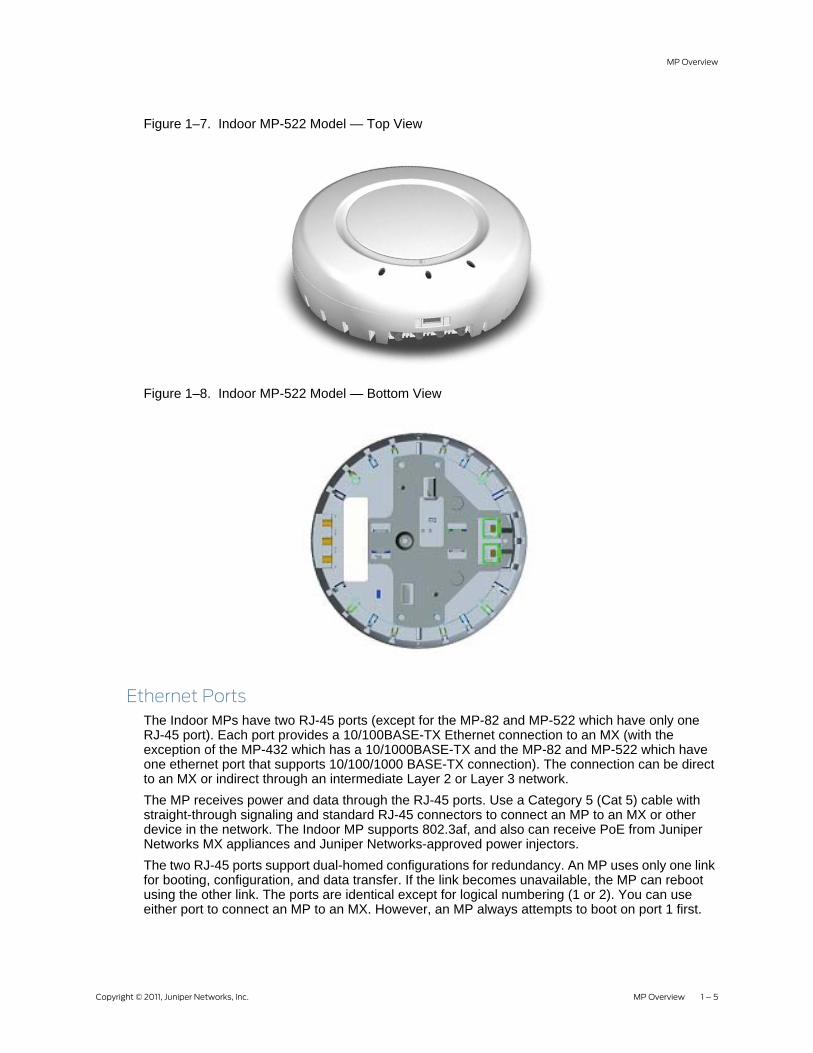
Figure 1–7. Indoor MP-522 Model — Top View
Figure 1–8. Indoor MP-522 Model — Bottom View
Ethernet PortsThe Indoor MPs have two RJ-45 ports (except for the MP-82 and MP-522 which have only one RJ-45 port). Each port provides a 10/100BASE-TX Ethernet connection to an MX (with the exception of the MP-432 which has a 10/1000BASE-TX and the MP-82 and MP-522 which have one ethernet port that supports 10/100/1000 BASE-TX connection). The connection can be direct to an MX or indirect through an intermediate Layer 2 or Layer 3 network. The MP receives power and data through the RJ-45 ports. Use a Category 5 (Cat 5) cable with straight-through signaling and standard RJ-45 connectors to connect an MP to an MX or other device in the network. The Indoor MP supports 802.3af, and also can receive PoE from Juniper Networks MX appliances and Juniper Networks-approved power injectors. The two RJ-45 ports support dual-homed configurations for redundancy. An MP uses only one link for booting, configuration, and data transfer. If the link becomes unavailable, the MP can reboot using the other link. The ports are identical except for logical numbering (1 or 2). You can use either port to connect an MP to an MX. However, an MP always attempts to boot on port 1 first.

1 – 6 MP Overview Copyright © 2011, Juniper Networks, Inc.
Only if the boot attempt on port 1 fails does the MP attempt to boot on port 2. If one port becomes unavailable, the other port can provide full power to the MP.
External Antenna Connectors The Indoor MPs (except for the MP-82, MP-432, and MP-522) have connectors for attaching optional external antennas. Table 1– 1 below lists the Juniper Networks-supported external antenna models.
Table 1– 1. Juniper Networks External Antenna Models
Model Type GainBeamwidth
Horizontal Vertical
ANT-7360802.11a 8 dBi 360° 15°
802.11b/g 6 dBi 360° 25°
ANT-7360-OUT (MP-422 only)802.11a 8 dBi 360° 15°
802.11b/g 6 dBi 360° 22°
ANT-5060 (ASTN6S) 802.11a 14.5 dBi 60° 14°
ANT-5120 (ASTN6T) 802.11a 12.5 dBi 120° 14°
ANT-5180 (ASTN6H) 802.11a 10.8 dBi 180° 14°
ANT-1060 802.11b/g 10 dBi 60° 65°
ANT-1120 802.11b/g 7 dBi 120° 60°
ANT-1180 802.11b/g 6 dBi 180° 40°
Note:
MPs do not support daisy-chain configurations. Do not connect one MP to another MP.
Note:
The numbers in parentheses in the table below are the numbers that appear on the back of an 802.11a antenna reflector plate. To verify an 802.11a external antenna model number, look for the number in parentheses
Note:
The MP-82 has three external antenna connectors, but external antennas are not supported at this time.
Note:
The Indoor MP radios are certified for use only with these external antennas.

Copyright © 2011, Juniper Networks, Inc. MP Overview 1 – 7
MP Overview
Figure 1–9 below shows some of the 802.11b/g antennas.
Figure 1–9. External 802.11b/g Antennas
The 802.11a external antennas look similar to the 802.11b/g model ANT-1180, but each has a reflector plate specific to the model number. You can identify an 802.11a external antenna model by looking on the back of the reflector plate. Do not reverse or remove the reflector plate. It is required for antenna operation. Each antenna comes with a connector cable, mounting hardware, and installation instructions.
Kensington Security SlotAll models have a slot for attachment of a Kensington security cable. The cable is not included with the MP but can be ordered separately.
!Caution
The external connectors on the MP are labeled 11B/G and 11A. Each connector is a standard SMA connector. Make sure you attach the antenna to the correct connector.
Note:
Operation in the band 5.15–5.25 GHz is restricted to indoor use only.
Model ANT-1060
Model ANT-1180
Model ANT-1120

1 – 8 MP Overview Copyright © 2011, Juniper Networks, Inc.
MP Mounting Options
You can mount an MP on any of the following types of surfaces: ❑ Suspended T-bar ceiling❑ Junction box❑ Solid surface wall or ceiling❑ Tabletop
Status LEDsThe MPs have LEDs that provide status information for the devices. Figure 1–10 below shows the locations of the LEDs. Table 1– 3 and Table 1– 3 describe the LEDs.
Figure 1–10. Health and Radio LEDs
Note:
The MP-82 is meant for ceiling and wall mounting only at this time.
Note:
The solid surface mounting option requires Cat 5 cable that does not have strain relief. The other mounting options can use Cat 5 cable with or without strain relief.
Radio 2 LEDHealth LED
Radio 1 LED
LEDs
MP-432/422/522 MP-82

Copyright © 2011, Juniper Networks, Inc. MP Overview 1 – 9
MP Overview
Table 1– 2. MP-82 LED Connectors
Indicator Color State Description
LED 1(Power/ System)
Off No power.
Amber On MP is waiting to receive boot instructions and a configuration file from an MX.
Alternating green and amber
MP is booting and receiving a configuration file from an MX. After the MP boots and receives a configuration, this alternating LED appearance persists until a radio is enabled.
Green On Powered on and ready for operation.
Management link with an MX is operational.
The MP has booted.
The MP has received a valid configuration from an MX.
At least one radio is enabled.
LED 2 (2.4G)Green Off Administratively disabled.
On 2.4GHz radio is enabled.
Blinking Unit is transmitting/receiving on 2.4GHz radio.
LED 3 (5G)Green Off Administratively disabled.
On 5GHz radio is enabled.
Blinking Unit is transmitting/receiving on 5GHz radio.
LED 4 (LAN Status)
Off No 10/100/1000 base T link detected, or administratively disabled.
Amber On Good link detected at 100Mbps.
Blinking Unit is transmitting/receiving at 100Mbps.
Green On Good link detected at 1000Mbps.
Blinking Unit is transmitting/receiving at 1000Mbps.
Table 1– 3. MP-432/422/522 LEDs
LED Appearance Meaning
Health
Solid green All the following are true:❑ Management link with an MX is operational.❑ MP has booted.❑ MP has received a valid configuration from an MX.❑ At least one radio is enabled or is in sentry mode.
Solid amber MP is waiting to receive boot instructions and a configuration file from an MX.
Alternating green and amber MP is booting and receiving a configuration file from an MX. After the MP boots and receives a configuration, this LED appearance persists until a radio is enabled or is placed in sentry mode.

1 – 10 MP Overview Copyright © 2011, Juniper Networks, Inc.
Connection OptionsYou can connect an MP access port directly to an MX port or indirectly to MX appliances through an intermediate Layer 2 or Layer 3 network. In either case, use Category 5 (CAT 5) cable with straight-through signaling for each MP connection.You also can provide data link redundancy by connecting both of the ports directly to MX ports or indirectly to MX appliances through the network.You can provide MX management redundancy even on a single MP Ethernet port by connecting the MP indirectly to multiple MX appliances through an intermediate Layer 2 or Layer 3 network.
Radio 1 Radio 2
Solid green A client is associated with the radio.
Blinking green Associated client is sending or receiving traffic.
Blinking amber Non-associated client is sending or receiving traffic.
Alternating green and amber Radio is unable to transmit. This state can occur due to any of the following:❑ Excessive radio interference in the environment is preventing
the radio from sending beacons.❑ DFS has detected radar and is restricting traffic.❑ The radio has failed.
Unlit Means one of the following:❑ Radio is disabled and active scan is enabled. (The radio is in
sentry mode.)❑ Radio is enabled, but no clients are associated with it.
Note:
Install the Cat 5 cables for the MP at the installation site before installing the MP. During installation, insert the Cat 5 cable(s) into the MP port(s) before attaching the MP to the bracket. The POE (Power Over Ethernet) and its associated LAN connections shall be interconnected only with equipment within the same building.
Note:
Operation of the MP-82 with the PowerDsine PD-7001G PoE injector is subject to Class A emissions restrictions. Please consult the Juniper Networks Regulatory Guide for more complete details and suggestions
Table 1– 3. MP-432/422/522 LEDs
LED Appearance Meaning

Copyright © 2011, Juniper Networks, Inc. Installing and Connecting an Indoor MP 2 – 1
Installing and Connecting an Indoor MP
Unpacking an MPMP-82 Package Contents
The shipping carton for an MP-82 contains the following items:1. One MP-822. Ceiling mounting kit including:
❑ One universal mounting bracket❑ Mounting template❑ screws❑ rubber feet❑ T-bar clamps
3. Installation manualBefore you begin installation:1. Open the carton and carefully remove the contents.2. Place the packing materials back in the carton and save the carton.3. Verify that you received each item in the previous list. If any item is missing or damaged,
contact Juniper Networks.
Note:
Before installing an MP, you might need to generate a Juniper Networks plan and an MP work order with RingMaster.
MP-82
Front view
Rear view
Universal Mounting Bracket
Factory attached bracket
T-bar clamps
Mounting hardware
Mounting template
Lock/ unlock tool

2 – 2 Installing and Connecting an Indoor MP Copyright © 2011, Juniper Networks, Inc.
MP-422/432/522 Package ContentsThe shipping carton for an MP contains the following items:1. One MP 2. Mounting kit including:
❑ One universal mounting bracket (attached to the MP) ❑ One paper mounting template (used for marking cutting areas and screw holes) ❑ One two-piece 14.2-millimeter (9/16-inch) T-bar clamp ❑ One two-piece 5.9-millimeter (5/8-inch) T-bar clamp❑ One two-piece 23.9-millimeter (15/16-inch) T-bar clamp❑ Two #6 sheet metal screws and two drywall anchors❑ Three adhesive rubber feet
3. One documentation pack that includes quick mounting instructions and user guide.
Figure 2–1. Shipping Carton Contents
Installation Requirements and RecommendationsFor best results, follow these requirements and recommendations before installing an MP.
RingMaster Network Plan and Work OrdersIf you are using RingMaster to plan your Juniper Networks Mobility System installation, you might want to create and verify a network plan for the entire Juniper Networks installation and generate an MP work order, before installing MPs. A network plan and the MP work orders generated from it provide the following information about MP installation and configuration:❑ Number of MPs required for adequate WLAN capacity in each coverage area❑ Detailed installation location for each MP❑ Settings for all MPs in the WLAN
T-bar clamps
Mounting template
Rubber feet Universalmounting bracket
Mounting hardware
Mobility point
840-
9502
-000
1

Copyright © 2011, Juniper Networks, Inc. Installing and Connecting an Indoor MP 2 – 3
Installing and Connecting an Indoor MP
MX RecommendationJuniper Networks recommends that you install and configure the MX before installing an MP. If the MX is already installed and configured for the MP, you can immediately verify the cable connection(s) when you plug the cable(s) into the MP .
Wall Installation RecommendationsIf you plan to install an MP on a partial wall or other vertical surface, orient the top of the MP (the side with the LEDs) toward the intended coverage area. The radio antennas transmit through the top of the MP but not through the bottom, where the bracket is located. This recommendation does not apply if you plan to use external antennas. You can orient the antennas independently of the MP. Orient an external antenna to face the intended coverage area.
MP Radio Safety AdvisoriesWhen you enable the MP radio(s) as part of MX configuration, the radios can receive and transmit radio frequency energy as soon as you connect the MP to the MX, either directly or through the network.
Radio Frequency ExposureFederal Communications Commission (FCC) Docket 96-8 for Spread Spectrum Transmitters specifies a safety standard for human exposure to radio frequency electromagnetic energy emitted by FCC-certified equipment. When used with the proper antennas (shipped in the product), Juniper Networks MPs meet the uncontrolled environmental limits found in OET-65 and ANSI C95.1-1991. Proper installation of the MP according to the instructions in this manual will result in user exposure that is below the FCC recommended limits.
Additional Radio Safety AdvisoriesFor translations of warnings, see the Juniper Networks Regulatory Guide. The guide is located at http://www.juniper.net/ and can be downloaded in PDF format.
Warning!
An Indoor MP is designed to receive power only from an 802.3af-compliant source, a Juniper Networks Mobility Exchange (MX), or a Juniper Networks-approved power injector. Connecting an MP to a Power over Ethernet (PoE) device not approved by Juniper Networks can damage the equipment.
Warning!
In the U.S., locate the MP and any externally attached antennas a minimum of 20 centimeters (7.9 inches) away from people. This safety warning conforms with FCC radio frequency exposure limits for dipole antennas such as those used in the MP.
Warning!
Do not operate the MP near unshielded blasting caps or in an otherwise explosive environment unless the device has been modified for such use by qualified personnel.
Before using a wireless device in a hazardous location, consult the local codes, national codes, and safety directors of the location for usage constraints.

2 – 4 Installing and Connecting an Indoor MP Copyright © 2011, Juniper Networks, Inc.
Cabling Requirements
Category 5 cable with straight-through signaling must be installed at the site before you install an MP. A single connection requires one cable. A dual-homed connection requires two cables.Mounting an MP on a solid surface requires Cat 5 cable that does not have strain relief. For installation on all other surfaces, you can use Cat 5 cable with or without strain relief.
Installing an Indoor Mobility PointInstallation Hardware and Tools
The table below lists the mounting hardware and tools required for each type of MP installation.
Warning!
Do not touch or move the MP when the antennas are transmitting or receiving.
Do not hold any radio device so that the antenna is very close to or touching the face, eyes, or other exposed body part while the radio antenna is transmitting.
Warning!
Do not connect or disconnect cables or otherwise work with the MP hardware during periods of lightning activity.
Note:
The MP is intended for indoor use only. Do not install the device outdoors, unless you install it with a Juniper Networks outdoor MP enclosure.
Note:
To reduce the possibility of connection interference caused by dust, clean the Cat 5 connector pins before inserting a cable into an MP.
Table 2– 1. Required Mounting Hardware and Tools
Mounting Option Required Hardware and ToolsIncluded with the Product
Suspended ceiling—flush ceiling tiles
Mounting template Yes
Universal mounting bracket Yes
T-bar clamp — A T-bar clamp is not required for a 23.9-millimeter (15/16-inch) T-bar ceiling with flush ceiling tiles.
Yes
Box cutter No
Small screwdriver (3-millimeter or 1/8-inch) No
small-pointed instrument or a paperclip No

Copyright © 2011, Juniper Networks, Inc. Installing and Connecting an Indoor MP 2 – 5
Installing and Connecting an Indoor MP
MP-82 Ceiling Mount Instructions
Suspended Ceiling Installation — Flush Ceiling Tiles MP-821. Select an installation location centered over a T-bar in the ceiling.2. Cut a hole as follows in the ceiling tile for the Cat 5 cable(s):
a. Place the mounting template over the area where you plan to install the MP.b. Use the box cutter to cut along the line marking the opening for the port connectors.c. Remove the mounting template and the material you cut from the ceiling panel.
3. Determine whether to install a T-bar clamp onto the ceiling T-bar:
Suspended ceiling—drop ceiling tiles
Mounting template Yes
Universal mounting bracket Yes
T-bar clamp Yes
Box cutter No
Small screwdriver (3-millimeter or 1/8-inch) No
small-pointed instrument or a paperclip No
Junction box
Junction box No
Two #6-32 x 1-inch machine screws Yes
Universal mounting bracket Yes
Small screwdriver (3-millimeter or 1/8-inch) No
#2 Phillips-head screwdriver No
small-pointed instrument or a paperclip No
Solid wall or ceiling
Two #6 sheet metal screws and two drywall anchors Yes
Universal mounting bracket Yes
Hammer No
Small screwdriver (3-millimeter or 1/8-inch) No
#2 Phillips-head screwdriver No
small-pointed instrument or a paperclip No
Tabletop
Universal mounting bracket Yes
Three adhesive rubber feet Yes
Small screwdriver (3-millimeter or 1/8-inch) No
small-pointed instrument or a paperclip No
Note:
Indoor MPs are UL2043 plenum rated, so it also can be installed in the space above the ceiling if preferred.
Table 2– 1. Required Mounting Hardware and Tools
Mounting Option Required Hardware and ToolsIncluded with the Product

2 – 6 Installing and Connecting an Indoor MP Copyright © 2011, Juniper Networks, Inc.
❑ If the T-bar width is 14.2 millimeter (9/16 inches), you need to install the 14.2-millimeter (9/16 inches) T-bar clamp. Go to step 4.
❑ If the T-bar width is 23.9 millimeter (15/16 inches), the universal mounting bracket fits directly onto the T-bar. Go to step 5.
4. Install the 14.2-millimeter (9/16-inch) T-bar clamp onto the ceiling T-bar as shown in Figure 2–5. a. Slide each half of the clamp onto the T-bar so that the clamp lip is fully on the T-bar. b. Slide the two halves of the clamp toward each other until the tabs are inserted completely
into the holes and the clamp fits snugly on the T-bar.
Figure 2–2. Step 4—Installing a T-bar Clamp
5. Install the universal mounting bracket as follows onto the T-bar or T-bar clamp. a. As shown in the figure below, place the universal mounting bracket against the T-bar or
clamp so that the two screw holes face downward and the two T-bar flanges face upward and are adjacent to the T-bar edges.
Figure 2–3. Step 7—Top View
b. Properly align the bracket for mounting by placing the bracket so the port connector opening is to the left of the hole you cut for the cables.
T-bar
T-bar clamp halvesSlide together
T-bar
(Viewed from above ceiling tiles, looking down.)
Universal mountingbracket
Port connectoropening

Copyright © 2011, Juniper Networks, Inc. Installing and Connecting an Indoor MP 2 – 7
Installing and Connecting an Indoor MP
c. Rotate the universal mounting bracket clockwise until the flanges snap into place on the T-bar or clamp as shown in the figure below.
Figure 2–4. Step 7—Bottom View
6. Pull the Cat 5 cable(s) about 15 centimeters (about 6 inches) out of the hole in the ceiling tile and through the port connector opening to create enough slack to insert the cable(s).
7. Insert the Cat 5 cable(s) into the connector(s):❑ For a single connection, use the connector for port 1.❑ For redundancy, insert one cable into each connector.
8. Install the Kensington lock, if you plan to use one.a. Loop the Kensington lock cable around an object that cannot be moved or damaged by a
person pulling on the cable.b. Insert the key into the Kensington lock.c. Insert the Kensington lock into the security slot on the MP.d. Rotate the key right or left to secure the lock to the MP. e. Pull on the lock to verify that it is secured to the MP.f. Remove the key.
9. Unlock the MP-82 by inserting the lock/unlock tool into the Unlock hole and push until you feel the internal bracket slide across.
10. Lift the MP into place on the universal mounting bracket as shown below.
T-bar
Universal mounting bracketPort connectoropening

2 – 8 Installing and Connecting an Indoor MP Copyright © 2011, Juniper Networks, Inc.
Make sure the cable feeds properly into the ceiling as you lift the device, and does not become trapped between the MP and the bracket.
11. Lock the MP onto the bracket by inserting the lock/unlock tool into the Lock hole on the MP and push until you feel the internal bracket slide across.
12. To ensure that the MP is fully locked onto the bracket, gently pull down on the MP and attempt to rotate it from side to side.
13. If the MP comes off the bracket, relock the device onto the bracket.14. If the MP requires an external antenna, install and connect the antenna.
MP-82 Wall Mount InstallationUse the included universal mounting bracket to wall mount the MP.1. Screw the universal mounting bracket directly to a wall.
Warning!
To prevent possible damage to the MP, make sure the device is fully locked onto the bracket before releasing it.

Copyright © 2011, Juniper Networks, Inc. Installing and Connecting an Indoor MP 2 – 9
Installing and Connecting an Indoor MP
❑ If mounting to drywall, use two screws and two wall anchors in the provided holes on the bracket that are circled in red below.
2. Connect the Ethernet cable (for power and network connection) to the port on the back of the MP-82.
3. Unlock the MP by inserting the lock/unlock tool into the Unlock hole and push until you feel the internal bracket slide across.
4. Mount the MP-82 onto the mounting bracket.5. Lock the MP onto the bracket by inserting the lock/unlock tool into the Lock hole on the MP
and push until you feel the internal bracket slide across
Installing an Indoor MP-422/432/522
Figure below shows the universal mounting bracket.
Suspended Ceiling Installation—Flush Ceiling Tiles MP-422/432/5221. Select an installation location centered over a T-bar in the ceiling.2. Cut a hole as follows in the ceiling tile for the Cat 5 cable(s):
a. Place the mounting template over the area where you plan to install the MP.b. Use the box cutter to cut along the line marking the opening for the port connectors.c. Remove the mounting template and the material you cut from the ceiling panel.
3. Determine whether to install a T-bar clamp onto the ceiling T-bar:❑ If the T-bar width is 14.2 millimeter (9/16 inches), you need to install the 14.2-millimeter (9/
16 inches) T-bar clamp. Go to step 4.❑ If the T-bar width is 23.9 millimeter (15/16 inches), the universal mounting bracket fits
directly onto the T-bar. Go to step 5. 4. Install the 14.2-millimeter (9/16-inch) T-bar clamp onto the ceiling T-bar as shown in Figure 2–
5. a. Slide each half of the clamp onto the T-bar so that the clamp lip is fully on the T-bar. b. Slide the two halves of the clamp toward each other until the tabs are inserted completely
into the holes and the clamp fits snugly on the T-bar.
Note:
Indoor MPs are UL2043 plenum rated, so it also can be installed in the space above the ceiling if preferred.

2 – 10 Installing and Connecting an Indoor MP Copyright © 2011, Juniper Networks, Inc.
Figure 2–5. Step 4—Installing a T-bar Clamp
5. Unlock the universal mounting bracket from the MP by inserting a small-pointed instrument or a paperclip into the Unlock hole on the MP as shown in Figure 2–6 below.
Figure 2–6. Step 5—Unlocking the Bracket
6. Remove the bracket as shown in Figure 2–7 below.
Figure 2–7. Step 6—Removing the Bracket
!Caution
D
Use a small-pointed instrument or a paperclip to unlock the MP. Do not use a screwdriver because it may cause damage to the MP lock mechanism or electronic components. Do not use excessive force when inserting a tool into the Unlock or Lock hole.
T-bar
T-bar clamp halvesSlide together

Copyright © 2011, Juniper Networks, Inc. Installing and Connecting an Indoor MP 2 – 11
Installing and Connecting an Indoor MP
7. Install the universal mounting bracket as follows onto the T-bar or T-bar clamp: a. As shown in Figure 2–8 below, place the universal mounting bracket against the T-bar or
clamp so that the two screw holes face downward and the two T-bar flanges face upward and are adjacent to the T-bar edges.
Figure 2–8. Step 7—Top View
b. Properly align the bracket for mounting by placing the bracket so the port connector opening is to the left of the hole you cut for the cables.
c. Rotate the universal mounting bracket clockwise until the flanges snap into place on the T-bar or clamp as shown in Figure 2–9 below.
Figure 2–9. Step 7—Bottom View
T-bar
Universal mountingbracket
Port connectoropening
T-bar
Universal mounting bracketPort connectoropening

At this point, once you have the T-bar installed and the universal mounting bracket snapped into place, you have the option of securing the bracket for earthquake safety using the two supplied M3 pen head threaded screws.Note that the T-bars and the universal mounting bracket in the MP-522 Installation Kit have two additional screw holes as shown below.
When the universal mounting bracket is snapped into place, the holes will align.Screw the two M3 pen head threaded screws into the holes. The screws will hold the T-bar and universal mounting bracket together in the event of an earthquake. The MP-522 is then locked securely into place on the secured universal mounting bracket.
M3 pan head screw
M3 pan head screw
2 – 12 Installing and Connecting an Indoor MP Copyright © 2011, Juniper Networks, Inc.
8. Pull the Cat 5 cable(s) about 15 centimeters (about 6 inches) out of the hole in the ceiling tile and through the port connector opening to create enough slack to insert the cable(s).
9. Insert the Cat 5 cable(s) into the connector(s):❑ For a single connection, use the connector for port 1.❑ For redundancy, insert one cable into each connector.
Note:
MP-522-Specific Optional Earthquake Safety Step

Copyright © 2011, Juniper Networks, Inc. Installing and Connecting an Indoor MP 2 – 13
Installing and Connecting an Indoor MP
10. Install the Kensington lock, if you plan to use one.a. Loop the Kensington lock cable around an object that cannot be moved or damaged by a
person pulling on the cable.b. Insert the key into the Kensington lock.c. Insert the Kensington lock into the security slot on the MP.d. Rotate the key right or left to secure the lock to the MP. e. Pull on the lock to verify that it is secured to the MP.f. Remove the key.
11. Lift the MP into place on the universal mounting bracket as shown in Figure 2–10 below. Make sure the cable feeds properly into the ceiling as you lift the device, and does not become trapped between the MP and the bracket.
Figure 2–10. Step 10—Placing the MP on the Bracket
12. Lock the MP onto the bracket by inserting a small-pointed instrument or a paperclip into the Lock hole on the MP as shown in Figure 2–11 below.
Warning!
To prevent possible damage to the MP, make sure the device is fully locked onto the bracket before releasing it.

2 – 14 Installing and Connecting an Indoor MP Copyright © 2011, Juniper Networks, Inc.
Figure 2–11. Step 12—Locking the Bracket
13. To ensure that the MP is fully locked onto the bracket, gently pull down on the MP and attempt to rotate it from side to side.
14. If the MP comes off the bracket, relock the device onto the bracket as described in step 12 on page 13.
15. If the MP requires an external antenna, install and connect the antenna. 16. If the other ends of the Cat 5 cable(s) are not already connected and the link activated, go to
“Connecting an MP to an MX” on page 2–28. Otherwise, go to “Verifying MP Health” on page 28.
Suspended Ceiling Installation—Drop Ceiling Tiles1. Select an installation location that is centered over a T-bar in the ceiling.2. Cut a hole as follows in the ceiling tile for the Cat 5 cable(s):
a. Place the mounting template over the area where you plan to install the MP.b. Use the box cutter to cut along the line marking the opening for the port connectors.c. Remove the mounting template and the material you cut from the ceiling panel.
3. Install the T-bar clamp that fits the T-bar: a. Slide each half of the clamp onto the T-bar so that the clamp lip is fully on the T-bar. b. Slide the two halves of the clamp toward each other until the tabs are inserted completely
into the holes and the clamp fits snugly on the T-bar.
Figure 2–12 shows an example for a 23.9-millimeter (15/16-inch) T-bar. Figure 2–13 shows an example for a 15.9-millimeter (5/8-inch) T-bar.
Figure 2–12. Step 3—Installing the T-bar Clamp for a 23.9-millimeter (15/16-inch) T-bar
Lock

Copyright © 2011, Juniper Networks, Inc. Installing and Connecting an Indoor MP 2 – 15
Installing and Connecting an Indoor MP
Figure 2–13. Step 3—Installing the T-bar Clamp for a 15.9-millimeter (5/8-inch) T-bar
4. Unlock the universal mounting bracket from the MP by inserting a small-pointed instrument or a paperclip into the Unlock hole on the MP as shown in Figure 2–14 below.
!Caution
Use the lock/unlock tool to unlock the MP. Do not use a screwdriver because it may cause damage to the MP lock mechanism or electronic components. Do not use excessive force when inserting a tool into the Unlock or Lock hole.
T-bar
T-bar clamp halvesSlide together
T-bar
T-bar clamp halvesSlide together

2 – 16 Installing and Connecting an Indoor MP Copyright © 2011, Juniper Networks, Inc.
Figure 2–14. Step 4—Unlocking the Bracket
5. Remove the bracket as shown in Figure 2–15 below.
Figure 2–15. Step 5—Removing the Bracket
6. Install the universal mounting bracket as follows onto the T-bar clamp: a. As shown in Figure 2–16, place the universal mounting bracket against the T-bar clamp so
that the two screw holes face downward and the two T-bar flanges face upward and are adjacent to the T-bar edges.
b. Properly align the bracket for mounting by placing the bracket so that the port connector opening is to the left of the hole you cut for the cables.
c. Rotate the universal mounting bracket clockwise until the flanges snap into place on the T-bar clamp as shown in Figure 2–17.

Copyright © 2011, Juniper Networks, Inc. Installing and Connecting an Indoor MP 2 – 17
Installing and Connecting an Indoor MP
Figure 2–16. Step 6—Top View
Figure 2–17. Step 6—Bottom View
7. Pull the Cat 5 cable(s) about 6 inches (about 15 centimeters) out of the hole in the ceiling tile and through the port connector opening to create enough slack to insert the cable(s).
8. Insert the Cat 5 cable(s) into the connector(s):❑ For a single connection, use the connector for port 1.❑ For redundancy, insert one cable into each connector.
9. Install the Kensington lock, if you plan to use one.a. Loop the Kensington lock cable around an object that cannot be moved or damaged by a
person pulling on the cable.b. Insert the key into the Kensington lock.c. Insert the Kensington lock into the security slot on the MP.d. Rotate the key right or left to secure the lock to the MP. e. Pull on the lock to verify that it is secured to the MP.f. Remove the key.
10. Lift the MP into place on the universal mounting bracket as shown in Figure 2–18. Make sure the cable feeds properly into the ceiling as you lift the device, and does not become trapped between the MP and the bracket.
T- bar
T-bar clamps(attachedto T-bar)
Universal mountingbracket
(Viewed from above ceiling tiles, looking down.)
Port connectoropening
T-bar
Universal mounting bracketPort connectoropening

2 – 18 Installing and Connecting an Indoor MP Copyright © 2011, Juniper Networks, Inc.
Figure 2–18. Step 9—Placing the MP on the Bracket
11. Lock the MP onto the bracket by inserting a small-pointed instrument or a paperclip into the Lock hole on the MP as shown in Figure 2–19below.
Figure 2–19. Step 10—Locking the Bracket
12. To ensure that the MP is fully locked onto the bracket, gently pull down on the MP and attempt to rotate it from side to side.
If the MP comes off the bracket, relock the device onto the bracket as described in step 11 on page 18.
13. If the MP requires an external antenna, install and connect the antenna. (See “Connecting an MP to an External Antenna” on page 2–27.)
14. If the other ends of the Cat 5 cable(s) are not already connected and the link activated, go to “Connecting an MP to an MX” on page 2–28. Otherwise, go to “Verifying MP Health” on page 28.
Warning!
To prevent possible damage to the MP, make sure the device is fully locked onto the bracket before releasing it.
Copyright © 2011, Juniper Networks, Inc. Installing and Connecting an Indoor MP 2 – 19
Installing and Connecting an Indoor MP
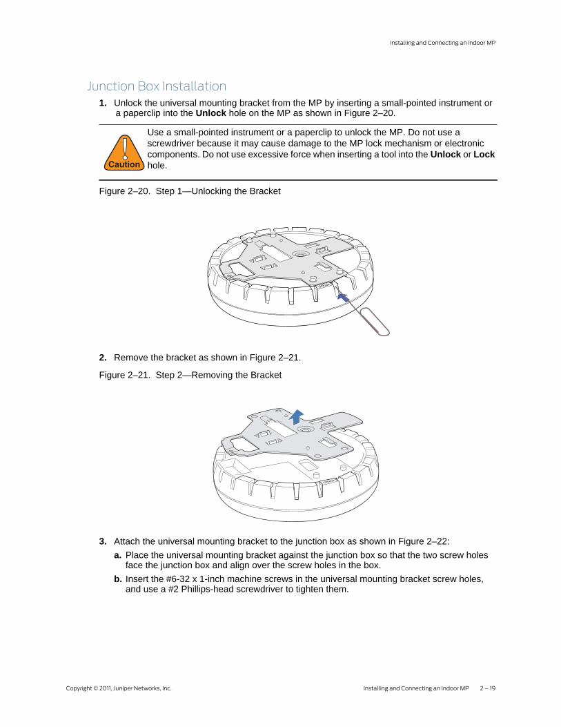
Junction Box Installation1. Unlock the universal mounting bracket from the MP by inserting a small-pointed instrument or
a paperclip into the Unlock hole on the MP as shown in Figure 2–20.
Figure 2–20. Step 1—Unlocking the Bracket
2. Remove the bracket as shown in Figure 2–21.
Figure 2–21. Step 2—Removing the Bracket
3. Attach the universal mounting bracket to the junction box as shown in Figure 2–22:a. Place the universal mounting bracket against the junction box so that the two screw holes
face the junction box and align over the screw holes in the box.b. Insert the #6-32 x 1-inch machine screws in the universal mounting bracket screw holes,
and use a #2 Phillips-head screwdriver to tighten them.
!Caution
Use a small-pointed instrument or a paperclip to unlock the MP. Do not use a screwdriver because it may cause damage to the MP lock mechanism or electronic components. Do not use excessive force when inserting a tool into the Unlock or Lock hole.

2 – 20 Installing and Connecting an Indoor MP Copyright © 2011, Juniper Networks, Inc.
Figure 2–22. Step 3—Placing the Bracket on the Junction Box
4. Pull the Cat 5 cable(s) about 15 centimeters (about 6 inches) out of the junction box and through the port connector opening to create enough slack to insert the cable(s) into the port connectors.
5. Insert the Cat 5 cable(s) into the connector(s): ❑ For a single connection, use the connector for port 1.❑ For redundancy, insert one cable into each connector. 6. Install the Kensington lock, if you plan to use one.
a. Loop the Kensington lock cable around an object that cannot be moved or damaged by a person pulling on the cable.
b. Insert the key into the Kensington lock.c. Insert the Kensington lock into the security slot on the MP.d. Rotate the key right or left to secure the lock to the MP. e. Pull on the lock to verify that it is secured to the MP.f. Remove the key.
7. Lift the MP into place on the universal mounting bracket.
Make sure the cable feeds properly into the junction box as you lift the device, and does not become trapped between the MP and the bracket.
8. Lock the MP onto the bracket by inserting a small-pointed instrument or a paperclip into the Lock hole on the MP as shown in Figure 2–23.
Warning!
To prevent possible damage to the MP, make sure the device is fully locked onto the bracket before releasing it.
Junction box
Port connectoropening

Copyright © 2011, Juniper Networks, Inc. Installing and Connecting an Indoor MP 2 – 21
Installing and Connecting an Indoor MP
Figure 2–23. Step 7—Locking the Bracket
9. To ensure that the MP is fully locked onto the bracket, gently pull down on the MP and attempt to rotate it from side to side.
If the MP comes off the bracket, relock the device onto the bracket as described in step 8.
10. If the MP requires an external antenna, install and connect the antenna. (See “Connecting an MP to an External Antenna” on page 2–27.)
11. If the other ends of the Cat 5 cable(s) are not already connected and the link activated, go to “Connecting an MP to an MX” on page 2–28. Otherwise, go to “Verifying MP Health” on page 28.
Solid Wall or Ceiling Installation
1. Prepare holes in the wall or ceiling for the universal mounting bracket, using the following steps: a. Place the paper mounting template over the location to install the MP.b. Mark the screw hole location(s).c. If you plan to route the Cat 5 cable externally along the wall or ceiling, mark the locations of
both the center screw hole and the screw hole by the port connector opening. d. If you plan to route the Cat 5 cable through a hole in the wall or ceiling, mark the location of
the center screw hole only. You cannot use the screw hole by the port connector opening if you cut a hole for the opening.
e. Remove the template.
Note:
The solid surface mounting option requires Cat 5 cable that does not have strain relief, unless you plan to route the cable through a hole in the wall or ceiling. The other options can use Cat 5 cable with or without strain relief.
Note:
Do not mark the four holes on the edges of the bracket. (These are the holes indicated by the dashed lines in Figure 2–26.) The MP fits into these holes. They are not screw holes.
Lock

2 – 22 Installing and Connecting an Indoor MP Copyright © 2011, Juniper Networks, Inc.
2. Install the drywall anchor(s):a. Hammer a drywall anchor into each hole, up to the beginning of the threads on the anchor.b. Screw each anchor the rest of the way into the hole using a #2 Phillips-head screwdriver.c. Remove the screw from each anchor and save the screw(s) for step 6.
3. Unlock the universal mounting bracket from the MP by inserting a small-pointed instrument or a paperclip into the Unlock hole on the MP as shown in Figure 2–24.
Figure 2–24. Step 3—Unlocking the Bracket
4. Remove the bracket as shown in Figure 2–25.
Figure 2–25. Step 4—Removing the Bracket
5. As shown in Figure 2–26, feed the Cat 5 cable(s) through the port connector opening and align the universal mounting bracket over the drywall anchors so that the two screw holes in the bracket face the drywall anchors.
6. Insert the #6 sheet metal screws into the screw holes, and tighten them to secure the universal mounting bracket to the wall or ceiling. (If you routed the Cat 5 cable through a hole in the wall or ceiling, insert the screw into the center screw hole only.)
!Caution
Use a small-pointed instrument or a paperclip to unlock the MP. Do not use a screwdriver because it may cause damage to the MP lock mechanism or electronic components. Do not use excessive force when inserting a tool into the Unlock or Lock hole.

Copyright © 2011, Juniper Networks, Inc. Installing and Connecting an Indoor MP 2 – 23
Installing and Connecting an Indoor MP
Figure 2–26. Steps 5 and 6—Bracket Placement on Solid Wall or Ceiling
7. Insert the Cat 5 cable(s) into the connector(s):❑ For a single connection, use the connector for port 1.❑ For redundancy, insert one cable into each connector. 8. Install the Kensington lock, if you plan to use one.
a. Loop the Kensington lock cable around an object that cannot be moved or damaged by a person pulling on the cable.
b. Insert the key into the Kensington lock.c. Insert the Kensington lock into the security slot on the MP.d. Rotate the key right or left to secure the lock to the MP. e. Pull on the lock to verify that it is secured to the MP.f. Remove the key.
9. As shown in Figure 2–27, place the MP on the bracket, making sure to remove any slack that occurs in the cable between the bracket and the MP.
Note:
Do not insert screws in the four holes on the edges of the bracket. (These are the holes indicated by the dashed lines in Figure 2–26.) The MP fits into these holes. They are not screw holes.

2 – 24 Installing and Connecting an Indoor MP Copyright © 2011, Juniper Networks, Inc.
Figure 2–27. Step 8—Cable Placement
10. Lock the MP onto the bracket by inserting a small-pointed instrument or a paperclip into the Lock hole on the MP as shown in Figure 2–28.
Figure 2–28. Step 9—Locking the Bracket
11. To ensure that the MP is fully locked onto the bracket, gently pull on the MP and attempt to rotate it from side to side.If the MP comes off the bracket, relock the device onto the bracket as described in step 10 on page 24.
12. If the MP requires an external antenna, install and connect the antenna. (See “Connecting an MP to an External Antenna” on page 2–27.)
Warning!
To prevent possible damage to the MP, make sure the device is fully locked onto the bracket before releasing it.
Universal mounting bracket
Cable
Lock

Copyright © 2011, Juniper Networks, Inc. Installing and Connecting an Indoor MP 2 – 25
Installing and Connecting an Indoor MP
13. If the other ends of the Cat 5 cable(s) are not already connected and the link activated, go to “Connecting an MP to an MX” on page 2–28. Otherwise, go to “Verifying MP Health” on page 28.
Tabletop Installation1. Reverse the universal mounting bracket:
a. Unlock the universal mounting bracket from the MP by inserting a small-pointed instrument or a paperclip into the Unlock hole on the MP as shown in Figure 2–29 below.
Figure 2–29. Step 1a—Unlocking the Bracket
b. Remove the bracket as shown in Figure 2–30 below.
Figure 2–30. Step 1b—Removing the Bracket
c. Turn over the universal mounting bracket, then align the bracket over the cable ports and the four mounting posts as shown in Figure 2–31 below.
Figure 2–31. Step 1c—Turning Over the Bracket
!Caution
Use a small-pointed instrument or a paperclip to unlock the MP. Do not use a screwdriver because it may cause damage to the MP lock mechanism or electronic components. Do not use excessive force when inserting a tool into the Unlock or Lock hole.

2 – 26 Installing and Connecting an Indoor MP Copyright © 2011, Juniper Networks, Inc.
d. Once the bracket is fully seated, lock the bracket onto the MP by inserting a small-pointed instrument or a paperclip into the Lock hole on the MP as shown in Figure 2–32 below.
Figure 2–32. Step 1d—Locking the Bracket
2. Attach the three rubber adhesive feet onto the universal mounting bracket, in the three location circles, as shown in Figure 2–33 below.
Figure 2–33. Step 2—Installing the Rubber Feet
3. Insert the Cat 5 cable(s) into the connector(s):
Lock

Copyright © 2011, Juniper Networks, Inc. Installing and Connecting an Indoor MP 2 – 27
Installing and Connecting an Indoor MP
❑ For a single connection, use the connector for port 1.❑ For redundancy, insert one cable into each connector.
4. Install the Kensington lock, if you plan to use one.a. Loop the Kensington lock cable around an object that cannot be moved or damaged by a
person pulling on the cable.b. Insert the key into the Kensington lock.c. Insert the Kensington lock into the security slot on the MP.d. Rotate the key right or left to secure the lock to the MP. e. Pull on the lock to verify that it is secured to the MP.f. Remove the key.
5. Place the MP in the desired location on the table.6. If the MP requires an external antenna, install and connect the antenna. (See “Connecting an
MP to an External Antenna” on page 2–27.)7. If the other ends of the Cat 5 cable(s) are not already connected and the link activated, go to
“Connecting an MP to an MX” on page 2–28. Otherwise, go to “Verifying MP Health” on page 28.
Connecting an MP to an External AntennaEach radio in an Indoor MP can use an optional Juniper Networks external antenna. To mount the antenna, see the instructions that come with the antenna.
To connect a mounted external antenna to an MP:1. Attach the exterior antenna cable that is shipped with the antenna to the MP external antenna
connector.Both connectors are labeled to indicate the radio type. The MP has standard SMA connectors for attachment to the 802.11b/g antenna and to the 802.11a antenna.(For the location of the external antenna connectors, see Figure 1–4 on page 3.)
2. Attach the other end of the antenna cable to the antenna.3. If the other ends of the Cat 5 cable(s) are not already connected and the link activated, see
“Connecting an MP to an MX” on page 2–28. Otherwise, go to “Verifying MP Health” on page 28.
!Caution
The external antenna must be installed at least 20 centimeters (8 inches) from the MP.
!Caution
The external connectors on the MP are labeled: 11B/G and 11A. Each connector is a standard SMA connector. Make sure you attach the antenna to the correct connector.
Note:
If the MP is installed in a Juniper Networks outdoor MP enclosure, attach the antenna cable to the lightning surge arrestor (if installed) or the SMA bulkhead connector on the enclosure.

2 – 28 Installing and Connecting an Indoor MP Copyright © 2011, Juniper Networks, Inc.
Connecting an MP to an MXYou can connect an MP directly to an MX or indirectly to the MX through an intermediate Layer 2 or Layer 3 network. If you are connecting the MP directly to an MX, use the following procedure to insert the cable into the MX and verify the link. You can use the CLI or RingMaster to configure an MP connection. If you are installing the MP as a Mesh AP in a WLAN Mesh or wireless bridge configuration, you must configure the MP connection before deploying the MP in the final location. (See the Mobility System Software Configuration Guide or the Configuration Guide.)Figure 2–34 below shows how to insert a Cat 5 cable into 10/100 Ethernet port on an MX. Refer to this figure as you perform the procedure.
Figure 2–34. 10/100 Cat 5 Cable Installation
1. Insert a Cat 5 cable with a standard RJ-45 connector as shown in Figure 2–34. For connection to an MP, use a straight-through cable.
2. When the link is activated, observe the MP LED for the port on the MX:
Verifying MP HealthAfter you install the MP and enable PoE on the Ethernet cable connected to the MP, you can easily verify the MP status by observing the LEDs, particularly the health LED. The health or LINK LED indicates if the MP is ready for operation. ❑ If the LED is green and glowing steadily, the MP has been booted successfully by the MX and
is ready for operation. ❑ If the LED is not steadily glowing green, contact the system administrator for the MX. (For more
information on MP LEDs, see Table 1– 3 on page 9 “MP Overview.”)
MP TroubleshootingAfter you insert a Cat 5 cable into an MP port connector and enable PoE on the cable, observe the device health or LINK LED to determine the status of the connection with the MX. ❑ If the LED is green and is glowing steadily, the MP has been booted successfully by the MX and
is ready for operation. ❑ If the LED is not steadily glowing green, see “Status LEDs” on page 8.)
Mobility Exchange MX-20
Ethernet cable (Cat 5 cable)
MP, switch, server or other device
Ethernet port

Copyright © 2011, Juniper Networks, Inc. MP Technical Specifications 3 – 1
MP Technical SpecificationsThis appendix lists theJ uniper Networks technical specifications for the Juniper Networks Indoor MPs. Table 3– 1 lists the mechanical and compliance specifications.
Table 3– 2, Table 3– 3, and Table 3– 4 list the radio specifications. Table 3– 5 lists the MAC address allocation scheme.(For specifications for the MX , see the Mobility Exchange Installation and Basic Configuration Guide.)
802.11 a/b/g/n Features❑ High performance 11 Mbps (802.11b) or 54Mbps (802.11a/g) or 300Mbps(802.11n) data rate ❑ Wi-Fi, WPA certificated interoperability ❑ WPA/WPA2 with PSK/802.1x with TKIP/AES❑ 40-bit and 128-bit WEP❑ Seamless roaming within the IEEE 802.11 a/b/g/n WLAN infrastructure.❑ Adjustable output power support
Note:
For detailed compliance information see the Juniper Networks Regulatory Guide. The guide is located at: http://www.juniper.net/ and can be downloaded in PDF format.
Warning!
In the U.S., locate the MP and any externally attached antennas a minimum of 7.9 inches (20 centimeters) away from people. This safety warning conforms with FCC radio frequency exposure limits for dipole antennas such as those used in the MP.
Note:
This Listed Accessory is designed and approved to be used only with Juniper Networks Mobility Exchange (MX) models MX-216, MX-20, MX-8, and MXR-2. (The MX-400, MX-2800, and MX-200s do not directly connect to the MP.)
Note:
The MP radios are disabled by default and can be enabled only by the system administrator using the RingMaster management application or the MX’s command-line interface (CLI).
Note:
The radio frequency band, operating channels, and transmit power depend on the country of operation specified by the system administrator using RingMaster or the MX CLI.

3 – 2 MP Technical Specifications Copyright © 2011, Juniper Networks, Inc.
❑ Interoperability with Juniper Networks Wireless Security Switch❑ Dual auto-sensing 10/100/1000 Ethernet port, configured as MDI.❑ Comply with IEEE 802.3, 802.3u and 802.3ab❑ Support auto MDI/MDI-X ❑ PowerDsine(Microsemi) GigE PoE injector support❑ 802.3af PoE compatability
Table 3– 1. MP Mechanical and Compliance Specifications
Specification Description
Size (MP-82) Diameter: 19.7 centimeters (7.8 inches) Height: 4.5 centimeters (1.8 inches)
Size (MP-422) Diameter: 17.14 centimeters (6.75 inches) Height: 5.71 centimeters (2.25 inches)
Size (MP-432) Diameter: 20.59 centimeters (8.11 inches) Height: 8.2 centimeters (3.23 inches )
Size (MP-522) Diameter: 17.78 centimeters (7 inches) Height: 6.35 centimeters (2.5 inches )
Weight (MP-82) Without mounting bracket: 0.99 kilograms (35.2 ounces)
Weight (MP-422) Without mounting bracket: 0.35 kilograms (12.5 ounces) With mounting bracket: 0.5 kilograms (14 ounces)
Weight (MP-432) Without mounting bracket: 0.73 kilograms (25.76 ounces)With mounting bracket: 0.82 kilograms (28.96 ounces)
Weight (MP-522) Without mounting bracket: 0.725 kilograms (25.59 ounces)With mounting bracket: 0.635 kilograms (22.39 ounces)
Operating Temperature (MP-82)
-10° C to +40° C (14° F to 122° F)
Operating Temperature (MP-422/MP-432/ MP-522)
0° C to +50° C (32° F to 122° F)
Storage Temperature (MP-82)
-40° C to +70° C (-40° F to +158° F)
Storage Temperature(MP-422/MP-432)
-20° C to +70° C (-4° F to +158° F)
Humidity 10% to 95% noncondensing
MTBF 5.7 years
RoHs/ IEEE Directive 2002/95/EC, 2006/122/ECChina RoHS
Power over Ethernet (PoE)
44 VDC to 57 VDC (48 VDC nominal)IEEE 802.3af (MP-432, MP-422, MP-341, MP-352, MP-82 and MP-522)
Status indicators Health/MX and radio LEDs(For descriptions of the LEDs, see “Status LEDs” on page 8.)
Wired network ports (MP-82/ MP-522)
Wired network ports one RJ-45 port for 10/100/1000BASE-T Ethernet and Power over Ethernet (PoE)
Wired network ports Wired network ports Two RJ-45 ports for 10/100/1000BASE-T Ethernet and Power over Ethernet (PoE)

Copyright © 2011, Juniper Networks, Inc. MP Technical Specifications 3 – 3
MP Technical Specifications
Standards compliance
IEEE 802.11IEEE 802.11aIEEE 802.11bIEEE 802.11gIEEE 802.3afIEEE 802.11eIEEE 802.11i
Safety, electromagnetic, and radio compliance
FCC Part 15, UL 60950-1CSA 22.2 N0-950, RSS-139-1 and RSS-210, CSA 60950-1ETS 300 328 (2.4 GHz) and 301 893 (5 GHz), EN 301 489-1, EN 301 489-17, EN 60601-1-2, EN 50371, EN 50392, EN 50385R&TTE Directive 1999/5/ECTELEC, ARIB T66GBT-15941-1995, GBT-16841-1997LP0002
EncryptionWi-Fi Protected Access (WPA/WPA2)Advanced Encryption Standard (AES) 40-bit/104-bit Wired-Equivalent Privacy (WEP)
GeneralPower-save mode supportedTransmit power control in 1 dBm incrementsSupports up to 250 clients per radioSupports Dynamic Frequency Selection
Table 3– 1. MP Mechanical and Compliance Specifications (continued)
Specification Description

3 – 4 MP Technical Specifications Copyright © 2011, Juniper Networks, Inc.
Table 3– 2. 802.11a/n Radio Specifications (MP-422 and MP-432)
Specification Description
Antenna typeIntegrated diversity omnidirectionalExternal Omni sectorized or directional (optional)(MP-432) Internal 3 * 3 Multiple Input Multiple Output(MIMO)
Antenna gain
Internal: 5 dBi (MP-422)Internal: 3 dBi (MP-432 and MP-82)External (Except MP-432): ❑ ANT-5060—14.5 dBi❑ ANT-5120—12.5 dBi❑ ANT-5180—10.8 dBi❑ ANT-7360—8 dBi❑ ANT-7360-OUT—8 dBi
Frequency band 5.15 GHz to 5.85 GHz based on country regulations
Operating channels Based on the country of operation specified by the system administrator
Association rates802.11n rates: MCS 0 to MCS 15802.11a rates: 54 Mbps, 48 Mbps, 36 Mbps, 24 Mbps, 18 Mbps, 12 Mbps, 9 Mbps, and 6 Mbps, with automatic fallback
Modulation Orthogonal frequency division multiplexing (OFDM)
Transmit power Based on the country of operation specified by the system administrator
Table 3– 3. 802.11b Radio Specifications (MP-373, MP422, and MP-432)
Specification Description
Antenna typeIntegrated diversity omnidirectionalExternal sectorized or directional (optional)(MP-432) Internal 3 * 3 Multiple Input Multiple Output (MIMO)
Antenna gain
Internal: 3 dBiInternal: 4 dBi (MP-432)External (Except MP-432): ❑ ANT-1060—greater than 10 dBi❑ ANT-1120—7 dBi or more ❑ ANT-1180—6 dBi or more❑ ANT-7360—6 dBi❑ ANT-7360-OUT—6 dBi
Frequency band 2.4 GHz to 2.4835 GHz based on country regulations
Operating channels Based on the country of operation specified by the system administrator
Association rates 11 Mbps, 5.5 Mbps, 2 Mbps, and 1 Mbps, with automatic fallback
Modulation Direct-sequence spread-spectrum (DSSS)
Transmit power Based on the country of operation specified by the system administrator

Table 3– 4. 802.11g/n Radio Specifications (MP-422, and MP-432)
Specification Description
Antenna typeIntegrated diversity omnidirectionalExternal sectorized or directional (optional)(MP-432) Internal 3 * 3 Multiple Input Multiple Output (MIMO)
Antenna gain
Internal: 3 dBi (Except MP-432)Internal: 4 dBi (MP-432)External (Except MP-432):
Frequency band 2.4 GHz to 2.4835 GHz based on country regulations
Operating channels Based on the country of operation specified by the system administrator
Association rates802.11n rates: MCS 0 to MCS 15802.11g rates: 54 Mbps, 48 Mbps, 36 Mbps, 24 Mbps, 18 Mbps, 12 Mbps, 9 Mbps, and 6 Mbps, with automatic fallback
Modulation Orthogonal frequency division multiplexing (OFDM)
Transmit power Based on the country of operation specified by the system administrator
Copyright © 2011, Juniper Networks, Inc. MP Technical Specifications 3 – 5
MP Technical Specifications
MAC AddressesEach MP is assigned a unique block of 64 MAC addresses. Each radio has 32 MAC addresses and can therefore support up to 32 SSIDs, with one MAC address assigned to each SSID as a BSSID.The MP MAC address block is listed on a label on the back of the MP. If the MP is already deployed and running on the network, you can display the MAC address assignments by using the show ap status command.All MAC addresses for an MP are assigned based on the base MAC address of the MP, as described in Table 3– 5 below.
❑ ANT-1060—greater than 10 dBi❑ ANT-1120—7 dBi or more ❑ ANT-1180—6 dBi or more❑ ANT-7360—6 dBi❑ ANT-7360-OUT—6 dBi
Table 3– 5. MAC Address Allocations on MPs
MP base MAC Address
❑ The MP has a base MAC address. All the other addresses are assigned based on this address.
Ethernet Port MAC Addresses
❑ Ethernet port 1 equals the MP base MAC address.❑ Ethernet port 2 equals the MP base MAC address + 1.
5Ghz Radio and SSID MAC Addresses
❑ The 5Ghz radio equals the MP base MAC address + 1.❑ The BSSIDs for the SSIDs configured on the 5Ghz radio end in odd numbers.
The first BSSID is equal to the MP’s base MAC address + 1. The next BSSID is equal to the MP’s base MAC address + 3, and so on.
2.4Ghz Radio and SSID MAC Addresses
❑ The 2.4Ghz radio equals the MP base MAC address. ❑ The BSSIDs for the SSIDs configured on the 2.4Ghz radio end in even numbers.
The first BSSID is equal to the MP base MAC address. The next BSSID is equal to the MP base MAC address + 2, and so on.

3 – 6 MP Technical Specifications Copyright © 2011, Juniper Networks, Inc.