Embed Size (px)
Citation preview

Mobility Lab User’sGuide
©2013 APDM, Inc.,
January 9, 2013
Contents
Contents1 Welcome 7
2 System Overview 8
2.1 Mobility Lab Software . . . . . . . . . . . . . . . . . . . . . . . . . . . . . . . . . . . . . . . . 8
2.2 Movement Monitors . . . . . . . . . . . . . . . . . . . . . . . . . . . . . . . . . . . . . . . . . 9
2.3 Docking Station . . . . . . . . . . . . . . . . . . . . . . . . . . . . . . . . . . . . . . . . . . . 9
2.4 Access Point . . . . . . . . . . . . . . . . . . . . . . . . . . . . . . . . . . . . . . . . . . . . . 10
3 Installing Mobility Lab 11
3.1 Windows XP USB Peripheral Behavior . . . . . . . . . . . . . . . . . . . . . . . . . . . . . . . 12
3.2 Installing 3rd Party Software . . . . . . . . . . . . . . . . . . . . . . . . . . . . . . . . . . . . 12
4 Setup 13
4.1 Hardware Setup . . . . . . . . . . . . . . . . . . . . . . . . . . . . . . . . . . . . . . . . . . . 13
4.2 Starting Mobility Lab . . . . . . . . . . . . . . . . . . . . . . . . . . . . . . . . . . . . . . . . 14
4.3 System Configuration . . . . . . . . . . . . . . . . . . . . . . . . . . . . . . . . . . . . . . . . 14
4.4 Charging . . . . . . . . . . . . . . . . . . . . . . . . . . . . . . . . . . . . . . . . . . . . . . . 15
4.5 Powering Off . . . . . . . . . . . . . . . . . . . . . . . . . . . . . . . . . . . . . . . . . . . . . 16
4.6 Re-applying your saved configuration . . . . . . . . . . . . . . . . . . . . . . . . . . . . . . . 16
5 Managing Meta-data 17
5.1 Studies . . . . . . . . . . . . . . . . . . . . . . . . . . . . . . . . . . . . . . . . . . . . . . . . 18
5.2 Subjects . . . . . . . . . . . . . . . . . . . . . . . . . . . . . . . . . . . . . . . . . . . . . . . 19
5.3 Sessions . . . . . . . . . . . . . . . . . . . . . . . . . . . . . . . . . . . . . . . . . . . . . . . 20
5.4 Trials . . . . . . . . . . . . . . . . . . . . . . . . . . . . . . . . . . . . . . . . . . . . . . . . . 21
6 Instrumenting the Subject 22
7 Testing 24
7.1 Current Selection . . . . . . . . . . . . . . . . . . . . . . . . . . . . . . . . . . . . . . . . . . 24
7.2 Selecting a Trial . . . . . . . . . . . . . . . . . . . . . . . . . . . . . . . . . . . . . . . . . . . 24
7.3 Starting the Trial . . . . . . . . . . . . . . . . . . . . . . . . . . . . . . . . . . . . . . . . . . . 25
7.4 Subject Instructions Dialog . . . . . . . . . . . . . . . . . . . . . . . . . . . . . . . . . . . . . 25
7.4.1 Back Button . . . . . . . . . . . . . . . . . . . . . . . . . . . . . . . . . . . . . . . . . 25
7.4.2 Subject Video Button . . . . . . . . . . . . . . . . . . . . . . . . . . . . . . . . . . . . 26
7.4.3 Record Button . . . . . . . . . . . . . . . . . . . . . . . . . . . . . . . . . . . . . . . . 26
7.5 The Recording Dialog . . . . . . . . . . . . . . . . . . . . . . . . . . . . . . . . . . . . . . . . 27
7.5.1 Quiescent Countdown . . . . . . . . . . . . . . . . . . . . . . . . . . . . . . . . . . . . 27
2

Contents
7.5.2 Stopping the Recording . . . . . . . . . . . . . . . . . . . . . . . . . . . . . . . . . . . 27
7.5.3 The Real-Time Data Plot . . . . . . . . . . . . . . . . . . . . . . . . . . . . . . . . . . 28
7.5.4 Latency . . . . . . . . . . . . . . . . . . . . . . . . . . . . . . . . . . . . . . . . . . . 28
7.6 Saving Trial Data . . . . . . . . . . . . . . . . . . . . . . . . . . . . . . . . . . . . . . . . . . 29
8 Remote Control 30
8.1 Supported Remotes . . . . . . . . . . . . . . . . . . . . . . . . . . . . . . . . . . . . . . . . . 30
8.2 Enabling the Remote . . . . . . . . . . . . . . . . . . . . . . . . . . . . . . . . . . . . . . . . 30
8.3 Supported Actions . . . . . . . . . . . . . . . . . . . . . . . . . . . . . . . . . . . . . . . . . . 30
9 Validating Your Data 31
10 Reporting Your Data 32
11 Exporting Your Data 33
12 The Instrumented Timed Up and Go (ITUG) Test 34
12.1 Test Environment Setup . . . . . . . . . . . . . . . . . . . . . . . . . . . . . . . . . . . . . . . 34
12.2 Subject Attire . . . . . . . . . . . . . . . . . . . . . . . . . . . . . . . . . . . . . . . . . . . . 34
12.3 Instructing the Subject . . . . . . . . . . . . . . . . . . . . . . . . . . . . . . . . . . . . . . . 35
12.4 Before Recording the Trial . . . . . . . . . . . . . . . . . . . . . . . . . . . . . . . . . . . . . 35
12.5 Recording the Trial . . . . . . . . . . . . . . . . . . . . . . . . . . . . . . . . . . . . . . . . . 35
12.6 ITUG Measure Definitions . . . . . . . . . . . . . . . . . . . . . . . . . . . . . . . . . . . . . 37
12.6.1 Timed Up And Go . . . . . . . . . . . . . . . . . . . . . . . . . . . . . . . . . . . . . . 37
12.6.2 Sit To Stand . . . . . . . . . . . . . . . . . . . . . . . . . . . . . . . . . . . . . . . . . 37
12.6.3 Gait . . . . . . . . . . . . . . . . . . . . . . . . . . . . . . . . . . . . . . . . . . . . . . 37
12.6.4 Turn . . . . . . . . . . . . . . . . . . . . . . . . . . . . . . . . . . . . . . . . . . . . . 40
12.6.5 Turn To Sit . . . . . . . . . . . . . . . . . . . . . . . . . . . . . . . . . . . . . . . . . . 40
13 The Instrumented Sway (ISway) Test 41
13.1 Test Environment Setup . . . . . . . . . . . . . . . . . . . . . . . . . . . . . . . . . . . . . . . 41
13.2 Instructing the subject . . . . . . . . . . . . . . . . . . . . . . . . . . . . . . . . . . . . . . . . 41
13.3 Before recording the trial . . . . . . . . . . . . . . . . . . . . . . . . . . . . . . . . . . . . . . 41
13.4 Recording the trial . . . . . . . . . . . . . . . . . . . . . . . . . . . . . . . . . . . . . . . . . . 42
13.5 ISway Measure Definitions . . . . . . . . . . . . . . . . . . . . . . . . . . . . . . . . . . . . . 43
13.5.1 Sway . . . . . . . . . . . . . . . . . . . . . . . . . . . . . . . . . . . . . . . . . . . . . 43
14 The Instrumented Stand and Walk (ISAW) Test 44
14.1 Test Environment Setup . . . . . . . . . . . . . . . . . . . . . . . . . . . . . . . . . . . . . . . 44
14.2 Subject Attire . . . . . . . . . . . . . . . . . . . . . . . . . . . . . . . . . . . . . . . . . . . . 44
14.3 Instructing the Subject . . . . . . . . . . . . . . . . . . . . . . . . . . . . . . . . . . . . . . . 453

Contents
14.4 Before Recording the Trial . . . . . . . . . . . . . . . . . . . . . . . . . . . . . . . . . . . . . 45
14.5 Recording the Trial . . . . . . . . . . . . . . . . . . . . . . . . . . . . . . . . . . . . . . . . . 45
14.6 ISAW Measure Definitions . . . . . . . . . . . . . . . . . . . . . . . . . . . . . . . . . . . . . 47
14.6.1 Sway . . . . . . . . . . . . . . . . . . . . . . . . . . . . . . . . . . . . . . . . . . . . . 47
14.6.2 Step Initiation (APA) . . . . . . . . . . . . . . . . . . . . . . . . . . . . . . . . . . . . . 48
14.6.3 Gait . . . . . . . . . . . . . . . . . . . . . . . . . . . . . . . . . . . . . . . . . . . . . . 48
14.6.4 Turn . . . . . . . . . . . . . . . . . . . . . . . . . . . . . . . . . . . . . . . . . . . . . 51
15 The Instrumented Long Walk (IWalk) Test 52
15.1 Test Environment Setup . . . . . . . . . . . . . . . . . . . . . . . . . . . . . . . . . . . . . . . 52
15.2 Subject Attire . . . . . . . . . . . . . . . . . . . . . . . . . . . . . . . . . . . . . . . . . . . . 52
15.3 Instructing the Subject . . . . . . . . . . . . . . . . . . . . . . . . . . . . . . . . . . . . . . . 53
15.4 Before Starting the Trial . . . . . . . . . . . . . . . . . . . . . . . . . . . . . . . . . . . . . . . 53
15.5 Recording the Trial . . . . . . . . . . . . . . . . . . . . . . . . . . . . . . . . . . . . . . . . . 53
15.6 IWalk Measure Definitions . . . . . . . . . . . . . . . . . . . . . . . . . . . . . . . . . . . . . 54
15.6.1 Gait . . . . . . . . . . . . . . . . . . . . . . . . . . . . . . . . . . . . . . . . . . . . . . 54
15.6.2 Turn . . . . . . . . . . . . . . . . . . . . . . . . . . . . . . . . . . . . . . . . . . . . . 58
16 When You Are Done 59
16.1 Docking Monitors . . . . . . . . . . . . . . . . . . . . . . . . . . . . . . . . . . . . . . . . . . 59
16.2 Power Off . . . . . . . . . . . . . . . . . . . . . . . . . . . . . . . . . . . . . . . . . . . . . . 59
17 External Synchronization and I/O 60
17.1 Configuration . . . . . . . . . . . . . . . . . . . . . . . . . . . . . . . . . . . . . . . . . . . . 61
17.2 Input Synchronization . . . . . . . . . . . . . . . . . . . . . . . . . . . . . . . . . . . . . . . . 61
17.2.1 Input Trigger Shape . . . . . . . . . . . . . . . . . . . . . . . . . . . . . . . . . . . . . 61
17.2.2 Input Trigger Level . . . . . . . . . . . . . . . . . . . . . . . . . . . . . . . . . . . . . . 61
17.2.3 Input Trigger . . . . . . . . . . . . . . . . . . . . . . . . . . . . . . . . . . . . . . . . . 62
17.2.4 Sample Selection with External Input Trigger Events . . . . . . . . . . . . . . . . . . . 62
17.2.5 Annotation of Externally Triggered Recordings . . . . . . . . . . . . . . . . . . . . . . 62
17.3 Output Synchronization . . . . . . . . . . . . . . . . . . . . . . . . . . . . . . . . . . . . . . . 62
17.3.1 Output Trigger Shape . . . . . . . . . . . . . . . . . . . . . . . . . . . . . . . . . . . . 62
17.3.2 Output Trigger Level . . . . . . . . . . . . . . . . . . . . . . . . . . . . . . . . . . . . . 63
17.3.3 Output Trigger . . . . . . . . . . . . . . . . . . . . . . . . . . . . . . . . . . . . . . . . 63
17.4 Isolated External Interface Details . . . . . . . . . . . . . . . . . . . . . . . . . . . . . . . . . 63
17.4.1 RCA Inter-AP Sync Connector . . . . . . . . . . . . . . . . . . . . . . . . . . . . . . . 64
17.4.2 6 Pin Digital Input/Output Connector . . . . . . . . . . . . . . . . . . . . . . . . . . . . 64
17.4.3 External Sync Box . . . . . . . . . . . . . . . . . . . . . . . . . . . . . . . . . . . . . . 66
17.4.4 4 Pin Analog Input/Output Connector . . . . . . . . . . . . . . . . . . . . . . . . . . . 68
4

Contents
17.4.5 Schematic . . . . . . . . . . . . . . . . . . . . . . . . . . . . . . . . . . . . . . . . . . 68
18 Firmware Updates 69
18.1 Automatic Firmware Updates . . . . . . . . . . . . . . . . . . . . . . . . . . . . . . . . . . . . 69
18.2 Manual Firmware Updates . . . . . . . . . . . . . . . . . . . . . . . . . . . . . . . . . . . . . 69
18.2.1 Flash Default Firmware . . . . . . . . . . . . . . . . . . . . . . . . . . . . . . . . . . . 69
18.2.2 Flash Alternate Firmware . . . . . . . . . . . . . . . . . . . . . . . . . . . . . . . . . . 69
18.2.3 Force Update . . . . . . . . . . . . . . . . . . . . . . . . . . . . . . . . . . . . . . . . 70
19 Calibration 71
19.1 Sensor Error Models . . . . . . . . . . . . . . . . . . . . . . . . . . . . . . . . . . . . . . . . 71
19.1.1 Accelerometers . . . . . . . . . . . . . . . . . . . . . . . . . . . . . . . . . . . . . . . 71
19.1.2 Gyroscopes . . . . . . . . . . . . . . . . . . . . . . . . . . . . . . . . . . . . . . . . . 72
19.1.3 Magnetometers . . . . . . . . . . . . . . . . . . . . . . . . . . . . . . . . . . . . . . . 73
19.1.4 Temperature . . . . . . . . . . . . . . . . . . . . . . . . . . . . . . . . . . . . . . . . . 73
19.2 Factory Calibration . . . . . . . . . . . . . . . . . . . . . . . . . . . . . . . . . . . . . . . . . 73
19.2.1 Updating Factory Calibration . . . . . . . . . . . . . . . . . . . . . . . . . . . . . . . . 74
19.3 User Calibration . . . . . . . . . . . . . . . . . . . . . . . . . . . . . . . . . . . . . . . . . . . 74
19.3.1 Magnetometer Recalibration . . . . . . . . . . . . . . . . . . . . . . . . . . . . . . . . 74
19.3.2 Gyroscope Recalibration . . . . . . . . . . . . . . . . . . . . . . . . . . . . . . . . . . 74
19.3.3 Accelerometer Recalibration . . . . . . . . . . . . . . . . . . . . . . . . . . . . . . . . 74
19.4 Clearing User Calibration . . . . . . . . . . . . . . . . . . . . . . . . . . . . . . . . . . . . . . 74
20 Working with HDF5 Files 75
20.1 HDFView . . . . . . . . . . . . . . . . . . . . . . . . . . . . . . . . . . . . . . . . . . . . . . . 75
20.2 Data Organization . . . . . . . . . . . . . . . . . . . . . . . . . . . . . . . . . . . . . . . . . . 75
20.3 File Structure . . . . . . . . . . . . . . . . . . . . . . . . . . . . . . . . . . . . . . . . . . . . 75
20.3.1 Version 3 . . . . . . . . . . . . . . . . . . . . . . . . . . . . . . . . . . . . . . . . . . . 75
20.3.2 Version 2 . . . . . . . . . . . . . . . . . . . . . . . . . . . . . . . . . . . . . . . . . . . 76
20.3.3 Version 1 . . . . . . . . . . . . . . . . . . . . . . . . . . . . . . . . . . . . . . . . . . . 78
20.4 Working with HDF 5 in MATLAB . . . . . . . . . . . . . . . . . . . . . . . . . . . . . . . . . . 79
20.5 Examples . . . . . . . . . . . . . . . . . . . . . . . . . . . . . . . . . . . . . . . . . . . . . . 79
20.6 Notes . . . . . . . . . . . . . . . . . . . . . . . . . . . . . . . . . . . . . . . . . . . . . . . . . 81
21 Monitor Reference 82
21.1 Charging . . . . . . . . . . . . . . . . . . . . . . . . . . . . . . . . . . . . . . . . . . . . . . . 82
21.2 Powering Down . . . . . . . . . . . . . . . . . . . . . . . . . . . . . . . . . . . . . . . . . . . 82
21.3 Data Storage . . . . . . . . . . . . . . . . . . . . . . . . . . . . . . . . . . . . . . . . . . . . 82
21.4 Cleaning . . . . . . . . . . . . . . . . . . . . . . . . . . . . . . . . . . . . . . . . . . . . . . . 82
5

Contents
21.5 Storage . . . . . . . . . . . . . . . . . . . . . . . . . . . . . . . . . . . . . . . . . . . . . . . 83
21.6 Drivers . . . . . . . . . . . . . . . . . . . . . . . . . . . . . . . . . . . . . . . . . . . . . . . . 83
21.7 Firmware Updates . . . . . . . . . . . . . . . . . . . . . . . . . . . . . . . . . . . . . . . . . . 83
21.8 Technical Specifications . . . . . . . . . . . . . . . . . . . . . . . . . . . . . . . . . . . . . . . 83
21.9 LED Reference . . . . . . . . . . . . . . . . . . . . . . . . . . . . . . . . . . . . . . . . . . . 84
21.9.1 Status Codes and LED Colors/Patterns . . . . . . . . . . . . . . . . . . . . . . . . . . 84
21.9.2 Movement Monitor LED Reference . . . . . . . . . . . . . . . . . . . . . . . . . . . . . 84
21.10Technical Drawing . . . . . . . . . . . . . . . . . . . . . . . . . . . . . . . . . . . . . . . . . . 87
22 Access Point Reference 88
22.1 Drivers . . . . . . . . . . . . . . . . . . . . . . . . . . . . . . . . . . . . . . . . . . . . . . . . 88
22.2 Firmware Updates . . . . . . . . . . . . . . . . . . . . . . . . . . . . . . . . . . . . . . . . . . 88
22.3 Mounting and Placement . . . . . . . . . . . . . . . . . . . . . . . . . . . . . . . . . . . . . . 88
22.4 Using Multiple Access Points . . . . . . . . . . . . . . . . . . . . . . . . . . . . . . . . . . . . 88
22.4.1 Redundancy . . . . . . . . . . . . . . . . . . . . . . . . . . . . . . . . . . . . . . . . . 88
22.4.2 Streaming from more than 6 Opals . . . . . . . . . . . . . . . . . . . . . . . . . . . . . 88
22.5 LED Reference . . . . . . . . . . . . . . . . . . . . . . . . . . . . . . . . . . . . . . . . . . . 89
22.6 Mechanical and Electrical Specifications . . . . . . . . . . . . . . . . . . . . . . . . . . . . . . 89
22.7 Technical Drawing . . . . . . . . . . . . . . . . . . . . . . . . . . . . . . . . . . . . . . . . . . 90
23 Docking Station Reference 91
23.1 Drivers . . . . . . . . . . . . . . . . . . . . . . . . . . . . . . . . . . . . . . . . . . . . . . . . 91
23.2 Power . . . . . . . . . . . . . . . . . . . . . . . . . . . . . . . . . . . . . . . . . . . . . . . . 91
23.3 Mechanical and Electrical Specifications . . . . . . . . . . . . . . . . . . . . . . . . . . . . . . 91
23.4 LED Reference . . . . . . . . . . . . . . . . . . . . . . . . . . . . . . . . . . . . . . . . . . . 92
23.5 Technical Drawing . . . . . . . . . . . . . . . . . . . . . . . . . . . . . . . . . . . . . . . . . . 93
24 Troubleshooting 94
6

1 Welcome
1 WelcomeThe Mobility Lab System is designed for the fast and easy capture of human motion within a clinical setting.
This guide will provide assistance on how to:
• Set up your hardware
• Use the Mobility Lab software to collect data
• Place the sensors on your subjects
• Upload data to the central data server
• Update your system
• Troubleshoot problems
7

2 System Overview
2 System OverviewThe Mobility Lab system allows the user to wirelessly record human movement from multiple, synchronized
monitors.
The Mobility Lab user interface
2.1 Mobility Lab Software
The Mobility Lab Software is used to configure your hardware and record your movement data. It also
provides a simple interface for entering and editing meta-data, viewing your recordings, generating reports,
and more.
• The Current Selection component of the interface provides information about the study, subject, ses-
sion, and test that is currently selected.
• The Hardware Configuration Status indicates whether the hardware has been successfully configured
for recording.
• The System Actions component of the interface provides easy access to system-wide actions such as
configuration and data upload.
• The Data Entry and Navigation component uses a tab based table to navigate, edit, and collect data.
8

2 System Overview
2.2 Movement Monitors
Movement monitors combine a number of sensors within a single package, including a 3 axis accelerometer,
a 3 axis gyro, a 3 axis magnetometer, and a temperature sensor. The accelerometers can be configured in
a high 6G mode, or a low 2G mode depending on the testing requirements. There are a number of options
for securing the monitors on subjects using a selection of straps.
2.3 Docking Station
The docking station is used to charge and configure the movement monitors. Depending on your configura-
tion, you may have up to 6 docking stations chained together into a single unit.
9

2 System Overview
2.4 Access Point
The wireless access control point (access point for short) allows for wireless communication between the
host computer and Opal movement monitors. A single access point can support up to 6 Opals.
10

3 Installing Mobility Lab
3 Installing Mobility LabMobility Lab is supported on the following platforms:
• Windows 32-bit (XP, Vista, Windows 7)
• Windows 64-bit (Vista, Windows 7)
Locate the thumb drive or CD-ROM that was shipped with your system. This drive contains the Mobility Lab
software in addition to 3rd party software that is required for automated analysis and reporting. The contents
of the drive are shown below. Open the folder the corresponds to your operating system (32- or 64-bit).
• MobilityLab UserGuide.pdf (this document)
• Win32
– MobilityLab Setup Win32.exe
– vcredist x86.exe*
– MCRInstaller Win32.exe*
– basic-miktex-2.9.3927.exe*
• Win64
– MobilityLab Setup Win64.exe
– vcredist x64.exe*
– MCRInstaller Win64.exe*
– basic-miktex-2.9.3927.exe*
(* needed for analysis and report generation)
Double click on the Mobility Lab setup file. This will guide you through most of the installation process.
Note: In Windows 8, when you launch the installer you will see a dialog indicating “Windows protected your
PC” along with a “More info” link and an “OK” button at the below. This behavior is expected. Click on the
“More info” link and select “Run anyway”.
Note: If you see a Windows User Account Control dialog asking “Do you want to allow the following program
from an unknown publisher to make changes to this computer”, select “Yes”.
Note: If you have an NEC/Renesas USB 3.0 controller, you must upgrade to the latest driver and firmware
versions, available at http://www.station-drivers.com/page/renesas.htm . Make sure to match the chipset
number you have to the firmware/driver version you are downloading. You can check this using device
manager, under the ”Universal Serial Bus Controllers” section. You will see an ”Renesas Electronics USB
3.0 Host Controller” or a ”Renesas Electronics USB 3.0 Root Hub”.11

3 Installing Mobility Lab
3.1 Windows XP USB Peripheral Behavior
Windows XP will prompt you with the “Found New Hardware” wizard every time you plug an access point
or docking station into a USB port for the first time. This happens even if you have already installed it on a
different port, and may even happen if you have already installed it on the same port. This is a “feature” of
Windows XP and not an issue in Vista or Windows 7/8. If you have a chain of multiple docking stations, you
will be prompted for each one.
When you are prompted with the “Found New Hardware” wizard:
• Select the “No, not this time” option and click “Next”
• Select the “Install the software automatically” option and click “Next”.
3.2 Installing 3rd Party Software
• Run the vcredist installer. This installs certain Microsoft tools required by the Matlab runtime.
• Run the MCRInstaller. This installs the Matlab runtime on your computer, which is needed for local
analysis and report generation. Note: If you receive an error at the end of the installation indicating
“Error 1904. Module ...\mwcommgr.dll failed to register”, you may have to reboot your computer and
start the MCRInstaller again.
• Run the MikTex installer. When prompted:
– Specity that it be a shared installation (all users)
– Use the default installation directory
– Choose “Letter” as the preferred paper size
– Select “Yes” for “Install missing packages on-the-fly”
12

4 Setup
4 Setup
4.1 Hardware Setup
1. Plug in the Mobility Lab computer and turn it on. Wait for it to fully start up.
2. Grab a USB cable with a type-B (large, boxy) connector and plug it into the access point.
3. Plug the access point into an your computer (the computer in your kit may be a different model than the
one pictured in the figure). You should see the light on the access point turn solid green.
4. If multiple docking stations are chained together, you must plug the external power adapter into the
docking station. You should see the the lights on each docking station turn yellow when power is
applied.
5. Grab a USB cable with a micro (small, flat) connector and plug it into your docking station. If you are
using a USB hub, make sure that it is a USB 2.0 High Speed hub and that it has external power. The
LEDs on the docking station(s) should turn to solid green when they are recognized by the computer.
13

4 Setup
6. Dock the movement monitors into their docking stations. You should see the light on the monitors turn
dark blue.
4.2 Starting Mobility Lab
1. To start Mobility Lab, double-click on the “Mobility Lab” shortcut on the computer’s desktop, task bar, or
start menu.
4.3 System Configuration
1. Click on the “Setup” tab to view your configuration options
a) Body Site: Check the boxes next to the body sites you with to record from.
b) Monitor IDs: For each body site you are recording from, you must specify the ID of the monitor
you will place on that location. The monitor ID is a unique number found on the back of each
monitor. For body sites with left/right options (e.g., Legs), you must specify a monitor for both the
left and right.
c) Measures: Recording from different body sites enables the calculation of different movement
measures. This column displays the measures that correspond to each body site and the test
type(s) that provide these measures.
d) Wireless Channel: Monitors transmit data in the 2.4 ghz wireless spectrum range. Channel zero
corresponds to roughly 2.40 ghz, and channel 90 corresponds to roughly 2.49 ghz. Many other
consumer electronic devices make use of radio frequencies in the 2.4 ghz spectrum, such as
14

4 Setup
The Setup Tab
WiFi routers, cordless phones, and blue-tooth devices. Because of this, it’s important to choose a
channel that is not heavily in use by another device or you may experience wireless issues. The
default channel for Mobility Lab is 90, because it is typically out of the range of most WiFi routers.
If you experience wireless issues, the most common source of interference is from WiFi routers.
You can determine the channel that your WiFi router is running on and determine its corresponding
frequency from the following URL: http://en.wikipedia.org/wiki/IEEE_802.11.
e) Enable Remote: Mobility Lab supports an external remote for navigating a recording session. See
Section 8 for details.
2. Once you are done choosing your configuration options, click the “New Configuration” button in the
Configuration panel on the left side of the screen. This will create a new configuration and save it for
future use. The status panel on the left of the screen should indicate “Ready”.
3. If you get an error indicating that the wrong monitors are docked, make sure the monitor IDs that are
entered in the left column match those that are etched onto the back of the monitor cases.
4. After successful configuration, undock the monitors. In a few moments (∼10 seconds), they should
start blinking green in unison, indicating that they are synchronized. The access point should also start
blinking green at this time, indicating a good wireless signal has been established.
4.4 Charging
The monitor’s batteries will charge whenever they are docked and the power supply is attached to the docking
station. It is not necessary to have the computer on or the USB cable attached to charge the monitors. If
they configuration status of the system is “Ready”, and the monitors have not been powered off (see the next
item), the monitors will turn on and will be ready for more recording when they are undocked.
15

4 Setup
4.5 Powering Off
If the monitors are fully charged or you want to store them overnight or for a longer duration, you can power
them off. To do so, dock the monitors you want to power off and click on the “Power Off” button. They will
remain charging as long as they are docked, but will power off the next time they are undocked.
4.6 Re-applying your saved configuration
If you power off your monitors, reboot or put your PC to sleep, or unplug the access point, you will have
to re-apply your saved configuration before recording. This process happens automatically when Mobility
Lab is started up, and you will be prompted to plug in all of your hardware before the configuration is re-
applied. If your monitors are already powered on, it is not necessary to have them docked when re-applying
the configuration. This is useful, for example, if you already have a subject instrumented with a number of
monitors and your PC reboots or the access point is accidentally unplugged.
16

5 Managing Meta-data
5 Managing Meta-dataMobility Lab provides a simple interface for associating clinical and demographic meta-data with your record-
ings. The user interface is intended for multi-subject studies, and has a minimal design that is optimized for
ease of use in order to minimize training time.
Meta-data captured by Mobility Lab is organized hierarchically using the following structure:
Study (1 or more)
• Study description
• Subjects (1 or more)
– Subject Public ID
– Is the subject a control?
– Sessions (1 or more)
* Trials (1 or more)
· Test type
· Condition
· Notes
· Status
· Date
· File name of recording
This structure is mirrored in the tab bar, which can be used to navigate and edit this meta-data hierarchy.
Mobility Lab does not have any fields that are considered protected health information (PHI), simplifying the
security safeguards that need to be implemented.
Entry of data is kept at a minimum, while providing enough meta-data for your recordings to facilitate down-
stream analysis.
17

5 Managing Meta-data
5.1 Studies
• Studies are the highest level data structure in Mobility Lab, and provide a mechanism for grouping
together collections of subjects.
• Click on the “Add Study” button to add a new study. Any number of studies can be created.
• Studies must each have a unique name.
• The study name and description can be edited by selecting the desired study in the “Studies” table and
clicking on the “Edit Study” button on the bottom of the screen.
• To view the subjects associated with a specific study (drill-down), you can either:
– Select (single-click) the study in the table, then click on the “Subjects” tab
– Double-click on the study in the table.
18

5 Managing Meta-data
5.2 Subjects
• Subjects correspond to unique human participants in the study.
• Click on the “Add Subject” button to add a new subject. Any number of subject can be created.
• Only the Public ID is required to be entered.
• Subjects must each have a unique Public ID within a given study. Identical Public IDs can be used in
different studies to refer to either the same or different human participants.
• The subject Public ID, control value, and year of birth can be edited by selecting the desired subject in
the “Subjects” table and clicking on the “Edit Subject” button on the bottom of the screen.
• To view the sessions associated with a specific study (drill-down), you can either:
– Select (single-click) the subject in the table, then click on the “Sessions” tab
– Double-click on the subject in the table.
19

5 Managing Meta-data
5.3 Sessions
• Sessions are defined as a collection of trials that a subject performs. This collection is typically specified
by the study protocol.
• Click on the “Add Session” button to add a new session. Any number of sessions can be created.
• The session notes can be edited by selecting the desired session in the “Sessions” table and clicking
on the “Edit Session” button on the bottom of the screen.
• You can generate session level reports of the session’s trials by selecting (single-clicking) a session
from the table, and clicking on the “Generate Report” button. This button will be disabled if there are no
recorded trials for the session.
• The current status of the session (Not Started, Incomplete, or Complete) is indicated in the last column
of the table. It is considered complete when all of the session’s trials have been completed.
• To view the trials associated with a specific session (drill-down), you can either:
– Select (single-click) the session in the table, then click on the “Trials” tab
– Double-click on the session in the table.
20
5 Managing Meta-data
5.4 Trials
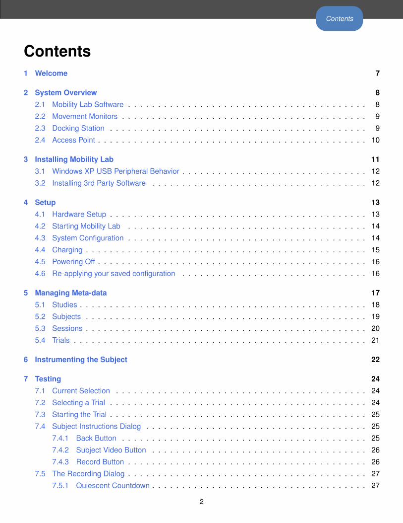
• Trials represent the recording of a specific test. For example, a single session may include 3 TUG trials
and 3 Sway trials.
• To start a trial, click on the “Start Trial” button. See Section 7 for more information.
• The trial notes can be edited by selecting the desired traial in the “Trials” table and clicking on the “Edit
Trial” button on the bottom of the screen.
• You can generate a raw data view by selecting (single-clicking) a trial from the table, and clicking on the
“Plot Data” button. This button will be disabled if the trial has not yet been recorded.
• You can generate trial level reports by selecting (single-clicking) a trial from the table, and clicking on
the “Generate Report” button. This button will be disabled if the trial has not yet been recorded.
• The current status of the trial (Not Started or Recorded) is indicated in the last column of the table.
21

6 Instrumenting the Subject
6 Instrumenting the SubjectTesting requires 6 different sensors to be placed on the subject:
• Left and right wrists (monitors with velcro strap attachments)
• Left and right ankles (monitors with velcro strap attachments)
• Trunk (monitor with the chest holster)
• Lumbar (monitor with the elastic belt attachment)
22

6 Instrumenting the Subject
Use the following visual guide and written tips for instrumenting the subject with the monitors:
• Before placing the monitors on the subject, check to make sure that:
– The “System Status” indicator on the left panel in Mobility Lab says “Ready”
– The LED on the access point is blinking green, indicating a good wireless signal.
– The LEDs on the monitors are all blinking green in unison, indicating that they are synchronized.
• As a rule of thumb, the LED on each monitor should be oriented in the top left corner after it is placed
on the subject. For the wrist monitors, this should hold true when the subjects arms are down at their
side.
• The wrist monitors should be worn on the top of the wrist and underneath any clothing, as a wrist watch
would be.
• The ankle monitors should be worn on the front of the ankles and underneath any clothing.
• The shoulder harness and belt can be worn over clothing.
23

7 Testing
7 TestingTesting is the process of:
1. Selecting a trial to complete
2. Providing instruction to the subject, such that the test can be completed in specific way
3. Recording the trial
7.1 Current Selection
The current selection is always displayed in the upper left panel.
By default, the first incomplete trial from the first subject in the first study is selected. You can use the tabs at
the top of the Mobility Lab interface to navigate the different levels of this selection.
7.2 Selecting a Trial
In order to change the current selection, start by pressing the study tab in the Mobility Lab workspace.
Double-click on the active study to drill-down to the list of subjects for the study. Repeat this process to select
the desired selection and trial. Use the “Add” button at any level to create a new subject, session, etc. See
Section 5 for more information on managing study meta-data.
24
7 Testing
7.3 Starting the Trial
Once you have selected the trial you wish to record, either double-click on it, or press the “Start Trial” button
to continue.
7.4 Subject Instructions Dialog
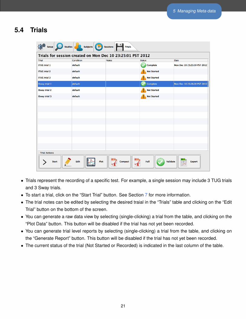
After starting the trial, the subject instructions dialog will first be presented. These are not typically the full set
of instructions for the subject, but rather some key reminders that could be read aloud to the subject before
each trial.
Along the bottom of the subject instructions dialog, there are three buttons: “Back”, “Subject Video”, and
“Record”.
7.4.1 Back Button
The “Back” button will cancel the recording of the trial and will take you back to the “Trials” table in Mobility
Lab.
25

7 Testing
7.4.2 Subject Video Button
The “Subject Video” button will play a short video for the subject to watch. This video should be viewed
before the first trial is performed, and can be repeated for additional trials if it is believed the subject needs
additional instruction.
Note: not all test types will have video instruction available. If a specific test does not have video available,
then the “Subject Video” button will not become enabled.
7.4.3 Record Button
When the subject instruction dialog is first opened, the system is working in the background to prepare for
recording. Because of this, the “Record” button does not become enabled right away. After it has become
enabled (this typically takes less than 10 seconds), clicking on the “Record” button will start the trial by
opening the recording dialog and initiating the recording of data.
26
7 Testing
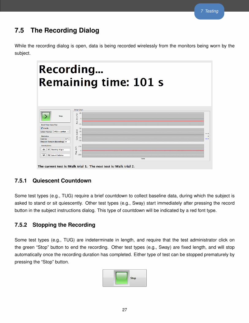
7.5 The Recording Dialog
While the recording dialog is open, data is being recorded wirelessly from the monitors being worn by the
subject.
7.5.1 Quiescent Countdown
Some test types (e.g., TUG) require a brief countdown to collect baseline data, during which the subject is
asked to stand or sit quiescently. Other test types (e.g., Sway) start immediately after pressing the record
button in the subject instructions dialog. This type of countdown will be indicated by a red font type.
7.5.2 Stopping the Recording
Some test types (e.g., TUG) are indeterminate in length, and require that the test administrator click on
the green “Stop” button to end the recording. Other test types (e.g., Sway) are fixed length, and will stop
automatically once the recording duration has completed. Either type of test can be stopped prematurely by
pressing the “Stop” button.
27

7 Testing
7.5.3 The Real-Time Data Plot
The real-time data plot provides a view of the raw data as it is being recorded. This can provide a visual
indication that the data is being collected as expected. For tests that require multiple monitors, you can use
the “Select Monitor” combo box to choose among the various monitors in your setup.
7.5.4 Latency
Typical latency for the wireless streaming of data is between 0.2-0.4 s. It is possible, however, that the latency
may increase beyond this value. Some cases where this may occur are:
• Crowded wireless spectrum. The 2.4 GHz spectrum that the Mobility Lab system uses for wireless
transmission is also used by numerous other consumer and industrial electronic devices such as cord-
less phones, computer WiFi networks, and Bluetooth devices.
• Poor wireless signal. It is recommended that there is clear line-of-sight between the access point and
the instrumented subjects. The face of the access point should be pointing, as much as possible,
towards the area the subject will occupy during testing.
• Obstruction. Sometimes, one or more monitors will become obstructed during the trial. For example,
this may happen while the subject crosses their arms during a Sway test, or the back of a chair may
block the signal from a monitor work on the lumbar region.
In most cases, some additional latency will not be a problem. The data is buffered to the monitors while
recording, and will stream wirelessly once the obstruction has been removed. It is, however, important
to have a clean signal at the time the system is preparing for recording. This happens when the subject
instruction dialog is first opened and before the “Record” button is enabled. It is important during this time to
have the access point directed at the subject, and to have all of the monitors unobstructed.
28

7 Testing
7.6 Saving Trial Data
After a trial has ended (either automatically for fixed duration recordings or by pushing the “Stop” button), you
will be presented with the confirmation dialog.
In this dialog, you can:
• Add notes that may be relevant for future analysis of the raw data. These notes can also be added or
edited from the “Trials” table in Mobility Lab.
• Redo the trial you just recorded.
• Discard the trial you just recorded and return to the “Trials” tab in Mobility Lab.
• Validate the trial you just recorded. For more information about validation, see Section 9.
• Keep the trial you just recorded and return to the “Trials” tab in Mobility Lab.
• Keep the trial that you just recorded and continue to the next trial. This option is not available for the
last trial of the session.
• Validate the entire session and return to the “Trials” tab in Mobility Lab. This option is available for the
last trial of the session.
29

8 Remote Control
8 Remote ControlMobility Lab supports the use of a remote control to aid while collecting data. This functionality makes it
possible for a single attendant to collect all of a session’s data while following and possibly assisting the
subject.
8.1 Supported Remotes
Mobility Lab has been designed to use a standard presentation remote intended for navigating a slide pre-
sentation. Our preferred remote is the Logitech R400, but other presentation remotes will most likely work
out of the box because the buttons are typically standardized.
8.2 Enabling the Remote
Enabling and disabling the remote can be performed in both the configuration tab and in the Subject In-
structions screen prior to recording a trial. When the remote is enabled, on-screen buttons that are mapped
to remote functionality will have their standard icons either overlayed or replaced by special remote icons.
These icons are modeled after those on the Logitech R400 remote to make the mapping clear.
Examples of Mobility Lab button icons that map to remote control buttons
8.3 Supported Actions
The remote functionality is available on the following screens:
• The Trials tab (can be used to start the selected trial)
• The Subject Instruction screen (can be used to show the instructional video, cancel recording the trial,
or start the recording)
• The Trial Confirmation dialog (can be used to redo the trial, go to the next trial, or exit back to the Trials
tab with or without keeping the trial just recorded)
30

9 Validating Your Data
9 Validating Your DataMobility Lab’s validation functionality enables you to determine which, if any, of your collected data is prob-
lematic for the analysis routines. This may be true if the data collected from a particular trial is aberrant and
may be caused by:
• Placing the monitors incorrectly or on the wrong part of the body
• The subject did not follow instructions
• The subject had an event (e.g., a fall) during the trial
• The behavior of the subject during a trial was out of bounds (e.g., runs during the ITUG test instead of
walks)
• A technical problem while recording
Other details about validation include:
• When you press the validate button, whatever is selected in the current tab is chosen for validation.
Your data can be validated at any level: a single trial, a session, a subject, or an entire study.
• Trials will be labeled as either valid or invalid after the validation routine completes.
• A dialog will pop up if any trials fail validation. These files will be indicated.
• Validating the data provides an error message will provide information about the nature of invalid trials.
The Validate button
31
10 Reporting Your Data
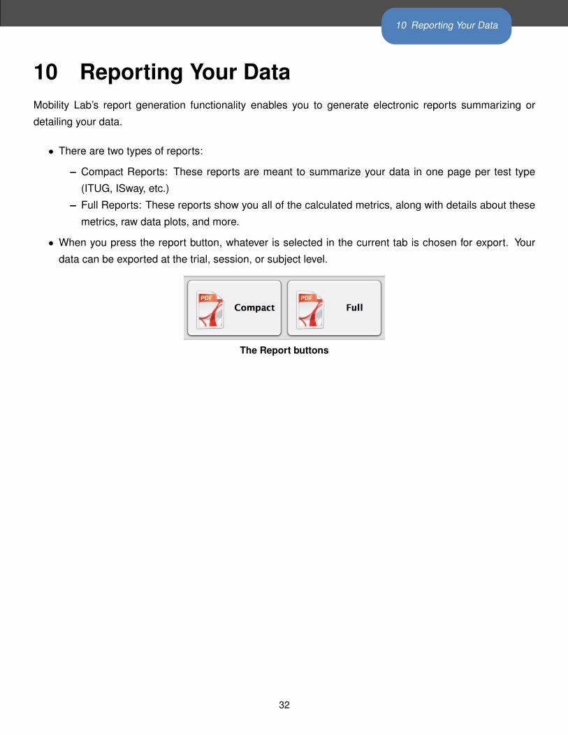
10 Reporting Your DataMobility Lab’s report generation functionality enables you to generate electronic reports summarizing or
detailing your data.
• There are two types of reports:
– Compact Reports: These reports are meant to summarize your data in one page per test type
(ITUG, ISway, etc.)
– Full Reports: These reports show you all of the calculated metrics, along with details about these
metrics, raw data plots, and more.
• When you press the report button, whatever is selected in the current tab is chosen for export. Your
data can be exported at the trial, session, or subject level.
The Report buttons
32

11 Exporting Your Data
11 Exporting Your DataMobility Lab’s export functionality enables you to export your study’s metadata, analysis results, and even
raw sensor data into a format for further analysis.
• When you press the export button, whatever is selected in the current tab is chosen for export. Your
data can be exported at any level: a single trial, a session, a subject, or an entire study.
• The metadata and analysis results are exported using the comma separated value (CSV) format. This
format can easily be read by 3rd party analysis software such as Excel and Matlab.
• If desired, all of the raw data can be exported as well. See Section 20 for details on how to work with
the raw sensor data.
• The exported data is archived in the zip format, which is supported natively by windows (e.g., you don’t
need 3rd party zip software).
• Each test type (ITUG, ISway, etc.) has its own CSV file within the archive. All raw data is put into a
separate folder within the archive.
The Export button
33

12 The Instrumented Timed Up and Go (ITUG) Test
12 The Instrumented Timed Up and Go (ITUG)Test
12.1 Test Environment Setup
• Measure a 7 meter walkway, with significant space on either side
• Mark the start and finish of the walkway with colored tape on the floor
• Place a chair without arms or swivel at the start of the walkway, just behind the marked tape.
• Ensure that the computer screen is out of the subject’s line of sight during testing.
12.2 Subject Attire
• The subject should wear clothing that does not bind or impede their movement in any significant way.
• The subject should wear comfortable walking shoes (i.e., no high-heels or flip-flops). If the subject does
not have appropriate shoes, please have them walk barefoot (no socks) and MAKE A NOTE in the
comments section of either the session or each TUG trial.
Before clicking on the “Start Trial” button, make sure that:
• The LED on the access point is blinking green, indicating a good wireless signal.
If the access point is blinking red or green-red, you may not have a good wireless signal or one of the monitors
may be obstructed. For example, it is possible that the chair being used is blocking the wireless signal from
the lumbar monitor. If this is true, get a different chair that has an open lower back area and/or reposition the
access point to get a better signal.34

12 The Instrumented Timed Up and Go (ITUG) Test
12.3 Instructing the Subject
After clicking on the “Start Trial” button in Mobility Lab, you will be presented with the subject instruction
dialog and the following written instructions:
• “When I say ‘Walk’, stand up from the chair, walk to the line, turn around, walk back, and sit down.
After you sit back down, sit quietly until you hear the tone or are told the test is complete. Walk at
a natural and comfortable pace, looking straight ahead. Try not to use your hands to assist yourself
during standing or sitting.”
Note: If the subject is unable to go from sit-stand in a safe manner, they should use their hands, but a NOTE
in the comments section should be made.
The first time the subject takes the test, they should view the video instructions by clicking on the “Subject
Video” button.
12.4 Before Recording the Trial
Prior to recording the trial, verify that the subject:
• is relaxed
• has his/her back is against the chair
• has his/her feet are on the ground behind the start line.
• has his/her hands are in their lap
12.5 Recording the Trial
• To begin recording, press the “Record” button or press the enter key.
• The time counter will start counting downwards on the record dialog (3..2..1..) as the baseline data is
collected. Please ensure that the patient is motionless during this time.
• When the countdown is complete, the test administrator should say “Walk”.35

12 The Instrumented Timed Up and Go (ITUG) Test
• During the test the examiner should be “Spotting” the patient as needed (for safety) by walking slightly
to the side and behind the subject so as not to affect their pace.
• When the patient has returned and is sitting with his/her back against the chair, press the “Stop button.
• The system will continue collecting data for 3 seconds. Please ensure that the patient is motionless
during this time.
• The computer will then confirm that the trial has ended by closing the testing window and displaying the
confirmation dialog. Here, you can enter any notes about the recording, if necessary. Choose to either
keep or discard the recording.
• If a subject error occurs during the trial, such as:
– Incompletion of the course.
– The subject uses his/her hands during sit-stand or stand-sitnot due to necessity.
– The subject does not fully cross the line.
– The subject makes an incorrect turn (goes around the line, instead of across).
• The examiner can press the “Stop button, stopping the trial in the middle of testing. The examiner
should then inform the subject of the error and how to correct it. If it is believed that the subject can
complete the trial successfully, then the trial should be re-done.
• The subject instructions visible in the dialog box should be read aloud to the subject on each subsequent
TUG trial (within reason) to ensure that the proper behavior is enforced for each trial.
36

12 The Instrumented Timed Up and Go (ITUG) Test
12.6 ITUG Measure Definitions
The ITUG analysis algorithms automatically processes recorded movement data and provide objective mea-
sures related to four major components of the tests: turning, gait, sit-to-stand and turn-to-sit.
The primary outcomes in each table are highlighted by bold text. These measures might be of primary
interest for clinical applications. Researchers might be interested in both primary and secondary outcomes.
12.6.1 Timed Up And Go
The total time of the timed up and go test is calculated in one of two ways:
1. If the trunk sensor is present and the sit-to-stand and turn-to-sit events are both detected, the total test
time is defined as the period between the initiation of sitting up to the termination of sitting back down.
2. If the sit-to-stand and turn-to-sit events are not detected, the total test time is defined as the period be-
tween the pressing of the record button and the stop button. The 3-second rest period at the beginning
and end of the test are subtracted from this total.
Measure Unit Description
Total Time Time (seconds) The total time of the timed up and go test.
12.6.2 Sit To Stand
Sit-to-Stand transition is detected and assessed using the signals from the trunk sensor [5].
Measures Unit Sensors Description
SiSt Duration Time (seconds) Trunk Duration of sit-to-stand. Measured according to the mathematical
model of sit-to-stand transition.
Peak SiSt Velocity Degrees / second Trunk Peak (95%) angular velocity of trunk in the sagittal plane during
sit-to-stand transition.
RoM Trunk Degrees Trunk RoM of trunk in the sagittal plane during sit-to-stand transition.
12.6.3 Gait
Gyroscopes attached on the shanks are used to detect the basic gait events, i.e. time feet hit the ground
and leave the ground (initial and terminal contacts). Temporal gait measures are then calculated based on
the time of gait events. In the next step, ranges of motions (RoM) of the shank segments are estimated
by integrating the gyroscopes signals. Finally, spatial gait measures are estimated using a biomechanical
model [6]. Gait measures are reported for individual gait cycles in the CSV export. A gait cycle is defined as
37

12 The Instrumented Timed Up and Go (ITUG) Test
the period between two consecutive initial contacts (heel-strike) of the right foot.
Spatial gait measures
Measures Unit Sensors Description
Stride Length % of Subjects body
height*
Shanks Distance between two consecutive foot falls at the moments of ini-
tial contacts. Averaged for left and right side. The value is normal-
ized for height.
Stride Length R % of Subjects
height*
Shanks Distance between two consecutive right foot falls at the moments
of initial contacts
Stride Length L % of Subjects
height*
Shanks Distance between two consecutive left foot falls at the moments of
initial contacts
Stride Velocity % of Subjects
height / second*
Shanks Walking speed. Average of the right and left sides.
Stride Velocity R % of Subjects
height / second*
Shanks Walking speed of right leg
Stride Velocity L % of Subjects
height / second*
Shanks Walking speed of left leg
*Values are given relative to the subject’s body height to enable comparison to normative data. If the subject’s
height is entered through Mobility Lab, then values will additionally be provided in units of meters.
Temporal gait measures
Measures Unit Sensors Description
Cadence Steps / minute Shanks Stepping rate
Gait Cycle Time Time (seconds) Shanks Duration of a complete gait cycle
Double Support % of GCT Shanks Percentage of a gait cycle that both feet are on the ground
Swing % of GCT Shanks Average percentage of a gait cycle that either foot is off the ground
Swing R % of GCT Shanks Percentage of a gait cycle that right foot is off the ground
Swing L % of GCT Shanks Percentage of a gait cycle that left foot is off the ground
Stance % of GCT Shanks Average percentage of a gait cycle that either foot is on the ground
Stance R % of GCT Shanks Percentage of a gait cycle that right foot is on the ground
Stance L % of GCT Shanks Percentage of a gait cycle that left foot is on the ground
Initial Contact R Time (seconds) Shanks The time (relative to the beginning of the trial) that right foot hits
the ground. Sometimes referred to as heel-strike.
Terminal Contact L Time (seconds) Shanks The time (relative to the beginning of the trial) that right foot leaves
the ground. Sometimes referred to as toe-off.
Initial Contact L Time (seconds) Shanks The time (relative to the beginning of the trial) that left foot hits the
ground.
Terminal Contact L Time (seconds) Shanks The time (relative to the beginning of the trial) that left foot leaves
the ground.
38

12 The Instrumented Timed Up and Go (ITUG) Test
Ranges of motions (RoM) and angular velocities
Measures Unit Sensors Description
Shank RoM Degrees Shanks RoM of shanks; averaged of the left and right sides.
RoM Shank R Degrees Shanks RoM of right shank.
RoM Shank L Degrees Shanks RoM of left shank.
Peak Shank
Velocity
Degrees / seconds Shanks Peak (95%) angular velocity of shanks. Average of the left and
right sides.
Peak Shank
Velocity R
Degrees / seconds Shanks Peak (95%) angular velocity of right shank.
Peak Shank
Velocity L
Degrees / seconds Shanks Peak (95%) angular velocity of left shank.
Peak Arm Velocity Degrees / second Shanks +
Arms
Peak (95%) angular velocity of arms. Average of the left and right
sides.
Peak Arm Velocity
R
Degrees/ second Shanks +
Arms
Peak (95%) angular velocity of right arm. Measured as the norm
of 3D angular velocity vector.
Peak Arm Velocity L Degrees/ second Shanks +
Arms
Peak (95%) angular velocity of left arm. Measured as the norm of
3D angular velocity vector.
Arm-Swing
Velocity
Asymmetry
% Shanks +
Arms
Asymmetry of left/right arm-swing angular velocity. Defined as the
difference between the two sides as percentage of the fastest side.
Arm RoM Degrees Shanks +
Arms
RoM of arms during arm-swing. Average of the left and right sides.
RoM Arm R Degrees Shanks +
Arms
RoM of right Arm. Measures as the norm of 3D arm rotation vector.
RoM Arm L Degrees Shanks +
Arms
RoM of right Arm. Measures as the norm of 3D arm rotation vector.
Trunk Sagittal RoM Degrees Shanks +
Trunk
RoM of trunk in sagittal plane.
Trunk Horizontal
RoM
Degrees Shanks +
Trunk
RoM of trunk in horizontal plane.
Trunk Sagittal
Peak Velocity
Degrees /second Shanks +
Trunk
Peak angular velocity of trunk in sagittal plane.
Trunk Horizontal
Peak Velocity
Degrees / second Shanks +
Trunk
Peak angular velocity of trunk in horizontal plane.
39

12 The Instrumented Timed Up and Go (ITUG) Test
12.6.4 Turn
Turning is detected and assessed based using gyroscopes within the trunk or lumbar sensor. A mathematical
model is used to detect the exact moment of beginning and end of turning [4].
Measures Unit Sensors Description
Turning Duration Time (seconds) Trunk Duration of 180 turn. Measured according to the mathematical
model of turning.
Number of Steps Number Shanks +
Trunk
Number of steps during 180 turn. Steps which are at least 50%
within turning period are counted.
Peak Turning
Velocity
Degrees / second Trunk Peak (95%) angular velocity of turnk during turning.
Step time Time (seconds) Shanks +
Trunk
Average step duration during turning.
Step time before
turn
Time (seconds) Shanks +
Trunk
The last step duration right before the turn.
12.6.5 Turn To Sit
Turn-to-Sit movement is a combination of turning and stand-to-sit transition. Related measures are extracted
by combining models of the two previous activities.
Measures Unit Sensors Description
TurSit Duration Time (seconds) Trunk Duration of turn-to-sit transition. Measured according to the math-
ematical model of turn-to-sit transition.
Peak TurSit Velocity Degrees / second Trunk Peak (95%) angular velocity of trunk during turn-to-sit transition.
TurSit RoM Degrees Trunk RoM trunk in the sagittal plane during turn-to-sit transition.
40
13 The Instrumented Sway (ISway) Test
13 The Instrumented Sway (ISway) Test
13.1 Test Environment Setup
• Locate a clear area that is 1-4 meters from a wall.
• Place a picture at head height on the wall. The subject will be instructed to look at this picture in order
to maintain their balance and focus.
• Place the foot block (included with the Mobility Lab kit) on the floor where the subject will stand.
• Ensure that the computer screen is out of the subject’s line of sight during testing.
Before clicking on the “Start Trial” button, make sure that:
• The LED on the access point is blinking green, indicating a good wireless signal.
If the access point is blinking red or green-red, you may not have a good wireless signal or one of the monitors
may be obstructed. For example, it is possible that the subject’s crossed arms are covering a wrist or trunk
monitor. If this is true, reposition the arms and/or access point to get a better signal.
13.2 Instructing the subject
After clicking on the “Start Trial” button in Mobility Lab, you will be presented with the subject instruction
dialog and the following written instructions:
• “Stand quietly looking at the picture in front of you. Each trial will take 30 seconds and you will have
your arms comfortably over your chest. You should stand naturally, not rigidly, but do not talk or move
your arms.”
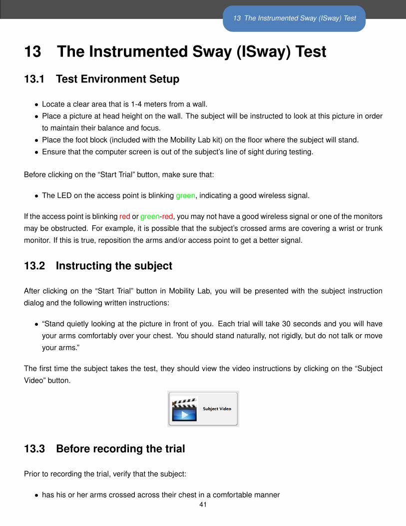
The first time the subject takes the test, they should view the video instructions by clicking on the “Subject
Video” button.
13.3 Before recording the trial
Prior to recording the trial, verify that the subject:
• has his or her arms crossed across their chest in a comfortable manner41

13 The Instrumented Sway (ISway) Test
• is looking at the picture on the wall
13.4 Recording the trial
• To begin recording, press the “Record” button or press the enter key.
• Recording will begin immediately, and a 30 second countdown will begin.
• After the 30 second trial has completed, it will stop automatically.
• The computer will then confirm that the trial has ended by closing the testing window and displaying the
confirmation dialog. Here, you can enter any notes about the recording, if necessary. Choose to either
keep or discard the recording.
• If a subject error occurs during the trial, such as:
– Begins to talk
– Stumbles accidentally
• The examiner can press the “Stop button, stopping the trial in the middle of testing. The examiner
should then inform the subject of the error and how to correct it. If it is believed that the subject can
complete the trial successfully, then the trial should be re-done.
• The subject instructions visible in the dialog box should be read aloud to the subject on each subsequent
TUG trial (within reason) to ensure that the proper behavior is enforced for each trial.
42
13 The Instrumented Sway (ISway) Test
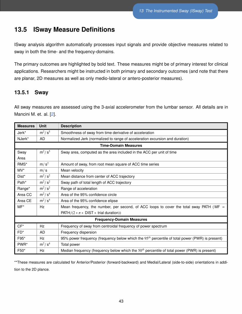
13.5 ISway Measure Definitions
ISway analysis algorithm automatically processes input signals and provide objective measures related to
sway in both the time- and the frequency-domains.
The primary outcomes are highlighted by bold text. These measures might be of primary interest for clinical
applications. Researchers might be instructed in both primary and secondary outcomes (and note that there
are planar, 2D measures as well as only medio-lateral or antero-posterior measures).
13.5.1 Sway
All sway measures are assessed using the 3-axial accelerometer from the lumbar sensor. All details are in
Mancini M. et. al. [2].
Measures Unit Description
Jerk* m2/ s5 Smoothness of sway from time derivative of acceleration
NJerk* AD Normalized Jerk (normalized to range of acceleration excursion and duration)
Time-Domain Measures
Sway
Area
m2/ s5 Sway area, computed as the area included in the ACC per unit of time
RMS* m/ s2 Amount of sway, from root mean square of ACC time series
MV* m/ s Mean velocity
Dist* m2/ s2 Mean distance from center of ACC trajectory
Path* m2/ s2 Sway path of total length of ACC trajectory
Range* m2/ s2 Range of acceleration
Area CC m2/ s4 Area of the 95% confidence circle
Area CE m2/ s4 Area of the 95% confidence elipse
MF* Hz Mean frequency, the number, per second, of ACC loops to cover the total sway PATH ( MF =
PATH/(2 ∗ π ∗ DIST ∗ trial duration))
Frequency-Domain Measures
CF* Hz Frequency of sway from centroidal frequency of power spectrum
FD* AD Frequency dispersion
F95* Hz 95% power frequency (frequency below which the 95th percentile of total power (PWR) is present)
PWR* m2/ s4 Total power
F50* Hz Median frequency (frequency below which the 50th percentile of total power (PWR) is present)
**These measures are calculated for Anterior/Posterior (forward-backward) and Medial/Lateral (side-to-side) orientations in addi-
tion to the 2D plance.
43

14 The Instrumented Stand and Walk (ISAW) Test
14 The Instrumented Stand and Walk (ISAW) Test
14.1 Test Environment Setup
• Measure a 7 meter walkway, with significant space on either side
• Mark the start and finish of the walkway with colored tape on the floor
• Ensure that the computer screen is out of the subject’s line of sight during testing.
14.2 Subject Attire
• The subject should wear clothing that does not bind or impede their movement in any significant way.
• The subject should wear comfortable walking shoes (i.e., no high-heels or flip-flops). If the subject does
not have appropriate shoes, please have them walk barefoot (no socks) and MAKE A NOTE in the
comments section of either the session or each TUG trial.
Before clicking on the “Start Trial” button, make sure that:
• The LED on the access point is blinking green, indicating a good wireless signal.
If the access point is blinking red or green-red, you may not have a good wireless signal or one of the monitors
may be obstructed. For example, it is possible that the subject’s crossed arms are covering a wrist or trunk
monitor. If this is true, reposition the arms and/or access point to get a better signal.
44

14 The Instrumented Stand and Walk (ISAW) Test
14.3 Instructing the Subject
After clicking on the “Start Trial” button in Mobility Lab, you will be presented with the subject instruction
dialog and the following written instructions:
• “Start by standing with your arms at your side. Look straight ahead at a fixed object and remain still
without talking or moving. You should stand naturally, not rigidly. When I say ”Walk”, start walking
forward at a natural and comfortable pace. When you cross the line at the end of the walkway, turn
around, and start walking back. After you cross the line at the beginning of the walkway, stand with your
arms by your side and look straight ahead until you hear the tone or are told the test is complete.”
The first time the subject takes the test, they should view the video instructions by clicking on the “Subject
Video” button.
14.4 Before Recording the Trial
Prior to recording the trial, verify that the subject:
• has his or her arms comfortably by their side
• is standing behind the piece of tape at the start of the walkway
• is looking ahead at a fixed object or picture
14.5 Recording the Trial
• To begin recording, press the “Record” button or press the enter key.
• The time counter will start counting upwards. When it reaches 30s, the test administrator should say
“Walk”.
• During the test the examiner should be “Spotting” the patient as needed (for safety) by walking slightly
to the side and behind the subject so as not to affect their pace.
• When the patient has completed the turn, returned to the start tape strip, and is standing still, press the
“Stop button.45

14 The Instrumented Stand and Walk (ISAW) Test
• The system will continue collecting data for 3 seconds. Please ensure that the patient is motionless
during this time.
• The computer will then confirm that the trial has ended by closing the testing window and displaying the
confirmation dialog. Here, you can enter any notes about the recording, if necessary. Choose to either
keep or discard the recording.
• If a subject error occurs during the trial, such as:
– Incompletion of the course.
– The subject uses his/her hands during sit-stand or stand-sitnot due to necessity.
– The subject does not fully cross the line.
– The subject makes an incorrect turn (goes around the line, instead of across).
• The examiner can press the “Stop button, stopping the trial in the middle of testing. The examiner
should then inform the subject of the error and how to correct it. If it is believed that the subject can
complete the trial successfully, then the trial should be re-done.
• The subject instructions visible in the dialog box should be read aloud to the subject on each subsequent
ISAW trial (within reason) to ensure that the proper behavior is enforced for each trial.
46

14 The Instrumented Stand and Walk (ISAW) Test
14.6 ISAW Measure Definitions
The Instrumented Stand and Walk (ISAW) analysis algorithms automatically processes recorded movement
data and provide objective measures related to four major components of the test: sway, gait, anticipatory
postural adjustments (APA), and turning.
The primary outcomes in each table are highlighted by bold text. These measures might be of primary
interest for clinical applications. Researchers might be interested in both primary and secondary outcomes.
14.6.1 Sway
All sway measures are assessed using the 3-axial accelerometer from the lumbar sensor. All details are in
Mancini M. et. al. [2].
Measures Unit Description
Jerk* m2/ s5 Smoothness of sway from time derivative of acceleration
NJerk* AD Normalized Jerk (normalized to range of acceleration excursion and duration)
Time-Domain Measures
Sway
Area
m2/ s5 Sway area, computed as the area included in the ACC per unit of time
RMS* m/ s2 Amount of sway, from root mean square of ACC time series
MV* m/ s Mean velocity
Dist* m2/ s2 Mean distance from center of ACC trajectory
Path* m2/ s2 Sway path of total length of ACC trajectory
Range* m2/ s2 Range of acceleration
Area CC m2/ s4 Area of the 95% confidence circle
Area CE m2/ s4 Area of the 95% confidence elipse
MF* Hz Mean frequency, the number, per second, of ACC loops to cover the total sway PATH ( MF =
PATH/(2 ∗ π ∗ DIST ∗ trial duration))
Frequency-Domain Measures
CF* Hz Frequency of sway from centroidal frequency of power spectrum
FD* AD Frequency dispersion
F95* Hz 95% power frequency (frequency below which the 95th percentile of total power (PWR) is present)
PWR* m2/ s4 Total power
F50* Hz Median frequency (frequency below which the 50th percentile of total power (PWR) is present)
**These measures are calculated for Anterior/Posterior (forward-backward) and Medial/Lateral (side-to-side) orientations in addi-
tion to the 2D plance.
47

14 The Instrumented Stand and Walk (ISAW) Test
14.6.2 Step Initiation (APA)
All details are in Mancini M. et. al. [1].
Measures Unit Description
APA ML amplitude m/ s2 Peak acceleration toward the stance foot of the lateral trunk acceleration
APA AP amplitude m2/ s2 Peak trunk acceleration forward from baseline
APA Duration Time (s) Time from APA onset to end
First Step Latency Time (s) Time-to-peak angular velocity of the stepping leg from the APA onset
First Step Length Degrees Range of motion of the shank (calculated from the integrated sagittal angular
velocity)
14.6.3 Gait
Gyroscopes attached on the shanks are used to detect the basic gait events, i.e. time feet hit the ground
and leave the ground (initial and terminal contacts). Temporal gait measures are then calculated based on
the time of gait events. In the next step, ranges of motions (RoM) of the shank segments are estimated
by integrating the gyroscopes signals. Finally, spatial gait measures are estimated using a biomechanical
model [6]. Gait measures are reported for individual gait cycles in the CSV export. A gait cycle is defined as
the period between two consecutive initial contacts (heel-strike) of the right foot.
Spatial gait measures
Measures Unit Sensors Description
Stride Length % of Subjects body
height*
Shanks Distance between two consecutive foot falls at the moments of ini-
tial contacts. Averaged for left and right side. The value is normal-
ized for height.
Stride Length R % of Subjects
height*
Shanks Distance between two consecutive right foot falls at the moments
of initial contacts
Stride Length L % of Subjects
height*
Shanks Distance between two consecutive left foot falls at the moments of
initial contacts
Stride Velocity % of Subjects
height / second*
Shanks Walking speed. Average of the right and left sides.
Stride Velocity R % of Subjects
height / second*
Shanks Walking speed of right leg
Stride Velocity L % of Subjects
height / second*
Shanks Walking speed of left leg
*Values are given relative to the subject’s body height to enable comparison to normative data. If the subject’s
height is entered through Mobility Lab, then values will additionally be provided in units of meters.
48

14 The Instrumented Stand and Walk (ISAW) Test
Temporal gait measures
Measures Unit Sensors Description
Cadence Steps / minute Shanks Stepping rate
Gait Cycle Time Time (seconds) Shanks Duration of a complete gait cycle
Double Support % of GCT Shanks Percentage of a gait cycle that both feet are on the ground
Swing % of GCT Shanks Average percentage of a gait cycle that either foot is off the ground
Swing R % of GCT Shanks Percentage of a gait cycle that right foot is off the ground
Swing L % of GCT Shanks Percentage of a gait cycle that left foot is off the ground
Stance % of GCT Shanks Average percentage of a gait cycle that either foot is on the ground
Stance R % of GCT Shanks Percentage of a gait cycle that right foot is on the ground
Stance L % of GCT Shanks Percentage of a gait cycle that left foot is on the ground
Initial Contact R Time (seconds) Shanks The time (relative to the beginning of the trial) that right foot hits
the ground. Sometimes referred to as heel-strike.
Terminal Contact L Time (seconds) Shanks The time (relative to the beginning of the trial) that right foot leaves
the ground. Sometimes referred to as toe-off.
Initial Contact L Time (seconds) Shanks The time (relative to the beginning of the trial) that left foot hits the
ground.
Terminal Contact L Time (seconds) Shanks The time (relative to the beginning of the trial) that left foot leaves
the ground.
49

14 The Instrumented Stand and Walk (ISAW) Test
Ranges of motions (RoM) and angular velocities
Measures Unit Sensors Description
Shank RoM Degrees Shanks RoM of shanks; averaged of the left and right sides.
RoM Shank R Degrees Shanks RoM of right shank.
RoM Shank L Degrees Shanks RoM of left shank.
Peak Shank
Velocity
Degrees / seconds Shanks Peak (95%) angular velocity of shanks. Average of the left and
right sides.
Peak Shank
Velocity R
Degrees / seconds Shanks Peak (95%) angular velocity of right shank.
Peak Shank
Velocity L
Degrees / seconds Shanks Peak (95%) angular velocity of left shank.
Peak Arm Velocity Degrees / second Shanks +
Arms
Peak (95%) angular velocity of arms. Average of the left and right
sides.
Peak Arm Velocity
R
Degrees/ second Shanks +
Arms
Peak (95%) angular velocity of right arm. Measured as the norm
of 3D angular velocity vector.
Peak Arm Velocity L Degrees/ second Shanks +
Arms
Peak (95%) angular velocity of left arm. Measured as the norm of
3D angular velocity vector.
Arm-Swing
Velocity
Asymmetry
% Shanks +
Arms
Asymmetry of left/right arm-swing angular velocity. Defined as the
difference between the two sides as percentage of the fastest side.
Arm RoM Degrees Shanks +
Arms
RoM of arms during arm-swing. Average of the left and right sides.
RoM Arm R Degrees Shanks +
Arms
RoM of right Arm. Measures as the norm of 3D arm rotation vector.
RoM Arm L Degrees Shanks +
Arms
RoM of right Arm. Measures as the norm of 3D arm rotation vector.
Trunk Sagittal RoM Degrees Shanks +
Trunk
RoM of trunk in sagittal plane.
Trunk Horizontal
RoM
Degrees Shanks +
Trunk
RoM of trunk in horizontal plane.
Trunk Sagittal
Peak Velocity
Degrees /second Shanks +
Trunk
Peak angular velocity of trunk in sagittal plane.
Trunk Horizontal
Peak Velocity
Degrees / second Shanks +
Trunk
Peak angular velocity of trunk in horizontal plane.
50

14 The Instrumented Stand and Walk (ISAW) Test
14.6.4 Turn
Turning is detected and assessed based using gyroscopes within the trunk or lumbar sensor. A mathematical
model is used to detect the exact moment of beginning and end of turning [4].
Measures Unit Sensors Description
Turning Duration Time (seconds) Trunk Duration of 180 turn. Measured according to the mathematical
model of turning.
Number of Steps Number Shanks +
Trunk
Number of steps during 180 turn. Steps which are at least 50%
within turning period are counted.
Peak Turning
Velocity
Degrees / second Trunk Peak (95%) angular velocity of turnk during turning.
Step time Time (seconds) Shanks +
Trunk
Average step duration during turning.
Step time before
turn
Time (seconds) Shanks +
Trunk
The last step duration right before the turn.
51

15 The Instrumented Long Walk (IWalk) Test
15 The Instrumented Long Walk (IWalk) Test
15.1 Test Environment Setup
• The IWalk is an open ended test, requiring only that the subject walk at least 5 full gait cycles.
• The walkway should be straight.
• It is not required that a turn be present in the walkway, but it needs to be a 180 degree turn to ensure
proper detection and to be comparable with the normative turn measure data.
• Each trial can include any number of turns (i.e., the subject can walk back and forth any number of
times).
15.2 Subject Attire
• The subject should wear clothing that does not bind or impede their movement in any significant way.
• The subject should wear comfortable walking shoes (i.e., no high-heels or flip-flops). If the subject does
not have appropriate shoes, please have them walk barefoot (no socks) and MAKE A NOTE in the
comments section of either the session or each TUG trial.
Before clicking on the “Start Trial” button, make sure that:
• The LED on the access point is blinking green, indicating a good wireless signal.
If the access point is blinking red or green-red, you may not have a good wireless signal or one of the monitors
may be obstructed. For example, it is possible that the subject is covering one of the monitors with a limb. If
this is true, reposition the subject and/or reposition the access point to get a better signal. If the walkway is
52
15 The Instrumented Long Walk (IWalk) Test
longer than the range of the monitors ( 30m with good line of site), the data will be buffered on the monitors
themselves, and will stream to the computer when back within range. If there is a lot of catch up to do when
the trial is finished, there will be a progress indicator to show how much of the buffered data still needs to be
sent before saving the trial.
15.3 Instructing the Subject
After clicking on the “Start Trial” button in Mobility Lab, you will be presented with the subject instruction
dialog and the following written instructions:
• “When I say ”Walk”, start walking at a natural and comfortable pace. When I say ”Stop”, stop where you
are and wait for the beep or are told the test is complete.”
The first time the subject takes the test, they should view the video instructions by clicking on the “Subject
Video” button.
15.4 Before Starting the Trial
Prior to recording the trial, verify that the subject:
• is relaxed
• is standing and prepared to start walking
15.5 Recording the Trial
• To begin recording, press the “Record” button or press the enter key.
• After clicking on the “Record” button, the test administrator should say “Walk”.
• During the test the examiner should be “Spotting” the patient as needed (for safety) by walking slightly
to the side and behind the subject so as not to affect their pace.
• When the trial is complete, press the Stop button and tell the subject they can stop walking.
53

15 The Instrumented Long Walk (IWalk) Test
• The computer will then confirm that the trial has ended by closing the testing window and displaying the
confirmation dialog. Here, you can enter any notes about the recording, if necessary. Choose to either
keep or discard the recording.
• If a subject error occurs during the trial, such as:
– Incompletion of the course
– Falling
• The examiner can press the Stop button, stopping the trial in the middle of testing. The examiner should
then inform the subject of the error or problem and how to correct it. If it is believed that the subject can
complete the trial successfully and safely, then the trial should be re-done.
• The subject instructions visible in the dialog box should be read aloud to the subject on each subsequent
TUG trial (within reason) to ensure that the proper behavior is enforced for each trial.
15.6 IWalk Measure Definitions
The Instrumented Walk (IWalk) analysis algorithms automatically processes recorded movement data and
provide objective measures related to gait and turning.
The primary outcomes in each table are highlighted by bold text. These measures might be of primary
interest for clinical applications. Researchers might be interested in both primary and secondary outcomes.
15.6.1 Gait
Gyroscopes attached on the shanks are used to detect the basic gait events, i.e. time feet hit the ground
and leave the ground (initial and terminal contacts). Temporal gait measures are then calculated based on
the time of gait events. In the next step, ranges of motions (RoM) of the shank segments are estimated
by integrating the gyroscopes signals. Finally, spatial gait measures are estimated using a biomechanical
model [6]. Gait measures are reported for individual gait cycles in the CSV export. A gait cycle is defined as
the period between two consecutive initial contacts (heel-strike) of the right foot.
54

15 The Instrumented Long Walk (IWalk) Test
Spatial gait measures
Measures Unit Sensors Description
Stride Length % of Subjects body
height*
Shanks Distance between two consecutive foot falls at the moments of ini-
tial contacts. Averaged for left and right side. The value is normal-
ized for height.
Stride Length R % of Subjects
height*
Shanks Distance between two consecutive right foot falls at the moments
of initial contacts
Stride Length L % of Subjects
height*
Shanks Distance between two consecutive left foot falls at the moments of
initial contacts
Stride Velocity % of Subjects
height / second*
Shanks Walking speed. Average of the right and left sides.
Stride Velocity R % of Subjects
height / second*
Shanks Walking speed of right leg
Stride Velocity L % of Subjects
height / second*
Shanks Walking speed of left leg
*Values are given relative to the subject’s body height to enable comparison to normative data. If the subject’s
height is entered through Mobility Lab, then values will additionally be provided in units of meters.
Temporal gait measures
Measures Unit Sensors Description
Cadence Steps / minute Shanks Stepping rate
Gait Cycle Time Time (seconds) Shanks Duration of a complete gait cycle
Double Support % of GCT Shanks Percentage of a gait cycle that both feet are on the ground
Swing % of GCT Shanks Average percentage of a gait cycle that either foot is off the ground
Swing R % of GCT Shanks Percentage of a gait cycle that right foot is off the ground
Swing L % of GCT Shanks Percentage of a gait cycle that left foot is off the ground
Stance % of GCT Shanks Average percentage of a gait cycle that either foot is on the ground
Stance R % of GCT Shanks Percentage of a gait cycle that right foot is on the ground
Stance L % of GCT Shanks Percentage of a gait cycle that left foot is on the ground
Initial Contact R Time (seconds) Shanks The time (relative to the beginning of the trial) that right foot hits
the ground. Sometimes referred to as heel-strike.
Terminal Contact L Time (seconds) Shanks The time (relative to the beginning of the trial) that right foot leaves
the ground. Sometimes referred to as toe-off.
Initial Contact L Time (seconds) Shanks The time (relative to the beginning of the trial) that left foot hits the
ground.
Terminal Contact L Time (seconds) Shanks The time (relative to the beginning of the trial) that left foot leaves
the ground.
55

15 The Instrumented Long Walk (IWalk) Test
Ranges of motions (RoM) and angular velocities
Measures Unit Sensors Description
Shank RoM Degrees Shanks RoM of shanks; averaged of the left and right sides.
RoM Shank R Degrees Shanks RoM of right shank.
RoM Shank L Degrees Shanks RoM of left shank.
Peak Shank
Velocity
Degrees / seconds Shanks Peak (95%) angular velocity of shanks. Average of the left and
right sides.
Peak Shank
Velocity R
Degrees / seconds Shanks Peak (95%) angular velocity of right shank.
Peak Shank
Velocity L
Degrees / seconds Shanks Peak (95%) angular velocity of left shank.
Peak Arm Velocity Degrees / second Shanks +
Arms
Peak (95%) angular velocity of arms. Average of the left and right
sides.
Peak Arm Velocity
R
Degrees/ second Shanks +
Arms
Peak (95%) angular velocity of right arm. Measured as the norm
of 3D angular velocity vector.
Peak Arm Velocity L Degrees/ second Shanks +
Arms
Peak (95%) angular velocity of left arm. Measured as the norm of
3D angular velocity vector.
Arm-Swing
Velocity
Asymmetry
% Shanks +
Arms
Asymmetry of left/right arm-swing angular velocity. Defined as the
difference between the two sides as percentage of the fastest side.
Arm RoM Degrees Shanks +
Arms
RoM of arms during arm-swing. Average of the left and right sides.
RoM Arm R Degrees Shanks +
Arms
RoM of right Arm. Measures as the norm of 3D arm rotation vector.
RoM Arm L Degrees Shanks +
Arms
RoM of right Arm. Measures as the norm of 3D arm rotation vector.
Trunk Sagittal RoM Degrees Shanks +
Trunk
RoM of trunk in sagittal plane.
Trunk Horizontal
RoM
Degrees Shanks +
Trunk
RoM of trunk in horizontal plane.
Trunk Sagittal
Peak Velocity
Degrees /second Shanks +
Trunk
Peak angular velocity of trunk in sagittal plane.
Trunk Horizontal
Peak Velocity
Degrees / second Shanks +
Trunk
Peak angular velocity of trunk in horizontal plane.
56

15 The Instrumented Long Walk (IWalk) Test
Symmetry Measures
Measures Unit Sensors Description
Stride Velocity
Asymmetry
% Shanks Mean asymmetry of the left and right stride velocities
Stride Length
Asymmetry
% Shanks Mean asymmetry of the left and right stride lenghts
Swing Asymmetry % Shanks Mean asymmetry of the left and right swing (percentage of a gait
cycle that either foot is off the ground)
Stance Asymmetry % Shanks Mean asymmetry of the left and right stance (percentage of a gait
cycle that either foot is on the ground)
Shank Asymmetry % Shanks Mean asymmetry of the left and right shank rotations
Peak Shank
Velocity Asymmetry
% Shanks Mean asymetry of the left and right shank velocities
Peak Arm Velocity
Asymmetry
% Arms Mean asymmetry of the left and right arm swing velocities
Arm SSI % Arms Arm Symbolic Symmetry Index [7]
Shank SSI % Shanks Shank Symbolic Symmetry Index [7]
Phase Difference % Shanks The phase relationship between the left and right legs [3]
Phase Coordination
Index
% Shanks A measure of the consistency and accuracy in the generation of
anti-phased left/right leg movements [3]
57

15 The Instrumented Long Walk (IWalk) Test
15.6.2 Turn
Turning is detected and assessed based using gyroscopes within the trunk or lumbar sensor. A mathematical
model is used to detect the exact moment of beginning and end of turning [4].
Measures Unit Sensors Description
Turning Duration Time (seconds) Trunk Duration of 180 turn. Measured according to the mathematical
model of turning.
Number of Steps Number Shanks +
Trunk
Number of steps during 180 turn. Steps which are at least 50%
within turning period are counted.
Peak Turning
Velocity
Degrees / second Trunk Peak (95%) angular velocity of turnk during turning.
Step time Time (seconds) Shanks +
Trunk
Average step duration during turning.
Step time before
turn
Time (seconds) Shanks +
Trunk
The last step duration right before the turn.
58
16 When You Are Done
16 When You Are Done
16.1 Docking Monitors
In most situations, it is sufficient to simply dock your monitors when not in use. When docked, monitors stop
recording, stop broadcasting, and start charging their batteries. Once fully charged, the batteries will enter a
trickle charge mode to keep them topped off.
16.2 Power Off
For transport or storage, it is often desirable to power off all system components. This can be done by
docking the monitors and clicking on the “Power Off” button in the bottom left corner. The monitors will power
down the next time they are undocked.
59

17 External Synchronization and I/O
17 External Synchronization and I/OThe access point comes with external connectors that enable you to synchronize the recording of data in
Mobility Lab with external equipment. This functionality only works when the system is configured in one of
the wireless streaming modes and the “Stream” dialog is open. The implementation is adaptable to a number
of scenarios. Here are some examples of things you can do:
• Trigger recording in Mobility Lab when external events occur. You can use this functionality to precisely
synchronize your inertial recordings with, for example, recordings initiated on a camera based motion
capture system.
• Trigger external events when you start and stop recording in Mobility Lab. You can use this functionality
to precisely synchronize your inertial recordings initiated in Mobility Lab with, to use another example,
a video recording system.
• A combination of the two. For example, hitting the record button on a camera based motion capture
system could trigger recording in Mobility Lab which could then trigger a video recording system.
The External Synchronization Configuration Dialog
60
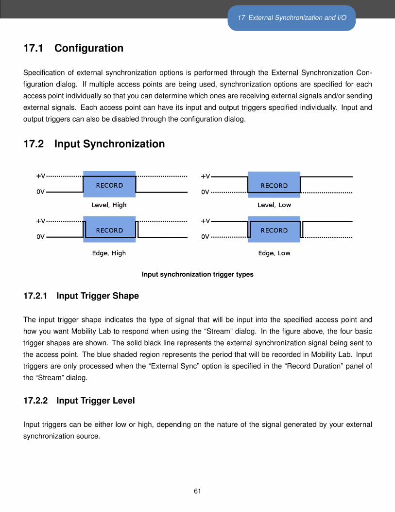
17 External Synchronization and I/O
17.1 Configuration
Specification of external synchronization options is performed through the External Synchronization Con-
figuration dialog. If multiple access points are being used, synchronization options are specified for each
access point individually so that you can determine which ones are receiving external signals and/or sending
external signals. Each access point can have its input and output triggers specified individually. Input and
output triggers can also be disabled through the configuration dialog.
17.2 Input Synchronization
Input synchronization trigger types
17.2.1 Input Trigger Shape
The input trigger shape indicates the type of signal that will be input into the specified access point and
how you want Mobility Lab to respond when using the “Stream” dialog. In the figure above, the four basic
trigger shapes are shown. The solid black line represents the external synchronization signal being sent to
the access point. The blue shaded region represents the period that will be recorded in Mobility Lab. Input
triggers are only processed when the “External Sync” option is specified in the “Record Duration” panel of
the “Stream” dialog.
17.2.2 Input Trigger Level
Input triggers can be either low or high, depending on the nature of the signal generated by your external
synchronization source.
61

17 External Synchronization and I/O
17.2.3 Input Trigger
There are three input trigger options available:
• Start: The external trigger will only be used to start recording in Mobility Lab.
• End: The external trigger will only be used to stop recording in Mobility Lab.
• Both: The external trigger will be used to start and stop recording in Mobility Lab.
17.2.4 Sample Selection with External Input Trigger Events
The time of the external input trigger events may not align exactly with the time of an individual samples being
collected in Mobility Lab due to the discreet sampling interval. If the start trigger event time does happen
to align exactly with a sample captured in Mobility Lab, the first sample recorded will correspond exactly to
the time of the start trigger event. If these do not align exactly (as will generally be the case) the sample
preceding the start trigger event will be the first sample recorded. Similarly, if the stop trigger event aligns
exactly with a sample captured in Mobility Lab, the last sample recorded will correspond exactly to the time
of the stop trigger event. If these do not align exactly, the sample following the start trigger event will be the
last sample recorded. This way, we guarantee that the recording captured in Mobility Lab fully spans the time
period between the external input start and stop events, but no more.
17.2.5 Annotation of Externally Triggered Recordings
Note: Annotations are implemented for the HDF file format only. When an external “Start” trigger event is
detected, an annotation is added to the recording that indicates the name of the event (in this case “External
trigger start time”) along with the timestamp of the event in epoch microseconds. Similarly, when an external
“Stop” trigger event is detected, a timestamped annotation is added to the recording (in this case labeled
as the “External trigger stop time”). These annotations allow you to align the recording captured in Mobility
Lab with your external events in the case where the external trigger event times do not exactly align with the
samples captured in your HDF file.
17.3 Output Synchronization
17.3.1 Output Trigger Shape
The output trigger shape indicates the type of signal that will be generated by the specified access point
when recording is started and stopped through the streaming dialog in Mobility Lab. The output trigger
shapes are identical to the input trigger shapes, but in this case the solid black line in the figure above
represents the signal being output by the configured access point. The blue shaded region represents the
62

17 External Synchronization and I/O
Output synchronization trigger types
period being recorded in Mobility Lab, initiated either through user selection of the start/stop buttons in the
“Stream” dialog, use of the wireless remote, or an external synchronization event. Unlike input triggers,
output triggers are processed even if the “External Sync” option is not specified in the “Record Duration”
panel of the “Stream” dialog.
17.3.2 Output Trigger Level
Output triggers can be either low or high, depending on the requirements of the external system receiving
the synchronization signal.
17.3.3 Output Trigger
There are three output trigger options available:
• Start: The external signal will only be generated when recording is started in Mobility Lab.
• End: The external signal will only be generated when recording is stopped in Mobility Lab.
• Both: The external signal will be generated when recording is started and stopped in Mobility Lab.
• Note: It is not recommended to use the level trigger shapes in conjunction with the start or end triggers.
This is because the output signal will be in an undeterministic state prior to the trigger event.
17.4 Isolated External Interface Details
APDM’s access points come fitted with a 6 pin digital I/O connector and a 4 pin analog I/O connector. To
connect an access point to your external equipment, you may have to create a custom cable that can interface
with both components. Below we provide the technical specifications necessary to complete this task. Feel
free to contact our technical support at [email protected] if you require assistance or have additional
questions.
63

17 External Synchronization and I/O
The Isolated External Interface for the AP consists of an auxiliary power supply, two GPIO lines (one in, one
out), and an inter-AP sync signal. All signals in the isolated external interface section (including power and
ground) are isolated from the remainder of the board using an RF solution similar in operation to an opto-
isolator. Further, all signals in the isolated external interface are 5V tolerant and ESD protected beyond the
15kV human body model.
The connectors used in the isolated interface consist of one standard female RCA, and one female 6 pin
mini-din connector. The RCA connector mates to almost any basic RCA cable similar to those used in audio
systems. When choosing an RCA mating connector, choose one that has uncovered bare shield spades to
allow the connector to fit fully into the recessed hollow in the AP body.
The 6 pin mini-din connector is similar to those used for older style PS/2 keyboards and mice. Choose a
connector that is small enough to fit fully inside the recessed hollow in the AP body. Some PS/2 extension
cables can be cut into excellent pigtails for this connector.
17.4.1 RCA Inter-AP Sync Connector
• RCA Connector: Digikey Part number RCP-021, CUI INC
• Center Pin: Inter-AP Sync
• Sheild: Isolated Ground
17.4.2 6 Pin Digital Input/Output Connector
• 6 Pin Mating Connector: Digikey part number CP-2060-ND, CUI Inc part number MD-60.
• 6 Pin Mating Pig Tail Cable: Digikey part number 839-1051-ND
• Note these connectors may need the outer shell trimmed to fit into the AP case, a better solution is
often pigtail cables that have over-molded ends and excellent strain relief.
AP 6 Pin Digital Connector
• Pin 1: Record In
64

17 External Synchronization and I/O
• Pin 2: Output Voltage Select. When connected to positive (pin 6), I/O will be in 5 volt mode. 3.3 volt
mode otherwise.
• Pin 3: Isolated Ground (isolated gnd)
• Pin 4: Inter-AP synchronization output signal. 2.56 khz square wave used for synchronizing timing
among multiple access points.
• Pin 5: Record Out
• Pin 6: Isolated Vdd, unregulated. 3.3 V or 5 V depending on whether it is connected to pin 2.
The auxiliary power supply is meant to provide for powered external interface solutions, allowing a small
circuit to be powered directly from the AP. Accessed via pin 6 of the mini-din connector, the auxiliary power
supply is rated for operation up to 250mW at 3.3V or 5V operation. While default operation is at 3.3V, 5V
operation can be selected by shorting pin 2 to pin 6 of the 6 pin mini-din connector.
The inter-AP sync signal is a 2.56kHz clock signal used to keep multiple AP configurations in sync with one
another. The inter-AP sync signal is available on the RCA connector, as well as pin 4 of the 6 pin mini-din
connector next to it. The signal is a square wave pulse that is driven by the ’master’ AP (usually the first AP
to enumerate) and received by up to seven additional APs (depending on output voltage selection and cable
length). In operation the signal is weakly pulled up to the isolated power rail by each AP in the system, and
driven directly to ground only by the ’master’ AP to produce the pulsed waveform.
Two GPIO lines are available, one input and one output. Both are pulled down by 47.5kΩ resistors, and
each have a series resistance of nearly 1.2kΩ due to the methods used to protect the lines from over-
voltage/overcurrent conditions. The input signal is available on pin 1 of the 6 pin mini-din connector and
is typically used to start/stop data collection by the host PC. Driving the line high to ’record’ and low to
’not-record’ is the default operation, though this is user selectable in software to allow for other modes of
operation. Similar to the input line, the output line is typically used to start/stop data capture on external
systems. The line is driven high by the AP when ’start recording’ is selected in software, and driven low when
recording stops. Opposite high/low operation can be software selected at time of configuration for both input
and output signals.
• Note: The pin diagrams below show the interface on the AP and not the cable. The pin layout on the
cable is the mirror image of these diagrams.
• Note: A cable designed to trigger recording in Mobility Lab from an external synchronization event must
make use of isolated ground (pin 3) and record in (pin 1). Assuming a voltage range of 3.3V, these are
the only pins that need to be implemented. If the voltage range is 5V, pins 2 and 6 must be connected.
• Note: A cable designed to trigger an external system when recording is started or stopped in Mobility
Lab must make use of isolated ground (pin 3) and record out (pin 5). Assuming a voltage range of 3.3V,
these are the only pins that need to be implemented. If the voltage range is 5V, pins 2 and 6 must be
connected.
65

17 External Synchronization and I/O
17.4.3 External Sync Box
The external sync box is meant to allow for easy access to the access point external digital expansion port.
A shielded straight-through six conductor cable connects the AP to the sync box, BNC connections outside
the box allow for simple connections to remote equipment.
AP External Sync Box
Three external BNC connections:
• AP-AP: This connection should only be connected to another AP, it is used to keep multiple APs in sync
and can be used to connect multiple APs in a star or daisy chain configuration (both will work).
• AP In: This input to the AP can be configured via software to allow an external device to begin and stop
recordings. Accepts both +3.3V and +5V logic levels.
• AP Out: This AP output can be configured via software to drive low, high, or pulse at record start/stop
points allowing synchronization with an external system (such as a camera motion capture system).
Note: the default configuration for AP Out is +3.3V logic levels, though +5V levels can be selected
using the voltage select switch located in the top of the box.
Four LEDs indicators:
• PWR: Lights when power is applied to the external interface.
• +5V: Lights to indicate that the external interface is configured for 5V operation. Default is 3.3V (Light
out)
• AP In: Lights to indicate that the APlIn signal is High
• AP Out: Lights to indicate that the AP Out signal is High
Push-button and Toggle switch:
• Push Button: Up to select 3.3V operation. Down to select 5V operation.
• Toggle: Manually ties the AP In signal to the positive voltage rail allowing for manual triggering of
recordings (software configured).
66

17 External Synchronization and I/O
Additional connections and functionality are located inside the box and can be accessed by removal of the
box top: JP1 through JP4 can be removed to disconnect the corresponding LED.
Six Euro-style screw terminals can be used to directly connect to the six wires in the AP cable:
AP External Sync Box
• +V: Positive voltage rail from the isolated supply located inside the AP.
• GND: Ground rail from the isolated supply located inside the AP.
• VSEL: Tie to Ground or leave floating to select output and +V operation at +3.3V, tie to +V to select +5V
operation.
• AP-AP: Allows multiple AP configurations, tie only to the same port of another AP.
• AP Out: Digital output from the AP. Default is 0V to +3.3V, but can be configured for 0-5V operation.
• AP In: Digital input to the AP from an external source or the manual trigger toggle switch.
Note: The AP is able to safely source only 50mA on the +V rail.
67

17 External Synchronization and I/O
17.4.4 4 Pin Analog Input/Output Connector
Note: This connector is currently reserved for future expansion.
• 4 Pin Mating Connector: Digikey part number CP-2040-ND, CUI Inc part number MD-40
• 4 Pin Mating Pig Tail Cable: Digikey part number 839-1049-ND
AP 4 Pin Analog Connector
• Pin 1: Analog In (0 to 6 volts)
• Pin 2: Analog Out (0 to 5 volts or 0 to 3.3 volts depending on software controled configuration)
• Pin 3: No Connect (reserved for future use, avoid connecting this pin)
• Pin 4: Ground (gnd). This is the same ground as USB, and depending on how your USB hub and/or
laptop are designed electrically, may also be the same ground as the hub and laptop. Consideration
should be taken for ground loops.
17.4.5 Schematic
68

18 Firmware Updates
18 Firmware UpdatesFirmware controls the various hardware components of your APDM product line (monitors, access points,
and docking stations). It is important to keep the firmware up to date to ensure that your system gets the
latest bug fixes and has access to the latest features. Firmware updates are bundled with updates to Mobility
Lab. Firmware can be updated either automatically or manually.
18.1 Automatic Firmware Updates
Whenever you configure your system, your hardware is first checked to ensure that the latest firmware is
installed. If not, you will be prompted to automatically update your hardware to the latest versions of the
firmware bundled with your system.
18.2 Manual Firmware Updates
Firmware can be updated manually as well. This functionality can be used to either flash the default firmware
to one of the hardware components, or to flash a different version. To access the “Update Firmware” dialog,
click on “Tools→ Update Firmware” in the menu bar.
The manual firmware update tool
18.2.1 Flash Default Firmware
Your system comes bundled with an up to date version of the firmware. Pressing this button will re-flash this
version of the firmware onto the specified monitor.
18.2.2 Flash Alternate Firmware
For testing purposes or to address an issue in a timely fashion, it may be necessary to flash a monitor with
a version of the firmware that is different than the bundled version. You will have to specify the alternate
firmware file to use with this option.
69

18 Firmware Updates
18.2.3 Force Update
When using either of the options above, if the firmware version on the target device(s) matches the firmware
version to be flashed, the device will be skipped. If the “Force update even if versions match” checkbox is
selected, however, the firmware will be flashed even if the versions match. This may be necessary in some
cases to recover a malfunctioning device.
70
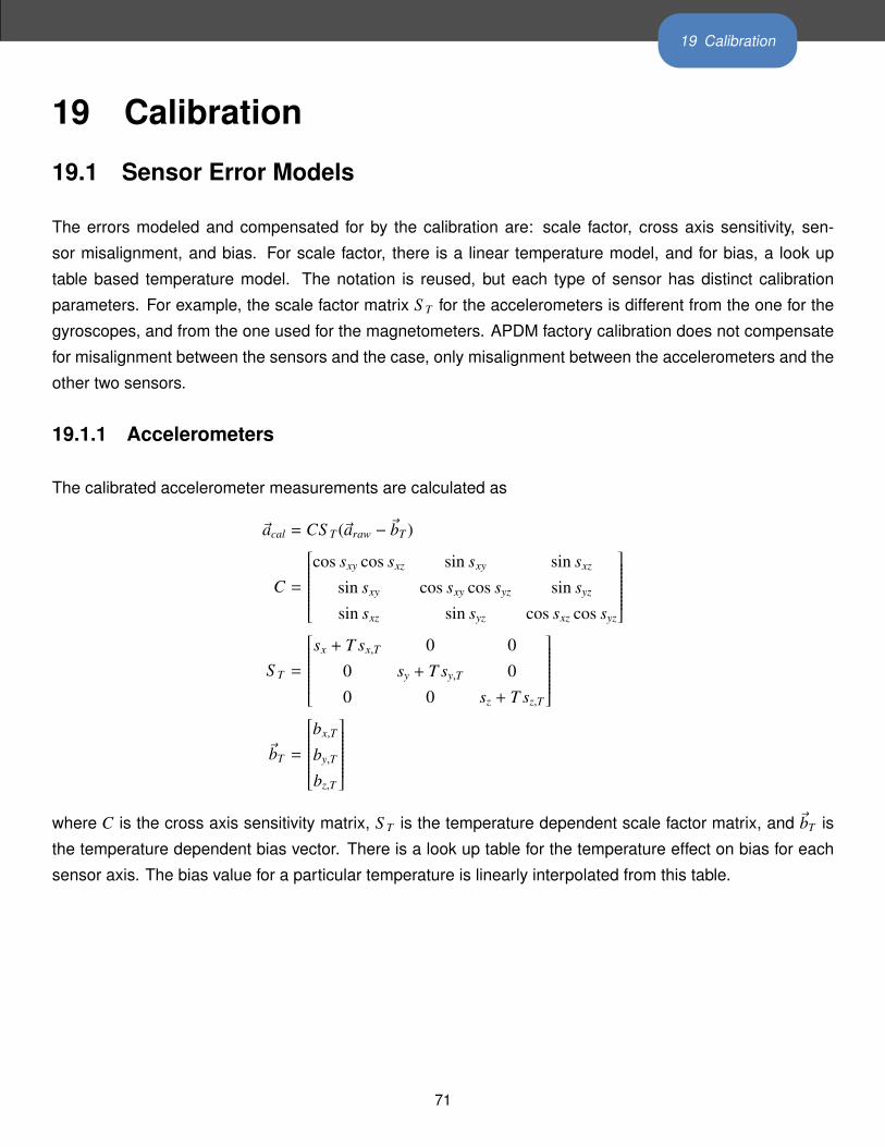
19 Calibration
19 Calibration
19.1 Sensor Error Models
The errors modeled and compensated for by the calibration are: scale factor, cross axis sensitivity, sen-
sor misalignment, and bias. For scale factor, there is a linear temperature model, and for bias, a look up
table based temperature model. The notation is reused, but each type of sensor has distinct calibration
parameters. For example, the scale factor matrix S T for the accelerometers is different from the one for the
gyroscopes, and from the one used for the magnetometers. APDM factory calibration does not compensate
for misalignment between the sensors and the case, only misalignment between the accelerometers and the
other two sensors.
19.1.1 Accelerometers
The calibrated accelerometer measurements are calculated as
~acal = CS T (~araw − ~bT )
C =
cos sxy cos sxz sin sxy sin sxz
sin sxy cos sxy cos syz sin syz
sin sxz sin syz cos sxz cos syz
S T =
sx + T sx,T 0 0
0 sy + T sy,T 00 0 sz + T sz,T
~bT =
bx,T
by,T
bz,T
where C is the cross axis sensitivity matrix, S T is the temperature dependent scale factor matrix, and ~bT is
the temperature dependent bias vector. There is a look up table for the temperature effect on bias for each
sensor axis. The bias value for a particular temperature is linearly interpolated from this table.
71
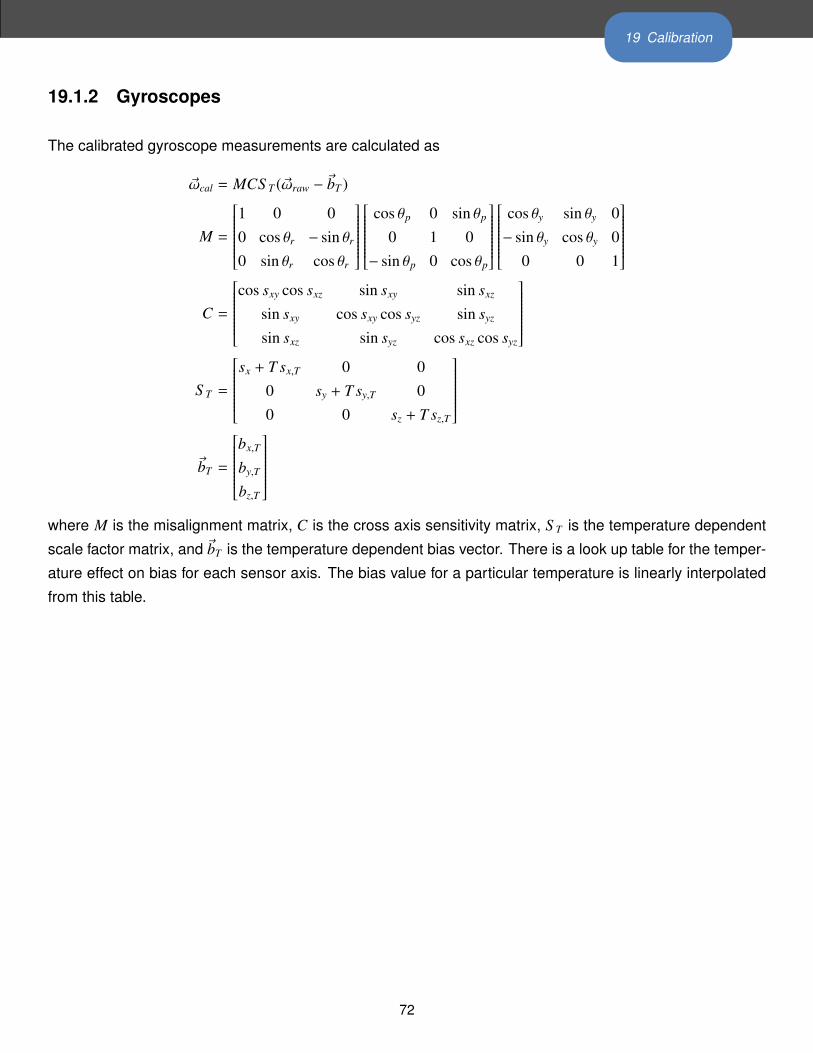
19 Calibration
19.1.2 Gyroscopes
The calibrated gyroscope measurements are calculated as
~ωcal = MCS T (~ωraw − ~bT )
M =
1 0 00 cos θr − sin θr
0 sin θr cos θr
cos θp 0 sin θp
0 1 0− sin θp 0 cos θp
cos θy sin θy 0− sin θy cos θy 0
0 0 1
C =
cos sxy cos sxz sin sxy sin sxz
sin sxy cos sxy cos syz sin syz
sin sxz sin syz cos sxz cos syz
S T =
sx + T sx,T 0 0
0 sy + T sy,T 00 0 sz + T sz,T
~bT =
bx,T
by,T
bz,T
where M is the misalignment matrix, C is the cross axis sensitivity matrix, S T is the temperature dependent
scale factor matrix, and ~bT is the temperature dependent bias vector. There is a look up table for the temper-
ature effect on bias for each sensor axis. The bias value for a particular temperature is linearly interpolated
from this table.
72

19 Calibration
19.1.3 Magnetometers
The calibrated magnetometer measurements are calculated as
~mcal = MCS T (~mraw − ~bT )
M =
1 0 00 cos θr − sin θr
0 sin θr cos θr
cos θp 0 sin θp
0 1 0− sin θp 0 cos θp
cos θy sin θy 0− sin θy cos θy 0
0 0 1
C =
cos sxy cos sxz sin sxy sin sxz
sin sxy cos sxy cos syz sin syz
sin sxz sin syz cos sxz cos syz
S T =
sx + T sx,T 0 0
0 sy + T sy,T 00 0 sz + T sz,T
~bT =
bx,T
by,T
bz,T
where M is the misalignment matrix, C is the cross axis sensitivity matrix, S T is the temperature dependent
scale factor matrix, and ~bT is the temperature dependent bias vector. There is a look up table for the temper-
ature effect on bias for each sensor axis. The bias value for a particular temperature is linearly interpolated
from this table.
19.1.4 Temperature
The calibrated temperature measurements are calculated as
Tc = s(Tr − b20) + 20,
where s is the scale factor, Tr is the raw sensor reading, and b20 is the raw temperature value at 20 degrees
Celsius.
19.2 Factory Calibration
Your monitors come pre-calibrated from APDM. Each monitor is calibrated individually in a procedure that de-
termines optimal scaling factors and offsets for the accelerometers, gyroscopes, and magnetometers across
a wide range of orientations and temperatures.
73

19 Calibration
19.2.1 Updating Factory Calibration
There may be rare cases where the factory calibration data is deleted from your monitor(s) due to an issue
with the SD card. In these scenarios, it may be necessary to re-flash the factory calibration onto your monitor
using the “Flash Factory Calibration” button in the monitor tab of the configuration dialog. If you believe that
you have a poorly calibrated monitor and would like to discuss your options, contact our support team using
the contact information provided in Section 24.
19.3 User Calibration
While the factory calibration is optimal at the time of shipping, all low power sensors like the ones used in
APDM’s monitor’s are subject to small changes over time and may require re-calibration. This is something
that can be done by APDM, but we are also dedicated to providing tools to enable end users to recalibrate
their own devices.
19.3.1 Magnetometer Recalibration
To perform this task, click on the “Tools”→“Recalibrate Magnetometer” option in the menu bar. This wizard
will guide you through the process of recalibrating the magnetometers on your monitor(s). The wizard asks
that you only undock and collect calibration data one monitor at a time, because they must each be moved
independently away from other objects that may disrupt the magnetic field (including other monitors).
19.3.2 Gyroscope Recalibration
To perform this task, click on the “Tools”→“Recalibrate Gyroscopes” option in the menu bar. This wizard
will guide you through the process of recalibrating the gyroscopes on your monitor(s). This process can be
applied to all of your monitors simultaneously.
19.3.3 Accelerometer Recalibration
Coming soon!
19.4 Clearing User Calibration
If you wish to revert to the factory calibration settings, you can clear any user calibration that you have applied.
This can be accomplished through the “Clear User Calibration” button in the monitor tab of the configuration
dialog.
74

20 Working with HDF5 Files
20 Working with HDF5 FilesHDF5 is the preferred format for storing APDM movement monitor data. It is a standard format for scientific
data that is efficient and widely supported. It uses less space than CSV, is faster to load, and supports more
structured data. This section will cover the organization of the APDM movement monitor data and the basics
of reading HDF5 files in MATLAB.
20.1 HDFView
A free program called HDFView (http://www.hdfgroup.org/hdf-java-html/hdfview/) can be used to
explore, plot, and export this data into other formats. A variety of free open source tools for working with HDF
files are also available at http://www.hdfgroup.org/HDF5/release/obtain5.html.
20.2 Data Organization
HDF5 files are organized like a file structure. The root of the file contains two attributes. One is a list of
monitor IDs that have data stored in this file. The other is a version number for the organization of the HDF
5 file.
20.3 File Structure
20.3.1 Version 3
• MonitorLabelList Attribute containing an array of monitor labels in the same order as the CaseIdList
• CaseIdList Attribute containing an array of monitor case IDs in the same order as the MonitorLabelList
• FileFormatVersion Attribute containing the file format version (3)
• Annotations Table containing annotations
– Time Annotation time in epoch microseconds
– Case ID A movement monitor case ID associated with the annotation
– Annotation The annotation string
• AA-XXXXXX A group is included in the file for each monitor in the CaseIdList, with the name equal to the case ID
– SampleRate Attribute containing the output data rate for the monitor
– DecimationFactor Decimation factor for the monitor’s internal processing
– ModuleID The module ID for the monitor
– TimeGood Flag indicating whether the time has been set on the monitor since it powered on
– RecordingMode One of: ”Wireless streaming”, ”Synchronized logging”, or ”Unsynchronized logging”
– DataMode Indicates whether the data was retrieved wirelessly or copied from the monitor’s internal storage while
docked. One of: ”Streamed wirelessly” or ”Logged to monitor”
– AccelerometersEnabled 1 for enabled, 0 for disabled
75

20 Working with HDF5 Files
– GyroscopesEnabled 1 for enabled, 0 for disabled
– MagnetometersEnabled 1 for enabled, 0 for disabled
– DecimationBypass Internal use, deprecated
– CalibrationVersion Version of the calibration data used to convert from raw samples to calibrated SI units
– VersionString1 Firmware version string 1
– VersionString2 Firmware version string 2
– VersionString3 Firmware version string 3
– CalibratedDataPopulated 1 for populated, 0 for unpopulated
– LocalTimeOffset Time in milliseconds to add to UTC to convert to local time
– SyncValue Dataset containing the internal sync value for each sample
* Units Attribute string containing the timestamp units (1/2560th of a second since 0:00 Jan 1, 1970 UTC)
– Time Dataset containing a timestamp for each sample
* Units Attribute string containing the units (microseconds since 0:00 Jan 1, 1970 UTC)
– ButtonStatus Dataset containing the button status for each sample (1==pressed, 0==unpressed)
– Calibrated Group containing calibrated data
* Accelerometers Dataset containing accelerometer data (Nx3)
· Units Attribute string containing the accelerometer units (m/s2)
· Range Attribute containing the range setting for the accelerometer (2g or 6g)
* Gyroscopes Dataset containing gyroscope data (Nx3)
· Units Attribute string containing the gyroscope units (rad/s)
* Magnetometers Dataset containing magnetometer data (Nx3)
· Units Attribute string containing the magnetometer units (µT)
* Temperature Dataset containing the temperature (Nx1)
· Units Attribute string containing the temperature units (C)
* TemperatureDerivative Dataset containing the temperature derivative (Nx1)
· Units Attribute string containing the temperature derivative units (C/s)
* Orientation Dataset containing the orientation quaternion (Nx4). The orientation is relative to a (magnetic) north,
west, up reference frame. The scalar component of the quaternion is the first element.
– Raw Group containing raw data if selected during import
* Accelerometers
* Gyroscopes
* Magnetometers
* DataFlags
* OptData
* Temperature
* TemperatureDerivative
20.3.2 Version 2
• MonitorLabelList Attribute containing an array of monitor labels in the same order as the CaseIdList
• CaseIdList Attribute containing an array of monitor case IDs in the same order as the MonitorLabelList
• FileFormatVersion Attribute containing the file format version (2)
• Annotations Table containing annotations
76
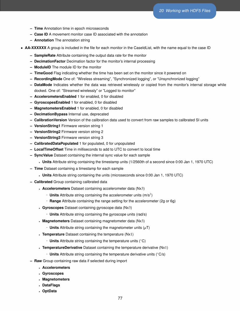
20 Working with HDF5 Files
– Time Annotation time in epoch microseconds
– Case ID A movement monitor case ID associated with the annotation
– Annotation The annotation string
• AA-XXXXXX A group is included in the file for each monitor in the CaseIdList, with the name equal to the case ID
– SampleRate Attribute containing the output data rate for the monitor
– DecimationFactor Decimation factor for the monitor’s internal processing
– ModuleID The module ID for the monitor
– TimeGood Flag indicating whether the time has been set on the monitor since it powered on
– RecordingMode One of: ”Wireless streaming”, ”Synchronized logging”, or ”Unsynchronized logging”
– DataMode Indicates whether the data was retrieved wirelessly or copied from the monitor’s internal storage while
docked. One of: ”Streamed wirelessly” or ”Logged to monitor”
– AccelerometersEnabled 1 for enabled, 0 for disabled
– GyroscopesEnabled 1 for enabled, 0 for disabled
– MagnetometersEnabled 1 for enabled, 0 for disabled
– DecimationBypass Internal use, deprecated
– CalibrationVersion Version of the calibration data used to convert from raw samples to calibrated SI units
– VersionString1 Firmware version string 1
– VersionString2 Firmware version string 2
– VersionString3 Firmware version string 3
– CalibratedDataPopulated 1 for populated, 0 for unpopulated
– LocalTimeOffset Time in milliseconds to add to UTC to convert to local time
– SyncValue Dataset containing the internal sync value for each sample
* Units Attribute string containing the timestamp units (1/2560th of a second since 0:00 Jan 1, 1970 UTC)
– Time Dataset containing a timestamp for each sample
* Units Attribute string containing the units (microseconds since 0:00 Jan 1, 1970 UTC)
– Calibrated Group containing calibrated data
* Accelerometers Dataset containing accelerometer data (Nx3)
· Units Attribute string containing the accelerometer units (m/s2)
· Range Attribute containing the range setting for the accelerometer (2g or 6g)
* Gyroscopes Dataset containing gyroscope data (Nx3)
· Units Attribute string containing the gyroscope units (rad/s)
* Magnetometers Dataset containing magnetometer data (Nx3)
· Units Attribute string containing the magnetometer units (µT)
* Temperature Dataset containing the temperature (Nx1)
· Units Attribute string containing the temperature units (C)
* TemperatureDerivative Dataset containing the temperature derivative (Nx1)
· Units Attribute string containing the temperature derivative units (C/s)
– Raw Group containing raw data if selected during import
* Accelerometers
* Gyroscopes
* Magnetometers
* DataFlags
* OptData
77

20 Working with HDF5 Files
* Temperature
* TemperatureDerivative
20.3.3 Version 1
This version is deprecated. All new files created will use the most recent version.
• Device List Attribute containing a list of monitors present in the file
• File Format Version Attribute containing the file version
• Annotations Table containing annotations
– Time Annotation time in epoch microseconds
– Device ID A movement monitor ID associated with the annotation
– Annotation The annotation string
• Opal xxx/ Group containing information about and data from monitor ID xxx
– Sample Rate Attribute containing the output data rate for the monitor
– Decimation Factor Decimation factor for the monitor’s internal processing
– Time Good Flag indicating whether the monitor has had its time set since turning on
– Decimation Bypass Internal use, deprecated
– Calibration Version Version of the calibration data used to convert from raw samples to calibrated SI units
– Version String1 Firmware version string 1
– Version String2 Firmware version string 2
– Version String3 Firmware version string 3
– Acceleration Dataset containing data from the accelerometers (Nx3)
* Units Attribute string containing the acceleration units (m/s2)
– Angular Velocity Dataset containing data from the gyroscopes (Nx3)
* Units Attribute string containing the angular velocity units (rad/s)
– Magnetic Field Dataset containing data from the magnetometers (Nx3)
* Units Attribute string containing the magnetic field units (a.u.)
– Temperature Dataset containing the temperature of the monitor (Nx1)
* Units Attribute string containing the temperature units (C)
– Temperature Derivative Dataset containing the rate of change of temperature
* Units Attribute string containing the temperature derivative units (C/s)
– Sync Value Dataset containing the internal timestamp of each sample
* Units Attribute string containing the timestamp units (1/2560th of a second since 0:00 Jan 1, 1970 UTC)
* Time Dataset containing the time for each sample in microseconds since 0:00 Jan 1, 1970 UTC
Additional fields present when raw data is also stored:
• Opal XX/
– Calibration Data Attribute containing binary block of calibration data
– Raw File Version Attribute containing the version string of the raw file (if this was converted from a .apdm file instead
of streamed)
78

20 Working with HDF5 Files
– Accelerometers Raw Dataset containing raw accelerometer data (Nx3)
– Gyroscopes Raw Dataset containing raw gyroscope data (Nx3)
– Magnetometers Raw Dataset containing raw magnetometer data (Nx3)
– Data Flags Dataset containing flags used for processing the raw data
– Opt Data Dataset containing several measurements taken at a low data rate
– Temperature Raw Dataset containing lowpass filtered, but uncalibrated temperature data (Nx1)
20.4 Working with HDF 5 in MATLAB
MATLAB contains two high level functions for working with HDF5 files. Additional help and examples are
included in the built in help documentation for these functions.
hdf5info reads the structure of the file and all of the attribute values and returns them in an easy to browse
MATLAB structure.
hdf5read reads a complete dataset or attribute from the HDF5 file.
Additionally, one more high level helper function is included with the APDM movement monitor software. This
function also contains built in help documentation and examples.
hdf5readslab reads a portion of a dataset from the HDF5 file.
20.5 Examples
Below is simple example of loading acceleration data from an APDM movement monitor HDF5 file (version
2 or later) in MATLAB. For version 1 files, the dataset paths simply need to be changed to match the format
listed above.
filename = 'example.h5';
try
vers = hdf5read(filename, '/FileFormatVersion');
catch
try
vers = hdf5read(filename, '/File_Format_Version');
catch
error('Couldn''t determine file format');
end
end
if vers< 2
error('This example only works with version 2 or later of the data file')
end
79

20 Working with HDF5 Files
caseIdList = hdf5read(filename, '/CaseIdList');
groupName = caseIdList(1).data;
accPath = [groupName '/Calibrated/Accelerometers'];
fs = hdf5read(filename, [groupName '/SampleRate']);
fs = double(fs);
acc = hdf5read(filename, accPath)'; %Transposed to make Nx3 in MATLAB
t = (1:size(acc,1))/fs;
figure;
plot(t,acc);
A more complicated example using the flexibility of HDF5 to load and process only part of a data set. This
can be useful when the data set is too large to fit into memory. Care is taken not to attempt to read beyond
the end of the file.
filename = 'example.h5';
try
vers = hdf5read(filename, '/FileFormatVersion');
catch
try
vers = hdf5read(filename, '/File_Format_Version');
catch
error('Couldn''t determine file format');
end
end
if vers < 2
error('This example only works with version 2 or later of the data file')
end
idList = hdf5read(filename, '/CaseIdList');
groupName = idList(1).data;
accPath = [groupName '/Calibrated/Accelerometers'];
fs = hdf5read(filename, [groupName '/SampleRate']);
fs = double(fs);
fhandle = H5F.open(filename, 'H5F_ACC_RDONLY', 'H5P_DEFAULT');
dset = H5D.open(fhandle, [groupName '/Calibrated/Accelerometers'], 'H5P_DEFAULT');
dspace = H5D.get_space(dset);
[ndims, dims] = H5S.get_simple_extent_dims(dspace);
nSamples = dims(1);
nSamplesRead = min(nSamples, 60*fs); %read at most one minute of data
accSegment = hdf5readslab(filename, accPath, [0,0], [nSamplesRead, 3])';
t = (1:nSamplesRead)/fs;
figure;
plot(t,accSegment);
80

20 Working with HDF5 Files
20.6 Notes
• Arrays in MATLAB use the FORTRAN convention of storing them in memory by column then row,
instead of the C convention (used by HDF 5) of row then column. This has the effect of making the
returned arrays transposed from how this document (and many other interfaces to HDF5) claim they
are laid out.
• Older versions of MATLAB (before 2009a) did not support the compression used in Mobility Lab’s HDF
5 files. If you are using one of these older versions, the free h5repack utility available from the HDF
Group can remove the compression. This utility is available at:
http://www.hdfgroup.org/HDF5/release/obtain5.html
The command to repack the file is:h5repack -f NONE example.h5 example_no_compression.h5
81

21 Monitor Reference
21 Monitor Reference
21.1 Charging
A movement monitor charges its internal battery any time it is connected to a docking station. At the optimal
charge rate the movement monitors internal battery will complete its bulk charge (80%-90%) within an hour
for a fully discharged battery. It is recommended that the movement monitor be charged for up to 3 hours to
provide a peak charge to the battery ensuring it has the longest run time and improves battery life.
Warning: Your movement monitor uses a lithium battery. This battery may only be charged over a limited
temperature range. Never attempt to dock or charge your Opal when the temperature experienced can be
outside the range of 0 to 45 degrees Celsius (32 to 113 degrees Fahrenheit). The recommended charging
and docking temperature range is between 5 to 35 degrees Celsius (40 to 95 degrees Fahrenheit).
21.2 Powering Down
If you wish to power down your monitors for storage or travel, dock the monitors you wish to power down
and click on the “Power Off” button in Mobility Lab. After this process is complete, these monitors will power
down when they are undocked. They can be powered back on by re-applying the saved configuration or
re-configuring the system.
21.3 Data Storage
The movement monitors utilize a flash card to store data while logging. This data can be downloaded by
using a docking station to dock the movement monitor. When the movement monitor is docked it finishes up
writing to the internal flash card and then releases it to the docking station. At this time the docking station
indicates to the PC that there is a new read only removable drive to be mounted. Using your file browser
you can navigate to the removable drive and copy the files off of it. The files are in a proprietary raw format
and need to be converted to either a HDF5 or CSV format that will provide data in calibrated SI units. This
conversion happens automatically if Mobility Labis used to import the data. Alternately, there are functions
in the SDK to do this conversion programmatically.
21.4 Cleaning
Cleaning the movement monitors case should be done by wiping the bottom of the case where it contacts
the skin with Rubbing alcohol or other cleaning wipe. If the entire case needs to be cleaned use only an ethyl
alcohol or isopropyl alcohol based wipe. Methyl alcohol should be avoided for cleaning the top since it will
82

21 Monitor Reference
cause degradation of the plastic over time. The movement monitor should not be submerged in any liquids or
subjected to any high temperatures for cleaning. The straps on the monitor can be cleaned by wiping them
down with Rubbing alcohol. Alternatively the straps can be removed and washed separately using mild soap
and water.
21.5 Storage
Storage of the movement monitor should be in a dry static fee location. An anti-static bag or in the supplied
case is recommended. The movement monitor should also not be subjected to any large G forces to prevent
damage or changes to the calibration of the sensors in the monitor. It is recommended for the health of the
battery to to have at least a bulk charge during storage.
21.6 Drivers
Drivers are provided as part of the library distribution and Mobility Lab. The drivers are installed automatically
as part of the Mobility Lab installation process.
21.7 Firmware Updates
Updating the movement monitor firmware should be done using the Mobility Lab software. This process is
detailed in Section 18 of this document.
21.8 Technical Specifications
• The accelerometer range is ±58.8 m/ s2 (6 g) (optionally ±19.6 m/ s2 (2 g)).
• Accelerometers have a typical noise density of 1.3 mm/ s2/√
Hz.
• The X and Y axis gyros have a range of ±34.9 rad/s (2000 dps)
• The Z axis gyro has a range of ±26.8 rad/s (1500 dps)
• The X and Y axis gyros have a typical noise density of 0.81 mrad/ s/√
Hz
• The Z axis gyro have a typical noise density of 2.2 mrad/ s/√
Hz
• Magnetometers have a range of ±6 Gauss
• The magnetometers have a typical noise density is 160 nT/√
Hz
• Positive X is pointing from the monitor toward the connector. Looking top down at the monitor with
positive X pointing away from you, positive Y is pointing left. Z is pointing up out of the top of the case.
Angular velocity sign is defined according to a right hand rule. A counterclockwise rotation about the Z
axis looking from the +Z direction is positive.
83

21 Monitor Reference
21.9 LED Reference
21.9.1 Status Codes and LED Colors/Patterns
The LEDs on the access points and movement monitors provide important information about the operating
state of the hardware, including error statuses. The tables below list the LED patterns associated with these
states and can be useful in troubleshooting issues encountered with the hardware.
21.9.2 Movement Monitor LED Reference
Movement monitors contain a RGB LED capable of outputting a wide array of colors to the user to indicate
its current state. The following colors are used: white (), red (), yellow (), green (), cyan (), blue (),
magenta (), and led off ( ). In the off state the LED will appear as a non illuminated white dot in the corner
of the monitor opposite the docking connector. All LED patterns are output on a repeating cycle which may
vary in period depending on the pattern. In all cases the last color listed will stay constant until the pattern
repeats. For example “ ” will blink yellow twice and then stay off until the pattern repeats.
84

21 Monitor Reference
State LED Pattern
Startup Mode (boot loader)
Startup wait (5 sec) v1.0, bootloader v1
Startup wait (5 sec) v1.1, bootloader v2
Failed to load firmware
Boot loader mode
Firmware Mode
Docked mode (pre-charging – very low battery)
Docked mode (bulk charging – low battery) (fast)
Docked mode (trickle charging – 80-100% charge) (slow)
Docked mode (full charge)
Docked mode (battery error)
Docked mode (wait)
Docked mode (error)
Reset mode
Transitioning into standby or powering off
Hold mode
Run mode (battery level 4, full)
Run mode (battery level 3)
Run mode (battery level 2)
Run mode (battery level 1, low)
Run mode (battery very low)
Run mode (clock unset, battery level 4, full)
Run mode (clock unset, battery level 3)
Run mode (clock unset, battery level 2)
Run mode (clock unset, battery level 1, low)
Run mode (clock unset, battery very low)
Run mode (no sync-lock, battery level 4, full)
Run mode (no sync-lock, battery level 3)
Run mode (no sync-lock, battery level 2)
Run mode (no sync-lock, battery level 1, low)
Run mode (no sync-lock, battery very low)
Run mode (clock unset, no sync-lock, battery level 4, full)
Run mode (clock unset, no sync-lock, battery level 3)
Run mode (clock unset, no sync-lock, battery level 2)
Run mode (clock unset, no sync-lock, battery level 1, low)
Run mode (clock unset, no sync-lock, battery very low)
85

21 Monitor Reference
State LED Pattern
Error Modes
Error mode: default
Error mode: configuration
Error mode: system
Error mode: data buffer
Error mode: SD buffer
Error mode: SD I/O
Card is full
Wireless Streaming Debug LED Modes
Normal
CPU limited
Sync bad
CPU limited, Sync bad
Missed sync > 0
Missed sync > 0, CPU limited
Missed sync > 0, Sync bad
Missed sync > 0, CPU limited, Sync bad
86

21 Monitor Reference
21.10 Technical Drawing
.528
in13
.40m
m
1.90
6in
48.4
0mm
.118
in3m
m.335
in8.
50m
m
1.68
9in
42.9
0mm
.226
in5.
75m
m
.035
in T
HRU
0.89
mm [1.3
0mm
]M
2x0.
4 Th
read
0.
051i
n
1.43
7in
36.5
0mm
.234
in5.
95m
m
1.42
1in
36.1
0mm
.807
in20
.50m
m
.211
in5.
35m
m
.098
in2.
50m
m
APD
M M
onito
r Dim
ensio
ns, V
ersio
n 1.
1C
OM
MEN
TS:
6061
Alu
min
um b
ase
and
PC/A
BS to
pM
ATE
RIA
L:
SCA
LE: 2
:1
Alu
min
um: 0
.000
8" C
lear
Ano
dize
TOLE
RAN
CES
: UN
LESS
OTH
ERW
ISE
SPEC
IFIE
D: .
XX=
.01,
.XXX
= .0
05, A
NG
ULA
R 1.
FINIS
H:
87

22 Access Point Reference
22 Access Point Reference
22.1 Drivers
Drivers are provided as part of the SDK distribution and Mobility Lab.
22.2 Firmware Updates
Updating the movement monitor firmware should be done using the Mobility Lab software.
22.3 Mounting and Placement
The antennas of the access point are located directly behind the black plastic face of the access point. The
access point(s) should be aimed such that this face is in the approximate direction of the area where the
movement monitors will be used.
22.4 Using Multiple Access Points
Having multiple access points is useful when redundancy is needed or when recording from more than 6
Opals. To configure multiple access points, you must have them attached to your computer via USB at the
time of configuration. Additionally, the access points must be linked via RCA cable (a standard stereo cable).
The rest of the configuration is handled automatically.
22.4.1 Redundancy
In some recording environments, it may be difficult to always maintain line of site from your streaming Opals
to the access point. For example, you may have a bend in a hallway, or you may be operating in a large open
space where you are unlikely to receive a reflected signal if the Opal is pointed away from the access point.
In these scenarios, multiple access points can be used to provide better coverage. The streaming Opals will
communicate with whichever access point is providing the stronger signal.
22.4.2 Streaming from more than 6 Opals
Each access point can communicate with up to 6 Opals simultaneously. You can therefore stream from up to
12 Opals with 2 access points, or 24 Opals with 4 access points.
88
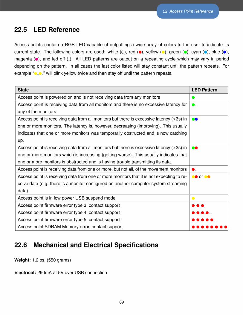
22 Access Point Reference
22.5 LED Reference
Access points contain a RGB LED capable of outputting a wide array of colors to the user to indicate its
current state. The following colors are used: white (), red (), yellow (), green (), cyan (), blue (),
magenta (), and led off ( ). All LED patterns are output on a repeating cycle which may vary in period
depending on the pattern. In all cases the last color listed will stay constant until the pattern repeats. For
example “ ” will blink yellow twice and then stay off until the pattern repeats.
State LED Pattern
Access point is powered on and is not receiving data from any monitors
Access point is receiving data from all monitors and there is no excessive latency for
any of the monitors
Access point is receiving data from all monitors but there is excessive latency (>3s) in
one or more monitors. The latency is, however, decreasing (improving). This usually
indicates that one or more monitors was temporarily obstructed and is now catching
up.
Access point is receiving data from all monitors but there is excessive latency (>3s) in
one or more monitors which is increasing (getting worse). This usually indicates that
one or more monitors is obstructed and is having trouble transmitting its data.
Access point is receiving data from one or more, but not all, of the movement monitors
Access point is receiving data from one or more monitors that it is not expecting to re-
ceive data (e.g. there is a monitor configured on another computer system streaming
data)
or
Access point is in low power USB suspend mode.
Access point firmware error type 3, contact support
Access point firmware error type 4, contact support
Access point firmware error type 5, contact support
Access point SDRAM Memory error, contact support
22.6 Mechanical and Electrical Specifications
Weight: 1.2lbs, (550 grams)
Electrical: 290mA at 5V over USB connection
89

22 Access Point Reference
22.7 Technical Drawing
5.22
7in
132.
76m
m
4.33
1in
110m
m R.41
3in
10.5
0mm
8.32
7in
211.
50m
m
.125
in3.
18m
m
.917
in23
.29m
m
2.35
0in
59.6
9mm
3.08
3in
78.3
0mm
.825
in20
.96m
m
.407
in10
.34m
m
4.16
3in
105.
75m
m
R.18
8in
4.76
mm
1/4-
20 T
appe
d H
ole
3.30
6in
83.9
8mm
.467
in11
.85m
m
1.57
3in
39.9
5mm
1.67
5in
42.5
5mm
APD
M_A
cces
sPoi
ntFI
LE N
AM
E:C
OM
MEN
TS:
6061
Alu
min
um b
ack
& st
and
and
ABS
top
MA
TERI
AL:
SCA
LE: 1
:2
FINIS
H:
TOLE
RAN
CES
: UN
LESS
OTH
ERW
ISE
SPEC
IFIE
D: .
XX=
.01,
.XXX
= .0
05, A
NG
ULA
R 1.
Alu
min
um: 0
.000
8" C
lear
Ano
dize
90

23 Docking Station Reference
23 Docking Station Reference
23.1 Drivers
Drivers are provided as part of the SDK distribution and Mobility Lab.
23.2 Power
• If running a single docking station, it can be powered from:
– a USB cable plugged into a dedicated USB port on your computer
– a USB cable plugged into a a powered USB hub
– a USB cable plugged into a wall adapter (charging only)
– the external AC adapter (charging only)
• If running a chain of 2 or more docking stations:
– For data transfer, both USB and external AC power are required. If a power-related error occurs,
then the docking station will blink yellow until external or power is plugged in.
– if only charging is required, the external AC power must be used
23.3 Mechanical and Electrical Specifications
Weight: 0.2 lbs, (90 grams)
Electrical: 500mA at 5V over USB connection, or 500mA per dock when a chain is supplied by external
power.
91

23 Docking Station Reference
23.4 LED Reference
Docking stations contain a RGB LED capable of outputting a wide array of colors to the user to indicate its
current state. The following colors are used: white (), red (), yellow (), green (), cyan (), blue (),
magenta (), and led off ( ). All LED patterns are output on a repeating cycle which may vary in period
depending on the pattern. In all cases the last color listed will stay constant until the pattern repeats. For
example “ ” will blink yellow twice and then stay off until the pattern repeats.
State LED Pattern
OK
Powered off, USB suspended, or booloader pause
OK, but USB not enumerated
Power problem. Need to plug in external power or USB
power.
Docking in progress
Docked, but SD unavailable to host
SD Card mounting in progress
SD Card mounted and avaliable to host
SD card read-access in progress
USB error
Error
Error: SD card mounting error
Error: in-dock USB hub problem
Firmware error type 4, contact support
Firmware error type 5, contact support
Firmware error type 6, contact support
Bootloader mode
Updating firmware
Hardware Error - DA
Hardware Error - GA
Hardware Error - PA
Hardware Error - UA
92

23 Docking Station Reference
23.5 Technical Drawing
1.
634i
n41
.51m
m
.1
80in
4.57
mm
.5
00in
12.7
0mm
1.
953i
n49
.60m
m
.2
93in
7.45
mm
.2
93in
7.45
mm
1.
480i
n37
.60m
m
1.
033i
n26
.25m
m
.3
64in
9.25
mm
2.
067i
n52
.50m
m
2.
539i
n64
.50m
m
APD
M_D
ock
FILE
NA
ME:
CO
MM
ENTS
:
6061
Alu
min
um p
late
and
ABS
top
& b
otto
mM
ATE
RIA
L:
SCA
LE: 1
:1TO
LERA
NC
ES: U
NLE
SS O
THER
WIS
E SP
ECIF
IED
: .XX
= .0
1, .X
XX=
.005
, AN
GUL
AR
1.
Alu
min
um: 0
.000
8" C
lear
Ano
dize
FINIS
H:
93

24 Troubleshooting
24 TroubleshootingAPDM is pleased to assist you with any questions you may have about our software or about the use of the
technology for your application.
Please contact us at:
web: support.apdm.com
email: [email protected]
telephone: 888-988-APDM (2736)
Opal-Users Mailing List: https://mail.apdm.com/mailman/listinfo/opal-users
94

References
References[1] M. Mancini, C. Zampieri, P. Carlson-Kuhta, L. Chiari, and F. B. Horak, Anticipatory postural adjustments
prior to step initiation are hypometric in untreated parkinson’s disease: an accelerometer-based ap-
proach., Eur J Neurol 16 (2009), no. 9, 1028–1034.
[2] Martina Mancini, Arash Salarian, Patricia Carlson-Kuhta, Cris Zampieri, Laurie King, Lorenzo Chiari, and
Fay B Horak, Isway: a sensitive, valid and reliable measure of postural control., J Neuroeng Rehabil 9
(2012), no. 1, 59 (eng).
[3] Meir Plotnik, Nir Giladi, and Jeffrey M Hausdorff, A new measure for quantifying the bilateral coordination
of human gait: effects of aging and parkinson’s disease., Exp Brain Res 181 (2007), no. 4, 561–570
(eng).
[4] Arash Salarian, Fay B Horak, Cris Zampieri, Patricia Carlson-Kuhta, John G Nutt, and Kamiar Aminian,
itug, a sensitive and reliable measure of mobility., IEEE Trans Neural Syst Rehabil Eng 18 (2010), no. 3,
303–310.
[5] Arash Salarian, Heike Russmann, Franois J G Vingerhoets, Pierre R Burkhard, and Kamiar Aminian,
Ambulatory monitoring of physical activities in patients with parkinson’s disease., IEEE Trans Biomed
Eng 54 (2007), no. 12, 2296–2299.
[6] Arash Salarian, Heike Russmann, Franois J G Vingerhoets, Catherine Dehollain, Yves Blanc, Pierre R
Burkhard, and Kamiar Aminian, Gait assessment in parkinson’s disease: toward an ambulatory system
for long-term monitoring., IEEE Trans Biomed Eng 51 (2004), no. 8, 1434–1443.
[7] A. Sant’Anna, A. Salarian, and N. Wickstrom, A new measure of movement symmetry in early parkinson’s
disease patients using symbolic processing of inertial sensor data, IEEE Transactions on Biomedical
Engineering 58 (2011), no. 7, 2127–2135.
95