Embed Size (px)
Citation preview
Mobile Plate Hunter-900
Operations Center User’s Manual
Publication Number MPH-900-OCUM • Version 2.0 • December 2009
- 17015 -
ELSAG North America Operations Center User’s Manual
MPH-900-OCUM Page 2 Version 2.0 • December 2009
© 2009 ELSAG North America, LLC — All Rights Reserved. The copyright laws of the United States and other countries specifically protect this material in its entirety. It may not be reproduced, distributed, or altered in any way without the expressed written consent of ELSAG North America.
Under copyright laws, neither the documentation, nor any associated software may be copied, photo-copied, reproduced, translated, or reduced to any electronic medium of machine readable form, in whole or in part, without the written consent of ELSAG North America.
Notice Every effort was made to ensure that the information in this document was accurate at the time of printing. However, all information is subject to change without notice.
Trademark Information EOC™ is a trademark of ELSAG North America, LLC FPH™900 is a trademark of ELSAG North America, LLC MPH™900 is a trademark of ELSAG North America, LLC
ELSAG North America Contact Information To contact us, please refer to the information below:
Corporate Headquarters — U.S.A. 412 Clock Tower Commons
Brewster, NY 10509 Telephone: 866-9-MPH-900 (866-967-4900)
OR Telephone: 845-278-5425 Facsimile: 845-278-5428
Technology and Manufacturing
205 H Creek Ridge Road Greensboro, NC 27406
Telephone: 336-379-7135 Facsimile: 336-379-7164
Technical Support Department Technical Support Department email: [email protected]
Visit us on the Internet www.elsagnorthamerica.com
OR www.elsagna.com
Ordering Information The ordering number for this publication is Publication Number MPH-900-OCUM • Version 2.0. To order this document, contact ELSAG North America.
IMPORTANT: If you are in possession of a printed or electronic version of this manual, be aware that it may not be the current version. To ensure that you are using the most up-to-date version of this manual, please contact ELSAG North America.
- 17016 -
ELSAG North America Operations Center User’s Manual
MPH-900-OCUM Page 3 Version 2.0 • December 2009
Table of Contents
Chapter 1 — Preface and General Information ........................................................................................ 9
.... About This User’s Manual/Purpose ................................................................................................. 9
.... Disclaimer ........................................................................................................................................ 9
.... Revision Information ........................................................................................................................ 9
.... Software, Database and Manual Versions and Revisions ............................................................. 10
Software and Database Versions ............................................................................................ 10
Manual Versions ...................................................................................................................... 10
Software and Manual Versions and Revisions ........................................................................ 11
.... Change Management ..................................................................................................................... 11
.... Graphic User Interface (GUI) ......................................................................................................... 11
.... ELSAG North America Terminology, Acronyms, and Terms ......................................................... 12
Chapter 2 — System Overview ................................................................................................................ 13
.... Introduction .................................................................................................................................... 13
.... System Architecture ....................................................................................................................... 13
Chapter 3 — Login Procedure and Main Menu Overview ..................................................................... 14
.... Introduction .................................................................................................................................... 14
Cautions Concerning Passwords and Password Expiration ................................................... 15
Password Expiration ................................................................................................................ 16
.... First Time Users/Change Password .............................................................................................. 18
Password Parameters and Requirements ............................................................................... 18
.... Login Error ..................................................................................................................................... 19
.... Logging in to System ...................................................................................................................... 19
.... Main Menu or “Home” Screen Overview ........................................................................................ 19
.... Main Menu Permissions ................................................................................................................. 21
Logout Feature ........................................................................................................................ 22
System Clock ........................................................................................................................... 22
Alarms Count Window ............................................................................................................. 22
Home Link, User Name Display, and Change Password ........................................................ 23
.... Main Menu or “Home” Screen Reports .......................................................................................... 24
Car Download Status Report ................................................................................................... 25
Import Status Report ............................................................................................................... 26
Statistics Report ...................................................................................................................... 26
- 17017 -
ELSAG North America Operations Center User’s Manual
MPH-900-OCUM Page 4 Version 2.0 • December 2009
.... Session Time Out ........................................................................................................................... 27
Chapter 4 — Diagnostic Features ........................................................................................................... 28
.... Introduction .................................................................................................................................... 28
.... Manual Trouble Insertion ............................................................................................................... 28
.... Trouble Management (Query Troubles) ......................................................................................... 29
.... Diagnostics Email Address ............................................................................................................ 30
.... Diagnostic Applet ........................................................................................................................... 32
Policy File ................................................................................................................................ 32
Virtual Machine ........................................................................................................................ 33
Start Diagnostic ....................................................................................................................... 33
Chapter 5 — Query/Statistics .................................................................................................................. 36
.... Introduction .................................................................................................................................... 36
.... Query Reads .................................................................................................................................. 36
Map Based Searches .............................................................................................................. 43
Cartographic Tool ............................................................................................................. 43
Geographic Coordinates .................................................................................................. 43
Query Results Tools and Functions ........................................................................................ 44
File Export ........................................................................................................................ 44
Export Html File ................................................................................................................ 44
Show All On Map ............................................................................................................. 45
.... Alarm Validation ............................................................................................................................. 46
.... Mission Replay ............................................................................................................................... 49
.... Delete Reads ................................................................................................................................. 50
.... Statistics ......................................................................................................................................... 52
Chapter 6 — Hot List Management ......................................................................................................... 54
.... Introduction .................................................................................................................................... 54
.... Export Hot List ................................................................................................................................ 54
.... Insert Delete HL (Hot List).............................................................................................................. 55
.... Show Hot List ................................................................................................................................. 57
.... Hot List Import Status ..................................................................................................................... 58
.... Post Hit Analysis ............................................................................................................................ 60
.... Hot List Import Status History ........................................................................................................ 61
.... Import Extern(al) HL (Hot List) ....................................................................................................... 63
.... Import Local HL (Hot List) .............................................................................................................. 63
- 17018 -
ELSAG North America Operations Center User’s Manual
MPH-900-OCUM Page 5 Version 2.0 • December 2009
.... Hot List File Name and Format ...................................................................................................... 64
Chapter 7 — User Configuration ............................................................................................................. 65
.... Introduction .................................................................................................................................... 65
.... Modify User .................................................................................................................................... 65
.... Users Log ....................................................................................................................................... 68
.... Add User ........................................................................................................................................ 70
Chapter 8 — Software Management ........................................................................................................ 72
.... Introduction .................................................................................................................................... 72
.... Activate Camera SW ...................................................................................................................... 72
.... Activate Remote SW ...................................................................................................................... 72
.... Import SW Camera ........................................................................................................................ 73
.... Import SW Peripheral ..................................................................................................................... 73
Chapter 9 — Data Mining .......................................................................................................................... 74
.... Introduction .................................................................................................................................... 74
.... Cross Search ................................................................................................................................. 74
Cross Search Step 1 ............................................................................................................... 74
Map Based Searches ....................................................................................................... 75
Cross Search Step 2 ............................................................................................................... 76
Map Based Searches ....................................................................................................... 76
Cross Search Step 3 ............................................................................................................... 76
.... Nested & Convoy Search ............................................................................................................... 77
Map Based Searches ....................................................................................................... 78
Chapter 10 — Parameters Management ................................................................................................. 79
.... Introduction .................................................................................................................................... 79
.... Parameters Management .............................................................................................................. 79
.... Email Address Alarms .................................................................................................................... 81
Add New Email Address Alarms.............................................................................................. 81
Modify Email Address Alarms .................................................................................................. 82
Chapter 11 — Roles Management ........................................................................................................... 83
.... Introduction .................................................................................................................................... 83
.... Add Role ........................................................................................................................................ 83
.... Modify Roles Menu ........................................................................................................................ 84
.... Add/Delete Functions ..................................................................................................................... 85
- 17019 -
ELSAG North America Operations Center User’s Manual
MPH-900-OCUM Page 6 Version 2.0 • December 2009
List of Figures Figure 1 — Manual Version Information ..................................................................................................... 10
Figure 2 — System Architecture (Shown Using Wi-Fi Connectivity) .......................................................... 13
Figure 3 — Login Screen ............................................................................................................................ 14
Figure 4 — Password Expiration Notification .............................................................................................. 16
Figure 5 — Password Expiration Reminder ................................................................................................ 16
Figure 6 — Password and Login Flow Chart .............................................................................................. 17
Figure 7 — Login Procedure ....................................................................................................................... 18
Figure 8 — Error Message Shown if the Two Password Entries Do Not Match ......................................... 19
Figure 9 — Login Error Message ................................................................................................................ 19
Figure 10 — Menu Options Schematic Diagram ........................................................................................ 20
Figure 11 — Logout Feature and Help Button ............................................................................................ 22
Figure 12 — System Clock ......................................................................................................................... 22
Figure 13 — Alarms Count Window ............................................................................................................ 23
Figure 14 — Home Link and User Name Display ....................................................................................... 23
Figure 15 — Main Menu or “Home” Screen ................................................................................................ 24
Figure 16 — Session Time Out Message ................................................................................................... 27
Figure 17 — Manual Trouble Insertion Screen ........................................................................................... 28
Figure 18 — Query Troubles Screen .......................................................................................................... 29
Figure 19 — Trouble Management Report ................................................................................................. 30
Figure 20 — Exporting a Trouble Management Report .............................................................................. 30
Figure 21 — Diagnostics Email Address Add New Screen ........................................................................ 31
Figure 22 — Diagnostics Email Address Delete Screen ............................................................................ 31
Figure 23 — Deletion Confirmation Dialog Box .......................................................................................... 31
Figure 24 — Diagnostic Applet Screen ....................................................................................................... 32
Figure 25 — Policy File Download Dialog Box ........................................................................................... 32
Figure 26 — Virtual Machine Identification Screen ..................................................................................... 33
Figure 27 — Java Logo ............................................................................................................................... 33
Figure 28 — Operational Center Diagnostic Dialog Box ............................................................................ 34
Figure 29 — System Status Report ............................................................................................................ 34
Figure 30 — Car Download Status ............................................................................................................. 35
Figure 31 — Errors Table ............................................................................................................................ 35
Figure 32 — Query Reads Screen .............................................................................................................. 36
Figure 33 — Sample Query Results Screen ............................................................................................... 37
Figure 34 — Sample Enlarged Thumbnail .................................................................................................. 38
- 17020 -
ELSAG North America Operations Center User’s Manual
MPH-900-OCUM Page 7 Version 2.0 • December 2009
Figure 35 — Vehicle Report ........................................................................................................................ 39
Figure 36 — Image Analyzer Download Window ....................................................................................... 40
Figure 37 — Image Examination Window Controls .................................................................................... 40
Figure 38 — Select Destination File Window .............................................................................................. 41
Figure 39 — Read Map Location Screen .................................................................................................... 42
Figure 40 — Cartographic Tool/Select Geographic Area Example ............................................................ 43
Figure 41 — Query Results Tools ............................................................................................................... 44
Figure 42 — Sample File Export Report ..................................................................................................... 44
Figure 43 — Export Html File Save/Open Window ..................................................................................... 45
Figure 44 — Sample Show All On Map Report .......................................................................................... 45
Figure 45 — Alarm Validation Screen ......................................................................................................... 46
Figure 46 — Sample Alarm Results Query Screen .................................................................................... 47
Figure 47 — Validation Session Screen ..................................................................................................... 48
Figure 48 — Mission Replay Screen .......................................................................................................... 49
Figure 49 — Mission Replay Query Results ............................................................................................... 49
Figure 50 — Sample Mission Replay Screen ............................................................................................. 50
Figure 51 — Query Reads to be Deleted Screen ....................................................................................... 51
Figure 52 — Sample Delete Read Query Results ...................................................................................... 51
Figure 53 — Statistics Screen..................................................................................................................... 52
Figure 54 — Sample Statistic Report .......................................................................................................... 52
Figure 55 — Sample Bar Graph ................................................................................................................. 53
Figure 56 — Statistics File Download ......................................................................................................... 53
Figure 57 — Export Hot List Screen ........................................................................................................... 54
Figure 58 — Export Hot List File Download Dialog Box ............................................................................. 55
Figure 59 — Insert Delete HL (Hot List) — Insert Hot List Screen ............................................................. 55
Figure 60 — Insert Delete HL (Hot List) — Delete Hot List Screen ............................................................ 56
Figure 61 — Post-hit Analysis Result Screen ............................................................................................. 56
Figure 62 — Confirmation of a Successfully Hot List Entry Deletion .......................................................... 57
Figure 63 — Query Hot List Screen ............................................................................................................ 58
Figure 64 — Result Query in Hot List Message and Report ....................................................................... 58
Figure 65 — Hot List Import Status Screen ................................................................................................ 59
Figure 66 — Post Hit Analysis Report ........................................................................................................ 60
Figure 67 — No Reads Found Message .................................................................................................... 60
Figure 68 — Import Status Hot List Screen ................................................................................................ 61
Figure 69 — Import Query Result Report ................................................................................................... 62
- 17021 -
ELSAG North America Operations Center User’s Manual
MPH-900-OCUM Page 8 Version 2.0 • December 2009
Figure 70 — Import Extern(al) HL (Hot List) Screen ................................................................................... 63
Figure 71 — Import Local HL (Hot List) Screen .......................................................................................... 63
Figure 72 — Modify User Screen ................................................................................................................ 65
Figure 73 — Sample of a User to be Modified ............................................................................................ 66
Figure 74 — User Successfully Modified Message .................................................................................... 67
Figure 75 — Users Log Screen .................................................................................................................. 68
Figure 76 — Log Information Report .......................................................................................................... 69
Figure 77 — Exported Log Information Report ........................................................................................... 69
Figure 78 — Add New User Screen ............................................................................................................ 70
Figure 79 — User Created Successfully Message ..................................................................................... 71
Figure 80 — Activate New Camera Software Version Screen ................................................................... 72
Figure 81 — Activate New Software Version Screen ................................................................................. 72
Figure 82 — Import SW Camera Screen .................................................................................................... 73
Figure 83 — Import SW Peripheral Screen ................................................................................................ 73
Figure 84 — Cross Search Step 1 Screen .................................................................................................. 75
Figure 85 — Cross Search Step 3 Screen .................................................................................................. 77
Figure 86 — Nested & Convoy Search Query Reads Screen .................................................................... 78
Figure 87 — Change Parameters Screen ................................................................................................... 79
Figure 88 — Parameters Selection Window ............................................................................................... 80
Figure 89 — Email Address Alarms Screen (Add New) ............................................................................. 81
Figure 90 — Email Address Alarms Screen (Modify) ................................................................................. 82
Figure 91 — Create New Role Screen ....................................................................................................... 83
Figure 92 — Create New Role Example ..................................................................................................... 83
Figure 93 — Modify Roles Menu Screen .................................................................................................... 84
Figure 94 — Modify Roles (User Example) ................................................................................................ 84
List of Tables Table A — Manual Revision Information (English Version) .......................................................................... 9
Table B — Required Configuration of the OP-Center PC (Minimum)......................................................... 11
Table C — Main Menu Permissions by Category ....................................................................................... 21
Table D — Car Download Status Report .................................................................................................... 25
Table E — Import Status Report ................................................................................................................. 26
Table F — Statistics Report ........................................................................................................................ 26
Table G — Hot List Import Status Report ................................................................................................... 59
- 17022 -
MPH-900-OCUM Page 9 Version 2.0 • December 2009
Chapter 1 — Preface and General
Information
About This User’s Manual/Purpose
This user’s manual contains information about the ELSAG North America Operations Center System. It covers the various parameters of the application including instructions for daily operation of the system. The intended audiences for this manual include ELSAG North America’s customers’ general operating personnel, system administrators, authorized ELSAG North America clients and business partners, and Software Product Evaluators. It is particularly intended for personnel who are responsible for day-to-day operation of the system. In addition and as is appropriate, this manual may be used in customer training.
Information in this manual includes the following:
Available functions
Step-by-step system operation, and
System messages.
IMPORTANT: The information that pertains to basic level users is contained in the Query/Statistics Chapter that begins on Page 36.
Disclaimer
IMPORTANT: This manual contains information about the Operations Center System manufactured by ELSAG North America. The manner and scope of the material presented is reasonable and customary for this type of application. No representations or warranties are made as to the accuracy or completeness of the information contained herein.
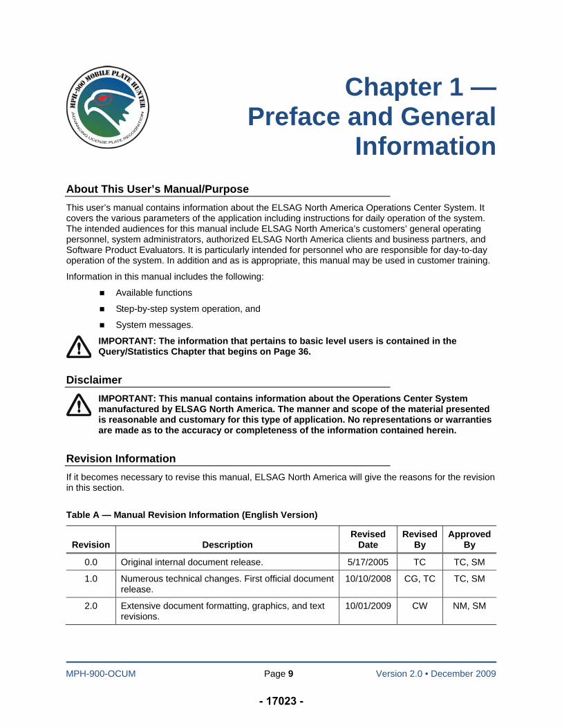
Revision Information
If it becomes necessary to revise this manual, ELSAG North America will give the reasons for the revision in this section.
Table A — Manual Revision Information (English Version)
Revision
Description
Revised Date
Revised By
ApprovedBy
0.0 Original internal document release. 5/17/2005 TC TC, SM
1.0 Numerous technical changes. First official document release.
10/10/2008 CG, TC TC, SM
2.0 Extensive document formatting, graphics, and text revisions.
10/01/2009 CW NM, SM
- 17023 -
ELSAG North America Operations Center User’s Manual
MPH-900-OCUM Page 10 Version 2.0 • December 2009
Software, Database and Manual Versions and Revisions
Software and Database Versions
The user can establish their current software version from the Web site’s Main “Login” screen by clicking on “Help.” The information supplied includes the current versions of the following:
OCRS (Operation Center for Reading Systems)
OCW (Operation Center Web Application), and
OCD (Operation Center Database).
From the “Help” screen, a copy of the latest User Manual is also available by clicking on the “User Manual” link. After clicking on the link, a Portable Document Format (PDF) version of the manual appears. The user has the options of either printing the manual or saving the file for later use. To escape from this screen the user must once again click “Home” button to return to the Main Menu or “Home” Screen OR click “Logout” to return to the “Login” screen.
Manual Versions
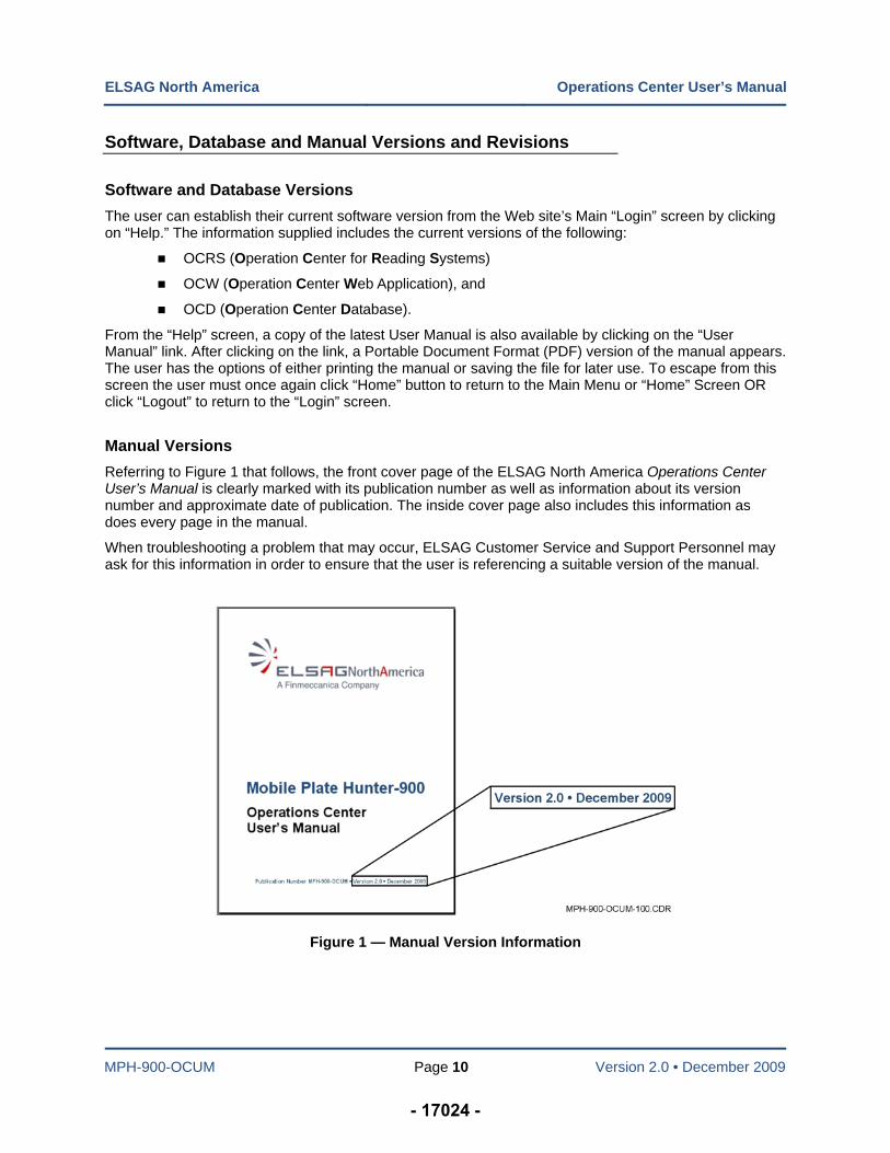
Referring to Figure 1 that follows, the front cover page of the ELSAG North America Operations Center User’s Manual is clearly marked with its publication number as well as information about its version number and approximate date of publication. The inside cover page also includes this information as does every page in the manual.
When troubleshooting a problem that may occur, ELSAG Customer Service and Support Personnel may ask for this information in order to ensure that the user is referencing a suitable version of the manual.
Figure 1 — Manual Version Information
- 17024 -
ELSAG North America Operations Center User’s Manual
MPH-900-OCUM Page 11 Version 2.0 • December 2009
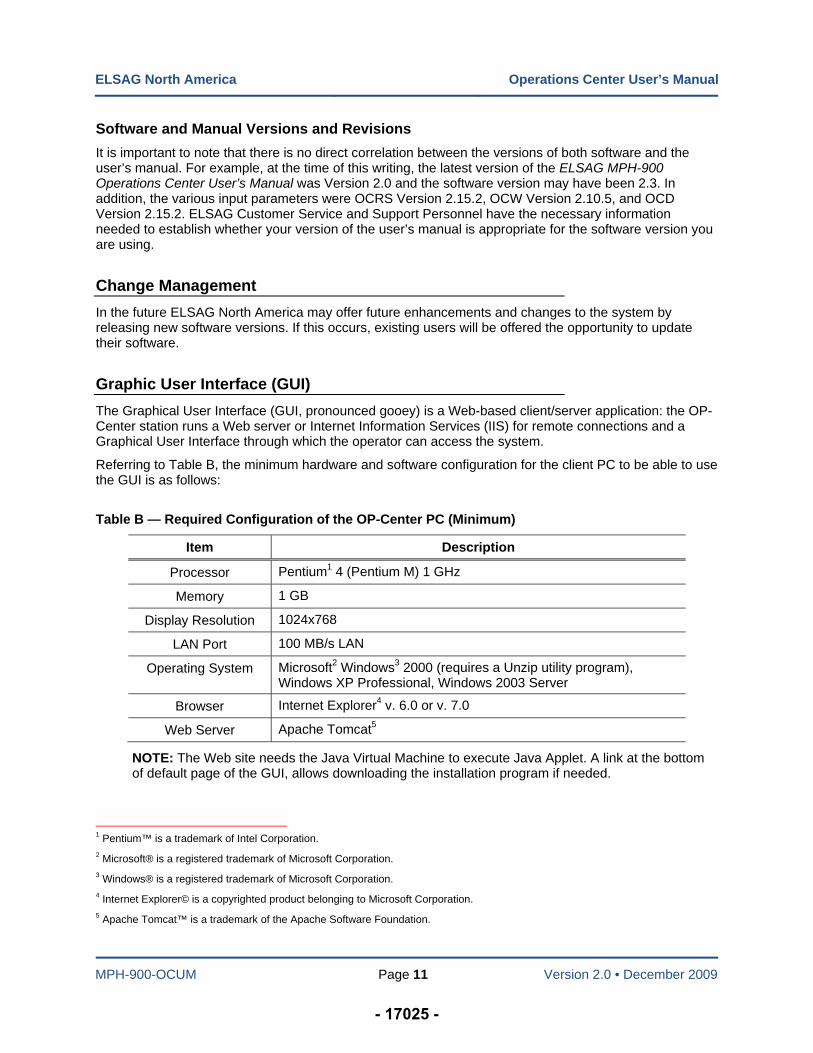
Software and Manual Versions and Revisions
It is important to note that there is no direct correlation between the versions of both software and the user’s manual. For example, at the time of this writing, the latest version of the ELSAG MPH-900 Operations Center User’s Manual was Version 2.0 and the software version may have been 2.3. In addition, the various input parameters were OCRS Version 2.15.2, OCW Version 2.10.5, and OCD Version 2.15.2. ELSAG Customer Service and Support Personnel have the necessary information needed to establish whether your version of the user’s manual is appropriate for the software version you are using.
Change Management
In the future ELSAG North America may offer future enhancements and changes to the system by releasing new software versions. If this occurs, existing users will be offered the opportunity to update their software.
Graphic User Interface (GUI)
The Graphical User Interface (GUI, pronounced gooey) is a Web-based client/server application: the OP-Center station runs a Web server or Internet Information Services (IIS) for remote connections and a Graphical User Interface through which the operator can access the system.
Referring to Table B, the minimum hardware and software configuration for the client PC to be able to use the GUI is as follows:
Table B — Required Configuration of the OP-Center PC (Minimum)
Item Description
Processor Pentium1 4 (Pentium M) 1 GHz
Memory 1 GB
Display Resolution 1024x768
LAN Port 100 MB/s LAN
Operating System Microsoft2 Windows3 2000 (requires a Unzip utility program), Windows XP Professional, Windows 2003 Server
Browser Internet Explorer4 v. 6.0 or v. 7.0
Web Server Apache Tomcat5
NOTE: The Web site needs the Java Virtual Machine to execute Java Applet. A link at the bottom of default page of the GUI, allows downloading the installation program if needed.
1 Pentium™ is a trademark of Intel Corporation.
2 Microsoft® is a registered trademark of Microsoft Corporation.
3 Windows® is a registered trademark of Microsoft Corporation.
4 Internet Explorer© is a copyrighted product belonging to Microsoft Corporation.
5 Apache Tomcat™ is a trademark of the Apache Software Foundation.
- 17025 -
ELSAG North America Operations Center User’s Manual
MPH-900-OCUM Page 12 Version 2.0 • December 2009
The GUI application is hosted on the Web server. We can have more than GUI PC on the network since PCs can use Internet Explorer both to access the application and to monitor, control, and manage the system. These operations are described in detail later in this manual.
Access to system functions is restricted and controlled through the “Roles Management” tool. Different user profiles specify permitted operations for classes of users. They are as follows:
Maintenance
System Administration
User Administration
Manage Alarms, and
User.
Although this manual covers all facets of the system as they are available to a System Administrator, individual users without the required permissions may not be able to access certain functions and features. Details on the characteristics of other profiles are given later in this manual.
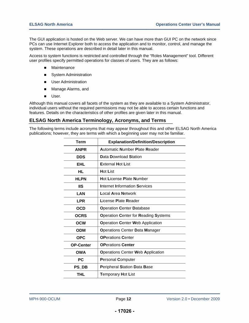
ELSAG North America Terminology, Acronyms, and Terms
The following terms include acronyms that may appear throughout this and other ELSAG North America publications; however, they are terms with which a beginning user may not be familiar.
Term Explanation/Definition/Description
ANPR Automatic Number Plate Reader
DDS Data Download Station
EHL External Hot List
HL Hot List
HLPN Hot License Plate Number
IIS Internet Information Services
LAN Local Area Network
LPR License Plate Reader
OCD Operation Center Database
OCRS Operation Center for Reading Systems
OCW Operation Center Web Application
ODM Operations Center Data Manager
OPC OPerations Center
OP-Center OPerations Center
OWA Operations Center Web Application
PC Personal Computer
PS_DB Peripheral Station Data Base
THL Temporary Hot List
- 17026 -
MPH-900-OCUM Page 13 Version 2.0 • December 2009
Chapter 2 — System Overview
Introduction
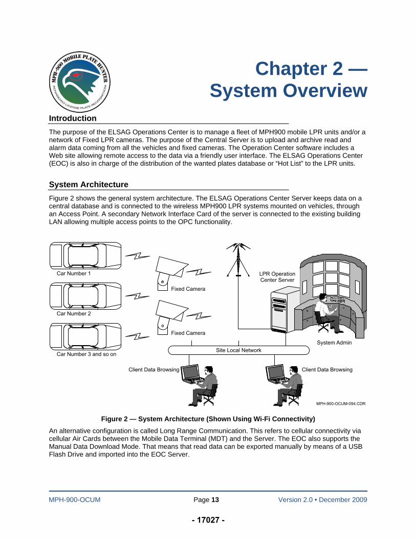
The purpose of the ELSAG Operations Center is to manage a fleet of MPH900 mobile LPR units and/or a network of Fixed LPR cameras. The purpose of the Central Server is to upload and archive read and alarm data coming from all the vehicles and fixed cameras. The Operation Center software includes a Web site allowing remote access to the data via a friendly user interface. The ELSAG Operations Center (EOC) is also in charge of the distribution of the wanted plates database or “Hot List” to the LPR units.
System Architecture
Figure 2 shows the general system architecture. The ELSAG Operations Center Server keeps data on a central database and is connected to the wireless MPH900 LPR systems mounted on vehicles, through an Access Point. A secondary Network Interface Card of the server is connected to the existing building LAN allowing multiple access points to the OPC functionality.
Figure 2 — System Architecture (Shown Using Wi-Fi Connectivity)
An alternative configuration is called Long Range Communication. This refers to cellular connectivity via cellular Air Cards between the Mobile Data Terminal (MDT) and the Server. The EOC also supports the Manual Data Download Mode. That means that read data can be exported manually by means of a USB Flash Drive and imported into the EOC Server.
- 17027 -
MPH-900-OCUM Page 14 Version 2.0 • December 2009
Chapter 3 — Login Procedure and Main Menu Overview
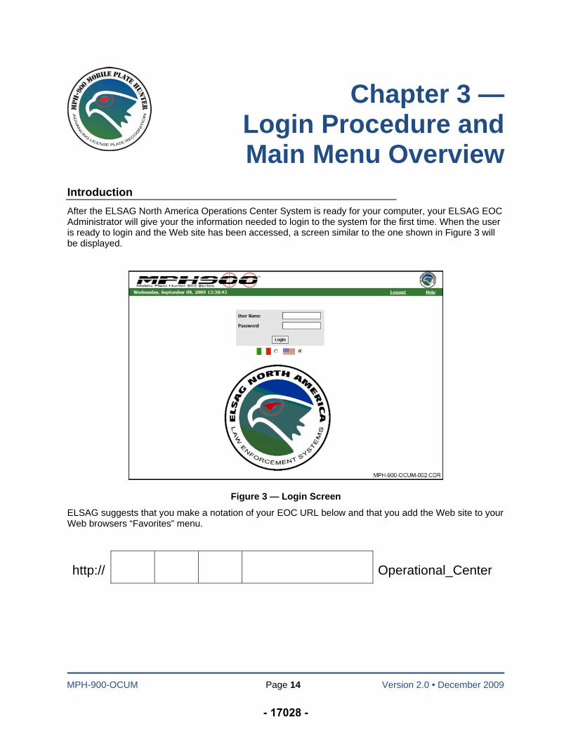
Introduction
After the ELSAG North America Operations Center System is ready for your computer, your ELSAG EOC Administrator will give your the information needed to login to the system for the first time. When the user is ready to login and the Web site has been accessed, a screen similar to the one shown in Figure 3 will be displayed.
Figure 3 — Login Screen
ELSAG suggests that you make a notation of your EOC URL below and that you add the Web site to your Web browsers “Favorites” menu.
http:// Operational_Center
- 17028 -
ELSAG North America Operations Center User’s Manual
MPH-900-OCUM Page 15 Version 2.0 • December 2009
Cautions Concerning Passwords and Password Expiration
The system requires that each user change their password when first accessing the system and every 30 days thereafter. When a password has been used for 15 days, the system will prompt the user to change their password soon and within the next 15-day period. At the end of the 30-day cycle (15 days plus 15 days), the system will attempt to force the user to change the password.
IMPORTANT: After 15 days of prompts for the user to change their password, the system will allow lock out the user and it will be necessary for your ELSAG EOC Administrator to re-enable the account. Refer to the Password and Login Flow Chart shown in Figure 6.
IMPORTANT: Whenever a user attempts to login only five attempts can be made. After the fifth attempt, the system will lock out the user. If this occurs, it will be necessary for your ELSAG EOC Administrator to re-enable the account for the user. Refer to the Password and Login Flow Chart shown in Figure 6.
IMPORTANT: If the user has not accessed the system until after a 30-day period has expired, such as in the case of the user having been on vacation, the system will lock out the user and it is no longer possible for the user to change the password. If this occurs, it will be necessary for your ELSAG EOC Administrator to re-enable the account for the user. Refer to the Password and Login Flow Chart shown in Figure 6. There is currently no way for the local System Administrator to change the password expiration period.
There are two time intervals affecting the EOC Login procedure and Users Management: If a user does not Login for more than X days, his Login is automatically disabled, and the password expires after 30 days (default value).
The parameter that controls the password expiration is included in the TOMCAT properties file found in the following path:
\Program Files\Apache Group\Tomcat 4.1\webapps\ Operational_Center\WEB-INF\classes\operational_center\properties
This is the location where a change can be made. The value is expressed in minutes. For example 86400 means two months. The default is 43200 or one month.
To modify the time interval after which the Login expires, the user should open the database, select the PARAMETER table and modify the parameter LAST_LOGIN_DURATION_DAYS. The parameter is expressed in Days. The maximum is 365 days and do NOT pass this limit. Then restart the Tomcat service to activate the change.
To enable a Disabled User, login as User Administrator (this is the minimum level of privilege required). The open the User Config Menu, select Modify User, and check the ENABLE radio button.
- 17029 -
ELSAG North America Operations Center User’s Manual
MPH-900-OCUM Page 16 Version 2.0 • December 2009
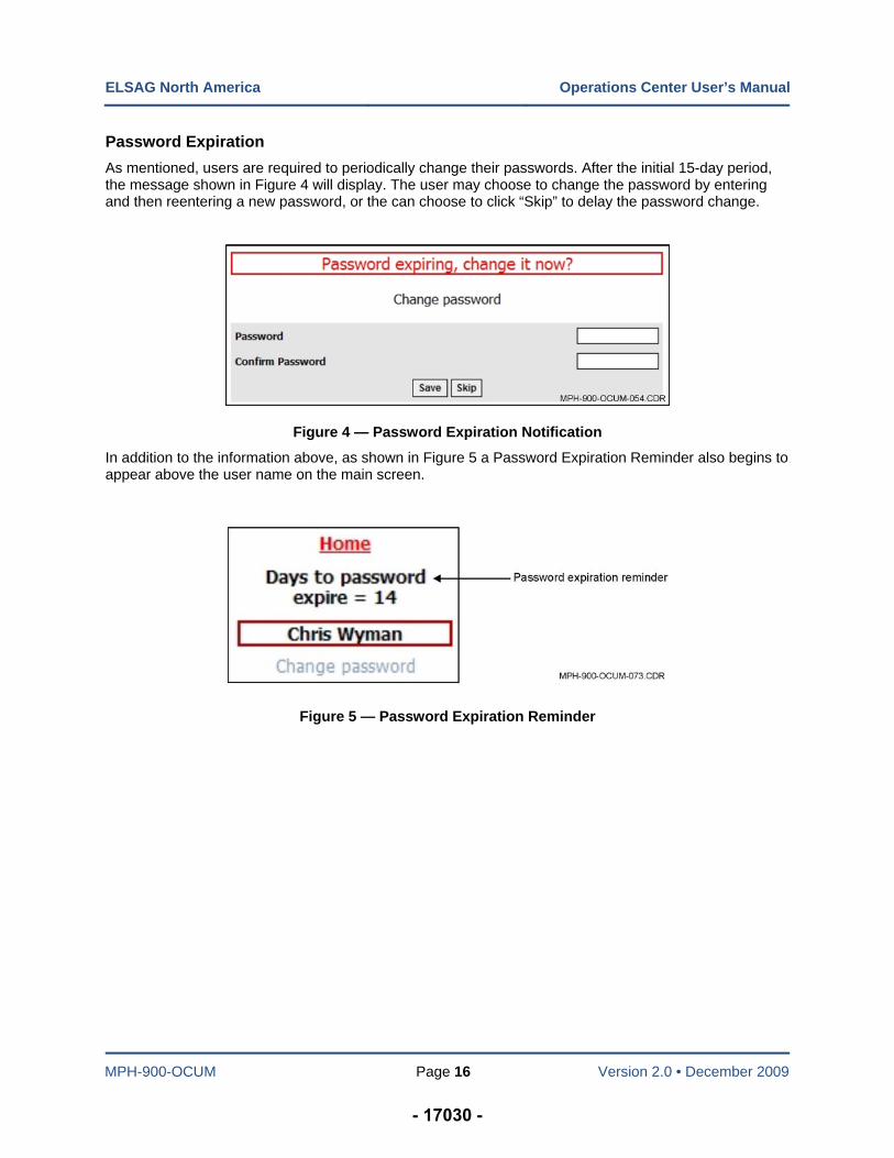
Password Expiration
As mentioned, users are required to periodically change their passwords. After the initial 15-day period, the message shown in Figure 4 will display. The user may choose to change the password by entering and then reentering a new password, or the can choose to click “Skip” to delay the password change.
Figure 4 — Password Expiration Notification
In addition to the information above, as shown in Figure 5 a Password Expiration Reminder also begins to appear above the user name on the main screen.
Figure 5 — Password Expiration Reminder
- 17030 -
ELSAG North America Operations Center User’s Manual
MPH-900-OCUM Page 17 Version 2.0 • December 2009
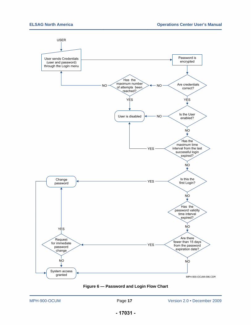
Figure 6 — Password and Login Flow Chart
- 17031 -
ELSAG North America Operations Center User’s Manual
MPH-900-OCUM Page 18 Version 2.0 • December 2009
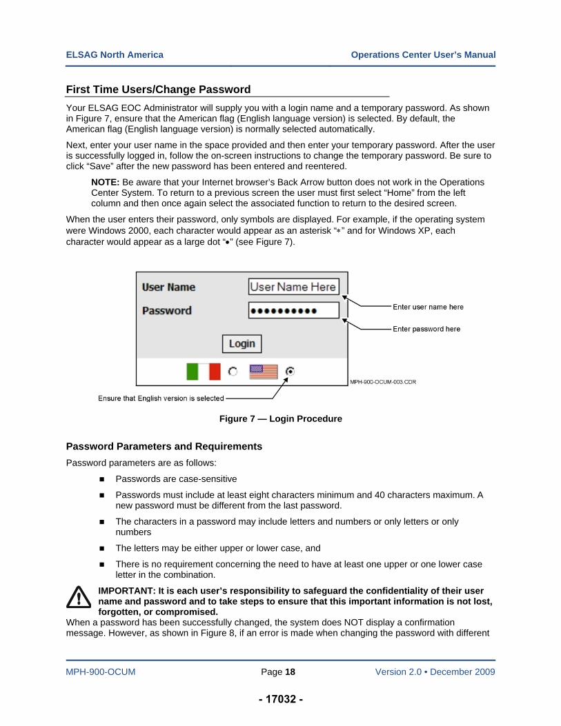
First Time Users/Change Password
Your ELSAG EOC Administrator will supply you with a login name and a temporary password. As shown in Figure 7, ensure that the American flag (English language version) is selected. By default, the American flag (English language version) is normally selected automatically.
Next, enter your user name in the space provided and then enter your temporary password. After the user is successfully logged in, follow the on-screen instructions to change the temporary password. Be sure to click “Save” after the new password has been entered and reentered.
NOTE: Be aware that your Internet browser’s Back Arrow button does not work in the Operations Center System. To return to a previous screen the user must first select “Home” from the left column and then once again select the associated function to return to the desired screen.
When the user enters their password, only symbols are displayed. For example, if the operating system were Windows 2000, each character would appear as an asterisk “” and for Windows XP, each character would appear as a large dot “” (see Figure 7).
Figure 7 — Login Procedure
Password Parameters and Requirements
Password parameters are as follows:
Passwords are case-sensitive
Passwords must include at least eight characters minimum and 40 characters maximum. A new password must be different from the last password.
The characters in a password may include letters and numbers or only letters or only numbers
The letters may be either upper or lower case, and
There is no requirement concerning the need to have at least one upper or one lower case letter in the combination.
IMPORTANT: It is each user’s responsibility to safeguard the confidentiality of their user name and password and to take steps to ensure that this important information is not lost, forgotten, or compromised.
When a password has been successfully changed, the system does NOT display a confirmation message. However, as shown in Figure 8, if an error is made when changing the password with different
- 17032 -
ELSAG North America Operations Center User’s Manual
MPH-900-OCUM Page 19 Version 2.0 • December 2009
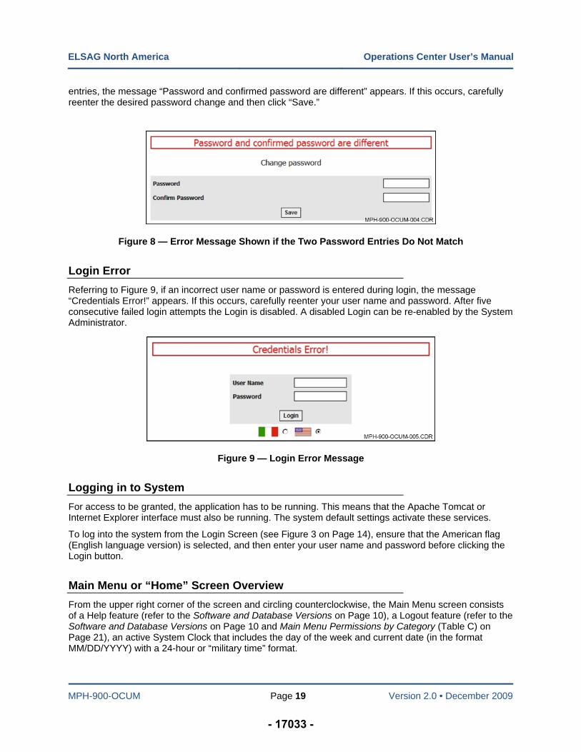
entries, the message “Password and confirmed password are different” appears. If this occurs, carefully reenter the desired password change and then click “Save.”
Figure 8 — Error Message Shown if the Two Password Entries Do Not Match
Login Error
Referring to Figure 9, if an incorrect user name or password is entered during login, the message “Credentials Error!” appears. If this occurs, carefully reenter your user name and password. After five consecutive failed login attempts the Login is disabled. A disabled Login can be re-enabled by the System Administrator.
Figure 9 — Login Error Message
Logging in to System
For access to be granted, the application has to be running. This means that the Apache Tomcat or Internet Explorer interface must also be running. The system default settings activate these services.
To log into the system from the Login Screen (see Figure 3 on Page 14), ensure that the American flag (English language version) is selected, and then enter your user name and password before clicking the Login button.
Main Menu or “Home” Screen Overview
From the upper right corner of the screen and circling counterclockwise, the Main Menu screen consists of a Help feature (refer to the Software and Database Versions on Page 10), a Logout feature (refer to the Software and Database Versions on Page 10 and Main Menu Permissions by Category (Table C) on Page 21), an active System Clock that includes the day of the week and current date (in the format MM/DD/YYYY) with a 24-hour or “military time” format.
- 17033 -
ELSAG North America Operations Center User’s Manual
MPH-900-OCUM Page 20 Version 2.0 • December 2009
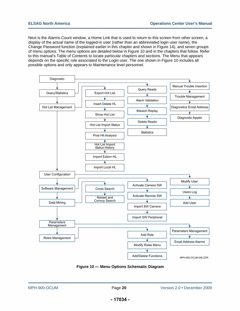
Next is the Alarms Count window, a Home Link that is used to return to this screen from other screen, a display of the actual name of the logged-in user (rather than an abbreviated login user name), the Change Password function (explained earlier in this chapter and shown in Figure 14), and seven groups of menu options. The menu options are detailed below in Figure 10 and in the chapters that follow. Refer to this manual’s Table of Contents to locate particular chapters and sections. The Menu that appears depends on the specific role associated to the Login user. The one shown in Figure 10 includes all possible options and only appears to Maintenance level personnel.
Figure 10 — Menu Options Schematic Diagram
- 17034 -
ELSAG North America Operations Center User’s Manual
MPH-900-OCUM Page 21 Version 2.0 • December 2009
Main Menu Permissions
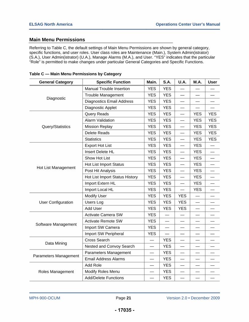
Referring to Table C, the default settings of Main Menu Permissions are shown by general category, specific functions, and user roles. User class roles are Maintenance (Main.), System Admin(istrator) (S.A.), User Admin(istrator) (U.A.), Manage Alarms (M.A.), and User. “YES” indicates that the particular “Role” is permitted to make changes under particular General Categories and Specific Functions.
Table C — Main Menu Permissions by Category
General Category Specific Function Main. S.A. U.A. M.A. User
Diagnostic
Manual Trouble Insertion YES YES — — —
Trouble Management YES YES — — —
Diagnostics Email Address YES YES — — —
Diagnostic Applet YES YES — — —
Query/Statistics
Query Reads YES YES — YES YES
Alarm Validation YES YES — YES YES
Mission Replay YES YES — YES YES
Delete Reads YES YES — YES YES
Statistics YES YES — YES YES
Hot List Management
Export Hot List YES YES — YES —
Insert Delete HL YES YES — YES —
Show Hot List YES YES — YES —
Hot List Import Status YES YES — YES —
Post Hit Analysis YES YES — YES —
Hot List Import Status History YES YES — YES —
Import Extern HL YES YES — YES —
Import Local HL YES YES — YES —
User Configuration
Modify User YES YES YES — —
Users Log YES YES YES — —
Add User YES YES YES — —
Software Management
Activate Camera SW YES — — — —
Activate Remote SW YES — — — —
Import SW Camera YES — — — —
Import SW Peripheral YES — — — —
Data Mining Cross Search — YES — — —
Nested and Convoy Search — YES — — —
Parameters Management Parameters Management — YES — — —
Email Address Alarms — YES — — —
Roles Management
Add Role — YES — — —
Modify Roles Menu — YES — — —
Add/Delete Functions — YES — — —
- 17035 -
ELSAG North America Operations Center User’s Manual
MPH-900-OCUM Page 22 Version 2.0 • December 2009
Logout Feature
Select “Logout” to return to the Login screen. This method is preferred to simply closing the Web browser. Refer to Figure 11.
Figure 11 — Logout Feature and Help Button
System Clock
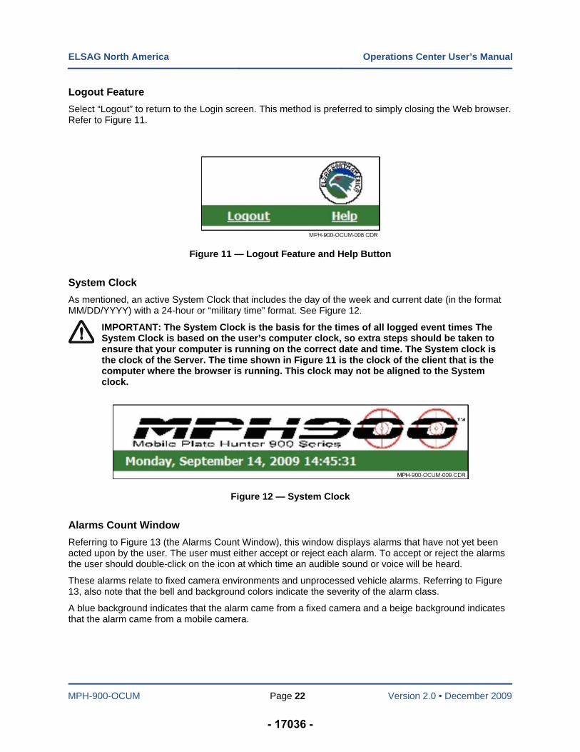
As mentioned, an active System Clock that includes the day of the week and current date (in the format MM/DD/YYYY) with a 24-hour or “military time” format. See Figure 12.
IMPORTANT: The System Clock is the basis for the times of all logged event times The System Clock is based on the user’s computer clock, so extra steps should be taken to ensure that your computer is running on the correct date and time. The System clock is the clock of the Server. The time shown in Figure 11 is the clock of the client that is the computer where the browser is running. This clock may not be aligned to the System clock.
Figure 12 — System Clock
Alarms Count Window
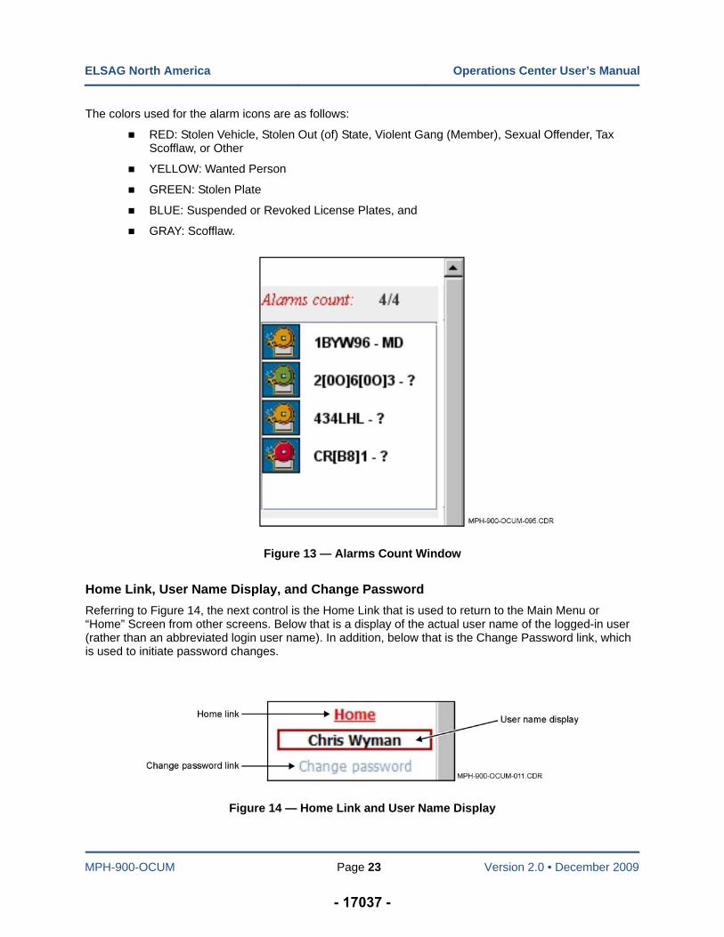
Referring to Figure 13 (the Alarms Count Window), this window displays alarms that have not yet been acted upon by the user. The user must either accept or reject each alarm. To accept or reject the alarms the user should double-click on the icon at which time an audible sound or voice will be heard.
These alarms relate to fixed camera environments and unprocessed vehicle alarms. Referring to Figure 13, also note that the bell and background colors indicate the severity of the alarm class.
A blue background indicates that the alarm came from a fixed camera and a beige background indicates that the alarm came from a mobile camera.
- 17036 -
ELSAG North America Operations Center User’s Manual
MPH-900-OCUM Page 23 Version 2.0 • December 2009
The colors used for the alarm icons are as follows:
RED: Stolen Vehicle, Stolen Out (of) State, Violent Gang (Member), Sexual Offender, Tax Scofflaw, or Other
YELLOW: Wanted Person
GREEN: Stolen Plate
BLUE: Suspended or Revoked License Plates, and
GRAY: Scofflaw.
Figure 13 — Alarms Count Window
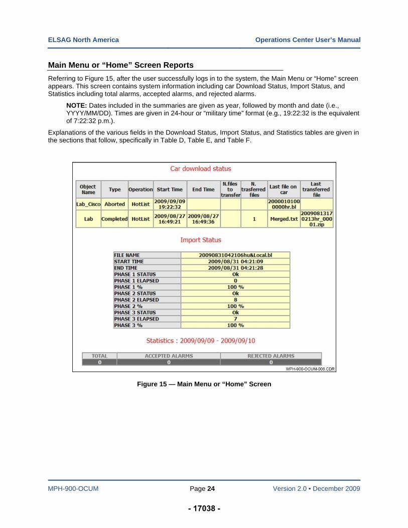
Home Link, User Name Display, and Change Password
Referring to Figure 14, the next control is the Home Link that is used to return to the Main Menu or “Home” Screen from other screens. Below that is a display of the actual user name of the logged-in user (rather than an abbreviated login user name). In addition, below that is the Change Password link, which is used to initiate password changes.
Figure 14 — Home Link and User Name Display
- 17037 -
ELSAG North America Operations Center User’s Manual
MPH-900-OCUM Page 24 Version 2.0 • December 2009
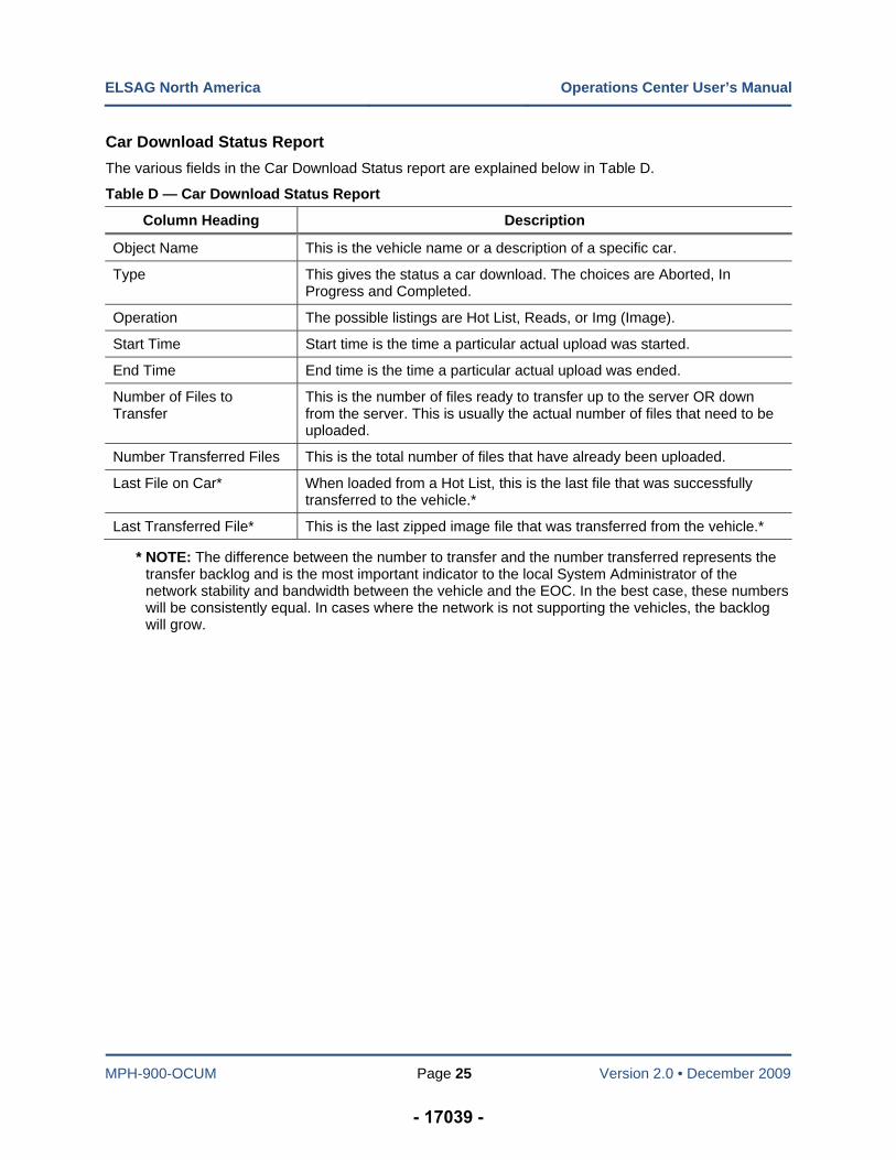
Main Menu or “Home” Screen Reports
Referring to Figure 15, after the user successfully logs in to the system, the Main Menu or “Home” screen appears. This screen contains system information including car Download Status, Import Status, and Statistics including total alarms, accepted alarms, and rejected alarms.
NOTE: Dates included in the summaries are given as year, followed by month and date (i.e., YYYY/MM/DD). Times are given in 24-hour or “military time” format (e.g., 19:22:32 is the equivalent of 7:22:32 p.m.).
Explanations of the various fields in the Download Status, Import Status, and Statistics tables are given in the sections that follow, specifically in Table D, Table E, and Table F.
Figure 15 — Main Menu or “Home” Screen
- 17038 -
ELSAG North America Operations Center User’s Manual
MPH-900-OCUM Page 25 Version 2.0 • December 2009
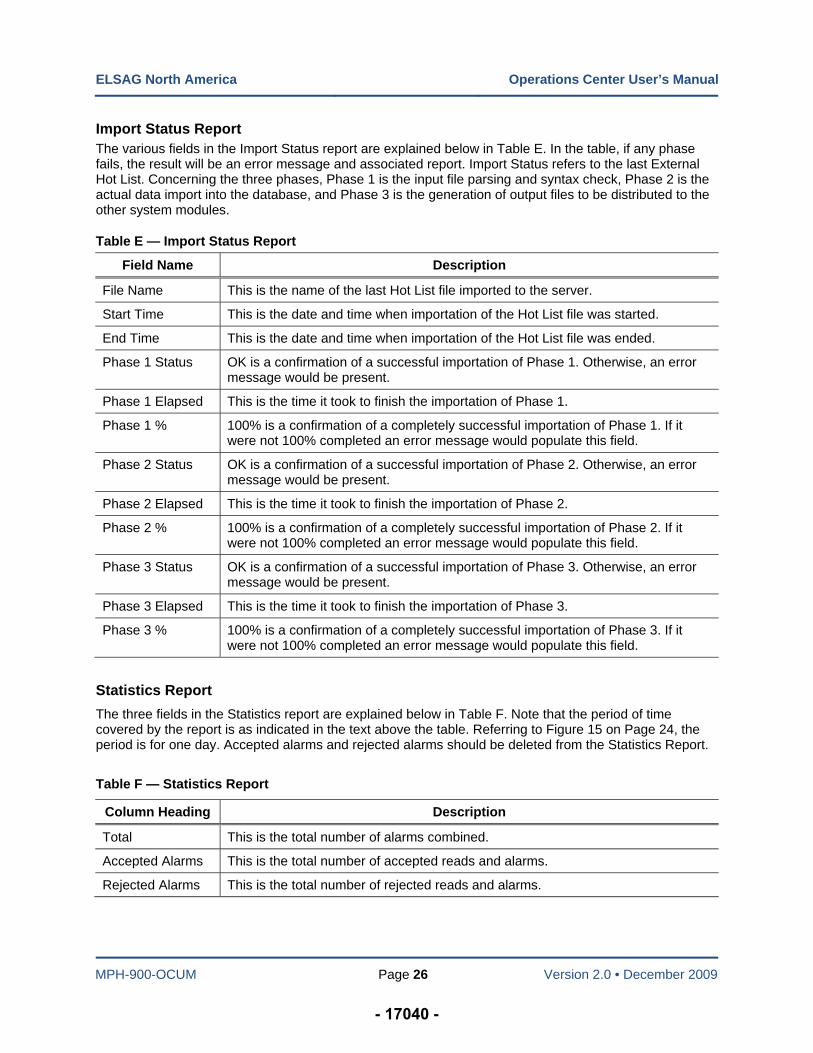
Car Download Status Report
The various fields in the Car Download Status report are explained below in Table D.
Table D — Car Download Status Report
Column Heading Description
Object Name This is the vehicle name or a description of a specific car.
Type This gives the status a car download. The choices are Aborted, In Progress and Completed.
Operation The possible listings are Hot List, Reads, or Img (Image).
Start Time Start time is the time a particular actual upload was started.
End Time End time is the time a particular actual upload was ended.
Number of Files to Transfer
This is the number of files ready to transfer up to the server OR down from the server. This is usually the actual number of files that need to be uploaded.
Number Transferred Files This is the total number of files that have already been uploaded.
Last File on Car* When loaded from a Hot List, this is the last file that was successfully transferred to the vehicle.*
Last Transferred File* This is the last zipped image file that was transferred from the vehicle.*
* NOTE: The difference between the number to transfer and the number transferred represents the transfer backlog and is the most important indicator to the local System Administrator of the network stability and bandwidth between the vehicle and the EOC. In the best case, these numbers will be consistently equal. In cases where the network is not supporting the vehicles, the backlog will grow.
- 17039 -
ELSAG North America Operations Center User’s Manual
MPH-900-OCUM Page 26 Version 2.0 • December 2009
Import Status Report The various fields in the Import Status report are explained below in Table E. In the table, if any phase fails, the result will be an error message and associated report. Import Status refers to the last External Hot List. Concerning the three phases, Phase 1 is the input file parsing and syntax check, Phase 2 is the actual data import into the database, and Phase 3 is the generation of output files to be distributed to the other system modules.
Table E — Import Status Report
Field Name Description
File Name This is the name of the last Hot List file imported to the server.
Start Time This is the date and time when importation of the Hot List file was started.
End Time This is the date and time when importation of the Hot List file was ended.
Phase 1 Status OK is a confirmation of a successful importation of Phase 1. Otherwise, an error message would be present.
Phase 1 Elapsed This is the time it took to finish the importation of Phase 1.
Phase 1 % 100% is a confirmation of a completely successful importation of Phase 1. If it were not 100% completed an error message would populate this field.
Phase 2 Status OK is a confirmation of a successful importation of Phase 2. Otherwise, an error message would be present.
Phase 2 Elapsed This is the time it took to finish the importation of Phase 2.
Phase 2 % 100% is a confirmation of a completely successful importation of Phase 2. If it were not 100% completed an error message would populate this field.
Phase 3 Status OK is a confirmation of a successful importation of Phase 3. Otherwise, an error message would be present.
Phase 3 Elapsed This is the time it took to finish the importation of Phase 3.
Phase 3 % 100% is a confirmation of a completely successful importation of Phase 3. If it were not 100% completed an error message would populate this field.
Statistics Report
The three fields in the Statistics report are explained below in Table F. Note that the period of time covered by the report is as indicated in the text above the table. Referring to Figure 15 on Page 24, the period is for one day. Accepted alarms and rejected alarms should be deleted from the Statistics Report.
Table F — Statistics Report
Column Heading Description
Total This is the total number of alarms combined.
Accepted Alarms This is the total number of accepted reads and alarms.
Rejected Alarms This is the total number of rejected reads and alarms.
- 17040 -
ELSAG North America Operations Center User’s Manual
MPH-900-OCUM Page 27 Version 2.0 • December 2009
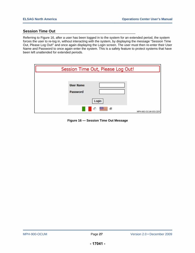
Session Time Out
Referring to Figure 16, after a user has been logged in to the system for an extended period, the system forces the user to re-log in, without interacting with the system, by displaying the message “Session Time Out, Please Log Out!” and once again displaying the Login screen. The user must then re-enter their User Name and Password to once again enter the system. This is a safety feature to protect systems that have been left unattended for extended periods.
Figure 16 — Session Time Out Message
- 17041 -
MPH-900-OCUM Page 28 Version 2.0 • December 2009
Chapter 4 — Diagnostic Features
Introduction
The available Diagnostic Features explained in this chapter are as follows:
Manual Trouble Insertion
Trouble Management
Diagnostics Email Address, and
Diagnostic Applet.
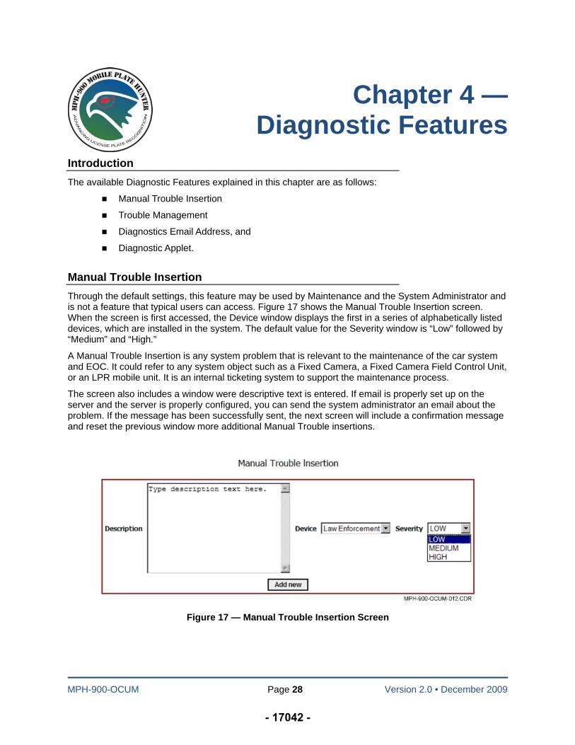
Manual Trouble Insertion
Through the default settings, this feature may be used by Maintenance and the System Administrator and is not a feature that typical users can access. Figure 17 shows the Manual Trouble Insertion screen. When the screen is first accessed, the Device window displays the first in a series of alphabetically listed devices, which are installed in the system. The default value for the Severity window is “Low” followed by “Medium” and “High.”
A Manual Trouble Insertion is any system problem that is relevant to the maintenance of the car system and EOC. It could refer to any system object such as a Fixed Camera, a Fixed Camera Field Control Unit, or an LPR mobile unit. It is an internal ticketing system to support the maintenance process.
The screen also includes a window were descriptive text is entered. If email is properly set up on the server and the server is properly configured, you can send the system administrator an email about the problem. If the message has been successfully sent, the next screen will include a confirmation message and reset the previous window more additional Manual Trouble insertions.
Figure 17 — Manual Trouble Insertion Screen
- 17042 -
ELSAG North America Operations Center User’s Manual
MPH-900-OCUM Page 29 Version 2.0 • December 2009
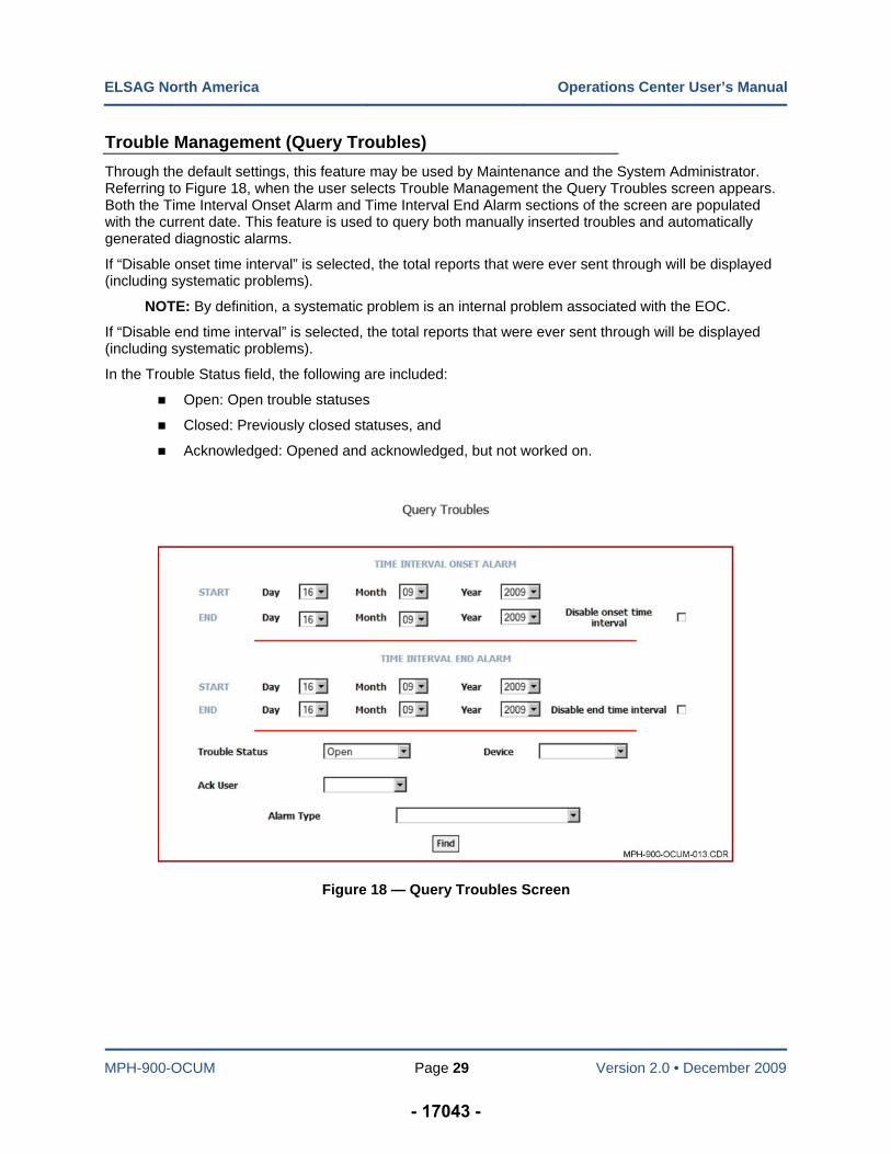
Trouble Management (Query Troubles)
Through the default settings, this feature may be used by Maintenance and the System Administrator. Referring to Figure 18, when the user selects Trouble Management the Query Troubles screen appears. Both the Time Interval Onset Alarm and Time Interval End Alarm sections of the screen are populated with the current date. This feature is used to query both manually inserted troubles and automatically generated diagnostic alarms.
If “Disable onset time interval” is selected, the total reports that were ever sent through will be displayed (including systematic problems).
NOTE: By definition, a systematic problem is an internal problem associated with the EOC.
If “Disable end time interval” is selected, the total reports that were ever sent through will be displayed (including systematic problems).
In the Trouble Status field, the following are included:
Open: Open trouble statuses
Closed: Previously closed statuses, and
Acknowledged: Opened and acknowledged, but not worked on.
Figure 18 — Query Troubles Screen
- 17043 -
ELSAG North America Operations Center User’s Manual
MPH-900-OCUM Page 30 Version 2.0 • December 2009
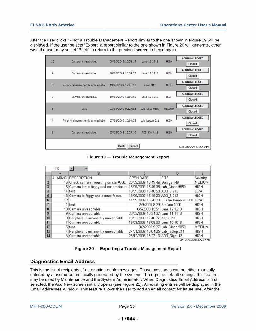
After the user clicks “Find” a Trouble Management Report similar to the one shown in Figure 19 will be displayed. If the user selects “Export” a report similar to the one shown in Figure 20 will generate, other wise the user may select “Back” to return to the previous screen to begin again.
Figure 19 — Trouble Management Report
Figure 20 — Exporting a Trouble Management Report
Diagnostics Email Address
This is the list of recipients of automatic trouble messages. Those messages can be either manually entered by a user or automatically generated by the system. Through the default settings, this feature may be used by Maintenance and the System Administrator. When Diagnostics Email Address is first selected, the Add New screen initially opens (see Figure 21). All existing entries will be displayed in the Email Addresses Window. This feature allows the user to add an email contact for future use. After the
- 17044 -
ELSAG North America Operations Center User’s Manual
MPH-900-OCUM Page 31 Version 2.0 • December 2009
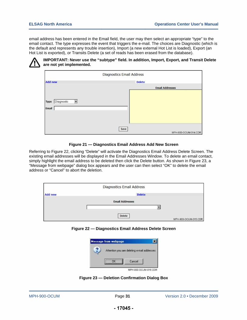
email address has been entered in the Email field, the user may then select an appropriate “type” to the email contact. The type expresses the event that triggers the e-mail. The choices are Diagnostic (which is the default and represents any trouble insertion), Import (a new external Hot List is loaded), Export (an Hot List is exported), or Transits Delete (a set of reads has been erased from the database).
IMPORTANT: Never use the “subtype” field. In addition, Import, Export, and Transit Delete are not yet implemented.
Figure 21 — Diagnostics Email Address Add New Screen
Referring to Figure 22, clicking “Delete” will activate the Diagnostics Email Address Delete Screen. The existing email addresses will be displayed in the Email Addresses Window. To delete an email contact, simply highlight the email address to be deleted then click the Delete button. As shown in Figure 23, a “Message from webpage” dialog box appears and the user can then select “OK” to delete the email address or “Cancel” to abort the deletion.
Figure 22 — Diagnostics Email Address Delete Screen
Figure 23 — Deletion Confirmation Dialog Box
- 17045 -
ELSAG North America Operations Center User’s Manual
MPH-900-OCUM Page 32 Version 2.0 • December 2009
Diagnostic Applet
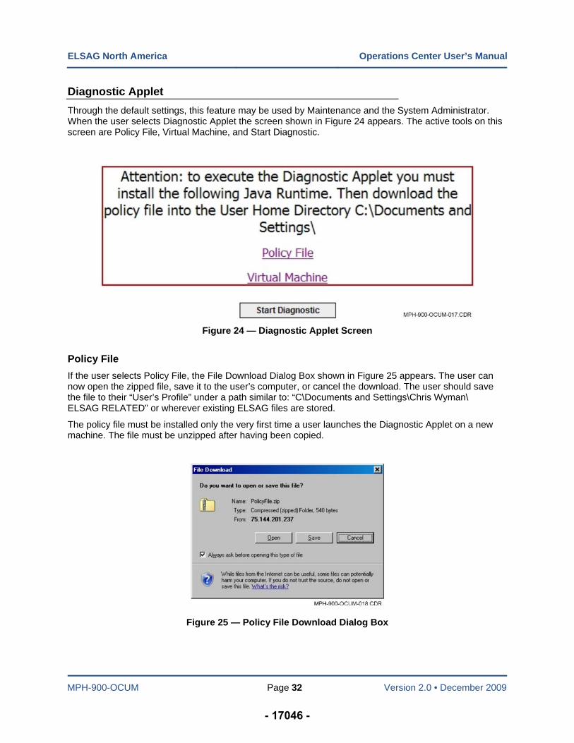
Through the default settings, this feature may be used by Maintenance and the System Administrator. When the user selects Diagnostic Applet the screen shown in Figure 24 appears. The active tools on this screen are Policy File, Virtual Machine, and Start Diagnostic.
Figure 24 — Diagnostic Applet Screen
Policy File
If the user selects Policy File, the File Download Dialog Box shown in Figure 25 appears. The user can now open the zipped file, save it to the user’s computer, or cancel the download. The user should save the file to their “User’s Profile” under a path similar to: “C\Documents and Settings\Chris Wyman\ ELSAG RELATED” or wherever existing ELSAG files are stored.
The policy file must be installed only the very first time a user launches the Diagnostic Applet on a new machine. The file must be unzipped after having been copied.
Figure 25 — Policy File Download Dialog Box
- 17046 -
ELSAG North America Operations Center User’s Manual
MPH-900-OCUM Page 33 Version 2.0 • December 2009
Virtual Machine
If the user selects Virtual Machine, a screen similar to the one shown in Figure 26 appears. To run the application it must be installed. Otherwise, install a Java virtual machine from the Web site link. The Virtual machine must be installed only the very first time a user launches the Diagnostic Applet on a new machine.
To install the Virtual Machine, first select Diagnostic, then select Diagnostic Applet. Referring to Figure 24 on Page 32, click on “Virtual Machine” and an installation screen appears (see Figure 26 below). Click “Save” to save the file to a specific folder and then run the installation from that location by following the onscreen instructions. Otherwise, click run and follow the onscreen instructions.
Figure 26 — Virtual Machine Identification Screen
Start Diagnostic
When the user selects Start Diagnostic an additional browser window opens and displays the Java Logo (see Figure 27). Immediately after the Java window opens the Operational Center Diagnostic Dialog Box appears (see Figure 28).
Figure 27 — Java Logo
- 17047 -
ELSAG North America Operations Center User’s Manual
MPH-900-OCUM Page 34 Version 2.0 • December 2009
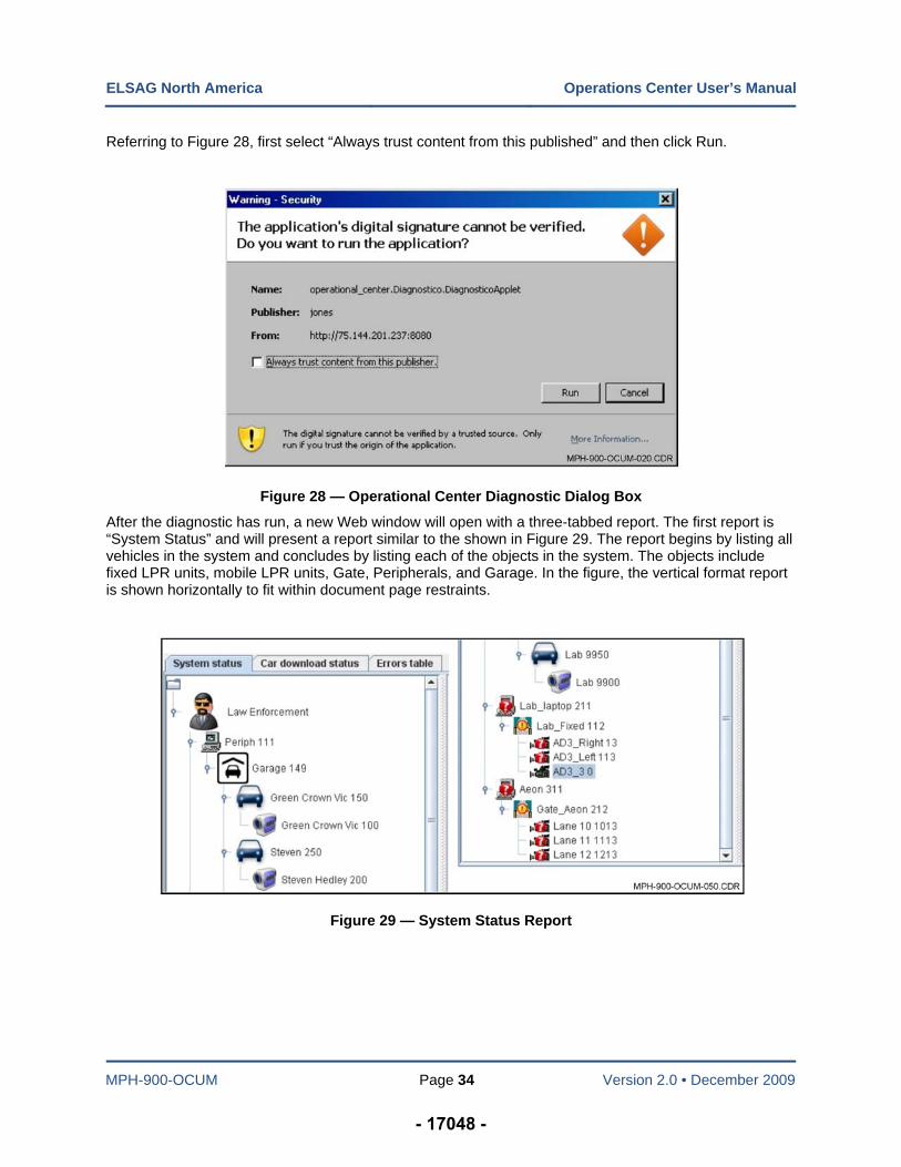
Referring to Figure 28, first select “Always trust content from this published” and then click Run.
Figure 28 — Operational Center Diagnostic Dialog Box
After the diagnostic has run, a new Web window will open with a three-tabbed report. The first report is “System Status” and will present a report similar to the shown in Figure 29. The report begins by listing all vehicles in the system and concludes by listing each of the objects in the system. The objects include fixed LPR units, mobile LPR units, Gate, Peripherals, and Garage. In the figure, the vertical format report is shown horizontally to fit within document page restraints.
Figure 29 — System Status Report
- 17048 -
ELSAG North America Operations Center User’s Manual
MPH-900-OCUM Page 35 Version 2.0 • December 2009
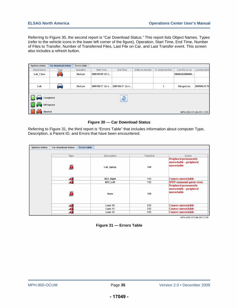
Referring to Figure 30, the second report is “Car Download Status.” This report lists Object Names. Types (refer to the vehicle icons in the lower left corner of the figure), Operation, Start Time, End Time, Number of Files to Transfer, Number of Transferred Files, Last File on Car, and Last Transfer event. This screen also includes a refresh button.
Figure 30 — Car Download Status
Referring to Figure 31, the third report is “Errors Table” that includes information about computer Type, Description, a Parent ID, and Errors that have been encountered.
Figure 31 — Errors Table
- 17049 -
MPH-900-OCUM Page 36 Version 2.0 • December 2009
Chapter 5 — Query/Statistics
Introduction
The available Query/Statistics functions explained in this chapter are as follows: Query Reads, Alarm Validation, Mission Replay, Delete Reads, and Statistics.
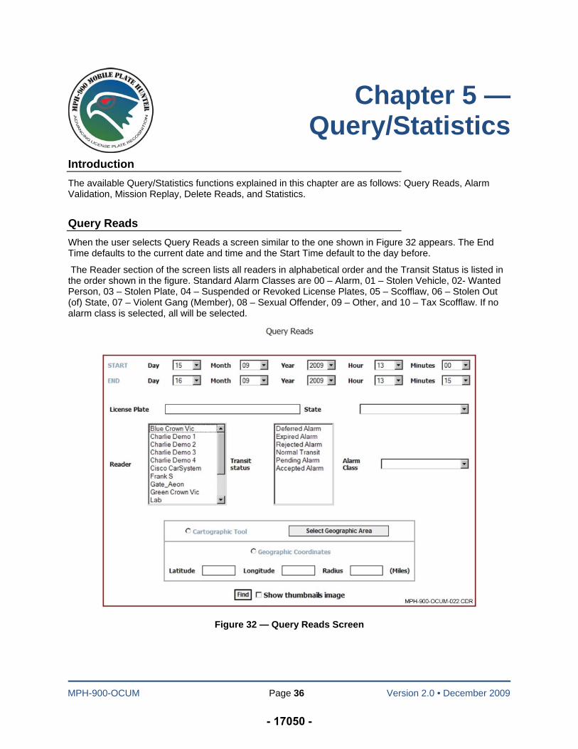
Query Reads
When the user selects Query Reads a screen similar to the one shown in Figure 32 appears. The End Time defaults to the current date and time and the Start Time default to the day before.
The Reader section of the screen lists all readers in alphabetical order and the Transit Status is listed in the order shown in the figure. Standard Alarm Classes are 00 – Alarm, 01 – Stolen Vehicle, 02- Wanted Person, 03 – Stolen Plate, 04 – Suspended or Revoked License Plates, 05 – Scofflaw, 06 – Stolen Out (of) State, 07 – Violent Gang (Member), 08 – Sexual Offender, 09 – Other, and 10 – Tax Scofflaw. If no alarm class is selected, all will be selected.
Figure 32 — Query Reads Screen
- 17050 -
ELSAG North America Operations Center User’s Manual
MPH-900-OCUM Page 37 Version 2.0 • December 2009
The Reader Window lists each of the vehicles and fixed cameras that are part of the system. The Transit Status Window includes the following categories:
Deferred Alarm (alarm that timed out at the user end and no action was taken against it)
Expired Alarm (alarm that was expired by the system, expiration time for a deferred alarm)
Rejected Alarm (alarm that was rejected the user)
Normal Transit (regular read from the vehicle or fixed camera)
Pending Alarm (pending acknowledgement by the end user [usually fixed camera]), and
Accepted Alarm (alarm that was accepted by the user).
To generate a report in Query Reads, select the desired start and end dates and times and any other specific criteria that the user wishes to include in the report (Select Geographic Area [Map Based Searches] will be covered later in this section), then select “Show Thumbnails Image” and click “Find.”
NOTE: Items not selected will in turn search for all items in a particular window.
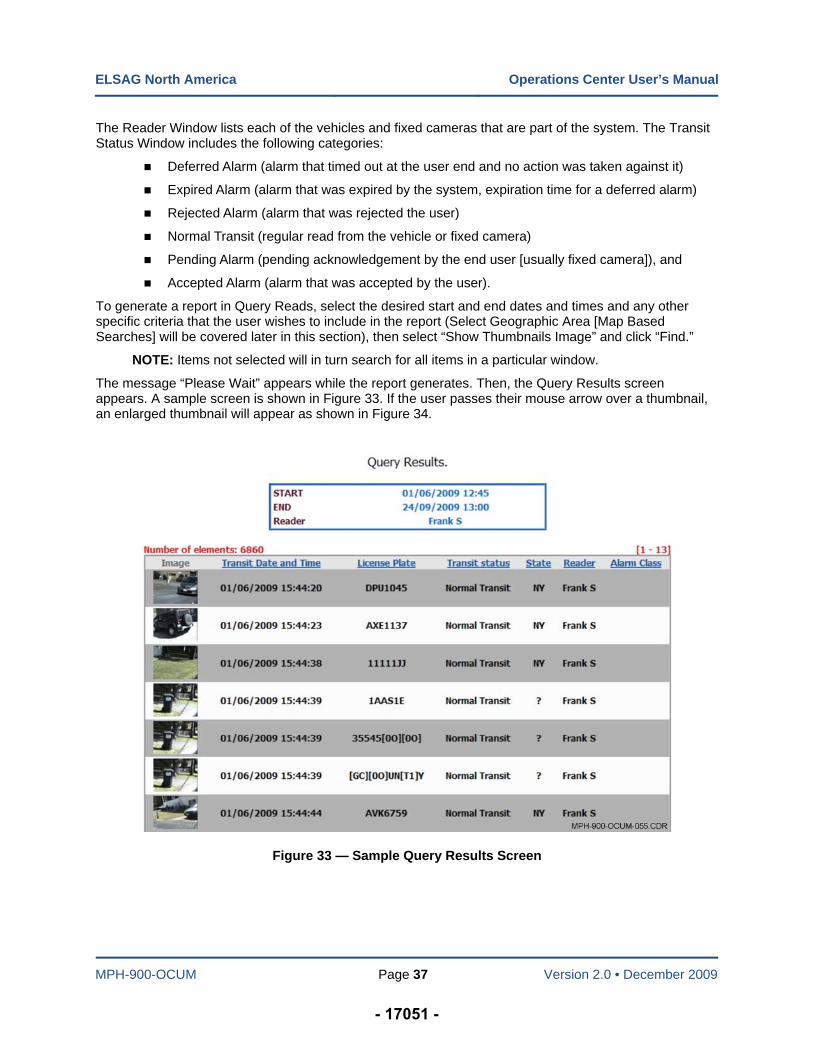
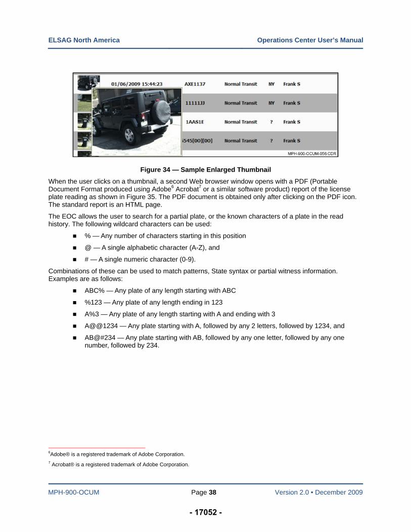
The message “Please Wait” appears while the report generates. Then, the Query Results screen appears. A sample screen is shown in Figure 33. If the user passes their mouse arrow over a thumbnail, an enlarged thumbnail will appear as shown in Figure 34.
Figure 33 — Sample Query Results Screen
- 17051 -
ELSAG North America Operations Center User’s Manual
MPH-900-OCUM Page 38 Version 2.0 • December 2009
Figure 34 — Sample Enlarged Thumbnail
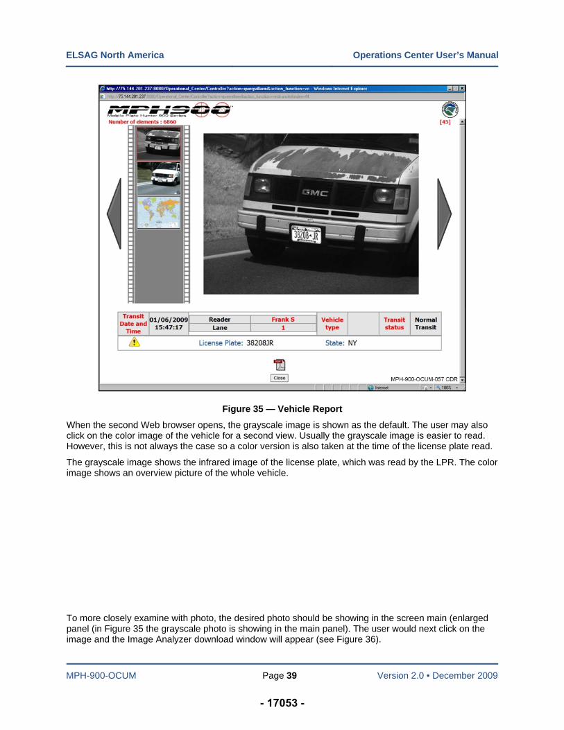
When the user clicks on a thumbnail, a second Web browser window opens with a PDF (Portable Document Format produced using Adobe6 Acrobat7 or a similar software product) report of the license plate reading as shown in Figure 35. The PDF document is obtained only after clicking on the PDF icon. The standard report is an HTML page.
The EOC allows the user to search for a partial plate, or the known characters of a plate in the read history. The following wildcard characters can be used:
% — Any number of characters starting in this position
@ — A single alphabetic character (A-Z), and
# — A single numeric character (0-9).
Combinations of these can be used to match patterns, State syntax or partial witness information. Examples are as follows:
ABC% — Any plate of any length starting with ABC
%123 — Any plate of any length ending in 123
A%3 — Any plate of any length starting with A and ending with 3
A@@1234 — Any plate starting with A, followed by any 2 letters, followed by 1234, and
AB@#234 — Any plate starting with AB, followed by any one letter, followed by any one number, followed by 234.
6Adobe® is a registered trademark of Adobe Corporation.
7 Acrobat® is a registered trademark of Adobe Corporation.
- 17052 -
ELSAG North America Operations Center User’s Manual
MPH-900-OCUM Page 39 Version 2.0 • December 2009
Figure 35 — Vehicle Report
When the second Web browser opens, the grayscale image is shown as the default. The user may also click on the color image of the vehicle for a second view. Usually the grayscale image is easier to read. However, this is not always the case so a color version is also taken at the time of the license plate read.
The grayscale image shows the infrared image of the license plate, which was read by the LPR. The color image shows an overview picture of the whole vehicle.
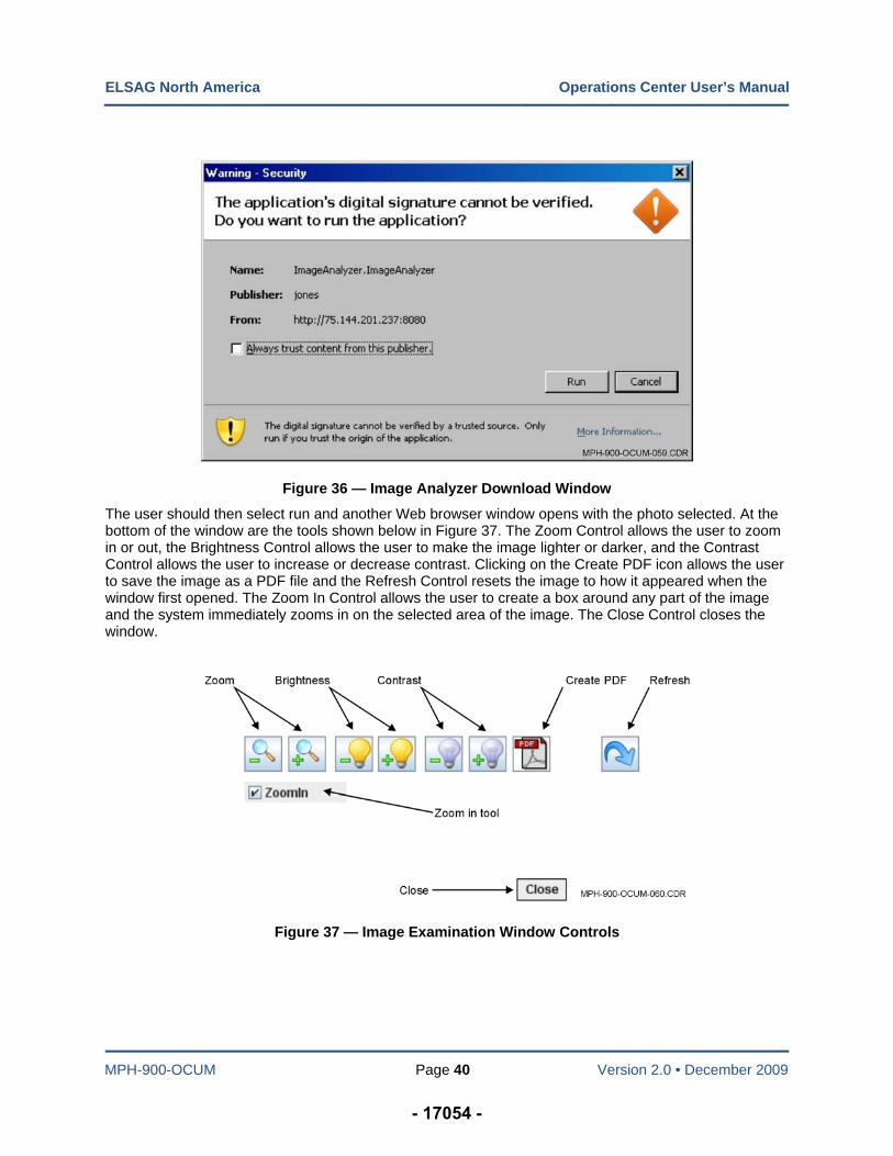
To more closely examine with photo, the desired photo should be showing in the screen main (enlarged panel (in Figure 35 the grayscale photo is showing in the main panel). The user would next click on the image and the Image Analyzer download window will appear (see Figure 36).
- 17053 -
ELSAG North America Operations Center User’s Manual
MPH-900-OCUM Page 40 Version 2.0 • December 2009
Figure 36 — Image Analyzer Download Window
The user should then select run and another Web browser window opens with the photo selected. At the bottom of the window are the tools shown below in Figure 37. The Zoom Control allows the user to zoom in or out, the Brightness Control allows the user to make the image lighter or darker, and the Contrast Control allows the user to increase or decrease contrast. Clicking on the Create PDF icon allows the user to save the image as a PDF file and the Refresh Control resets the image to how it appeared when the window first opened. The Zoom In Control allows the user to create a box around any part of the image and the system immediately zooms in on the selected area of the image. The Close Control closes the window.
Figure 37 — Image Examination Window Controls
- 17054 -
ELSAG North America Operations Center User’s Manual
MPH-900-OCUM Page 41 Version 2.0 • December 2009
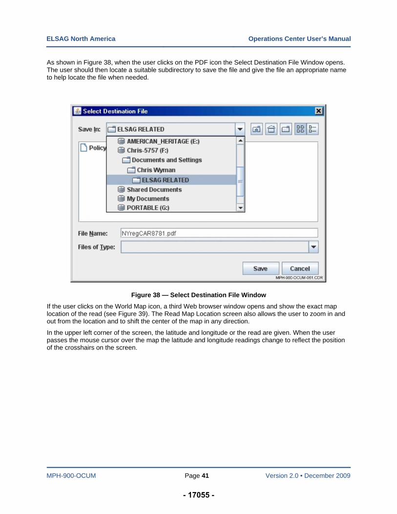
As shown in Figure 38, when the user clicks on the PDF icon the Select Destination File Window opens. The user should then locate a suitable subdirectory to save the file and give the file an appropriate name to help locate the file when needed.
Figure 38 — Select Destination File Window
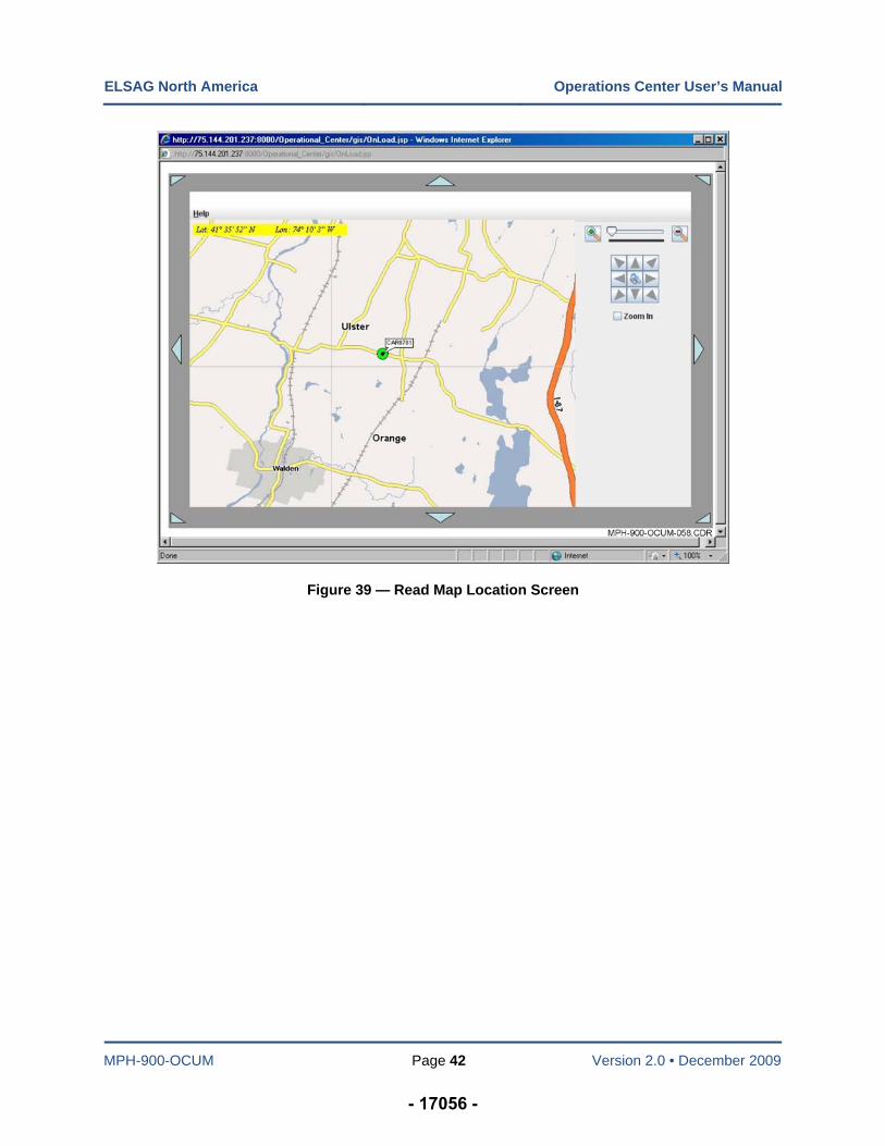
If the user clicks on the World Map icon, a third Web browser window opens and show the exact map location of the read (see Figure 39). The Read Map Location screen also allows the user to zoom in and out from the location and to shift the center of the map in any direction.
In the upper left corner of the screen, the latitude and longitude or the read are given. When the user passes the mouse cursor over the map the latitude and longitude readings change to reflect the position of the crosshairs on the screen.
- 17055 -
ELSAG North America Operations Center User’s Manual
MPH-900-OCUM Page 42 Version 2.0 • December 2009
Figure 39 — Read Map Location Screen
- 17056 -
ELSAG North America Operations Center User’s Manual
MPH-900-OCUM Page 43 Version 2.0 • December 2009
Map Based Searches
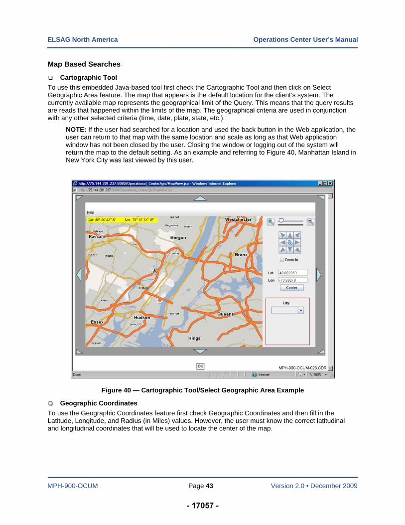
Cartographic Tool
To use this embedded Java-based tool first check the Cartographic Tool and then click on Select Geographic Area feature. The map that appears is the default location for the client’s system. The currently available map represents the geographical limit of the Query. This means that the query results are reads that happened within the limits of the map. The geographical criteria are used in conjunction with any other selected criteria (time, date, plate, state, etc.).
NOTE: If the user had searched for a location and used the back button in the Web application, the user can return to that map with the same location and scale as long as that Web application window has not been closed by the user. Closing the window or logging out of the system will return the map to the default setting. As an example and referring to Figure 40, Manhattan Island in New York City was last viewed by this user.
Figure 40 — Cartographic Tool/Select Geographic Area Example
Geographic Coordinates
To use the Geographic Coordinates feature first check Geographic Coordinates and then fill in the Latitude, Longitude, and Radius (in Miles) values. However, the user must know the correct latitudinal and longitudinal coordinates that will be used to locate the center of the map.
- 17057 -
ELSAG North America Operations Center User’s Manual
MPH-900-OCUM Page 44 Version 2.0 • December 2009
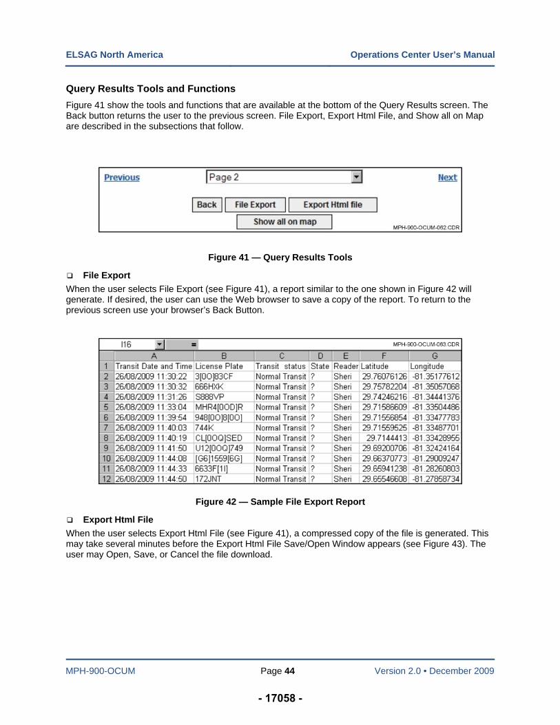
Query Results Tools and Functions
Figure 41 show the tools and functions that are available at the bottom of the Query Results screen. The Back button returns the user to the previous screen. File Export, Export Html File, and Show all on Map are described in the subsections that follow.
Figure 41 — Query Results Tools
File Export
When the user selects File Export (see Figure 41), a report similar to the one shown in Figure 42 will generate. If desired, the user can use the Web browser to save a copy of the report. To return to the previous screen use your browser’s Back Button.
Figure 42 — Sample File Export Report
Export Html File
When the user selects Export Html File (see Figure 41), a compressed copy of the file is generated. This may take several minutes before the Export Html File Save/Open Window appears (see Figure 43). The user may Open, Save, or Cancel the file download.
- 17058 -
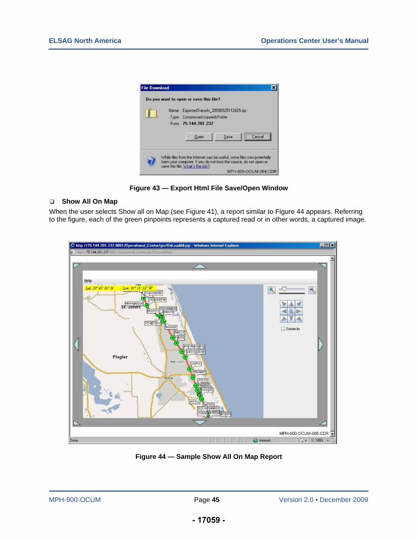
ELSAG North America Operations Center User’s Manual
MPH-900-OCUM Page 45 Version 2.0 • December 2009
Figure 43 — Export Html File Save/Open Window
Show All On Map
When the user selects Show all on Map (see Figure 41), a report similar to Figure 44 appears. Referring to the figure, each of the green pinpoints represents a captured read or in other words, a captured image.
Figure 44 — Sample Show All On Map Report
- 17059 -
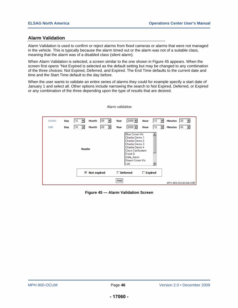
ELSAG North America Operations Center User’s Manual
MPH-900-OCUM Page 46 Version 2.0 • December 2009
Alarm Validation
Alarm Validation is used to confirm or reject alarms from fixed cameras or alarms that were not managed in the vehicle. This is typically because the alarm timed out or the alarm was not of a suitable class, meaning that the alarm was of a disabled class (silent alarm).
When Alarm Validation is selected, a screen similar to the one shown in Figure 45 appears. When the screen first opens “Not Expired is selected as the default setting but may be changed to any combination of the three choices: Not Expired, Deferred, and Expired. The End Time defaults to the current date and time and the Start Time default to the day before.
When the user wants to validate an entire series of alarms they could for example specify a start date of January 1 and select all. Other options include narrowing the search to Not Expired, Deferred, or Expired or any combination of the three depending upon the type of results that are desired.
Figure 45 — Alarm Validation Screen
- 17060 -
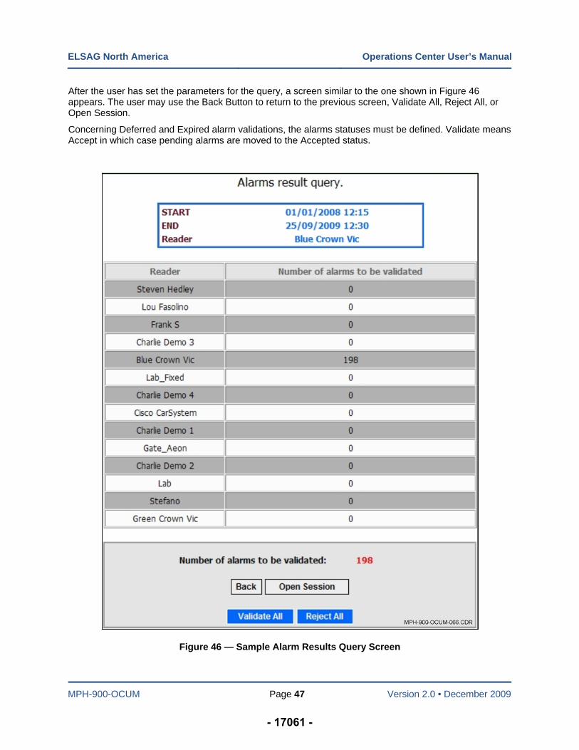
ELSAG North America Operations Center User’s Manual
MPH-900-OCUM Page 47 Version 2.0 • December 2009
After the user has set the parameters for the query, a screen similar to the one shown in Figure 46 appears. The user may use the Back Button to return to the previous screen, Validate All, Reject All, or Open Session.
Concerning Deferred and Expired alarm validations, the alarms statuses must be defined. Validate means Accept in which case pending alarms are moved to the Accepted status.
Figure 46 — Sample Alarm Results Query Screen
- 17061 -
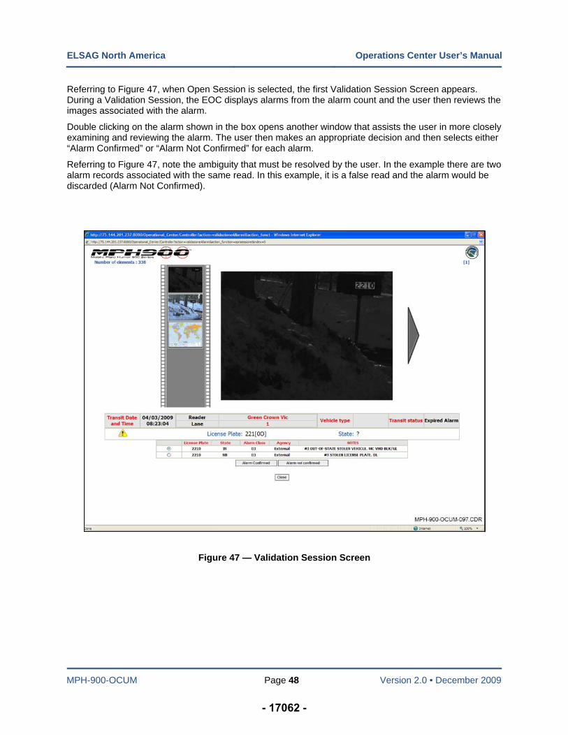
ELSAG North America Operations Center User’s Manual
MPH-900-OCUM Page 48 Version 2.0 • December 2009
Referring to Figure 47, when Open Session is selected, the first Validation Session Screen appears. During a Validation Session, the EOC displays alarms from the alarm count and the user then reviews the images associated with the alarm.
Double clicking on the alarm shown in the box opens another window that assists the user in more closely examining and reviewing the alarm. The user then makes an appropriate decision and then selects either “Alarm Confirmed” or “Alarm Not Confirmed” for each alarm.
Referring to Figure 47, note the ambiguity that must be resolved by the user. In the example there are two alarm records associated with the same read. In this example, it is a false read and the alarm would be discarded (Alarm Not Confirmed).
Figure 47 — Validation Session Screen
- 17062 -
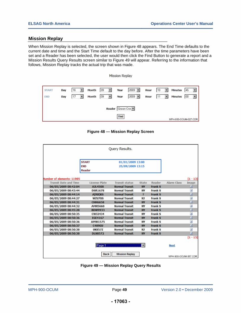
ELSAG North America Operations Center User’s Manual
MPH-900-OCUM Page 49 Version 2.0 • December 2009
Mission Replay
When Mission Replay is selected, the screen shown in Figure 48 appears. The End Time defaults to the current date and time and the Start Time default to the day before. After the time parameters have been set and a Reader has been selected, the user would then click the Find Button to generate a report and a Mission Results Query Results screen similar to Figure 49 will appear. Referring to the information that follows, Mission Replay tracks the actual trip that was made.
Figure 48 — Mission Replay Screen
Figure 49 — Mission Replay Query Results
- 17063 -
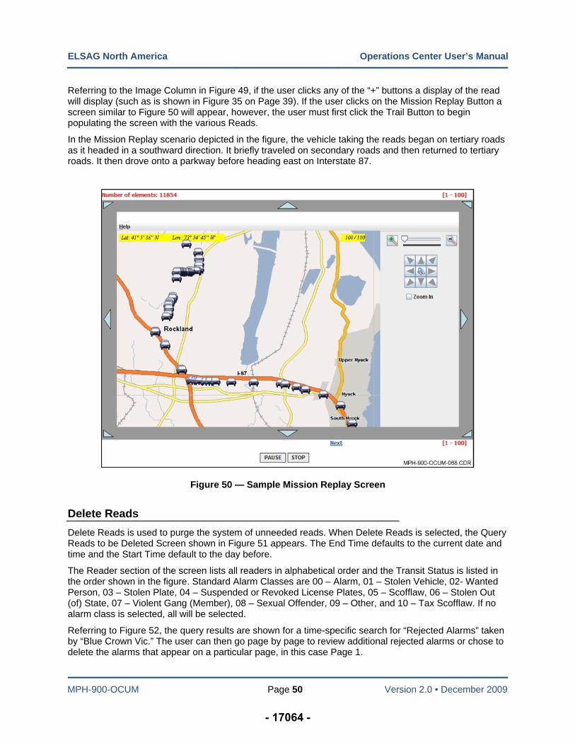
ELSAG North America Operations Center User’s Manual
MPH-900-OCUM Page 50 Version 2.0 • December 2009
Referring to the Image Column in Figure 49, if the user clicks any of the “+” buttons a display of the read will display (such as is shown in Figure 35 on Page 39). If the user clicks on the Mission Replay Button a screen similar to Figure 50 will appear, however, the user must first click the Trail Button to begin populating the screen with the various Reads.
In the Mission Replay scenario depicted in the figure, the vehicle taking the reads began on tertiary roads as it headed in a southward direction. It briefly traveled on secondary roads and then returned to tertiary roads. It then drove onto a parkway before heading east on Interstate 87.
Figure 50 — Sample Mission Replay Screen
Delete Reads
Delete Reads is used to purge the system of unneeded reads. When Delete Reads is selected, the Query Reads to be Deleted Screen shown in Figure 51 appears. The End Time defaults to the current date and time and the Start Time default to the day before.
The Reader section of the screen lists all readers in alphabetical order and the Transit Status is listed in the order shown in the figure. Standard Alarm Classes are 00 – Alarm, 01 – Stolen Vehicle, 02- Wanted Person, 03 – Stolen Plate, 04 – Suspended or Revoked License Plates, 05 – Scofflaw, 06 – Stolen Out (of) State, 07 – Violent Gang (Member), 08 – Sexual Offender, 09 – Other, and 10 – Tax Scofflaw. If no alarm class is selected, all will be selected.
Referring to Figure 52, the query results are shown for a time-specific search for “Rejected Alarms” taken by “Blue Crown Vic.” The user can then go page by page to review additional rejected alarms or chose to delete the alarms that appear on a particular page, in this case Page 1.
- 17064 -
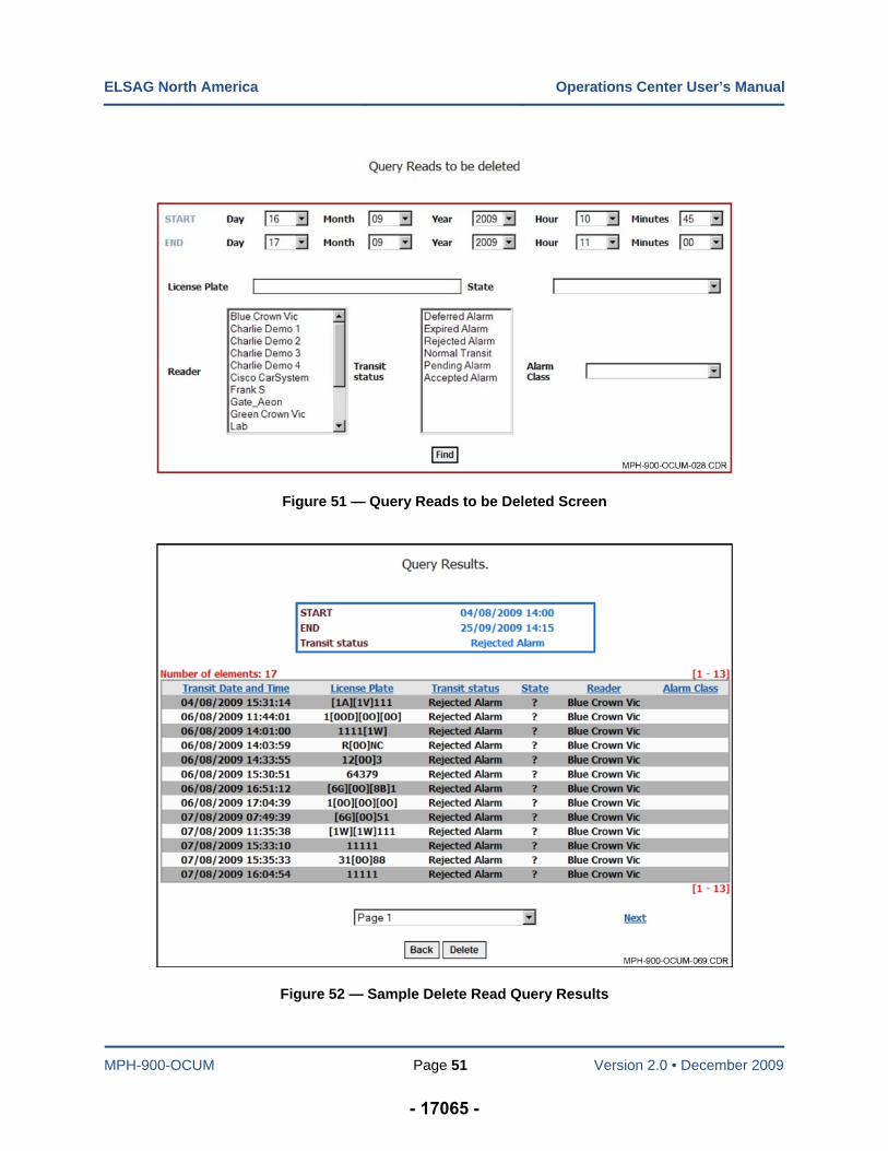
ELSAG North America Operations Center User’s Manual
MPH-900-OCUM Page 51 Version 2.0 • December 2009
Figure 51 — Query Reads to be Deleted Screen
Figure 52 — Sample Delete Read Query Results
- 17065 -
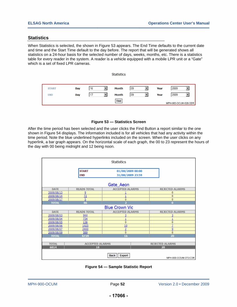
ELSAG North America Operations Center User’s Manual
MPH-900-OCUM Page 52 Version 2.0 • December 2009
Statistics
When Statistics is selected, the shown in Figure 53 appears. The End Time defaults to the current date and time and the Start Time default to the day before. The report that will be generated shows all statistics on a 24-hour basis for the selected number of days, weeks, months, etc. There is a statistics table for every reader in the system. A reader is a vehicle equipped with a mobile LPR unit or a “Gate” which is a set of fixed LPR cameras.
Figure 53 — Statistics Screen
After the time period has been selected and the user clicks the Find Button a report similar to the one shown in Figure 54 displays. The information included is for all vehicles that had any activity within the time period. Note the blue underlined hyperlinks included on the screen. When the user clicks on any hyperlink, a bar graph appears. On the horizontal scale of each graph, the 00 to 23 represent the hours of the day with 00 being midnight and 12 being noon.
Figure 54 — Sample Statistic Report
- 17066 -
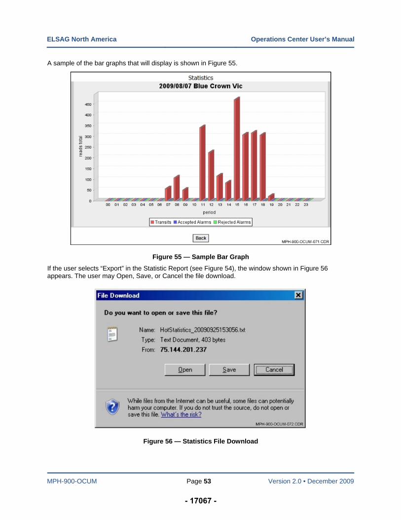
ELSAG North America Operations Center User’s Manual
MPH-900-OCUM Page 53 Version 2.0 • December 2009
A sample of the bar graphs that will display is shown in Figure 55.
Figure 55 — Sample Bar Graph
If the user selects “Export” in the Statistic Report (see Figure 54), the window shown in Figure 56 appears. The user may Open, Save, or Cancel the file download.
Figure 56 — Statistics File Download
- 17067 -

MPH-900-OCUM Page 54 Version 2.0 • December 2009
Chapter 6 — Hot List Management
Introduction
The features in this group are for use by System Administrators, Maintenance, and Manage Alarms personnel only. The available Query/Statistics functions explained in this chapter are as follows:
Export Hot List
Insert Delete HL (Hot List)
Show Hot List
Hot List Import Status
Post Hit Analysis
Hot List Import Status History
Import Extern HL (Hot List), and
Import local HL (Hot List).
Export Hot List
When Export Hot List is selected, the shown in Figure 57 appears. The current hot list in the system can be exported to a file.
Figure 57 — Export Hot List Screen
Referring to Figure 58, when the diskette icon is selected the Export Hot List File Download Dialog Box appears. At the same time the message “Wait please...” appears behind the dialog box. The Hot list is exported as a text file with the file extension “.txt.”
- 17068 -
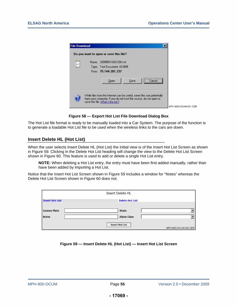
ELSAG North America Operations Center User’s Manual
MPH-900-OCUM Page 55 Version 2.0 • December 2009
Figure 58 — Export Hot List File Download Dialog Box
The Hot List file format is ready to be manually loaded into a Car System. The purpose of the function is to generate a loadable Hot List file to be used when the wireless links to the cars are down.
Insert Delete HL (Hot List)
When the user selects Insert Delete HL (Hot List) the initial view is of the Insert Hot List Screen as shown in Figure 59. Clicking in the Delete Hot List heading will change the view to the Delete Hot List Screen shown in Figure 60. This feature is used to add or delete a single Hot List entry.
NOTE: When deleting a Hot List entry, the entry must have been first added manually, rather than have been added by importing a Hot List.
Notice that the Insert Hot List Screen shown in Figure 59 includes a window for “Notes” whereas the Delete Hot List Screen shown in Figure 60 does not.
Figure 59 — Insert Delete HL (Hot List) — Insert Hot List Screen
- 17069 -
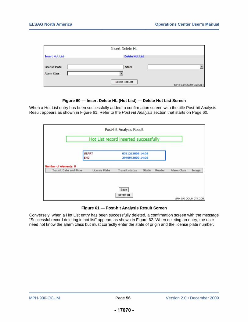
ELSAG North America Operations Center User’s Manual
MPH-900-OCUM Page 56 Version 2.0 • December 2009
Figure 60 — Insert Delete HL (Hot List) — Delete Hot List Screen
When a Hot List entry has been successfully added, a confirmation screen with the title Post-hit Analysis Result appears as shown in Figure 61. Refer to the Post Hit Analysis section that starts on Page 60.
Figure 61 — Post-hit Analysis Result Screen
Conversely, when a Hot List entry has been successfully deleted, a confirmation screen with the message “Successful record deleting in hot list” appears as shown in Figure 62. When deleting an entry, the user need not know the alarm class but must correctly enter the state of origin and the license plate number.
- 17070 -
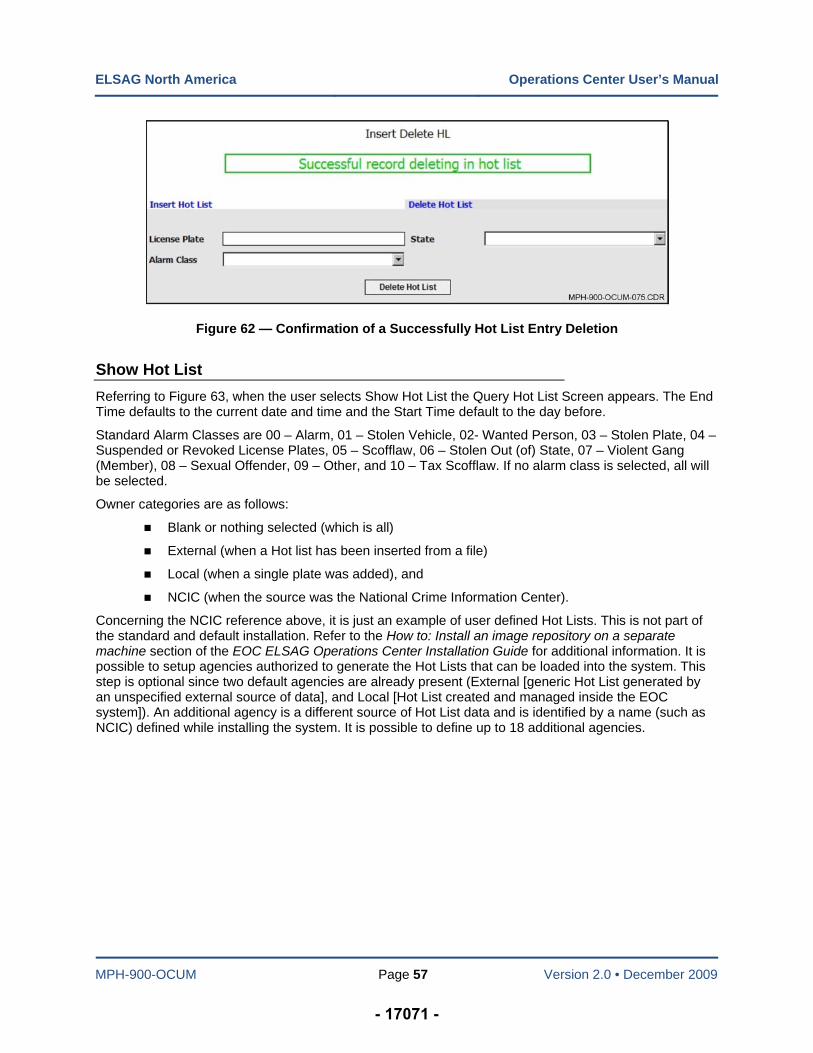
ELSAG North America Operations Center User’s Manual
MPH-900-OCUM Page 57 Version 2.0 • December 2009
Figure 62 — Confirmation of a Successfully Hot List Entry Deletion
Show Hot List
Referring to Figure 63, when the user selects Show Hot List the Query Hot List Screen appears. The End Time defaults to the current date and time and the Start Time default to the day before.
Standard Alarm Classes are 00 – Alarm, 01 – Stolen Vehicle, 02- Wanted Person, 03 – Stolen Plate, 04 – Suspended or Revoked License Plates, 05 – Scofflaw, 06 – Stolen Out (of) State, 07 – Violent Gang (Member), 08 – Sexual Offender, 09 – Other, and 10 – Tax Scofflaw. If no alarm class is selected, all will be selected.
Owner categories are as follows:
Blank or nothing selected (which is all)
External (when a Hot list has been inserted from a file)
Local (when a single plate was added), and
NCIC (when the source was the National Crime Information Center).
Concerning the NCIC reference above, it is just an example of user defined Hot Lists. This is not part of the standard and default installation. Refer to the How to: Install an image repository on a separate machine section of the EOC ELSAG Operations Center Installation Guide for additional information. It is possible to setup agencies authorized to generate the Hot Lists that can be loaded into the system. This step is optional since two default agencies are already present (External [generic Hot List generated by an unspecified external source of data], and Local [Hot List created and managed inside the EOC system]). An additional agency is a different source of Hot List data and is identified by a name (such as NCIC) defined while installing the system. It is possible to define up to 18 additional agencies.
- 17071 -
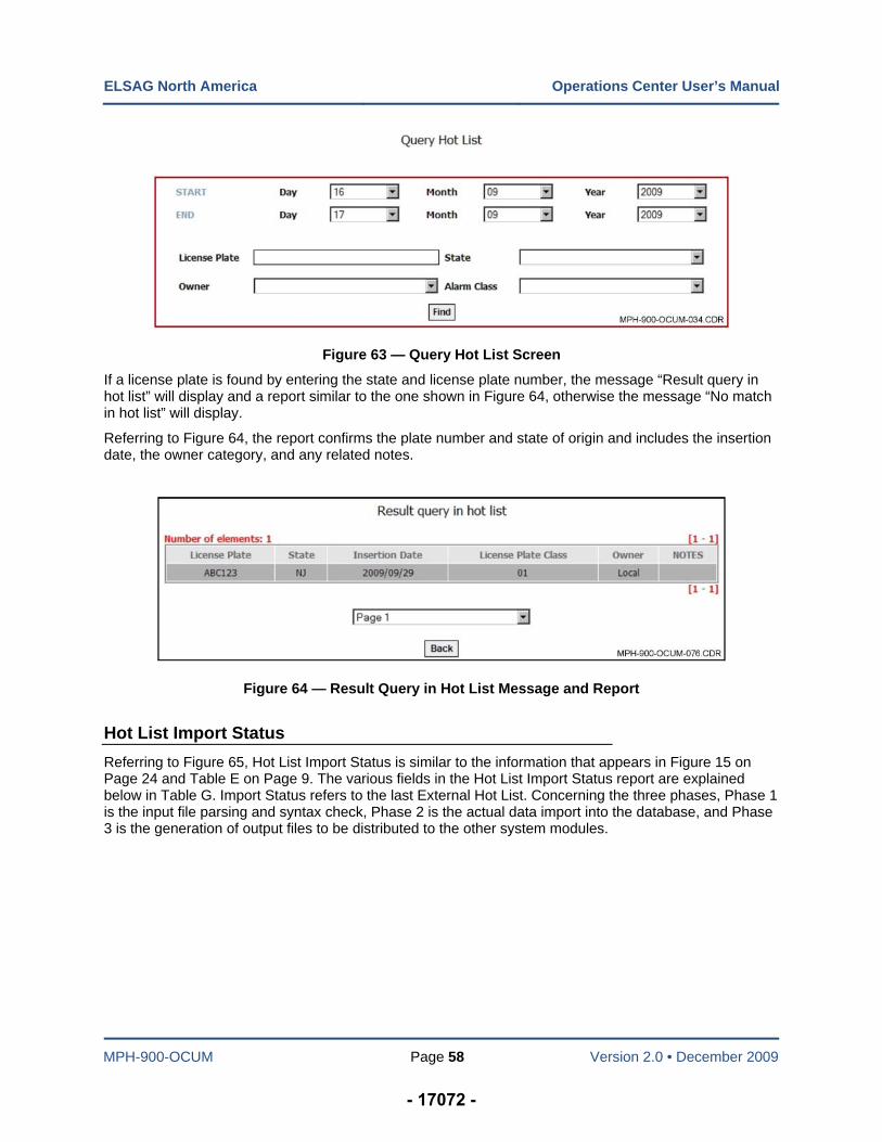
ELSAG North America Operations Center User’s Manual
MPH-900-OCUM Page 58 Version 2.0 • December 2009
Figure 63 — Query Hot List Screen
If a license plate is found by entering the state and license plate number, the message “Result query in hot list” will display and a report similar to the one shown in Figure 64, otherwise the message “No match in hot list” will display.
Referring to Figure 64, the report confirms the plate number and state of origin and includes the insertion date, the owner category, and any related notes.
Figure 64 — Result Query in Hot List Message and Report
Hot List Import Status
Referring to Figure 65, Hot List Import Status is similar to the information that appears in Figure 15 on Page 24 and Table E on Page 9. The various fields in the Hot List Import Status report are explained below in Table G. Import Status refers to the last External Hot List. Concerning the three phases, Phase 1 is the input file parsing and syntax check, Phase 2 is the actual data import into the database, and Phase 3 is the generation of output files to be distributed to the other system modules.
- 17072 -
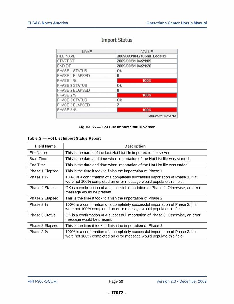
ELSAG North America Operations Center User’s Manual
MPH-900-OCUM Page 59 Version 2.0 • December 2009
Figure 65 — Hot List Import Status Screen
Table G — Hot List Import Status Report
Field Name Description
File Name This is the name of the last Hot List file imported to the server.
Start Time This is the date and time when importation of the Hot List file was started.
End Time This is the date and time when importation of the Hot List file was ended.
Phase 1 Elapsed This is the time it took to finish the importation of Phase 1.
Phase 1 % 100% is a confirmation of a completely successful importation of Phase 1. If it were not 100% completed an error message would populate this field.
Phase 2 Status OK is a confirmation of a successful importation of Phase 2. Otherwise, an error message would be present.
Phase 2 Elapsed This is the time it took to finish the importation of Phase 2.
Phase 2 % 100% is a confirmation of a completely successful importation of Phase 2. If it were not 100% completed an error message would populate this field.
Phase 3 Status OK is a confirmation of a successful importation of Phase 3. Otherwise, an error message would be present.
Phase 3 Elapsed This is the time it took to finish the importation of Phase 3.
Phase 3 % 100% is a confirmation of a completely successful importation of Phase 3. If it were not 100% completed an error message would populate this field.
- 17073 -
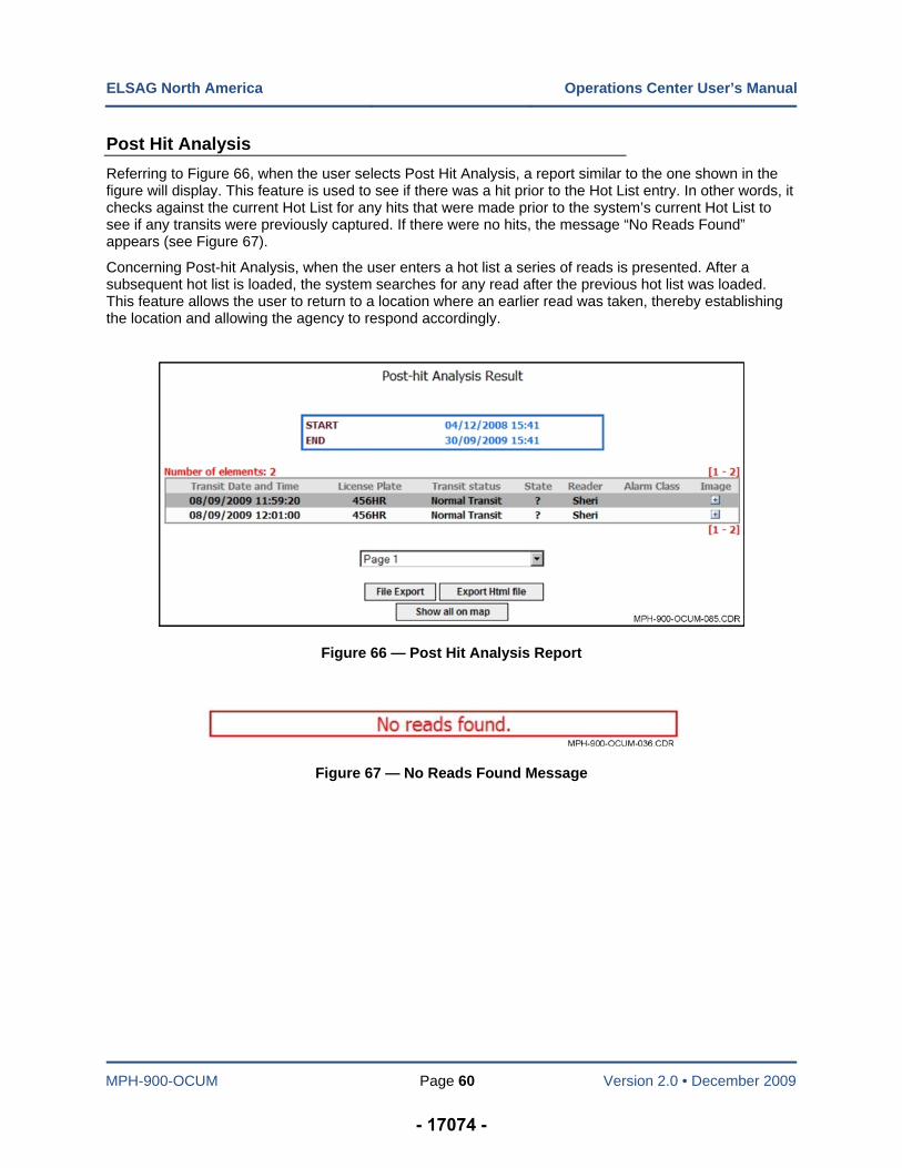
ELSAG North America Operations Center User’s Manual
MPH-900-OCUM Page 60 Version 2.0 • December 2009
Post Hit Analysis
Referring to Figure 66, when the user selects Post Hit Analysis, a report similar to the one shown in the figure will display. This feature is used to see if there was a hit prior to the Hot List entry. In other words, it checks against the current Hot List for any hits that were made prior to the system’s current Hot List to see if any transits were previously captured. If there were no hits, the message “No Reads Found” appears (see Figure 67).
Concerning Post-hit Analysis, when the user enters a hot list a series of reads is presented. After a subsequent hot list is loaded, the system searches for any read after the previous hot list was loaded. This feature allows the user to return to a location where an earlier read was taken, thereby establishing the location and allowing the agency to respond accordingly.
Figure 66 — Post Hit Analysis Report
Figure 67 — No Reads Found Message
- 17074 -
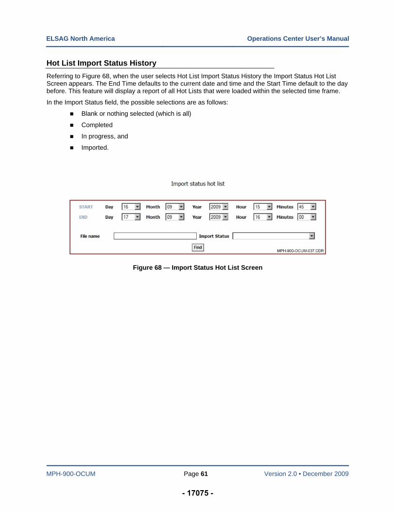
ELSAG North America Operations Center User’s Manual
MPH-900-OCUM Page 61 Version 2.0 • December 2009
Hot List Import Status History
Referring to Figure 68, when the user selects Hot List Import Status History the Import Status Hot List Screen appears. The End Time defaults to the current date and time and the Start Time default to the day before. This feature will display a report of all Hot Lists that were loaded within the selected time frame.
In the Import Status field, the possible selections are as follows:
Blank or nothing selected (which is all)
Completed
In progress, and
Imported.
Figure 68 — Import Status Hot List Screen
- 17075 -
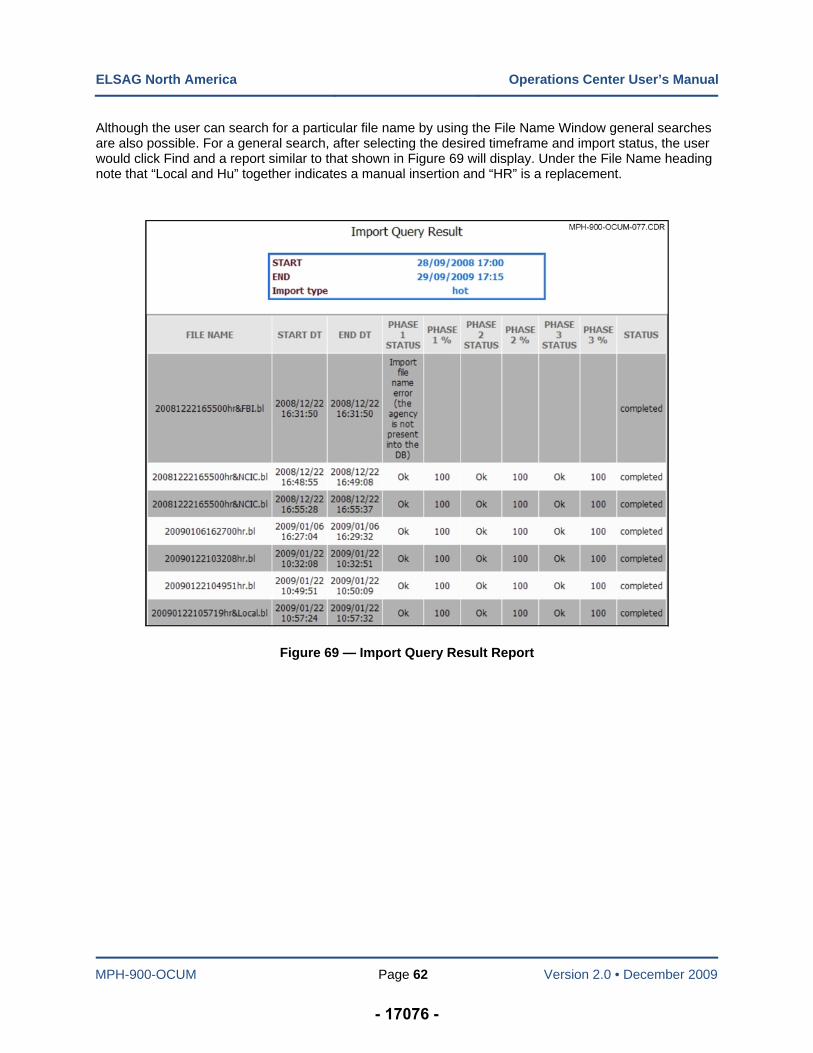
ELSAG North America Operations Center User’s Manual
MPH-900-OCUM Page 62 Version 2.0 • December 2009
Although the user can search for a particular file name by using the File Name Window general searches are also possible. For a general search, after selecting the desired timeframe and import status, the user would click Find and a report similar to that shown in Figure 69 will display. Under the File Name heading note that “Local and Hu” together indicates a manual insertion and “HR” is a replacement.
Figure 69 — Import Query Result Report
- 17076 -
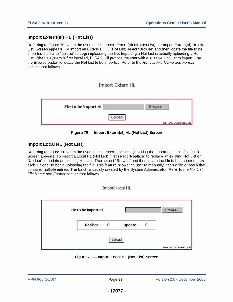
ELSAG North America Operations Center User’s Manual
MPH-900-OCUM Page 63 Version 2.0 • December 2009
Import Extern(al) HL (Hot List)
Referring to Figure 70, when the user selects Import Extern(al) HL (Hot List) the Import Extern(al) HL (Hot List) Screen appears. To import an Extern(al) HL (Hot List) select “Browse” and then locate the file to be imported then click “upload” to begin uploading the file. Importing a Hot List is actually uploading a Hot List. When a system is first installed, ELSAG will provide the user with a suitable Hot List to import. Use the Browse button to locate the Hot List to be imported. Refer to the Hot List File Name and Format section that follows.
Figure 70 — Import Extern(al) HL (Hot List) Screen
Import Local HL (Hot List)
Referring to Figure 71, when the user selects Import Local HL (Hot List) the Import Local HL (Hot List) Screen appears. To import a Local HL (Hot List), first select “Replace” to replace an existing Hot List or “Update” to update an existing Hot List. Then select “Browse” and then locate the file to be imported then click “upload” to begin uploading the file. This feature allows the user to manually insert a file or batch that contains multiple entries. The batch is usually created by the System Administrator. Refer to the Hot List File Name and Format section that follows.
Figure 71 — Import Local HL (Hot List) Screen
- 17077 -
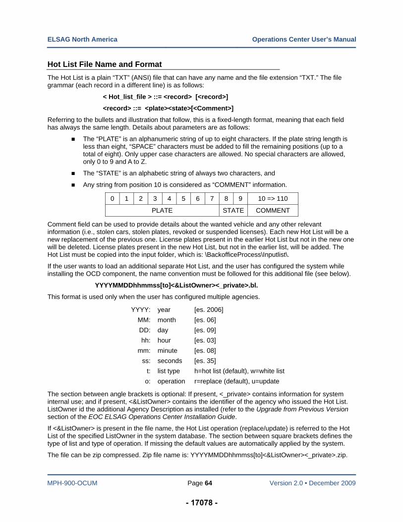
ELSAG North America Operations Center User’s Manual
MPH-900-OCUM Page 64 Version 2.0 • December 2009
Hot List File Name and Format
The Hot List is a plain “TXT” (ANSI) file that can have any name and the file extension “TXT.” The file grammar (each record in a different line) is as follows:
< Hot_list_file > ::= <record> [<record>]
<record> ::= <plate><state>[<Comment>]
Referring to the bullets and illustration that follow, this is a fixed-length format, meaning that each field has always the same length. Details about parameters are as follows:
The “PLATE” is an alphanumeric string of up to eight characters. If the plate string length is less than eight, “SPACE” characters must be added to fill the remaining positions (up to a total of eight). Only upper case characters are allowed. No special characters are allowed, only 0 to 9 and A to Z.
The “STATE” is an alphabetic string of always two characters, and
Any string from position 10 is considered as “COMMENT” information.
0 1 2 3 4 5 6 7 8 9 10 => 110
PLATE STATE COMMENT
Comment field can be used to provide details about the wanted vehicle and any other relevant information (i.e., stolen cars, stolen plates, revoked or suspended licenses). Each new Hot List will be a new replacement of the previous one. License plates present in the earlier Hot List but not in the new one will be deleted. License plates present in the new Hot List, but not in the earlier list, will be added. The Hot List must be copied into the input folder, which is: \BackofficeProcess\Inputlist\.
If the user wants to load an additional separate Hot List, and the user has configured the system while installing the OCD component, the name convention must be followed for this additional file (see below).
YYYYMMDDhhmmss[to]<&ListOwner><_private>.bl.
This format is used only when the user has configured multiple agencies.
YYYY: year [es. 2006]
MM: month [es. 06]
DD: day [es. 09]
hh: hour [es. 03]
mm: minute [es. 08]
ss: seconds [es. 35]
t: list type h=hot list (default), w=white list
o: operation r=replace (default), u=update
The section between angle brackets is optional: If present, <_private> contains information for system internal use; and if present, <&ListOwner> contains the identifier of the agency who issued the Hot List. ListOwner id the additional Agency Description as installed (refer to the Upgrade from Previous Version section of the EOC ELSAG Operations Center Installation Guide.
If <&ListOwner> is present in the file name, the Hot List operation (replace/update) is referred to the Hot List of the specified ListOwner in the system database. The section between square brackets defines the type of list and type of operation. If missing the default values are automatically applied by the system.
The file can be zip compressed. Zip file name is: YYYYMMDDhhmmss[to]<&ListOwner><_private>.zip.
- 17078 -
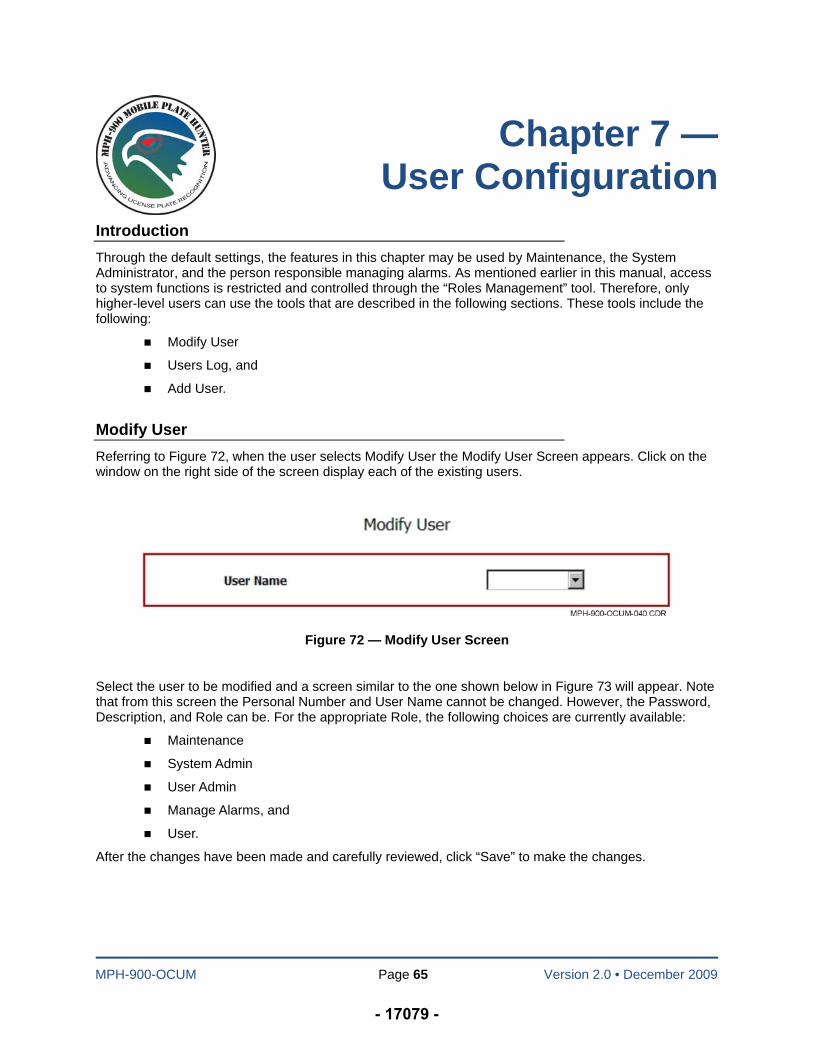
MPH-900-OCUM Page 65 Version 2.0 • December 2009
Chapter 7 — User Configuration
Introduction
Through the default settings, the features in this chapter may be used by Maintenance, the System Administrator, and the person responsible managing alarms. As mentioned earlier in this manual, access to system functions is restricted and controlled through the “Roles Management” tool. Therefore, only higher-level users can use the tools that are described in the following sections. These tools include the following:
Modify User
Users Log, and
Add User.
Modify User
Referring to Figure 72, when the user selects Modify User the Modify User Screen appears. Click on the window on the right side of the screen display each of the existing users.
Figure 72 — Modify User Screen
Select the user to be modified and a screen similar to the one shown below in Figure 73 will appear. Note that from this screen the Personal Number and User Name cannot be changed. However, the Password, Description, and Role can be. For the appropriate Role, the following choices are currently available:
Maintenance
System Admin
User Admin
Manage Alarms, and
User.
After the changes have been made and carefully reviewed, click “Save” to make the changes.
- 17079 -
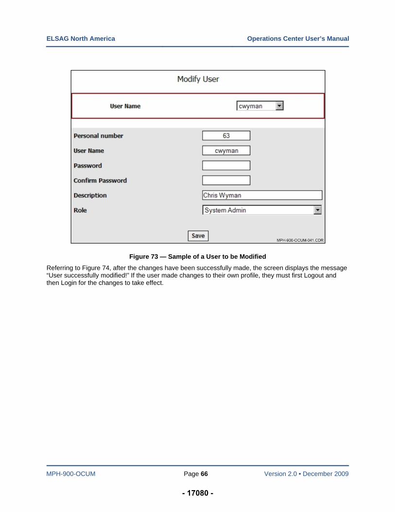
ELSAG North America Operations Center User’s Manual
MPH-900-OCUM Page 66 Version 2.0 • December 2009
Figure 73 — Sample of a User to be Modified
Referring to Figure 74, after the changes have been successfully made, the screen displays the message “User successfully modified!” If the user made changes to their own profile, they must first Logout and then Login for the changes to take effect.
- 17080 -
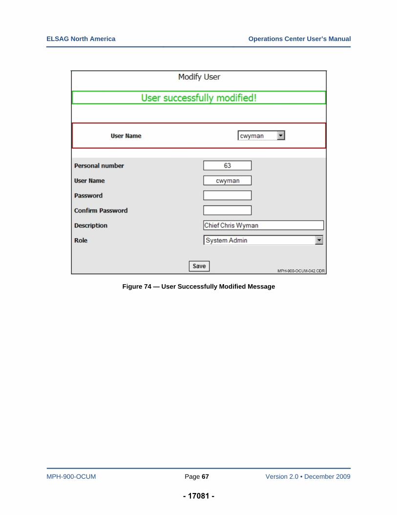
ELSAG North America Operations Center User’s Manual
MPH-900-OCUM Page 67 Version 2.0 • December 2009
Figure 74 — User Successfully Modified Message
- 17081 -
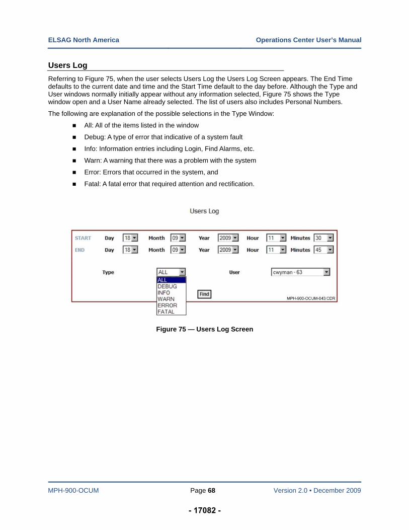
ELSAG North America Operations Center User’s Manual
MPH-900-OCUM Page 68 Version 2.0 • December 2009
Users Log
Referring to Figure 75, when the user selects Users Log the Users Log Screen appears. The End Time defaults to the current date and time and the Start Time default to the day before. Although the Type and User windows normally initially appear without any information selected, Figure 75 shows the Type window open and a User Name already selected. The list of users also includes Personal Numbers.
The following are explanation of the possible selections in the Type Window:
All: All of the items listed in the window
Debug: A type of error that indicative of a system fault
Info: Information entries including Login, Find Alarms, etc.
Warn: A warning that there was a problem with the system
Error: Errors that occurred in the system, and
Fatal: A fatal error that required attention and rectification.
Figure 75 — Users Log Screen
- 17082 -
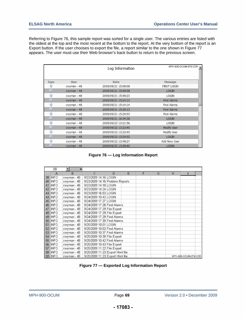
ELSAG North America Operations Center User’s Manual
MPH-900-OCUM Page 69 Version 2.0 • December 2009
Referring to Figure 76, this sample report was sorted for a single user. The various entries are listed with the oldest at the top and the most recent at the bottom to the report. At the very bottom of the report is an Export button. If the user chooses to export the file, a report similar to the one shown in Figure 77 appears. The user must use their Web browser’s back button to return to the previous screen.
Figure 76 — Log Information Report
Figure 77 — Exported Log Information Report
- 17083 -
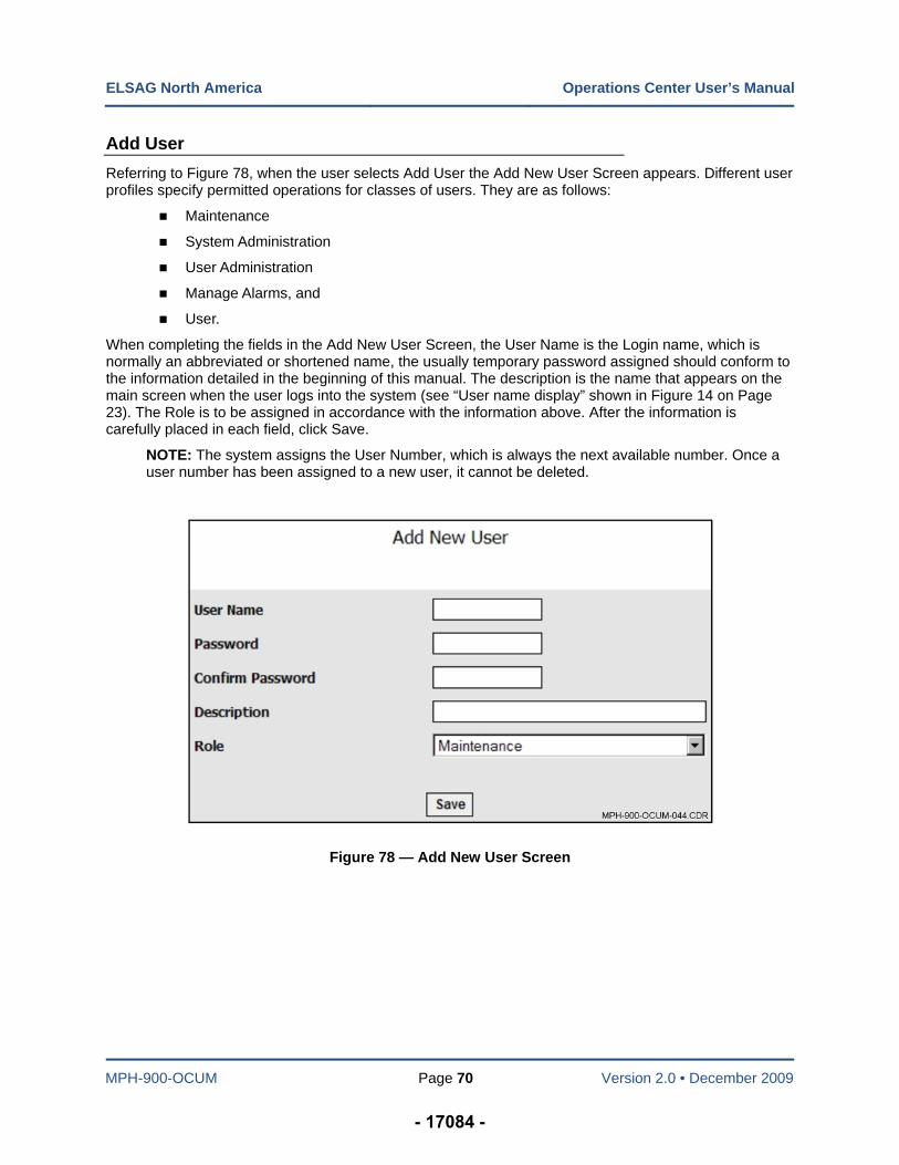
ELSAG North America Operations Center User’s Manual
MPH-900-OCUM Page 70 Version 2.0 • December 2009
Add User
Referring to Figure 78, when the user selects Add User the Add New User Screen appears. Different user profiles specify permitted operations for classes of users. They are as follows:
Maintenance
System Administration
User Administration
Manage Alarms, and
User.
When completing the fields in the Add New User Screen, the User Name is the Login name, which is normally an abbreviated or shortened name, the usually temporary password assigned should conform to the information detailed in the beginning of this manual. The description is the name that appears on the main screen when the user logs into the system (see “User name display” shown in Figure 14 on Page 23). The Role is to be assigned in accordance with the information above. After the information is carefully placed in each field, click Save.
NOTE: The system assigns the User Number, which is always the next available number. Once a user number has been assigned to a new user, it cannot be deleted.
Figure 78 — Add New User Screen
- 17084 -
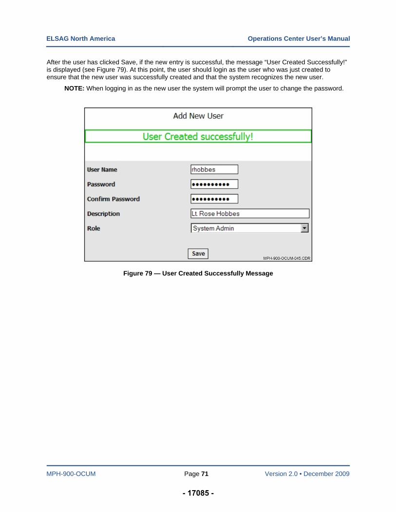
ELSAG North America Operations Center User’s Manual
MPH-900-OCUM Page 71 Version 2.0 • December 2009
After the user has clicked Save, if the new entry is successful, the message “User Created Successfully!” is displayed (see Figure 79). At this point, the user should login as the user who was just created to ensure that the new user was successfully created and that the system recognizes the new user.
NOTE: When logging in as the new user the system will prompt the user to change the password.
Figure 79 — User Created Successfully Message
- 17085 -
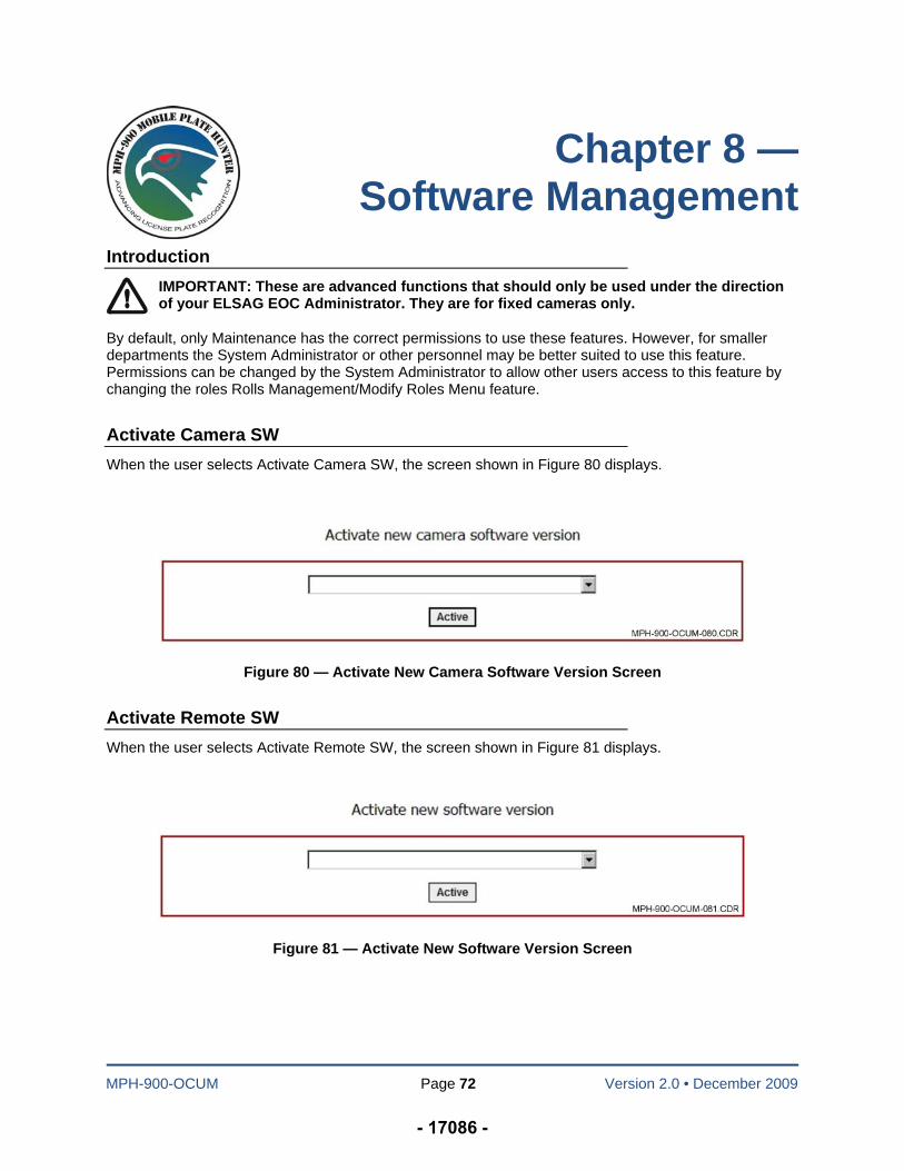
MPH-900-OCUM Page 72 Version 2.0 • December 2009
Chapter 8 — Software Management
Introduction
IMPORTANT: These are advanced functions that should only be used under the direction of your ELSAG EOC Administrator. They are for fixed cameras only.
By default, only Maintenance has the correct permissions to use these features. However, for smaller departments the System Administrator or other personnel may be better suited to use this feature. Permissions can be changed by the System Administrator to allow other users access to this feature by changing the roles Rolls Management/Modify Roles Menu feature.
Activate Camera SW
When the user selects Activate Camera SW, the screen shown in Figure 80 displays.
Figure 80 — Activate New Camera Software Version Screen
Activate Remote SW
When the user selects Activate Remote SW, the screen shown in Figure 81 displays.
Figure 81 — Activate New Software Version Screen
- 17086 -
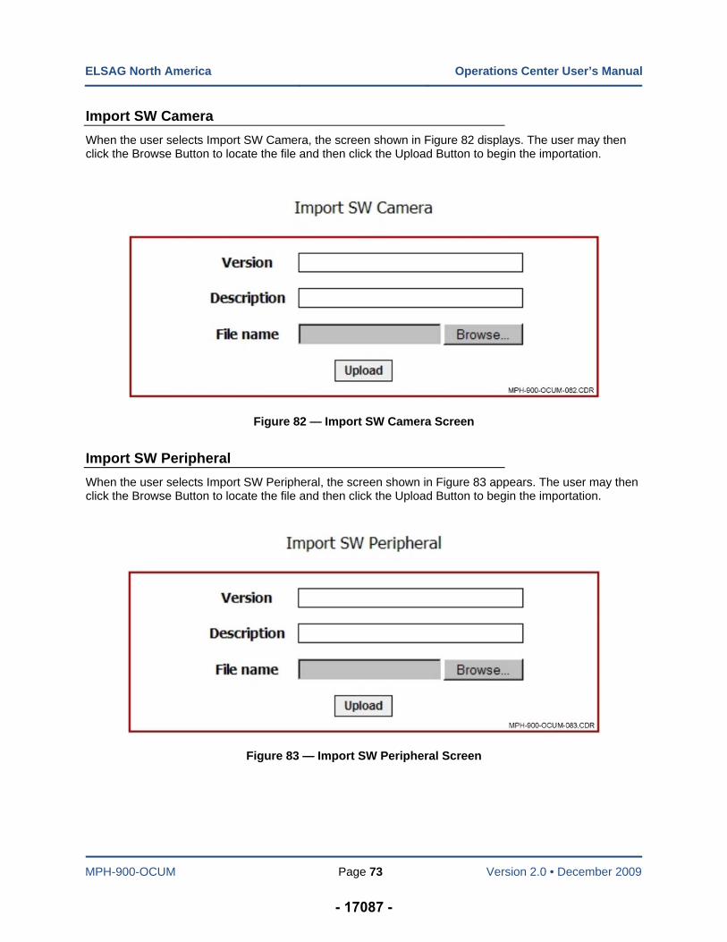
ELSAG North America Operations Center User’s Manual
MPH-900-OCUM Page 73 Version 2.0 • December 2009
Import SW Camera
When the user selects Import SW Camera, the screen shown in Figure 82 displays. The user may then click the Browse Button to locate the file and then click the Upload Button to begin the importation.
Figure 82 — Import SW Camera Screen
Import SW Peripheral
When the user selects Import SW Peripheral, the screen shown in Figure 83 appears. The user may then click the Browse Button to locate the file and then click the Upload Button to begin the importation.
Figure 83 — Import SW Peripheral Screen
- 17087 -
MPH-900-OCUM Page 74 Version 2.0 • December 2009
Chapter 9 — Data Mining
Introduction
By default, only the System Administrator has the correct permissions to use these features. The available Data Mining functions explained in this chapter are Cross Search, and Nested & Convoy Search.
Cross Search
This function allows the user to cross check reads from two separate queries and determines “uniques” and duplicates. “Uniques” are reads (plate numbers) that are present in one query data set only. Duplicates are reads that are present in both data sets. The function is broken down into three sequential steps:
In the first step, the first query parameters of the first data set are defined (this is like any other query, including cartographic criteria).
In the second step, the second data set is defined.
In the third step, uniques or duplicates are selected.
The purpose of the function is to compare reads of the same area at different times. In this way, by checking the same parking lot for example on two different days, it is possible to roughly separate residents from visitors
Cross Search Step 1
When Cross Search is selected, the Cross Search Step 1 Screen shown in Figure 84 appears. The End Time defaults to the current date and time and the Start Time default to the day before.
The Reader section of the screen lists all readers in alphabetical order and the Transit Status is listed in the order shown in the figure. Standard Alarm Classes are 00 – Alarm, 01 – Stolen Vehicle, 02- Wanted Person, 03 – Stolen Plate, 04 – Suspended or Revoked License Plates, 05 – Scofflaw, 06 – Stolen Out (of) State, 07 – Violent Gang (Member), 08 – Sexual Offender, 09 – Other, and 10 – Tax Scofflaw. If no alarm class is selected, all will be selected.
The Reader Window lists each of the vehicles and fixed cameras that are part of the system. The Transit Status Window includes the following categories:
Deferred Alarm (alarm that timed out at the user end and no action was taken against it)
Expired Alarm (alarm that was expired by the system, expiration time for a deferred alarm)
Rejected Alarm (alarm that was rejected the user)
Normal Transit (regular read from the vehicle or fixed camera)
Pending Alarm (pending acknowledgement by the end user [usually fixed camera]), and
Accepted Alarm (alarm that was accepted by the user).
- 17088 -
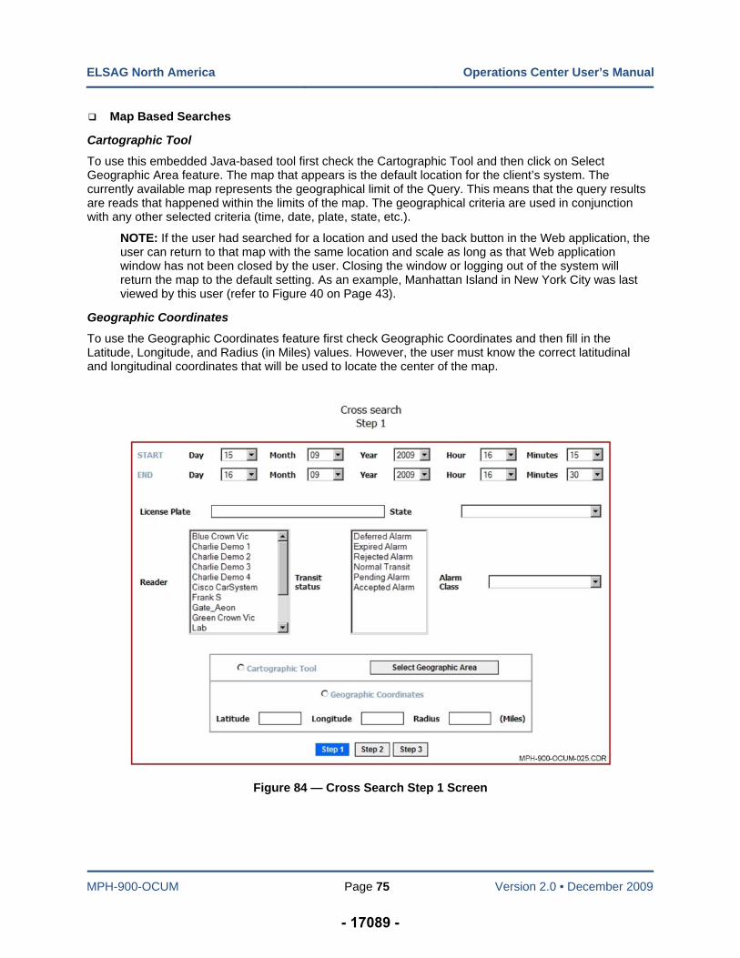
ELSAG North America Operations Center User’s Manual
MPH-900-OCUM Page 75 Version 2.0 • December 2009
Map Based Searches
Cartographic Tool
To use this embedded Java-based tool first check the Cartographic Tool and then click on Select Geographic Area feature. The map that appears is the default location for the client’s system. The currently available map represents the geographical limit of the Query. This means that the query results are reads that happened within the limits of the map. The geographical criteria are used in conjunction with any other selected criteria (time, date, plate, state, etc.).
NOTE: If the user had searched for a location and used the back button in the Web application, the user can return to that map with the same location and scale as long as that Web application window has not been closed by the user. Closing the window or logging out of the system will return the map to the default setting. As an example, Manhattan Island in New York City was last viewed by this user (refer to Figure 40 on Page 43).
Geographic Coordinates
To use the Geographic Coordinates feature first check Geographic Coordinates and then fill in the Latitude, Longitude, and Radius (in Miles) values. However, the user must know the correct latitudinal and longitudinal coordinates that will be used to locate the center of the map.
Figure 84 — Cross Search Step 1 Screen
- 17089 -
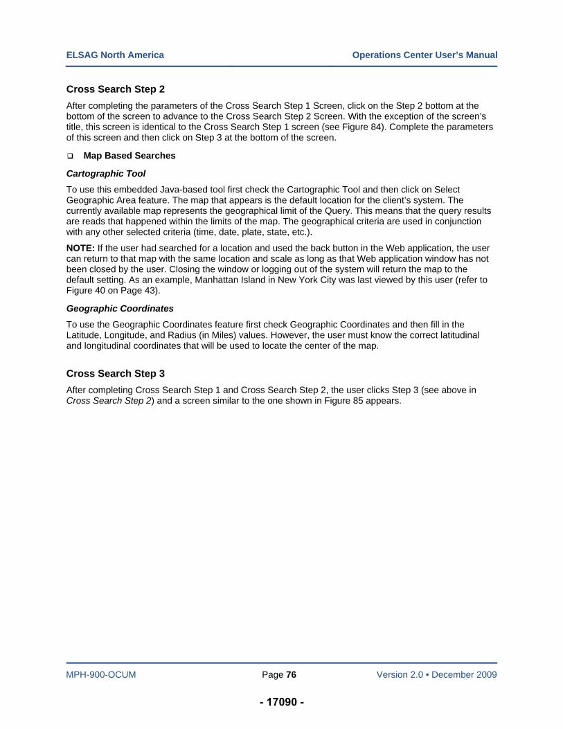
ELSAG North America Operations Center User’s Manual
MPH-900-OCUM Page 76 Version 2.0 • December 2009
Cross Search Step 2
After completing the parameters of the Cross Search Step 1 Screen, click on the Step 2 bottom at the bottom of the screen to advance to the Cross Search Step 2 Screen. With the exception of the screen’s title, this screen is identical to the Cross Search Step 1 screen (see Figure 84). Complete the parameters of this screen and then click on Step 3 at the bottom of the screen.
Map Based Searches
Cartographic Tool
To use this embedded Java-based tool first check the Cartographic Tool and then click on Select Geographic Area feature. The map that appears is the default location for the client’s system. The currently available map represents the geographical limit of the Query. This means that the query results are reads that happened within the limits of the map. The geographical criteria are used in conjunction with any other selected criteria (time, date, plate, state, etc.).
NOTE: If the user had searched for a location and used the back button in the Web application, the user can return to that map with the same location and scale as long as that Web application window has not been closed by the user. Closing the window or logging out of the system will return the map to the default setting. As an example, Manhattan Island in New York City was last viewed by this user (refer to Figure 40 on Page 43).
Geographic Coordinates
To use the Geographic Coordinates feature first check Geographic Coordinates and then fill in the Latitude, Longitude, and Radius (in Miles) values. However, the user must know the correct latitudinal and longitudinal coordinates that will be used to locate the center of the map.
Cross Search Step 3
After completing Cross Search Step 1 and Cross Search Step 2, the user clicks Step 3 (see above in Cross Search Step 2) and a screen similar to the one shown in Figure 85 appears.
- 17090 -
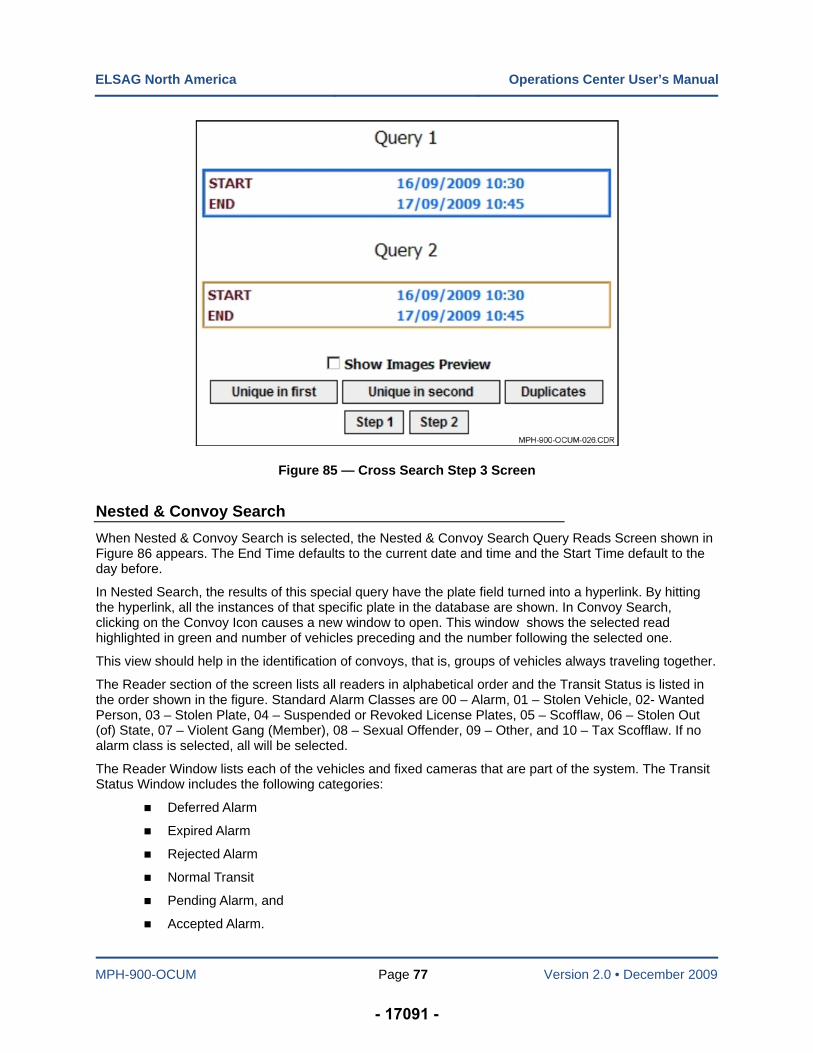
ELSAG North America Operations Center User’s Manual
MPH-900-OCUM Page 77 Version 2.0 • December 2009
Figure 85 — Cross Search Step 3 Screen
Nested & Convoy Search
When Nested & Convoy Search is selected, the Nested & Convoy Search Query Reads Screen shown in Figure 86 appears. The End Time defaults to the current date and time and the Start Time default to the day before.
In Nested Search, the results of this special query have the plate field turned into a hyperlink. By hitting the hyperlink, all the instances of that specific plate in the database are shown. In Convoy Search, clicking on the Convoy Icon causes a new window to open. This window shows the selected read highlighted in green and number of vehicles preceding and the number following the selected one.
This view should help in the identification of convoys, that is, groups of vehicles always traveling together.
The Reader section of the screen lists all readers in alphabetical order and the Transit Status is listed in the order shown in the figure. Standard Alarm Classes are 00 – Alarm, 01 – Stolen Vehicle, 02- Wanted Person, 03 – Stolen Plate, 04 – Suspended or Revoked License Plates, 05 – Scofflaw, 06 – Stolen Out (of) State, 07 – Violent Gang (Member), 08 – Sexual Offender, 09 – Other, and 10 – Tax Scofflaw. If no alarm class is selected, all will be selected.
The Reader Window lists each of the vehicles and fixed cameras that are part of the system. The Transit Status Window includes the following categories:
Deferred Alarm
Expired Alarm
Rejected Alarm
Normal Transit
Pending Alarm, and
Accepted Alarm.
- 17091 -
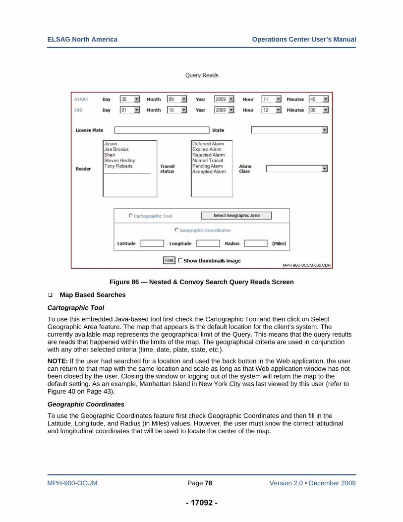
ELSAG North America Operations Center User’s Manual
MPH-900-OCUM Page 78 Version 2.0 • December 2009
Figure 86 — Nested & Convoy Search Query Reads Screen
Map Based Searches
Cartographic Tool
To use this embedded Java-based tool first check the Cartographic Tool and then click on Select Geographic Area feature. The map that appears is the default location for the client’s system. The currently available map represents the geographical limit of the Query. This means that the query results are reads that happened within the limits of the map. The geographical criteria are used in conjunction with any other selected criteria (time, date, plate, state, etc.).
NOTE: If the user had searched for a location and used the back button in the Web application, the user can return to that map with the same location and scale as long as that Web application window has not been closed by the user. Closing the window or logging out of the system will return the map to the default setting. As an example, Manhattan Island in New York City was last viewed by this user (refer to Figure 40 on Page 43).
Geographic Coordinates
To use the Geographic Coordinates feature first check Geographic Coordinates and then fill in the Latitude, Longitude, and Radius (in Miles) values. However, the user must know the correct latitudinal and longitudinal coordinates that will be used to locate the center of the map.
- 17092 -
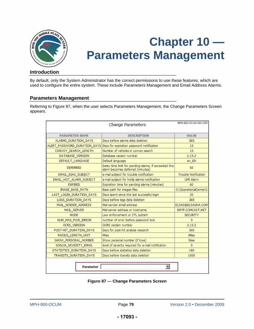
MPH-900-OCUM Page 79 Version 2.0 • December 2009
Chapter 10 — Parameters Management
Introduction
By default, only the System Administrator has the correct permissions to use these features, which are used to configure the entire system. These include Parameters Management and Email Address Alarms.
Parameters Management
Referring to Figure 87, when the user selects Parameters Management, the Change Parameters Screen appears.
Figure 87 — Change Parameters Screen
- 17093 -
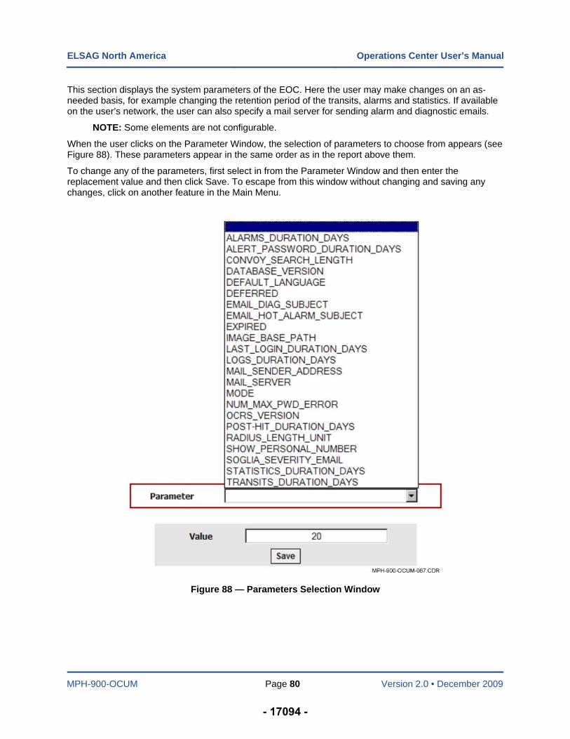
ELSAG North America Operations Center User’s Manual
MPH-900-OCUM Page 80 Version 2.0 • December 2009
This section displays the system parameters of the EOC. Here the user may make changes on an as-needed basis, for example changing the retention period of the transits, alarms and statistics. If available on the user’s network, the user can also specify a mail server for sending alarm and diagnostic emails.
NOTE: Some elements are not configurable.
When the user clicks on the Parameter Window, the selection of parameters to choose from appears (see Figure 88). These parameters appear in the same order as in the report above them.
To change any of the parameters, first select in from the Parameter Window and then enter the replacement value and then click Save. To escape from this window without changing and saving any changes, click on another feature in the Main Menu.
Figure 88 — Parameters Selection Window
- 17094 -
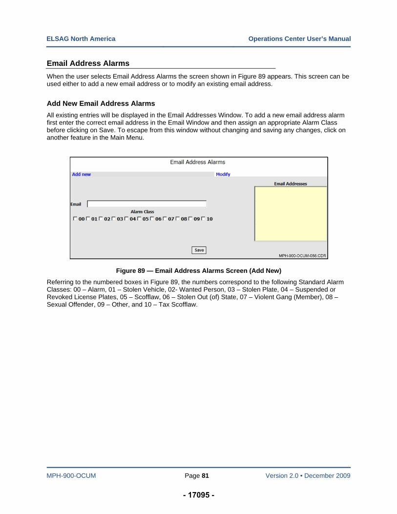
ELSAG North America Operations Center User’s Manual
MPH-900-OCUM Page 81 Version 2.0 • December 2009
Email Address Alarms
When the user selects Email Address Alarms the screen shown in Figure 89 appears. This screen can be used either to add a new email address or to modify an existing email address.
Add New Email Address Alarms
All existing entries will be displayed in the Email Addresses Window. To add a new email address alarm first enter the correct email address in the Email Window and then assign an appropriate Alarm Class before clicking on Save. To escape from this window without changing and saving any changes, click on another feature in the Main Menu.
Figure 89 — Email Address Alarms Screen (Add New)
Referring to the numbered boxes in Figure 89, the numbers correspond to the following Standard Alarm Classes: 00 – Alarm, 01 – Stolen Vehicle, 02- Wanted Person, 03 – Stolen Plate, 04 – Suspended or Revoked License Plates, 05 – Scofflaw, 06 – Stolen Out (of) State, 07 – Violent Gang (Member), 08 – Sexual Offender, 09 – Other, and 10 – Tax Scofflaw.
- 17095 -
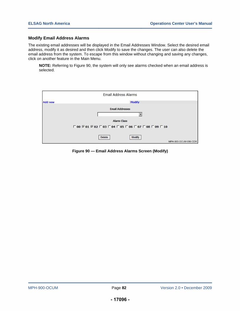
ELSAG North America Operations Center User’s Manual
MPH-900-OCUM Page 82 Version 2.0 • December 2009
Modify Email Address Alarms
The existing email addresses will be displayed in the Email Addresses Window. Select the desired email address, modify it as desired and then click Modify to save the changes. The user can also delete the email address from the system. To escape from this window without changing and saving any changes, click on another feature in the Main Menu.
NOTE: Referring to Figure 90, the system will only see alarms checked when an email address is selected.
Figure 90 — Email Address Alarms Screen (Modify)
- 17096 -
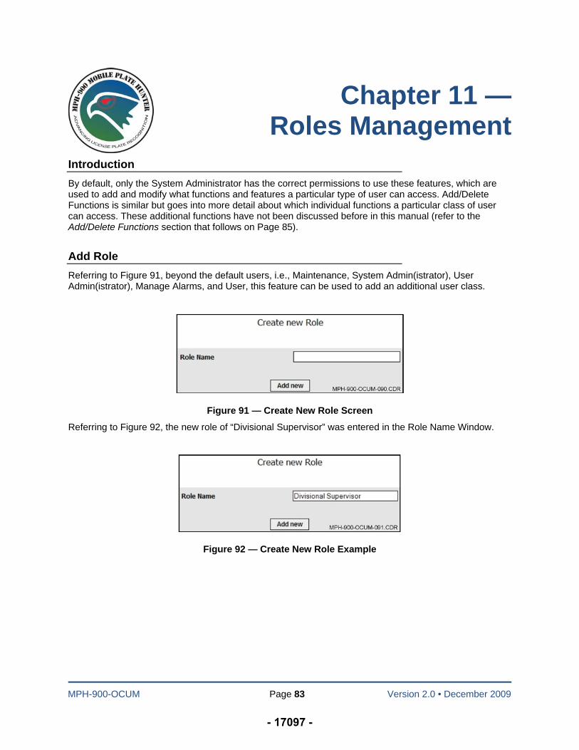
MPH-900-OCUM Page 83 Version 2.0 • December 2009
Chapter 11 — Roles Management
Introduction
By default, only the System Administrator has the correct permissions to use these features, which are used to add and modify what functions and features a particular type of user can access. Add/Delete Functions is similar but goes into more detail about which individual functions a particular class of user can access. These additional functions have not been discussed before in this manual (refer to the Add/Delete Functions section that follows on Page 85).
Add Role
Referring to Figure 91, beyond the default users, i.e., Maintenance, System Admin(istrator), User Admin(istrator), Manage Alarms, and User, this feature can be used to add an additional user class.
Figure 91 — Create New Role Screen
Referring to Figure 92, the new role of “Divisional Supervisor” was entered in the Role Name Window.
Figure 92 — Create New Role Example
- 17097 -
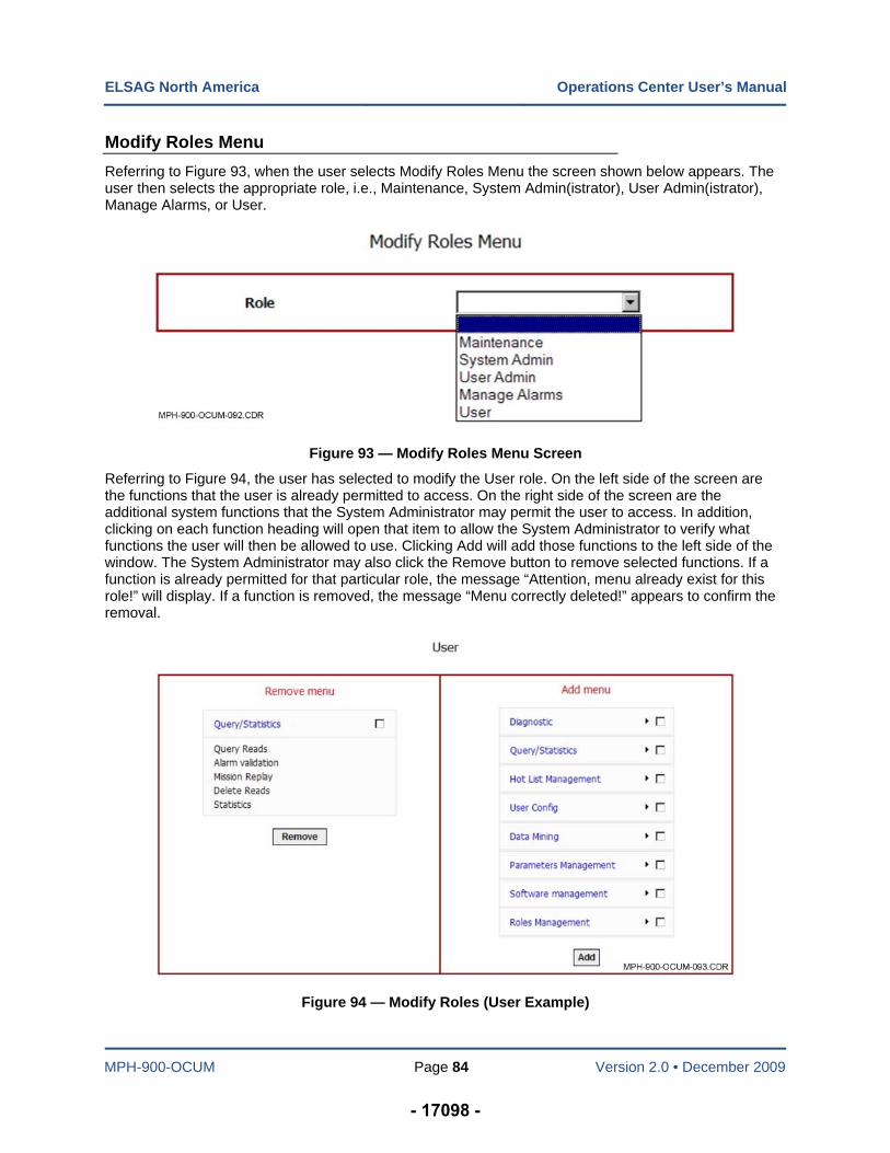
ELSAG North America Operations Center User’s Manual
MPH-900-OCUM Page 84 Version 2.0 • December 2009
Modify Roles Menu
Referring to Figure 93, when the user selects Modify Roles Menu the screen shown below appears. The user then selects the appropriate role, i.e., Maintenance, System Admin(istrator), User Admin(istrator), Manage Alarms, or User.
Figure 93 — Modify Roles Menu Screen
Referring to Figure 94, the user has selected to modify the User role. On the left side of the screen are the functions that the user is already permitted to access. On the right side of the screen are the additional system functions that the System Administrator may permit the user to access. In addition, clicking on each function heading will open that item to allow the System Administrator to verify what functions the user will then be allowed to use. Clicking Add will add those functions to the left side of the window. The System Administrator may also click the Remove button to remove selected functions. If a function is already permitted for that particular role, the message “Attention, menu already exist for this role!” will display. If a function is removed, the message “Menu correctly deleted!” appears to confirm the removal.
Figure 94 — Modify Roles (User Example)
- 17098 -
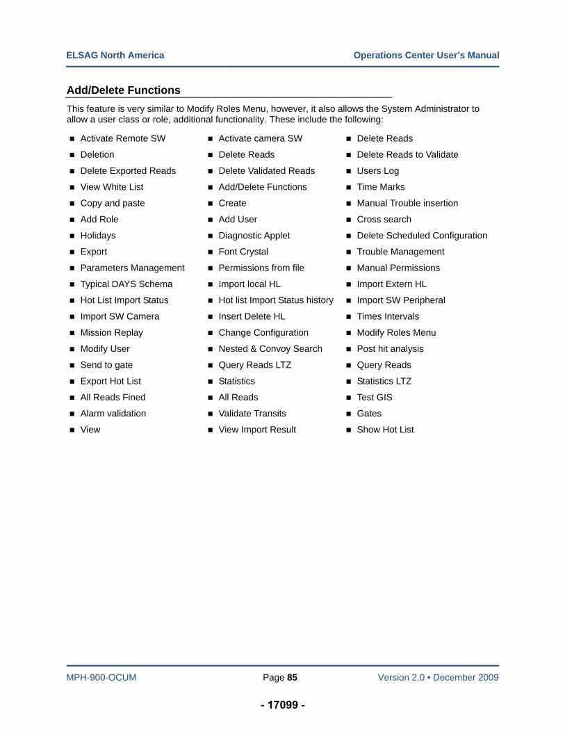
ELSAG North America Operations Center User’s Manual
MPH-900-OCUM Page 85 Version 2.0 • December 2009
Add/Delete Functions
This feature is very similar to Modify Roles Menu, however, it also allows the System Administrator to allow a user class or role, additional functionality. These include the following:
Activate Remote SW Activate camera SW Delete Reads
Deletion Delete Reads Delete Reads to Validate
Delete Exported Reads Delete Validated Reads Users Log
View White List Add/Delete Functions Time Marks
Copy and paste Create Manual Trouble insertion
Add Role Add User Cross search
Holidays Diagnostic Applet Delete Scheduled Configuration
Export Font Crystal Trouble Management
Parameters Management Permissions from file Manual Permissions
Typical DAYS Schema Import local HL Import Extern HL
Hot List Import Status Hot list Import Status history Import SW Peripheral
Import SW Camera Insert Delete HL Times Intervals
Mission Replay Change Configuration Modify Roles Menu
Modify User Nested & Convoy Search Post hit analysis
Send to gate Query Reads LTZ Query Reads
Export Hot List Statistics Statistics LTZ
All Reads Fined All Reads Test GIS
Alarm validation Validate Transits Gates
View View Import Result Show Hot List
- 17099 -
ELSAG North America Operations Center User’s Manual
MPH-900-OCUM Page 86 Version 2.0 • December 2009
NOTES:
- 17100 -

ELSAG North America Operations Center User’s Manual
MPH-900-OCUM Page 87 Version 2.0 • December 2009
NOTES:
- 17101 -
ELSAG North America Operations Center User’s Manual
MPH-900-OCUM Page 88 Version 2.0 • December 2009
- 17102 -