Embed Size (px)
Citation preview
1 Noise Countermeasures for Mobile Phones
Mobile phone functions have been expanding to point
where the original telephone function seems just and extra
feature. They have developed into mobile tools. Expanded
features such as cameras and high-resolution screens mean
that higher frequency signals are used, which creates harmonics
causing higher levels of noise in the communication frequency
band.
Several radio sending and receiving methods are
frequencies used for mobile phones. Mobile phones are
devices for sending and receiving radio waves, so noise from
the phone itself can become interfering waves that can
deteriorate performance. Devices themselves are compact, so
the noise source and the antenna for sending and receiving are
very close, within 10 cm. As a result, even a small level of noise
causes the input power to the antenna to become large.
This problem is directly related to reception sensitivity, so it
is not a serious problem in locations where there is a strong
radio wave. However, it can be impossible to receive a signal in
locations where the radio wave is weak.
To resolve this issue, noise suppression components can
be added to signal lines on the baseplate where the harmonics
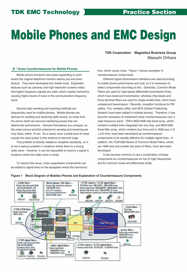
flow, which cause noise. Figure 1 shows examples of
countermeasure components.
Different signal transmission interfaces are used according
to mobile phone performance and cost, so it is necessary to
select components according to this. Generally, Common Mode
Filters are used for high-speed differential transmission lines,
which have balanced transmission, whereas chip beads and
three-terminal filters are used for single-ended lines, which have
unbalanced transmission. Recently, reception functions for FM
radios, TVs, wireless LANs, and GPS (Global Positioning
System) have been added to mobiles phones. Therefore, it has
become necessary to implement noise countermeasures over a
wide frequency band. TDK’s MZA1608 chip bead array, which
contains multiple lines integrated into one chip, and MEA1608
three-filter array, which contains four lines and is 1608 size (1.6
× 0.8 mm), have been developed as countermeasure
components to be equally effective for multiple signal lines. In
addition, the TCM1608 Series of Common Mode Filters, which
are 1608 size and contain two pairs of filters, have also been
developed.
It has become common to use a combination of these
components as countermeasures for low to high frequencies
and for common mode and differential mode.
Mobile Phones and EMC DesignTDK Corporation Magnetics Business Group
Masashi Orihara
TDK EMC Technology Practice Section
Figure 1 Block Diagram of Mobiles Phones and Explanation of Countermeasure Components
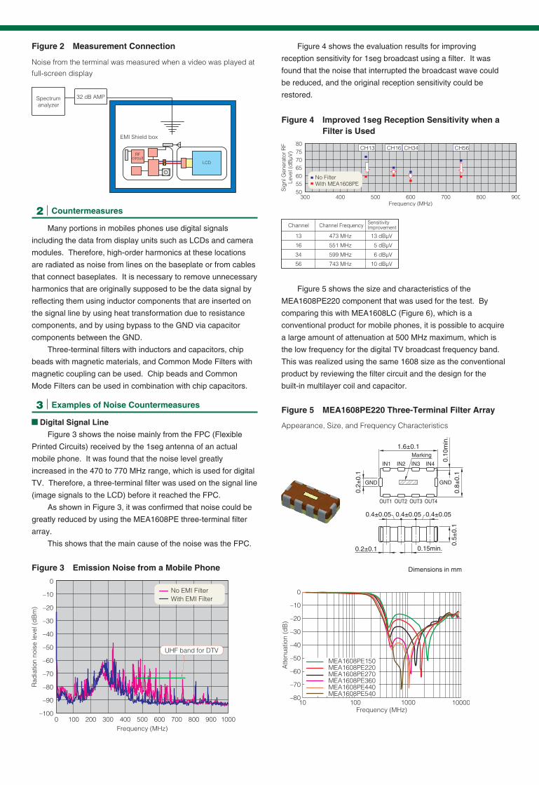
2 Countermeasures
Many portions in mobiles phones use digital signals
including the data from display units such as LCDs and camera
modules. Therefore, high-order harmonics at these locations
are radiated as noise from lines on the baseplate or from cables
that connect baseplates. It is necessary to remove unnecessary
harmonics that are originally supposed to be the data signal by
reflecting them using inductor components that are inserted on
the signal line by using heat transformation due to resistance
components, and by using bypass to the GND via capacitor
components between the GND.
Three-terminal filters with inductors and capacitors, chip
beads with magnetic materials, and Common Mode Filters with
magnetic coupling can be used. Chip beads and Common
Mode Filters can be used in combination with chip capacitors.
3 Examples of Noise Countermeasures
Digital Signal Line
Figure 3 shows the noise mainly from the FPC (Flexible
Printed Circuits) received by the 1seg antenna of an actual
mobile phone. It was found that the noise level greatly
increased in the 470 to 770 MHz range, which is used for digital
TV. Therefore, a three-terminal filter was used on the signal line
(image signals to the LCD) before it reached the FPC.
As shown in Figure 3, it was confirmed that noise could be
greatly reduced by using the MEA1608PE three-terminal filter
array.
This shows that the main cause of the noise was the FPC.
Figure 4 shows the evaluation results for improving
reception sensitivity for 1seg broadcast using a filter. It was
found that the noise that interrupted the broadcast wave could
be reduced, and the original reception sensitivity could be
restored.
Figure 5 shows the size and characteristics of the
MEA1608PE220 component that was used for the test. By
comparing this with MEA1608LC (Figure 6), which is a
conventional product for mobile phones, it is possible to acquire
a large amount of attenuation at 500 MHz maximum, which is
the low frequency for the digital TV broadcast frequency band.
This was realized using the same 1608 size as the conventional
product by reviewing the filter circuit and the design for the
built-in multilayer coil and capacitor.
Figure 3 Emission Noise from a Mobile Phone
Figure 4 Improved 1seg Reception Sensitivity when a Filter is Used
Figure 2 Measurement Connection
Figure 5 MEA1608PE220 Three-Terminal Filter Array
Noise from the terminal was measured when a video was played at full-screen display
Appearance, Size, and Frequency Characteristics
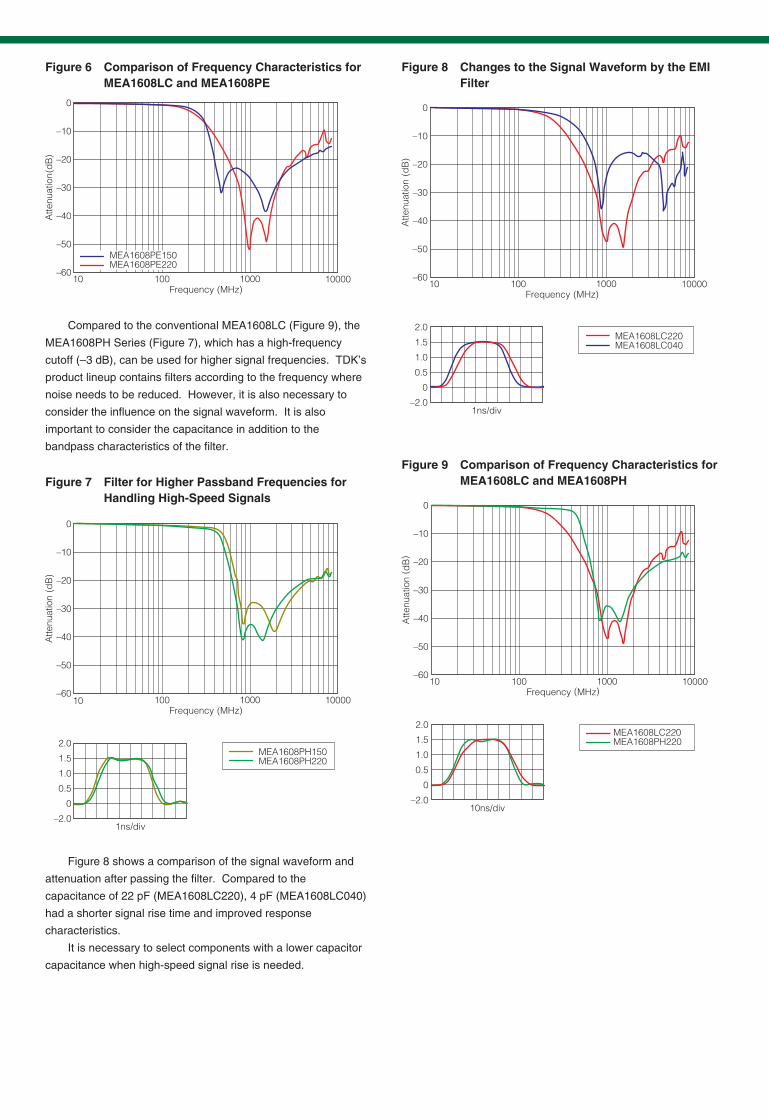
Compared to the conventional MEA1608LC (Figure 9), the
MEA1608PH Series (Figure 7), which has a high-frequency
cutoff (–3 dB), can be used for higher signal frequencies. TDK’s
product lineup contains filters according to the frequency where
noise needs to be reduced. However, it is also necessary to
consider the influence on the signal waveform. It is also
important to consider the capacitance in addition to the
bandpass characteristics of the filter.
Figure 8 shows a comparison of the signal waveform and
attenuation after passing the filter. Compared to the
capacitance of 22 pF (MEA1608LC220), 4 pF (MEA1608LC040)
had a shorter signal rise time and improved response
characteristics.
It is necessary to select components with a lower capacitor
capacitance when high-speed signal rise is needed.
Figure 7 Filter for Higher Passband Frequencies for Handling High-Speed Signals
Figure 6 Comparison of Frequency Characteristics for MEA1608LC and MEA1608PE
Figure 8 Changes to the Signal Waveform by the EMI Filter
Figure 9 Comparison of Frequency Characteristics for MEA1608LC and MEA1608PH
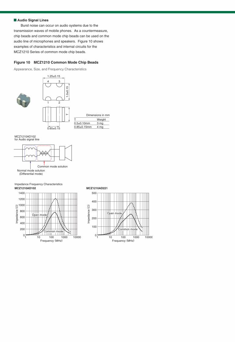
Audio Signal Lines
Burst noise can occur on audio systems due to the
transmission waves of mobile phones. As a countermeasure,
chip beads and common mode chip beads can be used on the
audio line of microphones and speakers. Figure 10 shows
examples of characteristics and internal circuits for the
MCZ1210 Series of common mode chip beads.
Figure 10 MCZ1210 Common Mode Chip Beads
Appearance, Size, and Frequency Characteristics