Embed Size (px)
Citation preview
)
RULES FOR CLASSIFICATION OF
MOBILE OFFSHORE UNITS
JULY 1988
INTRODUCTION Section 1 Instructions to Users ........................................................................................................ Page Section 2 Systematic Index .................................................................................................... , ......... Page 5 Section 3 Amendments and Corrections ........................................................................................ Page 12
RULES PART! REGULATIONS
Chapter 1 General Regulations January 1988 Chapter 2 Periodical Survey Regulations July 1988
PART2 MATERIALS AND WELDING
Chapter 1 Steel and Iron January 1985 Chapter 2 Aluminium, Copper and other Non-Ferrous Alloys September 1982 Chapter 3 Welding January 1984
PART3 STRUCTURES AND EQUIPMENT - MAIN CLASS
Chapter 1 Structural Design, General January 1988 Chapter 2 Special Designs, Equipment and Stability July 1988
PART4 MACHINERY AND SYSTEMS - MAIN CLASS
Chapter 1 Machinery and Systems Design, General February 1986 Chapter 2 Propulsion and Auxiliary Machinery September J 982 Chapter 3 Boilers, Pressure Vessels, Thermal-Oil Installations and Incinerators September 1982 Chapter4 Electrical Installations February 1986 Chapter 5 Instrumentation and Automation January 1985
PARTS SPECIAL SERVICE AND TYPE - ADDITIONAL CLASS
Chapter 1 Units for Transit and/ or Operation in Ice July 1985 Chapter 2 Accommodation Vessels and other Offshore Support Vessels September t982 Chapter 3 Drilling Vessels and other Vessels for Offshore Operations February 1986 Chapter 4 Oil Production and Storage Units foly 1987
PART6 SPECIAL EQUIPMENT AND SYSTEMS - ADDITIONAL CLASS
Chapter 1 Miscellaneous Notations January 1988 Chapter 2 Position Mooring (POSMOOR) January 1984 Chapter 3 Periodically Unattended Machinery Space (EO) September 1982 Chapter4 Additional Fire Protection (F-AM) January 1985 Chapter 5 Drilling Plant (DRILL) July 1988 Chapter 6 Oil Production Plant (PROD) July 1987
DETNORSKE VERITAS VERITASVEIEN 1, 1322 H0VIK, NORWAY
TELEPHONES: +47 2 47 99 00 TELEX: 76192
Det norskeVeritas (The Norwegian Veritas) is an independent Foundation with the object of safeguard-ing life and Property at ·sea and ashore. _ _:- · · . · .
The Foundation undertakes Classification and certification and secures the qtiality-of ships, facilities and systems, and ca_rries out research in connection with these fun~tions. Moreover, the· Fqundation·, pro~ided its· integritY--is not inip~ired, rriay_ perfofm assignments which utilize- its knowledge or which contribute to develop knowledge that will be required for the performance of these assignments. ·
The Foundation was established in 1978 as a direct continuation of the associ3;tio.n Det: qo_rske·veritas which wa! established in 1864.
CHANGES IN THE RULES The following Rule Chapters have been updated as of lst .. ofJuly 1988:
Pt. I Ch. 2 Pt. 3 Ch. 2 Pt. 6 Ch. 5
Periodical SurVey Regulations. Special Designs, Equipment and Stability. Drilling Plant (DRILL).
The-fcHlowing Rule Chapters have been subje·ct to sriialler amendments an~ corrections inseq.ed in the Ii.st of amendments and corrections: ·
Pt. 2 Ch. 3 Welding. Pt. 3 Ch. 1 Structural Design, General. Pt. 4 Ch. I Machinery and Systems Design, General.
The amendments come into force on 1st of July 1988.
© Det norske Veritas 1988 Printed in Norway by Det norske Veritas
7.88.2000
I
)
Mobile Offshore Units, Introduction
SECTION 1 INSTRUCTIONS TO USERS
A. Introduction. A l 00 General.
Rules. Format.
Contents.
B. The B 100 B 200 B 300 B 400 B 500 B 600 B 700 B 800
Numbering and cross references. Definitions. Units. Indexes and tables of contents. Amendments. Reprints from the Rules. Binders.
C. Guidelines and Notes. C l 00 General. C 200 Guidelines .. C 300 Classification Notes. C 400 Certification Notes. C · 500 Lists of Approved Manufacturers and Type
proved Products.
D. Computer Programs. D l 00 General. D 200 HULDA. D 300 PILOT. D 400 SESAM-80.
A. Introduction.
A 100 General.
Ap-
101 This booklet gives brief instructions to the users and include master indexes' as well as a list of corrections to the Rules. 102 Format and editorial details of the Rules are described in the following to facilitate easy use of the present edition of the Rules.
103 Guidelines and notes as defined and listed in C have been worked out to aid the users of the Rules. Guidelines and Classification Notes are published as a companion volume to the Rules, while Certification Notes and Lists of Approved Manufacturers as well as Lists of Type Approved Products are obtained separately upon request.
104 Computers play an ever increasing part in the evaluation of technical feasibility, determination of scantlings and plan approval. A summary of the HULDA, PILOT, and SESAM-80 computer systems has been included to inform users looking for computer power.
B. The Rules.
B 100 Format.
101 The Rules for Classification of Mobile Offshore Units are published as a ring binder with six parts (Pt.), each consisting· of chapters (Ch.) or booklets. The six parts are:
Pt. l Regulations Pt. 2 Materials Pt. 3 Structures and Equipment - Main Class Pt. 4 Machinery and Systems - Main Class Pt. 5 Special Service and Type - Additional Class Pt. 6 Special Equipment and Systems - Additional
Class.
A list of updated Rule Chapters is printed on the front of the introduction booklet.
102 Relevant requirements in Pt. l to 4 are to be satisfied for the assignment of main class. The requirements stated in Pt. 5 to 6 are applicable to additional class and are in general complete for the relevant notation. This implies that requirements regarding e.g. electrical installations may be found in Pt. 4, 5 or 6 depending on the class notation in question.
103 The introduction booklet giving current status of t.he Rules in the form of dates relevant to each chapter will be issued with each set of amendments. It is important that the users check that the date on the front page of the relevant Rule Chapter corresponds with that given in the list printed on the front page of the latest introduction booklet. Amendments to the Rules will normally be published twice yearly, in January and in July.
104 The front page of each chapter or booklet has a standard format which should be self explanatory.
105 The changes introduced in the latest edition of each Chapter will be stated on the page immediately after the front page.
106 The first section in each chapter will normally be termed General Requirements and will contain subsections covering such aspects as application of the Rules, definitions of symbols and terms, list of documentation etc.
107 Each subsequent section in the chapter will begin at the top of the page and will commence with a table of contents for the section.
B 200 Numbering and cross references.
201 A combi.nation of digits and letters is used for easy reference. It is felt that this combination provides better visibility with regard to levels, and -is easier to handle than a five digit string, e.g. Pt. 3 Ch. l Sec. l A l 00.
Level Ref. example Principle
Part Pt. 3 Chapter Ch. I always a number Section Sec. l
Subsection A always a letter
Item 100 always a number
202 Figures are numbered in increasing order within each section, e.g. Fig. l, Fig. 2 etc. The figure number and title are centered immediately under the figure.
203 Tables are numbered in increasing order within each sub-section, e.g. Table Al, Table A2 etc. The table number and title are placed above the top left hand corner of the table.
204 Each chapter is written as self contained as possible. Cross references are generally given at the highest level consistent with feasibility to find the subject matter:
(a) from part to part, e.g. see Pt. 2 Ch. l (i.e. down to chapter).
(b) from chapter to chapter within the same part, e.g. see Ch. l Sec. 3 (i.e. down to section). Reference to sub-section, e.g. Ch. l Sec. 3 A may be used where necessary for clarity.
(c) within a chapter, e.g. section to section, see Sec. 4 A l 00 (i.e. down to item) e.g. within a section, seeA !03 e.g. within a sub-section, see l 03.
M.obile Offshore Units, Introduction
B 300 Definitions.
301 Symbols and terms are in general defined at a·ne of three levels in the Rules. A definition given at higher level is normally not repeated at a lower level, and refe'. rences are not made to the definitions at higher level. When a symbol or term is defined elsewhere than in either of the· three general levels, -proper reference is made.
302 The first (higher) level of definitions is given in a separate subsection in Sec. 1 of the chapter in which the symbol or term is used. This level defines symbols and terms which are generally applied inthe chapter or booklet: .
303 The second (intermediate)level of definitions is given in subsection A of the section in which the symbol or term is used. This level normally defines symbols and terms occurring in ·various connections within the ·sec-
. tion.
304 The _third (lower) level of definitions is given in connectio-n :with the _formula or expression. in which the symb_ol .or ter·m. is used. The definiti9n is_ n_orrµaJly. given iminediately _ f~_llowing th_e form_ula and in ,-any _case within the same item as the formula.
B 400 Units.
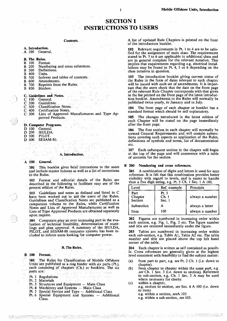
401 The units generally used in the Rules are the SIunits (International System of Units). Commonly used base and multiple units are given in Table· Al. Some derived units and-their conversion relation to the· TS-units (Technical Metric . .Sy~tem of Units) are given in -Tables A2 and A3, respectively. When other units are used _these are particularly stated.
Table Al Base or multiple SI-units.
Quantity Symbol .. Ncime
Length m metre cm centimetre mm millime·tre
Mass . kg . kilogram t tonne
Time s second
Electri_c current A ampere
Table A2 Derived SI-units.
Quantity Symbol .N·ame/ definition
Frequency· Hz • hertz~ l/s
Force_·_ N newton= kg· m/s2
kN kilonewton
Pressure- kN/m 2 ~ kPa, kilopascal bar ~.I 05 Pa
Stress N!m_m2 ~MPa, mega pascal
Bending moment N-m ~J, joule Torsional rnomen~ kN·m
Work, energy J joule~ N ·m
Heat kJ kilojo.ule
Power .kW kilowatt
Heat flow rate w watt
Tempef<ltl!re 'C centigrade
B 500 lode~ and tables of contents.
501 A master index has been prepared for the complete Rules in the form _of a systematic index. This index is presented in Sec. 2.
2
.
Table A3 SI/TS Convertion relation.
SI-unit TS-convertion relation
IN 0,1020 kp
I kN/m2 0,0102 kp/cm 2
IN/mm' I 0,20 kp/ cm'
I N·m 0,1020 kp·m
I J 0,1020 kp·m
I kJ 0,2388 kcal
lkW 1,36 Hp
IW 0,860 kcal/h
The systematic index gives reference to sections and subsections within each part/chapter. The master index will be updated as required when chapters are amended.
502 Two levels of table of contents are given at the beginning of each chapter. A table of sections only is given on the front page of the chapter, providing the starting page number for each section within the chapter. A complete table of sections, subsections and main items is also included giving page number references. _a~ subsection level.
503 A table of subsections and- main items is also included at the beginning of each .section. In these tables page numbering is not given.
B 600 Amendments.
601 Technical amendments to the Rules are the· results of formal proposals from the technical staff at the Society and are base<;I on practical experience from units in service as well aS comprehensive theoretical studies, research and development. TheSe proposals are always discussed with regional technical committees consisting of representatives of platformbuilders; -·marine engine builders, _ steel manufacturers, owners, oil- companies, maritim_e governmental, bo_dies,_ ins:ur_ance company_ associations and technical universities before._ being submitted to the Board for a decision.
602 Amendments to the Rules may be undertaken at any time, but wilI normally be publisheq twice a year, in January and July, and will be forwarded to subscribers
· of the Rules as revised chapters together with an updated index card.
603 The superseded index card and chapters may be filed in a separate binder for future. reference .
B 700 Reprints from the Rules.
701 Reprints from the Rules are available from the Society on request. -There is currently· no subscription scheme for reprints. While the Society will publish details qf amendments -to the Rules in the press and in its own magazines, no special notification of amendments to buyers of reprints will be undertaken.
B 800 Binders.
801 The mechanism in the binder provides for two stages of opening. The half open position is ·recommended for general reading and. use of the Rules. The full open position should only be used for ins.ertion of new chapters or removal of old chapters. Every effort has been made to deliver a high quality binder. Defective binders may be returned to the Society for a free replacement. Additional binders for working files, historical files, etc., may be supplied at a nominal charge.
)
. )
C. Guidelines and Notes.
C 100 General.
101 In an effort to aid the various parties involved in the classification· of ships or mobile offshore units, VERIT AS has issued Guidelines and Classification Notes giving practical information regarding classification and other relevant regulations as well as guidance in new fields of technology. These publications are available as a complementary volume to the Rules, on a purchase or subscription basis, and contains Guidelines and Classification Notes as specified in 200 and 300. Each of the Guidelines and Classification Notes may also be purchased individually.
102 Products which are to be approved for installation onboard a vessel or other object classed.with the Society may be granted type. approval. VERIT AS has issued Lists of Approved Manufacturers and Type Approved Products containing the names of manufacturers and types of products which have been granted approval. The approval is tiJ11e limited and updated lists are normally published anually.
C 200 Guidelines.
201 Guidelines are publications which give information and advice on technical and formal matters related to the design, building, operating, maintenance and repair of vessels and other objects, as well as the services rendered by the Society in this connection. Aspects concerning classification may be included in the publication.
202 The following Guidelines have been prepared:
Design and Classification of Roll on/Roll off Ships, May 1980. Prevention of Harmful Vibration in Ships, July 1983. Internal Control, Mobile Offshore Units (Owners' Control System), September 1983. Stability Information for Mobile Offshore Units. Class and Statutory Services, November 1986. Documentation Required for SC Class, June 1988.
C 300 Classification Notes.
301 - Classification Notes are publications which give practical information on classification of ships and other objects. Examples of design solutions, calculation methods, specifications of test procedures,: as well as acceptable repair methods for some components are given as interpretations of the more general rule requirements.
302 The following Classification Notes have been prepared:
No. 4.1 Guidance Manual for Inspection and Repair of Bronze Propellers, May 1980. (Reprint of 1974).
No. 4.2 Guidance Manual for Inspection and Repair of Steel Propellers, May 1980. (Reprint of August 1977).
No. 6. Fire Test of Components Intended for Use in Piping Systems on Board Ships, May 1980. (Reprint of 1975).
No. 6.1 Fire Test Methods for Plastic Pipes, Joints and Fittings, January 1987.
No. 7. Ultrasonic Inspection of Weld Connections, May 1980. (Reprint of November 1978).
No. 10.l Ships and Mobile Offshore Units, Planned Maintenance Systems as Basis for Survey for Retention of Class, May 1983.
No. 13. Erosion and·Corrosion in Piping Systems for Sea Water, May 1980. (Reprint of January 1979).
No. 14. Instrumentation and Automation, Computer Based Systems, July 1984.
No. 30.1 Buckling Strength Analysis of Mobile Offshore Units, October 1987.
No. 30.2 Fatigue Strength Analysis for Mobile Offshore Units, August 1984.
3 Mobile Offshore Units, Introduction
No. 30.3 Spherical Shells Subjected to Compressive Stresses, October 1987.
No. 31.l Strength Analysis of Hull Structures in Bulk Carriers and Container Ships, May 1980 ..
No. 31.2 Strength Analysis of Hull Structures in Roll · on/Roll off Ships, May 1980.
No. 31.3 Strength Analysis of Hull Structures in Tankers, May 1980.
No. 31.4 Strength Analysis of Main Structures of Column Stabilized Units (Semisubmersible Platforms), September 1987.
No. 31.5 Strength Analysis of Main Structures of SelfElevating Units, May 1984.
No. 32. l Strength Analysis of Rudder Arrangements, January 1984.
No. 32.2 Strength Analysis of Container Securing Arrangements, July 1983.
No. 41.1 Reduction Gears in Lifting Machinery for SelfElevating Units, September 1982.
C 400 Certification Notes.
401 Certification Notes are publications which contain principles, accept criteria and practical information related to the Society's consideration of objects, personnel, organizations, services and operations, in connection with issuance of certificates or declarations, which are not necessarily related to classification.
402 The following Certification Notes have been prepared or are.under preparation:
Series No. 1 Quality System Certification. No. I.I Basic Service Description (June 1985). No. 1.3 Quality Assurance Requirements for the Manu
facturing Phase (June 1985).
Series No. 2 Approval Schemes. No. 2.2 Certification Scheme Based on Type Approval
(January 1982). No. 2.4 Type Approval of Instrumentation and Auto
mation Equipment (March 1988). No. 2.5 Type Approval of Loading Instrument for
Ships (June 1985). No. 2.6 Certification of Offshore Mooring Chain (July
1985).
Series No. 3 Marine Operations. No. 3.3 Declarations on Lay-up of Ships (August 1983). No. 3.4 Declarations on Preservation of Laid-up Ships
(August 1976).
C 500 Lists of Approved Manufacturers and Type Appro-ved Products.
501 Lists of approve.d Manufacturers. The following lists have been issued:
100 Companies with Veritas Certified Quality Systems. 101 Metallic Materials. 102 Welding.
502 List of Type Approved Products. The following lists have been issued:
1 Non-Metallic Materials. 2 Not in use. 3 Structural Equipment, Containers, Cargo Handling
and Securing Equipment. 4 Machinery Components. 5 Mechanical Equipment and Piping. 6 Electrical Equipment and Systems. 7 Instrumentation and Automation. 8 Fire Restricting Materials and Fire Technical Equip
ment. 9 Drilling and Well Control Equipment.
503 The lists are normally updated annually.
Mobile Offshore Units, Introduction
D. Computer Programs.
D 100 General.
101 Computers play an increasingly important role in both .evaluation of technical feasibility, determination of scantlings by direct calculation and as ·a means of speeding up the approval process.
D 200 HULDA.
201 Plan approval has traditionally been supported by the HULDA hull analysis and design package. The system is designed for the UNIV AC ll 00 series computers and comprises a suite of independent programs which may be run separately, or as part of an integrated system. The basis modules are:
• Hull definition forms • Wave load and ship motion • Longitudinal strength • Hull section programs • Frame and grillage analysis programs.
202 The longitudinal strength and hull section programs in HULDA can be replaced by corresponding programs in the PILOT system de.scribed below.
D 300 PILOT.
301 As an alternative for users who do not have access to a large computer, or who might wish to implement decentralized computation, VERIT AS offers a desk top computer system based on the Hewlett Packard 9845 and Series 200 desk top computers. The system is named PILOT and contains interactive programs covering:
• Preliminary ship design, i.e.: generation of lines, hydrostatics and propulsion data from model series and steel weights related to bulk carriers and tankers.
• Hull geometfy calculations and statutory requirements, i.e.: hull definition, hydrostatics, stability and plot of hydrostatic and cross curves.
• General strength, i.e.: longitudinal hull strength, area properties of.arbitrary sections at structural members, buckling of plates and profiles.
• VERIT AS rule requirements related to hull section scantling analysis, deckhouses, decks for wheel loading, propeller blade thicknesses, gears, ~tc.
302 In most countries this system may be offered as a turn-key system including the computer, or may be obtained from our program library on a lease basis. This system is an important tool at selected VERIT AS locaiions in keeping-with our policy ·of providing a consistently high level of technical expertise and capability throughout the wor.ld.
4
D 400 SESAM.-80.
401 SESAM-80 is a general purpose finite element program system developed by VERIT AS. The system incorporates advances made during the last decade in structural and solid mechanics, numerical analysis and computer technology.
SESAM-80 is designed to handle static and dynamic analysis of:
• 2- and 3-dimensional truss/frame structures • 2- and 3-dimensional membrane structures • thin and thick shell structures • axi-symmetric solids • 3-dimensional solids
Geometrical as well as material nOn-linerarities may be taken into account. Particular emphasis is placed upon the development of efficient pre- and post-processors.
402 SESAM-80 includes integrated program packages for extensive analysis of:
• ships • mobile offshore units (column stabilized and self-
elevating) • tension leg platforms • fixed steel platforms
For these structures the analysis may include calculation of loads, response, capacity and checking against codes etc.
403 Several alternative methods are available. The multilevel superelement technique may be used for static as well as for dynamic analysis. A number of programs for calculation of different types of loading, e.g. wave loads and temperature distri~utions, are integrated in the SESAM-80 system. Fluid-structure and soil-structure may also be taken into account.
404 The development of non-linear programs is concentrated .into the FENRIS system. The theoretical basis for this system is broad, allowing for very large displacements and rotations, finite strains, almost any type of material non-linearity, static and dynamic behaviour etc. It is expected that the system will be well suited for solving a great variety of problems involving structural instabilities, collapse, residual strength, fatigue etc.
405 The SESAM-80 system is available from VERITEC A/S, a subsidiary of Det norske Veritas.
5 Mobile Offshore Units, Introduction
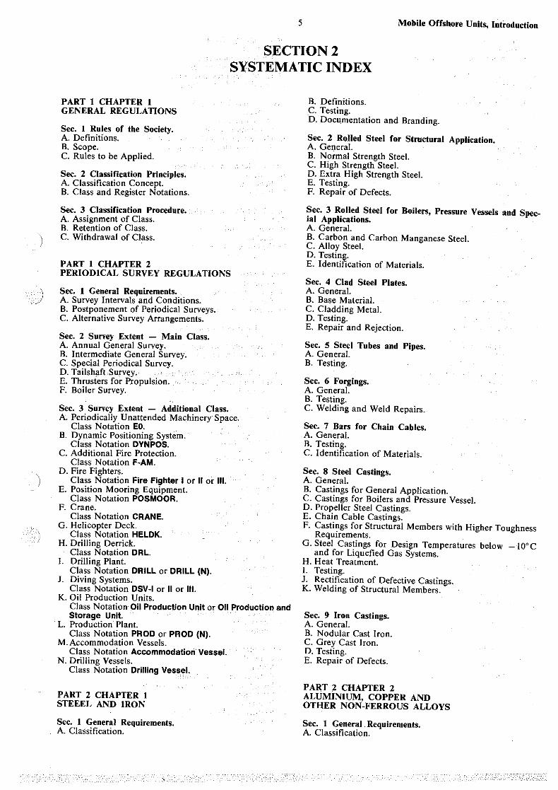
SECTION2 SYSTEMATIC INDEX
PART 1 CHAPTER 1 GENERAL REGULATIONS
Sec. 1 Rules of the Society. A. Definitions. B. Scope. C. Rules to be Applied.
Sec. 2 Classification Principles. A. Classification Concept. B. Class and Register Notations.
Sec. 3 Classification Procedure. A. Assignment of Class. B. Retention of Class. C. Withdrawal of Class.
PART 1 CHAPTER 2 PERIODICAL SURVEY REGULATIONS
Sec. 1 General Requirements. A. Survey Intervals and Conditions. B. Postponement of Periodical Surveys. C. Alternative Survey Arrangements.
Sec. 2 Survey Extent - Main Class. A. Annual General Survey. B. Intermediate General Survey. C. Special Periodical Survey. D. Tailshaft Survey. E. Thrusters for Propulsion. F. Boiler Survey.
Sec. 3 Survey Extent - Additional Class. A. Periodically Unattended Machinery Space.
Class Notation EO. B. Dynamic Positioning System.
Class Notation DVNPOS. C. Additional Fire Protection.
Class Notation F-AM. D. Fire Fighters.
Class Notation Fire Fighter I or II or Ill. E. Position Mooring Equipment.
Class Notation POSMOOR. F. Crane.
Class Notation CRANE. G. Helicopter Deck.
Class Notation HELDK. H. Drilling Derrick.
Class Notatio.n DRL. I. Drilling Plant.
Class Notation DRILL or DRILL (N). J. Diving Systems.
Class Notation DSV-1 or II or Ill. K. Oil Production Units.
Class Notation Oil Production Unit or Oil Production and Storage Unit.
L. Production Plant. Class Notation PROD or PROD (N).
M. Accommodation Vessels. Class Notation Accommodation Vessel.
N. Drilling Vessels. Class Notation Drilling Vessel.
PART 2 CHAPTER I STEEEL AND IRON
Sec. 1 General Requirements. A. Classification.
B. Definitions. C. Testing. ·o. Docu_mentation and Branding.
Sec. 2 Rolled Steel for Structural Application. A. General. B. Normal Strength Steel. C. High Strength Steel. D. Extra High Strength Steel. E. Testing. F. Repair of Defects.
Sec. 3 Rolled Steel for Boilers, Pressure Vessels and Special Applications. A. General. B. Carbon and Carbon Manganese Steel. C. Alloy Steel. D. Testing. E. Identification of Materials.
Sec. 4 Clad Steel Plates. A. General. B. Base Material. C. Cladding Metal. D. Testing. E. Repair and Rejection.
Sec. 5 Steel Tubes and Pipes. A. General. B. Testing.
Sec. 6 Forgings. A. General. B. Testing. C. Welding and Weld Repairs.
Sec. 7 Bars for Chain Cables. A. General. B. Testing. C. Identification of Materials.
Sec. 8 Steel Castings. A. General. B. Castings for General Application. C. Castings for Boilers and Pressure Vessel. D. Propeller Steel Castings. E. Chain Cable Castings. F. Castings for Structural Members with Higher Toughness
Requirements. G. Steel Castings for Design Temperatures below -10°C
and for Liquefied Gas Systems. H. Heat Treatment. I. Testing. J. Rectification of Defective Castings. K. Welding of Structural Members.
Sec. 9 Iron Castings. A. General. B. Nodular Cast Iron. C. Grey Cast Iron. D. Testing. E. Repair of Defects.
PART 2 CHAPTER 2 ALUMINIUM, COPPER AND OTHER NON-FERROUS ALLOYS
Sec. 1 General . Requirements. A. Classification.
Mobil~ Offshore Unjts,Introduction
B. Definitions. C. Testing. D. Documentation and Branding.
Sec. 2 Wrought Aluminium Alloys. A. General. B. Testing. C. Repair of Defects. D. Identification of Materials.
Sec. 3 Copper Alloys. A. General. B. Castings for Valves and Fittings. C. Propeller Castings. D. Tubes.
Sec. 4 Heat Resisting Non-Ferrous Alloys. A. General. B. Testing.
PART 2 CHAPTER 3 WELDING
Sec. 1 General Requirements. A. General. B. Definitions. C. Testing.
Sec. 2 Welding Procedures and Approval of Welders. A. General. B. Welding Procedures. C. Approval of Welders.
Sec. 3 Welding ConsumabJes. A. General. B. Electrodes for Manual, Metal-Arc Welding. C. Wire Flux Combinations for Submerged Arc Welding. D. Combinations for Use in One-side Automatic Welding
Processes. E~ Wire-Gas Combinations and Wires for Automatic and
Semi-Automatic Welding. F. Combinations for Use in Electro-Slag and Electro-Gas
Welding Processes. G. Welding Consumables for Welding of Steel Grades NV
2-4 and NV 4-4 for Low-temperature Applications. H. Welding Consumables for Low-Alloy, Heat Resisting
Steels (NV 7-1,7-2 and 7-3). I. Welding Consumables for Welding of Steel Grades NV
20-00, NV 20-0, NV 20-1 and NV 20-2. ' J. Welding Consumables for. Welding of Normal.ized or
Quenched and Tempered Structural Sieels with Specified Yield Stress 420 N/mm2 and Higher.
Sec. 4. Welding of Clad Steel Plates. A. General. B. Welding.
PART 3 CHAPTER I STRUCTURAL DESIGN GENERAL
Sec. 1 General Requirements. A. Classification. B. Definitions. C. Documentation. D. Appendix to the Classification Certificate.
Sec. 2 Materials. A. General. B. Structural Steel. C. Alternative Structural Materials.
Sec. 3 Design Principles. A. General. B. Environmental Conditions. C. Strength Analysis. D. Deflections and Vibrations.
6
Sec. 4 Design Loads. A. General. B. Environmental Data. C. Flo'w Induced Forces. D. Local Pressures and Forces. E. Accidental Impact Energy.
Sec. 5 Overall Strength. A. General B. Design Load Conditions. C. Calculation Methods. D. Usage Factors and Permissible Stresses. E. Structures Other than Steel.
Sec. 6 Plating and Stiffeners. A. General. B. Bending. C. Buckling.
Sec. 7 Girders and Girder Systems. A. General. B. Bending and Shear. C. Buckling. D. Complex Girder Systems. E. Girder Brackets.
Sec. 8 Weld Connections. A. General. B. Types of Welded Steel Joints. C. Size of Connections ... D. Welding of Aluminium Structures.
Sec. 9 Corrosion Protection. A. General. B. Acceptable Corrosion Protection. C. Cathodic Protection.
Sec. 10 Manufacture, Workmanship and Testing. A. Manufacturing Conditions and Workmanship. B. Testing during Construction.
PART 3 CHAPTER 2 SPECIAL DESIGNS, EQUIPMENT AND STABILITY
Sec. 1 General Requirements. A. Classification. B. Definitions. C. Documentation.
Sec. 2 Column Stabilized Units .. A. General. B. Air Gap. C. Design Load. D. Overall Strength. E. Local Strength. F. Resistance Against Collosion, Dropped Objects, Fire and
Explosions.
Sec. 3 Self-elevating Units. A. General. B. Air Gap. C. Design Load. D. Overall Strength. E. Local Strength. F. Overturning Stability on the Sea Bed. G. Resistance Against Collosion, Dropped Objects, Fire and
Explosions.
Sec. 4 Steering Arrangements. A. General B. Materials. C. Arrangement and Details. D. Design Loads and Stress Analysis. E. Sternframes. F. Rudders. G. Rudder Stocks and Pintles. H. Steering Gears. I. Testing.
)
Sec. 5 Mooring and Towing Equipment. A. General. B. Structural Arrangement for Mooring Equipment. C. Equipment Specification. D. Anchors. E. Anchor Chain Cables. F. Steel Wire Ropes. G. Windlass and Chain Stopper. H. Fairleads. I. Wire End Attachments. J. Arrangement and Devices for Towing:
Sec. 6 Stability. A. General. B. Inclining Test. C. Loading Conditions. D. Stability Calculations. E. Intact Stability. F. Damage Stability.
Sec. 7 Watertight Integrity, Freeboard and Watertight Closing Appliances. A. Watertight Integrity. B. Freeboard. C. Weathertight Closing Appliances.
PART 4 CHAPTER I MACHINERY AND SYSTEMS DESIGN, GENERAL
Sec. 1 General Requirements. A. C1assification. B. Defiiiitions. C. Documentation. D. Signboards.
Sec. 2 Materials. A. General. B. Machinery Parts. C. Piping Systems.
Sec. 3 Design Principles. A. Arran_gement. B. Construction and Function. C. Reliability and Availability. D. Instrumentation and Automation.
Sec. 4 Platform Piping Systems. A. General. B. Ballast, Bilge and Drainage Systems General. C. Ballast and Bilge Systems for Column Stabilized Units. D. Ballast and Bilge System for Se!felevating Units. E. Air, Overflow and Sounding Pipes. F. Storage and Transfer Systems for Liquids with Flash-
point below 60°C (e.g. Helicopter Fuel).
Sec. 5 Machinery Piping Systems. A. General. B. Cooling Systems. C. Lubricating Oil Systems. D. Fuel Oil Systems. E. Feed Water and Condensate Systems. F. Steam Systems. G. Hydraulic Power Supply. H. Pneumatic Power Supply. I. Pneumatic Starting Arrangements.
Sec. 6 Pipes, Pumps, Valves, Flexible Hoses and Detachable Pipe Connections etc. A. Pipes. B. Pumps. C. Valves. D. Flexible Hoses. E. Detachable Pipe Connections. F. Seawater Strainers. G. Socket Welded Joints.
7 Mobile Offshore UnitS, IDtrod-uction
Sec. 7 Fire Safety. A. General. B. Fire Integrity and Fire Protection. C. Fire Extinguishing Systems. D. Fire Detection System. E. ·Firemen's Outfits and Breathing Apparatus. F. Arrangements in Machinery and Working Spaces. G. Provisions for Helicopter Facilities. H. Storage of Gas Cylinders. I. Miscellaneous.
Sec. 8 Manufacture, Workmanship and Testing. A. Welding. · B. Brazing of Copper and Copper Alloys. C. Pipe Bending. D. Hydrostatic Tests of Piping. E. Functional Testing.
Sec. 9 Spare Parts. A. General.
PART 4 CHAPTER 2 PROPULSION AND AUXILIARY MACHINERY
Sec. 1 General Requirements A. Classification. B. Definitions and Design Criteria. C. Documentation. D. Signboards.
Sec. 2 Diesel Engines A. General. B. Materials. C. Arrangement. D. Design and Construction. E. Governing and Monitoring. F. Testing.
Sec. 3 Reduction Gears A. General. B. Materials. C. Arrangement. D. Design and Construction. E. Monitoring. F. Testing.
Appendix: Gear Calculation Factors A. General. B. Geometrical definitions. C. Load-increasing factors. D. Factors for actual tooth root stresses. E. Material fatigue value$. F. Safety factors. G. Relative stress correction factor. H. Relative influence of the notch sensitivity on the fatigu(;
strength. I. Zone factor. J. Lubrication factor. K. Influence of the depth of the surface hardened layer on
the fatigue strength.
Sec. 4 Shafting A. General B. Materials. C. Arrangement and Dynamics. D. Design and Scantlings. E. Testing.
Sec. 5 Propellers A. General. B. Materials. C. Arrangement. D. Design and Scantlings. E. Governing and Monitoring. F. Testing.
Mobile Offshore Units, Introduction
Sec. 6 Thrusters A. General. B. Materials. C. Arrangement. D. Design and Construction. E. Control and Monitoring. F. Testing.
Sec. 7 Jacking Machinery A. General. B. Materials. C. Arrangement and Ge11eral Design. D. Scantlings. E. Control and Monitoring. F. Testing.
PART 4 CHAPTER 3 BOILERS, PRESSURE VESSELS, THERMAL-OIL INSTALLATIONS AND INCINERATORS
Sec. 1 General Requirements. A. Classification. B. Definitions. C. bocumentation. D. C02 Bottles. E. Signboards.
Sec. 2 Materials. A. General. B. Boilers and Pressure Vessels. C. Thermal-Oil Installations.
Sec. 3 Arrangement. A. Boilers and Pressure Vessels. B. Thermal-Oil· Installations. C. Incinerators.
Sec. 4 Basic Design Requirements. A. General. B. Design Criteria. . C. Scantlings of Shells and Flat and Dished Ends. D. Cpenings and Compensations. E. Covers for Inspection Openings and Manholes.
Sec. 5 Particular Design Requirements for Boilers. A. Shells and Headers of Cylindrical Sections. B. Headers of Rectangular .or Irregular Sections. C. Flat Plates Supported by Stays, Combustion Chambers
Excepted. · D. Furnaces, Uptakes and Cross Tubes Subjected to Ex-
ternal Pressure. E. Combustion Chambers in Horizontal Cylindrical Boilers. F. Tube Plates in Vertical Boilers. G. Stay Bolts, Longitudinal Stays and Stay Tubes. H. Tubes.
Sec. 6 Mountings and Fittings. A. General. B. Safety Valves. C. Stop Valves and Check Valves. D. Blow Down Valves and Test Valves for Boiler Water. E. Gauges.
Sec. 7 Instrumentation and Automation. A. General. B. Boilers. C. Water Heaters. D. Thermal-oil Heaters. E. Incinerators.
Sec. 8 Manufacture, Workmanship and Testing. A. Manufacture. B. Workmanship. C. Heat treatment. D. Testing.
8
PART 4 CHAPTER 4 ELECTRICAL INSTALLATIONS
Sec. 1 General Requirements. A. Classification. B. Definitions. C. Documentation. D. Signboards.
Sec. 2 Design Principles. A. Environmental Conditions. B. Explosion-Prote.cted Equipment. C. Enclosures. D. Earthing of Non-Current-Carrying Parts. E. Electromagnetic Noise and Interference. F. Insulating Materials. G. Marking.
Sec. 3 System Design. . A. Supply Systems. Maximum _V~ltages.
·Voltage and Frequency Variations. B. Capacity and Arrangement of Generators and Power
Convertors. . C. Emergency Source of Power an_d Emergency Installatton. D. Stationary Accumulator Batteries. . ..
Electric Starting Arrangements for Main and Auxiliary Engines. Charging stations for Battery Trucks.
E. Distribution. F. Circuit Protection. G. Control Gear for Motors and other Consumers. H. Choice of Cable Types.
Sec. 4 Switchgear and Control Gear Assemblies. A. Main and Emergency Switchboards. B. Distribution Switchboards. C. Enclosures for Motor Control Gear. D. Testing and Certification.
Sec. 5 Rotating Machines. A. Requirements Common to Generators and Motors. B. Additional Requirements to Generators.
Sec. 6 Static Convertors. A. Transformers. B. Static Convertors with Semicond~ctors.
Sec. 7 Cables. A. Construction. B. Testing.
Sec. 8 Miscellaneous Equipment. A. Switchgear. Control gear. B. Fuse-gear. C. Socket-outlets. D. Lampholders. E. Lighting Fittings. F. Heating Equipment. G. Marking.
Sec. 9 Installation and Testing. A. General. B. Essential or Important Equipment. C. Cables. D. Testing.
Sec. 10 A.C. Supply Systems above 1 kV to and including 11 kV. A_. General Requirements. B. Design Principles. C. System Design. . D. Switchgear and Controlgear Assembhes. E. Rotating Machines. F. Static Convertors. G. Cables, Construction and Testing. H. Miscellaneous Equipment. I. Installation and Testing.
•• •• -,--,-•• vc•,•• ''.·",;'~"-~~·::-;v-.~,"C-~::::_~ .-_,,_ ... ";
PART 4 CHAPTER 5 INSTRUMENTATION AND AUTOMATION
Sec. 1 General Requirements · A. Classification. B. -Definitions. C. Testing of Plant on Board.
Sec. 2 System Design. A. General. B. Automatic Control Systems. C. Alarm Systems. D. Safety Systems. E. Indicating and Recording Systems. F. Remote Control Systems. G. Sequence Control Systems. H. Indication and Transfer of Responsibility. I. Computer Based Systems. J. Monitoring for Electric Propulsion Machinery.
Sec. 3 Component Design and Installation. A. General. . B. Environmental Conditions. C. Electrical and Electronic Equipment. D. Pneumatic and Hydraulic Equipment.
PART 5 CHAPTER 1 UNITS FOR TRANSFER AND/OR OPERATION IN ICE
Sec. 1 Units for Occasional Transit _and/or Operation in First Year Ice Conditions. A. Classification. B. Definitions. C. Documentation. D. Ice Strengthening.
PART 5 CHAPTER 2 ACCOMMODATION VESSELS AND OTHER OFFSHORE SUPPORT VESSELS
Sec. 1 General Requirements. A. Classification. B. Definitions. C. Documentation.
Sec. 2 Accommodation Vessels. A. General. B. Structural Arrangement and Strength. C. Mooring Equipment. D. Machinery and Systems. E. Stability and Floatability.
Sec. 3 Fire Fighters. A. General. B. Basic Requirements. C. Self-Protection of the Vessel.
(Class Notation I). D. Water Monitor System. E. Foam Monitor System.
(Class Notation Ill). F. Pumps and Piping. G. Mobile Fire Fighting Equipment. H. Fireman's Outfit.
Sec. 4 Crane Vessels. A. General. B. Structural Arrangement and Strength. C. Stability and Floatability. D. Testing.
9 Mobile Offshore Units, Introduction
PART 5 CHAPTER 3 DRILLING VESSELS AND OTHER VESSELS FOR OFFSHORE OPERATIONS
Sec. 1 General Requirements. A. Classification. B. Definitions. C. Documentation.
Sec. 2 Drilling Vessels. A. General. B. Structural Arrangement and Strength. C. Stability and Floatability. D. Mooring and Towing Equipment. E. Drilling Related Equipment and Systems. F. Pumping and Piping Arrangement. G. Protection against Fire and Explosion. H. Electrical Installations in Hazardous Areas. I. Machinery Installations in Hazardous Areas. J. Safety Features.
Sec. 3 Pipe Laying Vessels. A. General. B. Structural Arrangement and Strength. C. Mooring Equipment. D. Pipe Laying Equipment and Installation. E. Stability and Floatability.
Sec. 4 Dredgers. A. General. B. Structural Arrangement and Strength. C. Stability and Floatability.
PART 5 CHAPTER 4 OIL PRODUCTION AND STORAGE UNITS
Sec. 1 General Requirements. A. Classification. B. Definitions. C. Documentation. D. Accessibility and Facilities for Surveys on Location. E. Commissioning Testing.
Sec. 2 Oil Production Facilities and Arrangement of Unit. A. General. B. Basic Requirements.
Sec. 3 Structural Strength. A. General.
Sec. 4 Hazardous Areas and Ventilation. A. General. B. Basic Requirements.
Sec. 5 Machinery and Piping Arrangement. A. General. B. Combustion Equipment and Combustion Engines. C. Use of Gas and Crude Oil for Auxiliary Boilers and
Turbines. D. Piping Arrangement.
Sec. 6 Fire Protection and Extinction. A. General. B. Structural Fire Protection. C. Fire Control and Extinction. D. Fire and Gas Detection Systems.
Sec. 7 Electrical Installations. A. General. B. Basic Requirements ..
Sec. 8 Instrumentation and Control Systems. A. General. B. Basic Requirements.
Sec. 9 Materials. A. General.
M.obile .Offshore Units, Introduction
App. A: Supplementary Requirements of the Norwegian Petroleum Directorate. (NPD).
App. B: Supplementary Requirements of the Department of Ener~y (DEn).
PART 6 CHAPTER 1 MISCELLANEOUS NOTATIONS
Sec. 1 General Requirements. A. Classification. B. Definitions. C. Documentation.
Sec. 2 Helicopter Decks. A. General. B. Design Loads., C. Strength Requirements.
Sec. 3 Cranes. A. General. B. Design Loads. C. Overturning and Sliding. D. Testing.
Sec. 4 Diving Systems. A. General. B. Position Keeping. C. Arrangement. D. Electrical Systems. E. Sanitary Systems for Class JI and lit Diving Systems. G. Testing.
PART 6 CHAPTER 2 POSITION MOORING (POSMOOR)
Sec. 1 General Requirements. A. Classification. B. Documentation. C. Structural Arrangement for Mooring Equipment.
Sec. 2 Environmental Conditions and Loads. A. Environmental Conditions. B. Environmental Loads.
Sec. 3 Mooring System Analysis. A. Method. B. Design Conditions. C. Permissible Usage Factors. D. Use of Thrusters.
Sec. 4 Mooring Equipment. A. Anchors. B. Anchor Lines of Chain Cables/Steel Wife Ropes. C. Fairleads. D. Windlasses, Winches and Stoppers.
Sec. 5 Tests. A. Test of Windlass/Winch.
PART 6 CHAPTER 3 PERIODICALLY UNATTENDED MACHINERY SPACE (EO)
Sec. 1 General Requirements. A. Classification. B. Definitions. C. Documentation. D. Signboards.
Sec. 2 Systeni Arrangement. A. General. B. Automatic Control System. C. Alarm System.
IO
D. Safety System. E. Bridge Control of Propulsion Machinery. F. Communication System. G. Computer Based Systems.
Sec. 3 Extent of Monitoring and General Require.ments. A. Monitoring. B. Arrangement on the Bridge. C. Arrangement in the Engine Room. D. Electric Power Supply.
Sec. 4 Precautions .Against Fire. A. Shielding. B. Fire Detection. C. Fire Alarm System. D. Remote Control.
Sec. 5 Testing. A. General. B. Testing of Remote Control System. C. 'Blackout Test. D. Testing of Boiler Plant.
PART 6 CHAPTER 4 ADDITIONAL FIRE PROTECTION (F-AM)
Sec. 1 General Requirements. A.- Classification. B. Definitions. C. Documentation. D. Signboards.
Sec. 2 Accommodation. A. General. B. Fire Protection. C. Fire Extinguishing Systems. D. Fire Instruction.
Sec. 3 Machinery Spaces. A. General. B. Oil Systems. C. Ventilation. D. Fire Pumps. E. Main Extinguishing System. F. Halon Total Flooding Extinguishing System. G. High-Expansion Foam Extinguishing System. H. Local Extinguishing Systems. I. Hose Stations. J. Dry Powder Extinguishers. K. Fireman's Outfit.
PART 6 CHAPTER 5 DRILLING PLANT (DRILL)
Sec. 1 General. A. Application. B. Definitions. C. Recognized Codes. D. System Design Review. E. Equipment Certification. F. Documentation.
Sec, 2 Materials. A. General. B. Specific Requirements. C. Corrosion. D. Material Certificates.
Sec. 3 Design Principles. A. Principal Requirements.
Sec. 4 Systems. A. General. B. Blowout Prevention System. C. Marine Riser System.
D. Heave Compensation and Tensioning System. E. Hoisting, Rotating and Pipe Handling System .. F. Bulk Storage, Drilling Fluid Circulation and Cementing. G. Well Test and Flare System.
Sec. 5 Structural and Mechanical Components. A. General. . · B. Specific· Component Requireme.nts.
Sec. 6 Piping. A. General: B. Piping Design. C. Supporting Elements.
Sec. 7 .Manufactui:e, Work.man~hip and Testing. A. General. B. Manufacture. C. Non-destructive Examination (NOE). D. Testing.
App. A: Supplementary Requirements of the Norwegian Petroleum Directorate (NPD) and the No..Wegian Maritime Directorate (NMD ).
App. B: Supplementary Requirements of the U.K. Department of Energy (DEn).
PART 6 CHAPTER 6 OIL PRODUCTION PLANT (PROD)
Sec'· l General. A. Application. B. Definitions. C. ·Principal Reqp.irements.
Sec. 2 Production and Utility Systems. A, General. . B. Safety of Process an.d. Utility Systems. C. Relief, Depressurising and Disposal SyStems. D. Document&tion.
Sec. 3 Riser Systems; A. General. B. -Envitonment: C. Loads. D. Strength. E. Flexible Risers. F. Materials and Co'rtosion Protection. G. Manufacturing, Workmanship and Testing. H. Installation Surveys and Testing. L· -Tensio'ners. J. Riser Safety- and Control System. K. DocumentaJion.,
II Mobile Offshore Units, Introduction
Sec. 4 Equipment. A. General. B. Documentation. C. Design Requirements. D. Materials. E. Recognized Codes and Standards. F. Manufacture, Testing and Certification.
Sec. 5 Piping. A. General. · B. Documentation. C. Piping Arrangement. D. Piping Design. E. Design of Supporting Elements. F. Piping Material. G. Manufacture, Workmanship.and Testing.· H. Fabrication Documentation.
Set. 6 Structures~ A. GeneraL B. Basic Requirements. C. Design of Flare Structures. D. Design of Derrick Structures. E. Design of Skids. F. Documentation.
Sec. 7 Materials and Corrosion Protection. A. General. B. Rolled Steel. C. Clad Steel Plates. D. Steel Piping. E. Steel Forgings. F. Steel and Iron Castings. . G. Aluminium, Copper and other Non-ferrous Alloys. H. Bolts, Nuts, Sealing Materials and Polymers. I. Corrosion Protection.
Sec. 8 Electrical Installations. A. General.
Sec. 9 Instrumentation and Control Systems. A. General. B. System Design.
Sec. 10 Fire Protection and Extinction: A. General. B. Fire Control and .EX:tinction·. C. Fire and Gas Detection System.
Sec. 11 Manufacture, Workmanship and Testing. A. Principles. B. Categories of Equipment. C. Manufacture. D. Control and Testing during Fabrication.
App. A: Supplementary Requirements of the Norwegian Petroleum Directorate (NPD).
App. B: Supplementary Requirements of the Department of Energy (DEn).
. Mobile Offshore Units, Introduction 12
SECTION3 AMENDMENTS AND CORRECTIONS
Pt.2 Ch.3 Sec.2 Page 4
• Item B in Contents has been amended to read:
B. Welding Procedures. B 100 Welding procedure specifications, WPS. B 200 Welding procedure qualification test, WPQT. B 300 Validity of welding procedures. B 400 Performance of WPQT in general. B 500 WPQT for liquefied gas systems.
• Item A 202 has been amended to read:
202 Welding procedure qualification test (WPQT) is a test carried out in order to demonstrate that a weld made according to a specific procedure specification meets the given requirements.
• Items B JOO to 400 have been amended to read:
B 100 Welding procedure specifications, WPS.
101 WPS subjected to acceptance is to contain the following information:
Material: stand_ard, grade and modification. Nominal thickness/diameter range (dimensions): Joint/groove design. Welding position and direction. Welding. process. Welding consumables, trade name, electrode/wire diameter, shielding gas, flux, chemical composition and recognized classification. Number of passes/layers. Welding sequence. Voltage, current, polarity and welding speed. Preheat and interpass temperatures. Post-weld heat treatment.
B 200 Welding procedure qualification test, WPQT.
201 When WPQT is required, the tests must be performed at the welding shop and meet the specified minimum requirements prior to commencing the production welding.
B 300 Validity of welding procedures.
301 The qualification tests are to be witnessed by the Surveyor and conducted under actu·at or simulated conditions.
302 A qualified welding procedure is to be used within the limitations of the variables below:
Significant change of material properties which will obviously affect the weldability and mechanical pro-perties. · Change of material thickness exceeding ± 25%. Change from T-joint to buttweld and vice versa. Change from double-side welding to one-side welding. Change of specified type of groove, root face and gap which may significantly affect penetration, fusion and delution of the weld. Any change of welding process. Change of brand and combinations of welding consumables when impact testing is required at temperatures below -20° C. Change from one principal welding position to another. Principal welding positions are: Flat, horizontal, vertical (up- and downwards), and overhead. For pipe welding: Horizontal rolled, horizontal fixed and vertical fixed.
- Change beyond ± 15% for voltage and current, and change of more than ± 20% for heat input. C:hange from spray arc to short arc or pulsed arc, or vice versa·. Change from argon/mixed gas to C02 gas. Change of preheating/interpass temperature beyond ±25°C. Change of post weld heat treatment parameters.
303 Normally, the validity time of a WPQT is 4 years provided the essential variables are not changed so that the weld quality will be adversed.
B 400 Performance of WPQT in general.
401 Welding procedure qualification tests for butt welds in products other than liquefied gas systems a.re to comply with 402-406. For liquefied gas systems the requirements in .500 apply. When WPQ is required for other types of weld connections than butt welds, special test programmes will be prepared by the Society.
402 The test assembly consists of two plates welded together. The plates are to have a width of min. 150 mm each. The length is to be sufficient for making all necessary test specimens required. As far as possible the plates are to have a size which can simulate the heat transfer during the production welding. If not otherwise required, the plates are to be cut so that the final rolling direction is parallel to the weld (transverse test). The following mechanical tests are required from each assembly:
One butt weld tensile test (Sec. I C 306 type B). The tensile strength is no.t to be below the specified minimum tensile strength for the steel grade _in question. One root and one face bend test when t ~ 20 mm· and two side bend tests when t > 20 mm. After bending to an angle of min. 180° no defects extending more than 3 mm in any direction are accepted. For extra high strength steel a smaller bending angle may be considered. Charpy V-notch tests with the notch located in the middle of the weld, fusion line and the position 2 and 5 mm from the fusion line. in HAZ. Three specimens are to be taken in each. position.
. Hardness testing is to be performed on weld metal, heat affected zone and parent material. The values are to be reported for consideration.
For one side welded assemblies with plate thickness > 20 mm the Charpy V-notch tests are to be taken from the root side as well as the face side: When not otherwise required, the test temperature is the same as prescribed for the base material. The average value and single specimen values for absorbed energy in fusion line and HAZ are normally to be in accordance with the transverse and longitudinal require:.· men ts of the base material, whichever is applicable.· The results of weld metal impact tests are to be in accordance with the transverse test requirements given for the base material. The average impact requirement shall be satisfied for each notch location, but one single value of three values from specimens from the same notch location may be below the average requirement, but not below 70o/o of minimutn average value. When a WPQT fails to meet the impact requirements a new WPQT shall be welded by using revised WPS. Retesting may be accepted in agreement with the local Surveyor if the testing has not been carried _out correctly.
)
Impact tests which do not meet the prescribed energy requirements in fusion line and HAZ may still be accepted when the obtained values are at least 70% of the impact value of the parent plate from which the test plates are cut. .In such cases additional toughness tests, e.g. drop weight tests may be required. When drop-weight test is used, the following requirements apply: Two test specimens from the parent material and two specimens from the weld are to be tested at a temperature 5°C below design temperature. AB specimens are to show no-break performance.
403 Additional toughness tests may be required when specified in other parts of the Rules. Impact test specimens are then to be cut from face side, back side and root if the weld is X- or K-weld.
404 Macrosection examination is to be carried out. The welded joint is to show a regular profile with smooth transitions to the base material and without significant or excessive reinforcement. Cracks or lack of fusion are not accepted.
405 Non-destructive inspection is to be carried out in ac;cordance with the specification given for the production welding in question. The soundness of the weld is to comply with the given requirements.
Page 5
• Item B 501 has been amended to read:
B 500 WPQT for liquefied gas systems.
501 Welding shops which intend to build welded cargo tanks, prOCess pressure vessels and/ or piping systems for liquefied gases are to carry out WPQT for all types of butt welds in the construction.
Pt.3 Ch.1 Sec.1 Page 3
• Existing items C 300 and 400 to be deleted and a new item C 300 to be added as follows:
C 300 Limiting operating conditions.
301 Docume.nts containing limiting operating conditions are to be submitted for approval, containing essentials related to classification. These documents should include the following information; as applicable to the particular unit, so as to provide suitable guidance to the operating personnel with regard to safe operation of the.unit:
Operation 1imitations. Pertinent data for. each approved mode of operation, includiilg functiorial and variable loads, environmental conditions, foundation characteristics (for sea bed support units only), draft, etc. Stability. Information to be included as given in Ch.2 Sec.6. Instructions for operation, including precautions to be taken in adverse Weather, changing mode qf operations, any inherent limitations of operations,. etc. Ballasting system. Plans and descriptions of the ballast system and instructions for ballasting/ de ballasting in intact and damaged ·conditions. Position mooring. Limiting operating· conditions ·and corresponding procedures as basis for POSMOOR (if applicable). Dynamic positioning. Limiting operating conditions and corresponding procedures as basis for DYNPOS (if applicable). «Facility plan»· for in-service 'inspection. .The plan is to show the types of facilities which are or will be provided to make important structural parts accessible for surVey in accordance with the inservice inspection programme.
13 Mobile Offshore Units, Introduction
Limitations. Any, limitations on the operation of the unit or the equipment, e.g. cranes, drilling equipment, etc.
Pt.3 Ch.1 Sec.10 Page 34
• Items B 400 and 500 have been amended to read:
A 400 Welding of steel structures.
401 Welding of important structural p:itts is to be carried out by certified welders only, see Pt.2 Ch.3.
402 The welding consumables are to fulfil the requirements given in the Tables Al and A2. For details, see also «List of Type Approved Products -Welding Consumables, Shop Primers».
403 A welding procedure specification, WPS, is generally to be submitted for acceptance for welds in primary structural elements, butt welds in secondary structure and for all welds in special areas. For further details see Pt.2 Ch.3.
404 A welding procedure qualification test, WPQT, will be required when makers intend to use WPS for which there exists insufficient experience at plant or elsewhere or if new or complicated structural details are to be used. . When required according to Pt.3 Ch.I Sec.2 the WPQT is to include fracture toughness testing. . The exterit of the procedure test is to b~ agreed upon with the Society before the work is started. For details on performance of WPQT limitations etc., see Pt.2 Ch.3.
405 Welding production tests, WPT, may be required by the surveyor during construction to verify that the produced welds are of acceptable quality.
The welding parameters for the WPT are to be agreed upon with the Surveyor. The WPT is to be welded and mechanically tested in presence of the surveyor. The weld position, accessibility, preheating etc. are to be as for the actual weld and the environmental conditions are to be kept as realistic as possible.
The requirements for a WPT are the same as for a relevant WPQT. Impact toughness re-testing may be accepted after agreement with the Surveyor on the following conditions:
If the impact test (3 specimens) fails to meet the requirements, 3 additional impact test specimens may be prepared and tested provided that only one of the below mentioned three cases occurred in the first test:
The average value. was below the requirement, one value being· below the average requirement but not below the requirement for a single value. The average value met the requirement. Two values were below the average requirement but not below the requirement for a single value. The average met the requirement. Two values were above or equal to the average requirement and one value was below the requirement for a single value.
The initial 3 impact values and the additional 3 values are to form a new average of six values. If this new average complies with the requirement and no more than two individual results of all six specimens are lower than the required average and no more than one result is lower than the required value for a single specimen, the test may be accepted.
406 If the impact values do not comply with the requirements in 404 and 405, the results may be submitted for consideration. The production weld test may be· accepted subject to acceptable results from additional test prescribed by the Society.
Mobile Offshore Units, Introduction
A 500 Welding of aluminium structures ..
501 · Welding of aluminium alloy requires special operator skill and attention to overall· cleanliness as well as protection of the welding area.
502 ·Only approved consumables are to be. used. Table A3 shows the types of welding consumables that are to be used. · The weld nietal is to have a strength corresponding to what is specified in Table A3 for the parent material adopted. When two different aluminium grades are to be joined, the weld· metal is to· have a strength not lower than corresponding to the lower strength parent material.
503 A welding procedure specification, WPS, is to be submitted for acceptance, as indicated for steel in 403.
504 A welding procedure qualification test, WPQT, may be required before the welding is started. As far as possible, the requirements given for steel in 404 are to be adopted. Progtamme for such welding procedure qualification-tests is distributed upon request.
505 Welding production tests, WPT, may be required by the surveyor, as indicate_d for steel in 405.
Pt.4 Ch. I Sec.5 Page 15
•A new item B 104 has been added:
104 Cooling systems in self-elevating units are to be so arranged that the supply of cooling water to the generator prime movers will not be affected, even if the fire pumps are in operation, during lifting and descending of the unit. In such events the cooling water may be .. supplied from a storage tank.
Pt.4 Ch.I Sec.6 Page 18
• A new item A 103 has been added:
103 Dismantled portions of multitubes to be mechanically protected.
Page 19
• Footnote 8) of Table Al has been amended to read: 8) For stainless steel pipes, the minimum wall thickness will be
specially considered, but it is in general not to be less than given in Table A2 for pipes of copper alloys, however, 0,5 mm will be accepted for D ~ 10 mm.
• Item A 301 should read:
301 The wall thickness of pipes subjected to internal pressure is to be calculated as specified in this subsection. The nominal wall thickness is, however, not to be less than specified in A 200.
PtA Ch.2 Sec.6 Page 39
• Item C 300 should read:
C 300 Electric motors and start transformers, protection by enclosures.
301 Electric motors and start transformers for thruster drive may have enclosure IP 22 provided that:
the mOtor and transformer ha-ve heating element for still-stand heating the room is. not used as pump ro,om for ballast •. fuel oil etc.
Pt.4 Ch.3 Sec.4 Page 8
• In item C 404 re. conical shells, the last passages should read as follows:
14
The thickness of the junction or knuckle and the adjacent parts shall not be less than that for the cone determined by the formula in 401.
The thickness of the knuckle of junction shall be at least 0,005 D 0 (this requirement does not apply to large diameo ter tanks with moderate design pressures, e.g. ·cem_ent/ mud. tanks). If the difference in angle of slope exceeds 30°, welded junctions are not permitted. In these cases. knuckle connections with a minimum inside radius ri of 0,06 D
0 are
to be applied.
Pt.4 Ch.4 Sec.3 Page 12
• Item D 105 should read:
105 Each charging device is at least to have sufficient rating for recharging the capacity specified in 401 within 6 hours.
Pt.5 Ch.3 Sec.2 Page 5
• Items J 201 and 202 are replaced by a new item 201:
201 In view of exceptional conditions in which the explosion hazard may extend outside the abovementioned zones, special arrangements are to be provided to facilitate the selective disconnection or shut-down of:
Ventilating systems. All electrical equipment, including battery powered equipment outside Zone 1 areas, except where of a certified safe type for Zone I applications. Main electrical generators and prime movers. Emergency equipment except light fittings with integral battery.and general alarm which are to be certified safe type for Zone 1, and radio. Emergency generators.
Pt.6 Ch.2 Sec. I Page I
·• Item B should read as follows:
B. Documentation.
B 100 Plans, particulars and certificates.
IOI Plans, particulars and certificates for the mooring equipment as specified in Pt.3 Ch.2 Sec.5 A 300 and where applicable, are to be submitted for approval/ documentation.
102 In addition to IOI the following is to be submitted for approval:
Windlass/winch and stopper design. Anchor design including anchor weight and anchor size. Material specification. Anchor line type including total line length and dimension. Material specification.
103 In addition to IOI the following is to be submitted for documentation:
Windlass/winch lifting capacity and static and dynamic braking capacity. Strength calculation of main components of windlass/winch, i.e. cable lifter/ drum, couplings, shafts, brakes, gear and frame base. Strength calculation of full scale anchor unless type approval of the anchor has been given. Environmental loads and wave induced motions of the vessel in alL design conditions. Horizontal restoring forces and maximum line tension as function of displacements in all design conditions. Motion of the vessel (including transient motion) and new equilibrium posjtion for design condition DO,
see Sec.3 B. Anchor pattern used in mooring system analysis Maximum and minimum design water depth. The characteristics of the thrust control system, see Sec.3 D IOI
104 For the following items Det norske Veritas' material certificate will be requirec;I:
Steel wire rope. - Wire end attachment.
Pt.6 Ch.2 Sec.4 Page 5
• Item B JOI should read:
101 The stud chain cable anchor lines to be used in the position mooring system are to be of the steel grades NV K3 RIG or NV K4 RIG. The stud chain cable may be substituted, partly or completely, by steel wire rope, see 104-106.
15
Pt.6 Ch.3 Sec.5 Page 9
Mobile Offshore Units, Introduction
• Item D IOI should read:
101 Recording of the following parameters may be required:
steam pressure, water level in boiler, automatic actions such as start and/or stop of burners, alarms, etc.


![DNV STD 2.7-3 Portable Offshore Units [Jun 2011]](https://img.pdfslide.us/doc/110x75/545d8e42af7959b9098b4dd7/dnv-std-27-3-portable-offshore-units-jun-2011.jpg)