Embed Size (px)
Citation preview
RULES FOR CLASSIFICATION OF
MOBILE OFFSHORE UNITS
MATERIALS AND WELDING
PART 2 CHAPTER 3
WELDING
JANUARY 1984
SECTIONS PAGE
1 General Requirements ................................................................................ .
2 Welding Procedures and Approval of Welders......................................... 4
3 Welding Consumables................................................................................. 11
4 Welding of Clad Steel Plates....................................................................... 28
DETNORSKE VERITAS VERITASVEIEN 1, 1322 H0VIK, NORWAY
TELEPHONES: +472479900 TELEX:76192
CHANGES IN THE RULES
• General. The present edition of the Rules includes additions and amendments decided by the Board as of I st of January 1984, and supersedes the September 1982 edition of the same chapter.
The Rule changes come into force on I st of July 1984.
This chapter is valid until superseded by a revised chapter. Supplements will not be issued except for an updated list of corrections presented in the introduction booklet. The introduction booklet is normally revised in January and July each year.
Revised chapters will be forwarded to all subscribers to the Rules. Buyers of reprints are advised to check the updated list of Rule chapters printed on the front page of the introduction booklet to ensure that the chapter is current.
e Sec. I General Requirements. ;\200 Basic requirements. This rule item has been amended. Regarding quality systems at welding shops, reference is given to Pt. 3 Ch. I of the Rules.
© Det norske Veritas 1984 Printed in Norway by Det norske Veritas
J.84.1500
11.84.500
CONTENTS
SEC. l GENERAL REQUIREMENTS.
A. General. ....................................... I A I 00 Application. A 200 Basic requirements. A 300 Welding shops. A 400 Welders. A 500 Manufacturers of welding consumables. A 600 Welding consumables.
B. Definitions ................ . . . . . . . . . . . . . . . I B 100 Test samples and specimens.
C. Testing. . ..................................... 2 C I 00 General. C 200 Preparation of test specimens. C 300 Tensile testing at ambient temperature. C 400 Bend testing. C 500 Impact testing.
SEC. 2 WELDING PROCEDURES AND APPROVAL OF WELDERS.
A. General. ..... . . . . . . . . . . . . . . 4 A 100 Scope. A 200 Definitions.
B. Welding Procedures .............................. 4 B l 00 Welding procedure specifications. WPS. B 200 Welding procedure qualification test. WPQ. B 300 Validity of welding procedures. B 400 Performance of WPQ in general. B 500 WPQ for liquefied gas systems.
C. Approval of Welders. . . . . . . . . . . . . . . . . . . . . . . . . .. 6 C I 00 General. C 200 Basic requirements for welders. C 300 Approval classes and approved welding positions. C 400 General test conditions. C 500 Welding test for approval classes I and 2 (plates). C 600 Welding test for approval classes 3 and 4 (pipes). C 700 Welding test for approval class 5 (branch pipes). C 800 Welding test for approval in single positions. C 900 Test requirements. C I 000 Field of application. C 1100 Retesting. C 1200 Period of validity of the certificate.
SEC. 3 WELDING CONSUMABLES.
A. General. ...................................... I I A 100 Scope. A 200 Upgrading.
B. Electrodes for Manual, Metal-Arc Welding •........ 12 B I 00 General. B 200 All-weld-metal tests. B 300 All-weld-metal tensile tests. B 400 All-weld-metal impact tests. B 500 Butt weld tests. B 600 Butt weld tensile tests. B 700 Butt weld bend tests. B 800 Butt weld impact tests B 900 Hydrogen test. B 1000 Deep penetration electrodes. B I I 00 Deep penetration butt weld tests. B 1200 Deep penetration fillet weld tests. B 1300 Electrodes designed for fillet welding. B 1400 Chemical analysis.
B 1500
B 1600 B 1700 B 1800
Periodical inspection of, mak~r's works: and ~11nual tests. ., · , '
Additional tests. Special requirenients. Branding of packages.
•('.·':'·
C. Wire Flux Combinations for Submerged Arc Welding. 17 C I 00 General. C 200 Multi-run technique. C 300 Two·run technique. C 400 Chemical analysis. C 500 Periodical inspection of maker's works and annual
tests. C 600 Additional tests.
D. Combinations for Use in One-side Automatic Welding Processes ............................................................... 21
D I 00 General. D 200 Number of test assem)Jlies. D 300 Mechanical testing. D 400 Requirements. D 500 Macro and micro structure. D 600 Chemical analysis. D 700 Annual testing .
E. Wire-Gas Combinations and Wires for Automatic and Semi-Automatic Welding •........................................... 21
E I 00 General. E 200 Designation. E 300 All-weld-metal tests. E 400 All-weld-metal impact tests. E 500 Butt weld tests. E 600 Butt weld impact tests. E 700 Two-run technique assemblies. E 800 Two-run technique butt weld impact tests. E 900 Periodical inspection of manufacturer and annual
tests.
F. Combinations for Use in Electro-Slag and Electro-Gas Welding Processes •........................................ 23
F I 00 General. F 200 Mechanical and impact testing. F 300 Test results. F 400 Photomacrographs. F 500 Annual testing procedure.
G. Welding Consumables for Welding of Steel Grades NV 2-4 and NV 4-4 for Low-temperature Applications •.......................................... 23
G I 00 General. G 200 All-weld-metal and butt weld tensile tests. G 300 All-weld-metal and butt weld impact tests. G 400 Hydrogen tests. G 500 Annual tests.
H. Welding Consumables for Low-Alloy, Heat Resisting Steels (NV 7-1,7-2 and 7-3) •............................. 24
H I 00 General. H 200 Pre- and post-heating. H 300 All-weld-metal tensile tests. H 400 Butt weld tests. H 500 Chemical composition. H 600 Hydrogen test. H 700 Annual testing.
I. Welding Consumables for Welding of Steel Grades NV 20-00, NV 20-0, NV 20-1 and NV 20-2 •.................... 25
I l 00 General. I 200 All-weld-metal tensile tests. I 300 Butt weld tensile tests. I 400 Butt weld bend tests. I 500 All-weld-metal and butt weld impact tests. I 600 Hydrogen test. I 700 Annual testing.

800 Results. 900 Other welding comsumables.
J. Welding Consumables for Welding of Normalized or Quenched and Tempered Structural Steels with Specified Yield Stress 420 N/mm' and Higher ............... 26
J 100 General. J 200 All-weld-metal tensile test. J 300 Butt weld tensile test. J 400 Butt weld bend test. J 500 All-weld-metal and butt weld impact test. J 600 Hydrogen testing. J 700 Chemical analysis. J 800 Annual tests.
SEC. 4 WELDING OF CLAD STEEL PLATES.
A. General ................................................................................. 28 A 100 Scope.
B. Welding ................................................................................ 28 B 100 Welding methods - deposited metal. B 200 Groove preparation. B 300 Welding procedure.
c
Mobile Offshore Units Pt.2 Ch.3 Sec.I
SECTION 1 GENERAL REQUIREMENTS
Contents.
A. General. A 100 Application. A 200 Basic requirements. A 300 Welding shops. A 400 Welders. A 500 Manufacturers of welding consumables. A 600 Welding consumables.
B. Definitions. B I 00 Test samples and specimens.
C. Testing. C I 00 General. C 200 Preparation of test specimens. C 300 Tensile testing at ambient temperature. C 400 Bend testing. C 500 Impact testing.
A. General.
A IOO Application.
IOI The Rules in this Chapter apply to approval of welding shops, welders, manufacturers of welding consumables, welding consumables and welding procedures in general as well as procedures and methods for welding of clad steel plates.
A 200 Basic requirements.
201 Welding of important structures, machinery installations and equipment are to be carried out by approved welders with approved welding consumables. The quality system at welding shops fabricating structural members for mobile offshore units will be evaluated by the Society, see Pt. 3 Ch. I Sec. IO AIOO.
Manufacturers of boilers and pressure vessels Class I~II are to obtain the approval of the Society according to a detailed programme.
A 300 Welding shops.
301 Welding shops will have to prove their qualifications for the welding operations in question.
302 It is assumed that the welding shops make use of the necessary equipment for carrying out and inspection of the welding operations in a satisfactory manner.
303 Important welding operations are to be carried out under daily supervision of an inspector, who has the experience and qualifications which enable him to judge this type of work. The work of each welder is to be exactly and regularly examined.
304 The welding shop is to keep a card index or register of all approved welders. The register is to give information on training of the welders and date and results of qualification tests. Information about the base metal, type of welding consumable, joint design and welding position is to be stated in the event of re-qualification tests. The Surveyor is to be allowed to examine the register at any time.
A 400 Welders.
401 Applications for approval of welders are to contain name, date of birth, place of work, time and place of training and theoretical education.
402 The initial qualification test is to be carried out for
the approval class in question in accordance with(ihe requirements given in Sec. 2 C.
403 Welders with approval from a recognized cdiitrolling body valid 'for-welding operations comparable in severity to one or more of the approval classes, may be approved by the Society for the relevant class without special testing.
A 500 Manufacturers of welding consumables.
501 Manufacturers wishing to supply welding consumables for welding of hull structures, machinery parts, boilers and pressure vessels, pipe systems, etc. in ships and other structures which are or are to be classed with Det norske Veritas, are to be approved by the Society. Approval will be considered on the basis of the manufacturer's description of the works and detailed description of the method of production control (quality assurance manual), provided that at least one type of welding consumable has undergone and satisfactorily passed the tests described in this chapter, or in other programmes. The prescribed tests are to be carried out for each additional type of welding consumable for which approval is required.
502 The Surveyor is to be given the opportunity to inspect and check at any time all plans and production equipment used in the manufacture and testing of welding consumables. The maker is to give the assistance necessary to enable the Surveyor to verify that the approved process is adhered to, to witness the selection and testing as required by the Rules.
503 For works which produce welding consumables on licence, the approval tests for the licence holder are to be carried out in the same way as the annual tests for the type(s) in question.
A 600 Welding consumables.
601 Approval of welding consumables will be considered subject to compliance with the requirements given in Sec. 3.
602 Special types of welding consumables for which detailed tests are not prescribed in the programme outlined in Sec. 3, may also be approved on the basis of special test programmes which can be obtained on application to the local Surveyor. For marking of special electrodes, see Sec: 3 B 1800.
603 Any alteration involving mechanical properties or chemical composition, etc. which differ from the approved, tested welding consumables, requires a re-approval.
604 All brand names under which a tested and approved welding consumable is marketed are to be registered by the Society. In order to avoid duplication of tests, the manufacturer is to certify that the welding consumables marketed under alternative brand names are identical with the consumables tested for approval. Packages are to be branded according to Sec. 3 B 1800.
B. Definitions.
B. 100 Test samples and specimens.
IOI A test sample is that part of the material which is selected for testing.
IQ2 A test specimen or test piece is that part of the test sample which in prepared or unprepared form is used for carrying out the testing.
Mobile Offshore Units Pt.2 Ch.3 Sec.I
C. Testing.
C I 00 General. 101 All tests are to be carried out by competent personnel on a machine acceptable to the Society. The machine is to be maintained in satisfactory and accurate condition and is to be checked and calibrated, preferably in the presence of the Surveyor, and the results are to be approved by him. This is to be done at suitable intervals upon agreement with the Society. A record of such checking and calibration is to be kept available in the test laboratory.
C 200 Preparation of test specimens.
-201 Test specimens are to be cut and prepared in a manner which does not affect their properties.
C 300 Tensile testing at ambient temperature.
301 Symbols related to tensile testing:
Rm = tensile strength. R,H ~ upper yield stress (yield point). Rp ~ yield strength (proof stress). R1 ~ yield strength (proof stress) total elongation. A = percentage elongation after fracture. Z = percentage reduction of area.
302 Upper yield stress (R,H) is the highest value of stress measured at the commencement of plastic deformation at yield; often this value is represented by a pronounced peak stress. The test is to be carried out with an elastic stress rate not exceeding 30 N/mm2 per sec.
303 When no well-defined yield phenomena exists, either the yield strength at 0,20/o non-proportional elongation (Rpo 2) or the yield strength at 0,5% total elongation (Rpo,s) 'is to be determined according to the applicable specification. Th~ test is to be carried out with an elastic stress rate not exceeding 30 N/mm2 per sec.
304 For determination of tensile strength (Rm) of ductile materials, the machine speed during the tensile test is not to exceed that corresponding to a strain-rate at maxi~ mum load of 40%/min.
305 The elongation generally means elongation determined on a proportional gauge length 5.65 y's0 or 5d and has the designation A5. The elongation value is valid if the fracture occurs at least the following distance from the end marks of the gauge length: Round test specimen: 1,25 d Flat test specimen: b + a
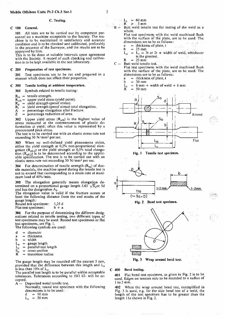
306 For the purpose of determining the different designations related to tensile testing, two different types of test specimens may be used: Round test specimens or flat test specimens, see Fig. I. The following symbols are used:
d = diameter a = thickness b ~ width L 0 - gauge length Le ~ parallel test length S0 = cross-section R = transition radius
The gauge length may be rounded off the nearest 5 mm, provided that the difference between this length and L0
is less than I 0% of L 0 •
The parallel test length is to be parallel within acceptable tolerances. Tolerances according to ISO 82- will be accepted. A - Deposited metal tensile test.
Normally, round test specimen with the following dimensions is to be used: d ~ IO mm L0 ~ 50mm
2
Le ~ 60 mm R ~ 5mm
B - Butt ·weld tensile test for testing of the weld as a whole. Flat test specimens with the weld machined flush with the surface of the plate, are to be used. The dimensions are to be as follows: a ~ thickness of plate, t b ~ 25 mm L0 ~ Le ~ 3t or 2t + width of weld, whichever
is the greatest. R ~ 25 mm
C - Butt weld tensile test. Flat test specimens ·with the weld machined flush with the surface of the plate, are to be used. The dimensions are to be as follows: a ~ thickness of plate, t b ~ 30 mm Le ~ 6 mm+ width of weld+ 6 mm R ~ 50mm
R So
d
So / b
·-·
11 r;i
l.t- Lo ' ·I.I Le
Fig. t Tensile test specimen.
Flat
-.J_ 1· b ·1 01 t. "0 .I~
(~Sa+D)
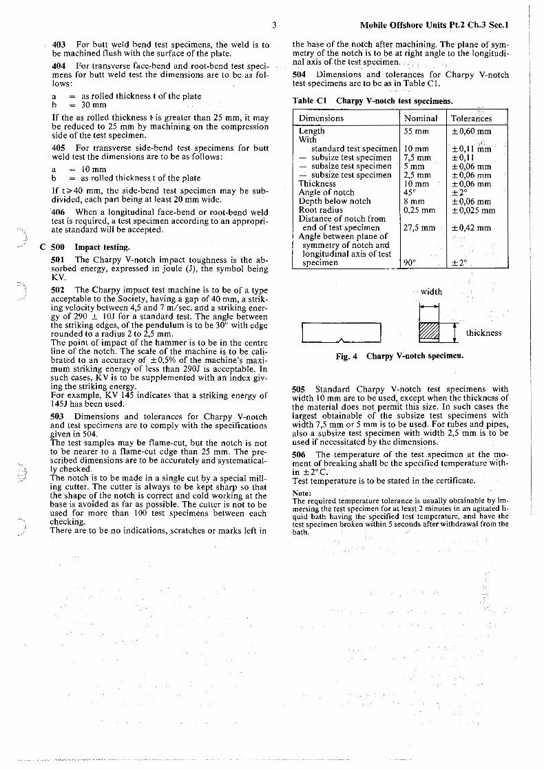
Fig. 2 Bend test specimen.
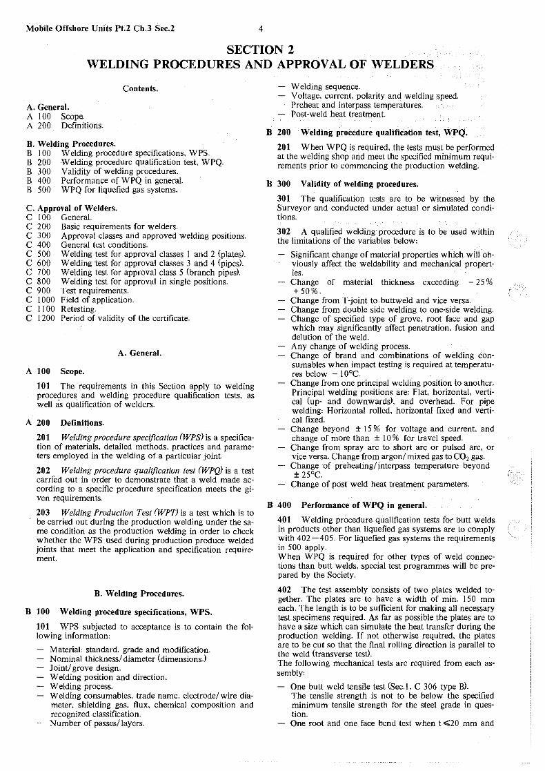
Fig. 3 Wrap around bend test.
C 400 Bend testing. 401 Flat bend test specimen, as given in Fig. 2 is to be used. Edges on tension side to be rounded to a radius of I to 2 mm. 402 When the wrap around bend test, exemplified in Fig. 3 is used, e.g. for the side bend test of a weld, the length of the test specimen has to be greater than the length 11 a shown in Fig. 2.
403 For butt weld bend test specimens, the weld is to be machined flush with the surface of the plate.
404 For transverse face-bend and root-bend test specimens for butt weld test the dimensions are to be as follows:
a ~ as rolled thickness t of the plate b ~ 30mm
If the as rolled thickness ; is greater than 25 mm, it may be reduced to 25 mm by machining on the compression side of the test specimen.
405 For transverse side-bend test specimens for butt weld test the dimensions are to be as follows:
a ~ 10 mm b ~ as rolled thickness t of the plate
If t;.40 mm, the side-bend test specimen may be subdivided, each part being at least 20 mm wide.
406 When a longitudinal face-bend or root-bend weld test is required, a test specimen according to an appropriate standard will be accepted.
C 500 Impact testing.
501 The Charpy V-notch impact toughness is the absorbed energy, expressed in joule (J), the symbol being KV.
502 The Charpy impact test machine is to be of a type acceptable to the Society, having a gap of 40 mm, a striking velocity between 4,5 and 7 m/sec. and a striking energy of 290 ± I OJ for a standard test. The angle between the striking edges, of the pendulum is to be 30° with edge rounded to a radius 2 to 2,5 mm. The point of impact of the hammer is to be in the centre line of the notch. The scale of the machine is to be calibrated to an accuracy of ± O,So/o of the machine's maximum striking energy of less than 290J is acceptable. In such cases, KV is to be supplemented with an index giving the striking energy. For example, KV I 45 indicates that a striking energy of I 45J has been used.
503 Dimensions and tolerances for Charpy V-notch and test specimens are to comply with the specifications given in 504. The test samples may be flame-cut, but the notch is not to be nearer to a flame-cut edge than 25 mm. The prescribed dimensions are to be accurately and systematically checked. The notch is to be made in a single cut by a special milling cutter. The cutter is always to be kept sharp so that the shape of the notch is correct and cold working at the base is avoided as far as possible. The cutter is not to be used for more than 100 test specimens between each checking. There are to be no indications, scratches or marks left in
3 Mobile Offshore Units Pt.2 Ch.3 Sec.I
the base of the notch after machining. The plane of symmetry of the notch is to be at right angle to the longitudinal axis of the. test specimen.
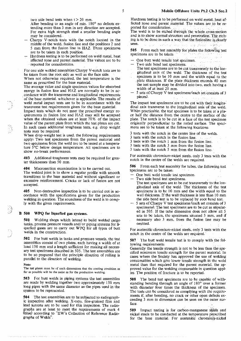
504 Dimensions and tolerances for Charpy V-notch test specimens are to be as in Table Cl.
Table Cl Charpy V-notch test specimens.
Dimensions Nominal Tolerarices
Length 55 mm ±0,60 mm With - standard test specimen !Omm ±0,J I mm - subsize test specimen 7,5mm ±0,11 - subsize test specimen 5mm ±0,06mm - subsize test specimen 2,5mm ±0,06mm Thickness IO mm ±0,06mm Angle of notch 45° ±20 Depth below notch Smm ±0,06mm Root radius 0,25 mm ±0,025 mm Distance of notch from end of test specimen 27,5 mm ±0,42 mm
Angle between plane of symmetry of nbtch antl longitudinal axis of test specimen 90° ±20
width
~ thickness
Fig. 4 Charpy V-notch specimen.
505 Standard Charpy V-notch test specimens with width I 0 mm are to be used, except when the thickness of the material does not permit this size. In such cases the largest obtainable of the subsize test specimens with width 7,5 mm or 5 mm is to be used. For tubes and pipes, also a subsize test specimen with width 2,5 mm is to be used if necessitated by the dimensions.
506 The temperature of the test specimen at the moment of breaking shall be the specified temperature within ±2°C. Test temperature is to be stated in the certificate.
Note: The required temperature tolerance is usually obtainable by immersing the test specimen for at least 2 minutes in an agitated liquid bath having the specified test temperature, and have the test specimen broken within 5 seconds after withdrawal from the bath.
Mobile Offshore Units Pt.2 Ch.3 Sec.2 4
SECTION 2 WELDING PROCEDURES AND APPROVAL OF WELDERS
Contents.
A. General. A 100 Scope. A 200 Definitions.
B. Welding Procedures. B I 00 Welding procedure specifications. WPS. B 200 Welding procedure qualification test, WPQ. B 300 Validity of welding procedures. B 400 Performance of WPQ in general. B 500 WPQ for liquefied gas systems.
C. Approval of Welders. C I 00 General. C 200 Basic requirements for welders. C JOO Approval classes and approved welding positions. C 400 General test conditions. C 500 Welding test for approval classes I and 2 (plates). C 600 Welding test for approval classes 3 and 4 (pipes). C 700 Welding test for approval class 5 (branch pipes). C 800 Welding test for approval in single positions. C 900 Test requirements. C I 000 Field of application. C 11 00 Retesting. C 1200 Period of validity of the certificate.
A. General.
A 100 Scope.
101 The requirements in this Section apply to welding procedures and welding procedure qualification tests, as well as qualification of welders.
A 200 Definitions.
201 Welding procedure specification (WPS) is a specification of materials, detailed methods, practices and parameters employed in the welding of a particular joint.
202 Welding procedure qualification test (WPQ) is a test carried out in order to demonstrate that a weld made according to a specific procedure specification meets the given requirements.
203 Welding Production Test (WPT) is a test which is to be carried out during the production welding under the same condition as the production welding in order to check whether the WPS used during production produce welded joints that meet the application and specification requirement.
B. Welding Procedures.
B 100 Welding procedure specifications, WPS.
101 WPS subjected to acceptance is to contain the following information:
Material: standard, grade and modification. Nominal thickness/ diameter (dimensions.) Joint/ grove design. Welding position and direction. Welding process. Welding consumables, trade name, electrode/ wire diameter. shielding gas, flux. chemical composition and recognized classification. Number of passes/layers.
Welding sequence. Voltage, current, polarity and welding speed. Preheat and interpass temperatures. Post-weld heat treatment.
B 200 Welding procedure qualification test, WPQ.
201 When WPQ is required, the tests must be performed at the welding shop and meet the specified minimum requirements prior to commencing the production welding.
B 300 Validity of welding procedures.
30 I The qualification tests are to be witnessed by the Surveyor and conducted under actual or simulated conditions.
302 A qualified welding procedure is to be used within the limitations of the variables below:
Significant change of material properties which will obviously affect the weldability and mechanical properties. Change of material thickness exceeding - 25 % + 50%.
Change from T-joint to buttweld and vice versa. Change from double side welding to one-side welding. Change of specified type of grove, root face and gap which may significantly affect penetration. fusion and delution of the weld. Any change of welding process. Change of brand and combinations of welding consumables when impact testing is required at temperatures below - I 0°C. Change from one principal welding position to another. Principal welding positions are: Flat, horizontal, vertical (up- and downwards), and overhead. For pipe welding: Horizontal rolled, horizontal fixed and vertical fixed. Change beyond ± 15 % for voltage and current. and change of more than ± I 0 % for travel speed. Change from spray arc to short arc or pulsed arc. or vice versa. Change from argon/ mixed gas to C02 gas. Change of preheating/ interpass temperature beyond ± 25°C.
Change of post weld heat treatment parameters.
B 400 Performance of WPQ in general.
401 Welding procedure qualification tests for butt welds in products other than liquefied gas systems are to comply with 402-405. For liquefied gas systems the requirements in 500 apply. When WPQ is required for other types of weld connections than butt welds, special test programmes will be prepared by the Society.
402 The test assembly consists of two plates welded together. The plates are to have a width of min. 150 mm each. The length is to be sufficient for making all necessary test specimens required. As far as possible the plates are to have a size which can simulate the heat transfer during the production welding. If not otherwise required, the plates are to be cut so that the final rolling direction is parallel to the weld (transverse test). The following mechanical tests are required from each assembly'
One butt weld tensile test <sec. I. C 306 type B). The tensile strength is not to be below the specified minimum tensile strength for the steel grade in question. One root and one face bend test when t .:=s;;;:20 mm and
(
two side bend tests when t > 20 mm. After bending to an angle of min. 180° no defects extending more than 3 mm in any direction are accepted. For extra high strength steel a smaller bending angle may be considered. Charpy V-notch tests with the notch located in the middle of the weld, fusion line and the positions 2 and 5 mm from the fusion line in HAZ. Thre.e specimens are to be taken in each position. Hardness testing is to be performed on weld metal, heat affected zone and parent material. The values are to be reported for consideration.
For one side welded assemblies Charpy V-notch tests are to be taken from the root side as well as the face side. When not otherwise required. the test temperature is the same as prescribed for the base material. The average value and single specimen values for absorbed energy in fusion line and HAZ are normally to be in accordance with the transverse and longitudinal requirements of the base material, whichever is applicable. The results of weld metal impact tests are to be in accordance with the transverse test requirements given for the base material. Impact tests which do not meet the prescribed energy requirements in fusion line and HAZ may still be accepted when the obtained values are at least 70 % of the impact value of the parent plate from which the test plates are cut. In such cases additional toughness tests, e.g. drop weight tests may be required. When drop-weight test is used, the following requirements apply: Two test specimens from the parent material and two specimens from the weld are to be tested at a temperature 5°C below design temperature. All specimens are to show no-break performance.
403 Additional toughness tests may be required for greater thicknesses than 50 mm.
404 Macrosection examination is to be carried out. The welded joint is to show a regular profile with smooth transitions to the base material and without significant or excessive reinforcement. Cracks or lack of fusion are not accepted.
405 Non-destructive inspection is to be carried out in accordance with the specification Riven for the production welding in question. The soundness of the weld is to comply with the given requirements.
B 500 WPQ for liquefied gas systems.
501 Welding shops which intend to build welded cargo tanks, process pressure vessels and/ or piping systems for liquefied gases are to carry out WPQ for all types of butt welds in the construction.
502 For butt welds in tanks and pressure vessels, the test assemblies consist of two plates, each having a width of at least 150 mm and .a length sufficient for making all necessary test specimens described in 505. The test assemblies are to be so prepared that the principle direction of rolling is parallel to the direction of welding.
Note: The test plates must be of such dimensions that the cooling condition as far as possible will be the same as for the production welding.
503 For butt welds in piping systems the test assemblies are made by welding together two approximately 150 mm long pipes with the same diameter as the pipes used in the system to be represented.
504 The test assemblies are to be subjected to radiographic inspection after welding. X-rays, fine-grained film and lead screens are to be used for this inspection. The radiographs are at least to meet the requirements of mark 4 (blue) according to "IIW's Collection of Reference Radiographs of Welds".
5 Mobile Offshore Units Pt.2 Ch.3 Sec.2
Hardness testing is to be performed on weld metal, heat affected zone and parent material. The values are to be reported for consideration. The weld is to be etched through the whole cross,section and is to show normal structure and penetration. The etching is to be done in such a way that the fusioritine i§_:Plearly seen.
505 From each test assembly for plates the follo~Ihgtest specimens are to be taken:
One Putt weld. tensile test specimen. Two side bend test specimens. The test specimens are to be cut transversely to the longitudinal axis of the weld. The thickness of the test specimen is to be 10 mm and the width equal to the plate thickness. If the plate thickness exceeds 40 mm the test sample may be divided into two, each having a width of at least 20 mm. 5 sets of Charpy V test specimens (each set consists of 3 pieces).
The impact test specimens are to be cut with their longitudinal axis transverse to the longitudinal axis of the weld. When practicable, the test specimen is to be taken at a place half the distance from the centre to the surface of the plate. The notch is to be cut in a face of the-test specimen originally perpendicular to the rolled surface. The specimens are to be taken at the following locations:
3 tests with the notch in the centre line of the welds. 3 tests with the notch in the fusion line. 3 tests with the notch 1 mm from the fusion line. 3 tests with the notch 3 mm from the fusion line. 3 tests with the notch 5 mm from the fusion line.
For austenitic chromium-nickel steels, only 3 tests with the notch in the centre of the welds are required.
506 From each test assembly for tubes, the following test specimens are to be taken:
One butt weld tensile test specimen. Two side bend test specimens. The test specimens are to be cut transversely to the longitudinal axis of the weld. The thickness of the test specimens is to be 10 mm and the width equal to the wall thickness. If the wall thickness is less than 10 mm the side bend test is to be replaced by root bend test. 5 sets of Charpy V test specimens (each set consists of 3 specimens). The test specimens are to be cut as stipulated in 505. If the tube dimension does not allow all 5 sets to be taken, the specimens situated 5 mm, and if necessary also 3 mm, from the fusion line may. be omitted.
For austenitic chromium-nickel steels, only 3 tests with the notch in the centre of the welds are required.
507 The butt weld tensile test is to comply with the following requirements: Generally the tensile strength is not to be less than the specified minimum tensile strength for the parent material. In cases where the Society has approved the use of welding consumables which give lower tensile strength in the weld metal than that required for the parent material, the approved value for the welding consumable in question applies. The position of fracture is to be reported.
508 The bend test specimens are to be capable of withstanding bending through an angle of 180°· over a former with diameter four times the thickness of the specimen. The tests can be considered as complying with the requirements if, after bending, no crack or other open defects exceeding 3 mm in dimension can be seen on the outer surface.
509 Impact testing is for carbon-manganese steels and nickel steels to be conducted at the temperature pr:escribed for the base material. For austenitic chromiu.f4-nickel

Mobile Offshore Units Pt.2 Ch.3 Sec.2
steels, testing is to be conducted at a temperature at least 5°C below the design temperature in question. For welding of plates the following apply, When specimens of I 0 x I 0 mm cross-section are used, the average value from 3 tests is not to be less than 271 for weld metal. fusion line. heat affected zone and parent material. One single test may give a value below the required average, but not lower than I SJ. For welding of tubes the following apply' When specimens of I 0 x 10 mm cross section are used the average value from 3 tests is for weld metal not to be less than 271. One single test may give a value below the required average, but not lower than 18J. For fusion line. heat affected zone and parent material the average value from 3 tests is not to be less than 271 for carbon-manganese steels and 341 for nickel steels. The corresponding minimum single values are I SJ and 231. For testing of thin materials where it is impossible to use a standard test specimen I 0 x I 0 mm. the larger of the following specimens is to be used: IO x 7,5 mm, IO x 5 mm, IO x 2.5 mm. The impact values are then reduced to respectively 5 I 6, 2/3 and 1/2 of the required values of the standard test specimen.
C. Approval of Welders.
C 100 General.
101 The subsequent Rule requirements and test programs apply to approval of welders for welding operations on steel structures of unalloyed and low-alloyed steel with reasonable weldability. The Rules are based on methods given in 102. For other welding methods the welder is to carry out separate approval tests in accordance with a program specified by the Society.
102 The following welding methods are covered by the approval tests specified in the Rules'
arc welding with covered electrodes. arc welding with flux-cored wire without external gas shielding. gas shielded metal arc welding with flux-cored wire. gas shielded metal arc welding with solid wire. gas shielded tungsten arc welding. gas welding. submerged arc welding.
103 For welding processes where the welder (welding operator) has minimal influence on the properties of the weld, no approval testing will be required except theoretical and practical training in accordance with 201 - 203. If the welder (welding operatorl has continual influence on the properties of the weld, an approval testing will be required.
104 Welders with certificate of approval issued by a recognized inspecting agency valid for welding operations comparable in severity to one or more of the approval classes specified in the Rules, may be approved by the Society for the relevant class without additional testing.
C 200 Basic requirements for welders.
201 The welder is to be at least 18 years of age. He is to have practical and theoretical training, normally in a trade school or welding school. The training is to include introduction to:
fundamental welding technique main fundamentals of steel welding metallurgy correct handling of welding and cutting equipment gouging and grinding electrode handling
6
potential health hazards fire hazards other hazards within the trade fire laws and regulations the purpose of welding procedure specifications the meaning and influence of different parameters welding procedure testing the aspects related to approval of welders usual methods of non destructive testing.
202 If the welder is without such training in school as stipulated in 20 I , he has to demonstrate his theoretical and practical skills in another way.
203 In addition to theoretical and practical training the welder is to have practised welding for at least one year. Shorter time of practice may, however. be accepted if it is proved that the welder in other ways has gained corresponding experience and skill.
204 The frequented school or the company where the welder is employed is to certify that the welder has undergone the theoretical and practical training required according to the above.
205 If the test is passed, a welder's approval certificate is to be issued to the welder. The certificate is to be confirmed by the company I school and Det norske Veritas or the inspecting agency representing this Society.
206 If the welding test<s) is (are) not accepted, the retest requirements given in l l 00 apply.
C 300 Approval classes and approved welding positions.
301 The rules specify five approval classes. Test program and field of application for each class are given in Table CI.
302 The welder may be approved for one or a limited number of welding postions. For such approval the test program and field of application given in Table C2 apply.
303 A separate approval test is required for each welding method stated in I 02. Special welding parameters as stated in 304 wiU require a new approval test.
304 If the welding work involves one or more of the following working conditions, a special approval _test is required. which is to be stated in the certificate:
welding of section thicknesses s = 3 mm or smaller welding with electrodes of the cellulose type change of welding direction in vertical position as opposed to the one used in the original testing change of the material transfer in shielded metal arc welding as opposed to the one used in the original testing (changes from short arc to spray arc and vice versa) combination of welding methods.
The test program, with the exception of the mentioned changes, is to be as specified el sew here in these Rules.
305 To obtain approval for welding of fillet welds, the welder is to carry out the test program in approval class I or for the welding positions in question.
306 Welders who have carried out approved procedure test<s) may on this basis be approved for the approval classes/ postions which the procedure tests are considered to cover in accordance with Table Cl and Table C2.
307 Extended approval testing may be required if the testing requirements for the specified approval classes are not considered to be representative for the welding work in question.
C 400 . General test conditions.
401 The welder is to follow a welding procedure specification where groove geometry and welding parameters are
realistic for the welding method and material thickness which are used for the approval testing. The total time for completing the welding is to correspond to the time for normal welding execution.
402 For manual arc welding with covered electrodes, low hydrogen, basic electrodes are to be used. All electrodes are to be welded to normal, short stub length.
403 The root pass is to be welded with at least one stop/ start in the groove. The electrode crater may be ground and small irregularities may be smoothed out. before proceeding. Chipping of the root is not allowed.
404 The test piece material is to be weldable killed or semi-killed carbon steel or C-Mn steel with specified minimum tensile strength Rm from 260 to 510 NI mm2.
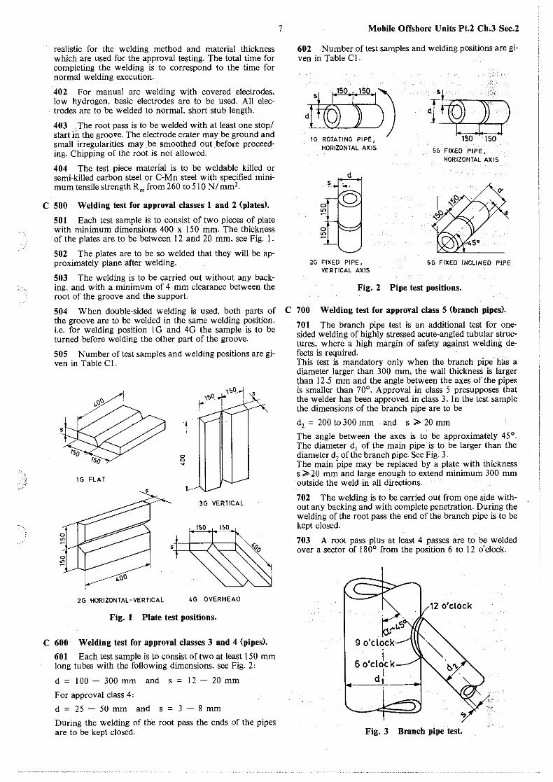
C 500 Welding test for approval classes 1 and 2 (plates).
501 Each test sample is to consist of two pieces of plate with minimum dimensions 400 x 150 mm. The thickness of the plates are to be between 12 and 20 mm, see Fig. 1.
502 The plates are to be so welded that they will be approximately plane after welding.
503 The welding is to be carried out without any backing, and with a minimum of 4 mm clearance between the root of the groove and the support.
504 When double-sided welding is used, both parts of the groove are to be welded in the same welding position, i.e. for welding position I G and 4G the sample is to be turned before welding the other part of the groove.
505 Number oftest samples and welding positions are given in Table Cl.
lG FLAT
1.00
2G HORIZONTAL-VERTICAL
0 0 ~
!.--3G VERTICAL
t.G OVERHEAD
Fig. I Plate test positions.
C 600 Welding test for approval classes 3 and 4 (pipes).
601 Each test sample is to consist of two at least 150 mm long tubes with the following dimensions. see Fig. 2,
d = 100 - 300 mm and s = 12 - 20 mm
For approval class 4,
d = 25 - 50 mm and s = 3 - 8 mm
During the welding of the root pass the ends of the pipes are to be kept closed.
7 Mobile Offshore Units Pt.2 Ch.3 Sec.2
602 Number oftest samples and welding positions are given in Table Cl.
'!@50,)50 I~ di ) )
150 . 150 1G ROTATING PIPE, HORIZONTAL AXIS 56 FIXED PIPE,
HORIZONTAL AXIS
Q'
2G FIXED PIPE, GP FIXED INCLINED PIPE VERTICAL AXIS
Fig. 2 Pipe test positions.
C 700 Welding test for approval class 5 (branch pipes).
701 The branch pipe test is an additional test for onesided welding of highly stressed acute-angled tubular structures, where a high margin of safety against welding defects is required. This test is mandatory only when the branch pipe has a diameter larger than 300 mm, the wall thickness is larger than 12,5 mm and the angle between the axes of the pipes is smaller than 70°. Approval in class 5 presupposes that the welder has been approved in class 3. In the test sample the dimensions of the branch pipe are to be
d2 = 200 to 300 mm and s ;;. 20 mm
The angle between the axes is to be approximately 45°. The diameter d1 of the main pipe is to be larger than the diameter d2 of the branch pipe. See Fig. 3. The main pipe may be replaced by a plate with thickness s ;;. 20 mm and large enough to extend minimum 300 mm outside the weld in all directions.
702 The welding is to be carried out from one side without any backing and with complete penetration. During the welding of the root pass the end of the branch pipe is to be kept closed.
703 A root pass plus at least 4 passes are to be welded over a sector of 180° from the position 6 to 12 o'clock.
9 o'clock
I 6 o'clock
ct)
12 o'clock
Fig. 3 Branch pipe test.
Mobile Offshore Units Pt.2 Ch.3 Sec.2
C 800 Welding test for approval in single welding positions.
801 For approval in one or a limited number of welding positions in accordance with Table C2, welding and test samples are to be as given in 400. 500 and 600.
C 900 Test requirements.
901 General. The test samples are to be subjected to visual examination, radiographic examination in accordance with IIW I llS-423-73 (plates) and IIW/IJS-492-75 (pipes and tubes). bend tests and visual examination of macrosections as spe· cified in Table CJ.
902 Visual evaluation. The welding reinforcement is to be of uniform width and height. Significant sharp and/ or deep undercuts or cold laps are not acceptable. The reinforcement of the weld is everywhere to be positive, but not larger than 3 mm. By welding from one side the penetration is to be complete with maximum 2 mm excess materiai.
903 Evaluation of radiographs. Weld defects are not to occur to a greater extent than corresponding to grade 4 (blue) in accordance with IIW's/IIS' «Collection of Reference Radiographs of Welds», latest edition. For plates, 30 mm at each end is not taken into consideration.
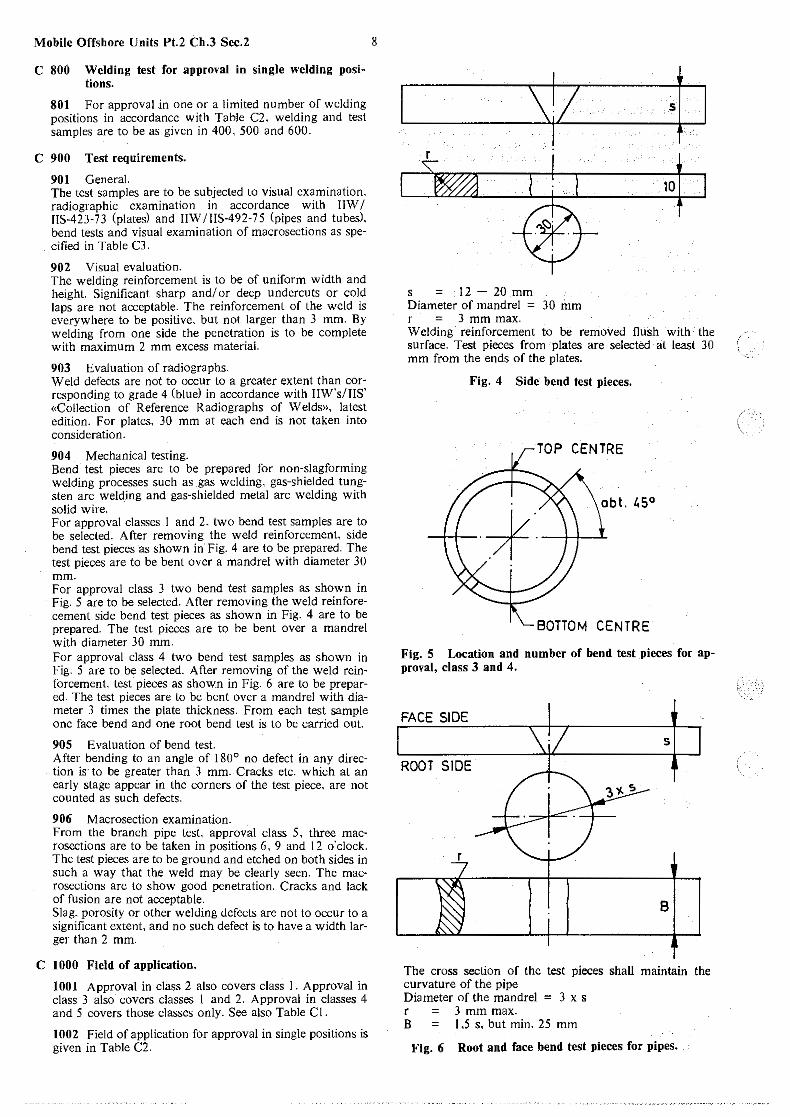
904 Mechanical testing. Bend test pieces are to be prepared for non-slagforming welding processes such as _gas welding, gas-shielded tungsten arc welding and gas-shielded metal arc welding with solid wire. For approval classes 1 and 2, two bend test samples are to be selected. After removing the weld reinforcement, side bend test pieces as shown in· Fig. 4 are to be prepared. The test pieces are to be bent over a mandrel with diameter 30 mm. For approval class 3 two bend test samples as shown in Fig. 5 are to be selected. After removing the weld reinforecement side bend test pieces as shown in Fig. 4 are to be prepared. The test pieces are to be bent over a mandrel with diameter 30 mm. For approval class 4 two bend test samples as shown in Fig. 5 are to be selected. After removing of the weld reinforcement. test pieces as shown in Fig. 6 are to be prepared. The test pieces are to be bent over a mandrel with diameter 3 times the plate thickness. From each test sample one face bend and one root bend test is to be carried out.
905 Evaluation of bend test. After bending to an angle of 180° no defect in any direction is· to be greater than 3 mm.-Cracks etc. which at an early stage appear in the corners of the test piece, are not counted as such defects.
906 Macrosection examination. From the branch pipe test approval class 5, three macrosections are to be taken in positions 6, 9 and 12 o'clock. The test pieces are to be ground and etched on both sides in such a way that the weld may be clearly seen. The macrosections are to show good penetration. Cracks and lack of fusion are not acceptable. Slag. porosity or other welding defects are not to occur to a significant extent and no such defect is to have a width larger than 2 mm.
C 1000 Field of application.
1001 Approval in class 2 also covers class I. Approval in class 3 also covers classes I and 2. Approval in classes 4 and 5 covers those classes only. See also Table Cl.
1002 Field of application for approval in single positions is given in Table C2.
8
s;z ·1 10
s = 12 - 20 mm Diameter of mandrel = 30 mm r = 3 mm max. Welding reinforcement to be removed flush with the surface. Test pieces from plates are selected at least 30 mm from the ends of the plates.
Fig. 4 Side bend test pieces.
TOP CENTRE
BOTTOM CENTRE
Fig. 5 Location and number of bend test pieces for approval, class 3 and 4.
FACE SIDE
5
ROOT SIDE
B
The cross section of the test pieces shall maintain the curvature of the pipe Diameter of the mandrel = 3 x s r = 3 mm max. B = 1.5 s. but min. 25 mm
Fig. 6 Root and face bend test pieces for pipes.
/ \
C 1100 Retesting.
1101 If 1 (one) test sample fails to fulfil the requirements. two new test samples of the same type may be welded: The test is considered passed if both these tests are satisfactory.
1102 If two or more test samples fail to fulfil the requireme:qts, the test is considered not passed.
1103 If the test is not passed, a new test cannot be taken until at least one week of instruction and training has been undertaken.
C 1200 Period of validity of the certificate.
1201 The approval is valid as long as it can be documented that the welder has carried out qualified work with acceptable welding performance, and no interruption has been longer than 6 months.
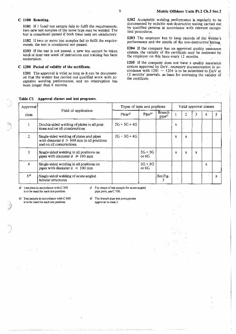
Table Cl Approval classes and test programs.
Approval Field of application
class
9 Mobile Offshore Units Pt.2 Ch.3 Sec.2
1202 Acceptable welding performance is regularly to be documented by suitable -non-destructive testing carried _out by qualified persons in accordance with relevant recognized procedures.
1203 The employer has to keep records of the Welder's performance and the results of the non-destructive-testing.
" 1204 If the company has an approved quality assurance system, the validity of the certificate may be endorsed by the employer on this basis every 12 months.
1205 If the company does not have a quality assurance system approved by Dn V, necessary documentation· in ·accordance with 1201 - 1204 is to be submitted to On V at 12 months· intervals. as basis for endorsing the validity of the certificate.
Types of tests and positions Valid approval Classes
Plate•l Branch Pipebl piped 1 2 3 4· 5
1 Double-sided welding of plates in all posi- 2G+ 3G+ 4G x tions and on all constructions
2 Single-sided welding of plates and pipes 2G+ 3G+ 4G with diameter d > 600 mm in all positions and on all constructions
3 Single-sided welding in all positions on 2G+5G pipes with diameter d ;» 100 mm or6G
4 Single-sided welding in all positions on 2G+5G pipes with diameter d < 100 mm or6G
5dl Single-sided welding of acute-angled tubular structures
a) Test plate in accordance with C 500 is to be used for each test position.
c) For shape of test sample for acute-angled pipe joint. see C 700.
b) Test sample in accordance with C 600 -is to be used for each test position.
ct) The branch pipe test presupposes approval in class 3.
x x
x x x
x
See Fig. x 3
Mobile Offshore Units Pt.2 Ch.3 Sec.2 10
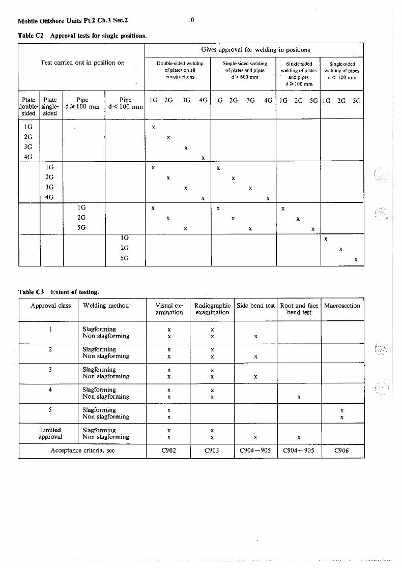
Table C2 Approval tests for single positions.
Gives approval for welding in positions
Test carried out in position on Double-sided welding Single-sided welding Single-sided Single-sided of plates on all of plates and pipes welding of plates welding of pipes constructions d> 600 mm and pipes d< 100 mm
d>IOOmm
Plate Plate Pipe Pipe lG 2G 3G 4G lG 2G 3G 4G lG 2G SG lG 2G SG double- single- d ;;> 100 mm ct< 100 mm sided sided
lG x
2G x
3G x
4G x IG x x 2G x x 3G x x 4G x x
lG x x x 2G x x x SG x x x
IG x
2G x SG x
Table C3 Extent of testing.
Approval class Welding method Visual ex- Radiographic Side bend test Root and face Macrosection amination examination bend test
1 Slag forming x x Non slagforming x x x
2 Slagforming x x Non slagforming x x x
3 Slagforming x x Non slagforming x x x
4 Slagforming x x Non slagforming x x x
5 Slagforming x x Non slagforming x x
Limited Slag forming x x approval Non slagforming x x x x
Acceptance criteria, see C902 C903 C904-905 C904-905 C906
11 Mobile Offshore Units Pt.2 Ch.3 Sec.3
SECTION 3 WELDING CONSUMABLES
Contents.
A. General. A 100 Scope. A 200 Upgra,ding.
B. Electrodes for Manual, Metal-Arc Welding. B I 00 General. B 200 All-weld-metal tests. B 300 All-weld-metal tensile tests. B 400 All-weld-metal impact tests. B 500 Butt weld tests. B 600 Butt weld tensile tests. B 700 Butt weld bend tests. B 800 Butt weld impact tests B 900 Hydrogen test. B I 000 Deep penetration electrodes. B 1100 Deep penetration butt weld tests. B 1200 Deep penetration fillet weld tests. B 1300 Electrodes designed for fillet welding. B 1400 Chemical analysis. B 1500 Periodical inspection of maker's works and annual
tests. B 1600 Additional tests. B 1700 Special requirements. B 1800 Branding of packages.
C. Wire Flux Combinations for Submerged Arc Welding. C I 00 General. C 200 Multi-run technique. C 300 Two-run technique. C 400 Chemical analysis. C 500 Periodical inspection of maker's works and annual
tests. C 600 Additional tests.
D. Combinations for Use in One-side Automatic Welding Processes.
D I 00 General. D 200 Number of test assemblies. D 300 Mechanical testing. D 400 Requirements. D 500 Macro and micro structure. D 600 Chemical analysis. D 700 Annual testing.
E. Wire-Gas Combinations and Wires for Automatic and Semi-Automatic Welding.
E I 00 General. E 200 Designation. E 300 All-weld-metal tests. E 400 All-weld-metal impact tests. E 500 Butt weld tests. E 600 Butt weld impact tests. E 700 Two-run technique assemblies. E 800 Two-run technique butt weld impact tests. E 900 Periodical inspection of manufacturer and annual
tests.
F. Combinations for Use in Electro-Slag and Electro-Gas Welding Processes.
F I 00 General. F 200 Mechanical and impact testing. F 300 Test results. F 400 Photomacrographs. F 500 Annual testing procedure.
G. Welding Consumables for Welding of Steel Grades NV 2-4 and NV 4-4 for Low-temperature Applications.
G I 00 General.
G 200 G 300 G 400 G 500
All-weld-metal and butt weld tensile tests. All-weld-metal and butt weld impact tests. Hydrogen tests. Annual tests.
H. Welding Consumables for Low-Alloy, Heat Resisting Steels (NV 7-1,7-2 and 7-3).
H I 00 General. H 200 Pre- and post-heating. H 300 All-weld-metal tensile tests. H 400 Butt weld tests. H 500 Chemical composition. H 600 Hydrogen test. H 700 Annual testing.
I. Welding Consumables for Welding of Steel Grades NV 20-00, NV 20-0, NV•20-l and NV 20-2.
I I 00 General. I 200 All-weld-metal tensile tests. I 300 Butt weld tensile tests. I 400 Butt weld bend tests. I 500 All-weld-metal and butt weld impact tests. I 600 Hydrogen test. I 700 Annual testing. I 800 Results. I 900 Other welding comsumables.
J. Welding Consumables for Welding of Normalized or Quenched and Tempered Structural Steels with Specified Yield Stress 420 NI mm2 and Higher.
J I 00 General. J 200 All-weld-metal tensile test. J 300 Butt weld tensile test. J 400 Butt weld bend test. J 500 All-weld-metal and butt weld impact test. J 600 Hydrogen testing. J 700 Chemical analysis. J 800 Annual tests.
A. General.
A 100 Scope.
101 The requirements in this Section specify various grades of welding consumables.
Note: Reference is made to List of Approved Manufacturers on «Welding Con· sumables and Shop Primers».
A 200 Upgrading.
201 An approved welding consumable may be granted a higher grade than that initially granted. provided that impact testing is carried out with satisfac.tory results at the temperature specified for the higher grade. However. for upgrading from Grade I <resp. I T/M/S) to Grade 3 (resp. Ill T/M/S) or from any Grade to Grade 2Y H/HH or 3Y H/HH (resp. IIY TIMIS or IllY T/M/S), Charpy V-notch impact tests are to be carried out on specitnens taken from butt weld assemblies (downhand. horizontal-vertical or vertical as applicable). in addition to the normal requirements for annual testing. Upgrading of electrodes from H to HH based upon the diffusible hydrogen content. may also be considered, provided that hydrogen tests are carried out in accordance with the requirements given in ;·B 900. Welding consumables which have not previously been subjected to the hydrogen test, are to be tested according to B 900 when upgrading to Grade 2Y H/HH or 3Y H/HH is applied for.
Mobile Offshore Units Pt.2 Ch.3 Sec.3
B. Electrodes for Manual, Metal-Arc Welding.
B 100 General.
IOI Electrodes for manual metal-arc welding will be approved subject to compliance with the following tests. The test assemblies are to be prepared in the presence of the Surveyor and all tests carried out under his supervision. All electrodes used during the tests are to be selected from the n1anufacturer's store by the Surveyor.
102 Electrodes will be divided into Grades I. 2 and 3 for normal strength steels (400-490 N/mml) and 2Y and 3Y for high strength steels. In addition. those electrodes which pass the hydrogen test as stipulated in B 900. will have the suffix H or HH added to the grade mark. Electrodes for high strength steels are to be hydrogen tested and are to satisfy the requirements for at least the suffix H. Electrodes which have satisfied the requirements of Grade 2, will also be considered as complying with Grade I requirements. and those which have satisfied the requirements of Grade 3. will be considered as complying with Grade t and 2 requirements.
I 03 The test welds are normally to be made on the material for which approval of the electrode is desired. Any grade of structural steel may, however. be used for the preparation of the all-weld-metal test assemblies.
I 04 Grade A steel may be used in the butt weld test assemblies for the approval of electrodes for welding of nor-1nal strength steel. but at the option of the manufacturer. Grades B or D steel may be used for Grade 2 electrode test assemblies and Grade E steel for Grade 3 electrode test assemblies.
105 For electrodes which are also to satisfy the Grades 2 Y and 3 Y requirements for welding of high strength steels. a carbon-manganese steel with a tensile strength Rm~ 490 NI mml is to_ be used in the butt weld test assemblies.
106 The welding current used is to be within the range recommended by the manufacturer. When an electrode is stated to be suitable for both A.C. and D.C. the test assemblies are to be welded with A.C.
107 All assemblies. the all-weld-metal tests as well as the butt weld tests. are to be rigidly clamped during welding.
108 All weld tests may be performed by the manufacturer or anyone appointed by him.
B 200 All-weld-metal tests.
201 Tensile and impact tests are to be made. under controlled conditions, on metal depositied from the electrodes.
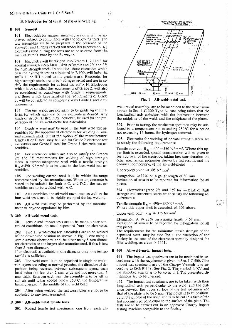
202 Two all-weld-metal test assemblies are to be welded in the downhand position as shown in Fig. I , one using 4 mm diameter electrodes. and the other using 8 mm diameter electrodes or the largest size manufactured. if this is less than 8 mm diameter. If an electrode is available in one diameter only, one test assembly is sufficient.
203 The weld metal is to be deposited in single or multirun layers according to normal practice. the direction of deposition being reversed between subsequent layers. each bead being not less than 2 mm wide and not more than 4 mm thick. Between eaCh run, the assembly is to be left in still air until it has cooled below 250°C. the temperature being checked in the middle of the weld bead.
204 After being welded. the test assemblies are not to be subjected to .any heat treatment.
B 300 All-weld-metal tensile tests.
301 Round tensile test specimens. one from each all-
12
3 IMPACT TEST -i"t- - jJ
~-- -,
SPECIMENS . - - --a NOTCH TAKEN AT MID -r'I- -{J PERt'ENDICULAR DEPTH OF WELD --""- - -' TO SURFACE (SEE FIG. 3) r -. -V OF PLA1'E
LINE OF CUT /I FOR TENSILE SPECIMEN --I
20 mm / MIN. t
I
c -~
E E
1TENSll.::0 TEST SPCCiM!:N
MIN.lOOmm 30mm, 91 MIN .100 mm
Fig. I AH-weld-metal test.
E
!i NI
weld-metal assembly, are to be machined to the dimensions shown in Sec. I C 300 Type A. care being taken that the longitudinal axis coincides with the intersection between the midplane of the weld. and the midplane of the plates.
302 Prior to testing. the tensile test specimen may be subjected to a temperature not exceeding 250°C for a period not exceeding 16 hours, for hydrogen removal.
303 Electrodes for welding of normal strength steels are to satisfy the following requirements:
Tensile strengtho Rm= 400-560 N/mm2. Where this upper limit is exceeded, special consideration will be given to the approval of the electrode. taking into consideration the other mechanical properties shown by test results. and the chemical composition of the all-weld-metal.
Upperyieldpointo ;;.305N/mm2.
Elongationo ;;. 22 % on a gauge length of 50 mm. Reduction of area is to be reported for information for all pieces.
304 Electrodes (grade 2Y and 3Y) for welding of high strength hull structural steels are to satisfy the following requirements:
TensilestrengthoRm = 490-660N/mm2.
Where this upper limit is exceeded. cf. 303 above.
Upper yield pointo R,H ;;. 375 NI mm2•
Elongationo A ;;. 22 % on a gauge length of 50 mm. Reduction of area is to be reported for information for all test pieces. The requirements for the minimum tensile strength of the deposited metal may be modified at the discretion of the· Society in the case of the electrodes specially designed for fillet welding. as given in 130 I .
B 400 AU-weld-metal impact tests.
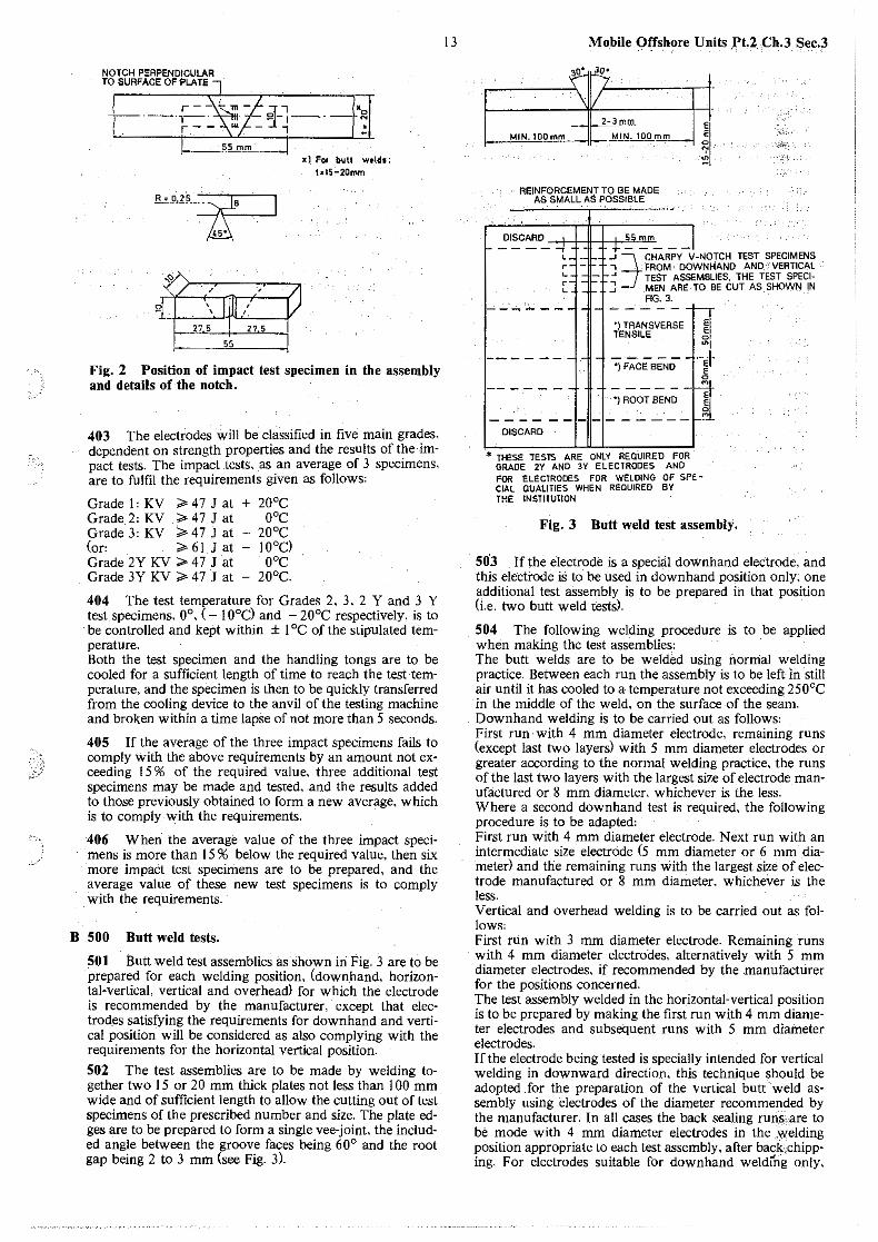
401 The impact test specimens are to be machined in accordance with the requirements given in Sec. I C 500. (The impact test specimens are of the Charpy V-notch type according to ISO/R 148. See Fig. 2. The symbol is KV and the absorbed energy is to be given in J).The prescribed dimensions are to be checked.
402 The impact test specimens are to be taken with their longitudinal axis perpendicular to the weld. and the distance between the upper surface of the test specimen and that of the plate is to be 5 mm. The notch is to be positioned in the middle of the weld and is to be cut in a face of the test specimen perpendicular to the surface of the plate. The tests are to be carried out in an approved Charpy impact testing machine acceptable to the Society.
(
(
NOTCH PERPENDICULAR TO SURFACE OF PLATE
~~Sml!l_
R;_Q,1?~~
'k1 ''
'o N
"
x l. For butt Wf'lds: t~IS-20mm
Fig. 2 Position of impact test specimen in the assembly and details of the notch.
403 The electrodes will be classified in five main grades. dependent on strength properties and the results of the -impact tests. The impact tests, as an average of 3 specimens, are to fulfil the requirements given as follows:
Grade l' KV ;;. 47 J at Grade 2, KV ;;. 47 J at Grade 3, KV ;;. 47 J at (or' ;;. 61 J at Grade 2Y KV ;;. 4 7 J at Grade 3Y KV ;;. 4 7 J at
+ 20°c 0°C
20°c 10°C) 0°C
20°c.
404 The test temperature for Grades 2, 3, 2 Y and 3 Y test specimens, 0°, ( - 10°C) and - 20°C respectively, is to be controlled and kept within ± 1 °C of the stipulated temperature. Both the test specimen and the handling tongs are to be cooled for a sufficient length of time to reach the test temperature, and the specimen is then to be quickly transferred from the cooling device to the anvil of the testing machine and broken within a time lapse of not more than 5 seconds.
405 If the average of the three impact specimens fails to comply with the above requirements by an amount not exceeding 15 % of the required value, three additional test specimens may be made and tested, and the results added to those previously obtained to form a new average, which is to comply with the requirements.
406 When the average value of the three impact specimens is more than 15 % below the required value, then six more impaCt test specimens are to be prepared, and the average value of these new test specimens is to comply with the requirements.
B 500 Butt weld tests.
501 Butt weld test assemblies as shown in Fig. 3 are to be prepared for each welding position. (downhand, horizontal-vertical, vertical and overheactl for which the electrode is recommended by the manufacturer, except that electrod_es satisfying the requirements for downhand and vertical position will be considered as also complying with the requirements for the horizontal vertical position.
502 The test assemblies are to be made by welding together two 15 or 20 mm thick plates not less than 100 mm wide and of sufficient length to allow the cutting out of test specimens of the prescribed number and size. The plate edges are to be prepared to form a single vee-joint, the included angle between the groove faces being 60° and the root gap being 2 to 3 mm (see Fig. 3).
13 Mo.bile Offshore Units .Pt.2. Ch.3 Sec.3
'" • J
' 7 . .
\ I/ .
2-3mm
MIN.100mm MIN. lOO_f!l.!!l__
REINFORCEMENT TO BE MADE AS SMALL AS POSSIBLE
...'.'':c~o__ J J ~ J ±SS mm __
;I .• ;:--
~·;•f!.'c
J;Xt
"- -c
" c
-' ?I CHARPY V-NOTCH TEST SPECIMENS I . FROM DOWN HANO AND 1 VERTICAL ~ TEST ASSEMBLIES, THE TEST SPECl-....1 MEN ARE TO BE CUT AS SHOWN IN
FIG. 3. -'--~.-.--
>m•~·-'~ TENSILE 0 ~
1 FAcEsENO e, ~' ------
*) ROOT' BEND ~ 0
DISCARD
.* THESE -lESTS ARE ONLY REQ.UJRED FOR GRADE 2Y ANO 3V ELECTRODES ANO FOR ELECTRODES FOR WELDING OF SPfCIAL QUALITIES WHEN REQUIRED BY THE INSTITUTION
Fig. 3 Butt weld test assembly.
503 If the electrode is a special downhand electrode, and this electrode iS to be used in downhand position only, one additional test assembly is to be prepared in that position (i.e. two butt weld tests).
504 The following welding procedure is to be applied when making the test assemblies: The butt welds are to be welded using normal welding practice. Between each run the assembly is to be left in still air until it has cooled to a temperature not exceeding 250°C in the middle of the weld, on the surface of the seam. Downhand welding is to be carried out as follows: First run with 4 mm diameter electrode, remaining runs (except last two layersl with 5 mm diameter electrodes or greater according to the normal welding practice, the runs of the last two layers with the largest size of electrode manufactured or 8 mm diameter, whichever is the less. Where a second downhand test is required, the following procedure is to be adapted: First run with 4 mm diameter electrode. Next run with an intermediate size electrode (5 mm diameter or 6 mm diameter) and the remaining runs with the largest size of electrode manufactured or 8 ·mm diameter, whichever is the less. Vertical and overhead welding is to be carried out as follows: First rt.in with 3 mm diameter electrode. Remaining runs with 4 mm diameter electrodes, alternatively with 5 mm diameter electrodes, if recommended by the .manufacturer for the positions concerned. The test assembly welded in the horizontal-vertical position is to be prepared by making the first run with 4 mm diameter electrodes and subsequent runs with 5 mm diameter electrodes. If the electrode being tested is specially intended for vertical welding in downward direction, this technique should be adopted .for the preparation of the vertical butt weld assembly using electrodes of the diameter recommended by the manufacturer. In all cases the back sealing run_s,,are to be mode with 4 mm diameter electrodes in the .welding position appropriate to each test assembly, after back,chipping, For electrodes suitable for downhand weldfng only,
Mobile Offshore Units Pt.2 Ch.3 Sec.3
the test assemblies may be turned over to weld the sealing run. After being welded. the test assemblies are not to be subjected to any heat treatment.
Note: It is advised that the welded assemblies be subjected to radiographic examination to ascertain whether there are any defects in the weld prior to testing.
505 The test specimens shown in Fig. 3 are to be prepared from each test assembly except that Charpy V-notch specimens are not required from assemblies welded in the overhead position.
B 600 Butt weld tensile tests.
601 Butt weld tensile tests are only required for electrodes for welding of high strength steels. i.e. for grades 2Y and 3Y.
602 Flat specimens of the form given in Sec. I C 300 Type C are to be prepared and may be degassed by heating to maximum 250°C as stipulated in B 302.
603 The upper and lower surface of the weld are to be filed. ground or machined flush with the plate surface.
604 The tensile strength of each test specimen is to be not less than 490 NI mm'. The position of fracture in the test specimen ·is to be reported.
B 700 Butt weld bend tests.
701 Butt weld bend tests are only required for electrodes for welding of high strength steels.
702 The specimens are to be 30 mm wide. The upper and lower surfaces of the Weld are to be filed. ground or machined flush with the surface of the plate. The sharp edges of the specimens are to be rounded to a radius not exceeding 2 mm.
703 One specimen from each welded assembly is to be tested with the face of the weld in tension and the other with the root of the weld in tension.
704 The test specimens are to be capable of withstanding bending through an angle of l 20°C over a former with diameter three times the thickness of the specimen. The test specimens can be considered as complying with the test requirements if. after bending. no crack or other open defect exceeding 3 mm in dimension can be seen on the outer surface.
B 800 Butt weld impact tests.
801 At least three Charpy V-notch impact test specimens (KV-type) are to be machined from each of the downhand. horizontal-vertical and vertical test assemblies.
802 The test specimens are to be prepared as shown in Fig. 2.
803 The test specimens are to be taken from the middle of the plate thickness with the notch perpendicular to the surface of the plate as shown in Fig. 2.
804 The results of the impact tests are to comply with the requirements given below:
Grade L KV ;;. 4 7 J at + 20°C for the test specimens from the as
sembly welded in the downhand and horizontalvertical position.
KV ;;. 27 J at + 20°C for the test specimens from the assembly welded in the vertical position.
Grade 2, KV ;;. 4 7 J at 0°C for the test specimens from the assemb
ly welded in the downhand and horizontal-vertical position.
14
KV ;;. 27 J at 0°C for the test specimens from the assembly welded in the vertical position.
Grade 3, KV ;;. 4 7 J at - 20°C for the test specimens from the as
sembly welded in the downhand and horizontalvertical position.
KV ;;. 27 J at - 20°C for the test specimens from the as-sembly welded in the vertical position.
Alternatively. testing may be carried out at - 10°C. In such cases. the test results will be specially considered for approval by the Society.
Grade 2y, KV ;;. 4 7 J at Q°C for the test specimens from the assemb
ly welded in the downhand and horizontal-vertical position.
KV ;;. 34 J at 0°C for the test pieces from the assembly welded in the vertical position.
Grade 3y, KV ;;. 4 7 J at - 20°C for the test specimens from the as
sembly welded in the downhand and horizontalvertical position.
KV ;;. 34 J at - 20°C for the test specimens from the assembly welded in the vertical position.
805 Retests are to be performed as stipulated in 405 and 406.
B 900 Hydrogen test.
9,01 Low hydrogen electrodes are to be submitted to a hydrogen test. The hydrogen test is to be carried out in accordance with the glycerine method prescribed below, or the mercury method prescribed in ISO 3690 - 1977. Suffixes HH or H will be added after the grade mark where the electrode is in compliance with the requirements that the amount of diffusible hydrogen content is not to exceed an average of 5 cm3 per 100 grammes or I 0 cm3 per I 00 grammes respectively for the four specimens tested by the glycerine method; and is not to exceed an average of 8 cmJ per 100 grammes or 15 cmlper 100 grammes respectively. for the four specimens tested by the mercury method. Alternative type of test. e.g. moisture test with appropriate maximum contents for total of all moisture. may be accepted subject to the special agreement with the Society.
902 Test procedure according to the glycerine method is given in 903-907.
903 Four test specimens are to be prepared measuring 12 x 25 mm in cross-section by about 125 mm in length. The parent·metal may be any grade of shipbuilding steel. Before welding, the specimens are to be weighed to the nearest 0,1 gram. On the 25 mm surface of each test specimen. a single weld bead about 100 mm in length is to be deposited by a 4 mm diameter electrode. using about 150 mm of the electrode. The welding is to be carried out with an arc as short as possible and with a current of approx. 150 amp. All four test specimens are to be welded within a period of 30 minutes. For iron powder electrodes, an electrode with a dimension giving approximately the same quantity of deposited metal ris an ordinary 4 mm diameter electrode is to be used. For each test specimen. a new electrode is to be used.
904 The electrodes, prior to welding, may undergo the normal drying process recommended by the manufacturer.
905 After welding each specimen, the following is to be carried out: 30 seconds after breaking of the arc. the specimen is quenched in water at approximately 20°C. When the specimen is cold. it is cleaned (all slag is to be completely removed) and placed in an apparatus suitable for the collection of hydrogen by displacement of glycerine. This last step has to be completed within 2 minutes after breaking the arc. The
glycerine is to be kept at a temperature of 45°C during the test. All specimens are to be welded and treated identically.
906 The specimens are to be kept immersed in the glycerine for a period of 48 hours and, after removal, are to be cleaned in water and alcohol. dried and weighed to the nearest 0.1 gram to determine the amount ofw'eld deposited.
907 The amount of gas given off in the course of the measuring period (48 hrs) is to be measured to the nearest 0,05 cmJ. corrected for temperature and pressure to 20°C and 760 mm Hg.
908 For a correct assessment and comparison of the electrodes. it is necessary to carry out all welds and other tests in an identical manner. Manufacturers wishing to have an electrode granted the suffix H or HH are to submit at least 4 electrodes - 4 mm diameter - to the Society's laboratory. through the local Surveyor.
B 1000 Deep penetration electrodes.
1001 If an electrode approved as a normal penetration electrode, is also desired approved as a deep penetration electrode for downhand butt welding and horizontal-vertical fillet welding. the additional tests stipulated in 1100 and 1200 are to be carried out.
1002 When a manufacturer states that an electrode. having deep penetrating properties, also can be used for downhand butt welding of thicker plates with bevelled edges, the electrode will be tested .as a normal penetration electrode. and the full series of tests in the downhand position are to be carried out. together with the deep penetration tests. stipulated in 1100 and 1200.
1003 When an electrode is recommended for deep penetration welding of butt joints and horizontal-vertical fillets only, the tests given in 1100 and 1200 only are required.
1004 Deep penetration electrodes will only be approved as Grade I electrodes. The suffix DP will be added.
1005 The manufacturer may recommend different welding parameters and procedures when using the same electrode both as a deep penetration and as a normal penetration electrode. The welding conditions pertaining to the penetration effect in question, are to be applied in each case when making the test specimens.
B 1100 Deep penetration butt weld tests.
1101 Two plates of thickness equal to twice the diameter of the core of the electrode plus 2 mm are to be butt welded together with one downhand run of welding from each side. The plates are not to be less than I 00 mm wide and of sufficient length to allow the cutting out of test specimens of the correct number and sizes as shown in Fig. 4. The plate material is to be of Grade NV A steel with a content of carbon not less than 0.18 % and sulphur not less than 0,03%.
1102 The joint edges are to be prepared square and smooth. The gap is not to exceed 0 .25 mm after the tack welding.
1103 The test assembly is to be welded with an 8 mm diameter electrode or the largest size manufactured if this is less than 8 mm diameter.
1104 After welding. the test assembly is to be cut to form two transverse tensile test specimens. tw·o bend test specimens and three Charpy V-notch impact test specimens.
1105 The discards at the ends of the welded assemblies are not to be more than 35 mm wide. The joints of these discards are to be polished and etched and are to show complete fusion and interpenetration of the welds. At each cut
15 Mobile Offshore Units Pt.2 Ch.3 Sec.3
in the test assembly, the joints are also to be examined to ensure that complete fusion has taken place.
1106 Two transverse butt weld flat tensile test specimens are to be prepared to the dimensions given in Sec. I C 300 Type C. The weld reinforcements are to be filed. ground or machined flush with the surface of the plate. The tensile strength of the test specimen is not to be less than 400 NI mm'.
0.25 mm
UfN.100m_m -_M_IN. "'"--
35 mm DISCARD -----·-t- -r - - ___ , ,_ -~ ::J... I
~;_1 _;~ :J , ._ __ -...J ------- ·------ .,
BEND'TEsT 5 -- - - - --·&----- - - f'1 .,
BEND TEST 5 -------!!------- f'1
TRANSVERSE TENSILE TEST
E E
0 ~
I- - - - - - - -I~ - - - -:- - - -I--
TRANSVERSE iENSILE TEST
E E ~
~-------~~------.._ 35 mm DISCARD.
CHARPY V-NOTCH TEST SPECIMENS FROM OOWNHANO ANO VERTICAL TEST ASSEMBLIES, THE TEST SPECIMEN ARE TO BE CUT AS SHOWN IN FIG. 2.
Fig. 4 Deep penetration butt weld tests.
1107 Two butt weld bend tests are to be prepared in accordance with the requirements in 700 and are to be capable of withstanding, without cracking. bending through an angle of 120° over a former with diameter three times the thickness of the specimen. One test specimen is to be subjected to face bending and the other to root bending.
1108 Three Charpy V-notch impact test specimens are to be prepared. The dimensions of the test specimens are to be as given in Sec. I C 500. The longitudinal axes of the test specimens are to be perpendicular to the direction of the weld. and they are to be taken from the middle of the plate thickness. The notch is to be in the midplane of the weld and is to be cut in a face of the test specimen perpendicular to the sur:face of the plate. The average impact value for the three specimens taken from the centre of the weld is not to be less than 4 7 J at about + 20oC.
B 1200 Deep penetration fillet weld tests.
1201 A fillet weld assembly is to be prepared as shown in Fig. 5 with plates about 12.5 mm in thickness. The material is to be of Grade NV A or similar with a content of carbon not less than. 0.18 % and sulphur not less than 0,03 % .
1202 The welding is to be carried out with one run for each fillet with plate A in the horizontal plane during the welding operations. The length of the fillet weld is to be 160 mm and the gap between the plates is not to exceed 0.25 mm.
Mobile Offshore Units Pt.2 Ch.3 Sec.3
1203 The filled weld on one side of the assembly is to be made with a 4 mm diameter electrode and that on the other side with the maximum size of electrode manufactured. The welding current used is to be within the range reco·mmended by the manufacturer and the welding is to be carried out using normal welding practice.
1204 The welded assembly is to be cut by sawing or machining about 35 mm from the ends of the fillet welds and the joints are to be ground, polished and etched.
1205 The welding of the fillet made with a 4 mm diameter electrode is tO shoW a penetration. of 4 mm.Csee Fig. 5) and the corresponding penetration of the fillet made with the maximum size of electrode manufactured is to be reported.
MAX. SIZE OF ELECTRODE MANUFACTURED
l o~ I I MIN.4mm ~~t l +-A
Fig. 5 Deep penetration fillet weld test.
B 1300 Electrodes designed for fillet welding.
1301 Where an electrode is submitted only for approval for fillet welding and to which the butt weld test required in 500 is not considered applicable, the initial approval tests should consist of the fillet weld tests given in 1302 and allweld-metal tests similar to those indicated in 200. Where an electrode is submitted for appoval for both butt and fillet welding. the initial approval tests may at the discretion of the Society include one fillet weld test as detailed in 1302 and welded in the horizontal-vertical postition.
1302 Fillet weld tests' Fillet weld assemblies as shown in Fig. 6, are to be prepared for each welding position (horizontal-vertical. vertical-upwards. vertical-downward or overhead) for which the electrode is recommended by the manufacturer. The test assemblies are to be welded using an electrode of a diameter recommended by the manufacturer for each welding position. The length of the test assemblies L is to be sufficient to allow at least the deposition of the entire length of the electrode being tested. The first side is to be welded using the maximum size of electrode manufactured and the second side is to be welded using the minimum size of electrode manufactured and recommended for fillet welding. The fillet size will in general be determined by the electrode size and the welding current employed during testing. In the case of approval of a fillet welding electrode using gravity or other similar contact welding devices, the fillet welding should be carried out using the welding process recommended by the manufacturer. with the longest size of the electrode manufactured. The manufacturer's recommended current range is to be reported for each electrode size. The weld test assembly is to be sectioned as shown in Fig. 6 to form three macro sections each about 25 mm thick, and hardness readings are to be made in each section as indicated in Fig. 7. The hardness of the weld is to be determined and is for grade 2 Y and 3 Y to meet the following listed equivalent values:
Diamond Pyramid Hardness (SO or I 00 N load), Rockwell (J 000 N loactl B'
150 minimum 80 minimum
For grades 1. 2 and 3 the hardness values are to be reported for information. The hardness of both heat affected zone (HAZ) and base metal is also to be determined and is to be reported for information. One of the remaining sections of the fillet weld is to have the weld on the first side gouged or machined to facilitate
16
breaking the fillet weld on the second side by closing the two plates together, subjecting the root of the weld to tension. On the other remaining section, the weld on the second side is to· be gouged or machined and the section fractured using the 'sa'me' procedure. ·The· fractured surfaces should be· examined and there shoUld be no evidence ofinComplete penetration. nor 'iilternal cracking ahd they should be reasonably free from porosity.
i .. , ' ., -0 I .r;;;I
'; '' '; '' '' '' '' '' '' '' '' '' '' '' '' '' ': ''
' 50 I ' About-112 l About 1/2L ·
'L
Fig. 6 Fillet weld test assembly.
E
~
BASE METAL
Fig. 7 Hardness readings.
B 1400 Chemical analysis.
1401 The chemical analysis of the weld metal made by the electrodes, includirig analysis for all significant alloying elements. is to be supplied by the manufacturer.
B 1500 Periodical inspection of maker's works and annual tests.
1501 All establishments where approved electrodes are manufactured and the associated quality control procedures are to be subject to annual inspection. On these occasions, samples of the approved electrodes are to be selected for testing and the testing is to be carried out as stipulated below.
1502 One tensile and three impact test specimens in duplicate are to be made from an.:weld-metal as stipulated in 300 and 400. One group of specimens is to be prepared with an electrode of 4 mm diameter and the other with an electrode not smaller than 4 mm diameter nor larger than 8 mm diameter.
1503 The tensile strength. yield stress and elongation are to be in accordance with 300 and the impact properties in accordance with 400 for the approved grade.
1504 For electrodes approved for downhand deep penetration butt welding and horizontal-vertical fillet welding, the tests are to be carried out as specified below.
1505 Two plates of thickness twice the core diameter of the electrode plus 2 mm are to be butt welded together with one downhand run from each side using a 6 mm diameter electrode or the largest size made if this is less than 6 mm diameter. The plates are to be not Jess than I 00 mm wide and of sufficient length to cut out one transverse tensile specimen. two bend test specimens and three Charpy V-notch impact test specimens.The notch in the impact test
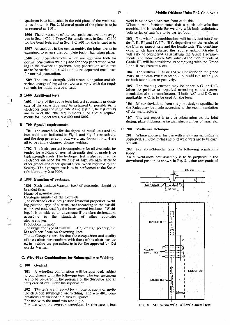
specimen is to be located in the mid-plane of the weld metal as shown in Fig. 2. Material grade of the plates is to be as required in l l 0 l.
1506 The dimensions of the test specimens are to be as given in Sec. l C 300 Type C for tensile tests. in Sec. l C 400 for the bend tests and in Sec. I C 500 for the impact tests.
1507 At each cut in the test assembly, the joints are to be examined to ensure that complete fusion has taken place.
1508 For those electrodes· which are approved both for normal penetration welding and for deep penetration welding in the downhand position, deep penetration weld tests are to be carried out in addition to the deposited metal tests for normal penetration.
1509 The tensile strength, yield stress. elongation and absorbed energy of impact test are to comply with the requirements for initial approval tests.
B 1600 Additional tests.
1601 If any of the above tests fail, test specimens in duplicate of the same type may be prepared (if possible using electrodes from the same batch) and tested. The test results are to meet the Rule requirements. (For special requirements for impact tests, see 400 and 800).
B 1700 Special requirements.
1701 The assemblies for the deposited metal tests and the butt weld tests indicated in Fig. 1 and Fig. 3 respectively, and the deep penetration butt weld test shown in Fig. 4 are all to be rigidly clamped during welding.
1702 The hydrogen test is compulsory for all electrodes intended for welding of normal strength steel of grade E or high strength steels. The hydrogen test is also required for electrodes intended for welding of high strength steels to other grades and other special steels, when required by the Society. The hydrogen test is to be performed at the Society's laboratory (see 900).
B 1800 Branding of packages.
1801 Each package (carton. boxl of electrodes should be branded thus: Name of manufacturer. Catalogue number of the electrode. The electrode's class designation (material properties, welding position, type of current, etc.) according to the classification and code used by the International Institute of Welding. It is considered an advantage if the class designations according to the standards of other countries also are given. Production number. The range and type of current - A.C. or D.C. polarity, etc. Maker's certificate on following lines: The ... Company certifies that the composition and quality of these electrodes conform with those of the electrodes used in making the prescribed tests for the approval by Det norske Veritas.
C. Wire-Flux Combinations for Submerged Arc Welding.
C 100 General.
101 A wire-flux combination will be approved, subject to compliance with the following tests. The test specimens are to be prepared in the presence of the Surveyor and all tests carried out under his supervision.
102 The tests are intended for automatic single or multiple electrode submerged arc welding. The wire-flux combinations are divided into two categories: For use with the multi-run techinque. For use with the two-run technique. In this case a butt
17 Mobile Offshore Units Pt.2 Ch.3 Sec.3
weld is made with one run from each side. When a manufacturer states that a particular wire-flux combination is suitable for welding with bcith techniques, both series of tests are to be carried o'ut.
103 The wire-flux combinations will be divided into Grades\, II. III and IY. IIY. IIIY. depending on the results of the Charpy impact tests and the tensile.tests. The combinations which have satisfied the requirements of Grade II. will aslo be considered as satisfying the Grade I requirements, and those which have satisfied the requirements of Grade III. will be considered as complying with the Grade I and II requirements, etc.
104 The sufftxes, T. M or TM will be added to the grade mark to indicate two-run technique, multi-run technique, or both techniques respectively.
105 The welding current may be either A.C. or D.C. (electrode positive or negative) according to the recommendation of the manufacturer. If both A.C. and D.C. are applicable, A.C. is to be used for the tests.
106 Minor deviations from the joint designs specified in the Rules may be made according to the recommendation of the manufacturer.
107 The test report is to give information on the joint design, plate thickness, wire diameter, number of runs, etc.
C 200 Multi-run technique.
201 Where approval for use with multi-run technique is requested, all-weld-metal and butt weld tests are to be carried out.
202 For all-weld-metal tests. the following regulations apply: An all-weld-metal test assembly is to be prepared in the downhand post.ion as shown in Fig. 8, using any grade of
TACK WELD
TENSILE TEST·
CHARPY IMPACT TEST
I I I I I I I
B"
TENSILE TEST
I
30
)0 10 10 10 IOI
I I
·r-LINE OF CUT
I I
Fig. 8 Multi-run weld. All-weld-metal test.
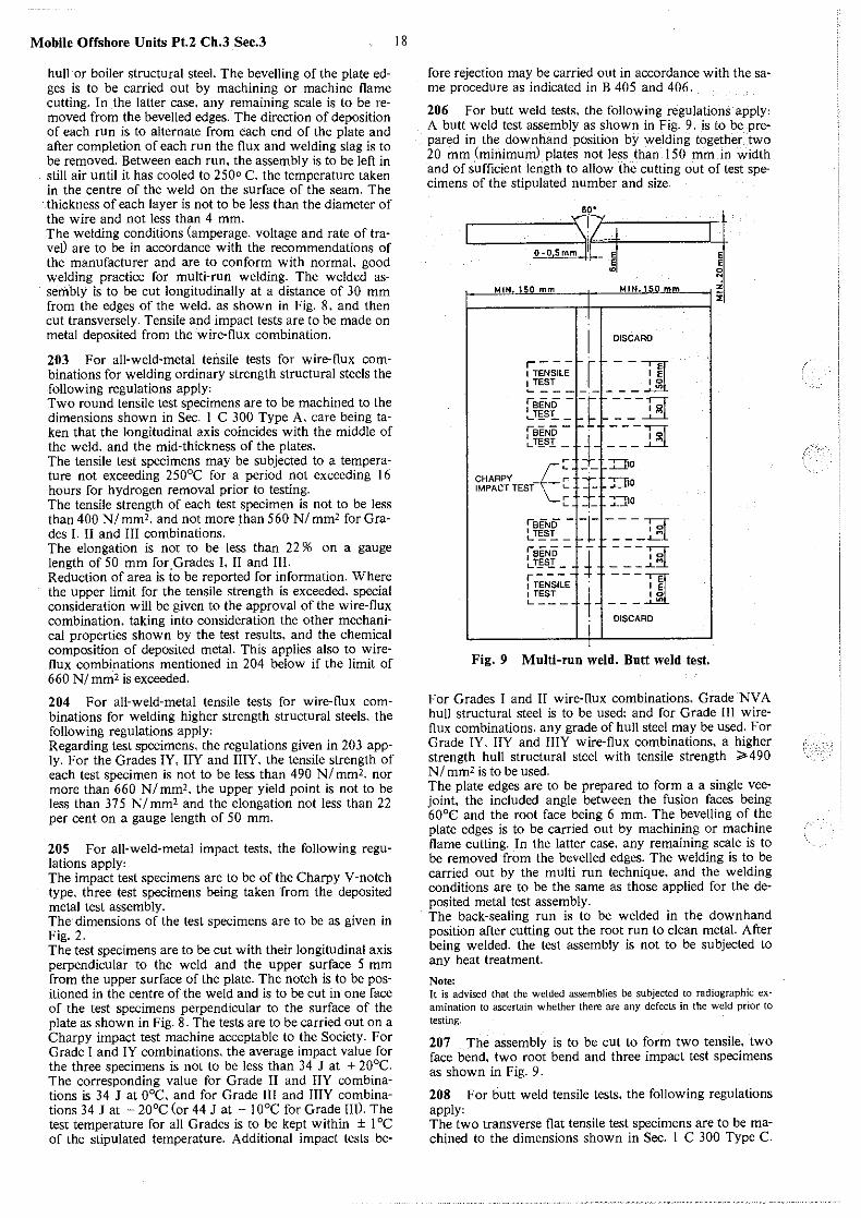
Mobile Offshore Units Pt.2 Ch.3 Sec.3
hull or boiler structural steel. The bevelling of the plate edges is to be carried out by machining or machine flame cutting. In the latter case, any re1naining scale is to be removed from the bevelled edges. The direction of deposition of each run is to alternate from each end of the plate and after completion of each run the flux and welding slag is to be removed. Between each run, the assembly is to be left in still air until it has cooled to 250° C. the temperature taken in the centre of the weld on the surface of the seam. The thickness of each layer is not to be less than the diameter of the wire and not less than 4 mm. The welding conditions (amperage, voltage and rate of trave0 are to be in accordance with the recommendations of the manufacturer and are to conform with normal. good welding practice for multi-run welding. The welded assembly is to be cut longitudinally at a distance of 30 mm from the edges of the weld. as shown in Fig. 8. and then cut transversely. Tensile and impact tests are to be made on metal deposited from the wire-flux combination.
203 For all-weld-metal tensile tests for wire-flux combinations for welding ordinary strength structural steels the following regulations apply, Two round tensile test specimens are to be machined to the dimensions shown in Sec. 1 C 300 Type A. care being taken that the longitudinal axis coincides with the middle of the weld. and the mid-thickness of the plates. The tensile test specimens may be subjected to a temperature not exceeding 250°C for a period not exceeding 16 hours for hydrogen removal prior to testing. The tensile strength of each test specimen is not to be less than 400 Nlmm'. and not more than 560 Nlmm' for Grades I. II and III combinations. The elongation is not to be less than 22 % on a gauge length of 50 mm for.Grades I. II and Ill. Reduction of area is to be reported for information. Where the upper limit for the tensile strength is exceeded. special consideration will be given to the approval of the wire-flux combination, taking into consideration the other mechanical properties shown by the test results, and the chemical composition of deposited metal. This applies also to wireflux combinations mentioned in 204 below if the limit of 660 NI mm' is exceeded.
204 For all-weld-metal tensile tests for wire-flux combinations for welding higher strength structural steels, the following regulations apply, Regarding test specimens, the regulations given in 203 apply. For the Grades IY. IIY and IIIY. the tensile strength of each test specimen is not to be less than 490 NI mm'. nor more than 660 NI mm'. the upper yield point is not to be less than 375 Nlmm' and the elongation not less than 22 per cent on a gauge length of 50 mm.
205 For all-weld-metal impact tests. the following regulations apply, The impact test specimens are to be of the Charpy V-notch type. three test specimens being taken from the deposited metal test assembly. The· dimensions of the test specimens are to be as given in Fig. 2. The test specimens are to be cut with their longitudinal axis perpendicular to the weld and the upper surface 5 mm from the upper surface of the plate. The notch is to be positioned in the centre of the weld and is to be cut in one face of the test specimens perpendicular to the surface of the plate as shown in Fig. 8. The tests are to be carried out on a Charpy impact test machine acceptable to the Society. For Grade I and IY combinations, the average impact value for the three specimens is not to be less than 34 J at + 20°C. The corresponding value for Grade II and IIY combinations is 34 J at 0°C, and for Grade Ill and IIIY combinations 34 J at - 20°C (or 44 J at - 10°C for Grade III). The test temperature for all Grades is to be kept within ± 1 °C of the stipulated temperature. Additional impact tests be-
18
fore rejection may be carried out in accordance with the same procedure as indicated in B 405 and 406.
206 For butt weld tests. the following regulations apply, A butt weld test assembly as shown in Fig. 9. is to be prepared in the downhand position by welding together two 20 mm (minimum) plates not less than 150 mm in width and of sufficient length to allow the cutting out of test specimens of the stipulated number and size.
_ El !I Ni
WI
I MIN. 150 mm I MIN.150 mm I ~: I I
I DISCARD
ir~;;L; I - - Jl[~ 1TEST I 1& '----------1.. ;sEND - -r ---p LT;_S!_ _ t- __ ~ feENi5 - i':"" - - -TcJ L_T£SI_ ---~
:: __ TI10
CHAAPY r r I .,..-.,; IMPACT TEST-(--'"- - _.__i!O
\__r •"110 L.. - - -'--·-l
i•END -1-c- ---;;;f ._T~S!_ _ _ _ -~1
,-,--- - ---~ 1 BEND 10
~T~S!.: J -::__:-=-'-..,
l TENSILE ~· TI[~ 1TEST 10 L--- --- LI'>
DISCARD
I I
Fig. 9 Multi-run weld. Butt weld test.
For Grades I and II wire-flux combinations. Grade NV A hull structural steel is to be used; and for Grade Ill wireflux combinations. any grade of hull steel may be used. For Grade IY. IIY and IIIY wire-flux combinations. a higher strength hull structural steel with tensile strength ;;. 490 NI mm' is to be used. The plate edges are to be prepared to form a a single veejoint. the included angle between the fusion faces being 60°C and the root face being 6 mm. The bevelling of the plate edges is to be carried out by machining or machine flame cutting. In the latter case, any remaining scale is to be removed from the bevelled edges. The welding is to be carried out by the multi run technique, and the welding conditions are to be the same as those applied for the deposited metal test assembly. The back-sealing run is to be welded in the downhand position after cutting out the root run to clean metal. After being welded. the test assembly is not to be subjected to any heat treatment.
Note: It is advised that the welded assemblies be subjected to radiographic examination to ascertain whether there are any defects in the weld prior to testing.
207 The assembly is to be cut to form two tensile. two face bend, two root bend and three impact test specimens as shown in Fig. 9.
208 For butt weld tensile tests, the following regulations apply, The two transverse flat tensile test specimens are to be machined to the dimensions shown in Sec. 1 C 300 Type C.
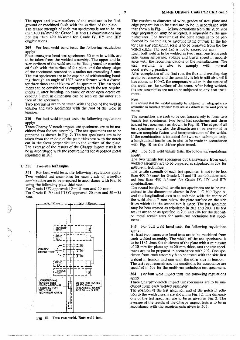
The upper and lower surfaces of the weld are to be filed, ground or machined flush with the surface of the plate. The tensile strength of each test specimens is not to be less than 400 NI mm' for Grade I. II and III combinations and not less than 490 NI mm' for Grade JY, IIY and IIIY combinations.
209 For butt weld bend tests, the following regulations apply' Four transv.erse bend test specimens, 3 0 mm in width, are to be taken from the welded assembly. The upper and lower surfaces of the weld are to be filed, ground or machined flush with the surface of the plate, and the sharp edges of the specimens rounded to a radius not exceeding 2 mm. The test specimens are to be capable of withstanding bending through an angle of 120° over a former with a diameter three times the thickness of the specimen. The test specimens can be considered as complying with the test requirements if. after bending. no crack or other open defect exceeding 3 mm in dimension can be seen on the outer surface of the specimen. Two specimens are to be tested with the face of the weld in tension and two specimens with the root of the weld in tension.
210 For butt weld impact tests, the following regulations apply' Three Charpy V-notch impact test specimens are to be machined from the test assembly. The test specimens are to be prepared as shown in Fig. 2. The test specimens are to be taken from the middle of the plate thickness with the notch cut in the faces perpendicular to the surface of the plate. The average of the results of the Charpy impact tests is to be in accordance with the requirements for deposited metal stipulated in 205.
C 300 Two-run technique.
301 For butt weld tests, the following regulations apply, Two welded test assemblies for each grade of wire-flux combination are to be prepared in accordance with Fig. 10 using the following plate thickness' For Grade I (y) approval' 12-15 mm and 20 mm. For Grade 11 (y) and III (y) approval' 20 mm and 30-35 mm.
~!i...Jj.Q._mm ~~--jl~-...l!MUIHH...!!15~Ptm!l!Jlm'---'I
[ ~~~~1=1=1= = = ; gt feEND._1!,S..! - + ~
[ -,.-_f ::=r10 CHAAPV r IMPACT TEST ~ :f- TI10
~ 1- J::I10 f"BEND - . f ._~SI__ . [--j i TENSILE - t- -'- - - ;-:r L TEST I 13. ----~~---
LONGITUDINAL TENSILE TEST (WHEN APPROVAL REQUIRED FOR TWO-RUN TECHNIQUE ONL V)
·~.; I I
: li: I I ~ , ., "'"
30 mm FOR PLATES UP,TO 20mm . THICKNESS. 52 mm FOR 35 mm PLATE
Fig. IO Two run weld. Butt weld test.
19 Mobile Offshore Units Pt.2 Ch.3 Sec.3
The maximum diameter of wire, grades of steel plate and edge preparation to be used are to be in accordance with that shown in Fig. 11. Minor deviations from the stipulated edge preparation may be accepted, if requested by the manufacturer. The bevelling of the plate edges is to be performed by machining or machine flame cutting. In the latter Case any remaining scale is to be removed from the bevelled edges. The root gap is not to exceed 0,7 mm. Each butt weld is to be welded in two runs, one from each side, using amperage, voltage and travel speed in accordance with the recommendations of the manufacturer. The test welding is also to comply with normal good welding practice. After completion of the first run, the flux and welding slag are to be removed and the assembly is left in still air until it has cooled to I 00°C, the temperature taken in the centre of the weld, on the surface of the seam. After being welded, the test assemblies are not to be subjected to any heat treatment.
Note: It is advised that the welded assembly be subjected to radiographic ex· amination to ascertain whether there are any def~ts in the weld prior to testing.
The assemblies are each to be cut transversely to form two tensile test specimens, two bend test specimens and three impact test specimens as shown in Fig. I 0. The edges of all test specimens and also the discards are to be examined to ensure complete fusion and interpenetration of the welds. If the combination is intended for two-run technique only, a longitudinal tensile test is also to be made in accordance with Fig. I 0 on the thicker plate tested.
302 For butt weld tensile tests, the following regulations apply, The two tensile test specimens cut transversely from each welded assembly are to be prepared as stipulated in 208 for multi-run technique. The tensile strength of each test specimen is not to be less than 400 NI mm' for Grade J, 11 and III combinations and not less than 490 NI mm' for Grade JY, lIY and IIIY combinations. The round longitudinal tensile test specimens are to be machined to the dimensions shown in Sec. I C 300 Type A, and the longitudinal axis is to coincide with the centre of the weld about 7 mm below the plate surface on the side from which the the second run is made. The test specimen may be heat-treated as stipulated in 202 and 203. The test results are to be as specified in 203 and 204 for the deposited metal tensile tests for multi-run technique test specimens.
303 For butt weld bend tests, the following regulations apply, At least two transverse bend tests are to be machined from each welded assembly. The width of the test specimens is to be 11I2 times the thickness of the plate with a minimum of 30 mm for plates up to 20 mm thick, and the test specimens are to be prepared in accordance with 209. One specimen from each assembly is to be tested with the side first welded in tension and one with the other side in tensiqn. The test requirements and the conditions for acceptance are specified in 209 for the multi-run technique test specimens.
304 For butt weld impact tests, the following regulations apply, Three CharpyV-notch impact test specimens are to be machined from each welded assembly. The position of the test specimen and of the notch in relation to the welded seam are shown in Fig. 12. Th~ dimensions of the test specimen are to be as given in Fig. 2. The average of the results of the Charpy impact tests is to be in accordance with the requirements given in 205.
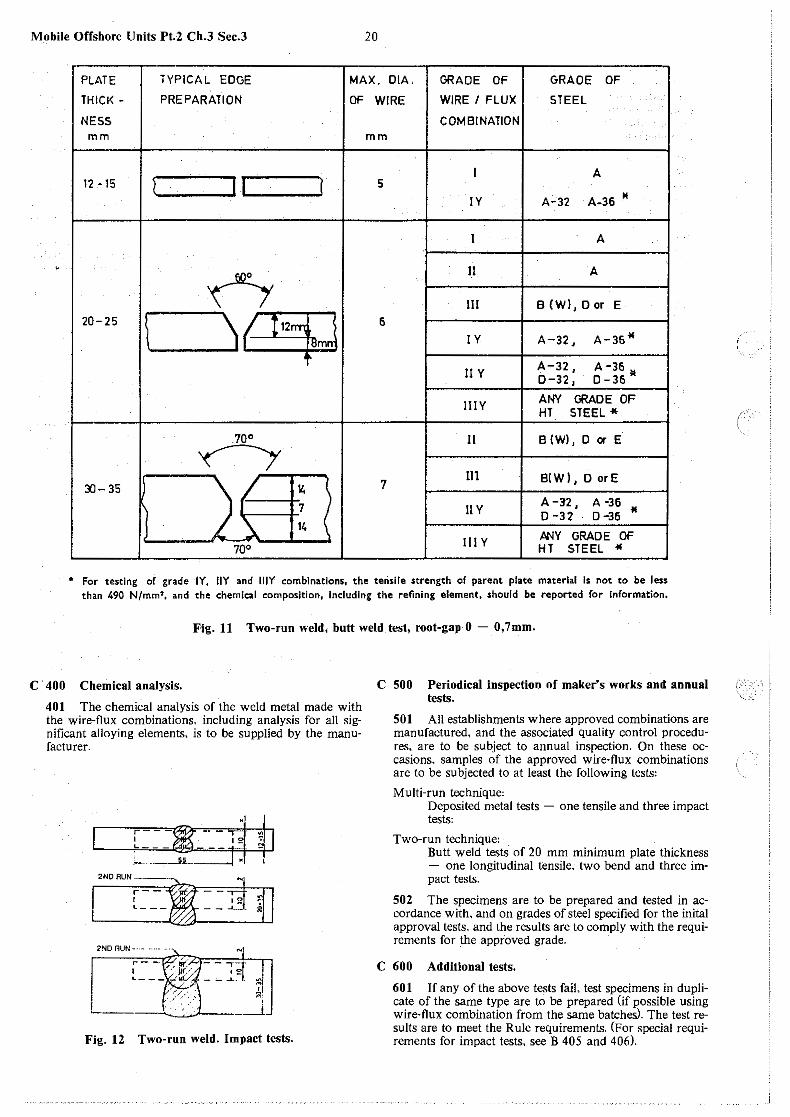
Mobile Offshore Units Pt.2 Ch.3 Sec.3 20
PLATE TYPICAL EDGE MAX. DIA. GRADE OF GRADE OF
THICK - PREPARATION OF WIRE WIRE I FLUX STEEL .
NESS COMBINATION mm mm
( 11 I A
12 -15 l 5
IV A-32 A-36 M
I A
' n n A
Ill B (W), 0 or E 20-25
1 \~ 6
IV A-32, A-36"
A-32, A-36 UY D-32, D-36 M
IllY ANY GRADE OF HT STEEL*
70° II B (W), D or E
<--y
)( 7 111 B!W), 0 orE
l'.l- 35 14 I
7 11 y A-l2, A -36
I D -32 D-36 " 14
/>NY GRADE OF . 70°
111 y HT STEEL "
• For testing of grade IY. llY and lllY combinations, the terislle strength of parent plate material is not to be less than 490 N/mm2 , and the chemical composition, Including the refining element, should be reported for Information.
F-ig. 11 Two-run weld, butt weld test, root-gap 0 - 0,7mm.
C · 400 Chemical analysis.
401 The chemical analysis of the weld metal made with the wire-flux combinations, including analysis for all significant alloying elements. is to be supplied by the manufacturer.
-1~
'.,-4 [ ~ I3 ;_ __ __s_i _____ !
2NDRUN- N I r-~--;; ~11
2NO RUN- .. - ·
r--~,~1--121 .: ~--~~~)- - Hd Z1
. ,:<: __J L -----
Fig. 12 Two-run weld. Impact tests.
C 500 Periodical inspection of maker's works and annual tests.
501 All establishments where approved combinations are manufactured, and the associated quality control procedures. are to be subject to annual inspection. On these occasions. samples of the approved wire-flux combinations are to be subjected to at least the following tests:
Multi-run technique: Deposited metal tests - one tensile and three impact tests:
Two-run technique: Butt weld tests of 20 mm minimum plate thickness - one longitudinal tensile. two bend and three impact tests.
502 The specimens are to be prepared and tested in accordance with, and on grades of steel specified for the inital approval tests, and the results are to comply with the requirements for the approved grade.
C 600 Additional tests.
601 If any of the above tests fail. test specimens in duplicate of the same type are to be prepared (if possible using wire-flux combination from the same batches). The test results are to meet the Rule requirements. (For special requirements for impact tests, see B 405 and 406).
(
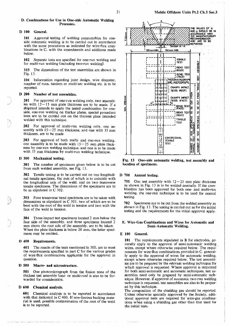
D. Combinations for Use in One-side Automatic Welding Processes.
D 100 General.
101 Approval testing of welding consumables for oneside automatic welding is to be carried out in accordance with the same procedures as indicated for wire-flux combinations in C, with the amendments and additions made below.
102 Separate tests are specified for one-run welding and for multi-run welding (including two-run welding).
103 The dimensions of the test assemblies are shown in Fig. 13.
104 Information regarding joint design. wire diameter, number of runs, tandem or multi-arc welding etc. is to be reported.
D 200 Number of test assemblies.
201 For approval of one-run welding only. two assemblies with 12- 15 mm plate thickness are to be made. If a shipyard intends to apply the tested combination for oneside, one-run welding on thicker plates, special procedure tests are to be carried out on the thickest plate intended welded with this technique.
202 For approval of multi-run welding only, one assembly with 15-25 mm thickness, and one with 35 mm thickness, are to be made.
203 For approval of both multi- and one-run welding. one assembly is to be made with 15-25 mm plate thickness by one-run welding technique, and one is to be made with 35· mm thickness by multi-run welding technique.
D 300 Mechanical testing.
301 The number of specimens given below is to be cut from each welded assembly, see Fig. 13.
302 Tensile testing is to be carried out on one longitudinal tensile specimen, the axis of which is to coincide with the longitudinal axis of the weld, and on two transverse tensile specimens. The dimensions of the specimens are to be as stipulated in C 302.
303 Four transverse bend specimens are to be taken with dimensions as stipulated in C 303. two of which are to be bent with the root of the weld in tension and two with the face of the weld in tension.
304 Three impact test specimens located 2 mm below the face side of the assembly, and three specimens located 2 mm above the root side of the assembly, are to be taken. When the plate thickness is below 20 mm, the latter specimens may be omitted.
D 400 Requirements.
401 The results of the tests mentioned In 300, are to meet the requirements specified in part C for the various grades of wire-flux combinations applicable for the approval in question.
D 500 Macro- and microstructure.
501 One photomicrograph from the fusion zone of the thickest test assembly (one- or multi-runl is also to be forwarded for consideration.
D 600 Chemical analysis.
601 Chemical analysis is to be reported in accordance with that indicated in C 400. If non-ferrous backing material is used, possible contamination of the root of the weld is to be reported.
21
~ ~ z
Mobile Offshore Units Pt.2 Ch.3 Sec.3
I o;:;;:;;'3L;.j. -..:-_-..;.,..:- :Jk<<<oZ<<::<::<JTHE VALUES OF« At.() g SHOULD BE IN ACCORO»CE. WITH THE MAN..IFACTURER's. RECa.t.1ENlltt.flON
I W//<jij;Y/./~'\.\,%'~~"'1~~POR~~ TO BE
r--- _I_-----, 1
1· I TENSILE
I lfEST ._ _____ , _____ .J
~-----r ----1BEND TEST L- -- __ ..,. --- __ 1 (ROOTI r---- -r -----,BEND TEST !.. ____ .:.. _____ :(FACE)
,.. i ,P!-IOTOMACROGR. ____ ~ • ...L_MD__:MICROGR.M'H_i
("' -1 I
._ - - - ~ } CHARPY IMPACT : ~ - ~ I ._ ::i.= ~ TESTS IOOOTJ [ _L J ~
~ ~ ~~ } CHARPY M'ACT ~ ._ -,.. -~ TESTS (FACE) ....
ALr- r: ~-L.JA a r---- ·~.:. ----,BENO TEST
?:;
; ~
m ·~ ,,;
~ ~
:>'· L_ ___ -~ ____ !(FACE) ~
a ~
f---- -=------lBENOTESTe J2 '------l ____ ... rROoTJ 111 111 ;--- -r ----1 TENSILE' ai Cfi
I I TEST ~> ~ L---- 4 ----J frla:i fi:j rr·' ih" Ill ' w
: • 1 Iii~ Iii Tt7 l!:! .... ~ 1 ·1 LONGITUDINAL u.I/) u. • I' TENSILE oj!:! o '·' TEST - "' 'j! a::· w H ~" "' ' . ' ~2: ::f'. 11 • ~z ~
J__ '"t.J ff. z
Fig. 13 One-side automatic welding, test assembly and location of specimens.
D 700 Annual testing.
701 One test assembly with 12-25 mm plate thickness as shown in Fig. 13 is to be welded annually. If the combination has been approved for both one- and multi-run welding, the one-run technique is to be used for annual testing.
702 Specimens are to be cut from the welded assembly as shown in Fig. 13. The testing is carried out as for the initial testing and the requirements for the initial approval apply.
E. Wire-Gas Combinations and Wires for Automatic and Semi-Automatic Welding.
E 100 General.
101 The requirements stipulated in B for electrodes, generally. apply to the approval of semi-automatic welding . wires, except where otherwise required below. The requirements for wire-flux combinations provided in C, generally apply to the approval of wires for automatic welding, except where otherwise required below. The test assemblies are to be prepared by the relevant welding technique for which approval is requested. Where approval is requested for both semi-automatic and automatic .techniques, test assemblies need only be prepared by semi-automatic technique. However, if approval of automatic two-run welding technique is requested, test assemblies are also to be prepared by this technique. The composition of the shielding gas should be reported. Unless otherwise specially approved by the Society. additional approval tests are required for wire-gas combinations when using a shielding gas other than that used for the initial tests.
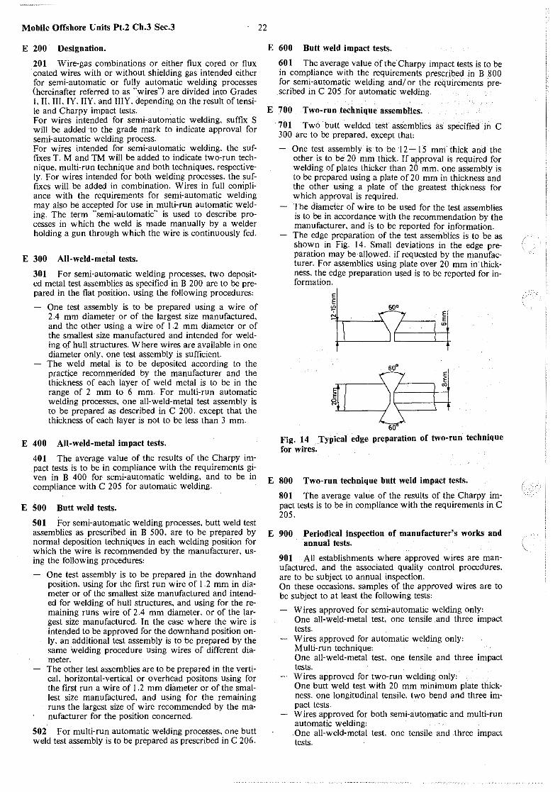
Mobile Offshore Units Pt.2 Ch.3 Sec.3
E 200 Designation.
201 Wire-gas combinations or either flux cored or flux coated wires with or without shielding gas intended either for semi-automatic or fully automatic welding processes (hereinafter referred to as "wires") are divided into Grades I. II. III. lY. IIY. and IIIY. depending on the result of tensi· le and Charpy impact tests. For wires intended for semi-automatic welding, suffix S will be added to the grade mark to indicate approval for semi-automatic welding process. For wires intended for semi-automatic welding. the suffixes T. M and TM will be added to indicate two·run technique. multi-run technique and both techniques. respectively. For wires intended for both welding processes, the suffixes will be added in combination. Wires in full corripliance with the requirements for semi-automatic welding may also be accepted for use in multi-run automatic welding. The term "semi-automatic" is used to describe processes in which the weld is made manually by a welder holding a gun through which the wire is continuously fed.
E 300 All-weld-metal tests.
301 For semi-automatic welding processes, two deposited metal test assemblies as specified in B 200 are to be prepared in the flat position, using the following procedures:
One test assembly is to be prepared using a wire of 2.4 mm diameter or of the largest size manufactured, and the other using a wire of I .2 mm diameter or of the smallest size manufactured and intended for welding of hull structures. Where wires are available in one diameter only, one test assembly is sufficient. The weld metal is to be deposited according to the practice recommerided by the manufacturer and the thickness of each layer of weld metal is to be in the range of 2 mm to 6 mm. For multi-run automatic welding processes. one all-weld-metal test assembly is to be prepared as described in C 200. except that the thickness of each layer is not to be less than 3 mm.
E 400 AU-weld-metal impact tes1s.
401 The average value of the results of the Charpy impact tests is to be in compliance with the requirements given in B 400 for semi-automatic welding. and to be in compliance with C 205 for automatic welding.
E 500 Butt weld tes1s.
501 For semi-automatic welding processes, butt weld test assemblies as prescribed in B 500, are to be prepared by normal deposition techniques in each welding position for which the wire is recommended by the manufacturer, using the following procedures:
One test assembly is to be prepared in the downhand position, using for the first run wire of l .2 mm in diameter or of the smallest size manufactured and intended for welding of hull structures. and using for the remaining runs wire of 2 .4 mm diameter, or of the largest size manufactured. In the case where the wire is intended to be approved for the downhand position only. an additional test assembly is to be prepared by the same welding procedure using wires of different diameter. The other test assemblies are to be prepared in the vertical, horizontal-vertical or overhead positons using for the first run a wire of 1 .2 mm diameter or of the smallest size manufactured, and using for the remaining runs the largest size of wire recommended by the manufacturer for the position concerned.
502 For multi-run automatic welding processes, one butt weld test assembly is to be prepared as prescribed in C 206.
22
E 600 Butt weld impact tests.
60 l The average value of the Charpy impact tests is to be in compliance with the requirements prescribed in B 800 for semi-automatic welding and/ or the requirements prescribed in C 205 for automatic welding.
E 700 Two-run technique assemblies.
701 Two butt welded test assemblies as specified in C 300 are to be prepared. except that'
One test assembly is to be 12- 15 mm thick and the other is to be 20 mm thick. If approval is required for welding of plates thicker than 20 mm. one assembly is to be prepared using a plate of 20 mm in thickness and the other using a plate of the greatest thickness for which approval is required. '1 'he diameter of wire to be used for the test assemblies is to be in accordance with the recommendation by the manufacturer. and is to be reported for information. The edge preparation of the test assemblies is to be as shown in Fig. 14. Small deviations in the edge preparation may be allowed. if requested by the manufacturer. For assemblies using plate over 20 mm in thickness, the edge preparation used is to be reported for information.
~
(I 60
El E w
El E ro
Fig. 14 Typical edge preparation of two-run technique for wires.
E 800 Two-run technique butt weld impact tests.
801 The average value of the results of the Charpy impact tests is to be in compliance with the requirements in C 205.
E 900 Periodical inspection of manufacturer's works and annual tests.
901 All establishments where approved wires are manufactured. and the associated quality control procedures, are to be subject to annual inspection. On these occasions, samples of the approved wires are to be subject to at least the following tests'
Wires approved for semi-automatic welding only: One all-weld-metal test, one tensile .and three impact tests. Wires approved for automatic welding only: Multi-run technique: One all-weld-metal test. one tensile and three impact tests. Wires approved for two-run welding only: One butt weld test with 20 mm minimum plate thickness. one longitudinal tensile, two bend and three impact tests. Wires approved for both semi-automatic and multi-run automatic welding: One all-weld-metal test one tensile and three impact tests.
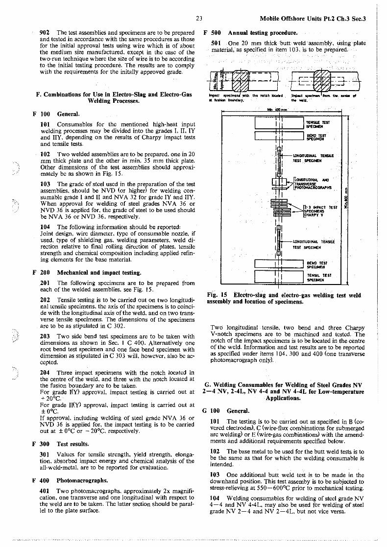
902 The test assemblies and specimens are to be prepared and tested in accordance with the same procedures as those for the initial approval tests using wire which is of about the medium size manufactured, except in the case of the two-run technique where the size of wire is to be according to the initial testing procedure. The results are to comply with the requirements for the initally approved grade.
F. Combinations for Use in Electro-Slag and Electro-Gas Welding Processes.
F 100 General.
101 Consumables for the mentioned high-heat input welding processes may be divided into the grades I. II. IY and IIY, depending on the results of Charpy impact tests and tensile tests.
102 Two welded assemblies are to be prepared, one in 20 mm thick plate and the other in min. 35 mm thick plate. Other dimensions of the test assemblies should approximately be as shown in Fig. 15.
103 The grade of steel used in the preparation of the test assemblies, should be NVD (or higher) for welding consumable grade I and II and NV A 3 2 for grade IY and IIY. When approval for welding of steel grades NV A 36 or NVD 36 is applied for, the grade of steel to be used should be NVA 36 or NVD 36, respectively.
104 The following information should be reported' Joint design, wire di~meter. type of consumable nozzle, if used, type of shielding gas, welding parameters, weld direction relative to final rolling direction of plates, tensile strength and chemical composition including applied refining elements for the base material.
F 200 Mechanical and impact testing.
201 The following specimens are to be prepared from each of the welded assemblies, see Fig. 15.
202 Tensile testing is to be carried out on two longitudinal tensile specimens, the axis of the specimens is to coincide with the longitudinal axis of the weld, and on two transverse tensile specimens. The dimensions of the specimens are to be as stipulated in C 302.
203 Two side bend test specimens are to be taken with dimensions as shown in Sec. 1 C 400. Alternatively one root bend test specimen and one face bend specimen with dimension as stipulated in C 303 will, however, also be accepted.
204 Three impact specimens with the notch located in the centre of the weld, and three with the notch located at the fusion boundary are to be taken. For grade I(Y) approval, impact testing is carried out at + 20°C. For grade II(Y) approval, impact testing is carried out at ± 0°C. If approval, including welding of steel grade NV A 36 or NVD 36 is applied for, the impact testing is to be carried out at ± 0°C or - 20°C, respectively.
F 300 Test results.
301 Values for tensile strength, yield strength, elongation, absorbed impact energy and chemical analysis of the all-weld-metal, are to be reported for evaluation.
F 400 Photomacrographs.
401 Two photomacrographs, approximately 2x magnification, one transverse and one longitudinal with respect to the weld are to be taken. The latter section should be parallel to the plate surface.
23 Mobile Offshore Units Pt.2 Ch.3 Sec.3
F 500 Annual testing procedure.
501 One 20 mm thick butt weld assembly, using plate material, as specified in item 103, is to be prepared.
H<....:L.:O..-[ti1f-· Jj tc-=-~3-· j """"""""'· ~to• """' '""'" .. ~ at fVshlon bollndary. tht Mid.
TENSl.E TEST
!===l=I:::==:::: SPECIMEN BENO TEST
~---<-+<'----~SPECIMEN
I _L~&ITUOINAl NC LI..L:....1"7j!IWISVERSE ~ l!'HOTOMACROOfW'HS
'
I
i4• :I IMPACT TE Sf SPECIMENS CHARPY V
I· 1llll , 111
I 1llll
LONGITUDINAL TENSILE TEST SPECllEN
BEND TEST Sf'ECIMEN
TENSIL TEST SPECl<EN
., §1 ~
Fig. 15 Electro-slag and electro-gas welding test weld assembly and location of specimens.
Two longitudinal tensile, two bend and three Charpy V-notch specimens are to be machined and tested. The notch of the impact specimens is to be located in the centre of the weld. Information and test results are to be reported as specified under items 104, 300 and 400 fone transverse photomacrograph only).
G. Welding Consumables for Welding of Steel Grades NV 2-4 NV, 2-4L, NV 4-4 and NV 4-4L for Low-temperature
Applications.
G 100 General.
101 The testing is to be carried out as specified in B (covered electrodes), C (wire-flux combinations for submerged arc welding) or E (wire-gas combinations) with the amendments and additional requirements specified below.
102 The base metal to be used for the butt weld tests is to be the same as that for which the welding consumable is intended.
103 One additional butt weld test is to be made in the downhand position. This test assemby is to be subjected to stress-relieving at 550-600°C prior to mechanical testing.
104 Welding consumables for welding of steel grade NV 4-4 and NV 4-4L, may also be used for welding of steel grade NV 2-4 and NV 2-4L, but not vice versa.
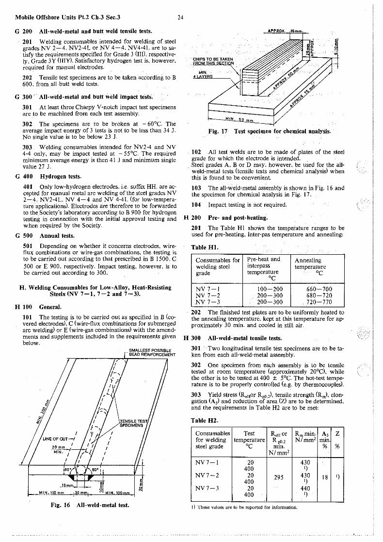
Mobile Offshore Units Pt.2 Ch.3 Sec.3
G 200 All-weld-metal and butt weld tensile tests.
201 Welding consumables intended for welding of steel grades NV 2-4, NV2-4L or NV 4-4, NV4-4L are to satisfy the requirements specified for Grade 3 (III), respectively, Grade 3Y Ol!Y). Satisfactory hydrogen test is. however. required for manual electrodes.
202 Tensile test specimens are to be taken according to B 600. from all butt weld tests.
G 300 All-weld-metal and butt weld impact tests.
301 At least three Charpy V-notch impact test specimens are to be machined from each test assembly.
302 The specimens are to be broken at - 60°C. The average impact energy of 3 tests is not to be less than 34 J. No single value is to be below 23 J.
303 Welding consumables intended for NV2-4 and NV 4-4 only, may be impact tested at - 55°C. The required minimum average energy is then 41 J and minimum single value 27 J.
G 400 Hydrogen tests.
401 Only low-hydrogen electrodes. i.e. suffix HH. are accepted for manual metal arc welding of the steel grades NV 2-4, NV2-4L, NV 4-4 and NV 4-4L (for low-temperature applications). Electrodes are therefore to be forwarded to the Society's laboratory according to B 900 for hydrogen testing in connection with the initial approval testing and when required by the Society.
G 500 Annual tests.
501 Depending on whether it concerns electrodes, wiretlux combinations or wire-gas combinations, the testing is to be carried out according to that prescribed in B 1500. C 500 or E 900, respectively. Impact testing, however, is to be carried out according to 300.
H. Welding Consumables for Low-Alloy, Heat-Resisting Steels (NV 7-1, 7-2 and 7-3).
H 100 General.
101 The testing is to be carried out as specified in B (covered electrodes), C (wire-flux combinations for submerged arc welding) or E (wire-gas combinations) with the amendments and supplements included in the requirements given below.
'E: E
0
SMALLEST POSSIBLE BEAD REINFORCEMENT
~I I MIN.100mm 130!!!1!4 -1 MIN...J.Q.Q.mm "
Fig. 16 All-weld-metal test.
24
~ CHIPSTOBETAKENN. ~,.&'.
I "'I~ ,.4 EBQMTHISSECT!O ~~/
MIN. ""r ti.6Y&B§.
i
I~
_MIH . .s.o mm
Fig. 17 Test specimen for chemical analysis.
102 All test welds are to be made of plates of the steel grade for which the electrode is intended. Steel grades A, B or D may, however, be used for the allweld-metal tests (tensile tests and chemical analysisl when this is found to be convenient.
103 The all-weld-metal assembly is shown in Fig. 16 and the specimen for chemical analysis in Fig. 17.
104 Impact testing is not required.
H 200 Pre- and post-heating.
201 The Table HI shows the temperature ranges to be used for pre-heating, inter-pas temperature and annealing:
Table Hl.
Consumables for Pre-heat and Annealing welding steel interpass temperature grade temperature oc oc NV7-l 100-200 660-700 NV7-2 200-300 680-720 NV7-3 200-300 720-770
202 The finished test plates are to be uniformly heated to the annealing temperature, kept at this temperature for approximately 30 min. and cooled in still air.
H 300 Aii-weid-metai tensile tests.
301 Two longitudinal tensile test specimens are to be taken from each all-weld-metal assembly.
302 One specimen from each assembly is to be tensile tested at room temperature (approximately 20°C), while the other is to be tested at 400 ± 5°C. The hot-test temperature is to be properly controlled (e.g. by thermocouples).
303 Yield stress (R,8 or R,0,2), tensile strength (R,,,), elongation (A5) and reduction of area (Z) are to be determined, and the requirements in Table H2 are to be met:
Table H2.
Consumables Test ReHor Rm min. As z for welding temperature R ,,0.2 N/mm2 min. steel grade oc min. % %
N/mm2
NV7-l 20 430 400 1)
NV7-2 20 295 430 18 1) 400 1)
NV7-3 20 440 400 1)
I) These values are to be reported for information.
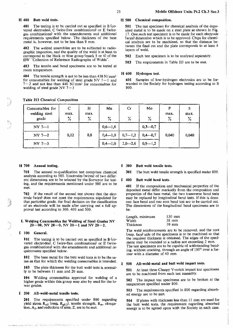
H 400 Butt weld tests.
401 The testing is to be carried out as specified in B (covered electrodes), C (wire-flux combinations) or E (wiregas combinations) with the amendements and additional requirements specified below. The thickness of the base metal is, however, not to be less than 9 mm.
402 The welded assemblies are to be subjected to radiographic inspection. and the quality of the weld is at least to correspond to the black or blue group (mark 5 or 4) of the IIW "Collection of Reference Radiographs of Welds"".
403 The tensile and bend specimens are to be tested at room temperature.
404 The tensile strength is not to be less than 430 N/mm' for consumables for welding of steel grade NV 7 - I and 7 - 2 and not less than 440 NI mm' for consumables for welding of steel grade NV 7 - 3
Table H3 Chemical Composition
Consumables for c Si Mn welding steel max. max.
grade % % %
NV 7-1 0,6-1,6
NV 7-2 0,12 0,8 0,4-1,0
NV 7-3 !
0,4-1,0
H 700 Annual testing.
701 The annual re-qualification test comprises chemical analysis according to 500. Electrodes (wires) of two different dimensions are to be selected by the Surveyor for testing, and the requirements mentioned under 500 are to be met.
702 If the result of the annual test shows that the electrode ( wirel does not meet the requirements stipulated for that particular grade, the final decision on the classification of an electrode will be made after carrying out a full approval test according to 300, 400 and 500.
I. Welding Consumables for Welding of Steel Grades NV 20-00, NV 20-0, NV 20-1 and NV 20-2.
I 100 General.
101 The testing is to be carried out as specified in B (covered electrodes), C (wire-flux combinatious) or E (wiregas combinations) with the amendments and additional requirements specified below.
102 The base metal for the butt weld tests is to be the same as that for which the welding consumables is intended.
103 The plate thickness for the butt weld tests is normally to be between 11 mm and 20 mm.
104 Welding consumables approved for welding of a higher grade within this group may also by used for the lower grades.
I 200 All-weld-metal. tensile tests.
201 The requirements specified under 800 regarding yield stress R,8 (resll- Rp0.2J, tensile strength, Rm, elongation, A,. and reduction of area, Z, are to be met.
25 Mobile Offshore Units Pt.2 Ch.3 Sec.3
H 500 Chemical composition.
501 The test specimen for chemical analysis of the deposited metal is to be made on a steel plate as shown in Fig. 17. One .such test specimen is to be made for each electrode (wire) dimension which is to be approved. Chips for chemical analysis are to be machined, so that the distance between the final cut and the plate corresponds to at least 4 layers of weld.
502 Each test specimen is to be analysed separately.
503 The requirements in Table HJ are to be met.
H 600 Hydrogen test.
601 Samples of low-hydrogen electrodes are to be forwarded to the Society for hydrogen testing according to B 900.
Cr Mo p s max. max.
% % % %
0,3--0,7
0,7-1,2 0,4--0,7 0,040 0,040
2,0-2,6 0,9-1,2
I 300 Butt weld tensile tests.
301 The butt weld tensile strength is specified under 800.
I 400 Butt weld bend tests.
401 If the composition and mechanical properties of the deposited metal differ markedly from the composition and properties of the base metal, the two transverse bend tests may be replaced by longitudinal bend tests. If this is done, one face bend and one root bend test are to be carried out. The dimensions of the longitudinal bend specimens are to be'
Length, minimum Width Thickness
150 mm 38 mm IO mm
The weld reinforcements are to be removed, and the root (resp. face) side of the specimens is to be machined so that the required thickness is obtained. The edges of the specimens may be rounded to a radius not exceeding 2 mm. The test specimens are to be capable of withstanding bending, without cracking, through an angle of 180° over a former with a diameter of 40 mm.
I 500 All-weld-metal and butt weld impact tests.
501 At least three Charpy V-notch impact test specimens are to be machined from each test assembly.
502 The impact test specimens are to be broken at the temperature specified under 800.
503 The requirements specified in 800 regarding absorbed energy are to be met.
504 If plates with thickness less than 11 mm are used for the butt weld tests, the requirement regarding absorbed energy is to be agreed upon with the Society in each case.
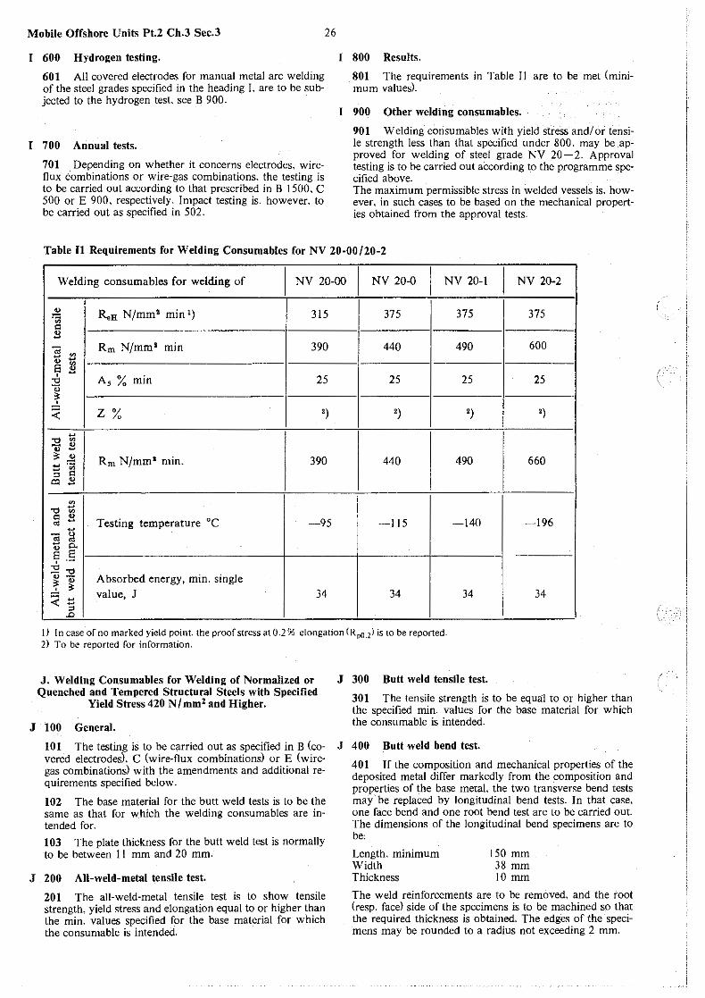
Mobile Offshore Units Pt.2 Ch.3 Sec.3
I 600 Hydrogen testing.
601 All covered electrodes for manual metal arc welding of the steel grades specified in the heading I. are to be subjected to the hydrogen test. see B 900.
I 700 Annual tests.
701 Depending on whether it concerns electrodes, wireflux combinations or wire-gas combinations. the testing is to be carried out according to that prescribed in B 1500. C 500 or E 900. respectively. Impact testing is. however. to be carried out as specified in 502.
26
I 800 Results.
801 The requirements in Table I 1 are to be met (minimum values).
I 900 Other welding consumables.
901 Welding consumables with yield stress and/or tensile strength less than that specified under 800. may be approved for welding of steel grade NV 20-2. Approval testing is to be carried out according to the programme specified above. The maximum permissible stress in welded vessels is. however, in such cases to be based on the mechanical properties obtained from the approval tests.
Table Il Requirements for Welding Consumables for NV 20-00/20-2
Welding consumables for welding of I
NV 20-00 I
NV 20-0 I
NV 20-1 I NV 20-2
" R.H N/mm 2 min 1) 315 375 375 375 ~ c B -;; ~ Rm N/mm' min 390 440 490 600 ~ t; e " ' - A 5 % min 25 25 25 25 ""' OJ
" ...!. :;;: z % ') ') ') ')
-I
""' ~ - " " -" .£ Rm N/mm' min. 390 440 490 660 -·--~
I " c o:l B
~
""' ~ " " Testing temperature °C -95 ·-140 ---196 "' - -115 --;; ~ - 0. a e ' ·-
:'2 ""' Absorbed energy, min. single " -l ~ < !:: value, J 34 34 34 34
" .D
I) In case of no marked yield point. the proof stress at 0.2 % elongation (Rp(}.l) is to be reported. 2) To be reported for information.
J. Welding Consumables for Welding of Normalized or Quenched and Tempered Structural Steels with Specified
Yield Stress 420 N /mm 2 and Higher.
J 100 General.
101 The testing is to be carried out as specified in B (covered electrodes), C (wire· flux combinations) or E (wiregas combinations) with the amendments and additional requirements specified below.
102 The base material for the butt weld tests is to be the same as that for which the welding consumables are intended for.
103 The plate thickness for the butt weld test is normally to be between 11 mm and 20 mm.
J 200 All-weld-metal tensile test.
201 The all-weld-metal tensile test is to show tensile strength. yield stress and elongation equal to or higher than the min. values specified for the base material for which the consumable is intended.
J 300 Butt weld tensile test.
301 The tensile strength is to be equal to or higher than the specified min. values for the base material for which the consumable is intended.
J 400 Butt weld bend test.
401 If the composition and mechanical properties of the deposited metal differ markedly from the composition and properties of the base metal. the two transverse bend tests may be replaced by longitudinal bend tests. In that case. one face bend and one root bend test are to be carried out. The dimensions of the longitudinal bend specimens are to beo
Length. minimum Width Thickness
150 mm 38 mm IO mm
The weld reinforcements are to be rerrioved, and the root (resp. face) side of the specimens is to be machined so that the required thickness is obtained. The edges of the specimens may be rounded to a radius not exceeding 2 mm.

~,\
27
The test specimens are to be bent through an angle of 120° over a former with diameter three times the thickness of the specimen. The test is considered as passed if, after bending, no cracks or other open defects exceeding 3 mm in dimension can be seen on the outer surface. Other acceptance criteria may be considered for materials with higher tensile strength and yield stress.
J 500 All-weld-metal and butt weld impact test.
501 At least three Charpy V-notch test specimens are to be cut from each assembly.
502 The impact test specimens are to be broken at - 20°C. - 40°C or - 60°C. The approval will be valid only for welding of steel with specified impact test temperature equal to or warmer than the test temperature applied for testing of the consumables.
503 Absorbed impact energy is to be min. 40 J in average of three specimens and no single value is to be lower than 27 J.
Mobile Offshore Units Pt.2 Ch.3 Sec.3
J 600 Hydrogen testing.
601 All covered electrodes for manual metal arc welding and all flux cored wires are to be subjected to the hydrogen test. see B 900. The hydrogen content for these electrodes shall be less or equal to 5 cm per I 00 grammes weld metal measured by the glycerine method.
J 700 Chemical analysis.
701 The chemical analysis of the weld made by the consumables, including analysis for all significant alloying elements, is to be supplied by the manufacturer.
J 800 Annual tests.
801 Depending on whether it concerns electrodes, wireflux combinations or wire-gas combinations, the testing is to be carried out according to B 1500, C 500 or E 900, respectively. Impact testing is, however, to be carried out as specified in 502.
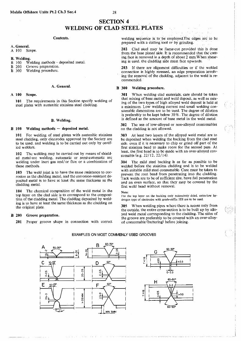
Mobile Offshore Units Pt.2 Ch.3 Sec.4 28
SECTION 4 WELDING OF CLAD STEEL PLATES
Contents.
A. General. A 100 Scope.
B. Welding. B 1 00 Welding methods - deposited metal. B 200 Groove preparation. B 300 Welding procedure.
A. General.
A 100 Scope.
101 The requirements in this Section specify welding of steel plates with austenitic stainless steel cladding.
B. Welding.
B 100 Welding methods - deposited metal.
101 For welding of steel plates with austenitic stainless steel cladding, only electrodes approved by the Society are to be used, and welding is to be carried out only by certified welders.
102 The welding may be carried out by means of shielded metal-arc welding, automatic or semi-automatic arc welding under inert gas and/ or flux or a combination of these methods.
103 The weld joint is to -have the same resistance to corrosion as the cladding metal, and the corrosion-resistant deposited metal is to have at least the same thickness as the cladding metal.
104 The chemical composition of the weld metal in the top layer on the clad side is to correspond to the composition of the cladding metal. The cladding deposited by welding is to have at least the same thickness as the cladding on the original plate.
B 200 Groove preparation.
201 Proper groove shape in connection with correct
welding sequence is to be employed.The edges are to be prepared with a cutting tool or by grinding.
202 Clad steel may be flame-cut provided this is done from the base plated side. It is recommended that the cutting face is removed in a depth of about 2 mm.When shearing is used, the cladding side must face upwards.
203 If there are alignment difficulties or if the welded connection is highly stressed, an edge preparation involving the removal of the cladding, adjacent to the weld is recommended.
B 300 Welding procedure.
301 When welding clad materials. care should be taken that mixing of base metal and weld deposit. as well as mixing of the two types of high alloyed weld deposit is held at a minimum. Low welding current and small welding consumable dimensions are to be used. The degree of dilution is preferably to be kept below 30 % . The degree of dilution is defined as the amount of base metal in the weld metal.
302 The use of low-alloyed or non-alloyed consumables on the cladding is not allowed.
303 At least two layers of the alloyed weld metal are to be deposited when welding the backing from the clad steel side, even if it is necessary to chip or grind off part of the first stainless bead to make room for the second pass. At least, the first bead is to be made with an over-alloyed consumable (e.g. 22/12, 22/14).
304 The mild steel backing is as far as possible to be welded before the stainless cladding and is to be welded with suitable mild steel consumable. Care must be taken to prevent the root bead from penetrating into the cladding. Tack welds are to be of sufficient size, have full penetration and an even surface, so that they may be covered by the first weld bead without removal.
Note: For the top layer on the backing only extensively dried, extra-low hydrogen type of electrodes with grade-suffix HH are to be used.
305 When welding pipes where there is access only from the outside, the entire cross-section is to be built up by alloyed weld metal corresponding to the cladding. The sides of the groove are preferably to be covered with an over-alloyed consumable (buttering) before joining.
EXAMPLES ON MOST COMMENLY USED GROOVES
A"' ao-9
oo 9 so-100
i ~t 2 :1i ~[i ?;;....,..~~Ii G 60-900
C 10-"0 ~~ • [I
~LJ I~ ~ ~ ! ~1 \L..l>2.0
I 1 .; I N I
' .,.. : ! : ' I ' ! ! '~•"
('' '.·. i
i
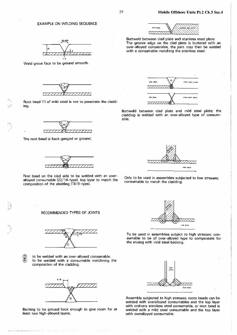
EXAMPLE ON WELDING SEQUENCE
~
06±~21 I/-///
1-3
Weld grove face to be ground smooth.
; I I/ I/~//// 7 7 c
Root bead I 1) of mild steel is not to penetrate the cladding.
~ ZZZ/c / 2 / 7 / / _:l 7 7 /
The root bead is back-gauged or ground.
J//11/~//1/1//, First bead on the clad side to be welded with an overalloyed consumable (22/ 14-type), top layer to match the composition of the cladding (18/8-type).
~
RECOMMENDED TYPES OF JOINTS
,!@\,
to be welded with an over-alloyed consumable. to be welded with a consumable matchning the composition of the cladding.
4-0[] '///// "© 6r,
. (
'© '
Backing to be ground back enough to give room for at least two high-alloyed layers_
29 Mobile Offshore Units Pt.2 Ch.3 Sec.4
""'""'~ >\.'\\."" '"'
s1o"11ess Slool plo1•
0: Buttweld between clad plate and stainless steel plate: The groove edge on the clad plate is buttered with an over-alloyed consumable, the joint may then be welded with a consumable matching the stainless steel.
clod pliile \©/ m•ld oioel plolo
<lodpl<>t• mild >IHI plate
Buttweld between clad plate and mild steel plate; the cladding is welded with an over-alloyed type of consumable_
72//2$9§'/24'9'/?2//Z clod plole
Only to be used in assemblies subjected to low stresses; consumable to match the cladding_
/1 'it~~";;.~·
.~<>,if ,,
dad plolo
To be used in assemblies subject to high stresses: consumable to be of over-alloyed type to compensate for the mixing with mild steel backing.
clad ·plate
clad plate
Assembly subjected to high stresses; roots beads can be welded with overalloyed consumables and the top layer with ordinary stainless steel consumable, or root bead is welded with a mild steel consumable and the top layer with overalloyed consumable_


![One platform Multiple options...GOST Butt weld DIN Butt weld ANSI Butt weld Socket weld Female 1 pipe thread F-con. ) butt weld GOST Butt weld [mm] [in.] D A SOC FTP F G D A SOC FTP](https://img.pdfslide.us/doc/110x75/5fe23d7adfe1ef18be65fa23/one-platform-multiple-options-gost-butt-weld-din-butt-weld-ansi-butt-weld-socket.jpg)