Embed Size (px)
Citation preview

Online Technical Support:support.mobilelinkgen.com
MobileLink:mobilelinkgen.com
855-436-8439—United States844-843-9436—Canada
SAVE THIS MANUAL FOR FUTURE REFERENCE
Mobile Link™Wi-Fi ® Remote Monitoring
Installation and User Manual
(000209b)
WARNINGLoss of life. This product is not intended to be used in a critical life support application. Failure to adhere to this warning could result in death or serious injury.

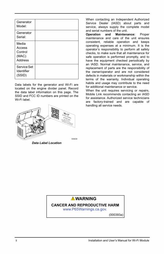
Data labels for the generator and Wi-Fi arelocated on the engine divider panel. Recordthe data label information on this page. TheSSID and FCC ID numbers are printed on theWi-Fi label.
Data Label Location
When contacting an Independent AuthorizedService Dealer (IASD) about parts andservice, always supply the complete modeland serial numbers of the unit.Operation and Maintenance: Propermaintenance and care of the unit ensuresconsistent, reliable operation and keepsoperating expenses at a minimum. It is theoperator’s responsibility to perform all safetychecks, to make sure that all maintenance forsafe operation is performed promptly, and tohave the equipment checked periodically byan IASD. Normal maintenance, service, andreplacement of parts are the responsibility ofthe owner/operator and are not considereddefects in materials or workmanship within theterms of the warranty. Individual operatinghabits and usage may contribute to the needfor additional maintenance or service.When the unit requires servicing or repairs,Mobile Link recommends contacting an IASDfor assistance. Authorized service techniciansare factory-trained and are capable ofhandling all service needs.
Generator Model:
Generator Serial:
Media Access Control (MAC) Address
Service Set Identifier (SSID)
004434
[STA MAC ADDRESS][AP MODE SSID]
http://192.168.51.1
CONTAINS FCC ID: YOPGS2101M
CONTAINS IC: 9154A-GS2101M
ii Installation and User’s Manual for Wi-Fi Module
(000393a)
WARNINGCANCER AND REPRODUCTIVE HARM
www.P65Warnings.ca.gov.

Section 1: SafetyIntroduction ................................................................................................. 4General Safety............................................................................................. 4General Safety Hazards.............................................................................. 4Electrical Hazards ....................................................................................... 5Explosion Hazards...................................................................................... 5
Section 2: General Information and SetupIntroduction ................................................................................................. 6Glossary....................................................................................................... 6Description .................................................................................................. 6Wi-Fi Network Usage .................................................................................. 6Wi-Fi Network Infrastructure Limitations ................................................. 6Wi-Fi Network Signal Strength .................................................................. 7Firmware Updates....................................................................................... 7Wi-Fi Specifications.................................................................................... 7
Section 3: Setup and OperationPre-Installation Signal Strength Test ........................................................ 8
Connect to Home Network ....................................................................................... 8Wi-Fi Setup at Generator Controller.......................................................... 9
Connect to Home Network When Internet is Available on the Mobile Device .......... 9Connect to Home Network When Internet is NOT Available on the Mobile Device 13Retry Network Connection ...................................................................................... 16Reconnection .......................................................................................................... 16Wi-Fi Menu Map ..................................................................................................... 17
Download Mobile Link and Complete Registration ............................... 18Disable Wi-Fi ............................................................................................. 18Reset Wi-Fi to Factory Default Settings.................................................. 18
Section 4: TroubleshootingGeneral Troubleshooting ......................................................................... 19IASD Troubleshooting .............................................................................. 19
Section 5: Terms and Acronyms
Installation and User’s Manual for Wi-Fi Module iii
Table of Contents

Safety
Section 1: Safety
Introduction
Read This Manual Thoroughly
The information in this manual is accuratebased on products produced at the time ofpublication. The manufacturer reserves theright to make technical updates, corrections,and product revisions at any time withoutnotice.
If any section of this manual is not understood,contact the nearest Independent AuthorizedService Dealer (IASD) for starting, operating,and servicing procedures.
SAVE THESE INSTRUCTIONS: Themanufacturer requires that this manual andthe rules for safe operation be copied andposted near the unit’s installation site. Safetyshould be stressed to all operators andpotential operators of this equipment.
SAFETY: Throughout this manual, DANGER,WARNING, CAUTION and NOTE blocks areused to alert personnel about particularoperations, functions or services that may behazardous if performed incorrectly orcarelessly. Their definitions are as follows:
NOTE: Notes provide additional informationimportant to a procedure or component.
These safety alerts cannot eliminate thehazards that they signal. Strict compliancewith these special instructions, plus commonsense, are major accident preventionmeasures.
General Safety
The manufacturer cannot anticipate everypossible circumstance that might involve ahazard. The safety messages in this manualand on tags and decals affixed to the unit are,therefore, not all-inclusive. If using aprocedure, work method or operatingtechnique the manufacturer does notspecifically recommend, verify that it is safefor personnel. Also make sure the procedure,work method or operating technique utilizeddoes not render the generator unsafe.
General Safety Hazards
• For safety reasons, the manufacturerrequires this equipment be installed by anIndependent Authorized Service Dealer(IASD) or other competent, qualifiedelectrician or installation technician who isfamiliar with applicable codes, standards
(000001)
DANGERIndicates a hazardous situation which, if not avoided, will result in death or serious injury.
(000002)
WARNINGIndicates a hazardous situation which, if not avoided,could result in death or serious injury.
(000003)
CAUTIONIndicates a hazardous situation which, if not avoided,could result in minor or moderate injury.
(000100a)
WARNINGConsult Manual. Read and understand manualcompletely before using product. Failure to completely understand manual and productcould result in death or serious injury.
(000129)
DANGERElectrocution. High voltage is present at transfer switch and terminals. Contact with live terminals will result in death or serious injury.
(000130)
WARNINGAccidental Start-up. Disconnect the negative battery cable, then the positive battery cable when working on unit. Failure to do so could result in death or serious injury.
WARNINGRisk of injury. Do not operate or service this machine if not fully alert. Fatigue can impair the ability to service this equipment and could result in death or serious injury.
(000215)
(000130)
WARNINGAccidental Start-up. Disconnect the negative battery cable, then the positive battery cable when working on unit. Failure to do so could result in death or serious injury.
WARNINGInjury and equipment damage. Do not use generator as a step. Doing so could result in falling, damaged parts, unsafe equipment operation, and could result in death or serious injury.
(000216)
4 Installation and User’s Manual for Wi-Fi Module

Safety
and regulations. The operator also mustcomply with all such codes, standards andregulations.
NOTE: Follow the shutdown proceduredescribed in the generator owner’s manualbefore performing any work on or near thegenerator.
Remove the control panel fuse and disconnectthe black (–) battery cable to preventaccidental startup. When disconnectingbattery cables, always remove the black (–)cable first, then remove the red (+) cable.When reconnecting the cables, connect thered (+) cable first, and then black (–) cable.
Electrical Hazards
The generator may crank and start at any timewhen utility is lost. When this occurs, loadcircuits are transferred to the STANDBY(generator) power source. Before working onthis generator (for inspection, service ormaintenance), to prevent possible injury,always set the generator to the OFF modeand remove the 7.5A fuse from the generatorcontrol panel.
• Verify all appropriate covers, guards andbarriers are in place, secured and/or lockedbefore operating the generator. If workmust be done around an operating unit,stand on an insulated, dry surface toreduce potential shock hazard.
Explosion Hazards
• Verify no combustible materials are left inthe generator compartment or on or nearthe generator as FIRE or EXPLOSION mayresult. Keep the area surrounding thegenerator clean and free from debris.
• Fuels, such as natural gas and liquidpropane (LP) gas, are extremelyEXPLOSIVE. Install the fuel supply systemaccording to applicable fuel-gas codes.Before placing the home standby electricsystem into service, fuel system lines mustbe properly purged and leak testedaccording to applicable code. Inspect thefuel system periodically for leaks. Noleakage can be permitted.
(000187)
WARNINGElectrocution. Potentially lethal voltages are generatedby this equipment. Render the equipment safe beforeattempting repairs or maintenance. Failure to do socould result in death or serious injury.
(000144)
DANGERElectrocution. Contact with bare wires, terminals, and connections while generator is running will result in death or serious injury.
(000188)
DANGERElectrocution. Do not wear jewelry while working on this equipment. Doing so will result in death or serious injury.
(000104)
DANGERElectrocution. Water contact with a power source, if not avoided, will result in death or serious injury.
Automatic start-up. Disconnect utility power and render unit inoperable before working on unit. Failure to do so will result in death or serious injury.
(000191)
DANGER
(000145)
DANGERElectrocution. In the event of electrical accident, immediately shut power OFF. Use non-conductive implements to free victim from live conductor. Apply first aid and get medical help. Failure to do so will result in death or serious injury.
(000115)
WARNINGMoving Parts. Do not wear jewelry when starting or operating this product. Wearing jewelry while starting or operating this product could result in death or serious injury.
(000192)
DANGERExplosion and fire. Fuel and vapors are extremelyflammable and explosive. No leakage of fuel ispermitted. Keep fire and spark away. Failure to doso will result in death or serious injury.
(000143)
DANGERExplosion and Fire. Fuel and vapors are extremely flammable and explosive. Store fuel in a well ventilated area. Keep fire and spark away. Failure to do so will result in death or serious injury.
WARNINGExplosion and fire risk. Do not smoke near unit. Keep fire and spark away. Failure to do so could result in death, serious injury, or property or equipment damage. (000282)
Installation and User’s Manual for Wi-Fi Module 5

General Information and Setup
Section 2: General Information and Setup
IntroductionThis section of the manual describes thefeatures and controls of the Wi-Fi® moduleand system. Every effort was made to verifythe information and instructions in thismanual were both accurate and current at thetime the manual was written. However, themanufacturer reserves the right to change,alter or otherwise improve this product ormanual at any time without prior notice.
NOTE: Wi-Fi® is a registered trademark ofWi-Fi Alliance®.
GlossaryThe back of this manual contains a glossaryof Terms and Acronyms associated withWi-Fi enabled modules and controllers.
DescriptionThe Wi-Fi module is mounted on the back ofthe generator and communicates with thegenerator’s controller through a wiringharness. Generator status and operatinginformation is periodically transmitted overthe generator owner’s private Wi-Fi network.This enables the generator owner to monitorgenerator status from anywhere he or shehas Internet access. Controller updates areautomatically downloaded and installed fromMobile Link’s file server.
Automatic standby generators requireactivation in order to operate automatically.This one-time process also serves as theproduct registration. For activation instructions,refer to the Installation Manual provided withthe unit.
The owner may also choose to set up anoptional account on www.mobilelinkgen.com.An active Mobile Link™ subscription enablesthe owner to log onto the website to check onthe current status of the generator at anytime. This also enables the system to notifythe owner of any change in operating status.With a valid subscription, the owner can becontacted by e-mail, push notifications, ortext messages if alarms or warnings occur.The delivery method and frequency of somealerts can be adjusted on the website andmobile app.
Wi-Fi Network UsageThe installed and activated Wi-Fi modulemaintains a connection to the private Wi-Finetwork. Operating data, including certaincustomer information, will be shared betweenthe generator and Mobile Link. By using MobileLink, you agree to collection and use of thisdata subject to Mobile Link’s privacy policylocated at https://www.mobilelinkgen.com/PrivacyStatement.aspx.
While every effort has been made to protectuser data, all networks are susceptible toexternal attacks. Mobile Link cannotguarantee absolute security as a result.Mobile Link is not aware of or responsible forthe level of network security provided by thenetwork owner. Also, Mobile Link accepts noliability for external attacks.
IMPORTANT NOTE: As with any Wi-Fidevice, it is imperative to take all necessarymeasures to secure the connection andavoid security breaches and theft ofpersonal data. Such security measures arethe customer’s responsibility.
Operating data transmitted over the Wi-Finetwork may be counted towards monthlyInternet service plan limits. The Wi-Finetwork owner is responsible for monitoringdata usage after the Wi-Fi module is installedand activated.
Wi-Fi Network Infrastructure LimitationsAll communication systems have benefitsand limitations based on consistency, cost,number of nodes, and additional factors.Consistent Wi-Fi communication will varydepending on the reliability and responsetime of your Internet Service Provider (ISP)under normal operating conditions and duringa storm or utility outage. In addition, the typeof network equipment you own, and the wayit is configured, can also affect thegenerator’s ability to communicate via MobileLink Wi-Fi.
As an alternative, Mobile Link Cellular communication is available as an accessory. Contact your IASD, or visit www.mobilelinkgen.com for more information.
NOTE: Installing Mobile Link Cellular requiresdisabling Wi-Fi.
6 Installation and User’s Manual for Wi-Fi Module

General Information and Setup
Wi-Fi Network Signal StrengthIf the home Wi-Fi signal strength isinsufficient for communicating with thegenerator, a wireless repeater (signalbooster) can be installed in the home.Wireless repeaters may be purchased fromany local computer or electronics retailer.
Firmware UpdatesOccasional updates may be released for thegenerator controller operating system(firmware). Once installed and activated, theWi-Fi module enables automatic reception offirmware updates as sent directly from themanufacturer.
Wi-Fi Specifications
Specification Value
Networking standard
IEEE 802.11.b/g/n
Transceiver RS485
Module operating power
5 VDC
Cable RS485
Supply voltage
(V+ to GND)
Nominal: 5 VDC
Minimum: 4.3 VDC
Maximum: 6.2 VDC
RS-485 charge spike rejection (either A or B); line idle
Minimum 1.5 nC
UL Listing Number FTPM/E359637
FCC ID
(See engine divider panel for label location)
YOPGS2101M
IC Certification 9154A-GS2101M
CE R1603222
Telec 211-160302
Installation and User’s Manual for Wi-Fi Module 7

Setup and Operation
Section 3: Setup and Operation
The Wi-Fi module is provided as standardequipment.
Before the generator is delivered to theinstallation site, perform the Pre-InstallationSignal Strength Test to determine if theexisting Wi-Fi signal is sufficient for use or if itmust be boosted.
Pre-Installation Signal Strength Test NOTE: Most network routers automaticallybroadcast their Wi-Fi network name every fewseconds. Network owners may choose todisable broadcasting, making the homenetwork invisible.
1. See Figure 3-1. Position a mobile device inthe proposed generator installation location.
Figure 3-1. Test Wi-Fi Signal Strength
2. Set up a mobile device (smartphone,tablet, or laptop) to detect Wi-Fi networks.
3. See Figure 3-2. Verify the home Wi-Finetwork is being detected by the mobiledevice. Observe the Wi-Fi signal strength.
Figure 3-2. Signal Strength Display
• If the Wi-Fi signal is strong (B), the existingnetwork setup is acceptable. The Wi-Fimodule will operate from its location on thegenerator.
• If the Wi-Fi signal is weak (C) orfluctuating, or the network is not available,the homeowner may need to considerupgrading their wireless router. Any signalboosters present in the system (e.g. arepeater) should also be tested andupgraded if necessary.
• If the Wi-Fi signal is weak and the networkcannot be upgraded, the homeownershould consider using the cellular basedMobile Link accessory.
Connect to Home Network
Successful connection to the home networkmust occur before the user can access any ofthe features in the Mobile Link application.and communicate with the Mobile Linkservers.
NOTES:
• The connection process requires theinstaller (or user) to be comfortablenavigating various menus and functions onthe generator controller. If necessary, referto the Owner’s Manual for instructions onoperating the keypad.
• For reference, a Wi-Fi Menu Map isprovided at the end of this section.
Before Starting
Verify the generator is registered andactivated. To activate the generator, visitwww.activategen.com and follow the promptsas directed.
001901
006150
B C
8 Installation and User’s Manual for Wi-Fi Module

Setup and Operation
Wi-Fi Setup at Generator Controller
Connect to Home Network When Internet is Available on the Mobile Device
The Wi-Fi connection process variesdepending on when it is performed:
• during initial setup and configuration of anewly-installed generator, or
• on a previously installed and operatinggenerator.
As part of the generator installation process, itis recommended to connect Wi-Fi during theinitial generator setup and power-up. Theactivation code will automatically becommunicated to the generator controllerthrough Wi-Fi communication, provided thegenerator has been registered and activatedat www.activategen.com prior to making theWi-Fi connection. It also allows the user toselect the operating time zone immediately,keeping exercise time on track and adjustingfor Daylight Savings Time as needed.
Begin the connection process by following theapplicable steps in the following table.
Newly Installed Generator Previously Installed Generator
1. After the controller is powered up, the“Install Wizard” screen will appear,followed by a prompt to select the desiredlanguage (Figure 3-3).
Figure 3-3. Select Language
2. Select the desired language, pressENTER, and proceed to the “Setup Wi-fi”prompt (Figure 3-4).
Figure 3-4. Setup Wi-Fi Prompt
3. Proceed to Continue Connection Process.
1. See Figure 3-5. On the controller, pressESCAPE to access the first level optionsmenu. Select “Setup Wifi?” and pressENTER.
Figure 3-5. First Level Options Menu
2. See Figure 3-6. Select “Yes?” and pressENTER.
Figure 3-6. Setup Wi-Fi Prompt
3. Proceed to Continue Connection Process.
006624
006625
006626
006625
Installation and User’s Manual for Wi-Fi Module 9

Setup and Operation
Continue Connection Process
1. See Figure 3-7. The controller display willchange to SETUP WIFI NOW! along with atimer. You have 30 minutes to connect theWi-Fi.
Figure 3-7. Wi-Fi Setup Screen
NOTE: After 30 minutes, the controller willtime out. SETUP WIFI? will reappear onthe controller display. If YES is selected,the 30 minute countdown timer will restart.If NO is selected, Wi-Fi setup will bebypassed.
2. See Figure 3-8. Using a browser on amobile device with Internet connectivity,go to installml.com. Click “Let’s Go” toproceed.
Figure 3-8. Installml Home Page
3. See Figure 3-9. Click “Continue” when thepreparation screen appears.
Figure 3-9. Preparation Screen
4. See Figure 3-10. Connect to the generatorWi-Fi network (MLGXXXX) using a Wi-Fienabled mobile device. Then, return tothe browser and click “I’m ready.”
Figure 3-10. Connection Screen
006627
006628
006629
006630
10 Installation and User’s Manual for Wi-Fi Module

Setup and Operation
5. See Figure 3-11. Select your country andtime zone.
Figure 3-11. Select Country and Time Zone
6. See Figure 3-12. Select the homeowner’snetwork name from the drop-down list.
NOTE: If the homeowner’s network isinvisible, select “Manual Configuration” fromthe drop-down list and enter the networkcredentials.
Figure 3-12. Select Homeowner’s Network
7. See Figure 3-13. Enter the homeowner’snetwork password and click CONNECT.
Figure 3-13. Enter Password
8. See Figure 3-14. The generator willattempt to connect to the server.
Figure 3-14. Establishing Server Connection
006631
006632
006633
006634
Installation and User’s Manual for Wi-Fi Module 11

Setup and Operation
9. See Figure 3-15. Once a successfulconnection is made to the network, thecontroller display will show thehomeowner’s network name.
Figure 3-15. Successful Connection
10. Return to the generator controller andcontinue generator setup through theInstall Wizard.
11. Verify controller firmware is up to date byselecting Update From: WiFi. Anyupdates will be automatically loaded.
This completes the connection process.Proceed to Download Mobile Link andComplete Registration.
Unsuccessful Network Connection
If the connection attempt fails:
• The “You’re Connected!” page will notappear.
• See Figure 3-16. The controller displays“Setup Failed...Retry?”
Figure 3-16. Wi-Fi Setup Failure Screen
Proceed to Retry Network Connection if eithercondition exists.
006635
006636
12 Installation and User’s Manual for Wi-Fi Module

Setup and Operation
Connect to Home Network When Internet is NOT Available on the Mobile Device
The Wi-Fi connection process variesdepending on when it is performed:
• during initial setup and configuration of anewly-installed generator, or
• on a previously installed and operatinggenerator.
As part of the generator installation process, itis recommended to connect Wi-Fi during theinitial generator setup and power-up. Theactivation code will automatically becommunicated to the generator controllerthrough Wi-Fi communication, provided thegenerator has been registered and activatedat www.activegen.com prior to making the Wi-Fi connection. It also allows the user to selectthe operating time zone immediately, keepingexercise time on track and adjusting forDaylight Savings Time as needed.
Begin the connection process by following theapplicable steps in the following table.
Newly Installed Generator Previously Installed Generator
1. After the controller is powered up, the“Install Wizard” screen will appear,followed by a prompt to select the desiredlanguage (Figure 3-17).
Figure 3-17. Select Language
2. Select the desired language, pressENTER, and proceed to the “Setup Wi-fi”prompt (Figure 3-18).
Figure 3-18. Setup Wi-Fi Prompt
3. Proceed to Continue Connection Process.
1. See Figure 3-19. On the controller, pressESCAPE to access the first level optionsmenu. Select “Setup Wifi?” and pressENTER.
Figure 3-19. First Level Options Menu
2. See Figure 3-20. Select “Yes?” and pressENTER.
Figure 3-20. Setup Wi-Fi Prompt
3. Proceed to Continue Connection Process.
006624
006625
006626
006625
Installation and User’s Manual for Wi-Fi Module 13

Setup and Operation
Continue Connection Process
1. See Figure 3-21. The controller display willchange to SETUP WIFI NOW! along with atimer. You have 30 minutes to connect theWi-Fi.
Figure 3-21. Wi-Fi Setup Screen
NOTE: After 30 minutes, the controller willtime out. SETUP WIFI? will reappear onthe controller display. If YES is selected,the 30 minute countdown timer will restart.If NO is selected, Wi-Fi setup will bebypassed.
2. Connect to the generator Wi-Fi network(MLGXXXX) using a Wi-Fi enabled mobiledevice.
3. After the connection is established, open aweb browser and type 192.168.51.1 in theaddress bar.
NOTE: The setup page can also be launchedby scanning the Quick Response (QR) Codeon the Wi-Fi data label with your mobiledevice if so equipped.
4. See Figure 3-22. Select your country andtime zone.
Figure 3-22. Select Country and Time Zone
5. See Figure 3-23. Select the homeowner’snetwork name from the drop-down list.
NOTE: If the homeowner’s network isinvisible, select “Manual Configuration” fromthe drop-down list and enter the networkcredentials.
Figure 3-23. Select Homeowner’s Network
6. See Figure 3-24. Enter the homeowner’snetwork password and click CONNECT.
Figure 3-24. Enter Password
006627
006631
006632
006633
14 Installation and User’s Manual for Wi-Fi Module

Setup and Operation
7. See Figure 3-25. The generator willattempt to connect to the server.
Figure 3-25. Establishing Server Connection
8. See Figure 3-26. Once a successfulconnection is made to the network, thecontroller display will show thehomeowner’s network name.
Figure 3-26. Successful Connection
9. Return to the generator controller andcontinue generator setup through theInstall Wizard.
10. Verify controller firmware is up to date byselecting Update From: WiFi. Anyupdates will be automatically loaded.
This completes the connection process.Proceed to Download Mobile Link andComplete Registration.
Unsuccessful Network Connection
See Figure 3-27. If the connection attempt fails,the controller displays “Setup Failed...Retry?”
Figure 3-27. Wi-Fi Setup Failure Screen
Proceed to Retry Network Connection if eithercondition exists.
006634
006635
006636
Installation and User’s Manual for Wi-Fi Module 15

Setup and Operation
Retry Network Connection
See Figure 3-28. Wi-Fi network connectionmay fail if incorrect information is enteredduring setup, such as a wrong network SSIDor password. If “Setup Failed” displays on thecontroller, press “Yes” and follow the Wi-Fisetup process from the beginning.
Figure 3-28. Wi-Fi Setup Failure
Reconnection
Reconnection to Wi-Fi will be required if thereare any changes to the homeowner’s network;for example, a new router or ISP, a newpassword, etc. To reconnect to the network:
1. See Figure 3-29. From the main controllerdisplay, navigate to the Wi-Fi menu andpress ENTER.
Figure 3-29. Select Wi-Fi Menu
2. See Figure 3-30. Use Up/Down andENTER buttons to scroll to the REDOWIFI SETUP? page. Select YES.
Figure 3-30. Redo Wi-Fi Setup Page
3. See Figure 3-31. The controller will displaySETUP WIFI NOW! with a timer. You have30 minutes to connect Wi-Fi. Return to theWi-Fi Setup process.
Figure 3-31. Wi-Fi Setup Screen
NOTE: Reconnection may take a few minutes.Observe the controller screens closely andfollow display instructions when prompted.
006636
0066327
006638
006627
16 Installation and User’s Manual for Wi-Fi Module

Setup and Operation
Wi-Fi Menu Map
Wi-Fi configuration and setup screens areaccessed through a series of menu options onthe generator control panel. To enter the Wi-Fimenu, select “WIFI” at the lower left of thecontrol panel screen and press ENTER.
Figure 3-32 is a sequential map of Wi-Fi menuscreens. Descriptions are provided in theaccompanying table.
Figure 3-32. Wi-Fi Menu Map
WIFI SIGNAL xx%
CONNECTION:OK
WIFI VERSIONS:
SETUP IP ADDR: SETUP SSID:MLGxxxxx
WIFI IP ADDR:
WIFI SSID: (network name)
PINGENTER TO SEND
SENDING PING PING SUCCESSESC TO RETURN
REDO WIFI SETUP? REDO WIFI SETUP?– Yes +
SYSTEM DATE/TIME
WIFI SUB MENUS
2
1
3
4
5 6
7
8
9
10Follow
“Reconnection”process
1 Generator Main Menu Page
Allows the operator to navigate to other pages or sub-menus by using the arrow keys and the ENTER button.
2 Wi-Fi Signal Strength Displays home network connection strength from zero to 100%
3 Connection Status “OK” indicates a successful connection to the home network. Display alternately cycles between “OK” and the home network name.
4 Wi-FI Versions Displays Wi-Fi firmware and hardware versions
5 Setup IP Address This displays the IP address used to set up Wi-Fi. Refer to Connect to Home Network When Internet is NOT Available on the Mobile Device if no IP address is present.
6 Setup SSID The network name broadcast by the Wi-Fi module while the unit is in AP mode. The name begins with MLG, indicating “Mobile Link Generator.”
7 Wi-FI IP ADDR Displays the IP address that the generator is using to connect to the homeowner’s network
8 WI-FI SSID The network name to which the generator is connected
9 PING Pressing ENTER launches a multi-step check to verify a successful connection to the home network.
10 REDO Wi-FI Setup Allows the user to restart the Wi-Fi connection process. Refer to Reconnection if selecting “Yes.”
Installation and User’s Manual for Wi-Fi Module 17

Setup and Operation
Download Mobile Link and Complete RegistrationTo complete Wi-Fi installation:
1. Go to www.mobilelinkgen.com.
2. Follow the on-screen prompts to create aMobile Link account.
3. Enter generator serial number to associatethe unit with the Mobile Link account.
4. Choose a service plan level.
5. Download the free Mobile Link application(app) from either of the followingproviders:
Figure 3-33. Mobile Link App Providers
6. Launch the app, complete the online form,and click “Sign Up.”
Disable Wi-FiUse of the generator Wi-Fi module is optional.If the owner does not wish to use Wi-Fi tomonitor the generator, the installer maydisable the system.
NOTE: Disabling Wi-Fi is a step in theInstallation Wizard and typically performedduring initial start-up of the unit. However, theoption remains available after installationwithin the controller “Edit” menu.
Reset Wi-Fi to Factory Default SettingsContact an IASD if the Wi-Fi must be reset forany reason. Factory default settings can onlybe restored by a dealer.
18 Installation and User’s Manual for Wi-Fi Module

Troubleshooting
Installation and User’s Manual for Wi-Fi Module 19
Section 4: Troubleshooting
General Troubleshooting
IASD TroubleshootingThe Wi-Fi module is equipped with an internal(green) LED accessible only by anIndependent Authorized Service Dealer(IASD). The LED is located inside thecustomer connection panel and provides avisual indicator of Wi-Fi operating status andnetwork trouble.
IMPORTANT NOTE: The LED is not visibleoutside the generator enclosure. The side paneland customer connection panel must be removedto view the LED. Only an IASD is permittedaccess to the customer connection area.
Problem Cause Correction
Wi-Fi module not connecting to home network
ISP has changed Follow reconnection process.
Power outage has occurred
Wait for utility or backup power source to return.
Network router has been replaced
Follow reconnection process.
Server Status Messages—see Wi-Fi Menu
Server Status OK Connection established
Time Server Denied Connection to router established, but cannot detect server
Router Timeout Not connected to router
Wi-Fi Module Missing/Disconnected Wi-Fi module missing or disconnected
Checking Internet Checking status of Internet connection
(000369)
DANGERElectrocution. Only an authorized electrician orIASD is permitted to access customer connection area. Contact with live wires or terminals will result in death or serious injury.
Problem Cause Correction
LED flashing (approximately 2-3 times per second)
RSSI is too low Check signal strength; boost network signal as needed.
Wireless password is incorrect
Restart connection process after verifying the information.
SSID incorrectly entered from the advanced sub menu.
Restart connection process after verifying the information.
LED blinking(approximately once per second)
Successful connection Wi-Fi successfully connected to router
LED off
No power to Wi-Fi module
Check 5 Amp fuse located on yellow harness wire.
Loose harness connection at controller
Verify connector on Wi-Fi module harness is properly seated in socket on controller.
No Wi-Fi network connection
Check Wi-Fi router--reset if necessary
Poor connection Add a repeater to boost signal. See Wi-Fi Network Signal Strength.
Unit not activated Activate unit at www.ActivateGen.com
LED steadily on Wi-Fi module locked up Navigate to [Sub Menus]–[Edit]–[WiFi]–ENABLE WIFI. Select NO, then YES, to restart the Wi-Fi module.

Terms and Acronyms
Section 5: Terms and Acronyms
The following is a limited glossary of terms and acronyms that define the technology used withMobile Link Wi-Fi enabled modules and controllers. Understanding these terms is important forproper and successful diagnosis of connectivity issues.
Term / Acronym Description
Access Point (AP) A networking hardware device that allows a Wi-Fi device to connect to a wired network. AP mode means the generator Wi-Fi is in broadcasting mode. System is ready to be connected to a home network.
Application (App) A computer program that operates on a mobile device such as a tablet or smart phone. Some apps are free, while others must be purchased. Each mobile device manufacturer operates an “app store” where customers can browse, purchase, and download apps.
Connecting Establishing a wireless communication link between two electronic devices.
Firmware Permanent software embedded in a computerized device; typically used as the operating system. Firmware is read-only (non-editable) and can only be installed or updated by someone with specialized knowledge and system access. Firmware can also be automatically updated via Wi-Fi if connected to the home network.
Hardware The electronics, wires, and devices that form the physical structure of a computer-based system.
Internet Service Provider (ISP)
A third-party company supplying customers with the hardware, software, and data plans needed to connect computers and / or mobile devices to the Internet.
Internet Protocol (IP) Address
A unique number assigned to any device accessing the Internet. A typical IP address is in the form of a dotted decimal number like: 01.234.567.90.
LAN (Local Area Network)
A network of computers and peripheral devices that share a common communication line or file server. LANs can be wired or wireless.
MAC (Media Access Control) address
The unique identifier or hardware address of each device on a computer network. It is also referred to as the physical address and takes the form: xx:xx:xx:xx:xx:xx
Mobile Device A computer, laptop, smart phone, or tablet, frequently used by consumers to access the Internet.
Ping A test signal transmitted to check if a network component, such as a Wi-Fi module, is connected to and communicating with the network.
Quick Response (QR) Code
A two-dimensional bar code consisting of small black squares arranged in a square grid on a white background. QR codes contain embedded information about a product or links to websites.They are scanned by optical readers, or cameras on mobile devices.
Radio frequency (RF)
The section of the electromagnetic spectrum between 3000 Hz and 300 GHz—typically used for communication or signaling.
RS-485 A standard defining the electrical characteristics of drivers and receivers for use in serial communications systems, including Wi-Fi.
Received Signal Strength Indication(RSSI)
A measurement of how well a device can receive a signal from an access point or router.
Service Set Identifier (SSID)
An alphanumeric character string which uniquely identifies a wireless local area network (WLAN). SSID is also referred to as the “Network Name” and can be broadcast or hidden.
Smart Phone A handheld computer primarily intended for use as a cellular phone, but with other features such as Internet browsers, clock/timer, camera, voice recorder, apps, text messaging capability, and e-mail.
20 Installation and User’s Manual for Wi-Fi Module

Terms and Acronyms
Software Computer programs that perform specific tasks on a computer-based system. Software is loaded onto the system and (with certain limitations) can be removed, upgraded, changed, or modified to suit user needs and preferences.
Wi-Fi Channel A given radio frequency spectrum is divided into channels; each centered on a target frequency. The minimum or maximum frequency range occupied by a given channel, such as Wi-Fi, depends upon the frequency width (usually 20Mhz or 40Mhz). Channels One (1), Six (6), or Eleven (11) are recommended for Wi-Fi networks to avoid signal interference caused by channel overlap.
Wireless Fidelity (Wi-Fi®)
A type of wireless network technology used for connecting to the Internet. Wi-Fi network frequencies are located at 2.4Ghz or 5Ghz. These frequencies prevent transmission interference with cellphones, broadcast radio, TV antennas, or two-way radios.
Wired Equivalent Privacy (WEP)
An optional authentication and/or encryption mechanism defined in the IEEE 802.11 standard designed to prevent casual network eavesdropping. WEP is considered a weak and compromised legacy form of wireless security.
Term / Acronym Description
Installation and User’s Manual for Wi-Fi Module 21

Terms and Acronyms
This page intentionally left blank.
22 Installation and User’s Manual for Wi-Fi Module


Part No. 10000008140 Rev. B 04/11/18©2018 Generac Power Systems, Inc.All rights reservedSpecifications are subject to change without notice.No reproduction allowed in any form without priorwritten consent from Generac Power Systems, Inc.
Generac Power Systems, Inc.S45 W29290 Hwy. 59Waukesha, WI 53189
1-888-GENERAC (1-888-436-3722)www.generac.com