Embed Size (px)
Citation preview
Int, J. Hydrogen Energy Vol. 4, pp. 187-192 Pergamon Press Ltd. 1979. Printed in Great Britain © International Association of Hydrogen Energy
0360-319917% 0501-0187 $02.00/0
MOBILE ELECTROLYTIC HYDROGEN GENERATORS
N. J. Louw University of Stellenbosch, Stellenbosch 7600, Cape, Republic of South Africa
(Received for publication 4 December 1978)
Al~tract--A small mobile electrolytic hydrogen generator was developed and built in order to provide hydrogen gas for the filling of meteorological balloons in the field and at temporary and remote weather stations. The capacity of the unit is 2 standard m~/h (I-I2) and utilizes 25 cells with an electrode area of 0.10 m 2 each The hydrogen gas is compressed to fill steel cylinders at 17 MPa gauge. Electrical power for the plant is supplied from a separate generating set on its own trailer. The trailer with plant has a mass of 4.25 tonne on a deck area of 3.92 × 1.64 m 2.
INTROD U CT IO N
A RESEARCH project was started in November 1976 to investigate theoretically and experimentally various water electrolytic ceils in order to obtain data and know-how for the design of a small mobile water electrolysis plant capable of producing 2 standard m3/h hydrogen at a purity of 99.8 vol. %.
A mobile hydrogen electrolyser like the one developed, could be used to fill meteorological balloons in the field at remote or temporary weather stations. The regular transportation of high pressure hydrogen gas cylinders in larger quantities may pose a problem in certain circumstances. The problems are usually logistical in nature. Large distances and bad roads or dirt tracks present formidable problems for the regular supply of up to 40 or 50 standard gas cylinders per month. Diesel fuel for the electrical generating set of the mobile plant and water of reasonable quality are usually available even in the remote parts of most countries. A mobile plant could also be used to supply hydrogen and oxygen to small fuel cell units which supply electricity to weather station instrumentation as well as aero- nautical and marine navigational beacons, About 1.31 Diesel fuel will be required to generate I standard m 3 of hydrogen gas. The Diesel electrical generator is mounted on a separate trailei and the minimum output power to be generated is 15 kVA.
CELL DESIGN AND PERFORMANCE
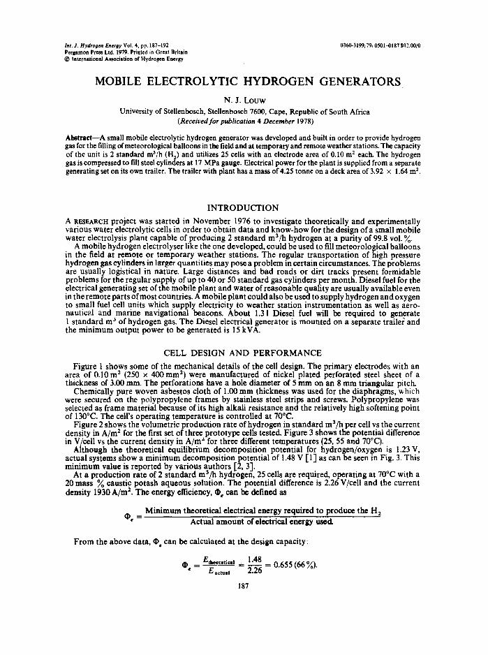
Figure 1 shows some of the mechanical details of the cell design. The primary electrodes with an area of 0.10 m 2 (250 x 400ram 2) were manufactured of nickel plated perforated steel sheet of a thickness of 3.00 ram. The perforations have a hole diameter of 5 mm on an 8 mm triangular pitch.
Chemically pure woven asbestos cloth of 1.00 mm thickness was used for the diaphragms, which were secured on the polypropylene frames by stainless steel strips and screws. Polypropylene was selected as frame material because of its high alkali resistance and the relatively high softening point of 130°C. The cell's operating temperature is controlled at 70°C.
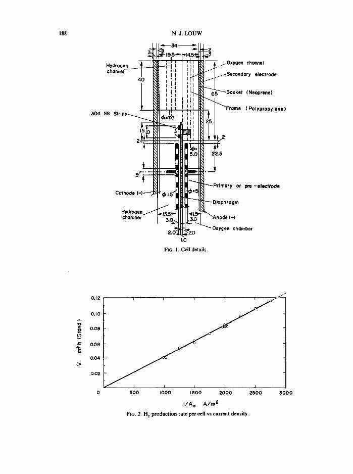
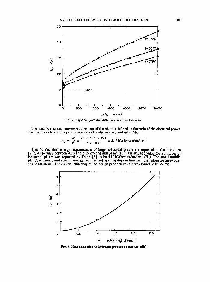
Figure 2 shows the volumetric production rate of hydrogen in standard ma/h per cell vs the current density in A/m 2 for the first set of three prototype cells tested. Figure 3 shows the potential difference in V/cell vs the current density in A/m z for three different temperatures (25, 55 and 70°C).
Although the theoretical equilibrium decomposition potential for hydrogen/oxygen is 1.23 V, actual systems show a minimum decomposition potential of 1.48 V [1] as can be seen in Fig. 3. This minimum value is reported by various authors [2, 3]. o
At a production rate of 2 standard m~/la hydrogen, 25 cells are required, operating at 70 C with a 20 mass % caustic potash aqueous solution. The potential difference is 2.26 V/cell and the current density 1930 A/m 2. The energy efficiency, O~ can he defined as
Minimum theoretical electrical energy required to produce the H2 ~b, = Actual amount of electrical energy used.
From the above data, • e can be calculated at the design capacity:
• = Etb, o,e,i~] = 1.48 = 0.655 (66 %). E,ctu,I 2.26
187
i.O
N. J. L O U W 188
304 S:
SS ~
FIG. 1. Cell details.
onnel
electrode
leoprene)
'o lypropylone)
-e lec t rode
'Io
2 (O
p .
.>
0.12
0.10
0.08
0.06
0.04
0.02
I i I i i
500 I000 1500 2000 2500
I I A e A i m 2
FIG. 2. H 2 production rate per cell vs current density.
~000
MOBILE ELECTROLYTIC HYDROGEN GENERATORS
3.5
3.0
~ 2.5
2.O
1 .5 . . . . . . . . . 1.48V
1~3 , I i I i I , I J I I 0 500 I000 1500 2000 2500 3000
I / A , A / m z
FIG. 3. Single cell potential difference vs current density.
189
The specific electrical energy requirement of the plant is defined as the ratio of the electrical power used by the cells and the production rate of hydrogen in standard m3/h.
25 x 2.26 x 193 w = - -~ = 2 x 1000 = 5.45 kWh/standard m 3.
Specific electrical energy requirements of large industrial plants are reported in the literature [2, 3, 4J to vary between 4.20 and 5.85 kWh/standard m 3 (H2). An average value for a number of mdus tna l plants was reported by G a n n [3] to be 5.10 kWhTstandard m ~ (H2). The small mobile plant 's efficiency and specific energy requirement are therefore in line with the values for large con- ventional plants. The current efficiency at the design production rate was found to be 99.7 ~ .
J ¢
.O
I I I I I
0.5 I.(3 1.5 2,0 2.5
Q m=/h (H=) (Stand.)
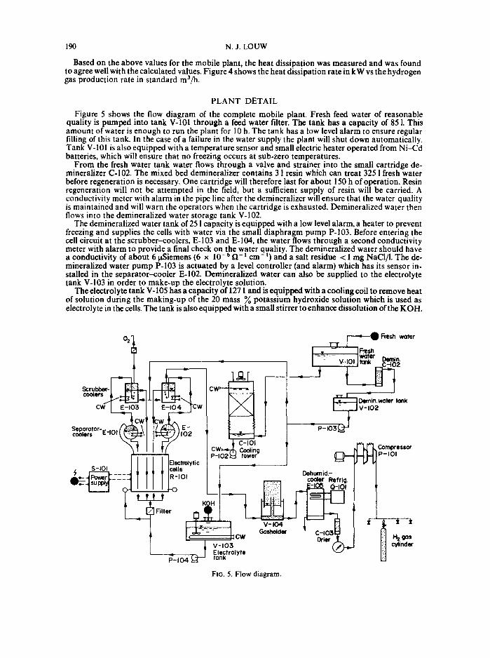
FIG. 4. Heat dissipation vs hydrogen production rate (25 ceils).
190 N.J. LOUW
Based on the above values for the mobile plant, the heat dissipation was measured and was found to agree well with the calculated values. Figure 4 shows the heat dissipation rate in kW vs the hydrogen gas production rate in standard ma/h.
PLANT DETAIL
Figure 5 shows the flow diagram of the complete mobile plant. Fresh feed water of reasonable quality is pumped into tank V-101 through a feed water filter. The tank has a capacity of 851. This amount of water is enough to run the plant for 10 h. The tank has a low level alarm to ensure regular filling of this tank. In the case of a failure in the water supply the plant will shut down automatically. Tank V-101 is also equipped with a temperature sensor and small electric heater operated from Ni-Cd batteries, which will ensure that no freezing occurs at sub-zero temperatures.
From the fresh water tank water flows through a valve and strainer into the small cartridge de- mineralizer C-102. The mixed bed demineralizer contains 31 resin which can treat 325 1 fresh water before regeneration is necessary. One cartridge will therefore last for about 150 h of operation. Resin regeneration will not be attempted in the field, but a sufficient supply of resin will be carried. A conductivity meter with alarm in the pipe line after the demineralizer will ensure that the water quality is maintained and will warn the operators when the cartridge is exhausted. Demineralized water then flows into the demineralized water storage tank V-102.
The demineralized water tank of 251 capacity is equipped with a low level alarm, a heater to prevent freezing and supplies the cells with water via the small diaphragm pump P-103. Before entering the cell circuit at the scrubber-coolers, E-103 and E-104, the water flows through a second conductivity meter with alarm to provide a final check on the water quality. The demineralized water should have a conductivity of about 6 laSiemens (6 x 10- 6 f~- ~ cm- 1) and a salt residue < 1 mg NaCI/I. The de- mineralized water pump P-103 is actuated by a level controller (and alarm) which has its sensor in- stalled in the separator-cooler E-102. Demineralized water can also be supplied to the electrolyte tank V-103 in order to make-up the electrolyte solution.
The electrolyte tank V-105 has a capacity of 1271 and is equipped with a cooling coil to remove heat of solution during the making-up of the 20 mass % potassium hydroxide solution which is used as electrolyte in the cells. The tank is also equipped with a small stirrer to enhance dissolution of the KOH.
o='
, , , I = - v . . t o t
~esh water
F~esh water Dernin.
Scrubber- coolers
Seporotor-~coolers ~-,u,̂ l I ~ \ J I ~ )1~)2 ~ ~ I P-103
S-IOI
Filter
~ Dernin.water tank V-102
02~ C-IOI I CW Coding Compressor P-I tower P-IOI
lytic Dehumid:-
cooler R
KOH
I
FIG. 5. Flow diagram.
v-104 % % Gosholder 03
CW Drier t" I.~ gus . ~ V-103 cylinder
Electrolyte tank
MOBILE ELECTROLYTIC HYDROGEN GENERATORS 191
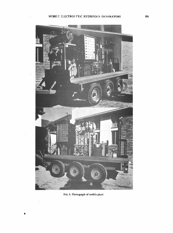
FIG. 6. Photograph of mobile plant.
192 N.J. LOUW
A small leakproof, magnetically coupled, centrifugal pump P- 104 is used to pump the electrolyte from the make-up tank to the cells.
The 25 bipolar cells deliver the oxygen gas with slug-entrained electrolyte into the separator- cooler tank, E-101 and the hydrogen gas enters similarly the separator-cooler, E-102. The electrolyte and gases disengage in these coolers and the electrolyte is cooled before returning to the cells via a filter and manifold. The electrolyte enters the separator-coolers at about 75°C andis cooled to 65°C before being returned to the cells. Cooling water from the cooling tower, C-101, is circulated through the tubes in the separator-coolers, E-101 and E-102. The filling level of the cells are maintained by the level controller on separator-cooler, E-102.
The H 2 and Oz gases bubble through separate scrubber-coolers, E-103 and E-104 where these gases are washed m pure demineralized water to remove any traces of entrained droplets of KOH solution. At the same time some cooling of the gas is obtained. The oxygen then leaves the plant through a pressure equalization orifice. The hydrogen at a temperature of 50°C then enters a small gasholder. V-104. The gasholder has a volume of 60 1 and a water seal of 10 cra water and forms a buffer capacity between the hydrogen producing cells and the compressor.
A potentiometer on the gasholder is used as a sensor to control the d.c. power supply's output current. Two limit switches on the gasholder are used to shut off the power supply and compressor, respectively.
The hydrogen from the gasholder is then cooled to about 20°C in a fin-tube refrigerated cooler and then dried in a silica gel drier. A temperature sensor after the drier acts on the compressor's controller to ensure that only cooled and dehumidified hydrogen is fed to the compressor. A gasmeter is in- stalled between the drier and compressor.
A small industrial evaporative cooling tower, C-101, is used to provide the cooling water through- out the plant.
The hydrogen compressor has three compression stages with two air cooled interstage coolers. The compressor's cylinders are also air cooled. The final pressure of the hydrogen is 17 MPa (gauge). The high pressure hydrogen manifold has four valves and tubes for the simultaneous filling of four gas cylinders. The high pressure gauge acts on the compressor's controller to switch off the com- pressor on reaching the filling pressure of 17 MPa (gauge).
Figure 6 shows a photograph of the mobile hydrogen plant. A six wheeled trailer was selected for the first prototype unit. The total mass of the operating plant is 2.25 mtonne and that of the trailer 2.00 tonn¢. The total mass is therefore 4.25 tonne. The trailer deck dimensions are 3.92 x 1.64 m 2. The plant's height above the deck is 2.10 m and above the ground the height is 2.45 m.
NOMENCLATURE
A = Electrode surface area (either anode or cathode) of one cell, m 2. E~ = Single cell potential difference, V. I = Current, A.
VQ.= Dissipated heat, kW. Volumetric production rate of hydrogen, standard m3/h.
w., = Specific electrical energy requirement, kWh/standard m a (H2). W = Electrical power, kW. cb: = Fractional energy efficiency for hydrogen production.
Abbreviations
C = Controller. CA = Conductivity meter and alarm.
CW = Cooling water. L 1 ; L 2 = Limit switches.
LA = Level alarm. LC = Level controller.
POT = Potentiometer. TI = Temperature indicator.
REFERENCES
1. D. J. PICKETT, Electrochemical Reactor Design, p. 14. Elsevier Scientific Publ. Co. (1977). 2. BAMAG, Verfahrenstechnik, BAMAG Water Electrolysers, Tech. Rep. 6.1, p. 1. 3. A. GAIn4, Ober die Herstellung yon Wasserstoff durch Wasserelektrolyse, Deutsche Luft- und Raumfahrt
Mitteilung, 74-39, p. 42 (1974)~ 4. Constructors JOHN BROWN, CJB Electrolysers, Tech. Bull. p. 1.