Embed Size (px)
Citation preview
The Graduate School of Information Technology and TelecommunicatThe Graduate School of Information Technology and Telecommunications, INHA Universityions, INHA Universityhttp://http://multinet.inha.ac.krmultinet.inha.ac.kr
Multimedia Network Lab.Multimedia Network Lab.
Mobile Computing
Chapter 2: Wireless Transmission
Prof. Sang-Jo Yoo
2The Graduate School of Information Technology and TelecommunicatThe Graduate School of Information Technology and Telecommunications, INHA Universityions, INHA University
http://multinet.inha.ac.kr Multimedia Network LabMultimedia Network Lab..
ContentsFrequencies for communications
Signals
Antennars
Signal propagation
Multiplexing
Modulation
Spread spectrum technologies
Cell structure
3The Graduate School of Information Technology and TelecommunicatThe Graduate School of Information Technology and Telecommunications, INHA Universityions, INHA University
http://multinet.inha.ac.kr Multimedia Network LabMultimedia Network Lab..
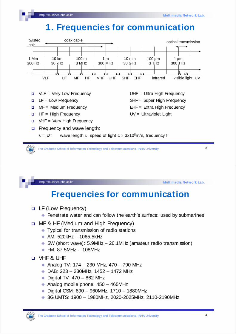
1. Frequencies for communication
VLF = Very Low Frequency UHF = Ultra High Frequency
LF = Low Frequency SHF = Super High Frequency
MF = Medium Frequency EHF = Extra High Frequency
HF = High Frequency UV = Ultraviolet Light
VHF = Very High Frequency
Frequency and wave length:λ = c/f wave length λ, speed of light c ≅ 3x10⁸m/s, frequency f
1 Mm300 Hz
10 km30 kHz
100 m3 MHz
1 m300 MHz
10 mm30 GHz
100 µm3 THz
1 µm300 THz
visible lightVLF LF MF HF VHF UHF SHF EHF infrared UV
optical transmissioncoax cabletwisted pair
4The Graduate School of Information Technology and TelecommunicatThe Graduate School of Information Technology and Telecommunications, INHA Universityions, INHA University
http://multinet.inha.ac.kr Multimedia Network LabMultimedia Network Lab..
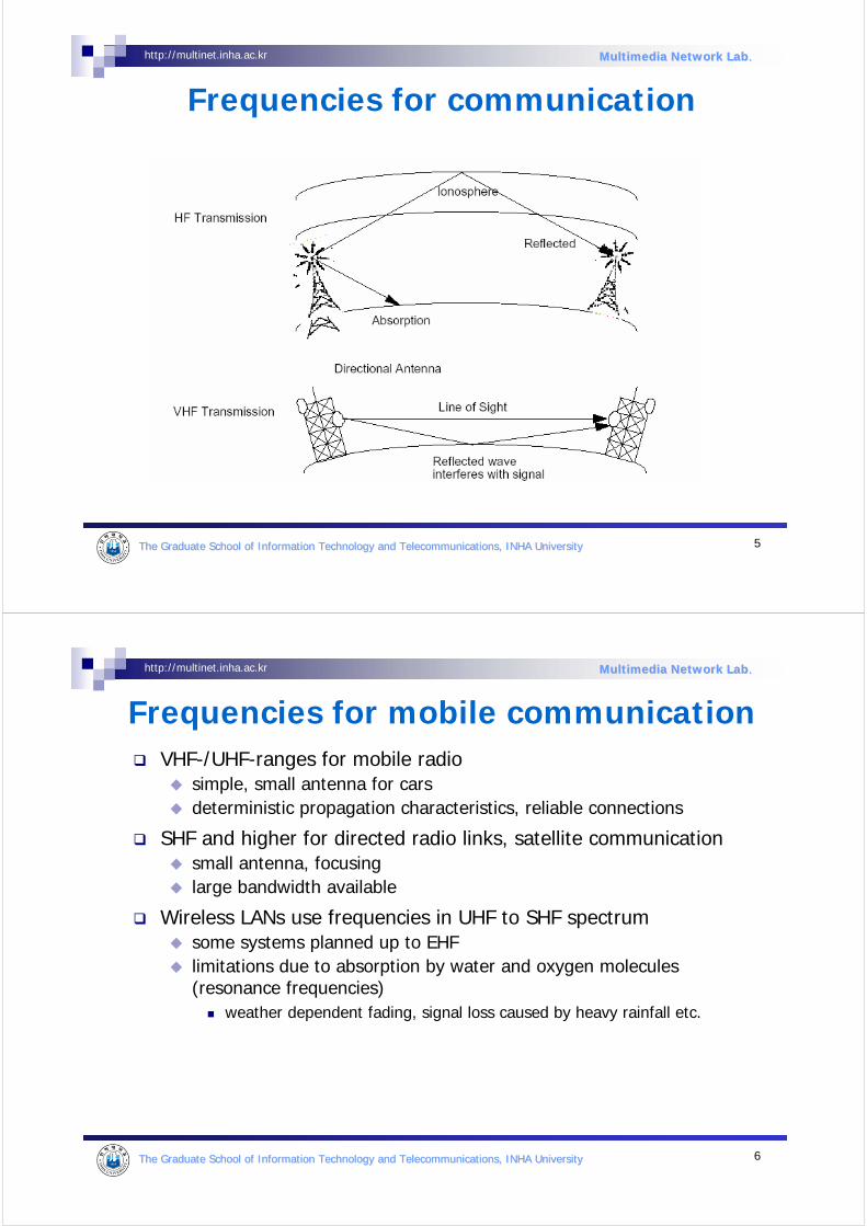
Frequencies for communicationLF (Low Frequency)
Penetrate water and can follow the earth’s surface: used by submarines
MF & HF (Medium and High Frequency)Typical for transmission of radio stations AM: 520kHz – 1065.5kHzSW (short wave): 5.9MHz – 26.1MHz (amateur radio transmission)FM: 87.5MHz - 108MHz
VHF & UHFAnalog TV: 174 – 230 MHz, 470 – 790 MHzDAB: 223 – 230MHz, 1452 – 1472 MHzDigital TV: 470 – 862 MHzAnalog mobile phone: 450 – 465MHzDigital GSM: 890 – 960MHz, 1710 – 1880MHz3G UMTS: 1900 – 1980MHz, 2020-2025MHz, 2110-2190MHz
5The Graduate School of Information Technology and TelecommunicatThe Graduate School of Information Technology and Telecommunications, INHA Universityions, INHA University
http://multinet.inha.ac.kr Multimedia Network LabMultimedia Network Lab..
Frequencies for communication
6The Graduate School of Information Technology and TelecommunicatThe Graduate School of Information Technology and Telecommunications, INHA Universityions, INHA University
http://multinet.inha.ac.kr Multimedia Network LabMultimedia Network Lab..
Frequencies for mobile communicationVHF-/UHF-ranges for mobile radio
simple, small antenna for carsdeterministic propagation characteristics, reliable connections
SHF and higher for directed radio links, satellite communicationsmall antenna, focusinglarge bandwidth available
Wireless LANs use frequencies in UHF to SHF spectrumsome systems planned up to EHFlimitations due to absorption by water and oxygen molecules (resonance frequencies)
weather dependent fading, signal loss caused by heavy rainfall etc.
7The Graduate School of Information Technology and TelecommunicatThe Graduate School of Information Technology and Telecommunications, INHA Universityions, INHA University
http://multinet.inha.ac.kr Multimedia Network LabMultimedia Network Lab..
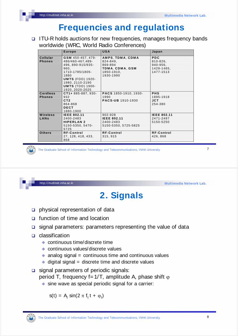
Frequencies and regulationsITU-R holds auctions for new frequencies, manages frequency bands worldwide (WRC, World Radio Conferences) Europe US A Japan
Cellu lar Phones
G SM 450-457, 479-486/460-467,489-496, 890-915/935-960, 1710-1785/1805-1880 UM TS (FD D) 1920-1980, 2110-2190 UM TS (TD D) 1900-1920, 2020-2025
AM PS , TDM A , CD M A 824-849, 869-894 TD M A , C DM A , G SM 1850-1910, 1930-1990
PDC 810-826, 940-956, 1429-1465, 1477-1513
Cordless Phones
CT1+ 885-887, 930-932 CT2 864-868 DECT 1880-1900
P AC S 1850-1910, 1930-1990 P AC S-U B 1910-1930
PHS 1895-1918 JCT 254-380
W ireless LAN s
IEEE 802.11 2400-2483 HIPER LAN 2 5150-5350, 5470-5725
902-928 IEEE 802.11 2400-2483 5150-5350, 5725-5825
IEEE 802.11 2471-2497 5150-5250
O thers RF-C ontrol 27, 128, 418, 433, 868
RF-Contro l 315, 915
RF-Contro l 426, 868
8The Graduate School of Information Technology and TelecommunicatThe Graduate School of Information Technology and Telecommunications, INHA Universityions, INHA University
http://multinet.inha.ac.kr Multimedia Network LabMultimedia Network Lab..
2. Signals physical representation of data
function of time and location
signal parameters: parameters representing the value of data
classificationcontinuous time/discrete timecontinuous values/discrete valuesanalog signal = continuous time and continuous valuesdigital signal = discrete time and discrete values
signal parameters of periodic signals: period T, frequency f=1/T, amplitude A, phase shift ϕ
sine wave as special periodic signal for a carrier:
s(t) = At sin(2 π ft t + ϕt)
9The Graduate School of Information Technology and TelecommunicatThe Graduate School of Information Technology and Telecommunications, INHA Universityions, INHA University
http://multinet.inha.ac.kr Multimedia Network LabMultimedia Network Lab..
Fourier representation of periodic signals
)2cos()2sin(2
1)(
11
nftbnftactgn
nn
n ππ ∑∑∞
=
∞
=
++=
1
0
1
0
t t
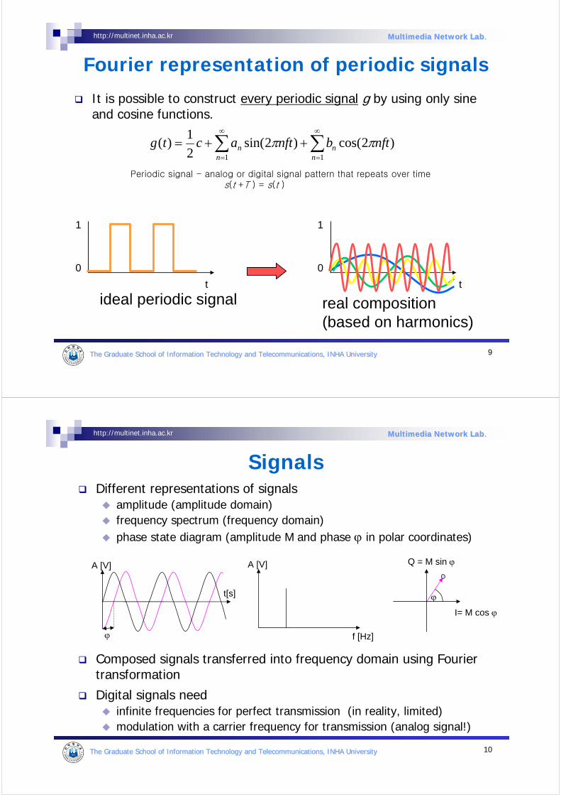
ideal periodic signal real composition(based on harmonics)
It is possible to construct every periodic signal g by using only sine and cosine functions.
Periodic signal - analog or digital signal pattern that repeats over times(t +T ) = s(t )
10The Graduate School of Information Technology and TelecommunicatThe Graduate School of Information Technology and Telecommunications, INHA Universityions, INHA University
http://multinet.inha.ac.kr Multimedia Network LabMultimedia Network Lab..
Different representations of signals amplitude (amplitude domain)frequency spectrum (frequency domain)phase state diagram (amplitude M and phase ϕ in polar coordinates)
Composed signals transferred into frequency domain using Fouriertransformation
Digital signals needinfinite frequencies for perfect transmission (in reality, limited) modulation with a carrier frequency for transmission (analog signal!)
Signals
f [Hz]
A [V]
ϕ
I= M cos ϕ
Q = M sin ϕ
ϕ
A [V]
t[s]
11The Graduate School of Information Technology and TelecommunicatThe Graduate School of Information Technology and Telecommunications, INHA Universityions, INHA University
http://multinet.inha.ac.kr Multimedia Network LabMultimedia Network Lab..
Radiation and reception of electromagnetic waves, coupling of wires to space for radio transmission
Isotropic radiator: equal radiation in all directions (three dimensional) - only a theoretical reference antenna
Real antennas always have directive effects (vertically and/or horizontally)
Radiation pattern: measurement of radiation around an antenna
3. Antennas: isotropic radiator
zy
x
z
y x idealisotropicradiator
12The Graduate School of Information Technology and TelecommunicatThe Graduate School of Information Technology and Telecommunications, INHA Universityions, INHA University
http://multinet.inha.ac.kr Multimedia Network LabMultimedia Network Lab..
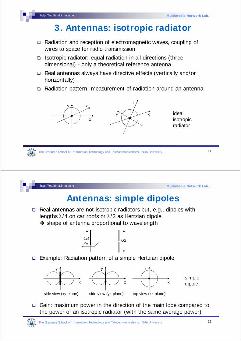
Antennas: simple dipolesReal antennas are not isotropic radiators but, e.g., dipoles with lengths λ/4 on car roofs or λ/2 as Hertzian dipole
shape of antenna proportional to wavelength
Example: Radiation pattern of a simple Hertzian dipole
Gain: maximum power in the direction of the main lobe compared to the power of an isotropic radiator (with the same average power)
side view (xy-plane)
x
y
side view (yz-plane)
z
y
top view (xz-plane)
x
z
simpledipole
λ/4 λ/2
13The Graduate School of Information Technology and TelecommunicatThe Graduate School of Information Technology and Telecommunications, INHA Universityions, INHA University
http://multinet.inha.ac.kr Multimedia Network LabMultimedia Network Lab..
Antennas: directed and sectorized
side view (xy-plane)
x
y
side view (yz-plane)
z
y
top view (xz-plane)
x
z
top view, 3 sector
x
z
top view, 6 sector
x
z
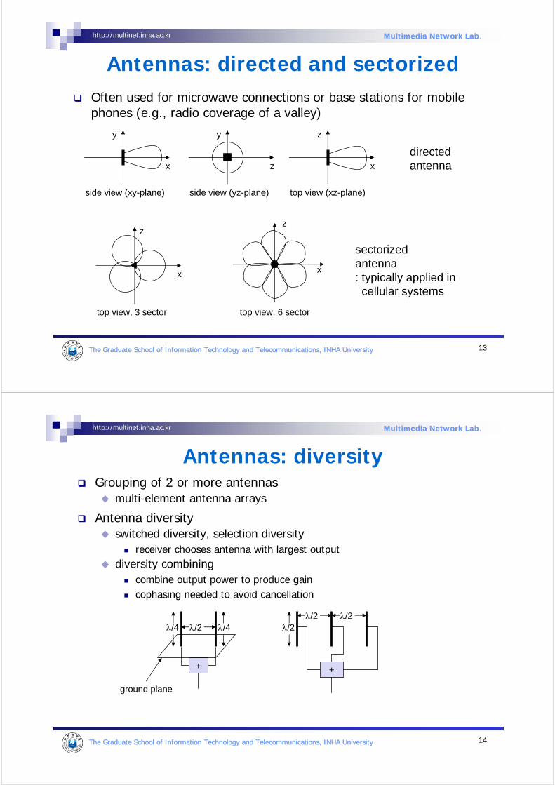
Often used for microwave connections or base stations for mobilephones (e.g., radio coverage of a valley)
directedantenna
sectorizedantenna: typically applied incellular systems
14The Graduate School of Information Technology and TelecommunicatThe Graduate School of Information Technology and Telecommunications, INHA Universityions, INHA University
http://multinet.inha.ac.kr Multimedia Network LabMultimedia Network Lab..
Antennas: diversityGrouping of 2 or more antennas
multi-element antenna arrays
Antenna diversityswitched diversity, selection diversity
receiver chooses antenna with largest outputdiversity combining
combine output power to produce gaincophasing needed to avoid cancellation
+
λ/4λ/2λ/4
ground plane
λ/2λ/2
+
λ/2
15The Graduate School of Information Technology and TelecommunicatThe Graduate School of Information Technology and Telecommunications, INHA Universityions, INHA University
http://multinet.inha.ac.kr Multimedia Network LabMultimedia Network Lab..
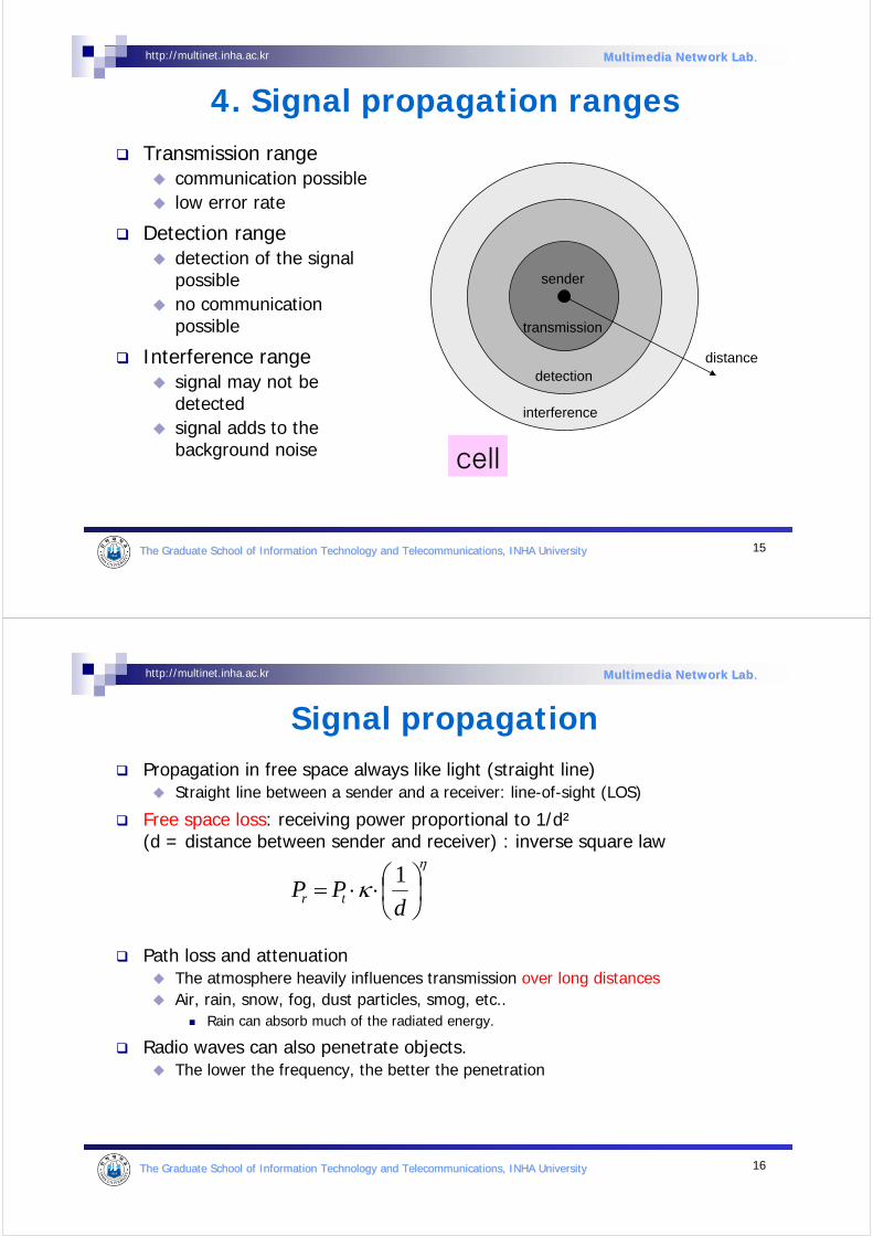
4. Signal propagation ranges
distance
sender
transmission
detection
interference
Transmission rangecommunication possiblelow error rate
Detection rangedetection of the signal possibleno communication possible
Interference rangesignal may not be detected signal adds to the background noise cell
16The Graduate School of Information Technology and TelecommunicatThe Graduate School of Information Technology and Telecommunications, INHA Universityions, INHA University
http://multinet.inha.ac.kr Multimedia Network LabMultimedia Network Lab..
Signal propagationPropagation in free space always like light (straight line)
Straight line between a sender and a receiver: line-of-sight (LOS)
Free space loss: receiving power proportional to 1/d²(d = distance between sender and receiver) : inverse square law
Path loss and attenuationThe atmosphere heavily influences transmission over long distancesAir, rain, snow, fog, dust particles, smog, etc..
Rain can absorb much of the radiated energy.
Radio waves can also penetrate objects.The lower the frequency, the better the penetration
η
κ ⎟⎠⎞
⎜⎝⎛⋅⋅=d
PP tr
1
17The Graduate School of Information Technology and TelecommunicatThe Graduate School of Information Technology and Telecommunications, INHA Universityions, INHA University
http://multinet.inha.ac.kr Multimedia Network LabMultimedia Network Lab..
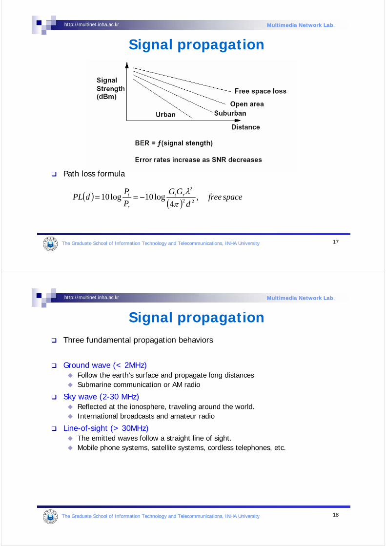
Signal propagation
Path loss formula
( )( )
spacefreed
GG
P
PdPL rt
r
t ,4
log10log1022
2
πλ
−==
18The Graduate School of Information Technology and TelecommunicatThe Graduate School of Information Technology and Telecommunications, INHA Universityions, INHA University
http://multinet.inha.ac.kr Multimedia Network LabMultimedia Network Lab..
Signal propagationThree fundamental propagation behaviors
Ground wave (< 2MHz)Follow the earth’s surface and propagate long distancesSubmarine communication or AM radio
Sky wave (2-30 MHz)Reflected at the ionosphere, traveling around the world.International broadcasts and amateur radio
Line-of-sight (> 30MHz)The emitted waves follow a straight line of sight.Mobile phone systems, satellite systems, cordless telephones, etc.
19The Graduate School of Information Technology and TelecommunicatThe Graduate School of Information Technology and Telecommunications, INHA Universityions, INHA University
http://multinet.inha.ac.kr Multimedia Network LabMultimedia Network Lab..
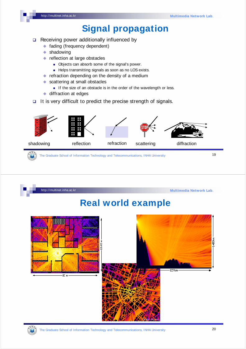
Signal propagationReceiving power additionally influenced by
fading (frequency dependent)shadowingreflection at large obstacles
Objects can absorb some of the signal’s power.Helps transmitting signals as soon as no LOS exists.
refraction depending on the density of a mediumscattering at small obstacles
If the size of an obstacle is in the order of the wavelength or less.diffraction at edges
It is very difficult to predict the precise strength of signals.
reflection scattering diffractionshadowing refraction
20The Graduate School of Information Technology and TelecommunicatThe Graduate School of Information Technology and Telecommunications, INHA Universityions, INHA University
http://multinet.inha.ac.kr Multimedia Network LabMultimedia Network Lab..
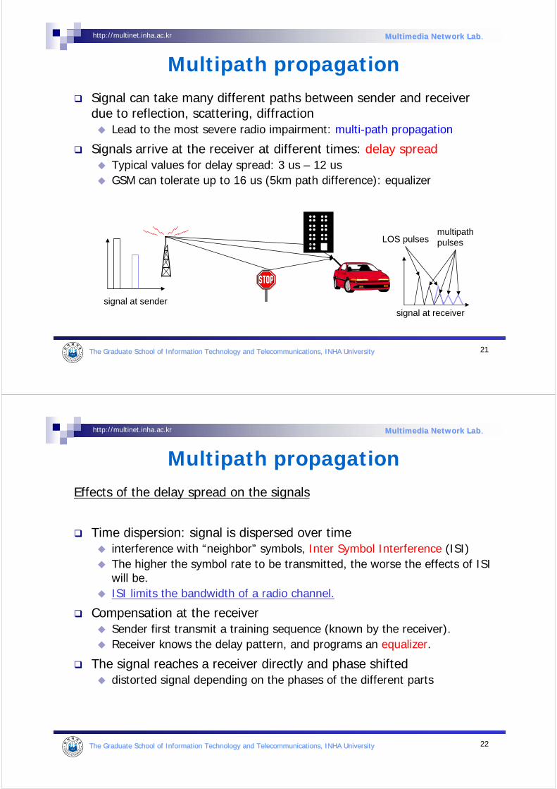
Real world example
21The Graduate School of Information Technology and TelecommunicatThe Graduate School of Information Technology and Telecommunications, INHA Universityions, INHA University
http://multinet.inha.ac.kr Multimedia Network LabMultimedia Network Lab..
Signal can take many different paths between sender and receiverdue to reflection, scattering, diffraction
Lead to the most severe radio impairment: multi-path propagation
Signals arrive at the receiver at different times: delay spreadTypical values for delay spread: 3 us – 12 usGSM can tolerate up to 16 us (5km path difference): equalizer
Multipath propagation
signal at sendersignal at receiver
LOS pulsesmultipathpulses
22The Graduate School of Information Technology and TelecommunicatThe Graduate School of Information Technology and Telecommunications, INHA Universityions, INHA University
http://multinet.inha.ac.kr Multimedia Network LabMultimedia Network Lab..
Effects of the delay spread on the signals
Time dispersion: signal is dispersed over timeinterference with “neighbor” symbols, Inter Symbol Interference (ISI)The higher the symbol rate to be transmitted, the worse the effects of ISI will be.ISI limits the bandwidth of a radio channel.
Compensation at the receiverSender first transmit a training sequence (known by the receiver).Receiver knows the delay pattern, and programs an equalizer.
The signal reaches a receiver directly and phase shifteddistorted signal depending on the phases of the different parts
Multipath propagation
23The Graduate School of Information Technology and TelecommunicatThe Graduate School of Information Technology and Telecommunications, INHA Universityions, INHA University
http://multinet.inha.ac.kr Multimedia Network LabMultimedia Network Lab..
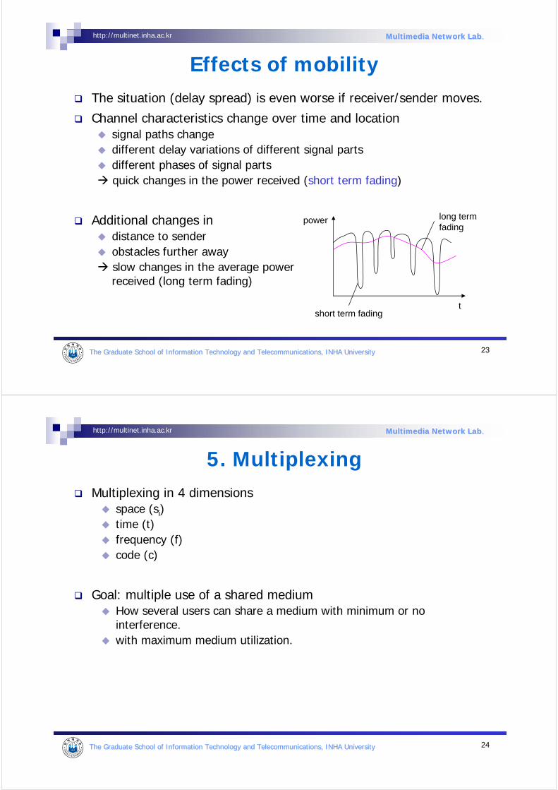
Effects of mobilityThe situation (delay spread) is even worse if receiver/sender moves.
Channel characteristics change over time and location signal paths changedifferent delay variations of different signal partsdifferent phases of signal partsquick changes in the power received (short term fading)
Additional changes indistance to senderobstacles further awayslow changes in the average power received (long term fading)
short term fading
long termfading
t
power
24The Graduate School of Information Technology and TelecommunicatThe Graduate School of Information Technology and Telecommunications, INHA Universityions, INHA University
http://multinet.inha.ac.kr Multimedia Network LabMultimedia Network Lab..
Multiplexing in 4 dimensionsspace (si)time (t)frequency (f)code (c)
Goal: multiple use of a shared mediumHow several users can share a medium with minimum or no interference.with maximum medium utilization.
5. Multiplexing
25The Graduate School of Information Technology and TelecommunicatThe Graduate School of Information Technology and Telecommunications, INHA Universityions, INHA University
http://multinet.inha.ac.kr Multimedia Network LabMultimedia Network Lab..
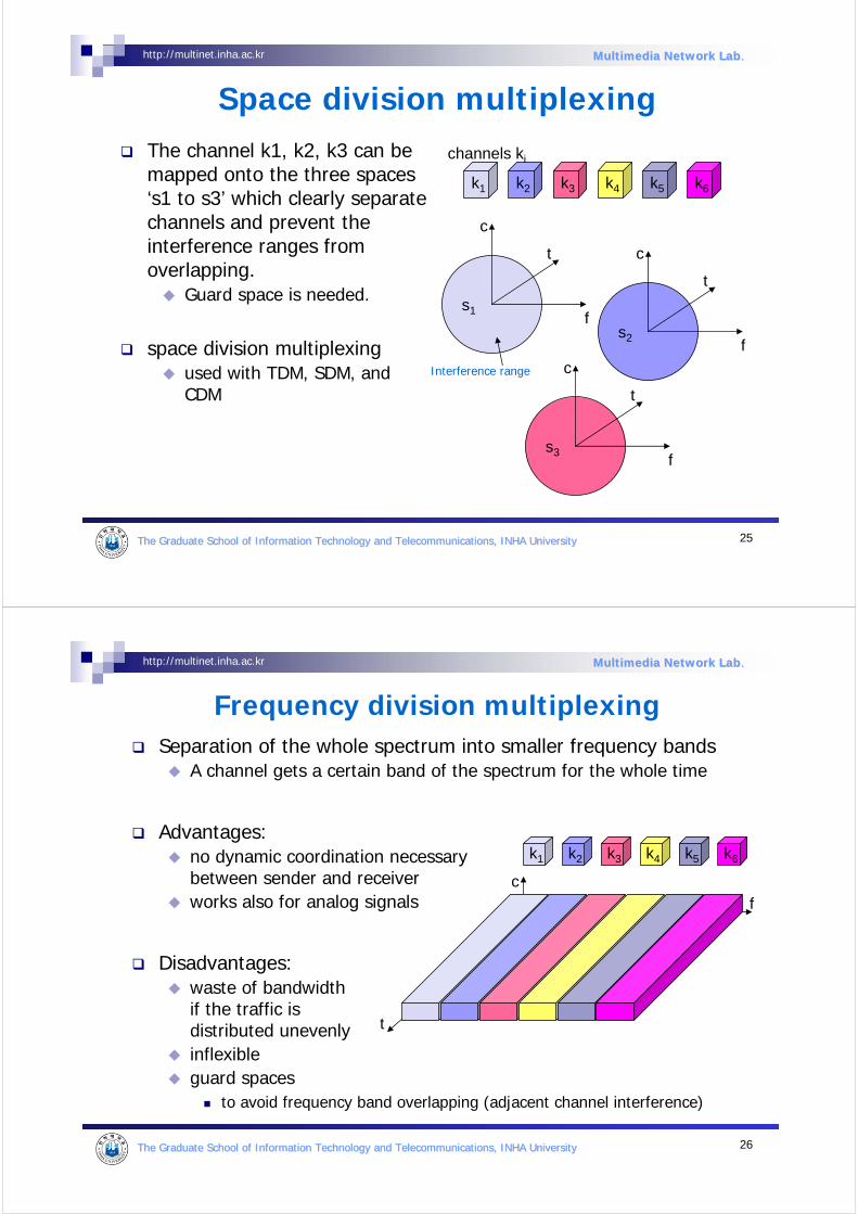
The channel k1, k2, k3 can be mapped onto the three spaces ‘s1 to s3’ which clearly separate channels and prevent the interference ranges from overlapping.
Guard space is needed.
space division multiplexingused with TDM, SDM, and CDM
Space division multiplexing
s2
s3
s1f
t
c
k2 k3 k4 k5 k6k1
f
t
c
f
t
c
channels ki
Interference range
26The Graduate School of Information Technology and TelecommunicatThe Graduate School of Information Technology and Telecommunications, INHA Universityions, INHA University
http://multinet.inha.ac.kr Multimedia Network LabMultimedia Network Lab..
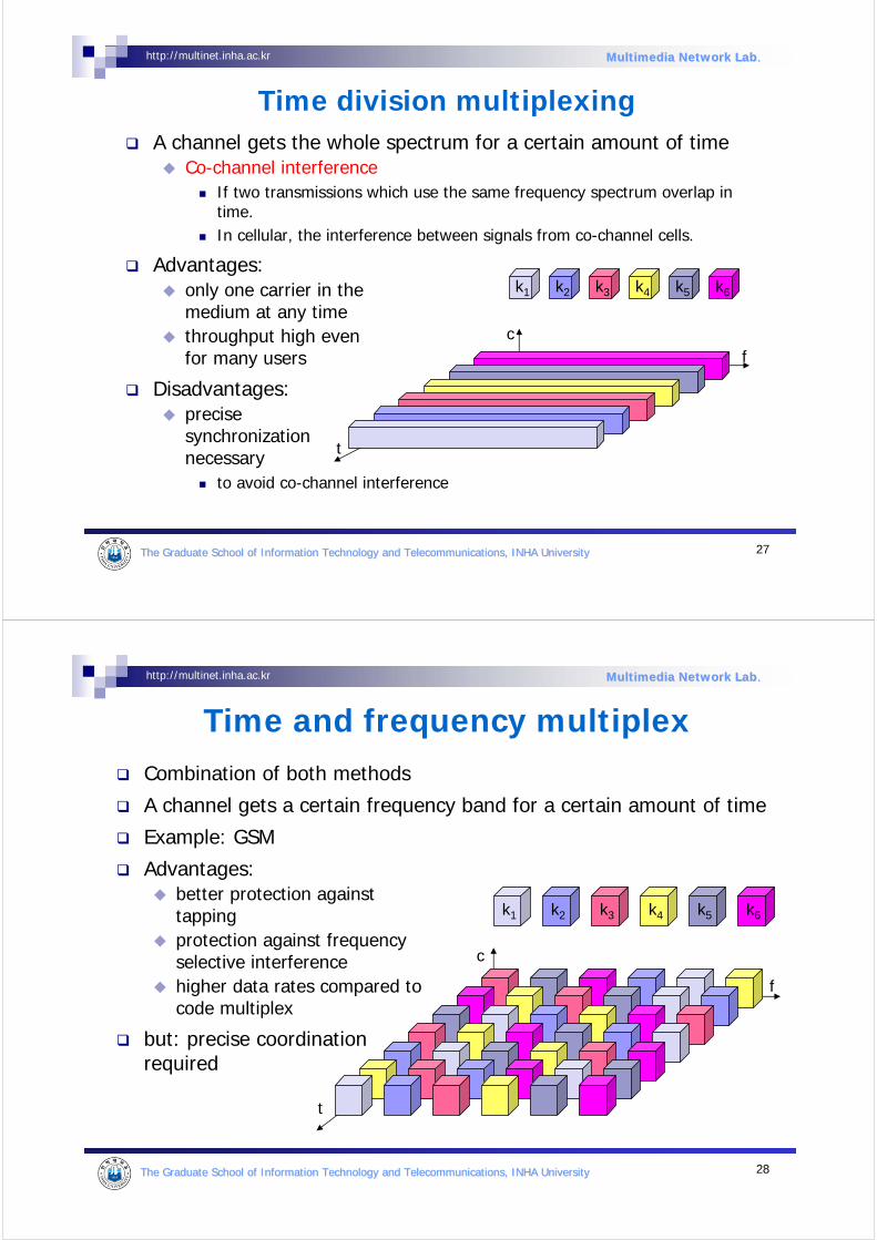
Frequency division multiplexingSeparation of the whole spectrum into smaller frequency bands
A channel gets a certain band of the spectrum for the whole time
Advantages:no dynamic coordination necessarybetween sender and receiverworks also for analog signals
Disadvantages:waste of bandwidth if the traffic is distributed unevenlyinflexibleguard spaces
to avoid frequency band overlapping (adjacent channel interference)
k2 k3 k4 k5 k6k1
f
t
c
27The Graduate School of Information Technology and TelecommunicatThe Graduate School of Information Technology and Telecommunications, INHA Universityions, INHA University
http://multinet.inha.ac.kr Multimedia Network LabMultimedia Network Lab..
f
t
c
k2 k3 k4 k5 k6k1
Time division multiplexingA channel gets the whole spectrum for a certain amount of time
Co-channel interferenceIf two transmissions which use the same frequency spectrum overlap in time.In cellular, the interference between signals from co-channel cells.
Advantages:only one carrier in themedium at any timethroughput high even for many users
Disadvantages:precise synchronization necessary
to avoid co-channel interference
28The Graduate School of Information Technology and TelecommunicatThe Graduate School of Information Technology and Telecommunications, INHA Universityions, INHA University
http://multinet.inha.ac.kr Multimedia Network LabMultimedia Network Lab..
f
Time and frequency multiplexCombination of both methods
A channel gets a certain frequency band for a certain amount of time
Example: GSM
Advantages:better protection against tappingprotection against frequency selective interferencehigher data rates compared tocode multiplex
but: precise coordinationrequired
t
c
k2 k3 k4 k5 k6k1

29The Graduate School of Information Technology and TelecommunicatThe Graduate School of Information Technology and Telecommunications, INHA Universityions, INHA University
http://multinet.inha.ac.kr Multimedia Network LabMultimedia Network Lab..
Code division multiplexingEach channel has a unique code (language)
All channels use the same spectrum at the same time
Advantages:bandwidth efficient (code space is huge)no coordination and synchronization necessarygood protection against interference and tapping
Disadvantages:more complex signal regenerationPrecise power control is required.
Implemented using spread spectrum technology
k2 k3 k4 k5 k6k1
f
t
c
30The Graduate School of Information Technology and TelecommunicatThe Graduate School of Information Technology and Telecommunications, INHA Universityions, INHA University
http://multinet.inha.ac.kr Multimedia Network LabMultimedia Network Lab..
6. ModulationDigital modulation
digital data is translated into an analog signal (baseband)ASK, FSK, PSK - main focus in this chapterdifferences in spectral efficiency, power efficiency, robustness
Analog modulationshifts center frequency of baseband signal up to the radio carrier
Motivation of analog modulationsmaller antennas (e.g., λ/4)frequency division multiplexingmedium characteristics
path loss, penetration , reflection, scattering, diffraction depend on the wavelength of the signal
Basic schemesAmplitude Modulation (AM)Frequency Modulation (FM)Phase Modulation (PM)
31The Graduate School of Information Technology and TelecommunicatThe Graduate School of Information Technology and Telecommunications, INHA Universityions, INHA University
http://multinet.inha.ac.kr Multimedia Network LabMultimedia Network Lab..
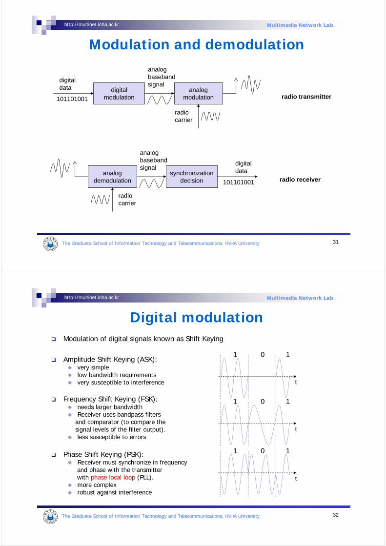
Modulation and demodulation
synchronizationdecision
digitaldataanalog
demodulation
radiocarrier
analogbasebandsignal
101101001 radio receiver
digitalmodulation
digitaldata analog
modulation
radiocarrier
analogbasebandsignal
101101001 radio transmitter
32The Graduate School of Information Technology and TelecommunicatThe Graduate School of Information Technology and Telecommunications, INHA Universityions, INHA University
http://multinet.inha.ac.kr Multimedia Network LabMultimedia Network Lab..
Digital modulationModulation of digital signals known as Shift Keying
Amplitude Shift Keying (ASK):very simplelow bandwidth requirementsvery susceptible to interference
Frequency Shift Keying (FSK):needs larger bandwidthReceiver uses bandpass filters
and comparator (to compare the signal levels of the filter output).less susceptible to errors
Phase Shift Keying (PSK):Receiver must synchronize in frequency and phase with the transmitter with phase local loop (PLL).more complexrobust against interference
1 0 1
t
1 0 1
t
1 0 1
t
33The Graduate School of Information Technology and TelecommunicatThe Graduate School of Information Technology and Telecommunications, INHA Universityions, INHA University
http://multinet.inha.ac.kr Multimedia Network LabMultimedia Network Lab..
Advanced Frequency Shift KeyingSpecial pre-computation avoids sudden phase shifts
Sudden changes in phase cause high frequencies undesired side-effect
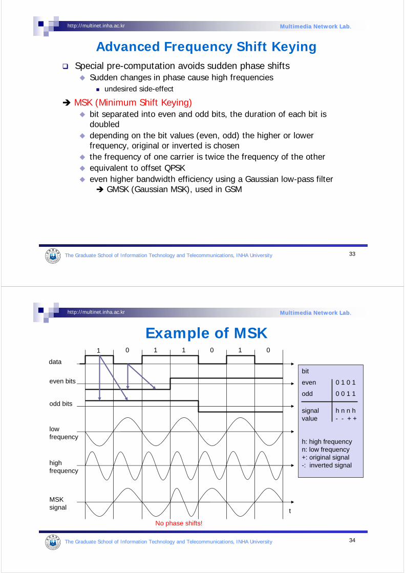
MSK (Minimum Shift Keying)bit separated into even and odd bits, the duration of each bit is doubled depending on the bit values (even, odd) the higher or lower frequency, original or inverted is chosenthe frequency of one carrier is twice the frequency of the otherequivalent to offset QPSKeven higher bandwidth efficiency using a Gaussian low-pass filter
GMSK (Gaussian MSK), used in GSM
34The Graduate School of Information Technology and TelecommunicatThe Graduate School of Information Technology and Telecommunications, INHA Universityions, INHA University
http://multinet.inha.ac.kr Multimedia Network LabMultimedia Network Lab..
Example of MSK
data
even bits
odd bits
1 1 1 1 000
t
low frequency
highfrequency
MSKsignal
bit
even 0 1 0 1
odd 0 0 1 1
signal h n n hvalue - - + +
h: high frequencyn: low frequency+: original signal-: inverted signal
No phase shifts!
35The Graduate School of Information Technology and TelecommunicatThe Graduate School of Information Technology and Telecommunications, INHA Universityions, INHA University
http://multinet.inha.ac.kr Multimedia Network LabMultimedia Network Lab..
Advanced Phase Shift Keying
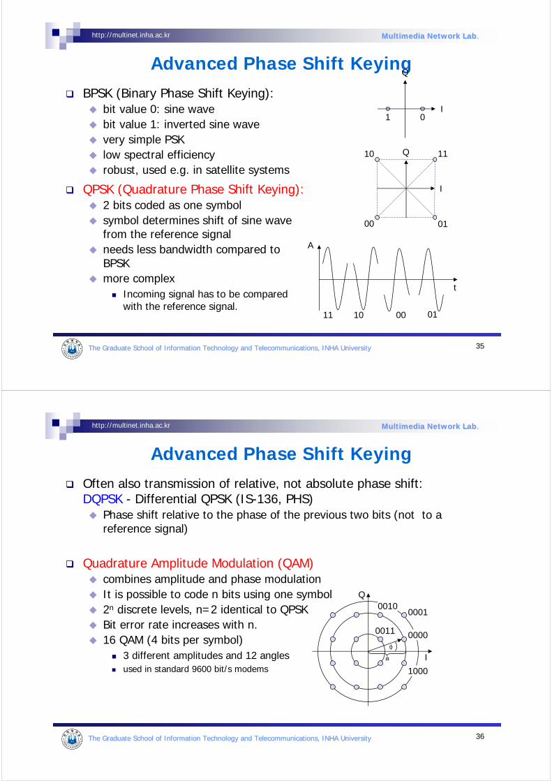
BPSK (Binary Phase Shift Keying):bit value 0: sine wavebit value 1: inverted sine wavevery simple PSKlow spectral efficiencyrobust, used e.g. in satellite systems
QPSK (Quadrature Phase Shift Keying):2 bits coded as one symbolsymbol determines shift of sine wavefrom the reference signalneeds less bandwidth compared to BPSKmore complex
Incoming signal has to be compared with the reference signal.
11 10 00 01
Q
I01
Q
I
11
01
10
00
A
t
36The Graduate School of Information Technology and TelecommunicatThe Graduate School of Information Technology and Telecommunications, INHA Universityions, INHA University
http://multinet.inha.ac.kr Multimedia Network LabMultimedia Network Lab..
Advanced Phase Shift Keying
Often also transmission of relative, not absolute phase shift: DQPSK - Differential QPSK (IS-136, PHS)
Phase shift relative to the phase of the previous two bits (not to a reference signal)
Quadrature Amplitude Modulation (QAM)combines amplitude and phase modulationIt is possible to code n bits using one symbol2n discrete levels, n=2 identical to QPSKBit error rate increases with n.16 QAM (4 bits per symbol)
3 different amplitudes and 12 anglesused in standard 9600 bit/s modems
0000
0001
0011
1000
Q
I
0010
φ
a
37The Graduate School of Information Technology and TelecommunicatThe Graduate School of Information Technology and Telecommunications, INHA Universityions, INHA University
http://multinet.inha.ac.kr Multimedia Network LabMultimedia Network Lab..
Hierarchical Modulation
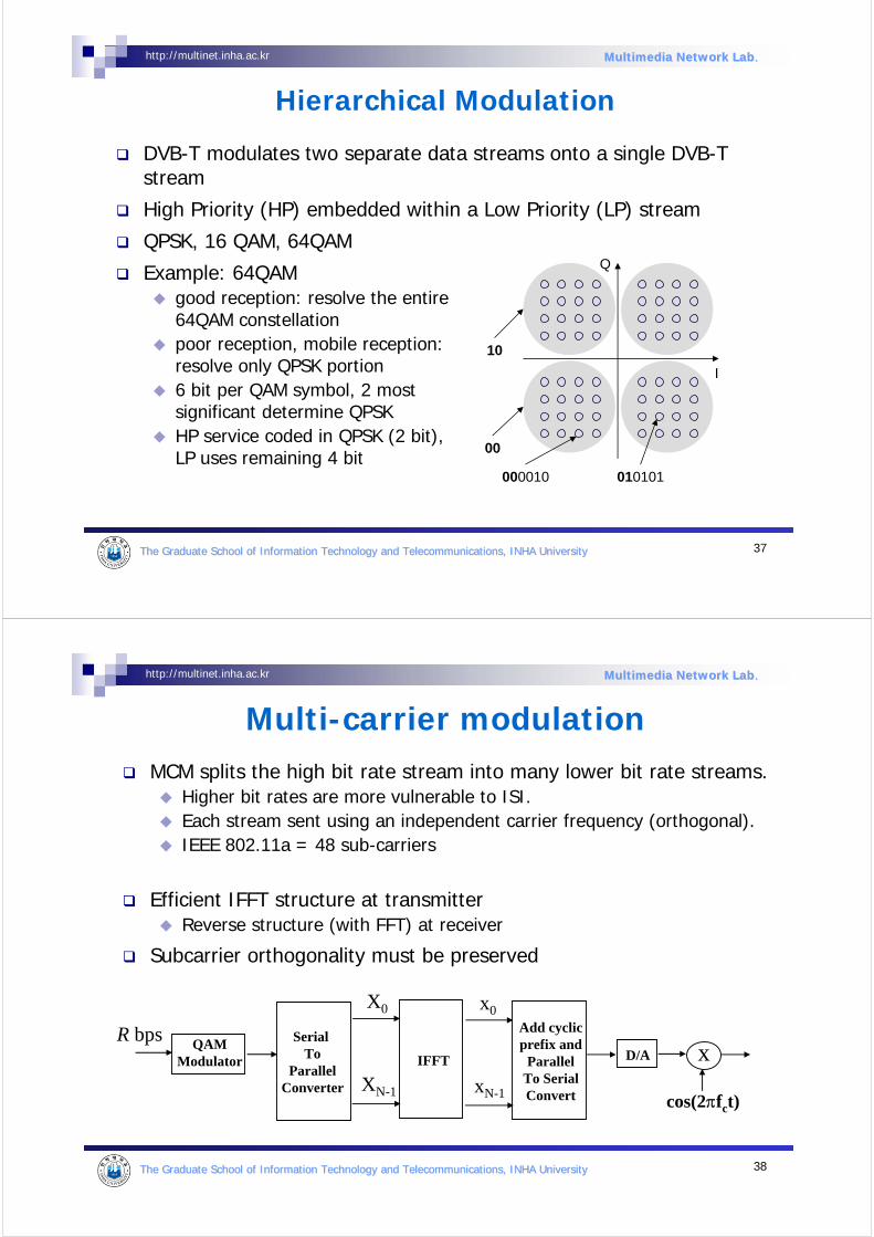
DVB-T modulates two separate data streams onto a single DVB-T stream
High Priority (HP) embedded within a Low Priority (LP) stream
QPSK, 16 QAM, 64QAM
Example: 64QAMgood reception: resolve the entire64QAM constellationpoor reception, mobile reception: resolve only QPSK portion6 bit per QAM symbol, 2 mostsignificant determine QPSKHP service coded in QPSK (2 bit), LP uses remaining 4 bit
Q
I
00
10
000010 010101
38The Graduate School of Information Technology and TelecommunicatThe Graduate School of Information Technology and Telecommunications, INHA Universityions, INHA University
http://multinet.inha.ac.kr Multimedia Network LabMultimedia Network Lab..
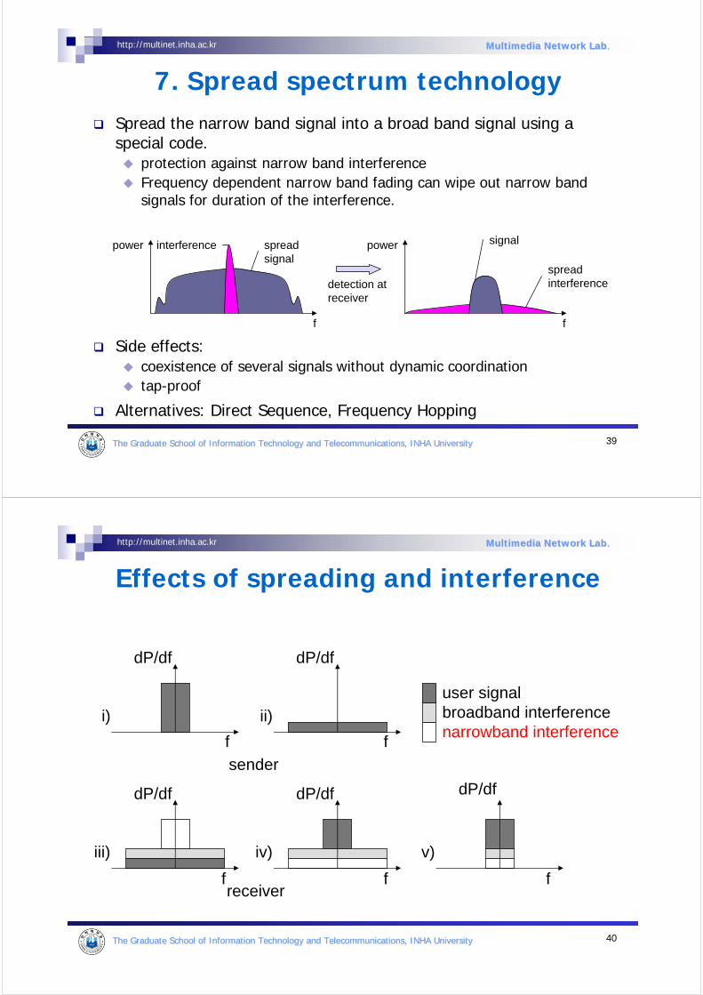
Multi-carrier modulationMCM splits the high bit rate stream into many lower bit rate streams.
Higher bit rates are more vulnerable to ISI.Each stream sent using an independent carrier frequency (orthogonal).IEEE 802.11a = 48 sub-carriers
Efficient IFFT structure at transmitterReverse structure (with FFT) at receiver
Subcarrier orthogonality must be preserved
x
cos(2πfct)
R bpsQAM
Modulator
Serial To
ParallelConverter
IFFT
X0
XN-1
x0
xN-1
Add cyclicprefix and
ParallelTo SerialConvert
D/A
39The Graduate School of Information Technology and TelecommunicatThe Graduate School of Information Technology and Telecommunications, INHA Universityions, INHA University
http://multinet.inha.ac.kr Multimedia Network LabMultimedia Network Lab..
7. Spread spectrum technologySpread the narrow band signal into a broad band signal using a special code.
protection against narrow band interference Frequency dependent narrow band fading can wipe out narrow band signals for duration of the interference.
Side effects:coexistence of several signals without dynamic coordinationtap-proof
Alternatives: Direct Sequence, Frequency Hopping
detection atreceiver
interference spread signal
signal
spreadinterference
f f
power power
40The Graduate School of Information Technology and TelecommunicatThe Graduate School of Information Technology and Telecommunications, INHA Universityions, INHA University
http://multinet.inha.ac.kr Multimedia Network LabMultimedia Network Lab..
Effects of spreading and interference
dP/df
f
i)
dP/df
f
ii)
sender
dP/df
f
iii)
dP/df
f
iv)
receiverf
v)
user signalbroadband interferencenarrowband interference
dP/df
41The Graduate School of Information Technology and TelecommunicatThe Graduate School of Information Technology and Telecommunications, INHA Universityions, INHA University
http://multinet.inha.ac.kr Multimedia Network LabMultimedia Network Lab..
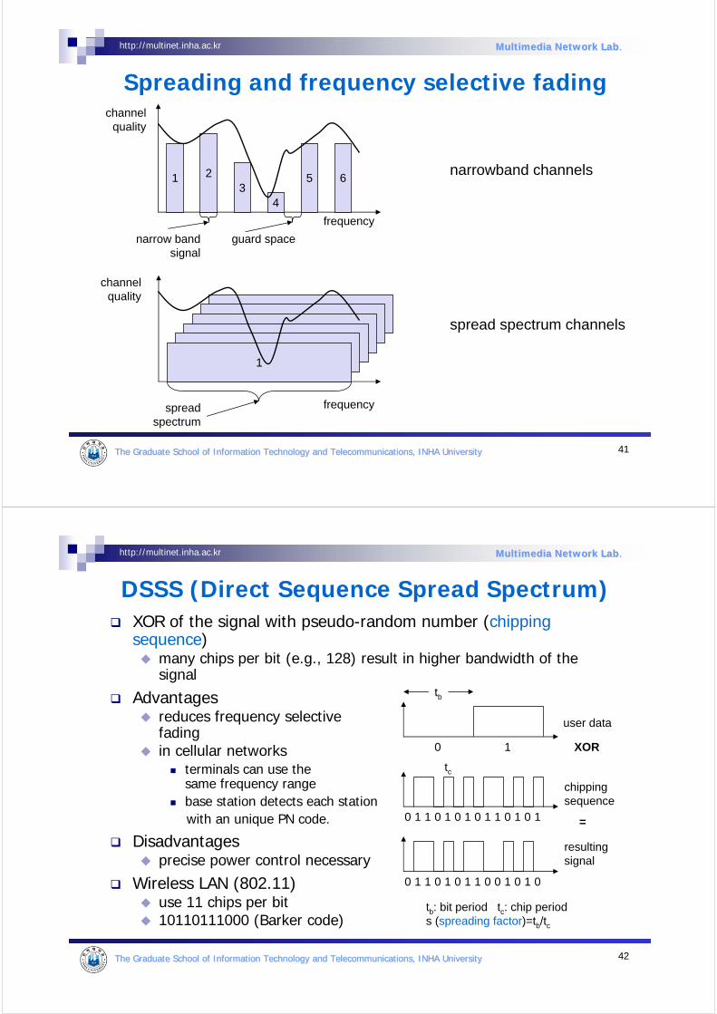
Spreading and frequency selective fading
frequency
channelquality
1 23
4
5 6
narrow bandsignal
guard space
22
22
2
frequency
channelquality
1
spreadspectrum
narrowband channels
spread spectrum channels
42The Graduate School of Information Technology and TelecommunicatThe Graduate School of Information Technology and Telecommunications, INHA Universityions, INHA University
http://multinet.inha.ac.kr Multimedia Network LabMultimedia Network Lab..
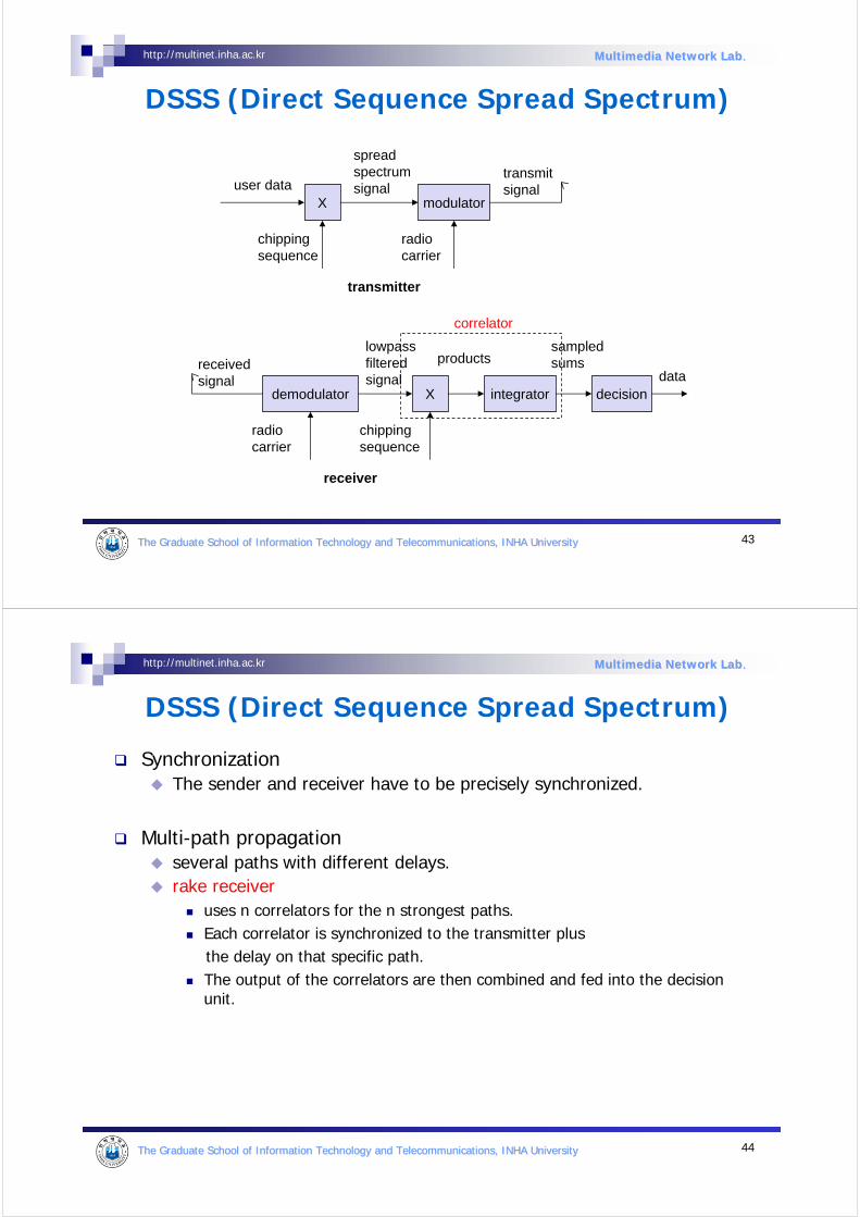
DSSS (Direct Sequence Spread Spectrum)XOR of the signal with pseudo-random number (chipping sequence)
many chips per bit (e.g., 128) result in higher bandwidth of thesignal
Advantagesreduces frequency selective fadingin cellular networks
terminals can use the same frequency rangebase station detects each stationwith an unique PN code.
Disadvantagesprecise power control necessary
Wireless LAN (802.11)use 11 chips per bit10110111000 (Barker code)
user data
chipping sequence
resultingsignal
0 1
0 1 1 0 1 0 1 01 0 0 1 11
XOR
0 1 1 0 0 1 0 11 0 1 0 01
=
tb
tc
tb: bit period tc: chip periods (spreading factor)=tb/tc
43The Graduate School of Information Technology and TelecommunicatThe Graduate School of Information Technology and Telecommunications, INHA Universityions, INHA University
http://multinet.inha.ac.kr Multimedia Network LabMultimedia Network Lab..
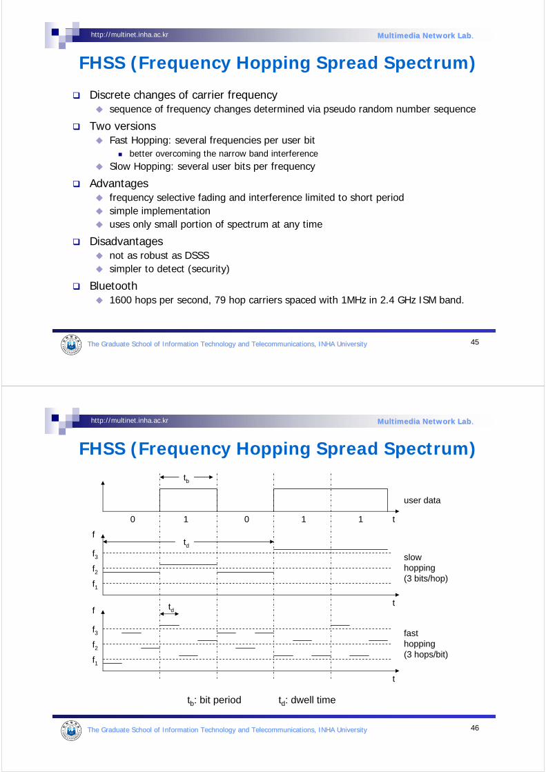
DSSS (Direct Sequence Spread Spectrum)
Xuser data
chippingsequence
modulator
radiocarrier
spreadspectrumsignal
transmitsignal
transmitter
demodulator
receivedsignal
radiocarrier
X
chippingsequence
lowpassfilteredsignal
receiver
integrator
products
decisiondata
sampledsums
correlator
44The Graduate School of Information Technology and TelecommunicatThe Graduate School of Information Technology and Telecommunications, INHA Universityions, INHA University
http://multinet.inha.ac.kr Multimedia Network LabMultimedia Network Lab..
DSSS (Direct Sequence Spread Spectrum)
SynchronizationThe sender and receiver have to be precisely synchronized.
Multi-path propagationseveral paths with different delays.rake receiver
uses n correlators for the n strongest paths.Each correlator is synchronized to the transmitter plus the delay on that specific path.The output of the correlators are then combined and fed into the decision unit.
45The Graduate School of Information Technology and TelecommunicatThe Graduate School of Information Technology and Telecommunications, INHA Universityions, INHA University
http://multinet.inha.ac.kr Multimedia Network LabMultimedia Network Lab..
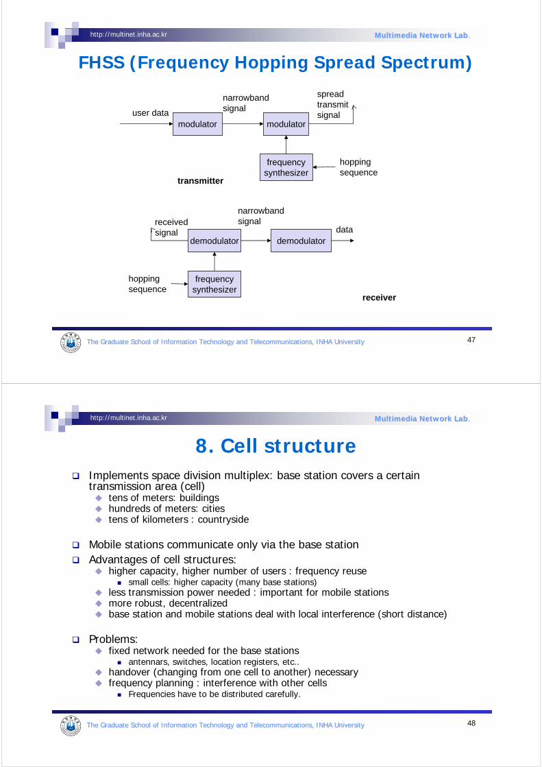
FHSS (Frequency Hopping Spread Spectrum)
Discrete changes of carrier frequencysequence of frequency changes determined via pseudo random number sequence
Two versionsFast Hopping: several frequencies per user bit
better overcoming the narrow band interferenceSlow Hopping: several user bits per frequency
Advantagesfrequency selective fading and interference limited to short periodsimple implementationuses only small portion of spectrum at any time
Disadvantagesnot as robust as DSSSsimpler to detect (security)
Bluetooth1600 hops per second, 79 hop carriers spaced with 1MHz in 2.4 GHz ISM band.
46The Graduate School of Information Technology and TelecommunicatThe Graduate School of Information Technology and Telecommunications, INHA Universityions, INHA University
http://multinet.inha.ac.kr Multimedia Network LabMultimedia Network Lab..
FHSS (Frequency Hopping Spread Spectrum)
user data
slowhopping(3 bits/hop)
fasthopping(3 hops/bit)
0 1
tb
0 1 1 t
f
f1
f2
f3
t
td
f
f1
f2
f3
t
td
tb: bit period td: dwell time
47The Graduate School of Information Technology and TelecommunicatThe Graduate School of Information Technology and Telecommunications, INHA Universityions, INHA University
http://multinet.inha.ac.kr Multimedia Network LabMultimedia Network Lab..
FHSS (Frequency Hopping Spread Spectrum)
modulatoruser data
hoppingsequence
modulator
narrowbandsignal
spreadtransmitsignal
transmitter
receivedsignal
receiver
demodulatordata
frequencysynthesizer
hoppingsequence
demodulator
frequencysynthesizer
narrowbandsignal
48The Graduate School of Information Technology and TelecommunicatThe Graduate School of Information Technology and Telecommunications, INHA Universityions, INHA University
http://multinet.inha.ac.kr Multimedia Network LabMultimedia Network Lab..
8. Cell structureImplements space division multiplex: base station covers a certain transmission area (cell)
tens of meters: buildingshundreds of meters: citiestens of kilometers : countryside
Mobile stations communicate only via the base stationAdvantages of cell structures:
higher capacity, higher number of users : frequency reusesmall cells: higher capacity (many base stations)
less transmission power needed : important for mobile stationsmore robust, decentralizedbase station and mobile stations deal with local interference (short distance)
Problems:fixed network needed for the base stations
antennars, switches, location registers, etc..handover (changing from one cell to another) necessaryfrequency planning : interference with other cells
Frequencies have to be distributed carefully.
49The Graduate School of Information Technology and TelecommunicatThe Graduate School of Information Technology and Telecommunications, INHA Universityions, INHA University
http://multinet.inha.ac.kr Multimedia Network LabMultimedia Network Lab..
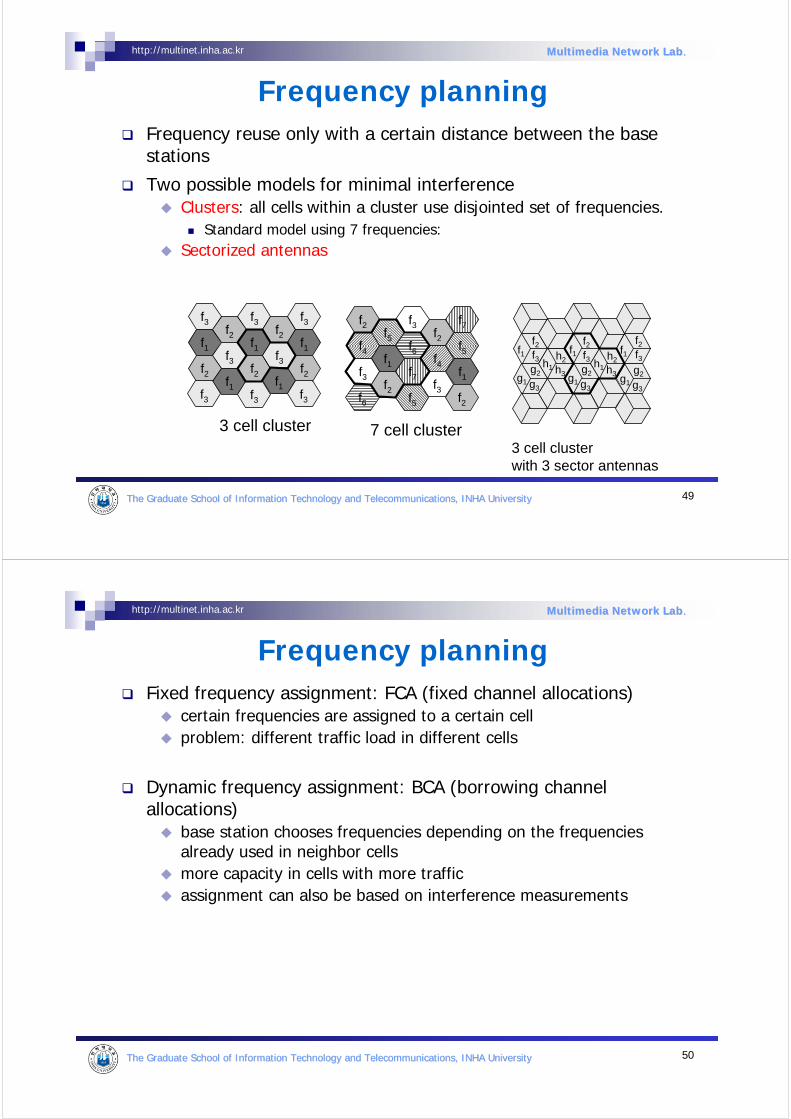
Frequency planning Frequency reuse only with a certain distance between the base stations
Two possible models for minimal interferenceClusters: all cells within a cluster use disjointed set of frequencies.
Standard model using 7 frequencies:Sectorized antennas
f1f2
f3f2
f1
f1
f2
f3f2
f3f1
f2f1
f3f3
f3f3
f3
f4f5
f1f3
f2
f6
f7
f3f2
f4f5
f1f3
f5f6
f7f2
f2
3 cell cluster 7 cell cluster
f1f1 f1f2f3
f2f3
f2f3
h1
h2
h3g1
g2
g3
h1
h2
h3g1
g2
g3g1
g2
g3
3 cell clusterwith 3 sector antennas
50The Graduate School of Information Technology and TelecommunicatThe Graduate School of Information Technology and Telecommunications, INHA Universityions, INHA University
http://multinet.inha.ac.kr Multimedia Network LabMultimedia Network Lab..
Frequency planning Fixed frequency assignment: FCA (fixed channel allocations)
certain frequencies are assigned to a certain cellproblem: different traffic load in different cells
Dynamic frequency assignment: BCA (borrowing channel allocations)
base station chooses frequencies depending on the frequencies already used in neighbor cellsmore capacity in cells with more trafficassignment can also be based on interference measurements
51The Graduate School of Information Technology and TelecommunicatThe Graduate School of Information Technology and Telecommunications, INHA Universityions, INHA University
http://multinet.inha.ac.kr Multimedia Network LabMultimedia Network Lab..
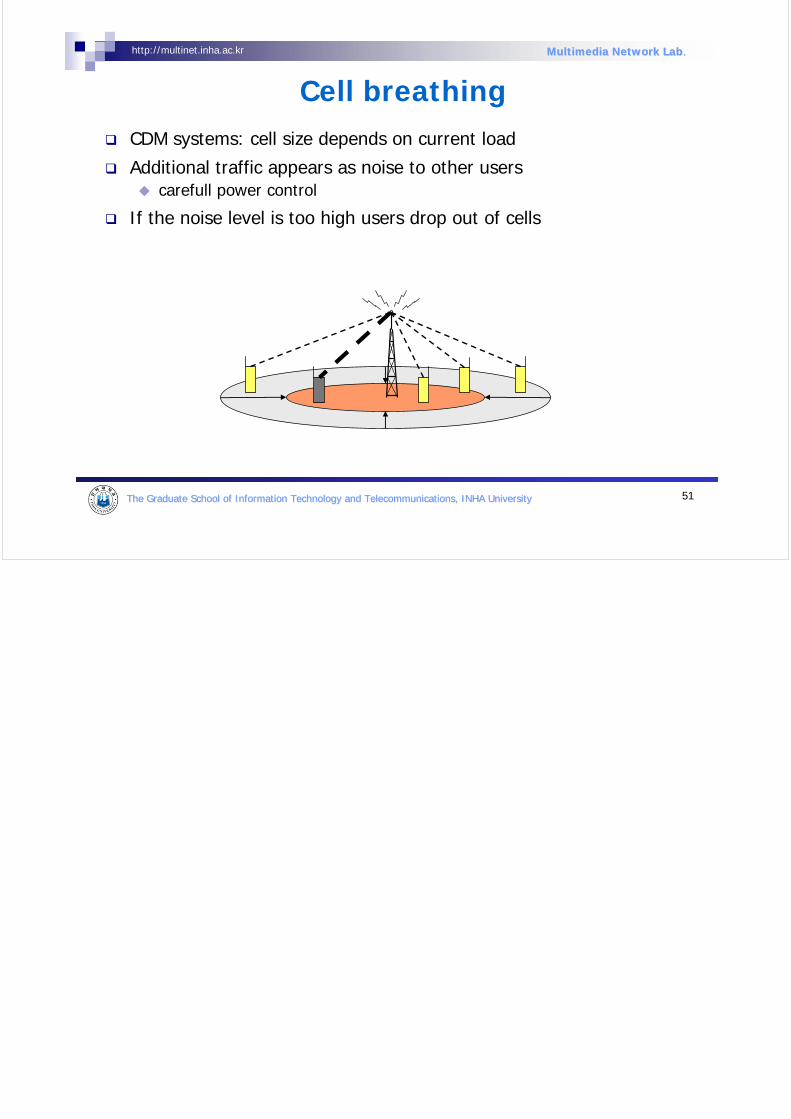
Cell breathingCDM systems: cell size depends on current load
Additional traffic appears as noise to other userscarefull power control
If the noise level is too high users drop out of cells