Embed Size (px)
Citation preview

NASA/TM-2004-212852
Mobile Aerial Tracking and Imaging System (MATrIS) for Aeronautical Research
Daniel W. BanksNASA Dryden Flight Research CenterEdwards, California
Robert C. BlanchardGeorge Washington UniversityWashington, District of Columbia
Geoffrey M. MillerPVP Advanced EO Systems, Inc.Orange, California
August 2004

The NASA STI Program Office…in Profile
Since its founding, NASA has been dedicatedto the advancement of aeronautics and space science. The NASA Scientific and Technical Information (STI) Program Office plays a keypart in helping NASA maintain thisimportant role.
The NASA STI Program Office is operated byLangley Research Center, the lead center forNASA’s scientific and technical information.The NASA STI Program Office provides access to the NASA STI Database, the largest collectionof aeronautical and space science STI in theworld. The Program Office is also NASA’s institutional mechanism for disseminating theresults of its research and development activities. These results are published by NASA in theNASA STI Report Series, which includes the following report types:
• TECHNICAL PUBLICATION. Reports of completed research or a major significantphase of research that present the results of NASA programs and include extensive dataor theoretical analysis. Includes compilations of significant scientific and technical data and information deemed to be of continuing reference value. NASA’s counterpart of peer-reviewed formal professional papers but has less stringent limitations on manuscriptlength and extent of graphic presentations.
• TECHNICAL MEMORANDUM. Scientificand technical findings that are preliminary orof specialized interest, e.g., quick releasereports, working papers, and bibliographiesthat contain minimal annotation. Does notcontain extensive analysis.
• CONTRACTOR REPORT. Scientific and technical findings by NASA-sponsored contractors and grantees.
• CONFERENCE PUBLICATION. Collected papers from scientific andtechnical conferences, symposia, seminars,or other meetings sponsored or cosponsoredby NASA.
• SPECIAL PUBLICATION. Scientific,technical, or historical information fromNASA programs, projects, and missions,often concerned with subjects havingsubstantial public interest.
• TECHNICAL TRANSLATION. English- language translations of foreign scientific and technical material pertinent toNASA’s mission.
Specialized services that complement the STIProgram Office’s diverse offerings include creating custom thesauri, building customizeddatabases, organizing and publishing researchresults…even providing videos.
For more information about the NASA STIProgram Office, see the following:
• Access the NASA STI Program Home Pageat
http://www.sti.nasa.gov
• E-mail your question via the Internet to [email protected]
• Fax your question to the NASA Access HelpDesk at (301) 621-0134
• Telephone the NASA Access Help Desk at(301) 621-0390
• Write to:NASA Access Help DeskNASA Center for AeroSpace Information7121 Standard DriveHanover, MD 21076-1320
NASA/TM-2004-212852
Mobile Aerial Tracking and Imaging System (MATrIS) for Aeronautical Research
Daniel W. BanksNASA Dryden Flight Research CenterEdwards, California
Robert C. BlanchardGeorge Washington UniversityWashington, District of Columbia
Geoffrey M. MillerPVP Advanced EO Systems, Inc.Orange, California
August 2004
National Aeronautics andSpace Administration
Dryden Flight Research CenterEdwards, California 93523-0273

NOTICE
Use of trade names or names of manufacturers in this document does not constitute an official endorsementof such products or manufacturers, either expressed or implied, by the National Aeronautics andSpace Administration.
Available from the following:
NASA Center for AeroSpace Information (CASI) National Technical Information Service (NTIS)7121 Standard Drive 5285 Port Royal RoadHanover, MD 21076-1320 Springfield, VA 22161-2171(301) 621-0390 (703) 487-4650
ABSTRACT
A mobile, rapidly deployable ground-based system to track and image targets of aeronautical interesthas been developed. Targets include reentering reusable launch vehicles as well as atmospheric andtransatmospheric vehicles. The optics were designed to image targets in the visible and infraredwavelengths. To minimize acquisition cost and development time, the system uses commerciallyavailable hardware and software where possible. The conception and initial funding of this systemoriginated with a study of ground-based imaging of global aerothermal characteristics of reusable launchvehicle configurations. During that study the National Aeronautics and Space Administration teamedwith the Missile Defense Agency/Innovative Science and Technology Experimentation Facility to testtechniques and analysis on two Space Shuttle flights.
NOMENCLATURE
f f/number (focal length/aperture)
FOV field of view, degrees
GPS global positioning system
IR infrared
ISAFE Infrared Sensing Aeroheating Flight Experiment
ISTEF Innovative Science and Technology Experimentation Facility
MATrIS Mobile Aerial Tracking and Imaging System
MDA Missile Defense Agency
freestream Mach number
MVSP motorized video surveillance platform
MWIR mid-wave infrared
NASA National Aeronautics and Space Administration
RA relative aperture
RLV reusable launch vehicle
TPS thermal protection system
emissivity
exit angle
INTRODUCTION
A primary design driver in any reentering spacecraft is the thermal protection system (TPS). Reusablelaunch vehicles (RLVs) need a robust and typically reusable TPS with minimum mass in order tomaximize performance and payload. Peak heating and exposure time near peak heating are key factors inTPS design. Hypersonic boundary-layer transition can cause peak heating to increase by a factor of twoor more. Thus, early boundary-layer transition can have a dramatic effect on peak heating, exposure nearpeak heating and, ultimately, TPS design. Because of unknowns in hypersonic boundary-layer transition,
M∞
ε
Θ'
2
added margins must be accounted for which lead to higher TPS mass and reduced RLV performance.While it is typical to attach some sensors to the windward surfaces (surfaces with highest heating), it isimpractical to populate much of the surface or to have sensors on many critical areas. Furthermore, thesensors and associated equipment add weight and reduce vehicle performance. Infrared (IR) imaging hasbeen used very successfully in the past to image and characterize boundary-layer transition and surfaceheating (refs. 1–3). Infrared imaging is global and nonintrusive, and in addition has the ability to showother flow features such as shock waves and some separated areas. Any flow phenomena that creates ameasurable temperature change can be imaged by IR.
In an effort to develop the techniques and methods to image reentering RLVs NASA teamed with theMissile Defense Agency/Innovative Science and Technology Experimentation Facility (MDA/ISTEF) inan effort called the Infrared Sensing Aeroheating Flight Experiment (ISAFE). Using ground-basedoptical systems developed by MDA (formerly BMDO, the Ballistic Missile Defense Organization) tworeentering Space Shuttle flights were imaged and analyzed. The results of the study (refs. 4, 5) were veryfavorable. The MDA equipment, however, while mobile, was difficult to rapidly deploy, had othercommitments, and was costly because of its other capabilities. NASA has been designing a system thatincorporates those capabilities that are needed for the reentry imaging but keeps the system very portable.The system uses commercially available components, where possible, to minimize cost and developmenttime. In addition, NASA had been developing IR systems to image other targets of aeronautical interest,notably transition on subsonic and supersonic aircraft wings (refs. 1–3). These systems included in situand remote airborne units. The design of this ground system would include the capability to image theseand other aeronautical targets where practical.
The Mobile Aerial Tracking and Imaging System (MATrIS) is currently capable of tracking objectseither optically or with global positioning system (GPS) data transmitted from the target. Infrared imagescan be recorded analog or digital, while simultaneously-captured visual wavelength images are recordedanalog. The main optics are a multi-spectral telescope with a Cassegrain focus, 12.5-inch (31.75 cm)main mirror, 300-inch (762 cm) focal length, f/24, with a field of view (FOV) of 0.06 degrees alsoconfigured as an f/12, 150-inch (381 cm) focal length with an FOV of 0.12 degrees. This is opticallyequivalent to the MDA/ISTEF 12.5-inch telescope used in the initial study. The unit utilizes a sharedaperture for mid-wave infrared (MWIR) and visible wavelength cameras. The gimbal is capable ofazimuth velocity from < 0.1 to 100 deg/sec, elevation velocity from < 0.1 to 60 deg/sec, azimuthacceleration to 100 deg/sec
2
,
elevation acceleration to 60 deg/sec
2
, micro-step position control, andfour-microradian step resolution.
This report will present the development and design of, and the results from, the system.
BACKGROUND
This section will discuss the technical background, past experimental results, and the development ofthe tracking and imaging system.
Windward Reusable Launch Vehicle Aerothermal Measurements
The study of windward aerothermal characteristics of RLVs or any reentering vehicle is of vitalinterest to designers of these vehicles. The TPS is a major design constraint of any reentering vehicle.
3
Understanding the characteristics of the aeroheating and, specifically, the hypersonic boundary layer attransition can lead to more effective TPS design. Infrared thermography, which measures the thermalradiance of an object, is a useful technique to determine boundary-layer transition and surfacetemperature, as well as other flow phenomena. The principle of IR thermography is that all bodies with atemperature above absolute zero continuously emit, absorb, and reflect radiation in a characteristicmanner. The emission intensity peaks at shorter wavelengths for higher temperatures and at longerwavelengths (for example, IR) for lower temperatures. At a given wavelength the emission intensity alsotypically increases with temperature. The intensity of the image of such an object also varies with otherfactors such as target surface emissivity (
ε
), path transmittance, and atmospheric radiance. Withsufficient calibration, the IR intensity can be related back to an accurate surface temperature. Ifindependent in situ surface temperature measurements are available the process is much simpler andmore accurate. These in situ measurements serve as benchmarks for the rest of the image and thus, manyof the aforementioned factors can be neglected. Blanchard et. al. (ref. 5) details the image-processingtechniques and subsequent data analysis for both methods.
NASA/Missile Defense Agency Infrared Sensing Aeroheating Flight Experiment
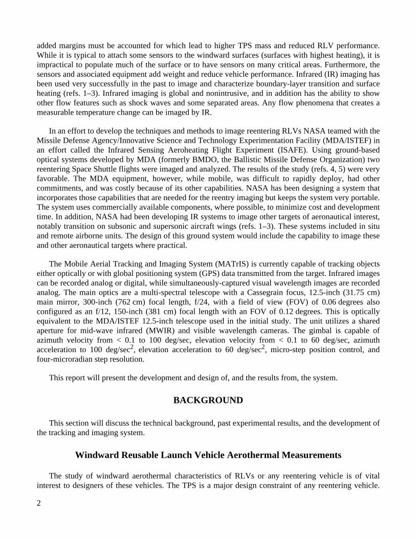
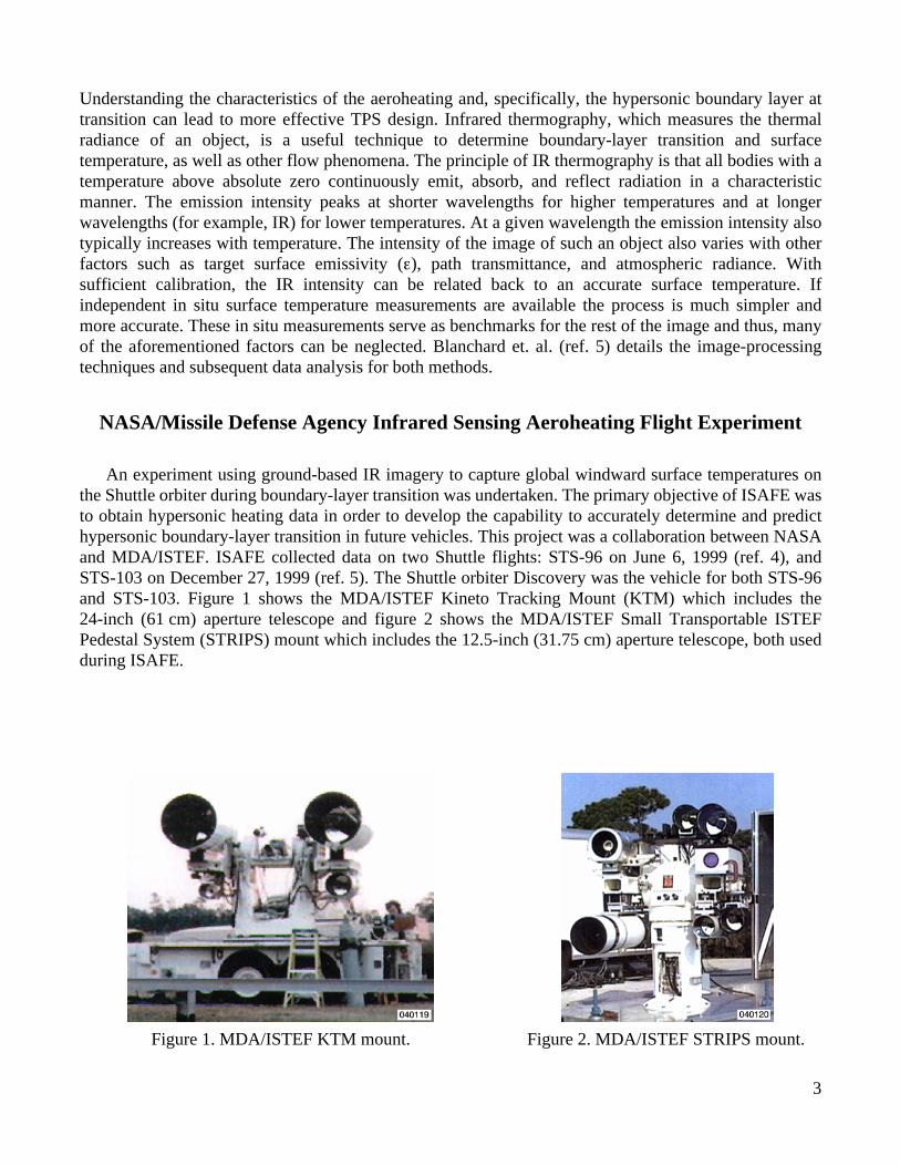
An experiment using ground-based IR imagery to capture global windward surface temperatures onthe Shuttle orbiter during boundary-layer transition was undertaken. The primary objective of ISAFE wasto obtain hypersonic heating data in order to develop the capability to accurately determine and predicthypersonic boundary-layer transition in future vehicles. This project was a collaboration between NASAand MDA/ISTEF. ISAFE collected data on two Shuttle flights: STS-96 on June 6, 1999 (ref. 4), andSTS-103 on December 27, 1999 (ref. 5). The Shuttle orbiter Discovery was the vehicle for both STS-96and STS-103. Figure 1 shows the MDA/ISTEF Kineto Tracking Mount (KTM) which includes the24-inch (61 cm) aperture telescope and figure 2 shows the MDA/ISTEF Small Transportable ISTEFPedestal System (STRIPS) mount which includes the 12.5-inch (31.75 cm) aperture telescope, both usedduring ISAFE.
Figure 1. MDA/ISTEF KTM mount. Figure 2. MDA/ISTEF STRIPS mount.
4
STS-96 Results
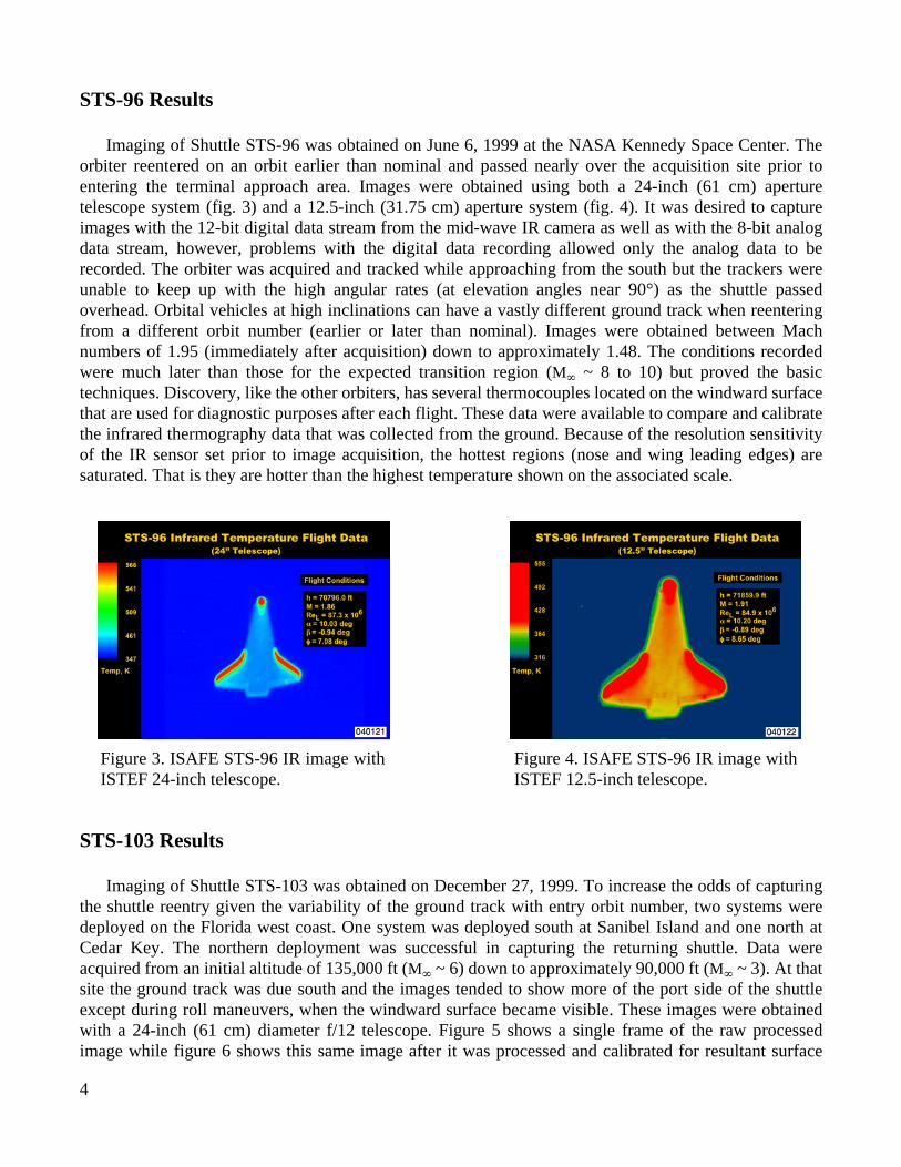
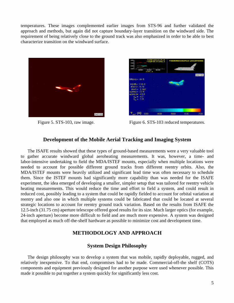
Imaging of Shuttle STS-96 was obtained on June 6, 1999 at the NASA Kennedy Space Center. Theorbiter reentered on an orbit earlier than nominal and passed nearly over the acquisition site prior toentering the terminal approach area. Images were obtained using both a 24-inch (61 cm) aperturetelescope system (fig. 3) and a 12.5-inch (31.75 cm) aperture system (fig. 4). It was desired to captureimages with the 12-bit digital data stream from the mid-wave IR camera as well as with the 8-bit analogdata stream, however, problems with the digital data recording allowed only the analog data to berecorded. The orbiter was acquired and tracked while approaching from the south but the trackers wereunable to keep up with the high angular rates (at elevation angles near 90°) as the shuttle passedoverhead. Orbital vehicles at high inclinations can have a vastly different ground track when reenteringfrom a different orbit number (earlier or later than nominal). Images were obtained between Machnumbers of 1.95 (immediately after acquisition) down to approximately 1.48. The conditions recordedwere much later than those for the expected transition region (
M
∞
~ 8 to 10) but proved the basictechniques. Discovery, like the other orbiters, has several thermocouples located on the windward surfacethat are used for diagnostic purposes after each flight. These data were available to compare and calibratethe infrared thermography data that was collected from the ground. Because of the resolution sensitivityof the IR sensor set prior to image acquisition, the hottest regions (nose and wing leading edges) aresaturated. That is they are hotter than the highest temperature shown on the associated scale.
STS-103 Results
Imaging of Shuttle STS-103 was obtained on December 27, 1999. To increase the odds of capturingthe shuttle reentry given the variability of the ground track with entry orbit number, two systems weredeployed on the Florida west coast. One system was deployed south at Sanibel Island and one north atCedar Key. The northern deployment was successful in capturing the returning shuttle. Data wereacquired from an initial altitude of 135,000 ft (
M
∞
~ 6) down to approximately 90,000 ft (
M
∞
~ 3). At thatsite the ground track was due south and the images tended to show more of the port side of the shuttleexcept during roll maneuvers, when the windward surface became visible. These images were obtainedwith a 24-inch (61 cm) diameter f/12 telescope. Figure 5 shows a single frame of the raw processedimage while figure 6 shows this same image after it was processed and calibrated for resultant surface
Figure 3. ISAFE STS-96 IR image withISTEF 24-inch telescope.
Figure 4. ISAFE STS-96 IR image withISTEF 12.5-inch telescope.
5
temperatures. These images complemented earlier images from STS-96 and further validated theapproach and methods, but again did not capture boundary-layer transition on the windward side. Therequirement of being relatively close to the ground track was also emphasized in order to be able to bestcharacterize transition on the windward surface.
Development of the Mobile Aerial Tracking and Imaging System
The ISAFE results showed that these types of ground-based measurements were a very valuable toolto gather accurate windward global aeroheating measurements. It was, however, a time- andlabor-intensive undertaking to field the MDA/ISTEF mounts, especially when multiple locations wereneeded to account for possible different ground tracks from different reentry orbits. Also, theMDA/ISTEF mounts were heavily utilized and significant lead time was often necessary to schedulethem. Since the ISTEF mounts had significantly more capability than was needed for the ISAFEexperiment, the idea emerged of developing a smaller, simpler setup that was tailored for reentry vehicleheating measurements. This would reduce the time and effort to field a system, and could result inreduced cost, possibly leading to a system that could be rapidly fielded to account for orbital variation atreentry and also one in which multiple systems could be fabricated that could be located at severalstrategic locations to account for reentry ground track variation. Based on the results from ISAFE the12.5-inch (31.75 cm) aperture telescope offered good results for its size. Much larger optics (for example,24-inch aperture) become more difficult to field and are much more expensive. A system was designedthat employed as much off-the-shelf hardware as possible to minimize cost and development time.
METHODOLOGY AND APPROACH
System Design Philosophy
The design philosophy was to develop a system that was mobile, rapidly deployable, rugged, andrelatively inexpensive. To that end, compromises had to be made. Commercial-off-the shelf (COTS)components and equipment previously designed for another purpose were used whenever possible. Thismade it possible to put together a system quickly for significantly less cost.
Figure 5. STS-103, raw image. Figure 6. STS-103 reduced temperatures.
6
System Design
The MATrIS design hardware consists of:
• main narrow FOV optical telescope (300-inch and 150-inch focal length configurations)
• optical platform to accept a variety of medium-sized optics (mission-specific)
• wide FOV zoom-capable finder/tracking telescope
• gimbal mounting platform
• optical tracker
• GPS tracker
• gimbal/tracker interface
• analog and digital recording systems
System Description
Optics
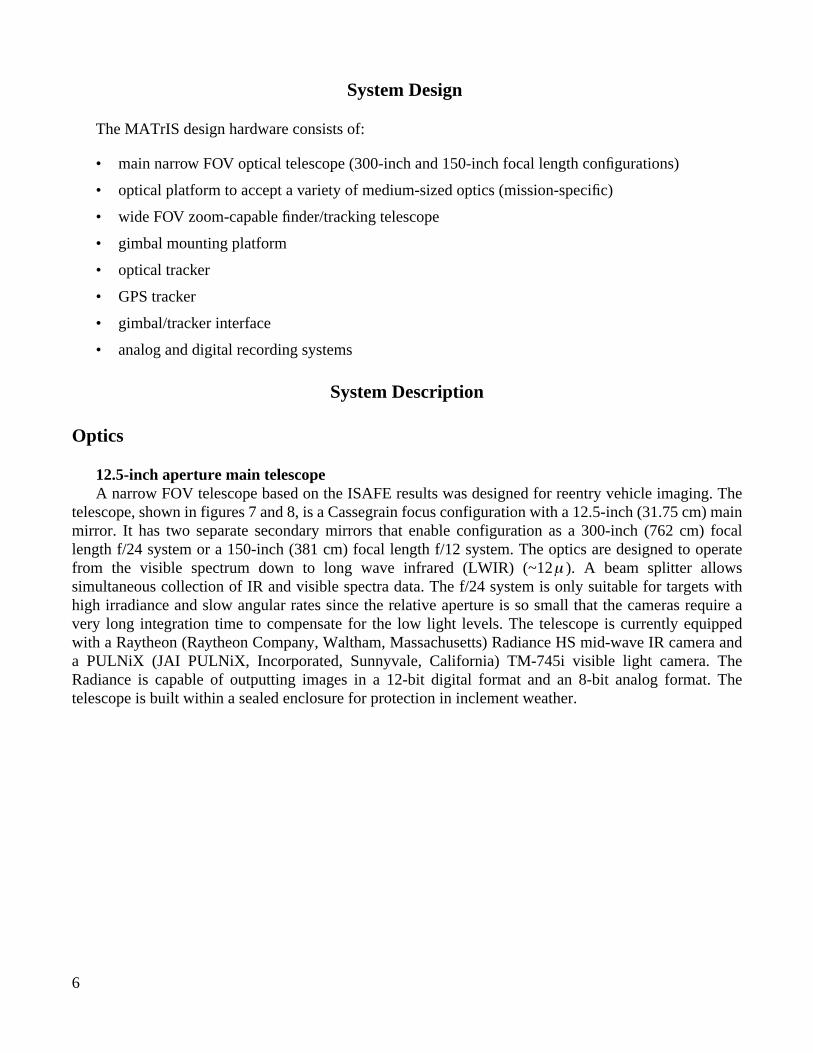
12.5-inch aperture main telescope
A narrow FOV telescope based on the ISAFE results was designed for reentry vehicle imaging. Thetelescope, shown in figures 7 and 8, is a Cassegrain focus configuration with a 12.5-inch (31.75 cm) mainmirror. It has two separate secondary mirrors that enable configuration as a 300-inch (762 cm) focallength f/24 system or a 150-inch (381 cm) focal length f/12 system. The optics are designed to operatefrom the visible spectrum down to long wave infrared (LWIR) (~12 ). A beam splitter allowssimultaneous collection of IR and visible spectra data. The f/24 system is only suitable for targets withhigh irradiance and slow angular rates since the relative aperture is so small that the cameras require avery long integration time to compensate for the low light levels. The telescope is currently equippedwith a Raytheon (Raytheon Company, Waltham, Massachusetts) Radiance HS mid-wave IR camera anda PULNiX (JAI PULNiX, Incorporated, Sunnyvale, California) TM-745i visible light camera. TheRadiance is capable of outputting images in a 12-bit digital format and an 8-bit analog format. Thetelescope is built within a sealed enclosure for protection in inclement weather.
µ
7
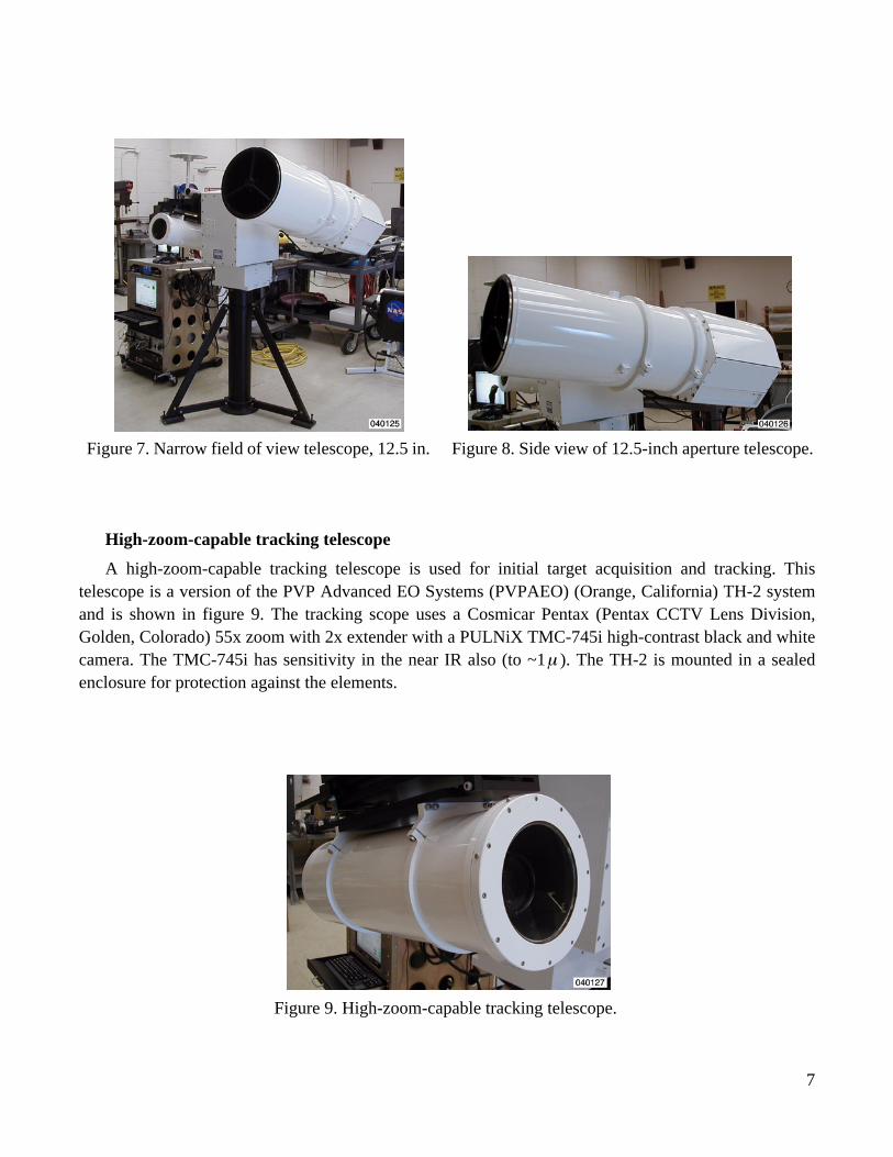
High-zoom-capable tracking telescope
A high-zoom-capable tracking telescope is used for initial target acquisition and tracking. Thistelescope is a version of the PVP Advanced EO Systems (PVPAEO) (Orange, California) TH-2 systemand is shown in figure 9. The tracking scope uses a Cosmicar Pentax (Pentax CCTV Lens Division,Golden, Colorado) 55x zoom with 2x extender with a PULNiX TMC-745i high-contrast black and whitecamera. The TMC-745i has sensitivity in the near IR also (to ~1 ). The TH-2 is mounted in a sealedenclosure for protection against the elements.
Figure 7. Narrow field of view telescope, 12.5 in. Figure 8. Side view of 12.5-inch aperture telescope.
µ
Figure 9. High-zoom-capable tracking telescope.
8
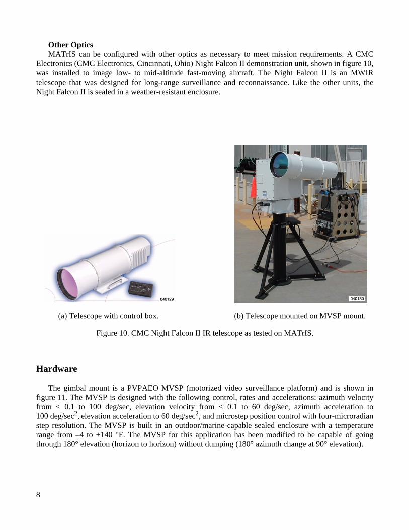
Other Optics
MATrIS can be configured with other optics as necessary to meet mission requirements. A CMCElectronics (CMC Electronics, Cincinnati, Ohio) Night Falcon II demonstration unit, shown in figure 10,was installed to image low- to mid-altitude fast-moving aircraft. The Night Falcon II is an MWIRtelescope that was designed for long-range surveillance and reconnaissance. Like the other units, theNight Falcon II is sealed in a weather-resistant enclosure.
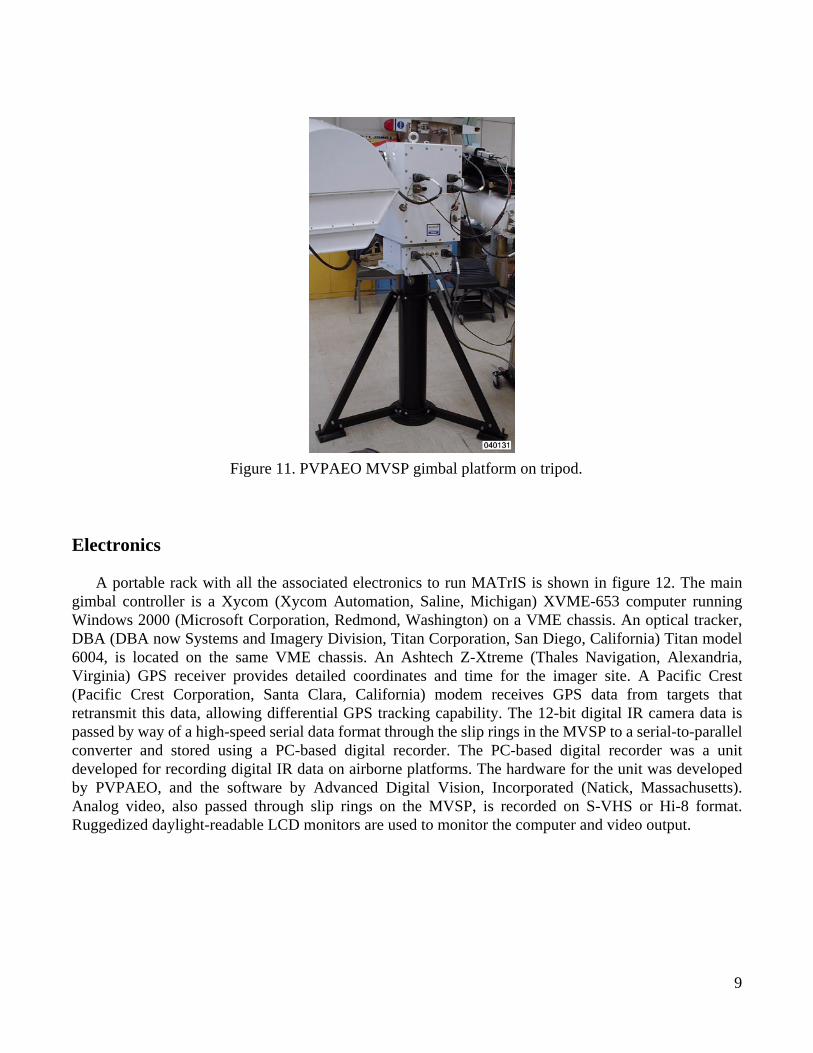
Hardware
The gimbal mount is a PVPAEO MVSP (motorized video surveillance platform) and is shown infigure 11. The MVSP is designed with the following control, rates and accelerations: azimuth velocityfrom < 0.1 to 100 deg/sec, elevation velocity from < 0.1 to 60 deg/sec, azimuth acceleration to100 deg/sec
2
,
elevation acceleration to 60 deg/sec
2
, and microstep position control with four-microradianstep resolution. The MVSP is built in an outdoor/marine-capable sealed enclosure with a temperaturerange from –4 to +140 °F. The MVSP for this application has been modified to be capable of goingthrough 180° elevation (horizon to horizon) without dumping (180° azimuth change at 90° elevation).
Figure 10. CMC Night Falcon II IR telescope as tested on MATrIS.
(a) Telescope with control box. (b) Telescope mounted on MVSP mount.
9
Electronics
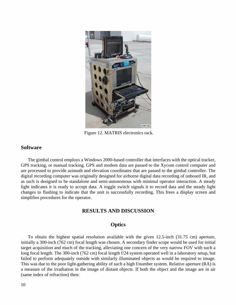
A portable rack with all the associated electronics to run MATrIS is shown in figure 12. The maingimbal controller is a Xycom (Xycom Automation, Saline, Michigan) XVME-653 computer runningWindows 2000 (Microsoft Corporation, Redmond, Washington) on a VME chassis. An optical tracker,DBA (DBA now Systems and Imagery Division, Titan Corporation, San Diego, California) Titan model6004, is located on the same VME chassis. An Ashtech Z-Xtreme (Thales Navigation, Alexandria,Virginia) GPS receiver provides detailed coordinates and time for the imager site. A Pacific Crest(Pacific Crest Corporation, Santa Clara, California) modem receives GPS data from targets thatretransmit this data, allowing differential GPS tracking capability. The 12-bit digital IR camera data ispassed by way of a high-speed serial data format through the slip rings in the MVSP to a serial-to-parallelconverter and stored using a PC-based digital recorder. The PC-based digital recorder was a unitdeveloped for recording digital IR data on airborne platforms. The hardware for the unit was developedby PVPAEO, and the software by Advanced Digital Vision, Incorporated (Natick, Massachusetts).Analog video, also passed through slip rings on the MVSP, is recorded on S-VHS or Hi-8 format.Ruggedized daylight-readable LCD monitors are used to monitor the computer and video output.
Figure 11. PVPAEO MVSP gimbal platform on tripod.
10
Software
The gimbal control employs a Windows 2000-based controller that interfaces with the optical tracker,GPS tracking, or manual tracking. GPS and modem data are passed to the Xycom control computer andare processed to provide azimuth and elevation coordinates that are passed to the gimbal controller. Thedigital recording computer was originally designed for airborne digital data recording of onboard IR, andas such is designed to be standalone and semi-autonomous with minimal operator interaction. A steadylight indicates it is ready to accept data. A toggle switch signals it to record data and the steady lightchanges to flashing to indicate that the unit is successfully recording. This frees a display screen andsimplifies procedures for the operator.
RESULTS AND DISCUSSION
Optics
To obtain the highest spatial resolution available with the given 12.5-inch (31.75 cm) aperture,initially a 300-inch (762 cm) focal length was chosen. A secondary finder scope would be used for initialtarget acquisition and much of the tracking, alleviating one concern of the very narrow FOV with such along focal length. The 300-inch (762 cm) focal length f/24 system operated well in a laboratory setup, butfailed to perform adequately outside with similarly illuminated objects as would be required to image.This was due to the poor light-gathering ability of such a high f/number system. Relative aperture (RA) isa measure of the irradiation in the image of distant objects. If both the object and the image are in air(same index of refraction) then:
Figure 12. MATRIS electronics rack.
11
( = exit angle) (1)
or (where N = f/number) (2)
So, for a given optical system and object, the intensity of the image is a function of the f/number(ref. 6). Without very bright, high-contrast targets a very long integration time is necessary with thesensor. The integration time necessary is precluded by the inability of the tracker to hold still a target withany appreciable angular rate in the very narrow FOV. The apparent motion of these targets and longintegration times causes an unacceptable blurring of the image. The requirement to image targets of lowerintensity and/or faster angular rates necessitates a shorter focal length system. An alternate secondarymirror configuration was designed that reduces the focal length to 150 inches (381 cm) and f/12. Thisincreases the light-gathering ability and will reduce the motion-based blur of faster moving targets. The12.5-inch (31.75 cm) telescope used during the ISAFE program was also dual-configured as a 300-inch(762 cm) f/24 and a 150-inch (381 cm) f/12 system.
The finder scope (a modified PVPAEO TH-2) is used for target acquisition and most of the opticaltracking tasks. The ability to rapidly move between a wide FOV (acquisition) and narrow FOV (tracking)is necessary to successfully acquire and smoothly track targets.
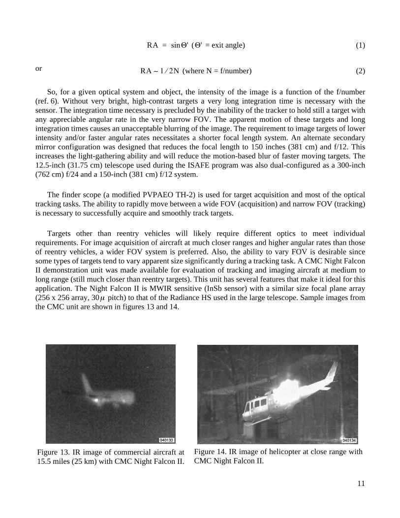
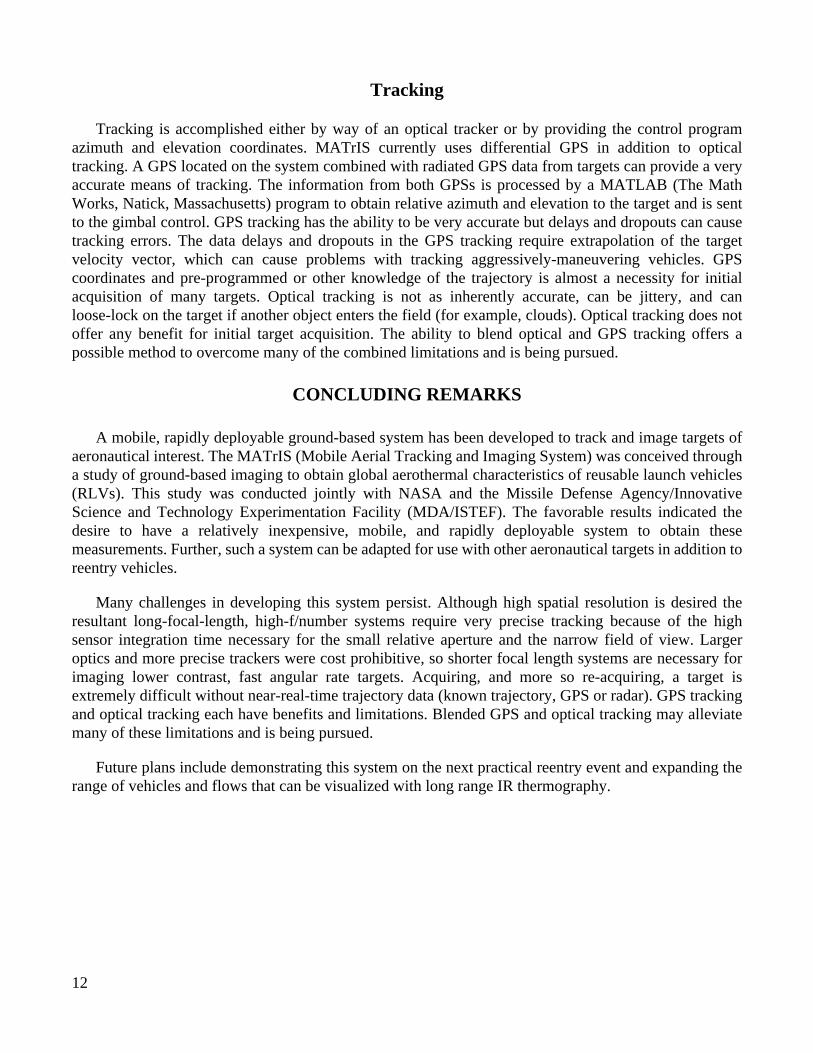
Targets other than reentry vehicles will likely require different optics to meet individualrequirements. For image acquisition of aircraft at much closer ranges and higher angular rates than thoseof reentry vehicles, a wider FOV system is preferred. Also, the ability to vary FOV is desirable sincesome types of targets tend to vary apparent size significantly during a tracking task. A CMC Night FalconII demonstration unit was made available for evaluation of tracking and imaging aircraft at medium tolong range (still much closer than reentry targets). This unit has several features that make it ideal for thisapplication. The Night Falcon II is MWIR sensitive (InSb sensor) with a similar size focal plane array(256 x 256 array, 30 pitch) to that of the Radiance HS used in the large telescope. Sample images fromthe CMC unit are shown in figures 13 and 14.
RA Θ'sin= Θ'
RA 1 2⁄ N∼
µ
Figure 13. IR image of commercial aircraft at15.5 miles (25 km) with CMC Night Falcon II.
Figure 14. IR image of helicopter at close range withCMC Night Falcon II.
12
Tracking
Tracking is accomplished either by way of an optical tracker or by providing the control programazimuth and elevation coordinates. MATrIS currently uses differential GPS in addition to opticaltracking. A GPS located on the system combined with radiated GPS data from targets can provide a veryaccurate means of tracking. The information from both GPSs is processed by a MATLAB (The MathWorks, Natick, Massachusetts) program to obtain relative azimuth and elevation to the target and is sentto the gimbal control. GPS tracking has the ability to be very accurate but delays and dropouts can causetracking errors. The data delays and dropouts in the GPS tracking require extrapolation of the targetvelocity vector, which can cause problems with tracking aggressively-maneuvering vehicles. GPScoordinates and pre-programmed or other knowledge of the trajectory is almost a necessity for initialacquisition of many targets. Optical tracking is not as inherently accurate, can be jittery, and canloose-lock on the target if another object enters the field (for example, clouds). Optical tracking does notoffer any benefit for initial target acquisition. The ability to blend optical and GPS tracking offers apossible method to overcome many of the combined limitations and is being pursued.
CONCLUDING REMARKS
A mobile, rapidly deployable ground-based system has been developed to track and image targets ofaeronautical interest. The MATrIS (Mobile Aerial Tracking and Imaging System) was conceived througha study of ground-based imaging to obtain global aerothermal characteristics of reusable launch vehicles(RLVs). This study was conducted jointly with NASA and the Missile Defense Agency/InnovativeScience and Technology Experimentation Facility (MDA/ISTEF). The favorable results indicated thedesire to have a relatively inexpensive, mobile, and rapidly deployable system to obtain thesemeasurements. Further, such a system can be adapted for use with other aeronautical targets in addition toreentry vehicles.
Many challenges in developing this system persist. Although high spatial resolution is desired theresultant long-focal-length, high-f/number systems require very precise tracking because of the highsensor integration time necessary for the small relative aperture and the narrow field of view. Largeroptics and more precise trackers were cost prohibitive, so shorter focal length systems are necessary forimaging lower contrast, fast angular rate targets. Acquiring, and more so re-acquiring, a target isextremely difficult without near-real-time trajectory data (known trajectory, GPS or radar). GPS trackingand optical tracking each have benefits and limitations. Blended GPS and optical tracking may alleviatemany of these limitations and is being pursued.
Future plans include demonstrating this system on the next practical reentry event and expanding therange of vehicles and flows that can be visualized with long range IR thermography.

13
REFERENCES
1. van Dam, C. P., H. J. Shiu, and D. W. Banks,
In-Flight Flow Visualization Using InfraredThermography,
NASA CR-97-207087, 1997.
2. van Dam, C. P., H. J. Shiu, and D. W. Banks, “Remote In-Flight Boundary Layer TransitionVisualization Using Infrared Thermography,” paper 181,
Proceedings of the 8
th
InternationalSymposium on Flow Visualization
, 1998.
3. Banks, D. W., C. P. van Dam, H. J. Shiu, and G. M. Miller,
Visualization of In-Flight FlowPhenomena Using Infrared Thermography
, NASA/TM-2000-209027, 2000.
4. Blanchard, Robert C., Richard G. Wilmoth, Christopher E. Glass, N. Ronald Merski, Scott A. Berry,Timothy J. Bozung, Alan Tietjen, Jodean Wendt, and Don Dawson, “Infrared Sensing AeroheatingFlight Experiment: STS-96 Flight Results,” AIAA
0352, January 2001.
5. Blanchard, R. C., B. P. Anderson, S. S. Welch, C. Glass, S. A. Berry, N. R. Merski, D. W. Banks,A. Tietjen, and M. Lovern, “Shuttle Orbiter Fuselage Global Temperature Measurements fromInfrared Images at Hypersonic Speeds,” AIAA
4702, August 2002.
6. Jamieson, John A., Raymond H. McFee, Gilbert N. Plass, Robert H. Grube, and Robert G. Richards,
Infrared Physics and Engineering,
McGraw-Hill Publishing, 1963.
REPORT DOCUMENTATION PAGE
Form ApprovedOMB No. 0704-0188
Public reporting burden for this collection of information is estimated to average 1 hour per response, including the time for reviewing instructions, searching existing data sources, gathering andmaintaining the data needed, and completing and reviewing the collection of information. Send comments regarding this burden estimate or any other aspect of this collection of information,including suggestions for reducing this burden, to Washington Headquarters Services, Directorate for Information Operations and Reports, 1215 Jefferson Davis Highway, Suite 1204, Arlington,VA 22202-4302, and to the Office of Management and Budget, Paperwork Reduction Project (0704-0188), Washington, DC 20503.
1. AGENCY USE ONLY (Leave blank) 2. REPORT DATE 3. REPORT TYPE AND DATES COVERED
4. TITLE AND SUBTITLE 5. FUNDING NUMBERS
6. AUTHOR(S)
8. PERFORMING ORGANIZATION REPORT NUMBER
7. PERFORMING ORGANIZATION NAME(S) AND ADDRESS(ES)
9. SPONSORING/MONITORING AGENCY NAME(S) AND ADDRESS(ES) 10. SPONSORING/MONITORING AGENCY REPORT NUMBER
11. SUPPLEMENTARY NOTES
12a. DISTRIBUTION/AVAILABILITY STATEMENT 12b. DISTRIBUTION CODE
13. ABSTRACT (Maximum 200 words)
14. SUBJECT TERMS 15. NUMBER OF PAGES
16. PRICE CODE
17. SECURITY CLASSIFICATION OF REPORT
18. SECURITY CLASSIFICATION OF THIS PAGE
19. SECURITY CLASSIFICATION OF ABSTRACT
20. LIMITATION OF ABSTRACT
NSN 7540-01-280-5500 Standard Form 298 (Rev. 2-89)
Prescribed by ANSI Std. Z39-18298-102
Mobile Aerial Tracking and Imaging System (MATrIS) for AeronauticalResearch
090-20-00-GA-XR-00-SLE
Daniel W. Banks, Robert C. Blanchard, and Geoffrey M. Miller
NASA Dryden Flight Research CenterP.O. Box 273Edwards, California 93523-0273
H-2561
National Aeronautics and Space AdministrationWashington, DC 20546-0001 NASA/TM-2004-212852
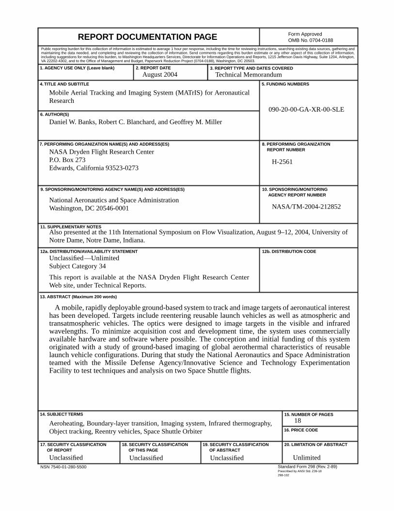
A mobile, rapidly deployable ground-based system to track and image targets of aeronautical interesthas been developed. Targets include reentering reusable launch vehicles as well as atmospheric andtransatmospheric vehicles. The optics were designed to image targets in the visible and infraredwavelengths. To minimize acquisition cost and development time, the system uses commerciallyavailable hardware and software where possible. The conception and initial funding of this systemoriginated with a study of ground-based imaging of global aerothermal characteristics of reusablelaunch vehicle configurations. During that study the National Aeronautics and Space Administrationteamed with the Missile Defense Agency/Innovative Science and Technology ExperimentationFacility to test techniques and analysis on two Space Shuttle flights.
Aeroheating, Boundary-layer transition, Imaging system, Infrared thermography,Object tracking, Reentry vehicles, Space Shuttle Orbiter
18
Unclassified Unclassified Unclassified Unlimited
August 2004 Technical Memorandum
Also presented at the 11th International Symposium on Flow Visualization, August 9–12, 2004, University ofNotre Dame, Notre Dame, Indiana.
Unclassified—UnlimitedSubject Category 34
This report is available at the NASA Dryden Flight Research CenterWeb site, under Technical Reports.