Embed Size (px)
Citation preview
NTNU Trondheim Norwegian University of Science and Technology Department of Marine Technology
Page 1 of 22
PROPOSED TOPICS
for
PROJECT/M.SC.THESES 2013-14
with emphasis on offshore wind turbines (and offshore oil and gas platforms)
Torgeir Moan Professor, Director
Centre for Ships and Ocean Structures
Email: [email protected] Tel.: +47 73 59 5541/ Mob: +47 95050791
Draft 01.04.2013
NTNU Department of Marine Technology Norwegian University of Science and Technology
Page 2 of 22
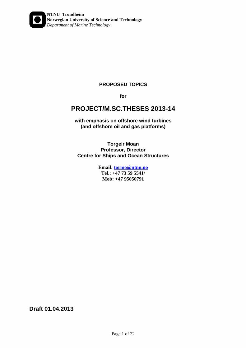
MARINE STRUCTURES AND OPERATIONS
Guideance In the present proposal of topics for project and MSc theses, the emphasis is on offshore wind turbines, but oil and gas platforms are also referred to because of the similarity of the mentioned types of systems, and hence the technology transfer between these to fields of engineering.. Some indications on project themes are given. However, since the offshore track in EWEM will involve project work in the fall, the details regarding the MSc thesis for the spring of 2014 might be discussed in the fall of 2013. Supervisors of the proposed topics will be a team : - Professor T.Moan; Assoc. adjunct professor Zhen Gao,
postdoctors C. Michailides; A. Nematbakhsh; X.Ren; X.Ye; and PhD candidates E.Bachynski; J. de Vaal; Z. Jiang; M.Kvittem; L.Li; Q.Li; C.Luan; A.Nejad; and posssibly other researchers;
- Oil and gas…. Renewable energy - Transport - Seafood Infrastructure

NTNU Department of Marine Technology Norwegian University of Science and Technology
Page 3 of 22
BACKGROUND STRUCTURAL DESIGN
NTNU Department of Marine Technology Norwegian University of Science and Technology
Page 4 of 22
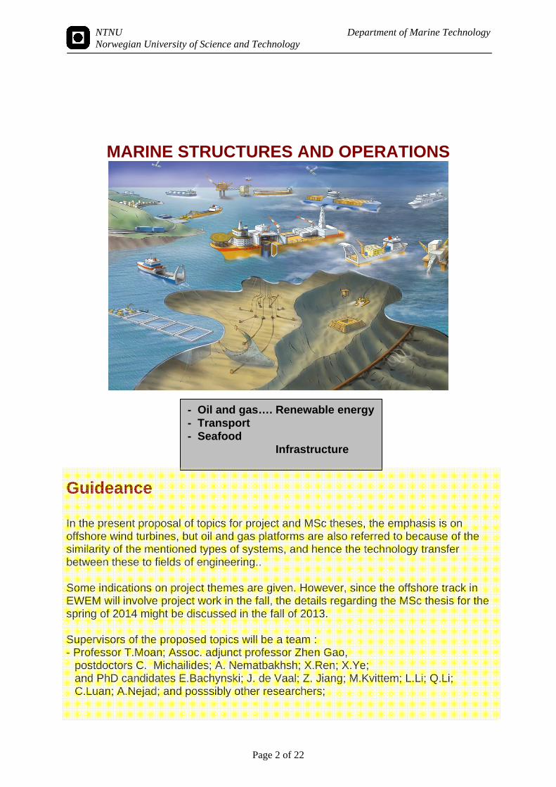
MARINE OPERATIONS Overview
Safety of marine operations
NTNU Department of Marine Technology Norwegian University of Science and Technology
Page 5 of 22
Basic Disciplines (one or more discipline may be relevant) Finite element method (FEM) for:
- stress analysis (by SESAM, .....) - ultimate strength analysis (by ABAQUS) Hydrodynamic and aerodynamic load effect analysis - FE analysis Ultimate strength - fabrication analysis Fatigue strength Reliability and risk analysis (analysis of uncertainty) probabilistic response analysis inspection planning as well as - sea and wind loads - load statistics - marine operations
Applications floating platforms (hydrodyn. loads, fatigue, ultimate strength, FEM, reliability analyses,
inspection) wave and offshore wind energy plants
Plan Depending upon your interest, the project - MSc. thesis can be: theoretical - relating to current research activity practical, of the same character as the work in DNV, engineering company, yard or other
industry company project work - summer job - MSc. thesis should preferably be seen as a sequence supervision by T. Moan and his research group and personnel from industry
Contacts with industry... DNV and other classification societies Aker Kværner,(Oslo, Bergen, Stavanger), Offshore Design (Oslo), ABB, APL (Arendal),
Vetco etc Oil companies Research institutes Foreign institutions (universities, research institutes, industry, ...) Recommendation In general it is recommended that the project and MSc thesis is based on methods (software) that have a broad application range.
NTNU Department of Marine Technology Norwegian University of Science and Technology
Page 6 of 22
WAVE- AND WIND-INDUCED RESPONSE ANALYSIS FOR DESIGN OF PLATFORMS OR WAVE- or WIND ENERGY CONVERTERS ; EVEN COMBINED WIND TURBINES AND WAVE ENERGY CONVERTERS Background
- wave loading represents the most important loading on marine structures, especially floating structures
- wave loads are stochastic in nature and depends on wave conditions which vary in intensity and direction over a long-term period and may be affected by nonlinearities
- wave loads may be amplified by structural dynamic effects - load effects for design should be determined to fit the relevant design criterion.
Hence, load effects for ultimate strength design should correspond to a defined annual probability of exceedance (or return period)
Aim
- carry out an analysis of loads to yield the proper load effects for design - obtain results for a specific case - wave-induced motions for assessment of operational safety
Methods
- Hydrodynamic analysis. Wave loads obtained by relevant method (usually available form existing software)
- structural modelling (possibly FEM) - stochastic analysis
Applications
- Floating production platforms - High speed vessels - Production ships - Floating airport or bridge
Co-operation
- Marine hydrodynamics, NTNU - MARINTEK, SINTEF Fishery and Aquaculture - DNV, ABB, Aker, Kværner, Offshore Design, Umoe - Evolving industries: renewable energy and sea food - dr.students, post doc fellows
Examples of topics
- design load effects for semi-submersibles - slamming response - stochastic nonlinear wave response - fatigue load effect analysis of platforms and wind turbines - extreme and fatigue load effects due to sloshing in LNG tanks
WIND POWER
NTNU Department of Marine Technology Norwegian University of Science and Technology
Page 7 of 22
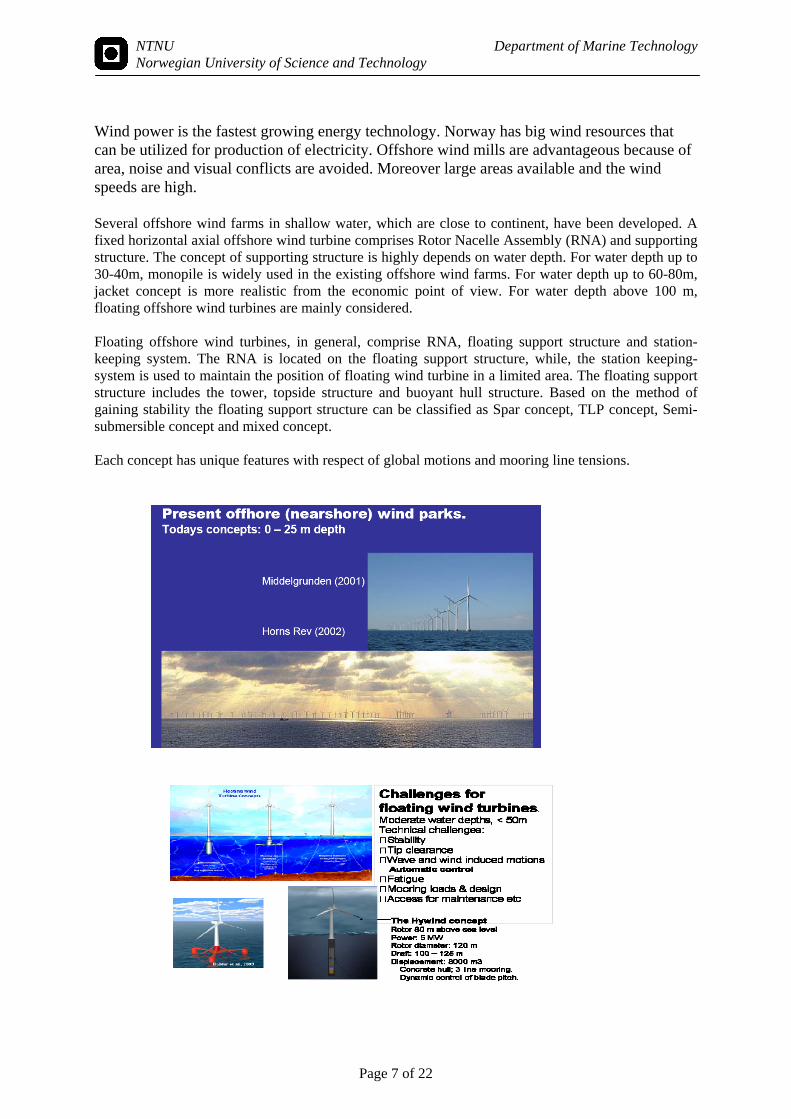
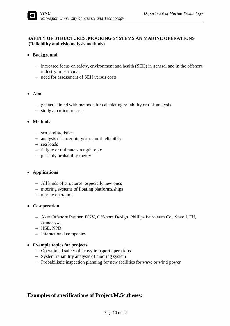
Wind power is the fastest growing energy technology. Norway has big wind resources that can be utilized for production of electricity. Offshore wind mills are advantageous because of area, noise and visual conflicts are avoided. Moreover large areas available and the wind speeds are high. Several offshore wind farms in shallow water, which are close to continent, have been developed. A fixed horizontal axial offshore wind turbine comprises Rotor Nacelle Assembly (RNA) and supporting structure. The concept of supporting structure is highly depends on water depth. For water depth up to 30-40m, monopile is widely used in the existing offshore wind farms. For water depth up to 60-80m, jacket concept is more realistic from the economic point of view. For water depth above 100 m, floating offshore wind turbines are mainly considered. Floating offshore wind turbines, in general, comprise RNA, floating support structure and station-keeping system. The RNA is located on the floating support structure, while, the station keeping-system is used to maintain the position of floating wind turbine in a limited area. The floating support structure includes the tower, topside structure and buoyant hull structure. Based on the method of gaining stability the floating support structure can be classified as Spar concept, TLP concept, Semi-submersible concept and mixed concept. Each concept has unique features with respect of global motions and mooring line tensions.

NTNU Department of Marine Technology Norwegian University of Science and Technology
Page 8 of 22
The focus will be on dynamic modelling of both bottom fixed and floating wind turbines. It might also be an opportunity to compare the numerical simulations of floating wind turbines with model test results. STRUCTURAL ANALYSIS BY FEM Background
finite element methods are the dominant method for structural analysis. Virtually all structural engineers would have to carry out such analyses. Linear analysis is carried out by e.g. SESAM. Nonlinear analysis, accounting for large deformations and plasticity up to ultimate collapse are carried out by the general purpose program ABAQUS
finite element analysis may be used to determine global response and local response for fatigue design check (response analyses) or the structural behaviour up to collapse including material and fabrication features (ultimate strength)
hydroelastic analysis (involving hydrodynamics and structural mechanics). Particularly important to - undertand the FEM by convergence studies etc and - apply FEM to new types of structures! - including large cruise and container vessels Aim
achieve experience with modelling , analysis with computer program SESAM obtain results for a specific case (e.g. global stress, ultimate strength)
Methods
FEM ; and may be Hydrodynamics in case of global analysis Stochastic analysis
Applications Floating production platforms

NTNU Department of Marine Technology Norwegian University of Science and Technology
Page 9 of 22
Wave or wind energy converter facilities Co-operation
DNV, Aker, Kværner, Offshore Design, APL MARINTEK, SINTEF dr.students, post-doc fellows
Example topics for projects global finite element analysis of semi-submersible, or other structures local stress analysis for fatigue design slamming response FEM analysis of wave energy converter, fish farm fatigue analysis of semi-submersible production platform ultimate strength of FRP structures,
NTNU Department of Marine Technology Norwegian University of Science and Technology
Page 10 of 22
SAFETY OF STRUCTURES, MOORING SYSTEMS AN MARINE OPERATIONS (Reliability and risk analysis methods) Background
increased focus on safety, environment and health (SEH) in general and in the offshore industry in particular
need for assessment of SEH versus costs Aim
get acquainted with methods for calculating reliability or risk analysis study a particular case
Methods
sea load statistics analysis of uncertainty/structural reliability sea loads fatigue or ultimate strength topic possibly probability theory
Applications
All kinds of structures, especially new ones mooring systems of floating platforms/ships marine operations
Co-operation
Aker Offshore Partner, DNV, Offshore Design, Phillips Petroleum Co., Statoil, Elf, Amoco, ....
HSE, NPD International companies
Example topics for projects
Operational safety of heavy transport operations System reliability analysis of mooring system Probabilistic inspection planning for new facilities for wave or wind power
Examples of specifications of Project/M.Sc.theses:
NTNU Department of Marine Technology Norwegian University of Science and Technology
Page 11 of 22
Numerical simulation and analysis of a floating offshore wind turbine with focus on structure responses Background: In the past few years, the global motion responses and mooring line tensions of each concept under kinds of environment conditions have been intensively studied by several researchers with several numerical simulation tools [1-9]. In addition to the global motions, numerical simulation codes with capable of analyzing the structure responses are important to the development of floating offshore wind turbines with specified safety level and optimized cost. Luan et al [10] have done some work with respect to the modeling method that can obtain the structure responses of brace system of a semi-submersible floating wind turbine. More modeling method and numerical simulation analysis with emphasis on structure responses of floating offshore wind turbines are needed. Objective:
a) An overview of the state-of-the-art modeling and simulation technology. b) Good understanding to the physical model of floating wind turbine and the so-called “Aero-
hydro-servo-elastic” system. c) Hands on practice of the application of Simo/Riflex+Aerodyn [11] (the state-of-the-art code) for
floating wind turbine simulation. Softwares, e.g. Genie, HydroD and DeepC, in Sesam package will also be used in the modeling practice.
d) Research with respect to the modeling method and numerical simulation with focus on the structure responses of the braces, columns and pontoons of a floating wind turbine.
Numercial tools: Simo/Riflex+Aerodyn, Simo/Riflex+TDHMILL, Genie, HydroD, DeepC, WAMIT, Matlab, Excel, etc. References [1] Jonkman J., (2010), “Definition of the Floating System for Phase IV of OC3”, NREL/TP-500-47535, National Renewable Energy Laboratory, Golden, CO, USA. [2] Matha, D., Jonkman J., Fischer, T., (2009), “Model Development and Loads Analysis of an Offshore Wind Turbine on a Tension Leg Platform, with a Comparison to Other Floating Turbine Concepts”, NREL/SR-500-45891, National Renewable Energy Laboratory, Golden, CO, USA. [3] Roddier D, Peiffer A, Aubault A, Weinstein J. A Generic, (2011), “5MW WindFloat for Numerical Tool Validation and Comparison Against a Generic Spar”, OMAE-2011, Netherlands. [4] Andrew G., Bonjun K., Kostas L., Richard K., (2012), “ Model Tests for Three Floating Wind Turbine Concepts”, Offshore Technology Conference, Houston, Texas, USA, 30 April–3 May 2012 [5] Jonkman, J. M. and Matha, D., (2011), “Dynamics of offshore floating wind turbines—analysis of three concepts. Wind Energy”, 14: 557–569. doi: 10.1002/we.442 [6] Gao, Z., Luan, C., Moan, T., Skaare, B., Solberg, T., and Lygren, J.E., (2011), “Comparative study of wind- and wave-induced dynamic responses of three floating wind turbines supported by spar, semi-submersible and tension-leg floaters”, Proceedings of the 2011 International Conference on Offshore Wind Energy and Ocean Energy, October 31-November 2, Beijing, China. [7] Bachynski, E.E. and Moan, T., (2012), “Linear and Nonlinear Analysis of Tension Leg Platform Wind Turbines”, The 22nd International Ocean and Polar Engineering Conference2012, Rhodes, Greece. [8] Bachynski, E.E. and Moan, T., (2012), “Design Considerations for Tension Leg Platform Wind Turbines”, Marine Structures, 2012. 29: pp. 89-114. [9] Kvittem, M.I., Bachynski, E.E. and Moan, T., (2012), “Effects of Hydrodynamic Modelling in Fully Coupled Simulations of a Semi-Submersible Wind Turbine”, Energy Procedia. 2012; 24: 351-362. doi:10.1016/j.egypro.2012.06.118
NTNU Department of Marine Technology Norwegian University of Science and Technology
Page 12 of 22
[10] Luan, C., Gao, Z., Moan, T., (2013), “Modelling and Analysis of a Semi-Submersible Wind Turbine with a Central Tower with Emphasis on the Brace System”, OMAE2013-10408, Nantes, France. [11]Ormberg, H. and Bachynski, E.E., (2012), “Global analysis of floating wind turbines: Code development, model sensitivity and benchmark study”, in The 22nd International Ocean and Polar Engineering Conference2012: Rhodes, Greece Methods for simplified mooring line design and modelling for a taut and catenary moored floating wind turbine.
Background: Most software available for analysis of floating wind turbine systems apply some kind of simplified representation of mooring lines in the coupled model. This saves computational time in already quite time consuming analysis and can be a fairly good assumption for certain parts of the design phase of a floating wind turbine. However, these simplifications do not consider mooring line dynamics (inertia and damping [1]), and sometimes not geometric non-linearity, and the effect of simplification needs to be examined. Objective: Investigate the effects of simplified mooring line modeling in analysis of floating wind turbine systems. Simplified models should include methods that have already been applied in earlier analysis of floating wind turbines, for instance [2] and [3]. Methodology: By using existing concepts like WindFloat or DeepCwind, design both a taut and catenary mooring system for the chosen concept (or use already existing designs). Establish linearised and quasi static mooring line models for the designs. A full non-linear dynamic mooring line model, with platform and turbine, must be established for comparison. Simo-Riflex-AeroDyn can be used for the fully coupled analysis with non-linear dynamic mooring line. Mimosa can be applied for finding linearised drag coefficients. References: [1] Huse, E (1986). "Influence of Mooring Line Damping Upon Rig Motions," Offshore Technology Conference, Houston, Texas, OTC 5204, pp 433-436. [2] Jonkman, J (2009). "Dynamics of Offshore Floating Wind Turbines – Model Development and Verification", Wind Energy, Vol. 12, pp 459-492. [3] Phuc, PV, Ishihara, T (2007). "A Study on the Dynamic Response of a Semi-submersible Floating Offshore Wind System Part 2: Numerical simulation", Proceedings of the International Conferences of Wind Engineering 12, Cairns, Australia.

NTNU Department of Marine Technology Norwegian University of Science and Technology
Page 13 of 22
Design of mooring system for a floating wind turbine concept in intermediate and deep water depths.
Background: The biggest challenge for floating wind turbines is that the income potential cannot yet justify the cost. Mooring systems must be cheap and easy to install in order to make floating wind turbines a viable alternative to bottom fixed equivalents. Compared to oil platforms, the budget does not allow many lines and anchors, so redundancy will be lower. On the other hand, the consequences of a systematic mooring line failure during a storm, on several units in a wind farm, will be severe. Moreover, motions of the platform influence the power production, and the mooring system must limit these motions and ensure that the yaw misalignment between the rotor and the wind is small. Objective: Design a mooring system for a floating wind turbine that ensures high platform reliability, high and stable power production and low manufacture and installation cost. Methodology: Fully coupled model of mooring line, platform and turbine in Simo-Riflex-AeroDyn. Joint wind and wave distribution with directional distribution.
Background: Misaligned wind and wave directions can give higher loads on a floating wind turbine than if they are aligned. This is because the aerodynamic damping from an operating rotor is lost in the wave direction. However, to do design of a floating wind turbine a joint wind and wave distribution with directional distribution is needed. Objective: Establish a joint wind and wave distribution with directional probability distribution for a site that is relevant for floating wind turbine. Methodology: Available data Simplified Models for Tension Leg Platform Wind Turbine Analysis Background: Non-linear, time-domain simulations of tension leg platform wind turbines (TLPWTs) are time-consuming, limiting the possibilities for optimization and fatigue analyses. Frequency-domain models – used commonly in the offshore industry – are not easy to apply to TLPWTs due to their flexibility and due to the wind forcing/aerodynamic damping. Due to flexibility, the “platform pitch” mode of TLPWTs is a coupled mode, including both platform pitch and tower bending [1,2]. Furthermore, aerodynamic damping plays a significant role in reducing the platform pitch motions in the wind direction. The rotor also introduces coupling between platform modes of motion (particularly yaw and roll). A frequency-domain model must therefore include at least 7 degrees of freedom, and some consideration of rotor forces and aerodynamic damping effects [2-4]. Objectives: - Develop an analytical frequency-domain model for TLPWTs which includes tower bending modes and some aerodynamic effects, and compare the results for different models with available non-linear simulation results. - Use the frequency-domain model to estimate lifetime fatigue damage of the tendons (comparisons to results from selected environmental conditions are possible). References
NTNU Department of Marine Technology Norwegian University of Science and Technology
Page 14 of 22
1. Matha, D., Model Development and Loads Analysis of an Offshore Wind Turbine on a Tension Leg Platform, with a Comparison to Other Floating Turbine Concepts, 2009, University of Colorado-Boulder.
2. Bachynski, E.E. and T. Moan, Linear and Nonlinear Analysis of Tension Leg Platform Wind Turbines, in The 22nd International Ocean and Polar Engineering Conference2012: Rhodes, Greece.
3. van Engelen, T.G., Frequency Domain Analysis of Offshore Wind Turbines, 2004, ECN. 4. Lee, K.H., Responses of Floating Wind Turbines to Wind and Wave Excitation, 2005,
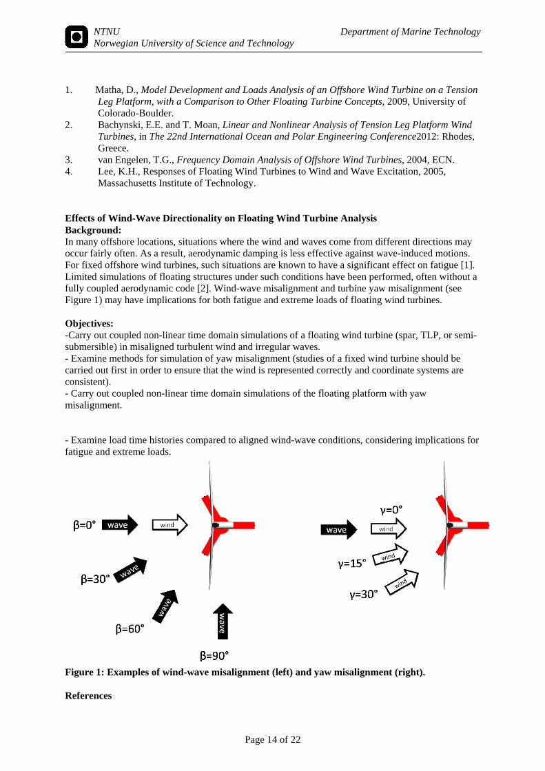
Massachusetts Institute of Technology. Effects of Wind-Wave Directionality on Floating Wind Turbine Analysis Background: In many offshore locations, situations where the wind and waves come from different directions may occur fairly often. As a result, aerodynamic damping is less effective against wave-induced motions. For fixed offshore wind turbines, such situations are known to have a significant effect on fatigue [1]. Limited simulations of floating structures under such conditions have been performed, often without a fully coupled aerodynamic code [2]. Wind-wave misalignment and turbine yaw misalignment (see Figure 1) may have implications for both fatigue and extreme loads of floating wind turbines. Objectives: -Carry out coupled non-linear time domain simulations of a floating wind turbine (spar, TLP, or semi-submersible) in misaligned turbulent wind and irregular waves. - Examine methods for simulation of yaw misalignment (studies of a fixed wind turbine should be carried out first in order to ensure that the wind is represented correctly and coordinate systems are consistent). - Carry out coupled non-linear time domain simulations of the floating platform with yaw misalignment. - Examine load time histories compared to aligned wind-wave conditions, considering implications for fatigue and extreme loads.
Figure 1: Examples of wind-wave misalignment (left) and yaw misalignment (right). References
NTNU Department of Marine Technology Norwegian University of Science and Technology
Page 15 of 22
1. Schløer, S., H.B., H. Bingham, and T. Larsen, Fully Nonlinear Wave Forcing on an Offshore Wind Turbine. Structural Response and Fatigue. Energy Procedia (under review), 2013.
2. Lygren, J.E.L., Dynamic Response Analysis of a Tension-Leg Wind Turbine, 2012, Norwegian University of Science and Technology.
Steep Wave Loads on Tension Leg Platform Wind Turbines Background: Tension leg platform wind turbines (TLPWTs) have heave, pitch, and roll natural frequencies which fall above the wave frequency. These modes may be excited by nonlinear wave loads, leading to large responses in large, steep waves. Several models for the wave excitation force and moment have been considered for similar structures (Morison’s Equation [1], FNV [2-4], Rainey [5]). There is disagreement about the necessity of considering the nonlinear wave surface and the influence of viscous forces [6]. For wind turbines, there are additional unknowns regarding the effects of the operational rotor. Objectives: - Implement and compare wave loads due to the different force models for steep waves. - Estimate the extreme tendon loads according to different models. - The effects of viscous damping, structural damping, and control system modifications on the responses can also be investigated. The Simo-Riflex (+AeroDyn) software can be used for this purpose, although certain ringing models will require writing external force models. References 1. Faltinsen, O.M., Sea Loads on Ships and Offshore Structures. 1990. 2. Faltinsen, O.M., J.N. Newman, and T. Vinje, Nonlinear wave loads on a slender vertical
cylinder. Journal of Fluid Mechanics, 1995. 289: p. 179-198. 3. Newman, J.N., Waves and nonlinear processes in hydrodynamics, 1996, Kluwer. p. 91-102. 4. Johannessen, T.B., Nonlinear Superposition Methods Applied to Continuous Ocean Wave
Spectra. Journal of Offshore Mechanics and Arctic Engineering, 2012. 134: p. 011302-1-011302-14.
5. Rainey, R.C.T., Slender-Body Expressions for the Wave Load on Offshore Structures. Proceedings: Mathematical and Physical Sciences, 1995. 450: p. 391-416.
Dynamic response analysis of TLP wind turbines with a simplified aerodynamic model Background: Due to a strong coupling between the wind- and wave-induced responses, coupled analysis tool is needed for dynamic response analysis of a floating wind turbine. Such analysis tools, e.g. FAST, HAWC2 and Simo/Riflex/Aerodyn, have been developed and the ongoing IEA OC4 project is to validate these tools by code-to-code comparison. Typically, in such tools, the aerodynamic loads are based on the BEM method, while the hydrodynamic loads are dealt with using either potential theory or the Morison’s formula. In view of a large number of wind and wave conditions to be considered for design of floating wind turbines, such analysis tools are still very time-consuming. A simplified method (Simo/Riflex/TDHMILL) has been developed, in which the aerodynamic loads are represented only by the thrust force acting on the whole rotor, as function of the relative velocity seen by the rotor taking into account the wind speed of the inflow and the motions of the floater. This simplified method has been validated through a comparison with HAWC2 for spar wind turbine [1]. Objective: The purpose of this work is to examine the validity of this simplified method for TLP wind turbines for which the tower responses due to flexible eigenmodes also matter, in addition to the rigid-body motions of the floater. A TLP wind turbine model with the NREL 5MW wind turbine will be built
NTNU Department of Marine Technology Norwegian University of Science and Technology
Page 16 of 22
using the software Simo/Riflex. Comparison of the dynamic responses due to both wind and wave loads in both operational and parked conditions using the Simo/Riflex/Aerodyn tool and the simplified method (Simo/Riflex/TDHMILL) will be conducted. To reduce the uncertainties in the comparison, exact wind and wave inputs will be considered for such comparison. Conclusions and recommendations on the use of this simplified method will be drawn upon the findings from this study. Reference 1. Karimirad, M. and Moan, T., ‘A Simplified Method for Coupled Analysis of Floating Offshore Wind
Turbines’, on-line, J. Marine Structures, 2012. Frequency-domain method for dynamic response analysis of floating wind turbines for fatigue design Background: Although time-domain coupled response analysis is preferred for design of floating wind turbines, the computational efforts involved in the numerical simulations are significant, especially various load conditions (operational, parked and fault conditions) need to be considered as specified by the design code e.g. IEC 61400-3. Time-domain method has the advantage to possibly include all of the nonlinearity in aerodynamic and hydrodynamic loads, in mooring system and due to large floater motions. However, it might be suffice to use linearized models for fatigue analysis when the moderate environmental conditions dominate in the fatigue assessment and the nonlinearity in such conditions might not be so significant. Frequency-domain methods for linear and second-order wave loads and responses have been developed and used for fatigue analysis of offshore oil and gas platforms. Such methods can still be used for wave-induced fatigue analysis of floating wind turbines. The aerodynamic loads on the wind turbine rotor are in principle nonlinear. However, for a given mean wind speed, such loads might be estimated using a linearized model and then the frequency-domain method can be used to obtain the structural response under such loads and to estimate the fatigue damage. Objective: The objective of this thesis is to develop a linearized model of a semi-submersible type floating wind turbine and applied to illustrate the feasibility of the developed frequency-domain method, with focus on the fatigue analysis for the brace-column joints. Comparison between the fatigue damages obtained by the frequency-domain method and the time-domain simulations will be made to show the validity of the frequency-domain method. Integrated long-term analysis of floating turbines to estimate extreme response or fatigue damage, considering fault conditions Project description Wind turbine systems are subjected to faults which refer to the unpermitted deviation of characteristic properties from the acceptable conditions. Some severe faults such as the pitch actuator faults require immediate detection and accommodation as they pose threat to the safety of turbines. Some situations involving blade pitch-to-feather shut down have been studied in [1, 2]. In comparison, other benign fault conditions may not be detected at an early stage. Sensor faults [3] are among them. Take the pitch sensor fault. A biased pitch sensor measurement affects both the closed-loop pitch system and the pitch angle measurement [4]. The dynamic responses of floating wind turbines under fault conditions are different, and the differences may vary at various sea states and turbulent wind. Since

NTNU Department of Marine Technology Norwegian University of Science and Technology
Page 17 of 22
the fatigue life of turbine components is sensitive to the control strategies [5], it is expected that the sensor faults, e.g. pitch sensor and yaw sensor, will affect the long-term fatigue life. Objective The effects of pitch sensor and yaw sensor faults on different components of the floating wind turbines are evaluated. Components, such as blades, tower, shaft, and mooring lines should be studied. If possible, the fatigue limit state functions can be established to evaluate the reliability of components. Numerical tools HAWC2/ Simo-Riflex-AeroDyn for the integrated analysis of a particular floating wind turbine WAFO toolbox for carrying out rain flow counting of fatigue damage PROBAN for reliability analysis References [1] Jiang, Z., Karimirad, M., Moan, T., Dynamic response analysis of wind turbines under blade pitch system fault, grid loss and shut down events, Under review in Wind Energy 2012. [2] Bachynski, E.E., Etemaddar, M., Kvittem, M.I., Luan, C., Moan, T., Dynamic analysis of floating wind turbines during pitch actuator fault, grid loss, and shutdown, DeepWind 2013, 10th Deep Sea Offshore Wind R&D Conference, Trondheim, Norway, 2013. [3] Odgaard, P.F., Johnson, K.E., Wind turbine fault detection and fault tolerant control-a second challenge, 2012 [4] Esbensen, T., Sloth, C., Fault Diagnosis and Fault-Tolerant Control of Wind Turbines, Master Thesis, Aalborg University, Department of Electronic Systems, 2009 [5] Skaare, B., Hanson, T.D., Nielsen, F.G., Importance of control strategies on fatigue life of floating wind turbines, ASME, 2007. Design wave load effects for floating platforms The work may involve the following tasks: 1. Literature study of the background of relevant computer program for calculating hydrodynamic
loads on a semi submersible or novel ship types (e.g. large container vessels, cruise vessels) 2. Carry out systematic long-term response analyses of section forces in a given platform or ship hull
as a reference for calibrating simplified approaches (see items 3 and 4). 3. Compare the use of a set of design sea-states according to a so-called contour lines (a novel
method to be specified in the new Norwegian Offshore standard to be introduced in 1999 to replace the NPD standard)
4. Calibrate a design wave method for the given platform based on results in item 2). Compare the wave height and – length relations obtained e.g. with current DNV guidelines for floaters.
Aerodynamics of floating wind turbines operating in wake effect
NTNU Department of Marine Technology Norwegian University of Science and Technology
Page 18 of 22
Background: Studying the wake behind a wind turbine rotor is of interest not only in determining loads on the rotor, but also because it prescribes the inflow to any subsequent downstream rotors - for a general overview, see e.g. [1, 2]. In order to investigate the performance and wake development for two model wind turbine, the Department of Energy and Process Engineering at NTNU recently undertook extended wind tunnel tests on two rotors operating in tandem. As part of a so-called “blind test”, participant were invited to simulate the experiment using numerical tools, and to compare results to measurements [3]. To investigate the validity of engineering type aerodynamic models used in the integrated analysis tools for floating wind turbines, an axis-symmetric moving actuator disc model (axMAD) was implemented in FLUENT (see [4]). By adding a downwind turbine, and restricting the back-and-forth surge motion of both turbines, this model was used to simulate the above mentioned blind test wind tunnel experiment. As follow up to the original, results from the blind test can now be used to improve the computational model. The surge motion degree of freedom (representing motion of a TLP type floating platform) can also be reactivated, so that the turbines are free to displace axially based on experienced aerodynamic loads, which will be of interest especially for the downwind turbine operating in the wake of the upstream one. Objectives: The objectives for this project can thus be summarized as the selection of an appropriate turbulence model and generation of an optimal mesh so that results from the wind tunnel experiments are replicated as close as possible. This is to be followed up by an investigation of the effects on the flow field and rotor loads, in case rotors are free to move in surge (like floating wind turbines) in comparison to a the with fixed rotors, to establish the possible significance of platform motion. Numerical tools: FLUENT for numerical solution of the fluid dynamic problem, C for implementation of the MAD model, MatLab for post-processing of results. References: [1] L.J. Vermeer, J.N. Sørensen, and A. Crespo. “Wind turbine wake aerodynamics.” Progress in Aerospace Sciences, 39:467–510, 2003. [2] B. Sanderse, “Aerodynamics of wind turbine wakes.” Energy Research Center of the Netherlands, ECN-E–09-016, Petten, The Netherlands, 2009. [3] L. Sætra, “Wind and Wake Modelling – Blind Test 2.” DeepWind 2013 - 10th Deep Sea Offshore R&D Seminar, Trondheim, Norway, 2013. [4] J.B. de Vaal, M.O.L. Hansen, and T. Moan. “Effect of wind turbine surge motion on rotor thrust and induced velocity.” Wind Energy (online), 2012. Modelling and analysis of wave energy conversion plants Background:

NTNU Department of Marine Technology Norwegian University of Science and Technology
Page 19 of 22
Ocean waves represent a renewable source of energy and significant efforts are currently devoted to exploitation of wave energy by various concepts. A crucial issue is to balance the energy capture and the life cycle costs of the system. In particular, the exploitation of energy implies significant dynamic loading on the system. Moreover, the dynamic system involves structural, hydraulic, mechanical and electrical components. This pre-project thesis is concerned with modelling and analysis of a wave energy conversion device which consists of multiple body floating system. However, the pre-project thesis should focus on a two-body system. The general purpose of the dynamic analysis is in principle two-fold: to determine the energy absorption and to determine the loads for structural design. The following items should be addressed in this project: 1) Literature study on the hydrodynamic modelling of the two bodies, with a focus on load models for global motion and structural response. The model should include a simple model of the power off-take system. 2) Establish a linear dynamic model and carry out a sensitivity study, considering the effect of the control system in a simplified manner. 3) Refine the model by considering nonlinear hydrodynamic load effects. 4) As far as time allows, refine the dynamic model relating to the power off-take system. 5) Conclude and recommend future work.
Fatigue analysis of mobile semi-submersible platform or floating wind turbines The work may be carried out in the following steps: 1. Literature study of fatigue analysis of semi-submersibles, including hydrodynamic analysis, structural modelling and fatigue resistance. Relevant procedures outlined in guidelines and standards NORSOK and DNV) should be consulted. 2. Carry out fatigue analysis of a braced semi-submersible based on available load, load effect and resistance models.
NTNU Department of Marine Technology Norwegian University of Science and Technology
Page 20 of 22
3. Assess the structural model and investigate the sensitivity to alternative modelling, depending upon the likely influence of the modified model. This could include model of the deck (for global stiffness), column-brace connections (for local analysis) etc. 4. Investigate simplified methods to combine multiple response variables by comparison with accurate methods in which the phase lag etc. are properly accounted for. 5. Investigate simplified model of hydrodynamic loading based upon Morison-type loading as compared to source- sink approach based upon potential theory together with use of drag force to model viscous effects. 6. Investigate the accuracy of a simplified approach for estimating fatigue loading in terms of a long term Weibull distribution of stress ranges. The 20 yr. maximum is determined by a design wave approach calibrated by a stochastic approach. The shape factor is based on experience. The reference is based on a full stochastic analysis. 7. Analysis of the robustness to fatigue failure of individual braces as a basis for assessing the relevant fatigue design factor for use. 8. Conclude and recommend future work Mooring system analysis for platforms and wind turbines Background Mooring of platforms and wind turbines, especially in shallow water, is a significant challenge. The purpose of this work is to suggest and analyse a mooring system for floating wind turbines in water depths of 70m and 100 m. Assignment The work consists in
- Assessing the environmental loads (waves, current, wind), ice loads - Choosing mooring configuration (catenary chain, taut synthetic ropes, possible use of DP assistance for different types of floating systems - Use aadvanced simulation tools, like the SIMO-Riflex software to determine the wave- and
wind-induced response in the system - Design the mooring system - Investigate whether simplified mooring analysis methods are able to reproduce the results
obtained by the refined methods Finite element analysis of floating platforms or wind turbines The work may be carried out in the following steps. 1. Literature study of FE program SESAM, and modelling of floating platform or ship structure, to capture the true physical behaviour and limit the discretization error implied by a finite element model
NTNU Department of Marine Technology Norwegian University of Science and Technology
Page 21 of 22
2. Carry out finite element analysis of an idealised problem, to investigate the accuracy of the finite element mode1 and the behaviour of e.g. column-pontoon connection or another important substructure of the platform, or ship, based on shell elements. The effect of mesh refinement needs to be investigated in this connection. 3. Discuss results and carry out parametric study with a beam model to identify how the beam model (by using e.g. appropriate effective flange, flexible joint model) to fit the accurate solution (by shell element) with this model. 4. Compare results, conclude and propose further work (This work can be extended to cover global behaviour of a floating platform or ship, either by focusing on hydrodynamic loads and using a fairly simple global structural model or by focusing on the structural modelling for given load conditions.) Numerical simulation for installation of offshore monopile or jacket type wind turbines Background Transport and installation are important issues in connection with the life cycle costs of offshore wind farms. Fast and safe installation of offshore wind turbine components, including jacket foundation, transition piece, tower and rotor, is important for offshore wind farm economics. Very limited studies of installation operations have been conducted. The scope of the work is to study installation of mono-pile or a jacket wind turbines in the North Sea (e.g. the Sheringham Shoal wind farm) using a numerical simulation tool. The objective is to study the dynamic behaviour of the floating vessel during the installation and to evaluate the limiting wind and wave conditions for such installation. In particular, the crane operation for lowering a monopile or jacket structure through the wave zone down to the sea bed will be studied using numerical models. A coupled model, consisting of the floating installation vessel, the jacket structure and the connection between them with lift wires, will be built and analyzed using the Marintek software Simo. The focus will be given on the modelling of hydrodynamic forces on the jacket slender members (legs and braces) in the wave zone and on the analysis of the motion and structural responses in the system during the crane operation. Assignment The following tasks should be addressed: 1. Literature review on the general methods for offshore wind farm installation. This will include the installation procedure and plans, the types of installation vessels, the criteria used to carry out a safe installation operation, and the different wind turbine substructures (monopile, tripod, GBS and jacket). Study the long-term wind and wave data for the Sheringham Shoal site. 2. Numerical modeling of installation vessel. Hydrodynamic analysis using WAMIT with the panel model and the mass model for the vessel needs to be carried out. Look at the motion RAOs. Directionality of incident waves on the hydrodynamic property should also be checked. 3. Estimate the wave field at the monopile or jacket being lowering into the sea adjacent to the installation vessel, by accounting for diffraction effects, and estomate the wave forces on the object being installed.
NTNU Department of Marine Technology Norwegian University of Science and Technology
Page 22 of 22
4. Estimate the weather window based on simplified criteria for acceptable motions in different stages of the installation procedure. It is also interesting to look at the weather window for continuous installation of multiple turbines, not only one turbine. 5. Time-domain simulation of crane operation by using the software Simo. Various wind and wave conditions need to be considered in order to identify the limiting conditions for such operation. Different wind turbine size (3MW and 5MW) might be considered, which implied different weight of mono-pile and transition piece. 6. Establish the criteria for the installation vessel and analysis of the time series results to study under which wind and wave conditions the criteria are satisfied. 7. If time allows, study the effect of the DP system of the installation vessel on the vessel motions. 8.Conclusions and recommendation about future work April 03.2013 T.Moan