Embed Size (px)
Citation preview

1
MnROADS NGCS LITE Test Strip Evaluation On July 10, 2010 Husqvarna Construction Products and Interstsate Improvement, Inc. constructed a test strip on Cell 37 of the MnROADs Low Volume Road test facility to demonstrate the ability of one of their specialty blades to provide additional texture on the land of the NGCS surface; a process termed NGCS LITE. Testing conducted on July 11 indicated the overall OBSI level was 99.8 dBA. .
Photo of NGCS LITE Texture
2011
ACPA Larry Scofield
1/11/2011
2
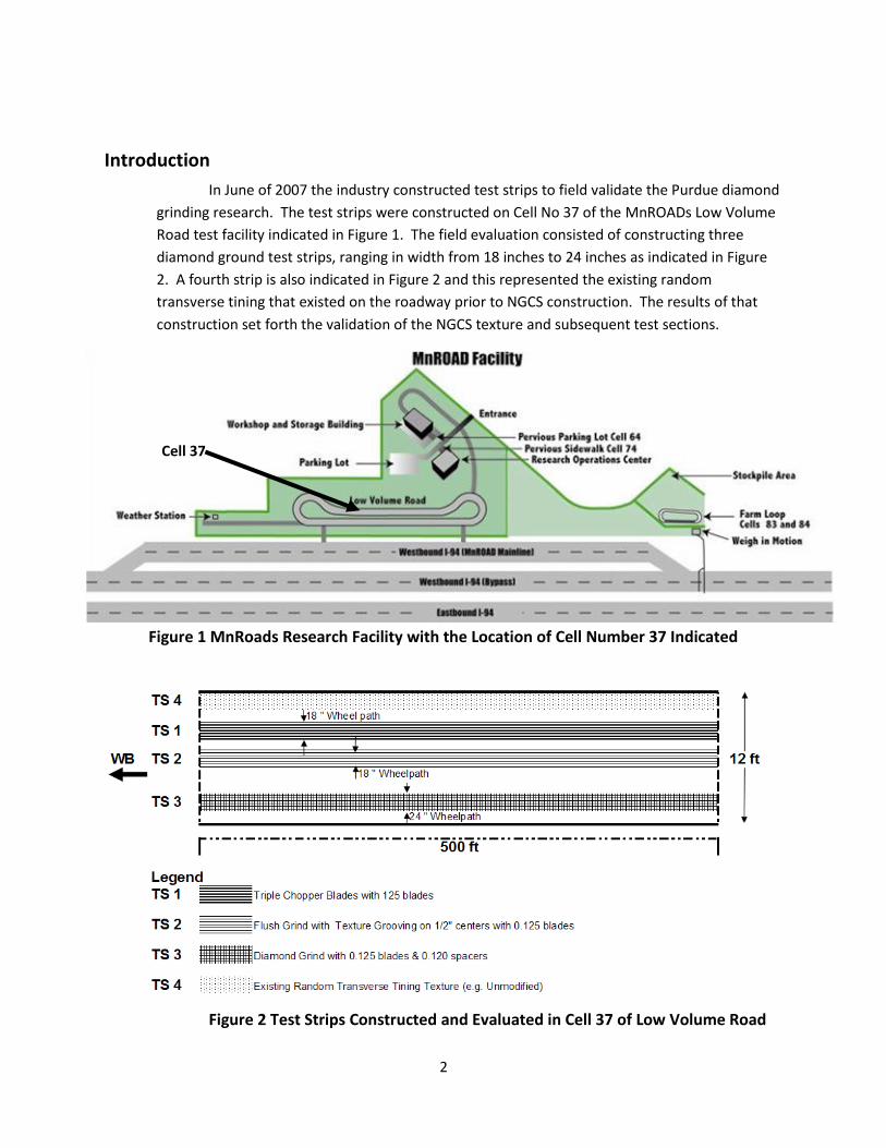
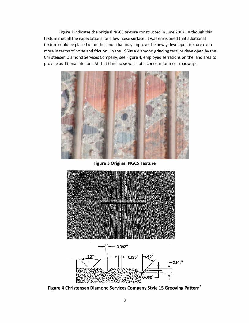
Introduction
In June of 2007 the industry constructed test strips to field validate the Purdue diamond
grinding research. The test strips were constructed on Cell No 37 of the MnROADs Low Volume
Road test facility indicated in Figure 1. The field evaluation consisted of constructing three
diamond ground test strips, ranging in width from 18 inches to 24 inches as indicated in Figure
2. A fourth strip is also indicated in Figure 2 and this represented the existing random
transverse tining that existed on the roadway prior to NGCS construction. The results of that
construction set forth the validation of the NGCS texture and subsequent test sections.
Figure 1 MnRoads Research Facility with the Location of Cell Number 37 Indicated
Figure 2 Test Strips Constructed and Evaluated in Cell 37 of Low Volume Road
Cell 37
3
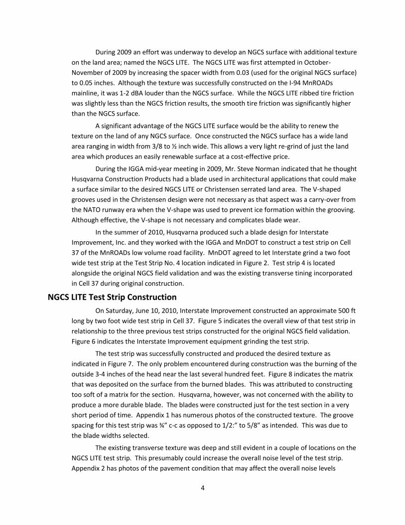
Figure 3 indicates the original NGCS texture constructed in June 2007. Although this
texture met all the expectations for a low noise surface, it was envisioned that additional
texture could be placed upon the lands that may improve the newly developed texture even
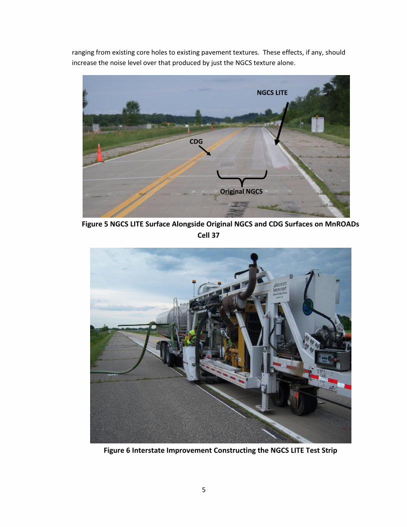
more in terms of noise and friction. In the 1960s a diamond grinding texture developed by the
Christensen Diamond Services Company, see Figure 4, employed serrations on the land area to
provide additional friction. At that time noise was not a concern for most roadways.
Figure 3 Original NGCS Texture
Figure 4 Christensen Diamond Services Company Style 15 Grooving Pattern1
4
During 2009 an effort was underway to develop an NGCS surface with additional texture
on the land area; named the NGCS LITE. The NGCS LITE was first attempted in October-
November of 2009 by increasing the spacer width from 0.03 (used for the original NGCS surface)
to 0.05 inches. Although the texture was successfully constructed on the I-94 MnROADs
mainline, it was 1-2 dBA louder than the NGCS surface. While the NGCS LITE ribbed tire friction
was slightly less than the NGCS friction results, the smooth tire friction was significantly higher
than the NGCS surface.
A significant advantage of the NGCS LITE surface would be the ability to renew the
texture on the land of any NGCS surface. Once constructed the NGCS surface has a wide land
area ranging in width from 3/8 to ½ inch wide. This allows a very light re-grind of just the land
area which produces an easily renewable surface at a cost-effective price.
During the IGGA mid-year meeting in 2009, Mr. Steve Norman indicated that he thought
Husqvarna Construction Products had a blade used in architectural applications that could make
a surface similar to the desired NGCS LITE or Christensen serrated land area. The V-shaped
grooves used in the Christensen design were not necessary as that aspect was a carry-over from
the NATO runway era when the V-shape was used to prevent ice formation within the grooving.
Although effective, the V-shape is not necessary and complicates blade wear.
In the summer of 2010, Husqvarna produced such a blade design for Interstate
Improvement, Inc. and they worked with the IGGA and MnDOT to construct a test strip on Cell
37 of the MnROADs low volume road facility. MnDOT agreed to let Interstate grind a two foot
wide test strip at the Test Strip No. 4 location indicated in Figure 2. Test strip 4 is located
alongside the original NGCS field validation and was the existing transverse tining incorporated
in Cell 37 during original construction.
NGCS LITE Test Strip Construction
On Saturday, June 10, 2010, Interstate Improvement constructed an approximate 500 ft
long by two foot wide test strip in Cell 37. Figure 5 indicates the overall view of that test strip in
relationship to the three previous test strips constructed for the original NGCS field validation.
Figure 6 indicates the Interstate Improvement equipment grinding the test strip.
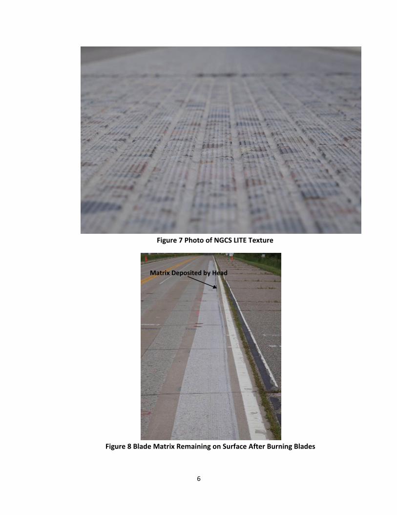
The test strip was successfully constructed and produced the desired texture as
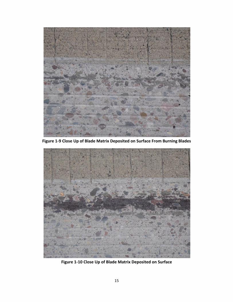
indicated in Figure 7. The only problem encountered during construction was the burning of the
outside 3-4 inches of the head near the last several hundred feet. Figure 8 indicates the matrix
that was deposited on the surface from the burned blades. This was attributed to constructing
too soft of a matrix for the section. Husqvarna, however, was not concerned with the ability to
produce a more durable blade. The blades were constructed just for the test section in a very
short period of time. Appendix 1 has numerous photos of the constructed texture. The groove
spacing for this test strip was ¾” c-c as opposed to 1/2:” to 5/8” as intended. This was due to
the blade widths selected.
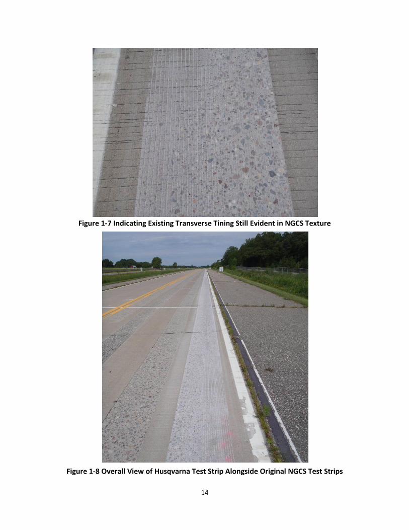
The existing transverse texture was deep and still evident in a couple of locations on the
NGCS LITE test strip. This presumably could increase the overall noise level of the test strip.
Appendix 2 has photos of the pavement condition that may affect the overall noise levels
5
ranging from existing core holes to existing pavement textures. These effects, if any, should
increase the noise level over that produced by just the NGCS texture alone.
Figure 5 NGCS LITE Surface Alongside Original NGCS and CDG Surfaces on MnROADs
Cell 37
Figure 6 Interstate Improvement Constructing the NGCS LITE Test Strip
NGCS LITE
Original NGCS
CDG
6
Figure 7 Photo of NGCS LITE Texture
Figure 8 Blade Matrix Remaining on Surface After Burning Blades
Matrix Deposited by Head
7
The groove depths ranged between 2/32 and 3/32 of an inch, with most of the section
at 2/32 inch. The spacing of the grooves was approaching ¾ of an inch although it was suppose
to be at 5/8 of an inch.
OBSI Testing of NGCS LITE Test Strip
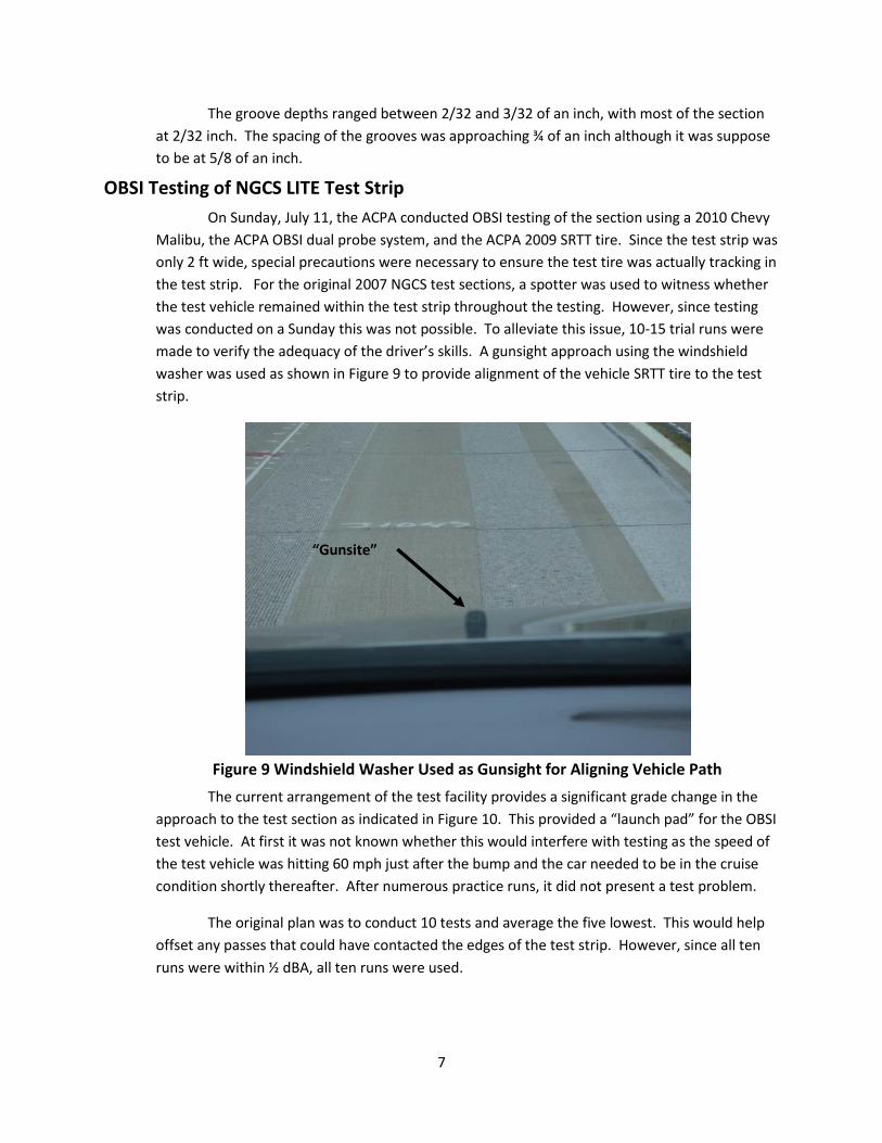
On Sunday, July 11, the ACPA conducted OBSI testing of the section using a 2010 Chevy
Malibu, the ACPA OBSI dual probe system, and the ACPA 2009 SRTT tire. Since the test strip was
only 2 ft wide, special precautions were necessary to ensure the test tire was actually tracking in
the test strip. For the original 2007 NGCS test sections, a spotter was used to witness whether
the test vehicle remained within the test strip throughout the testing. However, since testing
was conducted on a Sunday this was not possible. To alleviate this issue, 10-15 trial runs were
made to verify the adequacy of the driver’s skills. A gunsight approach using the windshield
washer was used as shown in Figure 9 to provide alignment of the vehicle SRTT tire to the test
strip.
Figure 9 Windshield Washer Used as Gunsight for Aligning Vehicle Path
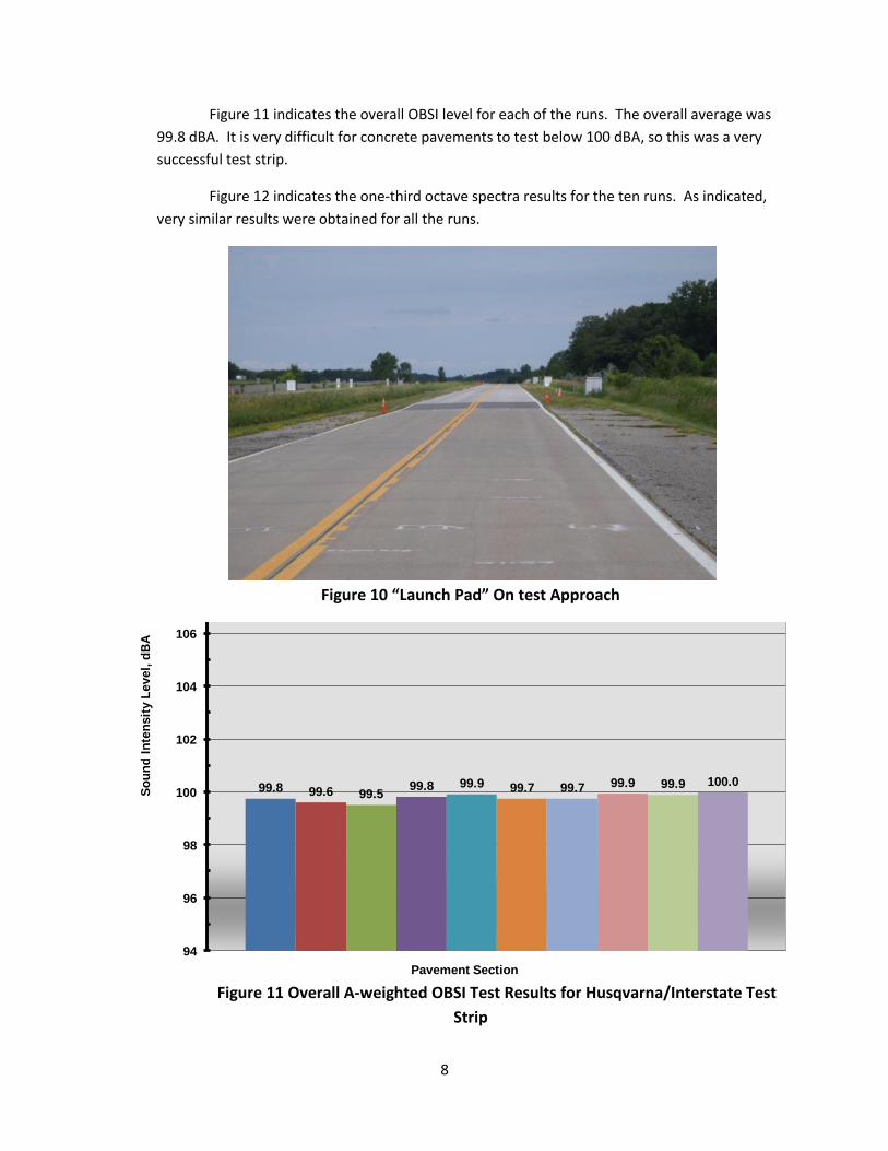
The current arrangement of the test facility provides a significant grade change in the
approach to the test section as indicated in Figure 10. This provided a “launch pad” for the OBSI
test vehicle. At first it was not known whether this would interfere with testing as the speed of
the test vehicle was hitting 60 mph just after the bump and the car needed to be in the cruise
condition shortly thereafter. After numerous practice runs, it did not present a test problem.
The original plan was to conduct 10 tests and average the five lowest. This would help
offset any passes that could have contacted the edges of the test strip. However, since all ten
runs were within ½ dBA, all ten runs were used.
“Gunsite”
8
Figure 11 indicates the overall OBSI level for each of the runs. The overall average was
99.8 dBA. It is very difficult for concrete pavements to test below 100 dBA, so this was a very
successful test strip.
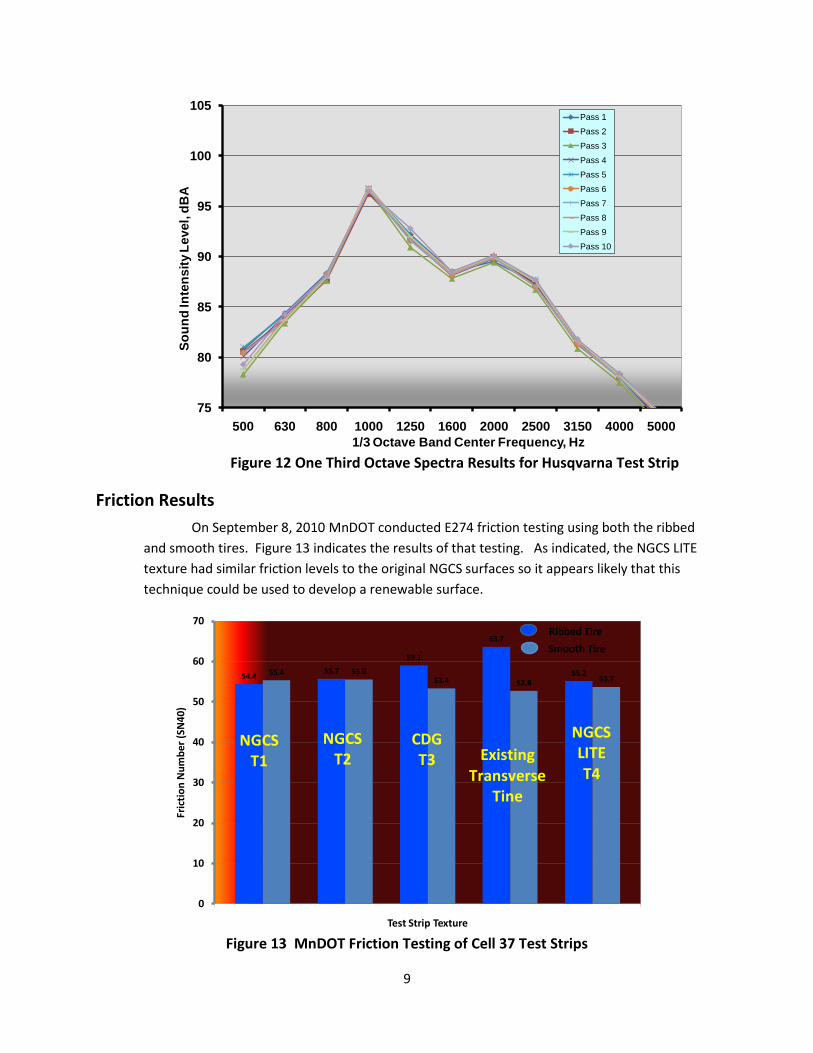
Figure 12 indicates the one-third octave spectra results for the ten runs. As indicated,
very similar results were obtained for all the runs.
Figure 10 “Launch Pad” On test Approach
Figure 11 Overall A-weighted OBSI Test Results for Husqvarna/Interstate Test
Strip
99.8 99.6 99.599.8 99.9 99.7 99.7 99.9 99.9 100.0
94
96
98
100
102
104
106
108
110
So
un
d I
nte
nsit
y L
evel,
dB
A
Pavement Section
XX & XX OBSIOverall A-wtd Levels
9
Figure 12 One Third Octave Spectra Results for Husqvarna Test Strip
Friction Results
On September 8, 2010 MnDOT conducted E274 friction testing using both the ribbed
and smooth tires. Figure 13 indicates the results of that testing. As indicated, the NGCS LITE
texture had similar friction levels to the original NGCS surfaces so it appears likely that this
technique could be used to develop a renewable surface.
Figure 13 MnDOT Friction Testing of Cell 37 Test Strips
75
80
85
90
95
100
105
500 630 800 1000 1250 1600 2000 2500 3150 4000 5000
So
un
d In
ten
sit
y L
evel,
dB
A
1/3 Octave Band Center Frequency, Hz
MnROADS Husqavarna NGCS Results
Pass 1
Pass 2
Pass 3
Pass 4
Pass 5
Pass 6
Pass 7
Pass 8
Pass 9
Pass 10
54.4 55.4 55.7 55.6
59.1
53.4
63.7
52.855.2
53.7
0
10
20
30
40
50
60
70
Fric
tio
n N
um
be
r (S
N4
0)
Test Strip Texture
Friction Results for MnROADS Cell 37 Test Strips 9/8/10
NGCST1
NGCST2
CDGT3 Existing
Transverse Tine
NGCSLITET4
Smooth Tire
Ribbed Tire
10
Summary
The test strip was successfully placed and resulted in the desired surface texture. The
OBSI results were below 100 dBA. Friction test results are similar to the original NGCS surface so
it appears likely that this texture can be used as a renewable surface.
The difference between the original NGCS and the NGCS LITE can be observed by
contrasting Figures 3 and 7.
Prior to full scale implementation of this texture, there needs to larger test sections of
this texture placed under traffic conditions. This will allow evaluation of the blades ability to
successfully operate in a production environment. It will also allow time series evaluation of the
texture under traffic for both noise and friction.
References
1. Sherman,G.B.;Skog,J.B.;and Johnson,M.H., “Effect of Pavement Grooving on Motorcycle Rideability”, California Department of Public Works-Highways Division, November 1969
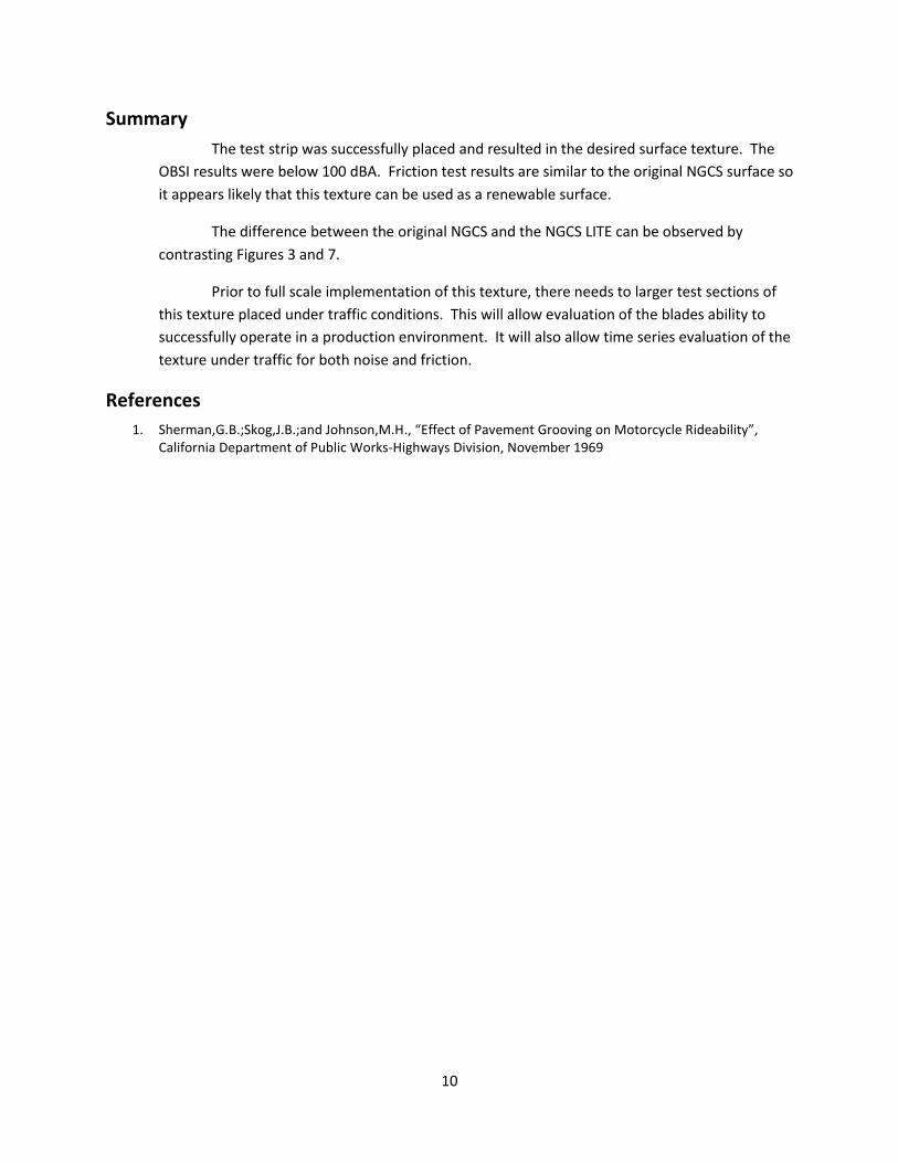
Appendix 1 Photos of Husqvarna/Interstate NGCS Texture
11
Figure 1-1 Close Up of Husqvarna NGCS Texture
Figure 1-2 Close Up of Husqvarna NGCS Texture w/Ruler
12
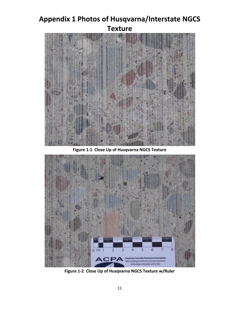
Figure 1-3 Angle View of Husqvarna NGCS Texture
Figure 1-4 Angle View of Husqvarna NGCS Texture
13
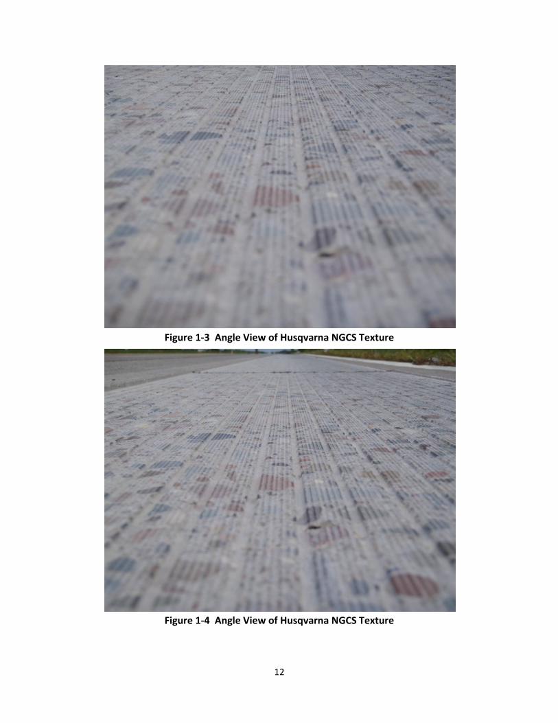
Figure 1-5 Angle View of Husqvarna NGCS Texture
Figure 1-6 Existing Transverse Texture within NGCS Test Strip
14
Figure 1-7 Indicating Existing Transverse Tining Still Evident in NGCS Texture
Figure 1-8 Overall View of Husqvarna Test Strip Alongside Original NGCS Test Strips
15
Figure 1-9 Close Up of Blade Matrix Deposited on Surface From Burning Blades
Figure 1-10 Close Up of Blade Matrix Deposited on Surface
16
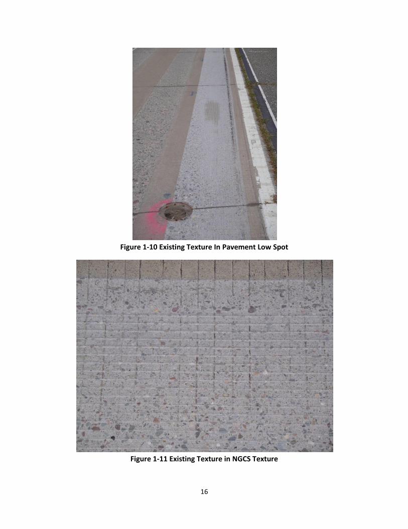
Figure 1-10 Existing Texture In Pavement Low Spot
Figure 1-11 Existing Texture in NGCS Texture
17
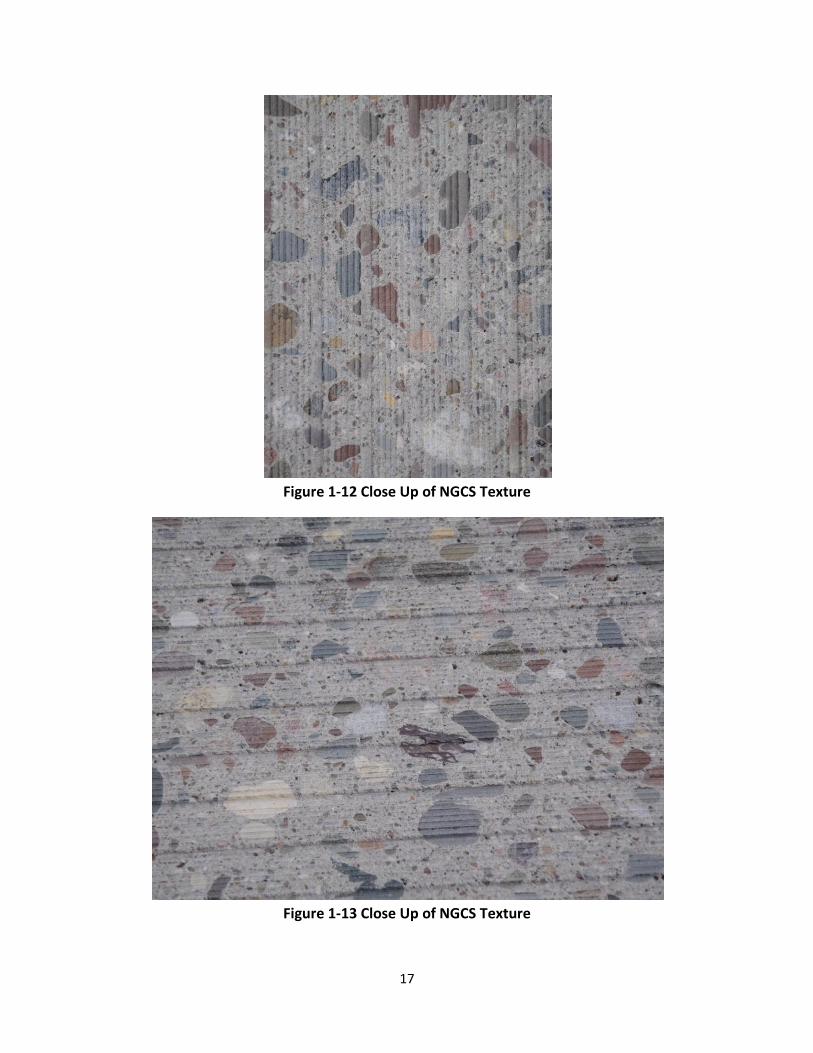
Figure 1-12 Close Up of NGCS Texture
Figure 1-13 Close Up of NGCS Texture
18
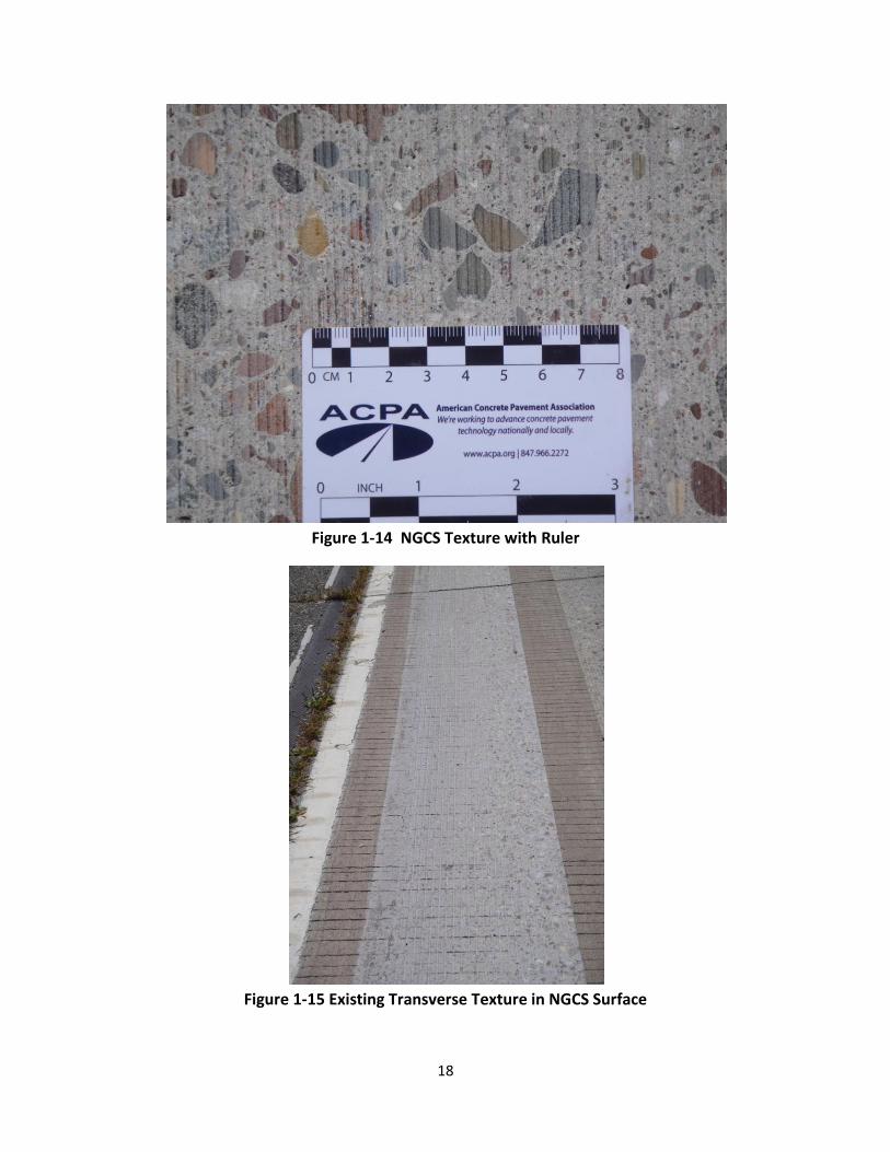
Figure 1-14 NGCS Texture with Ruler
Figure 1-15 Existing Transverse Texture in NGCS Surface
19
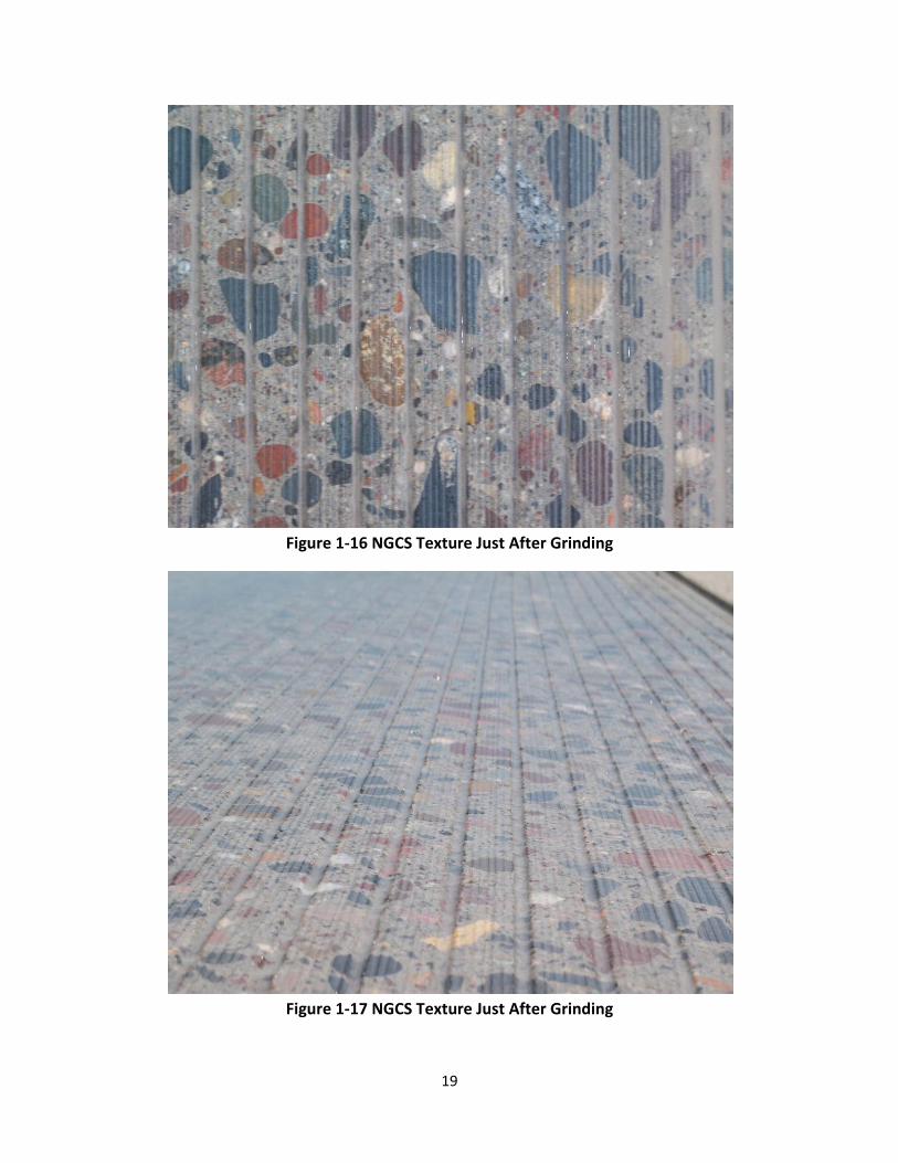
Figure 1-16 NGCS Texture Just After Grinding
Figure 1-17 NGCS Texture Just After Grinding
20
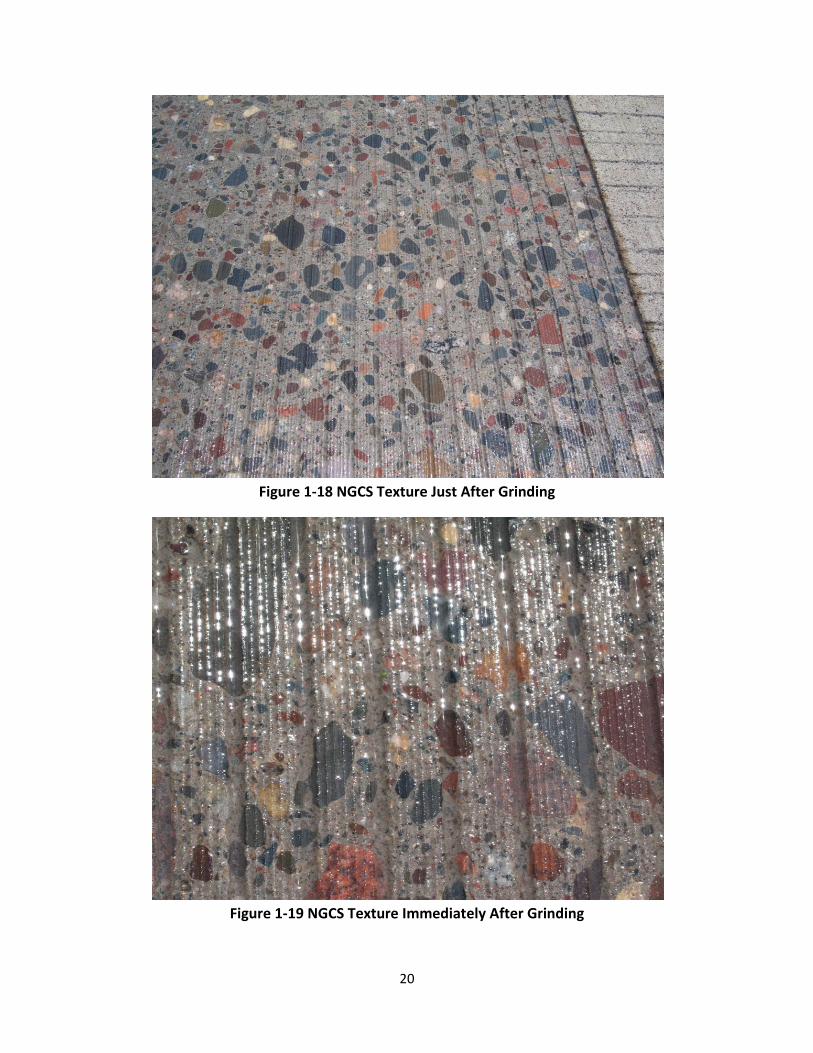
Figure 1-18 NGCS Texture Just After Grinding
Figure 1-19 NGCS Texture Immediately After Grinding
21
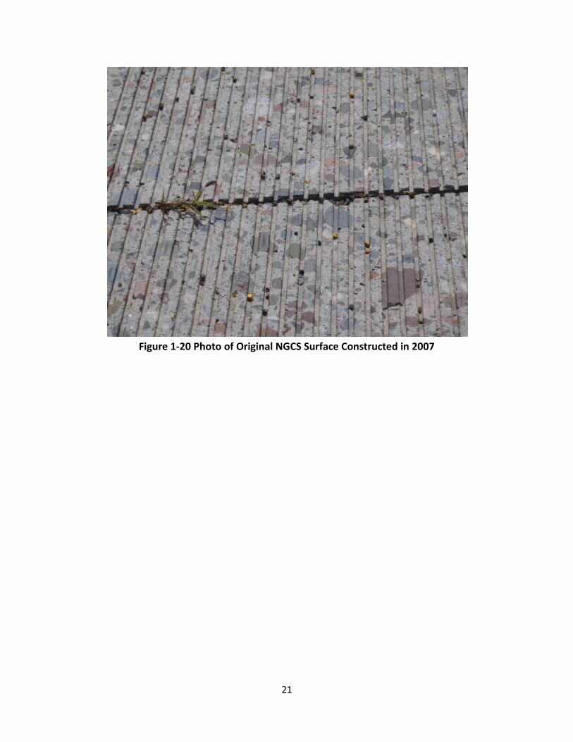
Figure 1-20 Photo of Original NGCS Surface Constructed in 2007
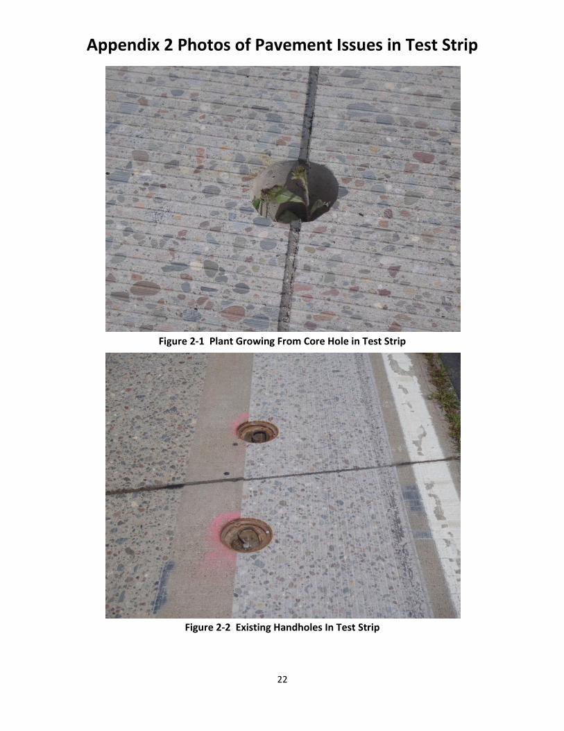
Appendix 2 Photos of Pavement Issues in Test Strip
22
Figure 2-1 Plant Growing From Core Hole in Test Strip
Figure 2-2 Existing Handholes In Test Strip
23
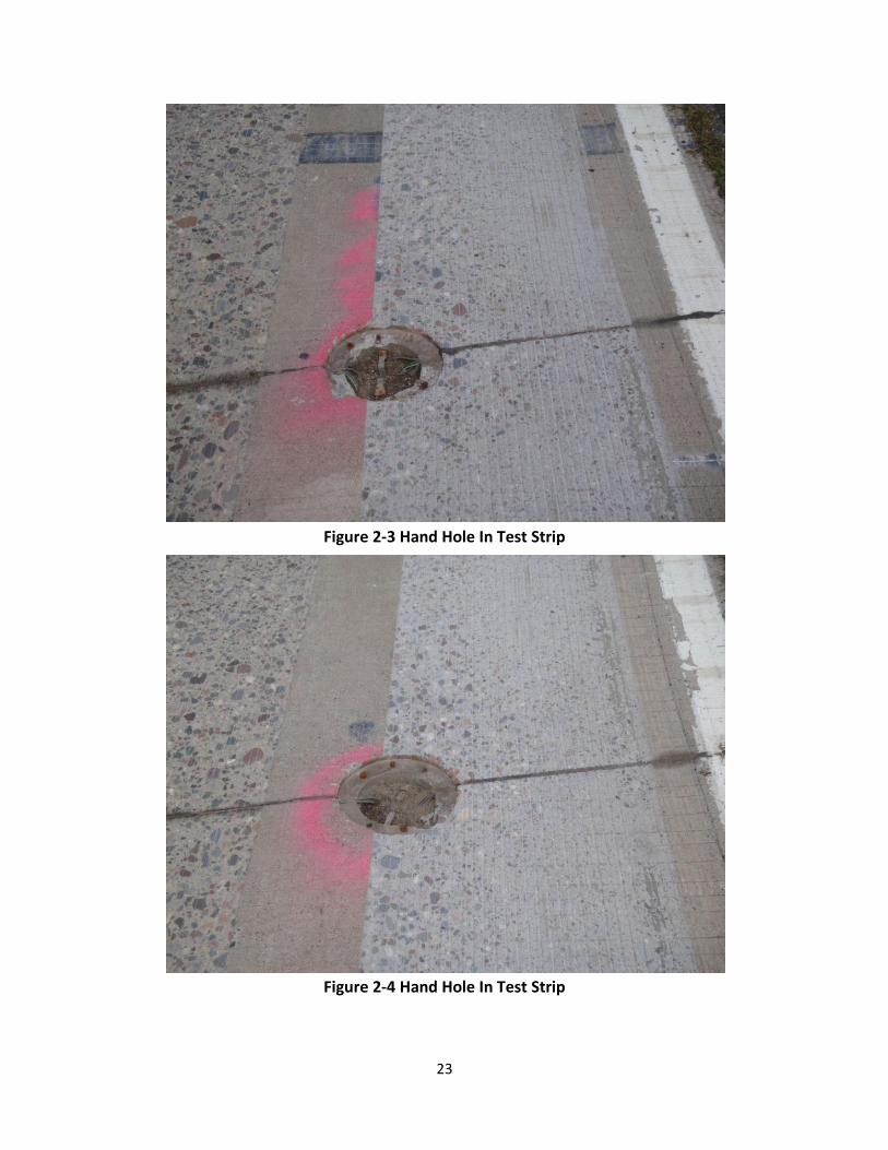
Figure 2-3 Hand Hole In Test Strip
Figure 2-4 Hand Hole In Test Strip
24
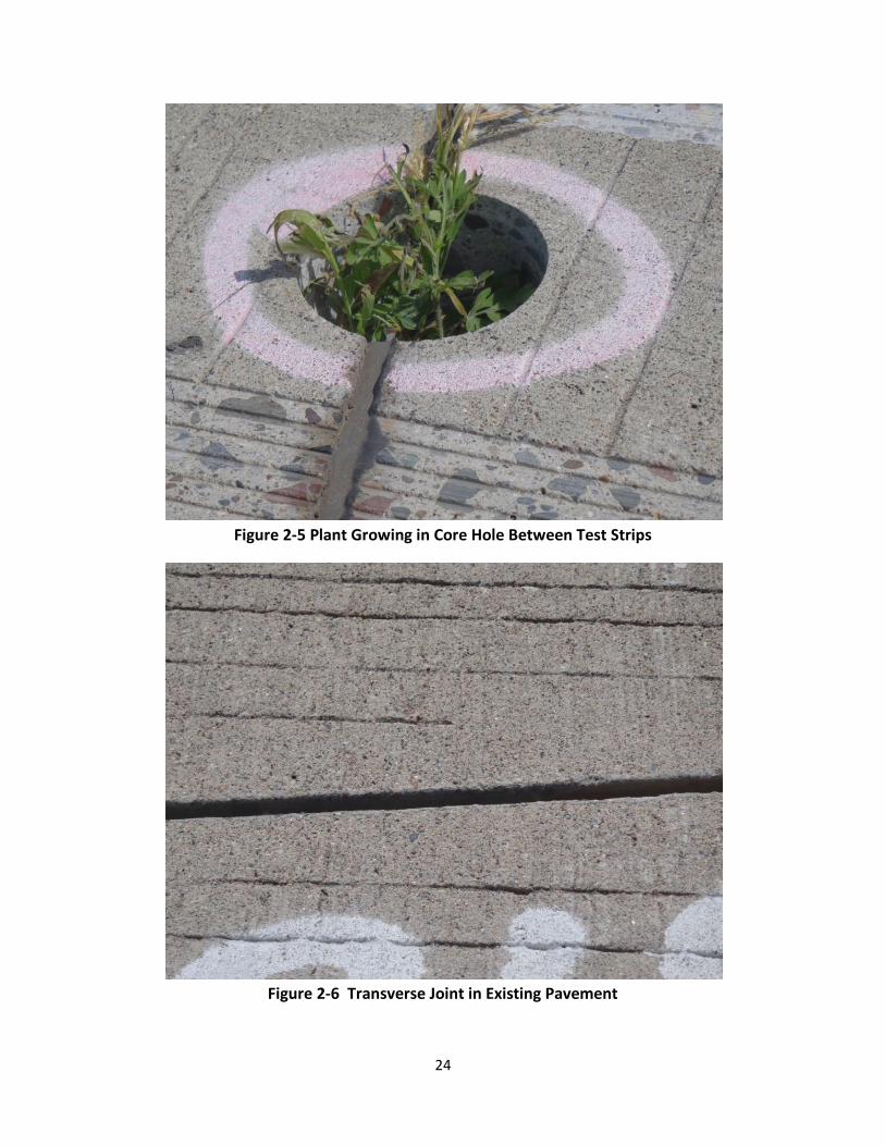
Figure 2-5 Plant Growing in Core Hole Between Test Strips
Figure 2-6 Transverse Joint in Existing Pavement