Embed Size (px)
Citation preview

GLC Generator
(Gaseous Liquid Cooled)
GLC30, 35, 45, 50, 60, 80, 100 and 125
Installation & Operating Manual
5/04 MN2408
WARNING:CALIFORNIA PROPOSITION 65 WARNING:
Engine exhaust from this product contains chemicals knownto the state of California to cause cancer, birth defects andother reproductive harm.
WARNING:CALIFORNIA PROPOSITION 65 WARNING:
Battery posts, terminals and related accessories are known tothe state of California to cause cancer, birth defects and otherreproductive harm.

Table of Contents
Table of Contents iMN2408
Section 1Product Safety Information 1-1. . . . . . . . . . . . . . . . . . . . . . . . . . . . . . . . . . . . . . . . . . . . . . . . . . . . . . . . . . . . . . . . . . . . . . . .
Safety Notice 1-1. . . . . . . . . . . . . . . . . . . . . . . . . . . . . . . . . . . . . . . . . . . . . . . . . . . . . . . . . . . . . . . . . . . . . . . . . . . . . . . . . Responsibility 1-1. . . . . . . . . . . . . . . . . . . . . . . . . . . . . . . . . . . . . . . . . . . . . . . . . . . . . . . . . . . . . . . . . . . . . . . . . . . . . . . . . IMPORTANT SAFETY INSTRUCTIONS 1-2. . . . . . . . . . . . . . . . . . . . . . . . . . . . . . . . . . . . . . . . . . . . . . . . . . . . . . . . . .
Section 2General Information 2-1. . . . . . . . . . . . . . . . . . . . . . . . . . . . . . . . . . . . . . . . . . . . . . . . . . . . . . . . . . . . . . . . . . . . . . . . . . . . . .
Limited Warranty 2-1. . . . . . . . . . . . . . . . . . . . . . . . . . . . . . . . . . . . . . . . . . . . . . . . . . . . . . . . . . . . . . . . . . . . . . . . . . . . . . Installation Guidelines 2-3. . . . . . . . . . . . . . . . . . . . . . . . . . . . . . . . . . . . . . . . . . . . . . . . . . . . . . . . . . . . . . . . . . . . . . . . . Site Planning 2-3. . . . . . . . . . . . . . . . . . . . . . . . . . . . . . . . . . . . . . . . . . . . . . . . . . . . . . . . . . . . . . . . . . . . . . . . . . . . . . . . .
Room Size 2-3. . . . . . . . . . . . . . . . . . . . . . . . . . . . . . . . . . . . . . . . . . . . . . . . . . . . . . . . . . . . . . . . . . . . . . . . . . . . . . . Room Location 2-4. . . . . . . . . . . . . . . . . . . . . . . . . . . . . . . . . . . . . . . . . . . . . . . . . . . . . . . . . . . . . . . . . . . . . . . . . . . Foundation Design 2-5. . . . . . . . . . . . . . . . . . . . . . . . . . . . . . . . . . . . . . . . . . . . . . . . . . . . . . . . . . . . . . . . . . . . . . . .
Exhaust System 2-9. . . . . . . . . . . . . . . . . . . . . . . . . . . . . . . . . . . . . . . . . . . . . . . . . . . . . . . . . . . . . . . . . . . . . . . . . . . . . . Level Of Attenuation 2-9. . . . . . . . . . . . . . . . . . . . . . . . . . . . . . . . . . . . . . . . . . . . . . . . . . . . . . . . . . . . . . . . . . . . . . . System Placement 2-9. . . . . . . . . . . . . . . . . . . . . . . . . . . . . . . . . . . . . . . . . . . . . . . . . . . . . . . . . . . . . . . . . . . . . . . . Multi�Engine Installations 2-9. . . . . . . . . . . . . . . . . . . . . . . . . . . . . . . . . . . . . . . . . . . . . . . . . . . . . . . . . . . . . . . . . . Exhaust Manifold 2-9. . . . . . . . . . . . . . . . . . . . . . . . . . . . . . . . . . . . . . . . . . . . . . . . . . . . . . . . . . . . . . . . . . . . . . . . . Exhaust Gas Restriction 2-9. . . . . . . . . . . . . . . . . . . . . . . . . . . . . . . . . . . . . . . . . . . . . . . . . . . . . . . . . . . . . . . . . . . Exhaust Piping 2-10. . . . . . . . . . . . . . . . . . . . . . . . . . . . . . . . . . . . . . . . . . . . . . . . . . . . . . . . . . . . . . . . . . . . . . . . . . . Rain Protection 2-10. . . . . . . . . . . . . . . . . . . . . . . . . . . . . . . . . . . . . . . . . . . . . . . . . . . . . . . . . . . . . . . . . . . . . . . . . . .
Cooling System 2-11. . . . . . . . . . . . . . . . . . . . . . . . . . . . . . . . . . . . . . . . . . . . . . . . . . . . . . . . . . . . . . . . . . . . . . . . . . . . . . . Air System 2-17. . . . . . . . . . . . . . . . . . . . . . . . . . . . . . . . . . . . . . . . . . . . . . . . . . . . . . . . . . . . . . . . . . . . . . . . . . . . . . . . . . .
Radiator Cooling 2-17. . . . . . . . . . . . . . . . . . . . . . . . . . . . . . . . . . . . . . . . . . . . . . . . . . . . . . . . . . . . . . . . . . . . . . . . . . Other Engine Cooling Systems 2-18. . . . . . . . . . . . . . . . . . . . . . . . . . . . . . . . . . . . . . . . . . . . . . . . . . . . . . . . . . . . . Engine Crankcase Ventilation 2-18. . . . . . . . . . . . . . . . . . . . . . . . . . . . . . . . . . . . . . . . . . . . . . . . . . . . . . . . . . . . . . .
Transfer Switch 2-19. . . . . . . . . . . . . . . . . . . . . . . . . . . . . . . . . . . . . . . . . . . . . . . . . . . . . . . . . . . . . . . . . . . . . . . . . . . . . . . Battery Starting System 2-20. . . . . . . . . . . . . . . . . . . . . . . . . . . . . . . . . . . . . . . . . . . . . . . . . . . . . . . . . . . . . . . . . . . . . . . .
Battery Location 2-20. . . . . . . . . . . . . . . . . . . . . . . . . . . . . . . . . . . . . . . . . . . . . . . . . . . . . . . . . . . . . . . . . . . . . . . . . . Battery Size 2-20. . . . . . . . . . . . . . . . . . . . . . . . . . . . . . . . . . . . . . . . . . . . . . . . . . . . . . . . . . . . . . . . . . . . . . . . . . . . . . Battery Charger 2-21. . . . . . . . . . . . . . . . . . . . . . . . . . . . . . . . . . . . . . . . . . . . . . . . . . . . . . . . . . . . . . . . . . . . . . . . . . Battery Cables 2-21. . . . . . . . . . . . . . . . . . . . . . . . . . . . . . . . . . . . . . . . . . . . . . . . . . . . . . . . . . . . . . . . . . . . . . . . . . .
Section 3Receiving & Installation 3-1. . . . . . . . . . . . . . . . . . . . . . . . . . . . . . . . . . . . . . . . . . . . . . . . . . . . . . . . . . . . . . . . . . . . . . . . . . .
Receiving & Inspection 3-1. . . . . . . . . . . . . . . . . . . . . . . . . . . . . . . . . . . . . . . . . . . . . . . . . . . . . . . . . . . . . . . . . . . . . . . . . Lifting the Generator 3-1. . . . . . . . . . . . . . . . . . . . . . . . . . . . . . . . . . . . . . . . . . . . . . . . . . . . . . . . . . . . . . . . . . . . . . . . . . . Physical Location 3-1. . . . . . . . . . . . . . . . . . . . . . . . . . . . . . . . . . . . . . . . . . . . . . . . . . . . . . . . . . . . . . . . . . . . . . . . . . . . .
Secure the Generator 3-3. . . . . . . . . . . . . . . . . . . . . . . . . . . . . . . . . . . . . . . . . . . . . . . . . . . . . . . . . . . . . . . . . . . . . Engine Cooling 3-3. . . . . . . . . . . . . . . . . . . . . . . . . . . . . . . . . . . . . . . . . . . . . . . . . . . . . . . . . . . . . . . . . . . . . . . . . . . Hot Exhaust Gasses 3-4. . . . . . . . . . . . . . . . . . . . . . . . . . . . . . . . . . . . . . . . . . . . . . . . . . . . . . . . . . . . . . . . . . . . . .
Installation 3-6. . . . . . . . . . . . . . . . . . . . . . . . . . . . . . . . . . . . . . . . . . . . . . . . . . . . . . . . . . . . . . . . . . . . . . . . . . . . . . . . . . . Fuel Connections 3-6. . . . . . . . . . . . . . . . . . . . . . . . . . . . . . . . . . . . . . . . . . . . . . . . . . . . . . . . . . . . . . . . . . . . . . . . . Electrical Connections 3-9. . . . . . . . . . . . . . . . . . . . . . . . . . . . . . . . . . . . . . . . . . . . . . . . . . . . . . . . . . . . . . . . . . . . .
Battery Connections 3-12. . . . . . . . . . . . . . . . . . . . . . . . . . . . . . . . . . . . . . . . . . . . . . . . . . . . . . . . . . . . . . . . . . . . . . . . . . . Recommended Engine Oil and Battery Type 3-13. . . . . . . . . . . . . . . . . . . . . . . . . . . . . . . . . . . . . . . . . . . . . . . . . . . . . . Post Installation Checks 3-13. . . . . . . . . . . . . . . . . . . . . . . . . . . . . . . . . . . . . . . . . . . . . . . . . . . . . . . . . . . . . . . . . . . . . . . .

ii Table of Contents MN2408
Section 4Operation 4-1. . . . . . . . . . . . . . . . . . . . . . . . . . . . . . . . . . . . . . . . . . . . . . . . . . . . . . . . . . . . . . . . . . . . . . . . . . . . . . . . . . . . . . . .
Operator Control Panel (Digital Engine Controller Only) 4-1. . . . . . . . . . . . . . . . . . . . . . . . . . . . . . . . . . . . . . . . . . . . . Operating Procedures 4-2. . . . . . . . . . . . . . . . . . . . . . . . . . . . . . . . . . . . . . . . . . . . . . . . . . . . . . . . . . . . . . . . . . . . . . . . .
Manual Start/Stop 4-2. . . . . . . . . . . . . . . . . . . . . . . . . . . . . . . . . . . . . . . . . . . . . . . . . . . . . . . . . . . . . . . . . . . . . . . . . Automatic Start/Stop 4-2. . . . . . . . . . . . . . . . . . . . . . . . . . . . . . . . . . . . . . . . . . . . . . . . . . . . . . . . . . . . . . . . . . . . . . Automatic Fault Shutdown 4-3. . . . . . . . . . . . . . . . . . . . . . . . . . . . . . . . . . . . . . . . . . . . . . . . . . . . . . . . . . . . . . . . . Automatic Mains Failure (AMF) 4-3. . . . . . . . . . . . . . . . . . . . . . . . . . . . . . . . . . . . . . . . . . . . . . . . . . . . . . . . . . . . .
Standard Faults 4-5. . . . . . . . . . . . . . . . . . . . . . . . . . . . . . . . . . . . . . . . . . . . . . . . . . . . . . . . . . . . . . . . . . . . . . . . . . . . . . . Output Contacts 4-8. . . . . . . . . . . . . . . . . . . . . . . . . . . . . . . . . . . . . . . . . . . . . . . . . . . . . . . . . . . . . . . . . . . . . . . . . . . . . . Display Modes 4-9. . . . . . . . . . . . . . . . . . . . . . . . . . . . . . . . . . . . . . . . . . . . . . . . . . . . . . . . . . . . . . . . . . . . . . . . . . . . . . . .
Operating Status 4-9. . . . . . . . . . . . . . . . . . . . . . . . . . . . . . . . . . . . . . . . . . . . . . . . . . . . . . . . . . . . . . . . . . . . . . . . . . Fault Display 4-9. . . . . . . . . . . . . . . . . . . . . . . . . . . . . . . . . . . . . . . . . . . . . . . . . . . . . . . . . . . . . . . . . . . . . . . . . . . . . Timer Countdown 4-10. . . . . . . . . . . . . . . . . . . . . . . . . . . . . . . . . . . . . . . . . . . . . . . . . . . . . . . . . . . . . . . . . . . . . . . . . Generator AC Metering 4-11. . . . . . . . . . . . . . . . . . . . . . . . . . . . . . . . . . . . . . . . . . . . . . . . . . . . . . . . . . . . . . . . . . . . Engine Parameter Display 4-12. . . . . . . . . . . . . . . . . . . . . . . . . . . . . . . . . . . . . . . . . . . . . . . . . . . . . . . . . . . . . . . . . .
Program Menus 4-12. . . . . . . . . . . . . . . . . . . . . . . . . . . . . . . . . . . . . . . . . . . . . . . . . . . . . . . . . . . . . . . . . . . . . . . . . . . . . . . Main Menu Loop 4-13. . . . . . . . . . . . . . . . . . . . . . . . . . . . . . . . . . . . . . . . . . . . . . . . . . . . . . . . . . . . . . . . . . . . . . . . . . . . . . Analog Fault Menu Loop 4-14. . . . . . . . . . . . . . . . . . . . . . . . . . . . . . . . . . . . . . . . . . . . . . . . . . . . . . . . . . . . . . . . . . . . . . . Digital Fault Menu Loop 4-15. . . . . . . . . . . . . . . . . . . . . . . . . . . . . . . . . . . . . . . . . . . . . . . . . . . . . . . . . . . . . . . . . . . . . . . . Calibration Menu Loop 4-15. . . . . . . . . . . . . . . . . . . . . . . . . . . . . . . . . . . . . . . . . . . . . . . . . . . . . . . . . . . . . . . . . . . . . . . . .
Voltage Sensing Calibration 4-15. . . . . . . . . . . . . . . . . . . . . . . . . . . . . . . . . . . . . . . . . . . . . . . . . . . . . . . . . . . . . . . . Voltage Calibration Procedure 4-15. . . . . . . . . . . . . . . . . . . . . . . . . . . . . . . . . . . . . . . . . . . . . . . . . . . . . . . . . . . . . . Current Sensing Calibration 4-16. . . . . . . . . . . . . . . . . . . . . . . . . . . . . . . . . . . . . . . . . . . . . . . . . . . . . . . . . . . . . . . . Battery Voltage Calibration 4-16. . . . . . . . . . . . . . . . . . . . . . . . . . . . . . . . . . . . . . . . . . . . . . . . . . . . . . . . . . . . . . . . . Engine Temperature & Oil Pressure Calibration 4-17. . . . . . . . . . . . . . . . . . . . . . . . . . . . . . . . . . . . . . . . . . . . . . .
Operator Control Panel (Analog Engine Controller Only) 4-22. . . . . . . . . . . . . . . . . . . . . . . . . . . . . . . . . . . . . . . . . . . . Operating Procedures 4-22. . . . . . . . . . . . . . . . . . . . . . . . . . . . . . . . . . . . . . . . . . . . . . . . . . . . . . . . . . . . . . . . . . . . . . . . .
Manual Start/Stop 4-23. . . . . . . . . . . . . . . . . . . . . . . . . . . . . . . . . . . . . . . . . . . . . . . . . . . . . . . . . . . . . . . . . . . . . . . . . Automatic Start/Stop 4-23. . . . . . . . . . . . . . . . . . . . . . . . . . . . . . . . . . . . . . . . . . . . . . . . . . . . . . . . . . . . . . . . . . . . . . Automatic Fault Shutdown 4-23. . . . . . . . . . . . . . . . . . . . . . . . . . . . . . . . . . . . . . . . . . . . . . . . . . . . . . . . . . . . . . . . .
Garretson Model KN Fuel Valve Considerations 4-25. . . . . . . . . . . . . . . . . . . . . . . . . . . . . . . . . . . . . . . . . . . . . . . . . . . Section 5Troubleshooting and Maintenance 5-1. . . . . . . . . . . . . . . . . . . . . . . . . . . . . . . . . . . . . . . . . . . . . . . . . . . . . . . . . . . . . . . . .
Maintenance 5-1. . . . . . . . . . . . . . . . . . . . . . . . . . . . . . . . . . . . . . . . . . . . . . . . . . . . . . . . . . . . . . . . . . . . . . . . . . . . . . . . . Problems and Solutions 5-2. . . . . . . . . . . . . . . . . . . . . . . . . . . . . . . . . . . . . . . . . . . . . . . . . . . . . . . . . . . . . . . . . . . . . . . .
Appendix ASeries GLC Parts & Wiring Diagrams A-1. . . . . . . . . . . . . . . . . . . . . . . . . . . . . . . . . . . . . . . . . . . . . . . . . . . . . . . . . . . . . . .
Replacement Parts A-1. . . . . . . . . . . . . . . . . . . . . . . . . . . . . . . . . . . . . . . . . . . . . . . . . . . . . . . . . . . . . . . . . . . . . . . . . . . . GLC Circuit Breaker & Electrical Data A-4. . . . . . . . . . . . . . . . . . . . . . . . . . . . . . . . . . . . . . . . . . . . . . . . . . . . . . . . . . . . GLC Wire Size A-9. . . . . . . . . . . . . . . . . . . . . . . . . . . . . . . . . . . . . . . . . . . . . . . . . . . . . . . . . . . . . . . . . . . . . . . . . . . . . . . . Wiring Diagrams A-9. . . . . . . . . . . . . . . . . . . . . . . . . . . . . . . . . . . . . . . . . . . . . . . . . . . . . . . . . . . . . . . . . . . . . . . . . . . . . . Start�up Inspection Form A-33. . . . . . . . . . . . . . . . . . . . . . . . . . . . . . . . . . . . . . . . . . . . . . . . . . . . . . . . . . . . . . . . . . . . . . .

Section 1Product Safety Information
Product Safety Information 1-1MN2408
Safety Notice Be sure that you are completely familiar with the safe operation of this equipment. Thisequipment may be connected to other machines that have rotating parts or parts that arecontrolled by this equipment. Improper use can cause serious or fatal injury. Alwaysdisconnect all electrical loads before starting the generator.Installation and repair procedures require specialized skills with electrical generating equipmentand liquid cooled engine systems. Any person that installs or repairs this generator must havethese specialized skills to ensure that this generating unit is safe to operate. Contact Baldorservice department for repairs or any questions you may have about the safe installation andoperation of this system.The precaution statements are general guidelines for the safe use and operation of thisgenerator. It is not practical to list all unsafe conditions. Therefore, if you use a procedure that isnot recommended in this manual you must determine if it is safe for the operator and allpersonnel in the proximity to the generator and connected loads. If there is any question of thesafety of a procedure please contact Baldor before starting the generator.This equipment contains high voltages. Electrical shock can cause serious or fatal injury. Onlyqualified personnel should attempt the start�up procedure or troubleshoot this equipment.This equipment may be connected to other machines that have rotating parts or parts that aredriven by this equipment. Improper use can cause serious or fatal injury. Only qualifiedpersonnel should attempt the start�up procedure or troubleshoot this equipment.
� System documentation must be available to anyone that operates this equipment at alltimes.
� Keep non-qualified personnel at a safe distance from this equipment.� Only qualified personnel familiar with the safe installation, operation and maintenance
of this device should attempt start-up or operating procedures.� Always stop engine before making or removing any connections.� Always stop engine and allow it to cool before refueling.
Responsibility When your generator is delivered, it becomes the responsibility of the owner/operator of thegenerator set to prevent unsafe conditions and operation of the equipment. Someresponsibilities include (but are not limited to) the following:
1. It is the responsibility of the owner/operator of this generator to ensure that thisequipment is correctly and safely installed.
2. It is the responsibility of the owner/operator of this generator to ensure that thisequipment, when installed fully complies with all federal, state and local codes.
3. It is the responsibility of the owner/operator of this generator to ensure that any personoperating this equipment has been properly trained.
4. It is the responsibility of the owner/operator of this generator to ensure that any personoperating this equipment has access to all manuals and information required for thesafe use and operation of this equipment.
5. It is the responsibility of the owner/operator of this generator to ensure that it is properlymaintained and safety inspected at regular scheduled intervals.
6. It is the responsibility of the owner/operator of this generator to ensure that any personwho has not been trained on the safe use of this equipment does not have access tothis equipment.
Read This Manual ThoroughlyIf you do not understand any concept, any procedure, any safety warning statement, any safetycaution statement or any portion of this manual, contact Baldor or your nearest authorized Baldorrepresentative. We are happy to make sure you understand the information in this manual sothat you can safely enjoy the full use of this generator.
Baldor Generators3815 Oregon StreetOshkosh, WI 54902(920) 236�4200 (voice); or (920) 236�4219 (fax); or www.baldor.com

1-2 Product Safety Information MN2408
This symbol is shown throughout the manual to indicate a connection to ground reference point.
Symbols
Indicates a potentially hazardous situation which, if not avoided, could result in injury or death.
Indicates a potentially hazardous situation which, if not avoided, could result in injury or death.
Precaution Statements Used In This ManualThere are three classifications of precautionary statements used in this manual. The most criticalis a WARNING statement, then the Caution statement and the least critical is the Notestatement. The usage of each statement is as follows:
WARNING: Indicates a potentially hazardous situation which, if not avoided, could result in injury ordeath.
Caution: Indicates a potentially hazardous situation which, if not avoided, could result in damage toproperty.
Note: Additional information that is not critical to the installation or operation.
IMPORTANT SAFETY INSTRUCTIONSSAVE THESE INSTRUCTIONS � This manual contains important instructions for the generator thatshould be followed during installation, operation and maintenance of the generator and battery (batteries).For ease of reading, the Warning statements are divided into four categories: Operation, Burn, Installation,and Maintenance.
OperationWARNING: Never operate this generator in a manner other than as described in this manual. Operation
in any manner not described in this manual should be considered unsafe and should not beattempted. Never start the engine unless you have first verified that the installation andoperation of the generator are as described in this manual.
WARNING: Be sure that you are completely familiar with the safe operation of this equipment. Thisequipment may be connected to other machines that have rotating parts or parts that arecontrolled by this equipment. Improper use can cause serious or fatal injury.
WARNING: Exhaust fumes/gases are extremely dangerous and can cause severe illness or death. Neverbreath exhaust fumes produced by a running engine. Only run the engine outdoors whereventilation is plentiful. Exhaust gases contain carbon monoxide, a colorless, odorless andextremely dangerous gas that can cause unconsciousness or death. Symptoms of carbonmonoxide poisoning include: dizziness, nausea, headaches, sleepiness, vomiting orincoherence. If you or anyone else experiences these symptoms, get out into fresh airimmediately. Stop the engine and do not restart the engine until it has been inspected and ifnecessary repaired or reinstalled in a well ventilated area.
WARNING: Hot exhaust gasses must never be directed toward anything that may catch fire or explode.WARNING: This generator must not be used on or near any forest covered, brush covered, or grass
covered land unless the engine�s exhaust system is equipped with a spark arrestor. Thespark arrestor must be maintained in effective working order by the operator.
WARNING: Some parts of this generator rotate during operation. Rotating parts can present extremedanger if clothing or body extremities are caught by the rotating part and can cause seriousor fatal injury. Never touch a part of the generator until the engine has been stopped and allrotating parts are completely stopped. Also, disconnect the spark plug wires and batteryconnection to prevent accidental engine rotation during servicing.
WARNING: Never move a generator set that is running. Loads should be connected and position securebefore starting the engine. Hazards are caused by moving a generator set that is running.
Continued on next page.

Product Safety Information 1-3MN2408
Operation Warning Statements ContinuedWARNING: Never connect or disconnect loads during operation. Always connect load circuits before
starting the engine and use external branch disconnects etc. to switch loads On/Off.WARNING: Be sure that you understand how to stop the engine quickly in case of an emergency situation.
Become familiar with the controls and safety systems provided with this generator set.WARNING: Always wear safety glasses with side shields and hearing protection when working near the
generator.WARNING: Improper operation may cause violent motion of connected equipment. Be certain that
unexpected movement will not cause injury to personnel or damage to equipment.WARNING: Never operate the generator set indoors or in a poorly ventilated area such as a tunnel or cave.
Exhaust fumes are extremely dangerous to all personnel that are in or in contact with that area.WARNING: Never permit anyone to operate the generator without proper instructions. Be sure to keep a
copy of this manual with the generator so that all users can be properly informed of its safeoperation.
WARNING: Never allow children or pets to be in the area where the generator is running. The generatorand the equipment being powered by the generator may cause injury or death.
WARNING: Never operate the generator unless all guards, covers, shields and other safety items areproperly installed.
WARNING: Do not put hands, feet, tools clothing or other objects near rotating parts such as drive shaft,pulley, belt etc. Rotating parts cause extremely dangerous situations because they can catchloose clothing or extremities and cause serious or fatal injury.
WARNING: When operating this generator remain alert at all times. Never operate machinery whenphysically or mentally fatigued, or while under the influence of alcohol, drugs or medication.
WARNING: Never operate the engine when the air cleaner is removed. An engine backfire can causeserious burns.
WARNING: Never �jump start� a generator to start the engine. If the battery charge is insufficient to startthe engine, charge or replace the battery and try to restart. Jump starting a battery can causethe battery to explode and cause severe injury or death to anyone in the area.
WARNING: High voltage is present whenever engine is running. Electrical shock can cause serious orfatal injury. Never operate electrical equipment while standing in water, on wet ground or withwet hands, feet or shoes or while barefoot.
WARNING: High voltage is present whenever the engine is running. Electrical shock can cause seriousor fatal injury. Always stop engine before connecting or disconnecting power cords orexternal devices.
WARNING: Do not smoke near generator during operation or when close to fuel source. LPG and naturalgas fuels are flammable and can cause fire, explosions, injury or death.
WARNING: Keep generator at least three feet away from buildings and other structures.WARNING: Keep generator away from flammable or hazardous materials (trash, rags, lubricants,
explosives, paints etc.) and grass or leaf build up.WARNING: Keep a fire extinguisher near the generator while generator is in use. An extinguisher rated
�ABC� by the National Fire Protection Association is appropriate.BurnWARNING: Parts of this generator are extremely hot during and after operation. To prevent severe burns,
do not touch any part of the generator until you have first determined if the part is hot. Wearprotective clothing and after use allow sufficient time for parts to cool before touching anypart of the generator.
WARNING: Do not touch the hot exhaust parts or the high voltage spark plug or coil terminals of theengine. Although spark plug voltages are not normally lethal, a sudden involuntary jerk of thehand or body part caused by contact with high voltage or a hot surface can result in injury toyourself or others.
WARNING: Engine coolant is under pressure and is near the boiling point of water when engine is hot.Do not open the coolant system until the engine has completely cooled. Hot coolant cancause severe burns and other injuries. When engine is cool, coolant level can be checked.
Continued on next page.

1-4 Product Safety Information MN2408
Warning Statements ContinuedInstallationWARNING: Installation and servicing of batteries is to be performed or supervised by personnel
knowledgeable of batteries and the required precautions. Keep unauthorized personnel awayfrom batteries.
WARNING: Disconnect the battery�s ground terminal before working in the vicinity of the battery orbattery wires. Contact with the battery can result in electrical shock when a tool accidentlytouches the positive battery terminal or wire. The risk of such shock is reduced when theground lead is removed during installation and maintenance.
WARNING: An open bottom stationary engine generator set must be installed over noncombustiblematerials and shall be located such that it prevents combustible materials from accumulatingunder the generator set.
WARNING: Installation and repair procedures requires specialized skills with electrical generatingequipment and small engine systems. Any person that installs or performs repairs must havethese specialized skills to ensure that the generator set is safe to operate. Contact Baldor forinstallation or repairs.
WARNING: Be sure all wiring complies with the National Electrical Code (NEC) and all regional and localcodes or CE Compliance. Improper wiring may cause a hazardous condition and exposure toelectrical hazards can cause serious injury or death.
WARNING: Be sure the system is properly grounded before applying power. Do not apply AC powerbefore you ensure that grounds are connected. Electrical shock can cause serious or fatalinjury. NEC requires that the frame and exposed conductive surfaces (metal parts) beconnected to an approved earth ground. Local codes may also require proper grounding ofgenerator systems.
WARNING: Place protective covers over all rotating parts such as drive shaft, pulley, belt etc. Rotatingparts cause extremely dangerous situations because they can catch loose clothing orextremities and cause serious or fatal injury.
WARNING: Unauthorized modification of a generator set may make the unit unsafe for operation or mayimpair the operation of the unit. Never start a generator set that has been modified ortampered with. Be sure that all covers and guards are properly installed and that the unit issafe before starting the engine. If you are unsure, contact Baldor before starting the engine.
WARNING: When moving the generator, use reasonable caution. Be careful where you place fingers andtoes to prevent injury �Pinch Points�. Never try to lift a generator without a hoist or lift meansbecause they are heavy and bodily injury may result.
Warning: Never connect this generator to the electrical system of any building unless a licensedelectrician has installed an approved transfer switch. The national electrical code (NEC)requires that connection of a generator to any electrical circuit normally powered by means ofan electric utility must be connected by means of approved transfer switch equipment toisolate the electrical circuit from the utility distribution system when the generator isoperating. Failure to isolate the electrical circuits by such means may result in injury or deathto utility power workers due to backfeed of electrical energy onto the utility lines.
WARNING: Circuit overload protection must be provided in accordance with the National Electrical Codeand local regulations.
WARNING: Check Ground Fault Circuit Interrupt (GFCI) receptacles monthly by using the �Test� and�Reset� buttons.
WARNING: Only a professional experienced technician should install a fuel supply system. LPG andnatural gas fuels are flammable and can cause fire, explosions, injury or death. Fuel supplylines should be kept away from sharp objects to prevent rupture. Comply with all NFPAregulations and local codes for shut�off valves, regulators, fuel line type, connectors etc.
WARNING: Have electrical circuits and wiring installed and checked by licensed electrician or qualifiedtechnician. Electrical shock can cause serious or fatal injury.
WARNING: Incorrect installation of this generator set could result in property damage, injury or death.Connection of the generator to its fuel source must be done by a qualified professionaltechnician or contractor.
WARNING: An open bottom stationary engine generator set must be installed over noncombustiblematerials and shall be located such that it prevents combustible materials from accumulatingunder the generator set.
Continued on next page.
Product Safety Information 1-5MN2408
Warning Statements ContinuedMaintenanceWARNING: Disconnect the battery�s ground terminal before working in the vicinity of the battery or
battery wires. Contact with the battery can result in electrical shock when a tool accidentlytouches the positive battery terminal or wire. The risk of such shock is reduced when theground lead is removed during installation and maintenance.
WARNING: Installation and servicing of batteries is to be performed or supervised by personnelknowledgeable of batteries and the required precautions. Keep unauthorized personnel awayfrom batteries.
WARNING: A battery presents a risk of fire and explosion because they generate hydrogen gas.Hydrogen gas is extremely explosive. Never jump start a battery, smoke in the area aroundthe battery or cause any spark to occur in the area around the battery.
WARNING: Do not mutilate the battery or dispose of a battery in a fire. The battery is capable ofexploding. If the battery explodes, electrolyte solution will be released in all directions.Battery electrolyte solution is caustic and can cause severe burns and blindness. Ifelectrolyte contacts skin or eyes, immediately flush the area with water and seek medicalattention quickly.
WARNING: A battery presents a risk of electrical shock hazard and high short circuit current. Electricalshock can cause serious or fatal injury. Never wear jewelry, watch or any metal objects whenin the area around the battery.
WARNING: The battery electrolyte is a dilute sulfuric acid that is harmful to the skin and eyes. It iselectrically conductive and corrosive. If electrolyte contacts the skin, flush the areaimmediately with water and wash it off using soap and water. If electrolyte contacts the eyes,immediately flush the eye thoroughly with water and seek medical attention quickly.
WARNING: Before cleaning, inspecting, repairing or performing any maintenance to the generator set,always be sure the engine has stopped and that all rotating parts have also stopped. Afterstopping, certain components are still extremely hot so be careful not to get burned. Beforeservicing the generator set, be sure to disconnect the spark plug wires and the batteryterminals to prevent accidental engine rotation or starting.
WARNING: Engine coolant is under pressure and is near the boiling point of water when engine is hot.Do not open the coolant system until the engine has completely cooled. Hot coolant cancause severe burns and other injuries. When engine is cool, coolant level can be checked.
WARNING: Before servicing the generator set, be sure to disconnect the spark plug wires and the batteryterminals to prevent accidental engine rotation or starting.
WARNING: Inspect all wiring frequently and replace any damaged, broken or frayed wiring or wires withdamaged insulation immediately. Electrical shock can cause serious or fatal injury.
WARNING: Disconnect all electrical wires and load devices from generator power outlets before servicingthe generator. Electrical shock can cause serious or fatal injury. Always treat electricalcircuits as if they are energized.
WARNING: Check all fuel supply piping, and their connections monthly for fuel leaks. LPG and naturalgas fuels are flammable and can cause fire, explosions, injury or death. If a leak is found,replace only with approved pipe or components.
Continued on next page.

1-6 Product Safety Information MN2408
Caution StatementsCaution: Avoid installing the generator set beside heat generating equipment, or directly below water
or steam pipes or in the vicinity of corrosive substances or vapors, metal particles and dust.Heat can cause engine problems to develop and unwanted substances can cause rust orgenerator failure over time.
Caution: Do not apply high voltage to windings (do not start the generator) in a moisture�saturatedcondition. Moisture can cause insulation breakdown, making it necessary to return thegenerator to the factory for repair, and consequent expense and loss of time.
Caution: Use only original equipment or authorized replacement parts. Using the correct parts willassure continued safe operation as designed.
Caution: Do not support the generator from the top of the frame or enclosure.Caution: Do not tamper with or change the engine speed. Engine speed is factory set to produce the
correct voltage and output frequency.Caution: Never operate the engine without a muffler. The engine is designed to have the correct
exhaust components installed and operating without these components can present a firehazard, cause excessive exhaust gases and cause damage to engine. Inspect mufflerperiodically and replace if necessary.
Caution: The Programmable Output Contacts selection must agree with the external control wiringprior to energizing the controller. Failure to do so may cause severe equipment damage.

Section 2General Information
General Information 2-1MN2408
Thank you for purchasing your Baldor Generator Set. This manual contains information you need to safely andefficiently install and operate your generator set. During the preparation of this manual every effort was made toensure the accuracy of its contents. This manual describes only very basic engine information. A separate owner�smanual for the engine is supplied with this unit for your use. Please refer to the engine manual for informationrelative to engine operation, maintenance, recommendations and additional safety warnings.Copyright Baldor © 2004. All rights reserved. This manual is copyrighted and all rights are reserved. This document may not, in whole or in part, be copied orreproduced in any form without the prior written consent of Baldor Electric Company, Inc.Baldor Generators have earned the reputation of being high quality and dependable. We take pride in this fact andcontinue to keep our quality standards high on our list of priorities. We are also constantly researching newtechnological ideas to determine if they could be used to make our generator sets even better.Baldor makes no representations or warranties with respect to the contents hereof and specifically disclaims anyimplied warranties of fitness for any particular purpose. The information in this document is subject to changewithout notice. Baldor assumes no responsibility for any errors that may appear in this document.
Limited Warranty
Baldor Generators will replace or repair free of charge any part or parts of the generator of their manufacture thatare defective in workmanship and materials for a period of time as set forth in the Warranty Period chart below. All Baldor products requiring warranty service shall be transported or shipped freight pre�paid, at the risk of theparty requiring warranty service, to a Baldor Generator repair facility, or to Baldor Generators Department in Oshkosh, Wisconsin. Written notification of the alleged defect in addition to a description of themanner in which the Baldor generator is used, and the name, address and telephone number of the party requiringwarranty service must be included. Baldor is not responsible for removal and shipment of the Baldor product to theservice center or for the reinstallation of the Baldor product upon its return to the party requiring warranty service.Problems with Baldor products can be due to improper maintenance, faulty installation, non�Baldor additions ormodifications, or other problems not due to defects in Baldor workmanship or materials. If a Baldor Generatorrepair facility determines that the problem with a Baldor product is not due to defects in Baldor workmanship ormaterials, then the party requesting warranty service will be responsible for the cost of any necessary repairs.EXCEPT FOR THE EXPRESSED WARRANTY SET FORTH ABOVE, BALDOR GENERATORS DISCLAIMS ALLOTHER EXPRESSED AND IMPLIED WARRANTIES INCLUDING THE IMPLIED WARRANTIES OF FITNESSFOR A PARTICULAR PURPOSE AND MERCHANTABILITY. NO OTHER WARRANTY, EXPRESSED ORIMPLIED, WHETHER OR NOT SIMILAR IN NATURE TO ANY OTHER WARRANTY PROVIDED HEREIN, SHALLEXIST WITH RESPECT TO THE GOODS SOLD UNDER THE PROVISIONS OF THESE TERMS ANDCONDITIONS. ALL OTHER SUCH WARRANTIES ARE HEREBY EXPRESSLY WAIVED BY THE BUYER.UNDER NO CIRCUMSTANCES SHALL BALDOR GENERATORS BE LIABLE OR RESPONSIBLE IN ANYMANNER WHATSOEVER FOR ANY INCIDENTAL, CONSEQUENTIAL OR PUNITIVE DAMAGES, ORANTICIPATED PROFITS RESULTING FROM THE DEFECT, REMOVAL, REINSTALLATION, SHIPMENT OROTHERWISE. This is the sole warranty of Baldor Generators and no other affirmations or promises made byBaldor Generators shall be deemed to create an expressed or implied warranty. Baldor Generators has notauthorized anyone to make any representations or warranties other than the warranty contained herein.
Warranty PeriodGenerator Series Labor* PartsPortable Products
(Premier, Powerchief, DG Series, K Series)1 Year 3 Years
Towable Products (TS) 1 Year or 3,000 HoursWhichever comes first
3 Years or 3,000 HoursWhichever comes first
3600 RPM Standby Systems(Some AE Models)
1 Year or 1,000 HoursWhichever comes first
3 Years or 1,000 HoursWhichever comes first
1800 RPM Standby Systems(Some AE Models, DLC, GLC)
1 Year or 3,000 HoursWhichever comes first
3 Years or 3,000 HoursWhichever comes first
Industrial Standby Systems 1 Year or 1,000 HoursWhichever comes first
2 Years or 1,000 HoursWhichever comes first
Industrial Prime Power Systems 1 Year or 1,000 HoursWhichever comes first
1 Year or 1,000 HoursWhichever comes first
International 1 Year or 1,000 HoursWhichever comes first
1 Year or 1,000 HoursWhichever comes first
*For products covered under labor coverage, travel expenses will be allowed up to 7 hours straight labor or 300miles, whichever occurs first and only applies to permanently wired and mounted products (AE, DLC, GLC, IDLC).No warranty registration card is necessary to obtain warranty on Baldor Generators.You must save the purchase receipt. Proof of purchase, date, serial number and model number will be required forall portable and Towable products to qualify for any warranty consideration.For all other products, a start�up inspection form/warranty registration must be completed in its entirety andsubmitted to Baldor Generators within 30 days of start�up to qualify for any warranty consideration.

2-2 General Information MN2408

General Information 2-3MN2408
Important Be sure you are completely familiar with all Safety Instructions detailed in Section 1 of thismanual. Do not proceed if you are unsure of any detail. Contact your Baldor Distributor, they areexperienced and are happy to assist you and to answer your questions.
Installation GuidelinesThe procedures presented in this manual are suggestions and it is the responsibility of theOwner/Operator to arrange for these procedures to be performed by licensed contractorsaccording to all applicable codes including local codes for your Municipality/City/County andState. In addition to these suggestions, before installing your generator you should obtain themost up to date copies of the following documents from the National Electrical Code and otherauthorities:
� National Electric Code, Articles 230, 250, 445, 517, 700.� National Fire Protection Association
No. 30 � Storage, Handling and Use of Flammable Liquids.No. 37 � Stationary Combustion Engines and Gas Turbines.No. 99 � Essential Electrical Systems for Health Care Facilities.No. 101 � Life Safety Code No. Systems.No. 110 � 1985 Emergency and Standby Power Systems.
� NEMA MG1� Local Codes applicable to Genset Installation. See your local building inspector.
NFPA (National Fire Protection Association (617) 770�3000 (includes NEC)1 Batterymarch Park, Quincy, MA 02169�7471 USA
NEMA (National Electrical Manufacturers Association) (703) 841�32001300 N. 17th Street, Suite 1847, Rosslyn, VA, 22209 USA
Site PlanningRoom Size Open frame generators must be protected from the environment while having good ventilation
and cooling. Here are some considerations for planning a generator room or enclosure:� Never use the Genset room for storage as well.� The room must be large enough to contain the genset and all the accessories, such as
batteries and their charging system, transfer switch and other controls, and elements ofthe cooling and fuel systems.
� A minimum of 2 feet (preferably 4 feet), must be allowed on the two sides of the enginefor service access.
� On the generator end of the engine, allow a space equal to the length of the generator(generator length only, not the entire genset).
� At the front of the engine, 4 feet of clearance is preferable. Allow clearance betweenhot parts of the system (exhaust) and structural members of the building.
� Certain safety and building codes may require the genset room not to be used to houseany other mechanical or electrical equipment.

2-4 General Information MN2408
Room Location Often a separate building located on the site away from the main building is the most simple andcost effective. Major considerations when housing the genset in a separate building are:
� Maintain the building at a satisfactory temperature year round (to meet applicablecodes).
� Assure the genset is not located so far from the emergency loads that reliability iscompromised.
� The floor�s load carrying capacity must be checked and must exceed the weight of thegenset and its associated equipment.
� Engine Cooling SystemA genset with an engine mounted radiator is the least costly to install; however, theroom must be located in a place where sufficient radiator cooling air can be broughtinto and exhausted from the room.
� Exhaust System The exhaust system must minimize exhaust restriction. Exhaust restriction must belimited to 3 in. Hg (76 mm Hg) maximum, to ensure proper engine operation. Theexhaust system should be as short and have as few bends as possible.
� Room Air If the genset is cooled with an engine mounted radiator, and sufficient air is brought intoand exhausted from the room to satisfy the radiator cooling requirements and thecombustion air requirements, the room will not overheat when the genset is running.If a remote mounted radiator or a heat exchanger is used, and adequate air iscirculated through the room to keep it at a reasonable temperature, there will beadequate air for combustion.
� Fuel Tanks (Diesel Only)Locate the fuel storage tank as near the genset as possible. This will minimize the costof fuel system installation and will maximize fuel system reliability.
� Controls and Transfer Switch Locate the control switch gear as close to the emergency loads and the genset aspractical. This will minimize the chances that a failure of the power line to theemergency load will go undetected. In locating the switchgear, accessibility for serviceand maintenance must be considered.
� Genset Noise Internal combustion engines produce noise, so the room should be located away fromoccupied buildings. In addition the genset room can be treated to reduce noisetransmission. In locating the genset room, both engine, fan and exhaust noise must beconsidered.If noise within the genset room, or noise transmitted to the surrounding parts of thebuilding are a concern, then the room must be made large enough to allow forinstallation of noise attenuating walls and noise absorbing walls.Light weight concrete blocks filled with sand or special �sound block� concrete blocksare commonly used. Noise attenuating, tight fitting windows and doors also help reducenoise transmission to the rest of the building.A double�walled room should be considered. Vibration isolators under the genset railswill also reduce the transmission of noise through the floor.
� Code RequirementsBuilding and safety codes deal with engine location. These requirements areconcerned with fire rated walls, a location that minimizes the possibility of damage tothe genset and interruption of the emergency system due to storms, foods, fire,vandalism, etc.Codes often deal with the need to maintain certain temperatures in the genset roomand with fuel system location. The most important codes in the USA are the NationalFire Protection Association Code Numbers 99 and 110, but local codes must also beobserved.

General Information 2-5MN2408
Foundation DesignWARNING: An open bottom stationary engine generator set must be installed over noncombustible
materials and shall be located such that it prevents combustible materials from accumulatingunder the generator set.
Foundation ChecklistA. Evaluate if a separate, isolated foundation is required for the application.B. Observe local codes on soil bearing capacity freezing and thawing.C. Design the separate foundation for the genset and specify the appropriate concrete mix.D. Determine if the application requires vibration isolators and if so, order as a factory option.The foundation must be strong enough to support the weight of the genset and its associatedequipment, must prevent any deflection of the genset base and absorb vibration produced by therotating and reciprocating masses.Setting The Genset On An Existing Concrete Floor Slab
� If an existing floor is used, the floor slab must be strong enough to carry 1.50 times thegenset wet weight (including coolant and oil) to accommodate dynamic loads.
� The actual mounting arrangement (ie., surface area in contact with the floor) willdetermine the compressive strength required.
� The genset should be securely fastened to the floor slab with expansion anchors that fitthe mounting holes shown on the genset installation diagram.
� For installations not expected to be permanent, elastomer pad with non�slip surfaceplaced between the base and the floor will also prevent movement.
� Any floor/slab surface should be as flat as possible to prevent sub�base deflection.Vibration Isolators
� Mounting to the pad, will result in overall reduced motion on other parts of the genset.The trade�off is that slightly more vibration is transmitted to the structure.
� A more common practice when mounting to a concrete pad is to use vibration isolators.The two most common types of vibration isolators are steel spring and elastomer pad.The primary purpose of vibration isolators is to reduce the noise and vibration whichwould be transmitted from the genset to the foundation or supporting structure.
� A simple and effective method of mounting and applying pad type isolators is to placenon�skidding type isolation pads directly between the sub�base and floor.The number of pads required will be determined by the load bearing capability of thepads and the genset�s weight.Figure 2-1 Typical Installation of Spring Type Isolator

2-6 General Information MN2408
� Steel spring isolators are a very effective and commonly used. Steel spring isolatorsare typically 95�98% efficient (reduces the transmitted vibration 95�98%) while a padtype can be 75�88% efficient. Spring isolators also level the genset sub�base in theevent the foundation pad is not perfectly level.Spring steel isolators offer the highest level of vibration isolation, however higher levelsof vibration (although not detrimental) may be seen on some areas of the genset whenmounted on steel springs, due to the (almost) total isolation from the foundation. Thebase of most steel spring isolators contains a non�skid pad. The base should bemounted to the foundation pad as shown in Figure 2-1 or as recommended by theisolator manufacturer.A common practice is to pour a concrete pad directly on top of the floor slab and tomount the genset on this pad. The purpose of the pad is to facilitate cleaning aroundthe genset and to provide a more level base. When using this method, floor strengthmust support the pad and the genset. The pad should be at least 6in (150mm) thickand extend beyond the genset in all directions 12in (300mm).
Weight Of The GensetThe dry weight of the entire genset is shown on the Generator Set Specification Sheet. The wetweight includes the fluids (coolant and oil). Figure 2-2 can be used to design the foundationexcept in critical situations.
Figure 2-2 Approximate Weight vs. kW Output

General Information 2-7MN2408
Designing An Isolated FoundationIf the genset cannot be mounted directly on a floor slab, or if it is desirable to isolate it from thefloor slab, then a separate foundation slab must be designed.A massive concrete foundation is not required. Outside dimensions of the foundation shouldexceed the outside genset dimensions by 12in (300mm). For single genset installation, the foundation weight should be a minimum of 1.50 times thegenset wet weight. For multiple genset installation, the foundation weight should be a minimum of 2.0 times thegenset wet weight. Figure 2-3 shows a method to calculate foundation thickness and the soil bearing load of thefoundation and generator set. The soil load bearing capacity under the foundation must equal orexceed the load from the foundation and genset. If it does not, then a footing, as shown in Figure2-4 must be added to spread the load over a larger area.
Figure 2-3 Calculate Soil Bearing Load (SBL) Capacity
Figure 2-4 Typical Footing on Foundation in Soil With Low Soil Load Bearing Capacity
2-8 General Information MN2408
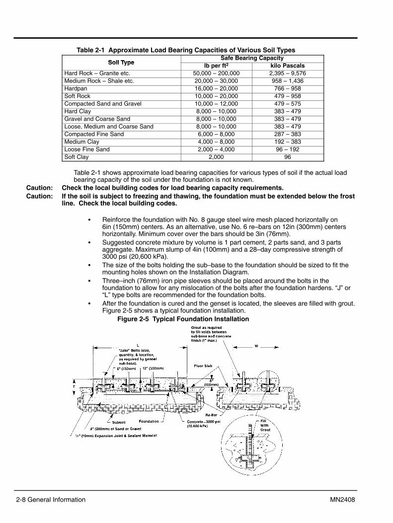
Table 2-1 Approximate Load Bearing Capacities of Various Soil Types
Soil TypeSafe Bearing Capacity
Soil Type lb per ft2 kilo PascalsHard Rock � Granite etc. 50,000 � 200,000 2,395 � 9,576Medium Rock � Shale etc. 20,000 � 30,000 958 � 1,436Hardpan 16,000 � 20,000 766 � 958Soft Rock 10,000 � 20,000 479 � 958Compacted Sand and Gravel 10,000 � 12,000 479 � 575Hard Clay 8,000 � 10,000 383 � 479Gravel and Coarse Sand 8,000 � 10,000 383 � 479Loose, Medium and Coarse Sand 8,000 � 10,000 383 � 479Compacted Fine Sand 6,000 � 8,000 287 � 383Medium Clay 4,000 � 8,000 192 � 383Loose Fine Sand 2,000 � 4,000 96 � 192Soft Clay 2,000 96
Table 2-1 shows approximate load bearing capacities for various types of soil if the actual loadbearing capacity of the soil under the foundation is not known.
Caution: Check the local building codes for load bearing capacity requirements.Caution: If the soil is subject to freezing and thawing, the foundation must be extended below the frost
line. Check the local building codes.
� Reinforce the foundation with No. 8 gauge steel wire mesh placed horizontally on 6in (150mm) centers. As an alternative, use No. 6 re�bars on 12in (300mm) centershorizontally. Minimum cover over the bars should be 3in (76mm).
� Suggested concrete mixture by volume is 1 part cement, 2 parts sand, and 3 partsaggregate. Maximum slump of 4in (100mm) and a 28�day compressive strength of3000 psi (20,600 kPa).
� The size of the bolts holding the sub�base to the foundation should be sized to fit themounting holes shown on the Installation Diagram.
� Three�inch (76mm) iron pipe sleeves should be placed around the bolts in thefoundation to allow for any mislocation of the bolts after the foundation hardens. �J� or�L� type bolts are recommended for the foundation bolts.
� After the foundation is cured and the genset is located, the sleeves are filled with grout.Figure 2-5 shows a typical foundation installation.
Figure 2-5 Typical Foundation Installation

General Information 2-9MN2408
Exhaust SystemExhaust ChecklistA. Exhaust outlets are not located upwind or near any building air intakes.B. Flexible piping section is used at engine exhaust outlet.C. Exhaust piping material is adequate for expected service.D. Exhaust piping sizing is adequate to prevent back pressure.E. Exhaust piping components are insulated as necessary to prevent operator burns and reduce pipe radiant heat losses.F. Pipe sleeves or fire proof materials are used where exhaust pipe passes through building materials as per local and state codes.G. Exhaust pipe includes rain cap or is horizontal.
The purpose of the exhaust system is to safely discharge the engine combustion products intothe atmosphere outside the building. A silencer should be installed in the exhaust system toreduce noise levels. Compliance with local noise codes is always required.
Level Of AttenuationIn general, manufacturers offer three grades of silencers: industrial, residential, and critical. Inmost cases, these grades are comparable from make to make. However, attenuation curves forthe silencer should be checked to assure the desired level of silencing is met.
System PlacementBy this time, the general genset placement within the room or building has been decided. Therouting of the exhaust system should be as direct as possible to the building exterior.
WARNING: Never allow the exhaust outlet to be positioned so that the exhaust gases are directedtowards any openings or air entry routes (doors, windows, vents, etc...) of an occupiedbuilding. When discharging the hot exhaust gases out of the building do not direct themtowards anything that could catch fire or explode.
For aesthetic reasons, consider exhaust placement in relation to the building. Over a period oftime, exhaust gas carbon deposits will tend to accumulate on any nearby wall or structure.Attention must also be given to exhaust noise in selecting placement of the exhaust system.
Multi�Engine InstallationsCaution: Do not connect multi�engine exhaust systems together. Each engine must have its own
exhaust system for proper operation.Exhaust gases from an operating engine will migrate back through a non�operating engine andcause a hydraulic lock. This may interfere with starting of the second engine. The migratinggases will also tend to turn the turbos which are not being provided lubrication if the engine is notrunning. The use of check valves in the exhaust system are discouraged due to their tendencyto �stick�.
Exhaust ManifoldThere are two exhaust manifold types. Dry type which is standard and the optional water cooled.The dry type is simply exposed to the surrounding air and becomes very hot. Shields, insulatingwraps, or other types of guards can be used to limit operator contact with the hot surfaces. Thispractice is common where engine room size is small, creating cramped conditions.Water cooled exhaust manifolds are not available on all engine models. This type manifold haspassages through which engine coolant is circulated to remove heat from the manifold surface. Italso will help protect the operator from contact with the hot manifold surface. This will reduce theamount of heat that is radiated by the engine to the surrounding air by approximately 20%. Inaddition, this type manifold significantly increases the amount of heat the cooling system mustdissipate. Marine and Mining Safety Administration (MSA) codes may require water cooledmanifolds in all genset installations. If you are in doubt on your particular application, consult yourBaldor Distributor.
Exhaust Gas RestrictionThe maximum allowable back pressure, or system restriction, is 3 inches of mercury. If this backpressure is exceeded, the air�fuel ratio is reduced due to incomplete scavenging of the cylinders,fuel economy and power output is reduced, engine life is reduced and exhaust temperatures andsmoke levels increase. Any restriction of the exhaust gas reduces horsepower. Take everyprecaution to reduce restriction. Proper design and installation will provide safe genset operation.It is essential that all engine exhaust systems by designed with the least possible restriction toexhaust gas flow. This can be calculated through the use of Figure 2-6, or in the case of simpleexhaust systems, the nomograph in Figure 2-6 may be used.

2-10 General Information MN2408
Figure 2-6 Exhaust System Calculations
Exhaust PipingCaution: The weight of the exhaust system must never be imposed on the turbo�charger outlet.
Damage to the turbo�charger and other components may result.An exhaust system must withstand the vibration and thermal expansion that they are subjectedto, yet supported well enough to remain independent of the engine.The most common method of providing flexibility is with the use of bellows type flexible piping.This piping component allows lateral and linear movement of the piping system withoutsubjecting fixed components to excessive stress. A minimum of 12 inches of flexible connectionmust be provided at the engine exhaust manifold to allow for thermal expansion and vibration. Ifthe engine is to be mounted on spring type vibration isolators, increase the length to 24 inches.This component can be specified to be provided by your Baldor distributor. Flexible pipe shouldnever be used for pipe bends or to cure misalignment problems.Exhaust piping systems may be supported by a wide variety of methods to long as the systemremains flexible, and capable of withstanding thermal expansion.The material most commonly used for straight runs and elbows in exhaust systems is Schedule40 black iron. If hanging weight is a problem, other materials may be used. Galvanized pipingshould never be used in exhaust system. Where exhaust piping passes through combustiblematerial, exhaust thimbles must be used. See Figure 2-7.
Figure 2-7 Exhaust Pipe Thimble Installation
Rain ProtectionMoisture entering the engine through an exhaust system can cause extensive damage. Exhaustoutlets must have a rain cap or be horizontal to prevent such damage. See Figure 2-7.

General Information 2-11MN2408
Cooling SystemCooling System ChecklistA. Have noise considerations been taken into account?B. Has system piping been properly sized?C. Has system been properly protected from freeze up and corrosion?D. Have standby equipment heaters been specified?E. Have all electrically driven devices been connected to load side of EPS connection points?F. Have system drain valves and air eliminators been installed?The system consists of the cooling medium which is generally a solution of water and ethyleneglycol, a method of rejecting engine produced heat, and a means to transport cooling mediumbetween the engine and heat rejection system. The first determination is the type of coolingsystem to use � radiator cooling or heat exchanger cooling.Radiator CoolingThe first and simplest is the engine mounted radiator shown in Figure 2-8. The radiator, watercirculating pump, fan and fan drive are mounted to the generator set base rails by the factory.This method of engine cooling is the most economical, but may require large ventilation ventsand ducts. An added advantage of this arrangement is that the cooling air removes radiated heatfrom the engine, generator, and other equipment located in the emergency power system room.The only remaining design work with the engine mounted radiator is arranging a method ofproviding air to the room, and exhausting it from the radiator. See �Air Systems�.
Figure 2-8 Engine Mounted Radiator Cooled System With Wind/Noise Barrier
The radiator can be mounted remotely (not mounted directly at the engine). The remote/closesystem uses the same radiator type except it is mounted in another room or outside the building,but within close proximity to the genset. See Figure 2-9.
Figure 2-9 Remote Radiator Cooled System

2-12 General Information MN2408
The remote radiator may be mounted either vertically or horizontally. In general, the radiator willhave an electric fan to provide cooling air and may be able to utilize the engine mounted coolantpump to provide coolant flow.The piping system friction and head loss between engine and radiator must be calculated andnot exceed the capacity of the engine pump. If the maximum coolant friction head loss external tothe engine is exceeded, a hot well system must be used. Before designing the piping systemusing an auxiliary pump and hot well, the consultant should look very closely at increasing thesystem�s pipe size.The electric fan and auxiliary pump, if used, must be connected to the emergency power system.Radiator and cooling fan must be sized to provide the cooling capacity required at an acceptablesound level.
Caution: In cold climates, the high volume of outside air drawn into the genset room can quicklyreduce temperatures in the room to freezing. Any water piping or other equipment susceptibleto freeze damage should be properly insulated or located elsewhere.
Heat ExchangerIn the heat exchanger system, engine coolant is circulated through the shell side of a heatexchanger, while city water, well water, or some other cooling medium, is circulated through thetube side. The primary consideration in this type cooling system is to remember that duringcertain types of disasters, these cooling mediums may not be available, especially city water. Thesystem is relatively inexpensive to install and maintenance is low. See Figure 2-10.
Figure 2-10 Heat Exchanger Cooled System
The heat exchanger cooling system can be used with a cooling tower. These systems arecomplex, and consists of circulating pumps, heat exchanger for engine coolant, and coolingtower for heat rejection. The system design requires that several pieces of equipment be sizedand installed. Overall, this system is more expensive than other methods of engine cooling.Cooling System DeterminationAfter cooling system selection, gather the required basic information before proceeding throughthis section. Information required includes engine heat rejection load, pumping capacity of theengine mounted pump, engine coolant flow requirements and pressure drop through the engine,and allowable operating temperature. This information is found on the engine data sheet.
Cooling System DesignEngine Mounted Radiator CoolingIf the engine mounted radiator is selected, the only remaining design work is arranging a methodof providing air to the room, and exhausting that air from the radiator. See �Air Systems�.

General Information 2-13MN2408
Remote Radiator CoolingRemote Radiator Airflow generally assumed there will be no external restrictions to airflow. If thisis not true, restriction must be considered in sizing and selection of a cooling fan and drive motor.Typical examples of restrictions include landscaping, nearby buildings, air turbulence created bybuildings or other structures, and sight or noise �screens�. See Figure 2-9.Remote Radiator Fan Motor. Remote radiator cooling systems require the use of an electricallydriven fan. This fan must be connected to the emergency power source. Size of the motor isdetermined by the fan size and fan speed.
1. To specify a radiator to cool the coolant you will need to determine the amount of heatrejected to the coolant. This is listed on the Engine Data Sheet as Heat Rejected toCoolant in BTU/min. for engines using dry or water cooled type exhaust manifolds, asapplicable.
2. Determine the minimum water flow required at the engine, and the maximum top tanktemperature. Using this information, determine the heat rejection capacity required ofthe radiator. Radiator systems should be sized with approximately 15% greatercapacity than the engine�s maximum full load heat rejection to allow for overload andcooling system deterioration. Whether water flow is produced by an engine mounted orauxiliary pump, total piping system friction loss must be calculated. To do this, gensetlocation, remote radiator location and friction loss within the radiator, and piping systemmust be estimated.
3. Pressure drop through the radiator must be obtained from radiator manufacturer.4. If total piping system pressure exceeds the allowable Maximum Coolant Friction Head
External to the engine as listed on the Engine Data Sheet, the coolant piping sizeshould be increased and/or a radiator with less restriction must be used.
5. Pressure drop in pipelines may be determined by the use of information in Table 2-2Figure 2-11, and friction of water tables which may be found in most mechanicalhandbooks such as �Cameron Hydraulic Data� handbook.
Table 2-2Fitting Size Flow Restriction of Fittings Expressed as Equivalent of Straight Pipe (in inches)g
1.5 2 2.5 3 4 5 6 8 10 12 14 1690 Elbow 4.4 5.5 6.5 8 11 14 16 21 26 32 37 4245 Elbow 2.5 3 3.8 5 6.3 7.5 10 13 15 17 19Long Sweep Elbow 2.8 3.5 4.2 5.2 7 9 11 14 17 20 24 27Close Return Bend 13 15 18 24 31 37 51 61 74 85 100Tee�Straight Run 3.5 4.2 5.2 7 9 11 14 17 20 24 27Tee�Side Inlet or Outlet 9.3 12 14 17 22 27 33 43 53 68 78 88Globe Valve Open 55 67 82 110 140Angle Valve Open 27 33 41 53 70Gate Valve Fully Open 1.2 1.4 1.7 2.3 2.9 3.5 4.5 5.8 6.8 8 9Gate Valve Half Open 27 33 41 53 70 100 130 160 200 230 260Check Valve 19 23 32 43 53
Hot Well InstallationsOne final consideration on the water side is the Maximum Static Head. This is the maximumheight allowable from the engine crank center line to the highest point in the coolant system. Themaximum static head is specified on generator specification sheets. If this number must beexceeded, a hot well tank system must be used. A typical example is shown in Figure 2-12.The design of hot well tanks and piping systems is somewhat complex. Your authorized BaldorDistributor has experience in the design and installation of hot well systems. Consult your BaldorDistributor if the static head of the coolant system in your genset application exceeds this criteriaand requires a hot well system.

2-14 General Information MN2408
Figure 2-11 Valves & Fittings and Fluid Flow in Pipe
Figure 2-12 Hot Well Installation

General Information 2-15MN2408
Other ConsiderationsGeneral:
1. Deaeration of the coolant. This can be accomplished through the use of the systemdeaerators in very large systems, or simply ensuring the radiator top tank or surge tankis at the highest point in the piping system. Unvented piping systems can create airpockets which reduce coolant flow and can lead to engine overheating. Baldorfurnished radiators are equipped with deaerating top tanks.
2. Flexible hoses must be installed at all engine connections and to the radiator to isolatevibration and allow for thermal expansion.
3. Drain valves must be installed at the lowest point of the cooling system to facilitatesystem cleaning and flushing.
4. Water treatment and antifreeze must be added to system coolant. Baldor recommends50/50 ethylene glycol and coolant treatment for all engines.
5. Thermostatically controlled engine coolant heaters are required to be installed on allstandby gensets. These will increase starting reliability under cold conditions, andimprove the start�up load handling ability.
6. According the NFPA 110, priority level 1 equipment jacket water heaters shall maintaincoolant at a minimum of 90 °F (32 °C). In outdoor installations where temperatures willbe expected to drop below 32 °F (0 °C), a battery heater should be employed to keepthe batteries at a minimum of 50 °F (10 °C), and will shut off at 90 °F (32 °C). All heaters will shut off when the engine is operating. Adequate antifreeze protectionwill be provided and ether starting aids will not be permitted.
7. The consultant should also consider oil sump heaters if conditions warrant.
Heat Exchanger Cooling:1. If the engine is to be heat exchanger cooled, the system will require a reliable raw
cooling water source and controls to regulate water flow during genset operation.2. The system will also need a reliable method of starting and stopping water flow
automatically. The heat exchanger cooled system may be used with a cooling tower.3. Baldor Gensets are available with heat exchangers sized and mounted on the engine
by the factory. If a heat exchanger cooled system is required, specify with order.4. Shell and tube type heat exchangers are connected such that raw cooling water flows
through the tube side of the heat exchanger, and engine coolant through the shell side.Tubes are more easily cleaned and the potential for fouling is much greater on the rawwater side.
5. For economic reasons, the raw water flow can be regulated by varying the flow of rawcooling water through the heat exchanger. This control can be accomplished with atemperature actuated control valve. The thermostatic bulb for this control must be inthe engine jacket water discharge line. The control valve should be a fully modulatedtype with a minimum flow setting. NEVER attempt to regulate engine water flow.
6. Water flow regulators are used only if raw water is from a city or well water source. Donot attempt to regulate flow if a cooling tower is used. Maintain at least 2 ft/second ofwater flow through the tube side of the heat exchanger.
7. Heat exchanger cooled systems using city or well water, and cooling, tower heatrejection, however, will not be protected on the tube side of the heat exchanger, norinterconnecting piping and cooling tower as engine coolant is not circulated throughthese components. These systems must be heat traced, and have sump heatersinstalled to protect the various components when the genset is on standby.
It must also be noted that if an antifreeze solution is used in the shell side of the enginecooling system heat exchanger, local codes may restrict the discharge of the tube sidecooling water after flowing through the heat exchanger.

2-16 General Information MN2408
Coolant Treatment: See Figure 2-13.1. Engine coolant should be treated with a Diesel Coolant Additive (DCA) to minimize
corrosion of the engine and cooling system components. A 50/50 ethylene glycolantifreeze solution is recommended for all genset engines. This will provide freezeprotection and increase the boiling point of the engine coolant. A solution can beincreased to 65%. Do not exceed 65% as freeze protection begins to diminish at 65%.
2. It is recommended that the consultant specify Baldor supplied DCA and water filters,and Baldor antifreeze.
3. When the proper solution concentration of antifreeze is used with radiators (enginemounted as well as remote mounted), and hot well systems, the system will beadequately protected from freeze�up.
Figure 2-13 Coolant Mixture

General Information 2-17MN2408
Air System Air System ChecklistA. Air inlet faces the direction of prevailing winds.B. Air outlet does not face noise sensitive areas without noise attenuating devices.C. All heat loads have been taken into consideration in sizing air flow.D. Gravity louvers face inward for air intake and outward for discharge.E. Where electrically operated ventilation devices are used, power must be present under all operating situations. Be certain these devices are on the emergency circuit.
The room in which the generator set is to be installed must have adequate air flow through it toprovide combustion air, and remove heat radiated from the engine, exhaust system andgenerator. See Figure 2-14 for air flow calculations.
Figure 2-14 Air Flow Calculations
Radiator CoolingThe engine mounted radiator shown in Figure 2-8. With an engine mounted radiator coolingsystem, air movement is provided by the engine driven radiator fan. The consultant must designthe inlet and outlet duct work and louvers to accommodate the air flow required. The radiator fanis limited in the amount of external static pressure it will tolerate. The maximum air restriction onthe discharge side of the radiator is shown under the heading of Cooling System on the EngineData Sheets. Cooling fan air flow is listed under Engine Data by dry type and water cooledexhaust manifold for 100 °F and 125 °F cooling systems.
The ideal setup for cooling air would be to arrange the inlet or inlets such that relatively clean,cool, dry air is drawn across the electrical switchgear, generator, and engine. The air is thendrawn into the radiator fan, and is blown through the radiator and exhausted by duct work outsidethe building. Air inlets must be sized to minimize air restriction and provide the quantity of airrequired by the radiator fan, engine combustion air, and any other air exhausts which might beused in the room. On engine mounted radiator cooled systems, the engine mounted fan willhandle 0.25� of water column. This is combined intake and exhaust restriction.
The room air intakes must be located so as to minimize drawing exhaust fumes and otheroutside contaminants into the room. Be very cautious about the location of the engine exhaustsin relation to room air intakes. Also, when locating the inlet and outlet, the consultant shouldconsider prevailing winds and noise. Motor operated louvers or properly designed and sizedgravity louvers should be used on the air intake and exhaust to minimize static pressure drop.
Electric motorized louvers used with engine mounted radiators should be connected to thestandby genset and controlled to open whenever the genset is running. Operable outlet louversshould be temperature actuated on remote radiator or heat exchanger cooled units. Louvershave resistance to air flow. Openings with louvers should be twice the area of an unobstructedopening to provide proper air flow. At times duct work is necessary to provide cooling air for theroom, see Figure 2-15. Duct work must be sized and installed according to SMACNA Standards.
Wind BarrierWind blowing against air exhaust or intake openings of the genset room must be considered,especially where the radiator and fan are located on the engine. Wind blowing against anexhaust opening creates restriction to the fan. Wind blowing against intake openings can blowopen gravity louvers causing low temperature and moisture problems in bad weather.

2-18 General Information MN2408
Figure 2-15 Radiator Cooling with Ducted Air Handling
Other Engine Cooling SystemsRemote radiator and heat exchanger cooled engine cooling systems will not have an enginedriven fan. As a result, the consultant must provide a means of supplying air to the room, andexhausting it. The air movement must be provided by an electrically driven fan. This fan may belocated in the air inlet or exhaust opening. If the fan is located on the exhaust side, care must betaken to not create a high negative pressure in the room and starve the engine of combustion air.If the fan is located in the air inlet, it must be noted that odors may be forced into other parts ofthe building if the room is not properly sealed. This electrically driven fan must be connected soas to run whenever the generator is operating. Any fans for the engine room should be on theemergency circuit. An example may be seen in Figure 2-16.
Figure 2-16
Engine Crankcase VentilationFor gensets operating more than 1000 hours per year, the engine crankcase breather should bevented upward and outside of the engine room. This prevents the buildup of oil vapors inside thebuilding.

General Information 2-19MN2408
Transfer SwitchTransfer Switch ChecklistA. Locate transfer switch in a clean, dry place, near the emergency load.B. Provide a circuit breaker between the genset and the transfer switch.C. Put a flexible connection between the conduit and genset.D. Observe applicable codes in wiring�in the transfer switch and genset.
The transfer switch connects the genset to the emergency power system. The emergency powersystem may include several gensets and several transfer switches. Typically, the genset is wiredto the emergency power system through a transfer switch as shown in Figure 2-17.
Figure 2-17 Typical Emergency power System Installations
Multiple Gensets can be arranged either in parallel or separately connected to dedicatedemergency loads. Figure 2-17 also shows a typical arrangement of two gensets in parallel withtransfer switches for loads that have different levels of priority. A typical multiple gensetinstallation is shown for NFPA 110 Level 1 and Level 2 emergency power circuits and a prioritycontrol to select the appropriate transfer switch.Wattmeters should be installed on each genset so load sharing can be checked. The controlsystem should include an automatic paralleling control. Paralleling identical gensets is notdifficult, but paralleling dissimilar sets can cause load sharing problems. When designing aninstallation that includes the paralleling of dissimilar generators, contract your nearby BaldorDistributor.
Transfer Switch LocationThe transfer switch location is important and key considerations are:
1. Locate the transfer switch as close to the emergency load as practical to avoidinterruptions of the emergency power system due to natural or man�made disasters, orto equipment failures. Consider several small transfer switches instead of one largeone to increase reliability.
2. Locate the transfer switch in a clean, dry, well ventilated location, away from excessiveheat. When the ambient air is above 104 °F (40 °C), fuses and circuit breakers must bederated. Allow adequate working space around the transfer switch.
3. A circuit breaker (or fuses) should be installed in the line between the generator andthe transfer switch. Baldor Gensets are available with properly sized circuit breakerbuilt into the generator control through 1200 amp breakers. The circuit breaker can beseparately mounted. In the case of very large circuit breakers, a separate floormounted circuit breaker is easier to wire up than a wall mounted breaker.
4. Install power and control wires in separate solid conduit with flexible sections at thegenset. The flexible sections prevent vibration from damaging the conduit. All powerconduits from the genset must contain all three phases.
5. Never install control wires in the same conduit as power conductors.

2-20 General Information MN2408
6. Conduit, wire, circuit protective device sizes, insulation etc. must conform to applicablelocal and national codes and regulations.
7. Be certain to seal around conduits that penetrate the walls of the genset room toreduce the amount of noise that is transmitted to the surrounding areas of the buildingand maintain site fire code rating.
Battery Starting SystemThis section describes the battery starting system (nominal 12 volt rating of the battery supply)for the engine, battery charger, and precautions to take if the ambient temperature is expected tobe below 70 °F (20°C).
WARNING: If batteries are not mounted in the battery rack supplied with the genset, protect batteriesfrom vibration and do not locate them near a source of flame or spark. A battery presents arisk of fire and explosion because they generate hydrogen gas. Hydrogen gas is extremelyexplosive. Never jump start a battery, smoke in the area around the battery or cause anyspark to occur in the area around the battery.
Battery LocationLocate batteries as close as possible to the genset to minimize starting circuit resistance, seeFigure 2-18. High starting circuit resistance substantially reduces starting cranking ability. Thegenset data sheet lists the maximum allowable cranking system resistance. Mount batteries on alevel rack away from dirt and liquids. Allow space for servicing (checking water level and level ofcharge). Baldor gensets can be ordered with battery racks already installed. Cold ambienttemperature at the battery location substantially reduces the battery output.
Figure 2-18 Battery Starting System
Battery SizeThe ability to start the engine depends upon battery capacity, ambient temperature and coolantand oil temperatures. The Engine/Generator Set Data Sheet lists minimum recommended batterycapacity at various ambient temperatures. The recommended battery capacities are listed in theElectric Systems section of the Engine Data Sheet, cold cranking amps (CCA) at 0 °F (�18 °C).Battery capacities decrease as ambient temperatures decrease so it is important to specifybatteries with the appropriate CCA rating at a temperature no higher than the minimum ambienttemperature for the application. Baldor requires thermostatically controlled coolant heaters on allafter cooled standby gensets. After cooling is called out on the Engine Data Sheet under GeneralEngine Data section as �aspiration�.Oil pan immersion heaters are recommended for standby gensets housed outside where ambienttemperatures may drop below 0 °F (�18 °C). Coolant heaters and oil pan immersion heaters areavailable from Baldor as factory installed options.

General Information 2-21MN2408
Battery ChargerAn engine mounted alternator to charge the batteries during operation is an available option.Standby gensets require a solid state battery charger that is connected to utility power so thebattery is charged continuously while the genset is not running. The battery charger should beconnected to the emergency circuit. The batteries on prime power gensets are charged by theengine mounted alternator, if equipped.Harmonic wave forms from solid state battery charges and belt driven alternators can cause theelectronic governor on the engine to act erratically. To avoid this, the output of the battery chargeror the belt driven alternator must be connected directly to the battery or to the battery terminalson the starter. Make control connections to the genset control using a conduit with a flexiblesection at the genset to avoid damage due to genset vibrations.
Battery CablesThe wire size (wire gauge) of the cables connecting the starter to the batteries must be largeenough to ensure the resistance of the cranking circuit is less than the �Maximum AllowableResistance of the Cranking Circuit� as shown on the Engine�Generator Set Data Sheet. The totalcranking circuit resistance includes the resistance of the cables from the starting motor to thebattery and the resistance of all relays, solenoids, switches, and connections. The resistance ofvarious sizes of cables is shown in Figure 2-19. For purposes of calculating cranking circuitresistance to select cable size, the resistance of each connection can be taken as .00001 ohmsand the resistance of each relay, solenoid, and switch can be taken as .0002 ohms. Figure 2-19illustrates an example of a typical cranking circuit resistance calculation.
Figure 2-19 Typical Battery Cable Calculations

2-22 General Information MN2408

Section 3Receiving & Installation
Receiving & Installation 3-1MN2408
Receiving & Inspection When you receive your generator, there are several things you should do immediately.1. Observe the condition of the shipping container and report any damage immediately to
the commercial carrier that delivered your system.2. Verify that the part number of the system you received is the same as the part number
listed on your purchase order.3. If the system is to be stored for several weeks before use, be sure that it is stored in a
location that conforms to published storage temperature and humidity specifications.Lifting the Generator When lift or hoist equipment is used to lift the generator and move it to position, be careful not
to contact overhead wires or other obstacles. The generator can weigh as much as 3,000 lbs. Besure lift or hoist equipment has appropriate tires for the terrain to avoid becoming stuck or tippingover. If the shipping pallet is intact, use a fork lift to move the generator. If the shipping pallet hasbeen removed, use two steel pipes through the �Lift Point� holes to lift the generator. See Figure 3-1.
Figure 3-1 Generator Lifting
Lift Point
LiftPoint
Height
Width
Length
To lift the generator, always use spreader bars,chains eyehooks and other hardware that is ofsufficient strength to lift at least three times theweight of the generator.
Physical Location The mounting location of the system is important. It should be installed in an area that isprotected from direct harmful gases or liquids, dust, metallic particles, shock and vibration. It should be installed in an outdoor location so the exhaust fumes are vented to the atmosphere.
When the Generator is installed outdoorsIf the generator is installed outdoors there should not be a cooling problem. The factory installedenclosure is designed to keep out undesirable weather elements while providing cooling andventilation.
When the Generator is installed in a building it is essential to provide:1. Adequate control and exhausting of the heated air.2. An adequate and constant supply of incoming cooling air.3. Adequate control and discharge of the engine�s hot exhaust gases.4. Adequate ventilation of the building when the engine shuts down.

3-2 Receiving & Installation MN2408
WARNING: An open bottom stationary engine generator set must be installed over noncombustiblematerials and shall be located such that it prevents combustible materials from accumulatingunder the generator set.
Several other factors should be carefully evaluated when selecting a location for installation:1. For effective cooling and maintenance, the system should be mounted on a flat,
smooth, noncombustible level surface. A concrete pad is ideal and provides a secureinstallation.
2. Installation should prevent water levels from reaching the generator. Drainage must beadequate to keep concrete pad free from standing water.
3. Installation should prevent obstructions by buildup of leaves, grass, sand, snow, etc. Ifthese items pose a problem, consider building a small fence or other break to protectthe unit from accumulation of debris.
4. Installation should place the generator as close as possible to the fuel supply andtransfer switch.
5. At least forty�eight (48) inches clearance must be provided on all sides for air flow.6. Access must be provided to allow the enclosure covers to be opened or removed for
service and maintenance.7. Maximum Ambient temperature is 122°F (50°C).
Figure 3-2 Generator Mounting
��
����������� ����
��
� ������ �����������������������
�
�
�� ��
�� ��
��
��
�
������������ ��������
������������������������ �������� �������������!�"
Table 3-3 Mounting DimensionsGenerator A A1 A2 B B1 B2 E1 F1
GLC30 78.0 6.0 33.0 44.0 42.5 6.25 17.0 32.0GLC35 78.0 6.0 33.0 44.0 42.5 6.25 17.0 32.0GLC45 78.0 6.0 33.0 44.0 42.5 6.25 17.0 32.0GLC50 118.0 6.0 38.0 44.0 42.5 6.25 17.0 32.0GLC60 118.0 6.0 38.0 44.0 42.5 6.25 17.0 32.0GLC80 118.0 6.0 38.0 44.0 42.5 6.25 17.0 32.0
GLC100 118.0 6.0 38.0 44.0 42.5 6.25 17.0 32.0GLC125 118.0 6.0 38.0 44.0 42.5 6.25 17.0 32.0

Receiving & Installation 3-3MN2408
Secure the GeneratorSix (eight for the GLC125) mounting bolts in the base frame secure the generator to the shippingpallet. Remove these bolts, lift the generator and remove the shipping pallet. Secure thegenerator to the concrete pad using 3/8″ anchor hardware (not provided) in the base framemounting holes. See Figure 3-2. Anchor bolts must be long enough to extend through thegenerator mounting frame.
Engine Cooling A sufficient flow of clean, cool air is required for combustion and to dissipate the heat producedby the engine. Approximately 60% of the heat value of the fuel used is given off as heat (coolingair and exhaust).The air that will cool the engine must be brought in from outside the building. A sufficient air�flowof rate �Cubic Feet per Minute� (CFM) will allow the incoming fresh air to cool the engine. Thisrequires a power ventilation system of sufficient CFM to be located at the highest possible pointof the building to exhaust hot air and draw in cool fresh air.Note: The exhaust fan must not be located where it could easily become blocked by leaves,
snow, water, debris, etc.It is recommended that the cool air intake have at least three (3) times the cross�sectional areaof the power ventilation system. It is also recommended that the cool air intake be located asclose as possible to the top of the generator set.The exhaust fan must be connected to the AC power terminals of the generator set so that whenthe generator set starts it will provide immediate cooling air flow. The fan will operate until thegenerator set stops. To test the ventilation system, do the following:Ventilation Test
1. Place a thermometer as close to the cool air intake of the engine�s blower housing asyou can without allowing the thermometer to touch any material surface.
2. Place another thermometer outside of the building or compartment in the open air(Keep the thermometer out of direct sunlight or any other heat sources).
3. Run the engine under maximum load for an extended period of time (at least one hour).4. The temperature difference between the two should not exceed 15 degrees F.
Note that opening any door, window or other opening can upset the air�flow pattern and result ina significant reduction in the cooling air�flow across the generator set. This may result inoverheating, fire, or explosion. To find out if this is true with your specific application run theVentilation Test with all doors and windows closed. Then repeat this test with different doors andwindows open, and eventually with all the windows and doors open. If any of these tests result ina temperature difference in excess of 15° F, you must not run the generator set under thosespecific conditions.
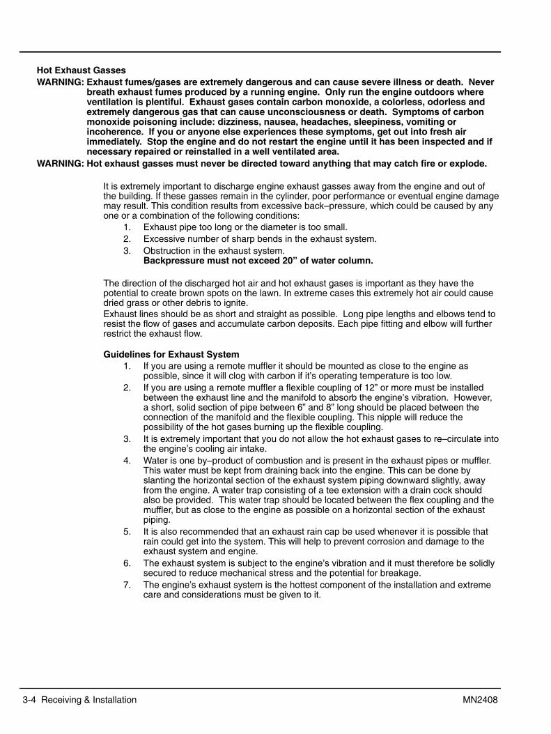
3-4 Receiving & Installation MN2408
Hot Exhaust GassesWARNING: Exhaust fumes/gases are extremely dangerous and can cause severe illness or death. Never
breath exhaust fumes produced by a running engine. Only run the engine outdoors whereventilation is plentiful. Exhaust gases contain carbon monoxide, a colorless, odorless andextremely dangerous gas that can cause unconsciousness or death. Symptoms of carbonmonoxide poisoning include: dizziness, nausea, headaches, sleepiness, vomiting orincoherence. If you or anyone else experiences these symptoms, get out into fresh airimmediately. Stop the engine and do not restart the engine until it has been inspected and ifnecessary repaired or reinstalled in a well ventilated area.
WARNING: Hot exhaust gasses must never be directed toward anything that may catch fire or explode.
It is extremely important to discharge engine exhaust gasses away from the engine and out ofthe building. If these gasses remain in the cylinder, poor performance or eventual engine damagemay result. This condition results from excessive back�pressure, which could be caused by anyone or a combination of the following conditions:
1. Exhaust pipe too long or the diameter is too small.2. Excessive number of sharp bends in the exhaust system.3. Obstruction in the exhaust system.
Backpressure must not exceed 20� of water column.
The direction of the discharged hot air and hot exhaust gases is important as they have thepotential to create brown spots on the lawn. In extreme cases this extremely hot air could causedried grass or other debris to ignite.Exhaust lines should be as short and straight as possible. Long pipe lengths and elbows tend toresist the flow of gases and accumulate carbon deposits. Each pipe fitting and elbow will furtherrestrict the exhaust flow.
Guidelines for Exhaust System1. If you are using a remote muffler it should be mounted as close to the engine as
possible, since it will clog with carbon if it�s operating temperature is too low.2. If you are using a remote muffler a flexible coupling of 12� or more must be installed
between the exhaust line and the manifold to absorb the engine�s vibration. However,a short, solid section of pipe between 6� and 8� long should be placed between theconnection of the manifold and the flexible coupling. This nipple will reduce thepossibility of the hot gases burning up the flexible coupling.
3. It is extremely important that you do not allow the hot exhaust gases to re�circulate intothe engine�s cooling air intake.
4. Water is one by�product of combustion and is present in the exhaust pipes or muffler.This water must be kept from draining back into the engine. This can be done byslanting the horizontal section of the exhaust system piping downward slightly, awayfrom the engine. A water trap consisting of a tee extension with a drain cock shouldalso be provided. This water trap should be located between the flex coupling and themuffler, but as close to the engine as possible on a horizontal section of the exhaustpiping.
5. It is also recommended that an exhaust rain cap be used whenever it is possible thatrain could get into the system. This will help to prevent corrosion and damage to theexhaust system and engine.
6. The exhaust system is subject to the engine�s vibration and it must therefore be solidlysecured to reduce mechanical stress and the potential for breakage.
7. The engine�s exhaust system is the hottest component of the installation and extremecare and considerations must be given to it.

Receiving & Installation 3-5MN2408
8. As much of the exhaust piping as possible should be located near the power ventilationexhaust. This will reduce the radiant exhaust heat inside the building.
9. Keep all fuel and its associated piping away from all components of the engine exhaustsystem.
10. After the exhaust system is installed it should be inspected on a regular basis to assurethere are no toxic exhaust gas leaks. In some areas this inspection may be provided byyour local public service.
11. A carbon monoxide tester may be installed to detect the presence of the deadly gasduring times when you are in the building with the engine running (during testing ormaintenance).
WARNING: Never allow the exhaust outlet to be positioned so that the exhaust gases are directedtowards any openings or air entry routes (doors, windows, vents, etc...) of an occupiedbuilding. When discharging the hot exhaust gases out of the building do not direct themtowards anything that could catch fire or explode.
WARNING: Exhaust fumes/gases are extremely dangerous and can cause severe illness or death. Neverbreath exhaust fumes produced by a running engine. Only run the engine outdoors whereventilation is plentiful. Exhaust gases contain carbon monoxide, a colorless, odorless andextremely dangerous gas that can cause unconsciousness or death. Symptoms of carbonmonoxide poisoning include: dizziness, nausea, headaches, sleepiness, vomiting orincoherence. If you or anyone else experiences these symptoms, get out into fresh airimmediately. Stop the engine and do not restart the engine until it has been inspected and ifnecessary repaired or reinstalled in a well ventilated area.

3-6 Receiving & Installation MN2408
Installation The generator is completely assembled, tested and adjusted at the factory before it is shipped toyou. The procedures presented in this manual are suggestions and it is the responsibility of theOwner/Operator to arrange for these procedures to be performed by licensed contractorsaccording to all applicable codes including local codes for your Municipality/City/County andState. External connections required at the time of installation are:
1. Fuel System.2. Electrical Connections � power wiring (optional transfer switch) and control wiring.3. Battery (not included).4. Ground Connection.
After installation, the post installation checks must be performed prior to starting the engine.After these checks have been performed and the system operation is verified to be good, refer toSection 5 Maintenance for periodic checks that must be performed at scheduled intervals toensure continued operation with minimal problems.
Fuel ConnectionsFuel selection is Natural Gas or LPG (Liquid Propane Gas). If natural gas supply is used, followthe �Natural Gas Connections� procedure. If LPG supply is used, follow the �LP GasConnections� procedure. Table 3-4 defines the flow rate required for each fuel type.
Table 3-4 Fuel Consumption Natural and LPGGenerator Model Fuel Consumption at 100% load (cubic feet per hour)
Natural Gas LP GasGLC30 14.9 5.6GLC35 16.3 6.0GLC45 16.5 6.9GLC50 20.7 8.2GLC60 22.1 9.1GLC80 28.7 12
GLC100 32.1 13.8GLC125 46.8 16.5
General Considerations1. A generator set needs the engine to deliver 2 hp of energy to the alternator for every
1000 watts of electric output power (example: an 8000 watt generator needs the engineto deliver 16 hp of energy to the generator end).
2. An engine needs 10,000 BTU�s of fuel energy per horsepower of engine power toprovide a sufficient supply of fuel (example: a 16 Hp engine needs 160,000 BTU�s offuel energy for it to work properly). This fuel must be supplied to the regulator on thegenerator set at a pressure of 6 oz (11 inches of water column). To achieve this 6 oz.pressure in a L.P. System, you will normally have to reduce the tank pressure bymeans of a primary regulator or a regulator system of 2 or more regulators.
3. There are 2,516 BTU�s in one cubic foot of Propane (LP Fuel).There are 1,096 BTU�s in one cubic foot of Natural Gas.
4. There are 36.39 cubic feet in one gallon of Propane.There are 57.75 cubic feet in one gallon of Natural Gas.
5. There are 8.58 cubic feet per pound of Propane.There are 23.56 cubic feet per pound of Natural Gas.
6. When installing the piping for the gaseous fuel supply please refer to the pipe chart inTables 3-5 and 3-6 to be sure you are using piping of significantly large size to deliverthe necessary amount of fuel.
7. If copper tubing is used, it should be �K� or �L� having a minimum wall thickness of0.032 inches. Black Iron Pipe is recommended but follow building codes for your area.
The following pamphlets are available from:National Fire Protection Association (NFPA) P.O. Box 9101 Quincy, MA 02269
No. 37 � Combustion EnginesNo. 54 � Gaseous Appliances and pipingNo. 58 � Storage and handling LPG

Receiving & Installation 3-7MN2408
Example: Determining Pipe Size for Natural GasA generator has a 16Hp engine 60 feet from the supply. Determine the supply pipe size for Natural Gas fuel.16 x 10,000 = 160,000 BTU�s / per hour for proper operation.160, 0001, 096
� 146 cubic feet per hour.
From Table 3-6, a 60 foot run requires a minimum 1� pipe at full engine load.
Natural Gas ConnectionsThe incoming pressure must be 11 inches water column (6 oz. pressure).
Table 3-5 Natural Gas Flow Rate (Cubic Feet per Hour) per Pipe LengthPipe
LengthIron Pipe Size
Length(Feet)
1/2″ 3/4″ 1″ 1�1/4″ 1�1/2″ 2″ 2�1/2″ 3″ 4″ 6″ 8″15 73 165 332 722 1174 2386 3704 6253 13352 3722930 50 115 232 515 818 1712 2646 4521 9331 26330 5372845 41 95 191 418 673 1419 2213 3752 7600 22462 4386760 37 83 166 366 587 1241 1924 3319 6542 18595 3799975 74 149 332 524 1077 1684 2886 5772 16652 3395990 67 137 298 433 962 1501 2597 5291 15200 31025
105 63 126 274 885 1376 2357 4906 14064 28715120 115 260 404 827 1289 2213 4618 13160 26859150 105 233 366 750 1174 2011 4185 11775 24050180 96 216 337 693 1077 1876 3848 10736 21934210 89 197 308 635 991 1712 3559 9937 20298240 183 289 596 933 1616 3357 9235 18990270 171 274 558 875 1520 3127 8658 17903300 164 260 524 827 1433 2886 8177 16998
Note: Almost all operation problems are related to the installation techniques used. Do Notguess, be sure pipe size is adequate for required flow rate.
1. Connect the proper size gas pipe at the Inlet Connection to the Fuel Lock Solenoid.Connect the Natural Gas pipe line shown in Figure 3-3 using the correct size pipe forthe required flow rate and length of pipe. Refer to Table 3-5 for pipe size. Be certainthat all connections are sealed and no leaks are present. The installer must ensurethat all gas connections comply with all building codes.
2. Verify Fuel Supply PressurePrior to initial operation of generator, verify that fuel system pressure is 11″ WaterColumn (6 oz. pressure) and fuel pipe sizes comply with Table 3-5.
3. Proceed to Electrical Connections.Figure 3-3 Gas Line Connections
������� �� ������!
"��������������
���������
��� �����
#� ���$����!�� ��������%�&����'��(��) ��''�%�&��
� ���(�*��$
�+�+���, ��-��-������-) ��''��&�&�������$ ������������-���������)��- ���(����$������������)��$-�- ���(�����)��$�������+
��������.�$ ���������/��01�2������� 3�����-- ���
�����!������"�#$$!����(��-������
4��"��������������

3-8 Receiving & Installation MN2408
Example: Determining Pipe Size for LPGA generator has a 16Hp engine 60 feet from the supply. Determine the supply pipe size for Natural Gas fuel.16 x 10,000 = 160,000 BTU�s / per hour for proper operation.160, 0002, 516
� 63.5 cubic feet per hour.
From Table 3-6, a 60 foot run requires a minimum 1� pipe at full engine load.
LP Gas Connections (vapor withdrawal only)The LPG connections should only be made if your generator is setup to run on LPG. If it is setupto run on Natural Gas, contact your Baldor representative and do not continue with installation.
The incoming pressure must be 11 inches water column (6 oz. pressure).Table 3-6 LP Gas Flow Rate (Cubic Feet per Hour) per Pipe Length
PipeLength
Iron Pipe SizeLength(Feet)
1/2″ 3/4″ 1″ 1�1/4″ 1�1/2″ 2″ 2�1/2″ 3″ 4″ 6″ 8″15 48 109 218 475 772 1570 2437 4115 8786 24497 5000730 33 76 153 339 538 1127 1741 2975 6140 17325 3535345 27 63 126 275 443 934 1456 2469 5001 14781 2886560 24 54 110 241 386 817 1266 2184 4304 12236 2500475 49 98 218 345 709 1108 1899 3798 10957 2234590 44 89 196 310 633 987 1709 3482 10001 20414
105 41 83 180 285 582 905 1551 3228 9254 18895120 76 171 266 544 848 1456 3038 8659 17673150 69 153 241 494 772 1323 2754 7748 15825180 63 142 222 456 709 1234 2532 7064 14432210 58 130 202 418 652 1127 2342 6439 13356240 120 190 393 614 1063 2209 6077 12405270 113 180 367 576 1000 2057 5697 11780300 108 171 345 544 943 1899 5381 11179
Note: Almost all operation problems are related to the installation techniques used. Do Not guess, be sure pipe size is adequate for required flow rate.
1. Connect the proper size gas pipe at the input to the LP Gas regulator. Connect theLPG pipe line shown in Figure 3-3 using the correct size pipe for the required flow rateand length of pipe. Refer to Table 3-6 for pipe size. Be certain that all connections aresealed and no leaks are present. The installer must ensure that all gas connectionscomply with all building codes.
2. Verify Fuel Supply PressurePrior to initial operation of generator, verify that fuel system pressure is 11″ WaterColumn (6 oz. pressure) and fuel pipe sizes comply with Table 3-6.
3. Proceed to Electrical Connections.
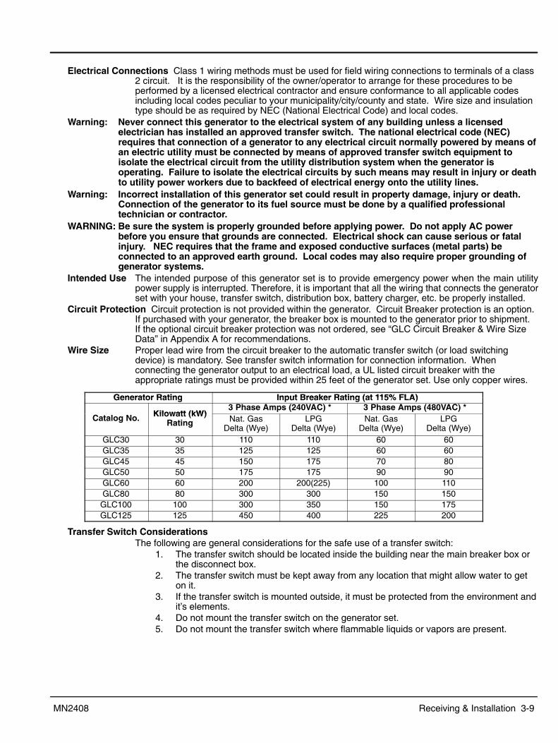
Receiving & Installation 3-9MN2408
Electrical Connections Class 1 wiring methods must be used for field wiring connections to terminals of a class2 circuit. It is the responsibility of the owner/operator to arrange for these procedures to beperformed by a licensed electrical contractor and ensure conformance to all applicable codesincluding local codes peculiar to your municipality/city/county and state. Wire size and insulationtype should be as required by NEC (National Electrical Code) and local codes.
Warning: Never connect this generator to the electrical system of any building unless a licensedelectrician has installed an approved transfer switch. The national electrical code (NEC)requires that connection of a generator to any electrical circuit normally powered by means ofan electric utility must be connected by means of approved transfer switch equipment toisolate the electrical circuit from the utility distribution system when the generator isoperating. Failure to isolate the electrical circuits by such means may result in injury or deathto utility power workers due to backfeed of electrical energy onto the utility lines.
Warning: Incorrect installation of this generator set could result in property damage, injury or death.Connection of the generator to its fuel source must be done by a qualified professionaltechnician or contractor.
WARNING: Be sure the system is properly grounded before applying power. Do not apply AC powerbefore you ensure that grounds are connected. Electrical shock can cause serious or fatalinjury. NEC requires that the frame and exposed conductive surfaces (metal parts) beconnected to an approved earth ground. Local codes may also require proper grounding ofgenerator systems.
Intended Use The intended purpose of this generator set is to provide emergency power when the main utilitypower supply is interrupted. Therefore, it is important that all the wiring that connects the generatorset with your house, transfer switch, distribution box, battery charger, etc. be properly installed.
Circuit Protection Circuit protection is not provided within the generator. Circuit Breaker protection is an option.If purchased with your generator, the breaker box is mounted to the generator prior to shipment.If the optional circuit breaker protection was not ordered, see �GLC Circuit Breaker & Wire SizeData� in Appendix A for recommendations.
Wire Size Proper lead wire from the circuit breaker to the automatic transfer switch (or load switchingdevice) is mandatory. See transfer switch information for connection information. Whenconnecting the generator output to an electrical load, a UL listed circuit breaker with theappropriate ratings must be provided within 25 feet of the generator set. Use only copper wires.
Generator Rating Input Breaker Rating (at 115% FLA)Generator Rating Input Breaker Rating (at 115% FLA)
Kilowatt (kW)3 Phase Amps (240VAC) * 3 Phase Amps (480VAC) *
Catalog No. Kilowatt (kW)Rating Nat. Gas
Delta (Wye)LPG
Delta (Wye)Nat. Gas
Delta (Wye)LPG
Delta (Wye)GLC30 30 110 110 60 60GLC35 35 125 125 60 60GLC45 45 150 175 70 80GLC50 50 175 175 90 90GLC60 60 200 200(225) 100 110GLC80 80 300 300 150 150
GLC100 100 300 350 150 175GLC125 125 450 400 225 200
Transfer Switch ConsiderationsThe following are general considerations for the safe use of a transfer switch:
1. The transfer switch should be located inside the building near the main breaker box orthe disconnect box.
2. The transfer switch must be kept away from any location that might allow water to geton it.
3. If the transfer switch is mounted outside, it must be protected from the environment andit�s elements.
4. Do not mount the transfer switch on the generator set.5. Do not mount the transfer switch where flammable liquids or vapors are present.

3-10 Receiving & Installation MN2408
Figure 3-4 Three Phase WYE and DELTA Connections

Receiving & Installation 3-11MN2408
Battery Charger Considerations1. Mount the battery charger on the generator or as close to the generator as possible.2. If you mount the battery charger inside the building, mount it near the main breaker box
or disconnect box.3. If you mount the battery charger outside, you must protect it from the environment and
the elements.4. Do not mount the battery charger where flammable liquids or vapors are present.
General Wiring Considerations1. When routing the interface wiring, do not route it up against anything that could cut or
chafe the wiring. do not route the wire up against any hot or potentially hot object.2. Make sure that all the electrical components (generator set, transfer switch, battery
charger, etc.) share a common hard wired ground.3. Check with your local building inspector to determine what you must do to comply with
the local regulations for grounding of this type of permanent installation.
Frame Ground ConnectionWARNING: Be sure the system is properly grounded before applying power. Do not apply AC power
before you ensure that grounds are connected. Electrical shock can cause serious or fatalinjury. NEC requires that the frame and exposed conductive surfaces (metal parts) beconnected to an approved earth ground. Local codes may also require proper grounding ofgenerator systems.
It is important for safety reasons that the Generator set, transfer switch and battery charger sharea common Ground and neutral.
The NEC requires that the frame and exposed metal surfaces be at local ground referencepotential to avoid electrical shock hazard. A local ground reference may require a driven earthground conductor at the generator installation site. Make the ground connection as shown inFigure 3-5. Use the appropriate size wire as required by NEC and local codes.
Warning: Do not connect the generator output neutral to the frame or local ground. The generatoroutput is isolated from ground. NEC and local codes require that the generator output remainisolated from local ground reference.
Figure 3-5 Frame Ground Connection
Earth Ground
Frame
Stud
WasherGround Wire Lug
Nut
Washer
1. Open the enclosure access panel door 2 ( Figure 3-2).2. Connect the ground wire to the �earth ground� terminal shown in Figure 3-5.
This ground is the local reference ground to ground the generator frame only.

3-12 Receiving & Installation MN2408
Battery Connections The generator is shipped with no battery installed.WARNING: Installation and servicing of batteries is to be performed or supervised by personnel
knowledgeable of batteries and the required precautions. Keep unauthorized personnel awayfrom batteries.
WARNING: Do not dispose of battery or batteries in a fire. The battery is capable of exploding. If thebattery explodes, electrolyte solution will be released in all directions. Battery electrolytesolution is caustic and can cause severe burns and blindness. If electrolyte contacts skin oreyes, immediately flush the area with water and seek medical attention quickly.
WARNING: Do not mutilate the battery . The battery contains electrolyte solution which is caustic andcan cause severe burns and blindness. If electrolyte contacts skin or eyes, immediately flushthe area with water and seek medical attention quickly.
WARNING: A battery presents a risk of electrical shock hazard and high short circuit current. Thefollowing precautions are to be followed when working on batteries:
1. Remove watches, rings, necklaces and all other metal objects.2. Use tools with insulated handles.3. Wear rubber gloves and boots.
WARNING: The battery electrolyte is a dilute sulfuric acid that is harmful to the skin and eyes. It iselectrically conductive and corrosive. The following precautions are to be followed whenworking on batteries:
1. Wear full eye protection (safety glasses or goggles) and protective clothing.2. Where electrolyte contacts the skin, flush the area immediately with water and wash it
off using soap and water.3. Where electrolyte contacts the eyes, immediately flush the eye thoroughly with water
and seek medical attention quickly.4. Spilled electrolyte is to be washed down with an acid neutralizing agent. A common
practice is to use a solution of one pound (500 grams) bicarbonate of soda to onegallon (four liters) of water. The bicarbonate solution is to be added until evidence ofreaction (foaming) has ceased. The resulting liquid is to be flushed with water and thearea dried.
WARNING: A battery presents a risk of fire because they generate hydrogen gas. Hydrogen gas isextremely explosive. Never jump start a battery, smoke in the area around the battery orcause any spark to occur in the area around the battery. The following precautions are to befollowed when working on batteries:
1. Do not smoke when near batteries.2. Do not cause flame or spark in battery area.3. Discharge static electricity from body before touching batteries by first touching a
grounded metal surface.WARNING: Disconnect the battery�s ground terminal before working in the vicinity of the battery or
battery wires. Contact with the battery can result in electrical shock when a tool accidentlytouches the positive battery terminal or wire. The risk of such shock is reduced when theground lead is removed during installation and maintenance.
Procedure: The correct type battery must be installed in the battery compartment provided, see Table 3-7.Installation and servicing of batteries is to be performed or supervised by personnelknowledgeable of batteries and the required precautions. Keep unauthorized personnel away from batteries.
1. Open access doors and locate battery tray.2. Place the correct battery (see Table 3-7) on the tray.3. Install the Battery Hold Down Bar and Rods as shown in Figure 3-6.
a. Place the bent end of the Battery Hold Down Rod through the hole in the BatteryTray.
b. Place the threaded end of the Battery Hold Down Rod through the hole in theBattery Hold Down Bar and secure with flat washer, lock washer and nut.
c. Repeat steps a and b for the other Battery Hold Down Rod.

Receiving & Installation 3-13MN2408
Figure 3-6 Battery Installation
Washers & Nut
Battery
Battery Hold Down Rod
Washers & Nut
Battery Tray
The + and � terminals of your battery maybe different than shown. Be sure that thePositive lead is connected to the positive(+) terminal of your battery.
Battery Hold Down Bar(Install away from terminals)
4. Connect the positive lead to the positive (+) battery terminal.5. Connect the negative lead to the negative (�) battery terminal.6. Do not lay tools or metal parts on top of batteries.7. Connect charging source to the battery terminals.8. Disconnect the battery�s ground terminal before working in the vicinity of the battery or
battery wires. Contact with the battery can result in electrical shock when a toolaccidently touches the positive battery terminal or wire. The risk of such shock isreduced when the ground lead is removed during installation and maintenance.
Recommended Engine Oil and Battery TypeWhen replacing batteries, use only the recommended battery for your generator, see Table 3-7.
Table 3-7
%�&���%%�' )(�*�' �(� '� �%%��&�& ,�%#�-� ��&
%�&���%%�'
�(�)(�*�'
�(��(�
�#� (*�'� �%%��&�&
+�**�'�,�%#�-� ��& '��.(��
����� ���+��� �56�� 7+��84� ��"���� ���� 9������� ���+��� �56�� 7+��84� ��"���� ���� 9�����0� ���+��� �56�� 7+��84� ��"���� ���� 9������� ���+��� �56�� 7+��84� ��"���� ���� 9�����7� ���+��� �56�� 7+��84� ��"���� ���� 9�����:� ���+��� �56�� 7+��84� ��"���� ���� 9�������� ���+��� �56�� 7+��84� ��"���� ���� 9�������� ���+��� �56�� 7+��84� ��"���� ���� 9��
Post Installation ChecksWhen the initial installation is complete, these checks must be performed before starting theengine. These checks are not required before each start, only after the initial installation.
1. Generators that have been in transit or storage for long periods may be subjected toextreme temperature and moisture changes. This can cause excessive condensation,and the generator windings should be thoroughly dried before bringing the generatorup to full nameplate voltage. If this precaution is not taken, serious damage to thegenerator can result.
Caution: Do not apply high voltage to windings (do not start the generator) in a moisture�saturatedcondition. Moisture can cause insulation breakdown, making it necessary to return thegenerator to the factory for repair, and consequent expense and loss of time.
Note: These precautions are especially necessary in locations such as seaboard installationsand other high humidity areas. Some installations will be in atmospheres that are muchmore corrosive than others. Prevention of a failure is better than being forced to make arepair.

3-14 Receiving & Installation MN2408
2. Verify that the transfer switch is in Utility Power mode. No power must be present atthe generator or transfer switch connections. Verify with a voltmeter.
3. Verify that the engine starting battery is disconnected so accidental starting is notpossible.
4. Verify that the generator is securely mounted and anchored to its cement pad.5. Verify that proper clearance exists on all sides and top of enclosure.6. Verify that generator power is properly connected to the transfer switch.7. Verify that generator and transfer switch are properly grounded.8. Assure that generator is a safe distance from any flammable or combustible material.9. Verify that the generator and transfer switch load are voltage compatible.10. Verify that no load is connected to the circuit breaker and/or transfer switch.11. Inspect the engine and generator and verify that there are no loose wires or
components. Tighten if necessary.12. Verify that the ground conductor is of correct wire size and properly connected.13. Verify engine oil level is full. Refer to engine manual if necessary.14. Verify engine coolant level is full. Refer to engine manual if necessary.15. Verify exhaust system to assure it is in properly connected and pointing away from
combustible materials.16. Verify that the Master Control Switch is still in the �Stop� position.
Connect the engine starting battery to the starter. Verify it is installed correctly.17. Verify the fuel source is ON and the pressure and flow rate are correct.18. Remove all tools, rags, etc. from inside the generator enclosure. Close all enclosure
doors and be sure no hands are inside the generator enclosure when it starts.Post Installation Checks Continued
19. Verify all loads are disconnected.20. Start the generator. (Refer to Section 4 Operation for details).21. The engine should begin to crank and start when the fuel moves through the pipe to
the carburetor. If the engine fails to start, refer to Section 5 Troubleshooting.22. With the engine running, several checks must be made:
a. Verify there are no fuel leaks. If a fuel leak is detected, stop the engine (move theMaster Control Switch to the �Stop� position) immediately and repair the leakbefore proceeding.
b. Verify there are no coolant or oil leaks. If a leak is detected, stop the engine(move the Master Control Switch to the �Stop� position) immediately and repair theleak before proceeding.
c. Verify that operation is smooth. If belt squeals, vibrations or other sources ofnoise exist, stop the engine (move the Master Control Switch to the �Stop�position) immediately and repair before proceeding.
d. Verify that the correct voltage exists (line�to�line and line�to�neutral) at thegenerator and at the transfer switch.
e. Minor adjustment of the output voltage is made using the �Voltage Adjust�potentiometer on the control panel.
WARNING: Engine coolant is under pressure and is near the boiling point of water when engine is hot.Do not open the coolant system until the engine has completely cooled. Hot coolant cancause severe burns and other injuries. When engine is cool, coolant level can be checked.
23. After the operation checks are made, stop the engine (move the Master Control Switchto the �Stop� position) and wait at least 2 hours for the engine to cool. When theengine is cool, check engine oil and coolant levels as instructed in the engine operationmanual.
24. Close all enclosure covers. The post installation checks are now complete.

Section 4Operation
Operation 4-1MN2408
Operator Control Panel (Digital Engine Controller Only)The Operator Control Panel is shown in Figure 4-1.
WARNING: Never connect this generator to any buildings electrical system unless a licensed electricianhas installed an approved transfer switch. The National Electrical Code (NEC) requires thatconnection of a generator to any electrical circuit normally powered by means of an electricutility must be connected by means of approved transfer switch equipment so as to isolatethe electrical circuit from the utility distribution system when the generator is operating.Failure to isolate the electrical circuits by such means may result in injury or death to utilitypower workers due to backfeed of electrical energy onto the utility lines.
Figure 4-1 Digital Operator Control Panel
DECREMENT
SILENCE RESET
SHUTDOWN
ALARM READY
SPEED SIGNAL
�%�'��� ��*�#
RUN OFF AUTO LOADTEST
EXIT ENTER
LAMP TEST
MICROPROCESSOR ENGINE CONTROLLER
INCREMENT
Vavg 000
Aavg 000
Freq 000
VOLTAGEADJUST
� +
� &�&$���"�/� /�0���&��$��&���$����-��(��/999�&���-+��0���&��$��3���$����-��(��/999�3����-+���1��'��, ���(����-��(��/999�)���;+
����2���&/� ��-)�-�2)����' ���-���������+����3�4!����&/� ��-)�-�2)����' ���-���������+'��3"����&/� <��2)����)��$��������-���-����(�'��� ��3������������������) ���2��������3�' ��-�������������+���3��$�!������&/� <��2)����)����$���-�����-$���-�����������+�+��)����$���-����!�$�+�2����!5"�������&/� <��2)����)���3��$���(�������2��)�-� -������-�����)����$��+�2����!5"������4$�5�/�5)���� -)�� ��)����$���-�-�������33�����(+�4)����$��������������-������ �����)�������������-���-��+#�����22$!��.�"� ← ����� -)� ����� -������-��������!2����)�� $)��)��-�� -�3�� -�������$�33�$����3��-�����)�����&� -���3+
=���>�4)�����$����)��� -)/� �����-�)������2� ��)��'-�����)��3�� ����3��-�����+↓ ?����3����� -)� ����� -��������� �������$�33�$�&� ��2)������)�����$�33�$�3���+
=���>�4)�����$����)��� -)/� �����-�)������2� ��)��'-�����)��&� ��2�����������3�����+↑�� "����-��� -)� ����� -����������-������$�33�$�&� ��2)������)�����$�33�$�3���+
=���>�4)�����$����)��� -)/� �����-�)������2� ��)��'-�����)��&� ��2����������3�����+→�� ������� -)� ����� -������-������'��2����)�� $)��)��-�� -�3�� -�������$�33�$����3��-�����)���������3+�
=���>�4)�����$����)��� -)/� �����-�)������2� ��)��'-�����)��3�� ����3��-�����+'�!���4$�5�/� 5)���� -)�� �����-��3� ��-����-$������-�����)����$��+��4)����$���2���-������������������� � -�(����&��$���
-) ���2��' ��-������&�+������������&����� �-���������&�����)-�3���+�4)����2����������������2���(�������)�������'�3� ��� ��-�, ����+
'�!����&/� <��2)����)��. ��-2��)�-� -������-�����)����$����$��������-���+������4$�5�/� 5)���� -)�� �-���-��-����-$�������)����$������-�����)����$��+�������&/� <��2)����)��<����2��)�-� -������-�����)����$��+

4-2 Operation MN2408
Operator Control Panel Continued�������4$�5��/ 5)���� -)�� �����-� ��3������������'��)����$����$��������-���+�������$����-�����$��'��)����$���-�������������(�
��3���������������-'���-2��)�+�5)����)����3����-����-$���-���3�&����)����$���2�������� ������ ��'����)���������2��������'�-����������)���-���+��* -)�$��)��<''�-2��)�2���-�����)����$���33�����( ��&���'��)���������2��������-�������3�����+
��������&/� <��2)����)��� ����2��)�-� -������-���� ��3����������+���3�*������4$�5��/� 5)���� -)�� �����-��������-���'��)��$��������-���2�)��)��--���������-'���-2��)+��<��(������&��'����#�����������-���
'������'��)�����$�33����� �� ��������-�-����'$ ����'���@�4��4�-�1�����)����3�������-'���-2��)�)-���3������-��$���� ��(+5)���� -)�� ��-$���-�-- �������)����3�������-'���-2��)�������3���� ��3�����$���-��������������-'��+�<��������� �)����$���2�������&���-����-$���'��3��)�����-'���-2��)���� �����)��$�����������)�$���3���&���$�����'��, ���(��&��- ���������-'���2�����������+�4)��$��������-���2�����3��� ���$������� ������''������������$�3����-�-�����������)��$��������-�����&����-�����3����-) ���2��' ����������+
���3�*������&�/� <��2)����)��������-���'��)��$��������-���-���&�+
��5$�����!5�$�!��4$�5���� �$��!5� A����������+��*��--����)�@�������?����3���1�����)��-3���3�+4)-�2���-�������)�� �������3�)����2�)� ����-����$��)��'���������+
��2�*��� *��--����)�@?����3�������"����3���1�����)��-3���3�+� -�-��)����?B-������?��-��(������ 3����'��������3���(���-�����-��)������ �������)�����$���-�� -+�
��������=���>� 4)���3��$���(�-������?�-�����''�������(��)-���-�+'���� � ���.�-��+��*��--����)�@"����3������������1�����)��-3���3�+
.�-��-��)�������������2)������-) ���2��3���+��������=���>� 4����-���'�����' �� ��)����$���3 -����3��������3������-��������)������������B-�@<��1�-2��)�3 -��������--��+
/��������36����7 "����-�����?����-���)������������ �� ��&���$����-��(������%<�4����3�����
Operating Procedures The engine�generator controller is designed to start and stop an engine from either a local(�Manual�) or remote (�Automatic�) modes. When a start command is issued, the controllerissues a run and crank output signal. The controller then monitors engine speed and when crankdisconnect speed is reached, the crank signal is terminated. While the engine accelerates tonormal speed, the controller continuously monitors the engines speed signal. Should the enginespeed exceed the maximum predetermined setpoint, the overspeed shutdown fault circuit willactivate, terminating the run signal.In addition to overspeed shutdown, the engine controller also monitors many other engineprotection circuits and should they be activated, the engine will be stopped and/or alarm initiated.The engine will automatically stop for any shutdown condition, or when the remote and/or localstart signal is removed. The engine controller operation includes time delay circuits for normaloperating conditions such as start delays, cool down and cranking periods.
Manual Start/StopTo manually Start the Gen�Set, push the �RUN� push�button. The following happens:
1. When the �RUN� push�button is pressed, an ENGINE START DELAY timer is initiated.(The start sequence will not be initiated if any shutdown fault condition is present.)
2. When the engine start delay time expires, an engine RUN and CRANK output signalwill be initiated. (The RUN output may be programmed to only energize when a startsignal is initiated and an engine speed signal is detected.)
3. When the engine starts and begins to accelerate to nominal speed, the controllersspeed sensor will terminate the CRANK output when engine speed reachesapproximately 20% speed (i.e. CRANK DISCONNECT speed setpoint). Immediatelyupon reaching crank disconnect speed, the controller will initiate the BYPASS DELAYtime delay function. After the BYPASS DELAY time period (typically 10 seconds) allfault circuits programmed as BYPASS DELAY=YES are active. (All fault circuitsprogrammed as BYPASS DELAY=NO are continuously armed irrespective of anyoperation sequence.)
To manually Stop the Gen�Set, push the �OFF� push�button. The controllers RUN output will beimmediately terminated which will initiate the engine stop sequence.
Automatic Start/Stop To setup the generator for automatic operation, pressing the �AUTO� push�button. The following happens:
1. The engine will automatically start upon activation of the remote start contact input. Theremote device initiates a start sequence upon contact closure.
2. When the remote start signal is activated, the engine will start as per the sequence ofoperation described for the manual start sequence.
3. The automatic stop sequence will be initiated by removal of the remote start signal.4. When the start signal is removed, a cool down delay function will be initiated.

Operation 4-3MN2408
5. When the cool down time delay period expires (typically 5 minutes), the controllersRUN output will be immediately terminated which will initiate the engine to stop.
Automatic Fault ShutdownWhen a fault circuit is programmed as a SHUTDOWN, the engine will immediately stop when thefault is activated. A specific shutdown fault can be programmed with a definite time transientdelay period that must expire before the shutdown is activated. The stop sequence will cause thecontrollers RUN output to be immediately terminated which will cause the engine to stop. Thiswill prevent subsequent operation of the generator set. The Run/Stop/Auto selector switch on theoperator control panel must be momentarily placed in the �Stop� position to reset the fault.
Automatic Mains Failure (AMF)Figure 4-2 Auto Mains Failure (AMF) Connections

4-4 Operation MN2408
When the controller is applied in an Auto Mains Failure (AMF) application with a transfer switch,it must be wired as shown in Figure 4-2. Programmable output #3 must be selected for UtilityReady To Load and programmable output #4 must be selected for Gen Ready To Load. After thecontroller is programmed, the AMF sequence of operation will be as follows:Utility Normal Condition:
1. Remote Start input signal (terminals 16 & 17) is not activated (i.e. normal).2. Utility Ready To Load output is energized (i.e. signal to transfer switch to transfer to
utility power).3. Generator Ready To Load output is de�energized.
Utility Power Failure Conditions:1. Remote Start input signal is activated (i.e. remote start contact closes when utility
power fails, as sensed by utility voltage sensor).2. Engine starts after the Engine Start Delay timer (Utility Ready To Load output stays
energized).3. After the engine has started and the generator output rises above the programmed
voltage and frequency limits, a Warm�Up timer is initiated.4. After the Warm�Up timer expires the Utility Ready to Load output de�energizes and the
NEUTRAL Delay timer is initiated.5. After the NEUTRAL DELAY timer expires the Gen Ready to Load output energizes to
signal the transfer switch to transfer to the generator supply. Note: The neutral delayfunction is only operative with an electrically�held type transfer switch mechanism (ie. electrical contactor type).
Utility Power Restored:1. Remote Start input signal is removed and the Return Delay timer is initiated (i.e. Utility
Voltage returns to normal and the Utility voltage sensor contact opens).2. After the Return Delay timer expires, the Generator Ready to Load output
de�energizes and the Neutral Delay timer is initiated.3. After the Neutral Delay timer expires the Utility Ready to Load output energizes to
signal the transfer switch to transfer to the utility supply. Note: If the generator has ashutdown during the Return or Neutral Delay periods, the timers are bypassed, and theUtility Ready to Load output immediately energizes.
4. The generator Cool down Timer starts after the Return Delay timer.5. The generator stops after the Cool down Timer.
Load Test Push�button Operation1. When the Load Test pushbutton is pressed, the logic will internally simulate receiving a
remote start input.2. Engine starts after the Engine Start delay timer.3. After the engine has started and the generator output rises above the programmed
voltage and frequency limits, a Warm�Up timer is initiated.4. After the Warm�Up timer expires the Utility Ready to Load output de�energizes and the
Neutral Delay timer is initiated.5. After the Neutral Timer expires the Gen Ready To Load output energizes to signal the
transfer switch to transfer to the generator supply.Note: If a generator shutdown occurs during a Load Test Operation, the Load Test mode will be
de�activated.When Auto Mode is restored (after Load Test Operation) the following occurs:
1. Simulated Remote Start input signal is removed.2. Gen Ready To Load output de�energizes, and Neutral Delay timer is initiated.3. After the Neutral Delay timer expires The Utility Ready To Load output energizes to
signal the transfer switch to transfer to the utility supply.4. The generator Cool down timer starts timing following the transfer to the utility supply.5. The generator stops after the Cool down timer.

Operation 4-5MN2408
No Load TestTo allow a timed No Load Test of the engine/generator set while using the AMF controlapplication, a digital input contact from an external timer must be programmed for NO LOAD TestThe sequence of operation for a No Load Test condition is as follows:
1. With the utility supply normal and the generator stopped, a no load test sequence maybe initiated by closing an external exercise timer contact to the programmed digitalinput for No Load Test.
2. After the external exercise timer contact closes, the engine will start and come�up tonormal operating speed and voltage. The controller will issue an alarm of a No LoadTest condition. The connected transfer switch will remain on the utility and thegenerator will not transfer on load. Note: should the utility supply fail, the generator willautomatically transfer on load.
3. The engine will continue to run as long as the external exercise timer contact remainsclosed.
4. After the external exercise timer contact opens, the engine will continue to run for itscool down time as programmed, then it will automatically stop.
Standard Faults When a fault occurs, information about the fault is displayed. The engine controller has manyanalog and digital inputs for monitoring and control operations. Three types of faults are used:
1. Internal Faults are derived from a combination of digital and analog inputs.2. Digital Input Faults are initiated from external contact inputs.3. Analog Input Faults are initiated from external analog signal inputs.
Figure 4-3 shows how the controller inputs and outputs are organized. A description of each is provided.
(!���!���������<&��-������) ���2� <&��-������) ���2��-�������2)����)����$��B-�-�����)-�����-�����&���)���&��-�����-������+�4)���&��-�����' ��
��� ��-��������(����$�33���-�����)�$�-) ���2��' ��+�4)���&��-�����-) ���2��' ������ ��-����$�33����'����)��������$���'���3�����$���-������+�+��&��-�����-�����������'����)�����-�����3�����(������+�4)�����$�33�$���3��-�'����&��-������������������)��3��3�� ����$�33�$�����+
��--��'������� ��--�<'�������-�������2)����)����$��B-�-�����-��-�$���� �����-�������������-�����-$���'����������3�����)��������������36�) ���2� -�����-�'����2�$��� ��-$��+�4)����--��'�-�����' ���3(���� -������$�33���-�����)�$�-) ���2��' ��������3����(+
4)�����$�33�$����3��-�'�����--��'�-������������������)��3��3�� ����$�33�$�����+<&�����!��) ���2� <&�����!��) ���2��-��������2)����)����$���'�-����-����'�����)��-�����������!��3������ 3�����'����!��(���-+�4)�
�&�����!�' ������ ��-��������(����$�33���-�����)�$�-) ���2��' ������-����� -������$�33���+�2��)���������4< �2��)���������4<�-�������2)����)������������B-�������$�3����-2��)�-��)�$���'��3��)�� �����-��������(���)��
��-�����<=��)��!�(���+�4)-�' ���-��������(����$�33���-���������)�$���3+�"���)��3�����$�33�$����� ��)-��3�3(���� -������$�33������������)����33���'��� �� �����(+
&$�$����(!��������� �� ���$���' ��-�������&��������)�-����� -������$�33���+���)��$���' ����� ����� ��-���&�����(����3���?$���"�� �-��=6<����=6�� -��-�$���������)��-�������������)������������+���)��$���' ����� ����� ��3(�������$�33���2�)�� �, ��' �������
��-�������-�-���������)������������B-����/&������3�3��(+������(�-����$-�)&��'� ��-�������$���' ��-�-�'����2->�������2�
������5�$�!
&$�$����(!���*��2$!���8
��2�<��*��-- �� �) ���2� �A$)���$���4�3���� �� �) ���2� ������(��)�$���"�� ���� ���3 ���2�� �����&�� ���3 0
4)��'����2�$�-���-���'�����$���' ��->A$)�����$�4�3�� �����4���(��� .�&��-��*�2�� ����)�$���"�� �����A$)��������%������ ��2�� ���*��-- ���4���(�� ����)�$�4�� ����A$)���$���4�3�� ��2���$���4�3� %����?3������� ����)�$�����A$)���$���%������ ��2�<��*��-- �� �������!���<��� ?����A$)�� �����&��� ��2�� �����&�� ��� ���� ��� ���!���4������A$)�<����&�� ��2�<����&�� =������4�-�� �-��. �� ��A$)�<��4�3�� � �����! �4��"���(�--A$)�5���$�4�3� ��2�� ���*��-- .�3�����3��$+�����CA$)��!3�'��3� ��2����������&��� ���?3����4�����@���!1��+�+���������'��� � -����� �-�

4-6 Operation MN2408
Figure 4-3 Engine Controller Inputs & Outputs

Operation 4-7MN2408
Analog Faults �$)�����$�' ����� �-���� -������$�33����'������' ����������-+���)����$�' ����� ����, ��-��-���'�����$-$����(��+�������2�
������5�$�!
(!����$�!��
��2���$���4�3���� �� ���3 ��$���4�3���� ��A$)���$���4�3���� ���D� ���3 ��$���4�3���� ��A$)���$���4�3���� ���D�� �) ���2� ��$���4�3���� ����2�<��*��-- ���D� ���3 <��*��-- ����2�<��*��-- ���D� �) ���2� <��*��-- ����2������(�%���$� ���3 �����(�%���$�A$)������(�%���$� ���3 �����(�%���$�5�!������( ���3 �����(�%���$������&���$� �) ���2� %���$�������'��, ���( �) ���2� ������, ���(
��2���$���4�3���� �� ������$�?��-$���-����&����'��3�����$���3� �����-�����+��4)����2���$�����3���� ���' ���-���&����2)�����$����3���� ���-�����2�����/�����3����-�������'����-���'����3�����(+�4)-�' ���-����$�33����'�����3���� ��-���������&�� ����-�����3�����(�-����$-������)���' �����-+
A$)���$���4�3���� ���D� ������$�?��-$���-����&����'��3�����$���3� �����-�����+��4)��)$)���$�����3���� ���' ���-���&����2)����$�����3���� ���-���&������/�����3����-�������'����-���'����3�����(+�4)-�' ���-����$�33����'����)����&����'��3���� ���-������ ����-�����3�����(�-����$-������)���' �����-+
A$)���$���4�3���� ���D�� ������$�?��-$���-����&����'��3�����$���3� �����-�����+��4)��)$)���$�����3���� ���' ���-���&����2)����)���$�����3���� ����-�-���&������/�����3����-�������'����-���'����3�����(+�4)-�' ���-����$�33����'����)����&���'���3���� ���-������ ����-�����3�����(�-����$-������)���' �����-+
��2�<��*��-- ���D� ������$�?��-$���-����&����'��3�����$���3� �����-�����+��4)����2�������-- �����3�' ���-���&����2)����)�������-- ���-�����2�����/�����3����-�������'����-���'����3�����(+�4)-�' ���-����$�33����'������-- ���-���������&�� ���-�����3�����(�-����$-������)���' �����-+
��2�<��*��-- ���D� ������$�?��-$���-����&����'��3�����$���3� �����-�����+��4)����2�������-- ���-) ���2��' ���-���&����2)����)�������-- ���-�����2�����/�����3����-�������'����-���'����3�����(+�4)-�' ���-����$�33����'������-- ���-��������&�� ����-�����3�����(�-����$-������)���' �����-+
��2������(�%���$� 4)����2������(�&���$����3�' ���-���&����2)����)�������(�&���$������-�����2�����/�����3����-�������'���-���'����3�����(+�4)-�' ���-����$�33����'����)��&���$��-���������&�� ����-�����3�����(�-����$-������)��' �����-+
A$)������(�%���$� 4)��)$)������(�&���$����3�' ���-���&����2)����)�������(�&���$���-�-���&������/�����3����-�������'���-���'����3�����(+�4)-�' ���-����$�33����'���&���$��-���������&�� ����-�����3�����(�-����$-������)���' �����-+
5�!������( 4)��2�!������(���3�' ���-���&����2)����)�������(��&���$������-�����2�����/�����3����-�������'����-���'���3�����(+�4)��2�!������(���3�������-����2�����(��+�+�@2�!@�������(���������� ��$��)�����!�$��(���+�4)��2�!�����(���3�-����$�33���'������2��������(�&���$��-����������-)�������3�����(��)���)����2������(���3�' �����+4)-�' ���-����$�33����'���&���$��-���������&�� ����-�����3�����(�-����$-������)���' �����-+
�����&���$� �����/�)-�-��'��)��$��������� �� �����3��������'����� ����&���$���������+�4)�� ����&���$��-��-���-����$�33���'����(����'�' �����������3����-) ���2�� ���! ���������� ��&���$��-������-��+�+��E -�����)(-����--��������-����3�����(�-����$-+
������'��, ���( 4)��$��������� �� ��-�3��������'����� �����'��, ���(��������+�4)�� �����'��, ���(�-��-���-����$�33����'����(����'' �����������3����-) ���2�� �'��, ���(�-������ �������-�����3�����(�-����$-+
��$�������������$�"�� � ��3$�������! �����$���-�����-��-����3�- ��-���$���-����+�4)����$���-�����-��-������2-��)�������������������'��3�)��'����2�$���������' �����->
<&��-�����-) ���2����!�?-�����������������--��'�-�����-$������������������.�/��$$���������.*#��-��(

4-8 Operation MN2408
Output Contacts All output contacts are non�powered (i.e. dry contacts) and are rated 10A/240VAC, 8A/28VDCresistive (3A inductive, 0.4pf). Output contacts are not fused therefore external overcurrentprotection (maximum 10A) is required for all control circuits using these contacts. Contacts areshown in a de�energized state and will change state upon activation.
. � 4)��. ���������-�����3�@�1���(��������������������)����$��-�@. �1���� �+�4)-��(����(���� ��-�������������������&��-- �)�-�@� ���.�!��������-1��������������$�&�����-+
����� =���>� ������������������(�2��������, �����������$;��)$)�� ��������&��-��)����������)��������--�&�����$+�4)��� ��� �� �����������$�����&��-���@����$;��4��. ���$��@��+�+��)��� ������������-�-�2)����� ����������-���&����+����������$;�����-��������������$� ���'�������)�����$�33����� �� ����������' �����+
���! 4)�����!�� �� ���������-�����3�@�1���(�����������-� -���������������������������!���������(��)��������(��������-��)���$���-������3����+
����� =���>� ��������������!���������(�-���, �����������$;���)��)$)�� ������-������3����������-��������)��������-��)�������--�&�����!�� �� ������������$+�4)�����!�� �� ������������-�-�2)�������!���������-���&��������)���������2�� ��3����(������2)������!��-��������-�����-����������6����)��$�������-�� �� �����&���$��������-���F��'��3�����&��+�4)��$�������-�� �� �����&���$��-� ��;���'�����!/ �����!��-������������������-)� ����)��-�����-��-��'�+
*��$�33����������- �� ���0��-���������$�33����� �� ��������-�������&��� �D� �D� �D�����D0+���)����$�33����� �� ��-�����3�@�1��(���������)��-����$�33����'����(��'��)��'����2�$��������->
����$;��4������ 4)��� �� �����(�2�������$;��2)����-����-$���)-��������&���+�4)��� �� ��2�����3������$;���'������-�����-'�����)����$���)-���3��������3������-��� ��)�����/����$;�-+
�2��)�=���"��� ��� 4)��� �� �����(�2�������$;��2)����)������������B-���������3����-2��)�-��������)�� �����-���+��$���.��( 4)��� �� �����(�2�������$;��2)����)������������B-�3����-2��)�-����)�� ���3����������-) ���2�������3
�������-�������-���+*��)�� 4)��� �� �����(�2�������$;��� ��$��)��-�������(��3���������������!�$������� �����)����$���-���-�������)�-
���!��-��������-����+�4)�����)���� �� ��-��(����(� -���'�������$���-����$���- �)�-�$��2��� $-+�=���>��������������������(�-���, �������-2��)��)��)$)�� ������$��2��� $����+
��=�.��(�4����� 4)��� �� �����(�2�������$;��2)����)��$�������-�� �� ��&���$�����'��, ���(�������-���������3����-������-���+$+&���$��9�F���3�� �'��, ���(�9�F���3���-� -������$�33��������2�3/ ���3�����(������������-+��'�����)�� �� ��)-�����$;�� ���2�����3��������$����--��'�&���$�6'��, ���(���&��-�� �����)���������������)���)-�-���6-) ���2��-$�� �����)����$��B-�-���������-�����2����!��-����������&��+�4)��&���$� �'��, ���(�����3�����(��&��-�������$�33���+��4)-�� �� ��-��(����(� -�������� ���#�-��� �����#����������+
����(�.��(�4����� 4)��� �� �����(�2�������$;��2)����)����3����-������ ��)-������������&�����+�+��������������3��-��7�G��H�������-��������)��.�� ���?��(�G�=� ����?��(-�)&����������'����$�33���+�4)��� �� ��2�����/����$;��2)����)���3����-������ ��)-��������&��������)����$��������?��(�G�5�3/���?��(-�)&����������'����$�33���+�4)-� �� ��-��(����(� -���'���� ���#�-��� �����#����������-+
��$���. ���$ 4)��� �� �����(�2�������$;��2)����)����$���)-�-���������)-����)������!��-��������-����+��$���. ���� ��� 4)��� �� �����(�2�������$;��2)����)����$���@.�=1��+�+�����������$;�-����������)����$���-����$+�4)��� �� ��2��
��3����� �����)����$���)-����)����@-���1����@-) ���2�1���33��+��'�� 4)��� �� �����(�2�������$;��2)����)����$��B-�-�����������-��)���&��-�����-���������&��+�4)��� �� ��2�����3�
����$;��� �����)����$��B-�-���������-�����2��)����2�-�����-���������(����(��F��'������-�����+�=���>��������������������(�-���, ����'��)��3����'���-�������� ���������$�������-��)������������$+
�4��4�-� 4)-�'�� ���-����(������&��'��)����3�������-'���-2��)�-���������������2�)���3������-��$������(+4)��� �� �����(�2�������$;��2)����������-��������$�3����-�-���������(��)��@����4�-�1�!�(���� -)/� ����+��'�������� ��)����$���2�������&���-����-$���'��3��)�����-'���-2��)����2)����)��$�����������)�-���3���&���$����'��, ���(���&��- ���������-'���2�����������+�4)��$��������-���2�����3��� ���$�������� ������''�����������$�3����-�-������������)��$��������-�����&����-�����3����-) ���2���������+
=�����> 5)����)��@����(�.��(�������1����@���������.��(�������1�� �� �-�������$�33�� ��)��@����4�-�1���$�33����� �� ��-�������, ����-��)����$���-����$���$��-��������(������+
=�����> 5)������)�@����(�.��(�������1����@���������.��(�������1�� �� �-�������$�33���'������#������������'$ ���� ��)���4��< �� ��-����� -����+�+���$���-����-$���-��������(�$��������+
<���(�--�43�����3����� 4)��� �� �����(�2�������$;��2)����)������������B-�����(�--����(��3��������- �'����2�$�����3��-����-�, ����+��33������3 4)��� �� �����(�2�������$;��2)����(���3�' ���)-��������&���+��33����� 4)��� �� �����(�2�������$;��2)����(���3����-) ���2��' ���)-��������&���+��33����) ���2� 4)��� �� �����(�2�������$;��2)����(�-) ���2��' ���)-��������&���+�*��� ���(�$���� 4)��� �� �����(�2�������$;��2)����)����$���-�� ���$�����)��$��������-�- ���(�$�� ����������)������3�����)����
�, �������F��'���3����4����+
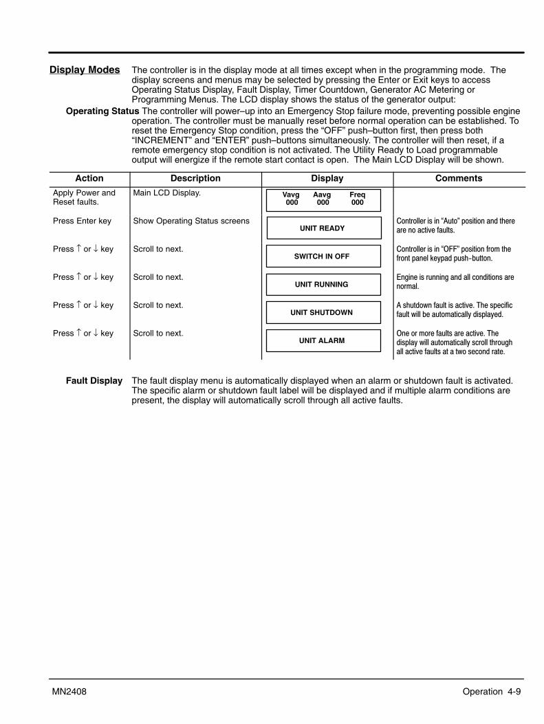
Operation 4-9MN2408
Display Modes The controller is in the display mode at all times except when in the programming mode. Thedisplay screens and menus may be selected by pressing the Enter or Exit keys to accessOperating Status Display, Fault Display, Timer Countdown, Generator AC Metering orProgramming Menus. The LCD display shows the status of the generator output:
Operating Status The controller will power�up into an Emergency Stop failure mode, preventing possible engineoperation. The controller must be manually reset before normal operation can be established. Toreset the Emergency Stop condition, press the �OFF� push�button first, then press both�INCREMENT� and �ENTER� push�buttons simultaneously. The controller will then reset, if aremote emergency stop condition is not activated. The Utility Ready to Load programmableoutput will energize if the remote start contact is open. The Main LCD Display will be shown.
Action Description Display Comments
Apply Power andReset faults.
Main LCD Display. Vavg 000
Aavg 000
Freq000
Press Enter key Show Operating Status screensUNIT READY
�����������-���@� ��1���-��������)�����������&��' ��-+
Press ↑ or ↓ key Scroll to next.SWITCH IN OFF
�����������-���@<��1���-����'��3��)�'����������!�(���� -)/� ����+
Press ↑ or ↓ key Scroll to next.UNIT RUNNING
��$���-�� ���$��������������-������3�+
Press ↑ or ↓ key Scroll to next.UNIT SHUTDOWN
��-) ���2��' ���-���&�+�4)��-���'�' ���2������ ��3����(��-��(��+
Press ↑ or ↓ key Scroll to next.UNIT ALARM
<������3����' ��-������&�+�4)��-��(�2��� ��3����(�-�������)�� $)�����&��' ��-�����2��-���������+
Fault Display The fault display menu is automatically displayed when an alarm or shutdown fault is activated.The specific alarm or shutdown fault label will be displayed and if multiple alarm conditions arepresent, the display will automatically scroll through all active faults.

4-10 Operation MN2408
Timer Countdown Timer countdown menus are automatically displayed when a specific time delay functionoccurs during a control sequence. When a time delay begins, the LCD display will show the timedelay function name (i.e. Engine Start Delay) and the current time remaining in the countdownsequence. When the timing function has expired, the LCD display will automatically change toeither the next timing sequence countdown display or return to the original system status menu.
Action Description Display Comments
Apply Power andReset faults.
Main LCD Display. Vavg 000
Aavg 000
Freq000
Show Operating Status screens ENGINE STARTDELAY 45 SEC
?-��(-�-���'���3�����(�' ������3�������3��$��3�+
Other time delay functions are:
ENGINE STARTDELAY 45 SEC
CRANK PERIOD XX SEC
REST PERIOD XX SEC
STARTER RE�ENGAGEDELAY XX SEC
BYPASSDELAY XX SEC
COOLDOWNDELAY XXXX SEC
WARMUPDELAY XX SEC
RETURNDELAY XX SEC
NEUTRALDELAY XX SEC
Note: Countdown screens only appear if Utility/Gen Ready To Load outputs are programmed.

Operation 4-11MN2408
Generator AC Metering The controller is in the display mode at all times except when in the programmingmode. The display screens and menus may be selected by pressing the Enter or Exit keys toaccess Operating Status Display, Fault Display, Timer Countdown, Generator AC Metering orProgramming Menus. The LCD display shows the status of the generator output:
Vavg 000
Aavg 000
Freq000
��!��������0������������&$���"
�&��$��%���$� ?-��(-��)��&��$��$��������&���$��-�'����2->�/�)-��-(-��3>��%�.�����"=��4<��"=��%<�4���//*)-�-�/�)-��-(-��3>��"=��4<��"=��%<�4���//*)-�-�������
�&��$��� ����� ?-��(-��)��&��$��$��������� ������-�'����2->�/�)-��-(-��3>��%�.�����"=����..�=4//*)-�-�� � ��/�)-��-(-��3>��%�.�����"=����..�=4//*)-�-�� �
���, ���( ?-��(-�$��������'��, ���(���)���;��AI�+�4)��'��, ���(�-��-��(���2�)����-�� �����'��6����'��)���;+
KVA632.23
��!�������./��&$���"
J%� ?-��(-��)��$�������B-��������2���� �� ����!��/&���3����-��J%��+��!�������#�����/��������&$���",�$!������$!�-
Vab600
Vbc600
Vca600
%� ?-��(-��)��$�������B-�� �� ��&���$�>�/�)-��-(-��3>��"=��4<��"=��%<�4���//*)-�-��������/�)-��-(-��3>��"=��4<��"=��%<�4���//*)-�-�������
%�� ?-��(-��)��$�������B-�� �� ��&���$�>�/�)-��-(-��3>��"=��4<��"=��%<�4���//*)-�-��������/�)-��-(-��3>��"=��4<�=��4.���%<�4���//*)-�-��/=
%� ?-��(-��)��$�������B-�� �� ��&���$�>�/�)-��-(-��3>��"=��4<��"=��%<�4���//*)-�-��������/�)-��-(-��3>��"=��4<�=��4.���%<�4���//*)-�-��/=
��!�������#����9��������/��������&$���",�$!������������-
Van347
Vbn347
Vcn347
=���> 4)��$�������B-��� ����3 -��������������������������������3���4��/%=�����)��@�� �������������1����3������)��3����$�3�3�� �3 -�����-��������-�@K�-1+
%� ?-��(-�$��������&���$��*)-�������=� ���+%�� ?-��(-�$��������&���$��*)-�������=� ���+%�� ?-��(-�$��������&���$��*)-�������=� ���+
��!�������#����� ����!���&$���" a408
b451
c415
Amps
�3�-� ?-��(-�$������������� ������-�'����2->�/�)-��-(-��3>�*A��������..�=4�/�)-��-(-��3>�*A��������..�=4
�3�-�� ?-��(-�$������������� ������-�'����2->�/�)-��-(-��3>�*A��������..�=4�/�)-��-(-��3>�*A��������..�=4
�3�-�� ?-��(-�$������������� ������-�'����2->�/�)-��-(-��3>�*A��������..�=4�/�)-��-(-��3>������������
��!����������1��!5"9:���2�����&$���" FREQHOURS
60.1 Hz56788 Hrs
�.�8 ?-��(-�$��������'��, ���(���)���;��AI�+�4)��'��, ���(�-��-��(���2�)����-�� �����'��6����'��)���;+A<�.� ?-��(-� ���������$�)� �-+

4-12 Operation MN2408
Engine Parameter Display Two engine operating parameter screens are provided.
+�����"�/������9�!�$!�����3,*�5��2����-
BATTERYSPEED
27.0 Vdc1800 rpm
�����( ?-��(-������(�&���$����?��&���-+�4)��&���$��-��-��(���2�)����-�� �����'��6����'��&���+����� ?-��(-���$���-���������&�� ���-�����3� ����.*#�+
�!�$!��*�2�������9�$��#������� ENG TEMPOIL PRESS
57 Deg C200 KPA
�=��4�#* ?-��(-���$�����3���� �������)�����$���-����- -�����)���)����-�-��������+<"��*.��� ?-��(-���$���������-- �������)����� ��-�����-, �����)��*�"�������J���-��-��J*����-�-��������+
Program Menus The programming menu is used to change values such as time delays, analog fault settings,digital fault settings. Access to the programming sub�menus may only be obtained with asecurity password number. The sub menus are organized as follows:
#�����2�%�!� PROGRAM MENU? NO
?-��(-��2��3�--$�-��)��3(������$$�������2����K������=<��(����--�$��)��"=�.�#�=4�� -)/� ����+�=<�*��$�33�$�- �/3�� -�����-�����2)���=<�-��-��(��+K���*��$�33�$�- �/3�� -�����������2)���K���-��-��(�������&����--2����� 3����-��������+
� PASSWORD 0
*��--�"=�.�#�=4����?��.�#�=4�����)�$���)���--2���+��*��--��=4�.�2)����)����������� 3����-��-��(��+'��3��!�"�%�3��-������&�2��)�����3����-�� ���������)�$���(�&� �-+�4)��'����(�-����$�'����)-���&���-��������+'��3�9�)�$���%�3��-������&�2����3��'(��(���3�����&� �+�4)��'����(�-����$�'����)-���&���-��2�����+%������'��3�9�)�$���%�3��-������&�2����3��'(��(���3�����&� �����&�263��'(��)��-�� ��(��--2������&���� 3���-+��������������'���3-�����--2����'���, ���+
The values of the parameter settings for your generator�set can be recorded for future referenceusing the Configuration Data Sheet shown in Figure 4-4.After the correct password number is entered, the you may choose one of four programmingmenus. Press INCREMENT or DECREMENT to find the desired menu then press ENTER.
MAIN MENU LOOP
ANALOG FAULT MENU LOOP
DIGITAL FAULT MENU LOOP
CALIBRATION MENU LOOP

Operation 4-13MN2408
Navigation HintsProgramming parameters are displayed in the same order as the Programming Sheets (seeFigures 4-5 to 4-8). To skip over parameters that do not require changes, push and hold theENTER push�button until the desired parameter is displayed. The EXIT push�button may beused to scroll backwards through the programming parameter loops.To change a parameter value, use the INCREMENT or DECREMENT push�buttons to scrollthrough the available options or to adjust a value as desired and press the ENTER to accept thenew value.Note: If programming mode is terminated before the last change is accepted (pressing ENTER),
that parameter value will remain unchanged.
Main Menu Loop The Main Menu Loop contains general system configuration programming such as system inputvoltages, currents, transformer ratios, as well as standard operating time delay functions.
�(-��3�%���$� ���������3���-(-��3�&���$��-������--������)-������)-��&���$���+�+���0H67���&����-(-��3�2� ��������������-7���+�4)�����$�33������$���'�&� �-�-����%/�� ���%+
�(-��3����, ���( ���������3���-(-��3�'��, ���(��'���)������AI����7��AI+�(-��3�*)-�- �������3��)��)����2����-��� ����-(-��3� -�������)��$��������-����+�+���)���-�$����)-��������)-��-(-��3�+=� ������������� �������K�-�'�$�������B-��� �������� �����-����������������������������3���4��/%=������-���-��������-��(
���/�� �������&���$�-�'�������)-� �0�2���-(-��3+%���$�����-�$�.�� ����������&���$��-��-�$�2��$����������-�'��3���:����7���&���- ����������+�+�������'��>��+�5)����������
���-'��3��-���� ��;���'���&���$��-��-�$ ��������)����� ��������-'��3���������+$+�2)��� -�$�7��>������-'��3��- ��������� 3�����'���+
� ���������-�$�.�� ����� ������-��-�$�2��$����������-�'��3�� ���������-'��3��-���4B-� ��������)����� ������4�������+$+�2)��� -�$�7��>���4 ��������� 3�����'�����+
4�3���� ������� ��������)����-���� ��-�'�����$�����3���� ����-��(�������$�-������->�?�$���-��)���)������?�$���-����- -+�=���>����3�-������-�������� ��3����(���/���'$ ���2)����)�$�$����2�����)���)��������$���-����- -+
*��-- ������� ��������)����-���� ��-�'�����$������-- ����-��(�������$�-������->�*� ��-�����-, �����)��*�"�����J���-��-�J*��+���=���>����3�-������-�������� ��3����(���/���'$ ���2)����)�$�$����2����*�"����J*�+
�����?��( ���������-������$���-�������(��3����-�����-+�"'���$���-�������(�-�������, ��� �-������;���+���=���>�"'����)������������ ���' �����-���� -�� ��)����$���-�������(��3��-)� ������-���-���, ����'����)�-��' �����-+
���!�43� ���������-�������!�$��3����-�����-+�"'��(�������!�$�-�-������� ��)-��3��2�������)�����!��3���������3��+.�-��43� ���������-������-���3�����2�������!�$����3��-+��<��(�&���'�3 ���������!����3��-����-��������+�
=���>�4)-�&� ��2������$������'����(��������3���)-���������$�33��+�������.�/��$$��? ������4)-�'�� ����)��!-�'����-�����-$���� ��$����!�$+�"'����-�����-$���-�-��-�� ��)�������������-- 3�-��)���)�
��$���-������-������ ���$��)����$����&�������-��$$�-���'�����)�����$�33����3�����( ������/��$$�-��$�+�4)-������--�2��������� �����-�����-$���-�-��-���������!�$��3�������- �2)�)�&������ �-�'�-�+�"'��-�����-$���-�-��-�� ����!�$������ �-� �����)����$���-���-�������&�����!������������ �-+������3����-�����-�-���-�����+�+��-����$��'���-�����-�2������3������!�$�'�����-�����-�'����2)�)��3��'����-����-$���-��������� ��)�����!�� �� ��2��������3�&���'�������-�����-���������(���'������/��$$�$+��=���>�4)-������-�3�����)����(�������!�$�' ���������-�������������'��)��� 3�����'����3��-�-�������+4)���'��� ��)��@���!1��3��-)� ���������-�����+�4���-�����)-�'�� �� �-������;���+
= 3����<'����!��(���- ��������)��� 3�����'����!�$��(���-���, ���+��I����2�����' ���������+��(�--�?��( 4)-�-����$�-��)���3���������)�����3�����) ���2��' ��-�2������$������'�������!��-������� ����2�$��)����$�����
-�����������-����3��������$�3�����+�+��������������-- �� ����+�+�4(����(����-�����-+�������2��43� ���������-�����������2���3����-�����-+�������9999�-�����-��'��������2���3��3(�������$�33��+��������;����'����
��, ���+�=���>�"'��)�������������-� -��������#������������-�����33���������-����)���������2���3�������3�3 3��'���-�����-�������2��)��$��������������-'���<''�������'���������$��)���������2���3�+����- ��-��)������-����-'������''��'�$����������������-�����$��)����$��+�
=�3�����$���.*# ��������)����3�����$���-���������&�� ���-�����3� ����.*#�+��(2)����4���) ��������)��� 3�����'���$�$�������)�����)����$���'�(2)���+�4)��3$�������!/ ��3 -������-���������-��-���)��-3�
����)�'���-�����-��-�$�-����$�33��+���!�?-������������� �������!��-��������-��������������$���'���3���-���� �+�+���F�����0��.*#�������:���.*#���$��+<&��-���� �����&��-�����-) ���2����������������$���'���3���-������+�+����F�����9:��.*#�������:���.*#���$���+<&��-�����4��-����?��(�����������-�����&��-��������-�������(��3����-�����-+�43��-����$�3(������������������)-��'�-�����-+. ��< �� ����/-'� 5)�����������'����(�-����$� ��)-�'�� ����)��-��)��� ��� �� �� �����)�����������������&�-��-�����-��-�$�-$��+
4)-����&���-���--�����3$��� -����(�-����$��)����$���2�)����-�����-��-�$�'������!��-�����������&��-����+�"'�-������� ���- ����)���)��-�����-$���-�������--��)���+�%���'��3��)��3$�������!� ��2)����)����$��-����!�$+�=���>�"'��)-�'�� ���-��-���� �����&��-���������������������!��-��������2���������&����'��)��-�����-$���'�-+�"'(� ��-�����)-�'�� ���������-����$�(�����33���-��)����! �����!��-�����������������������������&��-��������������-����&���+

4-14 Operation MN2408
Main Menu Loop Continued��--�<'��������$�� ��������)����-����������+�+���3����-) ���2���2)������--��'�-�����-$���-����������� ��$��������+�
=���>�����--��'�-�����-$���3 -��������������'������$����)����-�����-����������)����-��������+��33����������@=���"��� ��1�� ��������������-�'����33���'����3���������-���������&����� ��$�3� ���������+A��������=���"��� �� 4)��A����3(�������$�33������-� ���2)����)������������-�������$�3����-�-2��)���'��3��)��� �����-���+�"'��)�
A����-��������-� �� �-���������$�3�-����$�=�+5�3/ ��?��( 4)��5�.#/�*�?��(�3�� �����-�2)����)������.��(�4���������$�33����� �� ��-�-����������(����(�'����#�
��������+���������)����-�����3����-�����- �2)�)��)��$����������, ��-�����''���&��(�@2�3/ �1���'����������$���+�4)-�-��(����(�-���'�����-�����-+�4)��5�3/���?��(�-�������'�����)��$��������-���&�����$�33���&���$����'��, ���(��3�-�������)�����$����$�33�$�3�� -�+
=� ����?��( 4)��=� ����?��(�3�� �����-�2)����)������(�.��(�4���������$�33����� �� ��-�-����������(����(�'����#���������+�4)��=� ����?��(��3���-� -���2)������-'����$����2�����)��&�������2���-� ���-+�5)������-'����$'��3��)�� ���(�- ���(�����)��$��������- ���( ��)��=� ����?��(��3���2���-����2)����)������(�.��(�4������� �� ���/����$;�-+�5)����)��=� ����?��(��3�������������- ��)�����������.��(�4������� �� ��-�����$;��+��4)�� ���-���'��)��=� ����?��(��3���-�������&����� ���'��)-�����-'��- �2)�)�3(����� -����(��'-�����-'�������)��2��-� ���-��'�- ���(����� ���'�-(��)���-3+�4)��=� ����?��(��3�����- ��-��)������&���$�-����(���'�����)����-'���-������+���������)����-�����3����-�����-+�4)��=� ����?��(��3���-��(����(�-����'�����-�����-+
=���> 4)��=� ����?��(�'�� ���-����(��''���&��2)��������������(�)����@��������/�(��1����-'���-2��)�-����������+��������������'���' ��)������������'��3������� -��2�)���)����(��-��'����-'���-2��)�3��)�-3-+
.�� ���?��( 4)��.�� ���?��(�3�� �����-�2)����)������(�.��(�4������� �� ��-�-����������(����(�'����#����������+�4)�.�� ���?��(�-�������2)����)����3����-����-$���-���3�&����-$���$�� ���(���2���-�&�����+��'�����)��.�� ��?��(��3��������- ��)�����������.��(�4������� �� ��-���3�&�� �����)������(�.��(�4������� �� ������$;�-���-$������-'����)��������!�����)�� ���(�- ���(+�4)��� ���-���'��)��.�� ���?��(��3���-������- ����)���)�� ���(���2��)-���� ���������-���(�-����'����)��-���������3����������'�����)������-����-'��������!�����)�� ���(�- ���(+�4)�.�� ���?��(��3���-��(����(�-���'�������-�����-+
Caution: The Programmable Output Contacts selection must agree with the external control wiringprior to energizing the controller. Failure to do so may cause severe equipment damage.
*��$�33����< �� ��������-����������)����-����' �������)��2�����&����)�����$�33�������(�� �� ��������+�<����'��)��'����2�$�' �����-�3(����-�������>����$;��4������� ����.��(�4����� ���������-�� ���(�$���� ����(�.��(�4�����<���(�--�43�����3������ ��33������ ?$���� ��-�D����0 �2��)�=���"��� ��<&��-���� ��$���.��(� ��--�<'��������$�� ��$���. ���� �����2����%���$� *��)���A$)����%���$� ��$���. ���$� 5�!����%���$��4��4�-�� ��2�<��*��--�D�����3 ��33������3� ��33����) ���2����2�<��*��--�D���) ���2� A$)���$�4�3��D�����3 A$)���$�4�3��D���) ���2�
.�-���. ��A� �- 4)��)� �3�����3(������-������;����)� �-�2)���(�-�-����$�33��+�=���>�4)-����$�33�$����3���-����(����--����2)��� -�$��)��@#-���1����$�33�$�-�� ��(��--2���+
Analog Fault Menu Loop The controller�s analog fault settings are described as follows:��&�� ���-��)���� �����$�-$���-���������2)�)��)��-��������' ����(���2��������&���+�
=���>��������&���$��' ������ �- ��2����&��-��+�+���!/ ��G�����/� ���3 -��������$�33��+����� ����2-��' �����������)��������3�' ��������) ���2��' ��+���3����) "'���' ���2-�-���-������3 ���3(����-��������-��@���)�$1���3����@=��/���)�$1���3+�������)�$���3�-����
������� �������-�����33�������-��+�=���>�4)-�&� �����(�����-�'���3�' ��-�������$�33��+��) ���2��' ��-���� ��3����(�-���-����)�$+
�(�--�<�������?��( ����2-��)����3����-) ���2��' ����������-����� ����'�����)���(�--��3���)-�������+�� ��-��)������������(������������������3�-��+�+���$���� ���$����-�������+
4��-����?��(�43�- ����2-��)��-��������' ����������-����� �����)�����(�������)-�������+��?��(��3�-�����+�����999+9�-�����-+

Operation 4-15MN2408
Digital Fault Menu Loop The controller�s digital fault settings are described as follows:Caution: The Digital Fault Label selection must agree with the external control wiring prior to
energizing the controller. Failure to do so may cause severe equipment damage.?$���� ������� ��������)����-����' ������� ��)�-�����-�����������/&������3�3��(+
���?3����4������ A$)�<��4�3� ����)�$���"�� ����� A$)�5���$�4�3�����)�$�4�� ���� ��2����������&�� ���!���4������ ��2���$���4�3�?����� ��2�� �����&�� �����4���(��� ��2�� ���*��--�������!���<���� ��2�<����&�� ��� ���� ��� ��2�<��*��-- ��A$)�����$�4�3�� .�3�����3��$+-��� A$)��������%������ .�&��-��*�2��A$)���$���4�3�� �-��. �� �� A$)���$���%������ �4��"���(�--A$)�� �����&��� � �����! A$)�<����&��� ��2�� ���*��--=������4�-�� ����)�$����� CA$)��!3�'��3� %����?3������A$)�� �����&�� ���4���(�� @���!1��+�+���������'��� � -����� �-�
����� ����2-��' �����������)��������3�' ��������) ���2��' ��+=���>���(���&������3����-) ���2��' ���2�������$;���)��@��33���'�1�' ������-� ����)����3�)���+
���3����) "'���' ���2-�-���-������3 ���3(����-��������-��@���)�$1���3����@=��/���)�$1���3+�������)�$���3�-����������� �������-�����33�������-��+�=���>�4)-�&� �����(�����-�'���3�' ��-�������$�33��+��) ���2��' ��-���� ��3����(�-���-����)�$+
*����( ����2-��)���$���' ������ ��������-���'���<����������������-��������-��-�$�������-+�(�--�<�������?��( ����2-��)����3����-) ���2��' ����������-����� ����'�����)���(�--��3���)-�������+�� ��-��)������������(�����
�������������3�-��+�+���$���� ���$����-�������+4��-����?��(�43�- ����2-��)��-��������' ����������-����� �����)�����(�������)-�������+��?��(��3�-�����+�����999+9�-�����-+"������������?$���"�� ��*��$�33�$���5)�����$����� ��-�-������"����' ����� ��)�-��-����$-�3 -��������$�33��������- ������������������>
������ ���3���3����)� =�*����(� ���-��(�--�<������� =�4��-����43�� �+�
=���> 4)�������-�����$��$���� �� ��3 -���-��������$�33���'���"?���������������������������+=������4�-����������?$���"�� ��*��$�33�$����
4)��=������4�-���$����� ��'�� ���-��(����(� -��������#����������2)������-���, ������������ ��3���3���=������4�-���'��)����$��6$��������-��+����������'��3����������������-������!��3���-���, �����������������������)���$����� ����� ��2)�)�-����$�33���'���@=������4�-�1+���5)�����$����� ��-����$�33���-�=�����4�-� ��)�-��-����$-�3 -��������$�33��������- ������������������>������ ���3���3����)� =�*����(� ���-��<��<����������������������������� �� -����(�--�<������� =�4��-����43�� �+�
Calibration Menu Loop AC Voltage, AC current and battery voltage analog circuits are factory calibrated and shouldnot require field calibration. If field calibration is required, refer to the calibration procedure.
Voltage Sensing Calibration (Phase To Phase or Phase To Neutral)� VOLTS AB ZERO
99 600V
?-��(-��)��$���������)-��&���$�-��������������+?-��(-��)���(����'���������' ����� ���)���I�.<�����*�=+�?-��(-��)��������������������'������ 3������/����� -������������)����������&���$������$+�=���>�4����������(���������(��'��)��&���$��-��-��- ��)��I�.<�' ������3 -���������������'�����)���*�=�' �����+?-��(-��)���� ��&���$��3�- ��3�����)��2�������)��-3��&� ��-�-)�2������)��#������-��(�3�� -�'��$��������- ���(+�4)-�&���$������$�3(������������)$)��������2����(��)�$�$��)������������'������ 3���+
Voltage Calibration Procedure=���> I������������3 -�������3���������'���������������+
;���� ��$����$�! ���������������������&���3������'���, ���&���$����$������� ��(�����)��#�������������������3��-�--�����2�)��)��&���$���)-�-��������������+�5�)��)��$��������-������ ����'�3��)����-�I����&���-�����)���)-�-�������������+���"���)�����$�33�$�3��� �-�����������)��'��)����-����$��������- ���(�&���$���)-�-��+�+��)-������)-�����)-������� �����2�)��)��I�.<�' ������-�������+��-���)��"=�.�#�=4����?��.�#�=4�� -)/� ����-�����E -���)�����������'������ 3������������;����&���-�����)���$)��)���-����'��)���-��(�-����'�3���2�)��)���������&���3����+�4)��'����(���' �������������'�����-���H+�"����-�$��)-�2����-���)���-��(���&� � ����&��-��(�����-�$��)-�&� ��2��������-���)���-��(���&� �+�=���>���E -��$��)��I�.<�' ������2�)�&���$��������2�����- �������/�����&���$������$-+�5�)��)����������&���$���-��(�� ����--��)���=4�.�� -)/� ���������������)������������'������ 3���+�.�������)�����������'������ 3��������)�����$�33�$�-)����'���' � �����'������+�.������)-������� ���'��������3��$��)-�-+
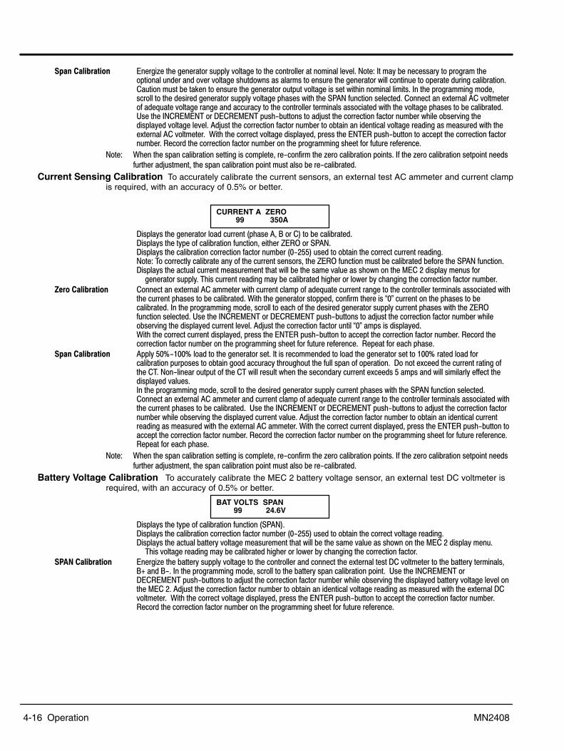
4-16 Operation MN2408
��!� ��$����$�! ����$;���)��$��������- ���(�&���$������)�����������������3�����&��+�=���>�"��3(��������--�(�������$�3��)�������� ���������&���&���$��-) ���2�-�-���3-������- ����)��$��������2�������� ������������� ��$��������+� ����3 -������!��������- ����)��$��������� �� ��&���$��-�-���2�)����3����3�-+�"���)�����$�33�$�3��� -����������)����-����$��������- ���(�&���$���)-�-�2�)��)���*�=�' ������-�������+����������������������&���3�����'���, ���&���$����$������� ��(�����)����������������3��-�--������2�)��)��&���$���)-�-��������������+���-���)��"=�.�#�=4����?��.�#�=4�� -)/� ����-�����E -���)������������'������ 3����2)�����-��&�$��)��-��(���&���$����&��+���E -���)������������'������ 3���������������������&���$������$�-�3�- ����2�)��)������������&���3����+��5�)��)����������&���$���-��(�� ����--��)���=4�.�� -)/� ���������������)������������'����� 3���+�.�������)������������'������ 3��������)�����$�33�$�-)����'���' � �����'������+
=���> 5)����)��-�����������-����$�-���3����� ���/���'�3��)��;����������������-+�"'��)��;������������-�����������-' ��)����E -�3��� ��)��-����������������3 -���-�������/�������+
Current Sensing Calibration To accurately calibrate the current sensors, an external test AC ammeter and current clampis required, with an accuracy of 0.5% or better.
�
� CURRENT A ZERO 99 350A
?-��(-��)��$������������� ��������)-��� ����������������������+?-��(-��)���(����'���������' ����� ���)���I�.<�����*�=+?-��(-��)��������������������'������ 3������/����� -������������)����������� ����������$+�=���>�4����������(���������(��'��)��� ������-��-��- ��)��I�.<�' ������3 -���������������'�����)���*�=�' �����+?-��(-��)���� ��� ������3�- ��3�����)��2�������)��-3��&� ��-�-)�2������)��#������-��(�3�� -�'���
$��������- ���(+�4)-�� ����������$�3(������������)$)��������2����(��)�$�$��)������������'������ 3���+;���� ��$����$�! ���������������������33�����2�)�� ��������3���'���, ���� ��������$������)����������������3��-�--������2�)
�)��� �������)-�-��������������+�5�)��)��$��������-������ ����'�3��)����-�@�1�� ����������)���)-�-�������������+�"���)�����$�33�$�3��� �-�����������)��'��)����-����$��������- ���(�� �������)-�-�2�)��)��I�.<' ������-�������+��-���)��"=�.�#�=4����?��.�#�=4�� -)/� ����-�����E -���)������������'������ 3����2)����-��&�$��)���-��(���� ��������&��+���E -���)������������'����� ����@�1�3�-�-��-��(��+5�)��)����������� �������-��(�� ����--��)���=4�.�� -)/� ���������������)������������'������ 3���+�.�������)�����������'������ 3��������)�����$�33�$�-)����'���' � �����'������+��.�����'�����)��)-�+
��!� ��$����$�! ����(���F/���F���������)��$��������-��+�"��-�����33��������������)��$��������-���������F����������'����������� ���-�-���������$������ ��(��)�� $)� ���)��' ���-����'��������+��?��������������)��� ���������$��'�)���4+�=��/������ �� ���'��)���4�2�����- ���2)����)��-������(�� ������������-���3�-����2���-3���(��''�����)��-��(���&� �-+��"���)�����$�33�$�3��� �-����������)����-����$��������- ���(�� �������)-�-�2�)��)���*�=�' ������-�������+���������������������33��������� ��������3���'���, ���� ��������$������)����������������3��-�--������2�)�)��� �������)-�-��������������+���-���)��"=�.�#�=4����?��.�#�=4�� -)/� ����-�����E -���)������������'����� 3����2)�����-��&�$��)���-��(���� ������&� �+���E -���)������������'������ 3���������������������� ���������$�-�3�- ����2�)��)�������������33����+�5�)��)����������� �������-��(�� ����--��)���=4�.�� -)/� ��������������)������������'������ 3���+�.�������)������������'������ 3��������)�����$�33�$�-)����'���' � �����'������+.�����'�����)��)-�+
=���> 5)����)��-�����������-����$�-���3����� ���/���'�3��)��;����������������-+�"'��)��;������������-�����������-' ��)����E -�3��� ��)��-����������������3 -���-�������/�������+
Battery Voltage Calibration To accurately calibrate the MEC 2 battery voltage sensor, an external test DC voltmeter isrequired, with an accuracy of 0.5% or better.
� BAT VOLTS SPAN 99 24.6V
?-��(-��)���(����'���������' ��������*�=�+?-��(-��)��������������������'������ 3������/����� -������������)����������&���$������$+?-��(-��)���� �������(�&���$��3�- ��3�����)��2�������)��-3��&� ��-�-)�2������)��#������-��(�3�� +�
4)-�&���$������$�3(������������)$)��������2����(��)�$�$��)������������'����+�#��� ��$����$�!� ����$;���)�������(�- ���(�&���$������)�������������������������)������������-��?��&���3���������)�������(����3��-
�L�����/+�"���)�����$�33�$�3��� �-����������)�������(�-���������������+���-���)��"=�.�#�=4���?��.�#�=4�� -)/� ����-�����E -���)������������'������ 3����2)�����-��&�$��)���-��(��������(�&���$����&������)��#����+���E -���)������������'������ 3���������������������&���$������$�-�3�- ����2�)��)����������?�&���3����+��5�)��)����������&���$���-��(�� ����--��)���=4�.�� -)/� ���������������)������������'������ 3���+.�������)������������'������ 3��������)�����$�33�$�-)����'���' � �����'������+

Operation 4-17MN2408
Engine Temperature & Oil Pressure CalibrationTo accurately calibrate the controller�s temperature sensor, an external temporary engine mountedtemperature gauge is required. The external temperature gauge should be connected as close as possibleto the temperature sender. To accurately calibrate the controller�s pressure sensor, an external temporary engine mounted pressuregauge is required. The external pressure gauge should be connected as close as possible to the pressuresender.
� ENGINE TEMP 127 95�C
?-��(-��)���(����'���������' �����+?-��(-��)��������������������'������ 3������/����� -������������)����������4�3���� ������*��-- �������$+?-��(-��)���� ����3���� ���������-- ���3�- ��3����-)�2������)���-��(�3�� -+4)-�����$�3(������������)$)��������2����(��)�$�$��)������������'������ 3���+
�!�$!��*�2������� 4)����$�����3���� ������$���� ��3 -�������������2�)��)����$�����3���� ���-������3� ���������)����$��+�����������3����(���$���3� �������3���� ���$ $���'�- ������� ��(����-�����)����$��+��'�����)����$�����)�-����3��������$���3���� �� ��������)�����$�33�$�3�������-����������)��@��$���4�3���� ���<''-��1������������+��-���)��"=�.�#�=4����?��.�#�=4�� -)/� ����-�����E -���)������������'������ 3����2)����-��&�$��)���-��(�����3���� ��+���E -���)������������'������ 3�������������)�����������3���� �������$�-3�- ����2�)��)������������3���� ���$ $�+�5�)��)������������3���� ����-��(�� ����--��)��@�����1�� -)/� ��������������)������������'������ 3���+�.�������)������������'���������)�����$�33�$�-)����'���' � �����'������+
�$��#������� �����������3����(���$���3� ��������-- ���$ $���'�- ������� ��(����-�����)����$��+��'�����)����$�����)�-����3��������$����-- ��������3���� �� ��������)�����$�33�$�3�������-����������)��@��$���*��-- ��<''-��1�������������+��-���)��"=�.�#�=4����?��.�#�=4�� -)/� ����-�����E -���)������������'������ 3���2)�����-��&�$��)���-��(������-- ��+���E -���)������������'������ 3�������������)������������-- �������$�-3�- ����2�)��)�������������-- ���$ $�+��5�)��)�������������-- ����-��(�� ����--��)��@�����@�� -)/� ��������������)������������'����+�.�������)������������'���������)�����$�33�$�-)����'���' � �����'������+
�!�$!��*�2�������
��!3���'��$���!5�
�$�#�������
��!3���'��$���!5�
�� � ��2� .#� #�( ��2�
�9� ��� �� ���0 ��� �:�H0 �9� �0 97� �0� 0���7 �:� �: :97 ��� 0:��: �H� �� :�H ��� �0��� �7� �9 H�: ��� 7���� ��� 07 7:9 ��� H��:0 �0� �� 7�� 9� H9�77 ��� 7� ��� :� :9�0: ��� H7 0:� H� ������ ��� 9� 0�0 7� ��0��� ��� ��7 �0� �� ��H�90 9� �0H �H7 0� �0��H7 :� �9H ��H �� �7���� H� �9� ��: �� �:��0� 7� 0�7 79 �� ��7��� �� 7����0 0� 9��:7 �� �0:77: �� ������ �� �700�� � 7�:0
=���> ���������--��������-)�2�����'���<��*��-- �����������6�/���7�0��4)�3�-����6�� �#� '�� ���/�?���� ��6������H+�?������������3 -����� -���2�)�#���-�'�2���&��-����+:�����$����������&� -�-�'�2���&��-��-��������� -���+
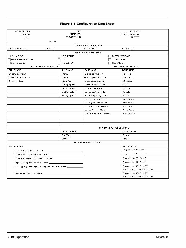
4-18 Operation MN2408
Figure 4-4 Configuration Data Sheet
�
�
�
�
�
�
�
�
�

Operation 4-19MN2408
Figure 4-5 Main Menu Loop ParametersParameter Setting Range
System Voltage (Line To Line) XXXXX VAC 120�15000VACSystem Frequency 50Hz/60Hz Toggle Between 50/60 HzSystem Phases 1 Phase/3 Phase Toggle Between 1 & 3 Phasey
Neutral Connected Toggle Between Yes/NoVoltage Sensing Voltage Sensing Pt RatioRatio XXX Enter Number 1�208 (1=Direct)Current Sensing Current Sensing Ct RatioRatio XXX Enter Number 1�999 (1=Direct)
Temperature Scale Deg C/Deg F Toggle Between Deg C/Deg FPressure Scale PSI/KPA Toggle Between Psi/KpaStart Delay XXX Seconds 0�999 SecondsCrank Time XX Seconds 0�99 SecondsRest Time XX Seconds 0�99 SecondsStarter Re�engage Delay XX Seconds 0�99 Seconds 0=DisabledNumber Of Cranks XX Cranks 0�99 Times 0=ContinuousBypass Delay XX Seconds 0�99 SecondsCool down Delay XX Seconds 0�9999 SecondsNominal RPM XXXX RPM 0�4000RPMFlywheel Teeth (Engine Speed Sensing, Magnetic Pick Up
XXX Teeth 0�999 Teeth
Crank Disconnect XX % 0�100%Overspeed XX % 100�150%Overspeed Transient X.X Seconds 0.0�9.9 SecondsRun Output Fail Safe Yes/No Toggle Between Yes/NoLoss Of Speed Signal Shutdown Alarm/Shutdown Toggle Between Alarm/ShutdownCommon Fail For Not In Auto Yes/No Toggle Between Yes/NoHorn For Not In Auto Toggle Between Yes/NoProg Output #1 Common Fail (Factory setting)Prog Output #2 Common Fail (Factory setting)Prog Output #3 Common Fail (Factory setting)Prog Output #4 Common Fail (Factory setting)Prog Output #5 Common Fail (Factory setting)Prog Output #6 Common Fail (Factory setting)Warm�up Delay 0�99 SecondsNeutral Delay 0�99 SecondsReturn Delay 0�999 SecondsReset Run Hours Access by Master Password OnlyYes/No Toggle Between Yes/No
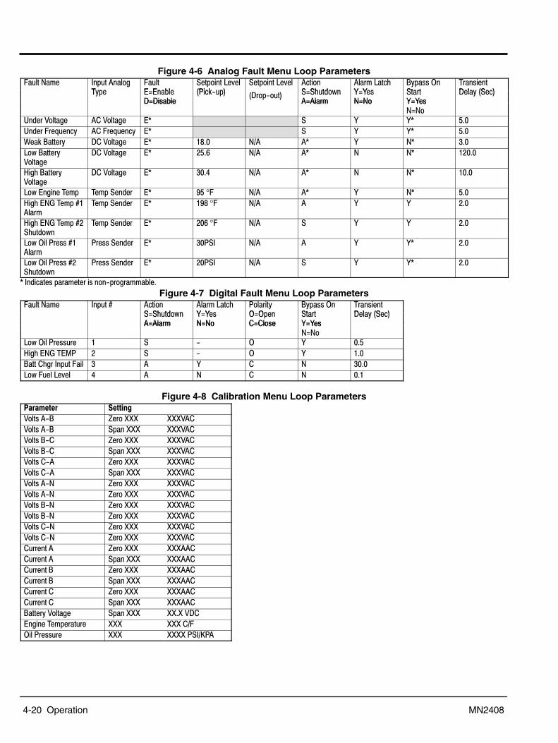
4-20 Operation MN2408
Figure 4-6 Analog Fault Menu Loop Parameters� ���=3� "�� ������$
4(��� ��� �����
����������&���*�! ��
����������&�� ������ �) ���2�
���3����)K K�-
�(�--�<�����
4��-���?��( �����4(�� �M�����
?M?-����*�!/ �� �?���/� �� �M�) ���2�
�M���3KMK�-=M=�
����KMK�-
?��(������?M?-��� �M���3 =M=� KMK�-
=M=�������%���$� ���%���$� �C � K KC �+����������, ���( ������, ���( �C � K KC �+�5�!������( ?��%���$� �C �:+� =6� �C K =C �+���2������(%���$�
?��%���$� �C ��+7 =6� �C = =C ���+�
A$)������(%���$�
?��%���$� �C ��+0 =6� �C = =C ��+�
��2���$���4�3� 4�3�������� �C 9��°� =6� �C K =C �+�A$)��=��4�3��D����3
4�3�������� �C �9:�°� =6� � K K �+�
A$)��=��4�3��D��) ���2�
4�3�������� �C ��7�°� =6� � K K �+�
��2�<��*��--�D����3
*��--������� �C ��*�" =6� � K KC �+�
��2�<��*��--�D��) ���2�
*��--������� �C ��*�" =6� � K KC �+�
C�"�����-���3�����-����/���$�33���+Figure 4-7 Digital Fault Menu Loop Parameters
� ���=3� "�� ��D ������ �) ���2�
���3����)K K�-
*����(< <���
�(�--�<�����
4��-���?��( ������M�) ���2�
�M���3KMK�-=M=�
<M<����M���-�
����KMK�-
?��(�������M���3 =M=� �M���-� KMK�-
=M=���2�<��*��-- �� � � / < K �+�A$)��=��4�#* � � / < K �+������)$��"�� ���� � � K � = ��+���2�� �����&�� 0 � = � = �+�
Figure 4-8 Calibration Menu Loop Parameters#���2���� ����$!�
%���-��/� I����NNN NNN%��%���-��/� ����NNN NNN%��%���-��/� I����NNN NNN%��%���-��/� ����NNN NNN%��%���-��/� I����NNN NNN%��%���-��/� ����NNN NNN%��%���-��/= I����NNN NNN%��%���-��/= I����NNN NNN%��%���-��/= I����NNN NNN%��%���-��/= I����NNN NNN%��%���-��/= I����NNN NNN%��%���-��/= I����NNN NNN%��� ������� I����NNN NNN���� ������� ����NNN NNN���� ������� I����NNN NNN���� ������� ����NNN NNN���� ������� I����NNN NNN���� ������� ����NNN NNN��������(�%���$� ����NNN NN+N�%?���$���4�3���� �� NNN NNN��6�<��*��-- �� NNN NNNN�*�"6J*�

Operation 4-21MN2408
Figure 4-9 Engine Control Connections
1
2
3
4
5
6
7
8
9
10
11
12
17
16
15
14
13
38
37GRD
CR
MP2MP1
19
18
24
23
B �
B ++�
CRANK
RUN
25
26
27
28
29
30
31
32
33
34
2435
36
22
21
20
PROGRAMMABLECONTACT #4
PROGRAMMABLECONTACT #3
PROGRAMMABLECONTACT #2
PROGRAMMABLECONTACT #1
COMMON FAIL CONTACT(OPERATES ON AN ALARM ORSHUTDOWN CONDITION)
IN
IC
IB
IA
VN
VC
VB
VA
VC
VB
VA
1A
1A
1A
N
GRD
GENERATOR OUTPUTCURRENT SENSINGTRANSFORMERS5 Aac SECONDARY(DELETE PHASE CFOR SINGLE PHASESYSTEMS)
10A GENERATOROUTPUT VOLTAGE
(DELETE PHASE VCFOR SINGLE PHASESYSTEMS)
MEC 20
RUN CIRCUIT(FUEL SOL., GOV.)
GRD
DIGITAL FAULT INPUTCONTACTS
(MEC 2 = 1�4MEC20 = 1�12)
REMOTE START CONTACT
REMOTE FAULT RESET(CLOSE TO RESET)
REMOTE EMERGENCY STOP(CLOSE TO STOP)
ENGINE TEMPERATURE SENDER
OIL PRESSURE SENDER
SPEED SENSINGMAGNETIC PICKUP
RUN CIRCUIT
CRANK PILOT RELAY
φA
φB
φC
12VDC (24VDC)STARTING BATTERY
(25, 26, 27 Not used in MEC 2)
(Not used in MEC 2)

4-22 Operation MN2408
Operator Control Panel (Analog Engine Controller Only)Figure 4-10 Analog Operator Control Panel
� +
OFF
1
2
3
#�!����$�����-2��)��<�/<''��4 ��-�����2���3�-������ 3�����)��������������+#�!����$���������� -��'���������$)�-+%������ �!�����-2��)��#� ��. �/�����/�� ��������#� ��. ��/�����-��)����$���3� ��(+�����/�����-��)����$������$�������+� ��������/�����-��)����$���2)����)��@.�3����-���1����3��-����
���-��+&$���"���2�A$)�4�3���� ���/�"�����-�����--&����$������������3���� ��+��2�<��*��-- ���/�"�����-���2���$���������-- ��+<&��-�����/�"�����-���$���-�����-�$�������)�����-����3�+<&�����!�/��� ����'��)����$������-�����(��)�������'��)�����!������
���������- ��-�����@�&�����!1�-) ���2�������3�������+/��������36������"����-�� ��� ?����-�� �)�� ��������� � �� �� &���$�� ��-��(��� ��%<�4����3�����
� �/�������3��������$��-��(��'�$��������� �� ��&���$����.#��&���-+�%%�*�'��-2��)������-����<''�/�=��� ������-�3�- �����(��)���3���$��3����+��/�*)-����� ������-�3�- �����(��)���3���$��3����+��/�*)-����� ������-�3�- �����(��)���3���$��3����+��/�*)-����� ������-�3�- �����(��)���3���$��3����+�2������3��������$��-��(��'�$��������� �� ��� ��������.#��3�-+:���<�3��������$��-��(��'�$��������� �� ��'��, ���(���A���;++�����"�/�������3����?-��(-��)��&���$���'��)����$���-����$������(+�!�$!��*�2��������3����?-��(-��)����3���� ����'��)����$���������+�$��#��������3����?-��(-���$���������-- ��+'�!�*$2��,:����-��3����4�������-����3����������'�$��������-����������+
PANEL LIGHTS
ON OFF
MASTER CONTROL
MANUALRUN
AUTOSTART
STOP
OVERSPEEDOVERCRANK
HIGH TEMPERATURELOW OIL PRESSURE
VOLTAGE AMPERAGE
AMMETER
HERTZ
PANEL LIGHTFUSE
VOLTAGEADJUST
Oil PressureBattery Volts
Engine Temp
RUN TIME (HOURS)
Panel LightPanel Light
Operating Procedures The engine�generator controller is designed to start and stop an engine from either a local(�Manual�) or remote (�Automatic�) mode. When a start command is issued, the controller issuesa run and crank output signal. The controller then monitors engine speed and when crankdisconnect speed is reached, the crank signal is terminated. While the engine accelerates tonormal speed, the controller continuously monitors the engines speed signal. Should the enginespeed exceed the maximum predetermined setpoint, the overspeed shutdown fault circuit willactivate, terminating the run signal.In addition to overspeed shutdown, the engine controller also monitors many other engineprotection circuits and should they be activated, the engine will be stopped and/or alarm initiated.The engine will automatically stop for any shutdown condition, or when the remote and/or localstart signal is removed. The engine controller operation includes time delay circuits for normaloperating conditions such as start delays, cool down and cranking periods.

Operation 4-23MN2408
Manual Start/Stop To manually Start the Gen�Set, set the Master Control switch to the �Manual Run� position. Thefollowing happens:
1. When the �Manual Run� push�button is pressed, an Engine Start Delay timer isinitiated. (The start sequence will not be initiated if any shutdown fault condition ispresent.)
2. When the engine start delay time expires, an engine RUN and CRANK output signalwill be initiated. (The RUN output may be programmed to only energize when a startsignal is initiated and an engine speed signal is detected.)
3. When the engine starts and begins to accelerate to nominal speed, the controllersspeed sensor will terminate the CRANK output when engine speed reachesapproximately 20% speed (i.e. CRANK DISCONNECT speed setpoint).
To manually Stop the Gen�Set, set the Master Control switch to the �Stop� position. Thecontrollers RUN output will be immediately terminated which will initiate the engine stopsequence. The engine is locked out and will not run with the Master Control switch in �Stop�.
Automatic Start/Stop To setup the generator for automatic operation, set the Master Control switch to the �Auto Start�position. The following happens:
1. The engine will automatically start upon activation of the remote start contact input. Theremote device initiates a start sequence upon contact closure.
2. When the remote start signal is activated, the engine will start as per the sequence ofoperation described for the manual start sequence.
3. The automatic stop sequence will be initiated by removal of the remote start signal.4. When the start signal is removed, a cool down delay function will be initiated.5. When the cool down time delay period expires (typically 5 minutes), the controllers
RUN output will be immediately terminated which will initiate the engine to stop.Automatic Fault Shutdown
When a fault circuit is programmed as a SHUTDOWN, the engine will immediately stop when thefault is activated. A specific shutdown fault can be programmed with a definite time transientdelay period that must expire before the shutdown is activated. The stop sequence will cause thecontrollers RUN output to be immediately terminated which will cause the engine to stop.
Figure 4-11 9957N Analog Engine Controller Connections
�
0
�
�
�
��
11
10
9
8
7
15 14 13 X1
Fuel RelayRemote Start
Contact
���
Start RelayDisplay LED�s
Low Oil Pressure
High Water Temperature
Overcrank
Overspeed
RUN (Engine Started � Not Used)
Common Alarm (Not Used)
�����$������(
Magnetic Pickup
�����!��� �2�!�!��
Auto
Off
Manual
High Water Temperature
Low OilPressure
7
Oil Pressure Water Temperature DelayOverspeedCrank Disconnect
Single (On) or Cycle Crank (Off)
Overspeed Verify (Off = True Speed, On = 13% increase)
Crank CycleCrank Attempts
��<''
�<''
�2��)�-�-)�2���<�����-���
���!�����3��-
�<''<��<''<''0<''<�
�<''<''<�<�
�<�<''7<�<�H<�<'':<�<�
<''<''<�<�

4-24 Operation MN2408
Figure 4-12 A121H Analog Engine Controller Connections
�����!��� �2�!�!��
High Water Temperature
Low OilPressure
Overspeed
High Water Temperature
Low Oil Pressure
Overcrank
<��
A4�
�*�
<��
Display LED�s
��+
�4
A4"
�*"
��"
..
4?"
��� ��
�L
Auto
Off
Run
Auto
Off
Run
Remote Start Contact
Lamp Test
Cycle Crank
��
�<#
��
��
��
����
Contacts are shown below *
Fuel Relay
Start Relay
Alarm
StartingBattery
Figure 4-13 ASM160 Analog Engine Controller Connections
��
�0
�7
��
��
:
7
6
5
4
3
1 10 11 9
Fuel Relay
Remote Start Contact
���
Start Relay
Display LED�s
Low Oil Pressure
High Water Temperature
Overcrank
Overspeed
RUN (Engine Started � Not Used)
At Load (Not Used)
�����$������(
Magnetic Pickup
�����!��� �2�!�!��
Test
Off
Auto
High Water Temperature
Low OilPressure
�
Glow Plug/Warmup Delay (At Load)
OverspeedCrank Disconnect
Warmup (Off) or Glow Plug Mode (On) Select
Cooldown DelayCrank Attempts
Lamp Test (Not Used)
�H
�:
Not Used
Not Used 18 = B+ Relay Com.
��<�
�<�
�2��)�-�-)�2����<�����-���
���!�����3��-
�<''<���<�<''"�'���<''<''

Operation 4-25MN2408
Garretson Model KN Fuel Valve ConsiderationsGeneralThe KN is designed for sensitivity and simple operation. It is used with low�pressure vaporizedgaseous fuels, where dependable starting is a requirement. Because of its extreme sensitivity,the KN offers excellent results in most remote starting applications (Standby power generators,etc.). With proper installation and maintenance, the KN will provide years of trouble�free service.OperationThe KN is an atmospheric zero governor which acts like the float and needle valve in a gasolinecarburetor. Air�flow through a venturi in the carburetor creates a vacuum, which acts through theoutlet of the KN on the diaphragm. Atmospheric pressure then forces the diaphragm toward thevacuum, depressing the lever and pulling the valve seat away from the orifice, which allows fuelto flow as long as the demand persists. When the vacuum ceases, a spring force pushes on thelever and forces the valve seat against the orifice shutting off the fuel flow. It is important toremember that fuel should not flow through the KN when the engine is not running.A properly adjusted KN requires a vacuum of only 0.25� to 0.35� of water column to start theopening sequence. Due to this sensitivity, most installations do not need priming to start unlesslow cranking speeds or restricted and lengthy piping are required. If priming is necessary and amanual primer is installed, use only 1 or 2 second bursts of fuel and immediately try to start theengine. If there is a choke on the carburetor, do not use it as this will probably cause flooding andhard starting. As you can see, the operation of this unit is simple and basic. If you are havingtrouble operating the engine, in most cases the fuel controller is not malfunctioning. There isgenerally a problem with the engine or fuel supply. so do not make adjustments or attempt toservice the KN until you are sure it is needed.
Figure 4-14 Garretson KN Fuel Valve Outlet
Mount
Inlet
Lock�OffAdjustment
Primer(Optional)
Mount
ServiceThe KN should be periodically checked for leakage past the valve seat and the vents on thecover kept clean and free of obstructions. If the KN needs service we suggest you take it to aqualified serviceman. If that help is not available Garretson will furnish you a list of repair shopswith the proper service information.

4-26 Operation MN2408
InstallationThe KN should be mounted as close to the carburetor as possible with the arrow on the coverpointing up and the diaphragm in a vertical position. This helps to minimize the effects of gravityon diaphragm travel. This unit should also be placed for easy access to the primer if provided.There are two sets of mounting holes provided. either set of mounts will adequately support theKN. The bottom set of holes has a 1 3/4� bolt spacing for use with all Garretson universalmounting brackets. The mounting bosses on the cover are spaced (5 3/4�) apart for use with 5/16bolts.Before installing the fuel supply line, be sure that the gas pressure is no more than the maximuminlet pressure shown on the front of the KN. If the pressure is greater, leakage could result in afire hazard and or hard starting. The piping to the inlet should be of sufficient size to allow fullflow to the KN. This is very important in natural gas installations as any restrictions can affectengine performance. If a solenoid is used ahead of the KN in the low� pressure line, it shouldhave an orifice at least as big as the orifice in the KN. Flexible piping to the inlet should be usedto prevent cracking from vibration if the KN is mounted on the engine or other vibrating surface.Note: Thread sealing compound should be used on all pipe thread fittings between the KN and
the fuel supply tank, being careful not to get any inside the inlet or fittings. Excesscompound could collect on the seat and orifice and cause hazardous leakage, resulting inpoor performance. After piping is complete, turn on the gas and use a soap solution tocheck all fittings for leaks.
If an electric solenoid primer is used, follow the wiring and adjusting instructions furnishedseparately. kit by connecting into a pressure line at a reduced pressure, call us. The KN outlet is3/8 NPT and if an outlet fitting has not been provided, select and insert a suitable vapor fittingtaking care not to allow any chips or dirt to enter the outlet. Use of street ells or conventional pipefittings in the fuel line between the KN and the carburetor is not recommended as they mayrestrict the flow of fuel.When installation of a properly sized fuel hose between the KN and carburetor is completed, ifyou are installing a complete conversion return to the instructions. For field replacementapplications the unit is ready for service.

Section 5Troubleshooting and Maintenance
Troubleshooting and Maintenance 5-1MN2408
Maintenance This manual contains only very minimal engine maintenance instructions. Refer to the enginemanufacturer�s owner�s manual for specific engine maintenance instructions for your generatorset. Any maintenance instructions or recommendations in the engine owner�s manual takeprecedence over any of the following general recommendations.General:
1. Inspect the fuel system for leaks. Replace all defective components immediately.2. Inspect and replace any fuel line that shows signs of deterioration.3. Inspect all the fuel clamps to ensure they are tight.4. Inspect and clean the battery posts and the associated battery cable terminals.5. Inspect the external wire cables and connectors used with the generator set for cuts,
fraying, or loose connections. Repair or replace any problems prior to using the unit.Engine:
1. Clean and/or replace any fuel, oil, and/or air filters per the engine manufacturers�guidelines.
2. Check oil level regularly; at least every 5 to 8 operating hours. Maintain the proper oillevel.
3. Change the oil as is recommended in the engine manufacturer�s owner�s manual.4. Replace the spark plug(s) as is recommended by the engine manufacturer.5. Clean the cooling fins on the engine to keep the engine�s heat dissipation potential at
it�s maximum.6. Inspect and clean all governor and carburetor linkages so they operate properly.7. Inspect the recoil starting rope for any damage and replace it if necessary (if
applicable).8. Clean the trash screen around the recoil starter or other cooling air intake.
Alternator: ( also called Generator End)This generator set must be run at its proper speed to obtain the correct electrical power at itsoutput. All engines have a tendency to slow down when a load is applied to it. The enginegovernor is designed to hold the operating speed as nearly constant as possible. When theelectrical load is increased, the engine is more heavily loaded and engine speed drops slightly.This slight decrease in engine speed results in a slight decrease in generator voltage andfrequency output. This voltage and frequency variation has no appreciable effect in the operationof motors, lights, and most appliances and tools. However, timing devices and clocks will notkeep perfect time when used on this generator.
1. Clean the generator set and remove any and all dust, dirt, or other foreign material.2. Inspect and clean the cooling air intake and exhaust louvers of the generator end.
Make sure they are clean. Remove dirt or any buildup that may restrict the cooling airflow.
3. Clean the generator set and its components with a damp cloth or sponge. Never use a water hose or pressure washer as this may damage electricalcomponents.
4. Inspect and replace any control panel components that are broken or not workingproperly (receptacles, circuit breakers, switches, etc.)

5-2 Troubleshooting and Maintenance MN2408
Problems and SolutionsSome of the more common problems are listed in Table 5-1. This information is intended to be acheck or verification that simple causes can be located and fixed. It is not an exhaustive �how to�for all types of problems. Procedures that require in depth knowledge or skills (like flashing thefield) should be referred to the Baldor Generator Service Department by calling (920) 236�4200.
Table 5-1 General Troubleshooting Guide#�����2 #���$���� ���� '�2�3"
��$������!-�� ��2�������-��� =��' ��+��2�<����&��.�-���������'��2+=��-��!+
=����$���-������ ��$����!
�)��!��)��' ���&�&�-����<=+���)��!�' �����&�����' �����!+��2�<��*��-- ���� ���2����&���+��.�����-)�������' ��+�)��!6���������'����+�)��!6�������-��!��� $�-�+���)��!��)����$���-2��)�-����������-���+4)��3$�������! ��3 -�������������(��E -�������������$+
��$���2����������!����������-���� ?��������(+
�3��$���(��������?�-�<=
.�3�&�������(�������!����)�$������������2�)���2������(+=�&���O 3������+.�-��������������'�������3��$���(�����+
��$���-���-�� ��2�������� ��-3���)�( � ������$�����������3 .�'��������$���3� �+��$����&��)��- ����--&�����
?���-��������� �� �������$��.�3�&���������3����������������-+.�3�&������-+��������$���- �'��-�������2������$+
=��� �� ��&���$� �� �����!�������������'���+"�������'� ����'����������
.�-������ �����!�������������'���, ���+
.�� ������'����(�'�������+< �� ��&���$��&��- "���$ ���-������'����-�����3����
�� �� ��$�-������'����-�����3����
���-�����3�������������������-
�)��!���$���'���3�' �������������'���'� �� �������;�����+�4)���������'���3���������--����������3(��3���-��������(�'��������)�$�-�� -����(�����3������3�����������+�?�������&�����+%��'(�������������-�������3����$)��--+
��2�� �� ��&���$� ��2���$���-��������--&�����A$)���--��������������-�/���������-�2������2�3����)��"�������'� ����'������������2���2���'����
%��'(���$���.*#+�)��!���$���'���3�' ���������-(-��3�'����&�����+��.�� ������+%��'(�������������-�������3����$)��--+
.�� ������'����(�'�������+
.�� ����� ��&���3���������+���3�����3����-� -���� ���)�-3��� ��������$����--��'����+�?������ -��3����-��'�$�����)��-���2������$��)��-�����--�(����3�&���)��3��)�������+
A$)�� �� ��&���$� ����--&��-������'����-�����3���� �)��!���$���'���3�' �����+�%��'(���$���.*#+���������-)��!�2)���'�3��-��� �)�� ������)�$�+
��� ������3� ������'�������+��� ���$��������'�3�����������'�������$�� ����-������������+.�� ������'����(�'�������
#��)������-� "�������'� ����'�������������-�����3-�$������ ���$
.�� ������'����(�'�������4$)���P��$���� ���$�������������-)'�������$���-)'�+

Troubleshooting and Maintenance 5-3MN2408
Table 5-2 Troubleshooting Guide (Digital Controller Only)#�����2 #���$���� ���� '�2�3"
��������������-�������2��� ���&���2�)��������?����2��������
5��$�#-�!�
<&�������������
�)��!��)���)����������2��$������-6-)������� �-���������������)�����������+4)��#�����������-�������������' -���)�����-�2)������&���������������-�-�������-�������-��� �����)��- ���(�&���$��-��3�&��������������'�����)���&��������������-����������+
��?�?-��(����������&�2�� #��������--���'� ��
"3�������� ���(�%���$�"3������������-���E -�3���
�)��!��)���)������������B-�3��������--���-�� ���$��(���-��&�$�����'�-)�$�@2��)��$1���?�����)�������'��)��*��+�.����������������'�'���+�)��!�?��- ���(�&���$�������3��-��L�G��/����/��%?��+��E -����?������-���������3������.�������������'�*���'�����-��-��(+
��������������������@.�-��1 ��$�������-�����������������������<���3���
%��'(��)����$���-������3������-������'������(�$������-��+�����)�����������������)��<���3������'������(�$������-��+
=��@.�=1�� �� ��-$�� @�) ���2��� ��-1�������-����$���-�����������������������!�$
. ����������������-�$�����3��-�D�:�GD�9�
����-) ���2��' ��-�3 -�������-��������-) ���2����?�3 -������''�+��$���-�����-$���3 -���������������-�����-$���$�������?����� ��$����!�$�'��)��@� �/� �� ��'��-'�1�'�� ���-�������+�%��'(��������3$�������! ��-$��������!�$���+�%���3�+�� ��$���!�$�+�)��!��)���)��.�=�� �� ����?������)�������'��)��*����-���+�"'�(�- �&��'(����(����������������������3��-�D�:�G�D�9+���.�����������������'�'���+
<&��-�����-) ���2����� �-������3�-����
��������������$�33���&� �-����2���$��������������)-�'���+
%��'(��)����������������$�33���&� �-������������'����)��� 3����'�'�(2)��������) ���3���.*# �����&��-�����-�������������$�+��.�����������������'�'���+
%���$������ ������3�����$�-��������� ��������������$�33���&� �-����2���$
��� ���-�3--�$
����$��� ������-��������������%���$��-��-�$�2��$�3-�!�
%��'(��)����������������$�33���&� �-������������'����)��&���$�-��-�$�*4�������6���� ������-��-�$��4����+%��'(��)���)�������(�- ���(�?����$�&������ �����-��������($�� ���������)����$�������!��+�+�������33���$�� ��������+%��'(��)���)������������B-����$��� ��-��������(��������+%��'(��)��&���$��-��-�$�2��$���������������)��#������3��)�-��2����-��� �����(��+�=���>�-������������&���$��������������, ��-��)���)�$�������-��� ����-�-����(�$�� ����+
��$�����3���� ������������-- ���-��(�-���������
����$��� ������-���������������������$���-��-��
��� ���-�3--�$
%��'(��)���)������������B-����$��� ��-��������(��������+%��'(���$���-��-��-+�=���>���$���-��-��-�3 -�����'����(�- ������ ��-����(+%��'(��)���)�������(�- ���(�?����$�&������ �����-��������($�� ���������)����$�������!��+�+�������33���$�� ��������+
��$�����3���� ������������-- ���-��(-�9999�'��$�����3-����<=�'���)$)���$����3���� ��������2�������-- ���2)����$���-�������$��������(
�����$� ���-��-������������������ ��?�'���&��-����$� ��
5���$�4�3��������-- ����������
%��'(��)��-����$� ��-�2��$������������������3��-�D�H�G�D�:��+�+2��$�-�������������-)������+%��'(��)����$���3� �����-�����-�)&������������--�����&� �-'��������-�����$��� ����3���� ���������-- ��+%��'(��������+
J�(���� ����-��-2��)�-��������������+
J�(������������������������������ %��'(��)��������������$���������������2�����)�������'���������3������������ �������-���������(����������+�.�����������������'�'���+

5-4 Troubleshooting and Maintenance MN2408
Note: See Engine Controller manual for additional information.Table 5-3 Troubleshooting Guide (Analog Controller Only)
#�����2 #���$���� ���� '�2�3"
��������������������@.�-��1 ��$�������-�����������������������<���3���
%��'(��)����$���-������3������-������'������(�$������-��+�����)�����������������)��<���3������'������(�$������-��+
��$�����3-����<=�'���)$)���$����3���� ��������2�������-- ���2)����$���-�������$��������(
�����$� ���-��-������������������ ��?�'���&��-����$� ��
%��'(��)��-����$� ��-�2��$������������������3��-�-������������-)�����+%��'(��)����$���3� �����-�����-�)&������������--�����&� �-'��������-�����$��� ����3���� ���������-- ��+
<&��-�����-) ���2����� �-������3�-����
�����������)-�'��������� ��'��3#$�������! ��-���������+
%��'(��)���E -�3���-+��.�����������������'�'���+
Service Service for your generator can be obtained from the service department at Baldor Generators bycalling (920) 236�4200. Please have the following information available prior to contacting thefactory:
The model number and serial number of the generator set.A complete and accurate description of the problem.
Parts Parts for your generator can be obtained from the service department at Baldor Generators bycalling (920) 236�4200. Please have the following information available prior to contacting thefactory:
The model number and serial number of the generator set.A complete and accurate description of the part (part number if known).
Note: Engine parts can usually be obtained from a local distributor by using the information inthe engine manufacturer�s owner�s manual.

Appendix ASeries GLC Parts & Wiring Diagrams
Series GLC A-1MN2408
Replacement Parts Replacement parts information is provided in this section of the manual. Engine parts areidentified in the engine manual that was provided with your generator set. 10.95030
IMPORTANT: Fuses are installed in the control box to protect the engine controller and associatedcontrol circuits. When replacing fuses, use the exact replacement fuse (manufacturer andpart number).
&��5�$�$�!#������= #������= #������= #������= #������=
&��5�$�$�!�� >� �� >� �� ?� �� �� �� ��
5��?#�=4 ����� �����7��H��� �����7��H��� �����7��H��� �����7��0��� �����7��0���"�<��4<. ���=��=? .#��::��� .#��::��� .#��::��� .#��::��: .#��::��:"�<��4<. .#��::��H .#��::��H .#��::��H .#��::��H"�<��4<. ��<=4.<���<N .#��::��� .#��::��� .#��::��� .#��::��� .#��::����<��=<"? ��=�"=����% �����H��� �����H��� �����H��� �����H��� �����H����.J4 ���44�.K�4"��?<5= A�7�����7 A�7�����7 A�7�����7 A�7�����7 A�7�����74�=J ��<<��=4�.��<%�.K 4�������H 4�������H 4�������H 4�������H 4�������H��* ��<<��=4�.��<%�.K�4�=J 4�������H 4�������H 4�������H 4�������H 4�������H%��%� ���#<4<��/��H/= ����00��H ����00��H ����00��H ����00��H ����00��H%��%� ���#<4<���/�= ����00��� ����00��� ����00��� ����00��� ����00���#���*"�J/�*����K �����H��H �����H��H �����H��H.���K .�������� .�������� .�������� .�������� .��������?"<?� ��=�0�: ?"��H7��� ?"��H7��� ?"��H7��� ?"��H7��� ?"��H7������� ��� ����H���� ����H���� ����H���� ����H���� ����H�������� ���� ����H���� ����H���� ����H���� ����H���� ����H�������� ����� �������� ����77��H ����77��H ����77��H ����77��H ����77��H.A�<�4�4 ��J ��5��=��<��? �*9��0 �*9��0 �*9��0 �*9��0 �*9��0J=<� �.A�<�4�4 A5�0����� A5�0����� A5�0����� A5�0����� A5�0������<��=<"? ����� ��%?� ��������� ��������� ��������� ��������0 ��������0A��4�. ���<�J����% ����09��� ����09��� ����09��� ����09��� ����09����A�.��. ���44�.K ���% �7��#* ��������� ��������� ��������� ��������� ����������5"4�A ��/�4<* �5��9����� �5��9����� �5��9����� �5��9����� �5��9�����?�����@�<=?�?�=��4.��1 ��������� ��������� ��������� ��������� ���������?�����@�����4K*��G�5�.="=�1 ��������� ��������� ��������� ��������� ���������?���� ��<=4.<��*�=�� ����90��9 ����90��9 ����90��9 ����90��9 ����90��9*����.? �@.�#<4���4�.41 ����9��0� ����9��0� ����9��0� ����9��0� ����9��0�?���� ����?<.��<�< �71 ��������� ��������� ��������� ��������� ���������?���� ����?<.��<�< ��������� ��������� ��������� ��������� ���������?���� �?�=��./A"�A�%<�4��� ����90��� ����90��� ����90��� ����90��� ����90���?���� �5�.="=� ���4<��4�.4 ����90��� ����90��� ����90��� ����90��� ����90���*����.? �@�"=�1 ����9���H ����9���H ����9���H ����9���H ����9���H*����.? �@�<�?1 ����9���: ����9���: ����9���: ����9���: ����9���:*����.? �@=��4.��1 ����9���� ����9���� ����9���� ����9���� ����9����*����.? �@��1 ����9���7 ����9���7 ����9���7 ����9���7 ����9���7*����.? �@��1 ����9���H ����9���H ����9���H ����9���H ����9���H*����.? �@��1 ����9���: ����9���:*����.? �@�+�+��<==��4"<=1 ����9���� ����9���� ����9���� ����9���� ����9����*����.? �@�.<�=?1 ����9���H ����9���H ����9���H ����9���H ����9���H

A-2 Series GLC MN2408
Replacement Parts Continued
&��5�$�$�!#������=
&��5�$�$�!�� � � �� ���� �� ���
5��?#�=4 ����� �����7��7��� �����7��7��� �����7��7���"�<��4<. ���=��=? .#��::��: .#��::��: .#��::��:"�<��4<. ��<=4.<���<N .#��::��� .#��::��� .#��::����<��=<"? ��=�"=����% �����H��� �����H��� �����H����.J4 ���44�.K�4"��?<5= A�7�����7 A�7�����7 A�7�����74�=J ��<<��=4�.��<%�.K 4�������H 4�������H 4�������H��* ��<<��=4�.��<%�.K�4�=J 4�������H 4�������H 4�������H%��%� ���#<4<��/��H/= ����00��H ����00��H ����00��H%��%� ���#<4<���/�= ����00��� ����00��� ����00���#���*"�J/�*����K��#��=�"=�� �����H��H �����H��H �����H��H���� ��� ����H�������� ���� ����H�������� ������ ����77��� ����77������� ������� ����77��H ����77��H ����77��H�5"4�A �4<���� �*9�H9�5"4�A �?*?4 �*9�90�5"4�A �� ��*A �*9�9�.���K .�������� .�������� .��������?"<?� ��=�0�: ?"��H7��� ?"��H7��� ?"��H7�����#*��"N4�.� �?��A ?"��H9�����#* �D7H ����%<�4 ?"��:����.A�<�4�4 ��J ��5��=��<��? �*9��0 �*9��0 �*9��0J=<� �.A�<�4�4 A5�0����� A5�0����� A5�0��������J�4 ��NA���4�."=� ����:9��H ����:9��H ����:9��0?"<?� ��=�0�: ?"��H7��� ?"��H7��� ?"��H7����".�����=�. ����#�=4 ��������� ��������� ����������<��=<"? ����� ��%?� ��������0 ��������0 ��������0A��4�. ���<�J����% ����09��� ����09��� ����09����A�.��. ���44�.K ���% �7��#* ��������� ��������� ����������.��J�. �56�A�=4 �J��H��00 �J��H��7� �J��H��9���..�=4�4.�=��<.#�. �4������7 �4������� �4��������5"4�A ��/�4<* �5��9����� �5��9����� �5��9�����

Series GLC A-3MN2408
Replacement Parts Continued
&��5�$�$�!#������=
&��5�$�$�!�� � � �� ���� �� ���
?�����@�<=?�?�=��4.��1 ��������� ��������� ���������?�����@�����4K*��G�5�.="=�1 ��������� ��������� ���������?���� ��<=4.<��*�=�� ����90�7� ����90�7� ����90�7�*����.? �@.�#<4���4�.41 ����9��0� ����9��0� ����9��0�?���� ����?<.��<�< �71 ��������H ��������H ��������H?���� ����?<.��<�< ��������9 ��������9 ��������9?���� �?�=��./A"�A�%<�4��� ����90��� ����90��� ����90���?���� �5�.="=� ���4<��4�.4 ����90��� ����90��� ����90���*����.? �@�"=�1 ����9���H ����9���H ����9���H*����.? �@�<�?1 ����9���: ����9���: ����9���:*����.? �@=��4.��1 ����9���� ����9���� ����9����*����.? �@��1 ����9���7 ����9���7 ����9���7*����.? �@��1 ����9���H ����9���H ����9���H*����.? �@��1 ����9���: ����9���:*����.? �@�+�+��<==��4"<=1 ����9���� ����9���� ����9����*����.? �@�.<�=?1 ����9���H ����9���H ����9���H
Figure A-1 Magnetic Pickup Replacement
�
�L
��(2)�������.�$
��(2)���A� -�$
#$�����*�! �
����
O3= �
4)-������� ���-������������)����� ��$��)��������3�����'��#$�����*�! ��-����-��-��+�+ ��- ����)���)�������(�-��-����������'��3��)��$��������-��������������'��3�$��(
-��&���2��!�����)�� ��+��.�3�&���)������#$�����*�! ��-��-��+�+ ��- ����)�������)�����)��'�(2)����$�����$�-����������������(����)��)����'����)�
#$�����*�! �+��"'���� ��������)����$��6$�����������������������)��(�����$�-��!�������)����$���3�����!�� ���(+&����*�$!��������5��43�$0���$!������������@�������2��!��$5�$5A��������������3�$!�����@�"4���������$!��5�!����3�2���3=��&����*�����������!�������5���$!��@�!���������������!�$!�9��!������=��*���@�!�2�"�5��5A��!3�4$�����0������������5�3=
�+ 5�)������)�������������)��)��� �3�- ����)���-�����@�1�'��3��)�������'��)������)����)��� �-��������'��)��'�(2)����)� -�$+�������)��E3�� ������)��3$�������! ��-�$)��(��(�����)��3�- ��3����@�L1������- ����)���)��3$�������! ��' ��(��)���-������)�)� -�$+���"'��)��'�(2)����)� -�$����3$�������! ���)���-�����3$�� ��)�3$�������! ��3(�-��3����)&�������3���� ��2)�����-�������� ���������)���-+�
0+ 4)�����)��3$�������! �������)��'�(2)����)� -�$� �����������3-�� ������)�'�(2)��������)+
�+ ��!��)��3$�������! ��� ���6��� �������$)�����)��E3�� ������)��'�(2)����)� -�$+=���> 4)���6��� ���� ��-�&��(�3������+��4������������� ���)��3$�������! ����
��������������� ��2��!+��4���3 �)������- �����������������+7+ %��'(���������������+����+��%���2)������!�$�H+ ����(��������'�2�!�$�'-�������)�-&������)�����!�$�� ���'��)��3$�������! �+
������� �*��3���� ����+�

A-4 Series GLC MN2408
GLC Circuit Breaker & Electrical Data
�� �����!���� �!�$!� �����
�� %�3�� %�3��
���3�9)$!3$!�
����*"� �$<�
.)'���3 #����
/������ �!@$�
/� ,��7��-
/� ,��7��- ���
���B���
$�5�$�+���A��
=*=�'��$�
)$����$<��84K���5�
������ ��"�H0� 06�7 =���- �#6:+�� ��� � ����- �0� ��� 0H9 ��� 7�� 7��>� ����D�6�
������ ��"�H0� ��6��� =���- �#6:+�� ��� � 66�5K� ��: ��� 0�0 099 ��� ���>� ����D�6�
������ ��"�H0� ��6��� =���- �#6:+�� ��� � 66�5K� ��� ��H 0�� 0H� ��� ���>� ����D�6�
������ ��"�H0� ��6��� =���- �#6:+�� ��� � ����-6?���
�0� ��� �H7 0�� 0�� ���>� ����D�6�
������ ��"�H0� ��6��� =���- �#6:+�� ��� � 66�5K� �0� ��9 �9� 0�� 0�� ���>� ����D�6�
������ ��"�H0� ��6��� =���- �#6:+�� ��� � ����-5K�
�:� ��� ��H �H� ��� ���>� ����D�6�
������ ��"�H0� ��6��� =���- � 0�7
������ ��"�H0� ��6��� =���- �#6:+�� ��� � ����-5K�
0:� �HH �9� ��� ��� ���>� ����D�
������ ��"�H0� 06�7 =���- �#6:+�� ��� � ����- �0� ��� ��� �99 7�� 7��>� ����D�6�
������ ��"�H0� ��6��� =���- �#6:+�� ��� � 66�5K� ��: ��� 0�� ��9 7�� 7��>� ����D�6�
������ ��"�H0� ��6��� =���- �#6:+�� ��� � 66�5K� ��� ��H 0�7 09� ��� ���>� ����D�6�
������ ��"�H0� ��6��� =���- �#6:+�� ��� � ����-6?���
�0� ��� �9� 0�� 0�� ���>� ����D�6�
������ ��"�H0� ��6��� =���- �#6:+�� ��� � 66�5K� �0� ��9 �9� 0�� 0�� ���>� ����D�6�
������ ��"�H0� ��6��� =���- �#6:+�� ��� � ����-5K�
�:� ��� ��H �H� ��� ���>� ����D�6�
������ ��"�H0� ��6��� =���- � 0�7
������ ��"�H0� ��6��� =���- �#6:+�� ��� � ����-5K�
0:� �HH �9� ��� ��� ���>� ����D�
������ ��"�H0� 06�7 �*� �#6:+�� ��� � ����- �0� ��� 0�: ��� ��� ���>� ����D�6�
������ ��"�H0� ��6��� �*� �#6:+�� ��� � 66�5K� ��: ��� �:� 0�9 0�� ���>� ����D�6�
������ ��"�H0� ��6��� �*� �#6:+�� ��� � 66�5K� ��� ��H �7� 0�� 0�� 0��>� ����D�6�
������ ��"�H0� ��6��� �*� �#6:+�� ��� � ����-6?���
�0� ��� ��� �:� 0�� 0��>� ����D06�
������ ��"�H0� ��6��� �*� �#6:+�� ��� � 66�5K� �0� ��9 ��� �:� 0�� 0��>� ����D06�
������ ��"�H0� ��6��� �*� �#6:+�� ��� � ����-5K�
�:� ��� �99 ��9 ��� ���>� ����D�6�
������ ��"�H0� ��6��� �*� � 0�7
������ ��"�H0� ��6��� �*� �#6:+�� ��� � ����-5K�
0:� �HH �7� �9� ��� ���>� ����D�

Series GLC A-5MN2408
GLC DATA Continued
�� �����!���� �!�$!� �����
�� %�3�� %�3��
���3�9)$!3$!�
����*"� �$<�
.)'���3 #����
/������ �!@$�
/� ,��7��-
/� ,��7��- ���
���B���
$�5�$�+���A��
=*=�'��$�
)$����$<��84K���5�
������ ��"�H0� 06�7 =���- �#6:+�� :0 � ����- �0� ��� ��� 0�� 0�� 0��>� ����D06�
������ ��"�H0� ��6��� =���- �#6:+�� :7 � 66�5K� ��: ��� �9: �0� ��� 0��>� ����D�6�
������ ��"�H0� ��6��� =���- �#6:+�� :7 � 66�5K� ��� ��H �:� ��0 ��� 0��>� ����D�6�
������ ��"�H0� ��6��� =���- �#6:+�� :7 � ����-6?���
�0� ��� ��9 �9H ��� ���>� ����D�6�
������ ��"�H0� ��6��� =���- �#6:+�� :H � 66�5K� �0� ��9 �7� ��� ��� ���>� ����D�6�
������ ��"�H0� ��6��� =���- �#6:+�� :7 � ����-5(�
�:� ��� �7� �:: ��� ���>� ����D�
������ ��"�H0� ��6��� =���- � 0�7 � �
������ ��"�H0� ��6��� =���- �#6:+�� :H � ����-5(�
0:� �HH ��� ��� ��� ���>� ����D0
������ ��"�H0� 06�7 �*� �#6:+�� 9H � ����- �0� ��� 0�0 07� ��� ���>� ����D�6�
������ ��"�H0� ��6��� �*� �#6:+�� 99 � 66�5K� ��: ��� �00 �9� 0�� 0��>� ����D06�
������ ��"�H0� ��6��� �*� �#6:+�� 99 � 66�5K� ��� ��H ��� �H� 0�� 0��>� ����D06�
������ ��"�H0� ��6��� �*� �#6:+�� 99 � ����-6?���
�0� ��� �9: �0� ��� 0��>� ����D�6�
������ ��"�H0� ��6��� �*� �#6:+�� ��� � 66�5K� �0� ��9 ��� �07 ��� 0��>� ����D�6�
������ ��"�H0� ��6��� �*� �#6:+�� 9: � ����-5(�
�:� ��� �:7 ��0 ��� ���>� ����D�
������ ��"�H0� ��6��� �*� � 0�7
������ ��"�H0� ��6��� �*� �#6:+�� ��� � ����-5(�
0:� �HH ��� �H� �H� ���>� ����D�
���:� ��"��0� 06�7 =���- �#6:+�� H� � ����- �0� ��� ��� ��9 0�� 0��>� ����D06�
���:� ��"�H0� ��6��� =���- �#6:+�� :� � 66�5K� ��: ��� �H: ��9 ��� 0��>� ����D�6�
���:� ��"�H0� ��6��� =���- �#6:+�� :� � 66�5K� ��� ��H �7� ��� ��� ���>� ����D�6�
���:� ��"�H0� ��6��� =���- �#6:+�� :� � ����-6?���
�0� ��� �0� �HH ��� ���>� ����D�6�
���:� ��"�H0� ��6��� =���- �#6:+�� :� � 66�5K� �0� ��9 �0� �HH ��� ���>� ����D�6�
���:� ��"�H0� ��6��� =���- �#6:+�� :� � ����-5(�
�:� ��� ��� �H� �H� ���>� ����D�
���:� ��"�H0� ��6��� =���- � 0�7
���:� ��"�H0� ��6��� =���- �#6:+�� :� � ����-5(�
0:� �HH ��� ��: ��� ���>� ����D0
���:� ��"��0� 06�7 �*� �#6:+�� H� � ����- �0� ��� ��� ��9 0�� 0��>� ����D06�
���:� ��"�H0� ��6��� �*� �#6:+�� :� � 66�5K� ��: ��� �H: ��9 ��� 0��>� ����D�6�
���:� ��"�H0� ��6��� �*� �#6:+�� :� � 66�5K� ��� ��H �7� ��� ��� ���>� ����D�6�
���:� ��"�H0� ��6��� �*� �#6:+�� :� � ����-6?���
�0� ��� �0� �HH ��� ���>� ����D�6�
���:� ��"�H0� ��6��� �*� �#6:+�� :� � 66�5K� �0� ��9 �0� �HH ��� ���>� ����D�6�
���:� ��"�H0� ��6��� �*� �#6:+�� :� � ����-5(�
�:� ��� ��� �H� �H� ���>� ����D�
���:� ��"�H0� ��6��� �*� � 0�7 �
���:� ��"�H0� ��6��� �*� �#6:+�� :� � ����-5(�
0:� �HH ��� ��: ��� ���>� ����D0

A-6 Series GLC MN2408
GLC DATA Continued
�� �����!���� �!�$!� �����
�� %�3�� %�3��
���3�9)$!3$!�
����*"� �$<�
.)'���3 #����
/������ �!@$�
/� ,��7��-
/� ,��7��- ���
���B���
$�5�$�+���A��
=*=�'��$�
)$����$<��84K���5�
���7� ��"��0� 06�7 =���- �#6�+H� �0 � ����- �0� ��� ��� ��9 ��� ���>� ����D�6�
���7� ��"��0� ��6��� =���- �#6�+H� �� � 66�5K� ��: ��� �:0 ��� ��� ���>� ����D�
���7� ��"��0� ��6��� =���- �#6�+H� �0 � 66�5K� ��� ��H �HH ��0 ��� ���>� ����D�
���7� ��"��0� ��6��� =���- �#6�+H� �0 � ����-6?���
�0� ��� �7� �:H ��� ���>� ����D�
���7� ��"��0� ��6��� =���- �#6�+H� �� � 66�5K� �0� ��9 �7� �9� ��� ���>� ����D�
���7� ��"��0� ��6��� =���- �#6�+H� 09 � ����-5(�
�:� ��� 9� ��H ��� ���>� ����D7
���7� ��"��0� ��6��� =���- � 0�7 �
���7� ��"��0� ��6��� =���- �#6�+H� �� � ����-5(�
0:� �HH :� 9� ��� ���>� ����D7
���7� ��"��0� 06�7 �*� �#6�+H� 7� � ����- �0� ��� ��� �:: ��� ���>� ����D�6�
���7� ��"��0� ��6��� �*� �#6�+H� �0 � 66�5K� ��: ��� �:H ��� ��� ���>� ����D�
���7� ��"��0� ��6��� �*� �#6�+H� �7 � 66�5K� ��� ��H �:0 ��� ��� ���>� ����D�
���7� ��"��0� ��6��� �*� �#6�+H� �0 � ����-6?���
�0� ��� �7� �:H ��� ���>� ����D�
���7� ��"��0� ��6��� �*� �#6�+H� 7� � 66�5K� �0� ��9 �:� ��H ��� ���>� ����D�
���7� ��"��0� ��6��� �*� �#6�+H� 09 � ����-5(�
�:� ��� 9� ��H ��� ���>� ����D7
���7� ��"��0� ��6��� �*� � 0�7 �
���7� ��"��0� ��6��� �*� �#6�+H� 7� � ����-5(�
0:� �HH 9� ��0 ��� ���>� ����D7
����� ��"��0? 06�7 =���- �#6�+H� 00 � ����- �0� ��� �:� ��� ��� ���>� ����D�
����� ��"��0? ��6��� =���- �#6�+H� 0: � 66�5K� ��: ��� �7H �9� ��� ���>� ����D�
����� ��"��0? ��6��� =���- �#6�+H� �� � 66�5K� ��� ��H �70 �:9 ��� ���>� ����D�
����� ��"��0? ��6��� =���- �#6�+H� 0: � ����-6?���
�0� ��� �00 �77 �H� ���>� ����D�
����� ��"��0? ��6��� =���- �#6�+H� �� � 66�5K� �0� ��9 ��� �H� �H� ���>� ����D�
����� ��"��0? ��6��� =���- �#6�+H� 0� � ����-5(�
�:� ��� :� 90 ��� ���>� ����D7
����� ��"��0? ��6��� =���- � 0�7 �
����� ��"��0? ��6��� =���- �#6�+H� �� � ����-5(�
0:� �HH H� :7 9� ���>� ����D7
����� ��"��0? 06�7 �*� �#6�+H� 00 � ����- �0� ��� �:� ��� ��� ���>� ����D�
����� ��"��0? ��6��� �*� �#6�+H� 0: � 66�5K� ��: ��� �7H �9� ��� ���>� ����D�
����� ��"��0? ��6��� �*� �#6�+H� �� � 66�5K� ��� ��H �70 �:9 ��� ���>� ����D�
����� ��"��0? ��6��� �*� �#6�+H� 0: � ����-6?���
�0� ��� �00 �77 �H� ���>� ����D�
����� ��"��0? ��6��� �*� �#6�+H� �� � 66�5K� �0� ��9 ��� �H� �H� ���>� ����D�
����� ��"��0? ��6��� �*� �#6�+H� 0� � ����-5(�
�:� ��� :� 90 ��� ���>� ����D7
����� ��"��0? ��6��� �*� � 0�7 �
����� ��"��0? ��6��� �*� �#6�+H� �� � ����-5(�
0:� �HH H� :7 9� ���>� ����D7
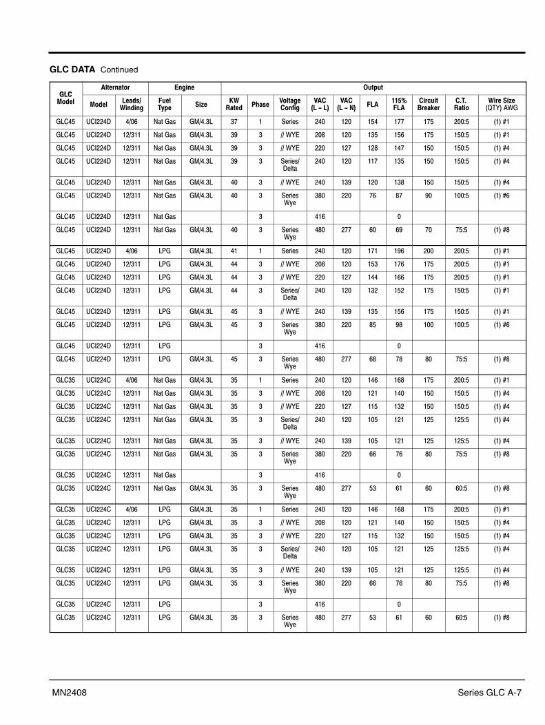
Series GLC A-7MN2408
GLC DATA Continued
�� �����!���� �!�$!� �����
�� %�3�� %�3��
���3�9)$!3$!�
����*"� �$<�
.)'���3 #����
/������ �!@$�
/� ,��7��-
/� ,��7��- ���
���B���
$�5�$�+���A��
=*=�'��$�
)$����$<��84K���5�
���0� ��"��0? 06�7 =���- �#60+�� �H � ����- �0� ��� ��0 �HH �H� ���>� ����D�
���0� ��"��0? ��6��� =���- �#60+�� �9 � 66�5K� ��: ��� ��� ��7 �H� ���>� ����D�
���0� ��"��0? ��6��� =���- �#60+�� �9 � 66�5K� ��� ��H ��: �0H ��� ���>� ����D0
���0� ��"��0? ��6��� =���- �#60+�� �9 � ����-6?���
�0� ��� ��H ��� ��� ���>� ����D0
���0� ��"��0? ��6��� =���- �#60+�� 0� � 66�5K� �0� ��9 ��� ��: ��� ���>� ����D0
���0� ��"��0? ��6��� =���- �#60+�� 0� � ����-5(�
�:� ��� H7 :H 9� ���>� ����D7
���0� ��"��0? ��6��� =���- � 0�7 �
���0� ��"��0? ��6��� =���- �#60+�� 0� � ����-5(�
0:� �HH 7� 79 H� H�>� ����D:
���0� ��"��0? 06�7 �*� �#60+�� 0� � ����- �0� ��� �H� �97 ��� ���>� ����D�
���0� ��"��0? ��6��� �*� �#60+�� 00 � 66�5K� ��: ��� ��� �H7 �H� ���>� ����D�
���0� ��"��0? ��6��� �*� �#60+�� 00 � 66�5K� ��� ��H �00 �77 �H� ���>� ����D�
���0� ��"��0? ��6��� �*� �#60+�� 00 � ����-6?���
�0� ��� ��� ��� �H� ���>� ����D�
���0� ��"��0? ��6��� �*� �#60+�� 0� � 66�5K� �0� ��9 ��� ��7 �H� ���>� ����D�
���0� ��"��0? ��6��� �*� �#60+�� 0� � ����-5(�
�:� ��� :� 9: ��� ���>� ����D7
���0� ��"��0? ��6��� �*� � 0�7 �
���0� ��"��0? ��6��� �*� �#60+�� 0� � ����-5(�
0:� �HH 7: H: :� H�>� ����D:
����� ��"��0� 06�7 =���- �#60+�� �� � ����- �0� ��� �07 �7: �H� ���>� ����D�
����� ��"��0� ��6��� =���- �#60+�� �� � 66�5K� ��: ��� ��� �0� ��� ���>� ����D0
����� ��"��0� ��6��� =���- �#60+�� �� � 66�5K� ��� ��H ��� ��� ��� ���>� ����D0
����� ��"��0� ��6��� =���- �#60+�� �� � ����-6?���
�0� ��� ��� ��� ��� ���>� ����D0
����� ��"��0� ��6��� =���- �#60+�� �� � 66�5K� �0� ��9 ��� ��� ��� ���>� ����D0
����� ��"��0� ��6��� =���- �#60+�� �� � ����-5(�
�:� ��� 77 H7 :� H�>� ����D:
����� ��"��0� ��6��� =���- � 0�7 �
����� ��"��0� ��6��� =���- �#60+�� �� � ����-5(�
0:� �HH �� 7� 7� 7�>� ����D:
����� ��"��0� 06�7 �*� �#60+�� �� � ����- �0� ��� �07 �7: �H� ���>� ����D�
����� ��"��0� ��6��� �*� �#60+�� �� � 66�5K� ��: ��� ��� �0� ��� ���>� ����D0
����� ��"��0� ��6��� �*� �#60+�� �� � 66�5K� ��� ��H ��� ��� ��� ���>� ����D0
����� ��"��0� ��6��� �*� �#60+�� �� � ����-6?���
�0� ��� ��� ��� ��� ���>� ����D0
����� ��"��0� ��6��� �*� �#60+�� �� � 66�5K� �0� ��9 ��� ��� ��� ���>� ����D0
����� ��"��0� ��6��� �*� �#60+�� �� � ����-5(�
�:� ��� 77 H7 :� H�>� ����D:
����� ��"��0� ��6��� �*� � 0�7 �
����� ��"��0� ��6��� �*� �#60+�� �� � ����-5(�
0:� �HH �� 7� 7� 7�>� ����D:

A-8 Series GLC MN2408
GLC DATA Continued
�� �����!���� �!�$!� �����
�� %�3�� %�3��
���3�9)$!3$!�
����*"� �$<�
.)'���3 #����
/������ �!@$�
/� ,��7��-
/� ,��7��- ���
���B���
$�5�$�+���A��
=*=�'��$�
)$����$<��84K���5�
����� ��"�:0� 06�7 =���- �#60+�� �� � ����- �0� ��� ��� �00 ��� ���>� ����D0
����� ��"��0� ��6��� =���- �#60+�� �� � 66�5K� ��: ��� ��0 ��� ��� ���>� ����D0
����� ��"��0� ��6��� =���- �#60+�� �� � 66�5K� ��� ��H 9: ��� ��� ���>� ����D0
����� ��"��0� ��6��� =���- �#60+�� �� � ����-6?���
�0� ��� 9� ��0 ��� ���>� ����D7
����� ��"��0� ��6��� =���- �#60+�� �� � 66�5K� �0� ��9 9� ��0 ��� ���>� ����D7
����� ��"��0� ��6��� =���- �#60+�� �� � ����-5(�
�:� ��� �H 77 H� H�>� ����D:
����� ��"��0� ��6��� =���- � 0�7 �
����� ��"��0� ��6��� =���- �#60+�� �� � ����-5(�
0:� �HH 0� �� 7� 7�>� ����D:
����� ��"�:0� 06�7 �*� �#60+�� �� � ����- �0� ��� ��� �00 ��� ���>� ����D0
����� ��"��0� ��6��� �*� �#60+�� �� � 66�5K� ��: ��� ��0 ��� ��� ���>� ����D0
����� ��"��0� ��6��� �*� �#60+�� �� � 66�5K� ��� ��H 9: ��� ��� ���>� ����D0
����� ��"��0� ��6��� �*� �#60+�� �� � ����-6?���
�0� ��� 9� ��0 ��� ���>� ����D7
����� ��"��0� ��6��� �*� �#60+�� �� � 66�5K� �0� ��9 9� ��0 ��� ���>� ����D7
����� ��"��0� ��6��� �*� �#60+�� �� � ����-5(�
�:� ��� �H 77 H� H�>� ����D:
����� ��"��0� ��6��� �*� � 0�7 �
����� ��"��0� ��6��� �*� �#60+�� �� � ����-5(�
0:� �HH 0� �� 7� 7�>� ����D:

Series GLC A-9MN2408
GLC Wire Size
Revision B 5�12�04��� ����!���;�
8 ���(� ���*)-�
#�3 35���� $��
�?"�*���� �3���(�Q����
�� � D�7 ��/�D�0��*?#�*�.�*A��� 0��� � D�7 ��/�D�0��*?#�*�.�*A��� 0��� � D�0 ��/�D:��*?#�*�.�*A��� 9�0� � D�� ��/�D:��*?#�*�.�*A��� 9��� � D�� ��/�D:��*?#�*�.�*A��� 9�7� � D: ��/�D:��*?#�*�.�*A��� 9�H� � D: ��/�D:��*?#�*�.�*A��� 9�:� � D7 ��/�D:��*?#�*�.�*A��� 9�9� � D7 ��/�D7��*?#�*�.�*A��� ������ � D7 ��/�D7��*?#�*�.�*A��� ������ � D7 ��/�D7��*?#�*�.�*A��� ������ � D0 ��/�D0��*?#�*�.�*A��� �H���� � D� ��/�D0��*?#�*�.�*A��� �H��H� � D� ��/�D���*?#�*�.�*A��� �7���� � D� ��/�D���*?#�*�.�*A��� �7���� � �6� ��/�D���*?#�*�.�*A��� �7���� � �6� ��/�D�6���*?#�*�.�*A��� ������ � 06� ��/�D�6���*?#�*�.�*A��� ������ � 06� ��/�D�6���*?#�*�.�*A��� 0��0�� � D� ��/�D06���*?#�*�.�*A��� 0H�0�� � �6� ��/�D�6���*?#�*�.�*A��� 7����� � �6� ��/�D�6���*?#�*�.�*A��� 7��7�� � �6� ��/�D�6���*?#�*�.�*A��� H��H�� � 06� ��/�D�6���*?#�*�.�*A��� :��:�� � �6� ��/�D06���*?#�*�.�*A��� 9��9�� � �6� ��/�D�6���*?#�*�.�*A��� ��7����� � �6� ��/�D�6���*?#�*�.�*A��� �������� � ��� ��/�D06���*?#�*�.�*A��� �0���0�� 0 06� 0�/�D06���*?#�*�.�*A��� �9���7�� 0 ��� 0�/�D06���*?#�*�.�*A��� �9������ � ��� ��/�D06���*?#�*�.�*A��� ��H����� 7 ��� 7�/�D06���*?#�*�.�*A��� �:������ H ��� 7�/�D�����*?#�*�.�*A��� ��:�0��� : ��� :�/�D�����*?#�*�.�*A��� 0�0�
Wiring Diagrams Wiring diagrams for these generators are contained on the following pages of this appendix.
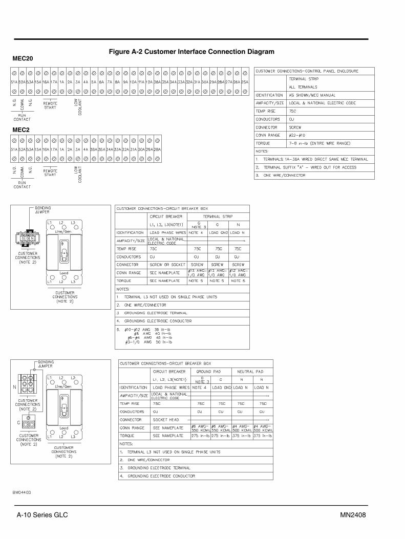
A-10 Series GLC MN2408
Figure A-2 Customer Interface Connection DiagramMEC20
MEC2

Series GLC A-11MN2408
Figure A-3 Customer Interface (w/o Breaker) Power Connection Diagram

A-12 Series GLC MN2408
Figure A-4 Single Phase � (w/o Breaker) Connection Diagram

Series GLC A-13MN2408
Figure A-5 Single Phase � One Breaker Connection Diagram

A-14 Series GLC MN2408
Figure A-6 Single Phase � Two Breaker Connection Diagram

Series GLC A-15MN2408
Figure A-7 Single Phase Connection Diagram (Wire 1/0 and Larger w/Breaker)

A-16 Series GLC MN2408
Figure A-8 Single Phase Connection Diagram (Wire 1/0 and Smaller w/Breaker)

Series GLC A-17MN2408
Figure A-9 Single Phase Connection Diagram (Wire 1/0 and Smaller w/o Breaker)

A-18 Series GLC MN2408
Figure A-10 Single Phase Connection Diagram (Wire Larger than 1/0 w/o Breaker)

Series GLC A-19MN2408
Figure A-11 Three Phase Connection Diagram

A-20 Series GLC MN2408
Figure A-12 Three Phase Connection Diagram with PMG

Series GLC A-21MN2408
Figure A-13 Three Phase Connection Diagram (Wire 1/0 and larger)
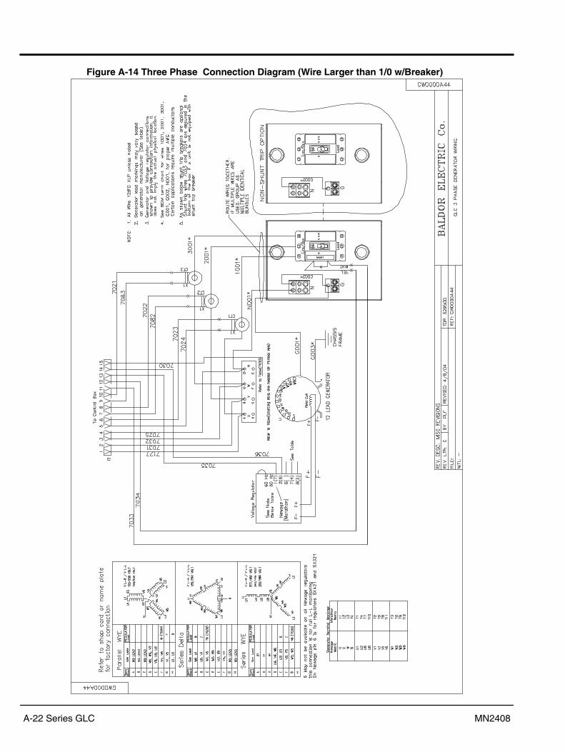
A-22 Series GLC MN2408
Figure A-14 Three Phase Connection Diagram (Wire Larger than 1/0 w/Breaker)

Series GLC A-23MN2408
Figure A-15 Three Phase Connection Diagram (Wire 1/0 and Smaller w/Breaker)

A-24 Series GLC MN2408
Figure A-16 Three Phase Connection Diagram (Wire Larger than 1/0 w/o Breaker)
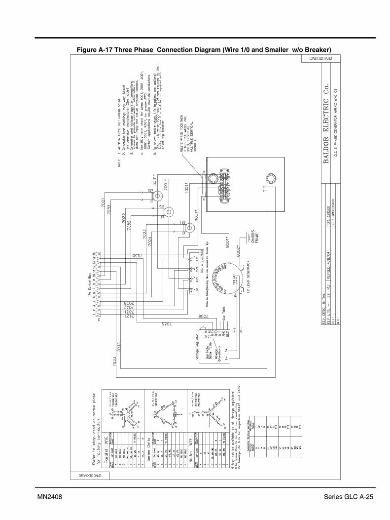
Series GLC A-25MN2408
Figure A-17 Three Phase Connection Diagram (Wire 1/0 and Smaller w/o Breaker)

A-26 Series GLC MN2408
Figure A-18 Control Box Connections with MEC20 Controller
Without Governor

Series GLC A-27MN2408
Figure A-19 Control Box Connections with MEC20 Controller & Governor
With Governor

A-28 Series GLC MN2408
Figure A-20 Control Box Connections with MEC2 Controller

Series GLC A-29MN2408
Figure A-21 Engine Wiring, Woodward 4.3L GM

A-30 Series GLC MN2408
Figure A-22 Engine Wiring, Woodward 5.7L GM

Series GLC A-31MN2408
Figure A-23 Engine Wiring, Woodward 8.1L GM

A-32 Series GLC MN2408

Series GLC A-33MN2408
Start�up Inspection Form It is required that both sides of this form be completed, signed where indicated andreturned to Baldor Generators within 30 days of initial Start�up and test. It is your responsibility to deliver copies to:
� Baldor Generators Factory � Baldor Distributor � Customer
For Standby, Automatic Emergency and Prime Power Generators
Distributor Information End User / Owner Information=3�> =3�>
�����--> �����-->
*)���> *)���>
#�����= 3���> O���= 3���>
_______��.*#�����_______��A;�����_______��*+�+ �����( ����� � -
_______��!5������_______��%���- _______��J%������_______���3�-+
��$���#�����D> ���������#�����D>
��$��������D> ��������������D>
�-��"��3-�"�-�������(�?-��� ���> �-���"��3-�"�-�������(�<�)��->
�!�$!��:���%����
#�4������� A)
/�������,#����7��7#����- ����!� �$��*�2= �$�#�������
)����*�2
�2�$�!�*�2%���� ������A)�
������3 �7� �7> >7� � � > :<#������� *�2= *�2=
����/ ��*��'��3����(>
�����-->
*)���>
?��>
4��)���>
� -��3����$�� ��>

A-34 Series GLC MN2408
� #��������7�� ��5A��$�� � �����7��#��5�3���
=��'��$)���3$�����3������-��$)� �-��$)� ����+�+ �)��!��)�������������2���$�����-�������)����������������������$���+
*������������$�3����������-��-+ 4)���4����$���-����2��-������)���?��2��- �'��( �3 -�����������(����������+
�����' ������-��-���������2������$��������!+ ����2��$����������-�����$)�+
�� ����&��-��<� ����'���;� ������( ���&����� ����+���)��!�'����!- ��$)����-�����--�(+
4)���, �3�������3�-������G���� ��������3����-���3�&��+
��������' ��������) -���� 3��$+ 4)���, �3����-�����������'��3���--����'����3$���(�'������$ -)���-(-��3+
���, �����'��2+ ���), !�������������2)������������-���, ���'����)��, �3���+
�����������2���-;�-�������������-+ <����$��������3��������!��������3�&��' -�-+
��������?��2���-;�-�������������-���� ���-������'��3����+ 4 �����2��-������������3����������������$�&����������-����-���2��3��)����$�&������+
����!�)�����-���������+ #�&��-2��)����13� �1+������)����$���-����G�� �+
�����������3���)��' ���-(-��3P��)��!�'�����!-+����������-�����--�(+
�'�����'�2�3� ��- ��)��!�������-- ���G��)��!�'�����!-+
<���� ���$-�' �����-��- �$-����-- ����'�0/7��;+��'����-- ���2�)��, ���&�� 3��-�&����+
��E -���)��-��������7�6��A;�'��, �����2�)�����������$�&��������7�6���A;�2�)�3��)����$�&�����+
�-�-�������&�&��-��������(�' ������$+ "'�-�����-� �-���� ��E -��������$������$�&������3� �+
��) -���������'����������������-�����������(��-������2�)� �����--&������-������-������-+
��E -���)�����&���$�����3��)��)�����3��-� ���+
��) -��-(-��3����3������������(��������������&��������(��'��) -��$-������ ���$+
�����)�� ���� �� ������$������)�-��������2������3�+
������-��������(�'�����2�)���������(���G��������(���������������)���$��+
���-��$��������3��������!�������������' -�-+
�����(��)�$���3 -������������(��-������G���������������)������(+������(�3 -�����' ��(��)�$�����������-���/ �+
#� ��(��&��/-������)�� ��� ������$���-) ���2���7:/H��A;�'��7��A;�$�������-�P��:/7��A;�'������A;�$��������-��-�+
����������������������-��'��������3���(������������������)����)����� �����!�������)���3��$���(�-����'��)�����-'��-2��)+
4�-�� ��3���-) �/��2�-����2�������-- �� ���2����������&�� �)$)���������3���� �� �<&��-�����-������RRRRRRA;�<�)��RRRRRR�
4)���3������&���$��G�'��, ���(��'��)�����-���3��)�-��)���'�4��G����3��-� ���+
CCC�(!����5���!3������!���!5�$�!���@�!$��CCC+�����43�-����� -��3��B-�.�, �-�����. ����3 �����*�2��< �$�+
(!����5������5����2���$!�����������$�!�D�2�$!��!�!5���'��)��-(-��3����3!��- ����)�(�)&����������3� �-+
Return this completed form to:
BALDOR GENERATORS3815 Oregon StreetOshkosh, WI 54902

Baldor District Offices�(*�&��*�*��
�."I<=�*A<�="N0������0�.?�*����*A<�="N ��I���:��0�*A<=�>�7��/0H�/�0�H��N>�7��/0H�/�070
���"�<.="��<���=�����70:����<4"����<##�.�� �������9��0�*A<=�>����/H�0/7HH���N>����/H��/�:�9
A�K5�.?����7��<.�����4.��4A�K5�.? �����90�0�*A<=�>����/H:�/99����N>����/H:�/99��
�<�<.�?<?�=%�.�����5���.��..K�*����?�=%�. ��<���:���0*A<=�>����/7��/���H��N>����/�9�/�HH�
�<==��4"��45���"=��<.?7���<�4A�4�.=*"J��.<�?5���"=��<.? ��4��709�*A<=�>����/�79/���0��N>����/�79/�0:�
��<."?�4�#*�6*��.4<�."�<6%".�"=�"���=?��9�7����4���4A��%�=��4�#*� ��������7��*A<=�>�:��/�0:/��H:��N>�:��/�0H/�9:0
��<.�"��4��=4�7��4��A=<�<�K�?.+���*A�.�44� �����������*A<=�>�HH�/HH�/H�����N>�HH�/HH�/H���
"��"=<"��A"���<H9��#"44���?."%�5<<?�?��� �"���7��9�*A<=�>�7��/H:H/97����N>�7��/H:H/�0�0
"=?"�=�"=?"�=�*<�"������5+�#"==��<4���4+"=?"�=�*<�"� �"=��07�0�*A<=�>���H/�07/������N>���H/�07/����:��/0�:/0�0�
"<5�?���#<"=���9���������%�+ ���"4��H?���#<"=�� �"���������*A<=�>����/�00/9997��N>����/�00/7��0
#�.K��=?���4"#<.�777����=4����.��.��.?��"4����/�0��J."?�� �#?+����H�*A<=�>�0��/�H9/������N>�0��/�H9/�7HH
#�����A���44��<�4<=��H��.<<J���4+5<.���4�. �#����7�7*A<=�>���:/:�0/�H�:��N>���:/:�0/��9�
#"�A"��=?�4.<"4��H:���4�.�"=��*<=?����%?+�4�.�"=��A�"�A4� �#"�0:���*A<=�>��:7/9H:/9:����N>��:7/9H:/9979
�.�=?�.�*"?�77:���#"���.<�?�=5�.�=?�.�*"?� �#"�09��0*A<=�>�7�7/H:�/�H:0��N>�7�7/H:�/�H::
#"==��<4�#"==��*<�"����:����04A��%�+�=<.4A.<��.� �#=������H0*A<=�>�H7�/0�:/�7����N>�H7�/0�:/0���
#"��<�."�4��<�"�0���"=?��4."���?."%�#�.K��=?�A�"�A4� �#<��7��0�*A<=�>���0/�9:/�:����N>���0/�9:/H77�
J�=�����"4K9���=�5�*��44��%����K�?.."%�.�"?� �#<���70���*A<=�>�:�7/�:H/��H���N>�:�7/�:H/�H��
=�5�K<.J����.=<=�����"��?."%�����.= �=K��������*A<=�>����/���/�0����N>����/���/99��
=<.4A���.<�"=��.��=��<.<�����.<4A�.5<<?�.<�?�.��=��<.< �=�����H0�7*�<��<N��7����.��=��<.< �=����H0�7*A<=�>���7/�H�/7��0��N>���7/�H�/77�:
<A"<�"=�"==�4"�9�����.A�.4��<�.4��"4�����A��.<= �JK��0��0:*A<=�>�:�9/�:7/������N>�:�9/�:7/�HH9
���%���=?:9�9��.��5�K�?."%�#���?<="� �<A�00��7*A<=�>����/07:/0HHH��N>����/07:/0HH:
<J��A<#��� 4����
�����4�?�5����"N�K �<J�H0��:*A<=�>�9�:/�77/9�����N>�9�:/�77/9��:
<.��<=*<.4��=?���9���5��%�.K��<�.44����4"= �<.�9H�7�*A<=�>����/79�/9�����N>����/79�/9���
*�==�K�%�="�*A"��?��*A"������4A<#�������A�#�#<."���A"�A5�K*�==���J�= �=O���:���*A<=�>�:�7/77�/�00���N>�:�7/77�/7�7�
*"44���.�A7�7A����44K�.<�?#<=.<�%"��� �*������07*A<=�>�0��/�:�/H�00��N>��0��/�:�/H���
4�==�����#�#*A"�0����5"=�A��4�.�.<�?#�#*A"� �4=����:��:*A<=�>�9��/�7�/������N>�9��/�7�/�9�0
4�N��A<��4<=070H�*"=��4"#��.���"4��D����A<��4<= �4N��HH�0�*A<=�>�H��/:9�/H�7���N>�H��/79�/0�0�
?�������0��8�����?����� �4N��H��0H*A<=�>���0/7�0/H�H���N>���0/7�0/::H0
<?����797:����4��<##�.��<?���� �4N��H9H7�*A<=�>�0��/�7H/�H�H��N>�0��/�7H/9:HH
�4�A���4���J���"4K������<�4A�#�"=��4.��4���4���J���"4K ��4�:0���*A<=�>�:��/:��/���H��N>�:��/:��/:9��
5"��<=�"=#"�5��J���H����<�4A��7�.?��4.��4=�5���.�"= �5"�������*A<=�>��7�/H:0/�90���N>��7�/H:0/����
"=4�.=�4"<=���������<.4��#"4A ��.���?<.�����4."���<�<.4��#"4A ��.��H�9��*A<=�>�0H9/707/0H����N>�0H9/70:/�:9��
��=�?�� �?#<=4<= �����.4�
0���/9���4.��4�?#<=4<= �����.4���47�7.:*A<=�>�H:�/0�0/09����N>�H:�/0�:/�7��
<�J%"��� �<=4�."<�H����<%�=4.K�.<�?<�J%"��� �<=4�."<��7A7.�*A<=�>�9��/:�9/������N>�9��/:�9/����
#<=4.��� �8������:00�5"��"�#��4.��4#<=4.��� �8������A�O�.�*A<=�>���0/9��/�H����N>���0/9��/:7�9
%�=�<�%�. ��."4"�A��<��#�"����:�J���4�5�K*<.4��<8�"4��# ����%����#�*A<=��7�0/0��/�:����N>�7�0/0��/����
5"=="*�� �#�="4<���0�*."=������4.��45"=="*�� �#�="4<���.���J�*A<=�>���0/90�/������N>���0/9�7/0���
���4.��"��="4�� �7��4�=4<=�.<�?��%�=�A"��� �=�5���0H �����4.��"�*A<=�>��7�������97H0��0����N>��7�������97H0��09�
�="4�: ���J����44��.<�?.<5%"��� �%"�4<."� ���H:�����4.��"�*A<=�>������9H���0�����N>������9H���0�77
�A"=��A�=�A�"�O"�A������"=������=4�..<<#�=<+��/���:�:�A<=��8"�<�.<�?�A�=�A�"�������*A<=�>�:7/��/700H��7���N>�:7/��/70�H:7��
������%�?<.���?<.���=4.<�#�."��.��"?�=�"���*"=�.���?����"I�*<�+����D00 �=%�+���=����%�?<.������%�?<. ���=4.<��#�."��*A<=�>��������::/���9��N>��������::/���:
�.�=��� �.���?��%���<=�9000��#�.<������=��."�*A<=�>�����0�����H9����N>�����0��99��:70
��.#�=K?"�����4.�������?/:�����J".�AA�"#�#�="�A ���.#�=K*A<=�>��09���:9��9���:�/����N>��09���:9��9���:�/�09�
"4��K��������.���#����-��<''��%������3� ����7:���#����-��2�;�����*A<=�>���0��9��70��99�����N>���0��9��7����7���
O�*�==�<�#"#������/��?�"#��A" �J�=���5�/J�K<J<A�#� ����/�:�0 �O�*�=�*A<=�>�:�/0�/0��/0��7��N>�:�/0�/0��/0��H
#SN"�<��%?+������.<*��.4< �J#+����T=��H�0� ����=�O��4< #SN"�<*A<=�>���/0HH/H7�/������N>���/0HH/H7�/����
*�=�#����?<.���?�#�."��9��9��:�: �I<=��7���4A�="�*�=�#U��"4K �.�*+�?��*�=�#U*A<=�>����H���7�/��0H��N>����H���7�/����
�"=��*<.����J�J"���J"4�.<�?��J���5�.�A<�����<#*��N�"=��*<.��0�H:7�*A<=�>��7���7�H00���H���N>��7���7�H0H��H�:
�5"4I�.��=?*<�4���A�H���A�4I�=�4.������9�A/:�0������.4A���=�5"4I�.��=?*A<=�>��0��������70H0H����N>��0��������7�9��90
4�"5�=.<<#�. ��� �=<+���0��A�=���A�=��.<�? ��A"A�"=�?"�4+4�"*�"����0�*A<=�>�::7/�/�:��/�777��N4+�:������N>�::7/�/�:��/�H�H
�="4�?�J"=�?<#7��."�4<��?"�4."��4"<=�*�.JA�5J��K�?."%��."�4<�������������+J+*A<=�>�00��0�0�:�������N>�00��0�0�:�9����

BALDOR GENERATORS3815 Oregon StreetOshkosh, WI 54902
(920) 236�4200 or (800) 872�7697Fax (920) 236�4219
www.baldor.com
© Baldor Electric CompanyMN2408
Printed in USA5/04 FAR200
WARNING:CALIFORNIA PROPOSITION 65 WARNING:
Engine exhaust from this product contains chemicals knownto the state of California to cause cancer, birth defects andother reproductive harm.
WARNING:CALIFORNIA PROPOSITION 65 WARNING:
Battery posts, terminals and related accessories are known tothe state of California to cause cancer, birth defects and otherreproductive harm.