Embed Size (px)
DESCRIPTION
nnnnnn
Citation preview
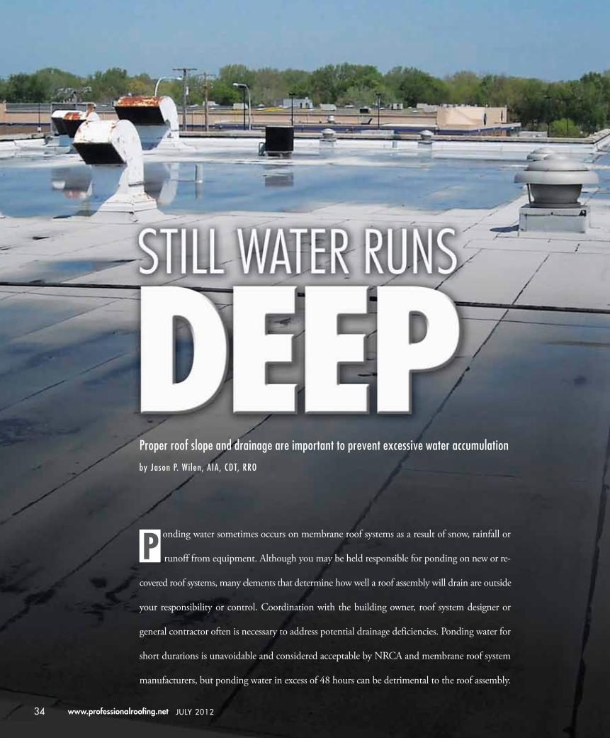
Proper roof slope and drainage are important to prevent excessive water accumulation
by Jason P. Wi len, AIA, CDT, RRO
onding water sometimes occurs on membrane roof systems as a result of snow, rainfall or
runoff from equipment. Although you may be held responsible for ponding on new or re-
covered roof systems, many elements that determine how well a roof assembly will drain are outside
your responsibility or control. Coordination with the building owner, roof system designer or
general contractor often is necessary to address potential drainage deficiencies. Ponding water for
short durations is unavoidable and considered acceptable by NRCA and membrane roof system
manufacturers, but ponding water in excess of 48 hours can be detrimental to the roof assembly.
P
34 www.professionalroofing.net JULY 2012

JULY 2012 Professional roofing 35
Slope and drainage requirements
NRCA recommends built-up, polymer-modified bitu-men, single-ply and liquid-applied roof membrane assemblies be designed to provide positive drainage. The NRCA Roofing Manual: Membrane Roof Sys-tems—2011 states: “The criterion for judging proper slope for drainage is that there be no ponding water on the roof 48 hours after a rain during conditions conducive to drying.”
Many building codes have a slope requirement for membrane roof systems. International Building Code,® 2012 Edition (IBC 2012) Section 1507—Require-ments for Roof Coverings states all membrane roof covering systems except coal-tar built-up roofs have a design slope minimum of one-fourth unit vertical in 12 units horizontal (2 percent slope) for drainage. Previous IBC editions have the same requirement.
For reroofing, though IBC 2012 requires materi-als and the application method used for re-covering or replacing an existing roof covering meet the same requirements for new construction, there is an excep-tion in Section 1510—Reroofing that states reroofing shall not be required to meet the minimum design slope requirement of one-quarter unit vertical in 12 units horizontal (2 percent slope) in Section 1507 for roof systems providing positive roof drainage. Previ-ous IBC editions have the same requirement.
Secondary or emergency drainage also is required by many building codes. IBC 2012 and IBC 2009 require secondary drainage be provided via roof drains or scuppers where the roof perimeter construc-tion extends above the roof in such a manner that water will be entrapped if the primary drains allow buildup for any reason. The section also states the roof drainage systems shall comply with the Interna-tional Plumbing Code® (IPC). Previous IBC versions do not contain specific language for secondary roof drainage, but they do require compliance with IPC. All editions of IPC contain secondary drainage lan-guage similar to the wording found in IBC 2012 and IBC 2009, so secondary drainage always has been an I-code requirement though it has not always been specifically stated in IBC.
In IPC 2012 Section 1108—Secondary (Emer-gency) Roof Drains, there is a requirement that secondary roof drain systems have the end point of discharge separate from the primary system. Previous versions of IPC have the same requirement.
Membrane roofing manufacturers generally rec-ommend a roof assembly have positive slope to drain and allow for short durations of ponding water. See Figure 1 for the ranges of manufacturers’ acceptable duration policies for ponding for various roof system types.
Providing positive slope
Many components contribute to a roof system’s slope, and some elements are outside your responsibility. The building owner and roof system designer are responsible for determining the roof assembly’s design and method of slope for drainage, and the roof deck installer is responsible for the installation of the struc-tural roof deck. You should inspect and accept roof deck surfaces only for their suitability for roof system installation. Substrate elements that may contribute to poor drainage areas should be corrected prior to acceptance.
Slope generally is incorporated into a roof assem-bly design by:• Sloping the structural framing or deck. This
method is more complex than a structure with no slope and requires coordination during the design process to ensure proper placement of drainage components such as roof drains and scuppers.
• Designing a tapered insulation system. This method can be used to meet the requirements for slope in new construction and reroofing projects, as well as in cases where a roof deck will not provide adequate slope to drain. The tapered insulation also can contribute to ther-mal resistance as part of meeting the minimum code requirement for insulation value.
• Using an insulating fill that can be sloped to drain. Lightweight insulating concrete, thermo-setting insulating fill and spray polyurethane foam (SPF) are examples of systems that can be installed over level or irregular roof assembly surfaces to achieve positive slope. Geographical location, structural considerations, compatibil-ity with other components and the geometry of the area to be sloped are considerations to determine the feasibility of this option.
• Proper location of roof drains, scuppers and gutters. For new construction, the roof system

36 www.professionalroofing.net JULY 2012
designer generally determines the location of drain-age elements. For reroofing, modifications to exist-ing drainage elements such as raising or lowering a drain or scupper may be necessary to provide proper drainage. Additional drains or scuppers also can be added but may be a challenge because of conflicts with existing building elements, integrat-ing existing building systems and cost.
• A combination of approaches. Most often, a com-bination of methods will be used to create adequate slope and drainage. In some cases, the choice is great-ly affected by economics depending on the build-ing and construction circumstances. Roof system designers and owners should select the method or combination of methods most appropriate for a roof assembly’s long-term performance.
Evaluating construction documents
For new construction and many reroofing projects, you will have the opportunity to examine construction docu-ments. As part of the document review process, you may want to evaluate the following items pertaining to slope and proper drainage:• Architectural roofing documents should indicate
roof slope and drainage elements, such as roof drains, scuppers or gutters.
• Mechanical documents should indicate placement of rooftop equipment. The equipment and associ-ated support elements should not interfere with anticipated drainage paths.
• Structural documents should indicate the roof deck type and may include sloping elements and mechanical equipment supports.
• Roof-related drawings should be coordinated. If roof system construction details are included, they
should be appropriate for the type of roof system being used.
• Roof-related specifications should include antici-pated roof system elements and be consistent with information shown on the drawings.
If the documents contain ambiguities or there is a lack of coordination among documents, ask the owner or roof system designer to determine the documents’ true intent before installing the roof system.
Substrate evaluation
Visual examination at the time of application is the most effective means of evaluating new and existing roof system substrates and may include routine measurements where applicable. Use common sense during the application evaluation and expect reasonable variance from specified amounts. Significant deviation from any particular crite-rion should be corrected before roof system installation occurs.
Inevitably, there will be humps and depressions result-ing from construction irregularities such as elevation dif-ferences at structural members’ top flanges, plane surface variations and field finishing of poured slabs or toppings. Also, structural framing and deck deflections can result in concave roof system surface areas. Roof loads such as mechanical equipment, snow, rooftop traffic and the roof system also can result in concave areas.
For steel roof decks, NRCA recommends installations conform to the requirements described in the Steel Deck Institute’s (SDI’s) Manual of Construction with Steel Deck and Design Manual for Composite Decks, Form Decks and Roof Decks. Many construction specifications reference these documents, as well.
Manual of Construction with Steel Deck provides the following direction regarding installing metal deck pan-els: “Maintaining rib or flute alignment across the struc-ture is very important. A snap chalk line should be used at reasonable intervals to assure proper alignment of deck panels. Panel cover widths must be maintained to achieve long straight runs of deck.”
For steel roof deck attachment to the underlying roof structure, welds or mechanical fasteners typically are used. SDI and FM Global provide two generally recognized but somewhat differing guidelines applicable to the attachment of steel roof decks. The specifics of steel roof deck attach- ment is beyond the scope of this article, but decks installed according to SDI or FM Global guidelines tend to be
Sample of manufacturers’ ponding water duration policiesSystem type
(number in parentheses indicates how many manufacturers were polled)
Manufacturer’s acceptable duration for ponding water to remain on a roof after a rain during conditions conducive to drying.a
Built-up—Asphalt (4) 48 hours
Built-up—Coal tar (2) Indefinite for hot-applied graveled systems
Polymer-modified bitumen (9) 48 hours
EPDM (5) 48 hours
Single-ply—TPO (6) 48 hours to indefinite
Single-ply—PVC (6) 48 hours to indefinite
Liquid-applied—PMMA (3) 48 hours to indefinite
aInformation based on documents available on manufacturer websites or telephone interviews.Many manufacturers will, on a case-by-case basis, allow different ponding durations based on specific system components.
Figure 1: Range of manufacturers’ acceptable duration for ponding water according to roof system type
JULY 2012 Professional roofing 37
more uniform and contain fewer construction irregu-larities than decks not observing SDI or FM Global guidelines.
In situations where you evaluate a steel roof deck and have reservations about accepting the roof deck surface because of deck panel misalignment or irregularities at supports, roof corners, deck perimeter, penetrations and side laps, you should bring the concerns to the owner, general contractor, roof system designer or roof deck installer to confirm the steel roof deck has been installed according to SDI, FM Global or other specified guide-line. Construction that is found to be outside the require-ments should be corrected before roof system installation. Section 1.4 of The NRCA Roofing Manual: Membrane Roof Systems—2011 contains additional information regarding best practices for steel roof deck installation.
The specific locations of irregularities and deflections are significant. Sometimes, imperfections will not result in a drainage issue. A hump in the substrate in an area where there will be a ridge or high point may be irrel-evant. Similarly, an area of deflection that corresponds to a drain location may not be cause for concern. An experienced roof system designer may design the roof drainage to minimize the effect of likely irregularities by, for example, strategically locating roof drains at structural midspans or roof system high points near equipment or deck penetrations.
When re-covering an existing roof system, the roof system designer (as directed by the owner) is responsible for analyzing the structural roof deck, including deck integrity, system compatibility, load capacity, drainage, moisture conditions, wind uplift and building code re-quirements. As part of this analysis, a means for correct-ing poor drainage areas or inadequate slope should be determined and executed before roof system application or be included as part of the roofing work scope.
Using tapered insulation to provide slope
Above-deck insulation is a component in most membrane roof assemblies. Tapered roof insulation can be used as part of above-deck insulation to provide slope for drain-age in the roof field. When deciding the amount of slope necessary for a tapered insulation system, a roof system designer should determine the net slope desired. The roof system designer should consider substrate conditions that may affect the roof system’s draining surface and specify a tapered insulation system with sufficient slope to
accommodate potential and existing deck deflections, deck irregularities and the actual roof deck slope.
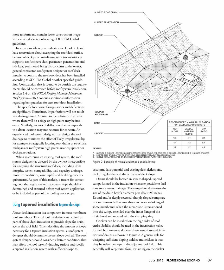
Drains should be located in square-shaped, tapered sumps formed in the insulation whenever possible to facil- itate roof system drainage. The sump should measure the size of the drain bowl’s diameter plus about 24 inches. Round and/or deeply recessed, sharply sloped sumps are not recommended because they can create wrinkling of some membranes when the membrane is transitioned into the sump, extended over the inner flange of the drain bowl and secured with the clamping ring.
Crickets can be installed on the high sides of roof curbs. Saddles should be used in the intersection valley formed by a two-way slope to divert runoff toward inte-rior roof drains as shown in Figure 2. A general rule for designing sufficient sloping saddles and crickets is that they be twice the slope of the adjacent roof field. This generally will keep water from remaining on the cricket
Figure 2: Example of typical cricket and saddle layout
38 www.professionalroofing.net JULY 2012
and saddle surface though some ponding water will occur in valleys of crickets and saddles.
NRCA recommends designers recognize the impor-tance of cricket and saddle geometry and valley slope. NRCA’s guidelines for length-to-width (L:W) ratios for saddles and crickets are provided in Figure 2. For ad-ditional figures and information, see Section 3.12—Tapered Insulation in The NRCA Roofing Manual: Membrane Roof Systems—2011.
Factory-tapered roof board insulation systems are com-posed of multiple layers of insulation boards that provide slope. The preformed tapered insulation boards are avail-able in several dimensions, typically 2 by 4 feet, 3 by 4 feet or 4 by 4 feet. The tapered boards and flat boards for fill are used to construct a sloped layout. Often, you will coordinate with the tapered insulation supplier to devise an efficient layout based on the roof system designer’s roof plan. The layout plan often will be part of the roof-ing submittal provided to the designer for review.
Because an insulation system comprises many pieces, some variation in installation is to be expected though finished surfaces of adjacent insulation boards should not be vertically offset more than 1/4 of an inch. Vertical offsets greater than 1/4 of an inch may be corrected by filling or leveling the gap with compatible material; add-ing tapered insulation as applicable; adding mechanical fasteners and plates; or, if shaving the insulation board, boards with facers should have the shaved area covered with a compatible material before ply or sheet installa-tion. Insulation boards also should be butted together.
Because of manufacturing tolerances, dimensional stability, variances during installation and the nature of insulation boards, some variation in joint spacing can be expected. Occasional gaps between boards not exceeding 1/4 of an inch are acceptable as long as the gaps are not continuous for more than the length of one insulation board. Gaps in excess of 1/4 of an inch should be filled with appropriate insulation board or compatible material.
When insulation is mechanically attached directly to a metal deck, thin insulation board edges parallel to the direction of the metal deck flutes should rest on the metal deck’s top flange. This is not as critical with thicker and denser insulation boards, such as 2-inch-thick polyiso-cyanurate, because it generally is strong enough to resist breaking when a cantilevered edge is subjected to foot traffic or other loads.
The use of tapered insulation for slope-to-drain may not necessarily result in complete, immediate drainage
of roof membrane surfaces. Some residual surface water may remain on the roof membrane surfaces at junctures, transitions and immediate drain areas following periods of precipitation. NRCA and most membrane roofing manufacturers consider there to be adequate drainage if the water has drained or evaporated within 48 hours after rainfall during conditions conducive to drying.
Post-installation issues
Preventable damage to installed roof membrane systems is far too common and can cause roof drainage issues, especially if the insulation is compressed causing a local-ized alteration in the roof system’s surface elevation. Completed roof membranes are not suitable as work platforms or staging areas for other trades. If construc-tion traffic is anticipated or inevitable, a temporary roof system can act as a sacrificial traffic surface, allowing for construction traffic and abuse until the primary weather-proofing membrane is installed. If repetitive rooftop traf-fic is anticipated, the use of permanent walkway paths should be considered to protect the finished membrane from damage in the trafficked areas.
Membrane roof systems sometimes are used as bases for roof-mounted equipment, such as communication, photovoltaic, mechanical equipment. Careful consider-ation must be given to the support, attachment and equip-ment placement so drainage is not compromised because of excessive structure deflection, interruption of drainage paths or damage caused by maintenance activities.
Final thoughts
Often, design decisions, construction sequencing or changes during construction are made without consider-ing the effects to roof drainage. Communicating with the owner, general contractor, other tradespeople and the roof system designer can greatly improve the roof system’s final drainage layout. Carefully reviewing existing conditions, bidding documents and thoroughly prepar-ing construction submittals also can improve the ultimate drainage performance of a membrane roof system, espe-cially if inconsistencies, errors and omissions can be cor-rected before roof system installation. 123
JaSon P. Wilen, aia, CDT, RRo, is an NRCA director of technical services.


![§TATJE ((J)JF IlNDilANA€¦ · ~m~~~mMmm~mmmm~mm~mmmm~m~~mmmm~ ~ ~ ~ ~ ii §TATJE ((J)JF IlNDilANA ~ ~ ~, lEXlECUT[V]E lDlEPARTMENT ~ i1 ITNlDllANAJPOLIT§ ~ ~ ~ ~ EXECUTIVE ORDER](https://img.pdfslide.us/doc/110x75/5f50db60d3dbb53f6466e480/tatje-jjf-ilndilana-mmmmmmmmmmmmmmmmmmmm-ii-tatje-jjf.jpg)