Embed Size (px)
Citation preview
HONDA .. mm
DD
@ 2001 Honda Mo to r Co., Ltd. -All Rights Reserved 2002
The engine exhaust from this product contains chemicals known to the State of California to cause cancer, birth defects, or other reproductive harm.
Keep this owner’s manual handy, so you can refer to it at any time. This owner’s manual is considered a permanent part of the outboard motor and should remain with the outboard motor if resold.
The information and specifications included in this publication were in effect at the time of approval for printing. Honda Motor Co., Ltd. reserves the right, however, to discontinue or change specifications or design at any time without notice and without incurring any obligation whatever. No part of this publication may be reproduced without written permission.
INTRODUCTION
Congratulations on your selection of a Honda outboard motor. We are certain you will be pleased with your purchase of one of the finest outboard motors on the market.
We want to help you get the best results from your new outboard motor and to operate it safely. This manual contains the information on how to do that; please read it carefully.
As you read this manual you will find information preceded by a
symbol. That information is intended to help you avoid damage to your outboard motor, other property, or the environment.
We suggest you read the warranty policy to fully understand its coverage and your responsibilities of ownership. The warranty policy is a separate document that should have been given to you by your dealer.
When your outboard motor needs scheduled maintenance, keep in mind that your Honda marine dealer is specially trained in servicing Honda outboard motors. Your Honda marine dealer is dedicated to your satisfaction and will be pleased to answer your questions and concerns.
0 2001 Honda Motor Co., Ltd. All Rights Reserved
1
INTRODUCTION
A FEW WORDS ABOUT SAFETY
Your safety and the safety of others are very important. And using this outboard motor safely is an important responsibility.
To help you make informed decisions about safety, we have provided operating procedures and other information on labels and in this manual. This information alerts you to potential hazards that could hurt you or others.
Of course, it is not practical or possible to warn you about all the hazards associated with operating or maintaining an outboard motor. You must use your own good judgment.
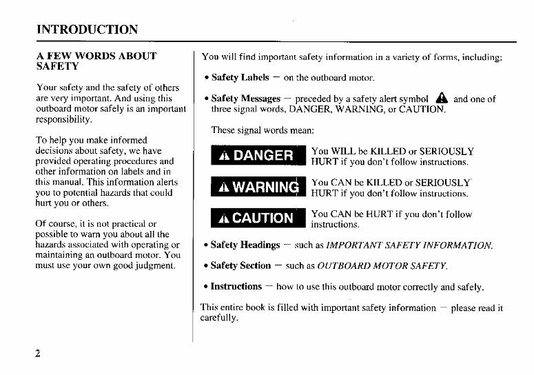
You will find important safety information in a variety of forms, including:
Safety Labels - on the outboard motor.
Safety Messages - preceded by a safety alert symbol A and one of three signal words, DANGER, WARNING, or CAUTION.
These signal words mean:
You WILL be KILLED or SERIOUSLY HURT if you don’t follow instructions.
You CAN be KILLED or SERIOUSLY’ HURT if you don’t follow instructions.
You CAN be HURT if you don’t follow instructions.
Safety Headings - such as IMPORTANT SAFETY INFORMATION.
Safety Section - such as OUTBOARD MOTOR SAFETY.
Instructions - how to use this outboard motor correctly and safely.
This entire book is filled with important safety information - please read it carefully.
2
CONTENTS
OUTBOARD MOTOR SAFETY .................................... 7 IMPORTANT SAFETY INFORMATION ................. 7 SAFETY LABEL LOCATIONS ................................. 9
CONTROLS AND FEATURES ................................... 10 CONTROL AND FEATURE
IDENTIFICATION CODES ................................. 10 COMPONENT AND CONTROL LOCATIONS ..... 11 CONTROLS ............................................................... 14 LH and LHT Types (tiller handle)
Electric Starter Button ............................................ 14 Engine Stop Switch and Switch Clip ..................... 14 Choke Knob ........................................................... 15 Throttle Grip ........................................................... 15 Throttle Friction Knob ........................................... 16 Gearshift Lever ...................................................... 16
LR. LRT and XRT Types (remote control) Ignition Switch (side-mount type) ......................... 16 Switch Clip and Emergency Stop Switch
(side-mount type) ............................................... 17 Fast Idle Lever (side-mount type) .......................... 18 GearshifdThrottle Control Lever
(side-mount type) ............................................... 18 Power TridTilt Switch (side-mount type) ............ 20
Common Controls Power Tilt Switch ................................................... 20 Manual Choke Knob .............................................. 21 Tilt Lever (gas assisted/LH and LR types) ............ 21 Manual Relief Valve .............................................. 22 Tilt Lock Lever ...................................................... 22 Engine Cover Latches ............................................ 22 Transom Angle Adjusting Rod .............................. 23 Trim Tab ................................................................. 23
Trim Meter (optional equipment) .......................... 24 Tachometer (optional equipment) .......................... 24 Fuel Gauge (optional equipment) .......................... 24
INDICATORS ............................................................ 25 Oil Pressure Indicator ............................................. 25 Overheating Indicator ............................................ 26 Cooling System Indicator ...................................... 27
INSTRUMENTS ........................................................ 24
3
CONTENTS
OTHER FEATURES ................................................. 27 Overrev Limiter ...................................................... 27 Anodes .................................................................... 27 Portable Fuel Tank (optional equipment) .............. 28 Fuel Cap Vent Knob (optional equipment) ........... 28 Fuel Priming Bulb .................................................. 29
BEFORE OPERATION ................................................. 30 ARE YOU READY TO GET UNDER WAY ? ...... 30 IS YOUR OUTBOARD MOTOR
READY TO GO ? ................................................. 30
OPERATION ................................................................. 32 SAFE OPERATING PRECAUTIONS ..................... 32
TRANSOM ANGLE ADJUSTMENT ...................... 33 PORTABLE FUEL TANK (optional equipment) ..... 34 FUEL HOSE CONNECTIONS ................................. 34 FUEL PRIMING ........................................................ 35
BREAK-IN PROCEDURE ........................................ 32
STARTING THE ENGINE ....................................... 35 LH and LHT Types (tiller handle) ......................... 35 LR. LRT and XRT Types (remote control) ........... 38
EMERGENCY STARTING ...................................... 40 STOPPING THE ENGINE ........................................ 43
Emergency Engine Stopping ................................. 43 Normal Engine Stopping 43
THROTTLE OPERATION ............................... 45 LH and LHT Types (tiller handle) ......................... 45 LR. LRT and XRT Types (remote control) ........... 46
STEERING ................................................................ 47 LH and LHT Types (tiller handle) ......................... 47 LR. LRT and XRT Types (remote control) ........... 47
CRUISING ................................................................. 48 SHALLOW WATER OPERATIONS ....................... 50 MOORING. BEACHING. LAUNCHING ................ 52
........................................ GEARSHIFTING AND
4
CONTENTS
SERVICING YOUR OUTBOARD MOTOR ............... 54 THE IMPORTANCE OF MAINTENANCE ............ 54 MAINTENANCE SAFETY ...................................... 55 TOOL KIT AND EMERGENCY STARTER
ROPE (optional equipment) ................................... 56 MAINTENANCE SCHEDULE ................................ 57 TRIM TAB ADJUSTMENT ..................................... 59 MANUAL RELIEF VALVE ..................................... 60 ENGINE COVER REMOVAL AND
INSTALLATION .............................................. 60 Engine Oil Level Check ......................................... 61 Engine Oil Change ................................................. 62
Lubrication Points .................................................. 65
REFUELING .............................................................. 68 FUEL RECOMMENDATIONS ................................ 69
Engine Oil Recommendations ............................... 64
Spark Plug Service ................................................. 66
Fuel Pump Filter Inspection and Replacement ...... 70
(optional equipment) .......................................... 72 Portable Fuel Tank and Filter Cleaning
Anode Replacement ............................................... 73 Propeller Replacement ........................................... 74
STORAGE ..................................................................... 75 STORAGE PREPARATION .................................... 75
Cleaning and Flushing ........................................... 75 Fuel ......................................................................... 78 Engine Oil .............................................................. 79
STORAGE PRECAUTIONS .................................... 80 REMOVAL FROM STORAGE ................................ 80
TRANSPORTING ......................................................... 81 WITH OUTBOARD MOTOR INSTALLED
WITH OUTBOARD MOTOR REMOVED .............................................................. ON BOAT 81
FROM BOAT ........................................................ 81
TAKING CARE OF UNEXPECTED PROBLEMS ........................................................... 82
BATTERY WILL NOT CHARGE AND ELECTRIC STARTER WILL NOT OPERATE .. 87
OIL PRESSURE INDICATOR LIGHT GOES OFF AND ENGINE SPEED IS LIMITED .................... 88
OVERHEATING INDICATOR LIGHT COMES ON AND ENGINE SPEED IS LIMITED ............. 89
SUBMERGED MOTOR ........................................... 90
5
CONTENTS
TECHNICAL AND CONSUMER INFORMATION ... 92 TECHNICAL INFORMATION ................................ 92
Serial Number Locations ....................................... 92 Carburetor Modification for High Altitude
Operation ............................................................ 93 Oxygenated Fuels ................................................... 94 Emission Control System Information .................. 95 Star Label ............................................................... 97 Specifications ......................................................... 99
CONSUMER INFORMATION .............................. 101
WIRING DIAGRAMS ................................................ 102
INDEX .......................................................................... 105
6
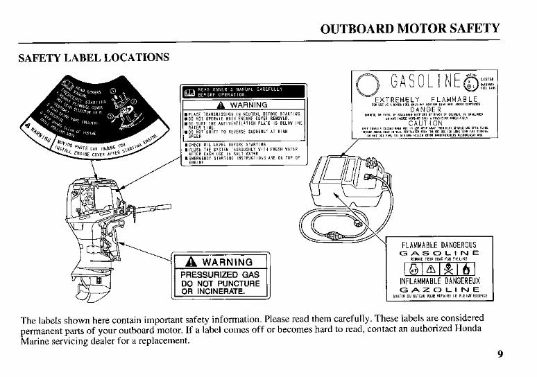
OUTBOARD MOTOR SAFETY
IMPORTANT SAFETY INFORMATION
Honda BF40A and BFSOA outboard motors are designed for use with boats that have a suitable manufacturer’s power recommendation. Other uses can result in injury to the operator or damage to the outboard motor and other property.
Most accidents can be prevented if you follow all instructions in this manual and on the outboard motor. The most common hazards are discussed below, along with the best way to protect yourself and others.
Operator Responsibility
0 It is the operator’s responsibility to provide the necessary safeguards to protect people and property. Know how to stop the engine quickly in case of emergency. Understand the use of all controls.
Stop the engine immediately if anyone falls overboard, and do not run the engine while the boat is near anyone in the water.
0 Always stop the engine if you must leave the controls for any reason.
0 Attach the emergency stop switch lanyard securely to the operator.
0 Always wear a PFD (Personal Flotation Device) while on the boat.
0 Familiarize yourself with all laws and regulations relating to boating and the use of outboard motors.
0 Be sure that anyone who operates the outboard motor receives proper instruction.
0 Be sure the outboard motor is properly mounted on the boat.
0 Do not remove the engine cover while the engine is running.
7
OUTBOARD MOTOR SAFETY
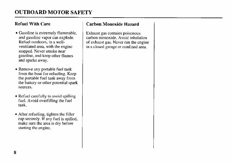
Refuel With Care
Gasoline is extremely flammable, and gasoline vapor can explode. Refuel outdoors, in a well- ventilated area, with the engine stopped. Never smoke near gasoline, and keep other flames and sparks away.
Remove any portable fuel tank from the boat for refueling. Keep the portable fuel tank away from the battery or other potential spark sources.
Refuel carefully to avoid spilling fuel. Avoid overfilling the fuel tank.
After refueling, tighten the filler cap securely. If any fuel is spilled, make sure the area is dry before starting the engine.
Carbon Monoxide Hazard
Exhaust gas contains poisonous carbon monoxide. Avoid inhalation of exhaust gas. Never run the engine in a closed garage or confined area.
8
6
3lBVWWVlzl Al3W3tllX
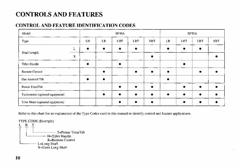
CONTROLS AND FEATURES CONTROL AND FEATURE IDENTIFICATION CODES
I Model I BF40A I BFSOA
Type LR XRT LRT LHT LR LH
L e e e e e Shaft Length
X e
Tiller Handle e e t' e
Remote Control
e Power TrindTilt
e e e Gas Assisted Tilt
e e e e e e
e e e e e e e e Tachometer (optional equipment)
e e e e e
I Trim Meter (optional equipment) e e
Refer to this chart for an explanation of the Type Codes used in this manual to identify control and feature applications.
TYPE CODE (Exam~le)
T=Power Tr idT i l t H=Tiller Handle R=Remote Control
L=Long Shaft X=Extra Long Shaft
10
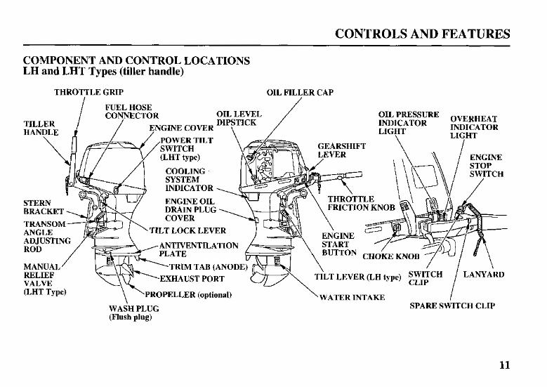
CONTROLS AND FEATURES
COMPONENT AND CONTROL LOCATIONS LH and LHT Types (tiller handle)
THROTTLE GRIP OIL FILLER CAP
INDICATOR
DRAIN PLUG
TILT LOCK LEVER
EXHAUST PORT TILT LEVER (LH type)
PROPELLER (optional) WATER INTAKE
WASH PLUG (Flush plug)
11
CONTROLS AND FEATURES
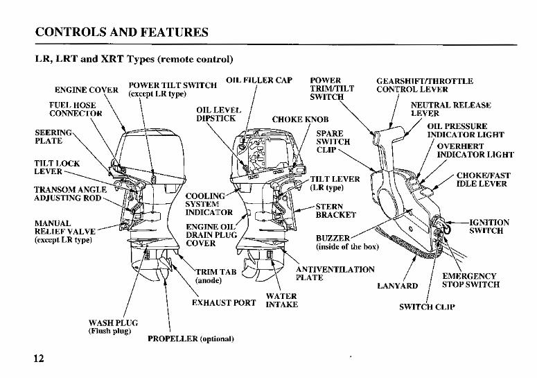
LR, LRT and XRT Types (remote control)
OIL FILLER CAP POWER GEARSHIFTmHROTTLE
OIL PRESSURE
CATOR LIGHT
TILT LEVER CHOKEEAST IDLE LEVER
TRANSOM AN ADJUSTING R
MANUAL RELIEF VALVE
I SWITCH CLIP
WASH PLUG (Flush plug)
PROPELLER (optional)
12
CONTROLS AND FEATURES
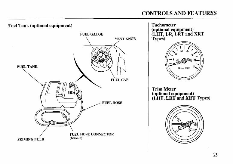
Fuel Tank (optional equipment)
FUEL GAUGE \ VENT KNOB
/ FUEL HOSE CONNECTOR PRIMING BULB (female)
Tachometer (optional equipment) (LHT, LR. LRT and XRT
Trim Meter (optional equipment) (LHT, LRT and XRT Types)
13
CONTROLS AND FEATURES
CONTROLS
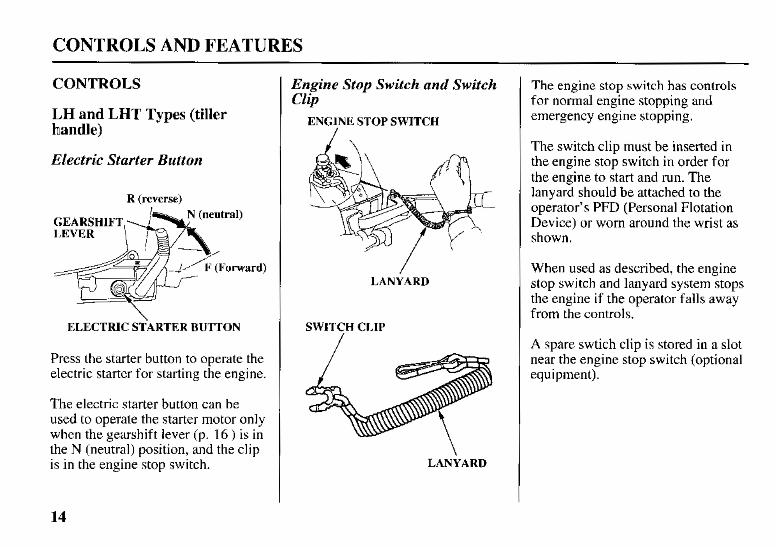
LH and LHT Types (tiller handle)
Electric Starter Button
R (reverse)
ELECTRIC STARTER BUTTON
Press the starter button to operate the electric starter for starting the engine.
The electric starter button can be used to operate the starter motor only when the gearshift lever (p. 16 ) is in the N (neutral) position, and the clip is in the engine stop switch.
Engine Stop Switch and Switch Clip
ENGINE STOP SWITCH
LANYARD
SWITCH CLIP
/
LANYARD
The engine stop switch has controls for normal engine stopping and emergency engine stopping.
The switch clip must be inserted in the engine stop switch in order for the engine to start and run. The lanyard should be attached to the operator’s PFD (Personal Flotation Device) or worn around the wrist as shown.
When used as described, the engine stop switch and lanyard system stops the engine if the operator falls away from the controls.
A spare swtich clip is stored in a slot near the engine stop switch (optional equipment).
14
CONTROLS AND FEATURES
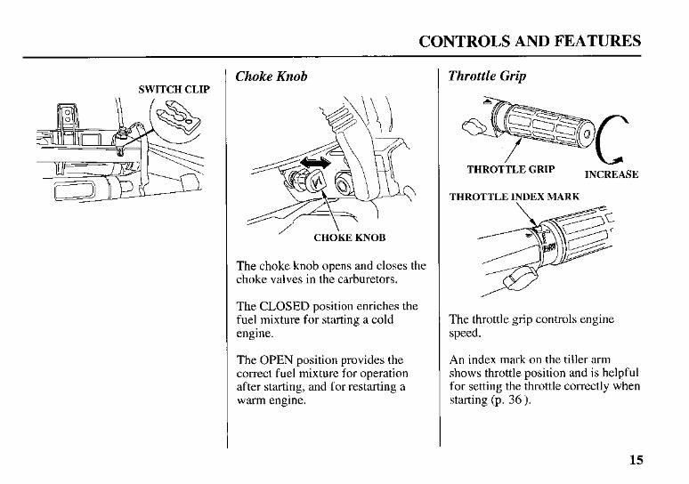
SWITCH CLIP Choke Knob
/ CHOKE KNOB
The choke knob opens and closes the choke valves in the carburetors.
The CLOSED position enriches the fuel mixture for starting a cold engine.
The OPEN position provides the correct fuel mixture for operation after starting, and for restarting a warm engine.
Throttle Grip
c THROTTLE GRIP INCREASE
THROTTLE INDEX MARK
The throttle grip controls engine speed.
An index mark on the tiller arm shows throttle position and is helpful for setting the throttle correctly when starting (p. 36 ).
15
CONTROLS AND FEATURES
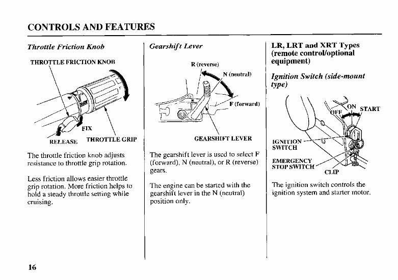
Throttle Friction Knob
THROTTLE FRICTION KNOB
The throttle friction knob adjusts resistance to throttle grip rotation.
Less friction allows easier throttle grip rotation. More friction helps to hold a steady throttle setting while cruising.
Gearshift Lever
R (reverse)
GEARSHIFT LEVER
The gearshift lever is used to select F (forward), N (neutral), or R (reverse) gears.
The engine can be started with the gearshift lever in the N (neutral) position only.
LR, LRT and XRT Types (remote controlloptional equipment)
Ignition Switch (side-mount tYP4
EMERGENCY STOP SWITCH
CLIP
The ignition switch controls the ignition system and starter motor.
16
CONTROLS AND FEATURES
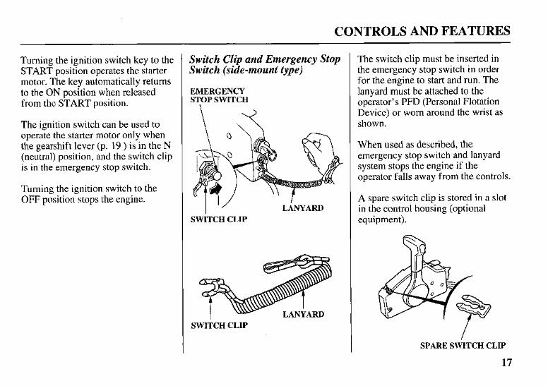
Turning the ignition switch key to the START position operates the starter motor. The key automatically returns to the ON position when released from the START position.
The ignition switch can be used to operate the starter motor only when the gearshift lever (p. 19 ) is in the N (neutral) position, and the switch clip is in the emergency stop switch.
Turning the ignition switch to the OFF position stops the engine.
Switch Clip and Emergency Stop Switch (side-mount type)
EMERGENCY STOP SWITCH
I ” LANYARD SWITCH CLIP
SWITCH CLIP
The switch clip must be inserted in the emergency stop switch in order for the engine to start and run. The lanyard must be attached to the operator’s PFD (Personal Flotation Device) or worn around the wrist as shown.
When used as described, the emergency stop switch and lanyard system stops the engine if the operator falls away from the controls.
A spare switch clip is stored in a slot in the control housing (optional equipment).
SPARE SWITCH CLIP
17
CONTROLS AND FEATURES
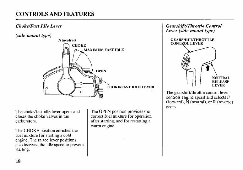
Choke/Fast Idle Lever
(side-mount type) N (neutral)
T IDLE 1 ,EVER
The choke/fast idle lever opens and closes the choke valves in the carburetors.
The CHOKE position enriches the fuel mixture for starting a cold engine. The raised lever positions also increase the idle speed to prevent stalling.
The OPEN position provides the correct fuel mixture for operation after starting, and for restarting a warm engine.
Gearshift/Throttle Control Lever (side-mount type)
GEARSHIFTRHROTTLE CONTROL LEVER
NEUTRAL RELEASE LEVER
The gearshifvthrottle control lever controls engine speed and selects F (forward), N (neutral), or R (reverse) gears.
18
CONTROLS AND FEATURES
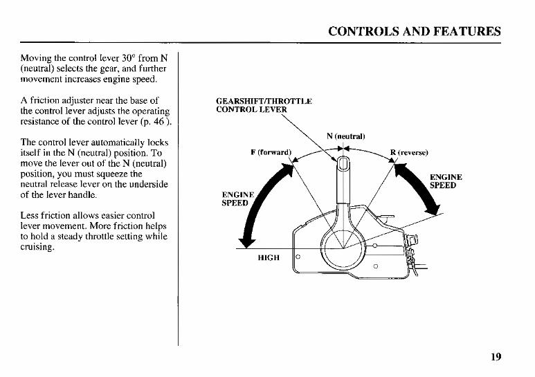
Moving the control lever 30" from N (neutral) selects the gear, and further movement increases engine speed.
A friction adjuster near the base of the control lever adjusts the operating resistance of the control lever (p. 46 ).
The control lever automatically locks itself in the N (neutral) position. To move the lever out of the N (neutral) position, you must squeeze the neutral release lever on the underside of the lever handle.
Less friction allows easier control lever movement. More friction helps to hold a steady throttle setting while cruising.
GEARSHIFTmHROTTLE CONTROL LEVER
\ N (neutral)
19
CONTROLS AND FEATURES
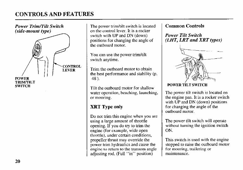
Power Trim/Tilt Switch
POWER TRIM/TILT SWITCH
The power tridtilt switch is located on the control lever. It is a rocker switch with UP and DN (down) positions for changing the angle of the outboard motor.
You can use the power tridtilt switch anytime.
Trim the outboard motor to obtain the best performance and stability (p. 48 ).
Tilt the outboard motor for shallow water operation, beaching, launching, or mooring.
XRT Type only
Do not trim this engine when you are using a large amount of throttle opening. If you do try to trim the engine (for example, wide open throttle), under certain conditions, propeller thrust may override the power trim hydraulics and cause the engine to return to the transom angle adjusting rod. (Full “in” position)
Common Controls
Power Tilt Switch (LHT, LRT and XRT types)
L - ~- .. .
POWER TILT SWITCH
The power tilt switch is located on the engine pan. It is a rocker switch with UP and DN (down) positions for changing the angle of the outboard motor.
The power tilt switch will operate without turning the ignition switch ON.
This switch is used with the engine stopped to raise the outboard motor for mooring, trailering or maintenance.
20
CONTROLS AND FEATURES
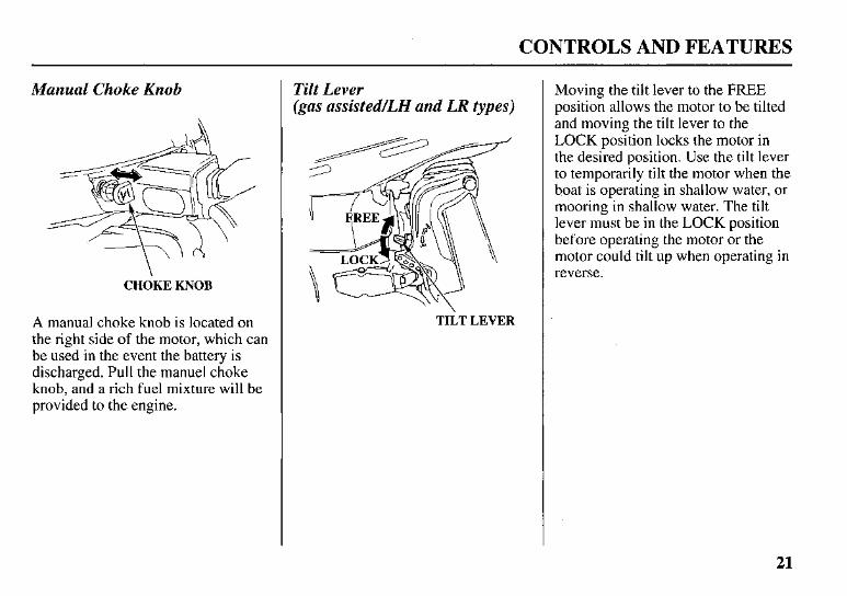
Manual Choke Knob
CHOKE KNOB
A manual choke knob is located on the right side of the motor, which can be used in the event the battery is discharged. Pull the manuel choke knob, and a rich fuel mixture will be provided to the engine.
Tilt Lever (gas assisted/LH and LR types)
TILT LEVER
Moving the tilt lever to the FREE position allows the motor to be tilted and moving the tilt lever to the LOCK position locks the motor in the desired position. Use the tilt lever to temporarily tilt the motor when the boat is operating in shallow water, or mooring in shallow water. The tilt lever must be in the LOCK position before operating the motor or the motor could tilt up when operating in reverse.
21
CONTROLS AND FEATURES
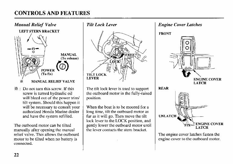
Manual Relief Valve LEFT STERN BRACKET
ER x)
MANUAL (To release)
k MANUAL RELIEF VALVE
% : Do not turn this screw. If this screw is turned hydraulic oil will bleed out of the power trim/ tilt system. Should this happen it will be necessary to consult your authorized Honda Marine dealer and have the system refilled.
The outboard motor can be tilted manually after opening the manual relief valve. This allows the outboard motor to be tilted when no battery is connected.
Tilt Lock Lever
T L
The tilt lock lever is used to support the outboard motor in the fully-raised position.
When the boat is to be moored for a long time, tilt the outboard motor as far as it will go. Then move the tilt lock lever to the LOCK position, and gently lower the outboard motor until the lever contacts the stern bracket.
Engine Cover Latches
FRONT
ENGINE COVER LATCH
REAR
ENGINE COVER
The engine cover latches fasten the engine cover to the outboard motor.
22
CONTROLS AND FEATURES
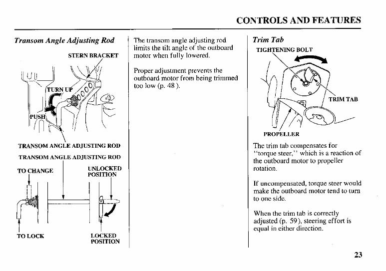
Transom Angle Adjusting Rod
STERN BRACKET
TRANSOM ANGLE ADJUSTING ROD
TRANSOM ANGLE ADJUSTING ROD
TO CHANGE UNLOCKED I POSITION
TO LOCK LOCKED POSITION
The transom angle adjusting rod limits the tilt angle of the outboard motor when fully lowered.
Proper adjustment prevents the outboard motor from being trimmed too low (p. 48 ).
Trim Tab TIGHTENING BOLT
PROPELLER
The trim tab compensates for “torque steer,” which is a reaction of the outboard motor to propeller rotation.
If uncompensated, torque steer would make the outboard motor tend to turn to one side.
When the trim tab is correctly adjusted (p. 59), steering effort is equal in either direction.
23
CONTROLS AND FEATURES
INSTRUMENTS
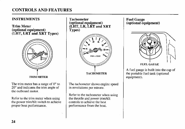
Trim Meter (optional equipment) (LHT, LRT and XRT Types)
TRIM'METER
The trim meter has a range of 0" to 20" and indicates the trim angle of the outboard motor.
Refer to the trim meter when using the power tridtilt switch to achieve proper boat performance.
Tachometer (optional equipment) (LHT, LR, LRT and XRT Types)
TACHOMETER
The tachometer shows engine speed in revolutions per minute.
Refer to the tachometer when using the throttle and power tridtilt controls to achieve the best performance from the boat.
Fuel Gauge (optional equipment)
FUEL GAUGE
A fuel gauge is built into the cap of the portable fuel tank (optional equipment).
24
CONTROLS AND FEATURES
INDICATORS
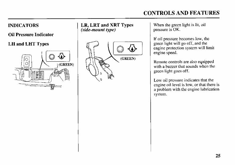
Oil Pressure Indicator
LH and LHT Types
LR, LRT and XRT Types (side-mount type)
When the green light is lit, oil pressure is OK.
If oil pressure becomes low, the green light will go off, and the engine protection system will limit engine speed.
Remote controls are also equipped with a buzzer that sounds when the green light goes off.
Low oil pressure indicates that the engine oil level is low, or that there is a problem with the engine lubrication system.
25
CONTROLS AND FEATURES
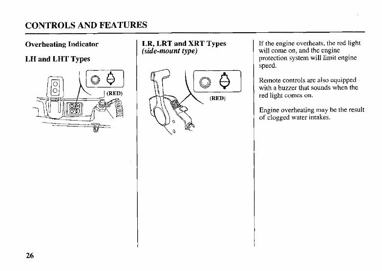
Overheating Indicator
LH and LHT Types
LR, LRT and XRT Types (side-mount type)
If the engine overheats, the red light will come on, and the engine protection system will limit engine speed.
Remote controls are also equipped with a buzzer that sounds when the red light comes on.
Engine overheating may be the result of clogged water intakes.
26
CONTROLS AND FEATURES
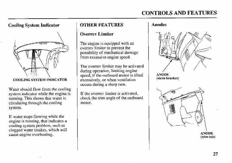
Cooling System Indicator
COOLING SYSTEM INDICATOR
Water should flow from the cooling system indicator while the engine is running. This shows that water is circulating through the cooling system.
If water stops flowing while the engine is running, that indicates a cooling system problem, such as clogged water intakes, which will cause engine overheating.
OTHER FEATURES
Overrev Limiter
The engine is equipped with an overrev limiter to prevent the possibility of mechanical damage from excessive engine speed.
The overrev limiter may be activated during operation, limiting engine speed, if the outboard motor is tilted excessively, or when ventilation occurs during a sharp turn.
If the overrev limiter is activated, check the trim angle of the outboard motor.
Anodes
ANODE (stern bracket)
ANODE (trim tab)
27
CONTROLS AND FEATURES
The anodes are made of a sacrificial material that helps to protect the outboard motor from corrosion.
There are two anodes on the gear case, one on the stern bracket, and another is the trim tab.
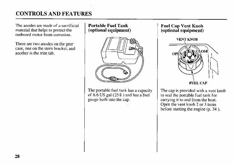
Portable Fuel Tank (optional equipment)
The portable fuel tank has a capacity of 6.6 US gal (25 .Q ) and has a fuel gauge built into the cap.
Fuel Cap Vent Knob (optional equipment)
VENT KNOB
FUEL CAP
The cap is provided with a vent knob to seal the portable fuel tank for carrying it to and from the boat. Open the vent knob 2 or 3 turns before starting the engine (p. 34 ).
28
CONTROLS AND FEATURES
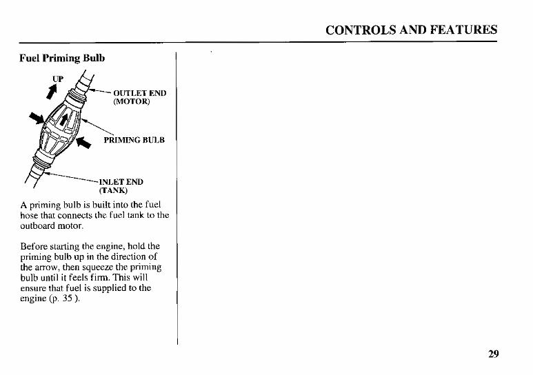
Fuel Priming Bulb
OUTLET END
I (TANK)
A priming bulb is built into the fuel hose that connects the fuel tank to the outboard motor.
Before starting the engine, hold the priming bulb up in the direction of the arrow, then squeeze the priming bulb until it feels firm. This will ensure that fuel is supplied to the engine (p. 35 ).
29
BEFORE OPERATION
ARE YOU READY TO GET UNDER WAY ?
Your safety is your responsibility. A little time spent in preparation will significantly reduce your risk of injury.
Knowledge
Read and understand this manual. Know what the controls do and how to operate them.
Familiarize yourself with the outboard motor and its operation before you get under way. Know what to do in case of emergencies.
Familiarize yourself with all laws and regulations relating to boating and the use of outboard motors.
Safety
Always wear a PFD (Personal Flotation Device) while on the boat.
Attach the emergency stop switch lanyard securely to your PFD or to your wrist.
IS YOUR OUTBOARD MOTOR READY TO GO ?
For your safety, and to maximize the service life of your equipment, it is very important to take a few moments before you operate the outboard motor to check its condition. Be sure to take care of any problem you find, or have your authorized Honda Marine dealer correct it, before you operate the outboard motor.
Improperly maintaining this outboard motor, or failing to correct a problem before operation, could cause a malfunction in which you could be seriously injured.
Always perform a preoperation inspection before each operation, and correct any problem.
Before beginning your preoperation checks, be sure the ignition switch is in the OFF position.
30
BEFORE OPERATION
Safety Inspection
Look around the outboard motor for signs of oil or gasoline leaks.
If you are using the portable fuel tank (optional equipment), make sure it is in good condition and properly secured in the boat (p. 34 ).
Check that the fuel hose is undamaged and properly connected (p. 34 ).
Wipe up any spills before starting the engine.
Check the stern bracket to be sure the outboard motor is securely installed.
Check that all controls are operating properly.
Replace any damaged parts.
Check that all fasteners are in place and securely tightened.
Maintenance Inspection
Check the engine oil level (p. 61 ). Running the engine with a low oil level can cause engine damage.
Check to be sure the propeller is undamaged, and the castle nut is secured with the cotter pin (p. 74 ).
Check that the anodes are securely attached to the gear case (p. 73 ) and are not excessively worn. The anodes help to protect the outboard motor from corrosion.
Make sure the tool lu t (optional equipment) and emergency starter rope are onboard (p. 56 ). Replace any missing items.
Check the fuel level in the fuel tank (p. 68 ).
31
OPERATION
SAFE OPERATING PRECAUTIONS
To safely realize the full potential of this outboard motor, you need a complete understanding of its operation and a certain amount of practice with its controls.
Before operating the outboard motor for the first time, please review the IMPORTANT SAFETY INFORMATION on page 7 and the chapter titled BEFORE OPERATION.
For your safety, avoid starting or operating the engine in an enclosed area. Your engine’s exhaust contains poisonous carbon monoxide gas which can collect rapidly in an enclosed area and cause illness or death.
BREAK-IN PROCEDURE
Break-in period: 10 hours
Proper break-in operation allows the moving parts to wear in smoothly for best performance and long service life.
First 15 minutes: Run the engine at trolling speed. Use the minimum throttle opening necessary to operate the boat at a safe trolling speed.
Next 45 minutes: Run the engine up to a maximum of 2,000 to 3,000 rpm, which is about 10% to 30% of maximum throttle opening.
Next 60 minutes: Run the engine up to a maximum of 4,000 to 5,000 rpm, which is about 50% to 80% of maximum throttle opening.
Short full-throttle bursts are OK, but do not operate the engine continuously at full throttle.
For boats that plane easily, bring the boat up on plane, and then reduce the throttle opening to the recommended rpm range.
Next 8 hours: Do not run the engine at full throttle for more than 5 minutes at a time.
32
OPERATION
TRANSOM ANGLE ADJUSTMENT
STERN BRACKET
TRANSOM ANGLE ADJUSTING ROD
TRANSOM ANGl
TO CHANGE
LE ADJUSTING ROD I
TO LOCK LOCKED POSITION
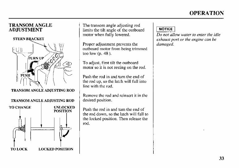
The transom angle adjusting rod limits the tilt angle of the outboard motor when fully.lowered.
Proper adjustment prevents the outboard motor from being trimmed too low (p. 48).
To adjust, first tilt the outboard motor so it is not resting on the rod.
Push the rod in and turn the end of the rod up, so the latch will fall into line with the rod.
Remove the rod and reinsert it in the desired position.
Push the rod in and turn the end of the rod down, so the latch will fall to the locked position. Then release the rod.
piEiE-l Do not allow water to enter the idle exhaust port or the engine can be damaged.
33
OPERATION
PORTABLE FUEL TANK (optional equipment)
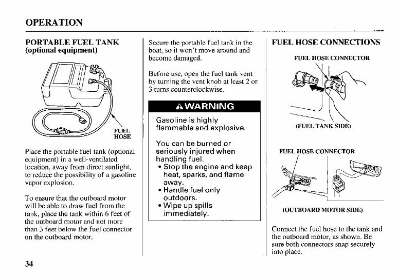
Place the portable fuel tank (optional equipment) in a well-ventilated location, away from direct sunlight, to reduce the possibility of a gasoline vapor explosion.
To ensure that the outboard motor will be able to draw fuel from the tank, place the tank within 6 feet of the outboard motor and not more than 3 feet below the fuel connector on the outboard motor.
Secure the portable fuel tank in the boat, so it won’t move around and become damaged.
Before use, open the fuel tank vent by turning the vent knob at least 2 or 3 turns counterclockwise.
Gasoline is highly flammable and explosive.
You can be burned or seriously injured when handling fuel.
Stop the engine and keep heat, sparks, and flame away. Handle fuel only outdoors. Wipe up spills immediately.
FUEL HOSE CONNECTIONS
FUEL HOSE CONNECTOR \I I
(FUEL TANK SIDE)
FUEL HOSE CONNECTOR
(OUTBOARD MOTOR SIDE)
Connect the fuel hose to the tank and the outboard motor, as shown. Be sure both connectors snap securely into place.
34
OPERATION
FUEL PRIMING
OUTLET END (MOTOR)
PRIMING BULB
INLET END (TANK)
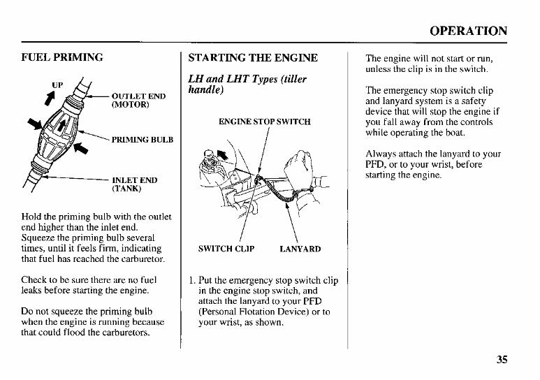
Hold the priming bulb with the outlet end higher than the inlet end. Squeeze the priming bulb several times, until it feels firm, indicating that fuel has reached the carburetor.
Check to be sure there are no fuel leaks before starting the engine.
Do not squeeze the priming bulb when the engine is running because that could flood the carburetors.
STARTING THE ENGINE
LH and LHT Types (tiller handle)
ENGINE STOP SWITCH
SWITCH CLIP LANYARD
1. Put the emergency stop switch clip in the engine stop switch, and attach the lanyard to your PFD (Personal Flotation Device) or to your wrist, as shown.
The engine will not start or run, unless the clip is in the switch.
The emergency stop switch clip and lanyard system is a safety device that will stop the engine if you fall away from the controls while operating the boat.
Always attach the lanyard to your PFD, or to your wrist, before starting the engine.
35
OPERATION
GEARSIFT LEVER
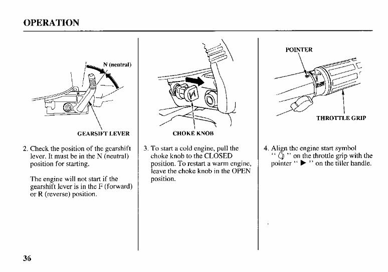
2. Check the position of the gearshift lever. It must be in the N (neutral) position for starting.
The engine will not start if the gearshift lever is in the F (forward) or R (reverse) position.
CHOKE KNOB
3. To start a cold engine, pull the choke knob to the CLOSED position. To restart a warm engine, leave the choke knob in the OPEN position.
POIYTER
I THROTTLE GRIP
4. Align the engine start symbol " " on the throttle grip with the pointer " b " on the tiller handle.
36
OPERATION
START BUTTON
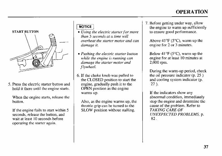
5. Press the electric starter button and hold it there until the engine starts.
When the engine starts, release the button.
If the engine fails to start within 5 seconds, release the button, and wait at least 10 seconds before operating the starter again.
-1 Using the electric starter f or more than 5 seconds at a time will overheat the starter motor and can damage it.
Pushing the electric starter button while the engine is running can damage the starter motor and flywheel.
6. If the choke knob was pulled to the CLOSED position to start the engine, gradually push it to the OPEN position as the engine warms up.
Also, as the engine warms up, the throttle grip can be turned to the SLOW position without stalling.
7. Before getting under way, allow the engine to warm up sufficiently to ensure good performance.
Above 41 "F (5"C), warm up the engine for 2 or 3 minutes.
Below 41°F (5"C), warm up the engine for at least 10 minutes at 2,000 rpm.
During the warm-up period, check the oil pressure indicator (p. 25 ) and cooling system indicator (p. 27 ).
If the indicators show any abnormal condition, immediately stop the engine and determine the cause of the problem. Refer to TAKING CARE OF UNEXPECTED PROBLEMS, p. 82 .
37
OPERATION
LR, LRT and XRT Types (remote control)
Side-Mount Type
EMERGENCY STOP SWITCH
\
SWITCH CLIP LANYARD
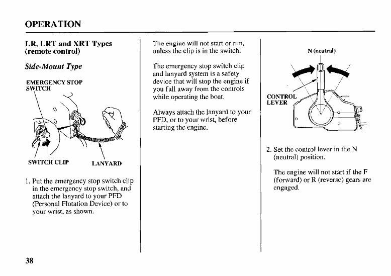
1 . Put the emergency stop switch clip in the emergency stop switch, and attach the lanyard to your PFD (Personal Flotation Device) or to your wrist, as shown.
The engine will not start or run, unless the clip is in the switch.
The emergency stop switch clip and lanyard system is a safety device that will stop the engine if you fall away from the controls while operating the boat.
Always attach the lanyard to your PFD, or to your wrist, before starting the engine.
N (neutral) I
2. Set the control lever in the N (neutral) position.
The engine will not start if the F (forward) or R (reverse) gears are engaged.
38
OPERATION
CHOKE MAXIMUM FAST
CHOKElFAST IDLE LEVER
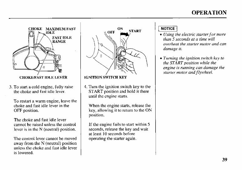
3. To start a cold engine, fully raise the choke and fast idle lever.
To restart a warm engine, leave the choke and fast idle lever in the OFF position.
The choke and fast idle lever cannot be raised unless the control lever is in the N (neutral) position.
The control lever cannot be moved away from the N (neutral) position unless the choke and fast idle lever is lowered.
IGNITION SWITCH KEY
4. Turn the ignition switch key to the START position and hold it there until the engine starts.
When the engine starts, release the key, allowing it to return to the ON position.
If the engine fails to start within 5 seconds, release the key and wait at least 10 seconds before operating the starter again.
-1 0 Using the electric starter f or more
than 5 seconds at a time will overheat the starter motor and can damage it.
Turning the ignition switch key to the START position while the engine is running can damage the starter motor and f lywheel.
39
OPERATION
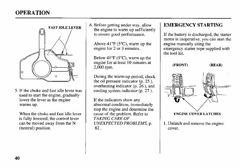
~ FAST IDLE LEVER
/
5. If the choke and fast idle lever was used to start the engine, gradually lower the lever as the engine warms up.
When the choke and fast idle lever is fully lowered, the control lever can be moved away from the N (neutral) position.
6. Before getting under way, allow the engine to warm up sufficiently to ensure good performance.
Above 41°F (5"C), warm up the engine for 2 or 3 minutes.
Below 41°F (5"C), warm up the engine for at least 10 minutes at 2,000 rpm.
During the warm-up period, check the oil pressure indicator (p. 25 ), overheating indicator (p. 26 ), and cooling system indicator (p. 27 ).
If the indicators show any abnormal condition, immediately stop the engine and determine the cause of the problem. Refer to TAKING CARE OF UNEXPECTED PROBLEMS, p. 82.
EMERGENCY STARTING
If the battery is discharged, the starter motor is inoperative, you can start the engine manually using the emergency starter rope supplied with the tool kit.
ENGINE COVER LATCHES "
1. Unlatch and remove the engine cover.
OPERATION
WA
FLYWHEEL COVER
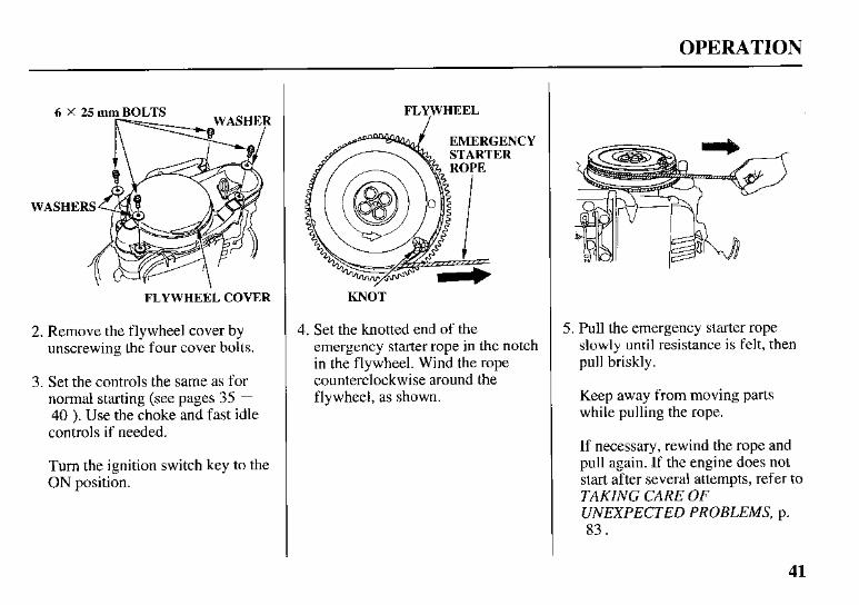
2. Remove the flywheel cover by unscrewing the four cover bolts.
3. Set the controls the same as for normal starting (see pages 35 - 40 ). Use the choke and fast idle controls if needed.
Turn the ignition switch key to the ON position.
FLYWHEEL
CY
KNOT
4. Set the knotted end of the emergency starter rope in the notch in the flywheel. Wind the rope counterclockwise around the flywheel, as shown.
5. Pull the emergency starter rope slowly until resistance is felt, then pull briskly.
Keep away from moving parts while pulling the rope.
If necessary, rewind the rope and pull again. If the engine does not start after several attempts, refer to TAKING CARE OF UNEXPECTED PROBLEMS, p. 8 3 .
41
OPERATION
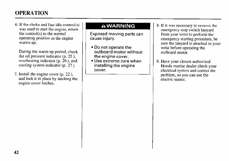
6. If the choke and fast idle control(s) was used to start the engine, return the control(s) to the normal operating position as the engine warms up.
During the warm-up period, check the oil pressure indicator (p. 25 ), overheating indicator (p. 26 ), and cooling system indicator (p. 27).
7. Install the'engine cover (p. 22 ), and lock it in place by latching the engine cover latches.
Exposed moving parts can cause injury.
Do not operate the outboard motor without the engine cover. Use extreme care when installing the engine cover.
8. If it was necessary to remove the emergency stop switch lanyard from your wrist to perform the emergency starting procedure, be sure the lanyard is attached to your wrist before operating the outboard motor.
9. Have your closest authorized Honda marine dealer check your electrical system and correct the problem, so you can use the electric starter.
42
OPERATION
STOPPING THE ENGINE
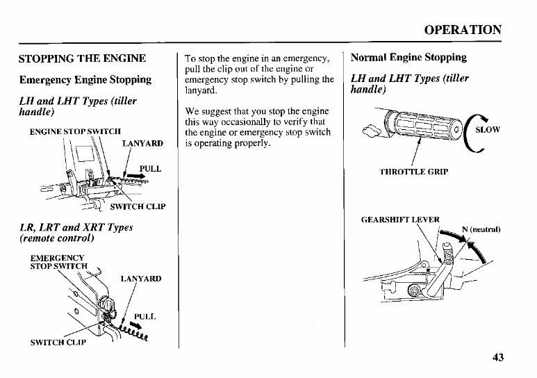
Emergency Engine Stopping
LH and LHT Types (tiller handle)
ENGINE STOP SWITCH
LL
7r\- 3 SWITCH CLIP
LR, LRT and XRT Types (remote control)
EMERGENCY
To stop the engine in an emergency, pull the clip out of the engine or emergency stop switch by pulling the lanyard.
We suggest that you stop the engine this way occasionally to verify that the engine or emergency stop switch is operating properly.
Normal Engine Stopping
LH and LHT Types (tiller handle)
THROTTLE GRIP
GEARSHIFT LEVER
43
OPERATION
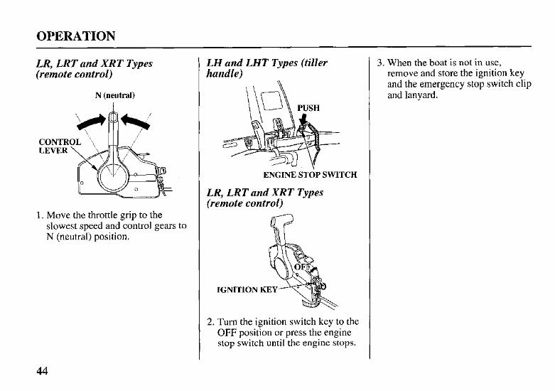
LR, LRT and XRT Types (remote control)
N (neutral) I
1. Move the throttle grip to the slowest speed and control gears to N (neutral) position.
LH and LHT Types (tiller handle)
ENGINE STOP SWITCH
LR, LRT and XRT TJpes (remote control)
IGNITION
2. Turn the ignition switch key to the OFF position or press the engine stop switch until the engine stops.
3. When the boat is not in use, remove and store the ignition key and the emergency stop switch clip and lanyard.
44
OPERATION
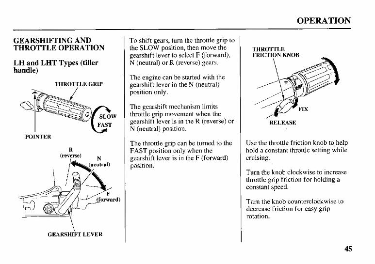
GEARSHIFTING AND THROTTLE OPERATION
LH and LHT Types (tiller handle)
THROTTLE GRIP
POINTER
R (reverse)
I N
GEARSHIFT LEVER
To shift gears, turn the throttle grip to the SLOW position, then move the gearshift lever to select F (forward), N (neutral) or R (reverse) gears.
The engine can be started with the gearshift lever in the N (neutral) position only.
The gearshift mechanism limits throttle grip movement when the gearshift lever is in the R (reverse) or N (neutral) position.
The throttle grip can be turned to the FAST position only when the gearshift lever is in the F (forward) position.
THROTTLE FRICTION KNOB
RELEASE
Use the throttle friction knob to help hold a constant throttle setting while cruising.
Turn the knob clockwise to increase throttle grip friction for holding a constant speed.
Turn the knob counterclockwise to decrease friction for easy grip rotation.
45
OPERATION
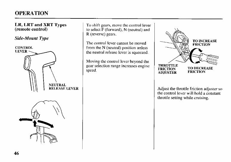
LR, LRT and XRT Types (remote control)
Side-Mount Type
CONTROL LEVER
NEUTRAL RELEASE LEVER
To shift gears, move the control lever to select F (forward), N (neutral) and R (reverse) gears.
The control lever cannot be moved from the N (neutral) position unless the neutral release lever is squeezed.
Moving the control lever beyond the gear selection range increases engine speed. FRICTION TO DECREASE
ADJUSTER FRICTION
Adjust the throttle friction adjuster so the control lever will hold a constant throttle setting while cruising.
46
OPERATION
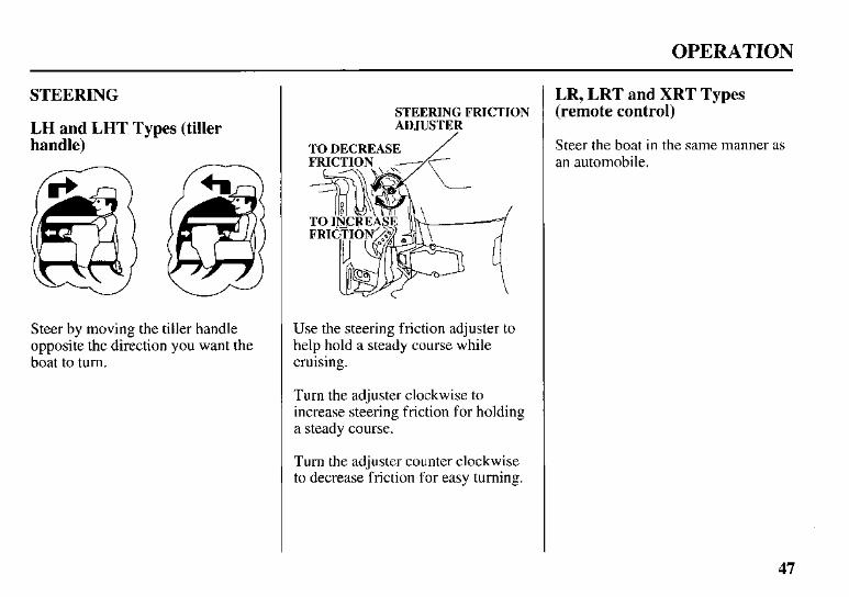
STEERING
LH and LHT Types (tiller handle)
Steer by moving the tiller handle opposite the direction you want the boat to turn.
STEERING FRICTION ADJUSTER
TO DECREASE
Use the steering friction adjuster to help hold a steady course while cruising.
Turn the adjuster clockwise to increase steering friction for holding a steady course.
Turn the adjuster counter clockwise to decrease friction for easy turning.
LR, LRT and XRT Types (remote control)
Steer the boat in the same manner as an automobile.
47
OPERATION
CRUISING
Engine Speed
For best fuel economy, limit the throttle opening to 80%. Use the throttle friction control (p. 45 and 46 ) to help you hold a steady speed.
For rough water conditions or large waves, slow down to prevent the propeller from rising out of the water.
The engine is equipped with an overrev limiter to prevent the possibility of mechanical damage from excessive engine speed.
If, for example, the outboard motor is tilted excessively, or ventilation occurs during a sharp turn, the engine may overrev, activating the overrev limiter.
If engine speed becomes unstable at high speed due to activation of the overrev limiter, reduce speed and check the trim angle of the outboard motor.
Trim
LHT and LRT Types
Install the outboard motor at the best trim angle for stable cruising and maximum power.
Trim angle too large: Incorrect causes boat to “squat’ ’.
Trim angle too small: Incorrect causes boat to “plow”.
LRT and XRT Types
Use the power tridtilt switch to trim the outboard motor for the best performance and stability.
You can use the power tridtilt switch at any time, whether the boat is under way or stopped.
Press the UP or DN (down) side of the switch to adjust the angle of the outboard motor.
Refer to the trim meter (p. 24 ) for an indication of whether the boat is trimmed high or low.
XRT Type only
Do not trim this engine when you are using a large amount of throttle opening (p. 20 ).
48
OPERATION
LRT and XRT Types
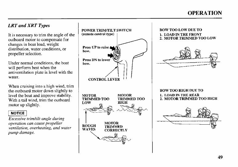
It is necessary to trim the angle of the outboard motor to compensate for changes in boat load, weight distribution, water conditions, or propeller selection.
Under normal conditions, the boat will perform best when the antiventilation plate is level with the water.
When cruising into a high wind, trim the outboard motor down slightly to level the boat and improve stability. With a tail wind, trim the outboard motor up slightly.
Excessive trimftilt angle during operation can cause propeller ventilation, overheating, and water pump damage.
POWER TRIM/TILT SWITCH (remote control type) I
Press bow.
Press bow.
UP to
DN to 1 lower raik CONTROLLEVER 1 I
MOTOR MOTOR TRIMMED TOO TRIMMED TOO
I MOTOR TRIMMED CORRECTLY
BOW TOO LOW DUE TO 1. LOAD IN THE FRONT 2. MOTOR TRIMMED TOO LOW
BOW TOO HIGH DUE TO 1. LOAD IN THE REAR 2. MOTOR TRIMMED TOO HIGH
49
OPERATION
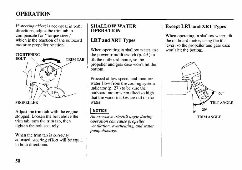
If steering effort is not equal in both directions, adjust the trim tab to compensate for “torque steer,” which is the reaction of the outboard motor to propeller rotation.
TIGHTENING
PROPELLER
Adjust the trim tab with the engine stopped. Loosen the bolt above the trim tab, turn the trim tab, then tighten the bolt securely.
When the trim tab is correctly adjusted, steering effort will be equal in both directions.
SHALLOW WATER OPERATION
LRT and XRT Types
When operating in shallow water, use the power tridtilt switch (p. 49 ) to tilt the outboard motor, so the propeller and gear case won’t hit the bottom.
Proceed at low speed, and monitor water flow from the cooling system indicator (p. 27 ) to be sure the outboard motor is not tilted so high that the water intakes are out of the water.
W] An excessive trimhilt angle during operation can cause propeller ventilation, overheating, and water pump damage.
Except LRT and XRT Types
When operating in shallow water, tilt the outboard motor, using the tilt lever, so the propeller and gear case won’t hit the bottom.
0” ‘ 20”
TRIM ANGLE
50
OPERATION
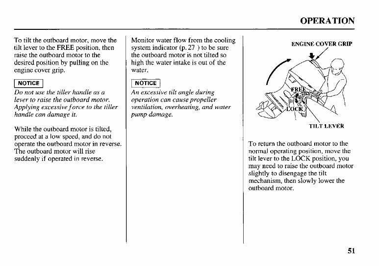
To tilt the outboard motor, move the tilt lever to the FREE position, then raise the outboard motor to the desired position by pulling on the engine cover grip.
p5E-l Do not use the tiller handle as a lever to raise the outboard motor. Applying excessive f orce to the tiller handle can damage it.
While the outboard motor is tilted, proceed at a low speed, and do not operate the outboard motor in reverse. The outboard motor will rise suddenly if operated in reverse.
Monitor water flow from the cooling system indicator (p. 27 ) to be sure the outboard motor is not tilted so high the water intake is out of the water.
An excessive tilt angle during operation can cause propeller ventilation, overheating, and water pump damage.
ENGINE COVER GRIP
TILT LEVER
To return the outboard motor to the normal operating position, move the tilt lever to the LOCK position, you may need to raise the outboard motor slightly to disengage the tilt mechanism, then slowly lower the outboard motor.
51
OPERATION
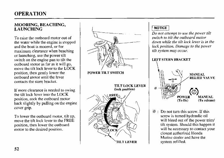
MOORING, BEACHING, LAUNCHING
To raise the outboard motor out of the water while the engine is stopped and the boat is moored, or for maximum clearance when beaching or launching, use the power tilt switch on the engine pan to tilt the outboard motor as far as it will go, move the tilt lock lever to the LOCK position, then gently lower the outboard motor until the lever contacts the stern bracket.
If more clearance is needed to swing the tilt lock lever into the LOCK position, rock the outboard motor back slightly by pulling on the engine cover grip.
To lower the outboard motor, tilt up, move the tilt lock lever to the FREE position, then lower the outboard motor to the desired position.
POWER TILT SWITCH
TILT LOCK LEVER (lock position)
/
‘TILT LEVER
Do not attempt to use the power tilt switch to tilt the outboard motor down while the tilt lock lever is in the lock position. Damage to the power tilt system may occur.
LEFT STERN BRACKET
% : Do not turn this screw. If this screw is turned hydraulic oil will bleed out of the power trim/ tilt system. Should this happen it will be necessary to contact your closest authorized Honda Marine dealer and have the system refilled.
52
OPERATION
The outboard motor can also be tilted manually after opening the manual relief valve. This feature enables the outboard motor to be tilted when no battery is connected.
For manual tilting, use a screwdriver to turn the valve counterclockwise 1 or 2 turns. Close the valve firmly after positioning the engine.
Be sure the valve is closed before operating the outboard motor. If the valve is not closed, the outboard motor will tilt up when operated in reverse.
53
SERVICING YOUR OUTBOARD MOTOR
THE IMPORTANCE OF MAINTENANCE
Good maintenance is essential for safe, economical, and trouble-free operation. It will also help reduce air pollution.
Improperly maintaining this outboard motor, or failure to correct a problem before operation, can cause a malfunction in which you could be seriously hurt or killed.
Always follow the inspection and maintenance recommendations and schedules in this owner‘s manual.
To help you properly care for your outboard motor, the following pages include a maintenance schedule, routine inspection procedures, and simple maintenance procedures using basic hand tools. Other service tasks that are more difficult, or require special tools, are best handled by professionals and are normally performed by a Honda technician or other qualified mechanic.
The maintenance schedule applies to normal operating conditions. If you operate your outboard motor under unusual conditions, consult an authorized Honda marine dealer for recommendations applicable to your individual needs and use.
Remember that your authorized Honda marine dealer knows your outboard motor best and is fully equipped to maintain and repair it.
To ensure the best quality and reliability, use only new, genuine Honda parts or their equivalents for repair and replacement.
Maintenance, replacement, or repair of the emission control devices and systems may be performed by any marine engine repair establishment or individual, using parts that are “certified” to EPA standards.
54
SERVICING YOUR OUTBOARD MOTOR
MAINTENANCE SAFETY
Some of the most important safety precautions follow. However, we cannot warn you of every conceivable hazard that can arise in performing maintenance. Only you can decide whether or not you should perform a given task.
Failure to properly follow maintenance instructions and precautions can cause you to be seriously hurt or killed.
Always follow the procedures and precautions in the owner's manual.
Safety Precautions
0 Make sure the engine is off before you begin any maintenance or repairs. This will eliminate several potential hazards:
- Carbon monoxide poisoning from engine exhaust. Be sure there is adequate ventilation whenever you operate the engine.
-Burns from hot parts. Let the engine and exhaust system cool before touching.
-Injury from moving parts. Do not run the engine unless instructed to do so.
Read the instructions before you begin, and make sure you have the tools and skills required.
To reduce the possibility of fire or explosion, be careful when working around gasoline. Use only a nonflammable solvent, not gasoline, to clean parts. Keep cigarettes, sparks, and flames away from all fuel-related parts.
0 Wear gloves when handling the propeller to protect your hands from sharp edges.
55
SERVICING YOUR OUTBOARD MOTOR
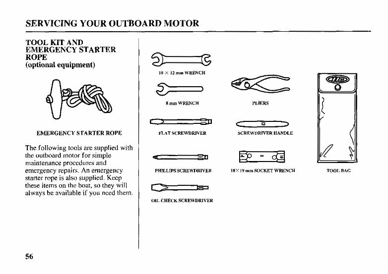
TOOL KIT AND EMERGENCY STARTER ROPE (optional equipment)
EMERGENCY STARTER ROPE
The following tools are supplied with the outboard motor for simple maintenance procedures and emergency repairs. An emergency starter rope is also supplied. Keep these items on the boat, so they will
10 X 12 mm WRENCH
8 mm WRENCH
r, FLAT SCREWDRIVER -
PHILLIPS SCREWDRIVER - OIL CHECK SCREWDRIVER
PLIERS
C 1> n
SCREWDRIVER HANDLE
18X 19 mm SOCKET WRENCH TOOL BAG
56
SERVICING YOUR OUTBOARD MOTOR
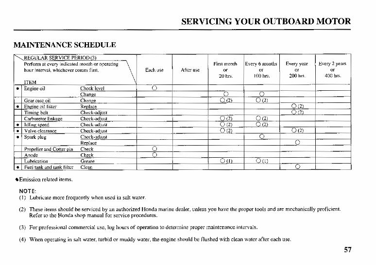
MAINTENANCE SCHEDULE
hour interval, whichever comes first. Every year
or 200 hrs.
0 ( 2 ) 0 ( 2 )
0 (2)
n
0
Every 2 years or
400 hrs.
Emission related items.
NOTE: ( 1 ) Lubricate more frequently when used in salt water.
(2) These items should be serviced by an authorized Honda marine dealer, unless you have the proper tools and are mechanically proficient. Refer to the Honda shop manual for service procedures.
(3) For professional commercial use, log hours of operation to determine proper maintenance intervals.
(4) When operating in salt water, turbid or muddy water, the engine should be flushed with clean water after each use.
57
SERVICING YOUR OUTBOARD MOTOR
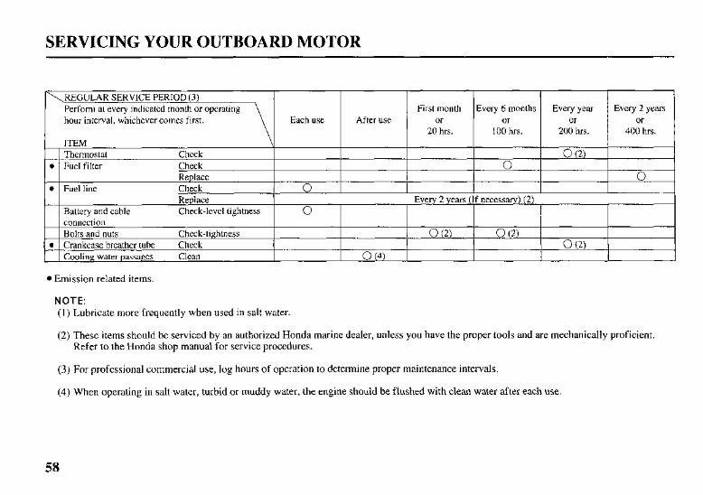
hour interval, whichever comes first.
Emission related items.
NOTE: (1) Lubricate more frequently when used in salt water.
(2) These items should be serviced by an authorized Honda marine dealer, unless you have the proper tools and are mechanically proficient. Refer to the Honda shop manual for service procedures.
( 3 ) For professional commercial use, log hours of operation to determine proper maintenance intervals.
(4) When operating in salt water, turbid or muddy water, the engine should be flushed with clean water after each use.
SERVICING YOUR OUTBOARD MOTOR
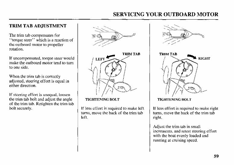
TRIM TAB ADJUSTMENT
The trim tab compensates for “torque steer” which is a reaction of the outboard motor to propeller rotation.
If uncompensated, torque steer would make the outboard motor tend to turn to one side.
When the trim tab is correctly adjusted, steering effort is equal in either direction.
If steering effort is unequal, loosen the trim tab bolt and adjust the angle of the trim tab. Retighten the trim tab bolt securely.
TIGHTENING BOLT
If less effort is required to make left turns, move the back of the trim tab left.
TIGHTENING BOLT
If less effort is required to make right turns, move the back of the trim tab right.
Adjust the trim tab in small increments, and retest steering effort with the boat evenly loaded and running at cruising speed.
59
SERVICING YOUR OUTBOARD MOTOR
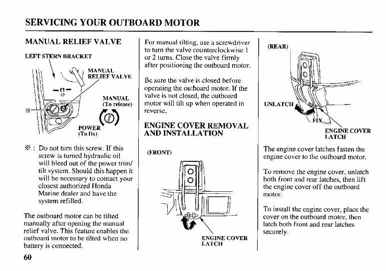
MANUAL RELIEF VALVE
LEFT STERN BRACKET
I I l l , \ 6'~ I MANUAL
(To fix)
% : Do not turn this screw. If this screw is turned hydraulic oil will bleed out of the power trim/ tilt system. Should this happen it will be necessary to contact your closest authorized Honda Marine dealer and have the system refilled.
The outboard motor can be tilted manually after opening the manual relief valve. This feature enables the outboard motor to be tilted when no battery is connected.
60
For manual tilting, use a screwdriver to turn the valve counterclockwise 1 or 2 turns. Close the valve firmly after positioning the outboard motor.
Be sure the valve is closed before operating the outboard motor. If the valve is not closed, the outboard motor will tilt up when operated in reverse.
ENGINE COVER REMOVAL AND INSTALLATION
(FRONT)
ENGINE COVER LATCH
E N G I ~ E COVER LATCH
The engine cover latches fasten the engine cover to the outboard motor.
To remove the engine cover, unlatch both front and rear latches, then lift the engine cover off the outboard motor.
To install the engine cover, place the cover on the outboard motor, then latch both front and rear latches securely.
SERVICING YOUR OUTBOARD MOTOR
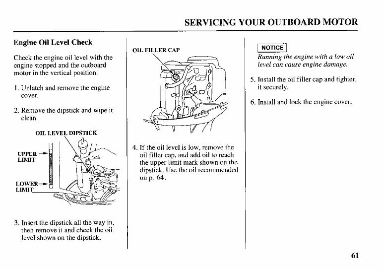
Engine Oil Level Check
Check the engine oil level with the engine stopped and the outboard motor in the vertical position.
1. Unlatch and remove the engine cover.
2. Remove the dipstick and wipe it clean.
OIL LEVEL DIPSTICK
3. Insert the dipstick all the way in, then remove it and check the oil level shown on the dipstick.
OIL FILLER CAP
4. If the oil level is low, remove the oil filler cap, and add oil to reach the upper limit mark shown on the dipstick. Use the oil recommended on p. 64.
p i 5 E - l Running the engine with a low oil level can cause engine damage.
5. Install the oil filler cap and tighten it securely.
6. Install and lock the engine cover.
61
SERVICING YOUR OUTBOARD MOTOR
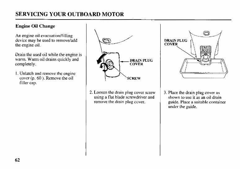
Engine Oil Change
An engine oil evacuatiodfilling device may be used to remove/add the engine oil.
Drain the used oil while the engine is warm. Warm oil drains quickly and completely.
1 . Unlatch and remove the engine cover (p. 60 ). Remove the oil filler cap.
COVER
SCREW
2. Loosen the drain plug cover screw using a flat blade screwdriver and remove the drain plug cover.
DRAIN PLUG w COVE
3. Place the drain plug cover as shown to use it as an oil drain guide. Place a suitable container under the guide.
62
SERVICING YOUR OUTBOARD MOTOR
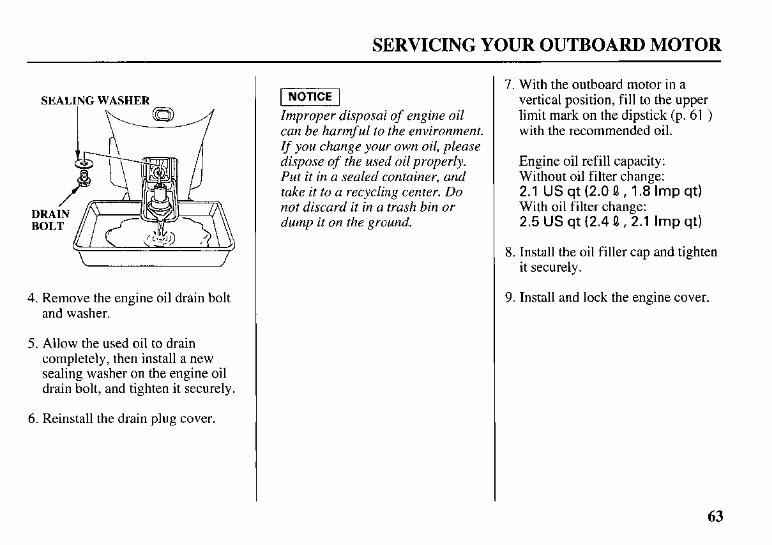
SEALING WASHER
I \w
4. Remove the engine oil drain bolt and washer.
5. Allow the used oil to drain completely, then install a new sealing washer on the engine oil drain bolt, and tighten it securely.
6. Reinstall the drain plug cover.
W I Improper disposal of engine oil can be harmful to the environment. I f you change your own oil, please dispose of the used oil properly. Put it in a sealed container, and take it to a recycling center. Do not discard it in a trash bin or dump it on the ground.
7. With the outboard motor in a vertical position, fill to the upper limit mark on the dipstick (p. 61 ) with the recommended oil.
Engine oil refill capacity: Without oil filter change: 2.1 US qt (2.0 0, 1.8 Imp qt) With oil filter change: 2.5 US qt (2.4 0, 2.1 Imp qt)
8. Install the oil filler cap and tighten it securely.
9. Install and lock the engine cover.
63
lFERVICING YOUR OUTBOARD MOTOR
Engine Oil Recommendations
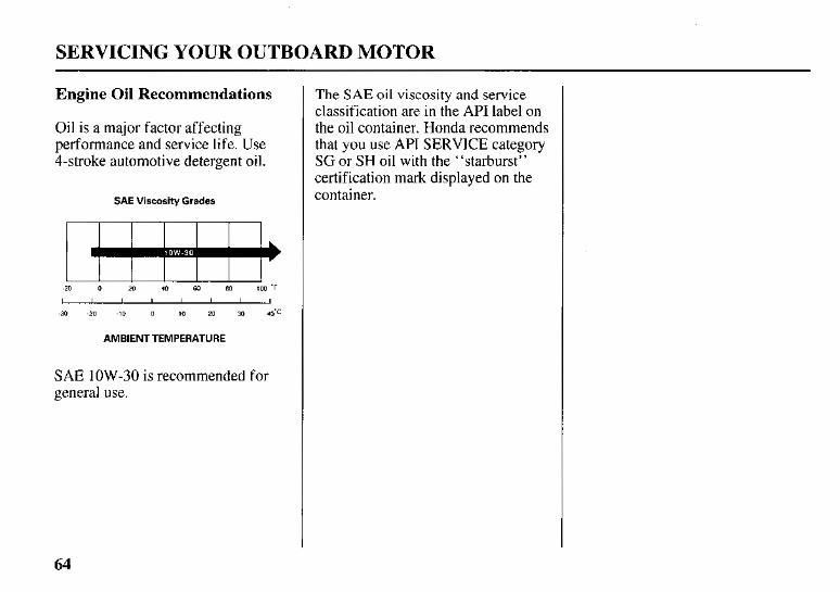
Oil is a major factor affecting performance and service life. Use 4-stroke automotive detergent oil.
SAE Viscosity Grades
-20 0 20 40 KO 80 100 ’F
I I I I I I I I
-30 -20 -10 0 10 20 30 40’c
AMBIENT TEMPERATURE
SAE 1OW-30 is recommended for general use.
The SAE oil viscosity and service classification are in the API label on the oil container. Honda recommends that you use API SERVICE category SG or SH oil with the “starburst” certification mark displayed on the container.
64
SERVICING YOUR OUTBOARD MOTOR
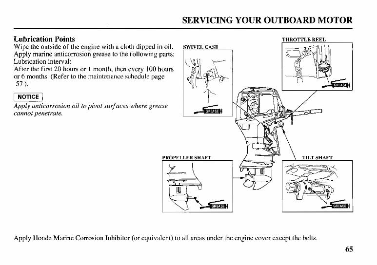
Lubrication Points Wipe the outside of the engine with a cloth dipped in oil. Apply marine anticorrosion grease to the following parts: Lubrication interval: After the first 20 hours or 1 month, then every 100 hours or 6 months. (Refer to the maintenance schedule page 57 ).
Apply anticorrosion oil to pivot surfaces where grease cannot penetrate.
THROTTLE REEL
\ TILT SHAFT
Apply Honda Marine Corrosion Inhibitor (or equivalent) to all areas under the engine cover except the belts.
65
SERVICING YOUR OUTBOARD MOTOR
Spark Plug Service
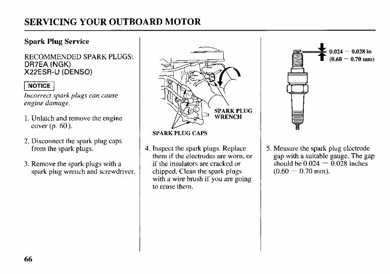
RECOMMENDED SPARK PLUGS: DR7EA (NGK) X22ESR-U (DENSO)
piq Incorrect spark plugs can cause engine damage.
1. Unlatch and remove the engine cover (p. 60).
2. Disconnect the spark plug caps from the spark plugs.
3. Remove the spark plugs with a spark plug wrench and screwdriver.
SPARK PLUG
SPARK PLUG CAPS
4. Inspect the spark plugs. Replace them if the electrodes are worn, or if the insulators are cracked or chipped. Clean the spark plugs with a wire brush if you are going to reuse them.
0.024 (0.60
- 0.028 in 0.70 mm)
5. Measure the spark plug electrode gap with a suitable gauge. The gap should be 0.024 - 0.028 inches (0.60 - 0.70 mm).
66
SERVICING YOUR OUTBOARD MOTOR
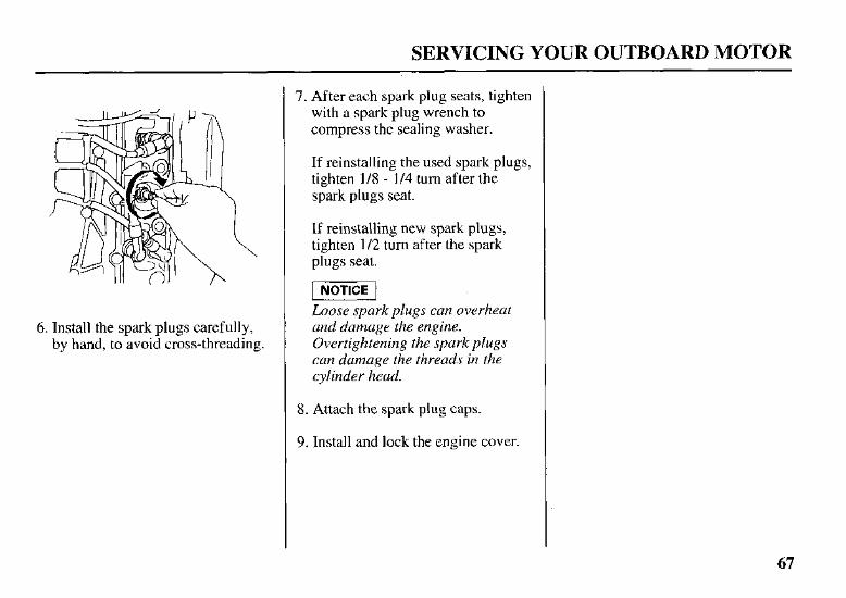
6. Install the spark plugs carefully, by hand, to avoid cross-threading.
7. After each spark plug seats, tighten with a spark plug wrench to compress the sealing washer.
If reinstalling the used spark plugs, tighten 1/8 - 1/4 turn after the spark plugs seat.
If reinstalling new spark plugs, tighten 1/2 turn after the spark plugs seat.
-1 Loose spark plugs can overheat and damage the engine. Overtightening the spark plugs can damage the threads in the cylinder head.
8. Attach the spark plug caps.
9. Install and lock the engine cover.
67
SERVICING YOUR OUTBOARD MOTOR
REFUELING
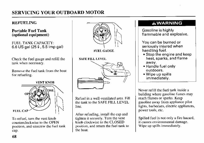
PorUable Fuel Tank (optional equipment)
FUEL TANK CAPACITY: 6.6 US gal (25 0, 5.5 Imp gal)
Check the fuel gauge and refill the tank when necessary.
Remove the fuel tank from the boat for refueling.
VENT KNOB
To refuel, turn the vent knob counterclockwise to the OPEN position, and unscrew the fuel tank cap.
68
FUEL GAUGE
SAFE FILL LEVEL
Refuel in a well-ventilated area. Fill the tank to the SAFE FILL LEVEL line.
After refueling, install the cap and tighten it securely. Turn the vent knob clockwise to the CLOSED position, and return the fuel tank to the boat.
Gasoline is highly flammable and explosive.
You can be burned or seriously injured when handling fuel.
Stop the engine and keep heat, sparks, and flame away. Handle fuel only outdoors. Wipe up spills immediately.
Never refill the fuel tank inside a building where gasoline fumes may reach flames or sparks. Keep gasoline away from appliance pilot lights, barbecues, electric appliances, power tools, etc.
Spilled fuel is not only a fire hazard, it causes environmental damage. Wipe up spills immediately.
SERVICING YOUR OUTBOARD MOTOR
FUEL RECOMMENDATIONS
Use unleaded gasoline with a pump octane rating of 86 or higher.
These outboard motors are certified to operate on unleaded gasoline. Unleaded gasoline produces fewer engine and spark plug deposits and extends exhaust system life.
Never use stale or contaminated gasoline or an oil/gasoline mixture. Avoid getting dirt or water in the fuel tank.
Occasionally you may hear a light “spark knock” or “pinging” (metallic rapping noise) while operating under heavy loads. This is no cause for concern.
If spark knock or pinging occurs at a steady engine speed, under normal load, change brands of gasoline. If spark knock or pinging persists, see an authorized Honda marine dealer.
-1 Running the engine with persistent spark knock or pinging can cause engine damage.
Running the engine with persistent spark knock or pinging is misuse, and the Distributor’s Limited Warranty does not cover parts damaged by misuse.
69
SERVICING YOUR OUTBOARD MOTOR
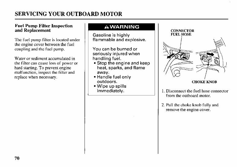
Fuel Pump Filter Inspection and Replacement
The fuel pump filter is located under the engine cover between the fuel coupling and the fuel pump.
Water or sediment accumulated in the filter can cause loss of power or hard starting. To prevent engine malfunction, inspect the filter and replace when necessary.
Gasoline is highly flammable and explosive.
You can be burned or seriously injured when handling fuel.
Stop the engine and keep heat, sparks, and flame away. Handle fuel only outdoors. Wipe up spills immediately.
CONNECTOR FUEL HOSE
CHOKE KNOB
1. Disconnect the fuel hose connector from the outboard motor.
2. Pull the choke knob fully and remove the engine cover.
70
SERVICING YOUR OUTBOARD MOTOR
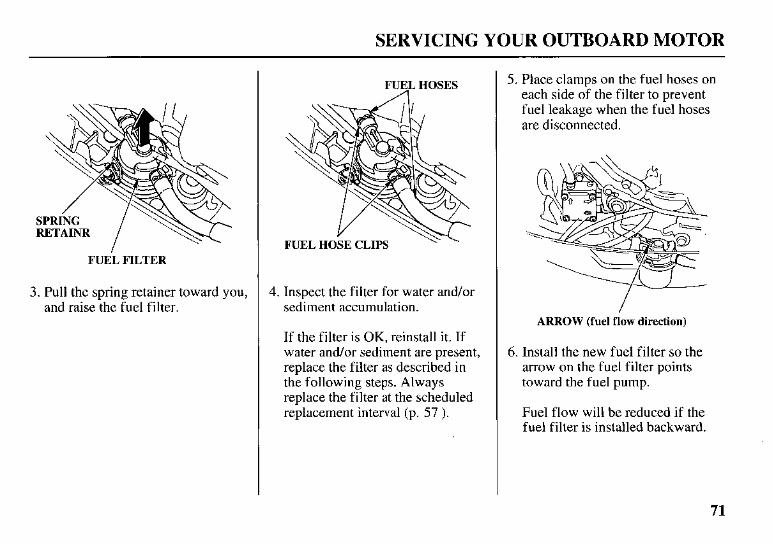
FUEL FILTER
3. Pull the spring retainer toward you, and raise the fuel filter.
FUEL HOSES
4. Inspect the filter for water and/or sediment accumulation.
If the filter is OK, reinstall it. If water and/or sediment are present, replace the filter as described in the following steps. Always replace the filter at the scheduled replacement interval (p. 57 ).
5. Place clamps on the fuel hoses on each side of the filter to prevent fuel leakage when the fuel hoses are disconnected.
ARROW (fuel flow direction)
6. Install the new fuel filter so the arrow on the fuel filter points toward the fuel pump.
Fuel flow will be reduced if the fuel filter is installed backward.
71
SERVICING YOUR OUTBOARD MOTOR
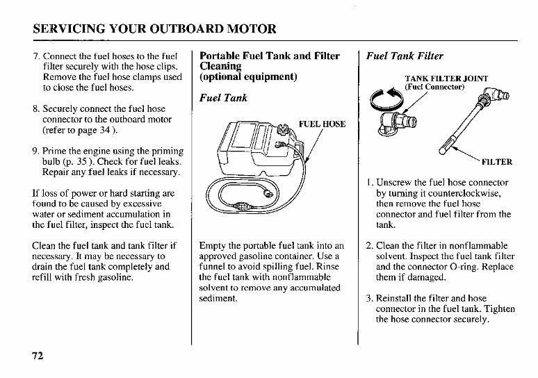
7. Connect the fuel hoses to the fuel filter securely with the hose clips. Remove the fuel hose clamps used to close the fuel hoses.
8. Securely connect the fuel hose connector to the outboard motor (refer to page 34 ).
9. Prime the engine using the priming bulb (p. 35 ). Check for fuel leaks. Repair any fuel leaks if necessary.
If loss of power or hard starting are found to be caused by excessive water or sediment accumulation in the fuel filter, inspect the fuel tank.
Clean the fuel tank and tank filter if necessary. It may be necessary to drain the fuel tank completely and refill with fresh gasoline.
Portable Fuel Tank and Filter Cleaning (optional equipment)
Fuel Tank
Empty the portable fuel tank into an approved gasoline container. Use a funnel to avoid spilling fuel. Rinse the fuel tank with nonflammable solvent to remove any accumulated sediment.
Fuel Tank Filter
TANK FILTER JOINT
' FILTER
1. Unscrew the fuel hose connector by turning it counterclockwise, then remove the fuel hose connector and fuel filter from the tank.
2. Clean the filter in nonflammable solvent. Inspect the fuel tank filter and the connector O-ring. Replace them if damaged.
3. Reinstall the filter and hose connector in the fuel tank. Tighten the hose connector securely.
72
SERVICING YOUR OUTBOARD MOTOR
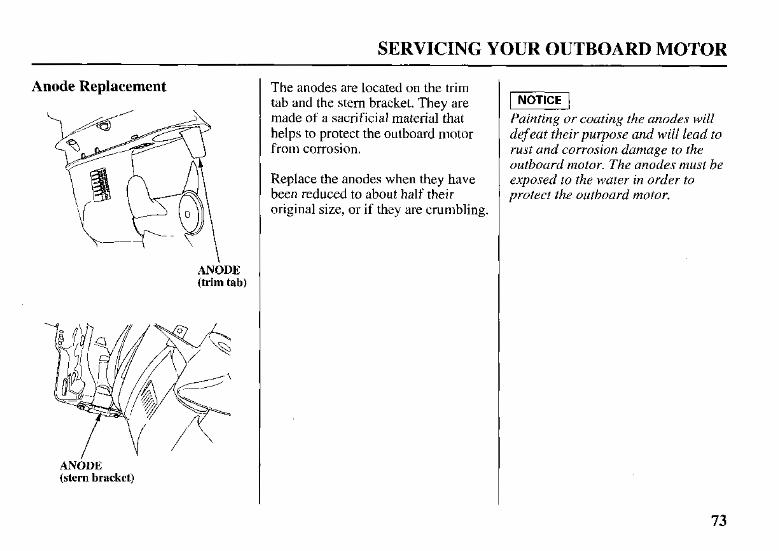
Anode Replacement
ANODE (trim tab)
ANODE (stern bracket)
The anodes are located on the trim tab and the stern bracket. They are made of a sacrificial material that helps to protect the outboard motor from corrosion.
Replace the anodes when they have been reduced to about half their original size, or if they are crumbling.
Painting or coating the anodes will defeat their purpose and will lead to rust and corrosion damage to the outboard motor. The anodes must be exposed to the water in order to protect the outboard motor.
73
SERVICING YOUR OUTBOARD MOTOR
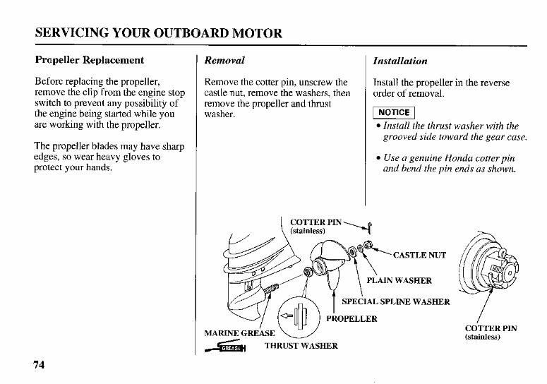
Propeller Replacement
Before replacing the propeller, remove the clip from the engine stop switch to prevent any possibility of the engine being started while you are working with the propeller.
The propeller blades may have sharp edges, so wear heavy gloves to protect your hands.
Removal
Remove the cotter pin, unscrew the castle nut, remove the washers, then remove the propeller and thrust washer.
Installation
Install the propeller in the reverse order of removal.
pmq Install the thrust washer with the grooved side toward the gear case.
Use a genuine Honda cotter pin and bend the pin ends as shown.
\ (stainless) COTTER PIN
CASTLE NUT
AIN WASHER
PROPELLER
MARINE GREASE 6 THRUST WASHER
COTTER PIN (stainless)
74
STORAGE
STORAGE PREPARATION
Proper storage preparation is essential for keeping your outboard motor troublefree and looking good. The following steps will help to keep rust and corrosion from impairing your outboard motor’s function and appearance, and will make the engine easier to start when you use the outboard motor again.
Cleaning and Flushing
Thoroughly clean and flush the outboard motor with fresh water after operation in dirty water or salt water.
Touch up any damaged paint, and coat areas that may rust with a light film of oil. Lubricate controls with a silicone spray lubricant.
Cleaning
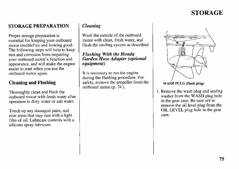
Wash the outside of the outboard motor with clean, fresh water, and flush the cooling system as described.
Flushing With the Honda Garden Hose Adapter (optional equipment)
It is necessary to run the engine during the flushing procedure. For safety, remove the propeller from the outboard motor (p. 74 ).
WASH PLUG (flush plug)
1. Remove the wash plug and sealing washer from the WASH plug hole in the gear case. Be sure not to remove the oil level plug from the OIL LEVEL plug hole in the gear case.
75
STORAGE
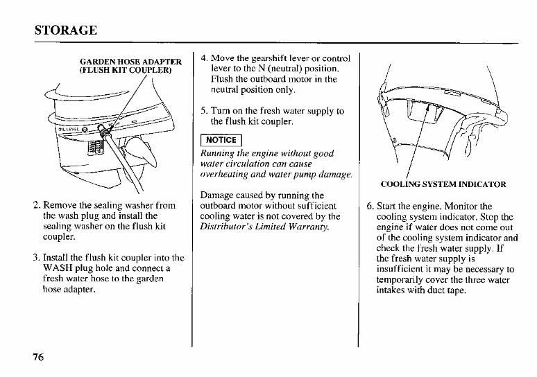
GARDEN HOSE ADAPTER (FLUSH KIT COUPLER)
2. Remove the sealing washer from the wash plug and install the sealing washer on the flush lut coupler.
3. Install the flush kit coupler into the WASH plug hole and connect a fresh water hose to the garden hose adapter.
4. Move the gearshift lever or control lever to the N (neutral) position. Flush the outboard motor in the neutral position only.
5. Turn on the fresh water supply to the flush kit coupler.
I NOTICE I Running the engine without good water circulation can cause overheating and water pump damage.
Damage caused by running the outboard motor without sufficient cooling water is not covered by the Distributor’s Limited Warranty.
I \
COOLING SYSTEM INDICATOR
6. Start the engine. Monitor the cooling system indicator. Stop the engine if water does not come out of the cooling system indicator and check the fresh water supply. If the fresh water supply is insufficient it may be necessary to temporarily cover the three water intakes with duct tape.
76
STORAGE
WATER INTAKES
WATER INTAKES
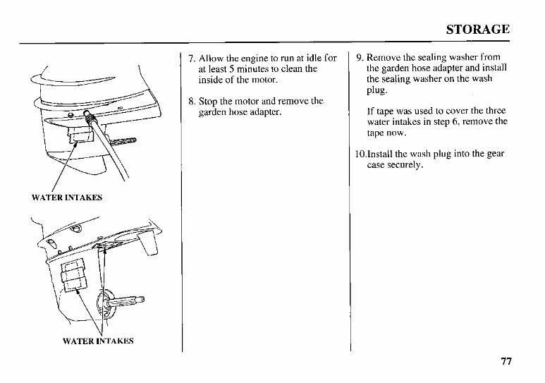
7. Allow the engine to run at idle for at least 5 minutes to clean the inside of the motor.
8. Stop the motor and remove the garden hose adapter.
9. Remove the sealing washer from the garden hose adapter and install the sealing washer on the wash Plug.
If tape was used to cover the three water intakes in step 6, remove the tape now.
1O.Install the wash plug into the gear case securely.
77
STORAGE
Fuel
Gasoline will oxidize and deteriorate in storage. Old gasoline will cause hard starting, and it leaves gum deposits that clog the fuel system. If the gasoline in your fuel tank and carburetor deteriorates during storage, you may need to have the carburetor and other fuel system components serviced or replaced.
The length of time that gasoline can be left in your fuel tank and carburetor without causing functional problems will vary with such factors as gasoline blend, your storage temperatures, and whether the fuel tank is partially or completely filled. The air in a partially filled fuel tank promotes fuel deterioration. Very warm storage temperatures accelerate fuel deterioration. Fuel deterioration problems may occur within a few months, or even less if the gasoline was not fresh when you filled the fuel tank.
78
The Distributor’s Limited Warranty does not cover fuel system damage or engine performance problems resulting from neglected storage preparation.
You can avoid fuel deterioration problems by draining the fuel tank and carburetors.
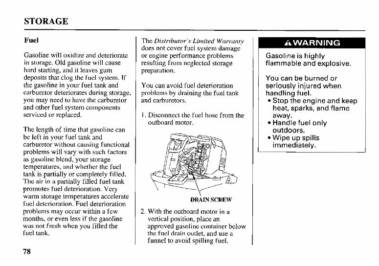
1 . Disconnect the fuel hose from the outboard motor.
DRAIN SCREW
2. With the outboard motor in a vertical position, place an approved gasoline container below the fuel drain outlet, and use a funnel to avoid spilling fuel.
Gasoline is highly flammable and explosive.
You can be burned or seriously injured when handling fuel.
Stop the engine and keep heat, sparks, and flame away. Handle fuel only outdoors. Wipe up spills immediately.
STORAGE
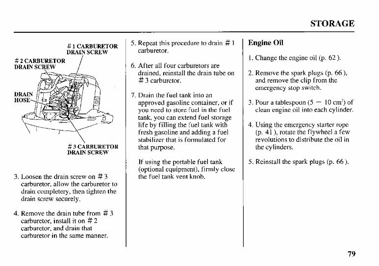
# 1 CARBURETOR DRAIN SCREW
# 2 CARBURETOR DRAIN SCREW
# 3 CARBURETOR DRAIN SCREW
3. Loosen the drain screw on # 3 carburetor, allow the carburetor to drain completery, then tighten the drain screw securely.
4. Remove the drain tube from # 3 carburetor, install it on # 2 carburetor, and drain that carburetor in the same manner.
5. Repeat this procedure to drain # 1 carburetor.
6. After all four carburetors are drained, reinstall the drain tube on # 3 carburetor.
7. Drain the fuel tank into an approved gasoline container, or if you need to store fuel in the fuel tank, you can extend fuel storage life by filling the fuel tank with fresh gasoline and adding a fuel stabilizer that is formulated for that purpose.
If using the portable fuel tank (optional equipment), firmly close the fuel tank vent knob.
Engine Oil
1. Change the engine oil (p. 62 ).
2. Remove the spark plugs (p. 66 ), and remove the clip from the emergency stop switch.
3. Pour a tablespoon (5 - I O cm’) of clean engine oil into each cylinder.
4. Using the emergency starter rope (p. 41 ), rotate the flywheel a few revolutions to distribute the oil in the cylinders.
5. Reinstall the spark plugs (p. 66 ).
79
STORAGE
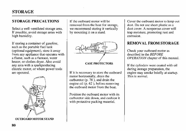
STORAGE PRECAUTIONS
Select a well-ventilated storage area. If possible, avoid storage areas with high humidity.
If storing a container of gasoline, such as the portable fuel tank (optional equipment), store i t away from any appliance that operates with a flame, such as a furnace, water heater, or clothes dryer. Also avoid any area with a sparkproducing electric motor, or where power tools are operated.
OUTBOARD MOTOR STAND
If the outboard motor will be removed from the boat for storage, we recommend storing it vertically by mounting it on a stand.
/ CASE PROTECTORS
If it is necessary to store the outboard motor horizontally, drain the carburetor (p. 78 ), and drain the engine oil (p. 62 ), before removing the outboard motor from the boat.
Position the outboard motor with its carburetor side down, and cushion it with protective packing material.
Cover the outboard motor to keep out dust. Do not use sheet plastic as a dust cover. A nonporous cover will trap moisture, promoting rust and corrosion.
REMOVAL FROM STORAGE
Check your outboard motor as described in the BEFORE OPERATION chapter of this manual.
If the cylinders were coated with oil during storage preparation, the engine may smoke briefly at startup. This is normal.
$0
TRANSPORTING
WITH OUTBOARD MOTOR INSTALLED ON BOAT
When trailering a boat with the outboard motor attached, leave the engine in the normal running position, if possible.
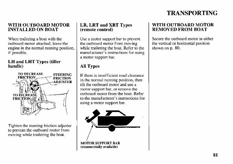
LH and LHT Types (tiller handle)
TO DECREASE STEERING FRICTION
Tighten the steering friction adjuster to prevent the outboard motor from moving while trailering the boat.
LR, LRT and XRT Types (remote control)
Use a motor support bar to prevent the outboard motor from moving while trailering the boat. Refer to the manufacturer’s instructions for using a motor support bar.
All Types
If there is insufficient road clearance in the normal running position, then tilt the outboard motor and use a motor support bar, or remove the outboard motor from the boat. Refer to the manufacturer’s instructions for using a motor support bar.
MOTOR SUPPORT BAR (commercially available)
WITH OUTBOARD MOTOR REMOVED FROM BOAT
Secure the outboard motor in either the vertical or horizontal position shown on p. 80.
81
TAKING CARE OF UNEXPECTED PROBLEMS
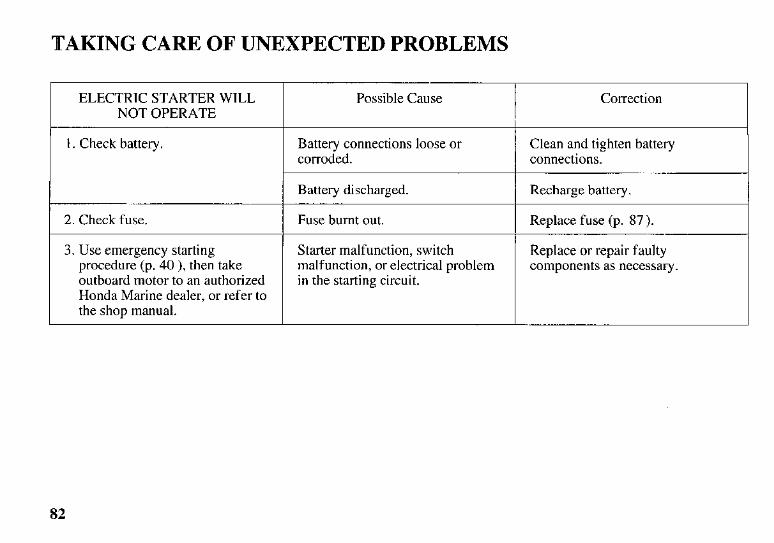
ELECTRIC STARTER WILL NOT OPERATE
1 . Check battery
2. Check fuse.
3. Use emergency starting procedure (p. 40 ), then take outboard motor to an authorized Honda Marine dealer, or refer to the shop manual.
Possible Cause
Battery connections loose or corroded.
Battery discharged.
Fuse burnt out.
Starter malfunction, switch malfunction, or electrical problem in the starting circuit.
Correction
Clean and tighten battery connections.
Recharge battery.
Replace fuse (p. 87).
Replace or repair faulty components as necessary.
82
TAKING CARE OF UNEXPECTED PROBLEMS
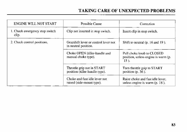
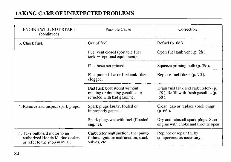
ENGINE WILL NOT START
1. Check emergency stop switch clip.
2. Check control positions.
Possible Cause
Clip not inserted in stop switch.
Gearshift lever or control lever not in neutral position.
Choke OPEN (tiller-handle and manual choke type).
Throttle grip not in START position (tiller-handle type).
~~
Choke and fast idle lever not raised (side-mount type).
Correction
Insert clip in stop switch.
Shift to neutral (p. 16 and 19 ).
Pull choke knob to CLOSED position, unless engine is warm (p. 15 ).
Turn throttle grip to START position (p. 36 ).
Raise choke and fast idle lever, unless engine is warm (p. 18 ).
83
TAKING CARE OF UNEXPECTED PROBLEMS
ENGINE WILL NOT START Possible Cause (continued)
3. Check fuel. Out of fuel.
Fuel vent closed (portable fuel tank - optional equipment).
I Fuel hose not primed.
Fuel pump filter or fuel tank filter clogged.
Bad fuel; boat stored without treating or draining gasoline, or refueled with bad gasoline.
4. Remove and inspect spark plugs.
Spark plugs wet with fuel (flooded engine).
5. Take outboard motor to an
valves, etc. or refer to the shop manual. failure, ignition malfunction, stuck authorized Honda Marine dealer, Carburetor malfunction, fuel pump
Correction
Refuel (p. 68 ).
Open fuel tank vent (p. 28 ).
Squeeze priming bulb (p. 29 ).
Replace fuel filters (p. 70 ).
Drain fuel tank and carburetors (p. 78 ). Refill with fresh gasoline (p. 68 ).
Clean, gap or replace spark plugs (P. 66 1. Dry and reinstall spark plugs. Start engine with choke and throttle open.
Replace or repair faulty components as necessary.
84
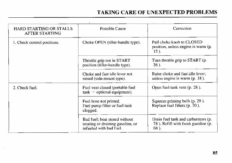
TAKING CARE OF UNEXPECTED PROBLEMS
HARD STARTING OR STALLS Possible Cause AFTER STARTING
1 . Check control positions. Choke OPEN (tiller-handle type).
Throttle grip not in START position (tiller-handle type).
Choke and fast idle lever not raised (side-mount type).
2. Check fuel. Fuel vent closed (portable fuel tank - optional equipment).
Fuel hose not primed. Fuel pump filter or fuel tank clogged.
Bad fuel; boat stored without treating or draining gasoline, or refueled with bad fuel.
Correction
Pull choke knob to CLOSED position, unless engine is warm (p. 15 ).
Turn throttle grip to START (p. 36 ).
Raise choke and fast idle lever, unless engine is warm (p. 18 ).
Open fuel tank vent (p. 28 ).
Squeeze priming bulb (p. 29 ). Replace fuel filters (p. 70).
Drain fuel tank and carburetors (p. 78 ). Refill with fresh gasoline (p. 68 ).
85
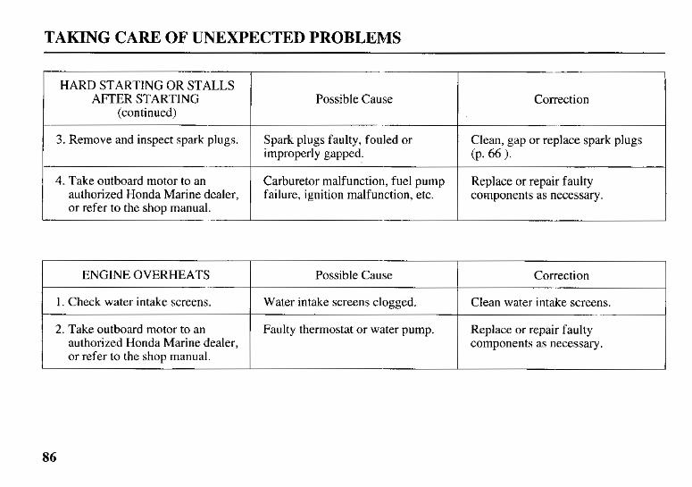
TAKING CARE OF UNEXPECTED PROBLEMS
HARD STARTING OR STALLS AFTER STARTING
(continued)
3. Remove and inspect spark plugs.
4. Take outboard motor to an authorized Honda Marine dealer, or refer to the shop manual.
Possible Cause
Spark plugs faulty, fouled or improperly gapped.
Carburetor malfunction, fuel pump failure, ignition malfunction, etc.
Correction
Clean, gap or replace spark plugs (P. 66 1. Replace or repair faulty components as necessary.
ENGKNE OVERHEATS
Clean water intake screens. Water intake screens clogged. 1. Check water intake screens.
Correction Possible Cause
2. Take outboard motor to an authorized Honda Marine dealer, or refer to the shop manual.
Faulty thermostat or water pump. Replace or repair faulty components as necessary.
86
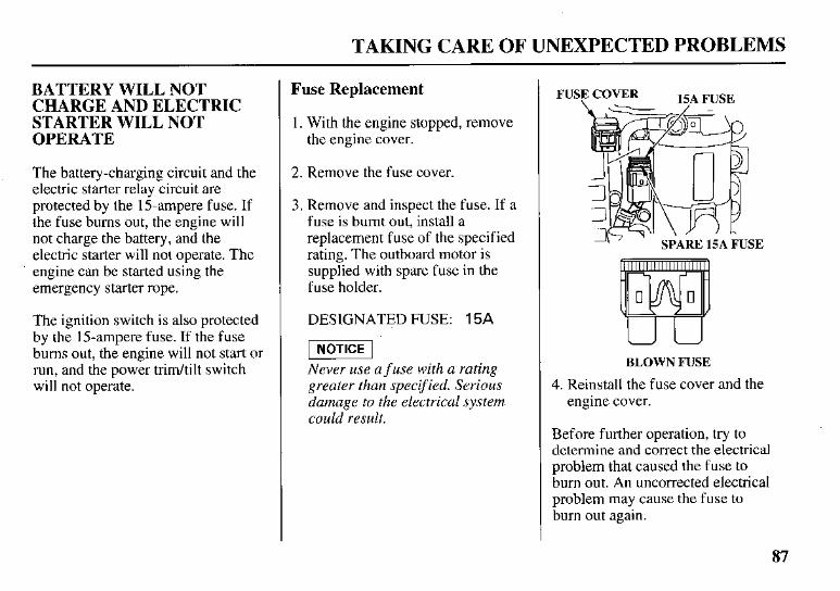
TAKING CARE OF UNEXPECTED PROBLEMS
BATTERY WILL NOT CHARGE AND ELECTRIC STARTER WILL NOT OPERATE
The battery-charging circuit and the electric starter relay circuit are protected by the 15-ampere fuse. If the fuse burns out, the engine will not charge the battery, and the electric starter will not operate. The engine can be started using the emergency starter rope.
The ignition switch is also protected by the 15-ampere fuse. If the fuse bums out, the engine will not start or run, and the power tridtilt switch will not operate.
Fuse Replacement
1. With the engine stopped, remove the engine cover.
2. Remove the fuse cover.
3 . Remove and inspect the fuse. If a fuse is burnt out, install a replacement fuse of the specified rating. The outboard motor is supplied with spare fuse in the fuse holder.
DESIGNATED FUSE: 15A
-1 Never use a f use with a rating greater than specified. Serious damage to the electrical system could result.
F1
BLOWN FUSE
4. Reinstall the fuse cover and the engine cover.
Before further operation, try to determine and correct the electrical problem that caused the fuse to bum out. An uncorrected electrical problem may cause the fuse to bum out again.
87
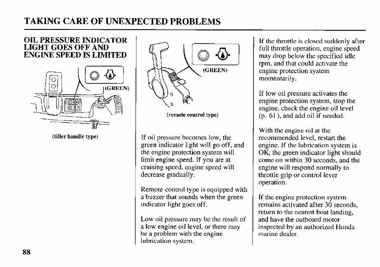
TAKING CARE OF UNEXPECTED PROBLEMS
OIL PRESSURE INDICATOR LIGHT GOES OFF AND ENGINE SPEED IS LIMITED
\ ' '
(tiller handle type)
(remote control type)
If oil pressure becomes low, the green indicator light will go off, and the engine protection system will limit engine speed. If you are at cruising speed, engine speed will decrease gradually.
Remote-control type is equipped with a buzzer that sounds when the green indicator light goes off.
Low oil pressure may be the result of a low engine oil level, or there may be a problem with the engine lubrication system.
If the throttle is closed suddenly after full throttle operation, engine speed may drop below the specified idle rpm, and that could activate the engine protection system momentarily.
If low oil pressure activates the engine protection system, stop the engine, check the engine oil level (p. 61 ), and add oil if needed.
With the engine oil at the recommended level, restart the engine. If the lubrication system is OK, the green indicator light should come on within 30 seconds, and the engine will respond normally to throttle grip or control lever operation.
If the engine protection system remains activated after 30 seconds, return to the nearest boat landing, and have the outboard motor inspected by an authorized Honda marine dealer.
88
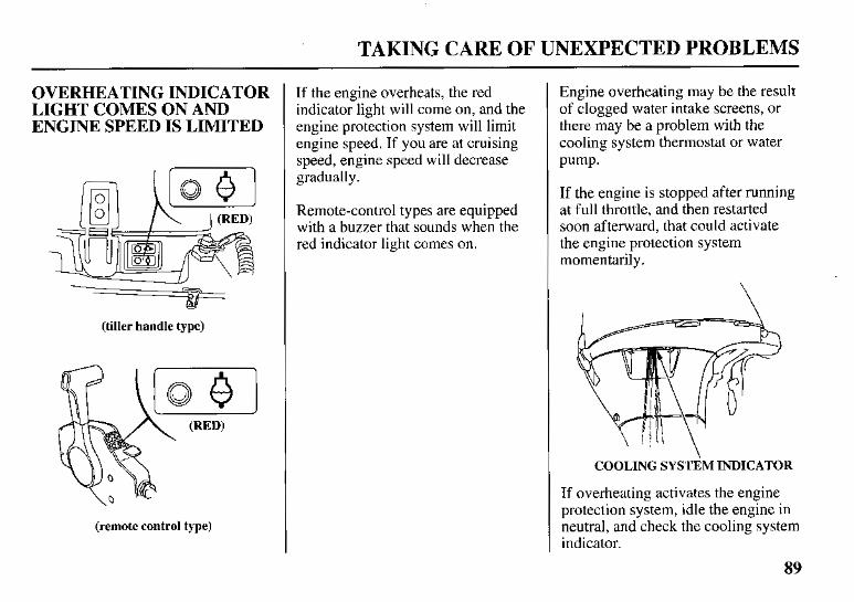
TAKING CARE OF UNEXPECTED PROBLEMS
OVERHEATING INDICATOR LIGHT COMES ON AND ENGINE SPEED IS LIMITED
Y (tiller handle type)
(remote control type)
If the engine overheats, the red indicator light will come on, and the engine protection system will limit engine speed. If you are at cruising speed, engine speed will decrease gradually.
Remote-control types are equipped with a buzzer that sounds when the red indicator light comes on.
Engine overheating may be the result of clogged water intake screens, or there may be a problem with the cooling system thermostat or water pump.
If the engine is stopped after running at full throttle, and then restarted soon afterward, that could activate the engine protection system momentarily.
COOLING SYSTEM INDICATOR
If overheating activates the engine protection system, idle the engine in neutral, and check the cooling system indicator.
89
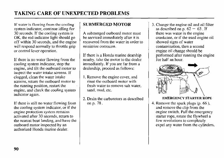
TAKING CARE OF UNEXPECTED PROBLEMS
If water is flowing from the cooling system indicator, continue idling for 30 seconds. If the cooling system is OK, the red indicator light should go off within 30 seconds, and the engine will respond normally to throttle grip or control lever operation.
If there is no water flowing from the cooling system indicator, stop the engine, and tilt the outboard motor to inspect the water intake screens. If clogged, clean the water intake screens, return the outboard motor to the running position, restart the engine, and check the cooling system indicator again.
If there is still no water flowing from the cooling system indicator, or if the engine protection system remains activated after 30 seconds, return to the nearest boat landing, and have the outboard motor inspected by an authorized Honda marine dealer.
SUBMERGED MOTOR
A submerged outboard motor must be serviced immediately after it is recovered from the water in order to minimize corrosion.
If there is a Honda marine dearship nearby, take the motor to the dealer immediately. If you are far from a dealership, proceed as follows:
1. Remove the engine cover, and rinse the outboard motor with fresh water to remove salt water, sand, mud, etc.
2. Drain the carburetors as described on p. 78.
3. Change the engine oil and oil filter as described on p. 62 - 63 . If there was water in the engine crankcase, or if the used engine oil showed signs of water contamination, then a second engine oil change should be performed after running the engine for half an hour.
EMERGENCY STARTER ROPE 4. Remove the spark plugs (p. 66 ),
and remove the clip from the engine switch. Pull the emergency starter rope, rotate the flywheel a few revolutions to completely expel any water from the cylinders.
90
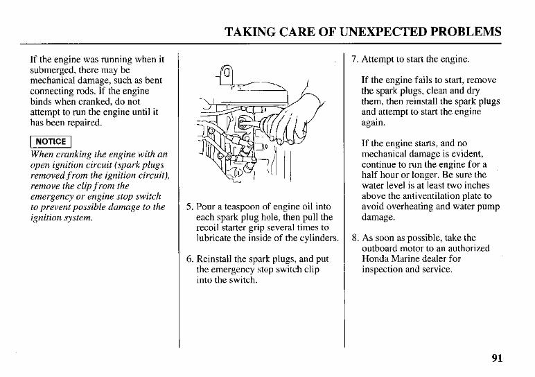
TAKING CARE OF UNEXPECTED PROBLEMS
If the engine was running when it submerged, there may be mechanical damage, such as bent connecting rods. If the engine binds when cranked, do not attempt to run the engine until it has been repaired.
-1 When cranking the engine with an open ignition circuit (spark plugs removed f rom the ignition circuit), remove the clip f rom the emergency or engine stop switch to prevent possible damage to the ignition system.
5. Pour a teaspoon of engine oil into each spark plug hole, then pull the recoil starter grip several times to lubricate the inside of the cylinders.
6. Reinstall the spark plugs, and put the emergency stop switch clip into the switch.
7. Attempt to start the engine.
If the engine fails to start, remove the spark plugs, clean and dry them, then reinstall the spark plugs and attempt to start the engine again.
If the engine starts, and no mechanical damage is evident, continue to run the engine for a half hour or longer. Be sure the water level is at least two inches above the antiventilation plate to avoid overheating and water pump damage.
8. As soon as possible, take the outboard motor to an authorized Honda Marine dealer for inspection and service.
91
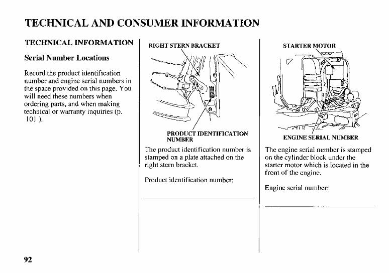
TECHNICAL AND CONSUMER INFORMATION
TECHNICAL INFORMATION
Serial Number Locations
Record the product identification number and engine serial numbers in the space provided on this page. You will need these numbers when ordering parts, and when making technical or warranty inquiries (p. 101 1.
RIGHT STERN BRACKET
PRODUCT IDENTIFICATION NUMBER
The product identification number is stamped on a plate attached on the right stem bracket.
Product identification number:
STARTER MOTOR
ENGINE SERIAL NUMBER
The engine serial number is stamped on the cylinder block under the starter motor which is located in the front of the engine.
Engine serial number:
92
TECHNICAL AND CONSUMER INFORMATION
Carburetor Modification for High Altitude Operation
At high altitude, the standard carburetor air-fuel mixture will be too rich. Performance will decrease, and fuel consumption will increase. A very rich mixture will also foul the spark plugs and cause hard starting.
High altitude performance can be improved by specific modifications to the carburetors. If you always operate your outboard motor at altitudes above 5,000 feet (1,500 meters), have an authorized Honda marine dealer perform this carburetor modification.
Even with carburetor modification, engine horsepower will decrease about 3.5% for each 1,000-foot (300- meter) increase in altitude. The effect of altitude on horsepower will be greater than this if no carburetor modification is made.
When the carburetors have been modified f or high altitude operation, the air-fuel mixture will be too lean f o r low altitude use. Operation at altitudes below 5,000 feet (1,500 meters) with modified carburetors may cause the engine to overheat and result in serious engine damage. For use at low altitudes, have an authorized Honda Marine dealer return the carburetors to original factory specifications.
93
TECHNICAL AND CONSUMER INFORMATION
Oxygenated Fuels
Some conventional gasolines are being blended with alcohol or an ether compound. These gasolines are collectively referred to as oxygenated fuels. To meet clean air standards, some areas of the United States and Canada use oxygenated fuels to help reduce emissions.
If you use an oxygenated fuel, be sure it is unleaded and meets the minimum octane rating requirement.
Before using an oxygenated fuel, try to confirm the fuel’s contents. Some states/provinces require this information to be posted on the pump.
The following are the EPA-approved percentages of oxygenates:
ETHANOL: ethyl or grain alcohol; 10% by volume.
You may use gasoline containing up to 10% ethanol by volume. Gasoline containing ethanol may be marketed under the name “Gasohol”.
MTBE: Methyl Tertiary Butyl Ether; 15% by volume.
You may use gasoline containing up to 15% MTBE by volume.
METHANOL: methyl or wood alcohol; 5% by volume.
You may use gasoline containing up to 5% methanol by volume, as long as it also contains cosolvents and corrosion inhibitors to protect the fuel system. Gasoline containing more than 5 % methanol by volume may cause starting and/or performance problems. It may also
damage metal, rubber, and plastic parts of your fuel system.
If you notice any undesirable operating symptoms, try another service station, or switch to another brand of gasoline.
Fuel system damage or performance problems resulting from the use of an oxygenated fuel containing more than the percentages of oxygenates mentioned above are not covered under warranty.
94
TECHNICAL AND CONSUMER INFORMATION
Emission Control System Information
Source of Emissions
The combustion process produces carbon monoxide, oxides of nitrogen, and hydrocarbons. Control of hydrocarbons and oxides of nitrogen is very important because, under certain conditions, they react to form photochemical smog when subjected to sunlight. Carbon monoxide does not react in the same way, but it is toxic.
Honda utilizes lean carburetor settings and other systems to reduce the emissions of carbon monoxide, oxides of nitrogen, and hydrocarbons.
The US. and California Clean Air Acts
EPA and California regulations require all manufacturers to furnish written instructions describing the operation and maintenance of emission control systems.
The following instructions and procedures must be followed in order to keep the emissions from your Honda engine within the emission standards.
Tampering and Altering
Tampering with or altering the emission control system may increase emissions beyond the legal limit. Among those acts that constitute tampering are:
Removal or alteration of any part of the intake, fuel, or exhaust systems.
Alterations that would cause the engine to operate outside its design parameters.
95
TECHNICAL AND CONSUMER INFORMATION
Problems That May Affect Emissions
If you are aware of any of the following symptoms, have your engine inspected and repaired by your servicing dealer.
0 Hard starting or stalling after starting.
0 Rough idle.
0 Misfiring or backfiring under load.
0 Afterburning (backfiring).
0 Black exhaust smoke or high fuel consumption.
Replacement Parts
The emission control systems on your Honda engine were designed, built, and certified to conform with EPA and California emission regulations. We recommend the use of genuine Honda parts whenever you have maintenance done. These original-design replacement parts are manufactured to the same standards as the original parts, so you can be confident of their performance. The use of replacement parts that are not of the original design and quality may impair the effectiveness of your emission control system.
A manufacturer of an aftermarket part assumes the responsibility that the part will not adversely affect emission performance. The manufacturer or rebuilder of the part must certify that use of the part will not result in a failure of the engine to comply with emission regulations.
Maintenance
Follow the maintenance schedule on p. 54. Remember that this schedule is based on the assumption that your machine will be used for its designed purpose. Sustained high-load operation, or use in unusual conditions, will require more frequent service.
96
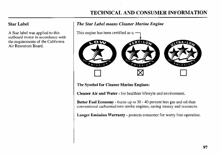
TECHNICAL AND CONSUMER INFORMATION
Star Label I The Star Label means Cleaner Marine Engine
A Star label was applied to this This engine has been certified as a: outboard motor in accordance with the requirements of the California Air Resources Board. A
0 IXI n The Symbol for Cleaner Marine Engines:
Cleaner Air and Water - for healthier lifestyle and environment.
Better Fuel Economy - bums up to 30 - 40 percent less gas and oil than conventional carbureted two-stroke engines, saving money and resources.
Longer Emission Warranty - protects consumer for worry free operation.
97
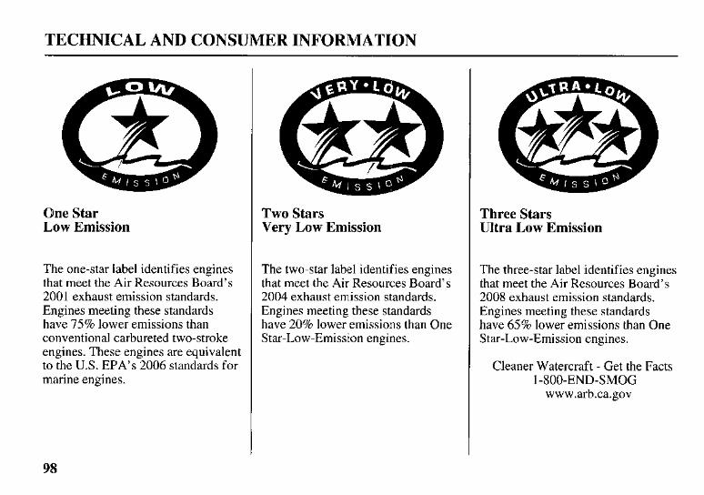
TECHNICAL AND CONSUMER INFORMATION
One Star Low Emission
The one-star label identifies engines that meet the Air Resources Board’s 2001 exhaust emission standards. Engines meeting these standards have 75% lower emissions than conventional carbureted two-stroke engines. These engines are equivalent to the U.S. EPA’s 2006 standards for marine engines.
Two Stars Very Low Emission
The two-star label identifies engines that meet the Air Resources Board’s 2004 exhaust emission standards. Engines meeting these standards have 20% lower emissions than One Star-Low-Emission engines.
Three Stars Ultra Low Emission
The three-star label identifies engines that meet the Air Resources Board’s 2008 exhaust emission standards. Engines meeting these standards have 65% lower emissions than One Star-Low-Emission engines.
Cleaner Watercraft - Get the Facts 1-800-END-SMOG
www.arb.ca.gov
98
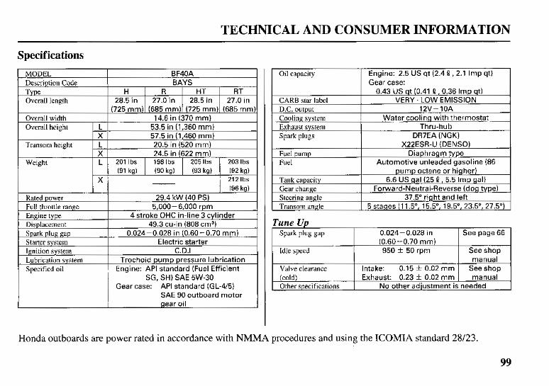
TECHNICAL AND CONSUMER INFORMATION
Specifications MODEL
28.5in I 27.0in I 28.5in I 27.0in Overall length H I R I H T I R T Type
BAYS Description Code BF40A
L Overall width 14.6 in (370 mm) Overall height L
20.5 in (520 mm) L Transom height
53.5 in (1,360 mm)
2051bs 1981bs 201 Ibs L Weight 2031bs (91 kg) (90 kg) (93 kg) (92 kg)
X 212 Ibs
X
X
57.5 in (1,460 mm)
24.5 in (622 mm)
- I (96kg)
Rated power 29.4 kW (40 PS) Full throttle range
0.024-0.028 in (0.60-0.70 mm) Spark plug gap 49.3 cu-in (808 cm3) Displacement
4 stroke OHC in-line 3 cylinder Engine type 5,000-6,000 rpm
Starter system
Engine: API standard (Fuel Efficient Specified oil Trochoid pump pressure lubrication Lubrication system
C.D.1 Ignition system Electric starter
SG, SH) SAE 5W-30 Gear case: API standard (GL-4/51
SAE 90 outboard motor gear oil
Oil capacity Gear case: Engine: 2.5 US qt (2.4 Q ,2.1 Imp qt)
0.43 US qt (0.41 Q ,0.36 Imp qt) CARB star label
DR7EA (NGK) Spark plugs Thru-hub Exhaust system
Water cooling with thermostat Cooling system 12V-10A D.C. output
VERY. LOW EMISSION
Fuel pump Diaphragm type Fuel Automotive unleaded gasoline (86
X22ESR-U (DENSO)
pump octane or higher) Tank capacity
5 stages (11.5', 15.5", 19.5", 23.5", 27.5") Transom angle 37.5" right and left Steering angle
Forward-Neutral-Reverse (dog type) Gear change 6.6 US gal (25 8 , 5.5 Imp gal)
Tune U p I Spark plug gap 0.024-0.028 in I Seepage66
Idle speed 950 * 50 rpm See shop
Valve clearance manual
Honda outboards are power rated in accordance with NMMA procedures and using the ICOMIA standard 28/23.
99
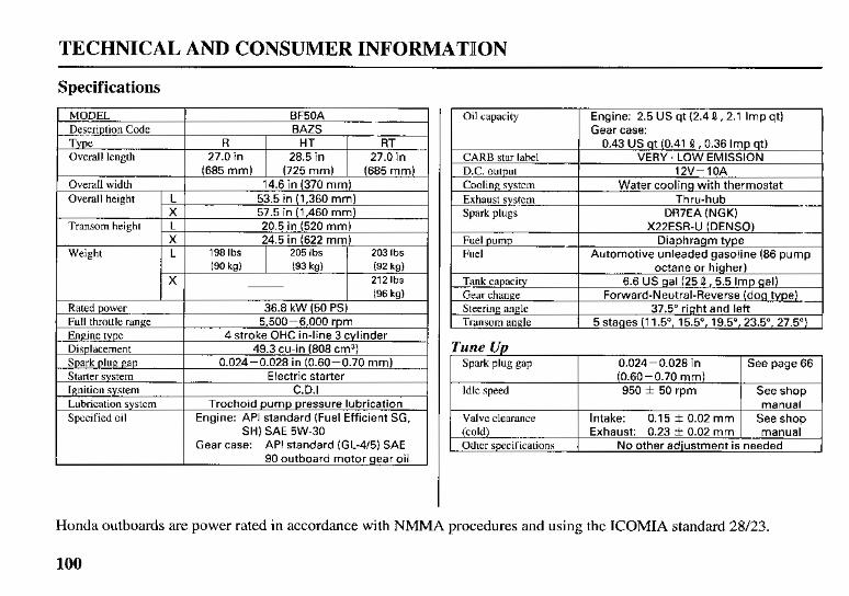
TECHNICAL AND CONSUMER INFORMATION
Specifications MODEL
27.0in I 28.5in 1 27.0in Overall length RT HT R Type
BAZS Description Code BF50A
(685mm) I (725mm) 1 (685mm)
53.5 in (1,360 mm) 57.5 in (1,460 r n r n )
Overall width
L Transom height X L Overall height
14.6 in (370 mrn)
20.5 in (520 mm)
Weight L 1981bs 205 Ibs 203 Ibs (90 kg)
212 Ibs X (92 kg) (93 kg)
X 24.5 in (622 rnm)
.. I (96kg) Rated power
5,500-6,000 rpm Full throttle range 36.8 kW (50 PS)
Engine type
Electric starter Starter system 0.024-0.028 in (0.60-0.70 mm) Spark plug gap
49.3 cu-in (808 cm3) Displacement 4 stroke OHC in-line 3 cylinder
Engine: API standard (Fuel Efficient SG, Specified oil Trochoid pump pressure lubrication Lubrication system
C.D.1 Ignition system
~~~
SH) SAE 5W-30 Gear case: API standard (GL-4/5) SAE
90 outboard motor gear oil
Oil capacity Gear case: Engine: 2.5 US qt (2.4 0 , 2.1 Imp qt)
I 0.43 US qt (0.41 0, 0.36 Imp qt) CARB star label VERY. LOW EMISSION D.C. output
Water cooling with thermostat Cooling system 12V-10A
Exhaust system DR7EA (NGK) Spark plugs
Thru-hub
Tune Up I Spark P b gap 0.024-0.028 in I See page 66 1
Idle speed 950 f 50 rpm See shop
Valve clearance manual
Honda outboards are power rated in accordance with NMMA procedures and using the ICOMIA standard 28/23.
n4)o
TECHNICAL AND CONSUMER INFORMATION ~~
CONSUMER INFORMATION
Honda Publications
These publications will give you additional information for maintaining and repairing your outboard motor. You may order them from your Honda marine dealer.
Shop Manual
This manual covers complete maintenance and overhaul procedures. It is intended to be used by a skilled technician.
Parts Catalog
This manual provides complete, illustrated parts lists.
Warranty Service Information
Honda Marine dealership personnel are trained professionals. They should be able to answer any question you may have. If you encounter a problem that your dealer does not solve to your satisfaction, please discuss it with the dealership’s management. The Service Manager or General Manager can help. Almost all problems are solved in this way.
If you are dissatisfied with the decision made by the dealership’s management, contact the Honda Marine Customer Relations Office. You can write:
American Honda Motor Co., Inc. Marine Division Customer Relations Office 4900 Marconi Drive Alpharetta, Georgia 30005-8847
Or telephone: (770) 497-6400
When you write or call, please give us this information:
Model and serial numbers (p. 92 )
Name of the dealer who sold the outboard motor to you
Name and address of the dealer who services your outboard motor
Date of purchase
Your name, address, and telephone number
A detailed description of the problem
101
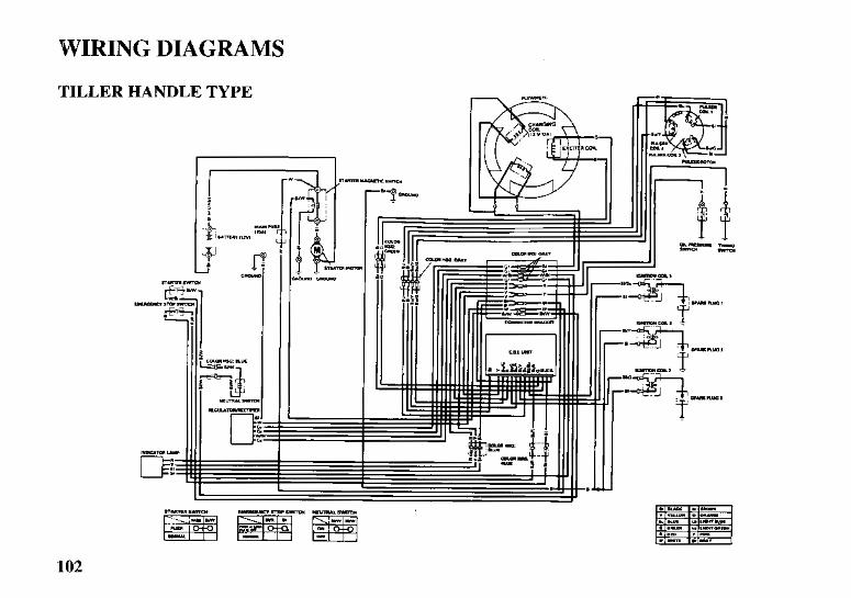
WIRING DIAGRAMS
TILLER HANDLE TYPE
602
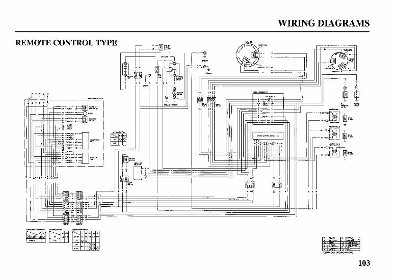
WIRING DIAGRAMS
REMOTE CONTROL TYPE
r r
I L t
I J
1 -1 L i
4 1 F i r I I I I
- 1 1 1 I 1 I 1 I Ti rh
103
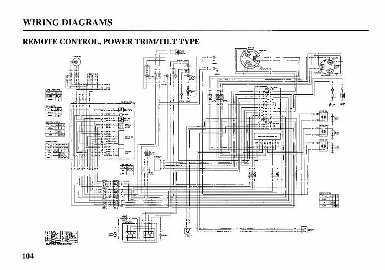
POT
XXMOd '7OXLN03
INDEX
Anodes ............................................................................ 27 Replacement ............................................................... 73
ARE YOU READY TO GET UNDER WAY ? .......... 30
BATTERY WILL NOT CHARGE AND ELECTRIC STARTER WILL NOT
OPERATE .............................................................. 87 BEFORE OPERATION ................................................. 30 BREAK-IN PROCEDURE ............................................ 32
Carburetor Modification for High Altitude Operation .................................................................... 93
Choke/Fast Idle Lever (side-mount type) ...................... 18 Choke Knob .................................................................... 15 Common Controls .......................................................... 20 COMPONENT AND CONTROL LOCATIONS ......... 11 CONSUMER INFORMATION .................................. 10 1 CONTROLS ................................................................... 14 CONTROLS AND FEATURE IDENTIFICATION
CODES ....................................................................... 10
Cooling System Indicator ............................................... 27 CRUISING ..................................................................... 48
CONTROLS AND FEATURES ................................... 10
Electric Starter Button .................................................... 14
Emission Control System Information .......................... 95 Engine
EMERGENCY STARTING .......................................... 40
Cover Latches ................................................................... 22 REMOVAL AND INSTALLATION .................... 60
Change .................................................................... 62 Level Check ........................................................... 61
Stop Switch and Switch Clip ..................................... 14
Oil
Recommendations .................................................. 64
Fuel Cap Vent Knob (optional equipment) ........................ 28 HOSE CONNECTIONS ............................................ 34 Gauge (optional equipment) ....................................... 24
Priming Bulb .............................................................. 29 RECOMMENDATIONS ........................................... 69 Pump Filter Inspection and Replacement .................. 70
PRIMING ................................................................... 35
105
Gearshift Lever ............................................................... 16 GearshifdTrottle Control Lever
LR. LRT and XRT Types (remote control) Side-Mount Type ................................................... 18
GEARSHIFTING AND THROTTLE OPERATION ... 45 LM and LHT Types (tiller handle) ............................. 45 LR, LRT and XRT Types (remote control) ............... 46
Ignition Switch LR, LRT and XRT Types (remote control)
Side-Mount Type ................................................... 16 IMPORTANT SAFETY INFORMATION ..................... 7 INDEX .......................................................................... 105 INDICATORS ................................................................ 25 INSTRUMENTS ............................................................ 24 IS YOUR OUTBOARD MOTOR
READY TO GO ? ..................................................... 30
Lubrication Points .......................................................... 65
MAINTENANCE SAFETY .......................................... 55 MAINTENANCE SCHEDULE .................................... 57 Manual Choke Knob ...................................................... 21 MANUAL RELEF VALVE ................................... 22, 60 MOORING, BEACHING, LAUNCHING .................... 52
Oil Pressue Indicator ...................................................... 25 OIL PRESSURE INDICATOR LIGHT GOES
OFF AND ENGINE SPEED IS LIMITED ............... 88 OPERATION ................................................................. 32 OTHER FEATURES ..................................................... 27 OUTBOARD MOTOR SAFETY .................................... 7 Overheating Indicator ..................................................... 26 OVERHEATING INDICATOR LIGHT COMES
ON AND ENGINE SPEED IS LIMITED ................ 89 Overrev Limiter .............................................................. 27 Oxygenated Fuels ........................................................... 94
PORTABLE FUEL TANK (optional equipment) ... 28. 34 Portable Fuel Tank and Filter Cleaning
(optional equipment) .................................................. 72 Power Tilt Switch ........................................................... 20 Power TridTilt Switch ................................................. 20 Propeller Replacement ................................................... 74
106
REFUELING .................................................................. 68 REMOVAL FROM STORAGE .................................... 80
SAFE OPERATING PRECAUTIONS ......................... 32 SAFETY LABEL LOCATIONS ..................................... 9 Serial Number Locations ................................................ 92 SERVICING YOUR OUTBOARD MOTOR ............... 54 SHALLOW WATER OPERATIONS ........................... 50 Spark Plug Service ......................................................... 66 Specifications ................................................................. 99 Star Label ....................................................................... 97 STARTING THE ENGINE
LH and LHT Types (tiller handle) ............................. 35
LH and LHT Types (tiller handle) ............................. 47
Steering Friction Lever ................................................... 47
LR. LRT and XRT Types (remote control) ............... 38 STEERING ..................................................................... 47
LR. LRT and XRT Types (remote control) ............... 47
STOPPING THE ENGINE Emergency Engine Stopping ...................................... 43 Normal Engine Stopping ............................................ 43
STORAGE ..................................................................... 75 STORAGE PRECAUTIONS ......................................... 80 STORAGE PREPARATION ......................................... 75
Cleaning and Flushing ............................................... 75 Engine oil ................................................................... 79 Fuel ............................................................................. 78
SUBMERGED MOTOR ................................................ 90 Switch Clip and Emergency Stop Switch
LR. LRT and XRT Types (remote control) Side-Mount Type ................................................... 17
Tachometer (optional equipment) .................................. 24 TAKING CARE OF UNEXPECTED PROBLEMS ..... 82 TECHNICAL AND CONSUMER INFORMATION ... 92 TECHNICAL INFORMATION .................................... 92 THE IMPORTANCE OF MAINTENANCE ................ 54 Throttle Friction Knob ................................................... 16
Tilt Lever (gas assisted/LH and LR types) .................... 21 Tilt Lock Lever ............................................................... 22 TOOL KIT AND EMERGENCY STARTER ROPE
(optional equipment) .................................................. 56 TRANSOM ANGLE ADJUSTMENT .......................... 33 Transom Angle Adjusting Rod ...................................... 23
Throttle Grip ................................................................... 15
107
INDEX
TRANSPORTING ......................................................... 81
ON BOAT .............................................................. 81
FROM BOAT ........................................................ 81 Trim Meter (optional equipment) .................................. 24 Trim Tab ......................................................................... 23 TRIM TAB ADJUSTMENT ......................................... 59
WITH OUTBOARD MOTOR INSTALLED
WITH OUTBOARD MOTOR REMOVED
WIRING DIAGRAMS ................................................ 102
108

0909-PMZ- LEX00 909PMZ LE