Embed Size (px)
Citation preview
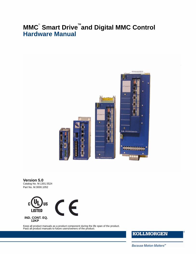
MMC©
Smart DriveTM
and Digital MMC ControlHardware Manual
Keep all product manuals as a product component during the life span of the product. Pass all product manuals to future users/owners of the product.
Version 5.0Catalog No. M.1301.5524Part No. M.3000.1052
IND. CONT. EQ.12KP


Record of Revisions
Third party brands and trademarks are the property of their respective owners
Technical changes to improve the performance of the equipment may be made without notice!Printed in USA All rights reserved. No part of this work may be reproduced in any form (by printing, photocopying, microfilm or any othermethod) or processed, copied or distributed by electronic means without the written permission of Kollmorgen.
Edition Valid for Description
03/2007 PiCPro V16.1 Major Update10/2007 PiCPro V16.1 SP2 Added MMC-D805/2008 PiCPro V16.1 SP3 Added 4 analog drives, various manual updates09/2008 PiCPro V17.0 Added S200-DLS Drives12/2008 PiCPro V17.0 Rev 1 fixed various typos01/2009 PiCPro V17.0 Rev 2 added CE/UL info to S200-DLS03/2009 PiCPro V17.0 Rev 3 added Aux Feedback Connector to S200DLS02/2010 PiCPro V18.0 Kollmorgen Branding & S200 BiSS03/2011 PiCPro V18.0 SP1 230V, 3-Phase Drives
Kollmorgen - March 2011 1

2
NOTE
These products are being manufactured and sold by G & L Motion Control, Inc., a Kollmorgen company.
Progress is an on-going commitment at Kollmorgen. We continually strive to offer the most advanced products in the industry; therefore, information in this document is subject to change without notice. The text and illustrations are not binding in detail. Kollmorgen shall not be liable for any technical or editorial omissions occurring in this document, nor for any consequential or incidental damages resulting from the use of this document.
Kollmorgen makes every attempt to ensure accuracy and reliability of the specifications in this publication. Specifications are subject to change without notice. Kollmorgen provides this information “AS IS” and disclaims all warranties, express or implied, including, but not limited to, implied warranties of merchantability and fitness for a particular purpose. It is the responsibility of the product user to determine the suitability of this product for a specific application.
DO NOT ATTEMPT to use any Kollmorgen product until the use of such product is completely understood. It is the responsibility of the user to make certain proper operation practices are understood. Kollmorgen products should be used only by qualified personnel and for the express purpose for which said products were designed.
Should information not covered in this document be required, contact the Customer Service Department, Kollmorgen, 672 South Military Road, P.O. Box 1960, Fond du Lac, WI 54936-1960. Kollmorgen can be reached by telephone at (920) 921-7100 or (800) 558-4808 in the United States or by e-mail at [email protected].
Catalog No. (Order No.) M.1301.5524
Printed Version Part No. M.3000.1052
Electronic Version Part No. M.3000.1051
Release 03222011
©2011, Kollmorgen
Kollmorgen - March 2011

MMC Smart Drive Hardware Manual - TABLE OF CONTENTS
Table of Contents Table of Contents................................................................................................................................3
1 Introduction to the MMC Smart Drive.............................................................................................7 1.1 Overview...................................................................................................................................7 1.2 Contents of This Manual...........................................................................................................7 1.3 Software and Manuals..............................................................................................................8
1.3.1 Required Software and Manuals.....................................................................................8 1.3.2 Suggested Manuals ........................................................................................................8
1.4 Kollmorgen Support Contact ....................................................................................................9
2 Safety Precautions.........................................................................................................................11 2.1 System Safety ........................................................................................................................11
2.1.1 User Responsibility .......................................................................................................11 2.1.2 Safety Instructions.........................................................................................................11
2.2 Safety Signs ...........................................................................................................................12 2.3 Warning Labels.......................................................................................................................12 2.4 Safety First .............................................................................................................................13 2.5 Safety Inspection ....................................................................................................................13
2.5.1 Before Starting System .................................................................................................13 2.6 After Shutdown .......................................................................................................................13 2.7 Operating Safely.....................................................................................................................14 2.8 Electrical Service & Maintenance Safety................................................................................14 2.9 Safe Cleaning Practices .........................................................................................................15
3 Installing the MMC Smart Drive ....................................................................................................17 3.1 Storing the Drive Before Installation ......................................................................................17 3.2 Unpacking the Drive ...............................................................................................................17 3.3 Handling an MMC Smart Drive...............................................................................................17 3.4 Inspecting the Drive Before Installation ..................................................................................17 3.5 Complying with European Directives......................................................................................18 3.6 Conforming with UL and cUL Standards ................................................................................18 3.7 General Installation and Ventilation Requirements ................................................................18 3.8 Controlling Heat Within the System........................................................................................19 3.9 Bonding .................................................................................................................................20
3.9.1 Bonding a Subpanel Using a Stud ................................................................................20 3.9.2 Bonding a Ground Bus Using a Stud ............................................................................20 3.9.3 Bonding a Ground Bus or Chassis Using a Bolt ...........................................................20 3.9.4 Grounding Multiple Drive Cabinets ...............................................................................21 3.9.5 Bonding Multiple Subpanels..........................................................................................21
3.10 Drive Mounting Guidelines ...................................................................................................21 3.11 Drive System Grounding Procedures ...................................................................................22
3.11.2 Grounding Multiple Drives in the Same Cabinet .........................................................25 3.12 System Wiring Guidelines ....................................................................................................25
3.12.1 Recommended Signal Separation ..............................................................................26 3.12.2 Building Your Own Cables ..........................................................................................28 3.12.3 Routing Cables............................................................................................................28
3.13 Wiring the Drive ....................................................................................................................28 3.13.1 Sizing the 24V Power Supply......................................................................................28 3.13.2 System AC Power Wiring Guidelines .........................................................................29 3.13.3 Connecting Interface Cables ......................................................................................30 3.13.4 Preparing Motor Connection Wires ............................................................................31
Kollmorgen - March 2011 3
4
MMC Smart Drive Hardware Manual - TABLE OF CONTENTS
4 System Power Devices ................................................................................................................. 35 4.1 AC Input Power Requirements............................................................................................... 35 4.2 Protection ............................................................................................................................... 37
4.2.1 Motor Overload Protection............................................................................................ 37 4.2.2 Motor Thermal Protection ............................................................................................. 37 4.2.3 230V Smart Drive Protection Requirements................................................................. 37 4.2.4 460V Smart Drive Protection Requirements................................................................. 38
4.3 Line Reactors ......................................................................................................................... 42 4.3.1 Specifications and Dimensions for Required Line Reactors......................................... 43
4.4 Isolation Transformers ........................................................................................................... 49 4.5 External Shunts...................................................................................................................... 50
4.5.1 Choosing External Shunts ............................................................................................ 50 4.5.2 Mounting External Shunts ............................................................................................ 52 4.5.3 Connecting Shunt Modules .......................................................................................... 58
4.5.3.1 230V, 1-Phase MMC Smart Drive Shunt Wiring ................................................. 58 4.5.3.2 460V, 3-Phase MMC Smart Drive Shunt Wiring ................................................. 59
4.6 Line Filters.............................................................................................................................. 60 4.6.1 Line Filters and CE Compliance ................................................................................... 60 4.6.2 Dimensions for 230V Line Filters.................................................................................. 65 4.6.3 Dimensions for 460V Line Filters.................................................................................. 66
5 230V 1/3 Phase MMC Smart Drive................................................................................................ 67 5.1 Control Section Connectors, Switches, LEDs........................................................................ 69
5.1.1 LEDs............................................................................................................................. 69 5.1.2 PiCPro Port (Digital Interfaced Drives) ......................................................................... 69 5.1.3 PiCPro Port (Analog Drives)......................................................................................... 71 5.1.4 Node Address Rotary Switch (Digital Interfaced MMC-SD Only) ................................. 74 5.1.5 Digital Link Ports (Digital Interfaced MMC-SD Only) .................................................... 75 5.1.6 Feedback Connectors (F1 & F2) .................................................................................. 77
5.1.6.1 Feedback Connectors (F1 and F2) Details ......................................................... 82 5.1.6.2 Feedback Port (F1/F2) to Motor Cables.............................................................. 86
5.1.7 Drive I/O Connector (IO)............................................................................................... 98 5.2 Power Section Connectors................................................................................................... 105
5.2.1 24 VDC IN/Brake Connector ...................................................................................... 106 5.2.1.1 "EN" requirements and Safe-off Operation ....................................................... 107
5.2.2 Power Connector........................................................................................................ 108 5.2.3 DC Bus/Regen Connector (3-phase drive only) ......................................................... 111
5.3 Specifications - 230V MMC Smart Drive.............................................................................. 112 5.3.1 General Data for all 230V Models ............................................................................. 112 5.3.2 Physical and Electrical Data for 230V Drives ............................................................. 115
5.4 Dimensions for 230V MMC Smart Drive .............................................................................. 116
6 460V 3-Phase MMC Smart Drive................................................................................................. 123 6.1 Control Section Connectors, Switches, LEDs...................................................................... 123 6.2 Power Section Connectors................................................................................................... 123
6.2.1 Size 1 Power Section Connectors .............................................................................. 123 6.2.1.1 Shunt/DC Bus Connector ................................................................................. 125 6.2.1.2 AC Power Connector ....................................................................................... 126 6.2.1.3 Motor Connector ............................................................................................... 126 6.2.1.4 24V Power Connector (J1)................................................................................ 127 6.2.1.5 Motor Brake Connector (X101) ........................................................................ 128
6.2.2 Size 2 Power Section Connectors .............................................................................. 128 6.2.2.1 AC Power Connector ........................................................................................ 130 6.2.2.2 Motor Connector ............................................................................................... 131
Kollmorgen - March 2011
MMC Smart Drive Hardware Manual - TABLE OF CONTENTS
6.2.2.3 24V Power Connector (J1) ................................................................................132 6.2.3 Size 3 Power Section Connectors...............................................................................133
6.2.3.1 AC Power Connector .........................................................................................135 6.2.3.2 Motor Connector ................................................................................................136 6.2.3.3 24V Power Connector (J1) ................................................................................137 6.2.3.4 Motor Brake Connector (X101)..........................................................................138
6.2.4 Size 4 Power Section Connectors...............................................................................138 6.2.4.1 AC Power Connector ........................................................................................140 6.2.4.2 Motor Connector ................................................................................................141 6.2.4.3 24V Power Connector (J1) ................................................................................142 6.2.4.4 Motor Brake Connector (X101)..........................................................................143 6.2.4.5 Fan Connector (X36) .........................................................................................144
6.3 Typical 460V Drive Connection Layout ................................................................................145 6.4 Specifications - 460V MMC Smart Drive) .............................................................................146
6.4.1 Common Data for Size 1, 2, 3, 4 (All Models).............................................................146 6.4.2 Physical/Electrical Data for 460V Size 1 Smart Drives ...............................................149 6.4.3 Physical/Electrical Data for 460V Size 2 Smart Drives ...............................................151 6.4.4 Physical/Electrical Data for 460V Size 3 Smart Drives ...............................................154 6.4.5 Physical/Electrical Data for 460V Size 4 Smart Drives ...............................................157
6.5 Dimensions for the 460V Smart Drives ...............................................................................159
7 S200-DLS Drive ............................................................................................................................167 7.1 S200-DLS Option Card.........................................................................................................169
7.1.1 LED Indicators.............................................................................................................169 7.1.2 Diagnostic Indicator Details.........................................................................................169 7.1.3 Digital Link LEDs.........................................................................................................169 7.1.4 Node Address Rotary Switches ..................................................................................169 7.1.5 Digital Link Ports .........................................................................................................171 7.1.6 Auxiliary Feedback Port ..............................................................................................173 7.1.7 Drive I/O and I/O Power Ports.....................................................................................180 7.1.8 Drive I/O Port Details ..................................................................................................182
7.1.8.1 Drive I/O Port Outputs .......................................................................................183 7.1.8.2 Drive I/O Port Inputs ..........................................................................................183 7.1.8.3 Drive I/O Port Wiring Example...........................................................................183
7.2 Power Section Wiring Accessories.......................................................................................184 7.3 Specifications - S200-DLS Drive ..........................................................................................186
8 Motor Cables & Connectors........................................................................................................189 8.1 Flex Cable Installation Guidelines ........................................................................................189
8.1.1 Bending Radius...........................................................................................................189 8.1.2 Cable Tension .............................................................................................................190
8.2 Flex Cable Installation ..........................................................................................................190 8.3 AKM/DDR Motor Power Cables ...........................................................................................192 8.4 LSM/MSM Motor Connector Kits .........................................................................................193 8.5 LSM/MSM Motor Power Cables ...........................................................................................194 8.6 LSM/MSM Motor Fan Cables ...............................................................................................197
9 Maintenance and Troubleshooting.............................................................................................199 9.1 Maintenance ........................................................................................................................199 9.2 Troubleshooting....................................................................................................................200
9.2.1 General Troubleshooting.............................................................................................200 9.2.2 Power-On Diagnostics ................................................................................................200
9.2.2.1 Power LED ........................................................................................................200 9.2.2.2 Diagnostic LEDs ................................................................................................200
Kollmorgen - March 2011 5

6
MMC Smart Drive Hardware Manual - TABLE OF CONTENTS
9.2.3 Run-Time Diagnostics ................................................................................................ 201 9.2.3.1 Troubleshooting with the Diagnostic LED (D1) ................................................. 201 9.2.3.2 Troubleshooting using the Status LED (STATUS) ............................................ 208
10 Resolver Interface Option Module ........................................................................................... 213 10.1 Theory of Operation ........................................................................................................... 213 10.2 Installing the Resolver Module ........................................................................................... 213
11 Drive Resident Digital MMC Control ........................................................................................ 217 11.1 Introduction ........................................................................................................................ 217
11.1.1 Overview................................................................................................................... 217 11.1.2 Major Components ................................................................................................... 217
11.2 Installing the Drive Resident Digital MMC Control ............................................................. 219 11.2.1 Installing into a 230V MMC-SD Drive ....................................................................... 219 11.2.2 Installing into a 460V MMC-SD Drive ....................................................................... 219
11.3 System Wiring Guidelines .................................................................................................. 220 11.4 Starting an Operation ......................................................................................................... 221
11.4.1 Connecting the Drive Resident Digital MMC Control to the Application ................... 221 11.4.2 Basic Setup and Maintenance Procedures .............................................................. 221 11.4.3 Start-up Diagnostics ................................................................................................. 222
11.4.3.1 Power LED...................................................................................................... 222 11.4.3.2 Scan LED........................................................................................................ 222 11.4.3.3 Drive Resident Digital MMC Control Start-Up Diagnostic LEDs ..................... 223
11.4.4 MMC Run-Time Diagnostics..................................................................................... 224 11.5 Connectors & Operation..................................................................................................... 225
11.5.1 PiCPro Port (P1)....................................................................................................... 225 11.5.2 Block I/O Port (C1) ................................................................................................... 225 11.5.3 User Port .................................................................................................................. 229 11.5.4 Ethernet Port ............................................................................................................ 235 11.5.5 General I/O Port (C5) ............................................................................................... 237
11.5.5.1 DC Output Operation ...................................................................................... 242 11.5.5.2 DC Input Operation ......................................................................................... 244
11.6 Specifications .................................................................................................................... 246
12 Declarations of Conformity ...................................................................................................... 249
Appendix A - 460V MMC Smart Drive DC Bus Sharing............................................................... 255 A.1 Introduction.......................................................................................................................... 255 A.2 DC Bus Sharing with AC Power to All Drives ...................................................................... 255 A.3 DC Bus Sharing with AC Power to One Drive ..................................................................... 257
Index ................................................................................................................................................ 261
Sales and Service ........................................................................................................................... 266
Kollmorgen - March 2011

MMC Smart Drive Hardware Manual - INTRODUCTION TO THE MMC SMART DRIVE
1 Introduction to the MMC Smart Drive1.1 Overview
This manual covers three distinct products:
• The Analog Interfaced MMC Smart Drive (MMC-SD) which receives motion com-mands via a +10V analog input
• The Digital MMC Smart Drive (MMC-SD) which receives motion commands via a digital connection (Digital Link)
• The S200-DLS Digital Link Drive which receives motion commands via a digital connection (Digital Link)
Unless otherwise noted, all of the information in this manual applies to both the Analog Interfaced MMC Smart Drive and the Digital MMC Smart Drive, but not to the S200-DLS Drive. The S200-DLS Drive is detailed exclusively in Chapter 7 on page 167.
Features include:
• 230V, Single Phase drives available with power ratings of .5kW, 1kW, and 2 kW
• 230V, Three Phase drives available with power ratings of .5kW, 1kW, 2 KW, and 3 kW
• Can also operate on Single Phase power
• Built-in Regen circuitry (requires external Regen resistor)
• Optional Safe-off feature
• 460V, Three Phase drives available with power ratings of 1.3kW through 65kW
• Drive firmware in user upgradeable Flash memory
• Serial port for communications with PC-resident PiCPro
• Internal switch to control a mechanical brake
• Green Power LED and yellow Diagnostic LED
• Motor feedback types include incremental encoder, high resolution encoder, and resolver
• Eight General Purpose 24VDC Inputs
• Four General Purpose 24VDC outputs
• +10V command input (Analog Interfaced MMC-SD only)
• Digital Link digital connections (Digital MMC-SD only)
• Optional MMC-SD Control (for Digital MMC-SD only)
• UL Listed and CE Marked.
1.2 Contents of This ManualThis manual includes the following major topics:
• Information to safely operate and maintain the equipment in a safe manner.
• User responsibilities for product acceptance and storage.
Kollmorgen - March 2011 7

8
MMC Smart Drive Hardware Manual - INTRODUCTION TO THE MMC SMART DRIVE
• Power and environmental information for general power, control cabinet, ground-ing, heat control and handling.
• Procedures for mounting, wiring, and connecting the MMC Smart Drive and stan-dard Kollmorgen motors recommended for use with the MMC Smart Drive.
• Recommended drive system wiring guidelines for signal separation and differen-tial devices. Methods to ensure ElectroMagnetic Compatibility.
• The location of connectors on the drive and descriptions of their functionality including I/O, encoder, serial interface and motor/brake connector locations and signal descriptions.
• Physical, electrical, environmental and functional specifications/dimensions.
• Description of the minimal maintenance necessary.
• A troubleshooting chart of potential problems and possible solutions.
• Part numbers and descriptions for the drive and related equipment.
1.3 Software and Manuals
1.3.1 Required Software and ManualsPiCPro (one of the following)
• Professional Edition
• MMC Limited Edition
• Monitor Edition
1.3.2 Suggested Manuals
• Function/Function Block Reference Guide
• Motion Application Specific Function Block Manual
• Ethernet Application Specific Function Block Manual
• General Purpose Application Specific Function BlockManual
Kollmorgen - March 2011

MMC Smart Drive Hardware Manual - INTRODUCTION TO THE MMC SMART DRIVE
1.4 Kollmorgen Support Contact
Contact your local Kollmorgen representative for:
• Sales and order support
• Product technical training
• Warranty support
• Support service agreements
Kollmorgen Technical Support can be reached:
• In the United States, telephone (800) 558-4808
• Outside the United States, telephone (920) 921-7100
• E-mail address: [email protected]
• Web site: www.kollmorgen.com
Kollmorgen - March 2011 9

10
MMC Smart Drive Hardware Manual - INTRODUCTION TO THE MMC SMART DRIVE
Kollmorgen - March 2011

MMC Smart Drive Hardware Manual - SAFETY PRECAUTIONS
2 Safety Precautions
READ AND UNDERSTAND THIS SECTION IN ITS ENTIRETY BEFORE UNDERTAKING INSTALLATION OR ADJUSTMENT OF THE MMC SMART DRIVE AND ANY ASSOCIATED SYSTEMS OR EQUIPMENT
The instructions contained in this section will help users to operate and maintain the equipment in a safe manner.
PLEASE REMEMBER THAT SAFETY IS EVERYONE'S RESPONSIBILITY
2.1 System Safety The basic rules of safety set forth in this section are intended as a guide for the safe operation of equipment. This general safety information, along with explicit service, maintenance and operational materials, make up the complete instruction set. All personnel who operate, service or are involved with this equipment in any way should become totally familiar with this information prior to operating.
2.1.1 User ResponsibilityIt is the responsibility of the user to ensure that the procedures set forth here are followed and, should any major deviation or change in use from the original specifications be required, appropriate procedures should be established for the continued safe operation of the system. It is strongly recommended that you contact your OEM to ensure that the system can be safely converted for its new use and continue to operate in a safe manner.
2.1.2 Safety Instructions
• Do not operate your equipment with safety devices bypassed or covers removed.
• Only qualified personnel should operate the equipment.
• Never perform service or maintenance while automatic control sequences are in operation.
• To avoid shock or serious injury, only qualified personnel should perform mainte-nance on the system.
Kollmorgen - March 2011 11
12
MMC Smart Drive Hardware Manual - SAFETY PRECAUTIONS
• GROUNDING (Protective Earth)
The equipment must be grounded (connected to the protective earth connection) according to OEM recommendations and to the latest local regulations for electrical safety. The grounding (protective earth) conductor must not be interrupted inside or outside the equipment enclosures. The wire used for equipment grounding (connection to protective earth) should be green with a yellow stripe.
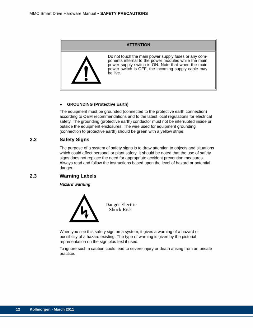
2.2 Safety Signs The purpose of a system of safety signs is to draw attention to objects and situations which could affect personal or plant safety. It should be noted that the use of safety signs does not replace the need for appropriate accident prevention measures. Always read and follow the instructions based upon the level of hazard or potential danger.
2.3 Warning LabelsHazard warning
When you see this safety sign on a system, it gives a warning of a hazard or possibility of a hazard existing. The type of warning is given by the pictorial representation on the sign plus text if used.
To ignore such a caution could lead to severe injury or death arising from an unsafe practice.
ATTENTION
Do not touch the main power supply fuses or any com-ponents internal to the power modules while the mainpower supply switch is ON. Note that when the mainpower switch is OFF, the incoming supply cable maybe live.
Danger Electric Shock Risk
Kollmorgen - March 2011
MMC Smart Drive Hardware Manual - SAFETY PRECAUTIONS
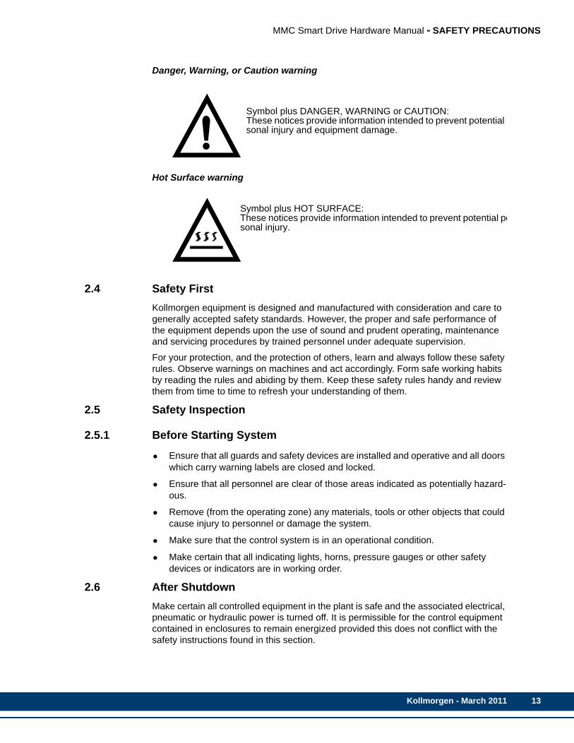
Danger, Warning, or Caution warning
Hot Surface warning
2.4 Safety FirstKollmorgen equipment is designed and manufactured with consideration and care to generally accepted safety standards. However, the proper and safe performance of the equipment depends upon the use of sound and prudent operating, maintenance and servicing procedures by trained personnel under adequate supervision.
For your protection, and the protection of others, learn and always follow these safety rules. Observe warnings on machines and act accordingly. Form safe working habits by reading the rules and abiding by them. Keep these safety rules handy and review them from time to time to refresh your understanding of them.
2.5 Safety Inspection
2.5.1 Before Starting System
• Ensure that all guards and safety devices are installed and operative and all doors which carry warning labels are closed and locked.
• Ensure that all personnel are clear of those areas indicated as potentially hazard-ous.
• Remove (from the operating zone) any materials, tools or other objects that could cause injury to personnel or damage the system.
• Make sure that the control system is in an operational condition.
• Make certain that all indicating lights, horns, pressure gauges or other safety devices or indicators are in working order.
2.6 After ShutdownMake certain all controlled equipment in the plant is safe and the associated electrical, pneumatic or hydraulic power is turned off. It is permissible for the control equipment contained in enclosures to remain energized provided this does not conflict with the safety instructions found in this section.
Symbol plus DANGER, WARNING or CAUTION: These notices provide information intended to prevent potential sonal injury and equipment damage.
Symbol plus HOT SURFACE:These notices provide information intended to prevent potential pesonal injury.
Kollmorgen - March 2011 13

14
MMC Smart Drive Hardware Manual - SAFETY PRECAUTIONS
2.7 Operating Safely• Do not operate the control system until you read and understand the operating
instructions and become thoroughly familiar with the system and the controls.
• Never operate the control system while a safety device or guard is removed or disconnected
• Where access to the control system is permitted for manual operation, only those doors which provide that access should be unlocked. They should be locked immediately after the particular operation is completed.
• Never remove warnings that are displayed on the equipment. Torn or worn labels should be replaced.
• Do not start the control system until all personnel in the area have been warned.
• Never sit or stand on anything that might cause you to fall onto the control equip-ment or its peripheral equipment.
• Horseplay around the control system and its associated equipment is dangerous and should be prohibited.
• Never operate the equipment outside specification limits.
• Keep alert and observe indicator lights, system messages and warnings that are displayed on the system.
• Do not operate faulty or damaged equipment. Make certain proper service and maintenance procedures have been performed.
2.8 Electrical Service & Maintenance Safety• ALL ELECTRICAL OR ELECTRONIC MAINTENANCE AND SERVICE
SHOULD BE PERFORMED BY TRAINED AND AUTHORIZED PERSONNEL ONLY.
• It should be assumed at all times that the POWER is ON and all conditions treated as live. This practice assures a cautious approach which may prevent accident or injury.
• To remove power:LOCK THE SUPPLY CIRCUIT DISCONNECTING MEANS IN THE OPEN POSI-TION.APPLY LOCKOUT/TAGOUT DEVICES IN ACCORDANCE WITH A DOCU-MENTED AND ESTABLISHED POLICY.
ATTENTION
Know the emergency stop procedures for the system.
Kollmorgen - March 2011

MMC Smart Drive Hardware Manual - SAFETY PRECAUTIONS
• Make sure the circuit is safe by using the proper test equipment. Check test equip-ment regularly.
• There may be circumstances where troubleshooting on live equipment is required. Under such conditions, special precautions must be taken:
• Make sure your tools and body are clear of the areas of equipment which may be live.
• Extra safety measures should be taken in damp areas.
• Be alert and avoid any outside distractions.
• Make certain another qualified person is in attendance.
• Before applying power to any equipment, make certain that all personnel are clear of associated equipment.
• Control panel doors should be unlocked only when checking out electrical equip-ment or wiring. On completion, close and lock panel doors.
• All covers on junction panels should be fastened closed before leaving any job.
• Never operate any controls while others are performing maintenance on the sys-tem.
• Do not bypass a safety device.
• Always use the proper tool for the job.
• Replace the main supply fuses only when electrical power is OFF (locked out).
2.9 Safe Cleaning Practices• Do not use toxic or flammable solvents to clean control system hardware.
• Turn off electrical power (lock out) before cleaning control system assemblies.
• Keep electrical panel covers closed and power off when cleaning an enclosure.
ATTENTION
Care should be taken if you are manually dischargingthe bus capacitors.
WARNING
Even after power to the drive is removed, it may take upto 10 minutes for bus capacitors to discharge to a levelbelow 50 VDC. To be sure the capacitors are dis-charged, measure the voltage across the + and - termi-nals for the DC bus.
Kollmorgen - March 2011 15

16
MMC Smart Drive Hardware Manual - SAFETY PRECAUTIONS
• Always clean up spills around the equipment immediately after they occur.
• Never attempt to clean a control system while it is operating.
• Never use water to clean control equipment unless you are certain that the equip-ment has been certified as sealed against water ingress. Water is a very good conductor of electricity and the single largest cause of death by electrocution.
Kollmorgen - March 2011
MMC Smart Drive Hardware Manual - INSTALLING THE MMC SMART DRIVE
3 Installing the MMC Smart Drive
3.1 Storing the Drive Before Installation The drive should remain in the shipping container prior to installation. If the equipment is not to be used for a period of time, store it as follows:
• Use a clean, dry location
• Maintain the storage temperature and humidity as shown in the specifications section of this manual.
• Store it where it cannot be exposed to a corrosive atmosphere
• Store it in a non-construction area
3.2 Unpacking the DriveRemove all packing material, wedges, and braces from within and around the components. After unpacking, check the name plate Material Number against the purchase order of the item(s) against the packing list. The model number, serial number and manufacturing date code are located on the side of the unit.
3.3 Handling an MMC Smart DriveThe case protects the MMC Smart Drive’s internal circuitry against mechanical damage in shipping and handling.
However, like any electronic device, the circuitry can be destroyed by:
• Conditions exceeding those detailed in the specifications tables shown in the Specifications sections in this manual.
• moisture condensing inside the module
• static discharge
• exposure to a magnetic field strong enough to induce a current in the circuitry
• vibration, and other hazards
3.4 Inspecting the Drive Before InstallationInspect the unit for any physical damage that may have been sustained during shipment.
If you find damage, either concealed or visible, contact your buyer to make a claim with the shipper. If degraded performance is detected when testing the unit, contact your distributor or Kollmorgen. Do this as soon as possible after receipt of the unit.
NOTE
The National Electrical Code and any other governing regional or localcodes overrule the information in this manual. Kollmorgen does not assumeresponsibility for the user’s compliance or non-compliance with any code,national, local or otherwise, for the proper installation of this drive and asso-ciated systems or equipment. Failure to abide by applicable codes createsthe hazard of personal injury and/or equipment damage.
Kollmorgen - March 2011 17

18
MMC Smart Drive Hardware Manual - INSTALLING THE MMC SMART DRIVE
3.5 Complying with European DirectivesFor industrial products installed within the European Union or EEC regions, certain directives and standards apply. See “Conformity” in the Specifications sections of Chapters 5 and 6 for applicable directives.
Servo amplifiers are considered to be subsystems when incorporated into electrical plants and machines for industrial use. The Kollmorgen servo amplifiers have been designed and tested as such. They bear the CE mark and are provided with a Declaration of Conformance. However, it is the overall machine or system design that must meet European Directives and standards. To help the manufacturer of the machine or plant meet these directives and standards, specific guidelines are provided in this documentation. These include such things as shielding, grounding, filters, treatment of connectors and cable layout.
3.6 Conforming with UL and cUL StandardsKollmorgen drives meet safety and fire hazard requirements as outlined in “Conformity” in the Specifications sections of Chapter 12, Declarations of Conformity.
3.7 General Installation and Ventilation Requirements• The drive must be enclosed in a grounded NEMA12 enclosure offering protection
to IP55 such that they are not accessible to an operator or unskilled person, in order to comply with UL® and CE requirements. A NEMA 4X enclosure exceeds these requirements providing protection to IP66.
• The environmental conditions must not exceed those detailed in the specifications tables shown in the Specifications sections in this manual.
• Install the panel on a properly bonded, flat, rigid, non-painted galvanized steel, vertical surface that won’t be subjected to shock, vibration, moisture, oil mist, dust, or corrosive vapors.
• Maintain minimum clearances for proper airflow, easy module access, and proper cable bend radius.
• Plan the installation of your system so that you can perform all cutting, drilling, tapping, and welding with the drive removed from the enclosure. Because the drive is of the open type construction, be careful to keep any metal debris from falling into it. Metal debris or other foreign matter can become lodged in the cir-cuitry, which can result in damage to components.
The MMC Smart Drive is suitable for operation in a pollution degree 2 environment (i.e., normally, only non-conductive pollution occurs). Install the drive away from all sources of strong electromagnetic noise. Such noise can interfere with MMC Smart Drive operation.
Protect the MMC Smart Drive system from all the following:
• conductive fluids and particles
• corrosive atmosphere
• explosive atmosphere
Diagrams included with this manual and recommendations may be modified if necessary so the wiring conforms to current NEC standards or government regulations.
Kollmorgen - March 2011

MMC Smart Drive Hardware Manual - INSTALLING THE MMC SMART DRIVE
3.8 Controlling Heat Within the SystemThe MMC Smart Drive hardware case is designed to promote air circulation and dissipate heat. Normally no fans or air conditioners are needed. However, if the environment outside the control cabinet is hot or humid, you may need to use a fan, heat exchanger, dehumidifier or air conditioner to provide the correct operating environment.
Make sure that the temperature and humidity within the drive cabinet does not exceed that which is shown in the specifications sections of this manual.
Make sure that components installed in the cabinet with the MMC Smart Drive do not raise the temperature above system limits and that any hot spots do not exceed specifications. For example, when heat-generating components such as transformers, other drives or motor controls are installed, separate them from the drive by doing one of the following:
• Place them near the top of the control cabinet so their heat output rises away from the MMC Smart Drive.
• Put them in another control cabinet above or to one side of the cabinet with the MMC Smart Drive. This protects the MMC Smart Drive from both heat and electri-cal noise.
The MMC Smart Drive itself is a source of heat, though in most installations its heat dissipates without harmful effects. System heat is generated from power dissipated by:
• the drive
• field side input/output components
• other drives in the cabinet
• the logic power supply
Table 3-1: Cabinet Clearance Dimensions
Minimum Clearance
Location 230V Drive 460V Drive
Above Drive Body 2.0 in. (50.8 mm) 4.0 in. (100 mm)
Below Drive Body 2.0 in. (50.8 mm) 4.0 in. (100 mm)
Each Side of Drive .50 in. (12.7 mm) None
In Front of Drive (for cabling) 3.0 in. (76.2 mm) 3.0 in. (76.2 mm)
NOTE
Use filtered or conditioned air in ventilated cabinets. The air should be free ofoil, corrosives, or electrically conductive contaminants.
Kollmorgen - March 2011 19
20
MMC Smart Drive Hardware Manual - INSTALLING THE MMC SMART DRIVE
• external shunt resistors
• line reactors
3.9 Bonding Connecting metal chassis, assemblies, frames, shields and enclosures to reduce the effects of electromagnetic interference (EMI) is the process of bonding.
Most paints act as insulators. To achieve a good bond between system components, surfaces need to be paint-free or metal plated. Bonding metal surfaces creates a low-impedance exit path for high-frequency energy. Improper bonding blocks this direct exit path and allows high-frequency energy to travel elsewhere in the cabinet. Excessive high-frequency energy can negatively affect the operation of the drive.
3.9.1 Bonding a Subpanel Using a Stud1. Weld threaded mounting studs to the back of the enclosure.
2. Brush off any non-conductive materials (e.g. paint) from the studs.
3. Remove any non-conductive materials from the front of the subpanel.
4. Position the mounting holes on the subpanel over the mounting studs on the back of the enclosure and slide the subpanel onto the studs.
5. Attach the subpanel to the mounting stud by sliding a star washer over the stud and then turn and tighten a nut onto the stud.
3.9.2 Bonding a Ground Bus Using a Stud1. Weld threaded mounting studs to the back of the subpanel.
2. Brush off any non-conductive materials (e.g. paint) from the studs.
3. Slide a flat washer over the studs.
4. Remove any non-conductive materials from around the mounting hole on the chassis mounting bracket or ground bus.
5. Position the mounting hole of the chassis or ground bus over the studs on the back of the subpanel and slide the mounting bracket or ground bus onto the stud.
6. Attach the subpanel to the subpanel stud by sliding a star washer and then a flat washer over the stud. Turn and tighten a nut onto the stud.
3.9.3 Bonding a Ground Bus or Chassis Using a Bolt1. Brush off any non-conductive materials (e.g. paint) from the threaded bolt (s).
2. Slide a star washer over the threaded bolt (s).
3. Use a subpanel having tapped mounting holes. Remove any non-conductive materials from around the mounting holes on both sides of the subpanel.
4. Turn the threaded bolts into the subpanel mounting holes.
CAUTION
If the MMC Smart Drive is operated outside the recommended environmen-tal limits, it may be damaged. This will void the warranty.
Kollmorgen - March 2011
MMC Smart Drive Hardware Manual - INSTALLING THE MMC SMART DRIVE
5. Slide a star washer onto the threaded end of the bolt.
6. Turn and tighten a nut onto the stud.
7. Slide a flat washer onto the threaded end of the bolt.
8. Position the mounting holes on the groundbus or mounting bracket over the threaded bolts and turn the bolts until they come through the grounding bus or mounting bracket.
9. Slide a star washer onto the threaded end of the bolt.
10. Slide a flat washer onto the threaded end of the bolt.
11. Turn and tighten a nut onto the bolt.
3.9.4 Grounding Multiple Drive Cabinets1. Mount one bonded ground bus in each cabinet.
2. Designate the cabinet ground bus in one and only one of the cabinets as the com-mon ground bus for all of the cabinets in the system.
3. Connect the ground wires from the ground bus in each individual cabinet ground bus to the designated common ground bus (mounted in only one of the cabinets).
4. Connect the common cabinet ground bus to an external ground system that is connected to a single point ground.
3.9.5 Bonding Multiple SubpanelsKollmorgen recommends bonding both the top and bottom of subpanels sharing the same enclosure. Use a 25.4 mm (1.0 in.) x 6.35 mm (0.25) wire braid. Be sure the area around each wire braid fastener is clear of any non-conductive materials. Bond the cabinet ground bus to at least one of the subpanels.
3.10 Drive Mounting Guidelines• A control cabinet for the MMC Smart Drive should have a NEMA-12 rating or bet-
ter. A cabinet with this rating protects its contents from dust and mechanical dam-age.
• The cabinet must be large enough to provide adequate air circulation for the MMC Smart Drive and other components. Always allow for adequate air flow through the MMC Smart Drive vents.
• The cabinet must have a rigid non-painted galvanized metal surface to mount the MMC Smart Drive on.
NOTE
Subpanels that are not bonded together may not share a common low im-pedance path. This difference in impedance may affect networks and otherdevices that span multiple panels.
Kollmorgen - March 2011 21

22
MMC Smart Drive Hardware Manual - INSTALLING THE MMC SMART DRIVE
• The cabinet door should open fully for easy access.
1. Lay out the positions for the drive and accessories in the enclosure.
2. Attach the drive to the cabinet, first using the upper mounting slots of the drive and then the lower. The recommended mounting hardware is M5 metric(#10-32).
3. Tighten all mounting fasteners.
3.11 Drive System Grounding Procedures The ground of the MMC Smart Drive power source must be connected directly to a Single Point Ground (SPG) tie block. The tie block should be made of brass or copper, bolted or brazed to the control cabinet. If the tie block is bolted rather than brazed, scrape away paint or grease at the point of contact. Put star washers between the tie block and the cabinet to ensure good electrical contact.
Metal enclosures of power supplies, drives, etc., should also have good electrical contact with the SPG.
Metal enclosures of power supplies, drives, etc., should also have good electrical contact with the SPG.
Devices to be connected directly to the Single Point Ground include:
• Plant safety ground.
• Protective earth ground(s) from the MMC Smart Drive power terminals.
• The metal panel or cabinet on which the MMC Smart Drive is mounted.
• “Common” or “0 V” lines from power supplies that provide +24 power to devices and external power to the I/O modules and the devices to which they are con-nected.
IMPORTANT
Post warnings according to National, State, or local codes for the voltagepresent in the control cabinet. Diagrams included with this manual and rec-ommendations may be modified if necessary so the wiring conforms to cur-rent NEC standards or government regulations.
NOTE
This drive contains parts and assemblies that are sensitive to ESD (Electro-static Discharge). Follow static control precautions during installation, test-ing, service, or repair of this assembly. Parts and assemblies can bedamaged if proper precautions are not taken.
CAUTION
The Single Point Ground should be the only common point for all the groundlines. If not, ground loops may cause current flow among components of thesystem which can interfere with proper operation of the MMC Smart Drive.
Kollmorgen - March 2011

MMC Smart Drive Hardware Manual - INSTALLING THE MMC SMART DRIVE
• Protective grounds from the devices themselves, such as device drivers, machin-ery, and operator interface devices.
• Protective earth ground from line and load sides of any AC line filters.
• The ground of the power source of the computer workstation or laptop, if any, from which you monitor the system operation. An AC outlet in the control cabinet is rec-ommended.
• Single point grounds from other control cabinets, if any, in the system.
IMPORTANT
You must ensure that the “0V” or “Common” of all devices connected to theMMC Smart Drive are connected to Single Point Ground (SPG). Failure todo so may result in erratic operation or damage to the MMC Smart Drive anddevices connected to it. Examples of devices connected to the MMC SmartDrive include the power source that supplies power to the MMC Smart Driveand devices connected to the MMC Smart Drive PiCPro Port. Note thatsome devices (for example, a Personal Computer) may have their “0V” and“Protective Earth Ground” connected together internally, in which case onlyone connection has to be made to SPG for that device. Also note that theAC/DC converter for some portable PCs have chassis connected from thewall plug to the PC. The ground for the AC outlet must be connected to theSPG.Also, you must ensure that the MMC Smart Drive “Protective Earth Ground”connection is connected to SPG, and that the MMC Smart Drive is mountedto a metal panel or enclosure that is connected to SPG.
Kollmorgen - March 2011 23

24
MMC Smart Drive Hardware Manual - INSTALLING THE MMC SMART DRIVE
3.11.1 Grounding Requirements
Figure 3-1: Example of Grounding Required for CE Compliant Single Phase 230V Drive System
• Mount the filter as close to the Drive as possible. If the distance exceeds 600 mm (2.0 ft), use shielded cable between the Drive and the filter, strapping the shield to chassis at each end of the cable. This is particularly important for attenuation of higher frequency emissions (5-30 MHz).
+24VCOM
BR+BR-
W
V
U
L2L1
B-
B+
CAUTION - Risk of Electric ShockHigh Voltage may exist up to 10 minutes after removing power
P1
IN
OUT
DC BUS F1
F2
IO
In-coming
Single Point
Drive I/O
Ground (SPG)*
Supply Ground
ENCLOSURETerminal
24V PowerSupply
Supply CircuitDisconnectingMeans
SCPDM
M
AC LineFilter
MotorFeedback
GroundingClamp
Motor Power
* Equipment Ground, AC Common, and DC Common are tied together at one point only, Single Point Ground (SPG).
PE
In-coming AC Power (Mains)
MachineBase
AuxiliaryPower
To Workstationor other Device
Kollmorgen - March 2011
MMC Smart Drive Hardware Manual - INSTALLING THE MMC SMART DRIVE
• Shield or separate the wires connecting the AC power to the filter from other power cables (e.g., connections between the Drive and the filter, motor power cable, etc.). If the connections are not separated from each other, the EMI on the Drive side of the filter can couple over to the source side of the filter, thereby reducing or eliminating the filter’s effectiveness. The coupling mechanism can radiate or allow stray capacitance between the wires.
• Bond the filter and the Drive to a grounded conductive surface (the enclosure) to establish a high frequency (HF) connection. To achieve the HF ground, the con-tact surface interface between the filter, Drive, and the enclosure should be free from paint or any other type of insulator.
• Size the filter following manufacturer recommendations.
• Provide a large enough ground bar to connect all wires with no more than two wires per connection.
• Clamp motor power cable shield for EMC termination.
3.11.2 Grounding Multiple Drives in the Same Cabinet 1. Mount a common bonded ground bus in the cabinet.
2. Connect the ground wires for all drives to the common bonded cabinet ground bus.
3. Connect the common bonded cabinet ground bus to an external ground system that is connected to a single point ground.
3.12 System Wiring GuidelinesThe MMC Smart Drive relies on electrical signals to report what is going on in the application and to send commands to it. In addition, signals are constantly being
IMPORTANT
Filter AC power to the drives to be compliant to CE emission requirements.
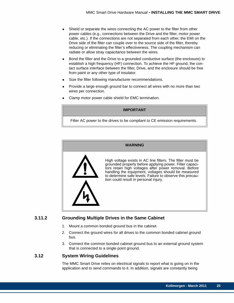
WARNING
High voltage exists in AC line filters. The filter must begrounded properly before applying power. Filter capaci-tors retain high voltages after power removal. Beforehandling the equipment, voltages should be measuredto determine safe levels. Failure to observe this precau-tion could result in personal injury.
Kollmorgen - March 2011 25

26
MMC Smart Drive Hardware Manual - INSTALLING THE MMC SMART DRIVE
exchanged within the system. The MMC Smart Drive is designed for use in industrial environments, but some guidelines should be followed.
This section contains common system wiring configurations, size, and practices that can be used in a majority of applications. National Electrical Code, local electrical codes, special operating temperatures, duty cycles, or system configurations take precedence over the values and methods provided.
Wherever possible, install wiring and related components in the following order:
1. main power line disconnecting means
2. transformer (optional)
3. fuses (SCPD)
4. motor control
5. line reactor (as required)
6. line filter (optional)
7. device protection fuses (as required)
8. drive
9. shunt resistors (optional)
3.12.1 Recommended Signal SeparationKollmorgen recommends separation of low level signals (encoder, analog, communications, fast DC inputs) from high voltage or high current lines. Maintain at least two inches of separation.
Inside a control cabinet, connect the shields of shielded cables at the MMC Smart Drive. It is recommended that factory cables (from Kollmorgen) are used between MMC drives, controls, and motors to ensure CE compliance.
WARNING
Use care when wiring I/O devices to the MMC Smart Driveand when plugging in cables. Wiring the wrong device to theconnector or plugging a connector into the wrong locationcould cause intermittent or incorrect machine operation ordamage to equipment.
Kollmorgen - March 2011

MMC Smart Drive Hardware Manual - INSTALLING THE MMC SMART DRIVE
Figure 3-2: Recommended Signal Separation
To prevent excessive conducted emissions from a DC power source (typically 24V) used for digital I/O, a .001 micro farad capacitor should be used. Connect the capacitor from the +24V DC to COMMON at the distribution terminals.
WARNING: FEEDBACK DEVICE DAMAGE
Feedback Cable Installation and RemovalAll power to the Smart Drive (24 Vdc and main AC power) must be removed before connecting/disconnecting feedback cable connectors at the Smart Drive (F1 and F2 connector) or at the motor feedback device. Also, all connections must be secure when power is applied. Failure to follow these precautions may result in damage to the feedback device or Smart Drive.
MMC
PICPRO COMMUNICATIONS CABLE
MOTOR POWER CABLE
Drive I/O CABLE
24V
CO
M
INCOMING AC POWER
GND
SINGLE-POINT GROUND
SINGLE-POINT GROUND
DC POWER SUPPLY+
PowerConnector
Capacitor
SmartDrive
MOTOR FEEDBACK CABLE
(MAINS)
SINGLE POINT GROUND (SPG)
(.001 uF)
Kollmorgen - March 2011 27

28
MMC Smart Drive Hardware Manual - INSTALLING THE MMC SMART DRIVE
3.12.2 Building Your Own Cables
• Connect the cable shield to the connector shells on both ends of the cable for a complete 360 degree connection.
• Use a twisted pair cable whenever possible, twisting differential signals with each other, and single-ended signals with the appropriate ground return.
3.12.3 Routing CablesGuidelines for routing cables in a cabinet include the following:
• Always route power and control cables separately.
• Do not run high and low voltage wires/cable in the same wireway.
• Cross high and low voltage conductors at 90 degree angles.
• On parallel cable runs, maximize the distance between high and low voltage cables.
• Maintain the least amount of unshielded cable leads.
3.13 Wiring the DriveThese procedures assume you have bonded and mounted your MMC Smart Drive to the subpanel and that there is no power applied to the system.
3.13.1 Sizing the 24V Power Supply When you size your power supply, you must ensure that the supply is large enough to handle the total load. Refer to the specification tables for the +24VDC input power requirements.
In most cases, one power supply can be used for an entire control system. However, depending upon the drives and external I/O used in the application, the power distribution may be split into two or more power supplies.
Use of switches in series with the 24VDC power input is not recommended. The drive contains energy storage capacitors at the inputs. While no harm is done to the drive, this much capacitance across the 24VDC source may cause voltage dips when the switch in series with the 24VDC power is closed.
NOTE
Kollmorgen cables are designed to minimize EMI and are recommendedover hand-built cables.
Kollmorgen - March 2011

MMC Smart Drive Hardware Manual - INSTALLING THE MMC SMART DRIVE
The +24V power to the MMC Smart Drive is connected through a Phoenix 5-pin connector with a plug-in terminal block. The ground from the power source and the ground from the MMC Smart Drive must be connected to the Single-Point Ground (SPG). Devices connected to the Drive I/O Port may have their own power sources for input or output control signals provided that each one is:
• at the correct voltage and current levels for the module and the device.
• connected to the same Single-Point Ground that the MMC Smart Drive uses.
It is recommended that the same main disconnect switch be used for the MMC Smart Drive and for all devices in the application.
3.13.2 System AC Power Wiring Guidelines
• Install a supply circuit disconnecting means.
• Install a Short Circuit Protective Device (SCPD).
• Due to high inrush current at power-up, use dual element time delay fuses for the SCPD.
• Install additional device protection fusing (460V models). Only high speed type fuses provide proper protection.
• Refer to the Specifications sections in Chapter 4 of this manual for device and conductor requirements.
• Clamp the motor power cable shield to the drive using the Kollmorgen supplied bracket. Maximum tightening torque for bracket screws is 10 lb-in.
CAUTION
A possible ignition hazard within the MMC Smart Drive exists if excessivecurrent is drawn from the 24 VDC powering the MMC Smart Drive. To pre-vent this possibility (due to improper wiring or 24 VDC supply failure), a fuseshould be used in series with the 24 VDC to the MMC Smart Drive. Specifi-cally, a 4 A max. “UL248 Series” fuse should be used. In addition, the 24VDC shall be supplied by an isolating source such that the maximum opencircuit voltage available to the MMC Smart Drive is not more than 30 VDC.
IMPORTANT
No matter how the system is installed, before you connect the MMC SmartDrive to the application, make sure that power is off to the system and to thedevices that are wired to the MMC Smart Drive.
NOTE
In addition to the guidelines listed below, follow all national and local electri-cal codes and regulations.
Kollmorgen - March 2011 29
30
MMC Smart Drive Hardware Manual - INSTALLING THE MMC SMART DRIVE
• Use shielded cables and AC line filters (for CE Compliance). Make sure that wir-ing from the drive to the line filter is as short as possible. Locate common ground-ing bus bars as close as possible to the drive. The braid shield of the cable should be clamped at the drive or mounting panel.
• Power connections for each drive in a system should be separately connected directly to the AC power supply. Do not daisy chain drive power connections.
• Make sure the phase to neutral ground voltage does not exceed the input ratings of the drive when using an autotransformer.
3.13.3 Connecting Interface Cables
• Plug PiCPro cable into the PiCPro port (9-pin D-shell for the Analog Interfaced MMC-SD, and 6-pin mini-din for the Digital Interfaced MMC-SD).
• Plug the one 15-pin D-shell, Feedback cable into the FBK1 connector.
• Plug the 26-pin D-shell, Drive I/O cable into the I/O connector.
• Tighten the attachment screws for all cables to the drive connectors.
IMPORTANT
This drive contains ESD (Electrostatic Discharge) sensitive parts and as-semblies. Follow static control precautions when installing, testing, servicing,or repairing components in a drive system.
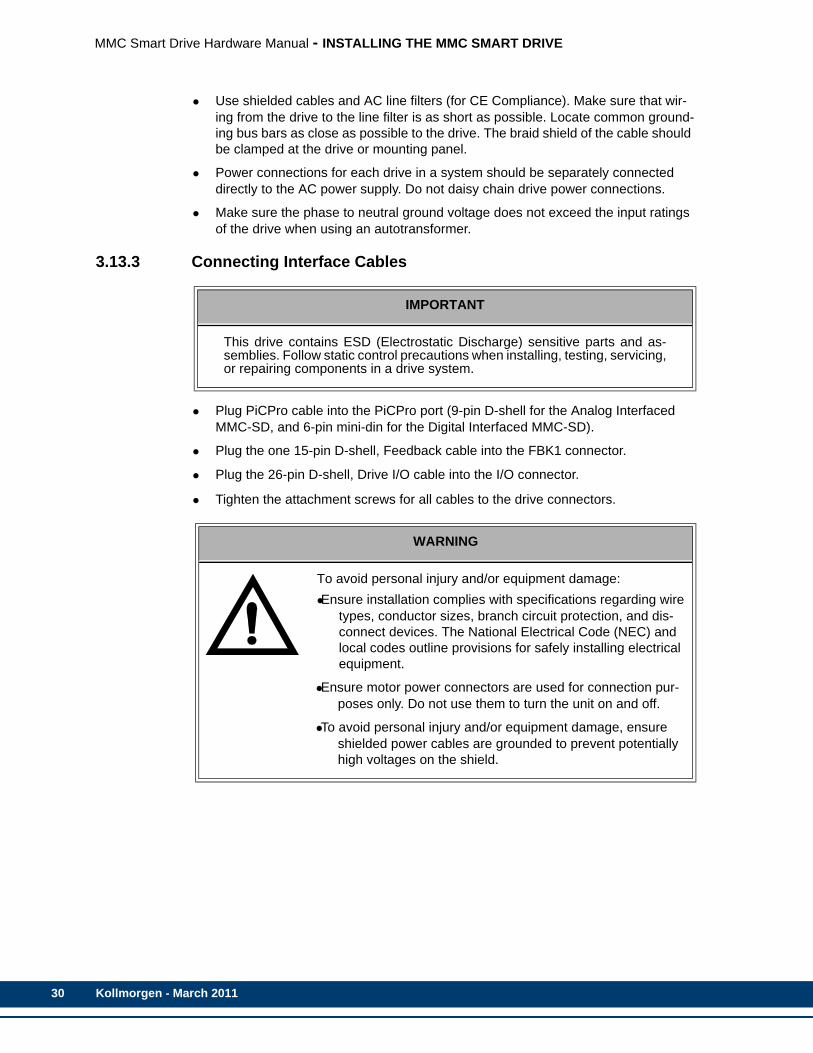
WARNING
To avoid personal injury and/or equipment damage:•Ensure installation complies with specifications regarding wire
types, conductor sizes, branch circuit protection, and dis-connect devices. The National Electrical Code (NEC) and local codes outline provisions for safely installing electrical equipment.
•Ensure motor power connectors are used for connection pur-poses only. Do not use them to turn the unit on and off.
•To avoid personal injury and/or equipment damage, ensure shielded power cables are grounded to prevent potentially high voltages on the shield.
Kollmorgen - March 2011
MMC Smart Drive Hardware Manual - INSTALLING THE MMC SMART DRIVE
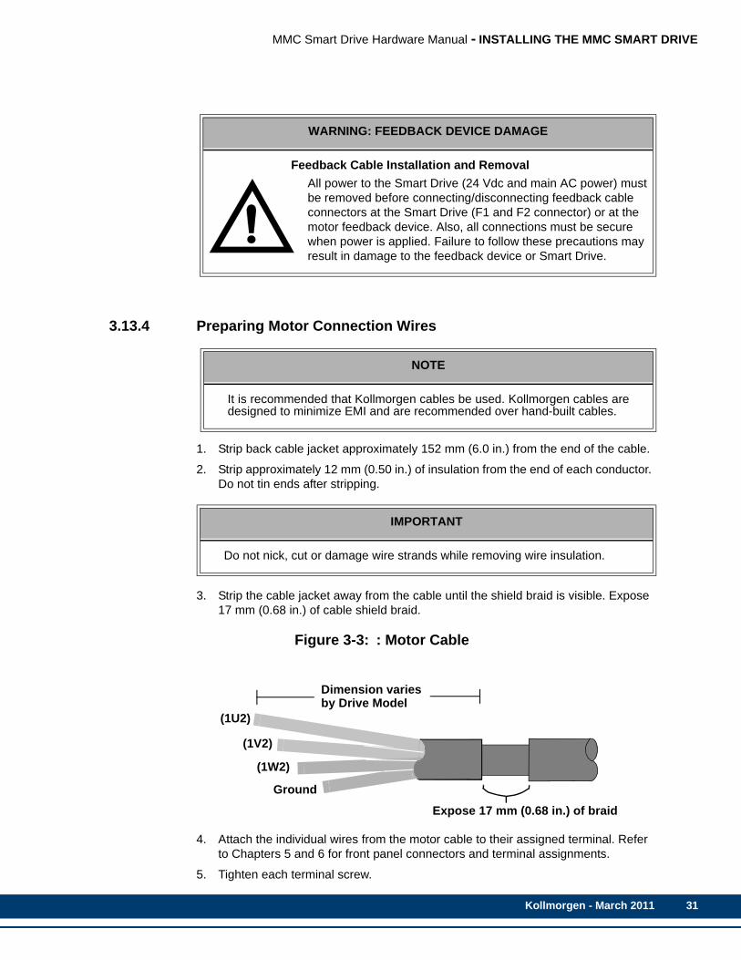
3.13.4 Preparing Motor Connection Wires
1. Strip back cable jacket approximately 152 mm (6.0 in.) from the end of the cable.
2. Strip approximately 12 mm (0.50 in.) of insulation from the end of each conductor. Do not tin ends after stripping.
3. Strip the cable jacket away from the cable until the shield braid is visible. Expose 17 mm (0.68 in.) of cable shield braid.
Figure 3-3: : Motor Cable
4. Attach the individual wires from the motor cable to their assigned terminal. Refer to Chapters 5 and 6 for front panel connectors and terminal assignments.
5. Tighten each terminal screw.
WARNING: FEEDBACK DEVICE DAMAGE
Feedback Cable Installation and RemovalAll power to the Smart Drive (24 Vdc and main AC power) must be removed before connecting/disconnecting feedback cable connectors at the Smart Drive (F1 and F2 connector) or at the motor feedback device. Also, all connections must be secure when power is applied. Failure to follow these precautions may result in damage to the feedback device or Smart Drive.
NOTE
It is recommended that Kollmorgen cables be used. Kollmorgen cables aredesigned to minimize EMI and are recommended over hand-built cables.
IMPORTANT
Do not nick, cut or damage wire strands while removing wire insulation.
Expose 17 mm (0.68 in.) of braid
(1U2)
Ground
Dimension variesby Drive Model
(1V2)
(1W2)
Kollmorgen - March 2011 31

32
MMC Smart Drive Hardware Manual - INSTALLING THE MMC SMART DRIVE
6. Gently pull on each wire to make sure it does not come out of its terminal. Rein-sert and tighten any loose wires.
7. Attach the plastic cover to terminal block
Factory supplied motor power cables for LSM, MSM, FSM, AKM, DDR, CDDR, and YSM Series motors are shielded, and the power cable is designed to be terminated at the drive during installation. A small portion of the cable jacket is removed which exposes the shield braid. The exposed shield braid must be clamped to the drive chassis using the provided clamp and clamp screws
Figure 3-4: Terminating Motor Power Cable for 230V Drive
CAUTION - Risk of Electric ShockHigh Voltage may exist up to 10 minutes after removing power
IO
Motor Cable Jacket
Shield
ClampClamp
ClampScrew
ScrewMotorCable
Kollmorgen - March 2011

MMC Smart Drive Hardware Manual - INSTALLING THE MMC SMART DRIVE
Figure 3-5: Terminating Incoming AC Power (Mains) Cable for 460V Drive
Cable Jacket
ShieldClamp Screw
Clamp Screw
FROM MAINS
CableJacket
Maximum 10 cm fromthe Edge of the Drive
TO MOTOR
Cable
ClampShield Clampedto Bottom of Drive
Jacket
MMC-SD 460 DRIVE
Screw
Shield
Shield Clampedto Mounting Panel
Clamp
Kollmorgen - March 2011 33

34
MMC Smart Drive Hardware Manual - INSTALLING THE MMC SMART DRIVE
Kollmorgen - March 2011

MMC Smart Drive Hardware Manual - SYSTEM POWER DEVICES
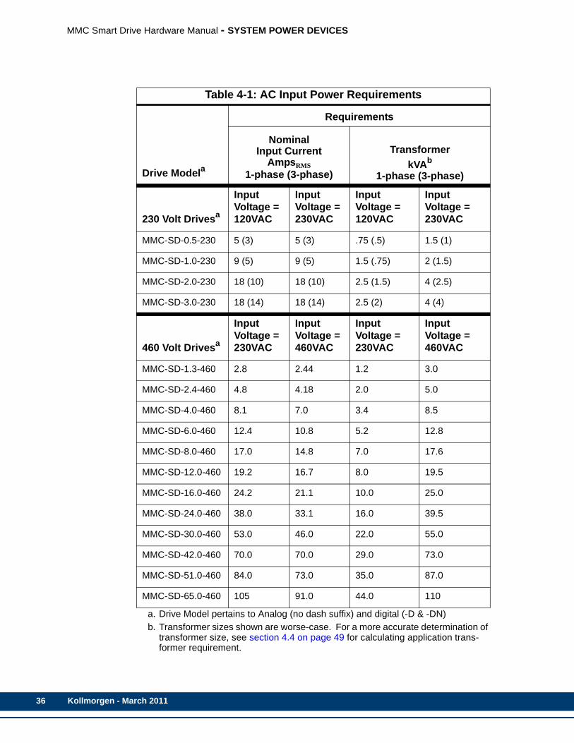
4 System Power Devices4.1 AC Input Power Requirements
The MMC Smart Drive is powered from an external AC power source. The power required for each drive type is listed in Table 4-1.
Kollmorgen - March 2011 35
36
MMC Smart Drive Hardware Manual - SYSTEM POWER DEVICES
Table 4-1: AC Input Power Requirements
Drive Modela
a. Drive Model pertains to Analog (no dash suffix) and digital (-D & -DN)
Requirements
NominalInput Current
AmpsRMS1-phase (3-phase)
TransformerkVAb
1-phase (3-phase)
b. Transformer sizes shown are worse-case. For a more accurate determination of transformer size, see section 4.4 on page 49 for calculating application trans-former requirement.
230 Volt Drivesa
Input Voltage = 120VAC
Input Voltage = 230VAC
Input Voltage = 120VAC
Input Voltage = 230VAC
MMC-SD-0.5-230 5 (3) 5 (3) .75 (.5) 1.5 (1)
MMC-SD-1.0-230 9 (5) 9 (5) 1.5 (.75) 2 (1.5)
MMC-SD-2.0-230 18 (10) 18 (10) 2.5 (1.5) 4 (2.5)
MMC-SD-3.0-230 18 (14) 18 (14) 2.5 (2) 4 (4)
460 Volt Drivesa
Input Voltage = 230VAC
Input Voltage = 460VAC
Input Voltage = 230VAC
Input Voltage = 460VAC
MMC-SD-1.3-460 2.8 2.44 1.2 3.0
MMC-SD-2.4-460 4.8 4.18 2.0 5.0
MMC-SD-4.0-460 8.1 7.0 3.4 8.5
MMC-SD-6.0-460 12.4 10.8 5.2 12.8
MMC-SD-8.0-460 17.0 14.8 7.0 17.6
MMC-SD-12.0-460 19.2 16.7 8.0 19.5
MMC-SD-16.0-460 24.2 21.1 10.0 25.0
MMC-SD-24.0-460 38.0 33.1 16.0 39.5
MMC-SD-30.0-460 53.0 46.0 22.0 55.0
MMC-SD-42.0-460 70.0 70.0 29.0 73.0
MMC-SD-51.0-460 84.0 73.0 35.0 87.0
MMC-SD-65.0-460 105 91.0 44.0 110
Kollmorgen - March 2011

MMC Smart Drive Hardware Manual - SYSTEM POWER DEVICES
4.2 Protection
4.2.1 Motor Overload ProtectionThe MMC Smart Drive utilizes solid state motor overload protection in accordance with UL508C that operates:
• within 8 minutes at 200% overload
• within 20 seconds at 600% overload
4.2.2 Motor Thermal ProtectionThe motor may be supplied with one of the following thermal protectors:
• A thermostat (normally closed, contacts rated at 10ma or greater). The thermo-stat's contact will open when the motor's maximum operating temperature is exceeded. Connect the thermostat between 0V and pin 11 of the drive's Feedback Connector (F2).
• A thermistor (Phillips KTY84-130 PTC or equivalent recommended). The motor manufacturer will provide the motor's maximum operating temperature. This tem-perature may be entered into the Motor Temperature Parameters in PiCPro. Con-nect the thermistor output to pin 11 of the drive's Feedback Connector (F2).
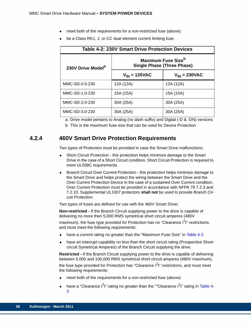
4.2.3 230V Smart Drive Protection RequirementsTwo types of Protection must be provided in case the Smart Drive malfunctions:
• Short Circuit Protection - this protection helps minimize damage to the Smart Drive in the case of a Short Circuit condition. Short Circuit Protection is required to meet UL508C requirements.
• Branch Circuit Over Current Protection - this protection helps minimize damage to the Smart Drive and helps protect the wiring between the Smart Drive and the Over Current Protection Device in the case of a sustained Over Current condition. Over Current Protection must be provided in accordance with NFPA 79 7.2.3 and 7.2.10. Supplemental UL1007 protectors shall not be used to provide Branch Cir-cuit Protection.
When using the 230V Smart Drive, the fuse that provides Short Circuit Protection also provides Over Current Circuit Protection, therefore a separate Short Circuit Protection fuse is not required.
Two types of fuses are defined for use with the 230V Smart Drive:
Non-restricted - If the Branch Circuit supplying power to the drive is capable of delivering no more then 5,000 RMS symetrical short circuit amperes (240V maximum), the fuse type provided for Protection has no “Clearance I2t” restrictions, and must meet the following requirements:
• have a current rating no greater than the “Maximum Fuse Size” in Table 4-2
• have an interrupt capability no less than the short circuit rating (Prospective Short-circuit Symetrical Amperes) of the Branch Circuit supplying the drive.
Restricted - If the Branch Circuit supplying power to the drive is capable of delivering between 5,000 and 100,000 RMS symetrical short circuit amperes (240V maximum), the fuse type provided for Protection has “Clearance I2t” restrictions, and must meet the following requirements:
Kollmorgen - March 2011 37
38
MMC Smart Drive Hardware Manual - SYSTEM POWER DEVICES
• meet both of the requirements for a non-restricted fuse (above)
• be a Class RK1, J, or CC dual element current limiting fuse
4.2.4 460V Smart Drive Protection RequirementsTwo types of Protection must be provided in case the Smart Drive malfunctions:
• Short Circuit Protection - this protection helps minimize damage to the Smart Drive in the case of a Short Circuit condition. Short Circuit Protection is required to meet UL508C requirements.
• Branch Circuit Over Current Protection - this protection helps minimize damage to the Smart Drive and helps protect the wiring between the Smart Drive and the Over Current Protection Device in the case of a sustained Over Current condition. Over Current Protection must be provided in accordance with NFPA 79 7.2.3 and 7.2.10. Supplemental UL1007 protectors shall not be used to provide Branch Cir-cuit Protection.
Two types of fuses are defined for use with the 460V Smart Drive:
Non-restricted - If the Branch Circuit supplying power to the drive is capable of delivering no more then 5,000 RMS symetrical short circuit amperes (480V maximum), the fuse type provided for Protection has no “Clearance I2t” restrictions, and must meet the following requirements:
• have a current rating no greater than the “Maximum Fuse Size” in Table 4-3
• have an interrupt capability no less than the short circuit rating (Prospective Short-circuit Symetrical Amperes) of the Branch Circuit supplying the drive.
Restricted - If the Branch Circuit supplying power to the drive is capable of delivering between 5,000 and 100,000 RMS symetrical short circuit amperes (480V maximum), the fuse type provided for Protection has “Clearance I2t” restrictions, and must meet the following requirements:
• meet both of the requirements for a non-restricted fuse (above)
• have a “Clearance I2t” rating no greater than the “”Clearance I2t” rating in Table 4-3
Table 4-2: 230V Smart Drive Protection Devices
230V Drive Modela
a. Drive model pertains to Analog (no dash suffix) and Digital (-D & -DN) versions
Maximum Fuse Sizeb
Single Phase (Three Phase)
b. This is the maximum fuse size that can be used for Device Protection
VIN = 120VAC VIN = 230VAC
MMC-SD-0.5-230 12A (12A) 12A (12A)
MMC-SD-1.0-230 15A (15A) 15A (15A)
MMC-SD-2.0-230 30A (25A) 30A (25A)
MMC-SD-3.0-230 30A (25A) 30A (25A)
Kollmorgen - March 2011

MMC Smart Drive Hardware Manual - SYSTEM POWER DEVICES
The requirements for both restricted and non restricted fuses may be meet by using one of two methods:
• Use a single fuse that meets all requirements. The easiest way to accomplish this is to use a “Combination Fuse” from Table 4-3. These fuses meet all of the requirements for both Short Circuit Protection and Over Current Protection, and may be used on Branch Circuits that supply up to 100,000 RMS symetrical short circuit amperes (480V maximum).
• Use two fuses connected in series, that, in combination, meet all of the require-ments:
• Use an Over Current Protection fuse that has a current rating not greater than the “Maximum Fuse Size” shown in Table 4-3, and an interrupt capability not less than the short circuit rating (Prospective Short-circuit Symetrical Amperes) of the Branch Circuit supplying the drive.
• Use a Short circuit Protection fuse (typically a semiconductor fuse) that has a “Clearance I2t” rating not greater than that shown in Table 4-3, and a current rating greater than the Over Current Protection fuse (to avoid nuisance trip-ping).
See Table 4-4 on page 41 to for a listing of available fuses and fuse holders from Kollmorgen.
Kollmorgen - March 2011 39
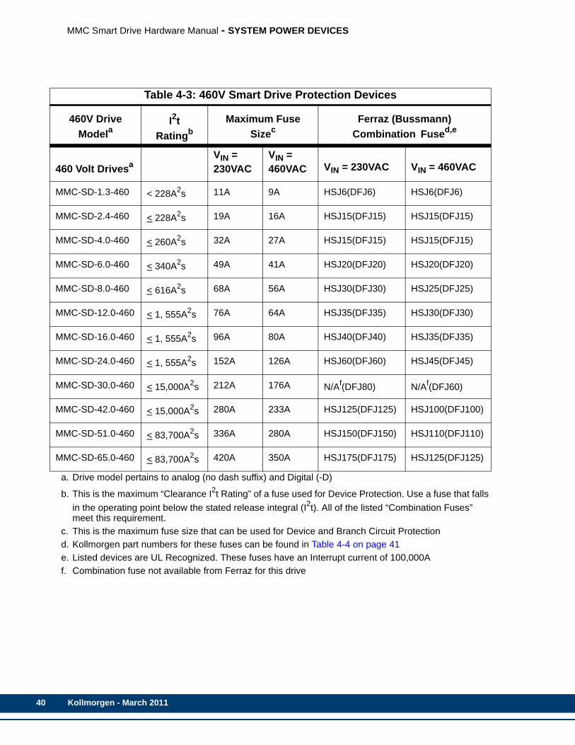
40
MMC Smart Drive Hardware Manual - SYSTEM POWER DEVICES
4
M
M
M
M
M
M
M
M
M
M
M
M
Table 4-3: 460V Smart Drive Protection Devices
460V Drive Modela
a. Drive model pertains to analog (no dash suffix) and Digital (-D)
I2t Ratingb
b. This is the maximum “Clearance I2t Rating” of a fuse used for Device Protection. Use a fuse that falls in the operating point below the stated release integral (I2t). All of the listed “Combination Fuses” meet this requirement.
Maximum Fuse Sizec
c. This is the maximum fuse size that can be used for Device and Branch Circuit Protection
Ferraz (Bussmann) Combination Fused,e
d. Kollmorgen part numbers for these fuses can be found in Table 4-4 on page 41e. Listed devices are UL Recognized. These fuses have an Interrupt current of 100,000A
60 Volt DrivesaVIN = 230VAC
VIN = 460VAC VIN = 230VAC VIN = 460VAC
MC-SD-1.3-460 < 228A2s 11A 9A HSJ6(DFJ6) HSJ6(DFJ6)
MC-SD-2.4-460 < 228A2s 19A 16A HSJ15(DFJ15) HSJ15(DFJ15)
MC-SD-4.0-460 < 260A2s 32A 27A HSJ15(DFJ15) HSJ15(DFJ15)
MC-SD-6.0-460 < 340A2s 49A 41A HSJ20(DFJ20) HSJ20(DFJ20)
MC-SD-8.0-460 < 616A2s 68A 56A HSJ30(DFJ30) HSJ25(DFJ25)
MC-SD-12.0-460 < 1, 555A2s 76A 64A HSJ35(DFJ35) HSJ30(DFJ30)
MC-SD-16.0-460 < 1, 555A2s 96A 80A HSJ40(DFJ40) HSJ35(DFJ35)
MC-SD-24.0-460 < 1, 555A2s 152A 126A HSJ60(DFJ60) HSJ45(DFJ45)
MC-SD-30.0-460 < 15,000A2s 212A 176A N/Af(DFJ80)
f. Combination fuse not available from Ferraz for this drive
N/Af(DFJ60)
MC-SD-42.0-460 < 15,000A2s 280A 233A HSJ125(DFJ125) HSJ100(DFJ100)
MC-SD-51.0-460 < 83,700A2s 336A 280A HSJ150(DFJ150) HSJ110(DFJ110)
MC-SD-65.0-460 < 83,700A2s 420A 350A HSJ175(DFJ175) HSJ125(DFJ125)
Kollmorgen - March 2011
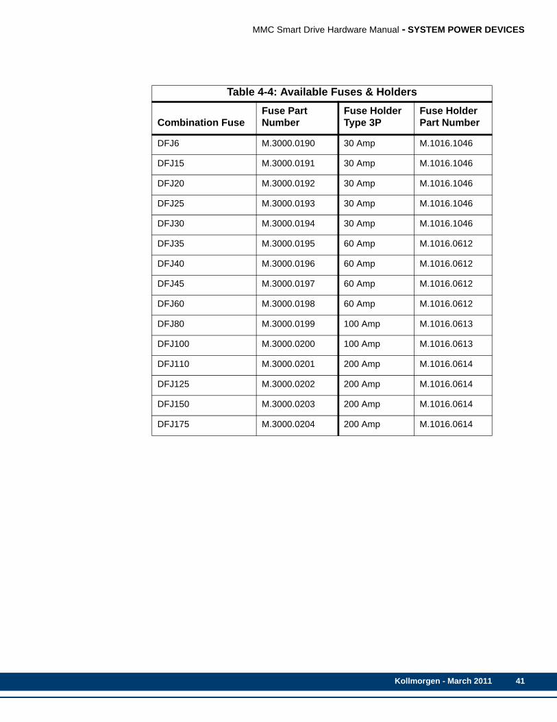
MMC Smart Drive Hardware Manual - SYSTEM POWER DEVICES
Table 4-4: Available Fuses & Holders
Combination FuseFuse Part Number
Fuse Holder Type 3P
Fuse Holder Part Number
DFJ6 M.3000.0190 30 Amp M.1016.1046
DFJ15 M.3000.0191 30 Amp M.1016.1046
DFJ20 M.3000.0192 30 Amp M.1016.1046
DFJ25 M.3000.0193 30 Amp M.1016.1046
DFJ30 M.3000.0194 30 Amp M.1016.1046
DFJ35 M.3000.0195 60 Amp M.1016.0612
DFJ40 M.3000.0196 60 Amp M.1016.0612
DFJ45 M.3000.0197 60 Amp M.1016.0612
DFJ60 M.3000.0198 60 Amp M.1016.0612
DFJ80 M.3000.0199 100 Amp M.1016.0613
DFJ100 M.3000.0200 100 Amp M.1016.0613
DFJ110 M.3000.0201 200 Amp M.1016.0614
DFJ125 M.3000.0202 200 Amp M.1016.0614
DFJ150 M.3000.0203 200 Amp M.1016.0614
DFJ175 M.3000.0204 200 Amp M.1016.0614
Kollmorgen - March 2011 41
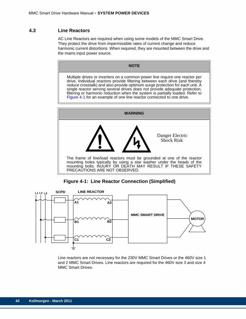
42
MMC Smart Drive Hardware Manual - SYSTEM POWER DEVICES
4.3 Line ReactorsAC Line Reactors are required when using some models of the MMC Smart Drive. They protect the drive from impermissible rates of current change and reduce harmonic current distortions. When required, they are mounted between the drive and the mains input power source.
Figure 4-1: Line Reactor Connection (Simplified)
Line reactors are not necessary for the 230V MMC Smart Drives or the 460V size 1 and 2 MMC Smart Drives. Line reactors are required for the 460V size 3 and size 4 MMC Smart Drives.
NOTE
Multiple drives or inverters on a common power line require one reactor perdrive. Individual reactors provide filtering between each drive (and therebyreduce crosstalk) and also provide optimum surge protection for each unit. Asingle reactor serving several drives does not provide adequate protection,filtering or harmonic reduction when the system is partially loaded. Refer toFigure 4-1 for an example of one line reactor connected to one drive.
WARNING
The frame of line/load reactors must be grounded at one of the reactormounting holes typically by using a star washer under the heads of themounting bolts. INJURY OR DEATH MAY RESULT IF THESE SAFETYPRECAUTIONS ARE NOT OBSERVED.
Danger Electric Shock Risk
MOTOR
C1 C2
B1 B2
A1 A2
MMC SMART DRIVE
LINE REACTORSCPDL1 L2 L3
Kollmorgen - March 2011
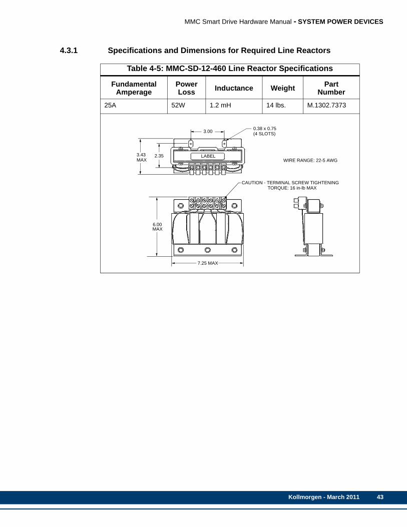
MMC Smart Drive Hardware Manual - SYSTEM POWER DEVICES
4.3.1 Specifications and Dimensions for Required Line Reactors
Table 4-5: MMC-SD-12-460 Line Reactor Specifications
Fundamental Amperage
PowerLoss Inductance Weight Part
Number
25A 52W 1.2 mH 14 lbs. M.1302.7373
7.25 MAX
2.353.43
0.38 x 0.75(4 SLOTS)
LABELWIRE RANGE: 22-5 AWG
CAUTION - TERMINAL SCREW TIGHTENING TORQUE: 16 in-lb MAX
6.00MAX
3.00
MAX
Kollmorgen - March 2011 43
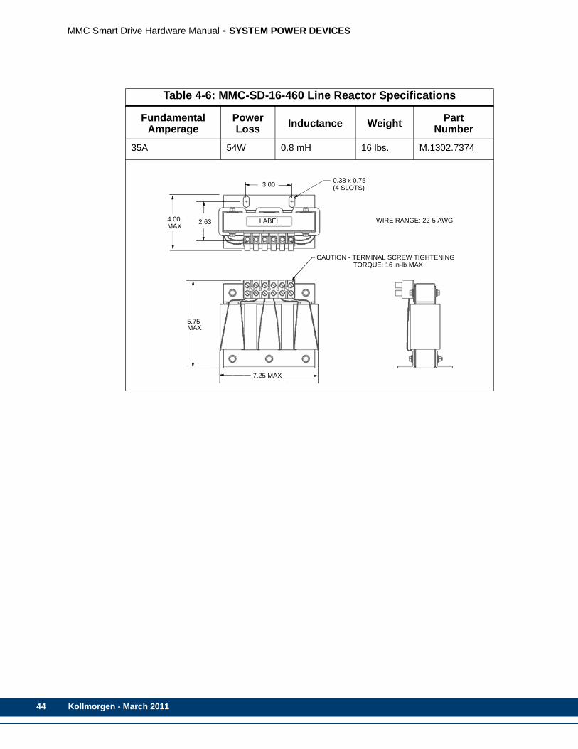
44
MMC Smart Drive Hardware Manual - SYSTEM POWER DEVICES
Table 4-6: MMC-SD-16-460 Line Reactor Specifications
Fundamental Amperage
PowerLoss Inductance Weight Part
Number
35A 54W 0.8 mH 16 lbs. M.1302.7374
7.25 MAX
2.634.00
0.38 x 0.75(4 SLOTS)
LABEL WIRE RANGE: 22-5 AWG
CAUTION - TERMINAL SCREW TIGHTENING TORQUE: 16 in-lb MAX
5.75MAX
3.00
MAX
Kollmorgen - March 2011
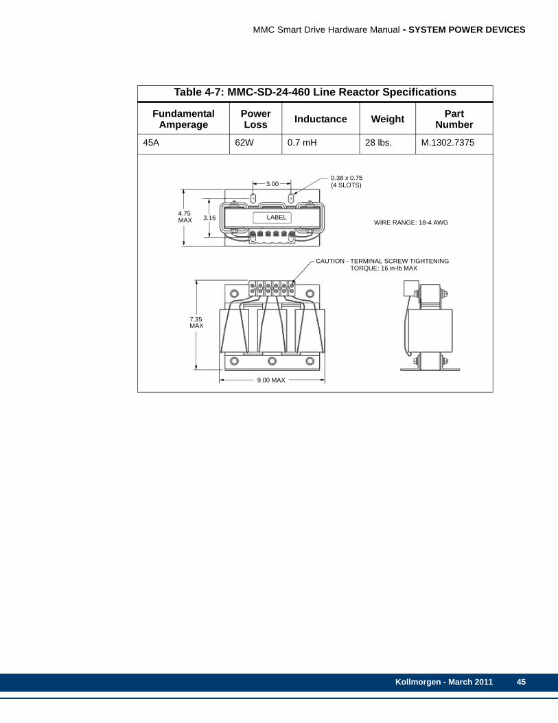
MMC Smart Drive Hardware Manual - SYSTEM POWER DEVICES
Table 4-7: MMC-SD-24-460 Line Reactor Specifications
Fundamental Amperage
PowerLoss Inductance Weight Part
Number
45A 62W 0.7 mH 28 lbs. M.1302.7375
9.00 MAX
3.164.75
0.38 x 0.75(4 SLOTS)
LABELWIRE RANGE: 18-4 AWG
CAUTION - TERMINAL SCREW TIGHTENING TORQUE: 16 in-lb MAX
7.35MAX
3.00
MAX
Kollmorgen - March 2011 45

46
MMC Smart Drive Hardware Manual - SYSTEM POWER DEVICES
Table 4-8: MMC-SD-30-460 Line Reactor Specifications
Fundamental Amperage
PowerLoss Inductance Weight Part
Number
55A 67W 0.5 mH 27 lbs. M.3000.0105
Kollmorgen - March 2011
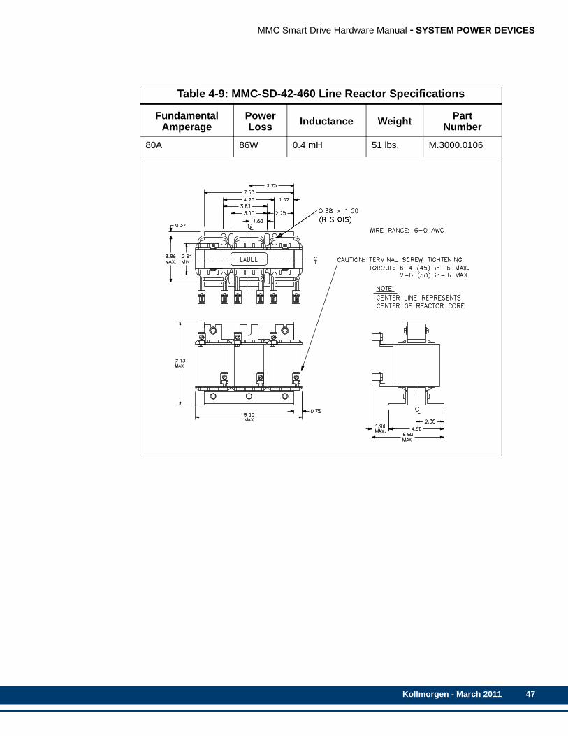
MMC Smart Drive Hardware Manual - SYSTEM POWER DEVICES
Table 4-9: MMC-SD-42-460 Line Reactor Specifications
Fundamental Amperage
PowerLoss Inductance Weight Part
Number
80A 86W 0.4 mH 51 lbs. M.3000.0106
Kollmorgen - March 2011 47
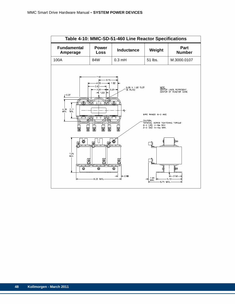
48
MMC Smart Drive Hardware Manual - SYSTEM POWER DEVICES
Table 4-10: MMC-SD-51-460 Line Reactor Specifications
Fundamental Amperage
PowerLoss Inductance Weight Part
Number
100A 84W 0.3 mH 51 lbs. M.3000.0107
Kollmorgen - March 2011
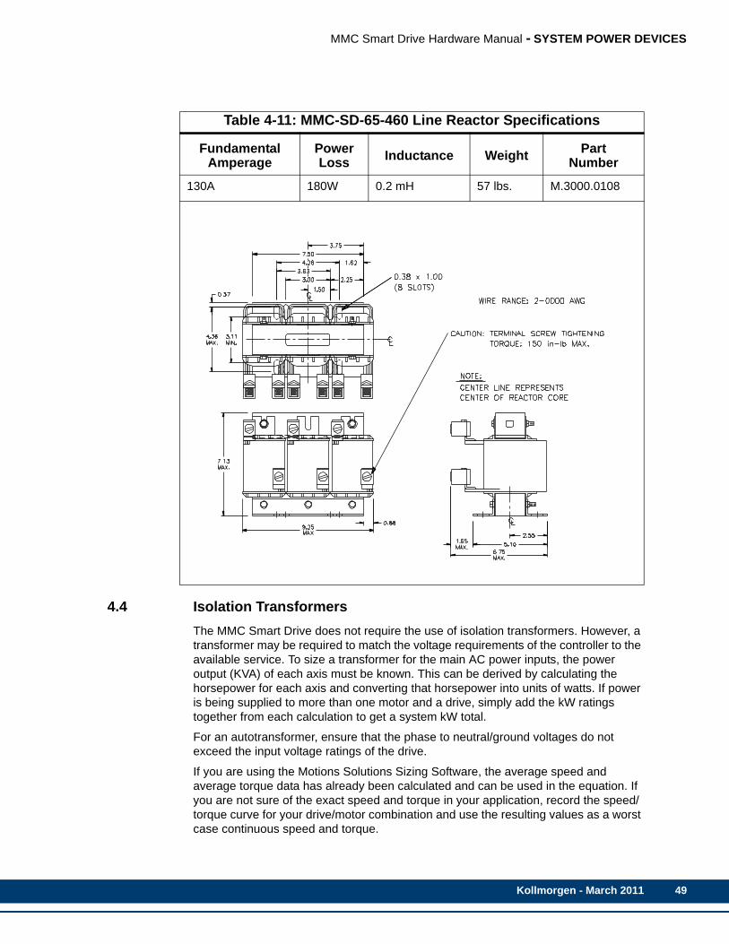
MMC Smart Drive Hardware Manual - SYSTEM POWER DEVICES
4.4 Isolation TransformersThe MMC Smart Drive does not require the use of isolation transformers. However, a transformer may be required to match the voltage requirements of the controller to the available service. To size a transformer for the main AC power inputs, the power output (KVA) of each axis must be known. This can be derived by calculating the horsepower for each axis and converting that horsepower into units of watts. If power is being supplied to more than one motor and a drive, simply add the kW ratings together from each calculation to get a system kW total.
For an autotransformer, ensure that the phase to neutral/ground voltages do not exceed the input voltage ratings of the drive.
If you are using the Motions Solutions Sizing Software, the average speed and average torque data has already been calculated and can be used in the equation. If you are not sure of the exact speed and torque in your application, record the speed/torque curve for your drive/motor combination and use the resulting values as a worst case continuous speed and torque.
Table 4-11: MMC-SD-65-460 Line Reactor Specifications
Fundamental Amperage
PowerLoss Inductance Weight Part
Number
130A 180W 0.2 mH 57 lbs. M.3000.0108
Kollmorgen - March 2011 49
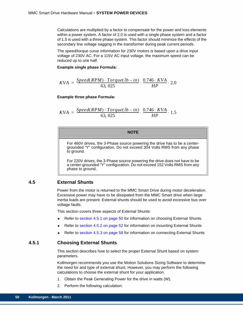
50
MMC Smart Drive Hardware Manual - SYSTEM POWER DEVICES
Calculations are multiplied by a factor to compensate for the power and loss elements within a power system. A factor of 2.0 is used with a single phase system and a factor of 1.5 is used with a three phase system. This factor should minimize the effects of the secondary line voltage sagging in the transformer during peak current periods.
The speed/torque curve information for 230V motors is based upon a drive input voltage of 230V AC. For a 115V AC input voltage, the maximum speed can be reduced up to one half.
Example single phase Formula:
Example three phase Formula:
4.5 External ShuntsPower from the motor is returned to the MMC Smart Drive during motor deceleration. Excessive power may have to be dissipated from the MMC Smart drive when large inertia loads are present. External shunts should be used to avoid excessive bus over voltage faults.
This section covers three aspects of External Shunts:
• Refer to section 4.5.1 on page 50 for information on choosing External Shunts.
• Refer to section 4.5.2 on page 52 for information on mounting External Shunts
• Refer to section 4.5.3 on page 58 for information on connecting External Shunts
4.5.1 Choosing External ShuntsThis section describes how to select the proper External Shunt based on system parameters.
Kollmorgen recommends you use the Motion Solutions Sizing Software to determine the need for and type of external shunt. However, you may perform the following calculations to choose the external shunt for your application.
1. Obtain the Peak Generating Power for the drive in watts (W).
2. Perform the following calculation:
NOTE
For 460V drives, the 3-Phase source powering the drive has to be a center-grounded “Y” configuration. Do not exceed 304 Volts RMS from any phaseto ground.
For 220V drives, the 3-Phase source powering the drive does not have to bea center-grounded “Y” configuration. Do not exceed 152 Volts RMS from anyphase to ground.
KVA Speed RPM( ) Torque lb in–( )⋅63 025,
------------------------------------------------------------------------------ 0.746 KVA⋅HP
------------------------------ 2.0⋅ ⋅=
KVA Speed RPM( ) Torque lb in–( )⋅63 025,
------------------------------------------------------------------------------ 0.746 KVA⋅HP
------------------------------ 1.5⋅ ⋅=
Kollmorgen - March 2011
MMC Smart Drive Hardware Manual - SYSTEM POWER DEVICES
W x T = Watts/sec or Joules
where:
W is watts from Step 1 above,
T is decel time required by the application
3. Obtain the Absorption Energy in Joules for the drive from the Specifications sec-tion of the drive manual.
4. Determine the Peak Shunt Power from the drive that would be delivered to the shunt resistor for your application:
• (Number calculated in Step 2 above) - (Absorption Energy from the drive Specifications table in either Chapter 5 or 6)= Watt-seconds
• (Watt-seconds computed in 5a. above) (Decel Time for the application) = Peak Shunt Power in Watts
5. Determine the Continuous Shunt Power that would be delivered to the shunt resistor for this application:
• Duty Cycle of Peak or Peak x Decel Time) (Total Cycle Time) = Continuous Shunt Power in Watts
6. Choose an external shunt from Table 4-12.
Kollmorgen - March 2011 51
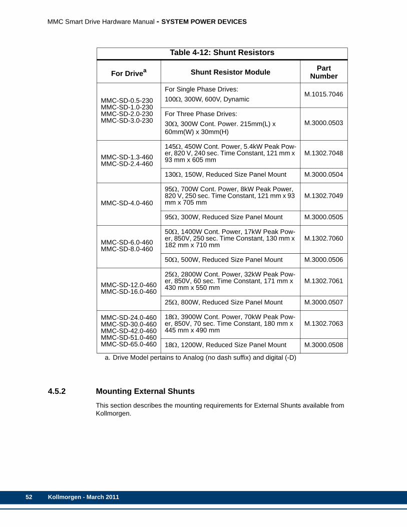
52
MMC Smart Drive Hardware Manual - SYSTEM POWER DEVICES
4.5.2 Mounting External ShuntsThis section describes the mounting requirements for External Shunts available from Kollmorgen.
Table 4-12: Shunt Resistors
For Drivea Shunt Resistor Module Part Number
MMC-SD-0.5-230MMC-SD-1.0-230MMC-SD-2.0-230MMC-SD-3.0-230
For Single Phase Drives:100Ω, 300W, 600V, Dynamic
M.1015.7046
For Three Phase Drives:30Ω, 300W Cont. Power. 215mm(L) x 60mm(W) x 30mm(H)
M.3000.0503
MMC-SD-1.3-460MMC-SD-2.4-460
145Ω, 450W Cont. Power, 5.4kW Peak Pow-er, 820 V, 240 sec. Time Constant, 121 mm x 93 mm x 605 mm
M.1302.7048
130Ω, 150W, Reduced Size Panel Mount M.3000.0504
MMC-SD-4.0-460
95Ω, 700W Cont. Power, 8kW Peak Power, 820 V, 250 sec. Time Constant, 121 mm x 93 mm x 705 mm
M.1302.7049
95Ω, 300W, Reduced Size Panel Mount M.3000.0505
MMC-SD-6.0-460MMC-SD-8.0-460
50Ω, 1400W Cont. Power, 17kW Peak Pow-er, 850V, 250 sec. Time Constant, 130 mm x 182 mm x 710 mm
M.1302.7060
50Ω, 500W, Reduced Size Panel Mount M.3000.0506
MMC-SD-12.0-460MMC-SD-16.0-460
25Ω, 2800W Cont. Power, 32kW Peak Pow-er, 850V, 60 sec. Time Constant, 171 mm x 430 mm x 550 mm
M.1302.7061
25Ω, 800W, Reduced Size Panel Mount M.3000.0507
MMC-SD-24.0-460MMC-SD-30.0-460MMC-SD-42.0-460MMC-SD-51.0-460MMC-SD-65.0-460
18Ω, 3900W Cont. Power, 70kW Peak Pow-er, 850V, 70 sec. Time Constant, 180 mm x 445 mm x 490 mm
M.1302.7063
18Ω, 1200W, Reduced Size Panel Mount M.3000.0508
a. Drive Model pertains to Analog (no dash suffix) and digital (-D)
Kollmorgen - March 2011
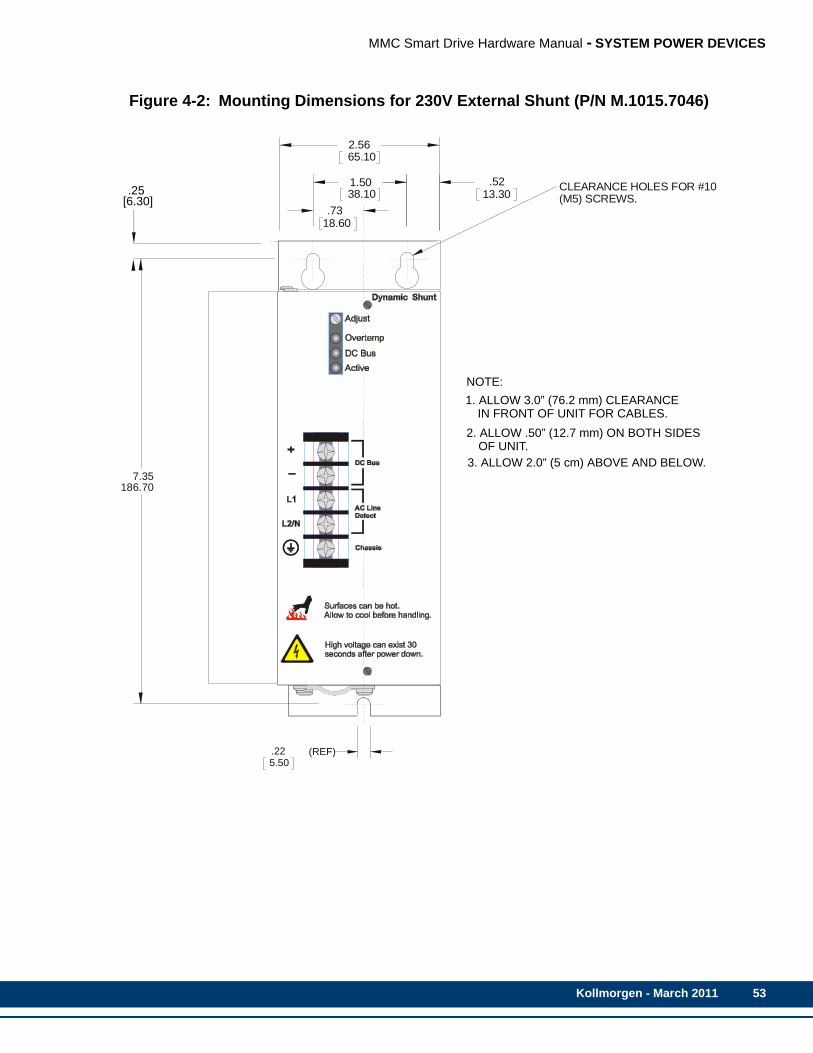
MMC Smart Drive Hardware Manual - SYSTEM POWER DEVICES
Figure 4-2: Mounting Dimensions for 230V External Shunt (P/N M.1015.7046)
2.5665.10
.7318.60
.5213.30
1.5038.10 CLEARANCE HOLES FOR #10
(M5) SCREWS.
NOTE:
1. ALLOW 3.0” (76.2 mm) CLEARANCE IN FRON UNIT FOR CABLES.
2. ALLOW .50” (12.7 mm) ON BOTH SIDES OF U
3. ALLOW 2.0” (5 cm) ABOVE AND BELOW
.225.50
(REF)
7.35186.70
.256.30
.25[6.30]
NOTE:1. ALLOW 3.0” (76.2 mm) CLEARANCE IN FRONT OF UNIT FOR CABLES.2. ALLOW .50” (12.7 mm) ON BOTH SIDES
OF UNIT.3. ALLOW 2.0” (5 cm) ABOVE AND BELOW.
Kollmorgen - March 2011 53

54
MMC Smart Drive Hardware Manual - SYSTEM POWER DEVICES
Figure 4-3: Mounting Dimensions for 460V External Shunt (P/N M.1302.7048)
Figure 4-4: Mounting Dimensions for 460V External Shunt (P/N M.1302.7049)
Figure 4-5: Mounting Dimensions for 460V External Shunt (P/N M.1302.7060)
2.52 in. (64 mm)
3.66 in. (93 mm)
4.7
6 in
. (12
1 m
m)
20.71 in. (526 mm)
23.82 in. (605 mm)
0 5, 5 x 8
2.52 in. (64 mm)
3.66 in. (93 mm)
4.7
6 in
. (12
1 m
m)
24.65 in. (626 mm)
27.76 in. (705 mm)
0 5, 5 x 8
5.90 in. (150 mm)
7.28 in. (185 mm)
5.1
2 in
. (13
0 m
m)
20.71 in. (526 mm)
23.82 in. (605 mm)
0 5, 5 x 8
Kollmorgen - March 2011
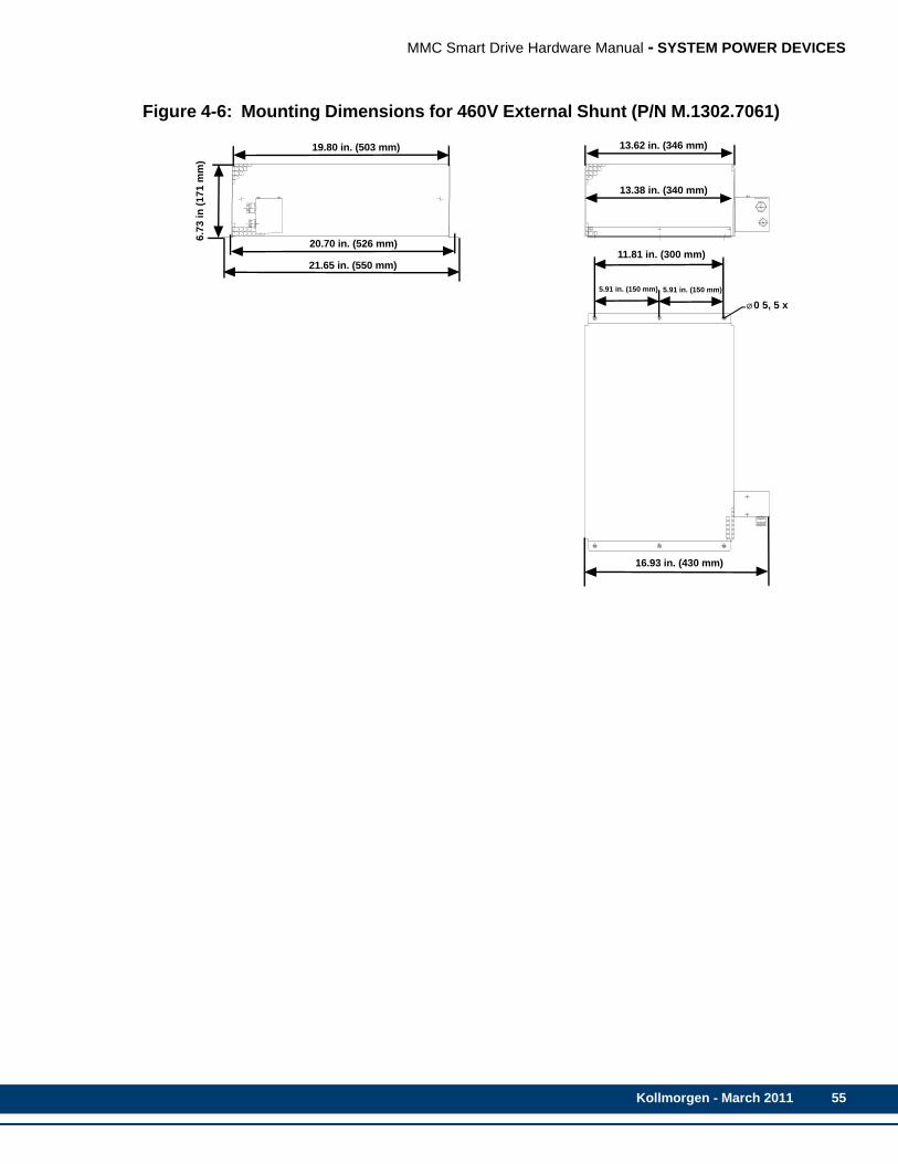
MMC Smart Drive Hardware Manual - SYSTEM POWER DEVICES
Figure 4-6: Mounting Dimensions for 460V External Shunt (P/N M.1302.7061)
11.81 in. (300 mm)
5.91 in. (150 mm)
6.73
in (1
71 m
m)
20.70 in. (526 mm)
0 5, 5 x
19.80 in. (503 mm)
21.65 in. (550 mm)
13.62 in. (346 mm)
13.38 in. (340 mm)
5.91 in. (150 mm)
16.93 in. (430 mm)
Kollmorgen - March 2011 55
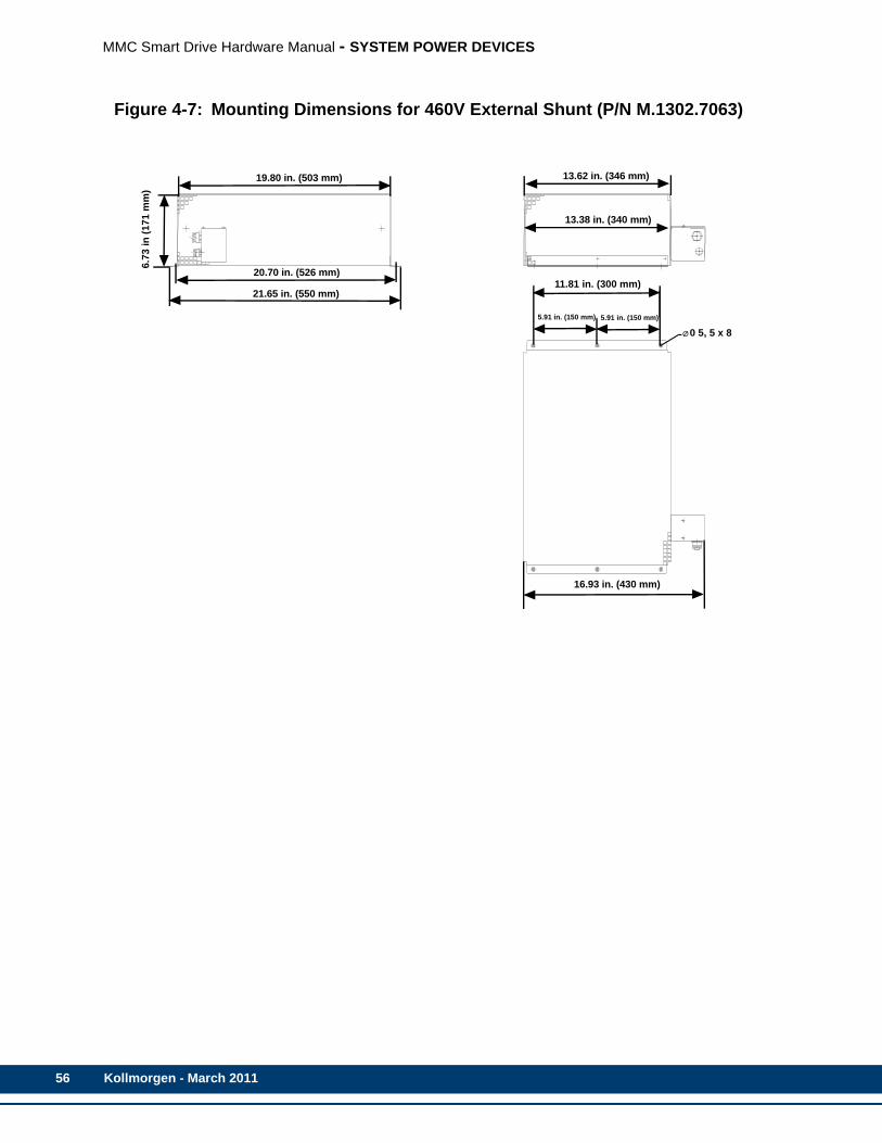
56
MMC Smart Drive Hardware Manual - SYSTEM POWER DEVICES
Figure 4-7: Mounting Dimensions for 460V External Shunt (P/N M.1302.7063)
11.81 in. (300 mm)
5.91 in. (150 mm)
6.73
in (1
71 m
m)
20.70 in. (526 mm)
0 5, 5 x 8
19.80 in. (503 mm)
21.65 in. (550 mm)
13.62 in. (346 mm)
13.38 in. (340 mm)
5.91 in. (150 mm)
16.93 in. (430 mm)
Kollmorgen - March 2011
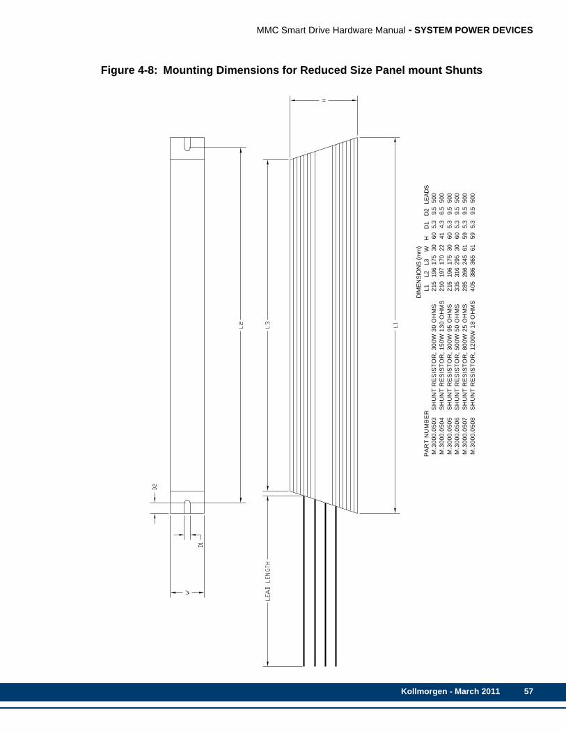
MMC Smart Drive Hardware Manual - SYSTEM POWER DEVICES
Figure 4-8: Mounting Dimensions for Reduced Size Panel mount Shunts
D
IME
NS
ION
S (m
m)
PA
RT
NU
MB
ER
L
1 L
2 L3 W
H
D
1 D
2 L
EA
DS
M.3
00
0.0
50
3
S
HU
NT
RE
SIS
TO
R,
30
0W
30
OH
MS
2
15 1
96 1
75 3
0 60 5
.3 9.5
5
00
M.3
00
0.0
50
4
S
HU
NT
RE
SIS
TO
R,
15
0W
13
0 O
HM
S
2
10 1
97 1
70 2
2 41 4
.3 6.5
5
00
M.3
00
0.0
50
5
S
HU
NT
RE
SIS
TO
R,
30
0W
95
OH
MS
2
15 1
96 1
75 3
0 60 5
.3 9.5
5
00
M.3
00
0.0
50
6
S
HU
NT
RE
SIS
TO
R,
50
0W
50
OH
MS
3
35 3
16 2
95 3
0 60 5
.3 9.5
5
00
M.3
00
0.0
50
7
S
HU
NT
RE
SIS
TO
R,
80
0W
25
OH
MS
2
85 2
66 2
45 6
1 59 5
.3 9.5
5
00
M.3
00
0.0
50
8
S
HU
NT
RE
SIS
TO
R,
12
00
W 1
8 O
HM
S
4
05 3
86 3
65 6
1 59 5
.3 9.5
5
00
Kollmorgen - March 2011 57

58
MMC Smart Drive Hardware Manual - SYSTEM POWER DEVICES
4.5.3 Connecting Shunt ModulesThis section describes how to connect External Shunts to the drive.
Use shielded, high temperature 75° C (167° F), 600V, 2.5-4.0 mm2 (12-14 AWG), 3.05 m (10 ft) maximum, copper wire. Follow one of the methods given below to reduce the effects of EMI noise:
• Install wires using twisted pairs (two turns per foot minimum), as shown in the fig-ure below. Keep unshielded wires as short as possible.
• Use shielded, twisted cable (ground shield at shunt and drive).
• Use shielded metal conduit (ground conduit at shunt and drive).
When two shunt modules are connected in parallel, the shunt capacity is doubled.
4.5.3.1 230V, 1-Phase MMC Smart Drive Shunt WiringThe 230V, 1-Phase MMC Smart Drive requires the use of an Active Shunt module. Refer to Figure 4-9 for wiring an Active Shunt Module to this drive.
The 230V, 3-Phase MMC Smart Drive requires the use of a Passive Shunt module (regen resistor). Refer to Figure 4-10 for wiring an Passive Shunt Module to this drive.
WARNING
Do not connect more than two shunt modules to an MMC Smart Drive.
Kollmorgen - March 2011
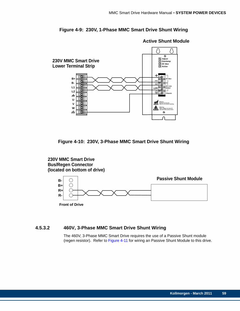
MMC Smart Drive Hardware Manual - SYSTEM POWER DEVICES
Figure 4-9: 230V, 1-Phase MMC Smart Drive Shunt Wiring
Figure 4-10: 230V, 3-Phase MMC Smart Drive Shunt Wiring
4.5.3.2 460V, 3-Phase MMC Smart Drive Shunt WiringThe 460V, 3-Phase MMC Smart Drive requires the use of a Passive Shunt module (regen resistor). Refer to Figure 4-11 for wiring an Passive Shunt Module to this drive.
AdjustOvertempDC BusActive
AC Line
Chassis
DC Bus
Active Shunt Module
Detect
Warning:High voltage can exist 30seconds after power down.
Warning:Surfaces can be hot.Allow to cool before handling.
230V MMC Smart DriveLower Terminal Strip
L1
L2/N
WVU
L2L1B-B+
230V MMC Smart DriveBus/Regen Connector
B-B+
R-R+
Front of Drive
(located on bottom of drive)
Passive Shunt Module
Kollmorgen - March 2011 59
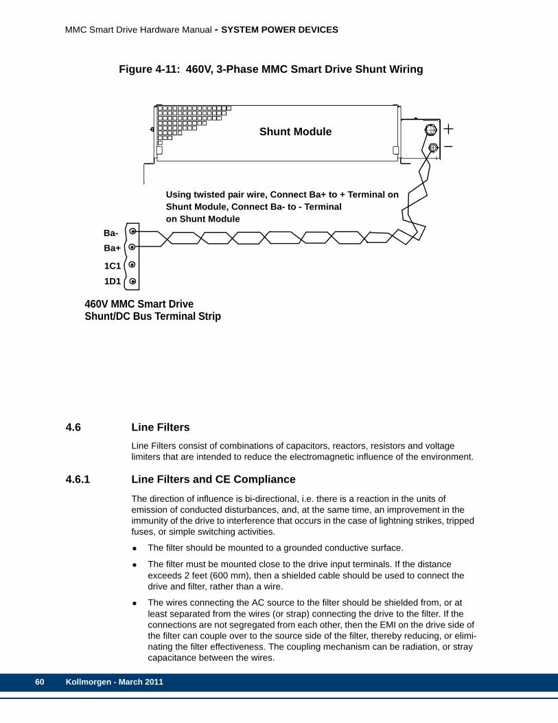
60
MMC Smart Drive Hardware Manual - SYSTEM POWER DEVICES
Figure 4-11: 460V, 3-Phase MMC Smart Drive Shunt Wiring
4.6 Line FiltersLine Filters consist of combinations of capacitors, reactors, resistors and voltage limiters that are intended to reduce the electromagnetic influence of the environment.
4.6.1 Line Filters and CE ComplianceThe direction of influence is bi-directional, i.e. there is a reaction in the units of emission of conducted disturbances, and, at the same time, an improvement in the immunity of the drive to interference that occurs in the case of lightning strikes, tripped fuses, or simple switching activities.
• The filter should be mounted to a grounded conductive surface.
• The filter must be mounted close to the drive input terminals. If the distance exceeds 2 feet (600 mm), then a shielded cable should be used to connect the drive and filter, rather than a wire.
• The wires connecting the AC source to the filter should be shielded from, or at least separated from the wires (or strap) connecting the drive to the filter. If the connections are not segregated from each other, then the EMI on the drive side of the filter can couple over to the source side of the filter, thereby reducing, or elimi-nating the filter effectiveness. The coupling mechanism can be radiation, or stray capacitance between the wires.
Shunt Module
460V MMC Smart DriveShunt/DC Bus Terminal Strip
Ba-Ba+
1C11D1
Using twisted pair wire, Connect Ba+ to + Terminal onShunt Module, Connect Ba- to - Terminalon Shunt Module
Kollmorgen - March 2011
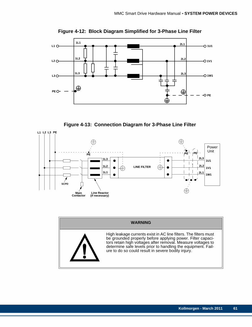
MMC Smart Drive Hardware Manual - SYSTEM POWER DEVICES
Figure 4-12: Block Diagram Simplified for 3-Phase Line Filter
Figure 4-13: Connection Diagram for 3-Phase Line Filter
WARNING
High leakage currents exist in AC line filters. The filters mustbe grounded properly before applying power. Filter capaci-tors retain high voltages after removal. Measure voltages todetermine safe levels prior to handling the equipment. Fail-ure to do so could result in severe bodily injury.
1L1
1L2
1L3
L1
L2
L3
PE
2L1
2L2
2L3
1U1
1V1
1W1
PE
Line Reactor(if necessary)
PowerUnit
PE PEPE
1L1
1L2
1L3
MainContactor
LINE FILTER
2L1
2L2
2L3
PEL3L2L1
1U1
1V1
1W1
SCPD
Kollmorgen - March 2011 61

62
MMC Smart Drive Hardware Manual - SYSTEM POWER DEVICES
NOTE
To be able to route the interference currents at low impedance back tothe interference sources, the filter, the power unit, and the contact areaof the motor cable shield must have a junction with the common mount-ing plate over as wide a surface as possible that has good conductiveproperties. The best way to ensure this is to use unpainted zinc-coatedmounting plates.
Table 4-13: Part Numbers for AC Line Filters
Current For Drive Part Number
6A, 250V, 1 PhaseSingle Phase Versions of:MMC-SD-0.5-230MMC-SD-1.0-230
M.1015.6922
10A, 250V, 1 PhaseSingle Phase Versions of:MMC-SD-2.0-230MMC-SD-3.0-230
M.1015.6917
16A, 480V, 3 Phase
Three Phase Versions of:MMC-SD-0.5-230MMC-SD-1.0-230MMC-SD-2.0-230MMC-SD-3.0-230
M.1302.5244
7A, 480V, 3 Phase MMC-SD-1.3-460MMC-SD-2.4-460 M.1302.5241
16A, 480V, 3 PhaseMMC-SD-4.0-460MMC-SD-6.0-460MMC-SD-8.0-460
M.1302.5244
30A, 480V, 3 Phase MMC-SD-12.0-460MMC-SD-16.0-460 M.1302.5245
42A, 480V, 3 Phase MMC-SD-24.0-460 M.1302.5246
56A, 480V, 3 Phase MMC-SD-30.0-460MMC-SD-42.0-460 M.1302.5247
75A, 480V, 3 Phase MMC-SD-51.0-460 M.1302.5248
100A, 480V, 3 Phase MMC-SD-65.0-460 M.3000.0109
Kollmorgen - March 2011
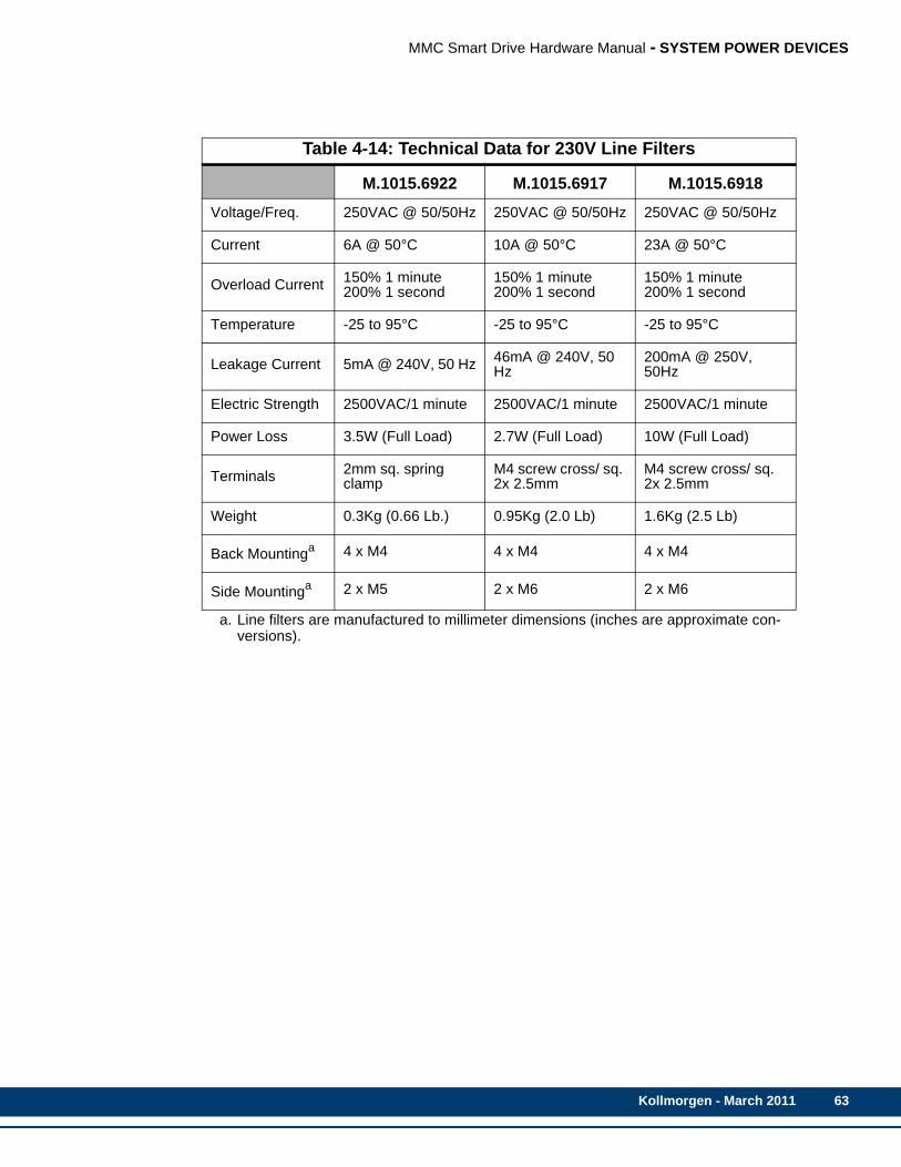
MMC Smart Drive Hardware Manual - SYSTEM POWER DEVICES
Table 4-14: Technical Data for 230V Line Filters
M.1015.6922 M.1015.6917 M.1015.6918
Voltage/Freq. 250VAC @ 50/50Hz 250VAC @ 50/50Hz 250VAC @ 50/50Hz
Current 6A @ 50°C 10A @ 50°C 23A @ 50°C
Overload Current 150% 1 minute200% 1 second
150% 1 minute200% 1 second
150% 1 minute200% 1 second
Temperature -25 to 95°C -25 to 95°C -25 to 95°C
Leakage Current 5mA @ 240V, 50 Hz 46mA @ 240V, 50 Hz
200mA @ 250V, 50Hz
Electric Strength 2500VAC/1 minute 2500VAC/1 minute 2500VAC/1 minute
Power Loss 3.5W (Full Load) 2.7W (Full Load) 10W (Full Load)
Terminals 2mm sq. spring clamp
M4 screw cross/ sq. 2x 2.5mm
M4 screw cross/ sq. 2x 2.5mm
Weight 0.3Kg (0.66 Lb.) 0.95Kg (2.0 Lb) 1.6Kg (2.5 Lb)
Back Mountinga
a. Line filters are manufactured to millimeter dimensions (inches are approximate con-versions).
4 x M4 4 x M4 4 x M4
Side Mountinga 2 x M5 2 x M6 2 x M6
Kollmorgen - March 2011 63
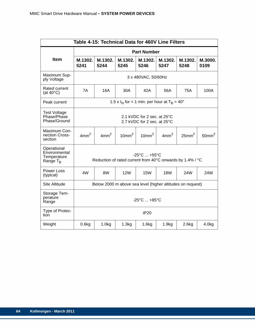
64
MMC Smart Drive Hardware Manual - SYSTEM POWER DEVICES
Table 4-15: Technical Data for 460V Line Filters
ItemPart Number
M.1302.5241
M.1302.5244
M.1302.5245
M.1302.5246
M.1302.5247
M.1302.5248
M.3000.0109
Maximum Sup-ply Voltage 3 x 480VAC, 50/60Hz
Rated current(at 40°C) 7A 16A 30A 42A 56A 75A 100A
Peak current 1.5 x IN for < 1 min. per hour at TB = 40°
Test VoltagePhase/PhasePhase/Ground
2.1 kVDC for 2 sec. at 25°C2.7 kVDC for 2 sec. at 25°C
Maximum Con-nection Cross-section
4mm2 4mm2 10mm2 10mm2 4mm2 25mm2 50mm2
Operational Environmental Temperature Range TB
-25°C ... +55°CReduction of rated current from 40°C onwards by 1.4% / °C
Power Loss (typical) 4W 8W 12W 15W 18W 24W 24W
Site Altitude Below 2000 m above sea level (higher altitudes on request)
Storage Tem-perature Range -25°C ... +85°C
Type of Protec-tion IP20
Weight 0.6kg 1.0kg 1.3kg 1.6kg 1.9kg 2.6kg 4.0kg
Kollmorgen - March 2011

MMC Smart Drive Hardware Manual - SYSTEM POWER DEVICES
4.6.2 Dimensions for 230V Line Filters
SINGLE PHASE6A
M.1015.6922
SINGLE PHASE10A
M.1015.6917
SINGLE PHASE23A
M.1015.6918
MEASUREMENT mm in mm in mm in
A 170 6.7 214 8.4 214 8.4
A1 152 6.0 192 7.6 192 7.6
A2 9 0.4 11 0.4 11 0.4
B 92 3.6 145 5.7 204 8.0
B1 55 2.2 104 4.1 164 6.6
B2 18 0.7 20 0.8 20 0.8
C 25 1.0 40 1.6 47 1.8
C1 10 0.4 16 0.6 19 0.8
NOTE: Spring clips replaceTerminal screws on 6 Amp Filter (P/N 401-30222-00)
BB1
B2
AA1
CC1
A2
Kollmorgen - March 2011 65

66
MMC Smart Drive Hardware Manual - SYSTEM POWER DEVICES
4.6.3 Dimensions for 460V Line Filters
Part Number A B C D E F L G H
M.1302.5241 190 40 70 20 180 160 185
5.4
M5M.1302.5244 250 50 70 25 235 220 245
M.1302.5245 270 50 85 30 255 240 265
M.1302.5246 310 50 85 30 295 280 305
M6M.1302.5247 250 85 90 60 235 220 258
M.1302.5248 270 80 135 60 255 240 278 6.5
M.3000.0190 270 90 150 65 255 240 326 6.5 M10
Kollmorgen - March 2011

MMC Smart Drive Hardware Manual - 230V 1/3 PHASE MMC SMART DRIVE
5 230V 1/3 Phase MMC Smart DriveThe following 230V MMC Smart Drive are available:
• Single Phase analog and digital interfaced versions, with power ratings of .5kW, 1kW, and 2kW.
• Three Phase analog and digital interfaced versions, with power ratings of .5kW, 1kW, 2kW, 3kW (digital interfaced only).
This section describes these drives in detail.
Kollmorgen - March 2011 67
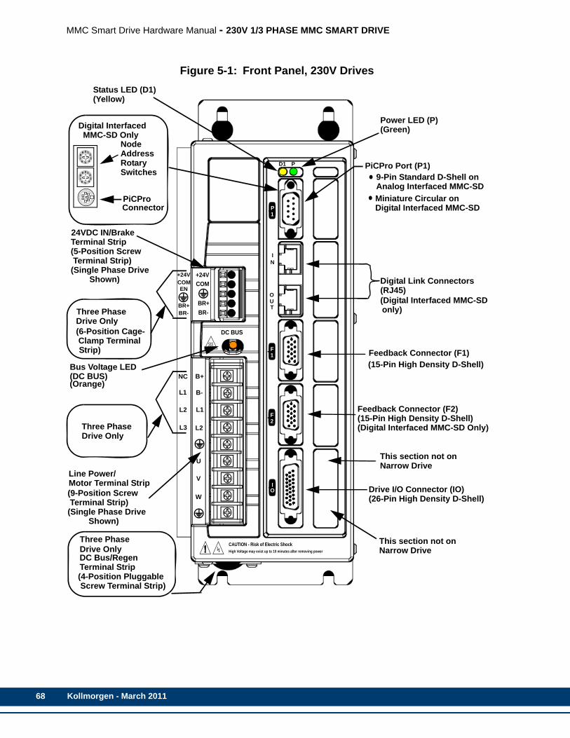
68
MMC Smart Drive Hardware Manual - 230V 1/3 PHASE MMC SMART DRIVE
Figure 5-1: Front Panel, 230V Drives
+24VCOM
BR+BR-
Feedback Connector (F1)
Drive I/O Connector (IO)(26-Pin High Density D-Shell)
CAUTION - Risk of Electric ShockHigh Voltage may exist up to 10 minutes after removing power
PiCPro Port (P1)
Line Power/
DC BUS
Motor Terminal Strip
9-Pin Standard D-Shell on
(15-Pin High Density D-Shell)
(9-Position Screw Terminal Strip)
W
V
U
L2
L1
B-
B+
P1
IN
OUT
F1
F2
IO
D1 P
Digital Link Connectors
(Digital Interfaced MMC-SD
123
4
87
6 5
9 0
123
4
87
6 5
9 0
NodeAddressRotary
PiCPro
Digital Interfaced
ConnectorMiniature Circular onDigital Interfaced MMC-SD
Analog Interfaced MMC-SD
only)
Switches
(RJ45)
MMC-SD Only
Feedback Connector (F2)(15-Pin High Density D-Shell)(Digital Interfaced MMC-SD Only)
This section not onNarrow Drive
Status LED (D1)(Yellow)
Power LED (P)(Green)
This section not onNarrow Drive
(Single Phase Drive Shown)
(4-Position Pluggable Screw Terminal Strip)
Three PhaseDrive Only
NC
L1
L2
L3Three PhaseDrive Only
+24VCOMEN
BR+BR-
(6-Position Cage- Clamp Terminal
Three PhaseDrive Only
24VDC IN/BrakeTerminal Strip(5-Position Screw Terminal Strip)
Bus Voltage LED(DC BUS)(Orange)
(Single Phase Drive Shown)
DC Bus/RegenTerminal Strip
Strip)
Kollmorgen - March 2011
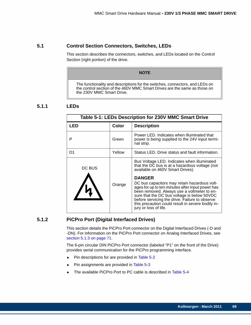
MMC Smart Drive Hardware Manual - 230V 1/3 PHASE MMC SMART DRIVE
5.1 Control Section Connectors, Switches, LEDsThis section describes the connectors, switches, and LEDs located on the Control Section (right portion) of the drive.
5.1.1 LEDs
5.1.2 PiCPro Port (Digital Interfaced Drives)This section details the PiCPro Port connector on the Digital Interfaced Drives (-D and -DN). For information on the PiCPro Port connector on Analog Interfaced Drives, see section 5.1.3 on page 71.
The 6-pin circular DIN PiCPro Port connector (labeled “P1” on the front of the Drive) provides serial communication for the PiCPro programming interface.
• Pin descriptions for are provided in Table 5-2
• Pin assignments are provided in Table 5-3
• The available PiCPro Port to PC cable is described in Table 5-4
NOTE
The functionality and descriptions for the switches, connectors, and LEDs onthe control section of the 460V MMC Smart Drives are the same as those onthe 230V MMC Smart Drive.
Table 5-1: LEDs Description for 230V MMC Smart DriveLED Color Description
P GreenPower LED. Indicates when illuminated that power is being supplied to the 24V input termi-nal strip.
D1 Yellow Status LED. Drive status and fault information.
DC BUS
Orange
Bus Voltage LED. Indicates when illuminated that the DC bus is at a hazardous voltage (not available on 460V Smart Drives).
DANGERDC bus capacitors may retain hazardous volt-ages for up to ten minutes after input power has been removed. Always use a voltmeter to en-sure that the DC bus voltage is below 50VDC before servicing the drive. Failure to observe this precaution could result in severe bodily in-jury or loss of life.
Kollmorgen - March 2011 69
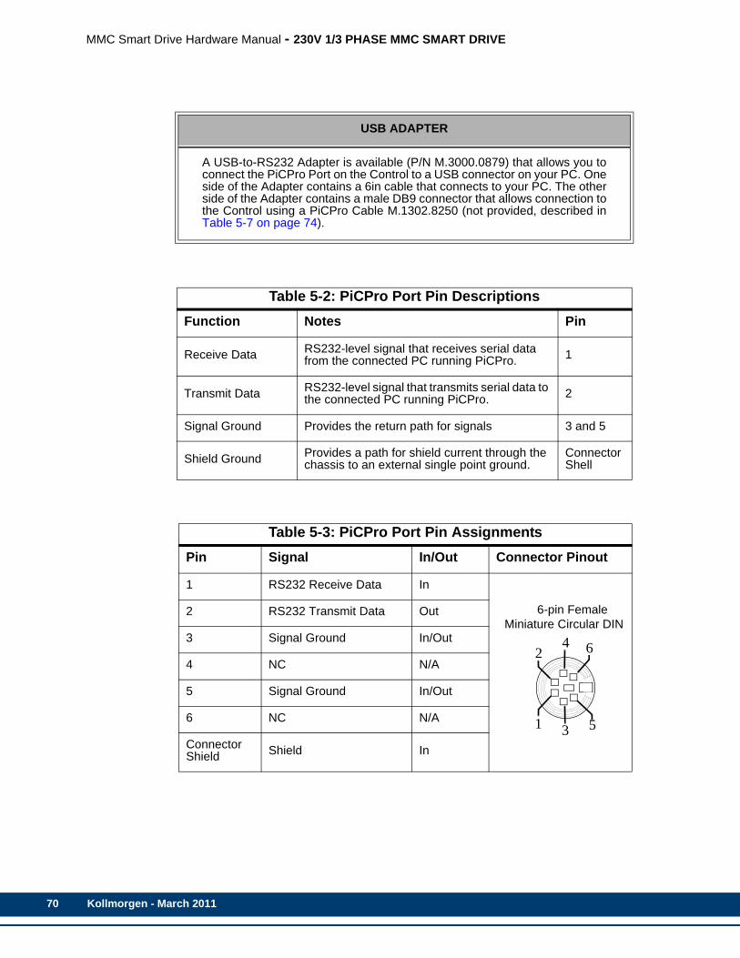
70
MMC Smart Drive Hardware Manual - 230V 1/3 PHASE MMC SMART DRIVE
USB ADAPTER
A USB-to-RS232 Adapter is available (P/N M.3000.0879) that allows you toconnect the PiCPro Port on the Control to a USB connector on your PC. Oneside of the Adapter contains a 6in cable that connects to your PC. The otherside of the Adapter contains a male DB9 connector that allows connection tothe Control using a PiCPro Cable M.1302.8250 (not provided, described inTable 5-7 on page 74).
Table 5-2: PiCPro Port Pin DescriptionsFunction Notes Pin
Receive Data RS232-level signal that receives serial data from the connected PC running PiCPro. 1
Transmit Data RS232-level signal that transmits serial data to the connected PC running PiCPro. 2
Signal Ground Provides the return path for signals 3 and 5
Shield Ground Provides a path for shield current through the chassis to an external single point ground.
ConnectorShell
Table 5-3: PiCPro Port Pin AssignmentsPin Signal In/Out Connector Pinout
1 RS232 Receive Data In
6-pin Female Miniature Circular DIN
2 RS232 Transmit Data Out
3 Signal Ground In/Out
4 NC N/A
5 Signal Ground In/Out
6 NC N/A
ConnectorShield Shield In
1
6
5
2
3
4
Kollmorgen - March 2011
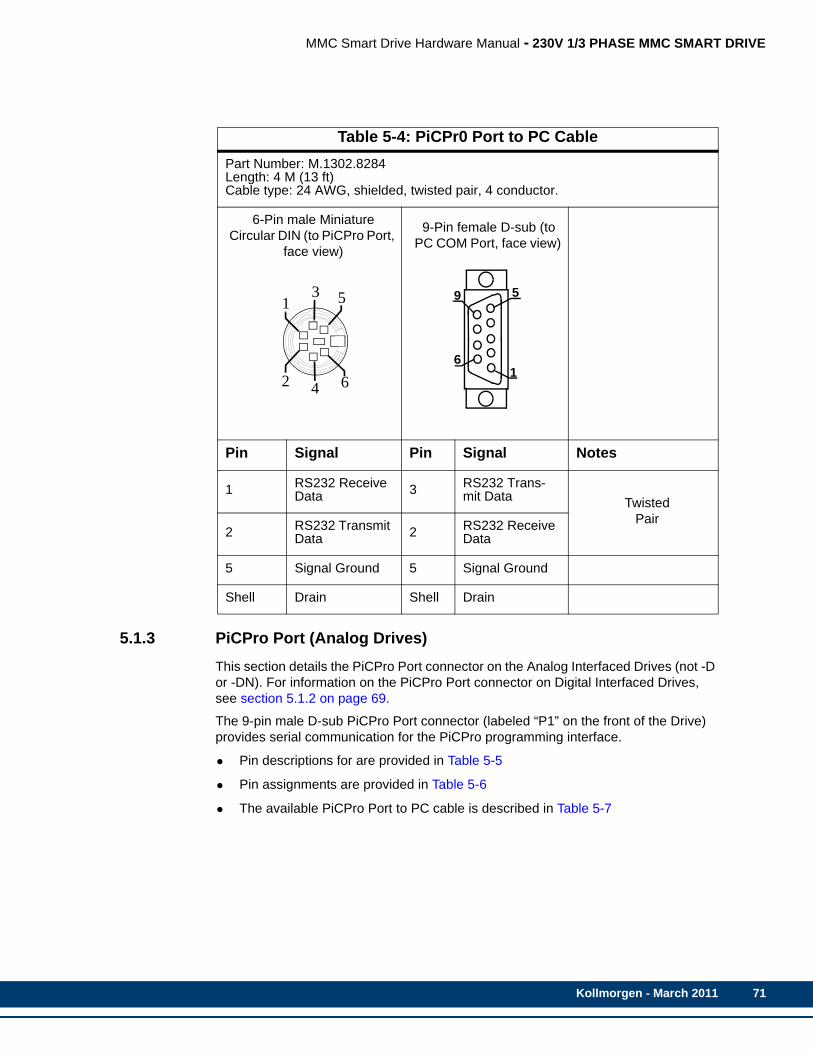
MMC Smart Drive Hardware Manual - 230V 1/3 PHASE MMC SMART DRIVE
5.1.3 PiCPro Port (Analog Drives)This section details the PiCPro Port connector on the Analog Interfaced Drives (not -D or -DN). For information on the PiCPro Port connector on Digital Interfaced Drives, see section 5.1.2 on page 69.
The 9-pin male D-sub PiCPro Port connector (labeled “P1” on the front of the Drive) provides serial communication for the PiCPro programming interface.
• Pin descriptions for are provided in Table 5-5
• Pin assignments are provided in Table 5-6
• The available PiCPro Port to PC cable is described in Table 5-7
Table 5-4: PiCPr0 Port to PC CablePart Number: M.1302.8284Length: 4 M (13 ft)Cable type: 24 AWG, shielded, twisted pair, 4 conductor.
6-Pin male Miniature Circular DIN (to PiCPro Port,
face view)
9-Pin female D-sub (to PC COM Port, face view)
Pin Signal Pin Signal Notes
1 RS232 Receive Data 3 RS232 Trans-
mit Data TwistedPair
2 RS232 Transmit Data 2 RS232 Receive
Data
5 Signal Ground 5 Signal Ground
Shell Drain Shell Drain
2
5
6
1
4
3
6
59
1
Kollmorgen - March 2011 71
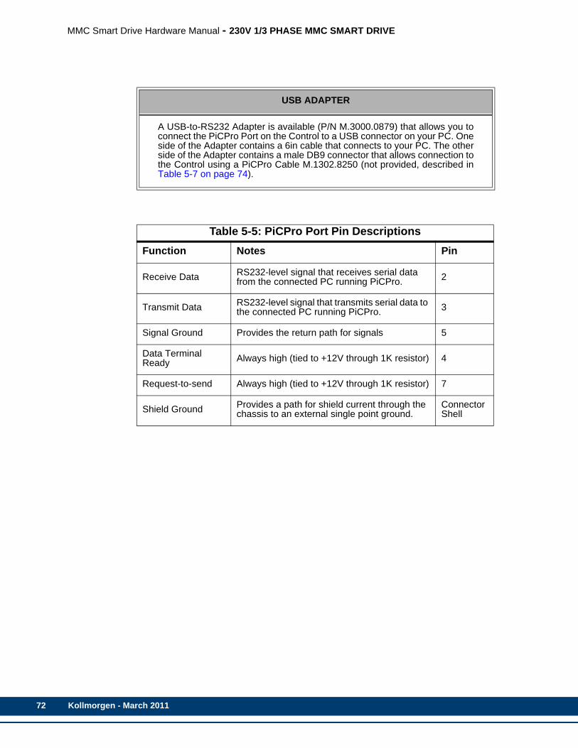
72
MMC Smart Drive Hardware Manual - 230V 1/3 PHASE MMC SMART DRIVE
USB ADAPTER
A USB-to-RS232 Adapter is available (P/N M.3000.0879) that allows you toconnect the PiCPro Port on the Control to a USB connector on your PC. Oneside of the Adapter contains a 6in cable that connects to your PC. The otherside of the Adapter contains a male DB9 connector that allows connection tothe Control using a PiCPro Cable M.1302.8250 (not provided, described inTable 5-7 on page 74).
Table 5-5: PiCPro Port Pin DescriptionsFunction Notes Pin
Receive Data RS232-level signal that receives serial data from the connected PC running PiCPro. 2
Transmit Data RS232-level signal that transmits serial data to the connected PC running PiCPro. 3
Signal Ground Provides the return path for signals 5
Data Terminal Ready Always high (tied to +12V through 1K resistor) 4
Request-to-send Always high (tied to +12V through 1K resistor) 7
Shield Ground Provides a path for shield current through the chassis to an external single point ground.
Connector Shell
Kollmorgen - March 2011
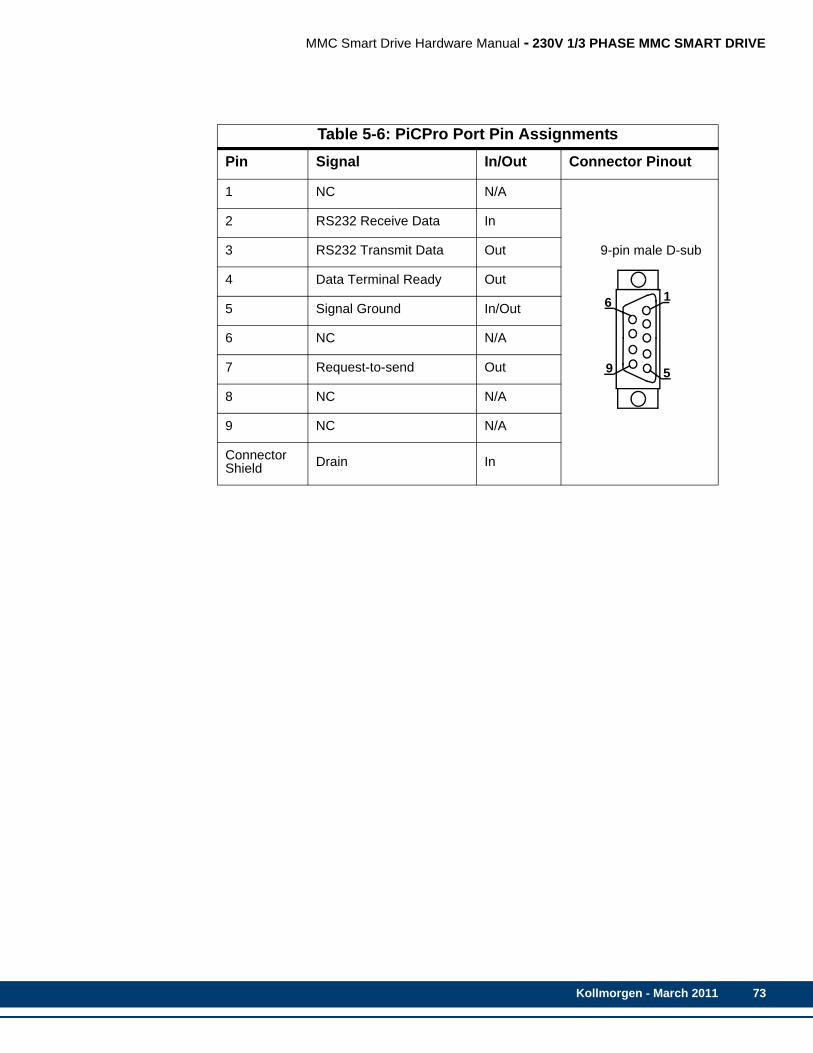
MMC Smart Drive Hardware Manual - 230V 1/3 PHASE MMC SMART DRIVE
Table 5-6: PiCPro Port Pin AssignmentsPin Signal In/Out Connector Pinout
1 NC N/A
9-pin male D-sub
2 RS232 Receive Data In
3 RS232 Transmit Data Out
4 Data Terminal Ready Out
5 Signal Ground In/Out
6 NC N/A
7 Request-to-send Out
8 NC N/A
9 NC N/A
Connector Shield Drain In
1
9 5
6
Kollmorgen - March 2011 73
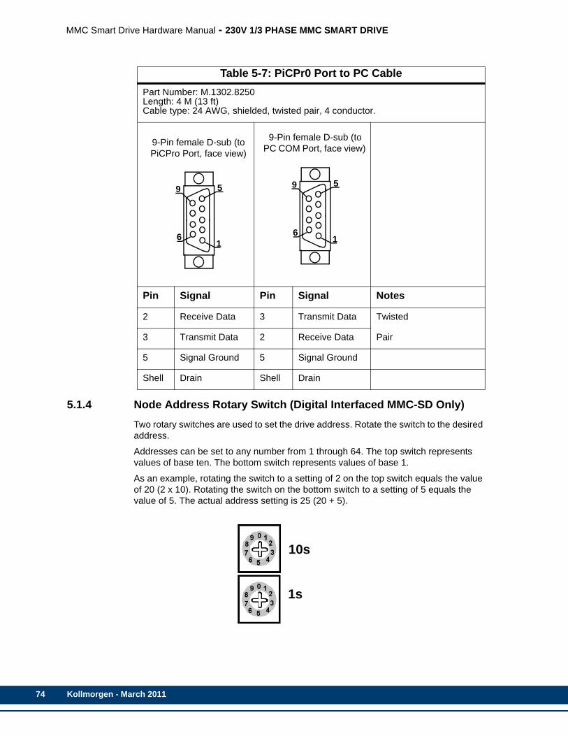
74
MMC Smart Drive Hardware Manual - 230V 1/3 PHASE MMC SMART DRIVE
5.1.4 Node Address Rotary Switch (Digital Interfaced MMC-SD Only)Two rotary switches are used to set the drive address. Rotate the switch to the desired address.
Addresses can be set to any number from 1 through 64. The top switch represents values of base ten. The bottom switch represents values of base 1.
As an example, rotating the switch to a setting of 2 on the top switch equals the value of 20 (2 x 10). Rotating the switch on the bottom switch to a setting of 5 equals the value of 5. The actual address setting is 25 (20 + 5).
Table 5-7: PiCPr0 Port to PC CablePart Number: M.1302.8250Length: 4 M (13 ft)Cable type: 24 AWG, shielded, twisted pair, 4 conductor.
9-Pin female D-sub (to PiCPro Port, face view)
9-Pin female D-sub (to PC COM Port, face view)
Pin Signal Pin Signal Notes
2 Receive Data 3 Transmit Data Twisted
3 Transmit Data 2 Receive Data Pair
5 Signal Ground 5 Signal Ground
Shell Drain Shell Drain
6
59
16
59
1
10s
1s
Kollmorgen - March 2011
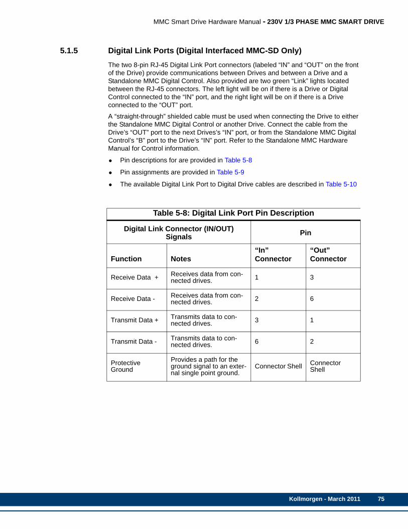
MMC Smart Drive Hardware Manual - 230V 1/3 PHASE MMC SMART DRIVE
5.1.5 Digital Link Ports (Digital Interfaced MMC-SD Only)The two 8-pin RJ-45 Digital Link Port connectors (labeled “IN” and “OUT” on the front of the Drive) provide communications between Drives and between a Drive and a Standalone MMC Digital Control. Also provided are two green “Link” lights located between the RJ-45 connectors. The left light will be on if there is a Drive or Digital Control connected to the “IN” port, and the right light will be on if there is a Drive connected to the “OUT” port.
A “straight-through” shielded cable must be used when connecting the Drive to either the Standalone MMC Digital Control or another Drive. Connect the cable from the Drive’s “OUT” port to the next Drives’s “IN” port, or from the Standalone MMC Digital Control’s “B” port to the Drive’s “IN” port. Refer to the Standalone MMC Hardware Manual for Control information.
• Pin descriptions for are provided in Table 5-8
• Pin assignments are provided in Table 5-9
• The available Digital Link Port to Digital Drive cables are described in Table 5-10
Table 5-8: Digital Link Port Pin Description
Digital Link Connector (IN/OUT) Signals Pin
Function Notes“In”Connector
“Out” Connector
Receive Data + Receives data from con-nected drives. 1 3
Receive Data - Receives data from con-nected drives. 2 6
Transmit Data + Transmits data to con-nected drives. 3 1
Transmit Data - Transmits data to con-nected drives. 6 2
Protective Ground
Provides a path for the ground signal to an exter-nal single point ground.
Connector Shell Connector Shell
Kollmorgen - March 2011 75

76
MMC Smart Drive Hardware Manual - 230V 1/3 PHASE MMC SMART DRIVE
Table 5-9: Digital Link Port Pin AssignmentsPin Label In/Out Connector Pinout
IN Connector
1 Receive + In
RJ-45 Connectors
2 Receive - In
3 Transmit + Out
4 Not Used N/A
5 Not Used N/A
6 Transmit - Out
7 Not Used N/A
8 Not Used N/A
Connector Shield
Provides a path for the ground signal to an ex-ternal single point ground.
In
OUT Connector
1 Transmit + Out
2 Transmit - Out
3 Receive + In
4 Not Used N/A
5 Not Used N/A
6 Receive - In
7 Not Used N/A
8 Not Used N/A
Connector Shield
Provides a path for the ground signal to an ex-ternal single point ground.
In
1
8
1
8
“IN”LINK
“OUT”LINKLEDLED
Kollmorgen - March 2011
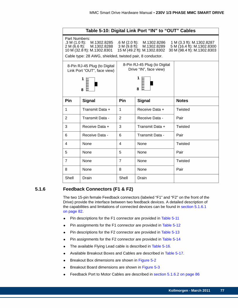
MMC Smart Drive Hardware Manual - 230V 1/3 PHASE MMC SMART DRIVE
03
5.1.6 Feedback Connectors (F1 & F2)The two 15-pin female Feedback connectors (labeled “F1” and “F2” on the front of the Drive) provide the interface between two feedback devices. A detailed description of the capabilities and limitations of connected devices can be found in section 5.1.6.1 on page 82.
• Pin descriptions for the F1 connector are provided in Table 5-11
• Pin assignments for the F1 connector are provided in Table 5-12
• Pin descriptions for the F2 connector are provided in Table 5-13
• Pin assignments for the F2 connector are provided in Table 5-14
• The available Flying Lead cable is described in Table 5-16.
• Available Breakout Boxes and Cables are described in Table 5-17.
• Breakout Box dimensions are shown in Figure 5-2
• Breakout Board dimensions are shown in Figure 5-3
• Feedback Port to Motor Cables are described in section 5.1.6.2 on page 86
Table 5-10: Digital Link Port “IN” to “OUT” CablesPart Numbers:.3 M (1.0 ft): M.1302.8285 .6 M (2.0 ft): M.1302.8286 1 M (3.3 ft): M.1302.82872 M (6.6 ft): M.1302.8288 3 M (9.8 ft): M.1302.8289 5 M (16.4 ft): M.1302.83010 M (32.8 ft): M.1302.8301 15 M (49.2 ft): M.1302.8302 30 M (98.4 ft): M.1302.830Cable type: 28 AWG, shielded, twisted pair, 8 conductor.
8-Pin RJ-45 Plug (to Digital Link Port “OUT”, face view)
8-Pin RJ-45 Plug (to Digital Drive “IN”, face view)
Pin Signal Pin Signal Notes
1 Transmit Data + 1 Receive Data + Twisted
2 Transmit Data - 2 Receive Data - Pair
3 Receive Data + 3 Transmit Data + Twisted
6 Receive Data - 6 Transmit Data - Pair
4 None 4 None Twisted
5 None 5 None Pair
7 None 7 None Twisted
8 None 8 None Pair
Shell Drain Shell Drain
1
8
1
8
Kollmorgen - March 2011 77

78
MMC Smart Drive Hardware Manual - 230V 1/3 PHASE MMC SMART DRIVE
S
Ip
S
SC
MS
Sm
R
R
T
+p
+p
Se
Sm
Table 5-11: Pin Description for Feedback Connector (F1)
F1 Feedback Signals
ignal Type Signal Name Notes Pin
ncremental Encoder In-uts A1, A1/, B1, B1/, I1, I1/ Differential A quad B encoder
signals. 1, 2, 3, 4, 5, 10
inewave Encoder Inputs Sin, Sin/, Cos, Cos/ Sinewave Encoder signals 1, 2, 3, 4
inewave Encoder Data hannel In/Out
RS-485 Data +, RS-485 Data -, RS-485 Clock+, RS-485 Clock-
RS-485 signals for connecting the Sinewave Encoder Data Channel to the drive
5, 10, 12, 13
otor Commutation Hall ensor Inputs
Commutation Track S1, S2, S3
Hall device input signals that are used to initialize the com-mutation angle. They consist of a 74HC14 input with 10μs filter and 1 K pull up to +5V. Shared with F2.
12, 13, 8
inewave Encoder Com-utation Inputs
Commutation Sin+,Commutation Sin-
Sinewave signals that are used to initialize the motor commuta-tion angle when a Heidenhein Sincoder is used as the motor feedback device.
12, 13
esolver Inputs Sin+, Sin-, Cos+, Cos-Resolver rotor feedback signals used when optional Resolver In-terface Board is installed.
1, 2, 3, 4
esolver Outputs Carrier+, Carrier-Resolver rotor excitation signals used when optional Resolver In-terface Board is installed.
5, 10
emperature Input Temperature
Thermostat (normally- closed) or Thermistor (Phillips KTY84-130 PTC or equivalent recom-mended) input for detecting over temperature conditions within the motor.
11
5V Encoder Power Out-uts +5V Source
Regulated +5VDC for powering the attached encoder (F1 pin 14 + F2 pin 14 = 500ma max).
14
9V Encoder Power Out-uts +9V Source
Regulated +9VDC for powering the attached encoder (F1 pin 7 + F2 pin 7 = 150ma max).
7
inewave Encoder Refer-nce Mark Input Ref Mark, Ref Mark/
Reference Mark input used with some Sinewave Encoders used to indicate motor position within one revolution.
5, 10
ignal and Power Com-on Common
Return path for feedback sig-nals and power supplies (+5V and +9V).
6
Kollmorgen - March 2011
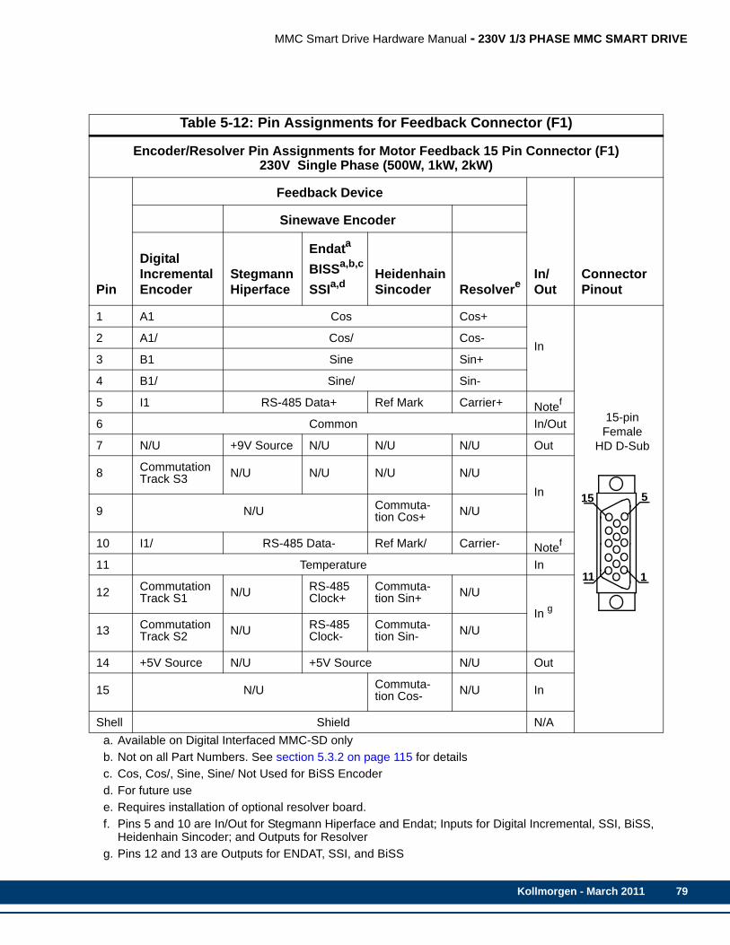
MMC Smart Drive Hardware Manual - 230V 1/3 PHASE MMC SMART DRIVE
P
1
2
3
4
5
6
7
8
9
1
1
1
1
1
1
S
Table 5-12: Pin Assignments for Feedback Connector (F1)
Encoder/Resolver Pin Assignments for Motor Feedback 15 Pin Connector (F1)230V Single Phase (500W, 1kW, 2kW)
in
Feedback Device
In/Out
Connector Pinout
Sinewave Encoder
Digital Incremental Encoder
Stegmann Hiperface
Endata
BISSa,b,c
SSIa,d
a. Available on Digital Interfaced MMC-SD onlyb. Not on all Part Numbers. See section 5.3.2 on page 115 for detailsc. Cos, Cos/, Sine, Sine/ Not Used for BiSS Encoderd. For future use
Heidenhain Sincoder Resolvere
e. Requires installation of optional resolver board.
A1 Cos Cos+
In
15-pin Female
HD D-Sub
A1/ Cos/ Cos-
B1 Sine Sin+
B1/ Sine/ Sin-
I1 RS-485 Data+ Ref Mark Carrier+ Notef
f. Pins 5 and 10 are In/Out for Stegmann Hiperface and Endat; Inputs for Digital Incremental, SSI, BiSS, Heidenhain Sincoder; and Outputs for Resolver
Common In/Out
N/U +9V Source N/U N/U N/U Out
CommutationTrack S3 N/U N/U N/U N/U
InN/U Commuta-
tion Cos+ N/U
0 I1/ RS-485 Data- Ref Mark/ Carrier- Notef
1 Temperature In
2 CommutationTrack S1 N/U RS-485
Clock+Commuta-tion Sin+ N/U
In g
g. Pins 12 and 13 are Outputs for ENDAT, SSI, and BiSS
3 CommutationTrack S2 N/U RS-485
Clock-Commuta-tion Sin- N/U
4 +5V Source N/U +5V Source N/U Out
5 N/U Commuta-tion Cos- N/U In
hell Shield N/A
5
1
15
11
Kollmorgen - March 2011 79
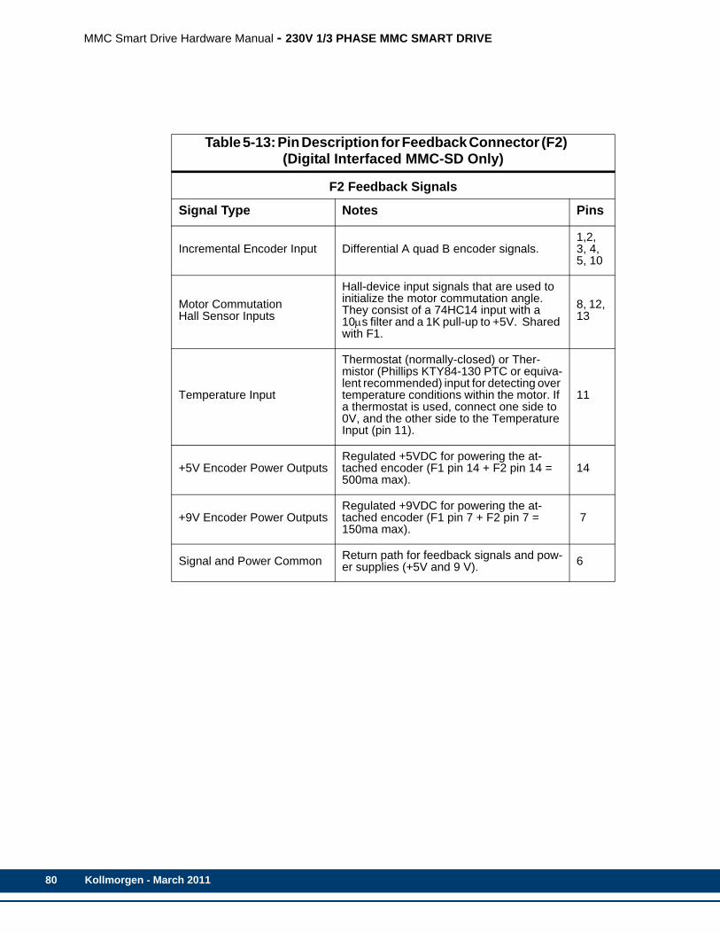
80
MMC Smart Drive Hardware Manual - 230V 1/3 PHASE MMC SMART DRIVE
Table 5-13: Pin Description for Feedback Connector (F2) (Digital Interfaced MMC-SD Only)
F2 Feedback Signals
Signal Type Notes Pins
Incremental Encoder Input Differential A quad B encoder signals.1,2, 3, 4, 5, 10
Motor CommutationHall Sensor Inputs
Hall-device input signals that are used to initialize the motor commutation angle. They consist of a 74HC14 input with a 10μs filter and a 1K pull-up to +5V. Shared with F1.
8, 12, 13
Temperature Input
Thermostat (normally-closed) or Ther-mistor (Phillips KTY84-130 PTC or equiva-lent recommended) input for detecting over temperature conditions within the motor. If a thermostat is used, connect one side to 0V, and the other side to the Temperature Input (pin 11).
11
+5V Encoder Power OutputsRegulated +5VDC for powering the at-tached encoder (F1 pin 14 + F2 pin 14 = 500ma max).
14
+9V Encoder Power OutputsRegulated +9VDC for powering the at-tached encoder (F1 pin 7 + F2 pin 7 = 150ma max).
7
Signal and Power Common Return path for feedback signals and pow-er supplies (+5V and 9 V). 6
Kollmorgen - March 2011
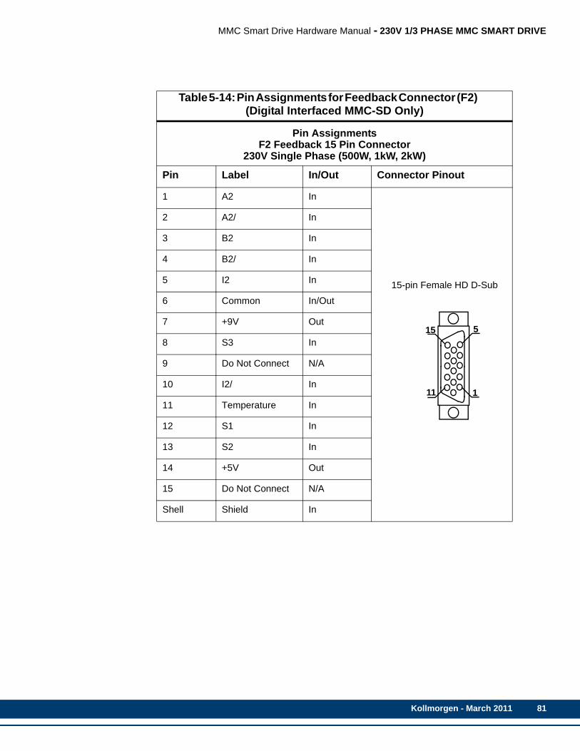
MMC Smart Drive Hardware Manual - 230V 1/3 PHASE MMC SMART DRIVE
Table 5-14: Pin Assignments for Feedback Connector (F2) (Digital Interfaced MMC-SD Only)
Pin AssignmentsF2 Feedback 15 Pin Connector
230V Single Phase (500W, 1kW, 2kW)
Pin Label In/Out Connector Pinout
1 A2 In
15-pin Female HD D-Sub
2 A2/ In
3 B2 In
4 B2/ In
5 I2 In
6 Common In/Out
7 +9V Out
8 S3 In
9 Do Not Connect N/A
10 I2/ In
11 Temperature In
12 S1 In
13 S2 In
14 +5V Out
15 Do Not Connect N/A
Shell Shield In
5
1
15
11
Kollmorgen - March 2011 81

82
MMC Smart Drive Hardware Manual - 230V 1/3 PHASE MMC SMART DRIVE
5.1.6.1 Feedback Connectors (F1 and F2) DetailsThe F1 and F2 Feedback connectors support a variety of devices and functions. This section helps clarify the capabilities and limitations of connected devices.
• All signals (other than the encoder inputs) are bussed internally between the two feedback connectors F1 and F2. The bussed signals include motor commutation inputs, temperature input, +5V power, +9V power, and encoder power outputs.
• F1 can interface with incremental encoders, sinewave encoders, and resolvers (using the optional resolver interface module). These signals are conditioned and routed to the Drive I/O connector.
• F2 can be designated (in PiCPro) as the motor feedback connector but only if F1 is not (either one or the other must be designated as such).
• F2 can interface with only incremental type encoders.
• The hall sensor inputs on F1 and F2 are connected together, allowing either F1 or F2 to accept the hall sensor signal, but NOT both. Only one feedback may be con-nected to motor hall sensor inputs.
• Refer to Table 5-15 for more information regarding the valid combinations of feed-back on the F1 and F2 connectors.
Table 5-15: Supported Feedback Combinations
Drive Feedback Configuration 1 and 4 (in PiCPro Drive Setup)
F1 (Motor mounted feedback device for motor control)
F2 (Externally mounted feedback device for position
feedback)
•Incremental Encoder with commutation halls
•Resolver•Sincoder with commutation halls•Endat2.1 (single or multi-turn)•Stegmann Hiperface (single or multi-
turn)•BiSS (single or multi-turn)
•Incremental Encoder without commutation halls
Drive Feedback Configuration 2 and 3 (in PiCPro Drive Setup)
F1 (Externally mounted feedback device for position
feedback)F2 (Motor mounted feedback
device for motor control)
•Sincoder without commutation halls•Resolver
•Incremental Encoder with commutation halls
Kollmorgen - March 2011
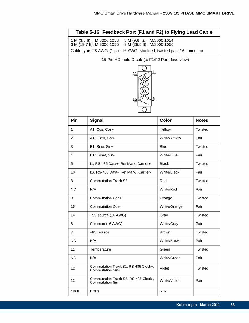
MMC Smart Drive Hardware Manual - 230V 1/3 PHASE MMC SMART DRIVE
Table 5-16: Feedback Port (F1 and F2) to Flying Lead Cable1 M (3.3 ft): M.3000.1053 3 M (9.8 ft): M.3000.10546 M (19.7 ft): M.3000.1055 9 M (29.5 ft): M.3000.1056Cable type: 28 AWG, (1 pair 16 AWG) shielded, twisted pair, 16 conductor.
15-Pin HD male D-sub (to F1/F2 Port, face view)
Pin Signal Color Notes
1 A1, Cos, Cos+ Yellow Twisted
2 A1/, Cos/, Cos- White/Yellow Pair
3 B1, Sine, Sin+ Blue Twisted
4 B1/, Sine/, Sin- White/Blue Pair
5 I1, RS-485 Data+, Ref Mark, Carrier+ Black Twisted
10 I1/, RS-485 Data-, Ref Mark/, Carrier- White/Black Pair
8 Commutation Track S3 Red Twisted
NC N/A White/Red Pair
9 Commutation Cos+ Orange Twisted
15 Commutation Cos- White/Orange Pair
14 +5V source,(16 AWG) Gray Twisted
6 Common (16 AWG) White/Gray Pair
7 +9V Source Brown Twisted
NC N/A White/Brown Pair
11 Temperature Green Twisted
NC N/A White/Green Pair
12 Commutation Track S1, RS-485 Clock+, Commutation Sin+ Violet Twisted
13 Commutation Track S2, RS-485 Clock-, Commutation Sin- White/Violet Pair
Shell Drain N/A
5
1
15
11
Kollmorgen - March 2011 83

84
MMC Smart Drive Hardware Manual - 230V 1/3 PHASE MMC SMART DRIVE
Table 5-17: Feedback Ports (F1 and F2) Breakout Box and CablesDescription Length Part Number
MMC-SD F1/F2 Port Breakout Boarda
a. The Breakout Board (see Figure 5-3 on page 85) is mounted directly to the F1 and/or F2 connector, and provides screw terminals wire termination.
N/A M.1302.6970
MMC-SD F1/F2 Port Breakout Boxb
b. The Breakout Box (see Figure 5-2 on page 85) is DIN-rail mounted, and provides screw terminal wire termination. Use one of the cables listed in the table to con-nect between the F1 and/or F2 connector and the Breakout Box.
N/A M.1302.6972
MMC-SD F1/F2 Port to Breakout Box Cable
1 M (3.3 ft) M.1302.6976
3 M (9.8 ft) M.1302.6977
9 M (29.5 ft) M.1302.6979
15 M (49.2 ft) M.1302.6980
MMC-SD F1/F2 Port Breakout Box and Cable Kits. These kits include an M.1302.6972 Breakout Box and an inter-connect cable of the indicated length
1 M (3.3 ft) M.1302.7005
3 M (9.8 ft) M.1302.7006
9 M (29.5 ft) M.1302.7007
15 M (49.2 ft) M.1302.7008
Kollmorgen - March 2011

MMC Smart Drive Hardware Manual - 230V 1/3 PHASE MMC SMART DRIVE
Figure 5-2: Feedback Port (F1 and F2) Breakout Box Dimensions
Figure 5-3: Feedback Port (F1 and F2) Breakout Board Dimensions
Kollmorgen - March 2011 85
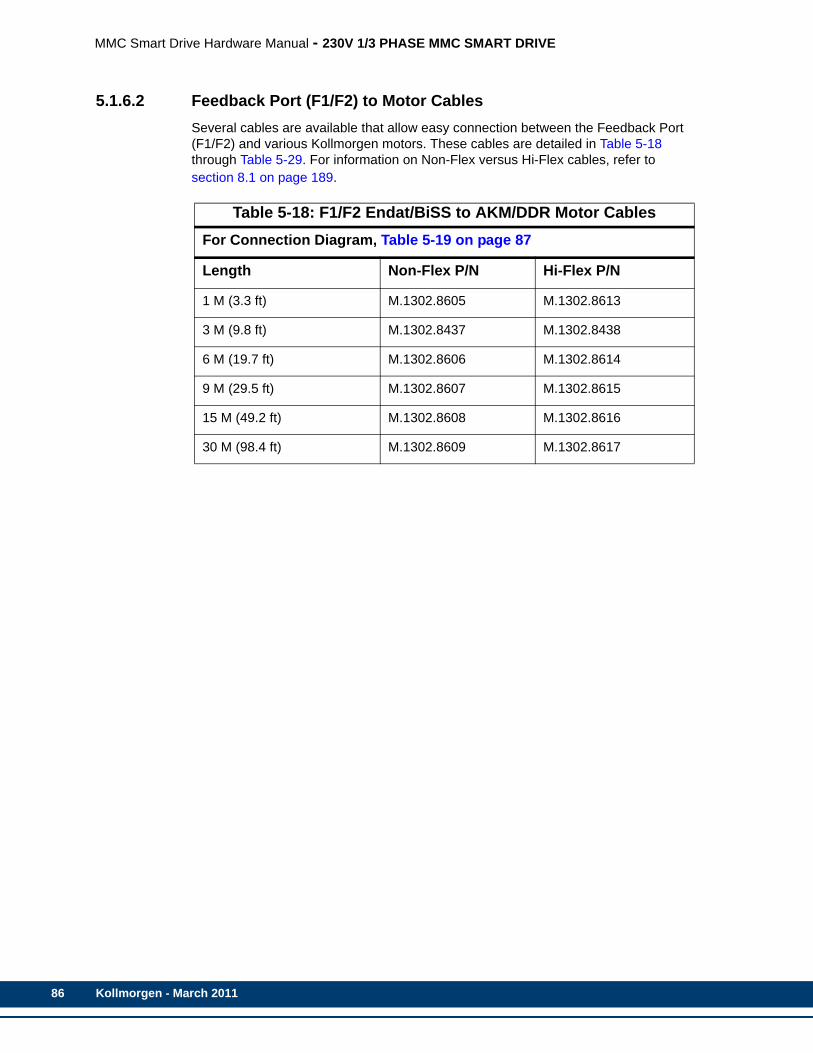
86
MMC Smart Drive Hardware Manual - 230V 1/3 PHASE MMC SMART DRIVE
5.1.6.2 Feedback Port (F1/F2) to Motor CablesSeveral cables are available that allow easy connection between the Feedback Port (F1/F2) and various Kollmorgen motors. These cables are detailed in Table 5-18 through Table 5-29. For information on Non-Flex versus Hi-Flex cables, refer to section 8.1 on page 189.
Table 5-18: F1/F2 Endat/BiSS to AKM/DDR Motor CablesFor Connection Diagram, Table 5-19 on page 87
Length Non-Flex P/N Hi-Flex P/N
1 M (3.3 ft) M.1302.8605 M.1302.8613
3 M (9.8 ft) M.1302.8437 M.1302.8438
6 M (19.7 ft) M.1302.8606 M.1302.8614
9 M (29.5 ft) M.1302.8607 M.1302.8615
15 M (49.2 ft) M.1302.8608 M.1302.8616
30 M (98.4 ft) M.1302.8609 M.1302.8617
Kollmorgen - March 2011
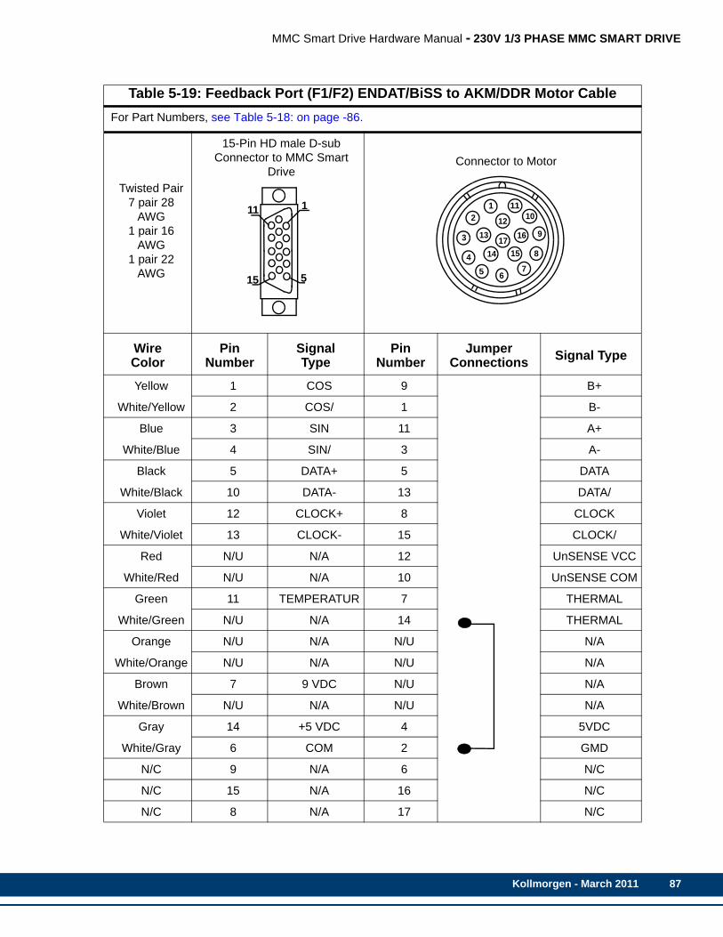
MMC Smart Drive Hardware Manual - 230V 1/3 PHASE MMC SMART DRIVE
Table 5-19: Feedback Port (F1/F2) ENDAT/BiSS to AKM/DDR Motor CableFor Part Numbers, see Table 5-18: on page -86.
Twisted Pair7 pair 28
AWG1 pair 16
AWG1 pair 22
AWG
15-Pin HD male D-sub Connector to MMC Smart
DriveConnector to Motor
Wire Color
Pin Number
Signal Type
Pin Number
Jumper Connections Signal Type
Yellow 1 COS 9 B+
White/Yellow 2 COS/ 1 B-
Blue 3 SIN 11 A+
White/Blue 4 SIN/ 3 A-
Black 5 DATA+ 5 DATA
White/Black 10 DATA- 13 DATA/
Violet 12 CLOCK+ 8 CLOCK
White/Violet 13 CLOCK- 15 CLOCK/
Red N/U N/A 12 UnSENSE VCC
White/Red N/U N/A 10 UnSENSE COM
Green 11 TEMPERATUR 7 THERMAL
White/Green N/U N/A 14 THERMAL
Orange N/U N/A N/U N/A
White/Orange N/U N/A N/U N/A
Brown 7 9 VDC N/U N/A
White/Brown N/U N/A N/U N/A
Gray 14 +5 VDC 4 5VDC
White/Gray 6 COM 2 GMD
N/C 9 N/A 6 N/C
N/C 15 N/A 16 N/C
N/C 8 N/A 17 N/C
5
1
15
11 12
3
45 6
7
8
9
1011
1213
14 15
1617
Kollmorgen - March 2011 87
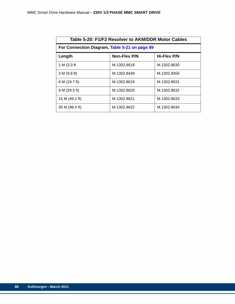
88
MMC Smart Drive Hardware Manual - 230V 1/3 PHASE MMC SMART DRIVE
Table 5-20: F1/F2 Resolver to AKM/DDR Motor CablesFor Connection Diagram, Table 5-21 on page 89
Length Non-Flex P/N Hi-Flex P/N
1 M (3.3 ft M.1302.8618 M.1302.8630
3 M (9.8 ft) M.1302.8439 M.1302.8450
6 M (19.7 ft) M.1302.8619 M.1302.8631
9 M (29.5 ft) M.1302.8620 M.1302.8632
15 M (49.2 ft) M.1302.8621 M.1302.8633
30 M (98.4 ft) M.1302.8622 M.1302.8634
Kollmorgen - March 2011

MMC Smart Drive Hardware Manual - 230V 1/3 PHASE MMC SMART DRIVE
Table 5-21: Feedback Port (F1/F2) Resolver AKM/DDR MotorFor Part Numbers, see Table 5-20: on page -88.
Twisted Pair
4 pair 24 AWG
D-sub 15-Pin HD Male Connector to MMC
Smart DriveConnector to Motor
Wire Color
Pin Number
Signal Type
Pin Number
Jumper Connections
Signal Type
Black 1 COS+ 7 COS+
White/Black 2 COS- 3 COS-
Red 3 SIN+ 8 SIN+
White/Red 4 SIN- 4 SIN-
Green 5 REF+ 9 REF+
White/Green 10 REF- 5 REF-
Orange 11 TEMP+ 2 TEMP+
White/Orange 6 COM 6 TEMP-
N/C 7 9 VDC 9 9 VDC
N/C 8 N/A N/U N/A
N/C 9 +5 VDC 10 +5 VDC
N/C 12 COM 1 N/C
N/C 13 N/A 10 N/C
N/C 14 N/A 11 N/C
N/C 15 N/A 12 N/C
5
1
15
11
Kollmorgen - March 2011 89

90
MMC Smart Drive Hardware Manual - 230V 1/3 PHASE MMC SMART DRIVE
Table 5-22: F1/F2 Encoder to AKM/DDR Motor CablesFor Connection Diagram, Table 5-23 on page 91
Length Non-Flex P/N Hi-Flex P/N
1 M (3.3 ft) M.1302.8590 M.1302.8600
3 M (9.8 ft) M.1302.8447 M.1302.8435
6 M (19.7 ft) M.1302.8591 M.1302.8601
9 M (29.5 ft) M.1302.8542 M.1302.8602
15 M (49.2 ft) M.1302.8594 M.1302.8603
30 M (98.4 ft) M.1302.8595 M.1302.8604
Kollmorgen - March 2011
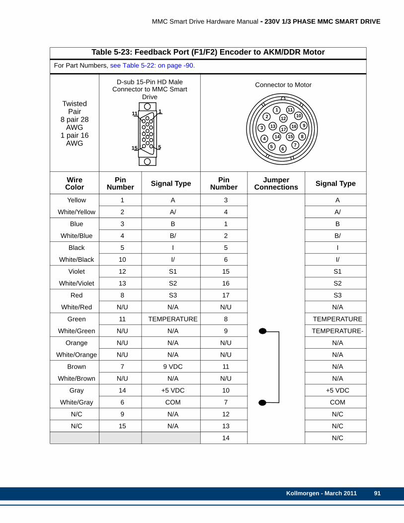
MMC Smart Drive Hardware Manual - 230V 1/3 PHASE MMC SMART DRIVE
Table 5-23: Feedback Port (F1/F2) Encoder to AKM/DDR MotorFor Part Numbers, see Table 5-22: on page -90.
Twisted Pair
8 pair 28 AWG
1 pair 16 AWG
D-sub 15-Pin HD Male Connector to MMC Smart
Drive
Connector to Motor
Wire Color
Pin Number Signal Type Pin
NumberJumper
Connections Signal Type
Yellow 1 A 3 A
White/Yellow 2 A/ 4 A/
Blue 3 B 1 B
White/Blue 4 B/ 2 B/
Black 5 I 5 I
White/Black 10 I/ 6 I/
Violet 12 S1 15 S1
White/Violet 13 S2 16 S2
Red 8 S3 17 S3
White/Red N/U N/A N/U N/A
Green 11 TEMPERATURE 8 TEMPERATURE
White/Green N/U N/A 9 TEMPERATURE-
Orange N/U N/A N/U N/A
White/Orange N/U N/A N/U N/A
Brown 7 9 VDC 11 N/A
White/Brown N/U N/A N/U N/A
Gray 14 +5 VDC 10 +5 VDC
White/Gray 6 COM 7 COM
N/C 9 N/A 12 N/C
N/C 15 N/A 13 N/C
14 N/C
5
1
15
111
2
3
45 6
7
8
9
1011
1213
14 15
1617
Kollmorgen - March 2011 91

92
MMC Smart Drive Hardware Manual - 230V 1/3 PHASE MMC SMART DRIVE
Table 5-24: F1/F2 Encoder to LSM/MSM Motor CablesFor Connection Diagram, Table 5-25 on page 93
Length Non-Flex P/N Hi-Flex P/N
1 M (3.3 ft) M.1302.0944 M.1302.5834
3 M (9.8 ft) M.1302.0945 M.1302.5835
9 M (29.5 ft) M.1302.0946 M.1302.5836
15 M (49.2 ft) M.1302.0947 M.1302.5837
30 M (98.4 ft) M.1302.0948 M.1302.5838
Kollmorgen - March 2011

MMC Smart Drive Hardware Manual - 230V 1/3 PHASE MMC SMART DRIVE
Table 5-25: Feedback Port (F1/F2) Encoder to LSM or MSM MotorsFor Part Numbers, see Table 5-24: on page -92.
Twisted Pair8 pair 28
AWG1 pair 16
AWG
D-sub 15-Pin HD Male Connector to MMC Smart Drive Connector to Motor
Wire Color
Pin Number Signal Type Pin
NumberJumper
Connections Signal Type
Yellow 1 A 1 A
White/Yellow 2 A/ 2 A/
Blue 3 B 3 B
White/Blue 4 B/ 4 B/
Black 5 I 5 I
White/Black 10 I/ 6 I/
Violet 12 S1 15 S1
White/Violet 13 S2 16 S2
Red 8 S3 17 S3
White/Red N/U N/A N/U N/A
Green 11 TEMPERATURE 13 TEMPERATURE
White/Green N/U N/A 14 TEMPERATURE-
Orange N/U N/A N/U N/A
White/Orange N/U N/A N/U N/A
Brown 7 9 VDC 9 9 VDC
White/Brown N/U N/A N/U N/A
Gray 14 +5 VDC 10 +5 VDC
White/Gray 6 COM 11 COM
N/C 9 N/A 7 N/C
N/C 15 N/A 8 N/C
12 N/C
5
1
15
111
2
3
45 6
7
8
9
1011
1213
14 15
1617
Kollmorgen - March 2011 93
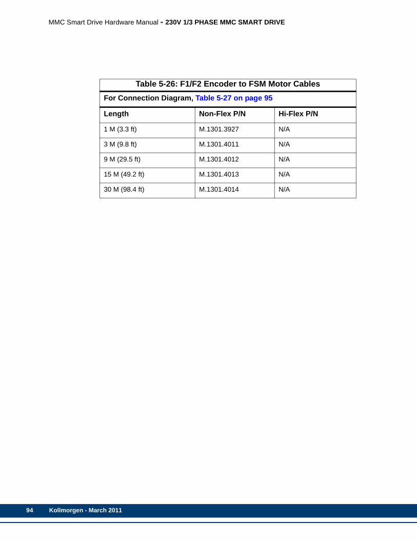
94
MMC Smart Drive Hardware Manual - 230V 1/3 PHASE MMC SMART DRIVE
Table 5-26: F1/F2 Encoder to FSM Motor CablesFor Connection Diagram, Table 5-27 on page 95
Length Non-Flex P/N Hi-Flex P/N
1 M (3.3 ft) M.1301.3927 N/A
3 M (9.8 ft) M.1301.4011 N/A
9 M (29.5 ft) M.1301.4012 N/A
15 M (49.2 ft) M.1301.4013 N/A
30 M (98.4 ft) M.1301.4014 N/A
Kollmorgen - March 2011
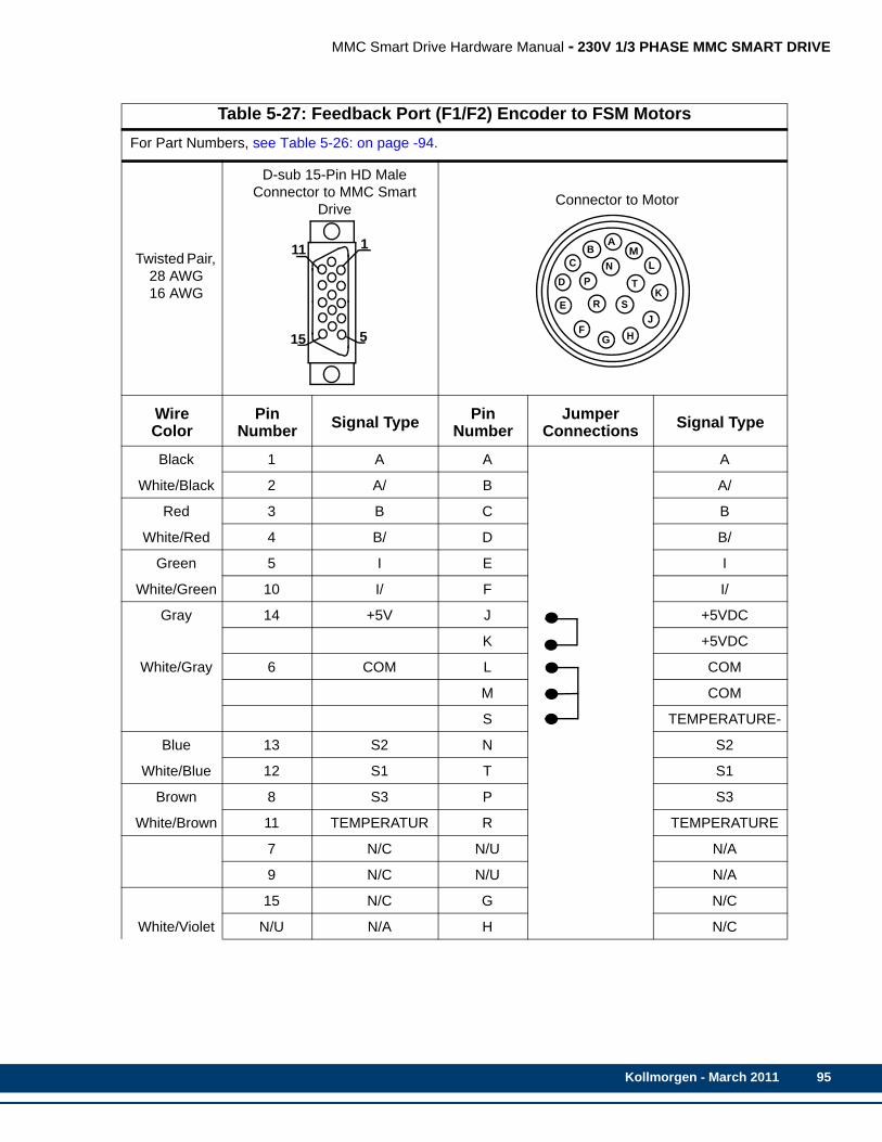
MMC Smart Drive Hardware Manual - 230V 1/3 PHASE MMC SMART DRIVE
Table 5-27: Feedback Port (F1/F2) Encoder to FSM MotorsFor Part Numbers, see Table 5-26: on page -94.
Twisted Pair, 28 AWG16 AWG
D-sub 15-Pin HD Male Connector to MMC Smart
Drive Connector to Motor
Wire Color
Pin Number Signal Type Pin
NumberJumper
Connections Signal Type
Black 1 A A A
White/Black 2 A/ B A/
Red 3 B C B
White/Red 4 B/ D B/
Green 5 I E I
White/Green 10 I/ F I/
Gray 14 +5V J +5VDC
K +5VDC
White/Gray 6 COM L COM
M COM
S TEMPERATURE-
Blue 13 S2 N S2
White/Blue 12 S1 T S1
Brown 8 S3 P S3
White/Brown 11 TEMPERATUR R TEMPERATURE
7 N/C N/U N/A
9 N/C N/U N/A
15 N/C G N/C
White/Violet N/U N/A H N/C
5
1
15
11L
K
JHG
F
E
D
CB
A
NT
SR
P
M
Kollmorgen - March 2011 95
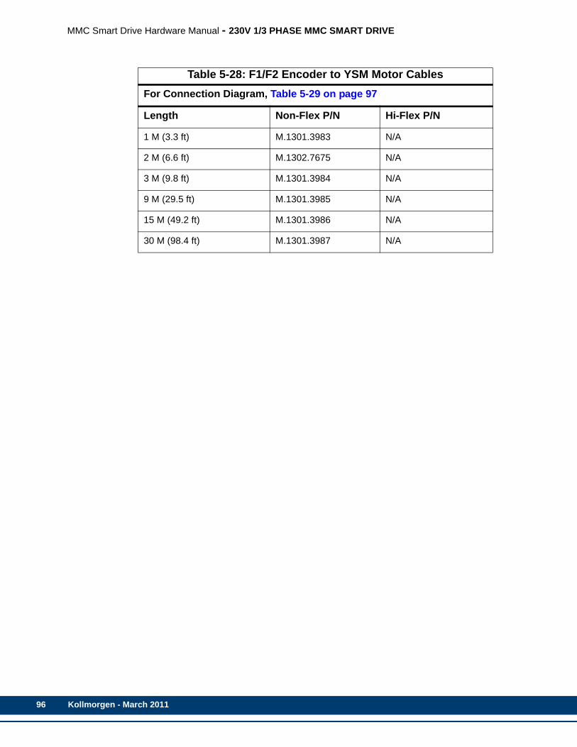
96
MMC Smart Drive Hardware Manual - 230V 1/3 PHASE MMC SMART DRIVE
Table 5-28: F1/F2 Encoder to YSM Motor CablesFor Connection Diagram, Table 5-29 on page 97
Length Non-Flex P/N Hi-Flex P/N
1 M (3.3 ft) M.1301.3983 N/A
2 M (6.6 ft) M.1302.7675 N/A
3 M (9.8 ft) M.1301.3984 N/A
9 M (29.5 ft) M.1301.3985 N/A
15 M (49.2 ft) M.1301.3986 N/A
30 M (98.4 ft) M.1301.3987 N/A
Kollmorgen - March 2011

MMC Smart Drive Hardware Manual - 230V 1/3 PHASE MMC SMART DRIVE
Table 5-29: Feedback Port (F1/F2) Encoder to YSM MotorsFor Part Numbers, see Table 5-28: on page -96.
Twisted Pair, 28 AWG 16 AWG
D-sub 15-Pin HD Male Connector to MMC Smart
Drive Connector to Motor
Wire Color
Pin Number
Signal Type
Pin Number
Jumper Connections
Signal Type
Black 1 A 9 A
White/Black 2 A/ 10
NO JUMPERED PINS
A/
Red 3 B 11 B
White/Red 4 B/ 12 B/
Green 5 I 13 I
White/Green 10 I/ 14 I/
Gray 14 +5V 22 +5VDC
White/Gray 6 COM 23 COM
Blue 13 S2 17 S2
White/Blue 12 S1 15 S1
Brown 8 S3 19 S3
White/Brown N/A N/C 24 N/C
N/A 7 N/C 1 N/C
N/A 9 N/C 2 N/C
N/A 15 N/C 3 N/C
N/A 11 N/C 4-8 N/C
16 N/C
18 N/C
20 N/C
21 N/C
25-28 N/C
5
1
15
114
9
15
212628
25
20
38
14
1
Kollmorgen - March 2011 97

98
MMC Smart Drive Hardware Manual - 230V 1/3 PHASE MMC SMART DRIVE
5.1.7 Drive I/O Connector (IO)The 26-pin HD female D-sub Drive I/O Port connector (labeled “IO” on the front of the Drive) provides connection between various devices and the Drive. This port provides one Analog Command Input, two differential Fast Inputs, several General Purpose I/O points (wiring example shown in See Figure 5-6 on page 104), and buffered versions of the feedback device connected to the F1 port.
• Pin descriptions are provided in Table 5-30
• Pin assignments are provided in Table 5-31
• Available MMC Control cables are described in Table 5-32
• The available Flying Lead cable is described in Table 5-33.
• Available Breakout Boxes and Cables are described in Table 5-34.
• Breakout Box dimensions are shown in Figure 5-4
• Breakout Board dimensions are shown in Figure 5-5
Table 5-30: Pin Description for Drive I/O Connector (IO)Signal Type Notes Pins
Analog Command Inputs (Analog In-terfaced MMC-SD only)
Analog velocity or torque commands of 0 to +/- 10V. Separate scale and offset parameters are used relative to the command signal being velocity or torque
14, 15
Fast Inputs (Digital Interfaced MMC-SD only)
Used for latching encoder position. 8, 9, 11, 12
General Purpose Software Assign-able Inputs
24VDC sourcing type. Default assignments: Pin 17 (GPIN1) = Drive Enable, Pin 18 (GPIN2) = Fault Reset
17, 18, 19, 20,21, 22
Buffered F1 Encod-er Output
RS485 drivers are used and the signal that is out-put depends on the encoder or resolver type used. See specifications in Chapter 5 of this manual. These signals are generated after the feedback from the F1connector is filtered and processed.
1, 2, 3, 4, 5, 6
General Purpose Software Assign-able Outputs
24VDC sourcing type. Default assignment:Pin 26 (GPOUT4) = Drive Ready
23, 24, 25, 26
IO24V, IO24COM 24 VDC inputs for powering GPIN and GPOUT I/O. 10, 16
Kollmorgen - March 2011
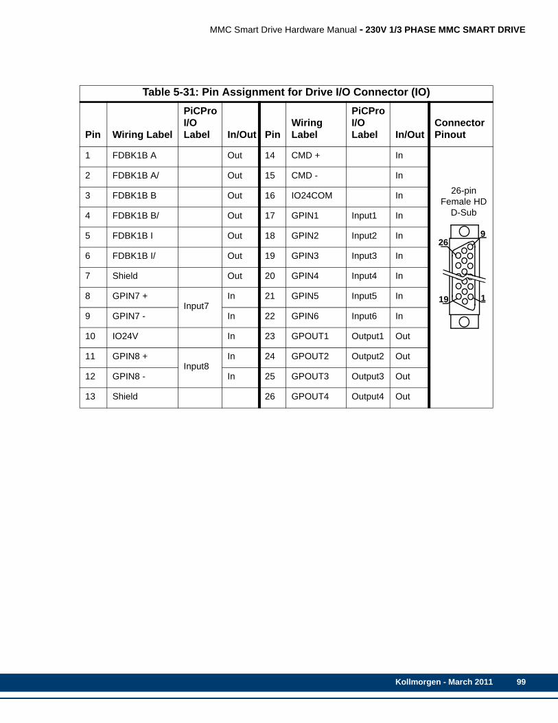
MMC Smart Drive Hardware Manual - 230V 1/3 PHASE MMC SMART DRIVE
Table 5-31: Pin Assignment for Drive I/O Connector (IO)
Pin Wiring Label
PiCPro I/O Label In/Out Pin
Wiring Label
PiCPro I/O Label In/Out
Connector Pinout
1 FDBK1B A Out 14 CMD + In
26-pin Female HD
D-Sub
2 FDBK1B A/ Out 15 CMD - In
3 FDBK1B B Out 16 IO24COM In
4 FDBK1B B/ Out 17 GPIN1 Input1 In
5 FDBK1B I Out 18 GPIN2 Input2 In
6 FDBK1B I/ Out 19 GPIN3 Input3 In
7 Shield Out 20 GPIN4 Input4 In
8 GPIN7 +Input7
In 21 GPIN5 Input5 In
9 GPIN7 - In 22 GPIN6 Input6 In
10 IO24V In 23 GPOUT1 Output1 Out
11 GPIN8 +Input8
In 24 GPOUT2 Output2 Out
12 GPIN8 - In 25 GPOUT3 Output3 Out
13 Shield 26 GPOUT4 Output4 Out
1
9
19
26
Kollmorgen - March 2011 99

100
MMC Smart Drive Hardware Manual - 230V 1/3 PHASE MMC SMART DRIVE
Table 5-32: Drive I/O Port to Analog MMC Control "An" Port Cablea
a. These cables are only used to interface between the Analog MMC-An control and the Analog MMC Smart Drive.
Part Numbers:.5 M (1.6 ft): M.1302.5990 1.5 M (4.9 ft): M.1302.59921 M (3.3 ft): M.1302.5991 3 M (16.4 ft): M.1302.5993Cable type: 28 AWG (pins 10 & 16 20 AWG), shielded, twisted pair, 26 conductor.
Twisted Pair
9 pair 28 AWG
D-sub 26-Pin HD Male Connector to MMC Smart
Drive Drive I/O PortD-sub 15-Pin HD Male Connector to MMC
Controller Axis I/O Port
Wire Color
Pin Number
Signal Type
Pin Number
JumperConnection
Signal Type
Black 1 A 1 AWhite/Black 2 A/ 2 A/
Red 3 B 3 BWhite/Red 4 B/ 4 B/
Green 5 I 5 IWhite/Green 6 I/ 10 I/
Orange 26 OUT4 6 DCIN+White/ N/U N/U 7 DCIN-Blue 14 CMD+ 8 DA+
White/Blue 15 CMD- 9 DA-Yellow 17 IN1 13 DCOUT1
White/Yellow 18 IN2 14 DCOUT2Brown N/U N/U N/U N/A
White/Brown N/U N/U 15 DCOSSViolet N/U N/U N/U N/A
White/Violet N/U N/U N/U N/AGray 10 IO24V 11 24VDCOUT
White/Gray 16 IOCOM 12 COMN/A Shell Shield Shell Shield
9
1
26
19
5
1
15
11
Kollmorgen - March 2011
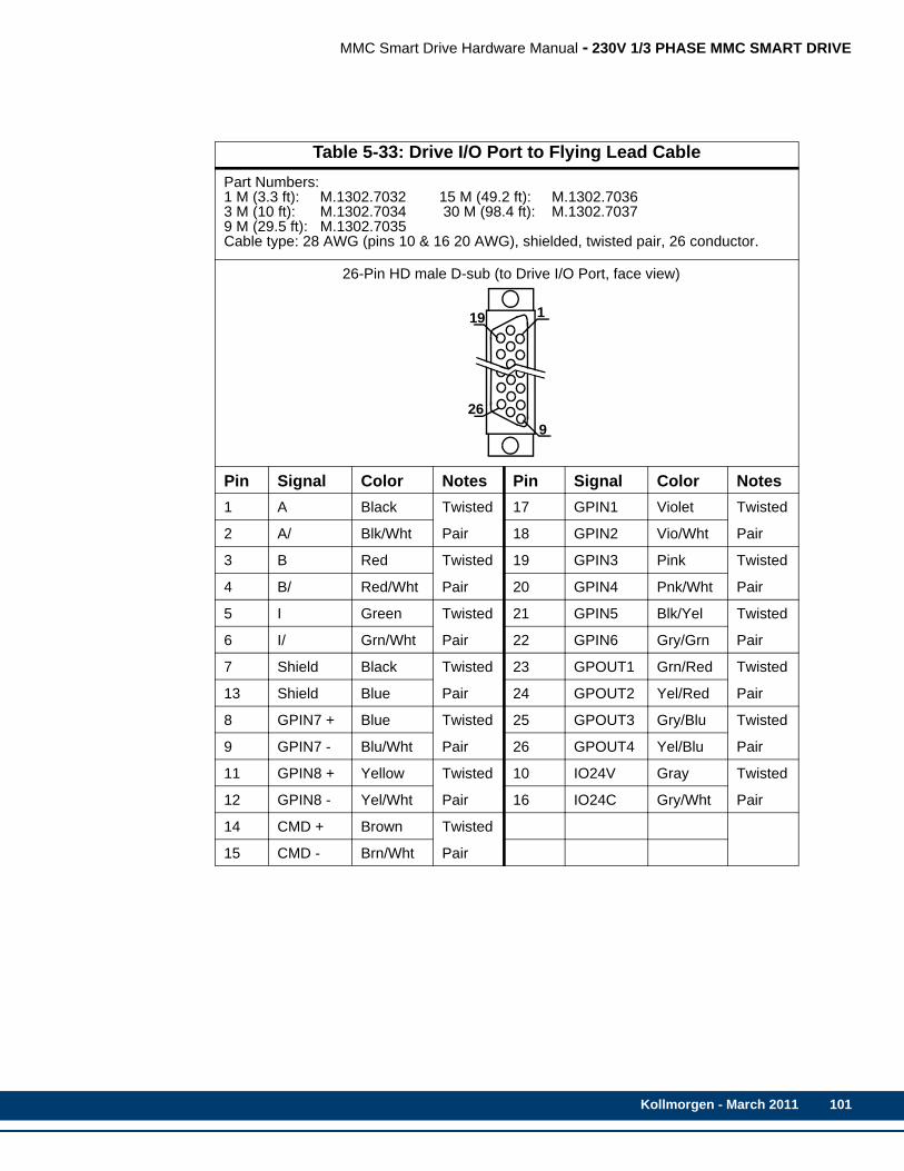
MMC Smart Drive Hardware Manual - 230V 1/3 PHASE MMC SMART DRIVE
Table 5-33: Drive I/O Port to Flying Lead CablePart Numbers:1 M (3.3 ft): M.1302.7032 15 M (49.2 ft): M.1302.70363 M (10 ft): M.1302.7034 30 M (98.4 ft): M.1302.70379 M (29.5 ft): M.1302.7035Cable type: 28 AWG (pins 10 & 16 20 AWG), shielded, twisted pair, 26 conductor.
26-Pin HD male D-sub (to Drive I/O Port, face view)
Pin Signal Color Notes Pin Signal Color Notes1 A Black Twisted 17 GPIN1 Violet Twisted
2 A/ Blk/Wht Pair 18 GPIN2 Vio/Wht Pair
3 B Red Twisted 19 GPIN3 Pink Twisted
4 B/ Red/Wht Pair 20 GPIN4 Pnk/Wht Pair
5 I Green Twisted 21 GPIN5 Blk/Yel Twisted
6 I/ Grn/Wht Pair 22 GPIN6 Gry/Grn Pair
7 Shield Black Twisted 23 GPOUT1 Grn/Red Twisted
13 Shield Blue Pair 24 GPOUT2 Yel/Red Pair
8 GPIN7 + Blue Twisted 25 GPOUT3 Gry/Blu Twisted
9 GPIN7 - Blu/Wht Pair 26 GPOUT4 Yel/Blu Pair
11 GPIN8 + Yellow Twisted 10 IO24V Gray Twisted
12 GPIN8 - Yel/Wht Pair 16 IO24C Gry/Wht Pair
14 CMD + Brown Twisted
15 CMD - Brn/Wht Pair
9
1
26
19
Kollmorgen - March 2011 101
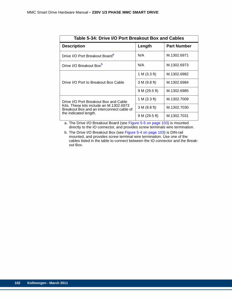
102
MMC Smart Drive Hardware Manual - 230V 1/3 PHASE MMC SMART DRIVE
Table 5-34: Drive I/O Port Breakout Box and CablesDescription Length Part Number
Drive I/O Port Breakout Boarda
a. The Drive I/O Breakout Board (see Figure 5-5 on page 103) is mounted directly to the IO connector, and provides screw terminals wire termination.
N/A M.1302.6971
Drive I/O Breakout Boxb
b. The Drive I/O Breakout Box (see Figure 5-4 on page 103) is DIN-rail mounted, and provides screw terminal wire termination. Use one of the cables listed in the table to connect between the IO connector and the Break-out Box.
N/A M.1302.6973
Drive I/O Port to Breakout Box Cable
1 M (3.3 ft) M.1302.6982
3 M (9.8 ft) M.1302.6984
9 M (29.5 ft) M.1302.6985
Drive I/O Port Breakout Box and Cable Kits. These kits include an M.1302.6973 Breakout Box and an interconnect cable of the indicated length.
1 M (3.3 ft) M.1302.7009
3 M (9.8 ft) M.1302.7030
9 M (29.5 ft) M.1302.7031
Kollmorgen - March 2011

MMC Smart Drive Hardware Manual - 230V 1/3 PHASE MMC SMART DRIVE
Figure 5-4: Drive I/O Port Breakout Box Dimensions
Figure 5-5: Drive I/O Port Breakout Board Dimensions
Kollmorgen - March 2011 103
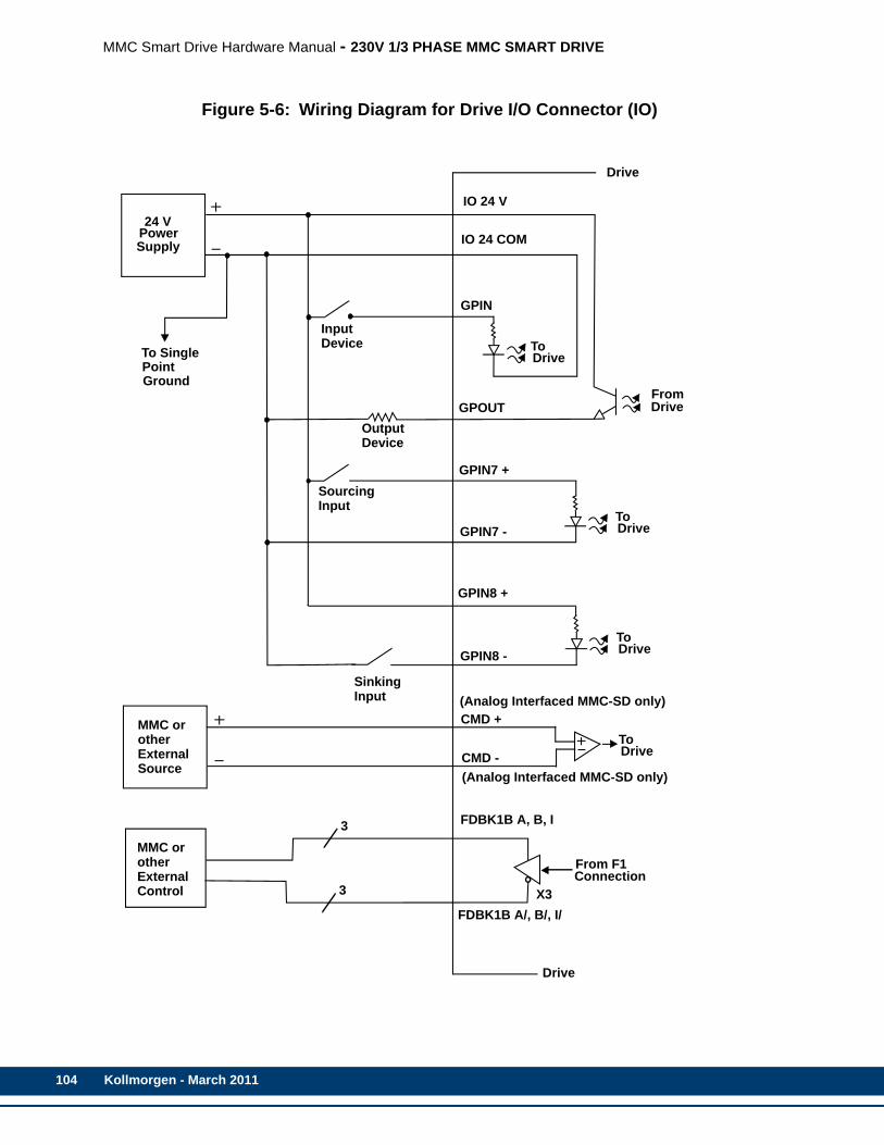
104
MMC Smart Drive Hardware Manual - 230V 1/3 PHASE MMC SMART DRIVE
Figure 5-6: Wiring Diagram for Drive I/O Connector (IO)
24 VPowerSupply
To SinglePointGround
GPIN
GPOUT
IO 24 COM
IO 24 V
ToDrive
FromDrive
ToDrive
GPIN7 +
GPIN7 -
InputDevice
OutputDevice
SourcingInput
GPIN8 +
GPIN8 -
SinkingInput
ToDrive
ToDrive
CMD +
CMD -
X3
From F1Connection
3
3
FDBK1B A, B, I
FDBK1B A/, B/, I/
MMC orotherExternalControl
MMC orotherExternalSource
Drive
Drive
(Analog Interfaced MMC-SD only)
(Analog Interfaced MMC-SD only)
Kollmorgen - March 2011
MMC Smart Drive Hardware Manual - 230V 1/3 PHASE MMC SMART DRIVE
5.2 Power Section ConnectorsThis section describes the connectors located on the Power Section (left portion) of the drive.
Kollmorgen - March 2011 105
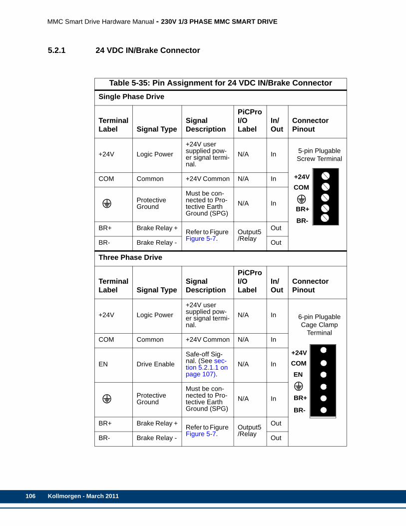
106
MMC Smart Drive Hardware Manual - 230V 1/3 PHASE MMC SMART DRIVE
5.2.1 24 VDC IN/Brake Connector
Table 5-35: Pin Assignment for 24 VDC IN/Brake ConnectorSingle Phase Drive
TerminalLabel Signal Type
Signal Description
PiCPro I/O Label
In/Out
Connector Pinout
+24V Logic Power+24V user supplied pow-er signal termi-nal.
N/A In 5-pin Plugable Screw Terminal
COM Common +24V Common N/A In
Protective Ground
Must be con-nected to Pro-tective Earth Ground (SPG)
N/A In
BR+ Brake Relay + Refer to Figure Figure 5-7.
Output5/Relay
Out
BR- Brake Relay - Out
Three Phase Drive
TerminalLabel Signal Type
Signal Description
PiCPro I/O Label
In/Out
Connector Pinout
+24V Logic Power+24V user supplied pow-er signal termi-nal.
N/A In 6-pin Plugable Cage Clamp
TerminalCOM Common +24V Common N/A In
EN Drive EnableSafe-off Sig-nal. (See sec-tion 5.2.1.1 on page 107).
N/A In
Protective Ground
Must be con-nected to Pro-tective Earth Ground (SPG)
N/A In
BR+ Brake Relay + Refer to Figure Figure 5-7.
Output5/Relay
Out
BR- Brake Relay - Out
+24VCOM
BR+
BR-
+24VCOM
BR+
BR-
EN
Kollmorgen - March 2011
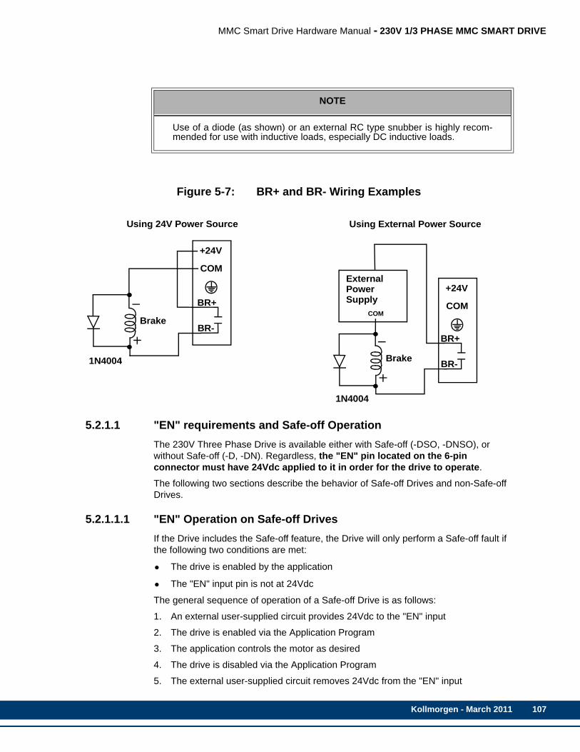
MMC Smart Drive Hardware Manual - 230V 1/3 PHASE MMC SMART DRIVE
Figure 5-7: BR+ and BR- Wiring Examples
5.2.1.1 "EN" requirements and Safe-off OperationThe 230V Three Phase Drive is available either with Safe-off (-DSO, -DNSO), or without Safe-off (-D, -DN). Regardless, the "EN" pin located on the 6-pin connector must have 24Vdc applied to it in order for the drive to operate.
The following two sections describe the behavior of Safe-off Drives and non-Safe-off Drives.
5.2.1.1.1 "EN" Operation on Safe-off DrivesIf the Drive includes the Safe-off feature, the Drive will only perform a Safe-off fault if the following two conditions are met:
• The drive is enabled by the application
• The "EN" input pin is not at 24Vdc
The general sequence of operation of a Safe-off Drive is as follows:
1. An external user-supplied circuit provides 24Vdc to the "EN" input
2. The drive is enabled via the Application Program
3. The application controls the motor as desired
4. The drive is disabled via the Application Program
5. The external user-supplied circuit removes 24Vdc from the "EN" input
NOTE
Use of a diode (as shown) or an external RC type snubber is highly recom-mended for use with inductive loads, especially DC inductive loads.
Using 24V Power Source
+24V
COM
BR+
BR-
Using External Power Source
Brake
+24V
COM
Brake
ExternalPowerSupply
COMBR+
BR-
1N4004
1N4004
Kollmorgen - March 2011 107

108
MMC Smart Drive Hardware Manual - 230V 1/3 PHASE MMC SMART DRIVE
6. The process is repeated starting with step 1 above as required
If during step 3 above, the user-supplied external circuitry removes 24Vdc from the "EN" input (usually due to a safety violation on the equipment being controlled), the drive will fault, and the motor will coast to a stop. The drive must be powered off and back on to remove the fault condition.
5.2.1.1.2 "EN" operation on non-Safe-off DrivesIf the Drive does not include the Safe-off feature, regardless of the sequence of operation, if the "EN" ever loses 24Vdc, the drive faults, and the motor coasts to a stop. The drive must be powered off and back on to remove the fault condition.
5.2.2 Power ConnectorThe Power Connector consists of a non-pluggable 9-pin screw-terminal block, and provides connection to the incoming AC power and the motor that is being controlled by the Drive.
ADDITIONAL SHUNT RESISTOR INFORMATION
Refer to section 4.5 on page 50 for instructions on choosing, mounting, andconnecting Shunt Resistors available from Kollmorgen.
Kollmorgen - March 2011

MMC Smart Drive Hardware Manual - 230V 1/3 PHASE MMC SMART DRIVE
Table 5-36: Pin Assignment for 1 Phase Drive Power ConnectorSingle Phase Drive
TerminalLabel Signal Type
Signal Description In/Out Pin Sequence
B+DC Bus
Power from drive to active shunt
Out
9-pin non-plugable Screw Terminal
B-
L1AC Power
100-240VAC single phase power in to drive.
InL2
Protective Ground
Must be con-nected to Pro-tective Earth Ground (SPG).
In
U
Motor Power
Power U-phase from the drive to the motor.
Out
VPower V-phase from the drive to the motor.
Out
WPower W-Phase from the drive to the mo-tor.
Out
Protective Ground
Connection for motor ground. In
W
V
U
L2L1
B-
B+
Kollmorgen - March 2011 109

110
MMC Smart Drive Hardware Manual - 230V 1/3 PHASE MMC SMART DRIVE
Table 5-37: Pin Assignment for 3 Phase Drive Power ConnectorThree Phase Drive
TerminalLabel Signal Type
Signal Description In/Out Pin Sequence
NC DC BusPower from drive to active shunt
N/A
9-pin non-plugable Screw Terminal
L1
AC Power100-240VAC single or three-phase power in to drive.
InL2
L3
Protective Ground
Must be con-nected to Pro-tective Earth Ground (SPG).
In
U
Motor Power
Power U-phase from the drive to the motor.
Out
VPower V-phase from the drive to the motor.
Out
WPower W-Phase from the drive to the mo-tor.
Out
Protective Ground
Connection for motor ground. In
SINGLE PHASE CONNECTION
If single-phase power is used, L1 must be connected to "hot", and L2 must beconnected to "neutral". L3 may remain unconnected.
W
V
U
L3L2
L1
NC
Kollmorgen - March 2011
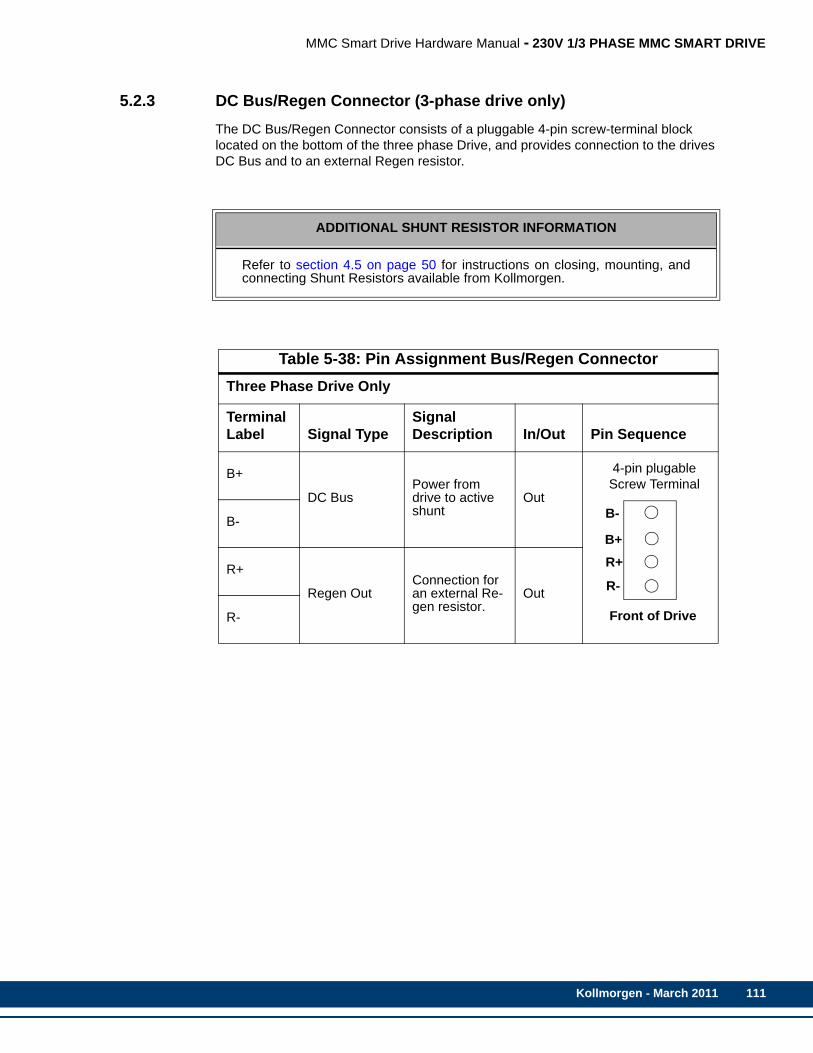
MMC Smart Drive Hardware Manual - 230V 1/3 PHASE MMC SMART DRIVE
5.2.3 DC Bus/Regen Connector (3-phase drive only)The DC Bus/Regen Connector consists of a pluggable 4-pin screw-terminal block located on the bottom of the three phase Drive, and provides connection to the drives DC Bus and to an external Regen resistor.
ADDITIONAL SHUNT RESISTOR INFORMATION
Refer to section 4.5 on page 50 for instructions on closing, mounting, andconnecting Shunt Resistors available from Kollmorgen.
Table 5-38: Pin Assignment Bus/Regen ConnectorThree Phase Drive Only
TerminalLabel Signal Type
Signal Description In/Out Pin Sequence
B+
DC BusPower from drive to active shunt
Out
4-pin plugable Screw Terminal
B-
R+
Regen OutConnection for an external Re-gen resistor.
Out
R-
B-
B+
R-
R+
Front of Drive
Kollmorgen - March 2011 111
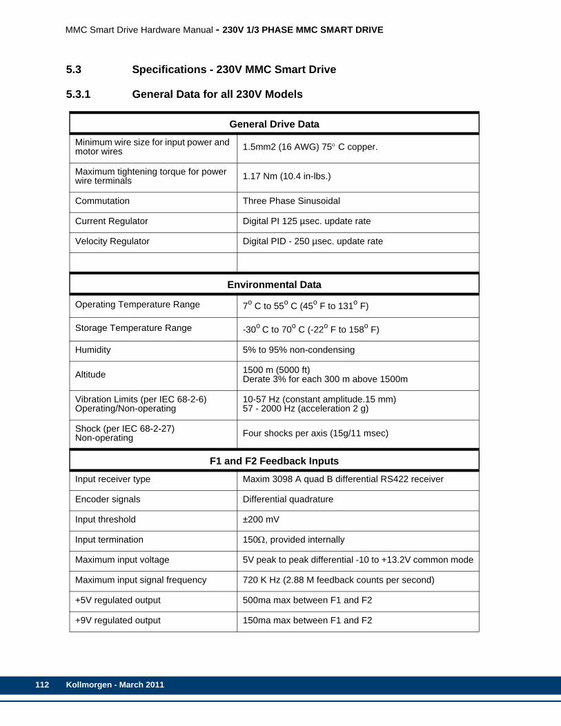
112
MMC Smart Drive Hardware Manual - 230V 1/3 PHASE MMC SMART DRIVE
5.3 Specifications - 230V MMC Smart Drive
5.3.1 General Data for all 230V Models
General Drive Data
Minimum wire size for input power and motor wires 1.5mm2 (16 AWG) 75° C copper.
Maximum tightening torque for power wire terminals 1.17 Nm (10.4 in-lbs.)
Commutation Three Phase Sinusoidal
Current Regulator Digital PI 125 µsec. update rate
Velocity Regulator Digital PID - 250 µsec. update rate
Environmental Data
Operating Temperature Range 7o C to 55o C (45o F to 131o F)
Storage Temperature Range -30o C to 70o C (-22o F to 158o F)
Humidity 5% to 95% non-condensing
Altitude 1500 m (5000 ft)Derate 3% for each 300 m above 1500m
Vibration Limits (per IEC 68-2-6)Operating/Non-operating
10-57 Hz (constant amplitude.15 mm)57 - 2000 Hz (acceleration 2 g)
Shock (per IEC 68-2-27)Non-operating Four shocks per axis (15g/11 msec)
F1 and F2 Feedback Inputs
Input receiver type Maxim 3098 A quad B differential RS422 receiver
Encoder signals Differential quadrature
Input threshold ±200 mV
Input termination 150Ω, provided internally
Maximum input voltage 5V peak to peak differential -10 to +13.2V common mode
Maximum input signal frequency 720 K Hz (2.88 M feedback counts per second)
+5V regulated output 500ma max between F1 and F2
+9V regulated output 150ma max between F1 and F2
Kollmorgen - March 2011
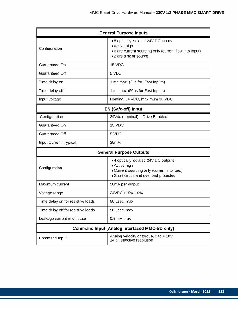
MMC Smart Drive Hardware Manual - 230V 1/3 PHASE MMC SMART DRIVE
General Purpose Inputs
Configuration
•8 optically isolated 24V DC inputs•Active high•6 are current sourcing only (current flow into input)•2 are sink or source
Guaranteed On 15 VDC
Guaranteed Off 5 VDC
Time delay on 1 ms max. (3us for Fast Inputs)
Time delay off 1 ms max (50us for Fast Inputs)
Input voltage Nominal 24 VDC, maximum 30 VDC
EN (Safe-off) Input
Configuration 24Vdc (nominal) = Drive Enabled
Guaranteed On 15 VDC
Guaranteed Off 5 VDC
Input Current, Typical 25mA.
General Purpose Outputs
Configuration
•4 optically isolated 24V DC outputs•Active high•Current sourcing only (current into load)•Short circuit and overload protected
Maximum current 50mA per output
Voltage range 24VDC +15%-10%
Time delay on for resistive loads 50 µsec. max
Time delay off for resistive loads 50 µsec. max
Leakage current in off state 0.5 mA max
Command Input (Analog Interfaced MMC-SD only)
Command Input Analog velocity or torque, 0 to + 10V14 bit effective resolution
Kollmorgen - March 2011 113

114
MMC Smart Drive Hardware Manual - 230V 1/3 PHASE MMC SMART DRIVE
Digital Link In/Out Ports (Digital Interfaced MMC-SD only)
“In” port Sends and receives high speed data to and from connect-ed MMC-SD’s “Out” port.
“Out” port Sends and receives high speed data to and from connect-ed MMC-SD’s “In” port.
Cable Type Shielded, Straight Pinned, CAT5 or better (CAT5e, CAT6, etc.)
Maximum Cable Length 30 m (98.4 ft)
Drive I/O Connector Encoder Emulation Output
F1 Motor Feedback TypeInput LimitEncoder Emulation Output(A quad B Differential Output)
Incremental Encoder720 KHz2.88 M counts/sec.The motor encoder A/B/I inputs are electrically buffered and retransmitted via the Drive I/O connector.
High Resolution Encoder
100 KHz400 K counts/sec.The encoder SIN/COS signals are electrically squared and retransmitted as A/B. The index mark “I” is synthe-sized by the drive control DSP. Absolute position informa-tion is not available via the Encoder Emulation Output.
Resolver
500 RPS2.00 M counts/sec.The field-installable resolver interface module converts the motor resolver to 1024 lines/4096 counts per revolu-tion of A/B encoder output. The module synthesizes the index mark “I” once per revolution of the resolver. Abso-lute position information is not available via the Encoder Emulation Output.
Conformity
CE Marked (only for Single Phase Drives. Three Phase Drives pending).
Conforms to Low Voltage Directive 73/23/EEC (amended by 93/68/EEC) and EMC Directive 89/336/EEC (amend-ed by 92/31/EEC and 93/68/EEC).Conformance is in accordance with the following stan-dards:EN 50178 and EN61800-3
UL and C/UL Listed E233454
Kollmorgen - March 2011

MMC Smart Drive Hardware Manual - 230V 1/3 PHASE MMC SMART DRIVE
5.3.2 Physical and Electrical Data for 230V Drives
Model
MMC-SD-0.5-230
MMC-SD-1.0-230
MMC-SD-2.0-230
MMC-SD-3.0-230
Part Numbersa
Analog (Standard Width) 1-phase, no BiSS 1(3)-phase, no BiSSDigital (-D,Standard Width) 1-phase, no BiSS 1-phase, Biss 1(3)-phase, no Safe Off 1(3)-phase, Safe OffDigital (-DN, Narrow Width) 1-phase, no BiSS 1-phase, Biss 1(3)-phase, no Safe Off 1(3)-phase, Safe Off
M.1302.5090M.3000.0929
M.1302.8130M.3000.0461M.3000.0911M.3000.0919
M.1302.8908M.3000.0458M.3000.0915M.3000.0922
M.1302.5091M.3000.0930
M.1302.8131M.3000.0462M.3000.0912M.3000.0920
M.1302.8910M.3000.0459M.3000.0916M.3000.0923
M.1302.5092M.3000.0931
M.1302.8132M.3000.0463M.3000.0913M.3000.0921
M.1302.8911M.3000.0460M.3000.0917M.3000.0924
Not AvailableNot Available
Not AvailableNot AvailableM.3000.0869M.3000.0946
Not AvailableNot AvailableM.3000.0868M.3000.0945
Weight, lbs (kg) 4.9 (2.23) 5.6 (2.55) 5.7 (2.59) 5.7 (2.59)
AC Input Specifications, 1-phase (3-phase)
Input Power (kVA) .5 (.5) 1.0 (1.0) 2.0 (2.0) 2.3 (3.0)
Input Voltage, VAC 100-240 (nominal), 88-265 (absolute limits)
Input Frequency, Hz 47 - 63
Nominal Input CurrentAmps RMS 5 (3) 9 (5) 18 (10) 18 (14)
Maximum InrushAmps 0-Peak 70 (70) 70 (70) 70 (70) 70 (70)
Power Loss, Watts 22 (22) 37 (37) 70 (70) 90 (90)
AC Output Specifications, 1-phase (3-phase)
Continuous Output Amps RMS Amps 0-Peak
1.8 (1.8)2.5 (2.5)
3.5 (3.5)5.0 (5.0)
7.1 (7.1)10 (10)
10.6 (10.6)15 (15)
Continuous Output Power 1-phase (3-phase)
Input = 115 VAC, W 250 (250) 500 (500) 1K (1K) 1.5K (1.5K)
Input = 230 VAC, W 500 (500) 1K (1K) 2K (2K) 2.3K (3K)
Peak Output Current Amps 0-Peak 7.5 (7.5) 15 (15) 30 (30) 30 (30)
Output Frequency, Hz 0-266 (0-266)
Kollmorgen - March 2011 115
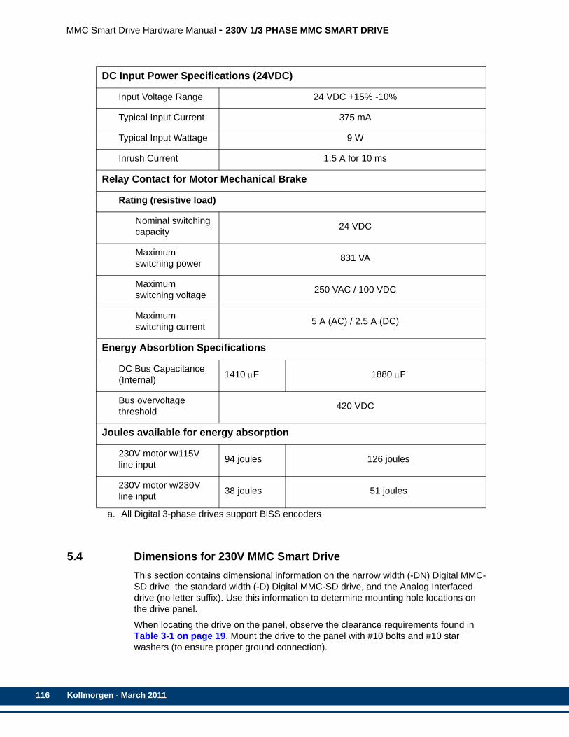
116
MMC Smart Drive Hardware Manual - 230V 1/3 PHASE MMC SMART DRIVE
5.4 Dimensions for 230V MMC Smart DriveThis section contains dimensional information on the narrow width (-DN) Digital MMC-SD drive, the standard width (-D) Digital MMC-SD drive, and the Analog Interfaced drive (no letter suffix). Use this information to determine mounting hole locations on the drive panel.
When locating the drive on the panel, observe the clearance requirements found in Table 3-1 on page 19. Mount the drive to the panel with #10 bolts and #10 star washers (to ensure proper ground connection).
DC Input Power Specifications (24VDC)
Input Voltage Range 24 VDC +15% -10%
Typical Input Current 375 mA
Typical Input Wattage 9 W
Inrush Current 1.5 A for 10 ms
Relay Contact for Motor Mechanical Brake
Rating (resistive load)
Nominal switching capacity 24 VDC
Maximum switching power 831 VA
Maximum switching voltage 250 VAC / 100 VDC
Maximum switching current 5 A (AC) / 2.5 A (DC)
Energy Absorbtion Specifications
DC Bus Capacitance (Internal) 1410 μF 1880 μF
Bus overvoltage threshold 420 VDC
Joules available for energy absorption
230V motor w/115V line input 94 joules 126 joules
230V motor w/230V line input 38 joules 51 joules
a. All Digital 3-phase drives support BiSS encoders
Kollmorgen - March 2011
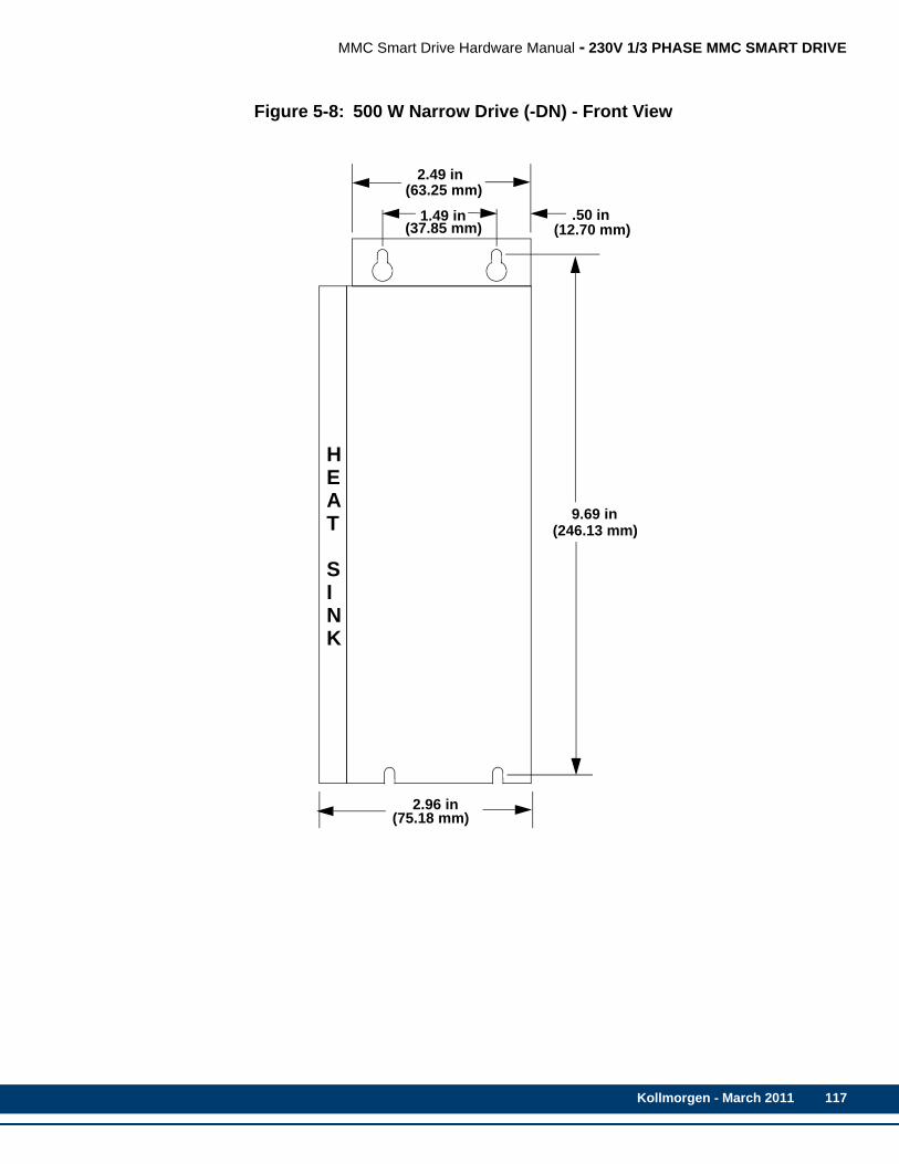
MMC Smart Drive Hardware Manual - 230V 1/3 PHASE MMC SMART DRIVE
Figure 5-8: 500 W Narrow Drive (-DN) - Front View
2.96 in(75.18 mm)
2.49 in(63.25 mm)
1.49 in(37.85 mm)
.50 in(12.70 mm)
9.69 in(246.13 mm)
HEAT
SINK
Kollmorgen - March 2011 117
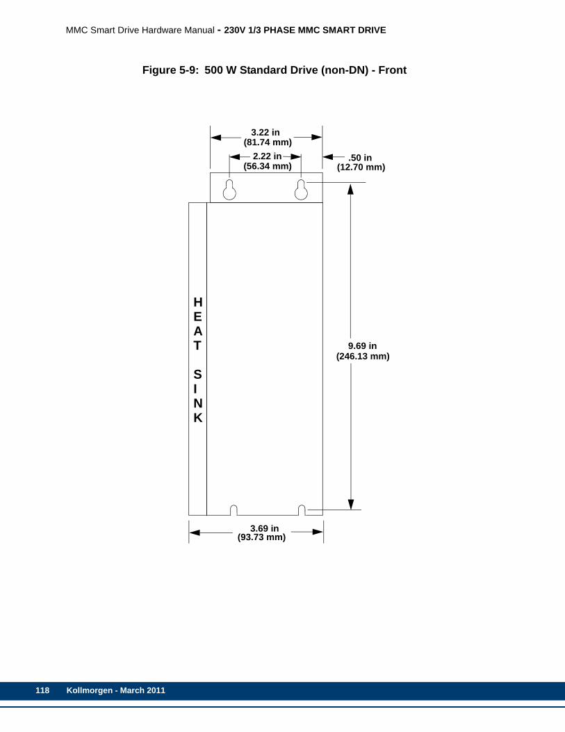
118
MMC Smart Drive Hardware Manual - 230V 1/3 PHASE MMC SMART DRIVE
Figure 5-9: 500 W Standard Drive (non-DN) - Front
3.69 in(93.73 mm)
3.22 in(81.74 mm)
2.22 in(56.34 mm)
.50 in(12.70 mm)
9.69 in(246.13 mm)
HEAT
SINK
Kollmorgen - March 2011

MMC Smart Drive Hardware Manual - 230V 1/3 PHASE MMC SMART DRIVE
Figure 5-10: 1, 2, and 3 kW Narrow Drive (-DN) - Front View
3.96 in(100.59 mm)
2.49 in(63.25 mm)
1.49 in(37.85 mm)
.50 in(12.70 mm)
9.69 in(246.13 mm)
HEAT
SINK
Kollmorgen - March 2011 119
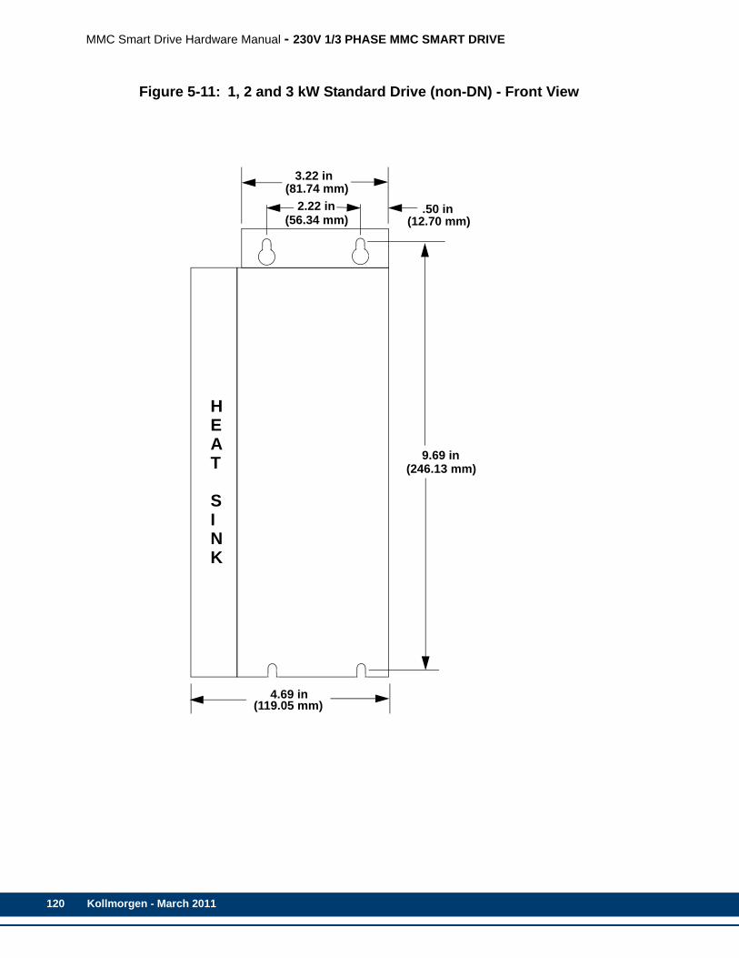
120
MMC Smart Drive Hardware Manual - 230V 1/3 PHASE MMC SMART DRIVE
Figure 5-11: 1, 2 and 3 kW Standard Drive (non-DN) - Front View
4.69 in(119.05 mm)
3.22 in(81.74 mm)
2.22 in(56.34 mm)
.50 in(12.70 mm)
9.69 in(246.13 mm)
HEAT
SINK
Kollmorgen - March 2011
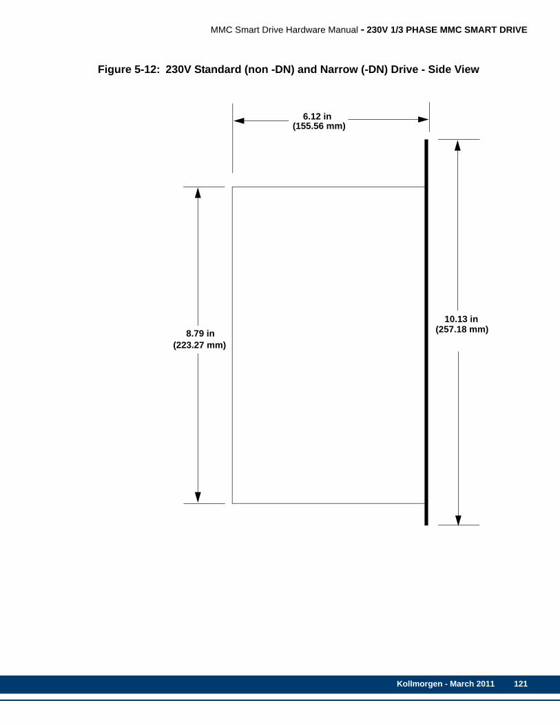
MMC Smart Drive Hardware Manual - 230V 1/3 PHASE MMC SMART DRIVE
Figure 5-12: 230V Standard (non -DN) and Narrow (-DN) Drive - Side View
6.12 in(155.56 mm)
8.79 in(223.27 mm)
10.13 in(257.18 mm)
Kollmorgen - March 2011 121

122
MMC Smart Drive Hardware Manual - 230V 1/3 PHASE MMC SMART DRIVE
Kollmorgen - March 2011
MMC Smart Drive Hardware Manual - 460V 3-PHASE MMC SMART DRIVE
6 460V 3-Phase MMC Smart DriveThe 460V MMC Smart Drive is available in both analog and digital interfaced versions, with power ratings from 1.3kW through 65kW. This section describes these drives in detail.
6.1 Control Section Connectors, Switches, LEDsThe Control Section is located on the right side of the drive, and is identical to the Control Section on the 230V Smart Drive. Refer to section 5.1 on page 69 for Information on the connectors, switches, and LEDs located on the Control Section of the drive.
6.2 Power Section ConnectorsThe 460V Smart Drive is available in four frame sizes (size 1 through 4). The Power Section connectors location and function are different among the four frame sizes. Each frame size is described in detail in the following sections.
6.2.1 Size 1 Power Section ConnectorsThis section describes in detail the connectors located on the Power Section of the Size 1 drives.
The functionality and descriptions for the switches and connectors on the Control Section of the 460V MMC Smart Drives are the same as those on the 230V MMC Smart Drive. Refer to section 5.1 on page 69 for more information.
Kollmorgen - March 2011 123
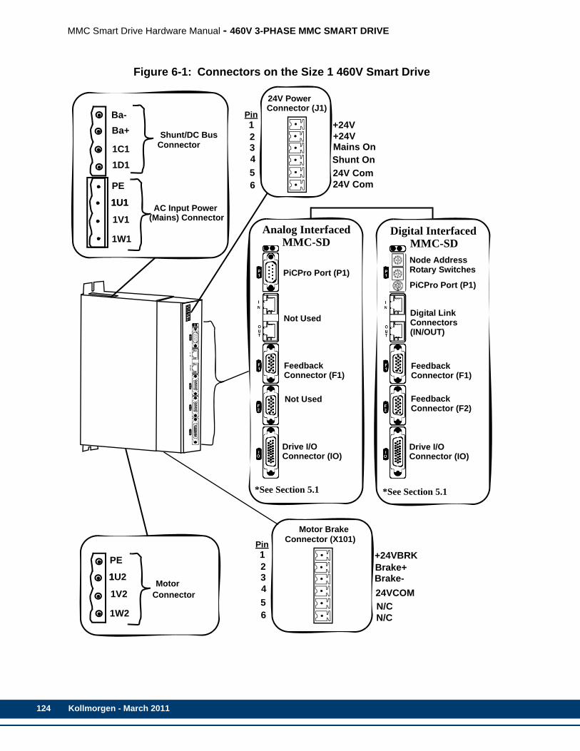
124
MMC Smart Drive Hardware Manual - 460V 3-PHASE MMC SMART DRIVE
Figure 6-1: Connectors on the Size 1 460V Smart Drive
Ba-Ba+
1C11D1
PE
1U1
1V1
1W1
1U1
Shunt/DC Bus
AC Input Power
Connector
PE
1U2
1V2
1W2
1Motor
Connector
PiCPro Port (P1)
FeedbackConnector (F1)
Drive I/OConnector (IO)
Motor Brake
24V PowerConnector (J1)
+24V+24VMains OnShunt On 24V Com 24V Com
Pin123456
Pin123456
Connector (X101)
(Mains) Connector
+24VBRKBrake+
24VCOMN/CN/C
Brake-
PiCPro Port (P1)
FeedbackConnector (F1)
Drive I/OConnector (IO)
FeedbackConnector (F2)
*See Section 5.1
Node AddressRotary Switches
Digital LinkConnectorsNot Used
*See Section 5.1
Analog Interfaced Digital Interfaced
(IN/OUT)
MMC-SD MMC-SD
Not Used
Kollmorgen - March 2011

MMC Smart Drive Hardware Manual - 460V 3-PHASE MMC SMART DRIVE
6.2.1.1 Shunt/DC Bus Connector
Table 6-1: 460V Size 1 Shunt/DC Bus Connector
Signal Type Signal DescriptionConnector Label In/Out Connector
PowerExternal Shunt Resis-tor. Used to dissipate energy returned to the drive by the motor.
Ba-Out
Ba+
DC Bus Pow-er
Direct DC bus con-nection
1C1 (ZK+)
N/A1D1 (ZK-)
Note: A 4-pin screw-terminal mating connector is included with the drive. Additional connectors (P/N M.1302.7159) are available from Kollmorgen.
NOTE
The shunt resistor (if installed) across Ba+ and Ba- will be connected acrossthe DC bus when the DC bus reaches the “shunt switch threshold” as shownin the specification table; or when the “Shunt On” input on the J1 connectoris active.
NOTE
If a 460V drive is connected to 220V to run a 220V motor, enable the “220VShunt on 440V Drive” feature using PiCPro, connect GPOUT3 on the DriveI/O (IO) connector to the “Shunt On” input on the J1 connector, and installthe appropriate shunt resistor across the Ba+ and Ba- terminals. The shuntresistor will be applied across the DC bus when the DC bus voltage risesabove 415 volts, and will be removed when the DC bus voltage falls below400 volts.
Ba-Ba+
1C11D1
Kollmorgen - March 2011 125

126
MMC Smart Drive Hardware Manual - 460V 3-PHASE MMC SMART DRIVE
6.2.1.2 AC Power Connector
6.2.1.3 Motor Connector
Table 6-2: 460V Size 1 AC Power Connector
Signal TypeSignal Description
Connector Label In/Out Connector
Protective Ground
Protective Earth Ground PE Out
Power
3 phase input power AC source must be center grounded Y sys-tem.
1U1
In1V1
1W1
Note: A 4-pin screw-terminal mating connector is included with the drive. Additional connectors (P/N M.1302.7158) are available from Kollmorgen.
Table 6-3: 460V Size 1 Motor ConnectorSignal Type Signal Description
Connector Label In/Out Connector
Protective Ground
Protective Earth Ground PE Out
Power Drive outputpower to motor.
1U2
Out1V2
1W2
Note: A 4-pin screw-terminal mating connector is included with the drive. Additional connectors (P/N M.1302.7159) are available from Kollmorgen.
PE1U1
1V11W1
PE1U2
1V21W2
Kollmorgen - March 2011
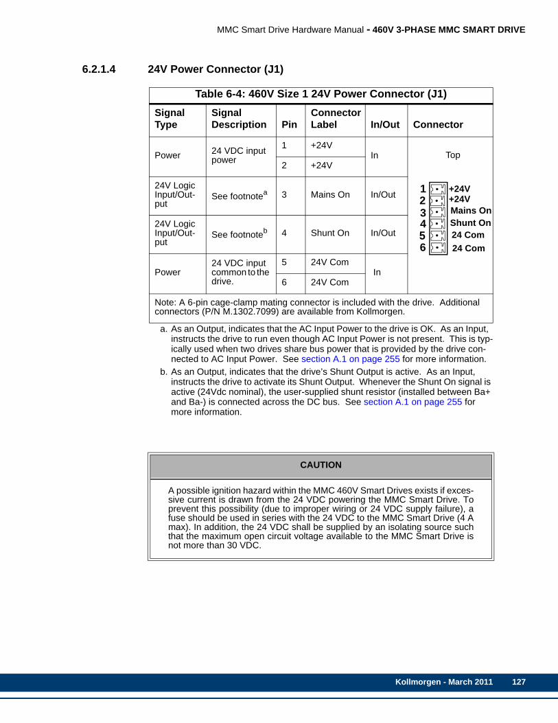
MMC Smart Drive Hardware Manual - 460V 3-PHASE MMC SMART DRIVE
6.2.1.4 24V Power Connector (J1)
Table 6-4: 460V Size 1 24V Power Connector (J1)Signal Type
Signal Description Pin
Connector Label In/Out Connector
Power 24 VDC input power
1 +24VIn Top
2 +24V
24V Logic Input/Out-put
See footnotea
a. As an Output, indicates that the AC Input Power to the drive is OK. As an Input, instructs the drive to run even though AC Input Power is not present. This is typ-ically used when two drives share bus power that is provided by the drive con-nected to AC Input Power. See section A.1 on page 255 for more information.
3 Mains On In/Out
24V LogicInput/Out-put
See footnoteb
b. As an Output, indicates that the drive’s Shunt Output is active. As an Input, instructs the drive to activate its Shunt Output. Whenever the Shunt On signal is active (24Vdc nominal), the user-supplied shunt resistor (installed between Ba+ and Ba-) is connected across the DC bus. See section A.1 on page 255 for more information.
4 Shunt On In/Out
Power24 VDC input common to the drive.
5 24V Com In
6 24V Com
Note: A 6-pin cage-clamp mating connector is included with the drive. Additional connectors (P/N M.1302.7099) are available from Kollmorgen.
CAUTION
A possible ignition hazard within the MMC 460V Smart Drives exists if exces-sive current is drawn from the 24 VDC powering the MMC Smart Drive. Toprevent this possibility (due to improper wiring or 24 VDC supply failure), afuse should be used in series with the 24 VDC to the MMC Smart Drive (4 Amax). In addition, the 24 VDC shall be supplied by an isolating source suchthat the maximum open circuit voltage available to the MMC Smart Drive isnot more than 30 VDC.
+24V+24VMains OnShunt On24 Com24 Com
123456
Kollmorgen - March 2011 127
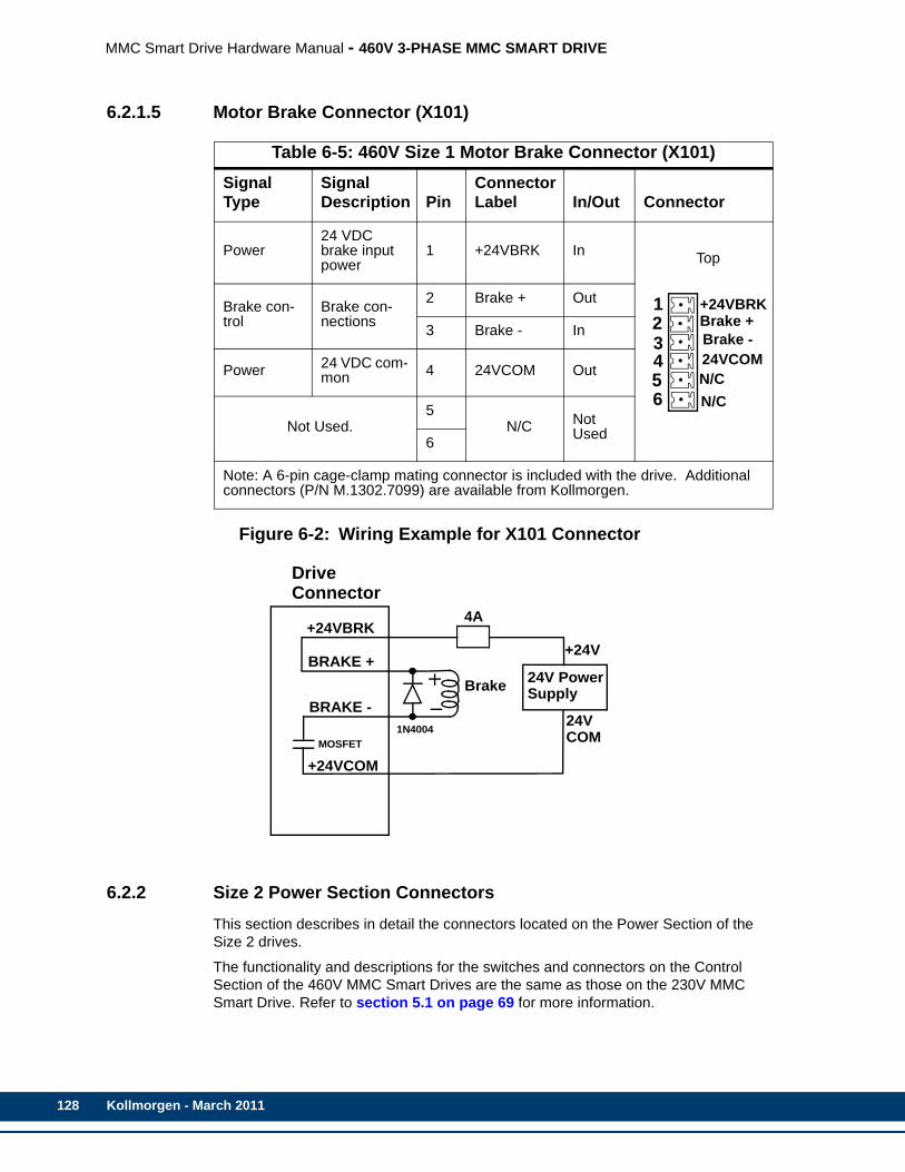
128
MMC Smart Drive Hardware Manual - 460V 3-PHASE MMC SMART DRIVE
6.2.1.5 Motor Brake Connector (X101)
Figure 6-2: Wiring Example for X101 Connector
6.2.2 Size 2 Power Section ConnectorsThis section describes in detail the connectors located on the Power Section of the Size 2 drives.
The functionality and descriptions for the switches and connectors on the Control Section of the 460V MMC Smart Drives are the same as those on the 230V MMC Smart Drive. Refer to section 5.1 on page 69 for more information.
Table 6-5: 460V Size 1 Motor Brake Connector (X101) Signal Type
Signal Description Pin
Connector Label In/Out Connector
Power24 VDC brake input power
1 +24VBRK In Top
Brake con-trol
Brake con-nections
2 Brake + Out
3 Brake - In
Power 24 VDC com-mon 4 24VCOM Out
Not Used.5
N/C Not Used6
Note: A 6-pin cage-clamp mating connector is included with the drive. Additional connectors (P/N M.1302.7099) are available from Kollmorgen.
+24VBRKBrake +Brake -24VCOMN/CN/C
123456
BRAKE -
+24VCOM
24V PowerSupplyBrake
24V
+24V
COM
DriveConnector
4A
BRAKE +
+24VBRK
MOSFET1N4004
Kollmorgen - March 2011
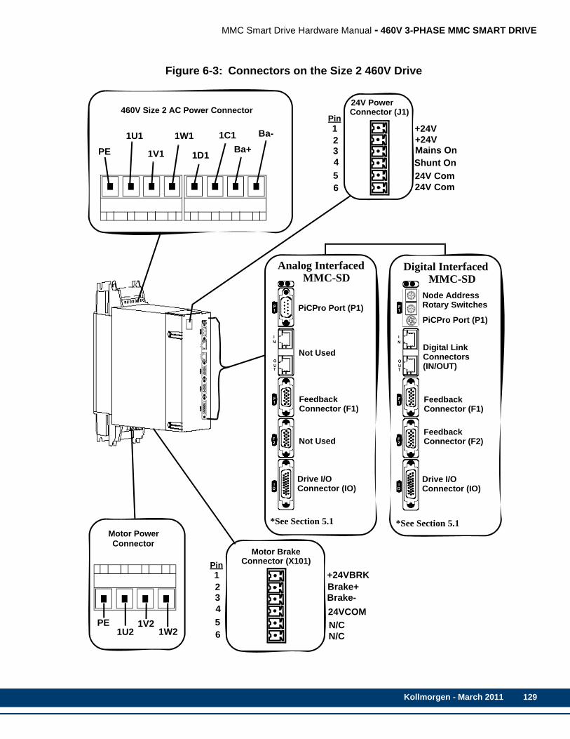
MMC Smart Drive Hardware Manual - 460V 3-PHASE MMC SMART DRIVE
Figure 6-3: Connectors on the Size 2 460V Drive
Ba-Ba+
1C1
1D1PE
460V Size 2 AC Power Connector
PE1U2
1V21W2
Motor PowerConnector
1U1
1V1
1W1
24V PowerConnector (J1)
+24V+24VMains OnShunt On 24V Com 24V Com
Pin123456
+24VBRKBrake+
24VCOM
Motor Brake
N/CN/C
Pin123456
Connector (X101)
Brake-
PiCPro Port (P1)
FeedbackConnector (F1)
Drive I/OConnector (IO)
Not Used
PiCPro Port (P1)
FeedbackConnector (F1)
Drive I/OConnector (IO)
FeedbackConnector (F2)
*See Section 5.1
Node AddressRotary Switches
Digital LinkConnectorsNot Used
*See Section 5.1
Analog Interfaced Digital Interfaced
(IN/OUT)
MMC-SD MMC-SD
Kollmorgen - March 2011 129

130
MMC Smart Drive Hardware Manual - 460V 3-PHASE MMC SMART DRIVE
6.2.2.1 AC Power Connector
Table 6-6: 460V Size 2 AC Power Connector
Signal Type Signal DescriptionConnector Label In/Out
Ground Protective Ground (Earth) PE Out
Power Three phase AC input power in to drive
1U1
In1V1
1W1
DC Bus Power Direct DC bus connec-tion
1D1 (ZK-)Out
1C1 (ZK+)
PowerExternal Shunt Resis-tor used to dissipate energy returned to the drive from motor
Ba+Out
Ba-
NOTE
The shunt resistor (if installed) across Ba+ and Ba- will be connected acrossthe DC bus when the DC bus reaches the “shunt switch threshold” as shownin the specification table; or when the “Shunt On” input on the J1 connectoris active.
NOTE
If a 460V drive is connected to 220V to run a 220V motor, enable the “220VShunt on 440V Drive” feature using PiCPro, connect GPOUT3 on the DriveI/O (IO) connector to the “Shunt On” input on the J1 connector, and installthe appropriate shunt resistor across the Ba+ and Ba- terminals. The shuntresistor will be applied across the DC bus when the DC bus voltage risesabove 415 volts, and will be removed when the DC bus voltage falls below400 volts.
Ba-Ba+
1C1
1D1PE1U1
1V1
1W1
Kollmorgen - March 2011
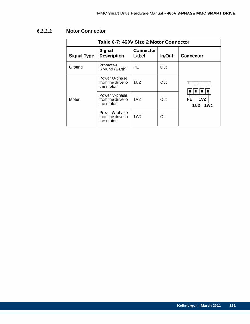
MMC Smart Drive Hardware Manual - 460V 3-PHASE MMC SMART DRIVE
6.2.2.2 Motor Connector
Table 6-7: 460V Size 2 Motor Connector
Signal TypeSignal Description
Connector Label In/Out Connector
Ground Protective Ground (Earth) PE Out
Motor
Power U-phase from the drive to the motor
1U2 Out
Power V-phase from the drive to the motor
1V2 Out
Power W-phase from the drive to the motor
1W2 Out
PE1U2
1V21W2
Kollmorgen - March 2011 131

132
MMC Smart Drive Hardware Manual - 460V 3-PHASE MMC SMART DRIVE
6.2.2.3 24V Power Connector (J1)
Table 6-8: 460V Size 2 24V Power Connector (J1)Signal Type
Signal Description Pin
Connector Label In/Out Connector
Power 24 VDC input power
1 +24VIn
2 +24V
24V Logic Input/Out-put
See footnotea
a. As an Output, indicates that the AC Input Power to the drive is OK. As an Input, instructs the drive to run even though AC Input Power is not present. This is typically used when two drives share bus power that is provided by the drive connected to AC Input Power. See section A.1 on page 255 for more informa-tion.
3 Mains On In/Out
24V LogicInput/Out-put
See footnoteb
b. As an Output, indicates that the drive’s Shunt Output is active. As an Input, instructs the drive to activate its Shunt Output. Whenever the Shunt On signal is active (24Vdc nominal), the user-supplied shunt resistor (installed between Ba+ and Ba-) is connected across the DC bus. See section A.1 on page 255 for more information.
4 Shunt On In/Out
Power24 VDC input common to the drive.
5 24V Com In
6 24V Com
Note: A 6-pin cage-clamp mating connector is included with the drive. Additional connectors (P/N M.1302.7099) are available from Kollmorgen.
CAUTION
A possible ignition hazard within the MMC 460V Smart Drives exists if exces-sive current is drawn from the 24 VDC powering the MMC Smart Drive. Toprevent this possibility (due to improper wiring or 24 VDC supply failure), afuse should be used in series with the 24 VDC to the MMC Smart Drive. Spe-cifically, a 4 A max. “UL248 Series” fuse should be used. In addition, the 24VDC shall be supplied by an isolating source such that the maximum opencircuit voltage available to the MMC Smart Drive is not more than 30 VDC.
+24V+24VMains OnShunt On24 Com24 Com
Top
123456
Kollmorgen - March 2011
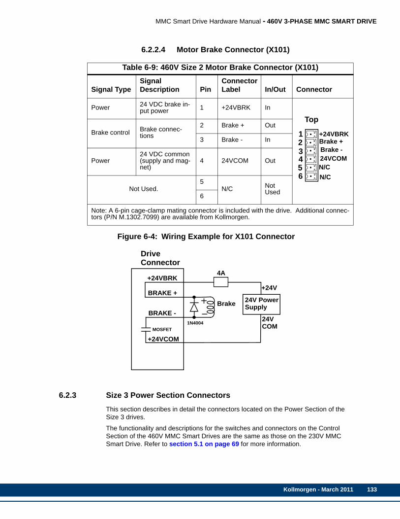
MMC Smart Drive Hardware Manual - 460V 3-PHASE MMC SMART DRIVE
6.2.2.4 Motor Brake Connector (X101)
Figure 6-4: Wiring Example for X101 Connector
6.2.3 Size 3 Power Section ConnectorsThis section describes in detail the connectors located on the Power Section of the Size 3 drives.
The functionality and descriptions for the switches and connectors on the Control Section of the 460V MMC Smart Drives are the same as those on the 230V MMC Smart Drive. Refer to section 5.1 on page 69 for more information.
Table 6-9: 460V Size 2 Motor Brake Connector (X101)
Signal TypeSignal Description Pin
Connector Label In/Out Connector
Power 24 VDC brake in-put power 1 +24VBRK In
Brake control Brake connec-tions
2 Brake + Out
3 Brake - In
Power24 VDC common (supply and mag-net)
4 24VCOM Out
Not Used.5
N/C Not Used6
Note: A 6-pin cage-clamp mating connector is included with the drive. Additional connec-tors (P/N M.1302.7099) are available from Kollmorgen.
+24VBRKBrake +Brake -24VCOMN/CN/C
Top
123456
BRAKE -
+24VCOM
24V PowerSupplyBrake
24V
+24V
COM
DriveConnector
4A
BRAKE +
+24VBRK
MOSFET1N4004
Kollmorgen - March 2011 133

134
MMC Smart Drive Hardware Manual - 460V 3-PHASE MMC SMART DRIVE
Figure 6-5: Connectors on the Size 3 460V Drive
Ba-Ba+
1C1
1D1PE
Line Power Connector
PE 1U21V2
1W2
Motor Power Connector
1U11V1
1W124V PowerConnector (J1)
+24V+24VMains OnShunt On 24V Com 24V Com
Pin123456
Motor BrakePin123456
Connector (X101)+24VBRKBrake+
24VCOMN/CN/C
Brake-
(Located under cover)
PE
PiCPro Port (P1)
FeedbackConnector (F1)
Drive I/OConnector (IO)
Not Used
PiCPro Port (P1)
FeedbackConnector (F1)
Drive I/OConnector (IO)
FeedbackConnector (F2)
*See Section 5.1
Node AddressRotary Switches
Digital LInkConnectorsNot Used
*See Section 5.1
Analog Interfaced Digital Interfaced
(IN/OUT)
MMC-SD MMC-SD
Kollmorgen - March 2011

MMC Smart Drive Hardware Manual - 460V 3-PHASE MMC SMART DRIVE
6.2.3.1 AC Power Connector
Table 6-10: 460V Size 3 AC Power Connector
Signal Type Signal DescriptionConnector Label In/Out
Ground Protective Ground (Earth) PE Out
Power Three phase AC input power in to drive
1U1
In1V1
1W1
DC Bus Power Direct DC bus connec-tion
1D1 (ZK-)Out
1C1 (ZK+)
External Shunt Resis-tor used to dissipate energy returned to the drive from motor
Ba+Out
Ba-
NOTE
The shunt resistor (if installed) across Ba+ and Ba- will be connected acrossthe DC bus when the DC bus reaches the “shunt switch threshold” as shownin the specification table; or when the “Shunt On” input on the J1 connectoris active.
NOTE
If a 460V drive is connected to 220V to run a 220V motor, enable the “220VShunt on 440V Drive” feature using PiCPro, connect GPOUT3 on the DriveI/O (IO) connector to the “Shunt On” input on the J1 connector, and installthe appropriate shunt resistor across the Ba+ and Ba- terminals. The shuntresistor will be applied across the DC bus when the DC bus voltage risesabove 415 volts, and will be removed when the DC bus voltage falls below400 volts.
Ba-Ba+
1C1
1D1PE1U1
1V1
1W1 PE
Kollmorgen - March 2011 135

136
MMC Smart Drive Hardware Manual - 460V 3-PHASE MMC SMART DRIVE
6.2.3.2 Motor Connector
Table 6-11: 460V Size 3 Motor ConnectorSignal Type
Signal Description
Connector Label In/Out Connector
Ground Protective Ground (Earth) PE Out
Motor
Power U-phase from the drive to the motor
1U2 Out
Power V-phase from the drive to the motor
1V2 Out
Power W-phase from the drive to the motor
1W2 Out
PE1U2
1V21W2
Kollmorgen - March 2011

MMC Smart Drive Hardware Manual - 460V 3-PHASE MMC SMART DRIVE
6.2.3.3 24V Power Connector (J1)
Table 6-12: 460V Size 3 24V Power Connector (J1)Signal Type
Signal Description Pin
Connector Label In/Out Connector
Power 24 VDC input power
1 +24VIn
2 +24V
24V Logic Input/Out-put
See footnotea
a. As an Output, indicates that the AC Input Power to the drive is OK. As an Input, instructs the drive to run even though AC Input Power is not present. This is typ-ically used when two drives share bus power that is provided by the drive con-nected to AC Input Power. See section A.1 on page 255 for more information.
3 Mains On In/Out
24V LogicInput/Out-put
See footnoteb
b. As an Output, indicates that the drive’s Shunt Output is active. As an Input, instructs the drive to activate its Shunt Output. Whenever the Shunt On signal is active (24Vdc nominal), the user-supplied shunt resistor (installed between Ba+ and Ba-) is connected across the DC bus. See section A.1 on page 255 for more information.
4 Shunt On In/Out
Power24 VDC input common to the drive.
5 24V Com In
6 24V Com
Note: A 6-pin cage-clamp mating connector is included with the drive. Additional connectors (P/N M.1302.7099) are available from Kollmorgen.
CAUTION
A possible ignition hazard within the MMC 460V Smart Drives exists if exces-sive current is drawn from the 24 VDC powering the MMC Smart Drive. Toprevent this possibility (due to improper wiring or 24 VDC supply failure), afuse should be used in series with the 24 VDC to the MMC Smart Drive. Spe-cifically, a 4 A max. “UL248 Series” fuse should be used. In addition, the 24VDC shall be supplied by an isolating source such that the maximum opencircuit voltage available to the MMC Smart Drive is not more than 30 VDC.
+24V+24VMains OnShunt On24 Com24 Com
Top
123456
Kollmorgen - March 2011 137

138
MMC Smart Drive Hardware Manual - 460V 3-PHASE MMC SMART DRIVE
6.2.3.4 Motor Brake Connector (X101)
Figure 6-6: Wiring Example for X101 Connector
6.2.4 Size 4 Power Section ConnectorsThis section describes in detail the connectors located on the Power Section of the Size 4 drives.
The functionality and descriptions for the switches and connectors on the Control Section of the 460V MMC Smart Drives are the same as those on the 230V MMC Smart Drive. Refer to section 5.1 on page 69 for more information.
Table 6-13: 460V Size 3 Motor Brake Connector (X101)
Signal TypeSignal Description Pin
Connector Label In/Out Connector
Power 24 VDC brake in-put power 1 +24VBRK In
Brake control Brake connec-tions
2 Brake + Out
3 Brake - In
Power24 VDC common (supply and mag-net)
4 24VCOM Out
Not Used.5
N/C Not Used6
Note: A 6-pin cage-clamp mating connector is included with the drive. Additional connec-tors (P/N M.1302.7099) are available from Kollmorgen.
+24VBRKBrake +Brake -24VCOMN/CN/C
Top
123456
BRAKE -
+24VCOM
24V PowerSupplyBrake
24V
+24V
COM
DriveConnector
4A
BRAKE +
+24VBRK
MOSFET1N4004
Kollmorgen - March 2011
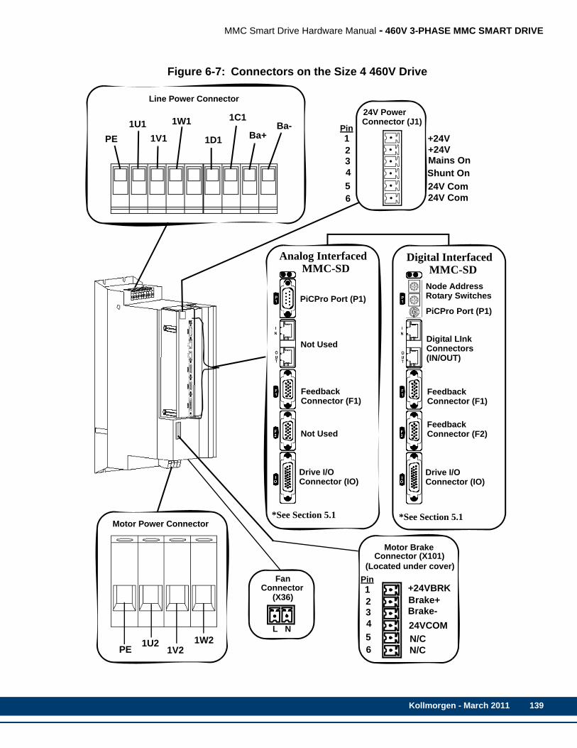
MMC Smart Drive Hardware Manual - 460V 3-PHASE MMC SMART DRIVE
Figure 6-7: Connectors on the Size 4 460V Drive
Ba-Ba+
1C1
1D1PE
Line Power Connector
PE 1U21V2
1W2
Motor Power Connector
1U11V1
1W124V PowerConnector (J1)
+24V+24VMains OnShunt On 24V Com 24V Com
Pin123456
Motor Brake
Pin123456
Connector (X101)
+24VBRKBrake+
24VCOMN/CN/C
Brake-
(Located under cover)
PiCPro Port (P1)
FeedbackConnector (F1)
Drive I/OConnector (IO)
Not Used
PiCPro Port (P1)
FeedbackConnector (F1)
Drive I/OConnector (IO)
FeedbackConnector (F2)
*See Section 5.1
Node AddressRotary Switches
Digital LInkConnectorsNot Used
*See Section 5.1
Analog Interfaced Digital Interfaced
(IN/OUT)
MMC-SD MMC-SD
FanConnector
(X36)
L N
Kollmorgen - March 2011 139
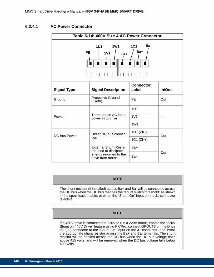
140
MMC Smart Drive Hardware Manual - 460V 3-PHASE MMC SMART DRIVE
6.2.4.1 AC Power Connector
Table 6-14: 460V Size 4 AC Power Connector
Signal Type Signal DescriptionConnector Label In/Out
Ground Protective Ground (Earth) PE Out
Power Three phase AC input power in to drive
1U1
In1V1
1W1
DC Bus Power Direct DC bus connec-tion
1D1 (ZK-)Out
1C1 (ZK+)
External Shunt Resis-tor used to dissipate energy returned to the drive from motor
Ba+Out
Ba-
NOTE
The shunt resistor (if installed) across Ba+ and Ba- will be connected acrossthe DC bus when the DC bus reaches the “shunt switch threshold” as shownin the specification table; or when the “Shunt On” input on the J1 connectoris active.
NOTE
If a 460V drive is connected to 220V to run a 220V motor, enable the “220VShunt on 440V Drive” feature using PiCPro, connect GPOUT3 on the DriveI/O (IO) connector to the “Shunt On” input on the J1 connector, and installthe appropriate shunt resistor across the Ba+ and Ba- terminals. The shuntresistor will be applied across the DC bus when the DC bus voltage risesabove 415 volts, and will be removed when the DC bus voltage falls below400 volts.
Ba-Ba+
1C1
1D1PE1U1
1V1
1W1
Kollmorgen - March 2011
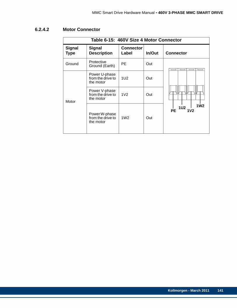
MMC Smart Drive Hardware Manual - 460V 3-PHASE MMC SMART DRIVE
6.2.4.2 Motor Connector
Table 6-15: 460V Size 4 Motor ConnectorSignal Type
Signal Description
Connector Label In/Out Connector
Ground Protective Ground (Earth) PE Out
Motor
Power U-phase from the drive to the motor
1U2 Out
Power V-phase from the drive to the motor
1V2 Out
Power W-phase from the drive to the motor
1W2 Out
PE1U2
1V21W2
Kollmorgen - March 2011 141
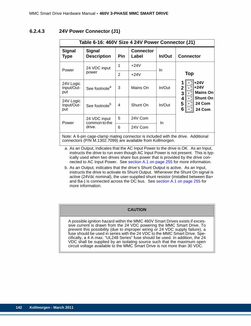
142
MMC Smart Drive Hardware Manual - 460V 3-PHASE MMC SMART DRIVE
6.2.4.3 24V Power Connector (J1)
Table 6-16: 460V Size 4 24V Power Connector (J1)Signal Type
Signal Description Pin
Connector Label In/Out Connector
Power 24 VDC input power
1 +24VIn
2 +24V
24V Logic Input/Out-put
See footnotea
a. As an Output, indicates that the AC Input Power to the drive is OK. As an Input, instructs the drive to run even though AC Input Power is not present. This is typ-ically used when two drives share bus power that is provided by the drive con-nected to AC Input Power. See section A.1 on page 255 for more information.
3 Mains On In/Out
24V LogicInput/Out-put
See footnoteb
b. As an Output, indicates that the drive’s Shunt Output is active. As an Input, instructs the drive to activate its Shunt Output. Whenever the Shunt On signal is active (24Vdc nominal), the user-supplied shunt resistor (installed between Ba+ and Ba-) is connected across the DC bus. See section A.1 on page 255 for more information.
4 Shunt On In/Out
Power24 VDC input common to the drive.
5 24V Com In
6 24V Com
Note: A 6-pin cage-clamp mating connector is included with the drive. Additional connectors (P/N M.1302.7099) are available from Kollmorgen.
CAUTION
A possible ignition hazard within the MMC 460V Smart Drives exists if exces-sive current is drawn from the 24 VDC powering the MMC Smart Drive. Toprevent this possibility (due to improper wiring or 24 VDC supply failure), afuse should be used in series with the 24 VDC to the MMC Smart Drive. Spe-cifically, a 4 A max. “UL248 Series” fuse should be used. In addition, the 24VDC shall be supplied by an isolating source such that the maximum opencircuit voltage available to the MMC Smart Drive is not more than 30 VDC.
+24V+24VMains OnShunt On24 Com24 Com
Top
123456
Kollmorgen - March 2011
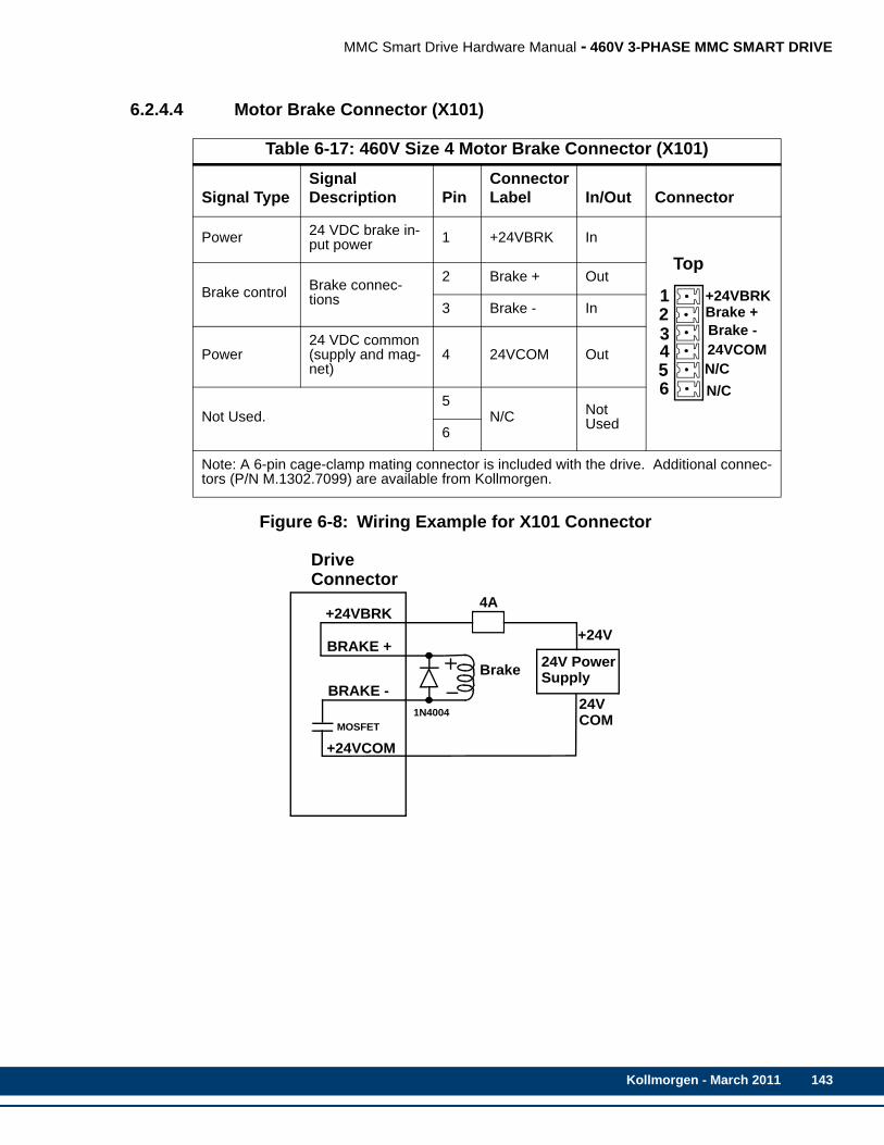
MMC Smart Drive Hardware Manual - 460V 3-PHASE MMC SMART DRIVE
6.2.4.4 Motor Brake Connector (X101)
Figure 6-8: Wiring Example for X101 Connector
Table 6-17: 460V Size 4 Motor Brake Connector (X101)
Signal TypeSignal Description Pin
Connector Label In/Out Connector
Power 24 VDC brake in-put power 1 +24VBRK In
Brake control Brake connec-tions
2 Brake + Out
3 Brake - In
Power24 VDC common (supply and mag-net)
4 24VCOM Out
Not Used.5
N/C Not Used6
Note: A 6-pin cage-clamp mating connector is included with the drive. Additional connec-tors (P/N M.1302.7099) are available from Kollmorgen.
+24VBRKBrake +Brake -24VCOMN/CN/C
Top
123456
BRAKE -
+24VCOM
24V PowerSupplyBrake
24V
+24V
COM
DriveConnector
4A
BRAKE +
+24VBRK
MOSFET1N4004
Kollmorgen - March 2011 143
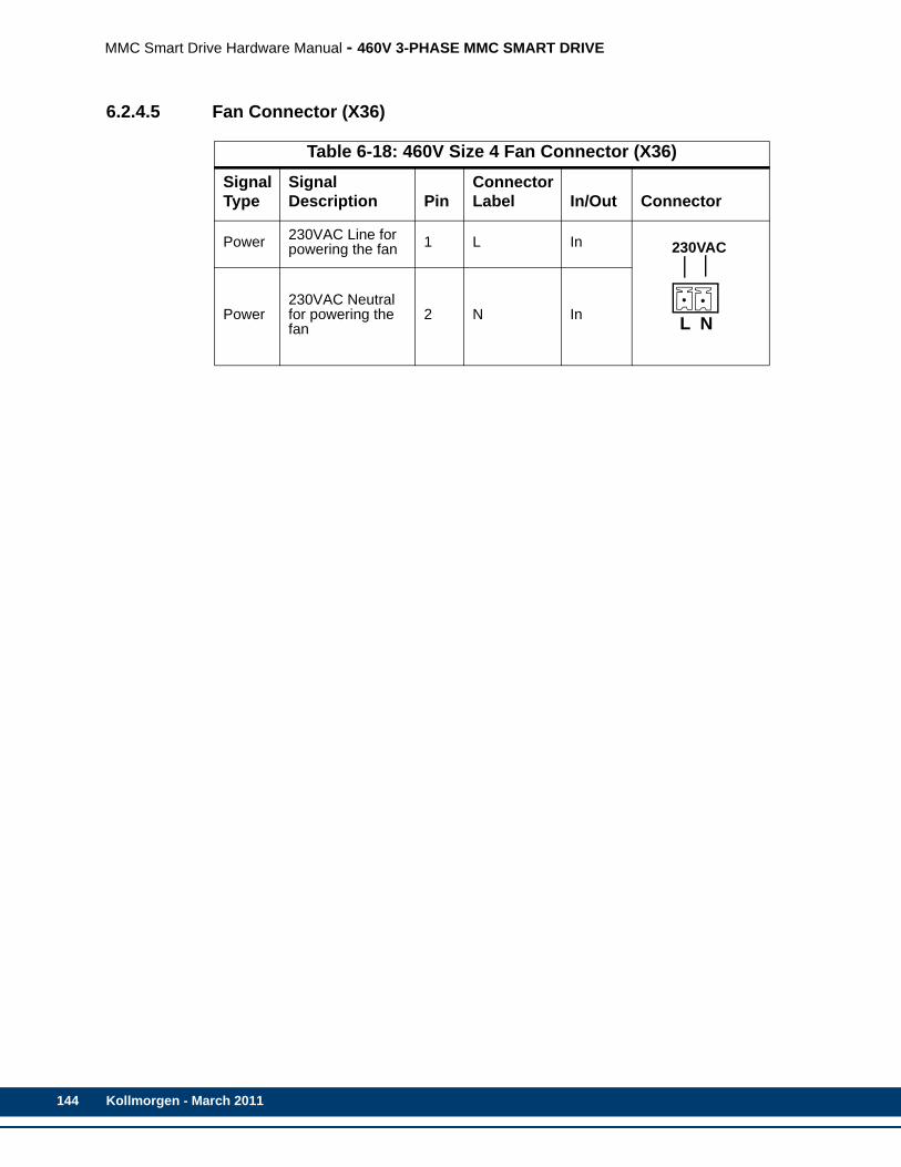
144
MMC Smart Drive Hardware Manual - 460V 3-PHASE MMC SMART DRIVE
6.2.4.5 Fan Connector (X36)
Table 6-18: 460V Size 4 Fan Connector (X36) Signal Type
Signal Description Pin
Connector Label In/Out Connector
Power 230VAC Line for powering the fan 1 L In
Power230VAC Neutral for powering the fan
2 N In
230VAC
NL
Kollmorgen - March 2011
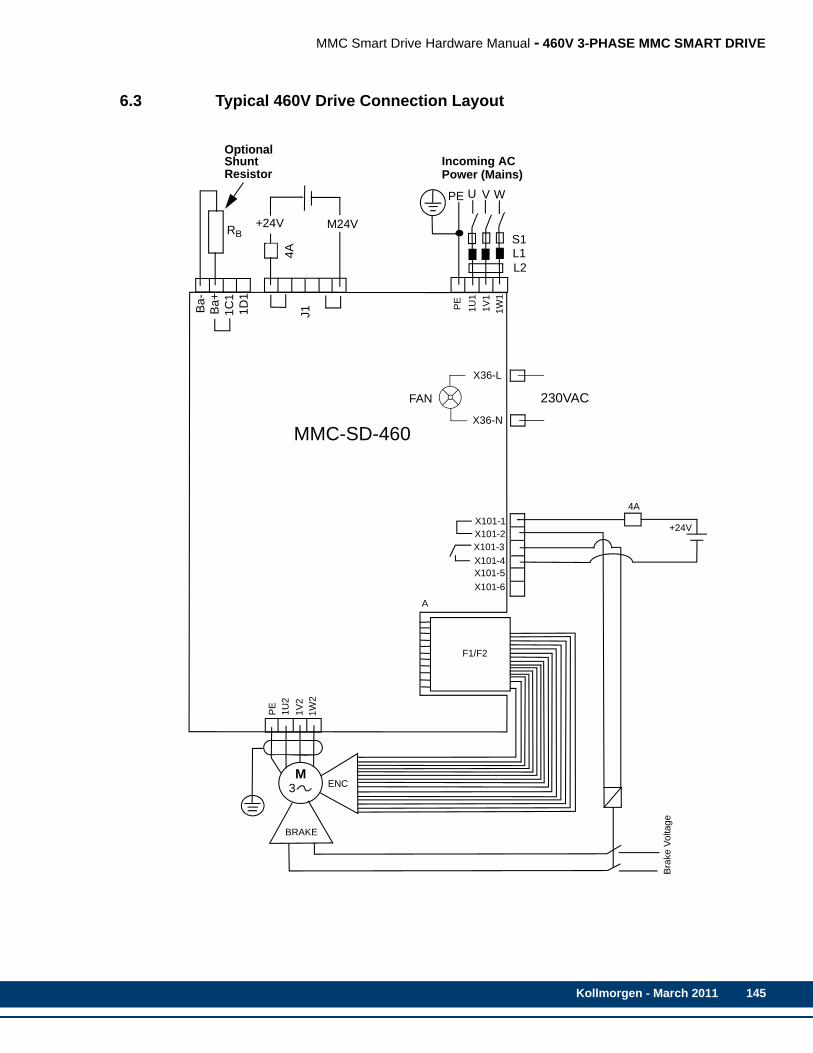
MMC Smart Drive Hardware Manual - 460V 3-PHASE MMC SMART DRIVE
6.3 Typical 460V Drive Connection Layout
Ba-
Ba+
1C1
1D1
J1
+24V M24V
4A
PE U V W
S1L1L2
RB
PE
1U1
1V1
1W1
X101-1X101-2X101-3X101-4X101-5X101-6
4A
+24V
Bra
ke V
olta
ge
BRAKE
ENC
PE
1U2
1V2
1W2
A
F1/F2
M3
MMC-SD-460
OptionalShuntResistor
Incoming ACPower (Mains)
230VAC
X36-L
FAN
X36-N
Kollmorgen - March 2011 145

146
MMC Smart Drive Hardware Manual - 460V 3-PHASE MMC SMART DRIVE
6.4 Specifications - 460V MMC Smart Drive)
6.4.1 Common Data for Size 1, 2, 3, 4 (All Models)
General Drive Data
Minimum wire size for input power wires 1.5mm2 (16 AWG) 75° C copper
Maximum tightening torque for pow-er wire terminals 1.25Nm (11 in-lbs.)
Commutation 3 Phase Sinusoidal, Space Vector Modulated (SVM)
Current Regulator Digital PI 125 µsec update rate
Velocity Regulator Digital PID - 250 µsec update rate
General Operating Data
Operating Temperature Range(MMC-SD-1.3, -2.4, -4.0, -6.0, -8.0, -12.0, -16.0, -24.0)
7o C to 50o C (45o F to 122o F)
Operating Temperature Range(MMC-SD-30.0, -42.0, -51.0, -65.0)
7o C to 55o C (45o F to 131o F). Derate 3% pero C above 40oC.
Storage Temperature Range -30o C to 70o C (-22o F to 158o F)
Humidity 5% to 95% non-condensing
Altitude 1500m (5000ft)Derate 3% for each 300 m above 1500m
Vibration Limits (per IEC 68-2-6)Operating/Non-operating
10-57Hz (constant amplitude .15mm)57 - 2000Hz (acceleration 2g)
Shock (per IEC 68-2-27)Non-operating 15g/11msec per axis
F1 and F2 Feedback Inputs
Input receiver type Maxim 3098 A quad B differential RS422 receiver
Encoder signals Differential quadrature
Input threshold ±200mV
Input termination 150Ω, provided internal
Maximum input voltage 5Vpp differential -10 to +13.2V common mode
Maximum input signal frequency 720KHz (2.88 M feedback unit count rate)
Kollmorgen - March 2011

MMC Smart Drive Hardware Manual - 460V 3-PHASE MMC SMART DRIVE
General Purpose Inputs
Configuration
•8 optically isolated 24V DC inputs•Active high•6 are current sourcing only (current flow into input)•2 are sink or source
Guaranteed On 15VDC
Guaranteed Off 5VDC
Time delay on 1ms max.
Time delay off 1ms max.
Input voltage Nominal 24VDC, maximum 30VDC
General Purpose Outputs
Configuration
•4 optically isolated 24VDC outputs•Active high•Current sourcing only (current into load)•Short circuit and overload protected
Maximum current 50mA per output
Voltage range 24VDC +15%-10%
Time delay on for resistive loads 50µsec. max
Time delay off for resistive loads 50µsec. max
Leakage current in off state 0.5mA max
Command Input/Output
Command Input Analog velocity or torque, 0 to + 10V14 bit effective resolution
Digital Link In/Out Ports (Digital Interfaced MMC-SD only)
“In” port Sends and receives high speed data to and from connected MMC-SD’s “Out” port.
“Out” port Sends and receives high speed data to and from connected MMC-SD’s “In” port.
Cable Type Shielded, Straight Pinned, CAT5 or better (CAT5e, CAT6, etc.)
Maximum Cable Length 30m (98.4 ft)
Kollmorgen - March 2011 147
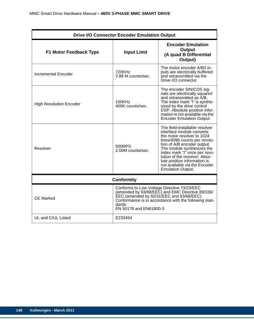
148
MMC Smart Drive Hardware Manual - 460V 3-PHASE MMC SMART DRIVE
Drive I/O Connector Encoder Emulation Output
F1 Motor Feedback Type Input LimitEncoder Emulation
Output(A quad B Differential
Output)
Incremental Encoder 720KHz2.88 M counts/sec.
The motor encoder A/B/I in-puts are electrically buffered and retransmitted via the Drive I/O connector.
High Resolution Encoder 100KHz400K counts/sec.
The encoder SIN/COS sig-nals are electrically squared and retransmitted as A/B. The index mark “I” is synthe-sized by the drive control DSP. Absolute position infor-mation is not available via the Encoder Emulation Output.
Resolver 500RPS2.00M counts/sec.
The field-installable resolver interface module converts the motor resolver to 1024 lines/4096 counts per revolu-tion of A/B encoder output. The module synthesizes the index mark “I” once per revo-lution of the resolver. Abso-lute position information is not available via the Encoder Emulation Output.
Conformity
CE Marked
Conforms to Low Voltage Directive 73/23/EEC (amended by 93/68/EEC) and EMC Directive 89/336/EEC (amended by 92/31/EEC and 93/68/EEC).Conformance is in accordance with the following stan-dards:EN 50178 and EN61800-3
UL and C/UL Listed E233454
Kollmorgen - March 2011

MMC Smart Drive Hardware Manual - 460V 3-PHASE MMC SMART DRIVE
6.4.2 Physical/Electrical Data for 460V Size 1 Smart Drives
Model
MMC-SD-1.3-460 (-D) MMC-SD-2.4-460 (-D)
Part NumbersAnalogDigital, no BiSSDigital, BiSS
M.1302.5093M.1302.8133M.3000.0464
M.1302.5094M.1302.8134M.3000.0465
Physical
Weight 10 lbs.
Electrical Specifications
AC Input Specifications
Input ConfigurationIndustrial system with direct low impedance earthed star point (TN or TT mains). Do not use with IT mains or corner grounded delta.
Inductance .4% (min) to 4% (max)
Nominal Input Power 1.94kVA 3.33kVA
Input Voltage 207-528 VAC (400 VAC nominal), 3 Phase
Input Frequency 47-63Hz
Nominal Input 2.44A RMS 4.18A RMS
NOTE: Nominal Input Current is specified for nominal input voltage of 460 VAC.
Maximum Inrush 4.56A RMS 7.81A RMS
Power Loss 34W 60W
AC Output SpecificationsContinuous Output Current RMS (0-Peak)
2.1A (3.0A) 3.9A (5.5A)
Continuous Output Power
Input = 230 VAC .65kW 1.2kW
Input = 460 VAC 1.3kW 2.4kW
Peak Output Current(0-Peak) 6.0A 11.0A
Output Frequency 0-450Hz
DC Input Power Specifications (24VDC)Input Voltage Range 24VDC +15% -10%
Typical Input Current 700mA
Typical Input Wattage 17W
Inrush Current 4A for 10ms
Kollmorgen - March 2011 149
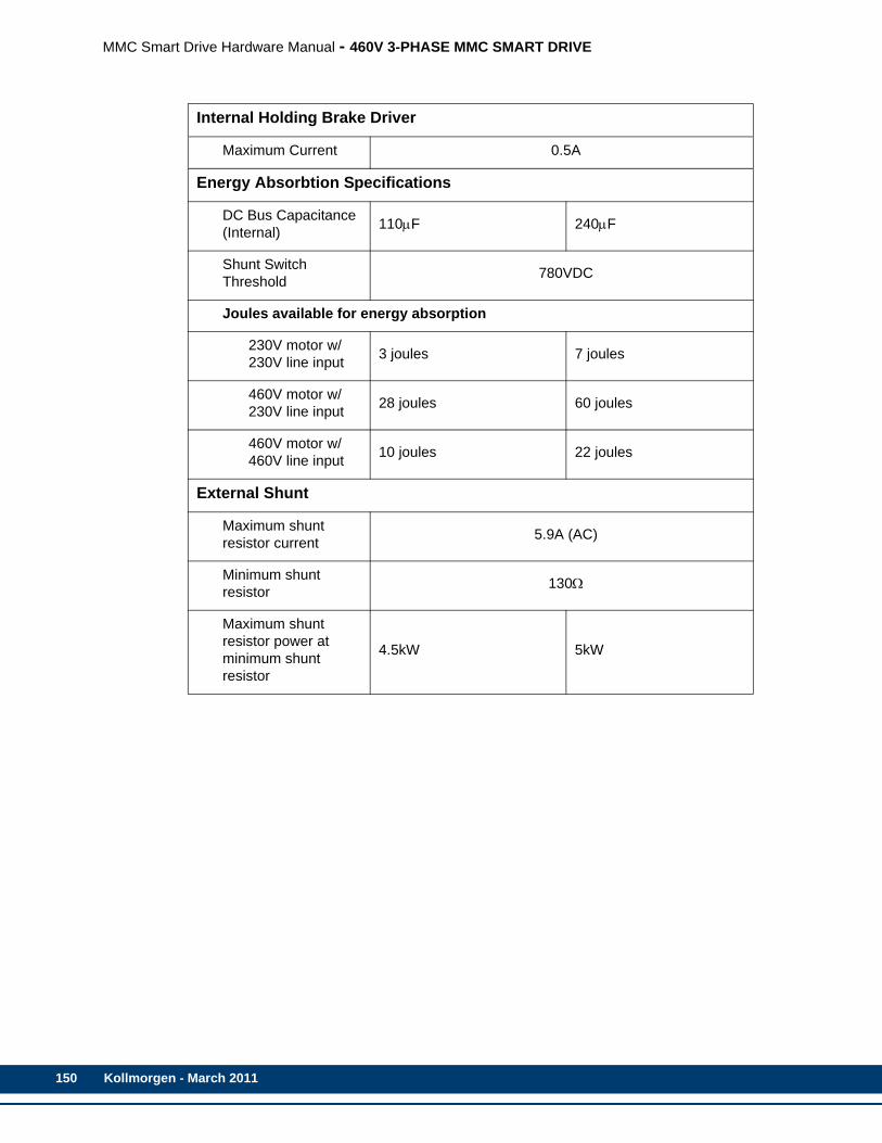
150
MMC Smart Drive Hardware Manual - 460V 3-PHASE MMC SMART DRIVE
Internal Holding Brake Driver
Maximum Current 0.5A
Energy Absorbtion Specifications
DC Bus Capacitance (Internal) 110μF 240μF
Shunt Switch Threshold 780VDC
Joules available for energy absorption
230V motor w/230V line input 3 joules 7 joules
460V motor w/230V line input 28 joules 60 joules
460V motor w/460V line input 10 joules 22 joules
External Shunt
Maximum shunt resistor current 5.9A (AC)
Minimum shunt resistor 130Ω
Maximum shunt resistor power at minimum shunt resistor
4.5kW 5kW
Kollmorgen - March 2011
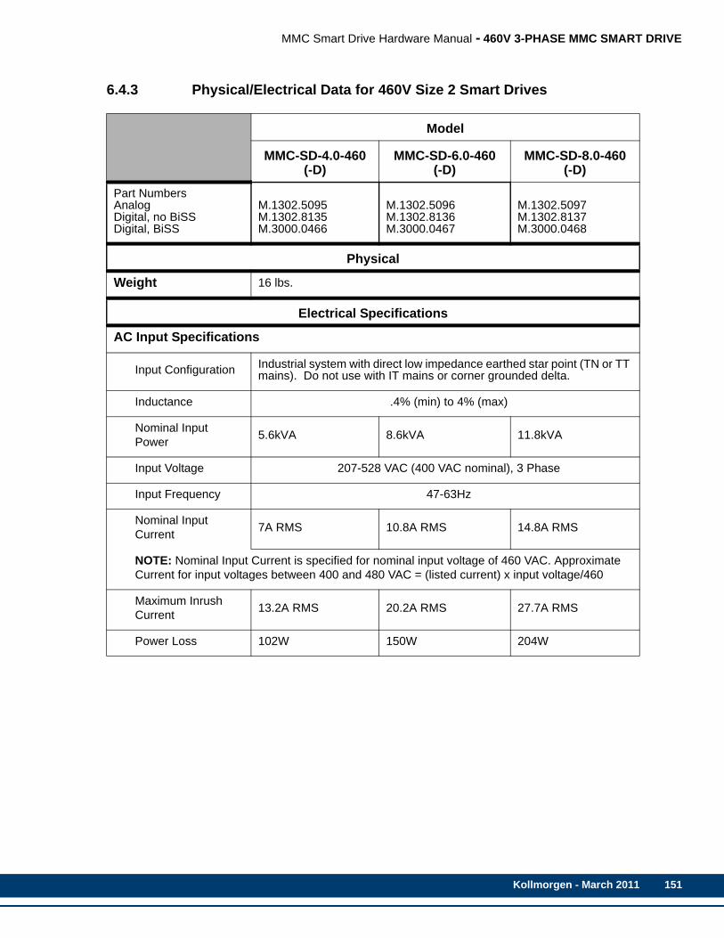
MMC Smart Drive Hardware Manual - 460V 3-PHASE MMC SMART DRIVE
6.4.3 Physical/Electrical Data for 460V Size 2 Smart Drives
Model
MMC-SD-4.0-460 (-D)
MMC-SD-6.0-460 (-D)
MMC-SD-8.0-460 (-D)
Part NumbersAnalogDigital, no BiSSDigital, BiSS
M.1302.5095M.1302.8135M.3000.0466
M.1302.5096M.1302.8136M.3000.0467
M.1302.5097M.1302.8137M.3000.0468
Physical
Weight 16 lbs.
Electrical Specifications
AC Input Specifications
Input Configuration Industrial system with direct low impedance earthed star point (TN or TT mains). Do not use with IT mains or corner grounded delta.
Inductance .4% (min) to 4% (max)
Nominal Input Power 5.6kVA 8.6kVA 11.8kVA
Input Voltage 207-528 VAC (400 VAC nominal), 3 Phase
Input Frequency 47-63Hz
Nominal Input Current 7A RMS 10.8A RMS 14.8A RMS
NOTE: Nominal Input Current is specified for nominal input voltage of 460 VAC. Approximate Current for input voltages between 400 and 480 VAC = (listed current) x input voltage/460
Maximum Inrush Current 13.2A RMS 20.2A RMS 27.7A RMS
Power Loss 102W 150W 204W
Kollmorgen - March 2011 151

152
MMC Smart Drive Hardware Manual - 460V 3-PHASE MMC SMART DRIVE
AC Output Specifications
Continuous Output Current RMS (0-Peak)
6.4A (9.0A) 9.6A (13.5A) 12.7A (18.0A)
Continuous Output Power
Input = 230 VAC 2.0kW 3.0kW 4.0kW
Input = 460 VAC 4.0kW 6.0kW 8.0kW
Peak Output Current(0-peak) 18.0A 27.0A 36.0A
Output Frequency 0Hz to 450Hz
Internal Holding Brake Driver
Maximum Current 0.5A
DC Input Power Specifications (24VDC)
Input Voltage Range 24VDC +15% -10%
Typical Input Current 1050mA
Typical Input Wattage 25W
Inrush Current 4A for 10ms
Energy Absorbtion Specifications
DC Bus Capacitance (Internal) 470μF 705μF
Shunt Switch Threshold 780VDC
Joules available for energy absorption
230V motor w/230V line input 13 joules 19 joules
460V motor w/230V line input 188 joules 177 joules
460V motor w/460V line input 44 joules 66 joules
Kollmorgen - March 2011

MMC Smart Drive Hardware Manual - 460V 3-PHASE MMC SMART DRIVE
External Shunt
Maximum shunt resistor current 9A (AC) 9A (AC) 9A (AC)
Minimum shunt resistor 86Ω 60Ω 44Ω
Maximum shunt resistor power at minimum shunt resistor
7kW 10kW 14kW
Kollmorgen - March 2011 153

154
MMC Smart Drive Hardware Manual - 460V 3-PHASE MMC SMART DRIVE
6.4.4 Physical/Electrical Data for 460V Size 3 Smart Drives
Model
MMC-SD-12.0-460
(-D)
MMC-SD-16.0-460
(-D)
MMC-SD-24.0-460
(-D)MMC-SD-
30.0-460-D
Part NumbersAnalogDigital, no BiSSDigital, BiSS
M.1302.5098M.1302.8138M.3000.0469
M.1302.5099M.1302.8139M.3000.0470
M.1302.5100M.1302.8140M.3000.0471
M.3000.0545N/AM.3000.0021
Physical
Weight 35 lbs.
Electrical Specifications
AC Input Specifications
Input ConfigurationIndustrial system with direct low impedance earthed star point (TN or TT mains). Do not use with IT mains or corner grounded delta.
Inductance 2.4% (min) to 4% (max)
Nominal Input Power 13.3kVA 16.8kVA 26.3 kVA 36.7 kVA
Input Voltage 207-528 VAC (400 VAC nominal), 3 Phase
Input Frequency 47-63Hz
Nominal Input Current 16.7A RMS 21.1A RMS 33.1A RMS 44.0A RMS
NOTE: Nominal Input Current is specified for nominal input voltage of 460 VAC. Approximate Current for input voltages between 400 and 480 VAC = (listed current) x 460/input voltage
Maximum Inrush Current 32.2A RMS 39.2A RMS 61.8A RMS tbdA RMS
Power Loss 300W 390W 600W 840W
Kollmorgen - March 2011
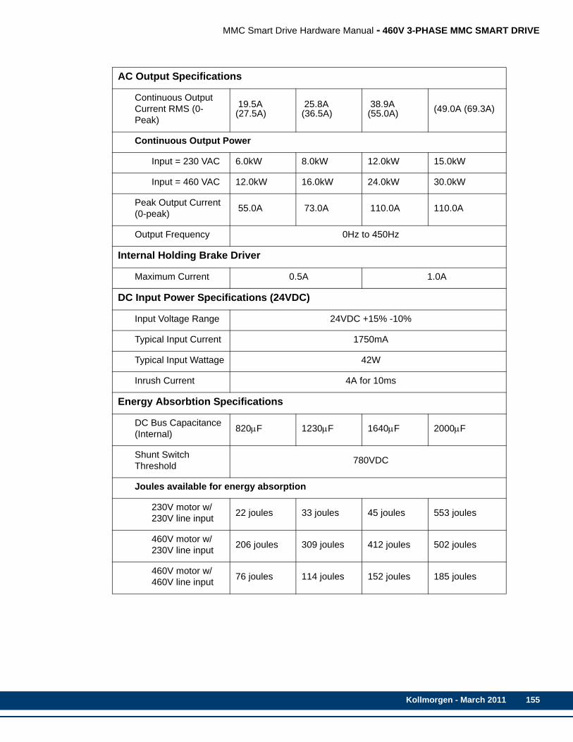
MMC Smart Drive Hardware Manual - 460V 3-PHASE MMC SMART DRIVE
AC Output Specifications
Continuous Output Current RMS (0-Peak)
19.5A (27.5A)
25.8A (36.5A)
38.9A (55.0A) (49.0A (69.3A)
Continuous Output Power
Input = 230 VAC 6.0kW 8.0kW 12.0kW 15.0kW
Input = 460 VAC 12.0kW 16.0kW 24.0kW 30.0kW
Peak Output Current(0-peak) 55.0A 73.0A 110.0A 110.0A
Output Frequency 0Hz to 450Hz
Internal Holding Brake Driver
Maximum Current 0.5A 1.0A
DC Input Power Specifications (24VDC)
Input Voltage Range 24VDC +15% -10%
Typical Input Current 1750mA
Typical Input Wattage 42W
Inrush Current 4A for 10ms
Energy Absorbtion Specifications
DC Bus Capacitance (Internal) 820μF 1230μF 1640μF 2000μF
Shunt Switch Threshold 780VDC
Joules available for energy absorption
230V motor w/230V line input 22 joules 33 joules 45 joules 553 joules
460V motor w/230V line input 206 joules 309 joules 412 joules 502 joules
460V motor w/460V line input 76 joules 114 joules 152 joules 185 joules
Kollmorgen - March 2011 155
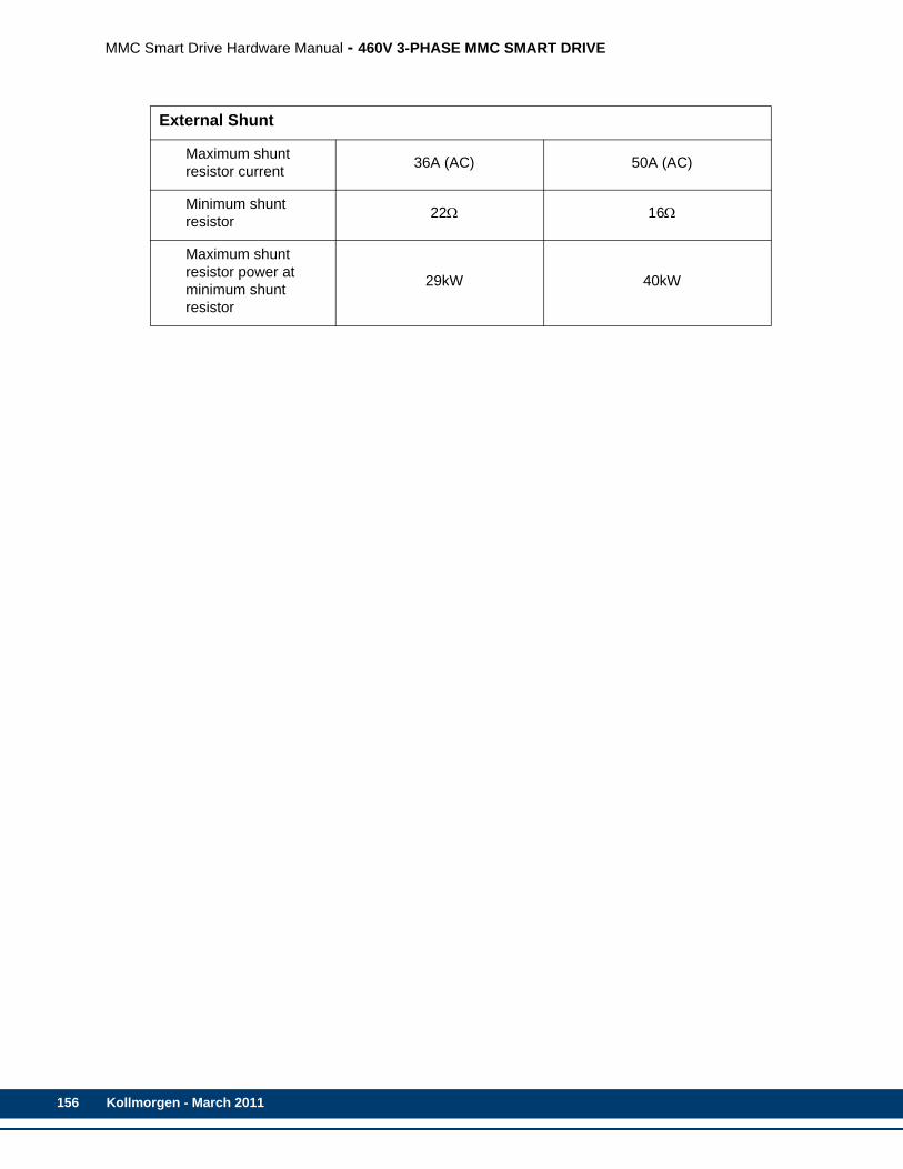
156
MMC Smart Drive Hardware Manual - 460V 3-PHASE MMC SMART DRIVE
External Shunt
Maximum shunt resistor current 36A (AC) 50A (AC)
Minimum shunt resistor 22Ω 16Ω
Maximum shunt resistor power at minimum shunt resistor
29kW 40kW
Kollmorgen - March 2011

MMC Smart Drive Hardware Manual - 460V 3-PHASE MMC SMART DRIVE
6.4.5 Physical/Electrical Data for 460V Size 4 Smart Drives
Model
MMC-SD-42.0-460-D
MMC-SD-51.0-460-D
MMC-SD-65.0-460-D
Part NumbersAnalogDigital, BiSS
M.3000.0546M.3000.0022
M.3000.0547M.3000.0023
M.3000.0548M.3000.0024
Physical
Weight 59 lbs.
Electrical Specifications
AC Input Specifications
Input ConfigurationIndustrial system with direct low impedance earthed star point (TN or TT mains). Do not use with IT mains or corner grounded delta.
Inductance 2.4% (min) to 4% (max)
Nominal Input Power 48.5kVA 58.2kVA 72.1kVA
Input Voltage 207-528 VAC (400 VAC nominal), 3 Phase
Input Frequency 47-63Hz
Nominal Input Current 58A RMS 72A RMS 95A RMS
NOTE: Nominal Input Current is specified for nominal input voltage of 460 VAC. Approximate Current for input voltages between 400 and 480 VAC = (listed current) x 460/input voltage
Maximum Inrush Current tbdA RMS tbdA RMS tbdA RMS
Power Loss 1080W 1350W 1740W
AC Output Specifications
Continuous Output Current RMS (0-Peak) 66.0A (93.3A) 83.2A (117.4A) 108.0A
(152.7A)
Continuous Output Power
Input = 230 VAC 21.0kW 25.1kW 32.5kW
Input = 460 VAC 42.0kW 51.0kW 65.0kW
Peak Output Current(0-peak) 147A 189A 209A
Output Frequency 0Hz to 450Hz
Kollmorgen - March 2011 157

158
MMC Smart Drive Hardware Manual - 460V 3-PHASE MMC SMART DRIVE
Internal Holding Brake Driver
Maximum Current 4.0A
DC Input Power Specifications (24VDC)
Input Voltage Range 24VDC +15% -10%
Typical Input Current 3.2A
Typical Input Wattage 77W
Inrush Current tbdA for tbdms
Energy Absorbtion Specifications
DC Bus Capacitance (Internal) 1880μF 2350μF 3055μF
Shunt Switch Threshold 780VDC
Joules available for energy absorption
230V motor w/230V line input 50.4joules 63.1joules 82joules
460V motor w/230V line input 472joules 591joules 768joules
460V motor w/460V line input 173joules 218joules 284joules
External Shunt
Maximum shunt resistor current 67A (AC) 100A (AC) 100A (AC)
Minimum shunt resistor 12Ω 8Ω 8W
Maximum shunt resistor power at minimum shunt resistor
53kW 80 80kW
Fan (X36 Connector)
Input Voltage 230VAC (nominal), 207VAC to 253VAC, 50/60HZ
Input Current 1A Max
Power Loss 87W
Kollmorgen - March 2011

MMC Smart Drive Hardware Manual - 460V 3-PHASE MMC SMART DRIVE
6.5 Dimensions for the 460V Smart Drives
Figure 6-9: Size 1 460V Smart Drive - Front View
Kollmorgen - March 2011 159

160
MMC Smart Drive Hardware Manual - 460V 3-PHASE MMC SMART DRIVE
Figure 6-10: Size 1 460V Smart Drive - Side View
Kollmorgen - March 2011

MMC Smart Drive Hardware Manual - 460V 3-PHASE MMC SMART DRIVE
Figure 6-11: Size 2 460V Smart Drive - Front View
Kollmorgen - March 2011 161

162
MMC Smart Drive Hardware Manual - 460V 3-PHASE MMC SMART DRIVE
Figure 6-12: Size 2 460V Smart Drive - Side View
Kollmorgen - March 2011
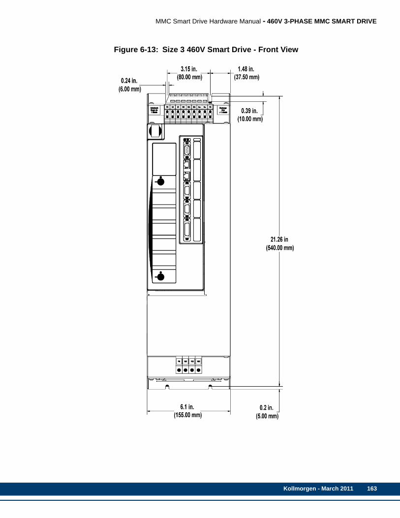
MMC Smart Drive Hardware Manual - 460V 3-PHASE MMC SMART DRIVE
Figure 6-13: Size 3 460V Smart Drive - Front View
Kollmorgen - March 2011 163
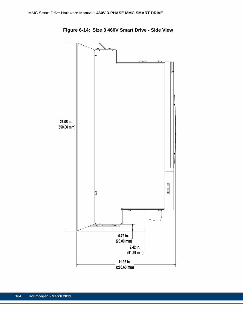
164
MMC Smart Drive Hardware Manual - 460V 3-PHASE MMC SMART DRIVE
Figure 6-14: Size 3 460V Smart Drive - Side View
Kollmorgen - March 2011
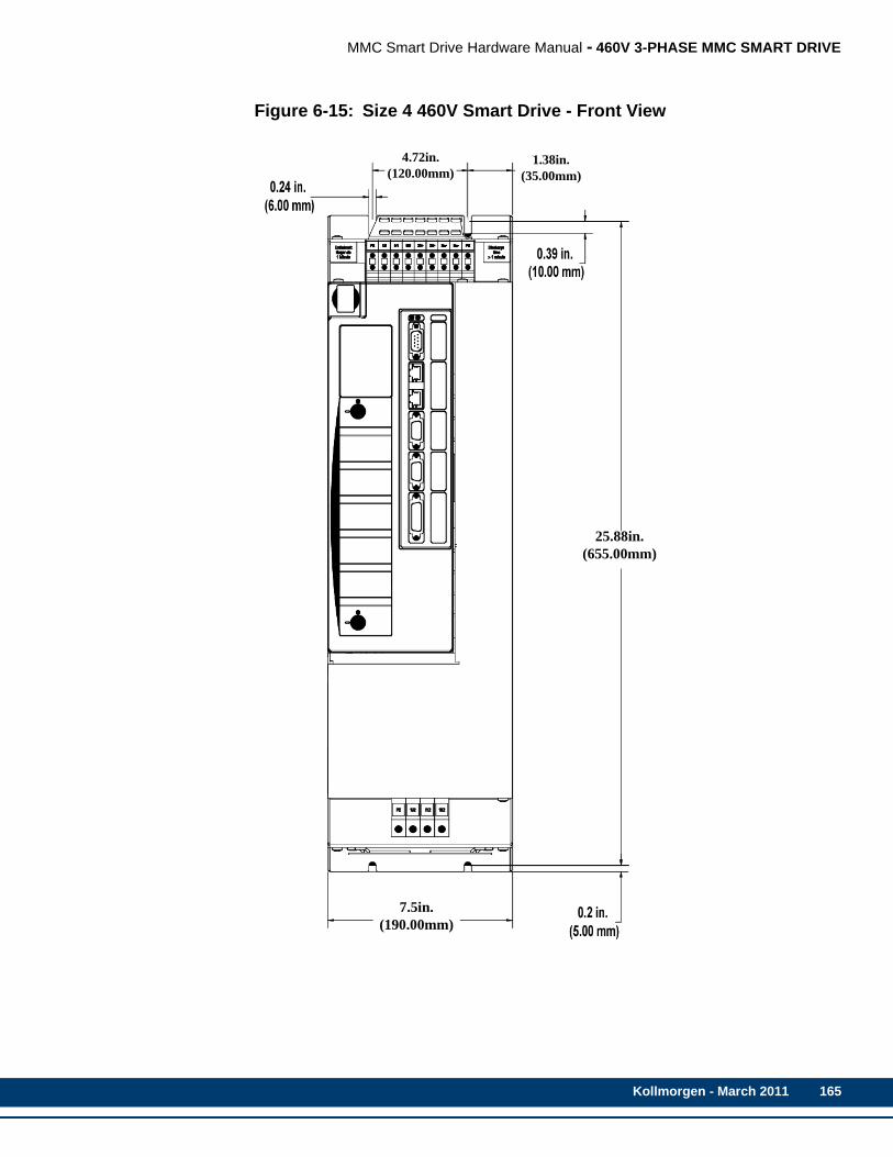
MMC Smart Drive Hardware Manual - 460V 3-PHASE MMC SMART DRIVE
Figure 6-15: Size 4 460V Smart Drive - Front View
7.5in.(190.00mm)
25.88in.(655.00mm)
4.72in.(120.00mm)
1.38in.(35.00mm)
Kollmorgen - March 2011 165
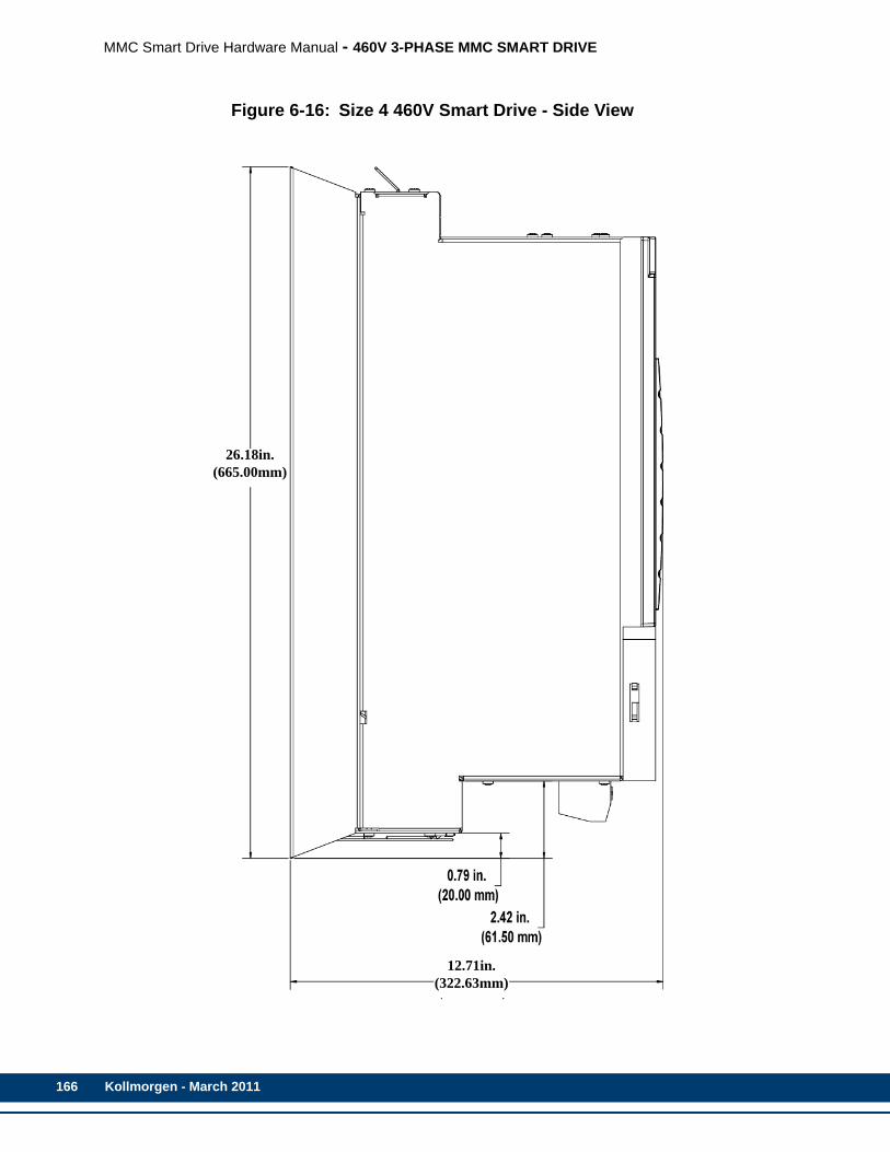
166
MMC Smart Drive Hardware Manual - 460V 3-PHASE MMC SMART DRIVE
Figure 6-16: Size 4 460V Smart Drive - Side View
26.18in.(665.00mm)
12.71in.(322.63mm)
Kollmorgen - March 2011

MMC Smart Drive Hardware Manual - S200-DLS DRIVE
7 S200-DLS DriveThis chapter only pertains to the S200-DLS Drive, not to the MMC Smart Drive.
The S200-DLS consists of a Base Unit with an S200 Digital Link Option Card installed. The combination of the two components is the S200-DLS Drive. The Base Unit is described in detail in Kollmorgen’s S200 Base Unit Reference Manual, P/N M-SM-200-01, which can be found at http://www.kollmorgen.com/website/com/eng/products/drives/ac_servo_drives/s200_manuals.php. Please refer to the S200 Base Unit Reference Manual for Base Unit Specifications, Mounting information, Wiring information, etc. The Base Unit has the same Part Number as the Digital Link version, except that the -DLS is replaced with -VTS. For example, a S20360-DLS consists of an S20360-VTS Base Unit and an S200 Digital Link Option Card.
Any data or specification contained in this manual takes precedence over conflicting data or specifications found in the Base Unit manual.
CE ENCLOSURE REQUIREMENTS
In order to meet the requirements of the CE Directives, the S200-DLSdrive(s) must be mounted within a grounded metal enclosure. Additional ac-tions may also be required, as described in the S200 Base Unit ReferenceManual, mentioned above.
BISS ENCODER SUPPORT
In order to use a BiSS encoder with the S200-DLS drive, the firmware withinthe drive must be Version 2.00 or later. In addition, the drive revision (asfound on the drive label), must be as follows:
•S20260-DLS - Rev 0 or higher•All others - Rev 3 or higher
Kollmorgen - March 2011 167
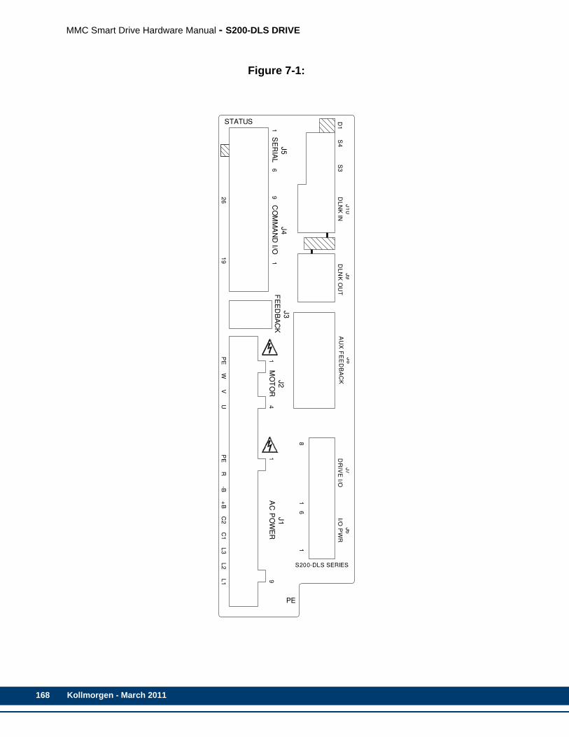
168
MMC Smart Drive Hardware Manual - S200-DLS DRIVE
Figure 7-1:
J4
CO
MM
AN
D I/O
J5
SE
RIA
L
STATUS
1
26
69
19 1
J3
FE
ED
BA
CK
J8
AU
X F
EE
DB
AC
K
S200-DLS SERIES
-BP
EW
UV
J2
MO
TO
R1
4
PE
R
1
L3
C2
+B
C1
J1
AC
PO
WE
R
L2
L1 9
PE
J1
0
DL
NK
IN
J9
DL
NK
OU
TS
4 S
3
J7
DR
IVE
I/O
J6
I/O P
WR
81
61
D1
Kollmorgen - March 2011
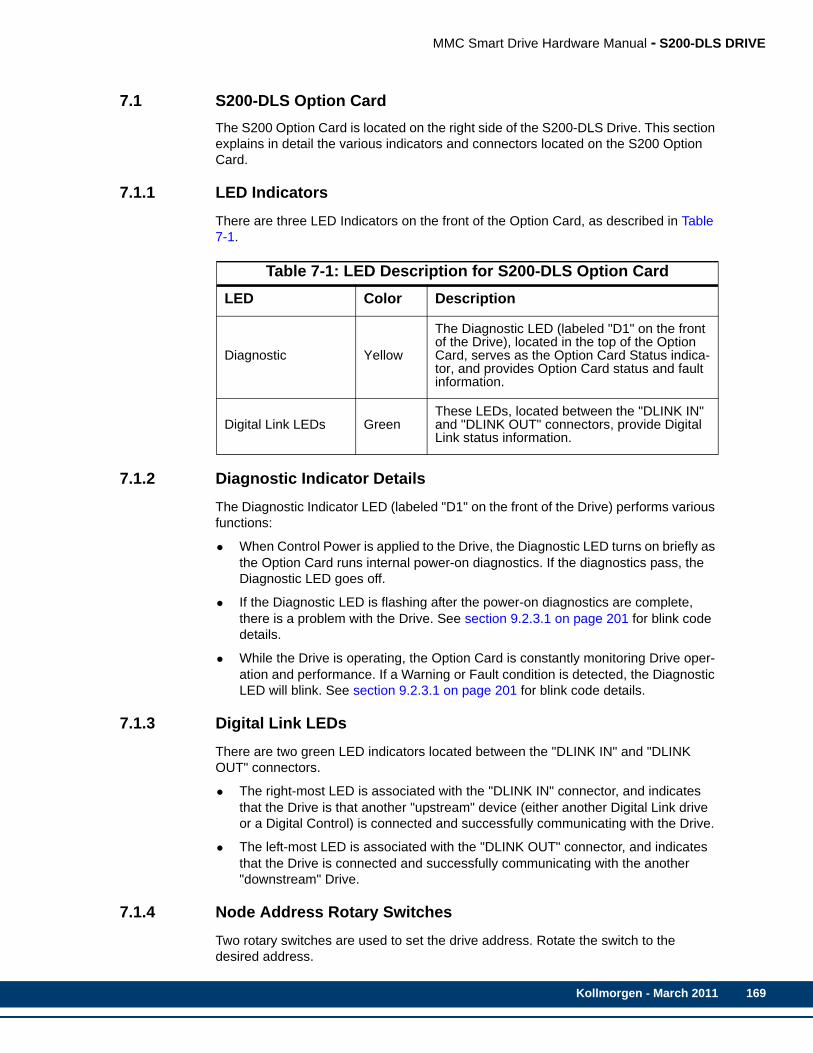
MMC Smart Drive Hardware Manual - S200-DLS DRIVE
7.1 S200-DLS Option CardThe S200 Option Card is located on the right side of the S200-DLS Drive. This section explains in detail the various indicators and connectors located on the S200 Option Card.
7.1.1 LED IndicatorsThere are three LED Indicators on the front of the Option Card, as described in Table 7-1.
7.1.2 Diagnostic Indicator DetailsThe Diagnostic Indicator LED (labeled "D1" on the front of the Drive) performs various functions:
• When Control Power is applied to the Drive, the Diagnostic LED turns on briefly as the Option Card runs internal power-on diagnostics. If the diagnostics pass, the Diagnostic LED goes off.
• If the Diagnostic LED is flashing after the power-on diagnostics are complete, there is a problem with the Drive. See section 9.2.3.1 on page 201 for blink code details.
• While the Drive is operating, the Option Card is constantly monitoring Drive oper-ation and performance. If a Warning or Fault condition is detected, the Diagnostic LED will blink. See section 9.2.3.1 on page 201 for blink code details.
7.1.3 Digital Link LEDsThere are two green LED indicators located between the "DLINK IN" and "DLINK OUT" connectors.
• The right-most LED is associated with the "DLINK IN" connector, and indicates that the Drive is that another "upstream" device (either another Digital Link drive or a Digital Control) is connected and successfully communicating with the Drive.
• The left-most LED is associated with the "DLINK OUT" connector, and indicates that the Drive is connected and successfully communicating with the another "downstream" Drive.
7.1.4 Node Address Rotary SwitchesTwo rotary switches are used to set the drive address. Rotate the switch to the desired address.
Table 7-1: LED Description for S200-DLS Option CardLED Color Description
Diagnostic Yellow
The Diagnostic LED (labeled "D1" on the front of the Drive), located in the top of the Option Card, serves as the Option Card Status indica-tor, and provides Option Card status and fault information.
Digital Link LEDs GreenThese LEDs, located between the "DLINK IN" and "DLINK OUT" connectors, provide Digital Link status information.
Kollmorgen - March 2011 169
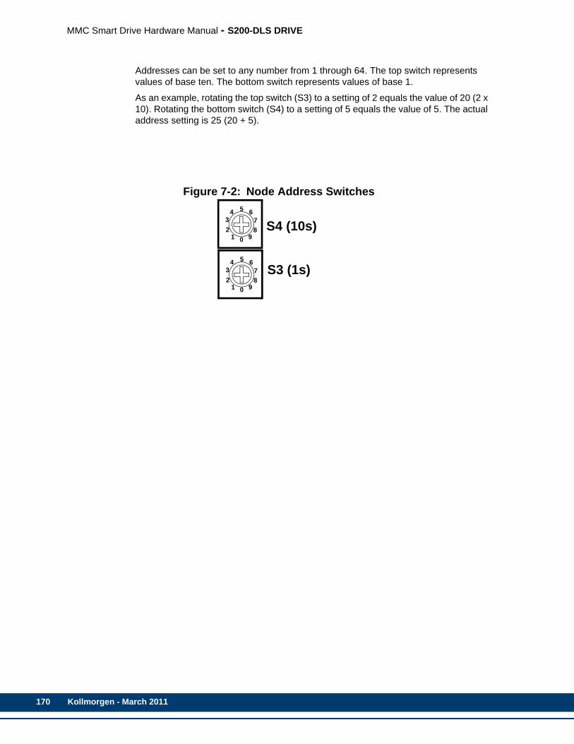
170
MMC Smart Drive Hardware Manual - S200-DLS DRIVE
Addresses can be set to any number from 1 through 64. The top switch represents values of base ten. The bottom switch represents values of base 1.
As an example, rotating the top switch (S3) to a setting of 2 equals the value of 20 (2 x 10). Rotating the bottom switch (S4) to a setting of 5 equals the value of 5. The actual address setting is 25 (20 + 5).
Figure 7-2: Node Address Switches
S4 (10s)
S3 (1s)0
5
1
432
678
9
0
5
1
432
678
9
Kollmorgen - March 2011

MMC Smart Drive Hardware Manual - S200-DLS DRIVE
7.1.5 Digital Link PortsThe two 8-pin RJ-45 Digital Link Port connectors (labeled “J10 DLINK IN” and “J9 DLINK OUT” on the front of the Drive) provide communications between the S200-DLS and:
• another S200-DLS Drive
• an MMC Smart Drive (including a Drive that contains a Drive Resident MMC Con-trol)
• an MMC-DSA Control (MMC-DSA2, -DSA4, -DSA8, -DSA16)
• a Digital Standalone MMC Control (MMC-D32, -D64)
Also provided are two green “Link” lights located between the RJ-45 connectors. The right light will be on if there is a Drive or Digital Control connected to the “IN” port, and the left light will be on if there is a Drive connected to the “OUT” port.
A “straight-through” shielded cable must be used when connecting to another device. Connect the cable from the Drive’s “DLINK OUT” port to the next Drives’s “DLINK IN” port, or from the MMC Digital Control’s Digital Link port to the Drive’s “DLINK IN” port. Refer to the Standalone MMC Hardware Manual for Standalone Digital Control information.
• Pin descriptions for are provided in Table 7-2
• Pin assignments are provided in Table 7-3
• The available Digital Link Port to Digital Drive cables are described in Table 7-4
Table 7-2: Digital Link Port Pin Description
Digital Link Connector (IN/OUT) Signals Pin
Function Notes“In”Connector
“Out” Connector
Receive Data+/- Receives data from connected drives. 1,2 3,6
Transmit Data +/- Transmits data to con-nected drives. 3,6 1,2
Protective Ground
Shield connection. Pro-vides a path for the ground signal to an ex-ternal single point ground.
Connector Shell Connector Shell
Kollmorgen - March 2011 171
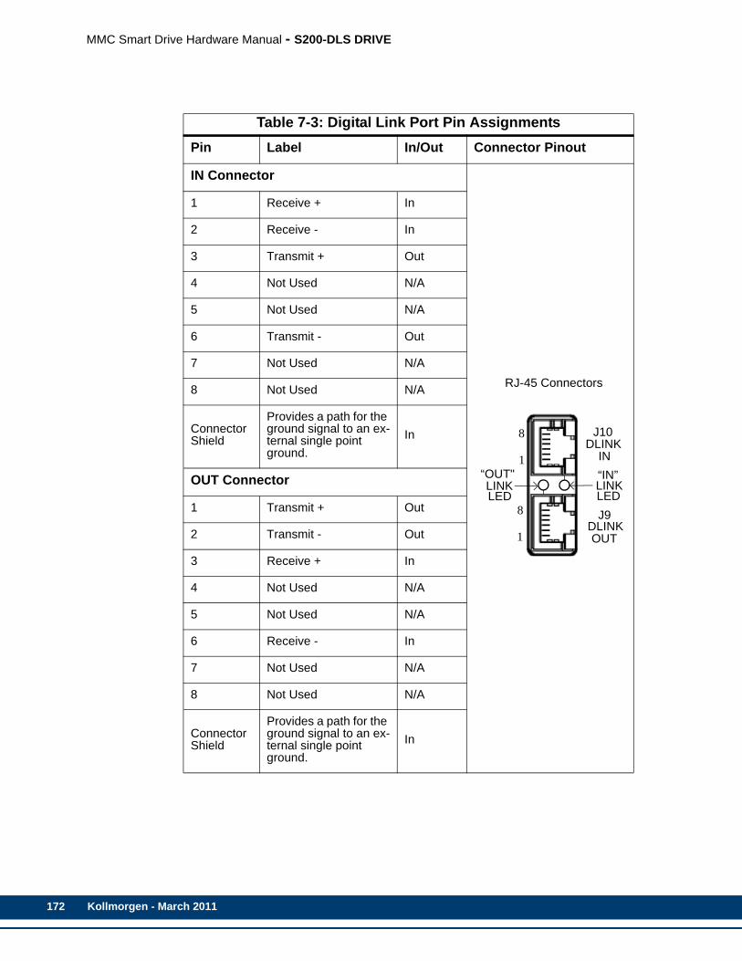
172
MMC Smart Drive Hardware Manual - S200-DLS DRIVE
Table 7-3: Digital Link Port Pin AssignmentsPin Label In/Out Connector Pinout
IN Connector
1 Receive + In
RJ-45 Connectors
2 Receive - In
3 Transmit + Out
4 Not Used N/A
5 Not Used N/A
6 Transmit - Out
7 Not Used N/A
8 Not Used N/A
Connector Shield
Provides a path for the ground signal to an ex-ternal single point ground.
In
OUT Connector
1 Transmit + Out
2 Transmit - Out
3 Receive + In
4 Not Used N/A
5 Not Used N/A
6 Receive - In
7 Not Used N/A
8 Not Used N/A
Connector Shield
Provides a path for the ground signal to an ex-ternal single point ground.
In
1
8
“OUT"LINK
“IN”LINKLEDLED
1
8DLINK IN
DLINK OUT
J10
J9
Kollmorgen - March 2011

MMC Smart Drive Hardware Manual - S200-DLS DRIVE
7.1.6 Auxiliary Feedback PortThe 15-pin female Auxiliary Feedback connector (labeled “J8 AUX FEEDBACK” on the front of the Drive) provides the interface between the S200-DLS Drive and a feedback device.
• Pin descriptions are provided in Table 7-5
• Pin assignments are provided in Table 7-6
• The available Flying Lead cable is described in Table 7-7.
• Available Breakout Boxes and Cables are described in Table 7-8.
• Breakout Box dimensions are shown in Figure 7-3
• Breakout Board dimensions are shown in Table 7-4
Table 7-4: Digital Link Port “IN” to “OUT” CablesPart Numbers:.3 M (1.0 ft): M.1302.8285 .6 M (2.0 ft): M.1302.82861 M (3.3 ft): M.1302.8287 2 M (6.6 ft): M.1302.82883 M (9.8 ft): M.1302.8289 5 M (16.4 ft): M.1302.830010 M (32.8 ft): M.1302.8301 15 M (49.2 ft): M.1302.830230 M (98.4 ft): M.1302.8303Cable type: CAT-5 (or better), 28 AWG, shielded, twisted pair, 8 conductor.
8-Pin RJ-45 Plug (to Digital Link Port “OUT”,
face view)
8-Pin RJ-45 Plug (to Digital Drive “IN”, face view)
Pin Signal Pin Signal Notes
1 Transmit Data + 1 Receive Data + Twisted
2 Transmit Data - 2 Receive Data - Pair
3 Receive Data + 3 Transmit Data + Twisted
6 Receive Data - 6 Transmit Data - Pair
4 None 4 None Twisted
5 None 5 None Pair
7 None 7 None Twisted
8 None 8 None Pair
Shell Drain Shell Drain
8
1 1
8
Kollmorgen - March 2011 173

174
MMC Smart Drive Hardware Manual - S200-DLS DRIVE
S
Ip
BC
MS
T
+p
Sm
Table 7-5: Aux Feedback Port Pin Description
Aux Feedback Signals
ignal Type Signal Name Notes Pin
ncremental Encoder In-uts A1, A1/, B1, B1/, I1, I1/ Differential A quad B encoder
signals. 1, 2, 3, 4, 5, 10
iSS Encoder Data hannel In/Outa
a. In order to use a BiSS encoder with the S200-DLS drive, the drive must be Rev 3 or later (as found on the drive label), and the firmware within the drive must be Version 2.03 or later.
RS-485 Data +, RS-485 Data -, RS-485 Clock+, RS-485 Clock-
RS-485 signals for connecting a BiSS Encoder Data Channel to the drive
5, 10, 12, 13
otor Commutation Hall ensor Inputs
Commutation Track S1, S2, S3
Hall device input signals that are used to initialize the com-mutation angle. They consist of a 74HC14 input with 10μs filter and 1 K pull up to +5V. Shared with F2.
12, 13, 8
emperature Input Temperature
Thermostat (normally- closed) or Thermistor (Phillips KTY84-130 PTC or equivalent recom-mended) input for detecting over temperature conditions within the motor.
11
5V Encoder Power Out-uts +5V Source
Regulated +5VDC for powering the attached encoder (250ma max).
14
ignal and Power Com-on Common Return path for feedback sig-
nals and +5V power supply. 6
Kollmorgen - March 2011
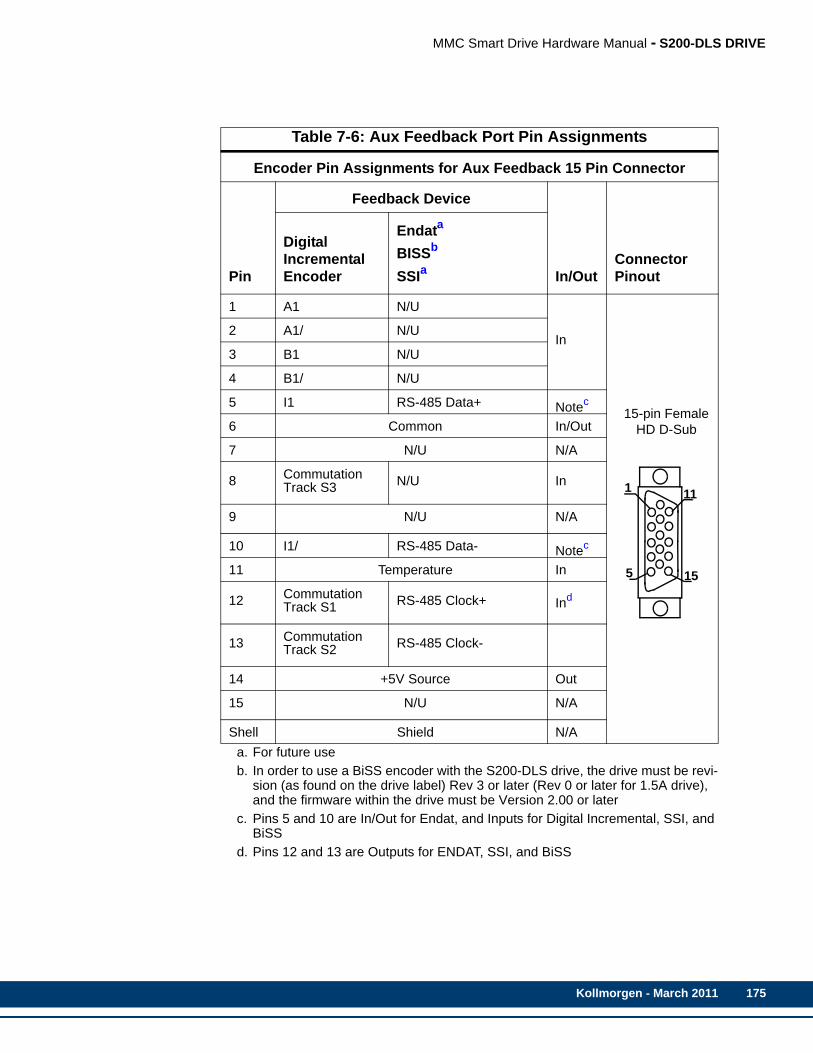
MMC Smart Drive Hardware Manual - S200-DLS DRIVE
Table 7-6: Aux Feedback Port Pin Assignments
Encoder Pin Assignments for Aux Feedback 15 Pin Connector
Pin
Feedback Device
In/OutConnector Pinout
Digital Incremental Encoder
Endata
BISSb
SSIa
a. For future useb. In order to use a BiSS encoder with the S200-DLS drive, the drive must be revi-
sion (as found on the drive label) Rev 3 or later (Rev 0 or later for 1.5A drive), and the firmware within the drive must be Version 2.00 or later
1 A1 N/U
In
15-pin FemaleHD D-Sub
2 A1/ N/U
3 B1 N/U
4 B1/ N/U
5 I1 RS-485 Data+ Notec
c. Pins 5 and 10 are In/Out for Endat, and Inputs for Digital Incremental, SSI, and BiSS
6 Common In/Out
7 N/U N/A
8 CommutationTrack S3 N/U In
9 N/U N/A
10 I1/ RS-485 Data- Notec
11 Temperature In
12 CommutationTrack S1 RS-485 Clock+ Ind
d. Pins 12 and 13 are Outputs for ENDAT, SSI, and BiSS
13 CommutationTrack S2 RS-485 Clock-
14 +5V Source Out
15 N/U N/A
Shell Shield N/A
5
1
15
11
Kollmorgen - March 2011 175

176
MMC Smart Drive Hardware Manual - S200-DLS DRIVE
Table 7-7: Aux Feedback Port to Flying Lead CablePart Numbers: 1 M (3.3 ft): M.3000.0805 3 M (9.8 ft): M.3000.0806 6 M (19.7 ft): M.3000.0807 9 M (19.5 ft): M.3000.0808Cable type: 28 AWG (pins 6 & 14 16 AWG), shielded, twisted pair, 16 conductor.
15-Pin HD male D-sub (to Aux Feedback Port, face view)
Pin Signal Color Notes
1 A1 White Twisted
2 A1/ White/Yellow Pair
3 B1 Blue Twisted
4 B1/ White/Blue Pair
5 I1, RS-485 Data+ Black Twisted
10 I1/, RS-485 Data- White/Black Pair
8 Commutation Track S3 Red Twisted
Not Connected White/Red Pair
14 +5V source Gray Twisted
6 Common White/Gray Pair
11 Temperature Green Twisted
Not Connected White/Green Pair
12 Commutation Track S1, RS-485 Clock+ Violet Twisted
13 Commutation Track S2, RS-485 Clock- White/Violet Pair
Not Connected Orange Twisted
Not Connected White/Orange Pair
7 Not Used Brown Twisted
Not Connected White/Brown Pair
Shell Drain N/A
5
1
15
11
Kollmorgen - March 2011
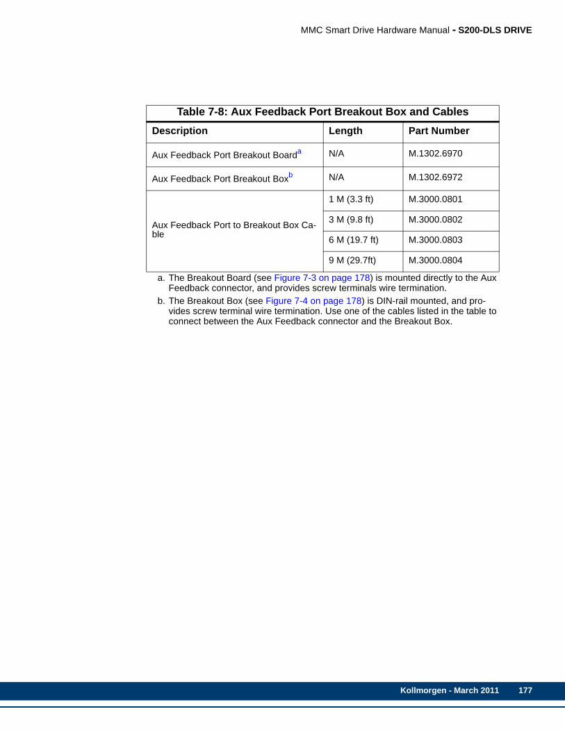
MMC Smart Drive Hardware Manual - S200-DLS DRIVE
Table 7-8: Aux Feedback Port Breakout Box and CablesDescription Length Part Number
Aux Feedback Port Breakout Boarda
a. The Breakout Board (see Figure 7-3 on page 178) is mounted directly to the Aux Feedback connector, and provides screw terminals wire termination.
N/A M.1302.6970
Aux Feedback Port Breakout Boxb
b. The Breakout Box (see Figure 7-4 on page 178) is DIN-rail mounted, and pro-vides screw terminal wire termination. Use one of the cables listed in the table to connect between the Aux Feedback connector and the Breakout Box.
N/A M.1302.6972
Aux Feedback Port to Breakout Box Ca-ble
1 M (3.3 ft) M.3000.0801
3 M (9.8 ft) M.3000.0802
6 M (19.7 ft) M.3000.0803
9 M (29.7ft) M.3000.0804
Kollmorgen - March 2011 177

178
MMC Smart Drive Hardware Manual - S200-DLS DRIVE
Figure 7-3: Aux Feedback Port Breakout Box Dimensions
Figure 7-4: Aux Feedback Port Breakout Board Dimensions
Kollmorgen - March 2011

MMC Smart Drive Hardware Manual - S200-DLS DRIVE
Table 7-9: Aux Feedback Port ENDAT/BiSS to AKM/DDR Motor CablePart Numbers:1 M (3.3 ft): M.1302.0809 3 M (9.8 ft): M.1302.0810 6 M (19.7 ft): M.1302.08119 M (29.5 ft): M.1302.0812 15 M (49.2 ft): M.1302.0813 30 M (98.4 ft): M.1302.0814
Twisted Pair7 pair 26
AWG1 pair 16
AWG1 pair 22
AWG
15-Pin HD male D-sub Connector to MMC Smart
Drive Connector to Motor
Wire Color
Pin Number
Signal Type
Pin Number
Jumper Connections Signal Type
Yellow 1 COS 9 B+
White/Yellow 2 COS/ 1 B-
Blue 3 SIN 11 A+
White/Blue 4 SIN/ 3 A-
Black 5 DATA+ 5 DATA
White/Black 10 DATA- 13 DATA/
Violet 12 CLOCK+ 8 CLOCK
White/Violet 13 CLOCK- 15 CLOCK/
Red N/U N/A 12 UnSENSE VCC
White/Red N/U N/A 10 UnSENSE COM
Green 11 TEMPERATUR 7 THERMAL
White/Green N/U N/A 14 THERMAL
Orange N/U N/A N/U N/A
White/Orange N/U N/A N/U N/A
Brown 7 9 VDC N/U N/A
White/Brown N/U N/A N/U N/A
Gray 14 +5 VDC 4 5VDC
White/Gray 6 COM 2 GMD
N/C 9 N/A 6 N/C
N/C 15 N/A 16 N/C
N/C 8 N/A 17 N/C
5
1
15
11 12
3
45 6
7
8
9
1011
1213
14 15
1617
Kollmorgen - March 2011 179
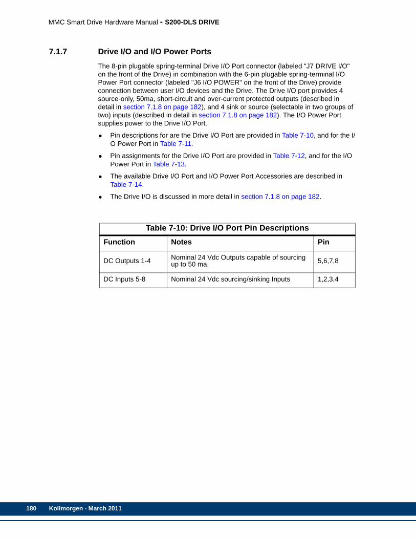
180
MMC Smart Drive Hardware Manual - S200-DLS DRIVE
7.1.7 Drive I/O and I/O Power PortsThe 8-pin plugable spring-terminal Drive I/O Port connector (labeled "J7 DRIVE I/O" on the front of the Drive) in combination with the 6-pin plugable spring-terminal I/O Power Port connector (labeled "J6 I/O POWER" on the front of the Drive) provide connection between user I/O devices and the Drive. The Drive I/O port provides 4 source-only, 50ma, short-circuit and over-current protected outputs (described in detail in section 7.1.8 on page 182), and 4 sink or source (selectable in two groups of two) inputs (described in detail in section 7.1.8 on page 182). The I/O Power Port supplies power to the Drive I/O Port.
• Pin descriptions for are the Drive I/O Port are provided in Table 7-10, and for the I/O Power Port in Table 7-11.
• Pin assignments for the Drive I/O Port are provided in Table 7-12, and for the I/O Power Port in Table 7-13.
• The available Drive I/O Port and I/O Power Port Accessories are described in Table 7-14.
• The Drive I/O is discussed in more detail in section 7.1.8 on page 182.
Table 7-10: Drive I/O Port Pin DescriptionsFunction Notes Pin
DC Outputs 1-4 Nominal 24 Vdc Outputs capable of sourcing up to 50 ma. 5,6,7,8
DC Inputs 5-8 Nominal 24 Vdc sourcing/sinking Inputs 1,2,3,4
Kollmorgen - March 2011

MMC Smart Drive Hardware Manual - S200-DLS DRIVE
Table 7-11: Drive I/O Port Pin AssignmentsPin Signal In/Out Connector Pinout
1 DC Input 8 In
8-Pin plugable Screw Terminal Connector
2
DC Input 7(Data Capture input for J8 Aux Feedback connector)
In
3 DC Input 6 In
4
DC Input 5(Data Capture input for J3 SFD Feedback connector)
In
5 DC Output 4 Out
6 DC Output 3 Out
7 DC Output 2 Out
8 DC Output 1 Out
8
1
J7DRIVE
I/O
Kollmorgen - March 2011 181
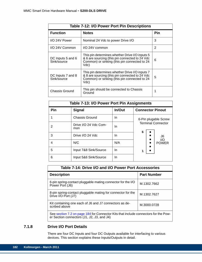
182
MMC Smart Drive Hardware Manual - S200-DLS DRIVE
7.1.8 Drive I/O Port DetailsThere are four DC Inputs and four DC Outputs available for interfacing to various devices. This section explains these Inputs/Outputs in detail.
Table 7-12: I/O Power Port Pin DescriptionsFunction Notes Pin
I/O 24V Power Nominal 24 Vdc to power Drive I/O 3
I/O 24V Common I/O 24V common 2
DC Inputs 5 and 6 Sink/source
This pin determines whether Drive I/O inputs 5 & 6 are sourcing (this pin connected to 24 Vdc Common) or sinking (this pin connected to 24 Vdc)
6
DC Inputs 7 and 8 Sink/source
This pin determines whether Drive I/O inputs 7 & 8 are sourcing (this pin connected to 24 Vdc Common) or sinking (this pin connected to 24 Vdc)
5
Chassis Ground This pin should be connected to Chassis Ground 1
Table 7-13: I/O Power Port Pin AssignmentsPin Signal In/Out Connector Pinout
1 Chassis Ground In 6-Pin plugable Screw Terminal Connector
2 Drive I/O 24 Vdc Com-mon In
3 Drive I/O 24 Vdc In
4 N/C N/A
5 Input 7&8 Sink/Source In
6 Input 5&6 Sink/Source In
Table 7-14: Drive I/O and I/O Power Port AccessoriesDescription Part Number
6-pin spring-contact pluggable mating connector for the I/O Power Port (J6) M.1302.7662
8-pin spring-contact pluggable mating for connector for the Drive I/O Port (J7) M.1302.7627
Kit containing one each of J6 and J7 connectors as de-scribed above M.3000.0728
See section 7.2 on page 184 for Connector Kits that include connectors for the Pow-er Section connectors (J1, J2, J3, and J4)
6
1
J6
POWERI/O
Kollmorgen - March 2011

MMC Smart Drive Hardware Manual - S200-DLS DRIVE
7.1.8.1 Drive I/O Port OutputsThe Drive I/O Port provides 4 source-only 24 Vdc outputs. For sourcing outputs, one side of the load is connected to the Output pin on the Drive I/O connector, and the other side of the load is connected to 24 Vdc Common.
These outputs get their power from Pin 3 of the I/O Power connector. Each of the 4 outputs on the Drive I/O connector is a solid state switch rated at 50 ma, and is short-circuit and over-current protected. In addition, each output is protected with internal clamping diodes. Without clamping, high voltage transients (kickback) from inductive loads might damage the module. For safety reasons, all outputs turn off (no current flow) when a the user program (Ladder) is not running (Scan Loss), or communications to the Drive is lost.
7.1.8.2 Drive I/O Port InputsThe Drive I/O Port also provides 4 sink/source 24 Vdc inputs.
To configure an Input as Sinking, the Sink/Source select pin (pin 6 for Inputs 5 and 6, pin 5 for inputs 7 and 8), must be connected to 24 Vdc. When configured as Sinking, one side of the input device is connected to the Input pin on the Drive I/O Port connector, and the other side of the input device must be connected to 24 Vdc Common.
To configure an Input as Sourcing, the Sink/Source select pin (pin 6 for Inputs 5 and 6, pin 5 for inputs 7 and 8), must be connected to 24 Vdc Common. When configured as Sourcing, one side of the input device is connected to the Input pin on the Drive I/O Port connector, and the other side of the input device must be connected to 24 Vdc.
7.1.8.3 Drive I/O Port Wiring ExampleAn example of wiring the Drive I/O is shown in See Figure 7-5 on page 184.
• Since the Outputs are sourcing, one side of the output device is connected to the Output pin on the Drive I/O Port connector, and the other side is connected to 24 Vdc Common.
• The Sink/Source select pin for Inputs 5 and 6 on the I/O Power Port connector is connected to 24 Vdc, making Drive Inputs 5 and 6 Sinking. In this configuration, one side of the input device is connected to the Input pin on the Drive I/O Port connector, and the other side of the input device is connected to 24 Vdc Common.
• The Sink/Source select pin for inputs 7 and 8 on the I/O Power Port connector is connected to 24 Vdc Common, making Drive Inputs 7 and 8 Sourcing. In this con-figuration, one side of the input device is connected to the Input pin on the Drive I/O Port connector, and the other side of the input device is connected to 24 Vdc.
Kollmorgen - March 2011 183

184
MMC Smart Drive Hardware Manual - S200-DLS DRIVE
Figure 7-5: Connecting Devices to the Drive I/O Port
7.2 Power Section Wiring AccessoriesThis section describes wiring accessories related to the Power Section of the S200-DLS Drives.
To
Drive I/O Port
24 Vdc Power Supply+ _
SPG
5&6 SS
LOADS
5
1
4
3
2
5
6
7
8
4
DCOUT1
DCOUT2
DCOUT3
DCOUT4
7&8 SS
24VDCIN
2
3
24VDC COM
DCIN5
DCIN6
DCIN7
DCIN8 1
6
CHASSIS
J7DRIVE I/O
J6I/O PWR
SINKING
SOURCING
Kollmorgen - March 2011

MMC Smart Drive Hardware Manual - S200-DLS DRIVE
Table 7-15: Power Section Wiring AccessoriesDescription Part Number
Command I/O (J4) Drive-mounted Breakout Board M.1302.6971
Command I/O (J4) Panel-mounted Breakout Box M.1302.6973
Command I/O (J4) to Breakout Box cables:3.3ft (1M)9.8ft (3M)29.5ft (9M)
M.1302.6982M.1302.6984M.1302.6985
AC Power (J1, 1.5A, 3A, and 6A S200-DLS drives only)9-pin screw terminal 767-009903-01
Ctrl Power (J1, 12A and 24A S200-DLS drives only)3-pin screw terminal 767-003907-01
Motor Power (J2, 1.5A, 3A, and 6A S200-DLS drives onlya)4-pin screw terminal
a. J2 is not present on the 12A and 24A S200-DLS drives. Connection for Motor Power is provided via a non-pluggable screw-terminal connector.
767-004908-01
Feedback (J3)6-pin, solder terminal 749-139401-01
Kit containing one each of connector J1 (P/N 767-003907-01, as described above), plus J6 and J7 (as described in Table 7-14 on page 182)
M.3000.0727
Kit containing one each of connector J1 (P/N 767-009903-01, as described above), plus J6 and J7 (as described in Table 7-14 on page 182)
M.3000.0728
Kollmorgen - March 2011 185
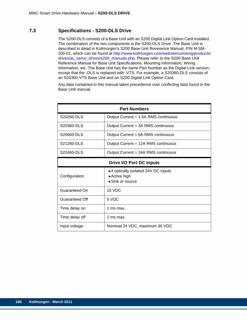
186
MMC Smart Drive Hardware Manual - S200-DLS DRIVE
7.3 Specifications - S200-DLS DriveThe S200-DLS consists of a Base Unit with an S200 Digital Link Option Card installed. The combination of the two components is the S200-DLS Drive. The Base Unit is described in detail in Kollmorgen’s S200 Base Unit Reverence Manual, P/N M-SM-200-01, which can be found at http://www.kollmorgen.com/website/com/eng/products/drives/ac_servo_drives/s200_manuals.php. Please refer to the S200 Base Unit Reference Manual for Base Unit Specifications, Mounting information, Wiring information, etc. The Base Unit has the same Part Number as the Digital Link version, except that the -DLS is replaced with -VTS. For example, a S20360-DLS consists of an S20360-VTS Base Unit and an S200 Digital Link Option Card.
Any data contained in this manual takes precedence over conflicting data found in the Base Unit manual.
Part Numbers
S20260-DLS Output Current = 1.5A RMS continuous
S20360-DLS Output Current = 3A RMS continuous
S20660-DLS Output Current = 6A RMS continuous
S21260-DLS Output Current = 12A RMS continuous
S22460-DLS Output Current = 24A RMS continuous
Drive I/O Port DC Inputs
Configuration•4 optically isolated 24V DC inputs•Active high•Sink or source
Guaranteed On 15 VDC
Guaranteed Off 5 VDC
Time delay on 1 ms max.
Time delay off 1 ms max.
Input voltage Nominal 24 VDC, maximum 30 VDC
Kollmorgen - March 2011

MMC Smart Drive Hardware Manual - S200-DLS DRIVE
Drive I/O Port DC Outputs
Configuration
•4 optically isolated 24V DC outputs•Active high•Current sourcing only (current into load)•Short circuit and overload protected
Maximum current 50mA per output
Voltage range 24VDC +15%-10%
Time delay on for resis-tive loads 50 µsec. max
Time delay off for resis-tive loads 50 µsec. max
Leakage current in off state 0.5 mA max
Digital Link In/Out Ports
“In” port Sends and receives high speed data to and from connect-ed MMC-SD’s “Out” port.
“Out” port Sends and receives high speed data to and from connect-ed MMC-SD’s “In” port.
Cable Type Shielded, Straight Pinned, CAT5 or better (CAT5e, CAT6, etc.)
Maximum Cable Length 30 m (98.4 ft)
Conformity
CE Marked
Note: Only units Rev 1 or higher are CE Marked.
Conforms to Low Voltage Directive 73/23/EEC (amended by 93/68/EEC) and EMC Directive 89/336/EEC (amended by 92/31/EEC and 93/68/EEC).Conformance is in accordance with the following stan-dards:EN 50178 and EN61800-3
UL and C/UL Recog-nized E233454
RoHs The S200-DLS Drives are not RoHs compliant
Kollmorgen - March 2011 187

188
MMC Smart Drive Hardware Manual - S200-DLS DRIVE
Kollmorgen - March 2011
MMC Smart Drive Hardware Manual - MOTOR CABLES & CONNECTORS
8 Motor Cables & ConnectorsKollmorgen offers many cables that connect directly from the MMC Smart Drive’s F1/F2 connector to various Kollmorgen motors. These cables are described in detail in section 5.1.6.2 on page 86.
This section describes additional cables and connector kits that can be used to connect Kollmorgen motors and drives, as well as providing cable installation guidelines.
8.1 Flex Cable Installation GuidelinesFollow these guidelines for any flexing cable application:
• Cable should be hung suspended for 48 hours to develop its most natural “set* and lay” prior to installation
• A cable should be installed with, not against, its natural set
• Using strain relief fittings at both ends of the cable will reduce conductor breakage at the flex points
• If there is any kink in a cable after installation, it will always remain and eventually cause a cable failure
• After installation, the most critical factors in the cable are the minimum bend radius and the reel tension
* Note: The natural set occurs during the manufacturing of the cable. The cable is cured in one direction on the reel with a notable difference in its ability to be flexed one way versus the other.
When using specially designed flex cables, the following five criteria must be considered:
• Bending Radius
• Cable Tension
• Operating Speed
• Temperature
• Ampacity
Bending Radius and Cable Tension are discussed in the following sections.
8.1.1 Bending RadiusThe following guidelines recommended by the ICEA standards are intended to optimize cable life:
• Minimum Bend Radius (Shielded Feedback Cables) = 12 times the Cable Diame-ter
• Minimum Bend Radius (Shielded Power Cables) = 12 times the Cable Diameter
Reduced bending radii result in reduced cable life due to increased stress on the copper conductors and overall distortion of the cable. Therefore, reduced radii should only be considered for applications in which other factors, such as reduced cable tension, lower operating speed, and ambient temperature are more favorable to cable life, or where the mechanical limitations of the installation do not allow the optimum radius.
Kollmorgen - March 2011 189

190
MMC Smart Drive Hardware Manual - MOTOR CABLES & CONNECTORS
Doubling the minimum bending radius for reeling applications can triple cable life at the maximum recommended tension. Therefore, the largest possible bending radius should be used to increase cable life.
8.1.2 Cable TensionCable tension plays an extremely important role in determining cable life in reeling. The copper conductors are the principle strength member in flexible cable constructions. Even if strain relief fittings are used on the cable ends, most of the tension will still be supported by the copper conductors.
The effects of tension on a cable are dependent upon the pounds per cross-sectional area of the copper conductors. Larger AWG wires and/or more conductors can handle more tension than smaller AWG wires and/or fewer conductors.
8.2 Flex Cable InstallationCables should be fixed on both ends to relieve them of tensile loads and prevent any loads from being applied to the molded connectors. At a minimum, the cables have to be fixed on the moving end of the track. A distance of 3 to 6 inches from the track to the fixation point is recommended (See Figure 8-1).
Figure 8-1: Flex Cable Installation
Observe the following precautions when installing flex cables:
WARNING: CABLE DAMAGE
Failure to properly isolate Flex, Pull, and Torsional forces from the connectorends will result in electrical and mechanical breakdown. Over clamping at thefixation point can result in cable damage.
Kollmorgen - March 2011

MMC Smart Drive Hardware Manual - MOTOR CABLES & CONNECTORS
• The cable must be able to move freely in the track
• The cable must be able to move in the radius section of the track. This must be checked in the track’s fully extended position.
• When cables of different diameters are installed, the use of vertical separators or horizontal shelving is recommended. Cables of similar diameters can be put in the same compartment.
• Cables should never be put on top of one another in high velocity or high cycle applications.
• The cable’s weight should be distributed symmetrically over the chain width.
Kollmorgen - March 2011 191
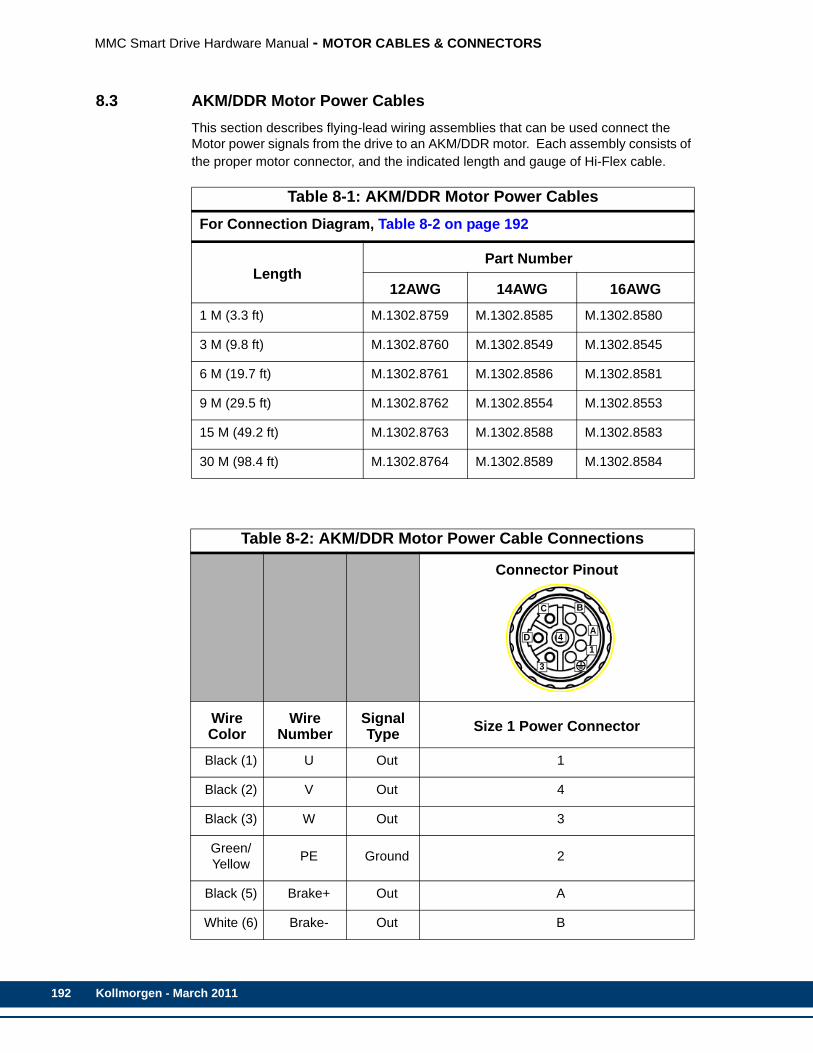
192
MMC Smart Drive Hardware Manual - MOTOR CABLES & CONNECTORS
8.3 AKM/DDR Motor Power CablesThis section describes flying-lead wiring assemblies that can be used connect the Motor power signals from the drive to an AKM/DDR motor. Each assembly consists of the proper motor connector, and the indicated length and gauge of Hi-Flex cable.
Table 8-1: AKM/DDR Motor Power CablesFor Connection Diagram, Table 8-2 on page 192
LengthPart Number
12AWG 14AWG 16AWG
1 M (3.3 ft) M.1302.8759 M.1302.8585 M.1302.8580
3 M (9.8 ft) M.1302.8760 M.1302.8549 M.1302.8545
6 M (19.7 ft) M.1302.8761 M.1302.8586 M.1302.8581
9 M (29.5 ft) M.1302.8762 M.1302.8554 M.1302.8553
15 M (49.2 ft) M.1302.8763 M.1302.8588 M.1302.8583
30 M (98.4 ft) M.1302.8764 M.1302.8589 M.1302.8584
Table 8-2: AKM/DDR Motor Power Cable Connections
Connector Pinout
Wire Color
Wire Number
Signal Type Size 1 Power Connector
Black (1) U Out 1
Black (2) V Out 4
Black (3) W Out 3
Green/Yellow PE Ground 2
Black (5) Brake+ Out A
White (6) Brake- Out B
B
A
C
D
3
14
Kollmorgen - March 2011

MMC Smart Drive Hardware Manual - MOTOR CABLES & CONNECTORS
8.4 LSM/MSM Motor Connector Kits This section describes LSM/MSM Motor mating connectors for use in constructing custom cables using user-supplied cable. Available connectors are described in Table 8-3.
Table 8-3: Connector Kits for LSM/MSM MotorsFunction Wire Size Part Number Figure
Feedback 18-28AWG M.1302.0500
Feedback 18-28AWG M.1302.0510
Power/Brake 14-16AWG M.1302.0479
Power/Brake 12AWG M.1302.8755
Power/Brake 12-14AWG M.1302.1998
Power/Brake 8-10AWG M.1302.2354
Power/Brake 6AWG M.1302.7492Consult Factory
Power/Brake 4AWG M.1302.7493
Fan 16AWG M.1302.6219
12
3
45 6
7
8
9
1011
1213
14 15
1617
B
A
C
D
3
14
+ V
U
1 2
W
1 2
4
3
5
6
Kollmorgen - March 2011 193
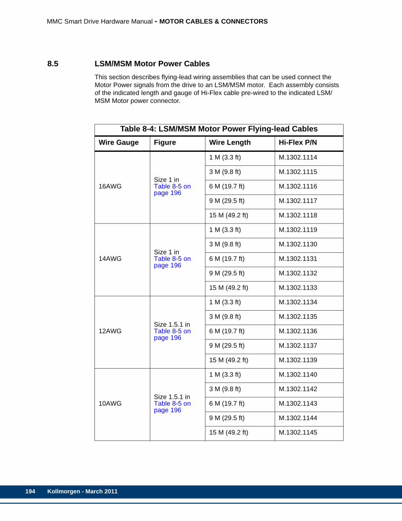
194
MMC Smart Drive Hardware Manual - MOTOR CABLES & CONNECTORS
8.5 LSM/MSM Motor Power CablesThis section describes flying-lead wiring assemblies that can be used connect the Motor Power signals from the drive to an LSM/MSM motor. Each assembly consists of the indicated length and gauge of Hi-Flex cable pre-wired to the indicated LSM/MSM Motor power connector.
Table 8-4: LSM/MSM Motor Power Flying-lead CablesWire Gauge Figure Wire Length Hi-Flex P/N
16AWGSize 1 in Table 8-5 on page 196
1 M (3.3 ft) M.1302.1114
3 M (9.8 ft) M.1302.1115
6 M (19.7 ft) M.1302.1116
9 M (29.5 ft) M.1302.1117
15 M (49.2 ft) M.1302.1118
14AWGSize 1 in Table 8-5 on page 196
1 M (3.3 ft) M.1302.1119
3 M (9.8 ft) M.1302.1130
6 M (19.7 ft) M.1302.1131
9 M (29.5 ft) M.1302.1132
15 M (49.2 ft) M.1302.1133
12AWGSize 1.5.1 in Table 8-5 on page 196
1 M (3.3 ft) M.1302.1134
3 M (9.8 ft) M.1302.1135
6 M (19.7 ft) M.1302.1136
9 M (29.5 ft) M.1302.1137
15 M (49.2 ft) M.1302.1139
10AWGSize 1.5.1 in Table 8-5 on page 196
1 M (3.3 ft) M.1302.1140
3 M (9.8 ft) M.1302.1142
6 M (19.7 ft) M.1302.1143
9 M (29.5 ft) M.1302.1144
15 M (49.2 ft) M.1302.1145
Kollmorgen - March 2011

MMC Smart Drive Hardware Manual - MOTOR CABLES & CONNECTORS
8AWGSize 1.5.2 in Table 8-5 on page 196
1 M (3.3 ft) M.1302.1146
3 M (9.8 ft) M.1302.1147
6 M (19.7 ft) M.1302.1148
9 M (29.5 ft) M.1302.1149
15 M (49.2 ft) M.1302.1150
6AWG Consult Factory
1 M (3.3 ft) M.3000.tbd
3 M (9.8 ft) M.3000.tbd
6 M (19.7 ft) M.3000.tbd
9 M (29.5 ft) M.3000.tbd
15 M (49.2 ft) M.3000.tbd
4AWG Consult Factory
1 M (3.3 ft) M.3000.tbd
3 M (9.8 ft) M.3000.tbd
6 M (19.7 ft) M.3000.tbd
9 M (29.5 ft) M.3000.tbd
15 M (49.2 ft) M.3000.tbd
2AWG Consult Factory
1 M (3.3 ft) M.3000.tbd
3 M (9.8 ft) M.3000.tbd
6 M (19.7 ft) M.3000.tbd
9 M (29.5 ft) M.3000.tbd
15 M (49.2 ft) M.3000.tbd
Kollmorgen - March 2011 195

196
MMC Smart Drive Hardware Manual - MOTOR CABLES & CONNECTORS
Table 8-5: LSM/MSM Motor Power Connector Flying Lead Cables
Connector Pinout
Wire Color
Wire Number
Signal Type
Size 1 Power Connector
Size 1.5.1 Power
Connector
Size 1.5.2 Power
Connector
Black (1) 1U2 Out 1 U
Black (2) 1V2 Out 3 V
Black (3) 1W2 Out 4 W
Green/Yellow
PE Ground 2
Black (5) Brake+ Out A +
Black (6) Brake- Out B -
B
A
C
D
3
14
+ V
U
1 2
W
Kollmorgen - March 2011

MMC Smart Drive Hardware Manual - MOTOR CABLES & CONNECTORS
8.6 LSM/MSM Motor Fan CablesThis section describes flying-lead wiring assemblies that can be used connect the Motor Fan signals from the drive to an LSM/MSM motor. Each assembly consists of the indicated length of 16AWG cable pre-wired to the LSM/MSM Motor fan connector. The wiring Diagram for these cables can be found in Table 8-7.Table 8-6: LSM/MSM Motor Fan CablesCable Length Part Number
1 M (3.3 ft) M.1302.6310
3 M (9.8 ft) M.1302.6311
6 M (19.7 ft) M.1302.6312
9 M (29.5 ft) M.1302.6313
15 M (49.2 ft) M.1302.6314
Table 8-7: LSM/MSM Fan Motor Flying Lead Cable
Connector Pinout
Wire Color Wire Number
Signal Type Pin
Brown U Out 1
Black N Out 2
Green/Yellow PE Ground 3
1 2
4
3
5
6
Kollmorgen - March 2011 197

198
MMC Smart Drive Hardware Manual - MOTOR CABLES & CONNECTORS
Kollmorgen - March 2011

MMC Smart Drive Hardware Manual - MAINTENANCE AND TROUBLESHOOTING
9 Maintenance and Troubleshooting9.1 Maintenance
• Remove superficial dust and dirt from the drive.
• Check cable insulation and connections.
• Clean exterior surfaces and airflow vents using an OSHA approved nozzle that provides compressed air under low pressure of less than 20 kPa (30 psi).
• Visually check for cable damage. Replace all damaged cables.
• Inspect D-shell connectors for proper seating and signal continuity end-to-end.
WARNING
Disconnect input power before touching cables orconnections.DC bus capacitors may retain hazardous voltages af-ter input power has been removed.Before working on the drive, measure the DC busvoltage to verify it has reached a safe level.Failure to observe this precaution could result in se-vere bodily injury or loss of life.
Kollmorgen - March 2011 199

200
MMC Smart Drive Hardware Manual - MAINTENANCE AND TROUBLESHOOTING
9.2 Troubleshooting
9.2.1 General TroubleshootingRefer to Table 9-1 for general troubleshooting information.
9.2.2 Power-On DiagnosticsWhen the drive is powered up, it tests itself and reports the results of the tests in the form of LED signals.
9.2.2.1 Power LEDIf the Power (P) LED does not go on, or goes off during operation of the system, check that 24 VDC power is still connected to the drive. Please note that the Power (P) LED is not available on the S200-DLS Drive.
9.2.2.2 Diagnostic LEDsThe Diagnostic LED (D1) lights up briefly while diagnostic tests are running and then goes off. If the Diagnostic LED (D1) remains on, the drive has failed one of its diagnostic tests. Follow these steps:
1. Turn off power to the drive system and to the application.
2. Perform any necessary maintenance to the drive.
3. Check the I/O wiring and the devices the system is connected to. There may be a short or other problem other than the drive. Correct these problems.
Table 9-1: General Troubleshooting Symptoms, Causes, Remedies
Symptom Possible Cause Remedy
Power (P) in-dicator not ON
No 24VDC input power. Verify 24 VDC power is applied to the drive.
Internal power supply malfunc-tion.
Contact your Kollmorgen repre-sentative.
Motor jumps when first en-abled
Motor wiring error. Check motor feedback and pow-er wiring.
Incorrect motor chosen. Verify the proper motor is select-ed.
Incorrect or faulty encoder Replace the encoder with cor-rect and/or functional encoder.
I/O not work-ing correctly I/O power supply disconnected. Verify connections and I/O pow-
er source.
Kollmorgen - March 2011

MMC Smart Drive Hardware Manual - MAINTENANCE AND TROUBLESHOOTING
4. Turn on power to check diagnostics again.
9.2.3 Run-Time Diagnostics While the MMC Smart Drive is running, other tests are performed on a regular basis with their results reported through the Diagnostic LED (D1) and the Status LED (labeled "STATUS", only available on the S200-DLS Drive). The Diagnostic LED is covered in detail in Section 9.2.3.1. The Status LED is covered in detail in section 9.2.3.1 on page 201.
9.2.3.1 Troubleshooting with the Diagnostic LED (D1)This section pertains to the Diagnostic LED labeled "D1" located on the front of the 230V Smart Drive, the 460V Smart Drive, and the S200-DLS Drive. The S200-DLS Drive also has a Status LED, labeled "STATUS", which is covered in section 9.2.3.2 on page 208.
When a Warning or Fault is detected, the Diagnostic LED (D1) located on the face of the drive will flash a one-digit Warning Code or a two-digit Fault Code. The LED will continue to flash the Code until the Warning or Fault is eliminated.
For example, if there is a long pause-flash-pause-flash-flash-long pause, the Code is 12.
Warning conditions give the user an indication of a potential problem, but do not disable the drive. Whenever a Warning condition is detected, the drive generates a single-digit Warning Code. The user can detect a Warning condition in three ways:
• by visually observing the "D1" LED on the front of the Drive
• by examining the Drive Maintenance page in PiCPro under “Faults and Warnings”
• by reading the Warning Code using READ_SV variable 69 from within the user’s Ladder.
Fault conditions give the user an indication of a more serious problem, and disable the Drive. Whenever a Fault condition is detected, the drive generates a two-digit Fault Code.
The Drive Diagnostic Codes are described in Table 9-2.
NOTE
Power-On diagnostics are run only when the system is powered up. If a drivefails during power-up, the Diagnostic LED (D1) light remains on. If you sus-pect that a drive is defective, cycle power to run diagnostics again.
Kollmorgen - March 2011 201
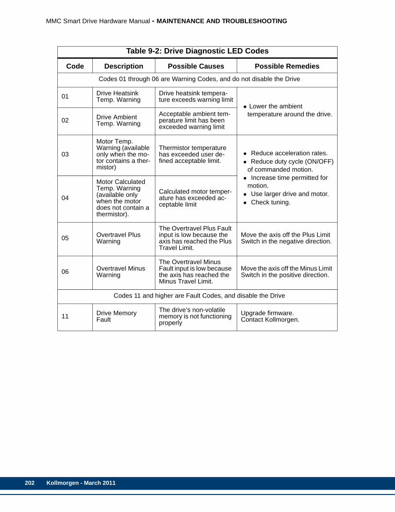
202
MMC Smart Drive Hardware Manual - MAINTENANCE AND TROUBLESHOOTING
Table 9-2: Drive Diagnostic LED Codes
Code Description Possible Causes Possible Remedies
Codes 01 through 06 are Warning Codes, and do not disable the Drive
01 Drive Heatsink Temp. Warning
Drive heatsink tempera-ture exceeds warning limit
• Lower the ambient temperature around the drive.
02 Drive Ambient Temp. Warning
Acceptable ambient tem-perature limit has been exceeded warning limit
03
Motor Temp. Warning (available only when the mo-tor contains a ther-mistor)
Thermistor temperature has exceeded user de-fined acceptable limit.
• Reduce acceleration rates.• Reduce duty cycle (ON/OFF)
of commanded motion.• Increase time permitted for
motion.• Use larger drive and motor.• Check tuning.
04
Motor Calculated Temp. Warning (available only when the motor does not contain a thermistor).
Calculated motor temper-ature has exceeded ac-ceptable limit
05 Overtravel Plus Warning
The Overtravel Plus Fault input is low because the axis has reached the Plus Travel Limit.
Move the axis off the Plus Limit Switch in the negative direction.
06 Overtravel Minus Warning
The Overtravel Minus Fault input is low because the axis has reached the Minus Travel Limit.
Move the axis off the Minus Limit Switch in the positive direction.
Codes 11 and higher are Fault Codes, and disable the Drive
11 Drive Memory Fault
The drive’s non-volatile memory is not functioning properly
Upgrade firmware.Contact Kollmorgen.
Kollmorgen - March 2011

MMC Smart Drive Hardware Manual - MAINTENANCE AND TROUBLESHOOTING
12 Drive Bus Over Voltage Fault
Excessive regeneration of power.The motor may regener-ate too much peak energy through the drive’s power supply. A fault is generat-ed to prevent overload.
Change the deceleration or mo-tion profile.Check shunt connections and where necessary, properly make connections.Reduce the reflected inertia of your mechanical system.Use a larger motor and/or drive.
Excessive AC input volt-age.
Verify input AC voltage is within specifications. Adjust according-ly.
Output short circuit.
Remove all power and motor connections, and perform a con-tinuity check from the DC bus to the U, V, and W motor outputs. If a continuity exists, check for wire fibers between terminals, con-tact Kollmorgen
Motor cabling wires short-ed together.
Disconnect motor power cables from the drive. Test the cables for short circuits. Replace cable if necessary.
Internal motor winding short circuit.
Disconnect motor power cables from the motor. If the motor is dif-ficult to turn by hand, it may need to be replaced. Test winding re-sistance to confirm short circuit.
230V motor used with a 460V drive and drive pow-ered at 460V.
Set the drive for operation at 230V and apply 230V power to the drive.
13 Drive PM1 Over Current Fault
Current feedback ex-ceeds the drive over cur-rent fault limit.
Adjust the over current fault limit.
Output short circuit.
Remove all power and motor connections, and perform a con-tinuity check from the DC bus to the U, V, and W motor outputs. If a short exists, check for wire fi-bers between terminals, contact Kollmorgen
Motor cabling wires short-ed together.
Disconnect motor power cables from the drive. If faults stop, re-place cable.
Internal motor winding short circuit.
Disconnect motor power cables from the motor. If the motor is dif-ficult to turn by hand, it may need to be replaced.
Table 9-2: Drive Diagnostic LED Codes (Continued)
Code Description Possible Causes Possible Remedies
Kollmorgen - March 2011 203
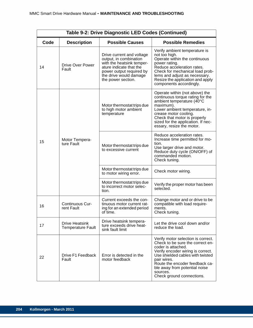
204
MMC Smart Drive Hardware Manual - MAINTENANCE AND TROUBLESHOOTING
14 Drive Over Power Fault
Drive current and voltage output, in combination with the heatsink temper-ature indicate that the power output required by the drive would damage the power section.
Verify ambient temperature is not too high.Operate within the continuous power rating.Reduce acceleration rates.Check for mechanical load prob-lems and adjust as necessary.Resize the application and apply components accordingly.
15 Motor Tempera-ture Fault
Motor thermostat trips due to high motor ambient temperature
Operate within (not above) the continuous torque rating for the ambient temperature (40°C maximum).Lower ambient temperature, in-crease motor cooling.Check that motor is properly sized for the application. If nec-essary, resize the motor.
Motor thermostat trips due to excessive current
Reduce acceleration rates.Increase time permitted for mo-tion.Use larger drive and motor.Reduce duty cycle (ON/OFF) of commanded motion.Check tuning.
Motor thermostat trips due to motor wiring error. Check motor wiring.
Motor thermostat trips due to incorrect motor selec-tion.
Verify the proper motor has been selected.
16 Continuous Cur-rent Fault
Current exceeds the con-tinuous motor current rat-ing for an extended period of time.
Change motor and or drive to be compatible with load require-ments.Check tuning.
17 Drive Heatsink Temperature Fault
Drive heatsink tempera-ture exceeds drive heat-sink fault limit
Let the drive cool down and/or reduce the load.
22 Drive F1 Feedback Fault
Error is detected in the motor feedback
Verify motor selection is correct.Check to be sure the correct en-coder is attached.Verify encoder wiring is correct.Use shielded cables with twisted pair wires.Route the encoder feedback ca-ble away from potential noise sources.Check ground connections.
Table 9-2: Drive Diagnostic LED Codes (Continued)
Code Description Possible Causes Possible Remedies
Kollmorgen - March 2011

MMC Smart Drive Hardware Manual - MAINTENANCE AND TROUBLESHOOTING
23 Drive Ambient Temp. Fault
Drive ambient tempera-ture exceeds the drive ambient temperature fault limit
Operate within (not above) the continuous rating for the ambient temperature.Lower ambient temperature, in-crease cabinet cooling.
24 Motor Calculated Temp. Fault
Motor calculated tempera-ture exceeds the motor calculated temperature fault limit.
Check the machine for exces-sive loads. Motor may be under-sized for the application.
25 Drive Timing Fault
Timing error is detected in the execution of the con-trol algorithms performed by the drive’s digital signal processor.
Contact Kollmorgen.
26 Drive Interface Fault
Communication error is detected in the transmis-sion of information be-tween the drive’s digital signal processor and the drive’s power section.
Contact Kollmorgen.
27 User Set Fault PiCPro Set User Fault command selected.
The PiCPro Set User Fault com-mand was selected or the Con-trol Panel mode was activated or deactivated while the drive was enabled.
31 Drive F1 Commu-nication Fault
Communication error is detected in the transmis-sion of information be-tween the drive and a high resolution or multi-turn ab-solute feedback device.
Check encoder line and make sure the correct encoder is at-tached.Verify encoder wiring is correct.Use shielded cables with twisted pair wires.Route the encoder feedback ca-ble away from potential noise sources.Check ground connections.Verify motor selection is correct.
Bad encoder. Replace motor and encoder.
32 Over Speed FaultUser specified motor speed has been exceed-ed.
Check cables for noise.Check tuning.
33 Over Current FaultUser-Specified average current level has been ex-ceeded.
Change to a less restrictive set-ting.Reduce the load.
34 Drive Communica-tion Fault
Communication error oc-curs while drive control is being performed using the PiCPro Control Panel tools.
Do not disconnect the PiCPro cable while operating in Control Panel Mode.
Table 9-2: Drive Diagnostic LED Codes (Continued)
Code Description Possible Causes Possible Remedies
Kollmorgen - March 2011 205
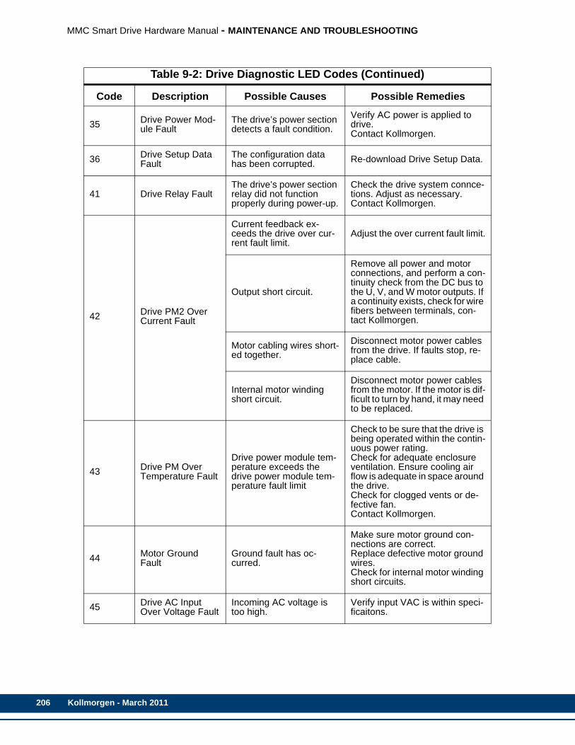
206
MMC Smart Drive Hardware Manual - MAINTENANCE AND TROUBLESHOOTING
35 Drive Power Mod-ule Fault
The drive’s power section detects a fault condition.
Verify AC power is applied to drive.Contact Kollmorgen.
36 Drive Setup Data Fault
The configuration data has been corrupted. Re-download Drive Setup Data.
41 Drive Relay FaultThe drive’s power section relay did not function properly during power-up.
Check the drive system connce-tions. Adjust as necessary.Contact Kollmorgen.
42 Drive PM2 Over Current Fault
Current feedback ex-ceeds the drive over cur-rent fault limit.
Adjust the over current fault limit.
Output short circuit.
Remove all power and motor connections, and perform a con-tinuity check from the DC bus to the U, V, and W motor outputs. If a continuity exists, check for wire fibers between terminals, con-tact Kollmorgen.
Motor cabling wires short-ed together.
Disconnect motor power cables from the drive. If faults stop, re-place cable.
Internal motor winding short circuit.
Disconnect motor power cables from the motor. If the motor is dif-ficult to turn by hand, it may need to be replaced.
43 Drive PM Over Temperature Fault
Drive power module tem-perature exceeds the drive power module tem-perature fault limit
Check to be sure that the drive is being operated within the contin-uous power rating.Check for adequate enclosure ventilation. Ensure cooling air flow is adequate in space around the drive.Check for clogged vents or de-fective fan.Contact Kollmorgen.
44 Motor Ground Fault
Ground fault has oc-curred.
Make sure motor ground con-nections are correct.Replace defective motor ground wires. Check for internal motor winding short circuits.
45 Drive AC Input Over Voltage Fault
Incoming AC voltage is too high.
Verify input VAC is within speci-ficaitons.
Table 9-2: Drive Diagnostic LED Codes (Continued)
Code Description Possible Causes Possible Remedies
Kollmorgen - March 2011
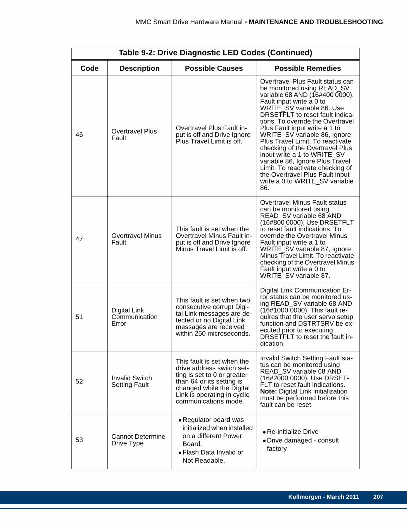
MMC Smart Drive Hardware Manual - MAINTENANCE AND TROUBLESHOOTING
46 Overtravel Plus Fault
Overtravel Plus Fault in-put is off and Drive Ignore Plus Travel Limit is off.
Overtravel Plus Fault status can be monitored using READ_SV variable 68 AND (16#400 0000). Fault input write a 0 to WRITE_SV variable 86. Use DRSETFLT to reset fault indica-tions. To override the Overtravel Plus Fault input write a 1 to WRITE_SV variable 86, Ignore Plus Travel Limit. To reactivate checking of the Overtravel Plus input write a 1 to WRITE_SV variable 86, Ignore Plus Travel Limit. To reactivate checking of the Overtravel Plus Fault input write a 0 to WRITE_SV variable 86.
47 Overtravel Minus Fault
This fault is set when the Overtravel Minus Fault in-put is off and Drive Ignore Minus Travel Limit is off.
Overtravel Minus Fault status can be monitored using READ_SV variable 68 AND (16#800 0000). Use DRSETFLT to reset fault indications. To override the Overtravel Minus Fault input write a 1 to WRITE_SV variable 87, Ignore Minus Travel Limit. To reactivate checking of the Overtravel Minus Fault input write a 0 to WRITE_SV variable 87.
51Digital LinkCommunication Error
This fault is set when two consecutive corrupt Digi-tal Link messages are de-tected or no Digital Link messages are received within 250 microseconds.
Digital Link Communication Er-ror status can be monitored us-ing READ_SV variable 68 AND (16#1000 0000). This fault re-quires that the user servo setup function and DSTRTSRV be ex-ecuted prior to executing DRSETFLT to reset the fault in-dication.
52 Invalid SwitchSetting Fault
This fault is set when the drive address switch set-ting is set to 0 or greater than 64 or its setting is changed while the Digital Link is operating in cyclic communications mode.
Invalid Switch Setting Fault sta-tus can be monitored using READ_SV variable 68 AND (16#2000 0000). Use DRSET-FLT to reset fault indications.Note: Digital Link initialization must be performed before this fault can be reset.
53 Cannot Determine Drive Type
•Regulator board was initialized when installed on a different Power Board.
•Flash Data Invalid or Not Readable,
•Re-initialize Drive•Drive damaged - consult
factory
Table 9-2: Drive Diagnostic LED Codes (Continued)
Code Description Possible Causes Possible Remedies
Kollmorgen - March 2011 207
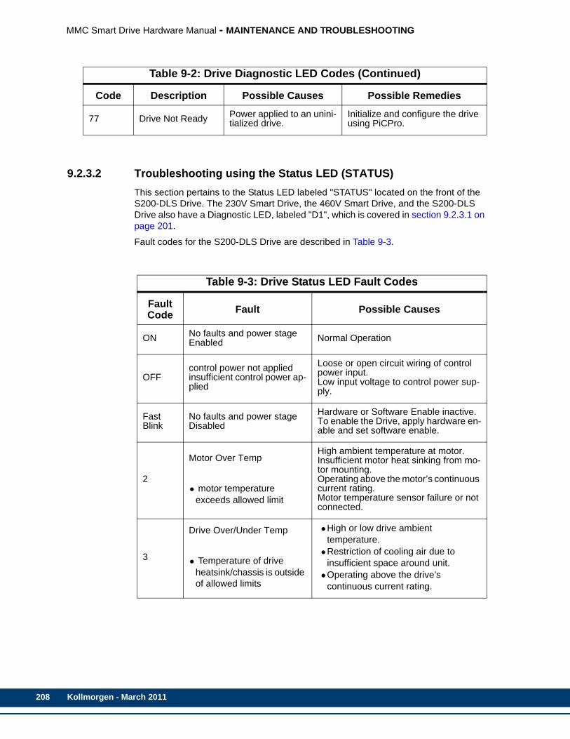
208
MMC Smart Drive Hardware Manual - MAINTENANCE AND TROUBLESHOOTING
9.2.3.2 Troubleshooting using the Status LED (STATUS)This section pertains to the Status LED labeled "STATUS" located on the front of the S200-DLS Drive. The 230V Smart Drive, the 460V Smart Drive, and the S200-DLS Drive also have a Diagnostic LED, labeled "D1", which is covered in section 9.2.3.1 on page 201.
Fault codes for the S200-DLS Drive are described in Table 9-3.
77 Drive Not Ready Power applied to an unini-tialized drive.
Initialize and configure the drive using PiCPro.
Table 9-3: Drive Status LED Fault Codes
Fault Code Fault Possible Causes
ON No faults and power stage Enabled Normal Operation
OFFcontrol power not appliedinsufficient control power ap-plied
Loose or open circuit wiring of control power input.Low input voltage to control power sup-ply.
Fast Blink
No faults and power stage Disabled
Hardware or Software Enable inactive. To enable the Drive, apply hardware en-able and set software enable.
2
Motor Over Temp
• motor temperature exceeds allowed limit
High ambient temperature at motor.Insufficient motor heat sinking from mo-tor mounting.Operating above the motor’s continuous current rating.Motor temperature sensor failure or not connected.
3
Drive Over/Under Temp
• Temperature of drive heatsink/chassis is outside of allowed limits
•High or low drive ambient temperature.
•Restriction of cooling air due to insufficient space around unit.
•Operating above the drive’s continuous current rating.
Table 9-2: Drive Diagnostic LED Codes (Continued)
Code Description Possible Causes Possible Remedies
Kollmorgen - March 2011

MMC Smart Drive Hardware Manual - MAINTENANCE AND TROUBLESHOOTING
4
Drive I*t Too High
•The product of the drives output current multiplied by time has exceeded allowed limits.
•If current foldback is enabled the drive peak output current automatically reduces to 0.67% of DIpeak. If foldback is not enabled, the drive will fault.
•Mechanically-jammed motor.•Motion profile acceleration requires
peak current for too long of a time duration.
•Machine load on the motor increased by friction.
•Wiring problem between drive and motor yielding improper motion.Motor commutation error.
•Drive under-sized for application, friction or load.
5
Motor I*I*t Too High
•Motor current amplitude squared multiplied by time has exceed allowed limits
•Mechanically-jammed motor.•Motion profile acceleration requires
peak current for too long of a time duration.
•Machine load on the motor increased by friction.
•Motor commutation error.•Motor under-sized for application,
friction or load.
6
Optional Battery low
•Optional fault used to indicate SFD battery supply voltage is low
•Battery low fault enabled and battery is not installed.
•SFD Battery backup voltage is low.
7
Bus Over Voltage - Self Re-setting
•The BUS voltage has exceed the upper threshold limit
•AC Line voltage is too high.•Regenative energy during
deceleration is causing the BUS to rise (possible remedy: add regen resistor).
9
Motor l-l or l-n Short
•Line-to-Line, Line-to-Neutral or Line-to-PE short on the motor output causing an instantaneous over current.
•Motor power wiring short circuit - line-to-ground /neutral.
•Motor cable short line-to-line.•Motor power cable length exceeds the
data sheet specification causing excessive motor line-to-earth ground/neutral capacitance.
•Internal motor winding short circuit.•Motor L too small.•KIP set too large.
Table 9-3: Drive Status LED Fault Codes (Continued)
Fault Code Fault Possible Causes
Kollmorgen - March 2011 209

210
MMC Smart Drive Hardware Manual - MAINTENANCE AND TROUBLESHOOTING
10 Output Over Current•Insufficient motor inductance•KIP or KII improperly set causing
excessive output current overshoots.
11
Hall Fault
•Valid only when drive is set for 6 Step (Hall feedback) operation.
•Invalid configuration.•Motor overspeed.•Invalid hall state.•Invalid hall transition.
12 SFD Configuration Error
•SFD UART error during SFD initialization.
•Bad motor data check sum.•The drive will attempt to initialize the
SFD up to 4 times. If it fails this error is reported.
13
J3 FB +5V Short
•Excessive current drain on SFD +5 supply output.
•Excessive loading on SFD +5 supply.•Short in the feedback cable on SFD
+5 (J3-1) to ground.
14
SFD Motor Data Error
•Motor data in SFD is outside drive limits or is inconsistent
•Motor and Drive are not compatible. Auto setup calculation yielded a desired parameter value outside valid range.
•Incorrect/inconsistent motor data loaded into the SFD.
15 SFD Sensor Failure Internal SFD failure.
Excessive electrical noise in the drive environment causing communications interference.
16 SFD UART Error Internal SFD failure.
17 SFD Communication Error
•Feedback cable not connected at the drive or at the motor.
•Feedback cable shield not connected.•Defective feedback cable•Internal SFD failure.•Excessive electrical noise in the drive
environment causing communications interference.
18 Option Card Watch Dog Time out Communication error between option card and main board.
Table 9-3: Drive Status LED Fault Codes (Continued)
Fault Code Fault Possible Causes
Kollmorgen - March 2011
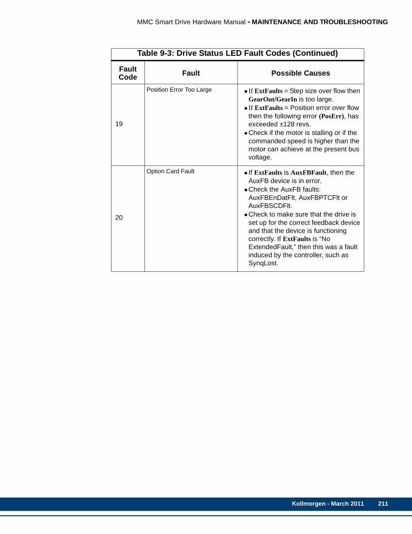
MMC Smart Drive Hardware Manual - MAINTENANCE AND TROUBLESHOOTING
19
Position Error Too Large •If ExtFaults = Step size over flow then GearOut/GearIn is too large.
•If ExtFaults = Position error over flow then the following error (PosErr), has exceeded ±128 revs.
•Check if the motor is stalling or if the commanded speed is higher than the motor can achieve at the present bus voltage.
20
Option Card Fault •If ExtFaults is AuxFBFault, then the AuxFB device is in error.
•Check the AuxFB faults: AuxFBEnDatFlt, AuxFBPTCFlt or AuxFBSCDFlt.
•Check to make sure that the drive is set up for the correct feedback device and that the device is functioning correctly. If ExtFaults is “No ExtendedFault,” then this was a fault induced by the controller, such as SynqLost.
Table 9-3: Drive Status LED Fault Codes (Continued)
Fault Code Fault Possible Causes
Kollmorgen - March 2011 211

212
MMC Smart Drive Hardware Manual - MAINTENANCE AND TROUBLESHOOTING
Kollmorgen - March 2011
MMC Smart Drive Hardware Manual - RESOLVER INTERFACE OPTION MODULE
10 Resolver Interface Option ModuleThe Resolver Interface Option module can be installed in the 230V or 460V Smart Drive. It cannot be installed in an S200-DLS Drive. This section describes the Resolver Interface Option Module in detail.
10.1 Theory of Operation The Resolver Interface Option Module provides the interface between the resolver and the drive’s DSP. It is a tracking system where the rotor is excited with a sine wave. The outputs of the resolver are amplitude modulated by the sine and cosine of the rotor shaft angle. The tracking converter converts the sine and cosine amplitude ratio into a 12 bit number.
The module provides a 4 Vrms 5 kHz sine wave to excite the resolver rotor. The resolver transformer ratio is .5:1 so the stator outputs are 2V RMS with the shaft rotated to the angle of maximum coupling. The sine and cosine rotor outputs are returned to the resolver module’s twin instrumentation amplifier inputs to produce a high common mode noise rejection and a high input impedance (220K Ω). The sine and cosine signals are then fed to a resolver to digital converter chip that performs the tracking conversion. The converter has both a serial output and an encoder emulator output. The serial output is read when the drive is powered up to obtain the absolute commutation angle for the motor. Thereafter, it is used as an encoder emulator.
The module is able to detect a loss of feedback by monitoring the sine and cosine signals. If both are near zero at the same time, a loss of feedback error is generated.
10.2 Installing the Resolver Module1. If the Resolver Module is being installed in a 230V drive, remove the five screws
at the corners of the cover and remove the cover. If the Resolver Module is being installed in a 460V drive, turn the 2 locking screws on the front of the drive clock-wise and remove the MMC Smart Drive board from the drive chassis.
2. Remove the shunt from the 24-pin DIP socket located on the MMC Smart Drive board (See Figure 10-1 on page 214).
3. If there are not two standoffs already installed on either side of the 24-pin DIP socket on the MMC Smart Drive board, proceed to step 10.
4. If there are nylon standoffs snapped into the Resolver Module, remove and dis-card them. If there are nylon standoffs included with the Resolver Module, discard them.
5. Remove and save the two nylon screws that are threaded into the standoffs mounted to the MMC Smart Drive board.
6. Position the Resolver Module so the mounting holes align with the standoffs, and the header is aligned with the socket (See Figure1 10-2 on page 215).
7. Using even pressure, press the option module into place.
8. Screw the Resolver Module to the standoffs using the screws removed in step 5.
9. Verify that the module is fully seated into the socket and proceed to step 15.
10. If there are standoffs installed in the Resolver Module, proceed to step 12.
11. Install the snap-in standoffs that were included with the Resolver Module into the Resolver Module. From the back of the Resolver Module (the side that has the 24-pin header on it), insert the short (slotted) end of the standoffs into the mounting holes.
Kollmorgen - March 2011 213
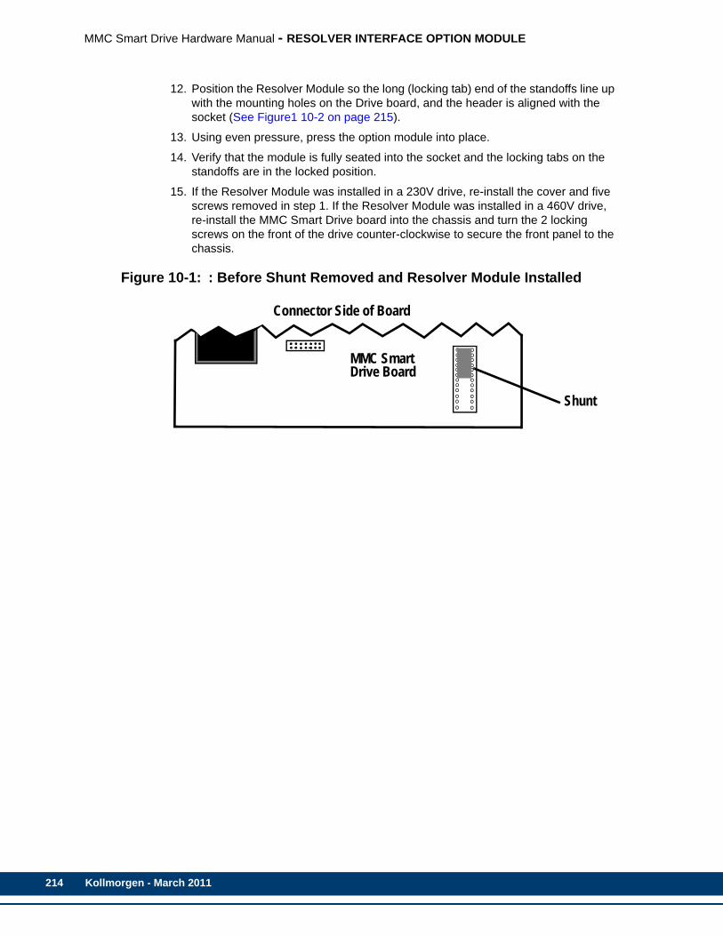
214
MMC Smart Drive Hardware Manual - RESOLVER INTERFACE OPTION MODULE
12. Position the Resolver Module so the long (locking tab) end of the standoffs line up with the mounting holes on the Drive board, and the header is aligned with the socket (See Figure1 10-2 on page 215).
13. Using even pressure, press the option module into place.
14. Verify that the module is fully seated into the socket and the locking tabs on the standoffs are in the locked position.
15. If the Resolver Module was installed in a 230V drive, re-install the cover and five screws removed in step 1. If the Resolver Module was installed in a 460V drive, re-install the MMC Smart Drive board into the chassis and turn the 2 locking screws on the front of the drive counter-clockwise to secure the front panel to the chassis.
Figure 10-1: : Before Shunt Removed and Resolver Module Installed
ResolverBoard
MMC SmartDrive Board
Shunt
Connector Side of Board
Kollmorgen - March 2011
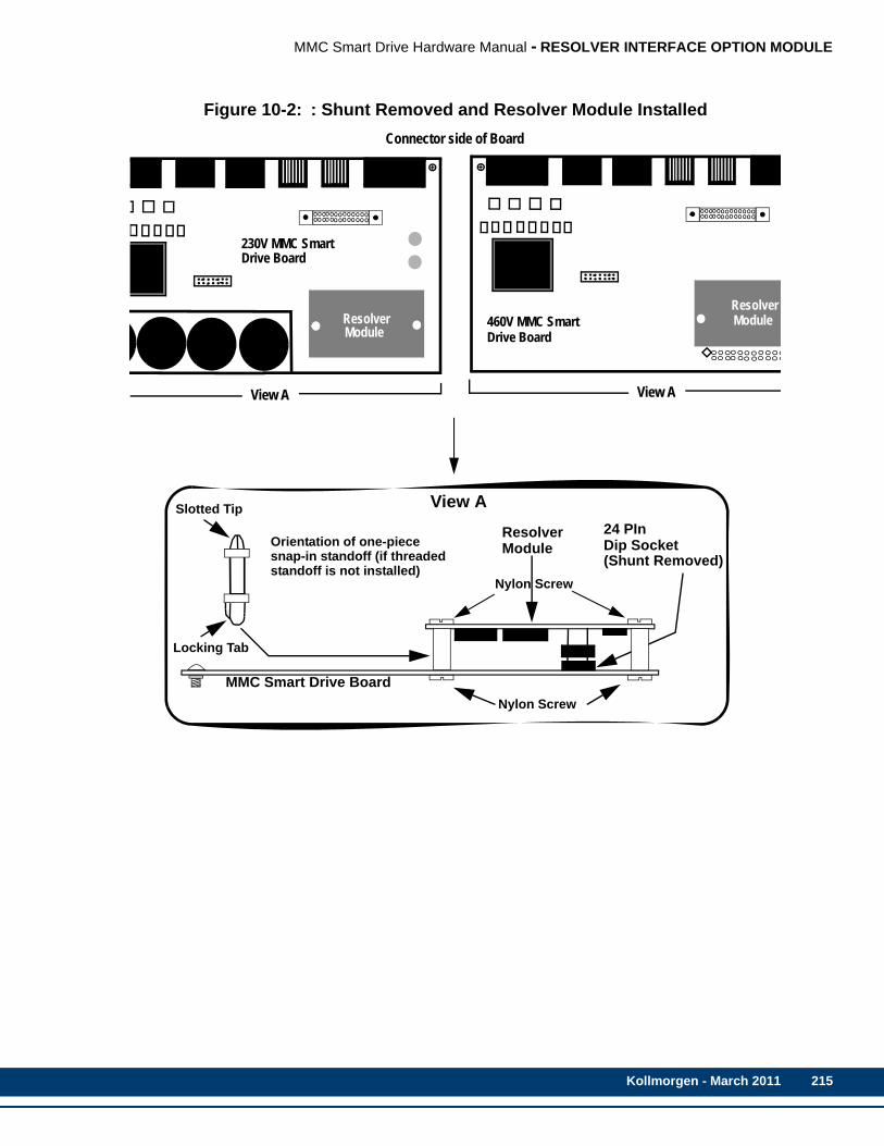
MMC Smart Drive Hardware Manual - RESOLVER INTERFACE OPTION MODULE
Figure 10-2: : Shunt Removed and Resolver Module Installed
ResolverModule
230V MMC SmartDrive Board
View A
ResolverModule460V MMC Smart
Drive Board
Connector side of Board
View A
MMC Smart Drive Board
Resolver
Nylon Screw
24 PInDip SocketModule(Shunt Removed)
View A
Nylon Screw
Locking Tab
Slotted Tip
Orientation of one-piecesnap-in standoff (if threadedstandoff is not installed)
Kollmorgen - March 2011 215
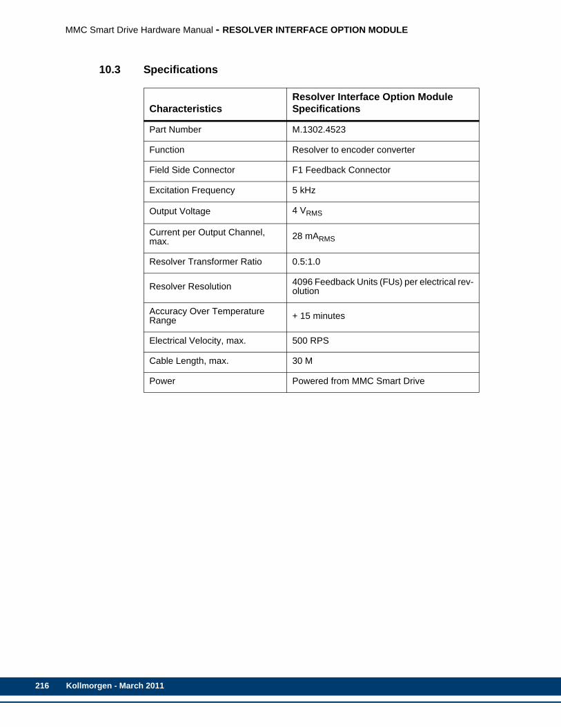
216
MMC Smart Drive Hardware Manual - RESOLVER INTERFACE OPTION MODULE
10.3 Specifications
CharacteristicsResolver Interface Option Module Specifications
Part Number M.1302.4523
Function Resolver to encoder converter
Field Side Connector F1 Feedback Connector
Excitation Frequency 5 kHz
Output Voltage 4 VRMS
Current per Output Channel, max. 28 mARMS
Resolver Transformer Ratio 0.5:1.0
Resolver Resolution 4096 Feedback Units (FUs) per electrical rev-olution
Accuracy Over Temperature Range + 15 minutes
Electrical Velocity, max. 500 RPS
Cable Length, max. 30 M
Power Powered from MMC Smart Drive
Kollmorgen - March 2011
MMC Smart Drive Hardware Manual - DRIVE RESIDENT DIGITAL MMC CONTROL
11 Drive Resident Digital MMC ControlThe Drive Resident Digital MMC Control can be installed in the 230V or 460V Smart Drive. It cannot be installed in an S200-DLS Drive. This section describes the Drive Resident Digital MMC Control in detail.
11.1 IntroductionThis section contains information for the Drive Resident Digital MMC Control (Digital MMC-Dx). Block I/O information can be found in the Block I/O Modules Manual. Software information can be found in the PiCPro Online Help, the Function/Function Block Reference Guide, ASFB Manuals or on-line.
11.1.1 OverviewThe Drive Resident Digital MMC Control offers a complete solution to both machine and motion control in a module that is installed into any Digital Interfaced Smart Drive (MMC-SD-D) except the 230V Narrow Drive (-DN). One Drive Resident Digital MMC Control can control from 1 to 16 drives as follows:
• Digital MMC-D1 (controls one MMC-SD-D)
• Digital MMC- D2 (controls two MMC-SD-D)
• Digital MMC- D4 (controls four MMC-SD-D)
• Digital MMC- D8 (controls eight MMC-SD-D)
• Digital MMC- D16 (controls 16 MMC-SD-D)
PiCPro is used to program the Drive Resident Digital MMC Control. The built-in I/O (eight 24VDC inputs and eight 24VDC outputs) can be expanded using Kollmorgen serially distributed block I/O (not included on the Digital MMC-D1).
11.1.2 Major ComponentsThe Drive Resident Digital MMC Control contains the CPU, a User Serial port, a Block I/O port, an Ethernet port, and a General I/O port consisting of 8 DC inputs and 8 DC outputs.
Kollmorgen - March 2011 217

218
MMC Smart Drive Hardware Manual - DRIVE RESIDENT DIGITAL MMC CONTROL
Figure 11-1: The Drive Resident Digital MMC Control
* The Block I/O Port connector (C1), Ethernet Communications Port connector (C4), Ethernet Link LED, and Ethernet Activity LED are present on the Digital MMC-D1 Control, but are not functional.
Diagnostic LED (D2)(Yellow)
User Serial Port (C3)(15-Pin High Density D-Shell)
Block I/O Port (C1)*(9-Pin Standard D-Shell)
Scan LED (S)(Green)
Ethernet Communications Port (C4)*(RJ-45 8-Pin)
General I/O Port (C5)(26-Pin High Density D-Shell)
Ethernet Activity LED*(Green)
Ethernet Link LED*(Green)
Kollmorgen - March 2011
MMC Smart Drive Hardware Manual - DRIVE RESIDENT DIGITAL MMC CONTROL
11.2 Installing the Drive Resident Digital MMC Control
11.2.1 Installing into a 230V MMC-SD Drive1. Remove the three screws from the right side of the cover and one screw from the
top and bottom of the drive near the front. Remove the cover.
2. Place the cover removed in step 1 on a flat surface, with the blue plastic faceplate down, and the large side cover to the left pointing up.
3. Remove the two screws that hold the .6" by 8" blue filler plate to the back of the faceplate and remove the plate.
4. Locate the 4 screws that secure the top-most printed circuit board into the drive. Remove one of the screws and the associated lock washer, and install one of the four threaded standoffs that were included with the Drive Resident Digital MMC Control (do not use the lock washer). Repeat this process for the other 3 screws, one at a time.
5. Place the Drive Resident Digital MMC Control into the drive, with the connectors facing towards the front of the unit. Align the 20-pin connector on the Drive Resi-dent Digital MMC Control with the 20-pin connector on the drive. Press the Drive Resident Digital MMC Control onto the drive until the 20-pin connector is com-pletely seated and the Drive Resident Digital MMC Control is seated against the threaded standoffs installed in step 4.
6. Fasten the Drive Resident Digital MMC Control onto the threaded standoffs using the lockwashers and screws removed in step 4.
7. Replace the cover using the 4 screws removed in step 1.
11.2.2 Installing into a 460V MMC-SD Drive1. Turn the two locking screws on the front of the drive clockwise ¼ turn and pull the
drive control board unit out of the drive.
2. Place the drive control board unit removed in step 1 on a flat surface, with the blue plastic faceplate down, and the drive control board to the left.
3. Remove the two screws that hold the .6" by 8" blue filler plate and remove the plate.
4. Place the drive control board unit on a flat surface so that the control board is fac-ing up, and the blue plastic faceplate is facing away from you.
5. Locate the 4 screws that secure the top-most printed circuit board into the drive. Remove one of the screws and the associated lock washer, and install one of the four threaded standoffs that were included with the Drive Resident Digital MMC Control (do not use the lock washer). Repeat this process for the other 3 screws, one at a time.
6. Place the control board unit on a flat surface, with the blue plastic faceplate down, and the drive control board to the left.
7. Loosen (but do not remove….about 2 turns) the 5 screws that hold the drive con-trol board mounting plate to the front cover plate.
8. Place the Drive Resident Digital MMC Control into the drive, inserting the connec-tors on the Drive Resident Digital MMC Control through the front plate.
9. Align the 20-pin connector on the Drive Resident Digital MMC Control with the 20-pin connector on the drive. Press the Drive Resident Digital MMC Control onto the
Kollmorgen - March 2011 219

220
MMC Smart Drive Hardware Manual - DRIVE RESIDENT DIGITAL MMC CONTROL
drive until the 20-pin connector is completely seated and the Drive Resident Digi-tal MMC Control is seated against the threaded standoffs installed in step 5.
10. Tighten the 5 screws loosened in step 7
11. Fasten the Drive Resident Digital MMC Control onto the threaded standoffs using the lockwashers and screws removed in step 5.
12. Replace the control board unit back into the drive, and turn the locking screws ¼ turn counter-clockwise to secure the unit in place.
11.3 System Wiring GuidelinesThe Drive Resident Digital MMC Control relies on electrical signals to report what is going on in the application and to send commands to it. In addition, signals are constantly being exchanged within the system. The Drive Resident Digital MMC Control is designed for use in industrial environments, but some guidelines should be followed.
Figure 11-2: Recommended EMC Compliant Connections
Inside a control cabinet, connect the shields of shielded cables. The two different methods of terminating shields are used to accommodate two different immunity requirements. Immunity required inside an enclosure is considered lower because cables are typically less than three meters in length and/or can be separated from each other and from noise sources.
Immunity required external to an enclosure is considered higher because the user may have less control over the noise environment. Low level signal cables that can be external to an enclosure are tested at a 2 KV level for electrical fast transients (EFTs).
MMC
COMMUNICATIONS
DC INPUT/OUTPUT
24V
CO
M
AC INPUTPOWER
GND
SINGLE-POINT GROUND
SINGLE-POINT GROUND
DC POWER SUPPLY+
PowerConnector
Capacitor
SmartDriveControl
Kollmorgen - March 2011

MMC Smart Drive Hardware Manual - DRIVE RESIDENT DIGITAL MMC CONTROL
Low level signals that can be less than three meters in length or can be separated from noise sources are tested at a 1 KV level. Under the stated conditions, there will be no disturbance of digital I/O, encoder, or encoder operation. For analog signals, there may be momentary disturbances but there will be self-recovery when the noise subsides.
Do not operate transmitters, arc welding equipment, or other high noise radiators within one meter of an enclosure that has the door open. Continue to equip inductive devices, if they are in series with a mechanical contact or switch, with arc suppression circuits. These devices include contactors, solenoids and motors. Shield all cables that carry heavy current near the system, using continuous foil wrap or conduit grounded at both ends. Such cables include power leads for high-frequency welders and for pulse-width-modulated motor drives.
11.4 Starting an OperationGood procedure suggests that the system should be tested each time a new application is powered up. The Diagnostic LED (D2) on the Drive Resident Digital MMC Control should be off indicating that the diagnostic tests were passed.
Turn off the main disconnect switch and plug the DC connector into the power connector on the MMC-SD. Turn on input power. The D2 LED turns on and then turns off when the Drive Resident Digital MMC Control passes its diagnostic tests.
11.4.1 Connecting the Drive Resident Digital MMC Control to the Applica-tion1. Turn off the main disconnect switch in the control cabinet. If some devices are not
powered from the control cabinet, turn them off also.
2. Connect the connectors according to your diagrams.
3. Turn on power to the system. The PWR light on the MMC-SD goes on and stays on. The D2 light goes on, then goes off in turn. The SCAN (S) light goes on.The application starts to work under control of the system.
4. If an application program is not in system memory, use the download command in the PiCPro software to place it there.
11.4.2 Basic Setup and Maintenance ProceduresTable 11-1 below summarizes how to proceed when performing certain maintenance and/or setup functions.
WARNING
Use care when wiring I/O devices to the Drive Resident Digital MMC Controland when plugging in cables. Wiring the wrong device to the connector orplugging a connector into the wrong location could cause intermittent or in-correct machine operation.
Kollmorgen - March 2011 221
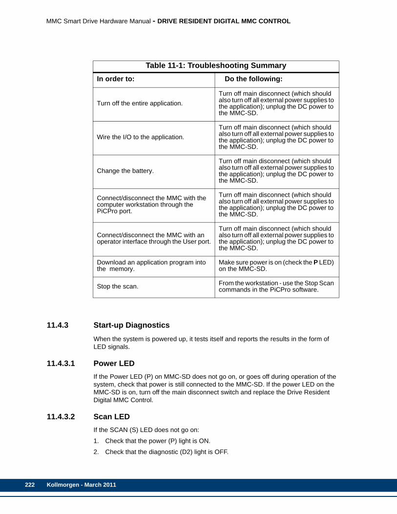
222
MMC Smart Drive Hardware Manual - DRIVE RESIDENT DIGITAL MMC CONTROL
11.4.3 Start-up DiagnosticsWhen the system is powered up, it tests itself and reports the results in the form of LED signals.
11.4.3.1 Power LEDIf the Power LED (P) on MMC-SD does not go on, or goes off during operation of the system, check that power is still connected to the MMC-SD. If the power LED on the MMC-SD is on, turn off the main disconnect switch and replace the Drive Resident Digital MMC Control.
11.4.3.2 Scan LEDIf the SCAN (S) LED does not go on:
1. Check that the power (P) light is ON.
2. Check that the diagnostic (D2) light is OFF.
Table 11-1: Troubleshooting SummaryIn order to: Do the following:
Turn off the entire application.Turn off main disconnect (which should also turn off all external power supplies to the application); unplug the DC power to the MMC-SD.
Wire the I/O to the application.Turn off main disconnect (which should also turn off all external power supplies to the application); unplug the DC power to the MMC-SD.
Change the battery.Turn off main disconnect (which should also turn off all external power supplies to the application); unplug the DC power to the MMC-SD.
Connect/disconnect the MMC with the computer workstation through the PiCPro port.
Turn off main disconnect (which should also turn off all external power supplies to the application); unplug the DC power to the MMC-SD.
Connect/disconnect the MMC with an operator interface through the User port.
Turn off main disconnect (which should also turn off all external power supplies to the application); unplug the DC power to the MMC-SD.
Download an application program into the memory.
Make sure power is on (check the P LED) on the MMC-SD.
Stop the scan. From the workstation - use the Stop Scan commands in the PiCPro software.
Kollmorgen - March 2011

MMC Smart Drive Hardware Manual - DRIVE RESIDENT DIGITAL MMC CONTROL
11.4.3.3 Drive Resident Digital MMC Control Start-Up Diagnostic LEDsThe LED D2 light on the Drive Resident Digital MMC Control lights up briefly while its diagnostic tests are running and then goes off. If D2 remains on, the Drive Resident Digital MMC Control has failed one of its tests. Follow these steps:
1. Turn off power to the system and to the application.
2. If the I/O wiring is connected, remove the connector.
3. Remove the defective Drive Resident Digital MMC Control from the drive.
4. Replace with a new Drive Resident Digital MMC Control. Connect the I/O wiring.
5. Turn on power to check diagnostics again.
NOTE
Diagnostics are run only when the system is powered up. It is possible thata failure might occur during operation. If so, D2 remains off. If you suspectthat a module might be defective, cycle power to run diagnostics again.
Kollmorgen - March 2011 223

224
MMC Smart Drive Hardware Manual - DRIVE RESIDENT DIGITAL MMC CONTROL
11.4.4 MMC Run-Time DiagnosticsWhile the Drive Resident Digital MMC Control is running, other tests are performed on a regular basis with their results also reported by D2.
While the Drive Resident Digital MMC Control is running, the D2 will flash a three digit code signal if there is an error. For example, if there is a long pause-flash-pause-flash-flash-pause-flash-flash-flash-long pause, the code is 123.
Table 11-2: MMC Error Codes
Code Error Description
123 Scan too long
A ladder scan loss has occurred because the CPU takes more than 200 ms to scan the application pro-gram.Whenever the scan light is out, the discrete outputs go to the OFF state and the analog outputs are ze-roed.
124 Excessive over-head The system overhead update time is excessive.
125 Insufficient memo-ry
There is insufficient memory on the CPU to run the current program.
126 No hardware bit memory
There is no bit memory installed on the CPU and the program requires it.
127 No software bit memory
There is no bit memory capability via software and the program requires it.
222 Driver error No driver support on the CPU for the I/O module. Update your system EPROMs.
22_ Master rack errorThe I/O modules in the master rack do not match what was declared in the hardware master declara-tion table. The number of flashes in the third digit (_) identifies the slot number that is in error.
232 Communications error
A failure has occurred in remote I/O communica-tions.
3_ _ Expansion rack error
The I/O modules in the block I/O modules do not match what was declared in the expansion hard-ware declaration table. For block I/O modules:The number of flashes in the second and third digits indicates the block I/O module (01 through 77). The second digit will flash a 1 - 7, 10 for 0. The third digit will flash a 1 - 9, 10 for 0. For example, if the second digit flashes 3 times and the third digit flashes 10 times, the module is 30.
621 Low Battery The battery on the Control is near its end of life, and needs to be replaced.
Kollmorgen - March 2011
MMC Smart Drive Hardware Manual - DRIVE RESIDENT DIGITAL MMC CONTROL
11.5 Connectors & OperationKollmorgen provides many optional accessories that simplify wiring the Drive Resident Digital MMC Control to external devices.
These accessories include cables to connect MMC-SD drives together and breakout boxes that provide screw-terminal connections to the Drive Resident Digital MMC Control. Contact Kollmorgen for further information.
11.5.1 PiCPro Port (P1)The PiCPro Port (P1) connector provides serial communication for the PiCPro programming interface. PiCPro Port (P1) is physically located on the MMC-SD faceplate. Refer to Chapter 5 for information on the PiCPro (P1) Port.
Note: PiCPro can also be run over from the Ethernet (C4) connector.
11.5.2 Block I/O Port (C1)The 9-pin female D-sub PiCPro Port connector (labeled “C1” on the front of the Control) provides serial communication between 1 to 77 Block I/O modules and the Control. Cables connecting the Control to the first Block I/O Module and between Block I/O modules can be up to 200 feet in length.
Note: The Block I/O Port (C1) is not included on the DigitalMMC-D1.
• Pin descriptions for are provided in Table 11-3.
• Pin assignments are provided in Table 11-4.
• The available Flying Lead cable is described in Table 11-5.
• Connections to the Block I/O Module are described in Table 11-6.
• Available Breakout Boxes and Cables are described in Table 11-7.
• Breakout Box dimensions are shown in Figure 11-3
Kollmorgen - March 2011 225

226
MMC Smart Drive Hardware Manual - DRIVE RESIDENT DIGITAL MMC CONTROL
.
Table 11-3: Block I/O Port Pin DescriptionsFunction Notes Pin
Transmit Data + Transmits data to Block I/O Modules. 3
Transmit Data - Transmits data to Block I/O Modules. 4
Receive Data + Receives data from Block I/O Modules. 5
Receive Data - Receives data from Block I/O Modules. 6
Shield Ground Provides a path for shield current through the chassis to an external single point ground. 7 & Shell
Table 11-4: Block I/O Port Pin AssignmentPin Signal In/Out Connector Pinout
1 NC N/A
9-pin female D-sub2 N/C N/A
3 Transmit Data + Out
4 Transmit Data - Out
5 Receive Data + In
6 Receive Data - In
7 Shield In
8 NC N/A
9 NC N/A
Connector Shell Drain In
NOTE
Pin 7 of the Block I/O port connector is connected to the connector shell with-in the MMC. Therefore, the shield may be connected to either pin 7 or theconnector shell.
6
59
1
Kollmorgen - March 2011

MMC Smart Drive Hardware Manual - DRIVE RESIDENT DIGITAL MMC CONTROL
Table 11-5: Block I/O Port to Flying Lead CablePart Number: M.1016.2568Length: 3 M (10 ft)Cable type: 24 AWG, twisted pair (individually shielded), 4 conductor.
9-Pin male D-sub (to Block I/O Port, face view)
Pin Signal Color Notes
3 Transmit Data + White Twisted
4 Transmit Data - Black Pair
7 Shield N/A with Shield
5 Receive Data + Red Twisted
6 Receive Data - Black Pair
7 Shield N/A with Shield
1
9 5
6
Kollmorgen - March 2011 227
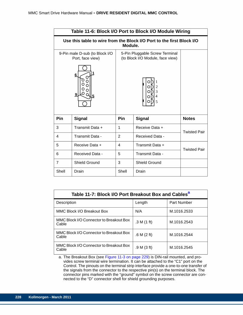
228
MMC Smart Drive Hardware Manual - DRIVE RESIDENT DIGITAL MMC CONTROL
Table 11-6: Block I/O Port to Block I/O Module Wiring
Use this table to wire from the Block I/O Port to the first Block I/O Module.
9-Pin male D-sub (to Block I/O Port, face view)
5-Pin Pluggable Screw Terminal (to Block I/O Module, face view)
Pin Signal Pin Signal Notes
3 Transmit Data + 1 Receive Data +Twisted Pair
4 Transmit Data - 2 Received Data -
5 Receive Data + 4 Transmit Data +Twisted Pair
6 Received Data - 5 Transmit Data -
7 Shield Ground 3 Shield Ground
Shell Drain Shell Drain
Table 11-7: Block I/O Port Breakout Box and Cablesa
a. The Breakout Box (see Figure 11-3 on page 229) is DIN-rail mounted, and pro-vides screw terminal wire termination. It can be attached to the “C1” port on the Control. The pinouts on the terminal strip interface provide a one-to-one transfer of the signals from the connector to the respective pin(s) on the terminal block. The connector pins marked with the “ground” symbol on the screw connector are con-nected to the “D” connector shell for shield grounding purposes.
Description Length Part Number
MMC Block I/O Breakout Box N/A M.1016.2533
MMC Block I/O Connector to Breakout Box Cable .3 M (1 ft) M.1016.2543
MMC Block I/O Connector to Breakout Box Cable .6 M (2 ft) M.1016.2544
MMC Block I/O Connector to Breakout Box Cable .9 M (3 ft) M.1016.2545
1
9 5
6
12345
Kollmorgen - March 2011
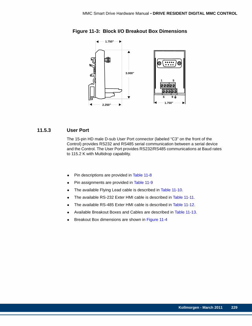
MMC Smart Drive Hardware Manual - DRIVE RESIDENT DIGITAL MMC CONTROL
Figure 11-3: Block I/O Breakout Box Dimensions
11.5.3 User PortThe 15-pin HD male D-sub User Port connector (labeled “C3” on the front of the Control) provides RS232 and RS485 serial communication between a serial device and the Control. The User Port provides RS232/RS485 communications at Baud rates to 115.2 K with Multidrop capability.
• Pin descriptions are provided in Table 11-8
• Pin assignments are provided in Table 11-9
• The available Flying Lead cable is described in Table 11-10.
• The available RS-232 Exter HMI cable is described in Table 11-11.
• The available RS-485 Exter HMI cable is described in Table 11-12.
• Available Breakout Boxes and Cables are described in Table 11-13.
• Breakout Box dimensions are shown in Figure 11-4
1.750”
2.250”
3.000”
1
6
1.750”
5
9
Kollmorgen - March 2011 229
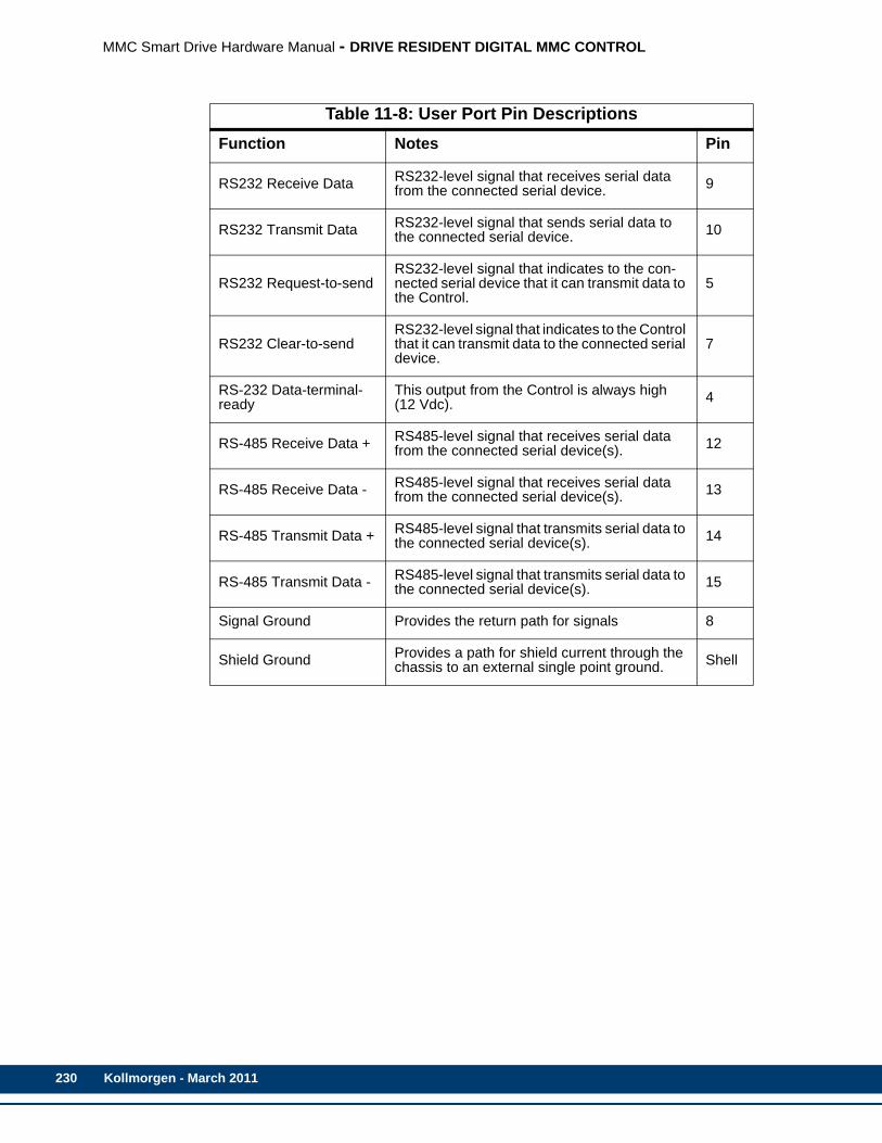
230
MMC Smart Drive Hardware Manual - DRIVE RESIDENT DIGITAL MMC CONTROL
Table 11-8: User Port Pin DescriptionsFunction Notes Pin
RS232 Receive Data RS232-level signal that receives serial data from the connected serial device. 9
RS232 Transmit Data RS232-level signal that sends serial data to the connected serial device. 10
RS232 Request-to-sendRS232-level signal that indicates to the con-nected serial device that it can transmit data to the Control.
5
RS232 Clear-to-sendRS232-level signal that indicates to the Control that it can transmit data to the connected serial device.
7
RS-232 Data-terminal-ready
This output from the Control is always high(12 Vdc). 4
RS-485 Receive Data + RS485-level signal that receives serial data from the connected serial device(s). 12
RS-485 Receive Data - RS485-level signal that receives serial data from the connected serial device(s). 13
RS-485 Transmit Data + RS485-level signal that transmits serial data to the connected serial device(s). 14
RS-485 Transmit Data - RS485-level signal that transmits serial data to the connected serial device(s). 15
Signal Ground Provides the return path for signals 8
Shield Ground Provides a path for shield current through the chassis to an external single point ground. Shell
Kollmorgen - March 2011
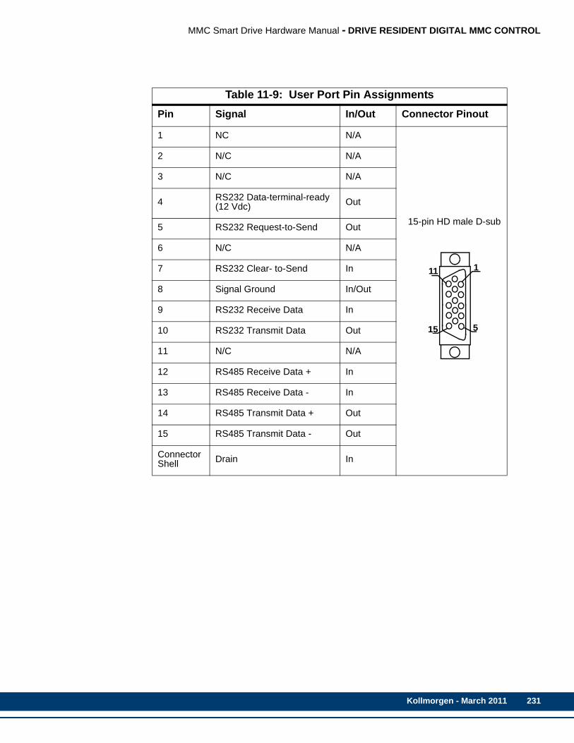
MMC Smart Drive Hardware Manual - DRIVE RESIDENT DIGITAL MMC CONTROL
Table 11-9: User Port Pin AssignmentsPin Signal In/Out Connector Pinout
1 NC N/A
15-pin HD male D-sub
2 N/C N/A
3 N/C N/A
4 RS232 Data-terminal-ready(12 Vdc) Out
5 RS232 Request-to-Send Out
6 N/C N/A
7 RS232 Clear- to-Send In
8 Signal Ground In/Out
9 RS232 Receive Data In
10 RS232 Transmit Data Out
11 N/C N/A
12 RS485 Receive Data + In
13 RS485 Receive Data - In
14 RS485 Transmit Data + Out
15 RS485 Transmit Data - Out
Connector Shell Drain In
5
1
15
11
Kollmorgen - March 2011 231
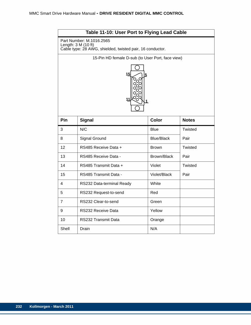
232
MMC Smart Drive Hardware Manual - DRIVE RESIDENT DIGITAL MMC CONTROL
Table 11-10: User Port to Flying Lead CablePart Number: M.1016.2565Length: 3 M (10 ft)Cable type: 28 AWG, shielded, twisted pair, 16 conductor.
15-Pin HD female D-sub (to User Port, face view)
Pin Signal Color Notes
3 N/C Blue Twisted
8 Signal Ground Blue/Black Pair
12 RS485 Receive Data + Brown Twisted
13 RS485 Receive Data - Brown/Black Pair
14 RS485 Transmit Data + Violet Twisted
15 RS485 Transmit Data - Violet/Black Pair
4 RS232 Data-terminal Ready White
5 RS232 Request-to-send Red
7 RS232 Clear-to-send Green
9 RS232 Receive Data Yellow
10 RS232 Transmit Data Orange
Shell Drain N/A
5
1
15
11
Kollmorgen - March 2011
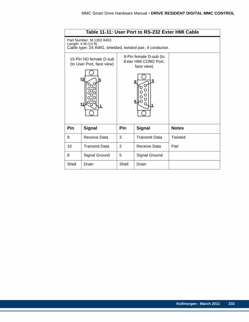
MMC Smart Drive Hardware Manual - DRIVE RESIDENT DIGITAL MMC CONTROL
Table 11-11: User Port to RS-232 Exter HMI CablePart Number: M.1302.8453Length: 4 M (13 ft)Cable type: 24 AWG, shielded, twisted pair, 4 conductor.
15-Pin HD female D-sub (to User Port, face view)
9-Pin female D-sub (to Exter HMI COM2 Port,
face view)
Pin Signal Pin Signal Notes
9 Receive Data 3 Transmit Data Twisted
10 Transmit Data 2 Receive Data Pair
8 Signal Ground 5 Signal Ground
Shell Drain Shell Drain
5
1
15
116
59
1
Kollmorgen - March 2011 233

234
MMC Smart Drive Hardware Manual - DRIVE RESIDENT DIGITAL MMC CONTROL
Table 11-12: User Port to RS-485 Exter HMI CablePart Number: M.1302.8454Length: 4 M (13 ft)Cable type: 24 AWG, shielded, twisted pair, 6 conductor.
15-Pin HD female D-sub (to User Port, face view)
25-Pin male D-sub (to Exter HMI COM1 Port,
face view)
Pin Signal Pin Signal Notes
12 Receive Data+ 2 Transmit Data+ Twisted
13 Receive Data- 15 Transmit Data- Pair
14 Transmit Data+ 3 Receive Data+ Twisted
15 Transmit Data- 16 Receive Data- Pair
8 Signal Ground 7 Signal Ground
Shell Drain Shell Drain
Table 11-13: User Port Breakout Box and Cablesa
a. The Breakout Box (see Figure 11-4 on page 235) is DIN-rail mounted, and pro-vides screw terminal wire termination. It can be attached to the “C3” connector on the Control. The pinouts on the terminal strip interface provide a one-to-one transfer of the signals from the connector to the respective pin(s) on the terminal block. The connector pins marked with the “ground” symbol on the screw connec-tor are connected to the “D” connector shell for shield grounding purposes.
Description Length Part Number
MMC User Port Breakout Box N/A M.1016.2530
MMC User Port to Breakout Box Cable .3 M (1 ft) M.1016.2715
MMC User Port to Breakout Box Cable .6 M (2 ft) M.1016.2716
MMC User Port to Breakout Box Cable .9 M (3 ft) M.1016.2717
5
1
15
11
1
25 13
14
Kollmorgen - March 2011
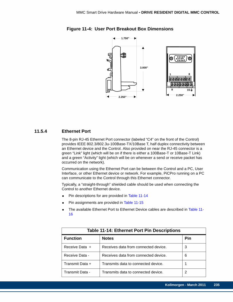
MMC Smart Drive Hardware Manual - DRIVE RESIDENT DIGITAL MMC CONTROL
Figure 11-4: User Port Breakout Box Dimensions
11.5.4 Ethernet PortThe 8-pin RJ-45 Ethernet Port connector (labeled “C4” on the front of the Control) provides IEEE 802.3/802.3u-100Base-TX/10Base T, half duplex connectivity between an Ethernet device and the Control. Also provided on near the RJ-45 connector is a green “Link” light (which will be on if there is either a 100Base-T or 10Base-T Link) and a green “Activity” light (which will be on whenever a send or receive packet has occurred on the network).
Communication using the Ethernet Port can be between the Control and a PC, User Interface, or other Ethernet device or network. For example, PiCPro running on a PC can communicate to the Control through this Ethernet connector.
Typically, a “straight-through” shielded cable should be used when connecting the Control to another Ethernet device.
• Pin descriptions for are provided in Table 11-14
• Pin assignments are provided in Table 11-15
• The available Ethernet Port to Ethernet Device cables are described in Table 11-16
Table 11-14: Ethernet Port Pin DescriptionsFunction Notes Pin
Receive Data + Receives data from connected device. 3
Receive Data - Receives data from connected device. 6
Transmit Data + Transmits data to connected device. 1
Transmit Data - Transmits data to connected device. 2
1.750”
2.250”
3.000”
1
9
2.250”
8
15
Kollmorgen - March 2011 235

236
MMC Smart Drive Hardware Manual - DRIVE RESIDENT DIGITAL MMC CONTROL
Shield Ground Provides a path for shield current through the chassis to an external single point ground. Shell
Table 11-15: Ethernet Port Pin AssignmentsPin Signal In/Out Connector Pinout
1 Transmit Data + Out
RJ-452 Transmit Data - Out
3 Receive Data + In
4 Termination Resistorsa
a. Pins 4, 5, 7, and 8 are tied to termination resistors on the Control. Standard Ethernet cables contain 8 wires. The Control only uses 4 of these wires as shown. Connecting the 4 unused wires to pins 4, 5, 7, and 8, (as will be done in a standard Ethernet cable) reduces noise that can be induced from the unused wires to the Transmit and Receive wires.
In
5 Termination Resistors(a) In
6 Receive Data - In
7 Termination Resistors(a) In
8 Termination Resistors(a) In
Connector Shell Shield In
Table 11-14: Ethernet Port Pin DescriptionsFunction Notes Pin
C41
8
Kollmorgen - March 2011
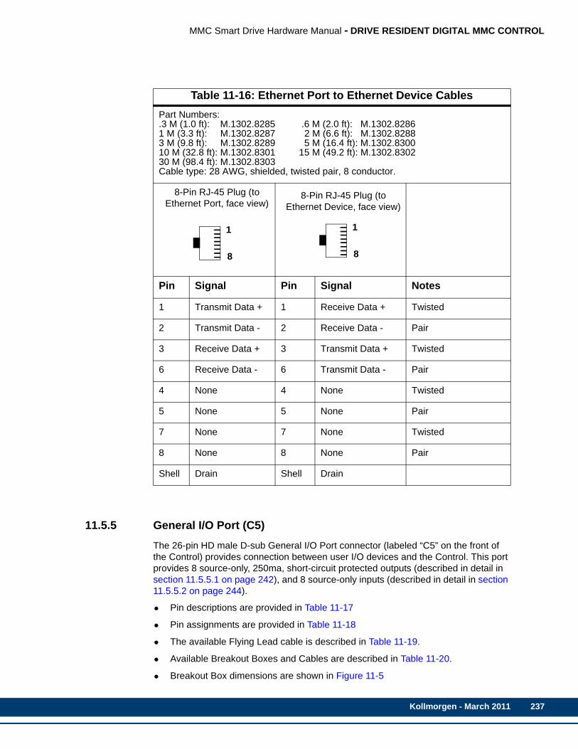
MMC Smart Drive Hardware Manual - DRIVE RESIDENT DIGITAL MMC CONTROL
11.5.5 General I/O Port (C5)The 26-pin HD male D-sub General I/O Port connector (labeled “C5” on the front of the Control) provides connection between user I/O devices and the Control. This port provides 8 source-only, 250ma, short-circuit protected outputs (described in detail in section 11.5.5.1 on page 242), and 8 source-only inputs (described in detail in section 11.5.5.2 on page 244).
• Pin descriptions are provided in Table 11-17
• Pin assignments are provided in Table 11-18
• The available Flying Lead cable is described in Table 11-19.
• Available Breakout Boxes and Cables are described in Table 11-20.
• Breakout Box dimensions are shown in Figure 11-5
Table 11-16: Ethernet Port to Ethernet Device CablesPart Numbers:.3 M (1.0 ft): M.1302.8285 .6 M (2.0 ft): M.1302.82861 M (3.3 ft): M.1302.8287 2 M (6.6 ft): M.1302.82883 M (9.8 ft): M.1302.8289 5 M (16.4 ft): M.1302.830010 M (32.8 ft): M.1302.8301 15 M (49.2 ft): M.1302.830230 M (98.4 ft): M.1302.8303Cable type: 28 AWG, shielded, twisted pair, 8 conductor.
8-Pin RJ-45 Plug (to Ethernet Port, face view)
8-Pin RJ-45 Plug (to Ethernet Device, face view)
Pin Signal Pin Signal Notes
1 Transmit Data + 1 Receive Data + Twisted
2 Transmit Data - 2 Receive Data - Pair
3 Receive Data + 3 Transmit Data + Twisted
6 Receive Data - 6 Transmit Data - Pair
4 None 4 None Twisted
5 None 5 None Pair
7 None 7 None Twisted
8 None 8 None Pair
Shell Drain Shell Drain
1
8
1
8
Kollmorgen - March 2011 237
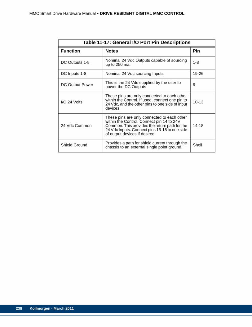
238
MMC Smart Drive Hardware Manual - DRIVE RESIDENT DIGITAL MMC CONTROL
Table 11-17: General I/O Port Pin DescriptionsFunction Notes Pin
DC Outputs 1-8 Nominal 24 Vdc Outputs capable of sourcing up to 250 ma. 1-8
DC Inputs 1-8 Nominal 24 Vdc sourcing Inputs 19-26
DC Output Power This is the 24 Vdc supplied by the user to power the DC Outputs 9
I/O 24 VoltsThese pins are only connected to each other within the Control. If used, connect one pin to 24 Vdc, and the other pins to one side of input devices.
10-13
24 Vdc Common
These pins are only connected to each other within the Control. Connect pin 14 to 24V Common. This provides the return path for the 24 Vdc Inputs. Connect pins 15-18 to one side of output devices if desired.
14-18
Shield Ground Provides a path for shield current through the chassis to an external single point ground. Shell
Kollmorgen - March 2011

MMC Smart Drive Hardware Manual - DRIVE RESIDENT DIGITAL MMC CONTROL
Table 11-18: General I/O Port Pin AssignmentsPin Signal In/Out Connector Pinout
1 DCOUT1 Out
26-pin HD male D-sub
2 DCOUT2 Out
3 DCOUT3 Out
4 DCOUT4 Out
5 DCOUT5 Out
6 DCOUT6 Out
7 DCOUT7 Out
8 DCOUT8 Out
9 24VDCIN In
10-13 IO24V In/Out
14-18 IO24C In/Out
19 DCIN1 IN
20 DCIN2 IN
21 DCIN3 IN
22 DCIN4 IN
23 DCIN5 IN
24 DCIN6 IN
25 DCIN7 IN
26 DCIN8 IN
Shell Drain In
1
26
19
9
Kollmorgen - March 2011 239
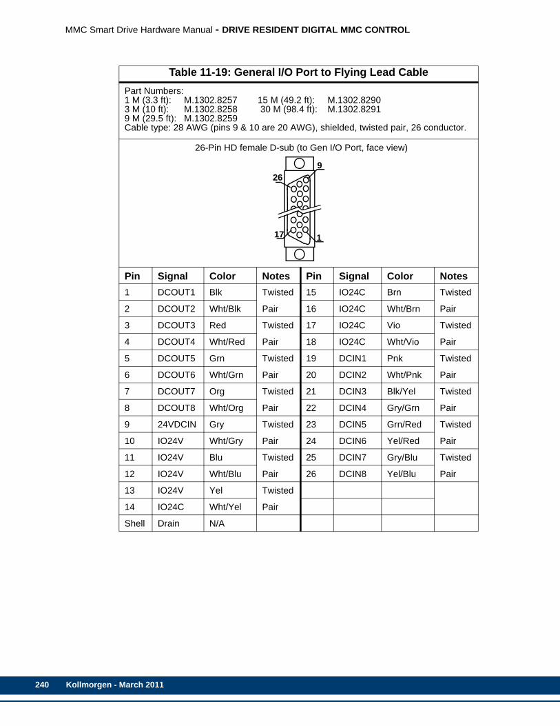
240
MMC Smart Drive Hardware Manual - DRIVE RESIDENT DIGITAL MMC CONTROL
Table 11-19: General I/O Port to Flying Lead CablePart Numbers:1 M (3.3 ft): M.1302.8257 15 M (49.2 ft): M.1302.82903 M (10 ft): M.1302.8258 30 M (98.4 ft): M.1302.82919 M (29.5 ft): M.1302.8259Cable type: 28 AWG (pins 9 & 10 are 20 AWG), shielded, twisted pair, 26 conductor.
26-Pin HD female D-sub (to Gen I/O Port, face view)
Pin Signal Color Notes Pin Signal Color Notes1 DCOUT1 Blk Twisted 15 IO24C Brn Twisted
2 DCOUT2 Wht/Blk Pair 16 IO24C Wht/Brn Pair
3 DCOUT3 Red Twisted 17 IO24C Vio Twisted
4 DCOUT4 Wht/Red Pair 18 IO24C Wht/Vio Pair
5 DCOUT5 Grn Twisted 19 DCIN1 Pnk Twisted
6 DCOUT6 Wht/Grn Pair 20 DCIN2 Wht/Pnk Pair
7 DCOUT7 Org Twisted 21 DCIN3 Blk/Yel Twisted
8 DCOUT8 Wht/Org Pair 22 DCIN4 Gry/Grn Pair
9 24VDCIN Gry Twisted 23 DCIN5 Grn/Red Twisted
10 IO24V Wht/Gry Pair 24 DCIN6 Yel/Red Pair
11 IO24V Blu Twisted 25 DCIN7 Gry/Blu Twisted
12 IO24V Wht/Blu Pair 26 DCIN8 Yel/Blu Pair
13 IO24V Yel Twisted
14 IO24C Wht/Yel Pair
Shell Drain N/A
9
1
26
17
Kollmorgen - March 2011
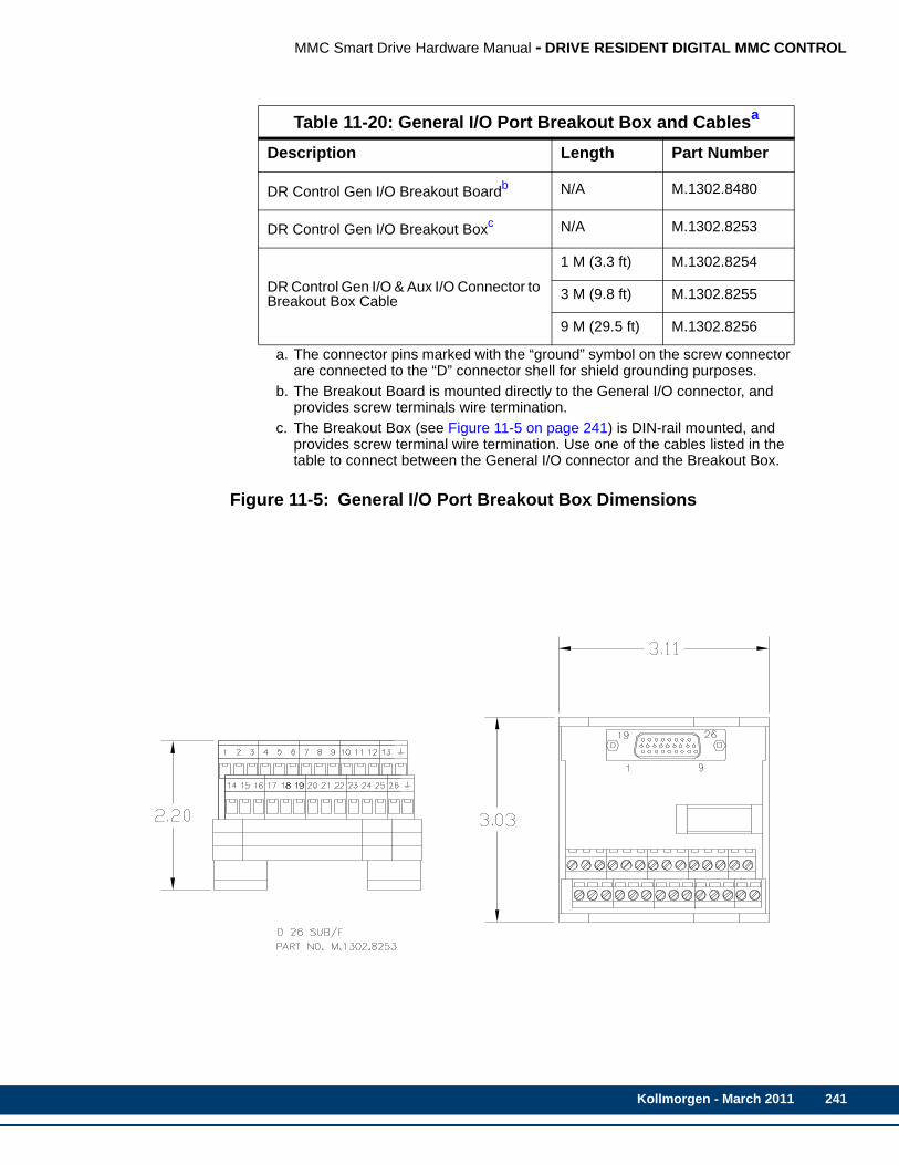
MMC Smart Drive Hardware Manual - DRIVE RESIDENT DIGITAL MMC CONTROL
Figure 11-5: General I/O Port Breakout Box Dimensions
Table 11-20: General I/O Port Breakout Box and Cablesa
Description Length Part Number
DR Control Gen I/O Breakout Boardb N/A M.1302.8480
DR Control Gen I/O Breakout Boxc N/A M.1302.8253
DR Control Gen I/O & Aux I/O Connector to Breakout Box Cable
1 M (3.3 ft) M.1302.8254
3 M (9.8 ft) M.1302.8255
9 M (29.5 ft) M.1302.8256
a. The connector pins marked with the “ground” symbol on the screw connector are connected to the “D” connector shell for shield grounding purposes.
b. The Breakout Board is mounted directly to the General I/O connector, and provides screw terminals wire termination.
c. The Breakout Box (see Figure 11-5 on page 241) is DIN-rail mounted, and provides screw terminal wire termination. Use one of the cables listed in the table to connect between the General I/O connector and the Breakout Box.
Kollmorgen - March 2011 241
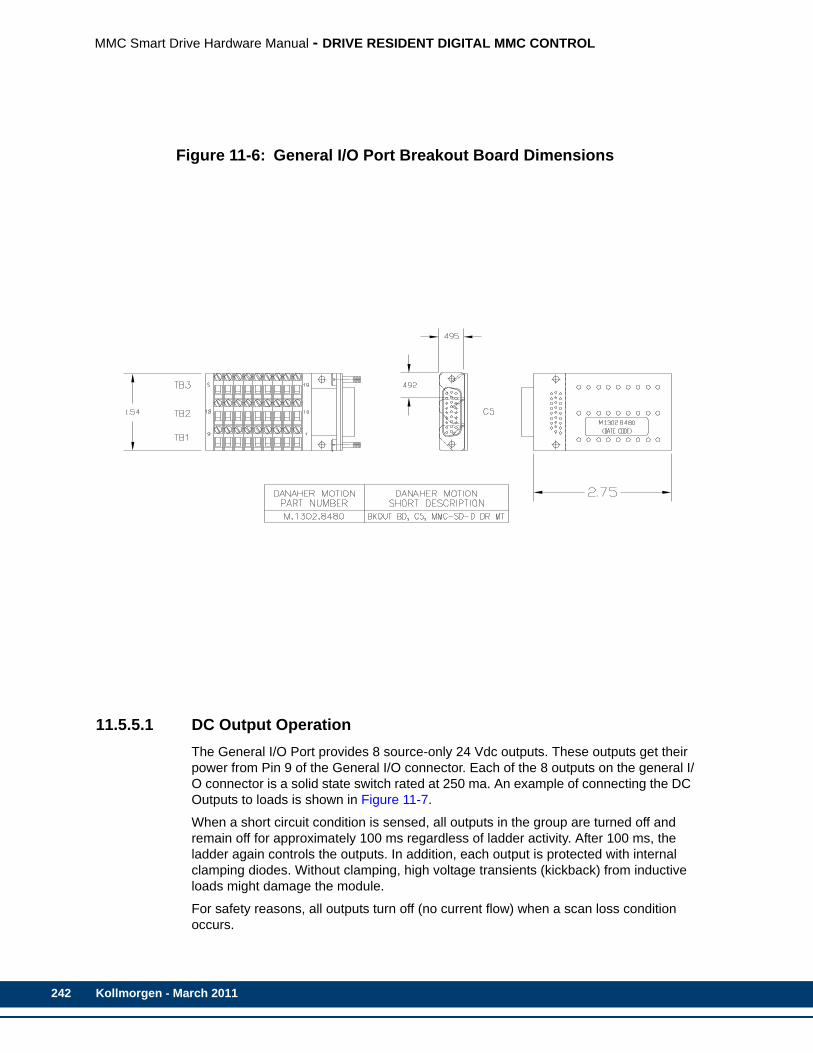
242
MMC Smart Drive Hardware Manual - DRIVE RESIDENT DIGITAL MMC CONTROL
Figure 11-6: General I/O Port Breakout Board Dimensions
11.5.5.1 DC Output OperationThe General I/O Port provides 8 source-only 24 Vdc outputs. These outputs get their power from Pin 9 of the General I/O connector. Each of the 8 outputs on the general I/O connector is a solid state switch rated at 250 ma. An example of connecting the DC Outputs to loads is shown in Figure 11-7.
When a short circuit condition is sensed, all outputs in the group are turned off and remain off for approximately 100 ms regardless of ladder activity. After 100 ms, the ladder again controls the outputs. In addition, each output is protected with internal clamping diodes. Without clamping, high voltage transients (kickback) from inductive loads might damage the module.
For safety reasons, all outputs turn off (no current flow) when a scan loss condition occurs.
Kollmorgen - March 2011

MMC Smart Drive Hardware Manual - DRIVE RESIDENT DIGITAL MMC CONTROL
Figure 11-7: Connecting Output Devices to the General I/O Port (C5)
To
Drive Resident Digital
GENERALCONNECTOR DCOUTPUT PINS
DC Power Supply+ _
SPGCommon
DCOUT5
LOAD
5
7
9
6
8
3
17
4
18
2
151
14
16
MMC Control
DCOUT1
DCOUT2
DCOUT3
DCOUT4
DCOUT6
DCOUT7
DCOUT8
24VDCIN
IO24C
Kollmorgen - March 2011 243

244
MMC Smart Drive Hardware Manual - DRIVE RESIDENT DIGITAL MMC CONTROL
11.5.5.2 DC Input OperationThe General I/O Port provides eight 24 Vdc sourcing inputs.
An example of connecting the DC Inputs to the Control is shown in Figure 11-8.
Kollmorgen - March 2011
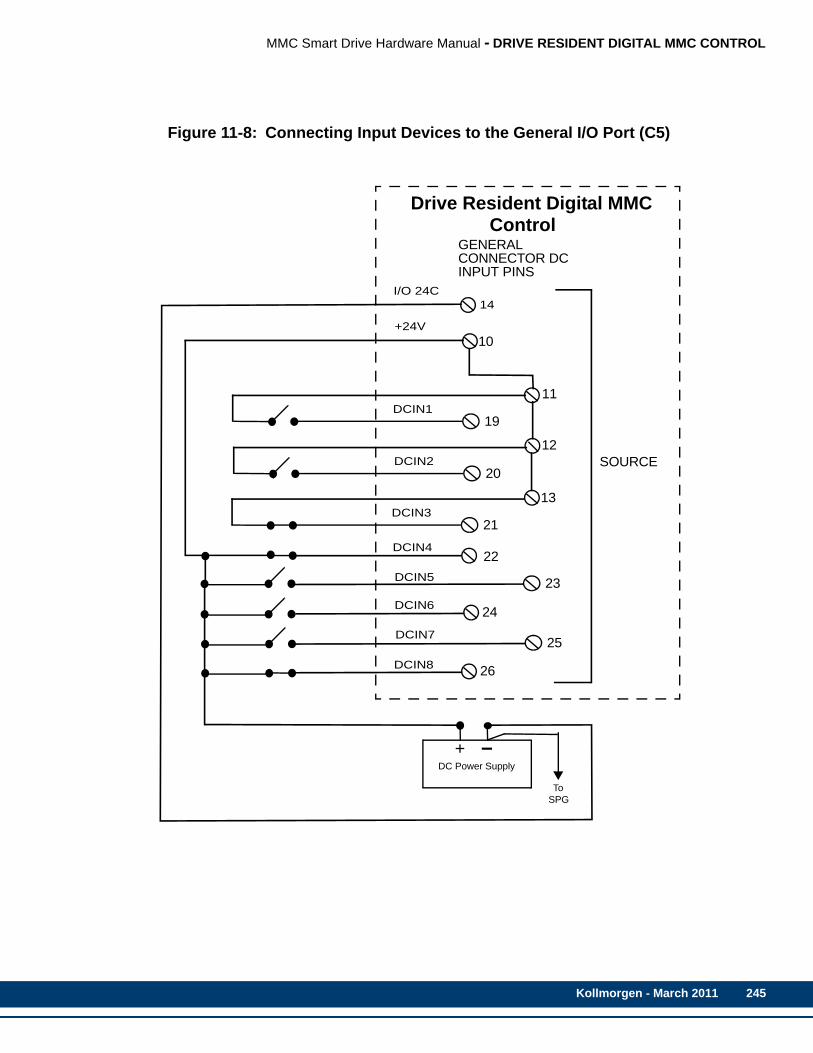
MMC Smart Drive Hardware Manual - DRIVE RESIDENT DIGITAL MMC CONTROL
Figure 11-8: Connecting Input Devices to the General I/O Port (C5)
Drive Resident Digital MMC
GENERALCONNECTOR DCINPUT PINS
11DCIN1
12
13
22
I/O 24C
SOURCE
To
DC Power Supply+ _
SPG
14
19
10
DCIN220
DCIN321
23
24
25
26
+24V
DCIN4
DCIN5
DCIN6
DCIN7
DCIN8
Control
Kollmorgen - March 2011 245
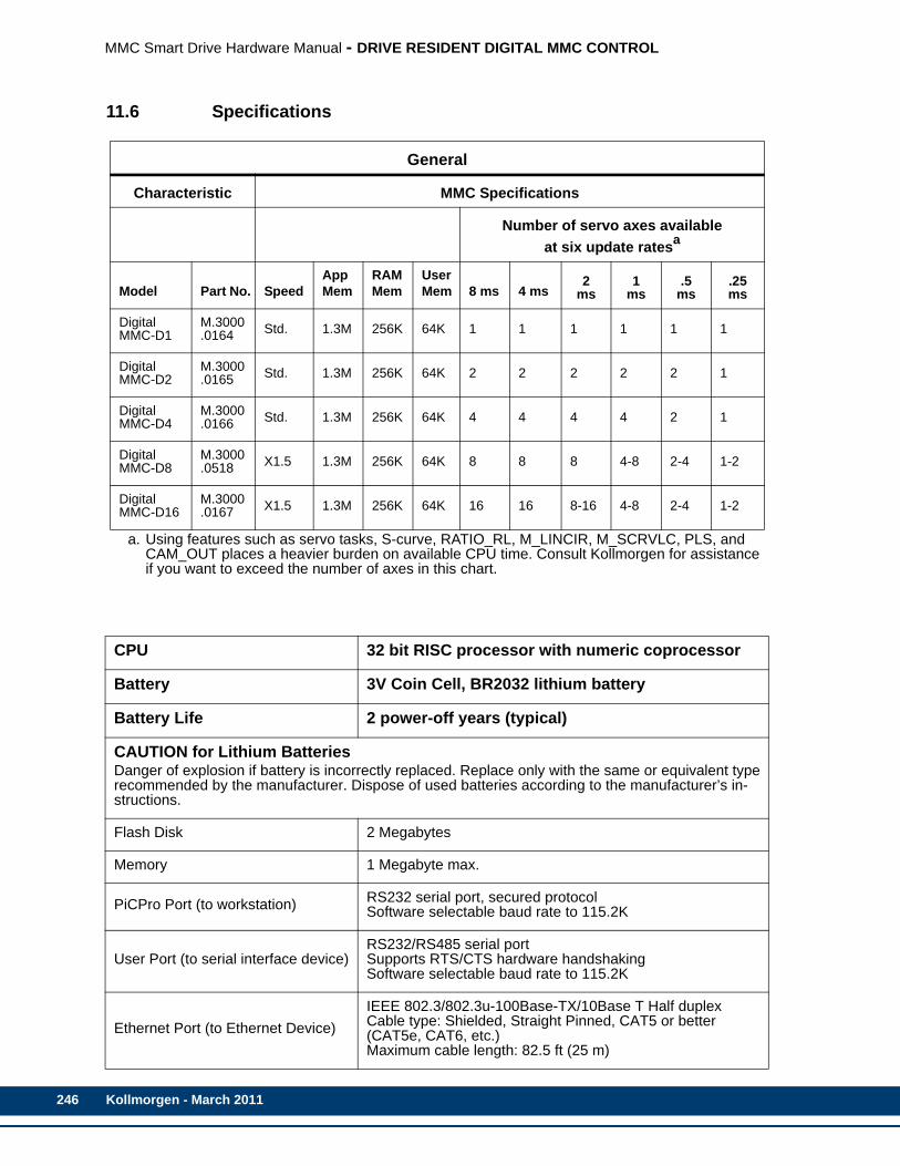
246
MMC Smart Drive Hardware Manual - DRIVE RESIDENT DIGITAL MMC CONTROL
11.6 Specifications
General
Characteristic MMC Specifications
Number of servo axes availableat six update ratesa
a. Using features such as servo tasks, S-curve, RATIO_RL, M_LINCIR, M_SCRVLC, PLS, and CAM_OUT places a heavier burden on available CPU time. Consult Kollmorgen for assistance if you want to exceed the number of axes in this chart.
Model Part No. SpeedApp Mem
RAM Mem
User Mem 8 ms 4 ms
2ms
1ms
.5 ms
.25 ms
Digital MMC-D1
M.3000.0164 Std. 1.3M 256K 64K 1 1 1 1 1 1
Digital MMC-D2
M.3000.0165 Std. 1.3M 256K 64K 2 2 2 2 2 1
Digital MMC-D4
M.3000.0166 Std. 1.3M 256K 64K 4 4 4 4 2 1
Digital MMC-D8
M.3000.0518 X1.5 1.3M 256K 64K 8 8 8 4-8 2-4 1-2
Digital MMC-D16
M.3000.0167 X1.5 1.3M 256K 64K 16 16 8-16 4-8 2-4 1-2
CPU 32 bit RISC processor with numeric coprocessor
Battery 3V Coin Cell, BR2032 lithium battery
Battery Life 2 power-off years (typical)
CAUTION for Lithium BatteriesDanger of explosion if battery is incorrectly replaced. Replace only with the same or equivalent type recommended by the manufacturer. Dispose of used batteries according to the manufacturer’s in-structions.
Flash Disk 2 Megabytes
Memory 1 Megabyte max.
PiCPro Port (to workstation) RS232 serial port, secured protocolSoftware selectable baud rate to 115.2K
User Port (to serial interface device)RS232/RS485 serial portSupports RTS/CTS hardware handshakingSoftware selectable baud rate to 115.2K
Ethernet Port (to Ethernet Device)IEEE 802.3/802.3u-100Base-TX/10Base T Half duplexCable type: Shielded, Straight Pinned, CAT5 or better (CAT5e, CAT6, etc.)Maximum cable length: 82.5 ft (25 m)
Kollmorgen - March 2011

MMC Smart Drive Hardware Manual - DRIVE RESIDENT DIGITAL MMC CONTROL
Input voltage from MMC-SD Drive 20 VDC to 30 VDC
Input power from MMC-SD Drive 250 mA
Time-of-day clock
Clock tolerance
Access via PiCPro 10.2 and above or your application pro-gramAt 25°C (77°F),±1 second per dayOver temperature, voltage and aging variation,+2/-12 seconds per day
General DC Inputs
Configuration Sourcing only. Operates with IEC Type 1 inputs (per IEC 1131-2)
Input voltage Nominal 24 VDC, maximum 30 VDC
Guaranteed on voltage 15 VDC
Guaranteed off voltage 5 VDC
Turn on/off time 1 ms
General DC Outputs
Number of outputs 8 outputs
Input voltage Nominal 24 VDC, 30 VDC maximum
Configuration Eight solid-state switches.
Protection of logic circuits Optical isolation between the logic and field side, transient suppression on the 24V external supply
Maximum current .25 A per output
Voltage range 24 VDC nominal, 5 to 30 VDC
Switch characteristics Solid-state switches
Time delay on for resistive loads 50 µsec max
Time delay off for resistive loads 50 µsec max
Leakage current in off state 0.5 mA max
Switch voltage, maximum ON 1 VDC max
Short circuit protection for each group
15 A (max) pulses for about 130 µsec every 100 msec until short is removed
Scan loss response Outputs turn off
Kollmorgen - March 2011 247

248
MMC Smart Drive Hardware Manual - DRIVE RESIDENT DIGITAL MMC CONTROL
Kollmorgen - March 2011

MMC Smart Drive Hardware Manual - DECLARATIONS OF CONFORMITY
12 Declarations of Conformity
Kollmorgen - March 2011 249
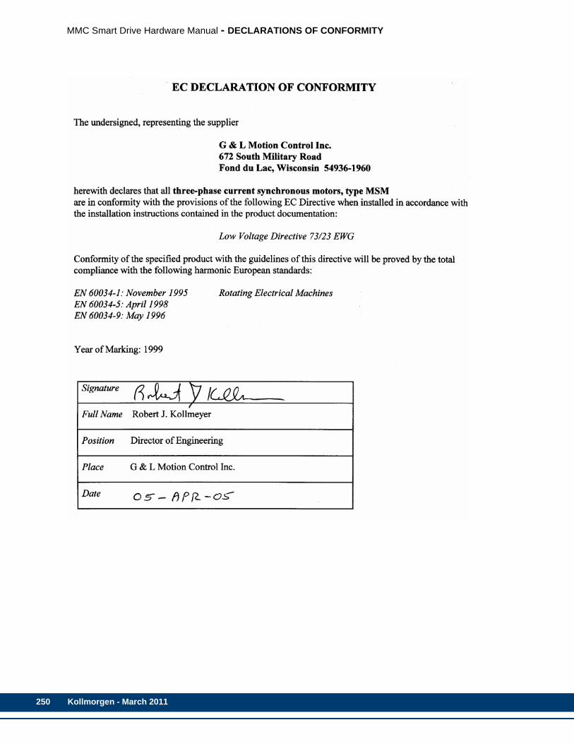
250
MMC Smart Drive Hardware Manual - DECLARATIONS OF CONFORMITY
Kollmorgen - March 2011
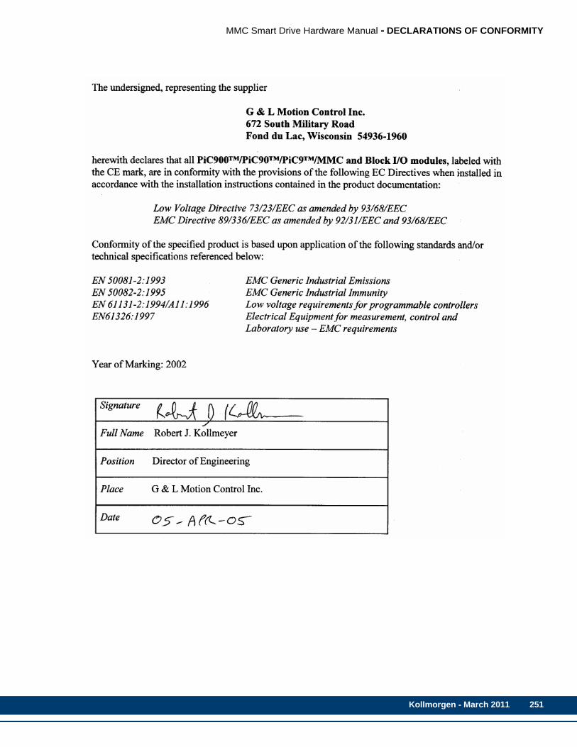
MMC Smart Drive Hardware Manual - DECLARATIONS OF CONFORMITY
Kollmorgen - March 2011 251

252
MMC Smart Drive Hardware Manual - DECLARATIONS OF CONFORMITY
Kollmorgen - March 2011

MMC Smart Drive Hardware Manual - DECLARATIONS OF CONFORMITY
Kollmorgen - March 2011 253

254
MMC Smart Drive Hardware Manual - DECLARATIONS OF CONFORMITY
Kollmorgen - March 2011
MMC Smart Drive Hardware Manual - 460V MMC SMART DRIVE DC BUS SHARING
Appendix A - 460V MMC Smart Drive DC Bus SharingA.1 Introduction
This section discusses DC bus sharing among 2 or more 460V Smart Drives.
DC bus sharing accomplishes 4 things:
• It pools the capacitance of all of the drives.
• It lowers electricity cost.
• It allows multiple dries to share one shunt resistor.
• It allows the shunt energy to be shared among multiple shunt resistors.
Pooling the capacitance increases the Joule energy absorption capability to the sum of the drives connected (Table A-2 on page 260). This lowers energy cost slightly because energy that can be absorbed is not wasted in the shunt resistors. In some applications, this can eliminate the need for a shunt resistor altogether.
Many applications will have one drive motoring while the other is regenerating. This energy is transferred from one drive to the other through the DC bus rather than being dissipated in a shunt. This saves energy cost.
If it is desired to share one shunt resistor instead of using one per drive, the energy flows through the DC bus to the drive controlling the shunt resistor. Its internal circuitry will turn the shunt on when the bus voltage reaches an upper limit.
If it is desired to distribute the shunt load among multiple drives, each having a smaller resistor, then it is important to interconnect the “Shunt On” signals for all drives sharing the DC bus. This ensures that all of the shunt resistors will properly share the load. If this connection is not made, it is likely that only one shunt resistor will dissipate all of the shunt power, overheating it.
A.2 DC Bus Sharing with AC Power to All DrivesWhen sharing DC power among several drives with AC power supplying all of the drives (Figure A-1), all drives must be the same size (for example, all drives must be MMC-SD-4.0-460). When two drives are connected to a shared DC bus in this manner, the combined energy absorption of all drives is available.
3% line reactors are required for all sizes using this configuration to ensure rectifier balance. However, shunt resistors are optional (see below). Refer to Chapter 4 in this manual for information related to fusing, line reactors and shunts. Refer to Chapter 6 for connector information.
When more than one shunt is used with the MMC Smart Drives, it is important to tie the “Shunt On” circuits together so that all shunts get turned on at the same time. For example, in Figure A-1, if the shunt connected to Drive 1 turns on, the “Shunt On” signal will turn on the shunt for Drive 2. The second shunt resistor is optional as long as the “Shunt On” signal is connected as shown. The “Shunt On” signal acts as both an input and an output for each Drive.
Kollmorgen - March 2011 255
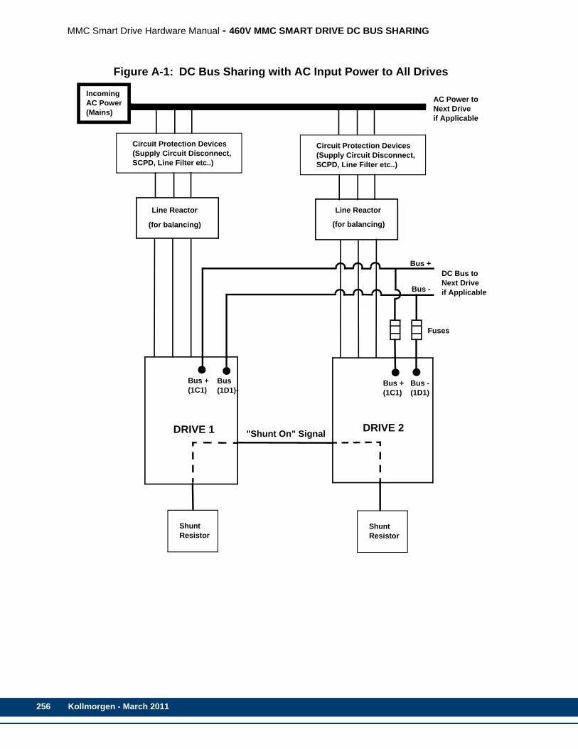
256
MMC Smart Drive Hardware Manual - 460V MMC SMART DRIVE DC BUS SHARING
Figure A-1: DC Bus Sharing with AC Input Power to All Drives
ShuntResistor
DC Bus toNext Driveif Applicable
Bus +
Bus -
Bus + Bus -
DRIVE 1
Bus Bus +
DRIVE 2
Fuses
AC Power toNext Driveif Applicable
Circuit Protection Devices(Supply Circuit Disconnect,SCPD, Line Filter etc..)
Circuit Protection Devices(Supply Circuit Disconnect,SCPD, Line Filter etc..)
ShuntResistor
IncomingAC Power(Mains)
Line Reactor
(for balancing)
Line Reactor
(for balancing)
"Shunt On" Signal
(1C1) (1D1)- (1C1) (1D1)
Kollmorgen - March 2011
MMC Smart Drive Hardware Manual - 460V MMC SMART DRIVE DC BUS SHARING
A.3 DC Bus Sharing with AC Power to One DriveWhen sharing DC power among several drives with AC power supplying just one of the drives (Figure A-2), all drives need not be the same size (for example, one drive may be a MMC-SD-8.0-460, and another drive may be a MMC-SD-1.3-
460). When two or more drives are connected to a shared DC bus in this manner, there are two limits that must be considered:
• The drives not powered by AC must not consume more power than the “Bus power available for linking to other drives” as listed in Table A-1.
• The total power consumed by all drives cannot exceed the greater of “Bus power available for linking to other drives” and the kW rating of the AC powered drive as listed in Table A-1.
For example, assume that the AC powered drive is a MMC-SD-24.0-460 and consumes 14kW, and supplies DC power to two more drives that consume 4kW each (8kW total). From Table A-1, the total DC power available to the non-AC powered drives is 10kW, meeting the first criteria. The total power consumed is 22kW, and since the AC powered drive is a 24kW drive, meets the second criteria.
The continuous current available from the drive would be reduced by the same percentage as the kW. In the example given, the available kW was reduced from 24 to 16kW. Therefore 16/24 = 67%. The drive’s continuous current is reduced by 1/3 from 45 Amps to 30 Amps.
If peak current is to be used at the same time on more than one drive, the total peak current used by all drives must not exceed that of the main drive. If both the main and auxiliary drives will accelerate at the same time, the peak current used by auxiliary drives is subtracted from the available peak current of the main drive. Connection of a shunt to the main drive is optional depending on the results found in sizing the system. The system will have the combined DC Bus capacitance of all drives connected.
Table A-2 on page 260 shows the MMC Smart Drive bus capacitance and energy absorption capability.
:
Kollmorgen - March 2011 257

258
MMC Smart Drive Hardware Manual - 460V MMC SMART DRIVE DC BUS SHARING
Table A-1: kW Ratings for Powered Drive
Drive Model
Bus power available for linking to other drives
Continuous Current (Amps)
Peak Current (Amps)
MMC-SD-1.3-460 2.0kW 3 6
MMC-SD-2.4-460 2.0kW 5.5 11
MMC-SD-4.0-460 5.0kW 9 18
MMC-SD-6.0-460 5.0kW 13.5 27
MMC-SD-8.0-460 5.0kW 18 36
MMC-SD-12.0-460 10.0kW 27.5 55
MMC-SD-16.0-460 10.0kW 36.5 73
MMC-SD-24.0-460 10.0kW 55 110
MMC-SD-30.0-460 10.0kW 69.3 110
MMC-SD-42.0-460 36.0kW 93.3 147
MMC-SD-51.0-460 45.0kW 117.4 184
MMC-SD-65.0-460 58.0kW 152.7 209
Kollmorgen - March 2011

MMC Smart Drive Hardware Manual - 460V MMC SMART DRIVE DC BUS SHARING
Figure A-2: Two or more drives with AC input power to one drive
DC Bus toNext Driveif Applicable
Bus +
Bus -
Bus + Bus -
DRIVE 1
Bus -Bus +
DRIVE 2
Fuses*
Circuit Protection Devices(Supply Circuit Disconnect,SCPD, Line Filter etc..)
ShuntResistor
(Main) (Auxiliary)
IncomingAC Power(Mains)
Line Reactor
*Fuses should be sized to the Auxiliary Drive’s DC bus rating, and must be able to interrupt 700V DC.
(size 3 only)
Mains OnMains On
Shunt OnShunt On
Kollmorgen - March 2011 259
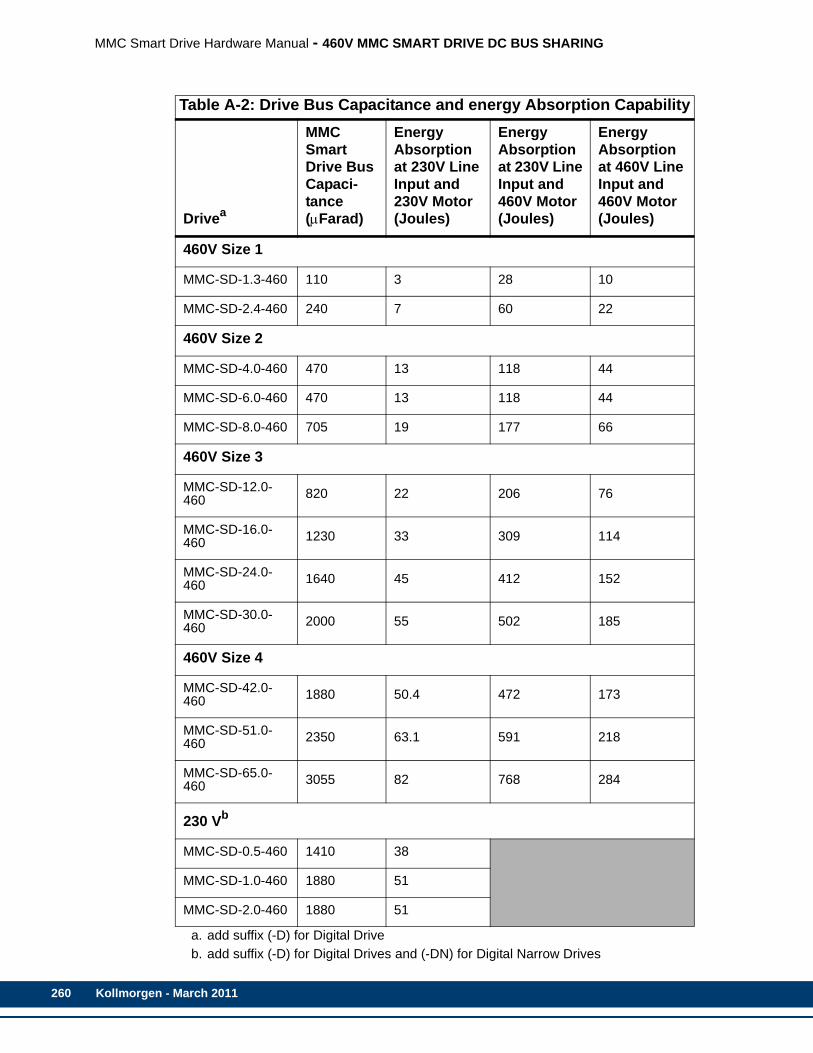
260
MMC Smart Drive Hardware Manual - 460V MMC SMART DRIVE DC BUS SHARING
Table A-2: Drive Bus Capacitance and energy Absorption Capability
Drivea
MMC Smart Drive Bus Capaci-tance (μFarad)
Energy Absorption at 230V Line Input and 230V Motor (Joules)
Energy Absorption at 230V Line Input and 460V Motor (Joules)
Energy Absorption at 460V Line Input and 460V Motor (Joules)
460V Size 1
MMC-SD-1.3-460 110 3 28 10
MMC-SD-2.4-460 240 7 60 22
460V Size 2
MMC-SD-4.0-460 470 13 118 44
MMC-SD-6.0-460 470 13 118 44
MMC-SD-8.0-460 705 19 177 66
460V Size 3
MMC-SD-12.0-460 820 22 206 76
MMC-SD-16.0-460 1230 33 309 114
MMC-SD-24.0-460 1640 45 412 152
MMC-SD-30.0-460 2000 55 502 185
460V Size 4
MMC-SD-42.0-460 1880 50.4 472 173
MMC-SD-51.0-460 2350 63.1 591 218
MMC-SD-65.0-460 3055 82 768 284
230 Vb
MMC-SD-0.5-460 1410 38
MMC-SD-1.0-460 1880 51
MMC-SD-2.0-460 1880 51
a. add suffix (-D) for Digital Driveb. add suffix (-D) for Digital Drives and (-DN) for Digital Narrow Drives
Kollmorgen - March 2011

MMC Smart Drive Hardware Manual - INDEX
IndexNumerics230V Smart Drive 67
24VDC IN/Brake connector 106address switches 74, 75dimensions 116drive I/O connector 98F1/F2 feedback connectors 77LEDs 69motor connector 108PiCPro port (analog drive) 71PiCPro port (digital drive) 69power connector 108regen connector 111specifications 112
24V power connector460V Smart Drive
size 1 127size 2 132size 3 137size 4 142
24VDC IN/Brake connector230V Smart Drive 106
460V Smart Drive24V power connector
size 1 127size 2 132size 3 137size 4 142
AC power connectorsize 1 126size 2 130size 3 135size 4 140
address switches 74, 75connectors
size 1 123size 2 128size 3 133size 4 138
dimensions 159drive connection layout 145drive I/O connector 98F1/F2 feedback connectors 77fan connector
size 4 144motor brake connector
size 1 128size 2 133size 3 138size 4 143
motor connector
size 1 126size 2 131size 3 136size 4 141
PiCPro port (analog drive) 71PiCPro port (digital drive) 69shunt/DC bus connector
size 1 125specifications 146
AAC power connector
460V Smart Drivesize 1 126size 2 130size 3 135size 4 140
address switches230V Smart Drive 74, 75460V Smart Drive 74, 75S200-DLS Drive 169
AKM/DDR motorsF1/F2 encoder cable 90F1/F2 Endat/BiSS cable 86F1/F2 resolver cable 88power cables 192
applicationwiring 25
Auxiliary Feedback PortS200-DLS Drive 173
Bbending radius
cable 189block I/O port
Drive Resident MMC Control 225bonding
mounting 20
Ccable
bending radius 189F1/F2 encoder to AKM/DDR motor 90F1/F2 encoder to FSM motor 94F1/F2 encoder to LSM/MSM motor 92F1/F2 encoder to YSM motor 96F1/F2 Endat/BiSS to AKM/DDR motor 86F1/F2 resolver to AKM/DDR motor 88flex cable installation 190tension 190
CEfilter requirements 24
combination fuse
Kollmorgen - March 2011 261
MMC Smart Drive Hardware Manual - INDEX
262
part numbers 41conformity
european directives 18UL and cUL standards 18
connectingDrive Resident MMC Control 221
connectionsDrive Resident MMC Control 225
connector kitsLSM/MSM motors 193
connectors460V Smart Drive
size 1 123size 2 128size 3 133size 4 138
contents of the manual 7control cabinet
requirements 21
DDC input operation
Drive Resident MMC Control 244DC output operation
Drive Resident MMC Control 242diagnostic
error codes 201, 208Diagnostic Indicator
S200-DLS Drive 169diagnostics
Drive Resident MMC Control 222power on 200runtime 201
Digital LinkLEDs 169
digital link option cardS200-DLS Drive 169
Digital Link PortsS200-DLS Drive 171
dimensions230V Smart Drive 116460V Smart Drive 159cabinet clearance 19motor cable 31
distributionpower 28
drive connection layout460V Smart Drive 145
drive I/O connector230V Smart Drive 98460V Smart Drive 98
Drive I/O Port detailsS200-DLS Drive 180
Drive Resident MMC Control
block I/O port 225connecting 221connections 225DC input operation 244DC output operation 242diagnostics 222error codes 224ethernet port 235front view 218general I/O port 237overview 217PiCPro port 225power LED 222run-time diagnostics 224scan LED 222setup and maintenance 221specifications 246starting an operation 221startup diagnostic LED 223system wiring guidelines 220troubleshooting 222user port 229
Eelectrical service & maintenance safety 14EMI (ElectroMagnetic Interference)
bonding 20error codes
diagnostic 201, 208drive fault 202, 208Drive Resident MMC Control 224
ethernet portDrive Resident MMC Control 235
FF1/F2 feedback connectors
230V Smart Drive 77460V Smart Drive 77
fan cablesLSM/MSM motors 197
fan connector460V Smart Drive
size 4 144faults
diagnostic 201, 208filter, AC power 24flex cable
installation 190installation guidelines 189
front viewDrive Resident MMC Control 218
FSM motorsF1/F2 encoder cable 94
Kollmorgen - March 2011

MMC Smart Drive Hardware Manual - INDEX
Ggeneral I/O port
Drive Resident MMC Control 237grounding
CE single phase 230V drive system 24multiple drives 25protective earth 12system 22
Hhandling the MMC Smart Drive 17heat
controlling 19
II/O Power Port
S200-DLS Drive 180inspection
safety 13installation 18installation guidelines
flex cables 189installing 17
resolver option module 213isolation transformers
230V formula 50460V formula 50
LLEDs
230V Smart Drive 69Digital Link on S200-DLS Drive 169error codes 201, 208S200-DLS drive option card 169
line filtersblock diagram for 3-phase 61CE compliance 60connection diagram for 3-phase 61technical data
230V 63460V 64
LSM/MSM motorsconnector kits 193F1/F2 encoder cable 92fan cables 197power cables 194
Mmaintenance 199manual cleaning procedure 15MMC Control
see Drive Resident MMC Control 217
MMC Smart Driveintroduction 7power 29
motor brake connector460V Smart Drive
size 1 128size 2 133size 3 138size 4 143
motor cables 189motor connector
230V Smart Drive 108460V Smart Drive
size 1 126size 2 131size 3 136size 4 141
mounting 21bonding 20
Nnoise
see bonding 20
Ooperation
safety 14overview
Drive Resident MMC Control 217
Ppart numbers
combination fuse 41PicPro port
Drive Resident MMC Control 225PiCPro port (analog drive)
230V Smart Drive 71460V Smart Drive 71
PiCPro port (digital drive)230V Smart Drive 69460V Smart Drive 69
powerdistribution in MMC 28MMC Smart Drive 29
power cablesAKM/DDR motors 192LSM/MSM motors 194
power connector230V Smart Drive 108
power LEDDrive Resident MMC Control 222
proceduremanual cleaning 15
Kollmorgen - March 2011 263
MMC Smart Drive Hardware Manual - INDEX
264
protective earthgrounding 12
Rregen connector
230V Smart Drive 111Requirements
Transformer 36resolver option module
installing 213theory of operation 213
run-time diagnosticsDrive Resident MMC Control 224
SS200-DLS Drive
address switches 169Auxiliary Feedback Port 173Diagnostic Indicator 169Digital Link Option Card 169Digital Link Ports 171Drive I/O Port details 180I/O Power Port details 180introduction 167LEDs 169specifications 186
safe-off on 230V Drivesoperation on non-Safe-off Drives 108operation on Safe-off Drives 107signal requirements 107
safetyafter shutdown 13cleaning 15electrical service & maintenance 14inspection 13operating safely 14operation 14signs 12system 11warning labels 12
Sales and Service 266scan LED
Drive Resident MMC Control 222Service 266setup and maintenance
Drive Resident MMC Control 221shields 26shunt modules
connecting 52, 58shunt/DC bus connector
460V Smart Drivesize 1 125
shunts 50
choosing 50signs
safety 12single point ground (SPG)
checklist 22software
required 8specifications
230V Smart Drive 112460V Smart Drive 146Drive Resident MMC Control 246optional resolver module 216S200-DLS Drive 186
starting an operationDrive Resident MMC Control 221
startup diagnostic LEDDrive Resident MMC Control 223
storagebefore installation 17
storing the drive 17system mounting requirements
ventilation 18system wiring guidelines
Drive Resident MMC Control 220
Ttechnical support contacts 9tension
cable 190theory of operation
resolver option module 213Transformer
Size 36troubleshooting
drive error codes 202, 208Drive Resident MMC Control 222general 200hardware wiring 200
UUnpacking 17user port
Drive Resident MMC Control 229
Vventilation 18
Wwarning label
danger, warning, caution 13hazard 12
Web Address 266wiring
Kollmorgen - March 2011

MMC Smart Drive Hardware Manual - INDEX
application 25connecting shunt modules 52, 58connections for 3-phase line filter 61EMC compliant 25interface cables 30preparing motor connection wires 31routing high/low voltage cables 30
terminating 230V motor power cable 32terminating 460V power cable 33
YYSM motors
F1/F2 encoder cable 96
Kollmorgen - March 2011 265
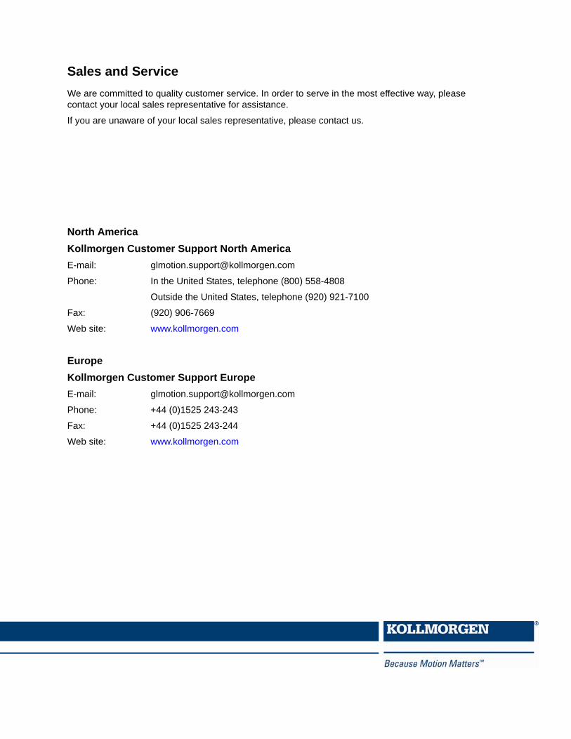
Sales and ServiceWe are committed to quality customer service. In order to serve in the most effective way, please contact your local sales representative for assistance.
If you are unaware of your local sales representative, please contact us.
North AmericaKollmorgen Customer Support North AmericaE-mail: [email protected]
Phone: In the United States, telephone (800) 558-4808
Outside the United States, telephone (920) 921-7100
Fax: (920) 906-7669
Web site: www.kollmorgen.com
EuropeKollmorgen Customer Support EuropeE-mail: [email protected]
Phone: +44 (0)1525 243-243
Fax: +44 (0)1525 243-244
Web site: www.kollmorgen.com

![[ SMART PRoducT MARking ] · smart product marking smart product marking [ SMART SoluTion ] ORIGINAL ORIGINAL 8 9 EingabE / Start ErEigniS übEr: DatEnquEllEn auch kombination von](https://img.pdfslide.us/doc/110x75/605bcd2001586e05a25e7bf0/-smart-product-marking-smart-product-marking-smart-product-marking-smart-solution.jpg)


![(e)MMC/SD/SDIO State of Affairsconnect.linaro.org.s3.amazonaws.com/sfo17... · First MMC stack by Russell King in kernel 2.6.9 [MMC] Add MMC core](https://img.pdfslide.us/doc/110x75/5f5ee69463a1e67f0c5f43dc/emmcsdsdio-state-of-first-mmc-stack-by-russell-king-in-kernel-269-mmc-add.jpg)